Embed Size (px)
DESCRIPTION
Simulation Chlorobenzene Plant by using ASPEN Plus
Citation preview

SIMULATION OF CHLOROBENZENE PLANT IN ASPEN PLUS
Submitted in partial fulfilment of the Requirement for the Degree of Bachelor of Technology In Chemical Engineering By ASHISH MISHRA 1100105008 Under Guidance of MR. SUDEEP
DEPARTMENT OF CHEMICAL ENGINEERING
DEENBANDHU CHHOTU RAM UNIVERSITY OF SCIENCE AND TECHNOLOGY
MURTHAL, SONIPAT-131039
April, 201

2
ACKNOWLEDGEMENT
It gives me immense pleasure to acknowledge many people who knowingly and unwillingly helped me, to complete my project.
I express my gratitude to Dr. D.P. Tiwari, Chairman, Department of Chemical Engineering for his cooperation and encouragement during the completion of this course. I extend my utmost gratitude to Mr.Sudeep , Teaching Associate, Department of Chemical Engineering, my project guide, who has always stood by my side and guided, appreciated and encouraged me to get into more and more ventures. I also thank all the faculty of department for their direct and indirect role in completion of this project. Continuing the same they enlightened me in the various stages during the development of this project and provided me with many insights and useful examples, which proved to be of immense help in successful completion of this project.
ASHISH MISHRA1100005008
3
CERTIFICATE
I hereby certify that the work which is being presented in the B.Tech. Major Project Report entitled “Simulation Of Chlorobenzene Production Plant in ASPEN PLUS”, in partial fulfillment of the requirements for the award of the Bachelor of Technology in Chemical Engineering and submitted to the Department of Chemical Engineering, Deenbandhu Chhoturam University Of Science and Technology, Murthal is an authentic record of my own work carried out under the supervision of Mr. Sudeep, Teaching Associate , Chemical Engineering Department.
The matter presented in this thesis has not been submitted by me for the award of any other degree elsewhere.
Signature of Candidate
ASHISH MISHRA
11001005008
This is to certify that the above statement made by the candidate is correct to the best of my knowledge.
Date: MR. SUDEEP Teaching Associate
Project Guide

4
CONTENT
Page no.
ACKNOWLEDGEMENT
CERTIFICATE
1. ABSTRACT 62. LITERATURE REVIEW 7-9 3. PROBLEM STATEMENT 104. FLOW SHEET 115. PROCESS SIMULATION OF ASPEN PLUS 12-206. RESULTS 21-247. SENSITVITY ANALYSIS 258. CONCLUSIONS 279. REFARENCES 28

5
LIST OF TABLES AND GRAPH
TABLES
1. Table 2.1 Chlorobenzene Properties 2. Table 5.1 Various Streams 3. Table 6.1,P-liq stream4. Table 6.2,P-di stream 5. Table 6.3 mass balance6. Table 7.1 sensitivity analysis
GRAPHS
1. Graph 7.1 sensitivity analysis monochlorobenzene2. Graph 7.2 sensitivity analysis p-dichlorobenzene

6
1. ABSTRACT
Chlorobenzene is an aromatic organic compoundwith the chemical formula C6H5Cl. This colorless, flammable liquid is a common solvent and a widely used intermediate in the manufacture of other chemicals. Chlorobenzene can persist in soil for several months, in air for about 3.5 days, and in water for less than one day. Humans may be exposed to this agent via breathing contaminated air (primarily via occupational exposure), eating contaminated food or water, or by coming into contact with contaminated soil (typically near hazardous waste sites). However, because it has only been found at 97 out of 1,177 NPL hazardous waste sites, it is not considered a widespread environmental contaminant. Chlorobenzene is economically produced by the chlorination of benzene. This project simulate the chlorobenzene plant in aspen plus .After reaction in reactor,first we remove HCL acid by using caustic wash. Now our product stream contains unreacted benzene and chlorobenzene product.We know that boiling point of benzene is 800C and monochlrobenzene is 1310C,so there is large difference in boling points ,we can separate these by using simple distillation DSTWU block in aspen plus. Light component is benzene and monochlorobenzene is component. Finally we separate out p-dichlorobenzene from monochlorobenzene. Difference between the boiling point of the p-dichlorobenzene (174 0 C ) and monochlorobenzene (1310C ) is large ,so we can separate easily by using simple distillation. After the simulation we get desired 95 % pure monochlorobenzene product. Aspen plus gives an idea for NPSH of pump ,number of minimum and actual stages for distillation column,reactor volume etc. At last we use sensitivity analysis tool,in which we vary the flow rate of benzene and get effect of this variation on chlorobenzene production.

7
2. LITRATURE REVIEW
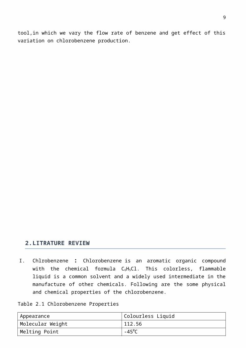
I. Chlrobenzene : Chlorobenzene is an aromatic organic compound with the chemical formula C6H5Cl. This colorless, flammable liquid is a common solvent and a widely used intermediate in the manufacture of other chemicals. Following are the some physical and chemical properties of the chlorobenzene.
Table 2.1 Chlorobenzene Properties
Appearance Colourless LiquidMolecular Weight 112.56Melting Point -450CBoiling Point 1310CFlash Point 270CIgnition Point 5900CSolubility Water solubility :500 mg/L(at 200C)
II. Manufacturing Process of Chlorobenzene
The basic principle behind the manufacture of chlorobenzene is the chlorination of benzene with or without the presence of a catalyst (Friedel-Craft reaction). The products of such a reaction would be chlorobenzene, dichlorobenzene, trichlorobenzene and the higher chlorinated benzenes. In actual practice in the industry, only chlorobenzene and small amounts of dichlorobenzene are formed. The amounts of dichlorobenzene and higher substituted chlorobenzene formed can be reduced greatly by using selective catalysts and modifying reaction conditions. Thus essentially chlorination of benzene can be considered as taking place in three pairs of two stages each:
(1) Chlorination of benzene to monochlorobenzene and dichlorobenzene.
(2) Chlorination of dichlorobenzene to trichlorobenzene and tetrachlorobenzenes.
(3) Chlorination of tetrachlorobenzenes to pentachlorobenzenes and hexachlorobenzene.
Chlorination can be carried out either batch wise or continuously. When minimum formation of dichlorobenzenes is required then the latter procedure is followed. In the batch process, benzene is contained in a deep, iron or steel vessel, fitted with lead cooling coils. The chlorine feed-pipe enters at the bottom of the chlorinator and the catalyst is ferric chloride. The temperature is maintained at less than 45°C. HCl produced in the reaction can be recovered after separation from benzene by washing with a refrigerated solvent. A temperatures below 40°C, the rate of formation of dichlorobenzene is very low and this fact is used to suppress formation of dichlorobenzene in the continuous process. A typical continuous process plant consists of a series of small, externally cooled steel vessels containing the catalyst. Chlorine is supplied to each vessel through suitably placed inlets and the temperature of the reaction is maintained between 20 - 40°C.As the chlorobenzene is formed, it leaves the chlorination zone at a speed that allows no further chlorination to take place. Unreacted benzene and chlorobenzene are continuously separated by fractional distillation, returning the benzene to the chlorination stage and the efficiency of this process can be as high as 95%.
8
There are different ways in which the chlorination of benzene can be brought about and these form the different processes for the manufacture of chlorobenzene
A. Raschig Process: In this process, benzene is chlorinated by chlorine that has been produced in situ in the reactor by the catalytic oxidation of hydrogen chloride. A pre-heated mixture of benzene vapour, air, steam, and HCl, at ordinary pressure, is brought into contact at 220°- 260°C with a catalyst of copper oxide. 2% of the total benzene combusts, giving rise to about on quarter of the total heat output of the process. The disadvantage of this process is that the high temperature greatly favours high combustion rates of benzene and the reaction may become uncontrollable. Moreover the high costs of this vapour phase chlorination process in comparison with other available processes, allows it to be highly uneconomical for chlorobenzene manufacture and thus renders it obsolete.
B. Loeser and Schmidt: In this process mixture of benzene vapour, HCl, and air is reacted at 150 – 300°C in contact with a copper hydroxide-alumina catalyst (in the form of a fluidised mass), may be regarded as a variant of Raschig’s Process.
C. Quartz Tube Process: chlorination of benzene is carried out in a quartz tube at 400 - 500°C. Here the principal product obtained is chlorobenzene along with minor amounts of dichlorobenzene.
The disadvantages of all these processes are low efficiency and high temperature, which may make the reaction uncontrollable leading to formation of higher chlorobenzene. Based on all the above considerations, the continuous liquid phase chlorination of benzene at a temperature of about 40°C is best suited for production of large amounts of monochlorobenzene in the industry. The process is economically viable too making it the most popular process being used in the industry for the manufacture of monochlorobenzene all over the world.As already known, industrial chlorination of benzene is carried out in the liquid phase at moderate temperature with the help of a catalyst to produce monochlorobenzene and minor amounts of dichlorobenzene. Chlorobenzene and the o- and p-dichlorobenzene are the principal products. The reaction is a consecutive, competitive reaction. Liquid benzene is fed to a chlorinator operating at 2.4 bars. The feed enters at 25°C, at atmospheric pressure and also contains some water. Gaseous chlorine is fed to this tank, also at atmospheric pressure and at 25°C and is considered fully pure. There may be several chlorinators operating in series or parallel depending upon the degree of chlorination of benzene required. Ferric chloride is usually the catalyst. This can be added as a solution in benzene, or as iron turnings, or scrap that provides the ferric chloride in the chlorinator. Since the reaction is exothermic cooling is required to maintain the temperature at about 40C. The HCl gas (90% of the HCl formed) leaving the reactor is first cooled to condense the impurities (benzene and chlorinated products) and then it is scrubbed in a scrubber using refrigerated chlorobenzene. The crude chlorobenzene stream leaving the reactor is washed with NaOH solution (20 wt%; maintained slightly alkaline to protect downstream equipment from corrosion) in a pre-neutralizer. The product stream is free of HCL.The product is fed to a benzene recovery column, which is a distillation column. Here the bottoms are almost 100 % pure chlorobenzene. The tops contain 98 % by weight of benzene and 2% chlorobenzene and all of the benzene is recycled to the benzene storage via a purifier. From the purifier the monochlorobenzene is sent to the refrigeration system. The bottoms from the benzene column contain monochlorobenzene and dichlorobenzene. This is fed to the chlorobenzene column, which is again a distillation column. This may contain 12 to 20 trays and is operated at a pressure ranging from 3–7 lb/in.2 abs. The temperature in the chlorobenzene column may be between 100 - 120°C.Monochlorobenzene is the overhead
9
distillate product of a purity of 99% and dichlorobenzene is the bottom residue product of a purity of 97%.The reactions involved in the process are as follows: C6H6 + Cl2 C6H5Cl + HCl C6H5Cl + Cl2 C6H5Cl2 + HCl
Dichlorobenzene is assumed to be a para-isomer. Formation of trichloro isomers is neglected. When concentrations of dissolved chlorine remains essentially constant then reactions are first order.rb = -k1xbrm = k1xb – k2xm rd = k2xm where k1 = 1 x 10⁻⁴ s-1 at 55°C , k2 = 0.15 x 10⁻⁴ s-1 at 55°C, b = benzene, m = monochlorobenzene, d = dichlorobenzene
III. Reaction Mechanism : Chlorination of benzene is an example of electrophilic substitution. These electrophilic substitution reactions involving the generation of a powerful electrophile (electron pair acceptor) which subsequently attacks the electron rich Π (pi) electron system of the double bond. Arenes tend to undergo substitution, rather than addition, because substitutions allows the very stable benzene ring to remain intact.Chlorine is bubbled into a mixture of the arene and anhydrous aluminium chloride catalyst. Other catalysts like anhydrous iron(III) chloride can be used, and they are collectively known as halogen carriers.
Electrophilic substitution by halogen in benzene ring
The non-polar and uncharged chlorine molecule is not a strong enough an electrophile to disrupt the pi electron system of the benzene ring. The aluminium chloride reacts with a chlorine molecule to form a positive chlorine ion Cl+ which is a much stronger electron pair accepting electrophile and a tetrachloroaluminate(III) ion (either this or an AlCl3-Cl2 complex - details not needed for A level).
An electron pair from the delocalised pi electrons of the benzene ring forms a C-Cl bond with the electron pair accepting positive chlorine ion forming a highly unstable carbocation. It is very unstable because the stable electron arrangement of the benzene ring is partially broken to give a 'saturated' C (top right of ring).
The tetrachloroaluminate(III) ion, formed in step (1), abstracts a proton from the highly unstable intermediate carbocation to give the chloro-aromatic product, hydrogen chloride gas and reform the aluminium chloride catalyst.

10
IV. Uses of ChlorobenzenesChlorobenzene is mainly used as raw material for the synthesis of chemicals including triphenylphosphine (catalyst for organic synthesis), phenylsilane, and thiophenol (pesticide and pharmaceutical intermediate). It is also used as raw material for the synthesis of solvent for organic synthesis reactions including methylenediphenyldiisocyanate, urethane raw material, agriculturaladjuvants, paint and ink, and cleaning solvent for electronics. Chlorobenzene was previously used as raw material for the synthesis of o- and p-nitrochlorobenzene and 2,4-dinitrochlorobenzene.
s
1. Problem Statement
Model a Chlorobenzene production plant in Aspen Plus software utilizing the following design specification and given parameters.
Design Specifications:
1. Produce more than 95 mol percent pure monochlorobenzene2. Produce more than 80 mol percent pure p-dichlorobenzene
Given Parameters:
Reactions:
C6H6 + Cl2 C6H5Cl + HCl
C6H5Cl + Cl2 C6H5Cl2 + HCl
Feed:
a) Benzene: Flow rate = 200 kmol/hr Purity = 95 mol %
b) Chlorine gas: Flow rate = 500 kmol/hr Purity = 100 mol %Conditions: ambient temperature, atmospheric pressure
Caustic:
Flow rate = 25 kmol/hr

11
Composition = 10 mol% NaOH (balance Water)
Conditions: ambient temperature, atmospheric pressure
4 .FLOW SHEET
Flow Sheet of Chlorobenzene Plant

12
5.Process Simulation in Aspen Plus
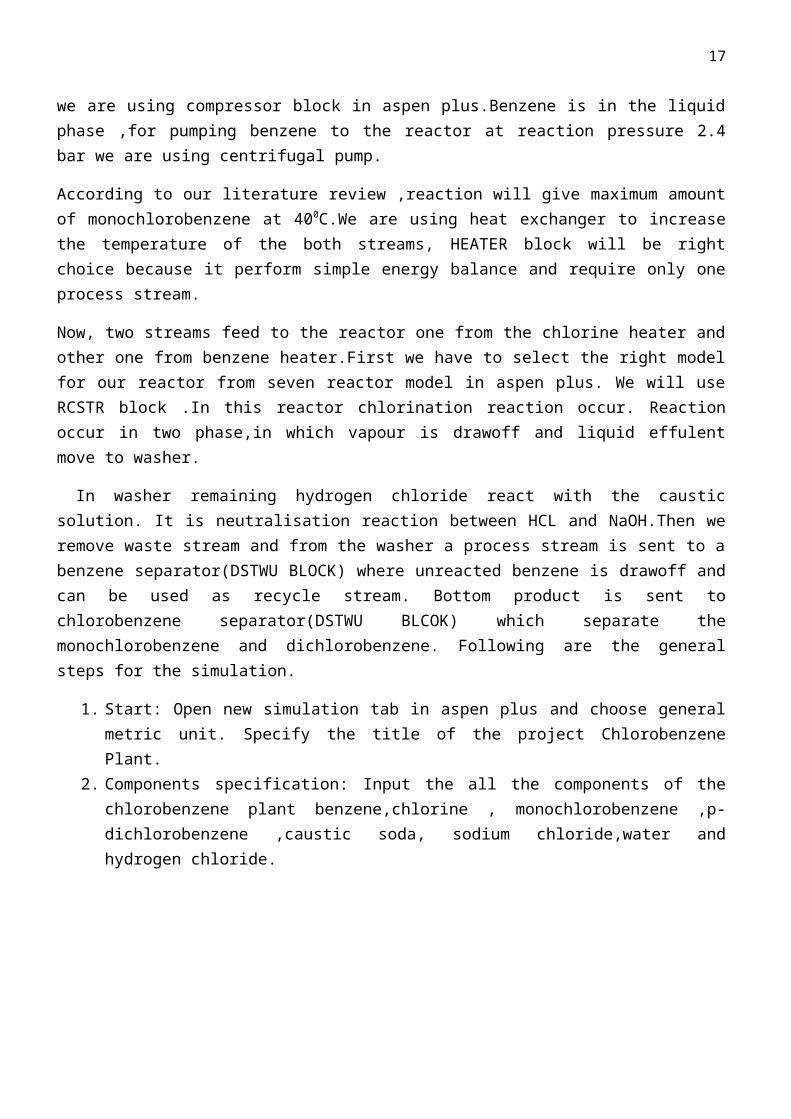
We have two reactant benzene and chlorine. Chlorine is in the vapour phase ,we have to compress it upto 2.4 bar pressure ,for this purpose we are using compressor block in aspen plus.Benzene is in the liquid phase ,for pumping benzene to the reactor at reaction pressure 2.4 bar we are using centrifugal pump.
According to our literature review ,reaction will give maximum amount of monochlorobenzene at 400C.We are using heat exchanger to increase the temperature of the both streams, HEATER block will be right choice because it perform simple energy balance and require only one process stream.
Now, two streams feed to the reactor one from the chlorine heater and other one from benzene heater.First we have to select the right model for our reactor from seven reactor model in aspen plus. We will use RCSTR block .In this reactor chlorination reaction occur. Reaction occur in two phase,in which vapour is drawoff and liquid effulent move to washer.
In washer remaining hydrogen chloride react with the caustic solution. It is neutralisation reaction between HCL and NaOH.Then we remove waste stream and from the washer a process stream is sent to a benzene separator(DSTWU BLOCK) where unreacted benzene is drawoff and can be used as recycle stream. Bottom product is sent to chlorobenzene separator(DSTWU BLCOK) which separate the monochlorobenzene and dichlorobenzene. Following are the general steps for the simulation.
1. Start: Open new simulation tab in aspen plus and choose general metric unit. Specify the title of the project Chlorobenzene Plant.
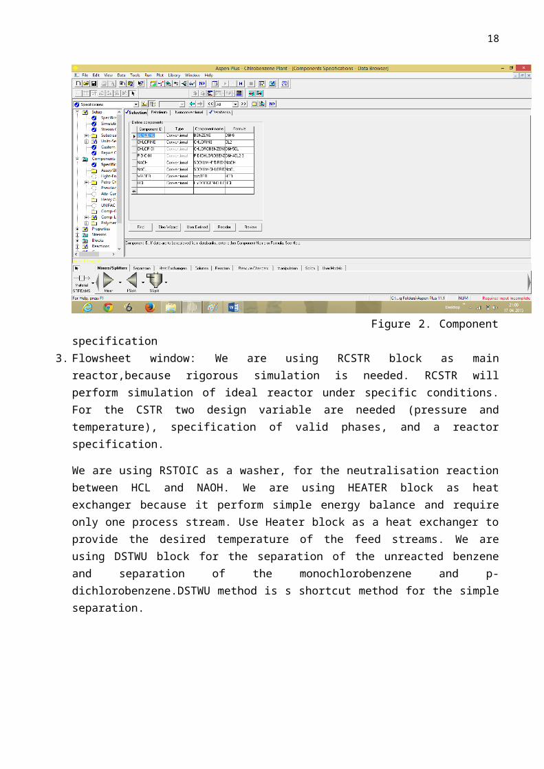
2. Components specification: Input the all the components of the chlorobenzene plant benzene,chlorine , monochlorobenzene ,p-dichlorobenzene ,caustic soda, sodium chloride,water and hydrogen chloride.
Figure 2. Component specification3. Flowsheet window: We are using RCSTR block as main reactor,because rigorous simulation is
needed. RCSTR will perform simulation of ideal reactor under specific conditions. For the

13
CSTR two design variable are needed (pressure and temperature), specification of valid phases, and a reactor specification.
We are using RSTOIC as a washer, for the neutralisation reaction between HCL and NAOH. We are using HEATER block as heat exchanger because it perform simple energy balance and require only one process stream. Use Heater block as a heat exchanger to provide the desired temperature of the feed streams. We are using DSTWU block for the separation of the unreacted benzene and separation of the monochlorobenzene and p-dichlorobenzene.DSTWU method is s shortcut method for the simple separation.
Figures 3 flow-sheet windowTable 5.1 Various Streams
Stream Name Attached BlockCL-Feed Inlet for chlorine compressorBZ-Feed Inlet for benzene pumpCL-Feed1 Inlet for chlorine heat exchangerBZ-Feed1 Inlet for benzene heat exchangerCL –Feed2 Inlet for RCSTR reactorBZ-Feed2 Inlet for RCSTR reactorP-VAP Outlet from RCSTR ,vapour draw OffP-LIQ Outlet from RCSTR (contain liquid product )CAUSTIC Inlet for Washer (contain caustic wash)WASTE Outlet from Washer(contain water)CRUDE Inlet for benzene separator(contains unreacted
benzene and chlorobenzene product P-BZ Outlet from benzene separator(contain
unreacted benzene )BTMS Outlet from benzene separator(contain
chlorobenzene product)P-MONO Outlet from chlorobenzene separator(contain
monochlorobenzene)P-DI Outlet from chlorobenzene separator(contain
p-dichlorobenzene)

14
4. Blocks In Aspen Plus 1) Reactor: Reactions are usually the heart of the chemical processes in which relatively
cheap raw materials are converted to more economically favorable products. In other cases, reactions play essential safety and environmental protection roles. In any case, proper design and operation of the reactor is required to provide the desired outcome. Such design is usually based on thermodynamics, chemical kinetics, and transport studies coupled with experience and economic considerations. When studying chemical reactions we need to determine what are the reactants and products needed, to what extent will the reaction proceed, and how fast it will proceed. The study of such factors in addition to the detailed design of the reactor consist the chemical reaction engineering field in which process simulation can be of great help. There are seven blocks for reaction modeling in Aspen that can perform calculations based on the stoichiometry, yield, equilibrium, and Gibbs minimization, plus the kinetic models for CSTR and PFR. In addition, a batch model is available for batch reactors.
RStoic: When the reaction stoichiometry is known but information on kinetics isnot available (or not important). The block must have one or more feed streams, one required output stream. Optional connections are the water decant and input and output heat streams.We are using RStoic block as washer .In washer neutralisation reaction between HCL and Caustic will occur
RYield: The second block in the Reactors library, RYield, performs the calculations based on the yield. This block does not require exact information about the stoichiometry or kinetics. Similar input to that of RStoic is needed here for the exit stream. The yield is defined as mole or mass of each component per total mass input to the block. Inert components can be defined in the same form and will not be included in the yield. No heat of reaction can be calculated here because the stoichiometry of the reaction is not known.
REquil: When one or more reactions involved are equilibrium reaction, the REquil block can be used. The block requires knowledge of the reaction stoichiometry, and performs chemical and phase equilibrium reactions. Unlike the previous blocks, the REquil block has a vapour and liquid phase product streams (both are required). The only required information for this block is the output stream and the reaction.
RCSTR: When rigorous simulation of reactors is needed, the RCSTR is used. This block perform simulation of ideal reactors operated under specific conditions. For the CSTR two design variables are needed (pressure and temperature or heat duty), specification of the valid phases, and a reactor specification. For the plug reactor, a specification is needed for the type of the reactor (specific temperature, adiabatic, or cooled). Depending on the type choice, the required specification will vary temperature or temperature profile, no specifications are needed or heat transfer coefficient.
5. Stream input: Provide the specification of the feed streams (Benzene feed, Chlorine feed, Caustic material) according to the problem statement. Our benzene feed stream contain 95% pure benzene at 293 K and 1 atm with the flow rate of 200 kmol/hr Our chlorine feed contains 100%

15
pure chlorine at 293 k temperature and 1 atm with flow rate of 500 kmol/hr. Caustic feed for the washer contain 10% aq. NaOH with the flow rate of 25 kmol/hr.
Figures 4 benzene Feed
Figures 5 Caustic Feed Stream Input Window

16
Figure 6 Chlorine Feed Stream Window
6. Block Input: Specify the discharge pressure of 2.4 bar in pump and compressor block. Then specify the input for the heater block with 328 K and 2.4 bar pressure. Now specify the input for distillation block(DSTWU),first for the benzene separator(DIST1) use reflux ratio 1.5 and select benzene as heavy component and chlorobenzene as light component. Then input the data for the chlorobenzene separator(DIST1),here monochlorobenzene is light component and p-dicholorobenzene as heavy component.
17
Figures 8 Chlorine Compressor Window
Figures 9 Benzene Pump window
18
Benzene Heat Exchanger
Chlorine Heat Exchanger

19
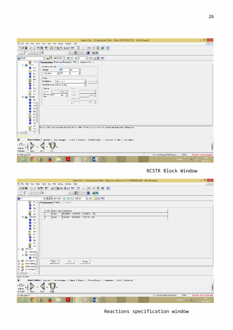
RCSTR Block Window
Reactions specification window

20
Washer Block
Benzene separator

21
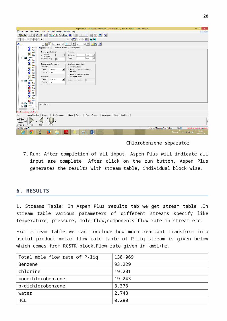
Chlorobenzene separator
7. Run: After completion of all input, Aspen Plus will indicate all input are complete. After click on the run button, Aspen Plus generates the results with stream table, individual block wise.
6. RESULTS
1. Streams Table: In Aspen Plus results tab we get stream table .In stream table various parameters of different streams specify like temperature, pressure, mole flow,components flow rate in stream etc.
From stream table we can conclude how much reactant transform into useful product molar flow rate table of P-liq stream is given below which comes from RCSTR block.Flow rate given in kmol/hr.
Total mole flow rate of P-liq 138.069Benzene 93.229chlorine 19.201monochlorobenzene 19.243p-dichlorobenzene 3.373water 2.743HCL 0.280
Table 6.1 P-liq stream
Similarly we can check purity of monchlorobenzene in P-mono stream.
Total flow rate of P-mono stream (kmol/hr) 19.449Benzene 0.932Chlorine traceMonochlorobenzene 18.481p-dichlorobenzene 0.034

22
water 0.002
Purity of monochlorobenzene = (18.481/19.449)*100 = 94.77% Purity
Similarly we can check purity of p-dichlorobenzene in P-Di stream
Total mole flow rate P-Di stream (kmol/hr) 6.217p-dichlorobenzene 3.340NaOH 2.220NACL 0.280Benzene TraceChlorine Trace
Table 6.2 P-di stream
2.Block results:
A. PUMP
B. Chlorine Compressor

23
C. Benzene Heater
D. Chlorine Heater
E. Reactor(RCSTR)

24
F. Washer
G. Benzene Separator(DIST1)
3.Overall Mass Balance
Components In(kmol/hr) Out(kmol/hr)Benzene 190 164.828Chlorine 500 471.365Mononchlorobenzene 0 21.7081p-dichlorobenzene 0 3.46342NaOH 2.50 2.21NaCl 0 0.280305Water 32.50 32.78033

25
HCL 0 28.3546 Table 6.3 Overall Mass balanceTOTAL BALANCEMoles(kmol/hr) in = 725.00Moles (kmol/hr) out = 725.00
7.SENSITIVITY ANALYSIS
Aspen plus provide us sensitivity tool under model analysis tab.In sensitivity analysis we will vary flow rate of benzene from 200 kmol/hr to 300 kmol/hr and effect of this variation on production of monochlorobenzene and p-dichlorobenzene.
Benzene flow rate (kmol/hr) Monochlorobenzene(mol frac) p-dichlorobenezene(mol frac)200 0.9506 0.5573220 0.9512 0.5916240 0.9517 0.6196260 0.9520 0.6430280 0.9523 0.6627300 0.9525 0.6797
26
Graph 7.1 Sensitivity analysis
From this plot we can conclude molefraction of monchlorobenzene will increase in P-mono stream by increase the moler flow rate of benzene from 200 to 300kmol/hr.
Graph 7.2 Sensitivity analysis
Similarly we can see ,by increasing flow rate of benzene from 200 to 300 kmol/hr ,mole fraction of p-dichlorobenzene will increase in P-Di stream.

27
8.CONCLUSION
From this project work, it can be concluded that the simulation of chlorobenzene successfully done and parameters and conditions obtained are practically feasible.For the design of production plant we got various specification of process equipment like pump, reactor ,distillation column. Under the specified condition we got 95% pure monochlorobenzene.
28
REFERENCES
1. "NIOSH Pocket Guide to Chemical Hazards #0121".National Institute for Occupational Safety and Health (NIOSH).
2. U. Beck, E. Löser "Chlorinated Benzenes and other Nucleus-Chlorinated Aromatic Hydrocarbons" Ullmann's Encyclopedia of Industrial Chemistry, 2012, Wiley-VCH, Weinheim.doi:10.1002/14356007.o06_o03
3. Rossberg, Manfred; Lendle, Wilhelm; Pfleiderer, Gerhard; Tögel, Adolf; Dreher, Eberhard-Ludwig; Langer, Ernst; Rassaerts, Heinz; Kleinschmidt, Peter; Strack, Heinz; Cook, Richard; Beck, Uwe; Lipper, Karl-August; Torkelson, Theodore R.; Löser, Eckhard; Beutel, Klaus K.; Mann, Trevor (2006). "Ullmann's Encyclopedia of Industrial Chemistry - Chlorinated Hydrocarbons".doi:10.1002/14356007.a06_233.pub2. ISBN 3527306730.
4. Booth, Gerald (2000). "Ullmann's Encyclopedia of Industrial Chemistry - Nitro Compounds, Aromatic".doi:10.1002/14356007.a17_411. ISBN 3527306730.
5. Weber, Manfred; Weber, Markus; Kleine-Boymann, Michael (2004). "Ullmann's Encyclopedia of Industrial Chemistry - Phenol".doi:10.1002/14356007.a19_299.pub2. ISBN 3527306730.
6. Rehfuss, M.; Urban, J. (2005). "Rhodococcus phenolicus sp. nov., a novel bioprocessor isolated actinomycete with the ability to degrade chlorobenzene, dichlorobenzene and phenol as sole carbon sources". Systematic and Applied Microbiology 28 (8): 695–701. doi:10.1016/j.syapm.2005.05.011. PMID 16261859. editErratum: Rehfuss, M. (2006). "Erratum to "Rhodococcus phenolicussp. nov., a novel bioprocessor isolated actinomycete with the ability to degrade chlorobenzene, dichlorobenzene and phenol as sole carbon sources" [Systematic and Applied Microbiology 28 (2005) 695–701]". Systematic and Applied Microbiology 29 (2): 182–110.doi:10.1016/j.syapm.2005.11.005
7. CDC - NIOSH Pocket Guide to Chemical Hazards8. McCabe, W., Smith, J. and Harriott, P. (2004). Unit Operations of Chemical Engineering (7th
ed.). McGraw Hill. ISBN 0-07-284823-5.9. Kister, Henry Z. (1992). Distillation Design (1st ed.). McGraw-Hill. ISBN 0-07-034909-6.10. King, C.J. (1980). Separation Processes (2nd ed.). McGraw Hill. ISBN 0-07-034612-7.11. Perry, Robert H. and Green, Don W. (1984). Perry's Chemical Engineers' Handbook (6th ed.).
McGraw-Hill. ISBN 0-07-049479-7.
Felder, R., Roussea, W. (2005). Elementary Principles of Chemical Processes (3rd ed.). Wiley. ISBN 978-0-471-68757-3.
12. Beychok, Milton (May 1951). "Algebraic Solution of McCabe-Thiele Diagram". Chemical Engineering Progress.
13. Seader, J. D., and Henley, Ernest J. (1998). Separation Process Principles. New York: Wiley. ISBN 0-471-58626-9.
14. Process Simulation and Control Using Aspen plus”, Jana AK15. “Distillation Design And Control Using ASEPN Simulation”,William L. Luyben16. “Unit Process” P.H. Groggins17. Study Of Chlorobenzene Plant,Lafayette College