Embed Size (px)
Citation preview
Procedia Technology 11 ( 2013 ) 974 – 979
2212-0173 © 2013 The Authors. Published by Elsevier Ltd.Selection and peer-review under responsibility of the Faculty of Information Science & Technology, Universiti Kebangsaan Malaysia.doi: 10.1016/j.protcy.2013.12.283
The 4th International Conference on Electrical Engineering and Informatics (ICEEI 2013)
Simulation and Testing of a Typical On-Board Charger for ITB Electric Vehicle Prototype Application
Agus Purwadi, Jimmy Dozeno, Nana Heryana*
Electrical Power Engineerng, Institut Teknologi Bandung, Jl. Ganesha 10, Bandung, 40123, West Java, Indonesia
Abstract
Electric Vehicle charging infrastructure is fundamental for EV developmentsince their availability can reduce the EV on-board energy storage (battery). The EV limited range whichis caused due to limited capacity of EV battery can be solved by making EV charging infrastructure available on strategic places.In this paper,itwill be presented the simulation and testing results of a typical on-board used in ITB-1 electric vehicle prototype. Simulation of charger circuits is done by PSIM.It is expected that this study can contribute for further research and development on EV charging system infrastructure.
© 2013 The Authors. Published by Elsevier B.V.Selection and peer-review under responsibility of the Faculty of Information Science and Technology, Universiti Kebangsaan Malaysia.
Keywords: Simulation and Testing; EV Charging infrastucture; Charging Standard; Typical On-board Charger;
1. Introduction
The increasing of people awareness for reducing the carbon emission push public to change the mode of transport into alternative one that utilize more renewable energy. In respond of this trends, otomotive industry start to produce and also make a long term planning on electric car and also hybrid car.
The electric car gives so many advantages not only from the economic standpoint but also from environmental issue which has become a big concern in this climatic change and global warming years. The emergence of electric car is expected by means the growing research and development by manufacturer, and the spreading of charging infrastructure in the cities.
* Corresponding author. Tel+62-22-2503316; fax: +62-22-2508132.E-mail address: [email protected]
Available online at www.sciencedirect.com
© 2013 The Authors. Published by Elsevier Ltd.Selection and peer-review under responsibility of the Faculty of Information Science & Technology, Universiti Kebangsaan Malaysia.
ScienceDirect
975 Agus Purwadi et al. / Procedia Technology 11 ( 2013 ) 974 – 979
The electric car also can help us lessening the dependence of the fossil energy and open a chance for utilizing the renewable energy as the primary energy. This also will make positive impact for the environment since the reducement of the emission that contributed for the global warming.
The growing of the electric car usage in the next ten years will be related with several important factors. Those are the international standard for electric car, the standard for universal charging infrastructure, universal supporting equipments, and also a user-friendly software application. A number of organization that has been established try to provide such standard, some of those are the international energy agency(IEA), the society for automobile engineers(SAE), and the institute of electrical and electronic engineers (IEEE). [1]
Charging infrastructure is really needed because the adequate presence of these infrastructure could reduce the capacity needed in the on-board car energy storage. The short distance range of the car whichis caused by the restricted capacity of the battery could be resolved by building these charging infrastructure in strategic locations. Then, the costs spent for the energy storage will be reduced.
The same perspective in standard for electric car charging system is a very important factor. By applying the standards surely will make the charging infrastructure recognized in public and also will create a good interaction between the user and the technology used. From the economic stance, these also will reduce manufacture costs.
2. Conductive charging system
There are two basic function that must be fulfilled by the charging system of electric car. Those are the two electrical functions and one mechanical functions. The battery of the electric car operate in DC voltage varies and depends on the rated voltage, the state of charge, and and rate of charge and discharge. The first electric function is to rectify the ac voltage into dc voltage. The second is to regulate the voltage supplied into the battery in order to control the rate correspond with the battery characteristic. Both of this electric function are the manifestation of a charger. And the latter function, the mechanic, is to couple physically the electric car with the EVSE.
The conductive charging system consists of the charger and the coupler. There are 2 types of charger, the on-board charger(OBC) and off-board charger. OBC is a charger that installed permanently on the car, whilst the off-board charger is out of the car.
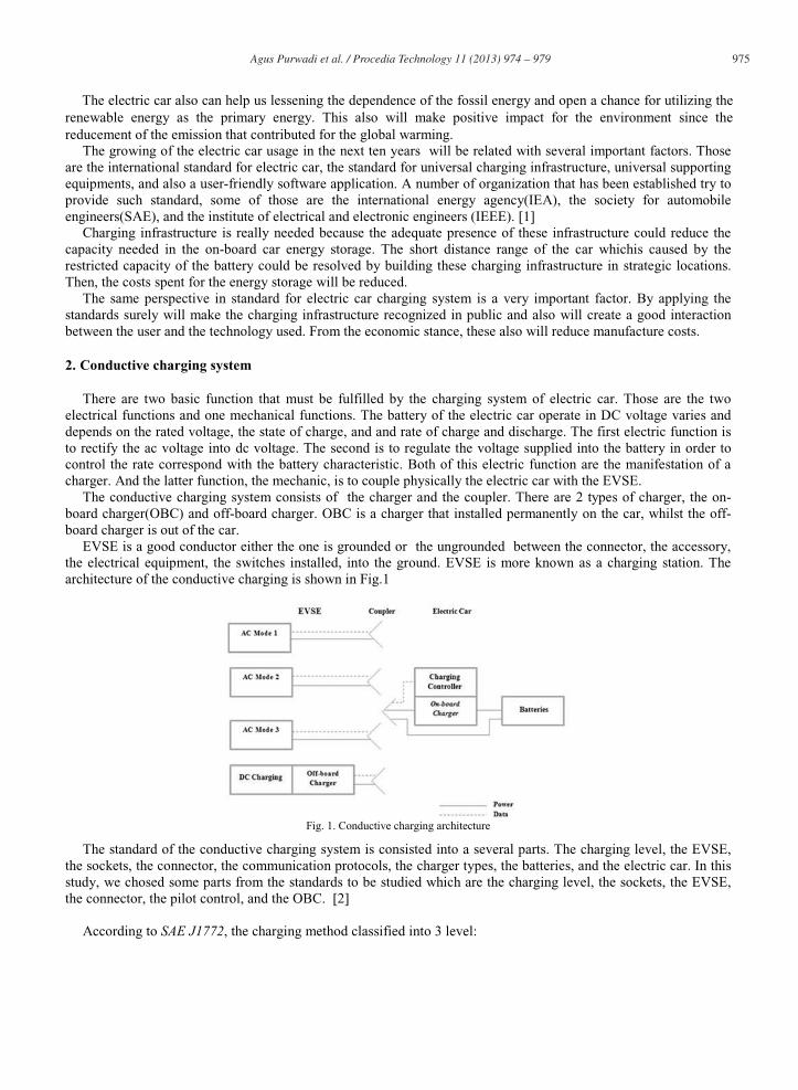
EVSE is a good conductor either the one is grounded or the ungrounded between the connector, the accessory, the electrical equipment, the switches installed, into the ground. EVSE is more known as a charging station. The architecture of the conductive charging is shown in Fig.1
Fig. 1. Conductive charging architecture
The standard of the conductive charging system is consisted into a several parts. The charging level, the EVSE, the sockets, the connector, the communication protocols, the charger types, the batteries, and the electric car. In this study, we chosed some parts from the standards to be studied which are the charging level, the sockets, the EVSE, the connector, the pilot control, and the OBC. [2]
According to SAE J1772, the charging method classified into 3 level:
976 Agus Purwadi et al. / Procedia Technology 11 ( 2013 ) 974 – 979
Level 1: Charging method in which the electric car is supplied through a standard outlet (NEMA 5-15R) with maximum current 12 A and rated voltage at 120 V-Single phase. The OBC has capacity approximately 1.9 kWLevel 2: Charging method in which the electric car is supplied through electric vehicle supply equipment(EVSE) with maximum current up to 32 A in maximum voltage 240 V-single phase.DC charging: Charging method in which the car is supplied by DC source through EVSE and an off-board charger with maximum current up to 400 A in maximum voltage at 600 Volt DC.
The fact that the electric car should be loaded physically by OBC and also the good prospect of the electric car in the future make OBC to meet the standard required, as follow:
The single phase input;High efficiency;Low harmonics;Power factor almost unity.Inexpensive ;Minimum size and weight;Security standard while operates;
PFC is neeed to meet the IEC 1000-3-2standard in regulation of line current harmonics. On base of that, the general diagram of OBC that mostly used is the two level OBC consist of the PFC converter and DC/AC converter. The input filter is also needed to prevent harmonics and noises entering the distribution line. To meet the security standard there should be an isolation between the charger output and the source. General Schematic Diagram for OBC described in fig.2 [3].
Fig. 2. Typical OBC block diagram
3. PFC simulation
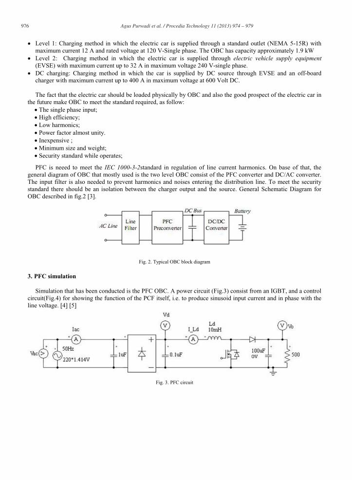
Simulation that has been conducted is the PFC OBC. A power circuit (Fig.3) consist from an IGBT, and a control circuit(Fig.4) for showing the function of the PCF itself, i.e. to produce sinusoid input current and in phase with the line voltage. [4] [5]
Fig. 3. PFC circuit
977 Agus Purwadi et al. / Procedia Technology 11 ( 2013 ) 974 – 979
Fig. 4. Control circuit of PFC
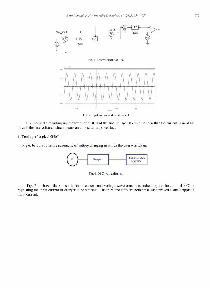
Fig. 5. Input voltage and input current
Fig. 5 shows the resulting input current of OBC and the line voltage. It could be seen that the current is in phase in with the line voltage, which means an almost unity power factor.
4. Testing of typical OBC
Fig 6. below shows the schematic of battery charging in which the data was taken.
Fig. 6. OBC testing diagram
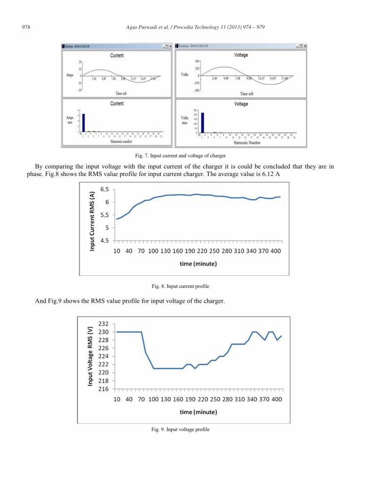
In Fig. 7 is shown the sinusoidal input current and voltage waveform. It is indicating the function of PFC in regulating the input current of charger to be sinusoid. The third and fifth are both small also proved a small ripple in input current.
978 Agus Purwadi et al. / Procedia Technology 11 ( 2013 ) 974 – 979
Fig. 7. Input current and voltage of charger
By comparing the input voltage with the input current of the charger it is could be concluded that they are in phase. Fig.8 shows the RMS value profile for input current charger. The average value is 6.12 A
Fig. 8. Input current profile
And Fig.9 shows the RMS value profile for input voltage of the charger.
Fig. 9. Input voltage profile

979 Agus Purwadi et al. / Procedia Technology 11 ( 2013 ) 974 – 979
Table 1 shows the values of several parameters measured in the test.
Table 1. Measured parameter
Summary Information Voltage Current
Frequency
Power
KW
KVA
KVAR
Peak KW
Total PF
DPF
50.1
1.43
1.44
0.16
2.83
0.99
0.99
RMS
Peak
Crest
THD Rms
THD Fund
220
303
1.38
3.0
3.0
6.55
9.36
1.43
4.4
4.4
5. Conclusion
From this study wan can get several conclusions as follows:
Conductive charging system for electric car in mode 1 consists of the coupler and the on-board charger(OBC) i.e. the charger that placed in the car. PFC configuration in the charger has a big role in increasing the power quality of charger input hence increasing the efficiency. OBC typical testing in the lab proves that OBC is two-level converter with the first level is the PFC configuration with power factor value near 1.
Acknowledments
This research was funded by Directorate General of Higher Education, Ministry of Education and Culture, through Molina ITB program year 2012.
References
[1] Foley A.M, Winning I.J. State of The Art in Electric Vehicle Charging Infrastructure IEEE. 2010.[2] Electric Vehicle Conductive Charge Coupler”. Standard SAE J1772.[3] Koo KW, Kim D.H, Woo D.G. Topology comparison for 6.6l<W On Board Charger:Performance, Efficiency, and Selection
Guideline. IEEE. 2012.[4] Park, Sang-Hoon. “Battery charging system for PHEV and EV using single phase AC/DC PWM buck converter”, University of
Sungkyunkwan. 2010.[5] Mohan, Undeland, Robins. PowerElectronics.I. : Wiley, 2003.