Embed Size (px)
Citation preview
M
3-phase
Inverter
DC/DC
converter
12V Lead-
acid baery
Starter/
Generator
48V Lithium-
ion baery
Electronic
load
M
3-phase
Inverter
Single switch
topology
12V Lead-
acid baery
Starter/
Generat
or
48V
Lithium-
ion
baery
Electronic
load
Simulating & Evaluating feasibility to integrate charging of 12Vbattery with 48V drivetrain for Dual Voltage 48V/12V Mild Hy-brid vehicles
Master’s thesis in Electrical Power Engineering
Tanmay Shukla
Department of Electrical Power Engineering at Electrical EngineeringCHALMERS UNIVERSITY OF TECHNOLOGYGothenburg, Sweden 2017

Master’s thesis 2017
Simulating & Evaluating feasibility to integratecharging of 12V battery with 48V drivetrain forDual Voltage 48V/12V Mild Hybrid vehicles
Tanmay Shukla
Department of Electrical Power EngineeringDivision of Electrical Engineering
Chalmers University of TechnologyGothenburg, Sweden 2017
Simulating & Evaluating feasibility to integrate charging of 12V battery with 48Vdrivetrain for Dual Voltage 48V/12V Mild Hybrid vehiclesTanmay Shukla
© Tanmay Shukla, 2017.
Supervisor:Jonas Forsell, VOLVO Cars CorporationSören Erikson, VOLVO Cars CorporationPeter Almhagen, VOLVO Cars CorporationExaminer: Prof. Yujing Liu, Department of Electrical Power Engineering
Master’s Thesis 2017:Department of Electrical Power EngineeringDivision of Electrical EngineeringChalmers University of TechnologySE-412 96 GothenburgTelephone +46 31 772 1000
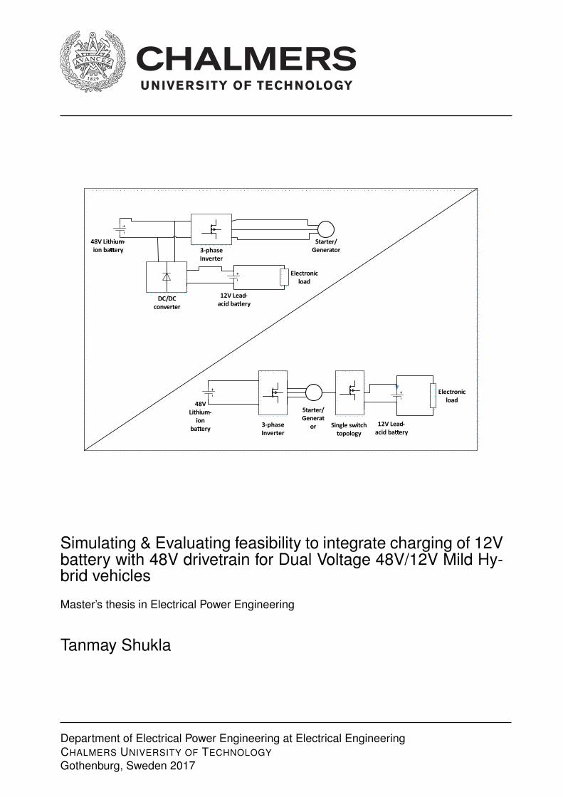
Cover: Electrical schematic showing Mild hybrid Dual voltage system with separateDC/DC converter for charging 12V battery & Integrated charging for 12V battery
Gothenburg, Sweden 2017
iv
Simulating & Evaluating feasibility to integrate charging of 12V battery with 48Vdrivetrain for Dual Voltage 48V/12V Mild Hybrid vehiclesTanmay ShuklaDepartment of Electrical Power EngineeringChalmers University of Technology
AbstractDual voltage energy storage systems have become common in mild hybrid vehiclesdue to their advantages such as increased stability and reliability of the system. Theyserve a viable solution for increasing demand of power for Mild hybrid vehicles. Thedual voltage in mild hybrids contains two level of voltages; 48V battery is usedfor electrical drivetrain and 12V battery is used to power auxiliary system of thevehicles. The demand for power for these auxiliary systems is increasing due toadditional safety systems implemented in the car and hence, it is crucial to haverequired level of SOC for 12V battery. In current system, this is achieved by aseparate dc/dc converter unit to charge the 12V battery pack. But, this unit isquite bulky and costly and hence, it is required to find an alternate solution tocharge the 12V battery without using a separate dc/dc converter.This thesis focuses on investigating on an integrated charger topology suitable tocharge 12V battery for Mild hybrid Dual voltage 48V/12V system. It also checksthe feasibility of the topology to charge the 12V battery continuously under threemodes of motor operation; Motoring mode, Regeneration mode and idle mode. Thework mainly focuses on developing a simulation model which can simulate differentmodes of motor for mild hybrid vehicle for charging the 12V. The motivation behindthe thesis is to integrate the 12V charging with 48V drivetrain which will reduce theoverall size and cost of the drivetrain system. The analysis is done based on chargerefficiency and generation of ripple for the three modes of motor operation.
Keywords: Mild Hybrid vehicles, Dual voltage energy storage systems, IntegratedCharger topology, Common mode voltage
v


AcknowledgementsI would like to thank Chalmers University of Technology & VOLVO cars corporationfor giving me the opportunity to perform this Master’s thesis. I am also thankful tomy examiner Prof. Yujing Liu at Chalmers University of Technology & my super-visers at VOLVO cars; Jonas Forsell, Sören Erikson and Peter Almhagen for guidingme in my thesis and giving complete freedom in this thesis. I am also extending mygratitude towards Nima Sadat, Tarik Abdulhovic and Daniel Peherman for helpingme with software issues.I also thank Junfei Tang & Yashovardah Rastogi for giving me support throughoutthe thesis. Last but not least, I would like to thank my family for believing in meand supporting me throughout my masters at Chalmers University of Technology.
Tanmay Shukla, Gothenburg, February 2018
vii

Contents
List of Figures xi
List of Tables xiii
1 Introduction 11.1 Regulations on CO2 emissions in Europe . . . . . . . . . . . . . . . . 11.2 Scope of the thesis . . . . . . . . . . . . . . . . . . . . . . . . . . . . 21.3 Methods and tools used in this thesis: . . . . . . . . . . . . . . . . . . 31.4 Organization of Thesis . . . . . . . . . . . . . . . . . . . . . . . . . . 3
2 Mild Hybrid vehicle systems 52.1 Different modes of motor operation in Mild hybrid vehicles . . . . . . 6
2.1.1 Start/Stop and Torque assistance mode . . . . . . . . . . . . . 62.1.2 Recuperation mode(Regenerative Braking) . . . . . . . . . . . 62.1.3 Idle mode: . . . . . . . . . . . . . . . . . . . . . . . . . . . . . 7
2.2 Dual Energy storage systems in Mild hybrid vehicles (Problem De-scription): . . . . . . . . . . . . . . . . . . . . . . . . . . . . . . . . . 8
3 Integrated Charger topologies 113.1 Challenges in developing the new integrated dual voltage charging
topology: . . . . . . . . . . . . . . . . . . . . . . . . . . . . . . . . . . 123.2 Common Mode Voltage: . . . . . . . . . . . . . . . . . . . . . . . . . 12
3.2.1 Effects of common mode voltage on the machine: . . . . . . . 133.2.2 Controlling instantaneous value of common mode voltage by
using sine triangle pwm technique: . . . . . . . . . . . . . . . 143.3 New Integrated charger topology circuit description: . . . . . . . . . . 17
4 Results 194.1 Regeneration Mode . . . . . . . . . . . . . . . . . . . . . . . . . . . . 19
4.1.1 Switch Topology . . . . . . . . . . . . . . . . . . . . . . . . . 194.1.1.1 Low speed generation: . . . . . . . . . . . . . . . . . 204.1.1.2 Moderate speed operation: . . . . . . . . . . . . . . . 21
4.1.2 Diode Topology . . . . . . . . . . . . . . . . . . . . . . . . . . 264.1.2.1 12V Battery charging for low emf magnitude: . . . . 274.1.2.2 Charging of 12V & 48V battery in complementary
fashion: . . . . . . . . . . . . . . . . . . . . . . . . . 294.1.2.3 Charging of 48V battery at higher emf magnitude: . 31
ix

Contents
4.1.2.4 Summary of Regeneration Mode: . . . . . . . . . . . 334.2 Motoring Mode . . . . . . . . . . . . . . . . . . . . . . . . . . . . . . 33
4.2.1 Circuit Operation . . . . . . . . . . . . . . . . . . . . . . . . . 354.3 Idle mode operation . . . . . . . . . . . . . . . . . . . . . . . . . . . . 39
4.3.1 Circuit Operation . . . . . . . . . . . . . . . . . . . . . . . . . 394.3.2 Simulation results for idle mode of Electrical machine: . . . . 40
5 Conclusion 455.1 Future Work . . . . . . . . . . . . . . . . . . . . . . . . . . . . . . . . 46
Bibliography 47
x
List of Figures
1.1 EU regulations for CO2 emission over the years [3] . . . . . . . . . . 11.2 Power demand for various Hybrid electric vehicles [3] . . . . . . . . . 2
2.1 Mild hybrid dual voltage system architecture . . . . . . . . . . . . . . 52.2 Schematic of operation in start/stop and torque assisting for Mild
hybrid system . . . . . . . . . . . . . . . . . . . . . . . . . . . . . . . 62.3 Schematic for recuperation mode in mild hybrid system . . . . . . . . 72.4 Schematic for idle mode in mild hybrid system . . . . . . . . . . . . . 7
3.1 Electrical schematic for generating common mode voltage . . . . . . . 133.2 Waveform of common mode voltage . . . . . . . . . . . . . . . . . . . 153.3 Control of common mode voltage using STM pwm technique . . . . . 153.4 Phase currents in electric motor . . . . . . . . . . . . . . . . . . . . . 163.5 Electrical schematic for New Integrated Charger topology . . . . . . . 17
4.1 Schematic of Regeneration mode using Switch topology . . . . . . . . 194.2 Simulation schematic for low speed level regeneration mode . . . . . . 204.3 Waveforms showing charging of 12V battery 3kW power . . . . . . . 214.4 Electrical schematic of a simple buck converter circuit . . . . . . . . . 224.5 Simulation schematic for moderate speed level in regeneration mode . 234.6 Resulting wave forms moderate speed operation for Eb=33V and
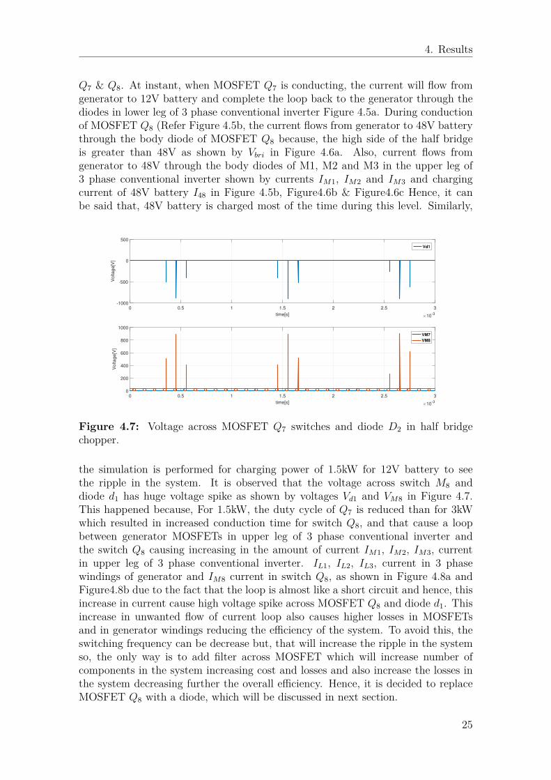
charging power of 3kW for 12V battery . . . . . . . . . . . . . . . . . 244.7 Voltage across MOSFET Q7 switches and diode D2 in half bridge
chopper. . . . . . . . . . . . . . . . . . . . . . . . . . . . . . . . . . . 254.8 Current in different components for charging power of 1.5 kW for 12V
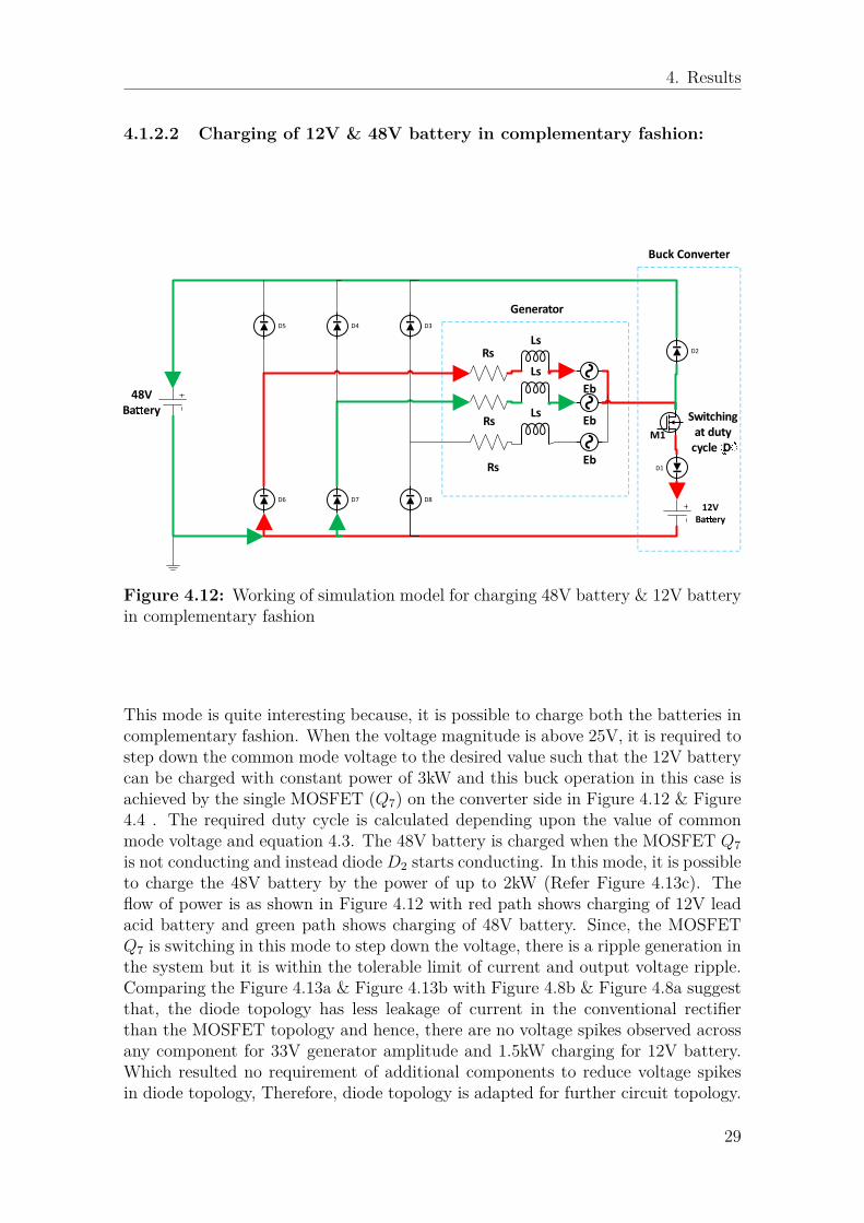
battery . . . . . . . . . . . . . . . . . . . . . . . . . . . . . . . . . . . 264.9 Simulation topology for regeneration mode using diode topology . . . 264.10 Simulation schematic for low back emf i.e. slow machine speed . . . . 274.11 Waveforms for low emf mode . . . . . . . . . . . . . . . . . . . . . . . 284.12 Working of simulation model for charging 48V battery & 12V battery
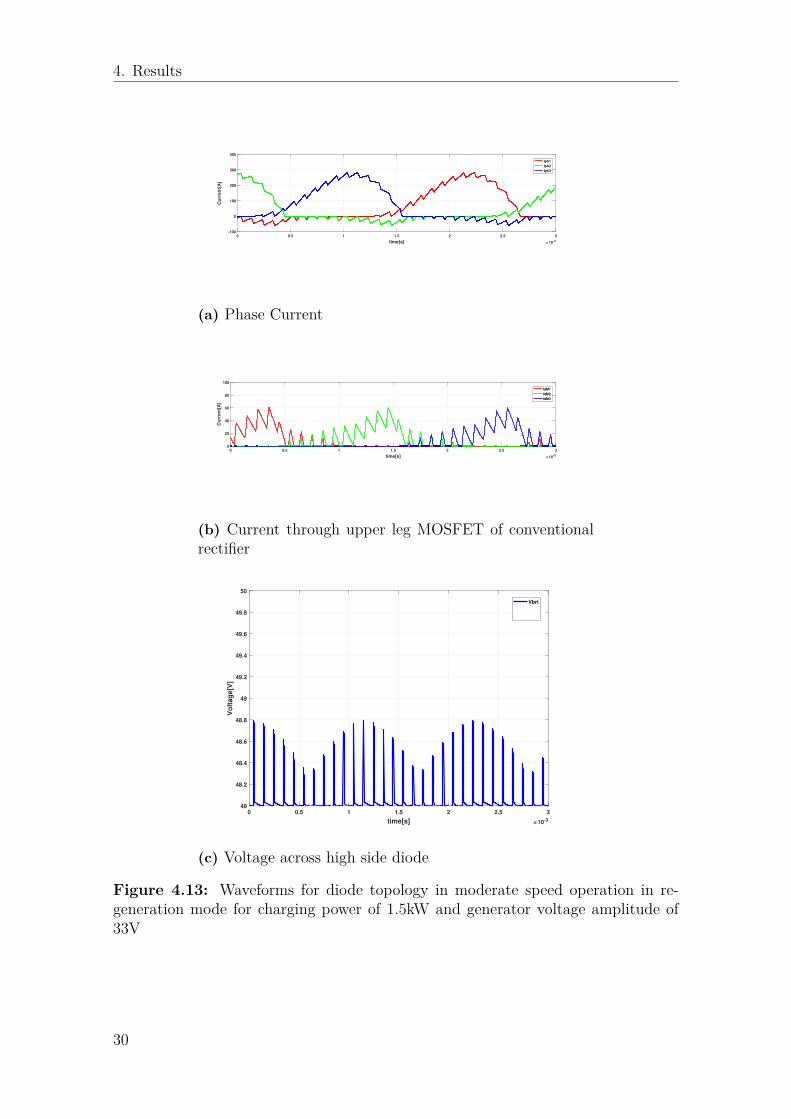
in complementary fashion . . . . . . . . . . . . . . . . . . . . . . . . 294.13 Waveforms for diode topology in moderate speed operation in re-
generation mode for charging power of 1.5kW and generator voltageamplitude of 33V . . . . . . . . . . . . . . . . . . . . . . . . . . . . . 30
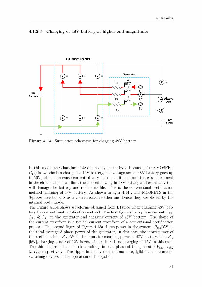
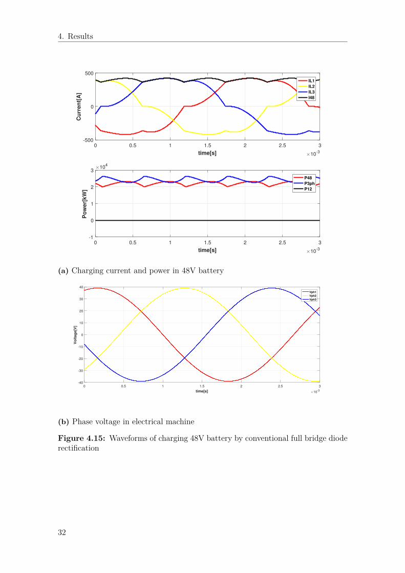
4.14 Simulation schematic for charging 48V battery . . . . . . . . . . . . . 314.15 Waveforms of charging 48V battery by conventional full bridge diode
rectification . . . . . . . . . . . . . . . . . . . . . . . . . . . . . . . . 32
xi
List of Figures
4.16 Summary of Regeneration mode with diode topology . . . . . . . . . 334.17 Electrical schematic in motoring mode for charging 12V battery . . . 344.18 Working strategy in Motoring mode . . . . . . . . . . . . . . . . . . . 354.19 For 20k power in electric motor . . . . . . . . . . . . . . . . . . . . . 374.20 For 12V battery 20k electric motor power . . . . . . . . . . . . . . . 374.21 For 5k power in electric motor . . . . . . . . . . . . . . . . . . . . . . 374.22 For 12V battery 5k electric motor power . . . . . . . . . . . . . . . . 374.23 Fft of phase currents in EESM 20kW, for charging power of 3kW for
12V battery . . . . . . . . . . . . . . . . . . . . . . . . . . . . . . . . 384.24 For 12V battery with capacitor 5kW electric motor power . . . . . . 394.25 Working strategy for New Integrated charger topology in idle mode . 404.26 For 12V battery in idle mode of machine operation . . . . . . . . . . 414.27 Ripple Current comparison for different switching strategies in idle
mode . . . . . . . . . . . . . . . . . . . . . . . . . . . . . . . . . . . 424.28 Voltage ripple comparison for different switching strategies in idle
mode . . . . . . . . . . . . . . . . . . . . . . . . . . . . . . . . . . . 43
xii

List of Tables
3.1 Table showing all the parameters used to simulate the Integratedcharger topology in LTspice . . . . . . . . . . . . . . . . . . . . . . . 18
5.1 Summary of the thesis . . . . . . . . . . . . . . . . . . . . . . . . . . 45
xiii

List of Tables
xiv
1Introduction
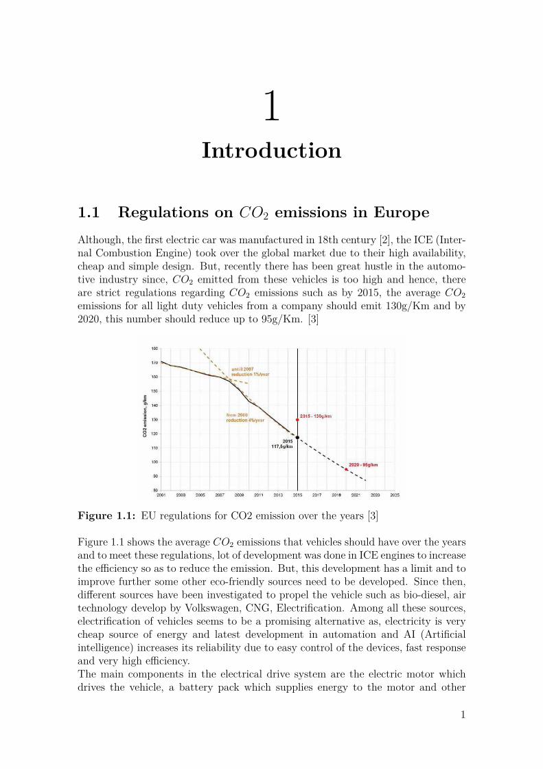
1.1 Regulations on CO2 emissions in EuropeAlthough, the first electric car was manufactured in 18th century [2], the ICE (Inter-nal Combustion Engine) took over the global market due to their high availability,cheap and simple design. But, recently there has been great hustle in the automo-tive industry since, CO2 emitted from these vehicles is too high and hence, thereare strict regulations regarding CO2 emissions such as by 2015, the average CO2emissions for all light duty vehicles from a company should emit 130g/Km and by2020, this number should reduce up to 95g/Km. [3]
Figure 1.1: EU regulations for CO2 emission over the years [3]
Figure 1.1 shows the average CO2 emissions that vehicles should have over the yearsand to meet these regulations, lot of development was done in ICE engines to increasethe efficiency so as to reduce the emission. But, this development has a limit and toimprove further some other eco-friendly sources need to be developed. Since then,different sources have been investigated to propel the vehicle such as bio-diesel, airtechnology develop by Volkswagen, CNG, Electrification. Among all these sources,electrification of vehicles seems to be a promising alternative as, electricity is verycheap source of energy and latest development in automation and AI (Artificialintelligence) increases its reliability due to easy control of the devices, fast responseand very high efficiency.The main components in the electrical drive system are the electric motor whichdrives the vehicle, a battery pack which supplies energy to the motor and other
1
1. Introduction
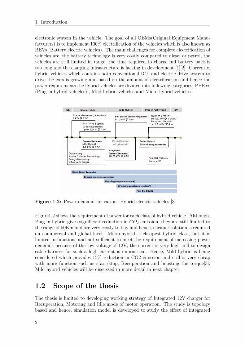
electronic system in the vehicle. The goal of all OEMs(Original Equipment Manu-facturers) is to implement 100% electrification of the vehicles which is also known asBEVs (Battery electric vehicles). The main challenges for complete electrification ofvehicles are, the battery technology is very costly compared to diesel or petrol, thevehicles are still limited in range, the time required to charge full battery pack istoo long and the charging infrastructure is lacking in development [1][2]. Currently,hybrid vehicles which contains both conventional ICE and electric drive system todrive the cars is growing and based on the amount of electrification and hence thepower requirements the hybrid vehicles are divided into following categories, PHEVs(Plug in hybrid vehicles) , Mild hybrid vehicles and Micro hybrid vehicles.
Figure 1.2: Power demand for various Hybrid electric vehicles [3]
Figure1.2 shows the requirement of power for each class of hybrid vehicle. Although,Plug-in hybrid gives significant reduction in CO2 emission, they are still limited tothe range of 50Km and are very costly to buy and hence, cheaper solution is requiredon commercial and global level. Micro-hybrid is cheapest hybrid class, but it islimited in functions and not sufficient to meet the requirement of increasing powerdemands because of the low voltage of 12V, the current is very high and to designcable harness for such a high current is impractical. Hence, Mild hybrid is beingconsidered which provides 15% reduction in CO2 emission and still is very cheapwith more function such as start/stop, Recuperation and boosting the torque[3].Mild hybrid vehicles will be discussed in more detail in next chapter.
1.2 Scope of the thesisThe thesis is limited to developing working strategy of Integrated 12V charger forRecuperation, Motoring and Idle mode of motor operation. The study is topologybased and hence, simulation model is developed to study the effect of integrated
2
1. Introduction
charging on the system. This effect is quantified by measuring the efficiency andalso the ripple content in the charging system for different modes of motor operation.
1.3 Methods and tools used in this thesis:The objective of this thesis is to check the feasibility to integrate charging of 12Vbattery with 48V drivetrain. Hence, it was decided to use simulation method toanalyze the three modes of motor operation as required by VOLVO cars. Differ-ent modes of operation were simulated by developing an equivalent electrical circuitmodel of different components for example, battery pack in the model is representedby a dc voltage source and a series internal resistance, ISG (Integrated Starter/Gen-erator) machine is represented by a generic simplified RLE electrical machine modeletc. The ratings of these components were based on input from VOLVO cars, De-sign project on ‘Design of 48V 3-phase Inverter’ and PHD thesis on Developing 48VEESM (Electrically Excited Synchronous Machine) at Chalmers university of tech-nology. The specifications of rating for various components are provided in 3.1LTspice is used as a simulation tool for this thesis; the reason is that, it’s a freelicensed software, easy to use, availability of big library of various components avail-able freely on respective website of component company; the data can be easilyexported to MATLAB for post-processing. It is also easy to form a whole system(in this case mild hybrid system) by integrating other small sub-systems (like in-verter, electric machine etc.), Transitioning between different modes of operation ofmotor is quick and easy. The conclusions drawn are strictly based on simulationresults.
1.4 Organization of ThesisChapter 1 consists of Introduction explaining the need to implement electrical driv-etrain considering the demand to reduce the CO2 emission for coming years, it alsodescribes the scope of the thesis and methods used to achieve the objective of thethesis. Chapter 2 includes Description of 48V Mild hybrid system with differentmodes of operation it also describe the need to implement dual voltage energy stor-age system for hybrid vehicles and the need to integrate 12V charging which is themain objective of this thesis. Chapter 3 describes the different topologies whichare considered for this thesis and also introduces the new topology developed forthis thesis with simulated model description and defining all the parameters used tosimulate the model. Chapter 4 is divided into three parts, each shows the simulationresults obtained for different modes of operation for new integrated 12V chargingtopology and also discuss the results. Chapter 5 contains the conclusion based uponthe results obtained and the future work for the thesis.
3

1. Introduction
4
2Mild Hybrid vehicle systems
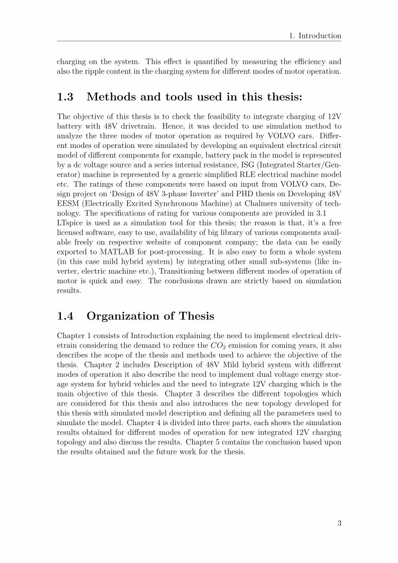
After the huge commercial success of Toyota Prius all major OEM companies inautomobile started developing mild hybrid cars[2]. The major reasons for this tran-sition were the strict rules by the governments on reducing carbon emission, under-developed battery technologies which resulted in costly Plug in hybrids (PHEVs)and Battery electric vehicles (BEVs) and also insufficient availability of charginginfrastructure. Mild hybrid technology reduces carbon emission by 15% and alsovery cheap compared to PHEVs and BEVs due to less number of components inthe powertrain. It operates at a voltage of 48V dc which is four times more than12V systems that allows higher power and less thick cable harnesses. Furthermore,the voltage is less than 60V dc which is considered as threshold for the dc voltagevalue for automotive application that prevents any need of additional isolation thus,saving space and cost of the system. Figure 2.1 shows the main components of a
48V Lithium-ion BatteryPower
ElectronicsISG
Internal Combustion Engine(ICE)
Clutch
To the Wheels
DC/DC converter 12V Lead acid battery 12V board net
Figure 2.1: Mild hybrid dual voltage system architecture
power train in a typical mild hybrid car. The wheels can be propelled by both ICEand electric machine and hence, the CO2 emission can be reduced by sharing theload. The Electric motor and ICE are coupled to each other directly and hence thisarrangement is called Integrated Starter/Generator(ISG). The name indicates that,the machine is capable of starting the engine as well as recuperating brake energyto charge the lithium ion battery pack thus saving the space from alternator. Powerelectronics is required to convert the dc power of battery into suitable ac power forthe ISG and also a control unit to constantly monitor the requested torque inputand control accordingly the torque output by using torque encoder or by convertingrequested torque into equivalent current and voltage by power control unit of thevehicle.
5
2. Mild Hybrid vehicle systems
2.1 Different modes of motor operation in Mildhybrid vehicles
2.1.1 Start/Stop and Torque assistance mode
48V Lithium-ion
Baery
Power
ElectronicsISG
Internal Combuson Engine(ICE)
To the Wheels
DC/DC converter12V Lead acid
baery12V board net
Clutch closed
- Charging
Power
-Supplying
Power
Figure 2.2: Schematic of operation in start/stop and torque assisting for Mildhybrid system
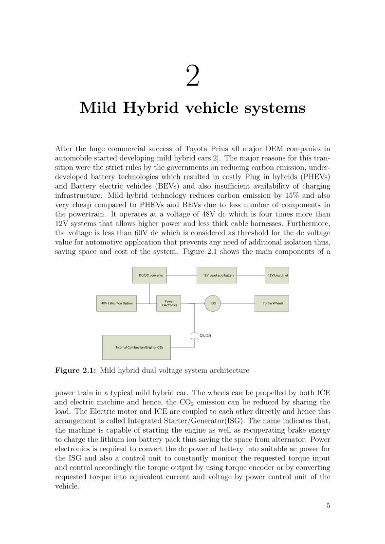
The significant reduction of CO2 emission for a mild hybrid systems can be achievedin these two operation because, during these two operations, engine needs a veryhigh torque at low speeds and ICE has a drawback of having very low efficiencyat lower speed therefore, to achieve required amount of torque, it consumes veryhigh quantity of fuel causing higher CO2 emissions. This can be achieved by usingan electric motor supplied by a lithium ion battery which can generate very hightorques at much higher efficiency than ICE. So, the engine is started by using anelectrical system and so as shown in the Figure 2.2, battery will supply the requiredamount of energy.The torque assistance is required when the car is climbing a slope.In this case, there is a limit on torque provided by ICE and the excess torque issupplied by the electrical system reducing the consumption of fuel and reducing thecarbon emission. Figure 2.2 shows that, during torque assistance the load is sharedby ICE and electrical system. ISGs operate at higher power of 15kW-20kW, referto figure 1.2 and hence, it is also possible to have electrical steering for very shortrange which further reduces the carbon emission when driving in the cities[3]. In aelectrical simulation model, this mode can be simulated by using 48V battery as adc source supplying a RLE load which represents electrical machine and an invertermodel which converts dc voltage of 48V battery into ac voltage input for the motor.
2.1.2 Recuperation mode(Regenerative Braking)This mode is used to charge the 48V battery by using ISG, this can be done byusing electrical braking to brake the wheels at high speeds by applying negative
6
2. Mild Hybrid vehicle systems
48V Lithium-ion
Battery
Power
ElectronicsISG
Internal Combustion Engine(ICE)
To the Wheels
DC/DC
converter
12V Lead
acid battery
12V board
net
Clutch open
-Charging Power
-Supplying
Power
Figure 2.3: Schematic for recuperation mode in mild hybrid system
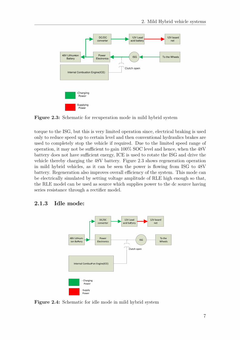
torque to the ISG, but this is very limited operation since, electrical braking is usedonly to reduce speed up to certain level and then conventional hydraulics brakes areused to completely stop the vehicle if required. Due to the limited speed range ofoperation, it may not be sufficient to gain 100% SOC level and hence, when the 48Vbattery does not have sufficient energy, ICE is used to rotate the ISG and drive thevehicle thereby charging the 48V battery. Figure 2.3 shows regeneration operationin mild hybrid vehicles, as it can be seen the power is flowing from ISG to 48Vbattery. Regeneration also improves overall efficiency of the system. This mode canbe electrically simulated by setting voltage amplitude of RLE high enough so that,the RLE model can be used as source which supplies power to the dc source havingseries resistance through a rectifier model.
2.1.3 Idle mode:
48V Lithium-
ion Baery
Power
ElectronicsISG
Internal Combuson Engine(ICE)
To the
Wheels
DC/DC
converter
12V Lead
acid baery
12V board
net
Clutch open
- Charging
Power
-Supply
Power
Figure 2.4: Schematic for idle mode in mild hybrid system
7
2. Mild Hybrid vehicle systems
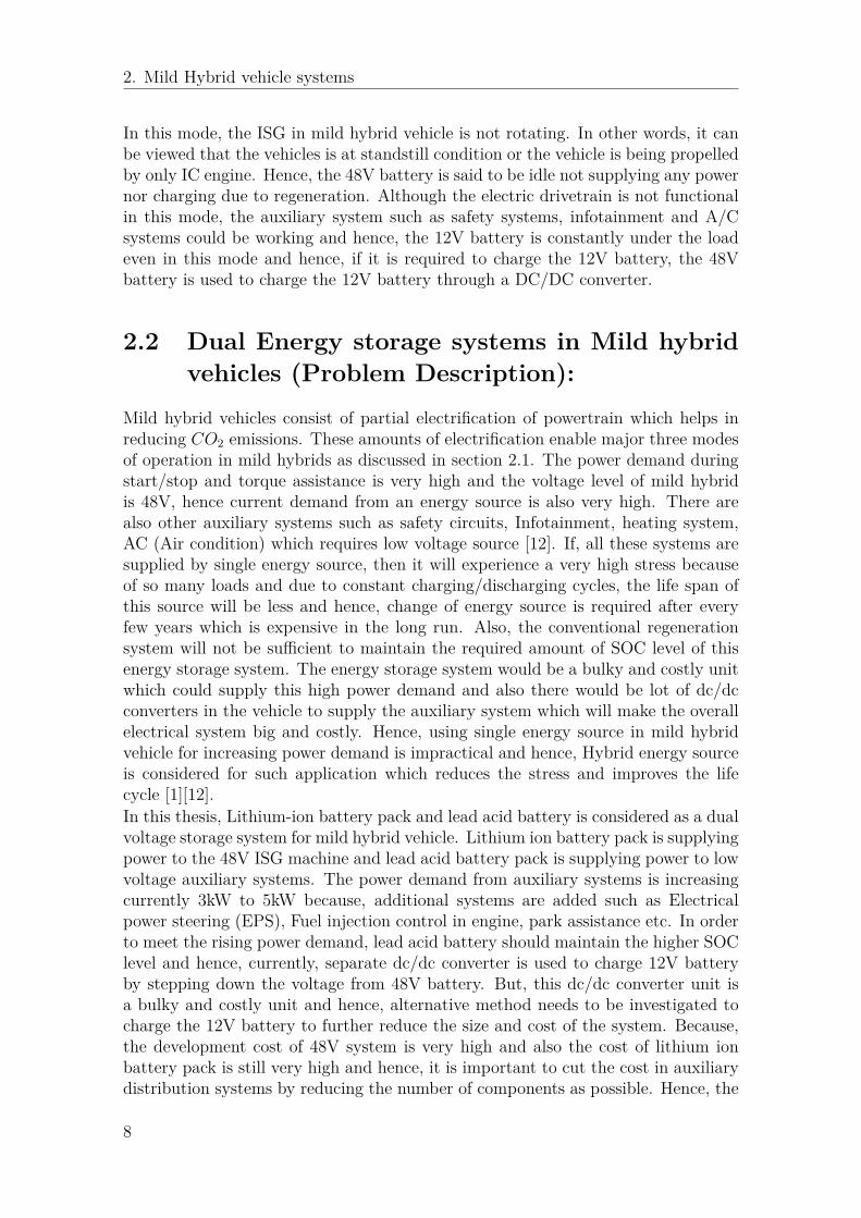
In this mode, the ISG in mild hybrid vehicle is not rotating. In other words, it canbe viewed that the vehicles is at standstill condition or the vehicle is being propelledby only IC engine. Hence, the 48V battery is said to be idle not supplying any powernor charging due to regeneration. Although the electric drivetrain is not functionalin this mode, the auxiliary system such as safety systems, infotainment and A/Csystems could be working and hence, the 12V battery is constantly under the loadeven in this mode and hence, if it is required to charge the 12V battery, the 48Vbattery is used to charge the 12V battery through a DC/DC converter.
2.2 Dual Energy storage systems in Mild hybridvehicles (Problem Description):
Mild hybrid vehicles consist of partial electrification of powertrain which helps inreducing CO2 emissions. These amounts of electrification enable major three modesof operation in mild hybrids as discussed in section 2.1. The power demand duringstart/stop and torque assistance is very high and the voltage level of mild hybridis 48V, hence current demand from an energy source is also very high. There arealso other auxiliary systems such as safety circuits, Infotainment, heating system,AC (Air condition) which requires low voltage source [12]. If, all these systems aresupplied by single energy source, then it will experience a very high stress becauseof so many loads and due to constant charging/discharging cycles, the life span ofthis source will be less and hence, change of energy source is required after everyfew years which is expensive in the long run. Also, the conventional regenerationsystem will not be sufficient to maintain the required amount of SOC level of thisenergy storage system. The energy storage system would be a bulky and costly unitwhich could supply this high power demand and also there would be lot of dc/dcconverters in the vehicle to supply the auxiliary system which will make the overallelectrical system big and costly. Hence, using single energy source in mild hybridvehicle for increasing power demand is impractical and hence, Hybrid energy sourceis considered for such application which reduces the stress and improves the lifecycle [1][12].In this thesis, Lithium-ion battery pack and lead acid battery is considered as a dualvoltage storage system for mild hybrid vehicle. Lithium ion battery pack is supplyingpower to the 48V ISG machine and lead acid battery pack is supplying power to lowvoltage auxiliary systems. The power demand from auxiliary systems is increasingcurrently 3kW to 5kW because, additional systems are added such as Electricalpower steering (EPS), Fuel injection control in engine, park assistance etc. In orderto meet the rising power demand, lead acid battery should maintain the higher SOClevel and hence, currently, separate dc/dc converter is used to charge 12V batteryby stepping down the voltage from 48V battery. But, this dc/dc converter unit isa bulky and costly unit and hence, alternative method needs to be investigated tocharge the 12V battery to further reduce the size and cost of the system. Because,the development cost of 48V system is very high and also the cost of lithium ionbattery pack is still very high and hence, it is important to cut the cost in auxiliarydistribution systems by reducing the number of components as possible. Hence, the
8

2. Mild Hybrid vehicle systems
objective of this thesis is to investigate the feasibility of integrating charging of 12Vbattery with 48V drivetrain which will make the overall system compact and costeffective. In the next chapter various topologies are discussed and a new topologyis adapted to meet the required power increasing demand of the auxiliary system.
9

2. Mild Hybrid vehicle systems
10
3Integrated Charger topologies
The following conditions were set by VOLVO cars to design the integrated chargingtopology:
• The topology should be designed for mild hybrid dual voltage vehicle applica-tions.
• The topology should be able to charge the 12V battery continuously, duringidle mode, regeneration mode and motoring mode.
• The topology should consist of minimum number of components so that, theoverall packaging of drivetrain should be compact and cost effective than thepresent separate dc/dc architecture.
• The peak power for charging the 12V battery is 3kW.
• The 12V battery in this application is only used to supply the auxiliary loadsin the vehicle and hence, it should not be possible to supply the ISG from 12Vbattery.
Based upon the conditions set for the development of the topology, the major chal-lenge is to find the topology which will fulfill the requirement on continuous op-eration of charging and at the same time it is compact and have less number ofcomponents. Hence, it is decided to develop a single circuit which can have thepossibility to charge the 12V battery in all three modes of operation to keep the lessnumber of components and to keep the circuit simple. To simplify the development,it is decided to first incorporate the charging for motor mode and regeneration modesince, lot of papers are found which developed charging strategy for these modes ofmotor operation for dual voltage vehicle applications.Various topologies were investigated for integrated charging concept; such as DualAlternator topology based on a Master thesis done on Dual Alternator topologyand Alternator topology with center tap connection is based on PHD thesis. Dualalternator topology consisted of an alternator with two voltage winding, one for thehigh voltage and other for the low voltage. And because of this arrangement, only ahalf bridge rectifier was needed to charge the 12V battery along with the full waveconventional rectifier for 36V battery [6].The other topology which is considered was the ‘Star point alternator topology withcenter tap connection’; It consists of connecting 12V battery between the star pointof alternator and common ground of the electrical drivetrain system. The advantage
11
3. Integrated Charger topologies
of this system is that, the charging of either batteries is dependent on the alterna-tor speed and hence, a control unit was placed which measures the voltage at starpoint of the alternator and when the voltage amplitude is sufficient to charge the12V battery i.e. at low speed by 4.1, it will enable the charging of 12V battery bycontrolling the MOSFET switches. When the voltage is higher i.e. at high speeds,the controller will disable the charging of 12V battery and then the 36V battery willbe charged by conventional full wave rectifier circuit [4].The final topology which is considered for the thesis is ‘The Novel Star point invertertopology’ for Dual voltage 48V/12V Mild hybrid application. This topology is usedto integrate the charging of 12V battery during motoring mode of ISG operation.The charging of 12V battery is achieved by using the common mode voltage of theinverter. Also, in this topology, the 12V battery is connected between the star pointof the machine and the negative terminal of the 48V battery, the common neutralpoint for inverter and the 48V battery and the charging is done by the implement-ing a half bridge chopper circuit which is used to chop off the excess common modevoltage[5].
3.1 Challenges in developing the new integrateddual voltage charging topology:
Dual Alternator concept was not considered further because, it requires having anadditional stator winding in the motor housing which would result in increased in sizeof electric machine and VOLVO cars, did not want to increase the size of motor due tospace constraints. To simplify the development, it was decided to first incorporatethe charging for motor mode and regeneration mode since, Star point alternatortopology and The novel star point inverter topology discussed about the integratedcharging of 12V battery for regeneration mode and motoring mode respectively andhence, these two topologies were considered as a base for this thesis. The thesiswork started with developing a simulation model in LTspice based on novel starpoint inverter topology which is based on common mode voltage, Hence, the modelconsisted of 48V dc source, 3-phase inverter and a RLE machine model. Initially, thefeasibility of model is checked for regeneration mode and then it is checked for formotoring mode. The inverter in motoring mode is operated by using SINE trianglemodulation (STM) because, it is quick and simple to implement this pwm techiniqueand since, the topology is based on using common mode voltage of the motor. Itis important to understand the basics of common mode voltage and how it can becontrolled by using SINE triangle modulation.
3.2 Common Mode Voltage:
Common mode voltage (Vcm) is voltage which is measured in between the star pointof the 3-phase rotating machine with respect to the ground of the traction system.Although, the ground point is not present in the practical system, since electricaldrive system is kept floating for safety reasons, But, for mild hybrid vehicles, there is
12
3. Integrated Charger topologies
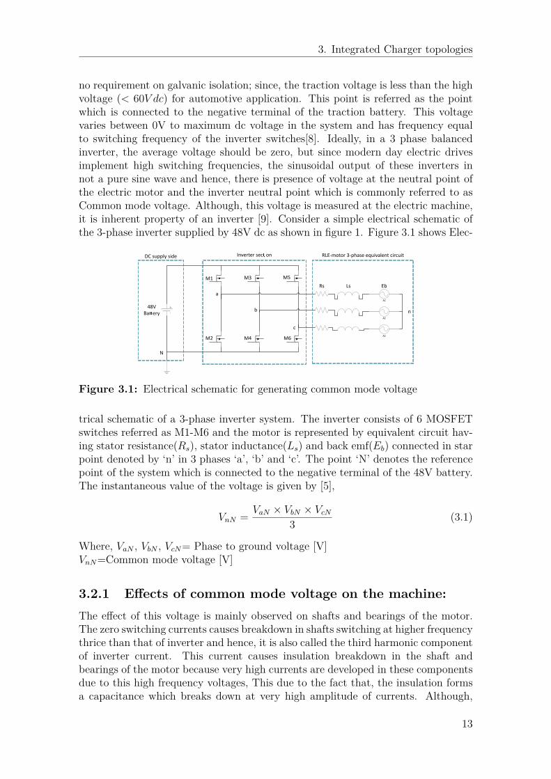
no requirement on galvanic isolation; since, the traction voltage is less than the highvoltage (< 60V dc) for automotive application. This point is referred as the pointwhich is connected to the negative terminal of the traction battery. This voltagevaries between 0V to maximum dc voltage in the system and has frequency equalto switching frequency of the inverter switches[8]. Ideally, in a 3 phase balancedinverter, the average voltage should be zero, but since modern day electric drivesimplement high switching frequencies, the sinusoidal output of these inverters innot a pure sine wave and hence, there is presence of voltage at the neutral point ofthe electric motor and the inverter neutral point which is commonly referred to asCommon mode voltage. Although, this voltage is measured at the electric machine,it is inherent property of an inverter [9]. Consider a simple electrical schematic ofthe 3-phase inverter supplied by 48V dc as shown in figure 1. Figure 3.1 shows Elec-
AC
AC
AC
48V
Baery
a
b
c
N
n
Rs Ls Eb
M1
M2
M3
M4
M5
M6
DC supply side Inverter secon RLE-motor 3-phase equivalent circuit
Figure 3.1: Electrical schematic for generating common mode voltage
trical schematic of a 3-phase inverter system. The inverter consists of 6 MOSFETswitches referred as M1-M6 and the motor is represented by equivalent circuit hav-ing stator resistance(Rs), stator inductance(Ls) and back emf(Eb) connected in starpoint denoted by ‘n’ in 3 phases ‘a’, ‘b’ and ‘c’. The point ‘N’ denotes the referencepoint of the system which is connected to the negative terminal of the 48V battery.The instantaneous value of the voltage is given by [5],
VnN = VaN × VbN × VcN
3 (3.1)
Where, VaN , VbN , VcN= Phase to ground voltage [V]VnN=Common mode voltage [V]
3.2.1 Effects of common mode voltage on the machine:The effect of this voltage is mainly observed on shafts and bearings of the motor.The zero switching currents causes breakdown in shafts switching at higher frequencythrice than that of inverter and hence, it is also called the third harmonic componentof inverter current. This current causes insulation breakdown in the shaft andbearings of the motor because very high currents are developed in these componentsdue to this high frequency voltages, This due to the fact that, the insulation formsa capacitance which breaks down at very high amplitude of currents. Although,
13
3. Integrated Charger topologies
high frequencies are preferred for the inverter to reduce the size and cost of thecomponents, it causes formation of high currents because [10],
ic = C × dV
dt(3.2)
There are various methods to mitigate the effect of common mode voltage, but, themain objective of this thesis is to utilize this common mode voltage to charge 12Vbattery and hence, it is important to control the amplitude of this voltage to therequired constant value. One such method involves controlling the instantaneousvalue of common mode voltage which is discussed in next section.
3.2.2 Controlling instantaneous value of common mode volt-age by using sine triangle pwm technique:
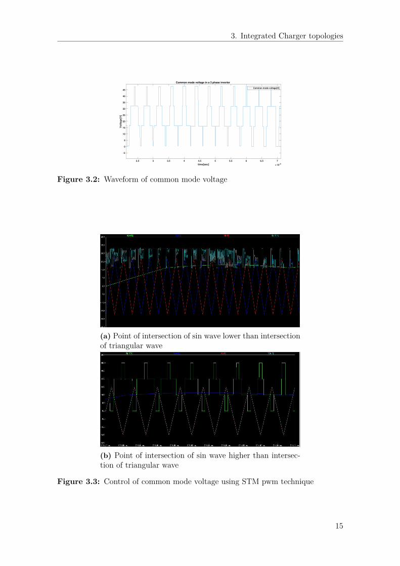
In STM technique of pwm,the pwm signal for EM is generated by comparing refer-ence sine wave with the triangle waveform, and the switching of MOSFETs is decidedby the instant at which the reference sine wave crosses the triangular waveform andthe condition is set such that, the amplitude is compared of the two waveforms andthe command is send depending upon the condition. For example, if the voltageamplitude of sine wave is greater than triangular wave then the, mosfet should turnON or Turn off. This is the basic logic behind the generation of sinusoidal output fora inverter. [11] In this method, reference sine wave is compared with two triangularwaveforms and the condition is set in LTspice such that, when the amplitude of sinewave is greater than the amplitude of both the triangular waves then the switches inupper leg of the inverter should turn ON and the Switch in lower leg of same phaseshould turn off and the dead time between these two mosfets is decided by the delaybetween these two triangular waveforms. Now, it is proved in the paper[7] that theinstantaneous value of the common mode voltage is dependent on the point of in-tersection of two triangle waveforms and the point at which the sine wave intersectthe triangular waveform, This control is divided into two levels;
• When point of intersection of sine wave with triangular waves is far lower thanpoint of intersection of triangular waves as shown in figure 3.3a
• When point of intersection of sine wave is higher than point of intersection oftriangular waves as shown in figure 3.3b
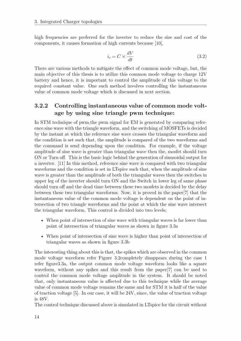
The interesting thing about this is that, the spikes which are observed in the commonmode voltage waveform refer Figure 3.2completely disappears during the case 1refer figure3.3a, the output common mode voltage waveform looks like a squarewaveform, without any spikes and this result from the paper[7] can be used tocontrol the common mode voltage amplitude in the system. It should be notedthat, only instantaneous value is affected due to this technique while the averagevalue of common mode voltage remains the same and for STM it is half of the valueof traction voltage [5]. In our case, it will be 24V, since, the value of traction voltageis 48V.The control technique discussed above is simulated in LTspice for the circuit without
14
3. Integrated Charger topologies
2.5 3 3.5 4 4.5 5 5.5 6 6.5 7
time[sec] 10-4
-5
0
5
10
15
20
25
30
35
40
45
Vo
lta
ge
[V]
Common mode voltage in a 3 phase inverter
Common mode voltage[V]
Figure 3.2: Waveform of common mode voltage
(a) Point of intersection of sin wave lower than intersectionof triangular wave
(b) Point of intersection of sin wave higher than intersec-tion of triangular wave
Figure 3.3: Control of common mode voltage using STM pwm technique
15
3. Integrated Charger topologies
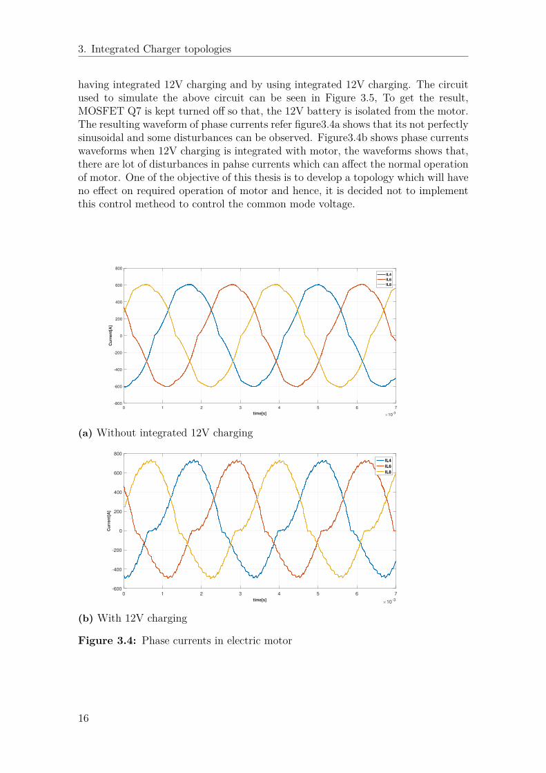
having integrated 12V charging and by using integrated 12V charging. The circuitused to simulate the above circuit can be seen in Figure 3.5, To get the result,MOSFET Q7 is kept turned off so that, the 12V battery is isolated from the motor.The resulting waveform of phase currents refer figure3.4a shows that its not perfectlysinusoidal and some disturbances can be observed. Figure3.4b shows phase currentswaveforms when 12V charging is integrated with motor, the waveforms shows that,there are lot of disturbances in pahse currents which can affect the normal operationof motor. One of the objective of this thesis is to develop a topology which will haveno effect on required operation of motor and hence, it is decided not to implementthis control metheod to control the common mode voltage.
0 1 2 3 4 5 6 7
time[s] 10-3
-800
-600
-400
-200
0
200
400
600
800
Cu
rren
t[A
]
IL4
IL6
IL8
(a) Without integrated 12V charging
0 1 2 3 4 5 6 7
time[s]10
-3
-600
-400
-200
0
200
400
600
800
Cu
rren
t[A
]
IL4
IL6
IL8
(b) With 12V charging
Figure 3.4: Phase currents in electric motor
16
3. Integrated Charger topologies
3.3 New Integrated charger topology circuit de-scription:
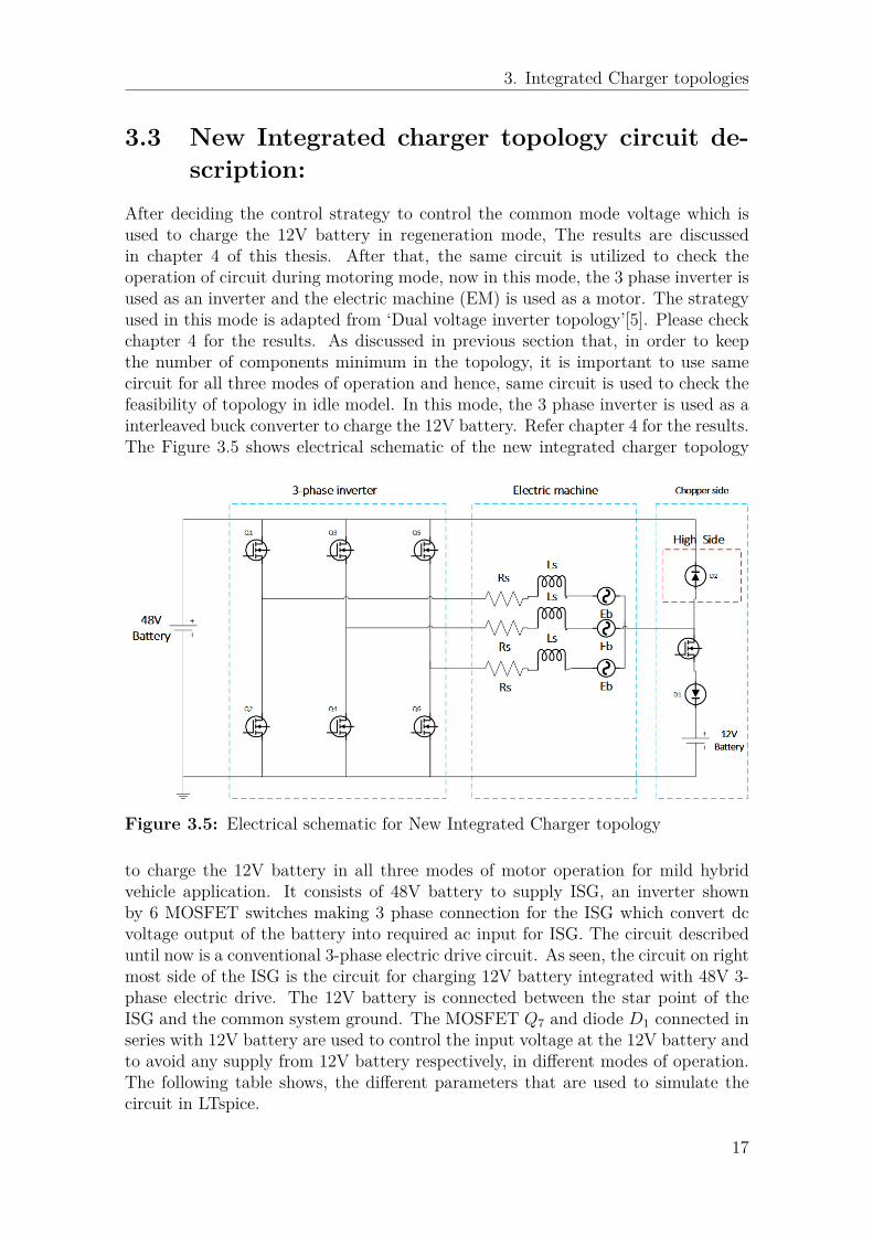
After deciding the control strategy to control the common mode voltage which isused to charge the 12V battery in regeneration mode, The results are discussedin chapter 4 of this thesis. After that, the same circuit is utilized to check theoperation of circuit during motoring mode, now in this mode, the 3 phase inverter isused as an inverter and the electric machine (EM) is used as a motor. The strategyused in this mode is adapted from ‘Dual voltage inverter topology’[5]. Please checkchapter 4 for the results. As discussed in previous section that, in order to keepthe number of components minimum in the topology, it is important to use samecircuit for all three modes of operation and hence, same circuit is used to check thefeasibility of topology in idle model. In this mode, the 3 phase inverter is used as ainterleaved buck converter to charge the 12V battery. Refer chapter 4 for the results.The Figure 3.5 shows electrical schematic of the new integrated charger topology
Figure 3.5: Electrical schematic for New Integrated Charger topology
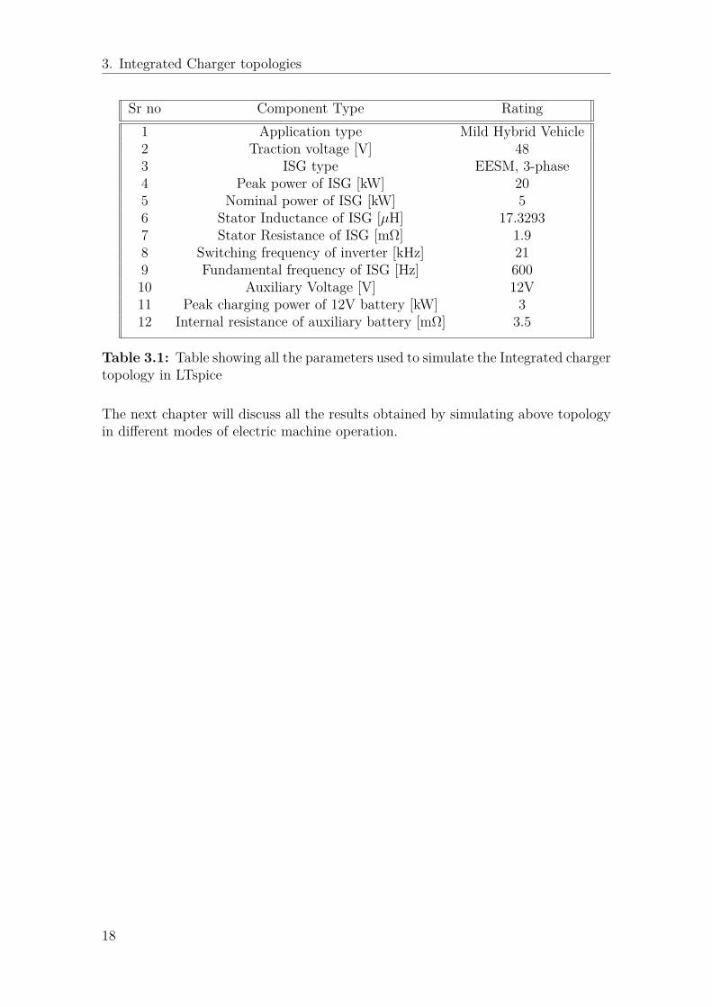
to charge the 12V battery in all three modes of motor operation for mild hybridvehicle application. It consists of 48V battery to supply ISG, an inverter shownby 6 MOSFET switches making 3 phase connection for the ISG which convert dcvoltage output of the battery into required ac input for ISG. The circuit describeduntil now is a conventional 3-phase electric drive circuit. As seen, the circuit on rightmost side of the ISG is the circuit for charging 12V battery integrated with 48V 3-phase electric drive. The 12V battery is connected between the star point of theISG and the common system ground. The MOSFET Q7 and diode D1 connected inseries with 12V battery are used to control the input voltage at the 12V battery andto avoid any supply from 12V battery respectively, in different modes of operation.The following table shows, the different parameters that are used to simulate thecircuit in LTspice.
17
3. Integrated Charger topologies
Sr no Component Type Rating1 Application type Mild Hybrid Vehicle2 Traction voltage [V] 483 ISG type EESM, 3-phase4 Peak power of ISG [kW] 205 Nominal power of ISG [kW] 56 Stator Inductance of ISG [µH] 17.32937 Stator Resistance of ISG [mΩ] 1.98 Switching frequency of inverter [kHz] 219 Fundamental frequency of ISG [Hz] 60010 Auxiliary Voltage [V] 12V11 Peak charging power of 12V battery [kW] 312 Internal resistance of auxiliary battery [mΩ] 3.5
Table 3.1: Table showing all the parameters used to simulate the Integrated chargertopology in LTspice
The next chapter will discuss all the results obtained by simulating above topologyin different modes of electric machine operation.
18
4Results
4.1 Regeneration ModeIn this chapter, the simulation results are obtained by simulating the Electricalmachine in regeneration mode. Initially, the working of simulation models will bedescribed in detail based on two types of topology, then simulation results will beshown based on different types of loading conditions for the DC/DC chopper andat different speeds. Then, the conclusion will be made depending on the obtainedresults. The two types of topologies are considered for this mode and the descriptionof both these topologies are given below,Case 1: MOSFET is used in high side of the chopper acting as freewheeling com-ponent for the switch (MOSFET Topology).Case 2: Diode is used in high side of the chopper acting as freewheeling componentfor the switch (Diode Topology).
4.1.1 Switch Topology
Q1
Q2
Q3
Q4
Q5
Q6
RsLs
Ls
Ls
Eb
Eb
Eb
Q7
D1
48V Battery
Full bridge Recti er Generator Chopper side
12V Battery
High Side
Rs
Rs
Q8
Figure 4.1: Schematic of Regeneration mode using Switch topology
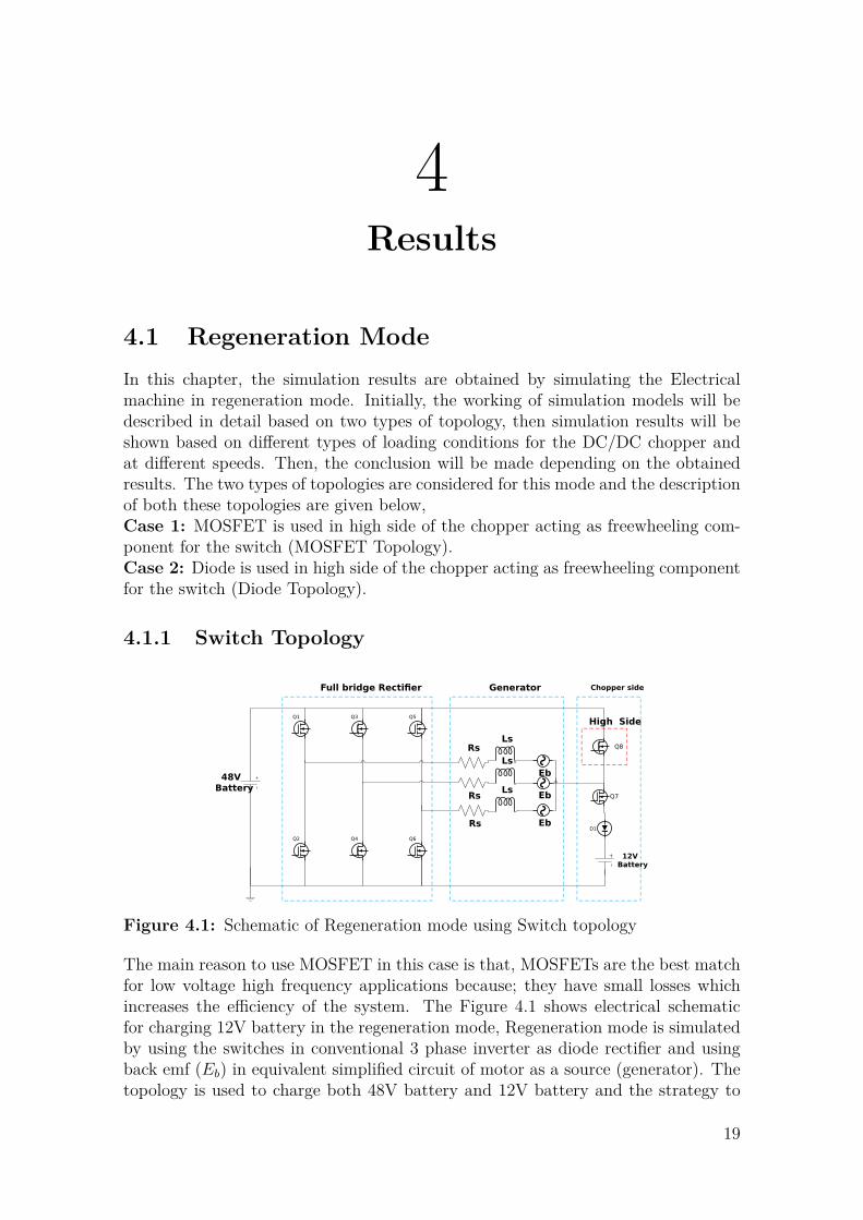
The main reason to use MOSFET in this case is that, MOSFETs are the best matchfor low voltage high frequency applications because; they have small losses whichincreases the efficiency of the system. The Figure 4.1 shows electrical schematicfor charging 12V battery in the regeneration mode, Regeneration mode is simulatedby using the switches in conventional 3 phase inverter as diode rectifier and usingback emf (Eb) in equivalent simplified circuit of motor as a source (generator). Thetopology is used to charge both 48V battery and 12V battery and the strategy to
19
4. Results
achieve this depends on the value of voltage amplitude in the generator 4.1. Thus,the regeneration mode is divided into three levels; low speed generation, moderatespeed generation and high-speed generation. The three levels of regeneration modeare explained in following sections. This strategy is based on[4]
4.1.1.1 Low speed generation:
In this level, the generator speed is considered very less generating back emf of verylow amplitude in the range of 18V-24V sufficient enough to charge the 12V Battery.The back emf is directly proportional to the generator speed by the equation,
Eb = kbω (4.1)
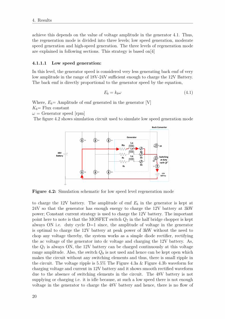
Where, Eb= Amplitude of emf generated in the generator [V]Kb= Flux constantω = Generator speed [rpm]The figure 4.2 shows simulation circuit used to simulate low speed generation mode
Rs
Ls
Ls
Ls
Eb
Eb
EbD1
48V
Baery
12V
Baery
Rs
Rs
D3D4D5
D6 D7 D8
Generator
Switching
at duty
cycle DQ7
Buck Converter
Q8
Figure 4.2: Simulation schematic for low speed level regeneration mode
to charge the 12V battery. The amplitude of emf Eb in the generator is kept at24V so that the generator has enough energy to charge the 12V battery at 3kWpower; Constant current strategy is used to charge the 12V battery. The importantpoint here to note is that the MOSFET switch Q7 in the half bridge chopper is keptalways ON i.e. duty cycle D=1 since, the amplitude of voltage in the generatoris optimal to charge the 12V battery at peak power of 3kW without the need tochop any voltage thereby, the system works as a simple diode rectifier, rectifyingthe ac voltage of the generator into dc voltage and charging the 12V battery. As,the Q7 is always ON, the 12V battery can be charged continuously at this voltagerange amplitude. Also, the switch Q8 is not used and hence can be kept open whichmakes the circuit without any switching elements and thus, there is small ripple inthe circuit. The voltage ripple is 5.5% The Figure 4.3a & Figure 4.3b waveform forcharging voltage and current in 12V battery and it shows smooth rectified waveformdue to the absence of switching elements in the circuit. The 48V battery is notsupplying or charging i.e. it is idle because, at such a low speed there is not enoughvoltage in the generator to charge the 48V battery and hence, there is no flow of
20
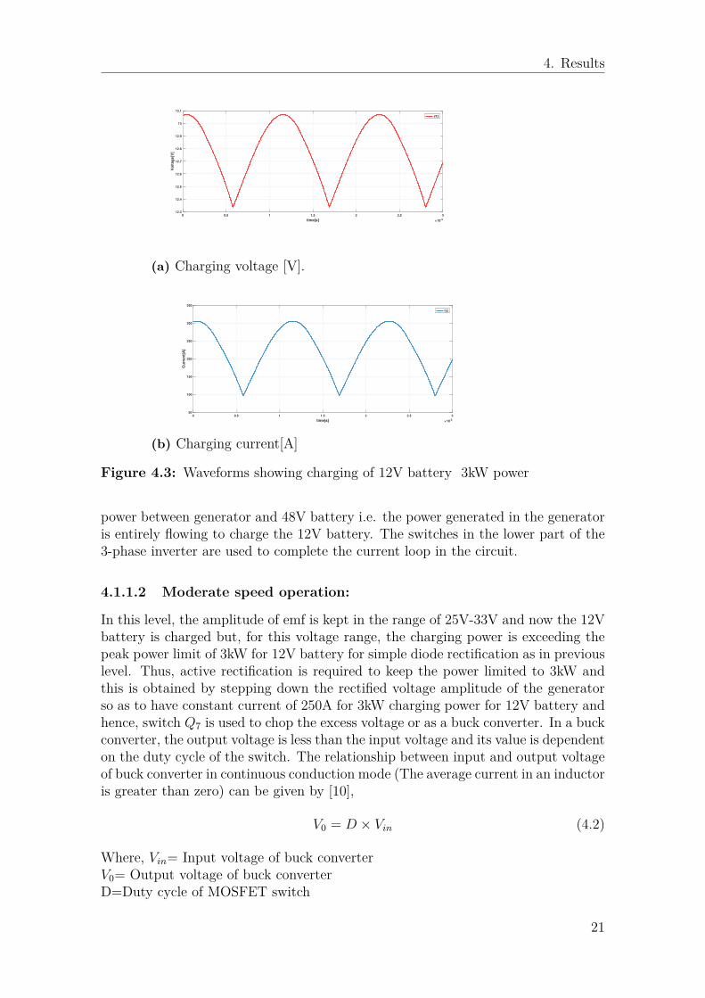
4. Results
0 0.5 1 1.5 2 2.5 3
time[s] 10-3
12.3
12.4
12.5
12.6
12.7
12.8
12.9
13
13.1
Vo
lta
ge
[V]
V12
(a) Charging voltage [V].
0 0.5 1 1.5 2 2.5 3
time[s] 10-3
50
100
150
200
250
300
350
Cu
rre
nt[
A]
I12
(b) Charging current[A]
Figure 4.3: Waveforms showing charging of 12V battery 3kW power
power between generator and 48V battery i.e. the power generated in the generatoris entirely flowing to charge the 12V battery. The switches in the lower part of the3-phase inverter are used to complete the current loop in the circuit.
4.1.1.2 Moderate speed operation:
In this level, the amplitude of emf is kept in the range of 25V-33V and now the 12Vbattery is charged but, for this voltage range, the charging power is exceeding thepeak power limit of 3kW for 12V battery for simple diode rectification as in previouslevel. Thus, active rectification is required to keep the power limited to 3kW andthis is obtained by stepping down the rectified voltage amplitude of the generatorso as to have constant current of 250A for 3kW charging power for 12V battery andhence, switch Q7 is used to chop the excess voltage or as a buck converter. In a buckconverter, the output voltage is less than the input voltage and its value is dependenton the duty cycle of the switch. The relationship between input and output voltageof buck converter in continuous conduction mode (The average current in an inductoris greater than zero) can be given by [10],
V0 = D × Vin (4.2)
Where, Vin= Input voltage of buck converterV0= Output voltage of buck converterD=Duty cycle of MOSFET switch
21
4. Results
DC Source
S L
DC0 Load
Input side Buck circuit topology Output side
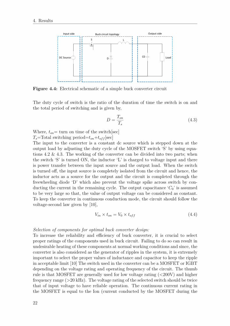
Figure 4.4: Electrical schematic of a simple buck converter circuit
The duty cycle of switch is the ratio of the duration of time the switch is on andthe total period of switching and is given by,
D = Ton
Ts
(4.3)
Where, ton= turn on time of the switch[sec]Ts=Total switching period=ton+toff [sec]The input to the converter is a constant dc source which is stepped down at theoutput load by adjusting the duty cycle of the MOSFET switch ‘S’ by using equa-tions 4.2 & 4.3. The working of the converter can be divided into two parts; whenthe switch ‘S’ is turned ON, the inductor ‘L’ is charged to voltage input and thereis power transfer between the input source and the output load. When the switchis turned off, the input source is completely isolated from the circuit and hence, theinductor acts as a source for the output and the circuit is completed through thefreewheeling diode ‘D’ which also prevent the voltage spike across switch by con-ducting the current in the remaining cycle. The output capacitance ‘C0’ is assumedto be very large so that, the value of output voltage can be considered as constant.To keep the converter in continuous conduction mode, the circuit should follow thevoltage-second law given by [10],
Vin × ton = V0 × toff (4.4)
Selection of components for optimal buck converter design:To increase the reliability and efficiency of buck converter, it is crucial to selectproper ratings of the components used in buck circuit. Failing to do so can result inundesirable heating of these components at normal working conditions and since, theconverter is also considered as the generator of ripples in the system, it is extremelyimportant to select the proper values of inductance and capacitor to keep the ripplein acceptable limit [10] The switch used in the converter can be a MOSFET or IGBTdepending on the voltage rating and operating frequency of the circuit. The thumbrule is that MOSFET are generally used for low voltage rating (<200V) and higherfrequency range (>20 kHz). The voltage rating of the selected switch should be twicethat of input voltage to have reliable operation. The continuous current rating inthe MOSFET is equal to the Ion (current conducted by the MOSFET during the
22
4. Results
ON time). Also, the MOSFET should withstand the short circuit current in thecircuit and its value is given by [10],
Isc = VON
L(4.5)
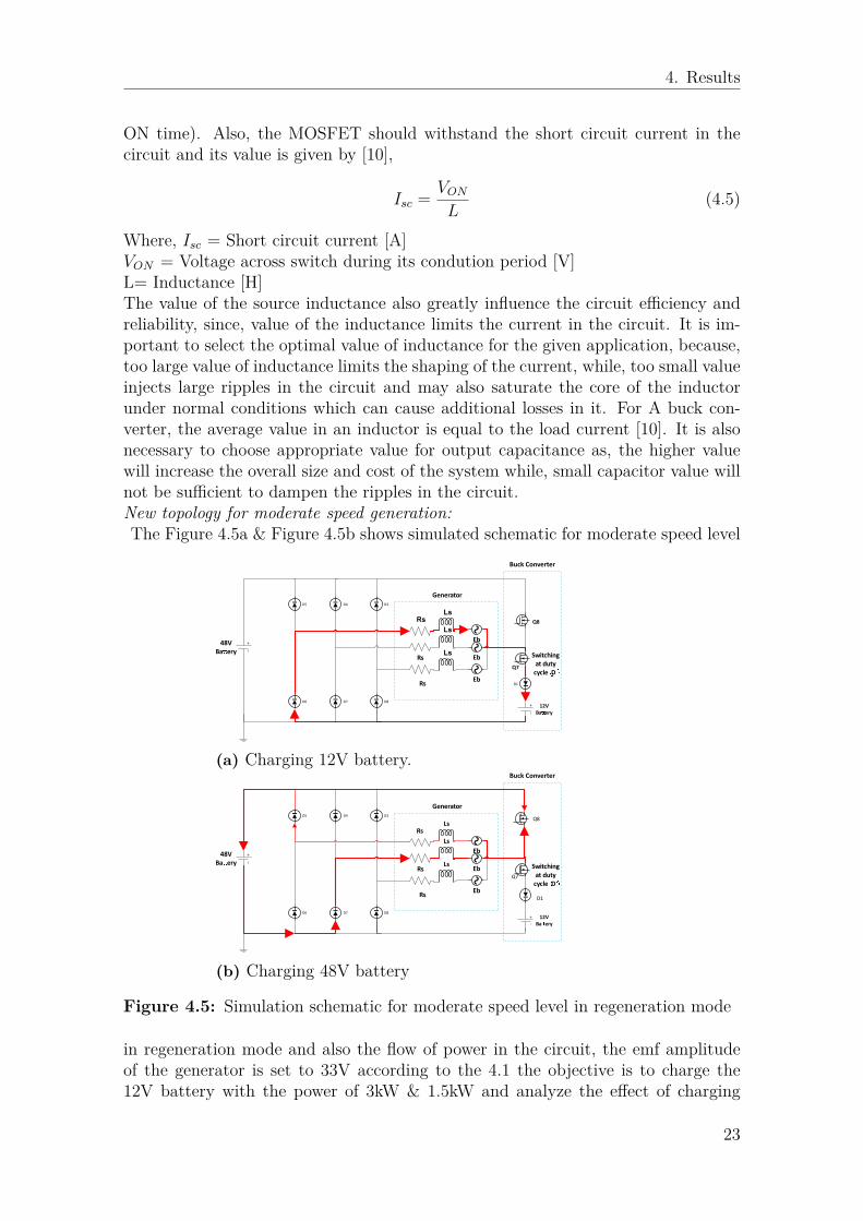
Where, Isc = Short circuit current [A]VON = Voltage across switch during its condution period [V]L= Inductance [H]The value of the source inductance also greatly influence the circuit efficiency andreliability, since, value of the inductance limits the current in the circuit. It is im-portant to select the optimal value of inductance for the given application, because,too large value of inductance limits the shaping of the current, while, too small valueinjects large ripples in the circuit and may also saturate the core of the inductorunder normal conditions which can cause additional losses in it. For A buck con-verter, the average value in an inductor is equal to the load current [10]. It is alsonecessary to choose appropriate value for output capacitance as, the higher valuewill increase the overall size and cost of the system while, small capacitor value willnot be sufficient to dampen the ripples in the circuit.New topology for moderate speed generation:The Figure 4.5a & Figure 4.5b shows simulated schematic for moderate speed level
Rs
Ls
Ls
Ls
Eb
Eb
EbD1
48V
Baery
12V
Baery
Rs
Rs
D3D4D5
D6 D7 D8
Generator
Switching
at duty
cycle DQ7
Buck Converter
Q8
(a) Charging 12V battery.
RsLs
Ls
Ls
Eb
Eb
EbD1
48V
Baery
12V
Baery
Rs
Rs
D3D4D5
D6 D7 D8
Generator
Switching
at duty
cycle DQ7
Buck Converter
Q8
(b) Charging 48V battery
Figure 4.5: Simulation schematic for moderate speed level in regeneration mode
in regeneration mode and also the flow of power in the circuit, the emf amplitudeof the generator is set to 33V according to the 4.1 the objective is to charge the12V battery with the power of 3kW & 1.5kW and analyze the effect of charging
23
4. Results
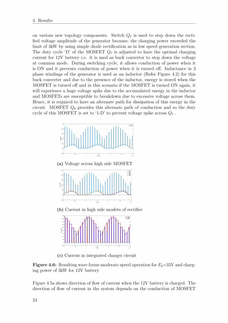
on various new topology components. Switch Q7 is used to step down the recti-fied voltage amplitude of the generator because; the charging power exceeded thelimit of 3kW by using simple diode rectification as in low speed generation section.The duty cycle ‘D’ of the MOSFET Q7 is adjusted to have the optimal chargingcurrent for 12V battery i.e. it is used as buck convertor to step down the voltageat common mode. During switching cycle, it allows conduction of power when itis ON and it prevents conduction of power when it is turned off. Inductance in 3phase windings of the generator is used as an inductor (Refer Figure 4.2) for thisbuck converter and due to the presence of the inductor, energy is stored when theMOSFET is turned off and in this scenario if the MOSFET is turned ON again, itwill experience a huge voltage spike due to the accumulated energy in the inductorand MOSFETs are susceptible to breakdown due to excessive voltage across them.Hence, it is required to have an alternate path for dissipation of this energy in thecircuit. MOSFET Q8 provides this alternate path of conduction and so the dutycycle of this MOSFET is set to ‘1-D’ to prevent voltage spike across Q7 .
0 0.5 1 1.5 2 2.5 3
time[s] 10-3
47.8
48
48.2
48.4
48.6
48.8
49
Voltage[V
]
Vbri
(a) Voltage across high side MOSFET
0 0.5 1 1.5 2 2.5 3
time[s] 10-3
-100
0
100
200
300
400
500
Curr
ent[A
]
I48
IM1
IM2
IM3
(b) Current in high side mosfets of rectifier
0 0.5 1 1.5 2 2.5 3
time[s] 10-3
-50
0
50
100
150
200
250
300
350
400
450
Curr
ent[A
]
IdM7
IsM8
(c) Current in integrated charger circuit
Figure 4.6: Resulting wave forms moderate speed operation for Eb=33V and charg-ing power of 3kW for 12V battery
Figure 4.5a shows direction of flow of current when the 12V battery is charged. Thedirection of flow of current in the system depends on the conduction of MOSFET
24
4. Results
Q7 & Q8. At instant, when MOSFET Q7 is conducting, the current will flow fromgenerator to 12V battery and complete the loop back to the generator through thediodes in lower leg of 3 phase conventional inverter Figure 4.5a. During conductionof MOSFET Q8 (Refer Figure 4.5b, the current flows from generator to 48V batterythrough the body diode of MOSFET Q8 because, the high side of the half bridgeis greater than 48V as shown by Vbri in Figure 4.6a. Also, current flows fromgenerator to 48V through the body diodes of M1, M2 and M3 in the upper leg of3 phase conventional inverter shown by currents IM1, IM2 and IM3 and chargingcurrent of 48V battery I48 in Figure 4.5b, Figure4.6b & Figure4.6c Hence, it canbe said that, 48V battery is charged most of the time during this level. Similarly,
0 0.5 1 1.5 2 2.5 3
time[s] 10-3
-1000
-500
0
500
Voltage[V
]
Vd1
0 0.5 1 1.5 2 2.5 3
time[s] 10-3
0
200
400
600
800
1000
Voltage[V
]
VM7
VM8
Figure 4.7: Voltage across MOSFET Q7 switches and diode D2 in half bridgechopper.
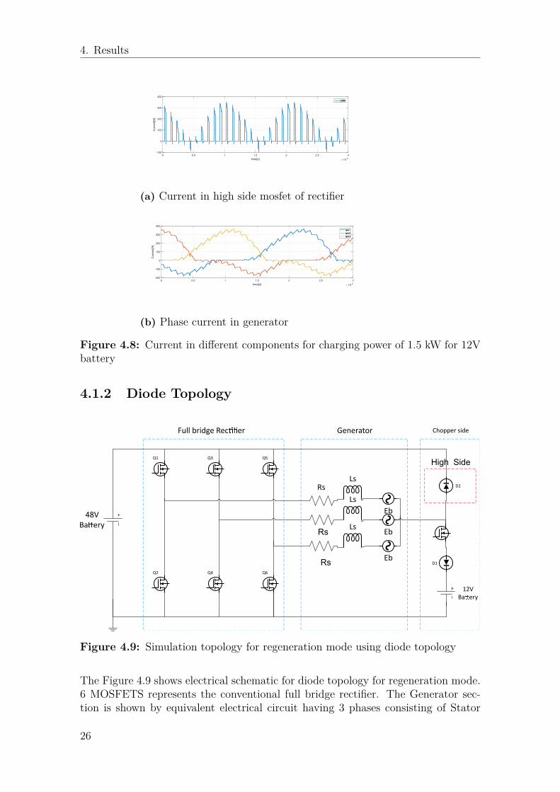
the simulation is performed for charging power of 1.5kW for 12V battery to seethe ripple in the system. It is observed that the voltage across switch M8 anddiode d1 has huge voltage spike as shown by voltages Vd1 and VM8 in Figure 4.7.This happened because, For 1.5kW, the duty cycle of Q7 is reduced than for 3kWwhich resulted in increased conduction time for switch Q8, and that cause a loopbetween generator MOSFETs in upper leg of 3 phase conventional inverter andthe switch Q8 causing increasing in the amount of current IM1, IM2, IM3, currentin upper leg of 3 phase conventional inverter. IL1, IL2, IL3, current in 3 phasewindings of generator and IM8 current in switch Q8, as shown in Figure 4.8a andFigure4.8b due to the fact that the loop is almost like a short circuit and hence, thisincrease in current cause high voltage spike across MOSFET Q8 and diode d1. Thisincrease in unwanted flow of current loop also causes higher losses in MOSFETsand in generator windings reducing the efficiency of the system. To avoid this, theswitching frequency can be decrease but, that will increase the ripple in the systemso, the only way is to add filter across MOSFET which will increase number ofcomponents in the system increasing cost and losses and also increase the losses inthe system decreasing further the overall efficiency. Hence, it is decided to replaceMOSFET Q8 with a diode, which will be discussed in next section.
25
4. Results
0 0.5 1 1.5 2 2.5 3
time[s] 10-3
-100
0
100
200
300
400
Curr
ent[A
]
IsM8
(a) Current in high side mosfet of rectifier
0 0.5 1 1.5 2 2.5 3
time[s] 10-3
-200
-100
0
100
200
300
400
Curr
ent[A
]
Iph1
Iph2
Iph3
(b) Phase current in generator
Figure 4.8: Current in different components for charging power of 1.5 kW for 12Vbattery
4.1.2 Diode Topology
Q1
Q2
Q3
Q4
Q5
Q6
RsLs
Ls
Ls
Eb
Eb
EbD1
D2
48V
Baery
Full bridge Recer Generator Chopper side
12V
Baery
High Side
Rs
Rs
Figure 4.9: Simulation topology for regeneration mode using diode topology
The Figure 4.9 shows electrical schematic for diode topology for regeneration mode.6 MOSFETS represents the conventional full bridge rectifier. The Generator sec-tion is shown by equivalent electrical circuit having 3 phases consisting of Stator
26
4. Results
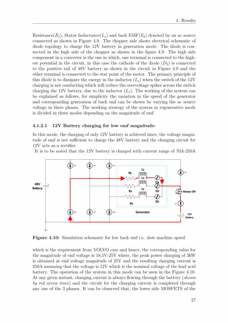
Resistance(Rs), Stator Inductance(Ls) and back EMF(Eb) denoted by an ac sourceconnected as shown in Figure 4.9. The chopper side shows electrical schematic ofdiode topology to charge the 12V battery in generation mode. The diode is con-nected in the high side of the chopper as shown in the figure 4.9. The high sidecomponent in a converter is the one in which, one terminal is connected to the high-est potential in the circuit, in this case the cathode of the diode (D2) is connectedto the positive rail of 48V battery as shown in the circuit in Figure 4.9 and theother terminal is connected to the star point of the motor. The primary principle ofthis diode is to dissipate the energy in the inductor (Ls) when the switch of the 12Vcharging is not conducting which will reduce the overvoltage spikes across the switchcharging the 12V battery, due to the inductor (Ls). The working of the system canbe explained as follows, for simplicity the variation in the speed of the generatorand corresponding generation of back emf can be shown by varying the ac sourcevoltage in three phases. The working strategy of the system in regenerative modeis divided in three modes depending on the magnitude of emf.
4.1.2.1 12V Battery charging for low emf magnitude:
In this mode, the charging of only 12V battery is achieved since, the voltage magni-tude of emf is not sufficient to charge the 48V battery and the charging circuit for12V acts as a rectifier.It is to be noted that the 12V battery is charged with current range of 70A-250A
RsLs
Ls
Ls
Eb
Eb
EbD1
D2
48V
Baery
12V
Baery
Rs
Rs
D3D4D5
D6 D7 D8 Generator
Always ON
Figure 4.10: Simulation schematic for low back emf i.e. slow machine speed
which is the requirement from VOLVO cars and hence, the corresponding value forthe magnitude of emf voltage is 18.5V-25V where, the peak power charging of 3kWis obtained at emf voltage magnitude of 25V and the resulting charging current is250A assuming that the voltage is 12V which is the nominal voltage of the lead acidbattery. The operation of the system in this mode can be seen in the Figure 4.10.At any given instant, charging current is always flowing through the battery (shownby red arrow trace) and the circuit for the charging current is completed throughany one of the 3 phases. It can be observed that, the lower side MOSFETS of the
27
4. Results
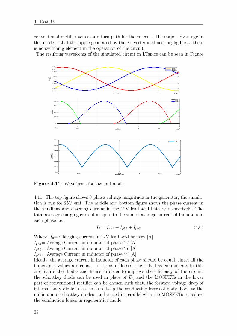
conventional rectifier acts as a return path for the current. The major advantage inthis mode is that the ripple generated by the converter is almost negligible as thereis no switching element in the operation of the circuit.The resulting waveforms of the simulated circuit in LTspice can be seen in Figure
0 0.5 1 1.5 2 2.5 3
time[s] 10-3
-50
0
50
100
150
200
250
300
350
Current[A]
Iph1
Iph2
Iph3
0 0.5 1 1.5 2 2.5 3
time[s] 10-3
50
100
150
200
250
300
350
Current[A]
I12
0 0.5 1 1.5 2 2.5 3
time[s] 10-3
-25
-20
-15
-10
-5
0
5
10
15
20
25
Voltage[V
]
Vph1
Vph2
Vph3
Figure 4.11: Waveforms for low emf mode
4.11. The top figure shows 3-phase voltage magnitude in the generator, the simula-tion is run for 25V emf. The middle and bottom figure shows the phase current inthe windings and charging current in the 12V lead acid battery respectively. Thetotal average charging current is equal to the sum of average current of Inductors ineach phase i.e.
I0 = Iph1 + Iph2 + Iph3 (4.6)
Where, I0= Charging current in 12V lead acid battery [A]Iph1= Average Current in inductor of phase ‘a’ [A]Iph2= Average Current in inductor of phase ‘b’ [A]Iph3= Average Current in inductor of phase ‘c’ [A]Ideally, the average current in inductor of each phase should be equal, since; all theimpedance values are equal. In terms of losses, the only loss components in thiscircuit are the diodes and hence in order to improve the efficiency of the circuit,the schottkey diode can be used in place of D1 and the MOSFETs in the lowerpart of conventional rectifier can be chosen such that, the forward voltage drop ofinternal body diode is less so as to keep the conducting losses of body diode to theminimum or schottkey diodes can be used in parallel with the MOSFETs to reducethe conduction losses in regenerative mode.
28
4. Results
4.1.2.2 Charging of 12V & 48V battery in complementary fashion:
RsLs
Ls
Ls
Eb
Eb
EbD1
D2
48V
Baery
12V
Baery
Rs
Rs
D3D4D5
D6 D7 D8
Generator
Switching
at duty
cycle DM1
Buck Converter
Figure 4.12: Working of simulation model for charging 48V battery & 12V batteryin complementary fashion
This mode is quite interesting because, it is possible to charge both the batteries incomplementary fashion. When the voltage magnitude is above 25V, it is required tostep down the common mode voltage to the desired value such that the 12V batterycan be charged with constant power of 3kW and this buck operation in this case isachieved by the single MOSFET (Q7) on the converter side in Figure 4.12 & Figure4.4 . The required duty cycle is calculated depending upon the value of commonmode voltage and equation 4.3. The 48V battery is charged when the MOSFET Q7is not conducting and instead diodeD2 starts conducting. In this mode, it is possibleto charge the 48V battery by the power of up to 2kW (Refer Figure 4.13c). Theflow of power is as shown in Figure 4.12 with red path shows charging of 12V leadacid battery and green path shows charging of 48V battery. Since, the MOSFETQ7 is switching in this mode to step down the voltage, there is a ripple generation inthe system but it is within the tolerable limit of current and output voltage ripple.Comparing the Figure 4.13a & Figure 4.13b with Figure 4.8b & Figure 4.8a suggestthat, the diode topology has less leakage of current in the conventional rectifierthan the MOSFET topology and hence, there are no voltage spikes observed acrossany component for 33V generator amplitude and 1.5kW charging for 12V battery.Which resulted no requirement of additional components to reduce voltage spikesin diode topology, Therefore, diode topology is adapted for further circuit topology.
29
4. Results
0 0.5 1 1.5 2 2.5 3
time[s] 10-3
-100
0
100
200
300
400
Cu
rre
nt[
A]
Iph1
Iph2
Iph3
(a) Phase Current
0 0.5 1 1.5 2 2.5 3
time[s] 10-3
0
20
40
60
80
100
Cu
rre
nt[
A]
IdM1
IdM2
IdM3
(b) Current through upper leg MOSFET of conventionalrectifier
0 0.5 1 1.5 2 2.5 3
time[s] 10-3
48
48.2
48.4
48.6
48.8
49
49.2
49.4
49.6
49.8
50
Vo
ltag
e[V
]
Vbri
(c) Voltage across high side diode
Figure 4.13: Waveforms for diode topology in moderate speed operation in re-generation mode for charging power of 1.5kW and generator voltage amplitude of33V
30
4. Results
4.1.2.3 Charging of 48V battery at higher emf magnitude:
Rs
Ls
Ls
Ls
Eb
Eb
EbD1
D2
48V
Baery
12V
Baery
Rs
Rs
D3D4D5
D6 D7 D8
Full Bridge Recer
Always
OFF
Generator
Figure 4.14: Simulation schematic for charging 48V battery
In this mode, the charging of 48V can only be achieved because, if the MOSFET(Q7) is switched to charge the 12V battery, the voltage across 48V battery goes upto 50V, which can cause current of very high magnitude since, there is no elementin the circuit which can limit the current flowing in 48V battery and eventually thiswill damage the battery and reduce its life. This is the conventional rectificationmethod charging of 48V battery. As shown in figure4.14 , The MOSFETS in the3-phase inverter acts as a conventional rectifier and hence they are shown by theinternal body diode.The Figure 4.15a shows waveforms obtained from LTspice when charging 48V bat-tery by conventional rectification method. The first figure shows phase current Iph1,Iph2 & Iph3 in the generator and charging current of 48V battery. The shape ofthe current waveform is a typical current waveform of a conventional rectificationprocess. The second figure of Figure 4.15a shows power in the system, P3ph[kW] isthe total average 3 phase power of the generator, in this case, the input power ofthe rectifier while, P48[kW] is the input for charging power of 48V battery. The P12[kW], charging power of 12V is zero since; there is no charging of 12V in this case.The third figure is the sinusoidal voltage in each phase of the generator Vph1, Vph2& Vph3 respectively. The ripple in the system is almost negligible as there are noswitching devices in the operation of the system.
31
4. Results
0 0.5 1 1.5 2 2.5 3
time[s] 10-3
-500
0
500C
urr
en
t[A
]IL1
IL2
IL3
I48
0 0.5 1 1.5 2 2.5 3
time[s] 10-3
-1
0
1
2
3
Po
wer[
kW
]
104
P48
P3ph
P12
(a) Charging current and power in 48V battery
0 0.5 1 1.5 2 2.5 3
time[s] 10-3
-40
-30
-20
-10
0
10
20
30
40
Vo
ltag
e[V
]
Vph1
Vph2
Vph3
(b) Phase voltage in electrical machine
Figure 4.15: Waveforms of charging 48V battery by conventional full bridge dioderectification
32
4. Results
4.1.2.4 Summary of Regeneration Mode:
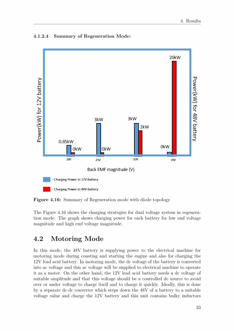
Figure 4.16: Summary of Regeneration mode with diode topology
The Figure 4.16 shows the charging strategies for dual voltage system in regenera-tion mode. The graph shows charging power for each battery for low emf voltagemagnitude and high emf voltage magnitude.
4.2 Motoring ModeIn this mode, the 48V battery is supplying power to the electrical machine formotoring mode during coasting and starting the engine and also for charging the12V lead acid battery. In motoring mode, the dc voltage of the battery is convertedinto ac voltage and this ac voltage will be supplied to electrical machine to operateit as a motor. On the other hand, the 12V lead acid battery needs a dc voltage ofsuitable amplitude and that this voltage should be a controlled dc source to avoidover or under voltage to charge itself and to charge it quickly. Ideally, this is doneby a separate dc-dc converter which steps down the 48V of a battery to a suitablevoltage value and charge the 12V battery and this unit contains bulky inductors
33
4. Results
and capacitors which make the unit costly, bulky and heavy. If we consider motoras source of energy to charge the battery, then it will require a rectifier to convertac voltage of the motor to dc voltage and a chopper to control the voltage. So, thesystem may be even bulkier, costlier and heavier.Common mode voltage of the inverter can be used as a source to charge the 12Vbattery since, it is a positive voltage due to the fact that, it is the voltage measuredbetween star point of the machine and the ground of the system which makes thepotential of this source always above zero amplitude. Hence, only a chopper will berequired in this case to get the voltage of required amplitude to charge the batterywhich can make the system less bulky and cost effective.The Figure 4.17 shows common mode voltage charging topology in motoring mode.
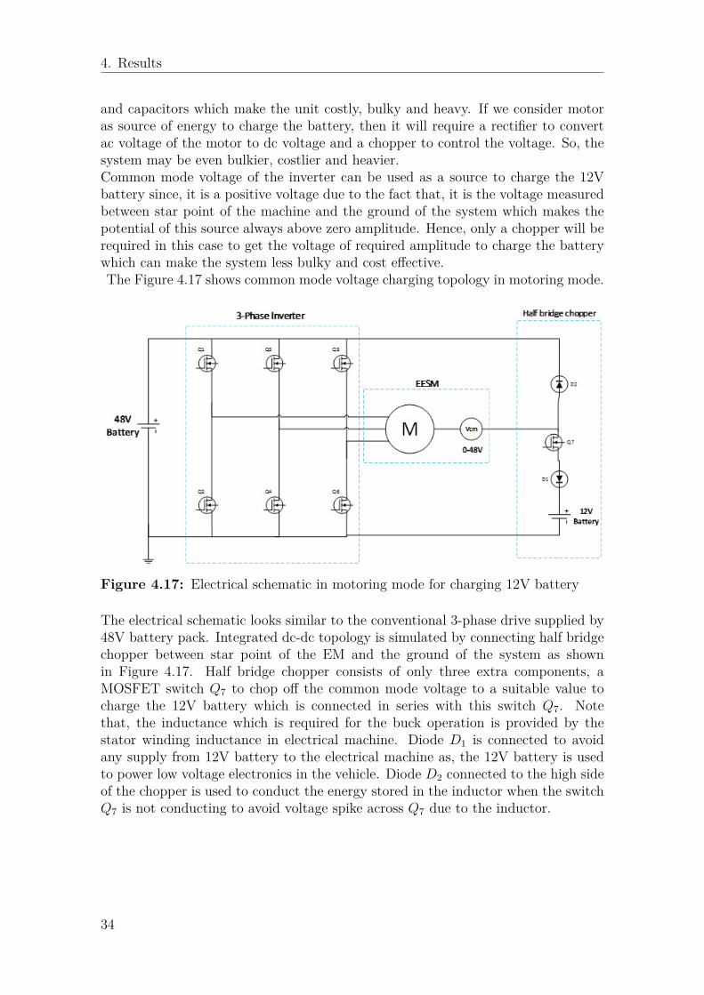
Figure 4.17: Electrical schematic in motoring mode for charging 12V battery
The electrical schematic looks similar to the conventional 3-phase drive supplied by48V battery pack. Integrated dc-dc topology is simulated by connecting half bridgechopper between star point of the EM and the ground of the system as shownin Figure 4.17. Half bridge chopper consists of only three extra components, aMOSFET switch Q7 to chop off the common mode voltage to a suitable value tocharge the 12V battery which is connected in series with this switch Q7. Notethat, the inductance which is required for the buck operation is provided by thestator winding inductance in electrical machine. Diode D1 is connected to avoidany supply from 12V battery to the electrical machine as, the 12V battery is usedto power low voltage electronics in the vehicle. Diode D2 connected to the high sideof the chopper is used to conduct the energy stored in the inductor when the switchQ7 is not conducting to avoid voltage spike across Q7 due to the inductor.
34
4. Results
4.2.1 Circuit Operation
Q1
Q2
Q3
Q4
Q5
Q6
Q7
D1
D2
48V
Baery
3-Phase Inverter
12V
Baery
Half bridge chopper
EESM
Rs
Ls
Ls
Ls
Eb
Eb
Eb
Rs
Rs
(a) Circuit operation when 12V battery is charging duringmotoring mode
Q1
Q2
Q3
Q4
Q5
Q6
Q7
D1
D2
48V
Baery
3-Phase Inverter
12V
Baery
Half bridge chopper
EESM
Rs
Ls
Ls
Ls
Eb
Eb
Eb
Rs
Rs
(b) Circuit operation when 12V battery is not charging.
Figure 4.18: Working strategy in Motoring mode
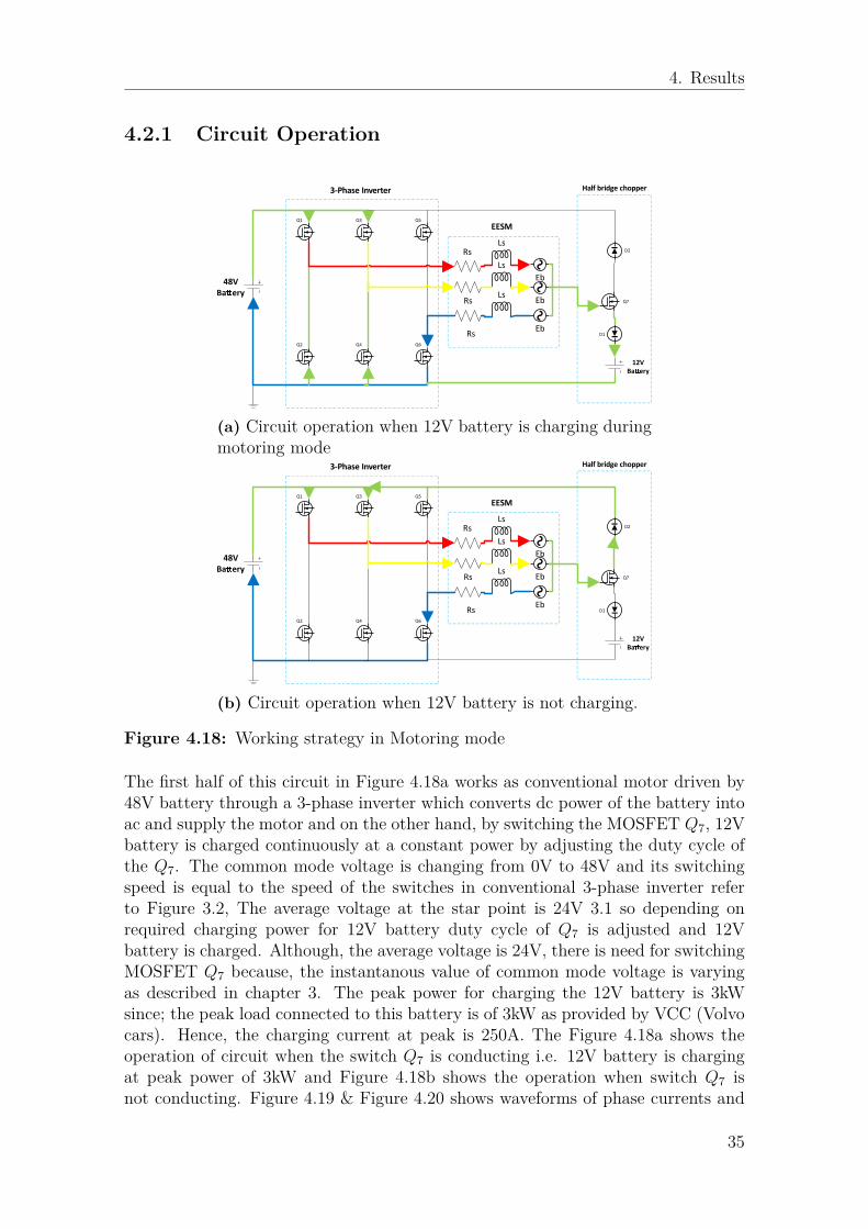
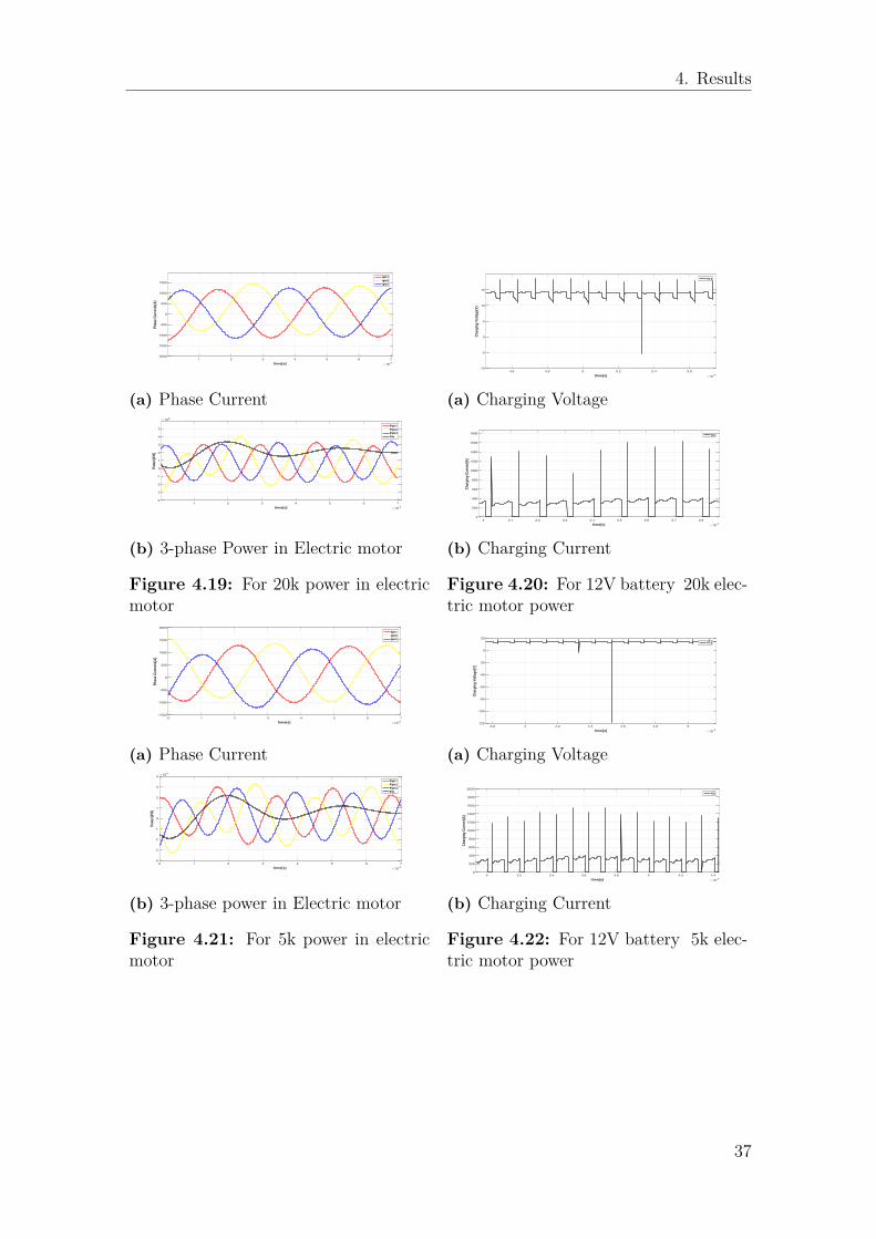
The first half of this circuit in Figure 4.18a works as conventional motor driven by48V battery through a 3-phase inverter which converts dc power of the battery intoac and supply the motor and on the other hand, by switching the MOSFET Q7, 12Vbattery is charged continuously at a constant power by adjusting the duty cycle ofthe Q7. The common mode voltage is changing from 0V to 48V and its switchingspeed is equal to the speed of the switches in conventional 3-phase inverter referto Figure 3.2, The average voltage at the star point is 24V 3.1 so depending onrequired charging power for 12V battery duty cycle of Q7 is adjusted and 12Vbattery is charged. Although, the average voltage is 24V, there is need for switchingMOSFET Q7 because, the instantanous value of common mode voltage is varyingas described in chapter 3. The peak power for charging the 12V battery is 3kWsince; the peak load connected to this battery is of 3kW as provided by VCC (Volvocars). Hence, the charging current at peak is 250A. The Figure 4.18a shows theoperation of circuit when the switch Q7 is conducting i.e. 12V battery is chargingat peak power of 3kW and Figure 4.18b shows the operation when switch Q7 isnot conducting. Figure 4.19 & Figure 4.20 shows waveforms of phase currents and
35
4. Results
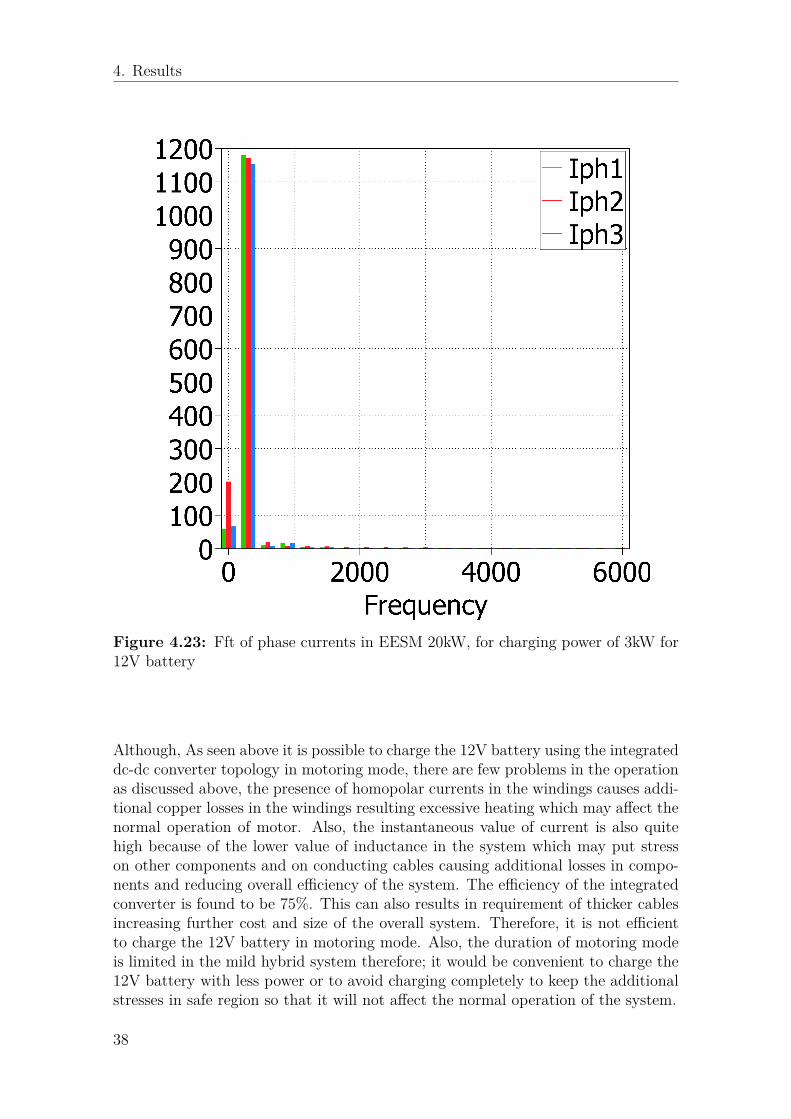
total power in electrical machine and also the charging voltage & current for peakcharging power of 3kW. The half bridge chopper acts as a buck convert steppingdown the common mode voltage and hence for the buck converter, its load current isequal to the current flowing through its inductor. In this case, the load current is thecharging current of the 12V battery and this current is flowing through the statorinductor of the electrical machine, since; this inductor is used as an inductance forthe buck converter in the topology. That is why, the waveforms of the phase currentsand phase powers of electrical not symmetrical about x-axis in the Figure 4.19 andthis can be also seen in Figure 4.23 in which, its shows fft (Fast Fourior transform) ofphase currents in EM (Electrical machine). There is presence of component at 0 Hzin the phase currents which proves that there is a homopolar component of currentpresent in the stator windings of the EM due to the zero-sequence charging of 12Vbattery. Figure 4.22 also shows that, there is high voltage and current spikes in thecharging power of 12V battery and the spike is higher at 5kW load on EM. It wasobserved that when the switch Q7 is not conducting refer Figure 4.18b, the energystored in the inductor is conducting through the diode d2 which is a low resistancepath which results in increasing the amplitude of current which further increasesthe energy in inductor for a brief moment and again when the switch Q7 startsconducting that energy is dissipated on the switch and because of the controlledduty cycle of switch Q7, there is voltage and current spike observed during thecharging of the 12V battery.The presence of homopolar current in the motor causesvery high copper losses in the windings which may result in excessive heating of themotor. A very simple solution for this problem would be to connect a capacitoracross battery which will absorb these spikes and keep the conditions under safelevel.Figure 4.24a & Figure 4.24b shows that the spikes in charging voltage and currentcan be significantly reduced by adding a capacitor across battery. 3.2. Currentripple is 30.8% which is just on margin as far as tolerable value of ripple goes forthe switching devices for vehicle application and the voltage ripple is 2% which iswithin acceptable range. [6]
36
4. Results
1 2 3 4 5 6 7
time[s] 10-3
-2000
-1500
-1000
-500
0
500
1000
1500
Ph
ase
Cu
rren
ts[A
]
Iph1
Iph2
Iph3
(a) Phase Current
1 2 3 4 5 6 7
time[s] 10-3
-4
-3
-2
-1
0
1
2
3
4
5
Po
wer
[kW
]
104
Pph1
Pph2
Pph3
Pm
(b) 3-phase Power in Electric motor
Figure 4.19: For 20k power in electricmotor
4.6 4.8 5 5.2 5.4 5.6
time[s] 10-3
-10
-5
0
5
10
15
Ch
arg
ing
Vo
ltag
e[V
]
V12
(a) Charging Voltage
3 3.1 3.2 3.3 3.4 3.5 3.6 3.7 3.8
time[s] 10-3
0
200
400
600
800
1000
1200
1400
1600
1800
Ch
arg
ing
Cu
rren
t[A
]
I12
(b) Charging Current
Figure 4.20: For 12V battery 20k elec-tric motor power
0 1 2 3 4 5 6 7
time[s] 10-3
-1500
-1000
-500
0
500
1000
1500
2000
Ph
ase
Cu
rren
ts[A
]
Iph1
Iph2
Iph3
(a) Phase Current
0 1 2 3 4 5 6 7
time[s] 10-3
-4
-3
-2
-1
0
1
2
3
4
Po
wer
[kW
]
104
Pph1
Pph2
Pph3
Pm
(b) 3-phase power in Electric motor
Figure 4.21: For 5k power in electricmotor
3.8 4 4.2 4.4 4.6 4.8 5
time[s] 10-3
-120
-100
-80
-60
-40
-20
0
20
Ch
arg
ing
Vo
ltag
e[V
]
V12
(a) Charging Voltage
3 3.2 3.4 3.6 3.8 4 4.2 4.4
time[s] 10-3
0
200
400
600
800
1000
1200
1400
1600
1800
2000
Ch
arg
ing
Cu
rren
t[A
]
I12
(b) Charging Current
Figure 4.22: For 12V battery 5k elec-tric motor power
37
4. Results
Figure 4.23: Fft of phase currents in EESM 20kW, for charging power of 3kW for12V battery
Although, As seen above it is possible to charge the 12V battery using the integrateddc-dc converter topology in motoring mode, there are few problems in the operationas discussed above, the presence of homopolar currents in the windings causes addi-tional copper losses in the windings resulting excessive heating which may affect thenormal operation of motor. Also, the instantaneous value of current is also quitehigh because of the lower value of inductance in the system which may put stresson other components and on conducting cables causing additional losses in compo-nents and reducing overall efficiency of the system. The efficiency of the integratedconverter is found to be 75%. This can also results in requirement of thicker cablesincreasing further cost and size of the overall system. Therefore, it is not efficientto charge the 12V battery in motoring mode. Also, the duration of motoring modeis limited in the mild hybrid system therefore; it would be convenient to charge the12V battery with less power or to avoid charging completely to keep the additionalstresses in safe region so that it will not affect the normal operation of the system.
38
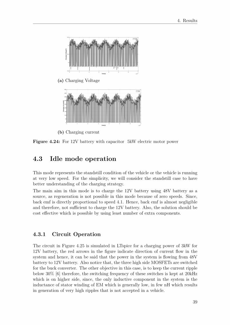
4. Results
0 1 2 3 4 5 6 7
time[s] 10-3
12.5
13
13.5
14
14.5
Ch
arg
ing
Vo
ltag
e[V
]
V12
(a) Charging Voltage
0 1 2 3 4 5 6 7
time[s] 10-3
0
50
100
150
200
250
300
350
400
450
Ch
arg
ing
Cu
rren
t[A
]
I12
(b) Charging current
Figure 4.24: For 12V battery with capacitor 5kW electric motor power
4.3 Idle mode operation
This mode represents the standstill condition of the vehicle or the vehicle is runningat very low speed. For the simplicity, we will consider the standstill case to havebetter understanding of the charging strategy.The main aim in this mode is to charge the 12V battery using 48V battery as asource, as regeneration is not possible in this mode because of zero speeds. Since,back emf is directly proportional to speed 4.1. Hence, back emf is almost negligibleand therefore, not sufficient to charge the 12V battery. Also, the solution should becost effective which is possible by using least number of extra components.
4.3.1 Circuit Operation
The circuit in Figure 4.25 is simulated in LTspice for a charging power of 3kW for12V battery, the red arrows in the figure indicate direction of current flow in thesystem and hence, it can be said that the power in the system is flowing from 48Vbattery to 12V battery. Also notice that, the three high side MOSFETs are switchedfor the buck converter. The other objective in this case, is to keep the current ripplebelow 30% [6] therefore, the switching frequency of these switches is kept at 20kHzwhich is on higher side, since, the only inductive component in the system is theinductance of stator winding of EM which is generally low, in few nH which resultsin generation of very high ripples that is not accepted in a vehicle.
39
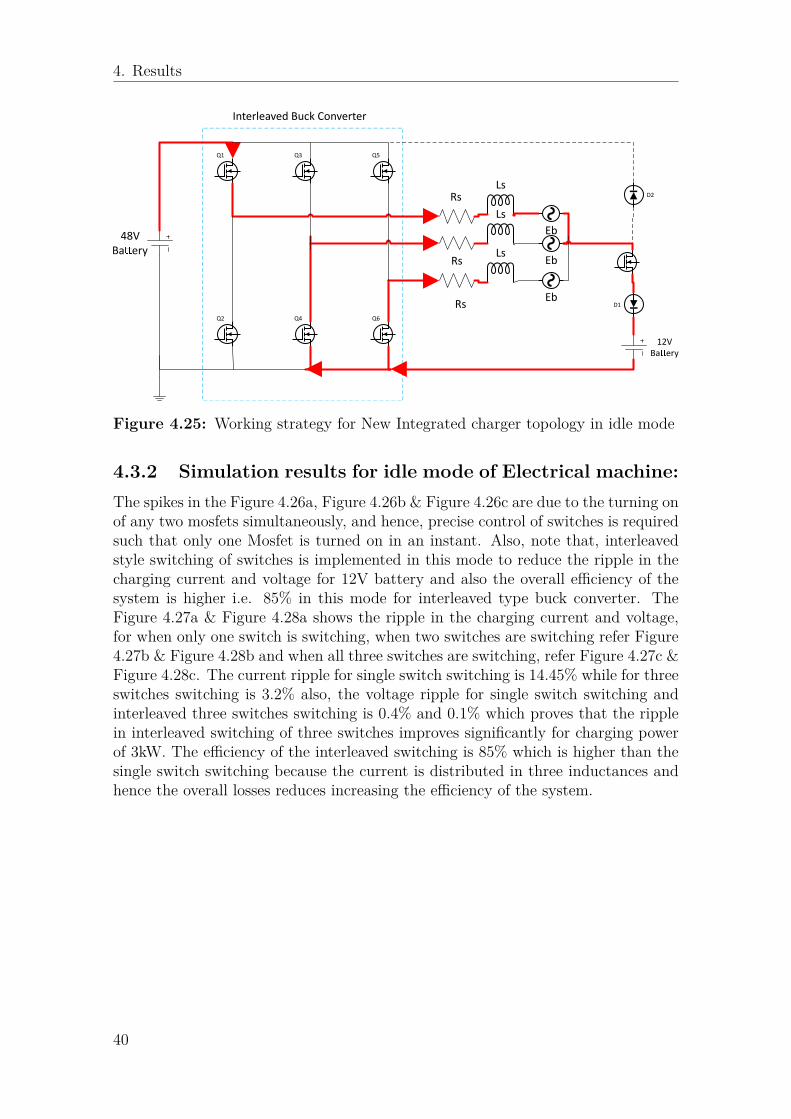
4. Results
Q1
Q2
Q3
Q4
Q5
Q6
RsLs
Ls
Ls
Eb
Eb
EbD1
D2
48V
Baery
Interleaved Buck Converter
12V
Baery
Rs
Rs
Figure 4.25: Working strategy for New Integrated charger topology in idle mode
4.3.2 Simulation results for idle mode of Electrical machine:The spikes in the Figure 4.26a, Figure 4.26b & Figure 4.26c are due to the turning onof any two mosfets simultaneously, and hence, precise control of switches is requiredsuch that only one Mosfet is turned on in an instant. Also, note that, interleavedstyle switching of switches is implemented in this mode to reduce the ripple in thecharging current and voltage for 12V battery and also the overall efficiency of thesystem is higher i.e. 85% in this mode for interleaved type buck converter. TheFigure 4.27a & Figure 4.28a shows the ripple in the charging current and voltage,for when only one switch is switching, when two switches are switching refer Figure4.27b & Figure 4.28b and when all three switches are switching, refer Figure 4.27c &Figure 4.28c. The current ripple for single switch switching is 14.45% while for threeswitches switching is 3.2% also, the voltage ripple for single switch switching andinterleaved three switches switching is 0.4% and 0.1% which proves that the ripplein interleaved switching of three switches improves significantly for charging powerof 3kW. The efficiency of the interleaved switching is 85% which is higher than thesingle switch switching because the current is distributed in three inductances andhence the overall losses reduces increasing the efficiency of the system.
40
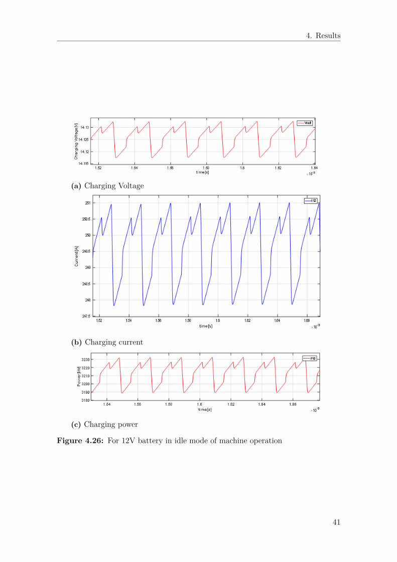
4. Results
(a) Charging Voltage
(b) Charging current
(c) Charging power
Figure 4.26: For 12V battery in idle mode of machine operation
41
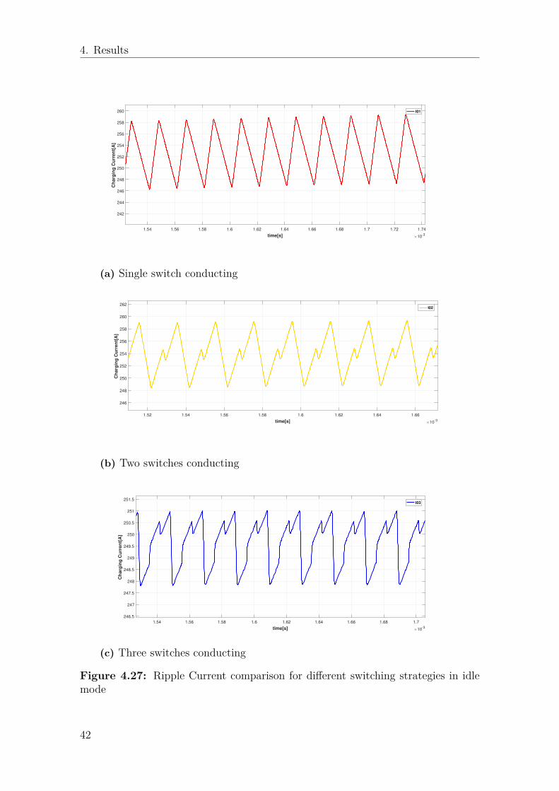
4. Results
1.54 1.56 1.58 1.6 1.62 1.64 1.66 1.68 1.7 1.72 1.74
time[s] 10-3
242
244
246
248
250
252
254
256
258
260C
ha
rgin
g C
urr
en
t[A
]I01
(a) Single switch conducting
1.52 1.54 1.56 1.58 1.6 1.62 1.64 1.66
time[s] 10-3
246
248
250
252
254
256
258
260
262
Ch
arg
ing
Cu
rre
nt[
A]
I02
(b) Two switches conducting
1.54 1.56 1.58 1.6 1.62 1.64 1.66 1.68 1.7
time[s] 10-3
246.5
247
247.5
248
248.5
249
249.5
250
250.5
251
251.5
Ch
arg
ing
Cu
rre
nt[
A]
I03
(c) Three switches conducting
Figure 4.27: Ripple Current comparison for different switching strategies in idlemode
42
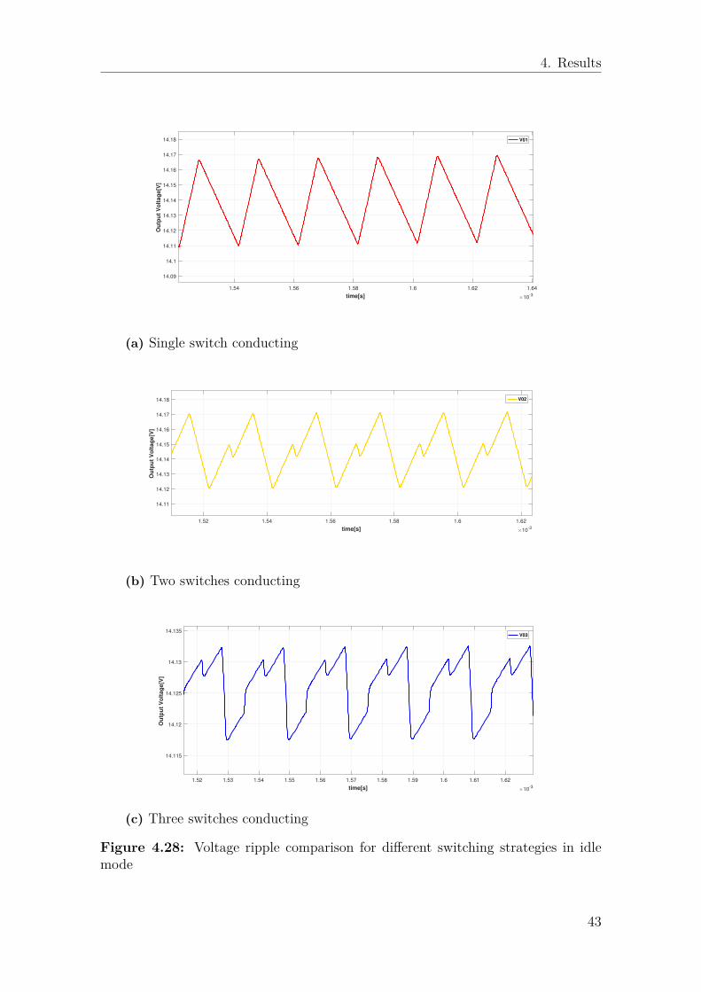
4. Results
1.54 1.56 1.58 1.6 1.62 1.64
time[s] 10-3
14.09
14.1
14.11
14.12
14.13
14.14
14.15
14.16
14.17
14.18
Ou
tpu
t V
olt
ag
e[V
]
V01
(a) Single switch conducting
1.52 1.54 1.56 1.58 1.6 1.62
time[s] 10-3
14.11
14.12
14.13
14.14
14.15
14.16
14.17
14.18
Ou
tpu
t V
olt
ag
e[V
]
V02
(b) Two switches conducting
1.52 1.53 1.54 1.55 1.56 1.57 1.58 1.59 1.6 1.61 1.62
time[s] 10-3
14.115
14.12
14.125
14.13
14.135
Ou
tpu
t V
olt
ag
e[V
]
V03
(c) Three switches conducting
Figure 4.28: Voltage ripple comparison for different switching strategies in idlemode
43

4. Results
44
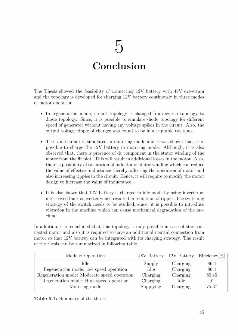
5Conclusion
The Thesis showed the feasibility of connecting 12V battery with 48V drivetrainand the topology is developed for charging 12V battery continously in three modesof motor operation.
• In regeneration mode, circuit topology is changed from switch topology todiode topology. Since, it is possible to simulate diode topology for differentspeed of generator without having any voltage spikes in the circuit. Also, theoutput voltage ripple of charger was found to be in acceptable tolerance.
• The same circuit is simulated in motoring mode and it was shown that, it ispossible to charge the 12V battery in motoring mode. Although, it is alsoobserved that, there is presence of dc component in the stator winding of themotor from the fft plot. This will result in additional losses in the motor. Also,there is posiibility of saturation of inductor of stator winding which can reducethe value of effective inductance thereby, affecting the operation of motor andalso increasing ripples in the circuit. Hence, it will require to modify the motordesign to increase the value of inductance.
• It is also shown that 12V battery is charged in idle mode by using inverter asinterleaved buck converter which resulted in reduction of ripple. The switchingstrategy of the switch needs to be studied, since, it is possible to introducevibration in the machine which can cause mechanical degradation of the ma-chine.
In addition, it is concluded that this topology is only possible in case of star con-nected motor and also it is required to have an additional neutral connection frommotor so that 12V battrey can be integrated with its charging strategy. The resultof the thesis can be summarized in following table,
Mode of Operation 48V Battery 12V Battery Efficiency[%]Idle Supply Charging 86.4
Regeneration mode: low speed operation Idle Charging 86.4Regeneration mode: Moderate speed operation Charging Charging 85.45
Regeneration mode: High speed operation Charging Idle 91Motoring mode Supplying Charging 75.37
Table 5.1: Summary of the thesis
45

5. Conclusion
5.1 Future WorkThis thesis was mainly focused on developing simulation model to establish a charg-ing strategy for Integrated charger topology of 12V battery with 48V drivetrain forDual voltage Mild hybrid system. The simulation results were obtained for steadystate, generic model of Battery and 3-phase motor. For increasing power demand,generally a 5-phase ISG is considered and hence, it is necessary to check the feasi-bility of this model for a 5-phase machine. Also, The analysis should be made basedon a dynamic model of batteries in which, the effect of change in different voltage ofboth the batteries on the charging strategy can be studied. It is also important tostudy the dynamic model of ISG which can make it possible to study the followingeffect on motor;
• In the motoring mode, the actual torque that is available for motor whenintegrated charging of 12V is initiated when, there is a limit on maximumpower limit on motor.
• The change in stator inductance due to the presence of homo-polar current inthe stator winding of ISG when integrated charging is initiated in motoringmode.
• The additional losses and heating of ISG for different load condition, whichwill give idea on an additional cooling, if required for the ISG due to theintegrated charging.
This study will help to predict the total cost and size required to for the proposedintegrated strategy which then can be compared with the existing dc/dc solution.Further, The complex controller logic needs to be designed for this strategy whichwill make an easy transition between various charging strategy for 12V battery toattain continuous charging as explained in this thesis work for different modes ofmotor operation.
46
Bibliography
[1] Mario A. Silva, Hugo Neves De Melo, Joao P Trovao, Paulo G. Pereirinha,Humberto M. Jorge (2013) Hybrid topologies comparison for Electric vehicleswith Multiple energy storage systems, EVS27 International Battery, Hybrid andFuel cell Electric vehicle Symposium
[2] Tiecheng Wang, Haifang Yu and Chunbo Zhu, (2008) Hybrid Energy Sourcesfor Hybrid Electric Vehicle Propulsion, IEEE Vehicle Power and PropulsionConference (VPPC), September 3-5, 2008, Harbin, China
[3] Jacek Junak (2015) Development of vehicle drivetrain and its components solu-tions for CO2 reduction, 2015 International Conference on Sustainable MobilityApplications, Renewables and Technology (SMART)
[4] Thomas J. Dougherty (2002) Dual voltage alternator using center-tap regulationUS 6392348 B1, GRANT publications
[5] Murat Senol, Rik W. De Doncker (2015) Drivetrain Integrated Dc-Dc Converterutilizing the Zero Sequence Current of the Starter-Generator in 48V NetworkVehicles, Institute for Power Electronics and Electrical Drives (ISEA), 978-1-4763-7239-8/15/$31.00 ’ 2015 IEEE
[6] Jamie Carol Byrum (2000) A Master thesis on Comparative Evaluation of Dual-Voltage Automotive Alternators, at the Massachusetts Institute of Technology
[7] Jianbao Liu, Xinxin Qin, and Zhonglin Yang (2011) Analysis of Zero-SequenceCirculating Current in Parallel PWM Inverter System with Difference of Car-rier Wave Phases, Informatics in Control, Automation and Robotics, LNEE132, pp. 453–463.
[8] S . Chen, T. A. Lipo, and D. Fitzgerald (1996) Source of Induction MotorBearing Currents Caused by PWM Inverters, 0885-8969/96/$05.00 0 1995 IEEE
[9] ABB (2011) Bearing currents in modern AC drive systems, technical guide 5https://library.e.abb.com/public/8c253c2417ed0238c125788f003cca8e/ABB_Technical_guide_No5_RevC.pdf
[10] Sanjaya Maniktala (2006), Switching Power Supplies A-Z,Elsevier publications
[11] N. Mohan, et al. (2003) Power Electronics: Converters, Applications, and De-sign, third edition, USA: John Wiley and Sons, Inc
47

Bibliography
[12] (2016) 48-Volt Electrical Systems –A Key Technology Paving to the Road toElectric Mobilityhttps://www.zvei.org/fileadmin/userupload/PresseundMedien/Publikationen/2016/april/48−V oltElectricalSystems−AKeyT echnologyPavingtheRoadtoElectricMobility/48−V olt− Electrical − Systems− Electric−Mobility − engl − 2016.pdf
48