Embed Size (px)
Citation preview

John E. Foster, Aimee Hubble, and Sarah Nowak-GuckerThe University of Michigan, Ann Arbor, Michigan
Chris Davis, Peter Peterson, Eric Viges, and Dave ChenElectroDynamic Applications, Inc., Ann Arbor, Michigan
Simulated Beam Extraction PerformanceCharacterization of a 50-cm IonThruster Discharge
NASA/CR—2013-217828
June 2013
AIAA–2012–3795
https://ntrs.nasa.gov/search.jsp?R=20140000334 2018-07-22T14:39:29+00:00Z

NASA STI Program . . . in Profi le
Since its founding, NASA has been dedicated to the advancement of aeronautics and space science. The NASA Scientifi c and Technical Information (STI) program plays a key part in helping NASA maintain this important role.
The NASA STI Program operates under the auspices of the Agency Chief Information Offi cer. It collects, organizes, provides for archiving, and disseminates NASA’s STI. The NASA STI program provides access to the NASA Aeronautics and Space Database and its public interface, the NASA Technical Reports Server, thus providing one of the largest collections of aeronautical and space science STI in the world. Results are published in both non-NASA channels and by NASA in the NASA STI Report Series, which includes the following report types: • TECHNICAL PUBLICATION. Reports of
completed research or a major signifi cant phase of research that present the results of NASA programs and include extensive data or theoretical analysis. Includes compilations of signifi cant scientifi c and technical data and information deemed to be of continuing reference value. NASA counterpart of peer-reviewed formal professional papers but has less stringent limitations on manuscript length and extent of graphic presentations.
• TECHNICAL MEMORANDUM. Scientifi c
and technical fi ndings that are preliminary or of specialized interest, e.g., quick release reports, working papers, and bibliographies that contain minimal annotation. Does not contain extensive analysis.
• CONTRACTOR REPORT. Scientifi c and
technical fi ndings by NASA-sponsored contractors and grantees.
• CONFERENCE PUBLICATION. Collected papers from scientifi c and technical conferences, symposia, seminars, or other meetings sponsored or cosponsored by NASA.
• SPECIAL PUBLICATION. Scientifi c,
technical, or historical information from NASA programs, projects, and missions, often concerned with subjects having substantial public interest.
• TECHNICAL TRANSLATION. English-
language translations of foreign scientifi c and technical material pertinent to NASA’s mission.
Specialized services also include creating custom thesauri, building customized databases, organizing and publishing research results.
For more information about the NASA STI program, see the following:
• Access the NASA STI program home page at http://www.sti.nasa.gov
• E-mail your question to [email protected] • Fax your question to the NASA STI
Information Desk at 443–757–5803 • Phone the NASA STI Information Desk at 443–757–5802 • Write to:
STI Information Desk NASA Center for AeroSpace Information 7115 Standard Drive Hanover, MD 21076–1320

John E. Foster, Aimee Hubble, and Sarah Nowak-GuckerThe University of Michigan, Ann Arbor, Michigan
Chris Davis, Peter Peterson, Eric Viges, and Dave ChenElectroDynamic Applications, Inc., Ann Arbor, Michigan
Simulated Beam Extraction PerformanceCharacterization of a 50-cm IonThruster Discharge
NASA/CR—2013-217828
June 2013
AIAA–2012–3795
National Aeronautics andSpace Administration
Glenn Research CenterCleveland, Ohio 44135
Prepared under Contracts NNX10CF59P and NNX11CC56C
Prepared for the48th Joint Propulsion Conference and Exhibitcosponsored by the AIAA, ASME, SAE, and ASEEAtlanta, Georgia, July 30–August 1, 2012

Acknowledgments
This work is supported by NASA under the STTR program, contract numbers: NNX10CF59P and NNX11CC56C.
Available from
NASA Center for Aerospace Information7115 Standard DriveHanover, MD 21076–1320
National Technical Information Service5301 Shawnee Road
Alexandria, VA 22312
Available electronically at http://www.sti.nasa.gov
Level of Review: This material has been technically reviewed by expert reviewer(s).
This report contains preliminary fi ndings, subject to revision as analysis proceeds.

Simulated Beam Extraction Performance Characterization of a 50-cm Ion Thruster Discharge
A 50 cm ion thruster is being developed to operate at >65% total efficiency at 11 kW, 2700 s Isp and over 25 kW, 4500 s Isp at a total efficiency of >75 %. The engine is being developed to address the need for a multimode system that can provide a range of thrust-to-power to service national and commercial near-earth onboard propulsion needs such as station-keeping and orbit transfer. Operating characteristics of the 50 cm ion thruster were measured under simulated beam extraction. The discharge current distribution at the various magnet rings was measured over a range of operating conditions. The relationship between the anode current distribution and the resulting plasma uniformity and ion flux measured at the thruster exit plane is discussed. The thermal envelope will also be investigated through the monitoring of magnet temperatures over the range of discharge powers investigated. Discharge losses as a function of propellant utilization was also characterized at multiple simulated beam currents. Bulk plasma conditions such as electron temperature and electron density near engine centerline was measured over a range of operating conditions using an internal Langmuir probe. Sensitivity of discharge performance to chamber length is also discussed. This data acquired from this discharge study will be used in the refinement of a throttle table in anticipation for eventual beam extraction testing.
Nomenclature 𝐽!"#$!!"# = Simulated beam current 𝐽!"#$!!"#$ = Total ion current incident at plane of grid 𝜙! = Grid transparency 𝐽! = Ion current incident on grid webbing 𝐽! = Ions that escape through apertures 𝑚 = Mass flow rate in equivalent Amps 𝜂!!!"# = Simulated propellant utilization 𝐽! = Discharge Current 𝑉! = Discharge Voltage 𝐼!" = Ion current, A e = Elementary charge on an electron 𝑛! = Plasma density 𝑇! = Electron temperature
John E. Foster, Aimee Hubble, and Sarah Nowak-Gucker The University of Michigan Ann Arbor, Michigan 48109
Chris Davis, Peter Peterson, Eric Viges, and Dave Chen ElectroDynamic Applications, Inc.
Ann Arbor, Michigan 48105
𝐴! = Area of Langmuir probe 𝑚! = Mass of plasma ion
NASA/CR—2013-217828 1

I. Introduction
DVANCES in high power, photovoltaic technology has enabled the possibility
for reasonably sized, high specific power, high power, solar arrays. Indeed, specific power estimates for thin film solar arrays is an order of magnitude higher than that of the present state of the art, which currently stands at around a few hundred Watts per kg.1 Thin film solar arrays have projected specific powers of over 4000 W/kg.2 These values even exceed those of combined solar concentrator and solar array systems currently under development (~130 W/kg) such the Fast Access to Space (FAST) system.3 Even so, array technologies such as the FAST system are mission enabling for both near and outer planet missions (see Figure 1). At such high specific powers, power levels ranging from 50 to several hundred kW are feasible for communication satellites in low volume, low mass packages, thereby greatly increasing their capability and overall lifetime. Coupled with electric propulsion, gridded ion thruster technology in particular, this power technology can be mission enabling for a wide range of missions ranging from ambitious near Earth NASA missions to those missions involving other customers such as DOD and commercial satellite interests. Station keeping for space solar power stations is also another mission that could be enabled by the marriage of high power, lightweight solar arrays and electric propulsion.
The appeal of the gridded ion thruster stems from the engine’s overall high efficiency, over 70% for high specific impulse applications, and long operational life.4,5 At present, the most advanced and mature gridded ion thruster technology is that embodied in the 7-kW NEXT ion thruster. But currently there is no single, high TRL level (>4) gridded ion thruster capable of processing power beyond 7-kW. It is envisioned that in the near-term, there will be a need for single thrusters with the capacity to process greater than 10 kW.6 This need is commensurate with power expected to be available and the associated missions that this combination enables. In general, single thruster systems capable of high-power operation are attractive in that they reduce system complexity as well as system mass. The aim of the effort summarized herein seeks to design and fabricate a partial conic geometry ion thruster discharge chamber with an equivalent beam area of a 50-cm-diameter cylindrical ion thruster with the capacity to fill the 7 to 25-kW void that currently exists for gridded ion thrusters. Again, such a thruster fulfills a need in that it fills the power gap void, allowing for the development of thruster technologies that enable NASA to respond rapidly to those new and emerging missions that may require high power as enabled by recent advances in photovoltaic arrays as well as be responsive to non-NASA customers such as DOD and commercial interests for Near-Earth station keeping and orbital transfer applications and beamed solar power. The overall effort will advance the TRL level of the 50-cm thruster by understanding and optimizing the performance of the discharge chamber. By boosting the TRL level on the discharge chamber, realization of a 7-25 kW gridded ion thruster in the mid-term becomes straightforward with subsequent development of the ion optics and the power-processing console to follow. The discharge chamber operating characteristics in part determine the requirements for the power processing unit as well as the ion optics design so its advancement is critical for the realization of a high-power thruster in the midterm.
A. Historical Perspective During the 1980s, NASA investigated the performance of a 50-cm ion thruster featuring a conventional, “coffee can” geometry. The 50-cm test article was meant to be a test bed to the development of high power ion thrusters. At
A
Figure 1. FAST solar array enables both near Earth and outer planet missions (graphic courtesy of DARPA).
NASA/CR—2013-217828 2
the time the projected power range for the single 50-cm thruster was up to 20 kW.7 In those tests, while a number of magnetic circuit configurations were investigated, the magnetic circuit was not optimized. Despite this, the large thruster operated at discharge losses typically below 150 W/A. Discharge stability, however, was found to be quite poor. Discharge stability is determined in large part by the geometry of the magnetic circuit.8 The 50-cm thruster with 50-cm optics operated with a nominal discharge voltage of 30 V, which is above the sputter threshold of grid construction materials such as molybdenum. Additionally, thermal loading on thruster magnets could not be adequately addressed in this effort for two reasons: 1) magnets were uncovered and as a consequence some of which suffered irreversible field loss due to heat loads which in turn had a deleterious effect on performance; and 2) thermocouples were not used to assess magnet temperature.
Between the late 1980s and the year 2000, there was essentially a hiatus in the development of larger thrusters. The 50-cm thruster did not advance beyond the aforementioned demonstration effort but the effort did result in a set of 50- cm ion optics being fabricated. Patterson in 2000 investigated the use of three individual sets of ion optics mated to a single large discharge chamber as a means to achieving higher power.9 This approach exploited the heritage and high perveance capacity of 30-cm ion optics. In this case a 76-cm-diameter discharge chamber was used. One issue with this approach was non-uniformity of plasma across the individual ion optics sets. Presumably, this issue could be minimized by further optimization of the magnetic circuit but in its present configuration, the plasma non-uniformity cannot completely be eliminated because of the inherent asymmetry (ion optics sets were off axis). Later, 50-cm optics (derived from the 50-cm thruster effort) was also investigated for high voltage beam extraction studies using the 76-cm discharge chamber to supply beam ions.7 High-power (i.e., 20-kW-class) ion thrusters were also investigated during the JIMO program. Parallel efforts at NASA Glenn Research Center (GRC) and the Jet Propulsion Laboratory (JPL) developed large-area thrusters essentially to TRL 4. These very high specific impulse thrusters (>5000 s) are not suitable for near Earth applications owing to the very low thrust-to-power ratios. Rather, they are more suitable for outer planet missions. Development of these thrusters to flight-like status is expected to require many years of additional component level testing to increase the TRL level of the discharge cathode, the ion optics and the high-voltage isolation.
For mid-term applications, particularly those involving near-Earth missions, it has been suggested that 50-cm variants be investigated to provide NASA with a more powerful thruster option beyond NEXT.6 Such a thruster would operate at considerably higher beam currents and thrust than the NEXT thruster (~ 4 x beam current, ~3 x thrust).6 As identified in the Patterson report, a 50-cm device could be advanced to a TRL 6 in just six years provided key technological issues are thoughtfully addressed first, one of the goals of this effort.
Three technology areas must be addressed to advance the state of the art for the 50-cm thruster. These include: 1) the discharge chamber magnetic circuit; 2) the cathode and neutralizer; 3) and high-perveance 50-cm ion optics. We report herein the status of the development of this engine. In this effort a new discharge chamber for a 50-cm ion thruster was designed, fabricated and tested under simulated beam extraction conditions. The thruster will be capable of generating an ion beam of 14 A at a 25 kW. This power range addresses the single–thruster power gap that currently exists.8 This effort starts with simulated beam extraction to characterize and optimize the discharge chamber, but will culminate in a beam extraction test for a “full-up” performance test to be compared with the simulated beam extraction tests for final validation.
B. Unique Contributions of Task The discharge chamber design developed in this effort differs from the explorative work done in the late 1980s
in two key aspects. First, a numerical magnetic solver was used to design the initial magnetic circuit. In this current investigation, extensive internal plasma diagnostics are used along with the numerical solver to optimize the magnetic circuit design. Design and optimization of the source in this self-consistent manner allows us to address plasma uniformity at the exit plane, which determines the ion optics design and discharge efficiency, which in turn determines power requirements and ultimately contributes to the overall efficiency calculation. Plasma collection at the magnetic rings is measured to assess thermal loading of at the magnets. Using plasma diagnostics and thermocouples will allow for an a priori mapping of the operating envelope.
The second difference is that this effort addresses mass reductions up front. A partial conic design reduces mass in contrast to the conventional cylindrical geometries investigated in the 80s. The partial conic geometry not only has flight heritage (NSTAR to the Dawn missions) but it is also the embodiment of the state of the art as manifested in the NEXT thruster. Additionally, the use of smaller, higher-temperature, higher-energy product magnets is expected to further reduce thruster mass. Altogether, this effort focused on the design and fabrication of a new type of 50-cm ion thruster discharge chamber – one designed to be lighter than previous devices, more stable over a broad operating range, and efficient.
NASA/CR—2013-217828 3

II. Technical Approach and Design Considerations At the heart of the discharge chamber design process is the magnetic circuit. The magnetic circuit was designed using the commercial magnetostatic solver Maxwell 3D. A 45-degree slice of the discharge chamber was modeled to reduce simulation time. Several rules of thumb were used in the design of the magnetic circuit. Following Wirtz et al, an even number of magnet rings was chosen, as it assures a magnetic minimum on axis and thus avoids the generation of peaked discharge profile derived from over confinement of primary electrons.10 The initial discharge chamber geometry dictated the position and number of magnet rings necessary to satisfy the aforementioned criteria governing the magnetic circuit. The rare earth magnets which make up the magnetic circuit were high temperature, rare earth magnets.
The discharge chamber consists of two sections: a conical section and a cylindrical section. The overall length of the discharge chamber could be extended by adding cylindrical section inserts, which were each approximately 20 percent the baseline thruster length. Two such inserts were fabricated. The inserts were used to understand the sensitivity of propellant utilization to chamber length. The two inserts run together required the addition of another magnet ring to prevent the formation of lossy virtual cusps at the wall. The magnetic circuit for each discharge chamber configuration satisfied the circuit rules outlined earlier. Figure 2 depicts the calculated baseline discharge chamber configuration with 6 magnet rings. The fidelity of the calculated field was validated with internal point by point Gauss meter measurements.
The magnet rings were covered using electrically isolated, stainless steel covers. Each magnetic ring actually consisted of ring segments—six per magnet ring. The electrodes were electrically isolated from anode potential using a combination of ceramic bushings and thin mica washers. The purpose of the ring electrodes was to measure current collected at each magnet ring. Past studies have indicated a strong correlation between relative magnitude of collected current at the magnet rings and available ion current in the adjacent volume.11 Knowing the spatial distribution of the collected current therefore lends a great deal of insight into the location of the centroid of the bulk plasma. Such insight is used as a guiding tool during the optimization studies. The ring electrodes also serve as a physical shield or cover, protecting the magnet rings from excessive heat flux associated with the very localized electron collection. The engine itself is depicted in Figure 3
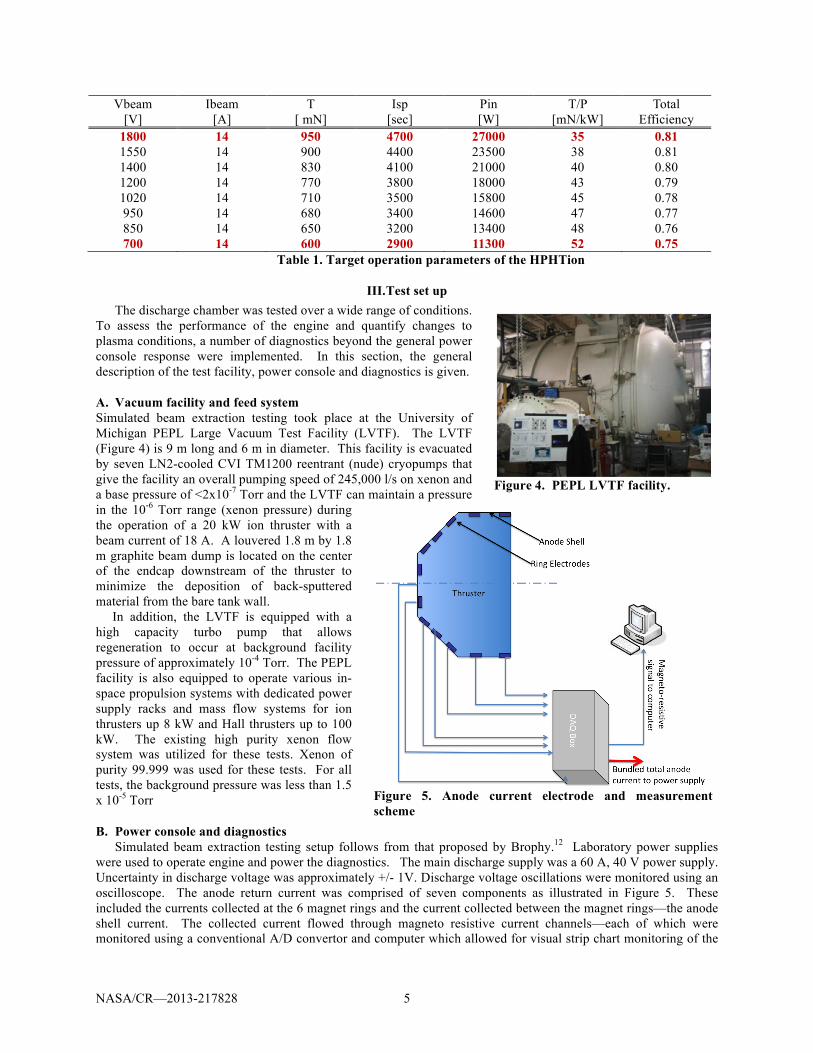
The performance testing with simulated beam extraction allows for optimizing engine performance at the desired operating conditions. Targeted operating conditions are depicted in Table 1. Table 2 represents the idealized upper limit for performance. Here thrust losses such as plume divergence, double to single ratio, and neutralizer power is not incorporated in the calculations shown in the Table. These conditions represent engine throttling at constant beam current. A chief goal of this effort was to maximize thrust to power. This can be achieved in part by reducing the discharge losses. In this engine, optimization efforts target discharge losses less than 120 W/A. The highlighted low beam voltage point represents a very high thrust to power operating condition. Demonstration of operation at such conditions even with limited life is of interest for quicker orbit transfer applications. The 1800 V operating conditions refers to a high-powered, high specific impulse operating condition, compatible with tug-like operations for Mars for example.
Figure 2. Magnetic circuit layout of baseline engine configuration. Aspect ratio not to scale.
Figure 3. Assembled 50 cm hardware minus grids.
NASA/CR—2013-217828 4
Vbeam [V]
Ibeam [A]
T [ mN]
Isp [sec]
Pin [W]
T/P [mN/kW]
Total Efficiency
1800 14 950 4700 27000 35 0.81 1550 14 900 4400 23500 38 0.81 1400 14 830 4100 21000 40 0.80 1200 14 770 3800 18000 43 0.79 1020 14 710 3500 15800 45 0.78 950 14 680 3400 14600 47 0.77 850 14 650 3200 13400 48 0.76 700 14 600 2900 11300 52 0.75
Table 1. Target operation parameters of the HPHTion
III. Test set up The discharge chamber was tested over a wide range of conditions.
To assess the performance of the engine and quantify changes to plasma conditions, a number of diagnostics beyond the general power console response were implemented. In this section, the general description of the test facility, power console and diagnostics is given.
A. Vacuum facility and feed system Simulated beam extraction testing took place at the University of Michigan PEPL Large Vacuum Test Facility (LVTF). The LVTF (Figure 4) is 9 m long and 6 m in diameter. This facility is evacuated by seven LN2-cooled CVI TM1200 reentrant (nude) cryopumps that give the facility an overall pumping speed of 245,000 l/s on xenon and a base pressure of <2x10⁻⁷ Torr and the LVTF can maintain a pressure in the 10-6 Torr range (xenon pressure) during the operation of a 20 kW ion thruster with a beam current of 18 A. A louvered 1.8 m by 1.8 m graphite beam dump is located on the center of the endcap downstream of the thruster to minimize the deposition of back-sputtered material from the bare tank wall. In addition, the LVTF is equipped with a high capacity turbo pump that allows regeneration to occur at background facility pressure of approximately 10-4 Torr. The PEPL facility is also equipped to operate various in-space propulsion systems with dedicated power supply racks and mass flow systems for ion thrusters up 8 kW and Hall thrusters up to 100 kW. The existing high purity xenon flow system was utilized for these tests. Xenon of purity 99.999 was used for these tests. For all tests, the background pressure was less than 1.5 x 10⁻⁵ Torr
B. Power console and diagnostics Simulated beam extraction testing setup follows from that proposed by Brophy.12 Laboratory power supplies
were used to operate engine and power the diagnostics. The main discharge supply was a 60 A, 40 V power supply. Uncertainty in discharge voltage was approximately +/- 1V. Discharge voltage oscillations were monitored using an oscilloscope. The anode return current was comprised of seven components as illustrated in Figure 5. These included the currents collected at the 6 magnet rings and the current collected between the magnet rings—the anode shell current. The collected current flowed through magneto resistive current channels—each of which were monitored using a conventional A/D convertor and computer which allowed for visual strip chart monitoring of the
Figure 4. PEPL LVTF facility.
Figure 5. Anode current electrode and measurement scheme Figure 6. Ion collection grid with array of fixed plasma probes
NASA/CR—2013-217828 5
current distribution to the anode. In this investigation, the discharge current did not exceed 46 A—a self-imposed limit placed on the 50 a cathode. Resistance between ring electrodes and the anode shell was high typically ~Giga-Ohms as indicated by “hi-potting” at 500 V- 1000 V, indicating very good isolation.
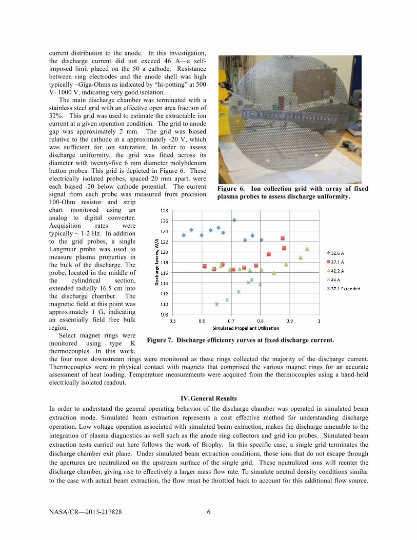
The main discharge chamber was terminated with a stainless steel grid with an effective open area fraction of 32%. This grid was used to estimate the extractable ion current at a given operation condition. The grid to anode gap was approximately 2 mm. The grid was biased relative to the cathode at a approximately -20 V, which was sufficient for ion saturation. In order to assess discharge uniformity, the grid was fitted across its diameter with twenty-five 6 mm diameter molybdenum button probes. This grid is depicted in Figure 6. These electrically isolated probes, spaced 20 mm apart, were each biased -20 below cathode potential. The current signal from each probe was measured from precision 100-Ohm resistor and strip chart monitored using an analog to digital converter. Acquisition rates were typically ~ 1-2 Hz. In addition to the grid probes, a single Langmuir probe was used to measure plasma properties in the bulk of the discharge. The probe, located in the middle of the cylindrical section, extended radially 16.5 cm into the discharge chamber. The magnetic field at this point was approximately 1 G, indicating an essentially field free bulk region.
Select magnet rings were monitored using type K thermocouples. In this work, the four most downstream rings were monitored as these rings collected the majority of the discharge current. Thermocouples were in physical contact with magnets that comprised the various magnet rings for an accurate assessment of heat loading. Temperature measurements were acquired from the thermocouples using a hand-held electrically isolated readout.
IV. General Results In order to understand the general operating behavior of the discharge chamber was operated in simulated beam extraction mode. Simulated beam extraction represents a cost effective method for understanding discharge operation. Low voltage operation associated with simulated beam extraction, makes the discharge amenable to the integration of plasma diagnostics as well such as the anode ring collectors and grid ion probes. Simulated beam extraction tests carried out here follows the work of Brophy. In this specific case, a single grid terminates the discharge chamber exit plane. Under simulated beam extraction conditions, those ions that do not escape through the apertures are neutralized on the upstream surface of the single grid. These neutralized ions will reenter the discharge chamber, giving rise to effectively a larger mass flow rate. To simulate neutral density conditions similar to the case with actual beam extraction, the flow must be throttled back to account for this additional flow source.
Figure 6. Ion collection grid with array of fixed plasma probes to assess discharge uniformity.
Figure 7. Discharge efficiency curves at fixed discharge current.
NASA/CR—2013-217828 6

The relations for the simulated current, the ion transparency to the single grid and the simulated propellant efficiency are therefore:
Jbeam−sim = Jgrid ⋅ϕi
where is the grid transparency and is the total ion flux incident on the grid. Grid transparency may be also
be determined by:
ϕi =Jgrid
Jgrid + Jbeam
The simulated utilization can therefore be calculated:
ηm−sim =ϕi ⋅ Jgrid
m+ Jgrid1−ϕi
ϕi
#
$%
&
'(
along with discharge losses:
ηD =JDVDJbeam−sim
In this manner, thruster operation will be simulated. Studies have shown that this approach replicates actual thruster operation very well.13
A. Discharge performance In order to assess the discharge efficiency, the discharge chamber’s simulated discharge losses and propellant
utilization were determined from grid current measurements, discharge input power, and mass flow rate. The performance curves were acquired using two methods: 1) vary the flow at fixed discharge current 2) vary discharge parameters such as main and cathode flow rates as well as the discharge current at fixed simulated beam current.
In these investigations, discharge voltage varied between 24 and 29 volts nominally. Some operating points at discharge voltages as high as 30 V were also acquired to map out the region beyond the “knee.” Figure 7 is the performance plot obtained by fixing the discharge current and varying the flow. When this is done, the simulated beam current increases as does the utilization. Such plots indicate the simulated beam current range for a given input discharge power. The 37 A and 42.2 A cases follow expected performance trends with knees at just over 0.8 and 0.87 respectively. The 32 A case is somewhat puzzling in that the discharge losses appear to be invariant to changes in flow over a broad range. Here, with changes in flow rate, the discharge power and grid current increase at the same rate. In all cases, these data sets suggest low discharge losses ranging from ~125 W/A to as low as 115 W/A for the baseline configuration. The discharge was also operated at 44 A, which resulted in even lower discharge losses—close to 110 W/A at 0.80 utilization. For comparison, the 37.1 A operating condition case approached this discharge efficiency at the relatively low utilization of 0.67. Since during normal thruster operation, the beam current is typically fixed, it is of interest to plot performance at fixed extractable grid current. Figure 8 illustrates the behavior of the discharge efficiency at fixed simulated beam current. In all cases, the cathode operated in essentially a quiet mode as inferred from peak to peak voltage oscillations on the discharge voltage (oscillations ~5 V average), oscillations in probe current at the grid, and visual observation of the discharge. Simulated beam currents up to nearly 12 A were achievable with the existing configuration. Higher beam currents require operation at higher discharge currents. The existing discharge cathode is limited to around 50 A of emission current. A somewhat larger cathode emission current will be required to achieve the 14 A beam case (~55-60 A). These plots also indicate the relatively low discharge losses—in this case occurring less than 120 W/A. At the 11.9 A condition, losses were around 110 W/A at a utilization of nearly 0.9. These discharge losses compare with optimized engines such as NEXT , which operates at around 125 W/A and 0.89 utilization at full power.14 In any event, the performance values inferred from simulated beam extraction at the lower beam currents compare well with the design target of ~110 W/A at utilizations of around 0.92 for the 14 A beam case. The data suggests that the 14 A performance target is achievable based as the performance curve knee tends to shift with increasing discharge current towards higher utilization. The low discharge losses overall appear to be attributed to three factors: 1) Large discharge chamber translates into longer characteristic diffusion times. 2) Optimal magnetic circuit featuring 6 rings minimizes losses 3) Discharge chamber is masked down by 15 percent.
ϕi Jgrid
NASA/CR—2013-217828 7
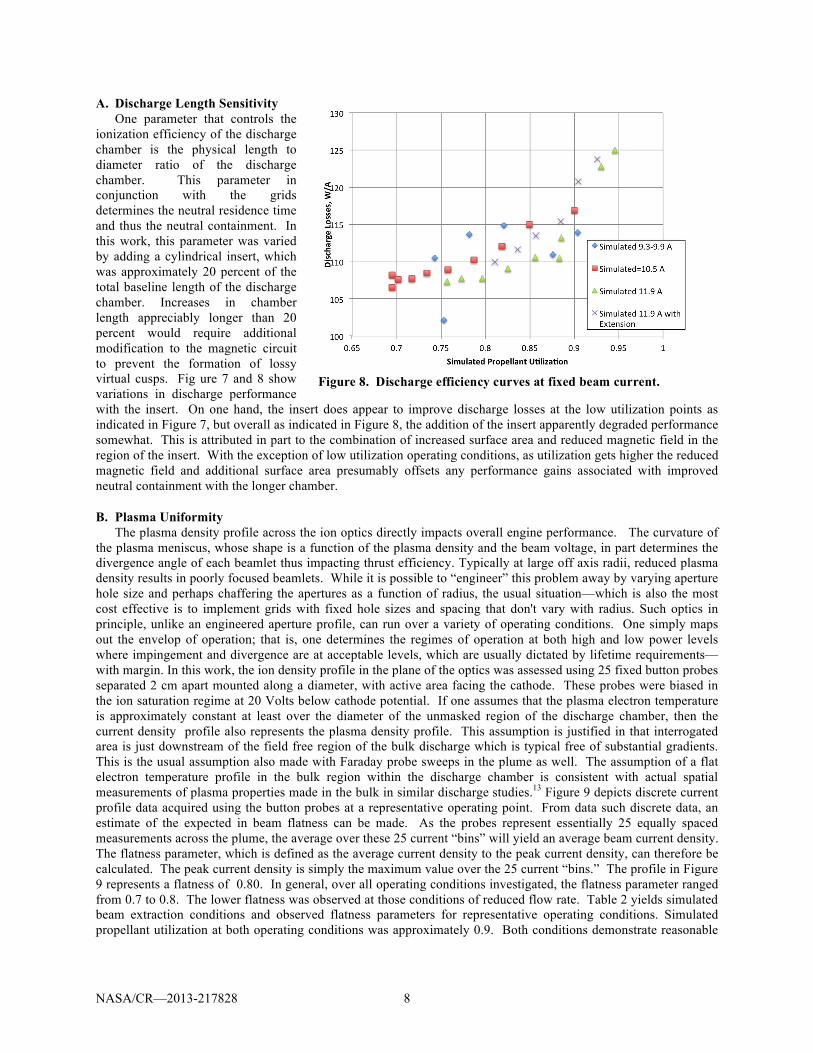
A. Discharge Length Sensitivity One parameter that controls the
ionization efficiency of the discharge chamber is the physical length to diameter ratio of the discharge chamber. This parameter in conjunction with the grids determines the neutral residence time and thus the neutral containment. In this work, this parameter was varied by adding a cylindrical insert, which was approximately 20 percent of the total baseline length of the discharge chamber. Increases in chamber length appreciably longer than 20 percent would require additional modification to the magnetic circuit to prevent the formation of lossy virtual cusps. Fig ure 7 and 8 show variations in discharge performance with the insert. On one hand, the insert does appear to improve discharge losses at the low utilization points as indicated in Figure 7, but overall as indicated in Figure 8, the addition of the insert apparently degraded performance somewhat. This is attributed in part to the combination of increased surface area and reduced magnetic field in the region of the insert. With the exception of low utilization operating conditions, as utilization gets higher the reduced magnetic field and additional surface area presumably offsets any performance gains associated with improved neutral containment with the longer chamber.
B. Plasma Uniformity The plasma density profile across the ion optics directly impacts overall engine performance. The curvature of
the plasma meniscus, whose shape is a function of the plasma density and the beam voltage, in part determines the divergence angle of each beamlet thus impacting thrust efficiency. Typically at large off axis radii, reduced plasma density results in poorly focused beamlets. While it is possible to “engineer” this problem away by varying aperture hole size and perhaps chaffering the apertures as a function of radius, the usual situation—which is also the most cost effective is to implement grids with fixed hole sizes and spacing that don't vary with radius. Such optics in principle, unlike an engineered aperture profile, can run over a variety of operating conditions. One simply maps out the envelop of operation; that is, one determines the regimes of operation at both high and low power levels where impingement and divergence are at acceptable levels, which are usually dictated by lifetime requirements—with margin. In this work, the ion density profile in the plane of the optics was assessed using 25 fixed button probes separated 2 cm apart mounted along a diameter, with active area facing the cathode. These probes were biased in the ion saturation regime at 20 Volts below cathode potential. If one assumes that the plasma electron temperature is approximately constant at least over the diameter of the unmasked region of the discharge chamber, then the current density profile also represents the plasma density profile. This assumption is justified in that interrogated area is just downstream of the field free region of the bulk discharge which is typical free of substantial gradients. This is the usual assumption also made with Faraday probe sweeps in the plume as well. The assumption of a flat electron temperature profile in the bulk region within the discharge chamber is consistent with actual spatial measurements of plasma properties made in the bulk in similar discharge studies.13 Figure 9 depicts discrete current profile data acquired using the button probes at a representative operating point. From data such discrete data, an estimate of the expected in beam flatness can be made. As the probes represent essentially 25 equally spaced measurements across the plume, the average over these 25 current “bins” will yield an average beam current density. The flatness parameter, which is defined as the average current density to the peak current density, can therefore be calculated. The peak current density is simply the maximum value over the 25 current “bins.” The profile in Figure 9 represents a flatness of 0.80. In general, over all operating conditions investigated, the flatness parameter ranged from 0.7 to 0.8. The lower flatness was observed at those conditions of reduced flow rate. Table 2 yields simulated beam extraction conditions and observed flatness parameters for representative operating conditions. Simulated propellant utilization at both operating conditions was approximately 0.9. Both conditions demonstrate reasonable
Figure 8. Discharge efficiency curves at fixed beam current.
NASA/CR—2013-217828 8

flatness even at such high utilizations. The flatness parameter numbers reported here are conservative owing to the discrete nature of the data, which for a finite set of probes would tend to overly represent peaked features.
Discharge Voltage, V Discharge Current, A Sim. Beam Current, A Flatness 27.2 37.1 8.7 .7 28.0 42.2 10.4 .7
Table 2: Simulated beam extraction conditions and observed flatness parameters.
C. Current distribution at magnet rings In additional to mapping general performance of the discharge chamber and plasma uniformity, overall engine
operating characteristics and behavior is intimately tied to cathode operating mode and the magnetic circuit. The majority of the discharge current is collected at the various magnet rings. The current distribution in turn determines the spatial distribution of the plasma in the discharge chamber. This follows from the fact that in ring cusp engines, peripheral ionization takes place at the magnet rings. Collection of plasma current at and subsequent diffusion of plasma from these localized plasma sources determine everything from the bulk plasma spatial distribution to discharge stability to the thermal limitations of the device. In this work, ring stainless steel electrodes covered each magnet ring. These electrodes allowed for monitoring of the current distribution as a function of operating condition. Current to anode surfaces between magnet rings—denoted the “shell”—was also monitored in this work. Figure 10a illustrates the behavior of the currents at the various rings as at three different propellant utilizations but at a fixed simulated beam current of 11.9 A. The currents are normalized to the total discharge current. As can be seen here, the majority of the current collection occurs at the four most downstream magnet rings, giving the current collection profile a parabolic shape. The shell collects 13-15 percent of the discharge current and constitutes a higher collection fraction at the highest utilization. Owing to the differences in collection area, the current density profile differs somewhat from the raw current profile. Here, the behavior of the current density is estimated by dividing the collected current at a given ring by the circumference of that particular magnet ring electrode. A plot of this parameter is shown in Figure 10 b. It should be pointed out that this parameter is a rough estimate as the actual collection area depends on the spatial variations in the magnetic field at the cusp. This current density parameter plot suggests current density is higher in the conical section and drops off towards the cylindrical section. As can be seen in Figure 10, the current collection profile does not change appreciably with increasing utilization. In all cases, ring 3 appears to be the dominant ring from both a raw collection and current density standpoint. The profiles presented in Figure 10 were prevalent over
Figure 9. Ion current profile across simulated optics. Flatness =0.8.
Figure 10a. Variation in anode current distribution with utilization.
NASA/CR—2013-217828 9
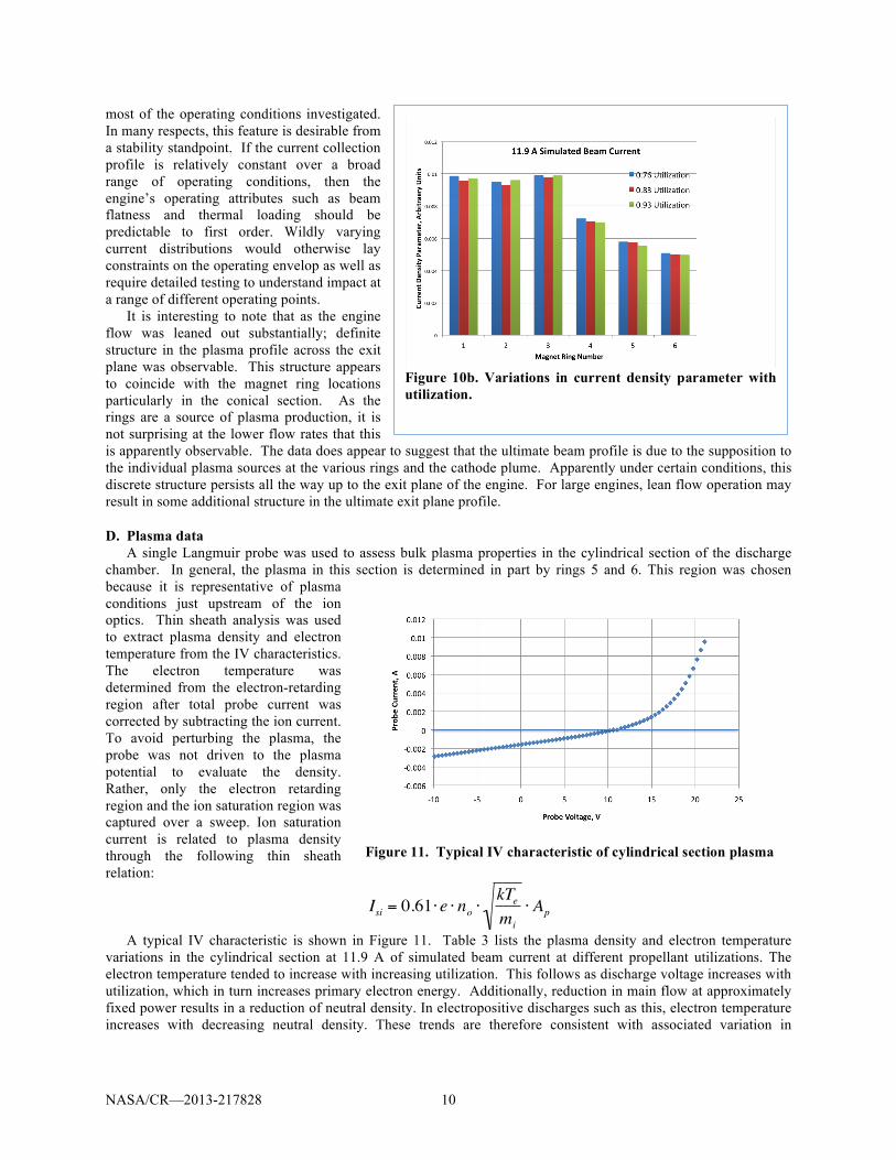
most of the operating conditions investigated. In many respects, this feature is desirable from a stability standpoint. If the current collection profile is relatively constant over a broad range of operating conditions, then the engine’s operating attributes such as beam flatness and thermal loading should be predictable to first order. Wildly varying current distributions would otherwise lay constraints on the operating envelop as well as require detailed testing to understand impact at a range of different operating points.
It is interesting to note that as the engine flow was leaned out substantially; definite structure in the plasma profile across the exit plane was observable. This structure appears to coincide with the magnet ring locations particularly in the conical section. As the rings are a source of plasma production, it is not surprising at the lower flow rates that this is apparently observable. The data does appear to suggest that the ultimate beam profile is due to the supposition to the individual plasma sources at the various rings and the cathode plume. Apparently under certain conditions, this discrete structure persists all the way up to the exit plane of the engine. For large engines, lean flow operation may result in some additional structure in the ultimate exit plane profile.
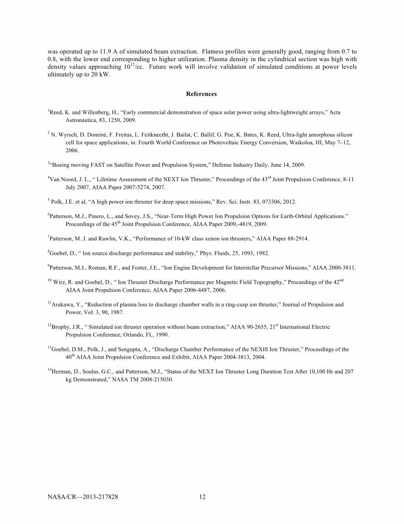
D. Plasma data A single Langmuir probe was used to assess bulk plasma properties in the cylindrical section of the discharge
chamber. In general, the plasma in this section is determined in part by rings 5 and 6. This region was chosen because it is representative of plasma conditions just upstream of the ion optics. Thin sheath analysis was used to extract plasma density and electron temperature from the IV characteristics. The electron temperature was determined from the electron-retarding region after total probe current was corrected by subtracting the ion current. To avoid perturbing the plasma, the probe was not driven to the plasma potential to evaluate the density. Rather, only the electron retarding region and the ion saturation region was captured over a sweep. Ion saturation current is related to plasma density through the following thin sheath relation:
€
Isi = 0.61⋅e ⋅ no ⋅kTemi
⋅ Ap
A typical IV characteristic is shown in Figure 11. Table 3 lists the plasma density and electron temperature variations in the cylindrical section at 11.9 A of simulated beam current at different propellant utilizations. The electron temperature tended to increase with increasing utilization. This follows as discharge voltage increases with utilization, which in turn increases primary electron energy. Additionally, reduction in main flow at approximately fixed power results in a reduction of neutral density. In electropositive discharges such as this, electron temperature increases with decreasing neutral density. These trends are therefore consistent with associated variation in
Figure 11. Typical IV characteristic of cylindrical section plasma
Figure 10b. Variations in current density parameter with utilization.
NASA/CR—2013-217828 10

discharge input parameters. The plasma density on the other hand remains relatively constant over the variation in utilization at least within experimental uncertainty in this measurement. As shown here, the electron density is fairly high, nearly 1012/cc. The relative constancy of the plasma density with increasing utilization is consistent with the relative invariance in current collected at the cylindrical section magnet rings. Presumably, increases in electron temperature are not sufficient to give rise to appreciable rises in the electron density. Likely this is due to reduced main flow at the higher utilizations. Even though the plasma electron temperature increases, the ionization rate is directly proportional to the neutral pressure, which is decreased in order to achieve higher utilization. These two effects apparently offset each other.
Utilization Ne, /cc Te, eV 0.75 6.35 x 10¹¹ 4.19 0.83 6.15 x 10¹¹ 4.94 0.93 6.36 x 10¹¹ 5.84
Table 3: Langmuir Probe Data—11. 9 A Simulated Beam Current.
E. Thermal Data The temperature of the four most
downstream magnet rings was monitored as a function of operating condition using type K thermocouples. These rings were of interest primarily because the majority of the plasma current was collected there and therefore these rings were expected to experience the greatest thermal loads. The magnets utilized in this study had an upper temperature operating limit of 600 C. In this work, the magnet rings monitored never exceeded ~350 C, indicating at least over the regime characterized and reported herein, the magnets were always well below magnet thermal limits. Figure 12 illustrates typical thermal behavior; in this case at the highest discharge current condition investigated corresponding to 11.9 A simulated beam current. As can be seen from the figure, the difference between the hottest measured ring and the coolest is about 40 C. Though the difference in temperatures between the various rings is relatively small, the temperature profile is somewhat different from the observed current profiles discussed earlier. In this case, the temperature peak is at ring 5, not ring 3 as was observed from the current profiles. In general, power deposition should follow the current density variations (see Figure 10b). The temperature profile does not follow trends in the current density. The difference between the two profiles can be reconciled if one considers the geometry of the magnet rings. Rings 3 and 4 are mounted on the conical section and are thus canted such that the view factors intersect the optics, which allows for radiative cooling as the radiation can actually escape. Ring 5 on the other hand is mounted on the cylindrical section and thus the ring’s view factor includes its opposite side and hot discharge chamber wall material. In this regard, radiation losses through the grid is not direct, thus it runs hotter. The temperature difference between ring three and ring four is likely due to differences in current density. All in all, the thermal data reflects the notion that current collection alone is not the only driver in operating temperature, rather geometrical considerations are also important as apparently demonstrated in this work.
V. Concluding Remarks The discharge of a 50 cm ion thruster was characterized using simulated beam extraction. The discharge
chamber is designed for single engine operation up to 25 kW. Discharge losses as low as 110 W/A were observed. Low discharge losses are desirable at intermediate powers in that it provides a pathway to higher thrust to power. It was observed that the current collection profile at the various magnet rings did not vary appreciably over a wide flow rate and discharge power range. Magnet temperatures remained well below stabilization limits as the discharge
Figure 12. Temperature profiles at 11.9 A simulated beam
NASA/CR—2013-217828 11
was operated up to 11.9 A of simulated beam extraction. Flatness profiles were generally good, ranging from 0.7 to 0.8, with the lower end corresponding to higher utilization. Plasma density in the cylindrical section was high with density values approaching 1012/cc. Future work will involve validation of simulated conditions at power levels ultimately up to 20 kW.
References
1Reed, K. and Willenberg, H., “Early commercial demonstration of space solar power using ultra-lightweight arrays,” Acta
Astronautica, 83, 1250, 2009.
2 N. Wyrsch, D. Dominé, F. Freitas, L. Feitknectht, J. Bailat, C. Ballif, G. Poe, K. Bates, K. Reed, Ultra-light amorphous silicon cell for space applications, in: Fourth World Conference on Photovoltaic Energy Conversion, Waikoloa, HI, May 7–12, 2006.
3“Boeing moving FAST on Satellite Power and Propulsion System,” Defense Industry Daily, June 14, 2009.
4Van Noord, J. L., “ Lifetime Assessment of the NEXT Ion Thruster,” Proceedings of the 43rd Joint Propulsion Conference, 8-11 July 2007, AIAA Paper 2007-5274, 2007.
5 Polk, J.E. et al, “A high power ion thruster for deep space missions,” Rev. Sci. Instr. 83, 073306, 2012.
6Patterson, M.J., Pinero, L., and Sovey, J.S., “Near-Term High Power Ion Propulsion Options for Earth-Orbital Applications.” Proceedings of the 45th Joint Propulsion Conference, AIAA Paper 2009,-4819, 2009.
7Patterson, M. J. and Rawlin, V.K., “Performance of 10-kW class xenon ion thrusters,” AIAA Paper 88-2914.
8Goebel, D., “ Ion source discharge performance and stability,” Phys. Fluids, 25, 1093, 1982.
9Patterson, M.J., Roman, R.F., and Foster, J.E., “Ion Engine Development for Interstellar Precursor Missions,” AIAA 2000-3811.
10 Wirz, R. and Goebel, D., “ Ion Thruster Discharge Performance per Magnetic Field Topography,” Proceedings of the 42nd AIAA Joint Propulsion Conference, AIAA Paper 2006-4487, 2006.
11Arakawa, Y., “Reduction of plasma loss to discharge chamber walls in a ring-cusp ion thruster,” Journal of Propulsion and Power, Vol. 3, 90, 1987.
12Brophy, J.R., “ Simulated ion thruster operation without beam extraction,” AIAA 90-2655, 21st International Electric Propulsion Conference, Orlando, FL, 1990.
13Goebel, D.M., Polk, J., and Sengupta, A., “Discharge Chamber Performance of the NEXIS Ion Thruster,” Proceedings of the 40th AIAA Joint Propulsion Conference and Exhibit, AIAA Paper 2004-3813, 2004.
14Herman, D., Soulas, G.C., and Patterson, M.J., “Status of the NEXT Ion Thruster Long Duration Test After 10,100 Hr and 207 kg Demonstrated,” NASA TM 2008-215030.
NASA/CR—2013-217828 12

REPORT DOCUMENTATION PAGE Form Approved OMB No. 0704-0188
The public reporting burden for this collection of information is estimated to average 1 hour per response, including the time for reviewing instructions, searching existing data sources, gathering and maintaining the data needed, and completing and reviewing the collection of information. Send comments regarding this burden estimate or any other aspect of this collection of information, including suggestions for reducing this burden, to Department of Defense, Washington Headquarters Services, Directorate for Information Operations and Reports (0704-0188), 1215 Jefferson Davis Highway, Suite 1204, Arlington, VA 22202-4302. Respondents should be aware that notwithstanding any other provision of law, no person shall be subject to any penalty for failing to comply with a collection of information if it does not display a currently valid OMB control number. PLEASE DO NOT RETURN YOUR FORM TO THE ABOVE ADDRESS.
1. REPORT DATE (DD-MM-YYYY) 01-06-2013
2. REPORT TYPE Final Contractor Report
3. DATES COVERED (From - To)
4. TITLE AND SUBTITLE Simulated Beam Extraction Performance Characterization of a 50-cm Ion Thruster Discharge
5a. CONTRACT NUMBER NNX10CF59P; NNX11CC56C
5b. GRANT NUMBER
5c. PROGRAM ELEMENT NUMBER
6. AUTHOR(S) Foster, John, E.; Hubble, Aimee; Nowak-Gucker, Sarah; Davis, Chris; Peterson, Peter; Viges, Eric; Chen, Dave
5d. PROJECT NUMBER
5e. TASK NUMBER
5f. WORK UNIT NUMBER WBS 295670.01.04.05
7. PERFORMING ORGANIZATION NAME(S) AND ADDRESS(ES) The University of Michigan
8. PERFORMING ORGANIZATION REPORT NUMBER E-18579
9. SPONSORING/MONITORING AGENCY NAME(S) AND ADDRESS(ES) National Aeronautics and Space Administration Washington, DC 20546-0001
10. SPONSORING/MONITOR'S ACRONYM(S) NASA
11. SPONSORING/MONITORING REPORT NUMBER NASA/CR-2013-217828
12. DISTRIBUTION/AVAILABILITY STATEMENT Unclassified-Unlimited Subject Category: 20 Available electronically at http://www.sti.nasa.gov This publication is available from the NASA Center for AeroSpace Information, 443-757-5802
13. SUPPLEMENTARY NOTES
14. ABSTRACT A 50 cm ion thruster is being developed to operate at >65 percent total efficiency at 11 kW, 2700 s Isp and over 25 kW, 4500 s Isp at a total efficiency of >75 percent. The engine is being developed to address the need for a multimode system that can provide a range of thrust-to-power to service national and commercial near-earth onboard propulsion needs such as station-keeping and orbit transfer. Operating characteristics of the 50 cm ion thruster were measured under simulated beam extraction. The discharge current distribution at the various magnet rings was measured over a range of operating conditions. The relationship between the anode current distribution and the resulting plasma uniformity and ion flux measured at the thruster exit plane is discussed. The thermal envelope will also be investigated through the monitoring of magnet temperatures over the range of discharge powers investigated. Discharge losses as a function of propellant utilization was also characterized at multiple simulated beam currents. Bulk plasma conditions such as electron temperature and electron density near engine centerline was measured over a range of operating conditions using an internal Langmuir probe. Sensitivity of discharge performance to chamber length is also discussed. This data acquired from this discharge study will be used in the refinement of a throttle table in anticipation for eventual beam extraction testing. 15. SUBJECT TERMS Propulsion; Electric propulsion; Advanced propulsion; In-space propulsion; Thruster; Xenon; Ion propulsion
16. SECURITY CLASSIFICATION OF: 17. LIMITATION OF ABSTRACT UU
18. NUMBER OF PAGES
20
19a. NAME OF RESPONSIBLE PERSON STI Help Desk (email:[email protected])
a. REPORT U
b. ABSTRACT U
c. THIS PAGE U
19b. TELEPHONE NUMBER (include area code) 443-757-5802
Standard Form 298 (Rev. 8-98)Prescribed by ANSI Std. Z39-18