Embed Size (px)
Citation preview

Preface, Contents
General Technical Specifications1
Racks2
Power Supply Modules3
Digital Modules4
Analog Modules5
Interface Modules6
IM 463-27
PROFIBUS DP Master InterfaceIM 467/IM 467 FO
8Cable Duct and FanSubassemblies
9
RS 485 Repeater10
CPUs for M7-40011
M7-400 Expansions12
Interface Submodules13
AppendicesLEERER
Parameter Sets for Signal Modules ADiagnostic Data of the Signal Modules B
Spare Parts and Accessories CGuidelines for Handling Electro-static Sensitive Devices (ESD) D
List of Abbreviations E
Glossary, Index
S7-400, M7-400 ProgrammableControllersModule Specifications
Reference Manual
SIMATIC
This manual is part of the documentation package with the order number:6ES7498-8AA03-8BA0
Edition 12/2002A5E00069467-06
!Danger
indicates that death, severe personal injury or substantial property damage will result if proper precau-tions are not taken.
!Warning
indicates that death, severe personal injury or substantial property damage can result if properprecautions are not taken.
!Caution
indicates that minor personal injury can result if proper precautions are not taken.
Caution
indicates that property damage can result if proper precautions are not taken.
Notice
draws your attention to particularly important information on the product, handling the product, or to aparticular part of the documentation.
Qualified PersonnelOnly qualified personnel should be allowed to install and work on this equipment. Qualified personsare defined as persons who are authorized to commission, to ground and to tag circuits, equipment, andsystems in accordance with established safety practices and standards.
Correct UsageNote the following:
!Warning
This device and its components may only be used for the applications described in the catalog or thetechnical description, and only in connection with devices or components from other manufacturerswhich have been approved or recommended by Siemens.
This product can only function correctly and safely if it is transported, stored, set up, and installedcorrectly, and operated and maintained as recommended.
TrademarksSIMATIC, SIMATIC HMI and SIMATIC NET are registered trademarks of SIEMENS AG.
Third parties using for their own purposes any other names in this document which refer to trademarksmight infringe upon the rights of the trademark owners.
Safety GuidelinesThis manual contains notices intended to ensure personal safety, as well as to protect the products andconnected equipment against damage. These notices are highlighted by the symbols shown below andgraded according to severity by the following texts:
We have checked the contents of this manual for agreementwith the hardware and software described. Since deviationscannot be precluded entirely, we cannot guarantee fullagreement. However, the data in this manual are reviewedregularly and any necessary corrections included insubsequent editions. Suggestions for improvement arewelcomed.
Disclaim of LiabilityCopyright Siemens AG 1999-2002 All rights reserved
The reproduction, transmission or use of this document or itscontents is not permitted without express written authority.Offenders will be liable for damages. All rights, includingrights created by patent grant or registration of a utility modelor design, are reserved.
Siemens AGBereich Automation and DrivesGeschaeftsgebiet Industrial Automation SystemsPostfach 4848, D- 90327 Nuernberg
Siemens AG 1999-2002Technical data subject to change.
Siemens Aktiengesellschaft A5E000069467-06
iiiS7-400, M7-400 Programmable Controllers Module SpecificationsA5E00069467-06
Preface
Purpose of the Manual
The manual contains reference information on operator actions, descriptions offunctions and technical specifications of the central processing units, power supplymodules and interface modules of the S7-400.
How to configure, assemble and wire these modules in an S7-400 or M7-400system is described in the installation manuals for each system.
Required Basic Knowledge
You will need general knowledge of automation to understand this manual.
Target Group
This manual is aimed at people with the required qualifications to commission,operate and maintain the products described.
Where is this Manual valid?
The manual is valid for the S7-400, M7-400 programmable controller.
Changes Compared to the Previous Version
Since the previous version of the “Module Specifications” reference manual, thefollowing changes have been made:
• The descriptions of the CPU and the CPU relevant products and topics havebeen put together in one manual, “CPU Specifications”.
• The descriptions of the H CPUs and their associated products and topics havebeen moved to the manual “S7–400 H Programmable Controller, RedundantSystems”
Note: The previous version of this “Module Specifications” reference manual canbe recognized by the number in the footer: A5E00069467-05.
The current number is: A5E00069467-06.
Preface
ivS7-400, M7-400 Programmable Controllers Module Specifications
A5E00069467-06
Certification
The SIMATIC S7-400 product range has the following certificates:
• Underwriters Laboratories, Inc.: UL 508 (Industrial Control Equipment)
• Canadian Standards Association: CSA C22.2 Nummer 142 (Process ControlEquipment)
• Factory Mutual Research: Approval Standard Class Number 3611.
You can find details on the certificates and approvals in the reference manual“Module Specifications”.
CE Labeling
The SIMATIC S7-400 product range complies with the requirements and protectionobjectives of the following EU directives:
• EC low voltage directive 73/23/EEC
• EC electromagnetic compatibility directive 89/336/EEC
C-Tick Mark
The SIMATIC S7-400 product range complies with the requirements of theAS/NZS 2064 standard (Australia and New Zealand).
Standards
The SIMATIC S7-400 product range complies with the requirements and criteria ofthe IEC 61131-2.
Place of this Documentation in the Information Environment
This manual forms part of the S7-400 and M7-400 documentation.
System Documentation Package
S7-400/M7-400 • S7-400, M7-400 Programmable Controllers; Hardware andInstallation
• S7-400, M7-400 Programmable Controllers; Module Specifications
• Automation System S7-400 CPU Data
• S7-400 Instruction List
Preface
vS7-400, M7-400 Programmable Controllers Module SpecificationsA5E00069467-06
Finding Your Way
To help you find special information quickly, the manual contains the followingaccess aids:
• At the start of the manual you will find a complete table of contents and a list ofthe diagrams and tables that appear in the manual.
• An overview of the contents of each section is provided in the left column oneach page of each chapter.
• You will find a glossary in the appendix at the end of the manual. The glossarycontains definitions of the main technical terms used in the manual.
• At the end of the manual you will find a comprehensive index which gives yourapid access to the information you need.
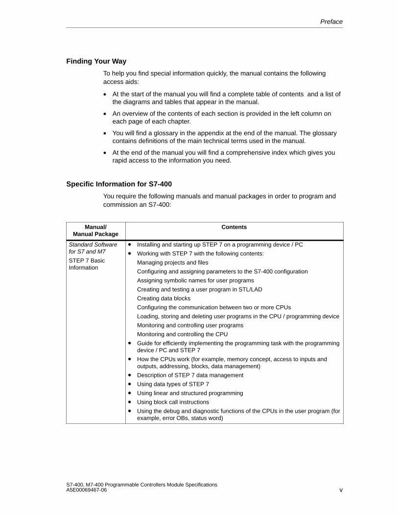
Specific Information for S7-400
You require the following manuals and manual packages in order to program andcommission an S7-400:
Manual/Manual Package
Contents
Standard Softwarefor S7 and M7
STEP 7 BasicInformation
• Installing and starting up STEP 7 on a programming device / PC
• Working with STEP 7 with the following contents:
Managing projects and files
Configuring and assigning parameters to the S7-400 configuration
Assigning symbolic names for user programs
Creating and testing a user program in STL/LAD
Creating data blocks
Configuring the communication between two or more CPUs
Loading, storing and deleting user programs in the CPU / programming device
Monitoring and controlling user programs
Monitoring and controlling the CPU
• Guide for efficiently implementing the programming task with the programmingdevice / PC and STEP 7
• How the CPUs work (for example, memory concept, access to inputs andoutputs, addressing, blocks, data management)
• Description of STEP 7 data management
• Using data types of STEP 7
• Using linear and structured programming
• Using block call instructions
• Using the debug and diagnostic functions of the CPUs in the user program (forexample, error OBs, status word)
Preface
viS7-400, M7-400 Programmable Controllers Module Specifications
A5E00069467-06
Manual/Manual Package
Contents
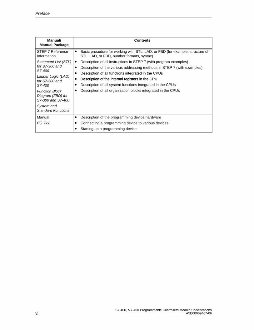
STEP 7 ReferenceInformation
Statement List (STL)for S7-300 andS7-400
Ladder Logic (LAD)
• Basic procedure for working with STL, LAD, or FBD (for example, structure ofSTL, LAD, or FBD, number formats, syntax)
• Description of all instructions in STEP 7 (with program examples)
• Description of the various addressing methods in STEP 7 (with examples)
• Description of all functions integrated in the CPUs
• Description of the internal registers in the CPUfor S7-300 andS7-400
Function BlockDiagram (FBD) forS7-300 and S7-400
System andStandard Functions
Description of the internal registers in the CPU
• Description of all system functions integrated in the CPUs
• Description of all organization blocks integrated in the CPUs
Manual
PG 7xx
• Description of the programming device hardware
• Connecting a programming device to various devices
• Starting up a programming device
Preface
viiS7-400, M7-400 Programmable Controllers Module SpecificationsA5E00069467-06
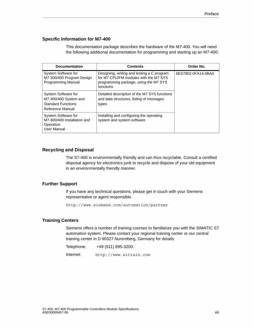
Specific Information for M7-400
This documentation package describes the hardware of the M7-400. You will needthe following additional documentation for programming and starting up an M7-400:
Documentation Contents Order No.
System Software forM7-300/400 Program DesignProgramming Manual
Designing, writing and testing a C programfor M7 CPU/FM modules with the M7 SYSprogramming package, using the M7 SYSfunctions
6ES7802-0FA14-0BA0
System Software forM7-300/400 System andStandard FunctionsReference Manual
Detailed description of the M7 SYS functionsand data structures, listing of messagestypes
System Software forM7-300/400 Installation andOperationUser Manual
Installing and configuring the operatingsystem and system software
Recycling and Disposal
The S7-400 is environmentally friendly and can thus recyclable. Consult a certifieddisposal agency for electronics junk to recycle and dispose of your old equipmentin an environmentally friendly manner.
Further Support
If you have any technical questions, please get in touch with your Siemensrepresentative or agent responsible.
http://www.siemens.com/automation/partner
Training Centers
Siemens offers a number of training courses to familiarize you with the SIMATIC S7automation system. Please contact your regional training center or our centraltraining center in D 90327 Nuremberg, Germany for details:
Telephone: +49 (911) 895-3200.
Internet: http://www.sitrain.com
Preface
viiiS7-400, M7-400 Programmable Controllers Module Specifications
A5E00069467-06
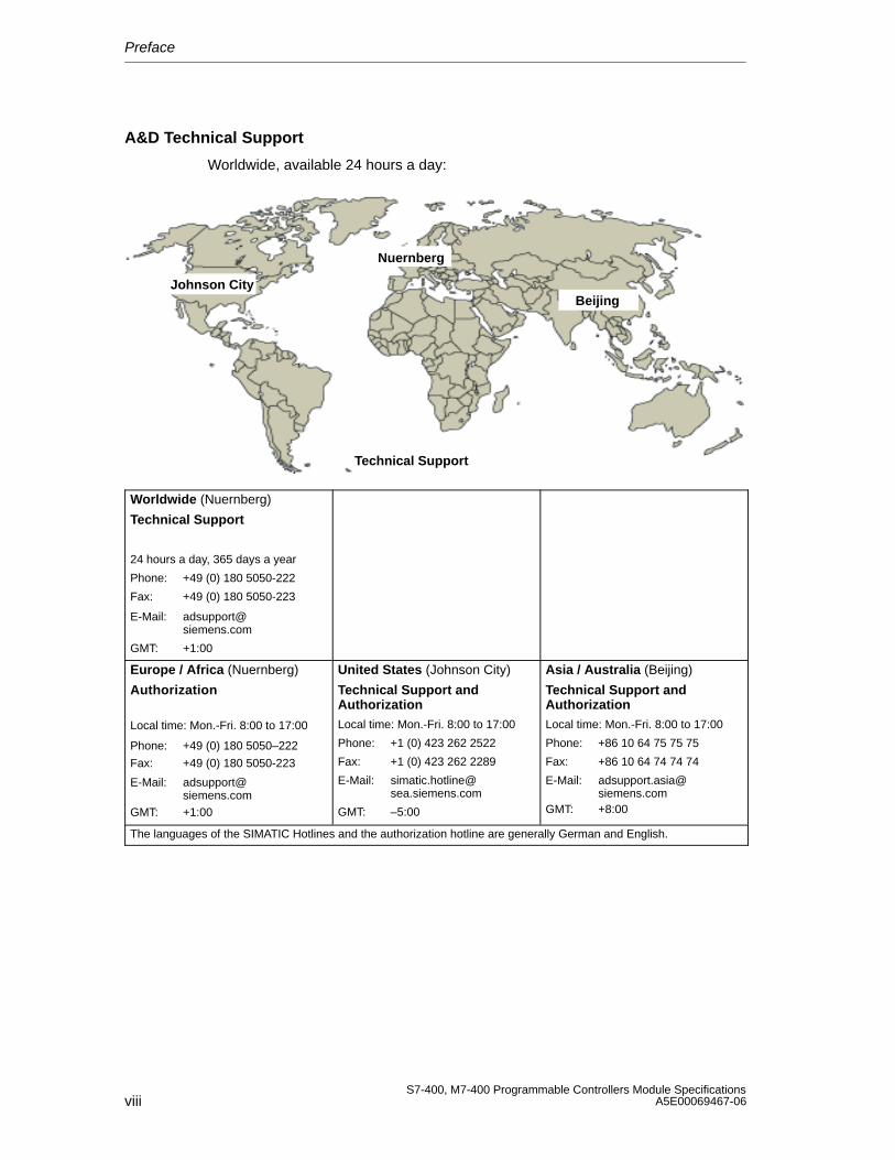
A&D Technical Support
Worldwide, available 24 hours a day:
Johnson City
Nuernberg
Beijing
Technical Support
Worldwide (Nuernberg)
Technical Support
24 hours a day, 365 days a year
Phone: +49 (0) 180 5050-222
Fax: +49 (0) 180 5050-223
E-Mail: [email protected]
GMT: +1:00
Europe / Africa (Nuernberg)
Authorization
Local time: Mon.-Fri. 8:00 to 17:00
Phone: +49 (0) 180 5050–222
Fax: +49 (0) 180 5050-223
E-Mail: [email protected]
GMT: +1:00
United States (Johnson City)
Technical Support andAuthorizationLocal time: Mon.-Fri. 8:00 to 17:00
Phone: +1 (0) 423 262 2522
Fax: +1 (0) 423 262 2289
E-Mail: [email protected]
GMT: –5:00
Asia / Australia (Beijing)
Technical Support andAuthorizationLocal time: Mon.-Fri. 8:00 to 17:00
Phone: +86 10 64 75 75 75
Fax: +86 10 64 74 74 74
E-Mail: [email protected]
GMT: +8:00
The languages of the SIMATIC Hotlines and the authorization hotline are generally German and English.
Preface
ixS7-400, M7-400 Programmable Controllers Module SpecificationsA5E00069467-06
Service & Support on the Internet
In addition to our documentation, we offer our Know-how online on the internet at:
http://www.siemens.com/automation/service&support
where you will find the following:
• The newsletter, which constantly provides you with up–to–date information onyour products.
• The right documents via our Search function in Service & Support.
• A forum, where users and experts from all over the world exchange theirexperiences.
• Your local representative for Automation & Drives via our representativesdatabase.
• Information on field service, repairs, spare parts and more under “Services”.

Preface
xS7-400, M7-400 Programmable Controllers Module Specifications
A5E00069467-06
xiS7-400, M7-400 Programmable Controllers Module SpecificationsA5E00069467-06
Contents
1 General Technical Specifications 1-1. . . . . . . . . . . . . . . . . . . . . . . . . . . . . . . . . . . . . . . . .
1.1 Standards and Approvals 1-2. . . . . . . . . . . . . . . . . . . . . . . . . . . . . . . . . . . . . . . . .
1.2 Electromagnetic Compatibility 1-6. . . . . . . . . . . . . . . . . . . . . . . . . . . . . . . . . . . . .
1.3 Shipping and Storage Conditions for Modules and Backup Batteries 1-9. . . .
1.4 Mechanical and Ambient Climatic Conditions for Operating the S7-400/M7-400 1-11. . . . . . . . . . . . . . . . . . . . . . . . . . . . . . . . . .
1.5 Information on Insulation Tests, Protection Class and Degree of Protection 1-15. . . . . . . . . . . . . . . . . . . . . . . . . . . . . . . . . . . . . . . . . .
2 Racks 2-1. . . . . . . . . . . . . . . . . . . . . . . . . . . . . . . . . . . . . . . . . . . . . . . . . . . . . . . . . . . . . . . . . .
2.1 Function and Structure of the Racks 2-2. . . . . . . . . . . . . . . . . . . . . . . . . . . . . . . .
2.2 The Racks UR1; (6ES7400-1TA01-0AA0) and UR2; (6ES7400-1JA01-0AA0) 2-3. . . . . . . . . . . . . . . . . . . . . . . . . . . . . . . . . . . . .
2.3 The Rack UR2-H; (6ES7400-2JA00-0AA0) 2-5. . . . . . . . . . . . . . . . . . . . . . . . . .
2.4 The Rack CR2; (6ES7401-2TA01-0AA0) 2-7. . . . . . . . . . . . . . . . . . . . . . . . . . . .
2.5 The Rack CR3; (6ES7401-2TA01-0AA0) 2-8. . . . . . . . . . . . . . . . . . . . . . . . . . . .
2.6 The Racks ER1; (6ES7403-1TA01-0AA0) and ER2; (6ES7403-1JA01-0AA0) 2-9. . . . . . . . . . . . . . . . . . . . . . . . . . . . . . . . .
3 Power Supply Modules 3-1. . . . . . . . . . . . . . . . . . . . . . . . . . . . . . . . . . . . . . . . . . . . . . . . . .
3.1 Common Characteristics of the Power Supply Modules 3-2. . . . . . . . . . . . . . .
3.2 Redundant Power Supply Modules 3-4. . . . . . . . . . . . . . . . . . . . . . . . . . . . . . . . .
3.3 Backup Battery (Option) 3-6. . . . . . . . . . . . . . . . . . . . . . . . . . . . . . . . . . . . . . . . . .
3.4 Controls and Indicators 3-8. . . . . . . . . . . . . . . . . . . . . . . . . . . . . . . . . . . . . . . . . . .
3.5 Fault/Error Messages via LEDs 3-13. . . . . . . . . . . . . . . . . . . . . . . . . . . . . . . . . . . .
3.6 Power Supply Module PS 407 4A; (6ES7407-0DA00-0AA0) 3-19. . . . . . . . . . .
3.7 Power Supply Module PS 407 4A;(6ES7407-0DA01-0AA0) 3-21. . . . . . . . . . . . . . . . . . . . . . . . . . . . . . . . . . . . . . . . . .
3.8 Power Supply Modules PS 407 10A; (6ES7407-0KA01-0AA0) and PS 407 10A R; (6ES7407-0KR00-0AA0) 3-23. . . . . . . . . . . . . . . . . . . . . . . . . . . .
3.9 Power Supply Module PS 407 20A; (6ES7407-0RA00-0AA0) 3-26. . . . . . . . . .
3.10 Power Supply Module PS 407 20A; (6ES7407-0RA01-0AA0) 3-28. . . . . . . . . .
3.11 Power Supply Module PS 405 4A; (6ES7405-0DA00-0AA0) 3-30. . . . . . . . . . .
Contents
xiiS7-400, M7-400 Programmable Controllers Module Specifications
A5E00069467-06
3.12 Power Supply Module PS 405 4A; (6ES7405-0DA01-0AA0) 3-32. . . . . . . . . . .
3.13 Power Supply Module PS 405 10A; (6ES7405-0KA00-0AA0) 3-34. . . . . . . . . .
3.14 Power Supply Modules PS 405 10A; (6ES7405-0KA01-0AA0) and PS 405 10A R; (405-0KR00-0AA0) 3-36. . . . . . . . . . . . . . . . . . . . . . . . . . . . . . . . .
3.15 Power Supply Module PS 405 20A; (6ES7405-0RA00-0AA0) 3-38. . . . . . . . . .
3.16 Power Supply Module PS 405 20A; (6ES7405-0RA01-0AA0) 3-40. . . . . . . . . .
4 Digital Modules 4-1. . . . . . . . . . . . . . . . . . . . . . . . . . . . . . . . . . . . . . . . . . . . . . . . . . . . . . . . .
4.1 Module Overview 4-3. . . . . . . . . . . . . . . . . . . . . . . . . . . . . . . . . . . . . . . . . . . . . . . .
4.2 Sequence of Steps from Choosing to Commissioning the Digital Module 4-5
4.3 Digital Module Parameter Assignment 4-6. . . . . . . . . . . . . . . . . . . . . . . . . . . . . . 4.3.1 Parameters of the Digital Input Modules 4-7. . . . . . . . . . . . . . . . . . . . . . . . . . . . . 4.3.2 Parameters of the Digital Output Modules 4-8. . . . . . . . . . . . . . . . . . . . . . . . . . .
4.4 Diagnostics of the Digital Modules 4-9. . . . . . . . . . . . . . . . . . . . . . . . . . . . . . . . . .
4.5 Interrupts of the Digital Modules 4-13. . . . . . . . . . . . . . . . . . . . . . . . . . . . . . . . . . . .
4.6 Input Characteristic Curve for Digital Inputs 4-15. . . . . . . . . . . . . . . . . . . . . . . . . .
4.7 Digital Input Module SM 421; DI 32 24 VDC(6ES7421-1BL00-0AA0) 4-17. . . . . . . . . . . . . . . . . . . . . . . . . . . . . . . . . . . . . . . . . .
4.8 Digital Input Module SM 421; DI 32 24 VDC;(6ES7421-1BL01-0AA0) 4-20. . . . . . . . . . . . . . . . . . . . . . . . . . . . . . . . . . . . . . . . . .
4.9 Digital Input Module SM 421; DI 16 24 VDC;(6ES7421-7BH00-0AB0) 4-23. . . . . . . . . . . . . . . . . . . . . . . . . . . . . . . . . . . . . . . . . .
4.9.1 Assigning Parameters to the SM 421; DI 16 24 VDC 4-27. . . . . . . . . . . . . . . 4.9.2 Behavior of the SM 421; DI 16 24 VDC 4-29. . . . . . . . . . . . . . . . . . . . . . . . . .
4.10 Digital Input Module SM 421; DI 16 24 VDC;(6ES7421-7BH00-0AB0) 4-32. . . . . . . . . . . . . . . . . . . . . . . . . . . . . . . . . . . . . . . . . .
4.10.1 Assigning Parameters to the SM 421; DI 16 24 VDC 4-36. . . . . . . . . . . . . . . 4.10.2 Behavior of the SM 421; DI 16 24 VDC 4-38. . . . . . . . . . . . . . . . . . . . . . . . . . . .
4.11 Digital Input Module SM 421; DI 16 120 VAC;(6ES7421-5EH00-0AA0) 4-41. . . . . . . . . . . . . . . . . . . . . . . . . . . . . . . . . . . . . . . . . .
4.12 Digital Input Module SM 421; DI 16 24/60 VUC;(6ES7 421-7DH00-0AB0) 4-44. . . . . . . . . . . . . . . . . . . . . . . . . . . . . . . . . . . . . . . . .
4.12.1 Assigning Parameters to the SM 421; DI 16 24/60 VUC 4-47. . . . . . . . . . . .
4.13 Digital Input Module SM 421; DI 16 120/230 VUC; (6ES7 421-1FH00-0AA0) 4-50. . . . . . . . . . . . . . . . . . . . . . . . . . . . . . . . . . . . . . . . .
4.14 Digital Input Module SM 421; DI 16 120/230 VUC; (6ES7421-1FH20-0AA0) 4-53. . . . . . . . . . . . . . . . . . . . . . . . . . . . . . . . . . . . . . . . . .
4.15 Digital Input Module SM 421; DI 32 120 VUC;(6ES7421-1EL00-0AA0) 4-56. . . . . . . . . . . . . . . . . . . . . . . . . . . . . . . . . . . . . . . . . .
4.16 Digital Output Module SM 422;DO 16 24 VDC/2 A; (6ES7422-1BH10-0AA0) 4-59. . . . . . . . . . . . . . . . . . . . .
Contents
xiiiS7-400, M7-400 Programmable Controllers Module SpecificationsA5E00069467-06
4.17 Digital Output Module SM 422;DO 16 24 VDC/2 A; (6ES7422-1BH11-0AA0) 4-62. . . . . . . . . . . . . . . . . . . . .
4.18 Digital Output Module SM 422; DO 16 0-125 VDC/1.5 A;(6ES7422-5EH10-0AB0) 4-65. . . . . . . . . . . . . . . . . . . . . . . . . . . . . . . . . . . . . . . . . .
4.18.1 Assigning Parameters to the SM 422; DO 16 20-125 VDC/1.5 A 4-69. . . .
4.19 Digital Output Module SM 422; DO 32 24 VDC/0.5 A;(6ES7422-1BL00-0AA0) 4-70. . . . . . . . . . . . . . . . . . . . . . . . . . . . . . . . . . . . . . . . . .
4.20 Digital Output Module SM 422; DO 32 24 VDC/0.5 A;(6ES7422-7BL00-0AB0) 4-73. . . . . . . . . . . . . . . . . . . . . . . . . . . . . . . . . . . . . . . . . .
4.20.1 Assigning Parameters to the SM 422; DO 32 24 VDC/0.5 A 4-77. . . . . . . . 4.20.2 Behavior of the SM 422; DO 32 24 VDC/0.5 A 4-78. . . . . . . . . . . . . . . . . . . .
4.21 Digital Output Module SM 422; DO 8 120/230 VAC/5 A;(6ES7422-1FF00-0AA0) 4-79. . . . . . . . . . . . . . . . . . . . . . . . . . . . . . . . . . . . . . . . . .
4.22 Digital Output Module SM 422; DO 16 120/230 VAC/2 A;(6ES7422-1FH00-0AA0) 4-83. . . . . . . . . . . . . . . . . . . . . . . . . . . . . . . . . . . . . . . . . .
4.23 Digital Output Module SM 422; DO 16 20-120 VAC/2 A;(6ES7422-5EH00-0AB0) 4-87. . . . . . . . . . . . . . . . . . . . . . . . . . . . . . . . . . . . . . . . . .
4.23.1 Assigning Parameters to the SM 422; DO 16 20-120 VAC/2 A 4-90. . . . . .
4.24 Relay Output Module SM 422; DO 16 30/230 VUC/Rel. 5 A;(6ES7422-1HH00-0AA0) 4-91. . . . . . . . . . . . . . . . . . . . . . . . . . . . . . . . . . . . . . . . . .
5 Analog Modules 5-1. . . . . . . . . . . . . . . . . . . . . . . . . . . . . . . . . . . . . . . . . . . . . . . . . . . . . . . . .
5.1 Module Overview 5-3. . . . . . . . . . . . . . . . . . . . . . . . . . . . . . . . . . . . . . . . . . . . . . . .
5.2 Sequence of Steps from Choosing to Commissioning the Analog Modules 5-5. . . . . . . . . . . . . . . . . . . . . . . . . . . . . . . . . . . . . . . . . . . . . .
5.3 Analog Value Representation 5-6. . . . . . . . . . . . . . . . . . . . . . . . . . . . . . . . . . . . . . 5.3.1 Analog Value Representation for Analog Input Channels 5-7. . . . . . . . . . . . . . 5.3.2 Analog Value Representation for Analog Output Channels 5-22. . . . . . . . . . . . .
5.4 Setting the Measuring Method and Measuring Ranges of the Analog Input Channels 5-27. . . . . . . . . . . . . . . . . . . . . . . . . . . . . . . . . . . . . .
5.5 Behavior of the Analog Modules 5-30. . . . . . . . . . . . . . . . . . . . . . . . . . . . . . . . . . . 5.5.1 Effect of Supply Voltage and Operating Mode 5-30. . . . . . . . . . . . . . . . . . . . . . . . 5.5.2 Effect of Range of Values of the Analog Values 5-31. . . . . . . . . . . . . . . . . . . . . . 5.5.3 Effect of Operational Limit and Basic Error Limit 5-32. . . . . . . . . . . . . . . . . . . . . .
5.6 Conversion, Cycle, Setting and Response Time of Analog Modules 5-34. . . . .
5.7 Analog Module Parameter Assignment 5-38. . . . . . . . . . . . . . . . . . . . . . . . . . . . . . 5.7.1 Parameters of the Analog Input Modules 5-39. . . . . . . . . . . . . . . . . . . . . . . . . . . . 5.7.2 Parameters of the Analog Output Modules 5-41. . . . . . . . . . . . . . . . . . . . . . . . . .
5.8 Connecting Sensors to Analog Inputs 5-42. . . . . . . . . . . . . . . . . . . . . . . . . . . . . . .
5.9 Connecting Voltage Sensors 5-45. . . . . . . . . . . . . . . . . . . . . . . . . . . . . . . . . . . . . . .
5.10 Connecting Current Sensors 5-46. . . . . . . . . . . . . . . . . . . . . . . . . . . . . . . . . . . . . . .
5.11 Connecting Resistance Thermometers and Resistors 5-49. . . . . . . . . . . . . . . . .
5.12 Connecting Thermocouples 5-52. . . . . . . . . . . . . . . . . . . . . . . . . . . . . . . . . . . . . . .
Contents
xivS7-400, M7-400 Programmable Controllers Module Specifications
A5E00069467-06
5.13 Connecting Loads/Actuators to Analog Outputs 5-58. . . . . . . . . . . . . . . . . . . . . .
5.14 Connecting Loads/Actuators to Voltage Outputs 5-59. . . . . . . . . . . . . . . . . . . . . .
5.15 Connecting Loads/Actuators to Current Outputs 5-61. . . . . . . . . . . . . . . . . . . . . .
5.16 Diagnostics of the Analog Modules 5-62. . . . . . . . . . . . . . . . . . . . . . . . . . . . . . . . .
5.17 Analog Module Interrupts 5-66. . . . . . . . . . . . . . . . . . . . . . . . . . . . . . . . . . . . . . . . .
5.18 Analog Input Module SM 431; AI 8 13 Bit; (6ES7431-1KF00-0AB0) 5-69. . 5.18.1 Commissioning the SM 431; AI 8 13 Bit 5-73. . . . . . . . . . . . . . . . . . . . . . . . . . 5.18.2 Measuring Methods and Measuring Ranges of the SM 431; AI 8 13 Bit 5-74.
5.19 Analog Input Module SM 431; AI 8 14 Bit; (6ES7 431-1KF10-0AB0) 5-76. 5.19.1 Commissioning the SM 431; AI 8 14 Bit 5-82. . . . . . . . . . . . . . . . . . . . . . . . . . 5.19.2 Measuring Methods and Measuring Ranges of the SM 431; AI 8 14 Bit 5-84.
5.20 Analog Input Module SM 431; AI 8 4 Bit; (6ES7431-1KF20-0AB0) 5-89. . . 5.20.1 Commissioning the SM 431; AI 8 14 Bit 5-93. . . . . . . . . . . . . . . . . . . . . . . . . . 5.20.2 Measuring Methods and Measuring Ranges
of the SM 431; AI 8 14 Bit 5-95. . . . . . . . . . . . . . . . . . . . . . . . . . . . . . . . . . . . . .
5.21 Analog Input Module SM 431; AI 16 13 Bit; (6ES7431-0HH00-0AB0) 5-985.21.1 Commissioning the SM 431; AI 16 13 Bit 5-103. . . . . . . . . . . . . . . . . . . . . . . . . 5.21.2 Measuring Methods and Measuring Ranges
of the SM 431; AI 16 13 Bit 5-104. . . . . . . . . . . . . . . . . . . . . . . . . . . . . . . . . . . . .
5.22 Analog Input Module SM 431; AI 16 16 Bit; (6ES7431-7QH00-0AB0) 5-1065.22.1 Commissioning the SM 431; AI 16 16 Bit 5-114. . . . . . . . . . . . . . . . . . . . . . . . . 5.22.2 Measuring Methods and Measuring Ranges
of the SM 431; AI 16 16 Bit 5-117. . . . . . . . . . . . . . . . . . . . . . . . . . . . . . . . . . . . .
5.23 Analog Input Module SM 431; AI 8 RTD 16 Bit; (6ES7 431-7KF10-0AB0) 5-122. . . . . . . . . . . . . . . . . . . . . . . . . . . . . . . . . . . . . . . . . .
5.23.1 Commissioning the SM 431; AI 8 RTD 16 Bit 5-126. . . . . . . . . . . . . . . . . . 5.23.2 Measuring Methods and Measuring Ranges
of the SM 431; AI 8 RTD 16 Bit 5-129. . . . . . . . . . . . . . . . . . . . . . . . . . . . . .
5.24 Analog Input Module SM 431; AI 8 16 Bit; (6ES7431-7KF00-0AB0) 5-130. . . . . . . . . . . . . . . . . . . . . . . . . . . . . . . . . . . . . . . . . .
5.24.1 Commissioning the SM 431; AI 8 16 Bit 5-135. . . . . . . . . . . . . . . . . . . . . . . . . . 5.24.2 Measuring Methods and Measuring Ranges of the SM 431; AI 8 16 Bit 5-139
5.25 Analog Output Module SM 432; AO 8 13 Bit; (6ES7432-1HF00-0AB0) 5-141. . . . . . . . . . . . . . . . . . . . . . . . . . . . . . . . . . . . . . . . . .
5.25.1 Commissioning the SM 432; AO 8 13 Bit 5-145. . . . . . . . . . . . . . . . . . . . . . . . . 5.25.2 Output Ranges of the Analog Output Module SM 432;
AO 8 13 Bit 5-145. . . . . . . . . . . . . . . . . . . . . . . . . . . . . . . . . . . . . . . . . . . . . . . . . .
Contents
xvS7-400, M7-400 Programmable Controllers Module SpecificationsA5E00069467-06
6 Interface Modules 6-1. . . . . . . . . . . . . . . . . . . . . . . . . . . . . . . . . . . . . . . . . . . . . . . . . . . . . . .
6.1 Common Features of the Interface Modules 6-2. . . . . . . . . . . . . . . . . . . . . . . . .
6.2 The Interface Modules IM 460-0; (6ES7460-0AA00-0AB0, 6ES7460-0AA01-0AB0) and IM 461-0; (6ES7461-0AA00-0AA0, 6ES7461-0AA01-0AA0) 6-7. . . . . . .
6.3 The Interface Modules IM 460-1; (6ES7460-1BA00-0AB0, 6ES7460-1BA01-0AB0) and IM 461-1; (6ES7461-1BA00-0AA0, 6ES7461-1BA01-0AA0) 6-10. . . . . . .
6.4 The Interface Modules IM 460-3; (6ES7460-3AA00-0AB0, 6ES7460-3AA01-0AB0) and IM 461-3; (6ES7461-3AA00-0AA0, 6ES7461-3AA01-0AA0) 6-14. . . . . . .
6.5 The Interface Modules IM 460-4; (6ES7460-4AA01-0AB0) and IM 461-4; (6ES7461-4AA01-0AA0) 6-18. . . . . . . . . . . . . . . . . . . . . . . . . . . . . . . . .
7 IM 463-2 7-1. . . . . . . . . . . . . . . . . . . . . . . . . . . . . . . . . . . . . . . . . . . . . . . . . . . . . . . . . . . . . . . .
7.1 Using SIMATIC S5 Expansion Units in an S7-400 7-2. . . . . . . . . . . . . . . . . . . .
7.2 Rules for Connecting S5 Expansion Units 7-3. . . . . . . . . . . . . . . . . . . . . . . . . . .
7.3 Operator Controls and Indicators 7-4. . . . . . . . . . . . . . . . . . . . . . . . . . . . . . . . . . .
7.4 Installing and Connecting the IM 463-2 7-6. . . . . . . . . . . . . . . . . . . . . . . . . . . . .
7.5 Setting the Operating Modes of the IM 314 7-8. . . . . . . . . . . . . . . . . . . . . . . . . .
7.6 Configuring S5 Modules for Operation in the S7-400 7-10. . . . . . . . . . . . . . . . . .
7.7 Pin Assignments of the 721 Connecting Cable 7-11. . . . . . . . . . . . . . . . . . . . . . .
7.8 Terminating Connector for IM 314 7-13. . . . . . . . . . . . . . . . . . . . . . . . . . . . . . . . . .
7.9 Technical Specifications (6ES7463–2AA00–0AA0) 7-14. . . . . . . . . . . . . . . . . . .
8 PROFIBUS DP Master Interface IM 467/IM 467 FO 8-1. . . . . . . . . . . . . . . . . . . . . . . . . .
8.1 PROFIBUS DP Master Interface IM 467/IM 467 FO 8-2. . . . . . . . . . . . . . . . . . 8.1.1 Indicators and the Mode Selector 8-4. . . . . . . . . . . . . . . . . . . . . . . . . . . . . . . . . .
8.2 Configuration 8-6. . . . . . . . . . . . . . . . . . . . . . . . . . . . . . . . . . . . . . . . . . . . . . . . . . . .
8.3 Connection to PROFIBUS DP 8-8. . . . . . . . . . . . . . . . . . . . . . . . . . . . . . . . . . . . . 8.3.1 Bus Connector 8-8. . . . . . . . . . . . . . . . . . . . . . . . . . . . . . . . . . . . . . . . . . . . . . . . . . . 8.3.2 Optical Connection to PROFIBUS DP 8-9. . . . . . . . . . . . . . . . . . . . . . . . . . . . . . . 8.3.3 Connecting a Fiber-Optic Cable to the IM 467 FO 8-10. . . . . . . . . . . . . . . . . . . .
8.4 Technical Specifications 8-12. . . . . . . . . . . . . . . . . . . . . . . . . . . . . . . . . . . . . . . . . . . 8.4.1 Technical Specifications of the IM 467 8-12. . . . . . . . . . . . . . . . . . . . . . . . . . . . . . 8.4.2 Technical Specifications of the IM 467 FO 8-13. . . . . . . . . . . . . . . . . . . . . . . . . . .
9 Cable Duct and Fan Subassemblies 9-1. . . . . . . . . . . . . . . . . . . . . . . . . . . . . . . . . . . . . .
9.1 Fan Monitoring in the Fan Subassemblies 9-2. . . . . . . . . . . . . . . . . . . . . . . . . . .
9.2 Cable Duct; (6ES7408-0TA00-0AA0) 9-4. . . . . . . . . . . . . . . . . . . . . . . . . . . . . . .
9.3 The 120/230 VAC Fan Subassembly; (6ES7408-1TB00-0XA0) 9-5. . . . . . . . .
9.4 The 24 VDC Fan Subassembly; (6ES7408-1TA00-0XA0) 9-7. . . . . . . . . . . . . .
Contents
xviS7-400, M7-400 Programmable Controllers Module Specifications
A5E00069467-06
10 RS 485 Repeater 10-1. . . . . . . . . . . . . . . . . . . . . . . . . . . . . . . . . . . . . . . . . . . . . . . . . . . . . . . . .
10.1 Application and Characteristics (6ES7972-0AA01-0XA0) 10-2. . . . . . . . . . . . . .
10.2 Appearance of the RS 485 Repeater; (6ES7972-0AA01-0XA0) 10-3. . . . . . . .
10.3 RS 485 Repeater in Ungrounded and Grounded Operation 10-4. . . . . . . . . . . .
10.4 Technical Specifications 10-6. . . . . . . . . . . . . . . . . . . . . . . . . . . . . . . . . . . . . . . . . . .
11 CPUs for M7-400 11-1. . . . . . . . . . . . . . . . . . . . . . . . . . . . . . . . . . . . . . . . . . . . . . . . . . . . . . . .
11.1 Performance Features 11-2. . . . . . . . . . . . . . . . . . . . . . . . . . . . . . . . . . . . . . . . .
11.2 Technical Specifications 11-3. . . . . . . . . . . . . . . . . . . . . . . . . . . . . . . . . . . . . . . . . . .
11.3 Function Elements 11-4. . . . . . . . . . . . . . . . . . . . . . . . . . . . . . . . . . . . . . . . . . . . . . . 11.3.1 Status and Fault LEDs 11-6. . . . . . . . . . . . . . . . . . . . . . . . . . . . . . . . . . . . . . . . . . . . 11.3.2 Memory Cards 11-8. . . . . . . . . . . . . . . . . . . . . . . . . . . . . . . . . . . . . . . . . . . . . . . . . . . 11.3.3 Mode Selector Switch 11-9. . . . . . . . . . . . . . . . . . . . . . . . . . . . . . . . . . . . . . . . . . . . 11.3.4 Submodule Receptacles for Interface Submodules 11-11. . . . . . . . . . . . . . . . . . . 11.3.5 Memory Submodules Suitable for the Main Memory 11-13. . . . . . . . . . . . . . . . . . 11.3.6 Expansion Socket 11-14. . . . . . . . . . . . . . . . . . . . . . . . . . . . . . . . . . . . . . . . . . . . . . . . 11.3.7 Multipoint Interface (MPI) 11-15. . . . . . . . . . . . . . . . . . . . . . . . . . . . . . . . . . . . . . . . .
11.4 The BIOS Setup 11-16. . . . . . . . . . . . . . . . . . . . . . . . . . . . . . . . . . . . . . . . . . . . . . . . . 11.4.1 BIOS Power Up 11-17. . . . . . . . . . . . . . . . . . . . . . . . . . . . . . . . . . . . . . . . . . . . . . . . . . 11.4.2 BIOS Hot Keys 11-19. . . . . . . . . . . . . . . . . . . . . . . . . . . . . . . . . . . . . . . . . . . . . . . . . . 11.4.3 Operator Inputs in the BIOS Setup 11-20. . . . . . . . . . . . . . . . . . . . . . . . . . . . . . . . . 11.4.4 Opening and Exiting the BIOS Setup 11-23. . . . . . . . . . . . . . . . . . . . . . . . . . . . . . . 11.4.5 Setup Page “User Help” 11-25. . . . . . . . . . . . . . . . . . . . . . . . . . . . . . . . . . . . . . . . . . . 11.4.6 Setup Page “IF modules” 11-26. . . . . . . . . . . . . . . . . . . . . . . . . . . . . . . . . . . . . . . . . . 11.4.7 Setup Page “Timeout Function” 11-30. . . . . . . . . . . . . . . . . . . . . . . . . . . . . . . . . . . . 11.4.8 Setup Page “Security” 11-31. . . . . . . . . . . . . . . . . . . . . . . . . . . . . . . . . . . . . . . . . . . . 11.4.9 Setup Page “Date and Time” 11-33. . . . . . . . . . . . . . . . . . . . . . . . . . . . . . . . . . . . . . 11.4.10 “Hard Disk” Setup Page 11-34. . . . . . . . . . . . . . . . . . . . . . . . . . . . . . . . . . . . . . . . . . . 11.4.11 Setup Page “Floppy/Card” 11-36. . . . . . . . . . . . . . . . . . . . . . . . . . . . . . . . . . . . . . . . . 11.4.12 Setup Page “Boot Options” 11-37. . . . . . . . . . . . . . . . . . . . . . . . . . . . . . . . . . . . . . . . 11.4.13 Setup Page “System” 11-39. . . . . . . . . . . . . . . . . . . . . . . . . . . . . . . . . . . . . . . . . . . . .
11.5 I/O Addresses, Main Memory and Interrupt Assignments 11-41. . . . . . . . . . . . . .
12 M7-400 Expansions 12-1. . . . . . . . . . . . . . . . . . . . . . . . . . . . . . . . . . . . . . . . . . . . . . . . . . . . . .
12.1 Overview 12-2. . . . . . . . . . . . . . . . . . . . . . . . . . . . . . . . . . . . . . . . . . . . . . . . . . . . . . .
12.2 EXM 478 Expansion Module; (6ES7 478-2AC00-0AC0) 12-6. . . . . . . . . . . . . . . 12.2.1 Addressing the EXM 478 Expansion Module 12-7. . . . . . . . . . . . . . . . . . . . . . . . . 12.2.2 Interrupt Assignments, Signal Switching EXM 478 12-13. . . . . . . . . . . . . . . . . . . . 12.2.3 Technical Specifications of the EXM 478 Expansion Module 12-14. . . . . . . . . . .
12.3 ATM 478 AT Adapter Module; (6ES7 478-2CA00-0AC0) 12-15. . . . . . . . . . . . . . 12.3.1 Pin Assignments of the AT Module 12-16. . . . . . . . . . . . . . . . . . . . . . . . . . . . . . . . . 12.3.2 Technical Specifications of the ATM 478 AT Adapter Module 12-19. . . . . . . . . . .
12.4 MSM 478 Mass Storage Module; (6ES7 478-2BA00-0AC0) 12-22. . . . . . . . . . . . 12.4.1 LPT1 Parallel Port 12-23. . . . . . . . . . . . . . . . . . . . . . . . . . . . . . . . . . . . . . . . . . . . . . . . 12.4.2 Technical Specifications of the MSM 478 Mass Storage Module 12-25. . . . . . . .
Contents
xviiS7-400, M7-400 Programmable Controllers Module SpecificationsA5E00069467-06
13 Interface Submodules 13-1. . . . . . . . . . . . . . . . . . . . . . . . . . . . . . . . . . . . . . . . . . . . . . . . . . .
13.1 Interface Submodules Overview 13-2. . . . . . . . . . . . . . . . . . . . . . . . . . . . . . . . . . .
13.2 Submodule IDs and Insertion Rules 13-4. . . . . . . . . . . . . . . . . . . . . . . . . . . . . . . .
13.3 IF 962-VGA Interface Submodule for M7-300/400; (6ES7962-1BA00-0AC0) 13-5. . . . . . . . . . . . . . . . . . . . . . . . . . . . . . . . . . . . . . . . . .
13.3.1 Pin Assignments 13-6. . . . . . . . . . . . . . . . . . . . . . . . . . . . . . . . . . . . . . . . . . . . . . . . . 13.3.2 Addressing, Interrupts, and Submodule ID 13-7. . . . . . . . . . . . . . . . . . . . . . . . . . 13.3.3 Technical Specifications 13-8. . . . . . . . . . . . . . . . . . . . . . . . . . . . . . . . . . . . . . . . . . .
13.4 IF 962-COM Interface Submodule for M7-300/400; (6ES7962-3AA00-0AC0) 13-10. . . . . . . . . . . . . . . . . . . . . . . . . . . . . . . . . . . . . . . . . .
13.4.1 Pin Assignments 13-11. . . . . . . . . . . . . . . . . . . . . . . . . . . . . . . . . . . . . . . . . . . . . . . . . 13.4.2 Addressing and Interrupts 13-12. . . . . . . . . . . . . . . . . . . . . . . . . . . . . . . . . . . . . . . . . 13.4.3 Technical Specifications 13-15. . . . . . . . . . . . . . . . . . . . . . . . . . . . . . . . . . . . . . . . . . .
13.5 IF 962-LPT Interface Submodule for M7-300/400; (6ES7962-4AA00-0AC0) 13-16. . . . . . . . . . . . . . . . . . . . . . . . . . . . . . . . . . . . . . . . . .
13.5.1 Pin Assignments 13-17. . . . . . . . . . . . . . . . . . . . . . . . . . . . . . . . . . . . . . . . . . . . . . . . . 13.5.2 Addressing and Interrupts 13-18. . . . . . . . . . . . . . . . . . . . . . . . . . . . . . . . . . . . . . . . . 13.5.3 Technical Specifications 13-22. . . . . . . . . . . . . . . . . . . . . . . . . . . . . . . . . . . . . . . . . . .
13.6 IF 961-DIO Interface Submodule for M7-300/400; (6ES7961-1AA00-0AC0) 13-23. . . . . . . . . . . . . . . . . . . . . . . . . . . . . . . . . . . . . . . . . .
13.6.1 Pin Assignments 13-24. . . . . . . . . . . . . . . . . . . . . . . . . . . . . . . . . . . . . . . . . . . . . . . . . 13.6.2 Addressing and Interrupts 13-26. . . . . . . . . . . . . . . . . . . . . . . . . . . . . . . . . . . . . . . . . 13.6.3 Technical Specifications 13-31. . . . . . . . . . . . . . . . . . . . . . . . . . . . . . . . . . . . . . . . . . .
13.7 IF 961-AIO Interface Submodule for M7-300/400; (6ES7961-2AA00-0AC0) 13-33. . . . . . . . . . . . . . . . . . . . . . . . . . . . . . . . . . . . . . . . . .
13.7.1 Pin Assignments and Terminal Connection Diagram 13-34. . . . . . . . . . . . . . . . . . 13.7.2 Connecting Measured Value Sensors to Analog Inputs 13-37. . . . . . . . . . . . . . . . 13.7.3 Connecting Loads/Actuators to Analog Outputs 13-42. . . . . . . . . . . . . . . . . . . . . . 13.7.4 Conversion Time and Cycle Time of the Analog Input Channels 13-44. . . . . . . . 13.7.5 Conversion Time, Cycle Time, Settling Time,
and Response Time of the Analog Output Channels 13-45. . . . . . . . . . . . . . . . . . 13.7.6 Starting Up the IF 961-AIO Interface Submodule 13-46. . . . . . . . . . . . . . . . . . . . . 13.7.7 Addressing 13-46. . . . . . . . . . . . . . . . . . . . . . . . . . . . . . . . . . . . . . . . . . . . . . . . . . . . . . 13.7.8 Analog Output Function 13-47. . . . . . . . . . . . . . . . . . . . . . . . . . . . . . . . . . . . . . . . . . . 13.7.9 Analog Input Function 13-48. . . . . . . . . . . . . . . . . . . . . . . . . . . . . . . . . . . . . . . . . . . . 13.7.10 Analog Value Representation for the Measuring Ranges
of the Analog Inputs 13-51. . . . . . . . . . . . . . . . . . . . . . . . . . . . . . . . . . . . . . . . . . . . . . 13.7.11 Analog Value Representation for the Measuring Ranges
of the Analog Outputs 13-52. . . . . . . . . . . . . . . . . . . . . . . . . . . . . . . . . . . . . . . . . . . . 13.7.12 Diagnostics, Interrupts, and Submodule ID 13-53. . . . . . . . . . . . . . . . . . . . . . . . . . 13.7.13 Technical Specifications 13-54. . . . . . . . . . . . . . . . . . . . . . . . . . . . . . . . . . . . . . . . . . .
13.8 IF 961-CT1 Interface Submodule for M7-300/400; (6ES7961-3AA00-0AC0) 13-56. . . . . . . . . . . . . . . . . . . . . . . . . . . . . . . . . . . . . . . . . .
13.8.1 What Can the IF961-CT1 Interface Submodule Do? 13-57. . . . . . . . . . . . . . . . . . 13.8.2 Addressing and Interrupts 13-59. . . . . . . . . . . . . . . . . . . . . . . . . . . . . . . . . . . . . . . . . 13.8.3 Technical Specifications 13-60. . . . . . . . . . . . . . . . . . . . . . . . . . . . . . . . . . . . . . . . . . .
Contents
xviiiS7-400, M7-400 Programmable Controllers Module Specifications
A5E00069467-06
13.9 IF 964-DP Interface Submodule for S7-400 and M7-400 13-61. . . . . . . . . . . . . . 13.9.1 Pin Assignments 13-63. . . . . . . . . . . . . . . . . . . . . . . . . . . . . . . . . . . . . . . . . . . . . . . . . 13.9.2 Addressing and Interrupts 13-64. . . . . . . . . . . . . . . . . . . . . . . . . . . . . . . . . . . . . . . . . 13.9.3 Technical Specifications 13-65. . . . . . . . . . . . . . . . . . . . . . . . . . . . . . . . . . . . . . . . . . .
A Parameter Sets for Signal Modules A-1. . . . . . . . . . . . . . . . . . . . . . . . . . . . . . . . . . . . . . .
A.1 How to Assign the Parameters for Signal Modules in the User Program A-2.
A.2 Parameters of the Digital Input Modules A-4. . . . . . . . . . . . . . . . . . . . . . . . . . . . .
A.3 Parameters of the Digital Output Modules A-7. . . . . . . . . . . . . . . . . . . . . . . . . . .
A.4 Parameters of the Analog Input Modules A-10. . . . . . . . . . . . . . . . . . . . . . . . . . . .
B Diagnostic Data of the Signal Modules B-1. . . . . . . . . . . . . . . . . . . . . . . . . . . . . . . . . . . .
B.1 Evaluating the Diagnostic Data of the Signal Modules in the User Program B-2. . . . . . . . . . . . . . . . . . . . . . . . . . . . . . . . . . . . . . . . . . . . . .
B.2 Structure and Contents of Diagnostic Data Bytes 0 and 1 B-3. . . . . . . . . . . . . . . . . . . . . . . . . . . . . . . . . . . . .
B.3 Diagnostic Data of the Digital Input Modules as of Byte 2 B-4. . . . . . . . . . . . . . . . . . . . . . . . . . . . . . . . . . . . . . . . . . . . . . . . . . . . .
B.4 Diagnostic Data of the Digital Output Modules as of Byte 2 B-8. . . . . . . . . . . . . . . . . . . . . . . . . . . . . . . . . . . . . . . . . . . . . . . . . . . . .
B.5 Diagnostic Data of the Analog Input Modules as of Byte 2 B-14. . . . . . . . . . . . . . . . . . . . . . . . . . . . . . . . . . . . . . . . . . . . . . . . . . . . .
C Spare Parts and Accessories C-1. . . . . . . . . . . . . . . . . . . . . . . . . . . . . . . . . . . . . . . . . . . . .
D Guidelines for Handling Electrostatic Sensitive Devices (ESD) D-1. . . . . . . . . . . . . .
D.1 What is ESD? D-2. . . . . . . . . . . . . . . . . . . . . . . . . . . . . . . . . . . . . . . . . . . . . . . . . . .
D.2 Electrostatic Charging of Persons D-3. . . . . . . . . . . . . . . . . . . . . . . . . . . . . . . . . .
D.3 General Protective Measures Against Electrostatic Discharge Damage D-4.
E List of Abbreviations E-1. . . . . . . . . . . . . . . . . . . . . . . . . . . . . . . . . . . . . . . . . . . . . . . . . . . .
Glossary Glossary-1. . . . . . . . . . . . . . . . . . . . . . . . . . . . . . . . . . . . . . . . . . . . . . . . . . . . .
Index Index-1. . . . . . . . . . . . . . . . . . . . . . . . . . . . . . . . . . . . . . . . . . . . . . . . . . . . . . . .
Contents
xixS7-400, M7-400 Programmable Controllers Module SpecificationsA5E00069467-06
Figures
2-1 Structure of a Rack with 18 Slots 2-2. . . . . . . . . . . . . . . . . . . . . . . . . . . . . . . . . . . 2-2 Dimensions of the UR1 18-Slot or UR2 9-Slot Rack 2-3. . . . . . . . . . . . . . . . . . 2-3 Rack Dimensions 2-5. . . . . . . . . . . . . . . . . . . . . . . . . . . . . . . . . . . . . . . . . . . . . . . . 2-4 CR2 Rack 2-7. . . . . . . . . . . . . . . . . . . . . . . . . . . . . . . . . . . . . . . . . . . . . . . . . . . . . . . 2-5 CR3 Rack 2-8. . . . . . . . . . . . . . . . . . . . . . . . . . . . . . . . . . . . . . . . . . . . . . . . . . . . . . . 2-6 ER1 Rack with 18 Slots and ER2 Rack with 9 Slots 2-10. . . . . . . . . . . . . . . . . . . 3-1 Controls and Indicators on the PS 407 20A Power Supply Module 3-8. . . . . . 3-2 Controls and Indicators of the PS 407 4A 3-19. . . . . . . . . . . . . . . . . . . . . . . . . . . 3-3 Controls and Indicators of the PS 407 4 A 3-21. . . . . . . . . . . . . . . . . . . . . . . . . . . 3-4 Controls and Displays of the PS 407 10A and PS 407 10A R 3-23. . . . . . . . . . 3-5 Controls and Displays of the PS 407 20A 3-25. . . . . . . . . . . . . . . . . . . . . . . . . . . . 3-6 Controls and Indicators of the PS 407 20 A 3-27. . . . . . . . . . . . . . . . . . . . . . . . . . 3-7 Controls and Indicators of the PS 405 4 A 3-29. . . . . . . . . . . . . . . . . . . . . . . . . . . 3-8 Controls and Indicators of the PS 405 4 A 3-31. . . . . . . . . . . . . . . . . . . . . . . . . . . 3-9 Controls and Indicators of the PS 405 10 A 3-33. . . . . . . . . . . . . . . . . . . . . . . . . . 3-10 Controls and Displays of the PS 405 10A and PS 405 10A R 3-35. . . . . . . . . . 3-11 Controls and Indicators of the PS 405 20 A 3-37. . . . . . . . . . . . . . . . . . . . . . . . . . 3-12 Controls and Indicators of the PS 405 20 A 3-39. . . . . . . . . . . . . . . . . . . . . . . . . . 4-1 Input Characteristic Curve for Digital Inputs 4-16. . . . . . . . . . . . . . . . . . . . . . . . . . 4-2 Terminal Assignment and Block Diagram of the SM 421; DI 32 x 24 VDC 4-184-3 Terminal Assignment and Block Diagram of the SM 421; DI 32 x 24 VDC 4-214-4 Terminal Assignment and Block Diagram of the SM 421; DI 16 x 24 VDC 4-244-5 Terminal Assignment Diagram for the Redundant Supply
of Sensors of the SM 421; DI 16 x 24 VDC 4-25. . . . . . . . . . . . . . . . . . . . . . . . . . . . . . . . . . . . . . . . . .
4-6 Terminal Assignment and Block Diagram of the SM 421; DI 16 x 24 VDC 4-33. . . . . . . . . . . . . . . . . . . . . . . . . . . . . . . . . . . . . . . . . . . . . . . . . .
4-7 Terminal Assignment Diagram for the Redundant Supply of Sensors of the SM 421; DI 16 x 24 VDC 4-34. . . . . . . . . . . . . . . . . . . . . . . . . . . . . . . . . . . . . . . . . .
4-8 Terminal Assignment Diagram of the SM 421; DI 16 120 VDC 4-42. . . . . . . . 4-9 Terminal Assignment and Block Diagram of the SM 421;
DI 16 x 24/60 VUC 4-45. . . . . . . . . . . . . . . . . . . . . . . . . . . . . . . . . . . . . . . . . . . . . . . 4-10 Circuit as for Active High or Active Low Input 4-49. . . . . . . . . . . . . . . . . . . . . . . . 4-11 Terminal Assignment and Block Diagram of the SM 421;
DI 16 x 120/230 VUC 4-51. . . . . . . . . . . . . . . . . . . . . . . . . . . . . . . . . . . . . . . . . . . . . 4-12 Terminal Assignment and Block Diagram of the SM 421;
DI 16 x 120/230 VUC 4-54. . . . . . . . . . . . . . . . . . . . . . . . . . . . . . . . . . . . . . . . . . . . . 4-13 Terminal Assignment and Block Diagram of the SM 421;
DI 32 x 120 VUC 4-57. . . . . . . . . . . . . . . . . . . . . . . . . . . . . . . . . . . . . . . . . . . . . . . . . 4-14 Terminal Assignment and Block Diagram of the SM 422;
DO 16 x 24 VDC/2 A 4-60. . . . . . . . . . . . . . . . . . . . . . . . . . . . . . . . . . . . . . . . . . . . . 4-15 Terminal Assignment and Block Diagram of the SM 422;
DO 16 x 24 VDC/2 A 4-63. . . . . . . . . . . . . . . . . . . . . . . . . . . . . . . . . . . . . . . . . . . . . 4-16 Terminal Assignment Diagram of the SM 422;
DO 16 x 20-125 VDC/1.5 A 4-66. . . . . . . . . . . . . . . . . . . . . . . . . . . . . . . . . . . . . . . . 4-17 Terminal Assignment and Block Diagram of the SM 422;
DO 32 x 24 VDC/0.5 A 4-71. . . . . . . . . . . . . . . . . . . . . . . . . . . . . . . . . . . . . . . . . . . . 4-18 Terminal Assignment and Block Diagram of the SM 422;
DO 32 x 24 VDC/0.5 A 4-74. . . . . . . . . . . . . . . . . . . . . . . . . . . . . . . . . . . . . . . . . . . .
Contents
xxS7-400, M7-400 Programmable Controllers Module Specifications
A5E00069467-06
4-19 Terminal Assignment and Block Diagram of the SM 422; DO 8 x 120/230 VAC/5 A 4-80. . . . . . . . . . . . . . . . . . . . . . . . . . . . . . . . . . . . . . . . . .
4-20 Terminal Assignment and Block Diagram of the SM 422; DO 16 x 120/230 VAC/2 A 4-84. . . . . . . . . . . . . . . . . . . . . . . . . . . . . . . . . . . . . . . . .
4-21 Terminal Assignment Diagram of the SM 422; DO 16 x 20-120 VAC/2 A 4-88. . . . . . . . . . . . . . . . . . . . . . . . . . . . . . . . . . . . . . . . . .
4-22 Terminal Assignment and Block Diagram of the SM 422;DO 16 x 30/230 VUC/Rel. 5 A 4-92. . . . . . . . . . . . . . . . . . . . . . . . . . . . . . . . . . . . .
5-1 Levering the Measuring Range Module out of the Analog Input Module 5-29. 5-2 Inserting the Measuring Range Module into the Analog Input Module 5-30. . . 5-3 Example of the Relative Error of an Analog Output Module 5-34. . . . . . . . . . . . 5-4 Scan Time of an Analog Input or Output Module 5-35. . . . . . . . . . . . . . . . . . . . . 5-5 Example of the Influence of Smoothing on the Step Response 5-37. . . . . . . . . 5-6 Settling and Response Times of the Analog Output Channels 5-38. . . . . . . . . . 5-7 Connecting Isolated Sensors to an Isolated AI 5-44. . . . . . . . . . . . . . . . . . . . . . . 5-8 Connecting Non-Isolated Sensors to an Isolated AI 5-45. . . . . . . . . . . . . . . . . . . 5-9 Connecting Voltage Sensors to an AI 5-46. . . . . . . . . . . . . . . . . . . . . . . . . . . . . . . 5-10 Connecting Two-Wire Transmitters to an Isolated AI 5-48. . . . . . . . . . . . . . . . . . 5-11 Connecting Two-Wire Transmitters to an SM 431; 8 x 13 Bit 5-48. . . . . . . . . . . 5-12 Connecting Four-Wire Transmitters to an AI 5-49. . . . . . . . . . . . . . . . . . . . . . . . . 5-13 Connecting Four-Wire Transmitters to an SM 431; 8 x 13 Bit 5-49. . . . . . . . . . . 5-14 Four-Conductor Connection of Resistance Thermometers on an AI 5-51. . . . . 5-15 Three-Wire Connection of Resistance Thermometers to an AI 5-52. . . . . . . . . 5-16 Two-Wire Connection of Resistance Thermometers to an AI 5-52. . . . . . . . . . . 5-17 Design of Thermocouples 5-53. . . . . . . . . . . . . . . . . . . . . . . . . . . . . . . . . . . . . . . . . 5-18 Connection of Thermocouples without Compensation
or Using the Reference Temperature Value to an Isolated AI 5-56. . . . . . . . . . . 5-19 Connection of a Thermocouple with Reference Junction (Order No.
M72166-xxx00) to an Isolated AI 5-57. . . . . . . . . . . . . . . . . . . . . . . . . . . . . . . . . . . 5-20 Connection of Thermocouples of the Same Type
with External Compensation by Means of a Resistance Thermometer,Connected to Channel 0 5-58. . . . . . . . . . . . . . . . . . . . . . . . . . . . . . . . . . . . . . . . . .
5-21 Connecting Loads to a Voltage Output of an Isolated AO over a Four-Conductor Connection 5-61. . . . . . . . . . . . . . . . . . . . . . . . . . . . . . . . .
5-22 Two-Conductor Connection of Loads to a Voltage Output of an Isolated AO 5-61. . . . . . . . . . . . . . . . . . . . . . . . . . . . . . . . . . . . . . . . . . . . . . . .
5-23 Connecting Loads to a Current Output of an Isolated AO 5-62. . . . . . . . . . . . . . 5-24 Start Information of OB 40: Which Event Triggered
the Hardware Interrupt at the Limit Value 5-68. . . . . . . . . . . . . . . . . . . . . . . . . . . . 5-25 Block Diagram of the SM 431; AI 8 x 13 Bit 5-71. . . . . . . . . . . . . . . . . . . . . . . . . . 5-26 Terminal Assignment Diagram of the SM 431; AI 8 x 13 Bit 5-72. . . . . . . . . . . . 5-27 Block Diagram of the SM 431; AI 8 x 14 Bit 5-77. . . . . . . . . . . . . . . . . . . . . . . . . . 5-28 Terminal Assignment Diagram of the SM 431; AI 8 x 14 Bit 5-78. . . . . . . . . . . . 5-29 Step Response of the SM 431; AI 8 x 14 Bit 5-84. . . . . . . . . . . . . . . . . . . . . . . . . 5-30 Block Diagram of the SM 431; AI 8 x 14 Bit 5-90. . . . . . . . . . . . . . . . . . . . . . . . . . 5-31 Terminal Assignment Diagram of the SM 431; AI 8 x 14 Bit 5-91. . . . . . . . . . . . 5-32 Step Response of the SM 431; AI 8 x 14 Bit (6ES7 431-1KF20-0AB0) 5-96. . 5-33 Block Diagram of the SM 431; AI 16 x 13 Bit 5-100. . . . . . . . . . . . . . . . . . . . . . . . . 5-34 Terminal Assignment Diagram of the SM 431; AI 16 x 13 Bit 5-101. . . . . . . . . . . 5-35 Block Diagram of the SM 431; AI 16 x 16 Bit 5-108. . . . . . . . . . . . . . . . . . . . . . . . . 5-36 Terminal Assignment Diagram of the SM 431; AI 16 x 16 Bit 5-109. . . . . . . . . . . 5-37 Step Response of the SM 431; AI 16 x 16 Bit (6ES7431-7QH00-0AB0) 5-116.
Contents
xxiS7-400, M7-400 Programmable Controllers Module SpecificationsA5E00069467-06
5-38 Block Diagram of the SM 431; AI 8 x RTD x 16 Bit 5-123. . . . . . . . . . . . . . . . . . . . 5-39 Terminal Assignment Diagram of the SM 431; AI 8 x RTD x 16 Bit 5-124. . . . . . 5-40 Step Response of the SM 431; AI 8 x RTD x 16 Bit 5-127. . . . . . . . . . . . . . . . . . . 5-41 Block Diagram of the SM 431; AI 8 x 16 Bit 5-131. . . . . . . . . . . . . . . . . . . . . . . . . . 5-42 Terminal Assignment Diagram SM 431; AI 8 x 16 Bit 5-132. . . . . . . . . . . . . . . . . . 5-43 Step Response at 10 Hz Interference Frequency Suppression
of the SM 431; AI 8 x 16 Bit 5-137. . . . . . . . . . . . . . . . . . . . . . . . . . . . . . . . . . . . . . . 5-44 Step Response at 50 Hz Interference Frequency Suppression
of the SM 431; AI 8 x 16 Bit 5-137. . . . . . . . . . . . . . . . . . . . . . . . . . . . . . . . . . . . . . . 5-45 Step Response at 60 Hz Interference Frequency Suppression
of the SM 431; AI 8 x 16 Bit 5-138. . . . . . . . . . . . . . . . . . . . . . . . . . . . . . . . . . . . . . . 5-46 Step Response at 400 Hz Interference Frequency Suppression
of the SM 431; AI 8 x 16 Bit 5-138. . . . . . . . . . . . . . . . . . . . . . . . . . . . . . . . . . . . . . . 5-47 Block Diagram of the SM 432; AO 8 x 13 Bit 5-141. . . . . . . . . . . . . . . . . . . . . . . . . 5-48 Terminal Assignment Diagram of the SM 432; AO 8 x 13 Bit 5-142. . . . . . . . . . . 6-1 Example: Configuration with Send IMs, Receive IMs and Terminators 6-5. . . 6-2 Position of the Operator Controls and Indicators of the IM 460-0
and IM 461-0 6-7. . . . . . . . . . . . . . . . . . . . . . . . . . . . . . . . . . . . . . . . . . . . . . . . . . . . 6-3 Position of the Operator Controls and Indicators of the IM 460-1
and IM 461-1 6-10. . . . . . . . . . . . . . . . . . . . . . . . . . . . . . . . . . . . . . . . . . . . . . . . . . . . 6-4 Position of the Operator Controls and Indicators of the IM 460-3
and IM 461-3 6-14. . . . . . . . . . . . . . . . . . . . . . . . . . . . . . . . . . . . . . . . . . . . . . . . . . . . 6-5 Position of the Operator Controls and Indicators of the IM 460-4
and IM 461-4 6-18. . . . . . . . . . . . . . . . . . . . . . . . . . . . . . . . . . . . . . . . . . . . . . . . . . . . 7-1 Layout of the Controls and Indicators of the IM 463-2 7-4. . . . . . . . . . . . . . . . . 7-2 Settings of the IM 314 with Expansion Units 7-8. . . . . . . . . . . . . . . . . . . . . . . . . 7-3 Connection Variant for CCs and EUs via the IM 463-2 and IM 314 7-10. . . . . . 8-1 Configuration of the IM 467/467 FO 8-3. . . . . . . . . . . . . . . . . . . . . . . . . . . . . . . . 8-2 LEDs of the IM 467/467 FO 8-4. . . . . . . . . . . . . . . . . . . . . . . . . . . . . . . . . . . . . . . 8-3 Connecting the Bus Connector to the IM 467 8-8. . . . . . . . . . . . . . . . . . . . . . . . 8-4 Connector Pin Assignment 8-9. . . . . . . . . . . . . . . . . . . . . . . . . . . . . . . . . . . . . . . . 8-5 Optical Connection to PROFIBUS DP 8-9. . . . . . . . . . . . . . . . . . . . . . . . . . . . . . . 8-6 Installing the Connector 8-10. . . . . . . . . . . . . . . . . . . . . . . . . . . . . . . . . . . . . . . . . . . 8-7 Inserting the Fiber-Optic Cables into the IM 467 FO 8-11. . . . . . . . . . . . . . . . . . 9-1 Example of a Message Concept 9-3. . . . . . . . . . . . . . . . . . . . . . . . . . . . . . . . . . . 9-2 Front View of the Cable Channel 9-4. . . . . . . . . . . . . . . . . . . . . . . . . . . . . . . . . . . 9-3 Controls and Indicators of the Fan Subassembly 120/230 VAC
(6ES7408-1TB00-0XA0) 9-5. . . . . . . . . . . . . . . . . . . . . . . . . . . . . . . . . . . . . . . . . . 9-4 Controls and Indicators of the Fan Subassembly 24 VDC
(6ES7408-1TA00-0XA0) 9-7. . . . . . . . . . . . . . . . . . . . . . . . . . . . . . . . . . . . . . . . . . 10-1 RC Network with 10 MW for Configuration with
Ungrounded Reference Potential 10-5. . . . . . . . . . . . . . . . . . . . . . . . . . . . . . . . . . . 10-2 Isolation Between the Bus Segments 10-5. . . . . . . . . . . . . . . . . . . . . . . . . . . . . . . 10-3 Block Diagram of the RS 485 Repeater 10-7. . . . . . . . . . . . . . . . . . . . . . . . . . . . . 11-1 Front and Rear View of a CPU 486-3 and CPU 488-3
without Covering Flap 11-4. . . . . . . . . . . . . . . . . . . . . . . . . . . . . . . . . . . . . . . . . . . . 11-2 Status and Fault LEDs on the CPU 486-3 and CPU 488-3 11-6. . . . . . . . . . . . . 11-3 Mode Selector Switch 11-9. . . . . . . . . . . . . . . . . . . . . . . . . . . . . . . . . . . . . . . . . . . . 11-4 Position of the Receptacles for Interface Submodules
on the CPU 486-3 and CPU 488-3 11-11. . . . . . . . . . . . . . . . . . . . . . . . . . . . . . . . . 11-5 Submodule Receptacle Numbers on the CPU486-3/CPU488-3
and EXM478 11-12. . . . . . . . . . . . . . . . . . . . . . . . . . . . . . . . . . . . . . . . . . . . . . . . . . . .
Contents
xxiiS7-400, M7-400 Programmable Controllers Module Specifications
A5E00069467-06
11-6 POST Window for a CPU 488-3 11-17. . . . . . . . . . . . . . . . . . . . . . . . . . . . . . . . . . . . 11-7 Warm Restart Window for a CPU 11-18. . . . . . . . . . . . . . . . . . . . . . . . . . . . . . . . . . 11-8 Context-Sensitive Help Window 11-22. . . . . . . . . . . . . . . . . . . . . . . . . . . . . . . . . . . . 11-9 Setup Menu 11-23. . . . . . . . . . . . . . . . . . . . . . . . . . . . . . . . . . . . . . . . . . . . . . . . . . . . . 11-10 “Setup Exit” Dialog Box 11-24. . . . . . . . . . . . . . . . . . . . . . . . . . . . . . . . . . . . . . . . . . . 11-11 “User Help” Setup Page 11-25. . . . . . . . . . . . . . . . . . . . . . . . . . . . . . . . . . . . . . . . . . . 11-12 “IF Modules” Setup Page 11-26. . . . . . . . . . . . . . . . . . . . . . . . . . . . . . . . . . . . . . . . . . 11-13 Setup Page “Timeout Function” 11-30. . . . . . . . . . . . . . . . . . . . . . . . . . . . . . . . . . . . 11-14 “Security” Setup Page 11-31. . . . . . . . . . . . . . . . . . . . . . . . . . . . . . . . . . . . . . . . . . . . 11-15 “Date and Time” Setup Page (Default) 11-33. . . . . . . . . . . . . . . . . . . . . . . . . . . . . . 11-16 “Hard Disk” Setup Page with only the Master Hard Disk Present 11-34. . . . . . . 11-17 “Floppy/Card” Setup Page 11-36. . . . . . . . . . . . . . . . . . . . . . . . . . . . . . . . . . . . . . . . . 11-18 “Boot Options” Setup Page 11-37. . . . . . . . . . . . . . . . . . . . . . . . . . . . . . . . . . . . . . . . 11-19 “System” Setup Page 11-39. . . . . . . . . . . . . . . . . . . . . . . . . . . . . . . . . . . . . . . . . . . . . 12-1 Positions of Expansion Socket and Expansion Connector 12-3. . . . . . . . . . . . . 12-2 Maximum Expansion with Expansion Modules 12-4. . . . . . . . . . . . . . . . . . . . . . . 12-3 EXM 478 Expansion Module 12-6. . . . . . . . . . . . . . . . . . . . . . . . . . . . . . . . . . . . . . . 12-4 Submodule Receptacle Numbers for the FM 456-4 and EXM 478 12-8. . . . . . 12-5 Submodule Receptacle Numbers for the CPU 486-3, CPU 488-3,
and EXM 478 12-9. . . . . . . . . . . . . . . . . . . . . . . . . . . . . . . . . . . . . . . . . . . . . . . . . . . 12-6 Base Addresses of the Expansion Modules
and the Interface Submodules 12-10. . . . . . . . . . . . . . . . . . . . . . . . . . . . . . . . . . . . . 12-7 ATM 478 AT Adapter Module 12-15. . . . . . . . . . . . . . . . . . . . . . . . . . . . . . . . . . . . . . 12-8 ATM 478 AT Adapter Module, 98-Pin Standard Direct Connector 12-16. . . . . . . 12-9 Dimension Specifications for AT Modules to be Installed in an ATM 478 12-21. 12-10 MSM 478 Mass Storage Module 12-22. . . . . . . . . . . . . . . . . . . . . . . . . . . . . . . . . . . 13-1 IF 962-VGA Interface Submodule 13-5. . . . . . . . . . . . . . . . . . . . . . . . . . . . . . . . . . 13-2 X2 Socket, Keyboard Plug Connection IF 961-VGA
(6-Pin Mini DIN Socket Connector) 13-6. . . . . . . . . . . . . . . . . . . . . . . . . . . . . . . . . 13-3 IF 962-COM Interface Submodule 13-10. . . . . . . . . . . . . . . . . . . . . . . . . . . . . . . . . . 13-4 IF 962-LPT Interface Submodule 13-16. . . . . . . . . . . . . . . . . . . . . . . . . . . . . . . . . . . 13-5 IF 961-DIO Interface Submodule 13-23. . . . . . . . . . . . . . . . . . . . . . . . . . . . . . . . . . . 13-6 X1 Socket Assignments, IF 961-DIO (25-Pin Sub D Connector) 13-24. . . . . . . . 13-7 Circuit Block Diagram and Terminal Connection Diagram
for Wiring the Digital Inputs 13-25. . . . . . . . . . . . . . . . . . . . . . . . . . . . . . . . . . . . . . . . 13-8 Circuit Block Diagram and Terminal Connection Diagram
for Wiring the Digital Outputs 13-25. . . . . . . . . . . . . . . . . . . . . . . . . . . . . . . . . . . . . . 13-9 IF 961-AIO Interface Submodule 13-33. . . . . . . . . . . . . . . . . . . . . . . . . . . . . . . . . . . 13-10 X1 Socket Assignments (25-Pin Sub D Connector)
and Terminal Connection Diagram of the IF 961-AIO 13-34. . . . . . . . . . . . . . . . . . 13-11 Circuit Block Diagram of the IF 961-AIO Interface Submodule 13-35. . . . . . . . . . 13-12 Grounding the Analog Inputs/Outputs of the
Interface Submodule IF 961-AIO 13-36. . . . . . . . . . . . . . . . . . . . . . . . . . . . . . . . . . . 13-13 Connection of Isolated Measured Value Sensors 13-38. . . . . . . . . . . . . . . . . . . . . 13-14 Connection of Non-Isolated Measured Value Sensors 13-39. . . . . . . . . . . . . . . . . 13-15 Connection of Voltage Sensors 13-39. . . . . . . . . . . . . . . . . . . . . . . . . . . . . . . . . . . . 13-16 Connection of Two-Wire Transducers 13-40. . . . . . . . . . . . . . . . . . . . . . . . . . . . . . . 13-17 Connection of Four-Wire Transducers 13-40. . . . . . . . . . . . . . . . . . . . . . . . . . . . . . 13-18 Four-Wire Connection of Resistance Thermometers/Resistances
with One Constant Current Source Each 13-41. . . . . . . . . . . . . . . . . . . . . . . . . . . . 13-19 Four-Wire Connection of Resistance Thermometers/Resistances
with a Common Constant Current Source 13-41. . . . . . . . . . . . . . . . . . . . . . . . . . .
Contents
xxiiiS7-400, M7-400 Programmable Controllers Module SpecificationsA5E00069467-06
13-20 Connecting Loads/Actuators via a Two-Wire Connection to a Current Output 13-42. . . . . . . . . . . . . . . . . . . . . . . . . . . . . . . . . . . . . . . . . . . . . . .
13-21 Connecting Loads/Actuators via a Three-Wire Connection to a Voltage Output 13-43. . . . . . . . . . . . . . . . . . . . . . . . . . . . . . . . . . . . . . . . . . . . . . .
13-22 Cycle Time of the Analog Input Module 13-44. . . . . . . . . . . . . . . . . . . . . . . . . . . . . 13-23 Response Time of the Analog Output Channels 13-45. . . . . . . . . . . . . . . . . . . . . . 13-24 IF 961-CT1 Interface Submodule 13-56. . . . . . . . . . . . . . . . . . . . . . . . . . . . . . . . . . . 13-25 IF 964-DP Interface Submodule 13-61. . . . . . . . . . . . . . . . . . . . . . . . . . . . . . . . . . . . A-1 Data Record 1 of the Parameters of the Digital Input Modules A-5. . . . . . . . . . A-2 Data Record 1 for Parameters of the Digital Input Modules A-6. . . . . . . . . . . . A-3 Data Record 1 for Parameters of the Digital Output Modules A-8. . . . . . . . . . . A-4 Data Record 1 for Parameters of the Digital Output Modules A-9. . . . . . . . . . . A-5 Data Record 1 for Parameters of the Analog Input Modules A-11. . . . . . . . . . . . B-1 Bytes 0 and 1 of the Diagnostic Data B-3. . . . . . . . . . . . . . . . . . . . . . . . . . . . . . . B-2 Bytes 2 and 3 of the Diagnostic Data of the SM 421; DI 16 x 24 VDC B-4. . . B-3 Bytes 4 to 8 of the Diagnostic Data of the SM 421; DI 16 x 24 VDC B-5. . . . . B-4 Diagnostic Byte for a Channel of the SM 421; DI 16 x 24 VDC B-5. . . . . . . . . B-5 Bytes 2 and 3 of the Diagnostic Data of the SM 421; DI 16 x 24/60 VUC B-6B-6 Bytes 4 to 8 of the Diagnostic Data of the SM 421; DI 16 x 24/60 VUC B-6. . B-7 Diagnostic Byte for a Channel of the SM 421; DI 16 x 24/60 VUC B-7. . . . . . B-8 Bytes 2 and 3 of the Diagnostic Data of the SM 422;
DO 16 x 20-125 VDC/1.5 A B-8. . . . . . . . . . . . . . . . . . . . . . . . . . . . . . . . . . . . . . . B-9 Bytes 4 to 8 of the Diagnostic Data of the SM 422;
DO 16 x 20-125 VDC/1.5 A B-9. . . . . . . . . . . . . . . . . . . . . . . . . . . . . . . . . . . . . . . . B-10 Diagnostic Byte for a Channel of the SM 422;
DO 16 x 20-125 VDC/1.5 A B-9. . . . . . . . . . . . . . . . . . . . . . . . . . . . . . . . . . . . . . . . B-11 Bytes 2 and 3 of the Diagnostic Data of the SM 422;
DO 32 x 24 VDC/0.5 A B-10. . . . . . . . . . . . . . . . . . . . . . . . . . . . . . . . . . . . . . . . . . . . B-12 Bytes 4 to 10 of the Diagnostic Data of the SM 422;
DO 32 x 24 VDC/0.5 A B-11. . . . . . . . . . . . . . . . . . . . . . . . . . . . . . . . . . . . . . . . . . . B-13 Diagnostic Byte for a Channel of the SM 422; DO 32 x 24 VDC/0.5 A B-12. . . B-14 Bytes 2 and 3 of the Diagnostic Data of the SM 422;
DO 16 x 20-120 VAC/2 A B-12. . . . . . . . . . . . . . . . . . . . . . . . . . . . . . . . . . . . . . . . . . B-15 Bytes 4 to 8 of the Diagnostic Data of the SM 422;
DO 16 x 20-120 VAC/2 A B-13. . . . . . . . . . . . . . . . . . . . . . . . . . . . . . . . . . . . . . . . . . B-16 Diagnostic Byte for a Channel of the SM 422; DO 16 x 20-120 VAC/2 A B-13. B-17 Bytes 2 and 3 of the Diagnostic Data of the SM 431; AI 16 x 16 Bit B-14. . . . . B-18 Bytes 4 to 8 of the Diagnostic Data of the SM 431; AI 16 x 16 Bit B-15. . . . . . . B-19 Diagnostic Byte for a Channel of the SM 431; AI 16 x 16 Bit B-15. . . . . . . . . . . B-20 Bytes 2 and 3 of the Diagnostic Data of the SM 431; AI 8 x RTD x 16 Bit B-16B-21 Bytes 4 to 7 of the Diagnostic Data of the SM 431; AI 8 x RTD x 16 Bit B-16. . B-22 Even Diagnostic Byte for a Channel of the SM 431; AI 8 x RTD x 16 Bit B-17. B-23 Odd Diagnostic Byte for a Channel of the SM 431; AI 8 x RTD x 16 Bit B-17. . B-24 Bytes 2 and 3 of the Diagnostic Data of the SM 431; AI 8 x 16 Bit B-18. . . . . . B-25 Bytes 4 to 7 of the Diagnostic Data of the SM 431; AI 8 x 16 Bit B-18. . . . . . . . B-26 Even Diagnostic Byte for a Channel of the SM 431; AI 8 x 16 Bit B-19. . . . . . . B-27 Odd Diagnostic Byte for a Channel of the SM 431; AI 8 x 16 Bit B-19. . . . . . . . D-1 Electrostatic Voltages which Can Build up on a Person D-3. . . . . . . . . . . . . . . .
Contents
xxivS7-400, M7-400 Programmable Controllers Module Specifications
A5E00069467-06
Tables
1-1 Use in an Industrial Environment 1-2. . . . . . . . . . . . . . . . . . . . . . . . . . . . . . . . . . 1-2 Products that Fulfill the Requirements of the Low-Voltage Directive 1-3. . . . 1-3 Power Supply Modules 1-4. . . . . . . . . . . . . . . . . . . . . . . . . . . . . . . . . . . . . . . . . . . 1-4 Pulse-Shaped Interference 1-7. . . . . . . . . . . . . . . . . . . . . . . . . . . . . . . . . . . . . . . . 1-5 Sinusoidal Interference 1-7. . . . . . . . . . . . . . . . . . . . . . . . . . . . . . . . . . . . . . . . . . . 1-6 Interference emission of electromagnet fields 1-8. . . . . . . . . . . . . . . . . . . . . . . 1-7 Interference emission via the mains AC power supply 1-8. . . . . . . . . . . . . . . 1-8 Power Supply Modules that Comply with System Perturbation Standards 1-81-9 Shipping and Storage Conditions for Modules 1-9. . . . . . . . . . . . . . . . . . . . . . . 1-10 Mechanical Conditions 1-11. . . . . . . . . . . . . . . . . . . . . . . . . . . . . . . . . . . . . . . . . . . . 1-11 Ambient Mechanical Conditions for the MSM 478
Mass Storage Module in Operation 1-12. . . . . . . . . . . . . . . . . . . . . . . . . . . . . . . . . 1-12 Ambient Mechanical Conditions Test 1-12. . . . . . . . . . . . . . . . . . . . . . . . . . . . . . . . 1-13 Ambient Climatic Conditions for the S7-400 1-12. . . . . . . . . . . . . . . . . . . . . . . . . 1-14 Power Supply Modules for Use at up to + 1500 m 1-13. . . . . . . . . . . . . . . . . . . . 1-15 Ambient Climatic Conditions for the M7-400 1-14. . . . . . . . . . . . . . . . . . . . . . . . . 1-16 Test Voltages 1-15. . . . . . . . . . . . . . . . . . . . . . . . . . . . . . . . . . . . . . . . . . . . . . . . . . . . 3-1 Compliance with the NAMUR recommendation 3-3. . . . . . . . . . . . . . . . . . . . . . 3-2 Redundant power supply modules 3-4. . . . . . . . . . . . . . . . . . . . . . . . . . . . . . . . 3-3 INTF, DC 5V, DC 24 V LEDs 3-9. . . . . . . . . . . . . . . . . . . . . . . . . . . . . . . . . . . . . . . 3-4 BAF, BATTF LEDs 3-9. . . . . . . . . . . . . . . . . . . . . . . . . . . . . . . . . . . . . . . . . . . . . . . 3-5 BAF, BATT1F, BATT2F LEDs 3-9. . . . . . . . . . . . . . . . . . . . . . . . . . . . . . . . . . . . . . 3-6 Function of the operator controls of the power supply modules 3-11. . . . . . . . 3-7 Error messages of the power supply modules 3-13. . . . . . . . . . . . . . . . . . . . . . . 3-8 INTF, DC5V, DC24V LEDs 3-13. . . . . . . . . . . . . . . . . . . . . . . . . . . . . . . . . . . . . . . . 3-9 BAF, BATTF; BATT INDIC LEDs on BATT 3-16. . . . . . . . . . . . . . . . . . . . . . . . . . . 3-10 BAF, BATT1F, BATT2F; BATT INDIC LEDs on 1BATT 3-17. . . . . . . . . . . . . . . . . 3-11 BAF, BATT1F, BATT2F; BATT INDIC LEDs on 2BATT 3-18. . . . . . . . . . . . . . . . . 4-1 Digital Input Modules: Characteristics at a Glance 4-3. . . . . . . . . . . . . . . . . . . . 4-2 Digital Output Modules: Characteristics at a Glance 4-4. . . . . . . . . . . . . . . . . . 4-3 Relay Output Module: Characteristics at a Glance 4-4. . . . . . . . . . . . . . . . . . . . 4-4 Sequence of Steps from Choosing to Commissioning the Digital Module 4-54-5 Static and dynamic parameters of the digital modules 4-6. . . . . . . . . . . . . . . . 4-6 Parameters of the Digital Input Modules 4-7. . . . . . . . . . . . . . . . . . . . . . . . . . . . 4-7 Parameters of the Digital Output Modules 4-8. . . . . . . . . . . . . . . . . . . . . . . . . . . 4-8 Diagnostic Messages of the Digital Modules 4-10. . . . . . . . . . . . . . . . . . . . . . . . . 4-9 Diagnostic Messages of the Digital Modules,
Causes of Errors and Remedial Measures 4-11. . . . . . . . . . . . . . . . . . . . . . . . . . 4-10 Parameters of the SM 421; DI 16 24 VDC 4-27. . . . . . . . . . . . . . . . . . . . . . . . 4-11 How the Input Values Depend on the Operating Mode
of the CPU and on the Supply Voltage L+ of the SM 421; DI 16 24 VDC 4-29. . . . . . . . . . . . . . . . . . . . . . . . . . . . . . . . . . . . . . . . . . . . . . . .
4-12 How the Input Values Are Affected by Faults and by the Parameter Assignment of the SM 421; DI 16 24 VDC 4-30. . . . . . . . . . . . . . . . . . . . . . . . . . . . . . . . . . . . . . . .
4-13 Parameters of the SM 421; DI 16 24 VDC 4-36. . . . . . . . . . . . . . . . . . . . . . . . 4-14 How the Input Values Depend on the Operating Mode of the CPU
and on the Supply Voltage L+ of the SM 421; DI 16 24 VDC 4-38. . . . . . . . 4-15 How the Input Values Are Affected by Faults and by the
Parameter Assignment of the SM 421; DI 16 24 VDC 4-39. . . . . . . . . . . . . 4-16 Parameters of the SM 421; DI 16 24/60 VUC 4-47. . . . . . . . . . . . . . . . . . . . .
Contents
xxvS7-400, M7-400 Programmable Controllers Module SpecificationsA5E00069467-06
4-17 Parameters of the SM 422; DO 16 20-125 VDC/1.5 A 4-69. . . . . . . . . . . . . . 4-18 Parameters of the SM 422; DO 32 24 VDC/0.5 A
(6ES7422-7BL00-0AB0) 4-77. . . . . . . . . . . . . . . . . . . . . . . . . . . . . . . . . . . . . . . . . . 4-19 Dependence of the Output Values on the Operating Mode of the CPU
and on the Supply Voltage L+ of the SM 422; DO 32 24 VDC/0.5 A 4-78. 4-20 Parameters of the SM 422; DO 16 20-120 VAC/2 A 4-90. . . . . . . . . . . . . . . . 5-1 Analog Input Modules: Characteristics at a Glance 5-3. . . . . . . . . . . . . . . . . . . 5-2 Analog Output Modules: Characteristics at a Glance 5-4. . . . . . . . . . . . . . . . . . 5-3 Sequence of Steps from Choosing to Commissioning the Analog Module 5-65-4 Example: Bit Pattern of a 16-Bit and a 13-Bit Analog Value 5-8. . . . . . . . . . . . 5-5 Possible Resolutions of the Analog Values 5-9. . . . . . . . . . . . . . . . . . . . . . . . . . 5-6 Bipolar Input Ranges 5-10. . . . . . . . . . . . . . . . . . . . . . . . . . . . . . . . . . . . . . . . . . . . . 5-7 Unipolar Input Ranges 5-10. . . . . . . . . . . . . . . . . . . . . . . . . . . . . . . . . . . . . . . . . . . 5-8 Life-Zero Input Ranges 5-11. . . . . . . . . . . . . . . . . . . . . . . . . . . . . . . . . . . . . . . . . . . 5-9 Analog Value Representation in
Voltage Measuring Ranges + 10 V to + 1 V 5-11. . . . . . . . . . . . . . . . . . . . . . . . . . 5-10 Analog Value Representation in
the Voltage Measuring Ranges + 500 mV to + 25 mV 5-12. . . . . . . . . . . . . . . . . 5-11 Analog Value Representation in
the Voltage Measuring Ranges 1 to 5 V and 0 to 10 V 5-12. . . . . . . . . . . . . . . . 5-12 Analog Value Representation in
the Current Measuring Ranges + 20 mA to + 3.2 mA 5-13. . . . . . . . . . . . . . . . . 5-13 Analog Value Representation in Current Measuring Ranges 0 to 20 mA 5-13. 5-14 Analog Value Representation in Current Measuring Ranges 4 to 20 mA 5-14. 5-15 Analog Value Representation for Resistance-Type Sensors
from 48 W to 6 kW 5-14. . . . . . . . . . . . . . . . . . . . . . . . . . . . . . . . . . . . . . . . . . . . . . . 5-16 Analog Value Representation for
Resistance Thermometers Pt 100, 200, 500,1000 5-15. . . . . . . . . . . . . . . . . . . . 5-17 Analog Value Representation for
Resistance Thermometers Pt 100, 200, 500,1000 5-15. . . . . . . . . . . . . . . . . . . . 5-18 Analog Value Representation for
Resistance Thermometers Ni100, 120, 200, 500, 1000 5-16. . . . . . . . . . . . . . . . 5-19 Analog Value Representation for
Resistance Thermometers Ni 100, 120, 200, 500, 1000 5-16. . . . . . . . . . . . . . . 5-20 Analog Value Representation for Resistance Thermometers Cu 10 5-17. . . . . 5-21 Analog Value Representation for Resistance Thermometers Cu 10 5-17. . . . . 5-22 Analog Value Representation for Thermocouple Type B 5-18. . . . . . . . . . . . . . . 5-23 Analog Value Representation for Thermocouple Type E 5-18. . . . . . . . . . . . . . . 5-24 Analog Value Representation for Thermocouple Type J 5-19. . . . . . . . . . . . . . . 5-25 Analog Value Representation for Thermocouple Type K 5-19. . . . . . . . . . . . . . . 5-26 Analog Value Representation for Thermocouple Type L 5-20. . . . . . . . . . . . . . . 5-27 Analog Value Representation for Thermocouple Type N 5-20. . . . . . . . . . . . . . . 5-28 Analog Value Representation for Thermocouple Types R, S 5-21. . . . . . . . . . . 5-29 Analog Value Representation for Thermocouple Type T 5-21. . . . . . . . . . . . . . . 5-30 Analog Value Representation for Thermocouple Type U 5-22. . . . . . . . . . . . . . . 5-31 Bipolar Output Ranges 5-23. . . . . . . . . . . . . . . . . . . . . . . . . . . . . . . . . . . . . . . . . . . 5-32 Unipolar Output Ranges 5-24. . . . . . . . . . . . . . . . . . . . . . . . . . . . . . . . . . . . . . . . . . 5-33 Life-Zero Output Ranges 5-25. . . . . . . . . . . . . . . . . . . . . . . . . . . . . . . . . . . . . . . . . . 5-34 Analog Value Representation in Output Range + 10 V 5-26. . . . . . . . . . . . . . . . 5-35 Analog Value Representation in Output Ranges 0 to 10 V and 1 to 5 V 5-26. . 5-36 Analog Value Representation in Output Range + 20 mA 5-27. . . . . . . . . . . . . . .
Contents
xxviS7-400, M7-400 Programmable Controllers Module Specifications
A5E00069467-06
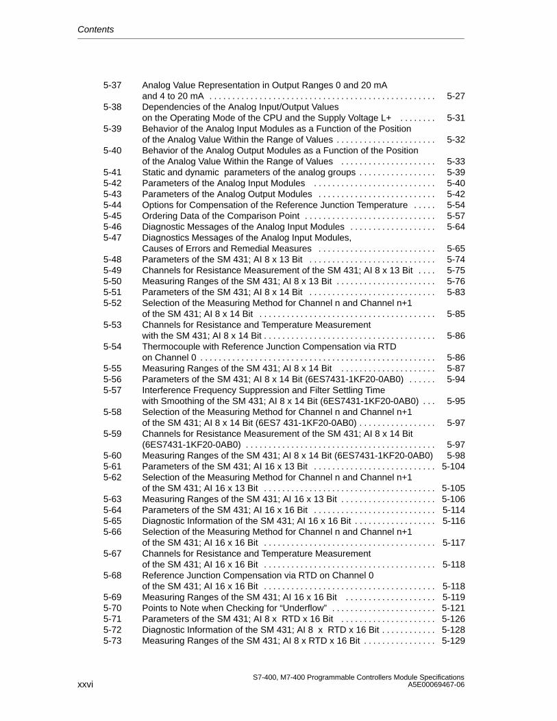
5-37 Analog Value Representation in Output Ranges 0 and 20 mA and 4 to 20 mA 5-27. . . . . . . . . . . . . . . . . . . . . . . . . . . . . . . . . . . . . . . . . . . . . . . . . .
5-38 Dependencies of the Analog Input/Output Values on the Operating Mode of the CPU and the Supply Voltage L+ 5-31. . . . . . . .
5-39 Behavior of the Analog Input Modules as a Function of the Position of the Analog Value Within the Range of Values 5-32. . . . . . . . . . . . . . . . . . . . . .
5-40 Behavior of the Analog Output Modules as a Function of the Position of the Analog Value Within the Range of Values 5-33. . . . . . . . . . . . . . . . . . . . .
5-41 Static and dynamic parameters of the analog groups 5-39. . . . . . . . . . . . . . . . . 5-42 Parameters of the Analog Input Modules 5-40. . . . . . . . . . . . . . . . . . . . . . . . . . . 5-43 Parameters of the Analog Output Modules 5-42. . . . . . . . . . . . . . . . . . . . . . . . . . 5-44 Options for Compensation of the Reference Junction Temperature 5-54. . . . . 5-45 Ordering Data of the Comparison Point 5-57. . . . . . . . . . . . . . . . . . . . . . . . . . . . . 5-46 Diagnostic Messages of the Analog Input Modules 5-64. . . . . . . . . . . . . . . . . . . 5-47 Diagnostics Messages of the Analog Input Modules,
Causes of Errors and Remedial Measures 5-65. . . . . . . . . . . . . . . . . . . . . . . . . . 5-48 Parameters of the SM 431; AI 8 x 13 Bit 5-74. . . . . . . . . . . . . . . . . . . . . . . . . . . . 5-49 Channels for Resistance Measurement of the SM 431; AI 8 x 13 Bit 5-75. . . . 5-50 Measuring Ranges of the SM 431; AI 8 x 13 Bit 5-76. . . . . . . . . . . . . . . . . . . . . . 5-51 Parameters of the SM 431; AI 8 x 14 Bit 5-83. . . . . . . . . . . . . . . . . . . . . . . . . . . . 5-52 Selection of the Measuring Method for Channel n and Channel n+1
of the SM 431; AI 8 x 14 Bit 5-85. . . . . . . . . . . . . . . . . . . . . . . . . . . . . . . . . . . . . . . 5-53 Channels for Resistance and Temperature Measurement
with the SM 431; AI 8 x 14 Bit 5-86. . . . . . . . . . . . . . . . . . . . . . . . . . . . . . . . . . . . . . 5-54 Thermocouple with Reference Junction Compensation via RTD
on Channel 0 5-86. . . . . . . . . . . . . . . . . . . . . . . . . . . . . . . . . . . . . . . . . . . . . . . . . . . . 5-55 Measuring Ranges of the SM 431; AI 8 x 14 Bit 5-87. . . . . . . . . . . . . . . . . . . . . 5-56 Parameters of the SM 431; AI 8 x 14 Bit (6ES7431-1KF20-0AB0) 5-94. . . . . . 5-57 Interference Frequency Suppression and Filter Settling Time
with Smoothing of the SM 431; AI 8 x 14 Bit (6ES7431-1KF20-0AB0) 5-95. . . 5-58 Selection of the Measuring Method for Channel n and Channel n+1
of the SM 431; AI 8 x 14 Bit (6ES7 431-1KF20-0AB0) 5-97. . . . . . . . . . . . . . . . . 5-59 Channels for Resistance Measurement of the SM 431; AI 8 x 14 Bit
(6ES7431-1KF20-0AB0) 5-97. . . . . . . . . . . . . . . . . . . . . . . . . . . . . . . . . . . . . . . . . . 5-60 Measuring Ranges of the SM 431; AI 8 x 14 Bit (6ES7431-1KF20-0AB0) 5-985-61 Parameters of the SM 431; AI 16 x 13 Bit 5-104. . . . . . . . . . . . . . . . . . . . . . . . . . . 5-62 Selection of the Measuring Method for Channel n and Channel n+1
of the SM 431; AI 16 x 13 Bit 5-105. . . . . . . . . . . . . . . . . . . . . . . . . . . . . . . . . . . . . . 5-63 Measuring Ranges of the SM 431; AI 16 x 13 Bit 5-106. . . . . . . . . . . . . . . . . . . . . 5-64 Parameters of the SM 431; AI 16 x 16 Bit 5-114. . . . . . . . . . . . . . . . . . . . . . . . . . . 5-65 Diagnostic Information of the SM 431; AI 16 x 16 Bit 5-116. . . . . . . . . . . . . . . . . . 5-66 Selection of the Measuring Method for Channel n and Channel n+1
of the SM 431; AI 16 x 16 Bit 5-117. . . . . . . . . . . . . . . . . . . . . . . . . . . . . . . . . . . . . . 5-67 Channels for Resistance and Temperature Measurement
of the SM 431; AI 16 x 16 Bit 5-118. . . . . . . . . . . . . . . . . . . . . . . . . . . . . . . . . . . . . . 5-68 Reference Junction Compensation via RTD on Channel 0
of the SM 431; AI 16 x 16 Bit 5-118. . . . . . . . . . . . . . . . . . . . . . . . . . . . . . . . . . . . . . 5-69 Measuring Ranges of the SM 431; AI 16 x 16 Bit 5-119. . . . . . . . . . . . . . . . . . . . 5-70 Points to Note when Checking for “Underflow” 5-121. . . . . . . . . . . . . . . . . . . . . . . 5-71 Parameters of the SM 431; AI 8 x RTD x 16 Bit 5-126. . . . . . . . . . . . . . . . . . . . . 5-72 Diagnostic Information of the SM 431; AI 8 x RTD x 16 Bit 5-128. . . . . . . . . . . . 5-73 Measuring Ranges of the SM 431; AI 8 x RTD x 16 Bit 5-129. . . . . . . . . . . . . . . .
Contents
xxviiS7-400, M7-400 Programmable Controllers Module SpecificationsA5E00069467-06
5-74 Parameters of the SM 431; AI 8 x 16 Bit 5-135. . . . . . . . . . . . . . . . . . . . . . . . . . . . 5-75 How Response Times Depend on the
Parameterized Interference Frequency Suppression and Smoothing of the SM 431; AI 8 x 16 Bit 5-136. . . . . . . . . . . . . . . . . . . . . . . . .
5-76 Diagnostic Information of the SM 431; AI 8 x 16 Bit 5-139. . . . . . . . . . . . . . . . . . . 5-77 Measuring Ranges of the SM 431; AI 8 x 16 Bit 5-140. . . . . . . . . . . . . . . . . . . . . . 5-78 Output Ranges of the Analog Output Module SM 432; AO8 x 13 Bit 5-145. . . . 6-1 Interface Modules of the S7-400 6-2. . . . . . . . . . . . . . . . . . . . . . . . . . . . . . . . . . . 6-2 Terminators for the Receive IMs 6-4. . . . . . . . . . . . . . . . . . . . . . . . . . . . . . . . . . . . 6-3 Connecting Cable for Interface Modules 6-5. . . . . . . . . . . . . . . . . . . . . . . . . . . . 7-1 S5 Interface Modules 7-2. . . . . . . . . . . . . . . . . . . . . . . . . . . . . . . . . . . . . . . . . . . . . 7-2 LEDs of the IM 4632 7-5. . . . . . . . . . . . . . . . . . . . . . . . . . . . . . . . . . . . . . . . . . . . . . 7-3 LEDs of the IM 463-2 7-5. . . . . . . . . . . . . . . . . . . . . . . . . . . . . . . . . . . . . . . . . . . . . 7-4 Switch Position: Interface Selector of the IM 463-2 7-5. . . . . . . . . . . . . . . . . . . 7-5 Settings Address Areas on the IM 314 7-9. . . . . . . . . . . . . . . . . . . . . . . . . . . . . . 7-6 Assignment of the Connecting Cable 721 7-11. . . . . . . . . . . . . . . . . . . . . . . . . . . 7-7 Assignment of the Terminator 760-1AA11 7-13. . . . . . . . . . . . . . . . . . . . . . . . . . . 8-1 Operating Modes of the IM 467/467 FO 8-4. . . . . . . . . . . . . . . . . . . . . . . . . . . . . 8-2 CPU and IM 467/467 FO 8-7. . . . . . . . . . . . . . . . . . . . . . . . . . . . . . . . . . . . . . . . . . 9-1 Function of Fan Monitoring 9-2. . . . . . . . . . . . . . . . . . . . . . . . . . . . . . . . . . . . . . . . 10-1 Maximum Cable Length of a Segment 10-2. . . . . . . . . . . . . . . . . . . . . . . . . . . . . . 10-2 Maximum Cable Length between Two RS 485 Repeaters 10-2. . . . . . . . . . . . . 10-3 Description and Functions of the RS 485 Repeater 10-3. . . . . . . . . . . . . . . . . . . 11-1 Performance Features of the CPUs 11-2. . . . . . . . . . . . . . . . . . . . . . . . . . . . . . . . . 11-2 Technical Specifications of the CPUs 11-3. . . . . . . . . . . . . . . . . . . . . . . . . . . . . . . 11-3 Elements of the CPU 486-3 and CPU 488-3 11-5. . . . . . . . . . . . . . . . . . . . . . . . . 11-4 Meaning of the Status and Fault LEDs on the CPU 486-3 and CPU 488-3 11-711-5 Positions of the Mode Selector Switch 11-9. . . . . . . . . . . . . . . . . . . . . . . . . . . . . . 11-6 Main Memory Expansion Possibilities 11-13. . . . . . . . . . . . . . . . . . . . . . . . . . . . . . 11-7 BIOS Hot Keys with German and English Key Assignments 11-19. . . . . . . . . . . 11-8 Main Memory Assignment 11-41. . . . . . . . . . . . . . . . . . . . . . . . . . . . . . . . . . . . . . . . . 11-9 Interrupt Assignment 11-43. . . . . . . . . . . . . . . . . . . . . . . . . . . . . . . . . . . . . . . . . . . . . 12-1 Expansion Possibilities of the CPU 486-3, CPU 488-3, or FM 456 12-5. . . . . . 12-2 Division of Addresses Within an Expansion Module 12-11. . . . . . . . . . . . . . . . . . . 12-3 Base Addresses of the Interface Submodules with FM 456-4 12-12. . . . . . . . . . 12-4 Base Addresses of the Expansion Modules with CPU 486-3, CPU 488-3 12-1212-5 Pin Assignments of the 98-Pin Standard Direct Connector
(ATConnector) 12-17. . . . . . . . . . . . . . . . . . . . . . . . . . . . . . . . . . . . . . . . . . . . . . . . . . 12-6 Calculation Example for Total Power Losses of an ATM 478
with AT Module 12-20. . . . . . . . . . . . . . . . . . . . . . . . . . . . . . . . . . . . . . . . . . . . . . . . . . 12-7 MSM 478 Parallel Port, Socket X1 (25-Pin Sub D Socket) 12-24. . . . . . . . . . . . 13-1 Format of the Interrupt Entry in the BIOS Setup
of the Interface Submodule 13-3. . . . . . . . . . . . . . . . . . . . . . . . . . . . . . . . . . . . . . . . 13-2 Overview of the Submodule IDs for the Interface Submodules 13-4. . . . . . . . . 13-3 Insertion Rules for Interface Submodules
that Cannot be Used in All Receptacles 13-4. . . . . . . . . . . . . . . . . . . . . . . . . . . . . 13-4 Socket X1, VGA Screen Connection IF 962-VGA
(15-Pin High-Density Sub D Socket Connector) 13-6. . . . . . . . . . . . . . . . . . . . . . 13-5 X2 Socket, Keyboard Plug Connection IF 961-VGA
(6-Pin Mini DIN Socket Connector) 13-6. . . . . . . . . . . . . . . . . . . . . . . . . . . . . . . . . 13-6 Interrupt Assignments of the IF 962-VGA Interface Submodule 13-7. . . . . . . . . 13-7 Video Modes of the IF 962-VGA Interface Submodule 13-9. . . . . . . . . . . . . . . .
Contents
xxviiiS7-400, M7-400 Programmable Controllers Module Specifications
A5E00069467-06
13-8 Socket X1, X2 IF 962-COM (9-Pin Sub D Plug Connector) 13-11. . . . . . . . . . . . 13-9 Addressing the COM Ports in the AT-Compatible Address Area 13-12. . . . . . . . 13-10 Offset Address Assignments for the IF 962-COM Interface Submodule 13-13. . 13-11 Offset Address for the Configuration Register (IF 962-COM) 13-13. . . . . . . . . . . 13-12 Meaning of the Data Bits in the Configuration Register (IF 962-COM) 13-13. . . 13-13 Meaning of the Addressing Type Bits in the Configuration Register
(IF 962-COM) 13-14. . . . . . . . . . . . . . . . . . . . . . . . . . . . . . . . . . . . . . . . . . . . . . . . . . . 13-14 Interrupt Assignments of the IF 962-COM Interface Submodule 13-15. . . . . . . . 13-15 Socket X1, IF 962-LPT (25-Pin Sub D Socket Connector) 13-17. . . . . . . . . . . . . 13-16 Addressing the LPT Ports 13-18. . . . . . . . . . . . . . . . . . . . . . . . . . . . . . . . . . . . . . . . . 13-17 Offset Address Assignments for the IF 962-LPT Interface Submodule 13-19. . . 13-18 Offset Address for the Configuration Register (IF 962-LPT) 13-20. . . . . . . . . . . . 13-19 Meaning of the Data Bits in the Configuration Register (IF 962-LPT) 13-20. . . . 13-20 Meaning of the Addressing Type Bits in the
Configuration Register (IF 962-LPT) 13-21. . . . . . . . . . . . . . . . . . . . . . . . . . . . . . . 13-21 Offset Address Assignments for the IF 961-DIO Interface Submodule 13-26. . . 13-22 Offset Address for the Digital Input Function (IF 961-DIO) 13-26. . . . . . . . . . . . . 13-23 Assignment of the Digital Input (DI) Channels to the Bits (IF 961-DIO) 13-26. . 13-24 Offset Address for the Digital Output Function (IF 961-DIO) 13-27. . . . . . . . . . . . 13-25 Assignment of the Digital Output (DO) Channels to the Bits (IF 961-DIO) 13-2713-26 Offset Address for the Acknowledgment Register (IF 961-DIO) 13-27. . . . . . . . . 13-27 Meaning of the Bits in the Acknowledgment Register (IF 961-DIO) 13-27. . . . . . 13-28 Offset Address for the Interrupt Register (IF 961-DIO) 13-28. . . . . . . . . . . . . . . . 13-29 Meaning of the Bits in the Interrupt Register (IF 961-DIO) 13-28. . . . . . . . . . . . . 13-30 Offset Address for the Interrupt Enable Register (IF 961-DIO) 13-28. . . . . . . . . . 13-31 Meaning of the Bits in the Interrupt Enable Register (IF 961-DIO) 13-28. . . . . . . 13-32 Offset Address for the Selection Register Rising Edge (IF 961-DIO) 13-29. . . . 13-33 Meaning of the Bits in the Selection Register Rising Edge (IF 961-DIO) 13-29. 13-34 Offset Address for the Selection Register Falling Edge (IF 961-DIO) 13-29. . . . 13-35 Meaning of the Bits in the Selection Register Falling Edge (IF 961-DIO) 13-29. 13-36 Offset Address for the Mode Register (IF 961-DIO) 13-30. . . . . . . . . . . . . . . . . . . 13-37 Meaning of the Bits in the Mode Register (IF 961-DIO) 13-30. . . . . . . . . . . . . . . . 13-38 Meaning of the Signals of the X1 Socket
of the IF 961-AIO Interface Submodule 13-35. . . . . . . . . . . . . . . . . . . . . . . . . . . . . 13-39 Offset Address Assignments for the IF 961-AIO Interface Submodule 13-46. . . 13-40 Meaning of the Data Bits in the Analog Output Function (IF 961-AIO) 13-47. . . 13-41 Meaning of the Input Bits in the Analog Input Function (IF 961-AIO) 13-48. . . . 13-42 Meaning of the Control Bits in the Analog Input Function (IF 961-AIO) 13-49. . 13-43 Representation of the Digitized Measured Value
for the Analog Input Function (Voltage and Current Measuring Range) 13-51. . 13-44 Representation of the Analog Output Ranges
(Voltage and Current Output Ranges) 13-52. . . . . . . . . . . . . . . . . . . . . . . . . . . . . . . 13-45 X1 Socket, IF 964-DP (9-Pin Sub D Connector) 13-63. . . . . . . . . . . . . . . . . . . . . . A-1 SFCs for assigning Parameters to Signal Modules A-2. . . . . . . . . . . . . . . . . . . A-2 Parameters of the Digital Input Modules A-4. . . . . . . . . . . . . . . . . . . . . . . . . . . . A-3 Parameters of the Digital Output Modules A-7. . . . . . . . . . . . . . . . . . . . . . . . . . A-4 Parameters of the Analog Input Modules A-10. . . . . . . . . . . . . . . . . . . . . . . . . . . B-1 Codes of the Module Types B-3. . . . . . . . . . . . . . . . . . . . . . . . . . . . . . . . . . . . . . .
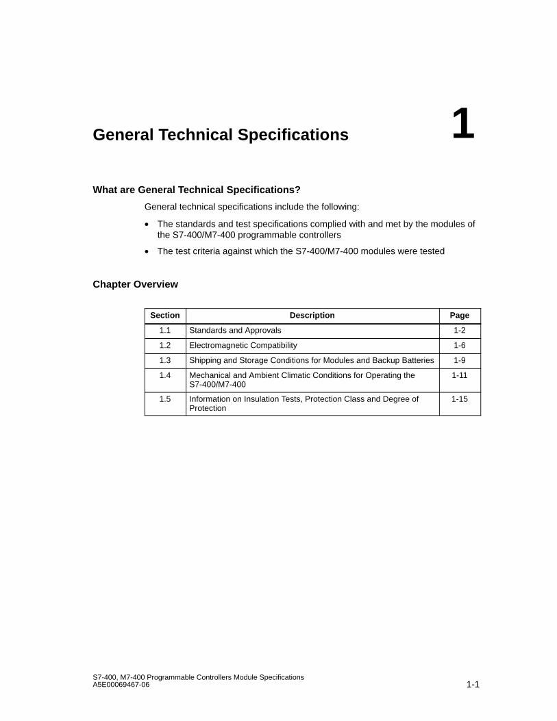
1-1S7-400, M7-400 Programmable Controllers Module SpecificationsA5E00069467-06
General Technical Specifications
What are General Technical Specifications?
General technical specifications include the following:
• The standards and test specifications complied with and met by the modules ofthe S7-400/M7-400 programmable controllers
• The test criteria against which the S7-400/M7-400 modules were tested
Chapter Overview
Section Description Page
1.1 Standards and Approvals 1-2
1.2 Electromagnetic Compatibility 1-6
1.3 Shipping and Storage Conditions for Modules and Backup Batteries 1-9
1.4 Mechanical and Ambient Climatic Conditions for Operating theS7-400/M7-400
1-11
1.5 Information on Insulation Tests, Protection Class and Degree ofProtection
1-15
1
General Technical Specifications
1-2S7-400, M7-400 Programmable Controllers Module Specifications
A5E00069467-06
1.1 Standards and Approvals
IEC 61131-2
The S7-400/M7-400 programmable controller satisfies the requirements andcriteria of the IEC 61131-2 standard.
CE Mark
Our products satisfy the requirements and protection objectives of the ECDirectives listed below and comply with the harmonized European standards (EN) promulgated in the Official Journals of the European Community forprogrammable controllers:
• 73/23/EEC “Electrical Equipment Designed for Use between Certain VoltageLimits” (Low-Voltage Directive)
• 89/336/EEC “Electromagnetic Compatibility” (EMC Directive)
The declarations of conformity are held at the disposal of the competent authoritiesat the address below:
Siemens AktiengesellschaftBereich Automation and Drives A&D AS RD 42Postfach 1963D-92209 Amberg
EMC Directive
SIMATIC products have been designed for use in industrial environments.
Table 1-1 Use in an Industrial Environment
EMC Directive Requirements in respect of:
Emitted interference Immunity
Industry EN 50081-2 : 1993 EN 61000-6-2 : 1999
General Technical Specifications
1-3S7-400, M7-400 Programmable Controllers Module SpecificationsA5E00069467-06
Low Voltage Directive
The products listed in the table below fulfill the requirements of EU low-voltagedirective (73/23/EEC). Adherence to this EU directive was tested in accordancewith IEC 61131-2.
Table 1-2 Products that Fulfill the Requirements of the Low-Voltage Directive
Name Order number
Digital Input Module SM 421; DI 32 x 120 VUC 6ES7421-1EL00-0AA0
Digital Input Module SM 421; DI 16 x 120/230 VUC 6ES7421-1FH00-0AA0
Digital Output Module SM 422; DO 8 x 120/230 VAC/5 A 6ES7422-1FF00-0AA0
Digital Output Module SM 422; DO 16 x 120/230 VAC/2 A 6ES7422-1FH00-0AB0
Relay Output Module SM 422; DO 16 x 30/230 VUC/Rel5A 6ES7422-1HH00-0AA0
The 120/230 VAC Fan Subassembly 6ES7408-1TB00-0XA0
PS 407 4A 6ES7407-0DA00-0AA0
6ES7407-0DA01-0AA0
PS 407 10A 6ES7407-0KA00-0AA0
6ES7407-0KA01-0AA0
PS 407 20A 6ES7407-0RA00-0AA06ES7407-0RA01-0AA0
PS 407 10AR 6ES7407-0KR00-0AA0
Mark for Australia and New Zealand
Our products satisfy the requirements of Standard AS/NZS 2064 (Class A).
UL Approval
UL recognition markUnderwriters Laboratories (UL) to the UL 508 Standard:
• Report E 85972
• Report 143289 for the modules in Table 1-3
CSA Approval
CSA certification markCanadian Standard Association (CSA) to Standard C 22. No. 142:
• Certification Record 212191-0-000
• Report 111 879 for the modules in Table 1-3
General Technical Specifications
1-4S7-400, M7-400 Programmable Controllers Module Specifications
A5E00069467-06
FM Approval
Factory Mutual Approval Standard Class Number 3611, Class I, Division 2, GroupA, B, C, D.
Temperature class: T4 at 60 °C ambient temperature
Exception:
The following applies to the power supply modules in Table 1-3:
• Temperature class T3C at 60 °C ambient temperature
• Temperature class T4 at 40 °C ambient temperature
In the case of the modules in Table 1-3 the T4 temperature class is achieved forthe whole system if the ambient temperature does not exceed 40 °C duringoperation. There are also certain additional requirements that you can complywith by installing the system in cabinets.
Table 1-3 Power Supply Modules
Name Order number
PS 407 4 A Power Supply Module 6ES7 407-0DA00-0AA0
PS 407 10 A Power Supply Module 6ES7 407-0KA00-0AA0
PS 407 20 A Power Supply Module 6ES7 407-0RA00-0AA0
PS 405 4 A Power Supply Module 6ES7 405-0DA00-0AA0
PS 405 10 A Power Supply Module 6ES7 405-0KA00-0AA0
PS 405 20 A Power Supply Module 6ES7 405-0RA00-0AA0
!Warning
Personal injury or property damage can result.
In hazardous areas, personal injury or property damage can result if you create orbreak an electrical circuit during operation of an S7-400/M7-400 (for example, bymeans of plug-in connections, fuses, switches).
Do not create or break live electric circuits unless you are certain there is nodanger of explosion.
General Technical Specifications
1-5S7-400, M7-400 Programmable Controllers Module SpecificationsA5E00069467-06
Safety Requirements for Installation
The S7-400/M7-400 programmable controllers are “open type” equipment to theIEC 61131-2 standard and therefore adhere to the EU directive 73/23/EEC“Low-Voltage Directive” and are UL/CSA certified as such.
To fulfill requirements for safe operation with regard to mechanical stability, flameretardance, stability, and shock-hazard protection, the following alternative types ofinstallation are specified:
• Installation in a suitable cabinet
• Installation in a suitable housing
• Installation in a suitably equipped, enclosed operating area.
General Technical Specifications
1-6S7-400, M7-400 Programmable Controllers Module Specifications
A5E00069467-06
1.2 Electromagnetic Compatibility
Introduction
In this section you will find information on the noise immunity of S7-400/M7-400modules and on radio interference suppression.
All the components of S7-400/M7-400 systems meet the requirements of thestandards that apply in Europe provided they are installed in accordance with allthe appropriate regulations (see Installation Manual, Chapters 2 and 4).
Definition of “EMC”
Electromagnetic compatibility (EMC) is the ability of an electrical installation tofunction satisfactorily in its electromagnetic environment without interfering withthat environment.
!Warning
Personal injury or property damage can result.
Installation of expansions that have not been approved for the S7-400/M7-400 canresult in violations of the requirements and regulations for safety andelectromagnetic compatibility.
Use only expansions that have been approved for the system.
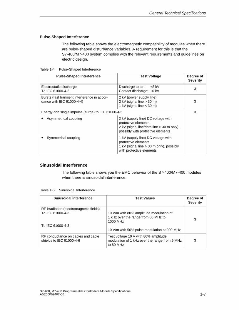
General Technical Specifications
1-7S7-400, M7-400 Programmable Controllers Module SpecificationsA5E00069467-06
Pulse-Shaped Interference
The following table shows the electromagnetic compatibility of modules when thereare pulse-shaped disturbance variables. A requirement for this is that theS7-400/M7-400 system complies with the relevant requirements and guidelines onelectric design.
Table 1-4 Pulse-Shaped Interference
Pulse-Shaped Interference Test Voltage Degree ofSeverity
Electrostatic dischargeTo IEC 61000-4-2
Discharge to air: ±8 kVContact discharge: ±6 kV
3
Bursts (fast transient interference in accor-dance with IEC 61000-4-4)
2 kV (power supply line)2 kV (signal line > 30 m)1 kV (signal line < 30 m)
3
Energy-rich single impulse (surge) to IEC 61000-4-5 3
• Asymmetrical coupling 2 kV (supply line) DC voltage withprotective elements2 kV (signal line/data line > 30 m only),possibly with protective elements
• Symmetrical coupling 1 kV (supply line) DC voltage withprotective elements1 kV (signal line > 30 m only), possiblywith protective elements
Sinusoidal Interference
The following table shows you the EMC behavior of the S7-400/M7-400 moduleswhen there is sinusoidal interference.
Table 1-5 Sinusoidal Interference
Sinusoidal Interference Test Values Degree ofSeverity
RF irradiation (electromagnetic fields)To IEC 61000-4-3
To IEC 61000-4-3
10 V/m with 80% amplitude modulation of1 kHz over the range from 80 MHz to1000 MHz
10 V/m with 50% pulse modulation at 900 MHz
3
RF conductance on cables and cableshields to IEC 61000-4-6
Test voltage 10 V with 80% amplitudemodulation of 1 kHz over the range from 9 MHzto 80 MHz
3
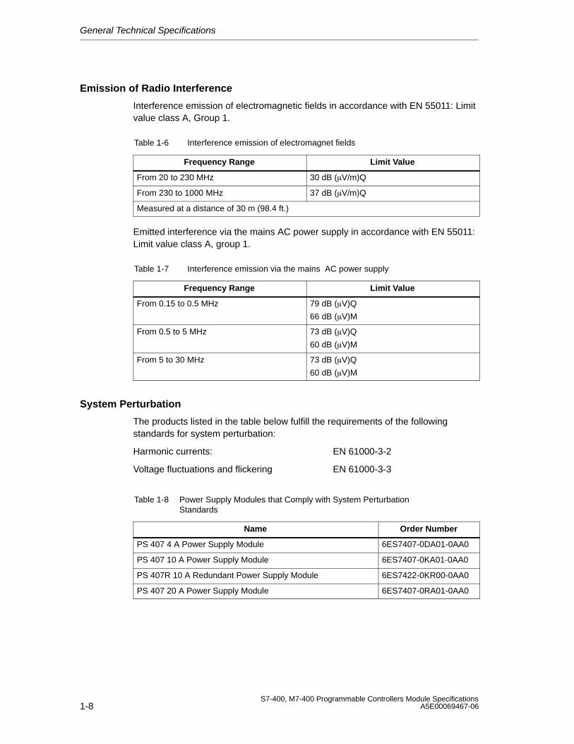
General Technical Specifications
1-8S7-400, M7-400 Programmable Controllers Module Specifications
A5E00069467-06
Emission of Radio Interference
Interference emission of electromagnetic fields in accordance with EN 55011: Limitvalue class A, Group 1.
Table 1-6 Interference emission of electromagnet fields
Frequency Range Limit Value
From 20 to 230 MHz 30 dB (V/m)Q
From 230 to 1000 MHz 37 dB (V/m)Q
Measured at a distance of 30 m (98.4 ft.)
Emitted interference via the mains AC power supply in accordance with EN 55011:Limit value class A, group 1.
Table 1-7 Interference emission via the mains AC power supply
Frequency Range Limit Value
From 0.15 to 0.5 MHz 79 dB (V)Q
66 dB (V)M
From 0.5 to 5 MHz 73 dB (V)Q
60 dB (V)M
From 5 to 30 MHz 73 dB (V)Q
60 dB (V)M
System Perturbation
The products listed in the table below fulfill the requirements of the followingstandards for system perturbation:
Harmonic currents: EN 61000-3-2
Voltage fluctuations and flickering EN 61000-3-3
Table 1-8 Power Supply Modules that Comply with System PerturbationStandards
Name Order Number
PS 407 4 A Power Supply Module 6ES7407-0DA01-0AA0
PS 407 10 A Power Supply Module 6ES7407-0KA01-0AA0
PS 407R 10 A Redundant Power Supply Module 6ES7422-0KR00-0AA0
PS 407 20 A Power Supply Module 6ES7407-0RA01-0AA0
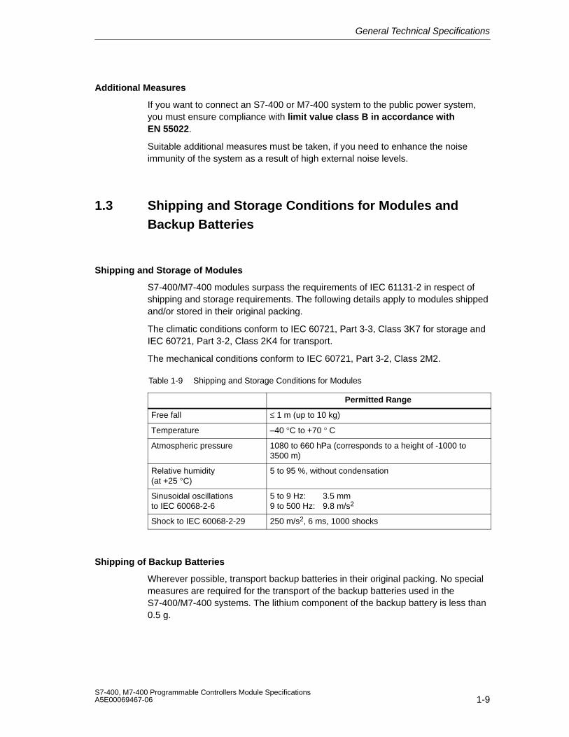
General Technical Specifications
1-9S7-400, M7-400 Programmable Controllers Module SpecificationsA5E00069467-06
Additional Measures
If you want to connect an S7-400 or M7-400 system to the public power system,you must ensure compliance with limit value class B in accordance withEN 55022.
Suitable additional measures must be taken, if you need to enhance the noiseimmunity of the system as a result of high external noise levels.
1.3 Shipping and Storage Conditions for Modules andBackup Batteries
Shipping and Storage of Modules
S7-400/M7-400 modules surpass the requirements of IEC 61131-2 in respect ofshipping and storage requirements. The following details apply to modules shippedand/or stored in their original packing.
The climatic conditions conform to IEC 60721, Part 3-3, Class 3K7 for storage andIEC 60721, Part 3-2, Class 2K4 for transport.
The mechanical conditions conform to IEC 60721, Part 3-2, Class 2M2.
Table 1-9 Shipping and Storage Conditions for Modules
Permitted Range
Free fall ≤ 1 m (up to 10 kg)
Temperature –40 °C to +70 ° C
Atmospheric pressure 1080 to 660 hPa (corresponds to a height of -1000 to3500 m)
Relative humidity (at +25 °C)
5 to 95 %, without condensation
Sinusoidal oscillationsto IEC 60068-2-6
5 to 9 Hz: 3.5 mm9 to 500 Hz: 9.8 m/s2
Shock to IEC 60068-2-29 250 m/s2, 6 ms, 1000 shocks
Shipping of Backup Batteries
Wherever possible, transport backup batteries in their original packing. No specialmeasures are required for the transport of the backup batteries used in theS7-400/M7-400 systems. The lithium component of the backup battery is less than0.5 g.
General Technical Specifications
1-10S7-400, M7-400 Programmable Controllers Module Specifications
A5E00069467-06
Storing Backup Batteries
Backup batteries must be stored in a cool, dry place. The maximum storage time is10 years.
!WarningImproper handling of backup batteries can cause injury and material damage. Ifbackup batteries are not treated properly, they can explode and cause severeburning.Please observe the following rules when handling backup batteries used in theS7-400/M7-400 programmable controllers:
• never charge them• never heat them• never throw them in the fire• never damage them mechanically (drill, squeeze, etc.)
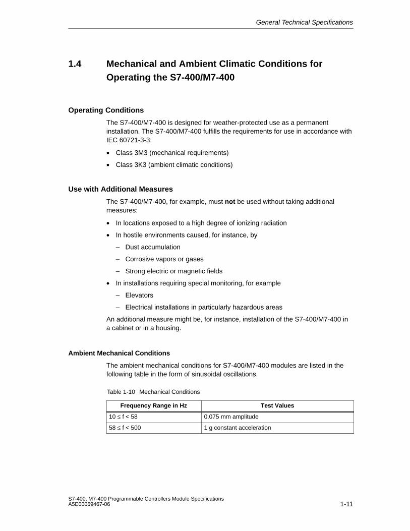
General Technical Specifications
1-11S7-400, M7-400 Programmable Controllers Module SpecificationsA5E00069467-06
1.4 Mechanical and Ambient Climatic Conditions forOperating the S7-400/M7-400
Operating Conditions
The S7-400/M7-400 is designed for weather-protected use as a permanentinstallation. The S7-400/M7-400 fulfills the requirements for use in accordance withIEC 60721-3-3:
• Class 3M3 (mechanical requirements)
• Class 3K3 (ambient climatic conditions)
Use with Additional Measures
The S7-400/M7-400, for example, must not be used without taking additionalmeasures:
• In locations exposed to a high degree of ionizing radiation
• In hostile environments caused, for instance, by
– Dust accumulation
– Corrosive vapors or gases
– Strong electric or magnetic fields
• In installations requiring special monitoring, for example
– Elevators
– Electrical installations in particularly hazardous areas
An additional measure might be, for instance, installation of the S7-400/M7-400 ina cabinet or in a housing.
Ambient Mechanical Conditions
The ambient mechanical conditions for S7-400/M7-400 modules are listed in thefollowing table in the form of sinusoidal oscillations.
Table 1-10 Mechanical Conditions
Frequency Range in Hz Test Values
10 ≤ f < 58 0.075 mm amplitude
58 ≤ f < 500 1 g constant acceleration
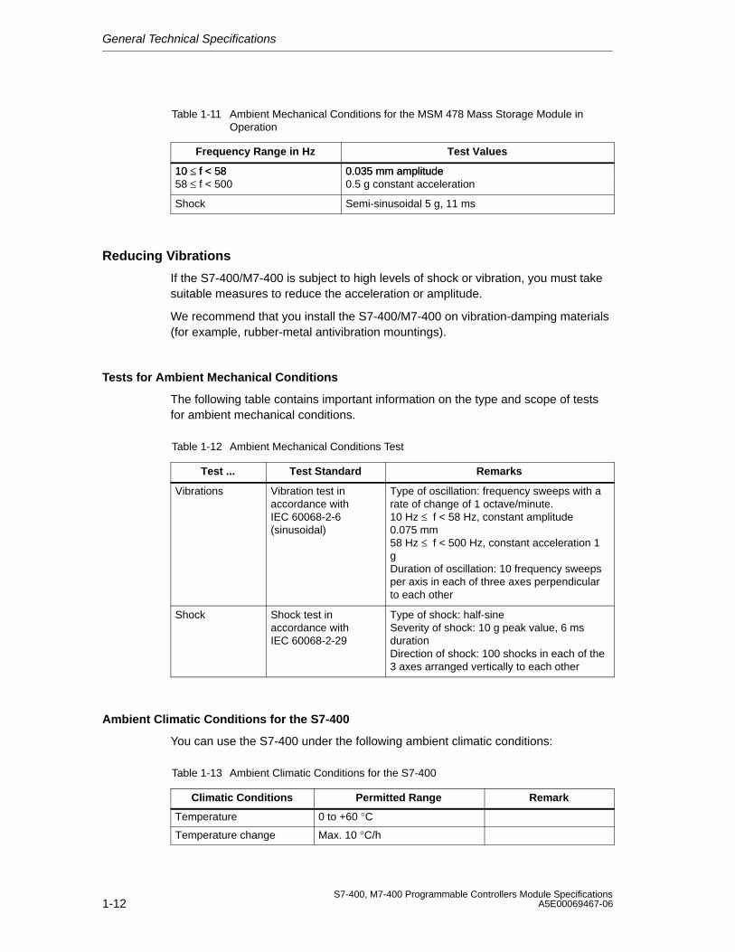
General Technical Specifications
1-12S7-400, M7-400 Programmable Controllers Module Specifications
A5E00069467-06
Table 1-11 Ambient Mechanical Conditions for the MSM 478 Mass Storage Module inOperation
Frequency Range in Hz Test Values
10 ≤ f < 58 0.035 mm amplitude10 ≤ f < 5858 ≤ f < 500
0.035 mm amplitude0.5 g constant acceleration
Shock Semi-sinusoidal 5 g, 11 ms
Reducing Vibrations
If the S7-400/M7-400 is subject to high levels of shock or vibration, you must takesuitable measures to reduce the acceleration or amplitude.
We recommend that you install the S7-400/M7-400 on vibration-damping materials(for example, rubber-metal antivibration mountings).
Tests for Ambient Mechanical Conditions
The following table contains important information on the type and scope of testsfor ambient mechanical conditions.
Table 1-12 Ambient Mechanical Conditions Test
Test ... Test Standard Remarks
Vibrations Vibration test inaccordance withIEC 60068-2-6(sinusoidal)
Type of oscillation: frequency sweeps with arate of change of 1 octave/minute.10 Hz ≤ f < 58 Hz, constant amplitude0.075 mm58 Hz ≤ f < 500 Hz, constant acceleration 1gDuration of oscillation: 10 frequency sweepsper axis in each of three axes perpendicularto each other
Shock Shock test inaccordance withIEC 60068-2-29
Type of shock: half-sineSeverity of shock: 10 g peak value, 6 msdurationDirection of shock: 100 shocks in each of the3 axes arranged vertically to each other
Ambient Climatic Conditions for the S7-400
You can use the S7-400 under the following ambient climatic conditions:
Table 1-13 Ambient Climatic Conditions for the S7-400
Climatic Conditions Permitted Range Remark
Temperature 0 to +60 °C
Temperature change Max. 10 °C/h
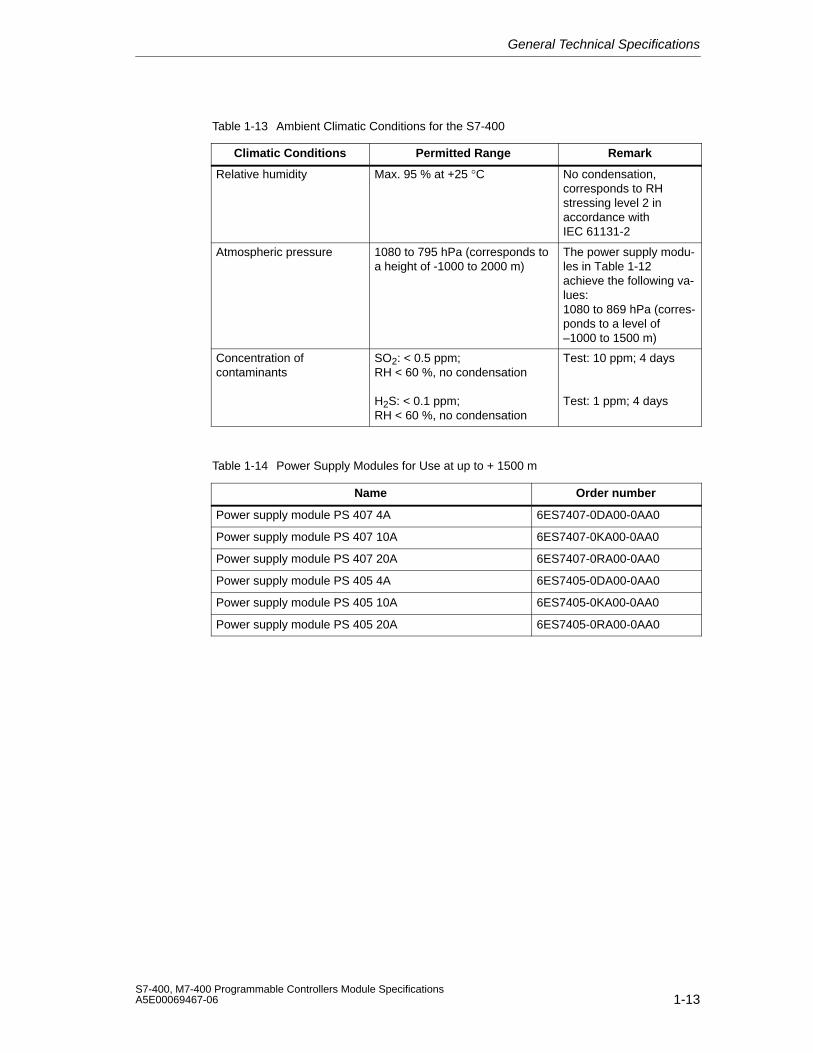
General Technical Specifications
1-13S7-400, M7-400 Programmable Controllers Module SpecificationsA5E00069467-06
Table 1-13 Ambient Climatic Conditions for the S7-400
Climatic Conditions RemarkPermitted Range
Relative humidity Max. 95 % at +25 °C No condensation,corresponds to RHstressing level 2 inaccordance withIEC 61131-2
Atmospheric pressure 1080 to 795 hPa (corresponds toa height of -1000 to 2000 m)
The power supply modu-les in Table 1-12achieve the following va-lues:1080 to 869 hPa (corres-ponds to a level of–1000 to 1500 m)
Concentration ofcontaminants
SO2: < 0.5 ppm;RH < 60 %, no condensation
H2S: < 0.1 ppm;RH < 60 %, no condensation
Test: 10 ppm; 4 days
Test: 1 ppm; 4 days
Table 1-14 Power Supply Modules for Use at up to + 1500 m
Name Order number
Power supply module PS 407 4A 6ES7407-0DA00-0AA0
Power supply module PS 407 10A 6ES7407-0KA00-0AA0
Power supply module PS 407 20A 6ES7407-0RA00-0AA0
Power supply module PS 405 4A 6ES7405-0DA00-0AA0
Power supply module PS 405 10A 6ES7405-0KA00-0AA0
Power supply module PS 405 20A 6ES7405-0RA00-0AA0
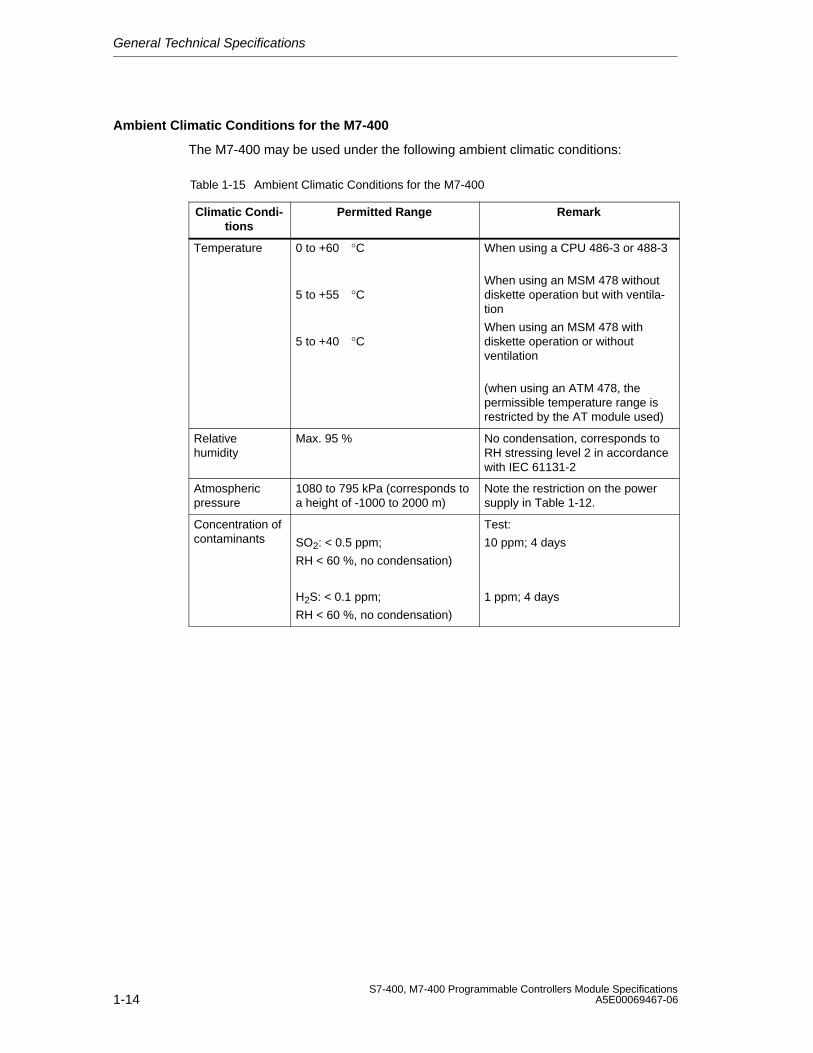
General Technical Specifications
1-14S7-400, M7-400 Programmable Controllers Module Specifications
A5E00069467-06
Ambient Climatic Conditions for the M7-400
The M7-400 may be used under the following ambient climatic conditions:
Table 1-15 Ambient Climatic Conditions for the M7-400
Climatic Condi-tions
Permitted Range Remark
Temperature 0 to +60°C 5 to +55°C
5 to +40°C
When using a CPU 486-3 or 488-3
When using an MSM 478 withoutdiskette operation but with ventila-tion
When using an MSM 478 withdiskette operation or withoutventilation
(when using an ATM 478, thepermissible temperature range isrestricted by the AT module used)
Relativehumidity
Max. 95 % No condensation, corresponds toRH stressing level 2 in accordancewith IEC 61131-2
Atmosphericpressure
1080 to 795 kPa (corresponds toa height of -1000 to 2000 m)
Note the restriction on the powersupply in Table 1-12.
Concentration ofcontaminants SO2: < 0.5 ppm;
RH < 60 %, no condensation)
H2S: < 0.1 ppm;
RH < 60 %, no condensation)
Test:
10 ppm; 4 days
1 ppm; 4 days
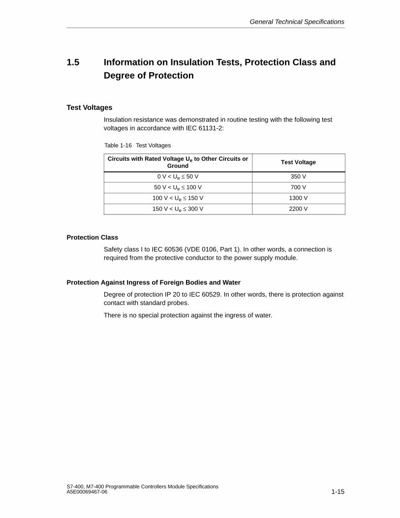
General Technical Specifications
1-15S7-400, M7-400 Programmable Controllers Module SpecificationsA5E00069467-06
1.5 Information on Insulation Tests, Protection Class andDegree of Protection
Test Voltages
Insulation resistance was demonstrated in routine testing with the following testvoltages in accordance with IEC 61131-2:
Table 1-16 Test Voltages
Circuits with Rated Voltage Ue to Other Circuits orGround
Test Voltage
0 V < Ue ≤ 50 V 350 V
50 V < Ue ≤ 100 V 700 V
100 V < Ue ≤ 150 V 1300 V
150 V < Ue ≤ 300 V 2200 V
Protection Class
Safety class I to IEC 60536 (VDE 0106, Part 1). In other words, a connection isrequired from the protective conductor to the power supply module.
Protection Against Ingress of Foreign Bodies and Water
Degree of protection IP 20 to IEC 60529. In other words, there is protection againstcontact with standard probes.
There is no special protection against the ingress of water.

General Technical Specifications
1-16S7-400, M7-400 Programmable Controllers Module Specifications
A5E00069467-06
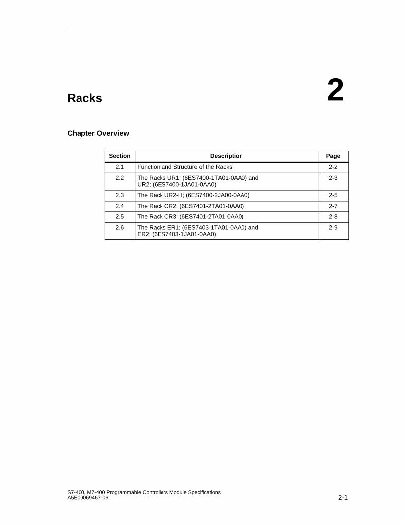
Racks
2-1S7-400, M7-400 Programmable Controllers Module SpecificationsA5E00069467-06
Racks
Chapter Overview
Section Description Page
2.1 Function and Structure of the Racks 2-2
2.2 The Racks UR1; (6ES7400-1TA01-0AA0) and UR2; (6ES7400-1JA01-0AA0)
2-3
2.3 The Rack UR2-H; (6ES7400-2JA00-0AA0) 2-5
2.4 The Rack CR2; (6ES7401-2TA01-0AA0) 2-7
2.5 The Rack CR3; (6ES7401-2TA01-0AA0) 2-8
2.6 The Racks ER1; (6ES7403-1TA01-0AA0) and ER2; (6ES7403-1JA01-0AA0)
2-9
2
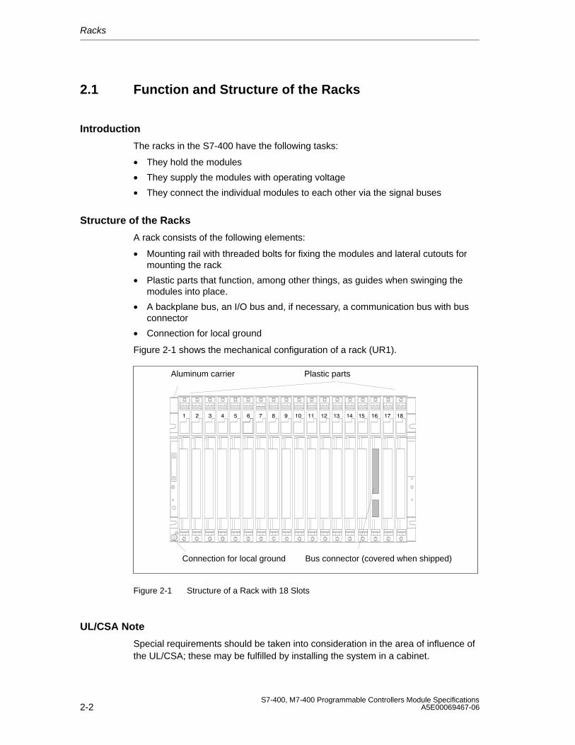
Racks
2-2S7-400, M7-400 Programmable Controllers Module Specifications
A5E00069467-06
2.1 Function and Structure of the Racks
Introduction
The racks in the S7-400 have the following tasks:
• They hold the modules
• They supply the modules with operating voltage
• They connect the individual modules to each other via the signal buses
Structure of the Racks
A rack consists of the following elements:
• Mounting rail with threaded bolts for fixing the modules and lateral cutouts formounting the rack
• Plastic parts that function, among other things, as guides when swinging themodules into place.
• A backplane bus, an I/O bus and, if necessary, a communication bus with busconnector
• Connection for local ground
Figure 2-1 shows the mechanical configuration of a rack (UR1).
Aluminum carrier Plastic parts
Connection for local ground Bus connector (covered when shipped)
Figure 2-1 Structure of a Rack with 18 Slots
UL/CSA Note
Special requirements should be taken into consideration in the area of influence ofthe UL/CSA; these may be fulfilled by installing the system in a cabinet.
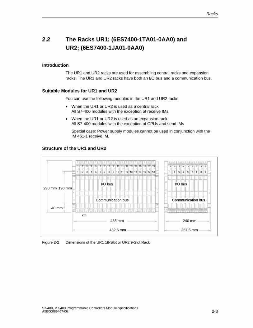
Racks
2-3S7-400, M7-400 Programmable Controllers Module SpecificationsA5E00069467-06
2.2 The Racks UR1; (6ES7400-1TA01-0AA0) and UR2; (6ES7400-1JA01-0AA0)
Introduction
The UR1 and UR2 racks are used for assembling central racks and expansionracks. The UR1 and UR2 racks have both an I/O bus and a communication bus.
Suitable Modules for UR1 and UR2
You can use the following modules in the UR1 and UR2 racks:
• When the UR1 or UR2 is used as a central rack: All S7-400 modules with the exception of receive IMs
• When the UR1 or UR2 is used as an expansion rack: All S7-400 modules with the exception of CPUs and send IMs
Special case: Power supply modules cannot be used in conjunction with theIM 461-1 receive IM.
Structure of the UR1 and UR2
465 mm 240 mm
482.5 mm 257.5 mm
290 mm 190 mm
40 mm
I/O bus
Communication bus
I/O bus
Communication bus
Figure 2-2 Dimensions of the UR1 18-Slot or UR2 9-Slot Rack
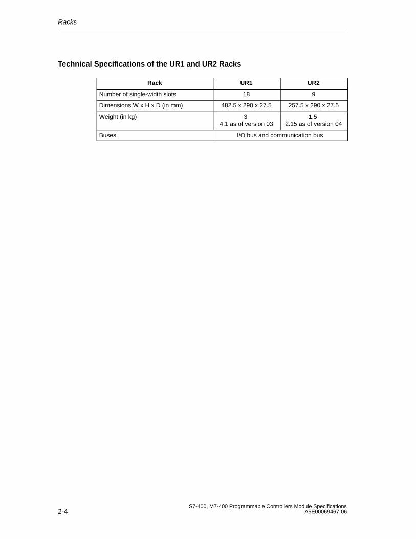
Racks
2-4S7-400, M7-400 Programmable Controllers Module Specifications
A5E00069467-06
Technical Specifications of the UR1 and UR2 Racks
Rack UR1 UR2
Number of single-width slots 18 9
Dimensions W x H x D (in mm) 482.5 x 290 x 27.5 257.5 x 290 x 27.5
Weight (in kg) 3 4.1 as of version 03
1.5 2.15 as of version 04
Buses I/O bus and communication bus
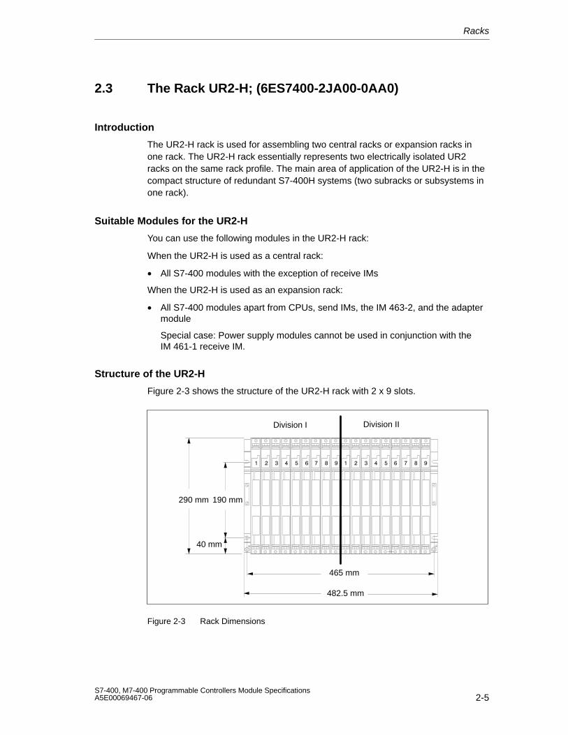
Racks
2-5S7-400, M7-400 Programmable Controllers Module SpecificationsA5E00069467-06
2.3 The Rack UR2-H; (6ES7400-2JA00-0AA0)
Introduction
The UR2-H rack is used for assembling two central racks or expansion racks inone rack. The UR2-H rack essentially represents two electrically isolated UR2racks on the same rack profile. The main area of application of the UR2-H is in thecompact structure of redundant S7-400H systems (two subracks or subsystems inone rack).
Suitable Modules for the UR2-H
You can use the following modules in the UR2-H rack:
When the UR2-H is used as a central rack:
• All S7-400 modules with the exception of receive IMs
When the UR2-H is used as an expansion rack:
• All S7-400 modules apart from CPUs, send IMs, the IM 463-2, and the adaptermodule
Special case: Power supply modules cannot be used in conjunction with theIM 461-1 receive IM.
Structure of the UR2-H
Figure 2-3 shows the structure of the UR2-H rack with 2 x 9 slots.
465 mm
482.5 mm
290 mm 190 mm
40 mm
Division I Division II
Figure 2-3 Rack Dimensions
Racks
2-6S7-400, M7-400 Programmable Controllers Module Specifications
A5E00069467-06
!Caution
Danger of damage to equipment.
If you insert a power supply module in a slot that is not permitted for power supplymodules, the module may be damaged. Slots 1 to 4 are permitted, whereby powersupply modules starting from slot 1 must be inserted without leaving gaps.
Make sure that power supply modules are only inserted in permitted slots. Takeparticular notice of the option of swapping modules in slot 1 on subrack II and slot9 on subrack I.
Technical Specifications of the UR2-H Rack
Rack UR2-H
Number of single-width slots 2 x 9
Dimensions W x H x D (in mm) 482.5 x 290 x 27.5
Weight (in kg) 34.1 as of version 03
Buses Segmented I/O bus, segmented communication bus
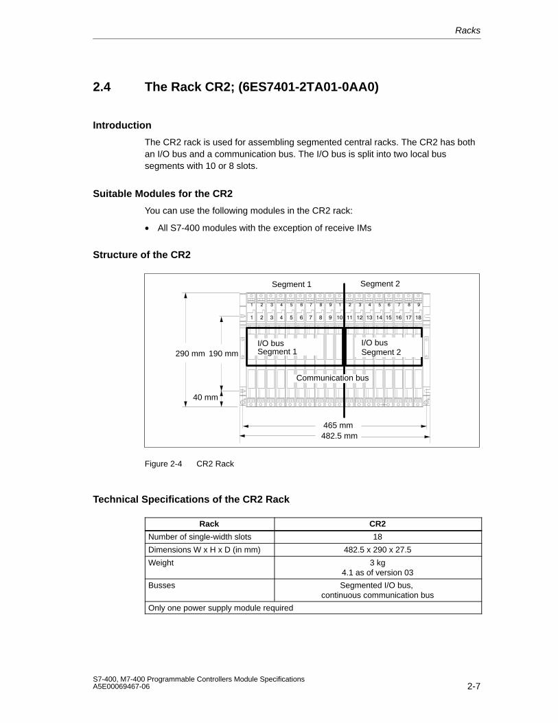
Racks
2-7S7-400, M7-400 Programmable Controllers Module SpecificationsA5E00069467-06
2.4 The Rack CR2; (6ES7401-2TA01-0AA0)
Introduction
The CR2 rack is used for assembling segmented central racks. The CR2 has bothan I/O bus and a communication bus. The I/O bus is split into two local bussegments with 10 or 8 slots.
Suitable Modules for the CR2
You can use the following modules in the CR2 rack:
• All S7-400 modules with the exception of receive IMs
Structure of the CR2
465 mm482.5 mm
290 mm 190 mm
40 mm
Segment 1 Segment 2
I/O busSegment 1
I/O busSegment 2
Communication bus
Figure 2-4 CR2 Rack
Technical Specifications of the CR2 Rack
Rack CR2
Number of single-width slots 18
Dimensions W x H x D (in mm) 482.5 x 290 x 27.5
Weight 3 kg4.1 as of version 03
Busses Segmented I/O bus, continuous communication bus
Only one power supply module required
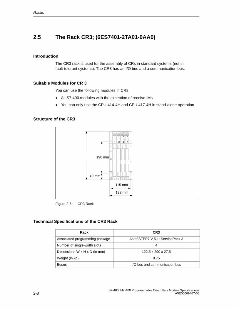
Racks
2-8S7-400, M7-400 Programmable Controllers Module Specifications
A5E00069467-06
2.5 The Rack CR3; (6ES7401-2TA01-0AA0)
Introduction
The CR3 rack is used for the assembly of CRs in standard systems (not infault-tolerant systems). The CR3 has an I/O bus and a communication bus.
Suitable Modules for CR 3
You can use the following modules in CR3:
• All S7-400 modules with the exception of receive IMs
• You can only use the CPU 414-4H and CPU 417-4H in stand-alone operation.
Structure of the CR3
190 mm
40 mm
115 mm
132 mm
Figure 2-5 CR3 Rack
Technical Specifications of the CR3 Rack
Rack CR3
Associated programming package As of STEP7 V 5.1; ServicePack 3
Number of single-width slots 4
Dimensions W x H x D (in mm) 122.5 x 290 x 27.5
Weight (in kg) 0.75
Buses I/O bus and communication bus
Racks
2-9S7-400, M7-400 Programmable Controllers Module SpecificationsA5E00069467-06
2.6 The Racks ER1; (6ES7403-1TA01-0AA0) and ER2; (6ES7403-1JA01-0AA0)
Introduction
The ER1 and ER2 racks are used for assembling expansion racks.
The ER1 and ER2 racks have only one I/O bus with the following restrictions:
• Interrupts from modules in the ER1 or ER2 have no effect since there are nointerrupt lines provided.
• Modules in the ER1 or ER2 are not supplied with 24 V. Modules requiring a24 V supply are not provided for use in the ER1 or ER2.
• Modules in the ER1 or ER2 are not backed up either by the battery in the powersupply module or by the voltage supplied externally to the CPU or the receiveIM (EXT.-BATT. socket).
There is therefore no advantage in using backup batteries in the power supplymodules in ER1 and ER2.
Battery faults and backup voltage faults are not reported to the CPU. The battery monitoring function of a power supply module installed in the ER1or ER2 should therefore always be switched off.
Suitable Modules for ER1 and ER2
You can use the following modules in the ER1 and ER2 racks:
• All power supply modules
• Receive IMs
• All signal modules provided the above-mentioned restrictions are observed.
However: Power supply modules cannot be used in conjunction with the IM 461-1receive IM.
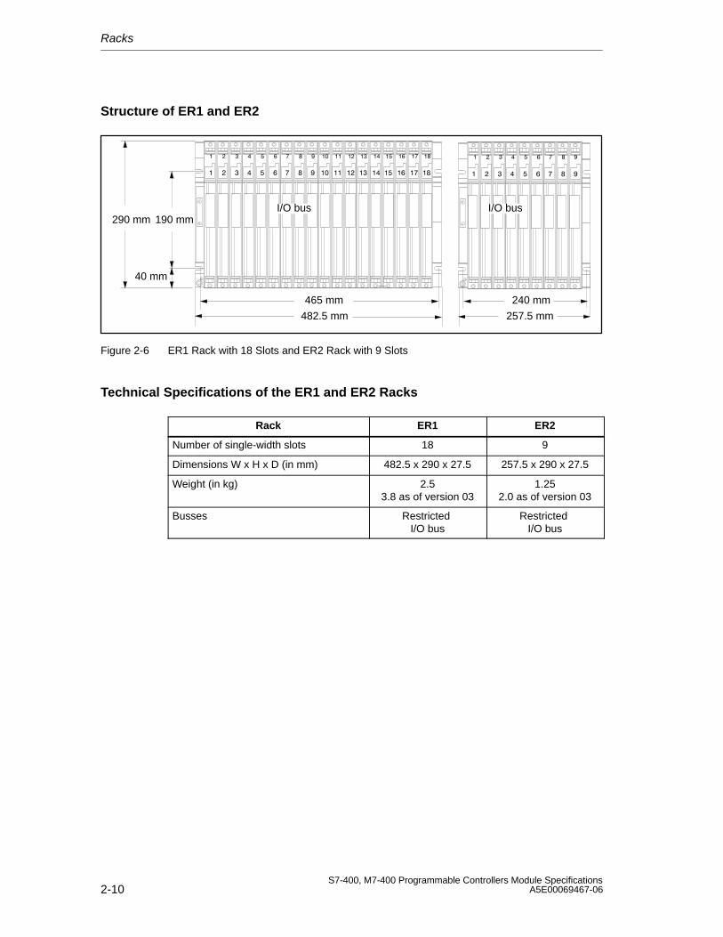
Racks
2-10S7-400, M7-400 Programmable Controllers Module Specifications
A5E00069467-06
Structure of ER1 and ER2
465 mm 240 mm
482.5 mm 257.5 mm
290 mm 190 mm
40 mm
I/O bus I/O bus
Figure 2-6 ER1 Rack with 18 Slots and ER2 Rack with 9 Slots
Technical Specifications of the ER1 and ER2 Racks
Rack ER1 ER2
Number of single-width slots 18 9
Dimensions W x H x D (in mm) 482.5 x 290 x 27.5 257.5 x 290 x 27.5
Weight (in kg) 2.53.8 as of version 03
1.252.0 as of version 03
Busses Restricted I/O bus
Restricted I/O bus
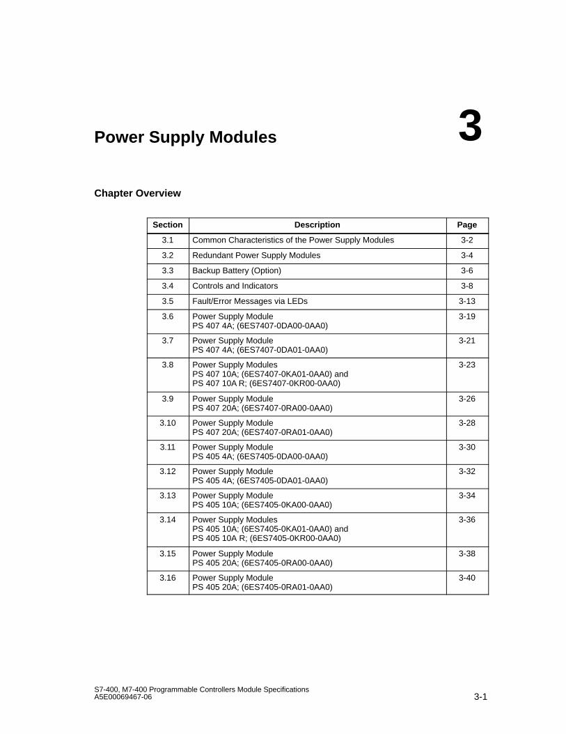
3-1S7-400, M7-400 Programmable Controllers Module SpecificationsA5E00069467-06
Power Supply Modules
Chapter Overview
Section Description Page
3.1 Common Characteristics of the Power Supply Modules 3-2
3.2 Redundant Power Supply Modules 3-4
3.3 Backup Battery (Option) 3-6
3.4 Controls and Indicators 3-8
3.5 Fault/Error Messages via LEDs 3-13
3.6 Power Supply Module PS 407 4A; (6ES7407-0DA00-0AA0)
3-19
3.7 Power Supply Module PS 407 4A; (6ES7407-0DA01-0AA0)
3-21
3.8 Power Supply ModulesPS 407 10A; (6ES7407-0KA01-0AA0) and PS 407 10A R; (6ES7407-0KR00-0AA0)
3-23
3.9 Power Supply Module PS 407 20A; (6ES7407-0RA00-0AA0)
3-26
3.10 Power Supply Module PS 407 20A; (6ES7407-0RA01-0AA0)
3-28
3.11 Power Supply Module PS 405 4A; (6ES7405-0DA00-0AA0)
3-30
3.12 Power Supply Module PS 405 4A; (6ES7405-0DA01-0AA0)
3-32
3.13 Power Supply Module PS 405 10A; (6ES7405-0KA00-0AA0)
3-34
3.14 Power Supply Modules PS 405 10A; (6ES7405-0KA01-0AA0) and PS 405 10A R; (6ES7405-0KR00-0AA0)
3-36
3.15 Power Supply Module PS 405 20A; (6ES7405-0RA00-0AA0)
3-38
3.16 Power Supply Module PS 405 20A; (6ES7405-0RA01-0AA0)
3-40
3
Power Supply Modules
3-2S7-400, M7-400 Programmable Controllers Module Specifications
A5E00069467-06
3.1 Common Characteristics of the Power Supply Modules
Tasks of the Power Supply Modules
The power supply modules of the S7-400 supply the other modules in the rack withtheir operating voltages via the backplane bus. They do not provide load voltagesfor the signal modules.
Common Characteristics of the Power Supply Modules
The power supply modules share certain common characteristics in addition totheir special technical specifications. The most important common characteristicsare:
• Encapsulated design for use in mounting racks of the S7-400 system
• Cooling via natural convection
• Plug-in connection of the supply voltage with AC - DC coding
• Protection class I (with protective conductor) in accordance with IEC 60536;VDE 0106, Part 1
• Limitation of making current in accordance with NAMUR recommendation part 1of August 1998
• Short circuit-proof outputs
• Monitoring of both output voltages. If one of these voltages fails, the powersupply module signals a fault to the CPU.
• Both output voltages (5 VDC and 24 VDC) share a common ground.
• Primary clocked
• Battery backup as option. The parameters set and the memory contents (RAM)are backed up via the backplane bus in the CPUs and programmable modules.In addition, the backup battery enables you to carry out a restart of the CPU.Both the power supply module and the backed up modules monitor the batteryvoltage.
• Operating and fault/error LEDs on the front plate.
Warning
A mains disconnecting device must be provided when installing AC power supplymodules.
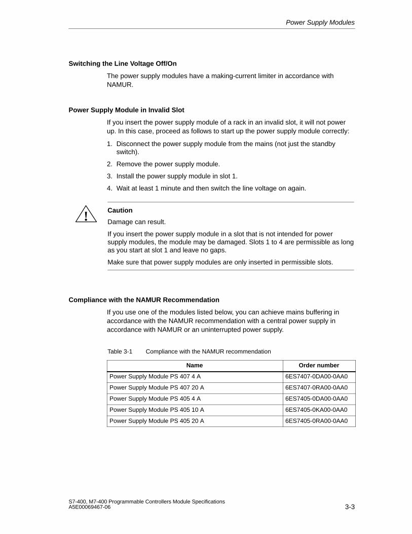
Power Supply Modules
3-3S7-400, M7-400 Programmable Controllers Module SpecificationsA5E00069467-06
Switching the Line Voltage Off/On
The power supply modules have a making-current limiter in accordance withNAMUR.
Power Supply Module in Invalid Slot
If you insert the power supply module of a rack in an invalid slot, it will not powerup. In this case, proceed as follows to start up the power supply module correctly:
1. Disconnect the power supply module from the mains (not just the standbyswitch).
2. Remove the power supply module.
3. Install the power supply module in slot 1.
4. Wait at least 1 minute and then switch the line voltage on again.
!Caution
Damage can result.
If you insert the power supply module in a slot that is not intended for powersupply modules, the module may be damaged. Slots 1 to 4 are permissible as longas you start at slot 1 and leave no gaps.
Make sure that power supply modules are only inserted in permissible slots.
Compliance with the NAMUR Recommendation
If you use one of the modules listed below, you can achieve mains buffering inaccordance with the NAMUR recommendation with a central power supply inaccordance with NAMUR or an uninterrupted power supply.
Table 3-1 Compliance with the NAMUR recommendation
Name Order number
Power Supply Module PS 407 4 A 6ES7407-0DA00-0AA0
Power Supply Module PS 407 20 A 6ES7407-0RA00-0AA0
Power Supply Module PS 405 4 A 6ES7405-0DA00-0AA0
Power Supply Module PS 405 10 A 6ES7405-0KA00-0AA0
Power Supply Module PS 405 20 A 6ES7405-0RA00-0AA0
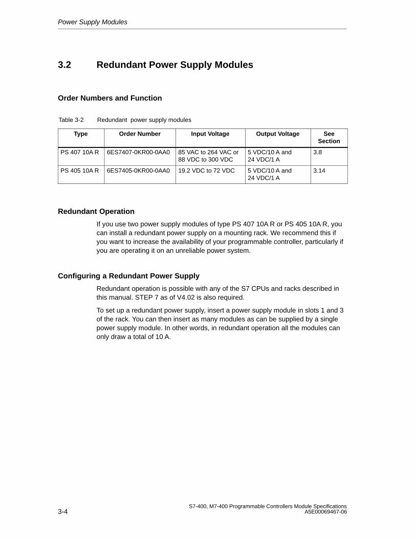
Power Supply Modules
3-4S7-400, M7-400 Programmable Controllers Module Specifications
A5E00069467-06
3.2 Redundant Power Supply Modules
Order Numbers and Function
Table 3-2 Redundant power supply modules
Type Order Number Input Voltage Output Voltage SeeSection
PS 407 10A R 6ES7407-0KR00-0AA0 85 VAC to 264 VAC or88 VDC to 300 VDC
5 VDC/10 A and24 VDC/1 A
3.8
PS 405 10A R 6ES7405-0KR00-0AA0 19.2 VDC to 72 VDC 5 VDC/10 A and24 VDC/1 A
3.14
Redundant Operation
If you use two power supply modules of type PS 407 10A R or PS 405 10A R, youcan install a redundant power supply on a mounting rack. We recommend this ifyou want to increase the availability of your programmable controller, particularly ifyou are operating it on an unreliable power system.
Configuring a Redundant Power Supply
Redundant operation is possible with any of the S7 CPUs and racks described inthis manual. STEP 7 as of V4.02 is also required.
To set up a redundant power supply, insert a power supply module in slots 1 and 3of the rack. You can then insert as many modules as can be supplied by a singlepower supply module. In other words, in redundant operation all the modules canonly draw a total of 10 A.
Power Supply Modules
3-5S7-400, M7-400 Programmable Controllers Module SpecificationsA5E00069467-06
Characteristics
The redundant power supply of an S7-400 has the following characteristics:
• The power supply module delivers a making current in accordance withNAMUR.
• Each of the power supply modules can take over the supply of power to thewhole rack if the other one fails. There is no loss of operation.
• Each of the power supply modules can be exchanged while the system is inoperation. No loss of power and no peak stress occurs with the effectivevoltages when the modules are removed or inserted.
• Each of the power supply modules monitors its function and sends a message ifit fails.
• Neither of the power supply modules can generate an error which affects theoutput voltage of the other power supply module.
• A redundant battery concept (backup concept) is only provided when twobackup batteries are used in each of the power supply modules. If only onebattery is used in each module, only non-redundant backup is possible, sinceboth batteries are being used at the same time.
• The failure of a power supply module is registered via a plug and removeinterrupt (default STOP). Only if used in the second segment of the CR 2 is nomessage sent if the power supply module fails.
• If two power supply modules are inserted but only one is switched on, there is apower-up delay of up to one minute when the line voltage is switched on.
Note
The check box “Startup if preset configuration not equal to actual configuration”should be activated in the “Properties” dialog box of the CPU.
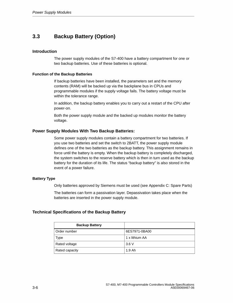
Power Supply Modules
3-6S7-400, M7-400 Programmable Controllers Module Specifications
A5E00069467-06
3.3 Backup Battery (Option)
Introduction
The power supply modules of the S7-400 have a battery compartment for one ortwo backup batteries. Use of these batteries is optional.
Function of the Backup Batteries
If backup batteries have been installed, the parameters set and the memorycontents (RAM) will be backed up via the backplane bus in CPUs andprogrammable modules if the supply voltage fails. The battery voltage must bewithin the tolerance range.
In addition, the backup battery enables you to carry out a restart of the CPU afterpower-on.
Both the power supply module and the backed up modules monitor the batteryvoltage.
Power Supply Modules With Two Backup Batteries:
Some power supply modules contain a battery compartment for two batteries. Ifyou use two batteries and set the switch to 2BATT, the power supply moduledefines one of the two batteries as the backup battery. This assignment remains inforce until the battery is empty. When the backup battery is completely discharged,the system switches to the reserve battery which is then in turn used as the backupbattery for the duration of its life. The status “backup battery” is also stored in theevent of a power failure.
Battery Type
Only batteries approved by Siemens must be used (see Appendix C: Spare Parts)
The batteries can form a passivation layer. Depassivation takes place when thebatteries are inserted in the power supply module.
Technical Specifications of the Backup Battery
Backup Battery
Order number 6ES7971-0BA00
Type 1 x lithium AA
Rated voltage 3.6 V
Rated capacity 1.9 Ah
Power Supply Modules
3-7S7-400, M7-400 Programmable Controllers Module SpecificationsA5E00069467-06
Backup Times
The maximum backup time is based on the capacity of the backup batteries usedand the backup current in the rack. The backup current is the sum of all individualcurrents of the inserted backed-up modules as well as the requirements of thepower supply module when the power is switched off.
Example for the Calculation of Backup Times
The capacity of the batteries is listed in the technical specifications of the powersupply. The typical and maximum backup current of the backed-up module is listedin the technical specifications of the module.
The typical backup current of a CPU is an empirically determined value. Themaximum backup current is a worst-case value that is calculated based on thecorresponding manufacturer specifications for the memory blocks.
The following technical specifications produce backup times for a CR with a PS407 4A and a CPU 417-4 as the only backed-up module:
Capacity of the backup battery: 1.9 Ah
Maximum backup current (including own requirement at power off) of the powersupply:100 µA
Typical backup current of the CPU 417-4: 75 µA
A rated capacity of less than 100% is to be assumed when calculating the backuptime because the backup battery is also affected at power on by the regulardepassivation.
A battery capacity of 63% of the rated capacity produces the following values:
Backup time = 1.9 Ah * 0.63 / (100 + 75)µA = (1.197 / 175) * 1 000 000 = 6840 h
This produces a maximum backup time of 285 days.
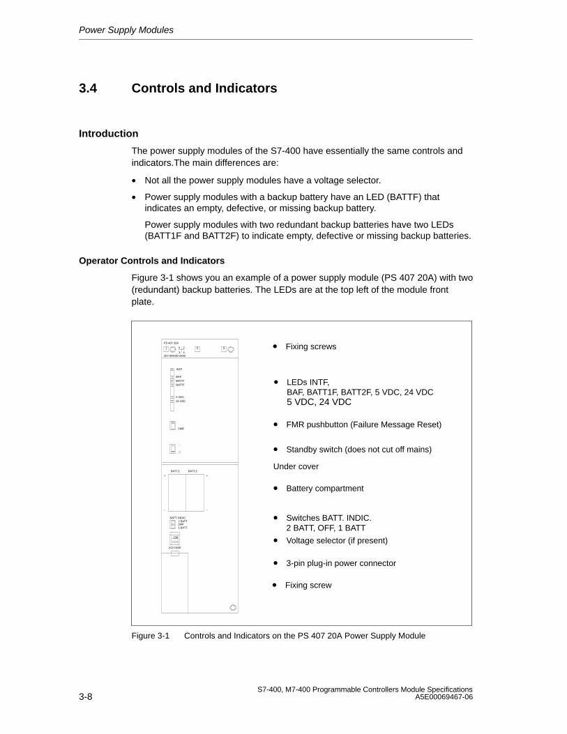
Power Supply Modules
3-8S7-400, M7-400 Programmable Controllers Module Specifications
A5E00069467-06
3.4 Controls and Indicators
Introduction
The power supply modules of the S7-400 have essentially the same controls andindicators.The main differences are:
• Not all the power supply modules have a voltage selector.
• Power supply modules with a backup battery have an LED (BATTF) thatindicates an empty, defective, or missing backup battery.
Power supply modules with two redundant backup batteries have two LEDs(BATT1F and BATT2F) to indicate empty, defective or missing backup batteries.
Operator Controls and Indicators
Figure 3-1 shows you an example of a power supply module (PS 407 20A) with two(redundant) backup batteries. The LEDs are at the top left of the module frontplate.
• FMR pushbutton (Failure Message Reset)
• Standby switch (does not cut off mains)
• Switches BATT. INDIC.2 BATT, OFF, 1 BATT
• Voltage selector (if present)
• Battery compartment
• 3-pin plug-in power connector
• Fixing screw
• Fixing screws
• LEDs INTF, BAF, BATT1F, BATT2F, 5 VDC, 24 VDC5 VDC, 24 VDC
PS 407 20A
407-0RA00-0AA0
X 2
3 41
FMR
BATT. INDIC.2 BATT
230
VOLTAGE
1 BATTOFF
INTF
BAF
BATTF
5 VDC
24 VDC
BATTF
2 3
BATT.1 BATT.2
+
–
+
–
Under cover
Figure 3-1 Controls and Indicators on the PS 407 20A Power Supply Module
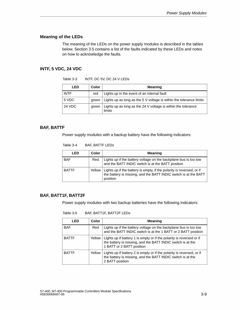
Power Supply Modules
3-9S7-400, M7-400 Programmable Controllers Module SpecificationsA5E00069467-06
Meaning of the LEDs
The meaning of the LEDs on the power supply modules is described in the tablesbelow. Section 3.5 contains a list of the faults indicated by these LEDs and noteson how to acknowledge the faults.
INTF, 5 VDC, 24 VDC
Table 3-3 INTF, DC 5V, DC 24 V LEDs
LED Color Meaning
INTF red Lights up in the event of an internal fault
5 VDC green Lights up as long as the 5 V voltage is within the tolerance limits
24 VDC green Lights up as long as the 24 V voltage is within the tolerancelimits
BAF, BATTF
Power supply modules with a backup battery have the following indicators:
Table 3-4 BAF, BATTF LEDs
LED Color Meaning
BAF Red Lights up if the battery voltage on the backplane bus is too lowand the BATT INDIC switch is at the BATT position
BATTF Yellow Lights up if the battery is empty, if the polarity is reversed, or ifthe battery is missing, and the BATT INDIC switch is at the BATTposition
BAF, BATT1F, BATT2F
Power supply modules with two backup batteries have the following indicators:
Table 3-5 BAF, BATT1F, BATT2F LEDs
LED Color Meaning
BAF Red Lights up if the battery voltage on the backplane bus is too lowand the BATT INDIC switch is at the 1 BATT or 2 BATT position
BATTF Yellow Lights up if battery 1 is empty or if the polarity is reversed or ifthe battery is missing, and the BATT INDIC switch is at the1 BATT or 2 BATT position
BATTF Yellow Lights up if battery 2 is empty or if the polarity is reversed, or ifthe battery is missing, and the BATT INDIC switch is at the2 BATT position
Power Supply Modules
3-10S7-400, M7-400 Programmable Controllers Module Specifications
A5E00069467-06
Battery Voltage on the Backplane Bus
The battery voltage is either supplied by the backup battery or externally into theCPU or receive IM. In its normal state, the level of the battery voltage is between2.7 V and 3.6 V.
The battery voltage is monitored for the lower limit. Violation of the lower limit isindicated by the BAF LED and reported to the CPU.
BAF lights up if the battery voltage on the backplane bus is too low. Possiblecauses of this include:
• Battery (batteries) empty or battery polarity has been reversed.
• External supply via CPU or receive IM is defective or supply from secondarypower supply module is defective or missing.
• Short circuit or overload on the battery voltage.
Note
Due to internal capacities, if you remove the battery or switch off the externalsupply, some time may elapse before BAF, BATT1F, or BATT2F lights up.
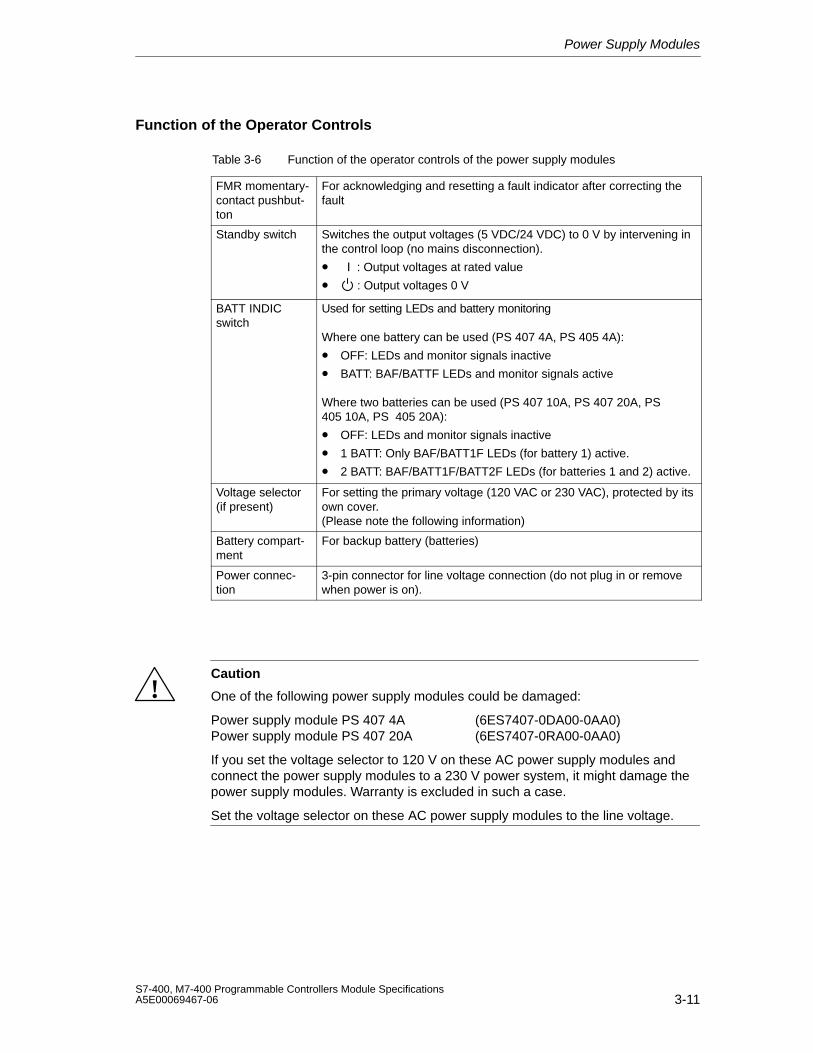
Power Supply Modules
3-11S7-400, M7-400 Programmable Controllers Module SpecificationsA5E00069467-06
Function of the Operator Controls
Table 3-6 Function of the operator controls of the power supply modules
FMR momentary-contact pushbut-ton
For acknowledging and resetting a fault indicator after correcting thefault
Standby switch Switches the output voltages (5 VDC/24 VDC) to 0 V by intervening inthe control loop (no mains disconnection).
• : Output voltages at rated value
• : Output voltages 0 V
BATT INDICswitch
Used for setting LEDs and battery monitoring
Where one battery can be used (PS 407 4A, PS 405 4A):
• OFF: LEDs and monitor signals inactive
• BATT: BAF/BATTF LEDs and monitor signals active
Where two batteries can be used (PS 407 10A, PS 407 20A, PS405 10A, PS 405 20A):
• OFF: LEDs and monitor signals inactive
• 1 BATT: Only BAF/BATT1F LEDs (for battery 1) active.
• 2 BATT: BAF/BATT1F/BATT2F LEDs (for batteries 1 and 2) active.
Voltage selector (if present)
For setting the primary voltage (120 VAC or 230 VAC), protected by itsown cover.(Please note the following information)
Battery compart-ment
For backup battery (batteries)
Power connec-tion
3-pin connector for line voltage connection (do not plug in or removewhen power is on).
!Caution
One of the following power supply modules could be damaged:
Power supply module PS 407 4A (6ES7407-0DA00-0AA0)Power supply module PS 407 20A (6ES7407-0RA00-0AA0)
If you set the voltage selector to 120 V on these AC power supply modules andconnect the power supply modules to a 230 V power system, it might damage thepower supply modules. Warranty is excluded in such a case.
Set the voltage selector on these AC power supply modules to the line voltage.
Power Supply Modules
3-12S7-400, M7-400 Programmable Controllers Module Specifications
A5E00069467-06
Cover
The battery compartment, battery selector switch, voltage selector switch andpower connection are housed under one cover. The cover must remain closedduring operation in order to protect these operator controls and to prevent staticelectricity from affecting the battery connections.
If you have to carry out measurements on a module, you must discharge your bodybefore you start the measurement by touching grounded metallic parts. Usegrounded measuring devices only.
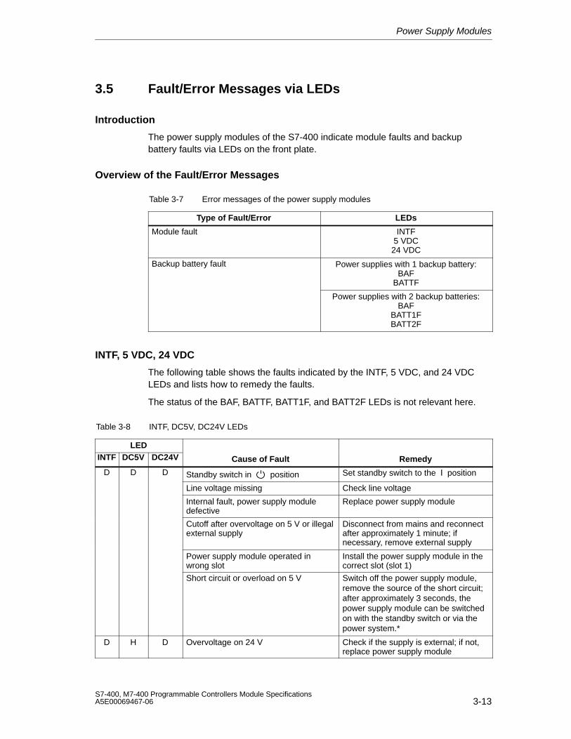
Power Supply Modules
3-13S7-400, M7-400 Programmable Controllers Module SpecificationsA5E00069467-06
3.5 Fault/Error Messages via LEDs
Introduction
The power supply modules of the S7-400 indicate module faults and backupbattery faults via LEDs on the front plate.
Overview of the Fault/Error Messages
Table 3-7 Error messages of the power supply modules
Type of Fault/Error LEDs
Module fault INTF5 VDC24 VDC
Backup battery fault Power supplies with 1 backup battery:BAF
BATTF
Power supplies with 2 backup batteries:BAF
BATT1FBATT2F
INTF, 5 VDC, 24 VDC
The following table shows the faults indicated by the INTF, 5 VDC, and 24 VDCLEDs and lists how to remedy the faults.
The status of the BAF, BATTF, BATT1F, and BATT2F LEDs is not relevant here.
Table 3-8 INTF, DC5V, DC24V LEDs
LEDINTF DC5V DC24V Cause of Fault Remedy
D D D Standby switch in position Set standby switch to the position
Line voltage missing Check line voltage
Internal fault, power supply moduledefective
Replace power supply module
Cutoff after overvoltage on 5 V or illegalexternal supply
Disconnect from mains and reconnectafter approximately 1 minute; ifnecessary, remove external supply
Power supply module operated inwrong slot
Install the power supply module in thecorrect slot (slot 1)
Short circuit or overload on 5 V Switch off the power supply module,remove the source of the short circuit;after approximately 3 seconds, thepower supply module can be switchedon with the standby switch or via thepower system.*
D H D Overvoltage on 24 V Check if the supply is external; if not,replace power supply module
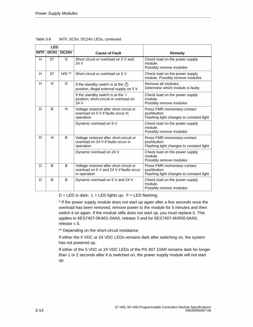
Power Supply Modules
3-14S7-400, M7-400 Programmable Controllers Module Specifications
A5E00069467-06
Table 3-8 INTF, DC5V, DC24V LEDs, continued
LEDINTF RemedyCause of FaultDC24VDC5V
H D* D Short circuit or overload on 5 V and24 V
Check load on the power supplymodule. Possibly remove modules
H D* H/D ** Short circuit or overload on 5 V Check load on the power supplymodule. Possibly remove modules
H H D If the standby switch is at theposition, illegal external supply on 5 V
Remove all modules. Determine which module is faulty
If the standby switch is at the position, short-circuit or overload on24 V
Check load on the power supplymodule. Possibly remove modules
D B H Voltage restored after short circuit oroverload on 5 V if faults occur inoperation
Press FMR momentary-contactpushbutton: Flashing light changes to constant light
Dynamic overload on 5 V Check load on the power supplymodule. Possibly remove modules
D H B Voltage restored after short-circuit oroverload on 24 V if faults occur inoperation
Press FMR momentary-contactpushbutton: Flashing light changes to constant light
Dynamic overload on 24 V Check load on the power supplymodule. Possibly remove modules
D B B Voltage restored after short circuit oroverload on 5 V and 24 V if faults occurin operation
Press FMR momentary-contactpushbutton: Flashing light changes to constant light
D B B Dynamic overload on 5 V and 24 V Check load on the power supplymodule. Possibly remove modules
D = LED is dark; L = LED lights up; F = LED flashing;
* If the power supply module does not start up again after a few seconds once theoverload has been removed, remove power to the module for 5 minutes and thenswitch it on again. If the module stills does not start up, you must replace it. Thisapplies to 6ES7407-0KA01-0AA0, release 3 and for 6ES7407-0KR00-0AA0,release ≤ 5.
** Depending on the short-circuit resistance
If either the 5 VDC or 24 VDC LEDs remains dark after switching on, the systemhas not powered up.
If either of the 5 VDC or 24 VDC LEDs of the PS 407 10AR remains dark for longerthan 1 or 2 seconds after it is switched on, the power supply module will not startup.
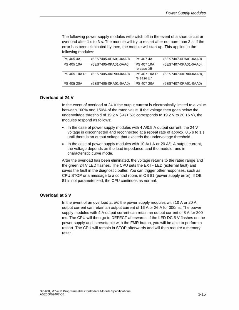
Power Supply Modules
3-15S7-400, M7-400 Programmable Controllers Module SpecificationsA5E00069467-06
The following power supply modules will switch off in the event of a short circuit oroverload after 1 s to 3 s. The module will try to restart after no more than 3 s. If theerror has been eliminated by then, the module will start up. This applies to thefollowing modules:
PS 405 4A (6ES7405-0DA01-0AA0) PS 407 4A (6ES7407-0DA01-0AA0)
PS 405 10A (6ES7405-0KA01-0AA0) PS 407 10A (6ES7407-0KA01-0AA0),release ≥5
PS 405 10A R (6ES7405-0KR00-0AA0) PS 407 10A R (6ES7407-0KR00-0AA0),release ≥7
PS 405 20A (6ES7405-0RA01-0AA0) PS 407 20A (6ES7407-0RA01-0AA0)
Overload at 24 V
In the event of overload at 24 V the output current is electronically limited to a valuebetween 100% and 150% of the rated value. If the voltage then goes below theundervoltage threshold of 19.2 V (–0/+ 5% corresponds to 19.2 V to 20.16 V), themodules respond as follows:
• In the case of power supply modules with 4 A/0.5 A output current, the 24 Vvoltage is disconnected and reconnected at a repeat rate of approx. 0.5 s to 1 suntil there is an output voltage that exceeds the undervoltage threshold.
• In the case of power supply modules with 10 A/1 A or 20 A/1 A output current,the voltage depends on the load impedance, and the module runs incharacteristic curve mode.
After the overload has been eliminated, the voltage returns to the rated range andthe green 24 V LED flashes. The CPU sets the EXTF LED (external fault) andsaves the fault in the diagnostic buffer. You can trigger other responses, such asCPU STOP or a message to a control room, in OB 81 (power supply error). If OB81 is not parameterized, the CPU continues as normal.
Overload at 5 V
In the event of an overload at 5V, the power supply modules with 10 A or 20 Aoutput current can retain an output current of 16 A or 26 A for 300ms. The powersupply modules with 4 A output current can retain an output current of 8 A for 300ms. The CPU will then go to DEFECT afterwards. If the LED DC 5 V flashes on thepower supply and is resettable with the FMR button, you will be able to perform arestart. The CPU will remain in STOP afterwards and will then require a memoryreset.
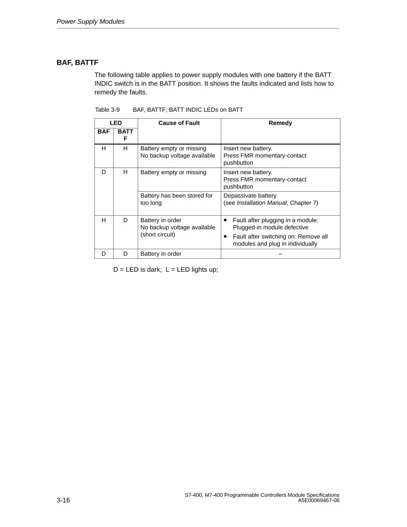
Power Supply Modules
3-16S7-400, M7-400 Programmable Controllers Module Specifications
A5E00069467-06
BAF, BATTF
The following table applies to power supply modules with one battery if the BATTINDIC switch is in the BATT position. It shows the faults indicated and lists how toremedy the faults.
Table 3-9 BAF, BATTF; BATT INDIC LEDs on BATT
LED Cause of Fault RemedyBAF BATT
F
H H Battery empty or missingNo backup voltage available
Insert new battery.Press FMR momentary-contactpushbutton
D H Battery empty or missing Insert new battery.Press FMR momentary-contactpushbutton
Battery has been stored for Depassivate battery too long (see Installation Manual, Chapter 7)
H D Battery in orderNo backup voltage available(short circuit)
• Fault after plugging in a module:Plugged-in module defective
• Fault after switching on: Remove allmodules and plug in individually
D D Battery in order –
D = LED is dark; L = LED lights up;
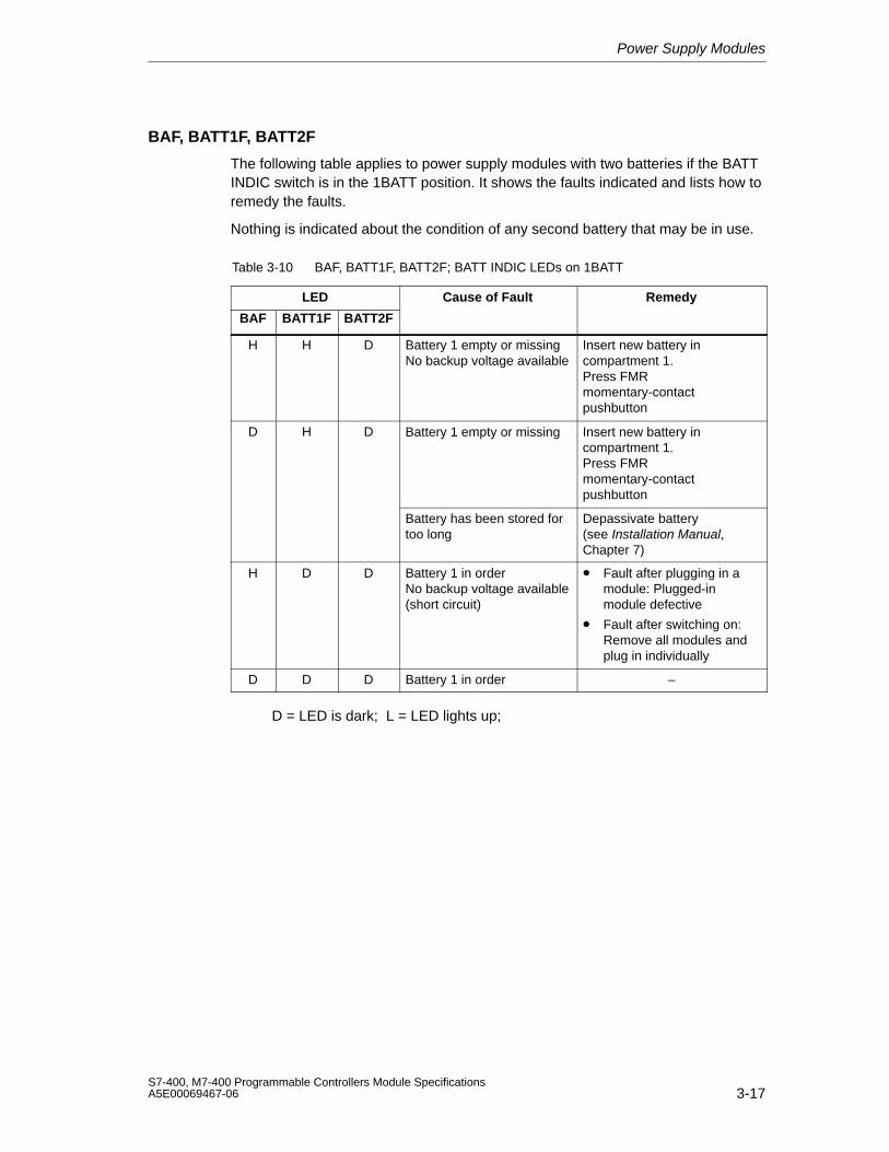
Power Supply Modules
3-17S7-400, M7-400 Programmable Controllers Module SpecificationsA5E00069467-06
BAF, BATT1F, BATT2F
The following table applies to power supply modules with two batteries if the BATTINDIC switch is in the 1BATT position. It shows the faults indicated and lists how toremedy the faults.
Nothing is indicated about the condition of any second battery that may be in use.
Table 3-10 BAF, BATT1F, BATT2F; BATT INDIC LEDs on 1BATT
LED Cause of Fault Remedy
BAF BATT1F BATT2F
H H D Battery 1 empty or missingNo backup voltage available
Insert new battery incompartment 1.Press FMRmomentary-contactpushbutton
D H D Battery 1 empty or missing Insert new battery incompartment 1.Press FMRmomentary-contactpushbutton
Battery has been stored fortoo long
Depassivate battery (see Installation Manual,Chapter 7)
H D D Battery 1 in orderNo backup voltage available(short circuit)
• Fault after plugging in amodule: Plugged-inmodule defective
• Fault after switching on:Remove all modules andplug in individually
D D D Battery 1 in order –
D = LED is dark; L = LED lights up;
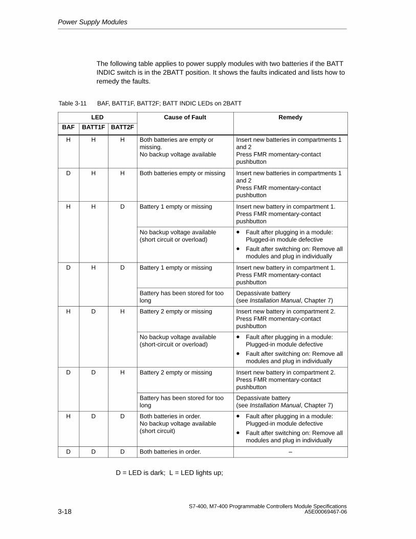
Power Supply Modules
3-18S7-400, M7-400 Programmable Controllers Module Specifications
A5E00069467-06
The following table applies to power supply modules with two batteries if the BATTINDIC switch is in the 2BATT position. It shows the faults indicated and lists how toremedy the faults.
Table 3-11 BAF, BATT1F, BATT2F; BATT INDIC LEDs on 2BATT
LED Cause of Fault Remedy
BAF BATT1F BATT2F
H H H Both batteries are empty ormissing.No backup voltage available
Insert new batteries in compartments 1and 2Press FMR momentary-contactpushbutton
D H H Both batteries empty or missing Insert new batteries in compartments 1and 2Press FMR momentary-contactpushbutton
H H D Battery 1 empty or missing Insert new battery in compartment 1.Press FMR momentary-contactpushbutton
No backup voltage available(short circuit or overload)
• Fault after plugging in a module:Plugged-in module defective
• Fault after switching on: Remove allmodules and plug in individually
D H D Battery 1 empty or missing Insert new battery in compartment 1.Press FMR momentary-contactpushbutton
Battery has been stored for toolong
Depassivate battery (see Installation Manual, Chapter 7)
H D H Battery 2 empty or missing Insert new battery in compartment 2.Press FMR momentary-contactpushbutton
No backup voltage available(short-circuit or overload)
• Fault after plugging in a module:Plugged-in module defective
• Fault after switching on: Remove allmodules and plug in individually
D D H Battery 2 empty or missing Insert new battery in compartment 2.Press FMR momentary-contactpushbutton
Battery has been stored for toolong
Depassivate battery (see Installation Manual, Chapter 7)
H D D Both batteries in order.No backup voltage available(short circuit)
• Fault after plugging in a module:Plugged-in module defective
• Fault after switching on: Remove allmodules and plug in individually
D D D Both batteries in order. –
D = LED is dark; L = LED lights up;
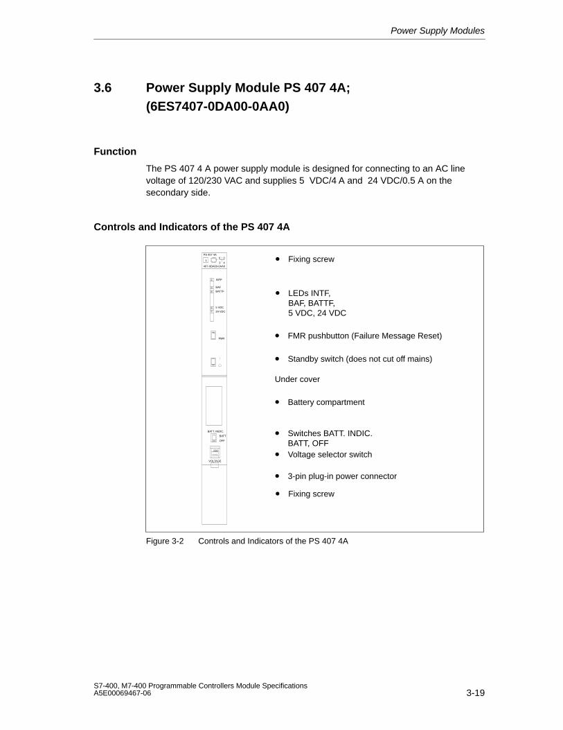
Power Supply Modules
3-19S7-400, M7-400 Programmable Controllers Module SpecificationsA5E00069467-06
3.6 Power Supply Module PS 407 4A;(6ES7407-0DA00-0AA0)
Function
The PS 407 4 A power supply module is designed for connecting to an AC linevoltage of 120/230 VAC and supplies 5 VDC/4 A and 24 VDC/0.5 A on thesecondary side.
Controls and Indicators of the PS 407 4A
• LEDs INTF, BAF, BATTF, 5 VDC, 24 VDC
• FMR pushbutton (Failure Message Reset)
• Standby switch (does not cut off mains)
• Switches BATT. INDIC.BATT, OFF
• Voltage selector switch
• Battery compartment
• 3-pin plug-in power connector
• Fixing screwPS 407 4A
1X 2
3 4407-0DA00-0AA0
FMR
BATT. INDIC.
BATT
OFF
230
INTF
BAF
BATTF
5 VDC
24 VDC
VOLTAGE
Under cover
• Fixing screw
Figure 3-2 Controls and Indicators of the PS 407 4A
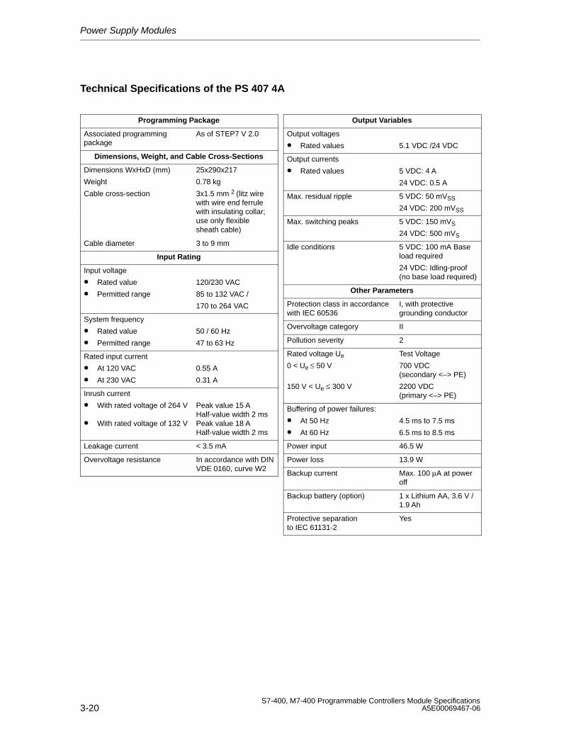
Power Supply Modules
3-20S7-400, M7-400 Programmable Controllers Module Specifications
A5E00069467-06
Technical Specifications of the PS 407 4A
Programming Package
Associated programmingpackage
As of STEP7 V 2.0
Dimensions, Weight, and Cable Cross-Sections
Dimensions WxHxD (mm)
Weight
25x290x217
0.78 kg
Cable cross-section 3x1.5 mm 2 (litz wirewith wire end ferrulewith insulating collar;use only flexiblesheath cable)
Cable diameter 3 to 9 mm
Input Rating
Input voltage
• Rated value
• Permitted range
120/230 VAC
85 to 132 VAC /
170 to 264 VAC
System frequency
• Rated value
• Permitted range
50 / 60 Hz
47 to 63 Hz
Rated input current
• At 120 VAC
• At 230 VAC
0.55 A
0.31 A
Inrush current
• With rated voltage of 264 V
• With rated voltage of 132 V
Peak value 15 A Half-value width 2 msPeak value 18 A Half-value width 2 ms
Leakage current < 3.5 mA
Overvoltage resistance In accordance with DINVDE 0160, curve W2
Output Variables
Output voltages
• Rated values 5.1 VDC /24 VDC
Output currents
• Rated values 5 VDC: 4 A
24 VDC: 0.5 A
Max. residual ripple 5 VDC: 50 mVSS
24 VDC: 200 mVSS
Max. switching peaks 5 VDC: 150 mVS
24 VDC: 500 mVS
Idle conditions 5 VDC: 100 mA Baseload required
24 VDC: Idling-proof(no base load required)
Other Parameters
Protection class in accordancewith IEC 60536
I, with protectivegrounding conductor
Overvoltage category II
Pollution severity 2
Rated voltage Ue
0 < Ue ≤ 50 V
150 V < Ue ≤ 300 V
Test Voltage
700 VDC(secondary <–> PE)
2200 VDC(primary <–> PE)
Buffering of power failures:
• At 50 Hz
• At 60 Hz
4.5 ms to 7.5 ms
6.5 ms to 8.5 ms
Power input 46.5 W
Power loss 13.9 W
Backup current Max. 100 µA at poweroff
Backup battery (option) 1 x Lithium AA, 3.6 V /1.9 Ah
Protective separationto IEC 61131-2
Yes
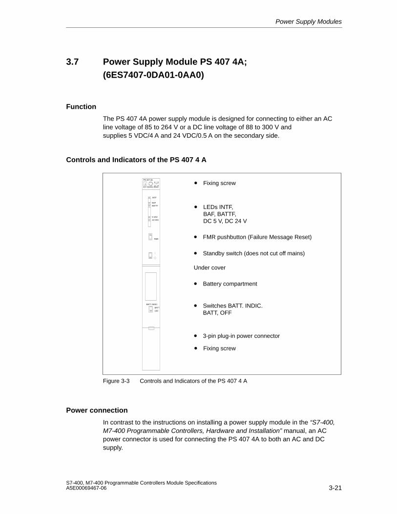
Power Supply Modules
3-21S7-400, M7-400 Programmable Controllers Module SpecificationsA5E00069467-06
3.7 Power Supply Module PS 407 4A;(6ES7407-0DA01-0AA0)
Function
The PS 407 4A power supply module is designed for connecting to either an ACline voltage of 85 to 264 V or a DC line voltage of 88 to 300 V andsupplies 5 VDC/4 A and 24 VDC/0.5 A on the secondary side.
Controls and Indicators of the PS 407 4 A
• LEDs INTF, BAF, BATTF, DC 5 V, DC 24 V
• FMR pushbutton (Failure Message Reset)
• Standby switch (does not cut off mains)
• Switches BATT. INDIC.BATT, OFF
• Battery compartment
• 3-pin plug-in power connector
• Fixing screwPS 407 4A
1X 2
3 4
FMR
BATT. INDIC.
BATT
OFF
INTF
BAF
BATTF
5 VDC
24 VDC
Under cover
• Fixing screw
407-0DA01-0AA0
Figure 3-3 Controls and Indicators of the PS 407 4 A
Power connection
In contrast to the instructions on installing a power supply module in the “S7-400,M7-400 Programmable Controllers, Hardware and Installation” manual, an ACpower connector is used for connecting the PS 407 4A to both an AC and DCsupply.
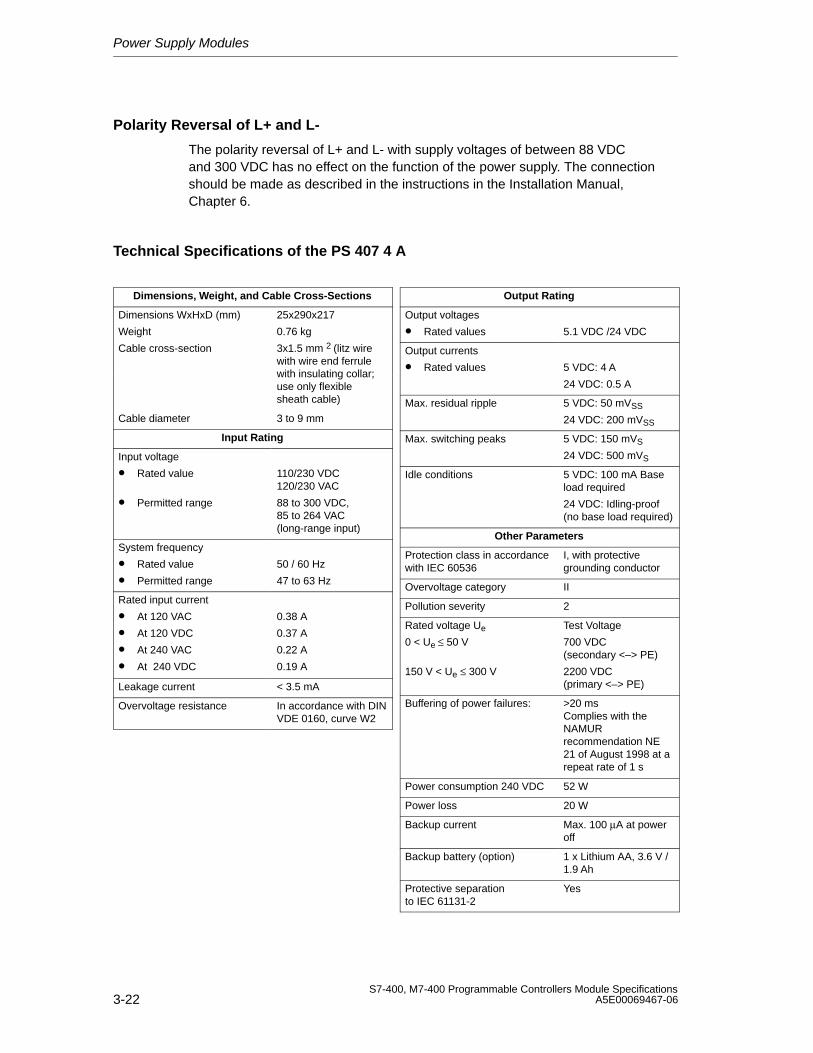
Power Supply Modules
3-22S7-400, M7-400 Programmable Controllers Module Specifications
A5E00069467-06
Polarity Reversal of L+ and L-
The polarity reversal of L+ and L- with supply voltages of between 88 VDCand 300 VDC has no effect on the function of the power supply. The connectionshould be made as described in the instructions in the Installation Manual,Chapter 6.
Technical Specifications of the PS 407 4 A
Dimensions, Weight, and Cable Cross-Sections
Dimensions WxHxD (mm)
Weight
25x290x217
0.76 kg
Cable cross-section 3x1.5 mm 2 (litz wirewith wire end ferrulewith insulating collar;use only flexiblesheath cable)
Cable diameter 3 to 9 mm
Input Rating
Input voltage
• Rated value
• Permitted range
110/230 VDC120/230 VAC
88 to 300 VDC,85 to 264 VAC (long-range input)
System frequency
• Rated value
• Permitted range
50 / 60 Hz
47 to 63 Hz
Rated input current
• At 120 VAC
• At 120 VDC
• At 240 VAC
• At 240 VDC
0.38 A
0.37 A
0.22 A
0.19 A
Leakage current < 3.5 mA
Overvoltage resistance In accordance with DINVDE 0160, curve W2
Output Rating
Output voltages
• Rated values 5.1 VDC /24 VDC
Output currents
• Rated values 5 VDC: 4 A
24 VDC: 0.5 A
Max. residual ripple 5 VDC: 50 mVSS
24 VDC: 200 mVSS
Max. switching peaks 5 VDC: 150 mVS
24 VDC: 500 mVS
Idle conditions 5 VDC: 100 mA Baseload required
24 VDC: Idling-proof(no base load required)
Other Parameters
Protection class in accordancewith IEC 60536
I, with protectivegrounding conductor
Overvoltage category II
Pollution severity 2
Rated voltage Ue
0 < Ue ≤ 50 V
150 V < Ue ≤ 300 V
Test Voltage
700 VDC(secondary <–> PE)
2200 VDC(primary <–> PE)
Buffering of power failures: >20 msComplies with theNAMURrecommendation NE21 of August 1998 at arepeat rate of 1 s
Power consumption 240 VDC 52 W
Power loss 20 W
Backup current Max. 100 µA at poweroff
Backup battery (option) 1 x Lithium AA, 3.6 V /1.9 Ah
Protective separationto IEC 61131-2
Yes
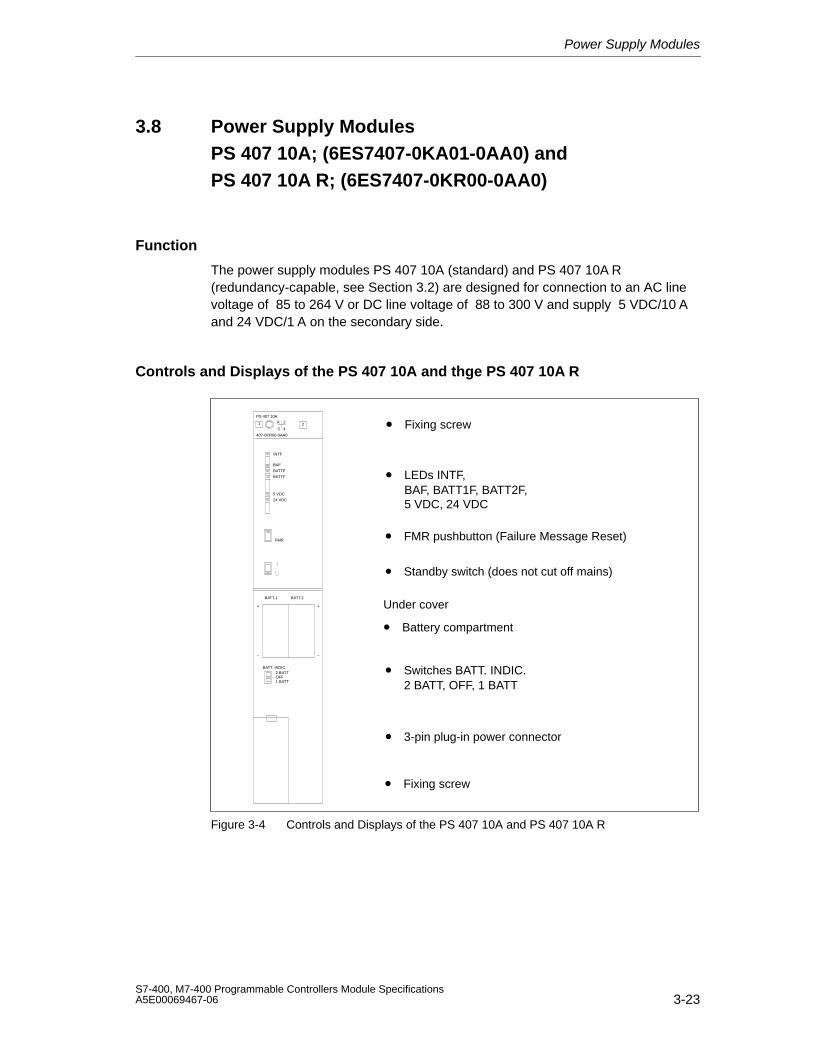
Power Supply Modules
3-23S7-400, M7-400 Programmable Controllers Module SpecificationsA5E00069467-06
3.8 Power Supply Modules PS 407 10A; (6ES7407-0KA01-0AA0) and PS 407 10A R; (6ES7407-0KR00-0AA0)
Function
The power supply modules PS 407 10A (standard) and PS 407 10A R (redundancy-capable, see Section 3.2) are designed for connection to an AC linevoltage of 85 to 264 V or DC line voltage of 88 to 300 V and supply 5 VDC/10 Aand 24 VDC/1 A on the secondary side.
Controls and Displays of the PS 407 10A and thge PS 407 10A R
• FMR pushbutton (Failure Message Reset)
• Standby switch (does not cut off mains)
• Switches BATT. INDIC.2 BATT, OFF, 1 BATT
• Battery compartment
• 3-pin plug-in power connector
• Fixing screw
• LEDs INTF, BAF, BATT1F, BATT2F, 5 VDC, 24 VDC
PS 407 10A
407-0KR00-0AA0
X 2
3 41
FMR
BATT. INDIC.2 BATT
1 BATTOFF
+
–
+
–
2
INTF
BAF
BATTF
5 VDC
24 VDC
BATTF
BATT.1 BATT.2
Under cover
• Fixing screw
Figure 3-4 Controls and Displays of the PS 407 10A and PS 407 10A R
Power Supply Modules
3-24S7-400, M7-400 Programmable Controllers Module Specifications
A5E00069467-06
Power Connection
In contrast to the instructions on installing a power supply module described in the“S7-400, M7-400 Programmable Controllers, Hardware and Installation” manual,an AC connector is used for connecting the PS 407 10A and the PS 407 10A R toboth an AC and a DC supply.
Polarity Reversal of L+ and L-
The polarity reversal of L+ and L- with supply voltages of between 88 VDCand 300 VDC has no effect on the function of the power supply. The connectionshould be made as described in the instructions in the Installation Manual,Chapter 6.
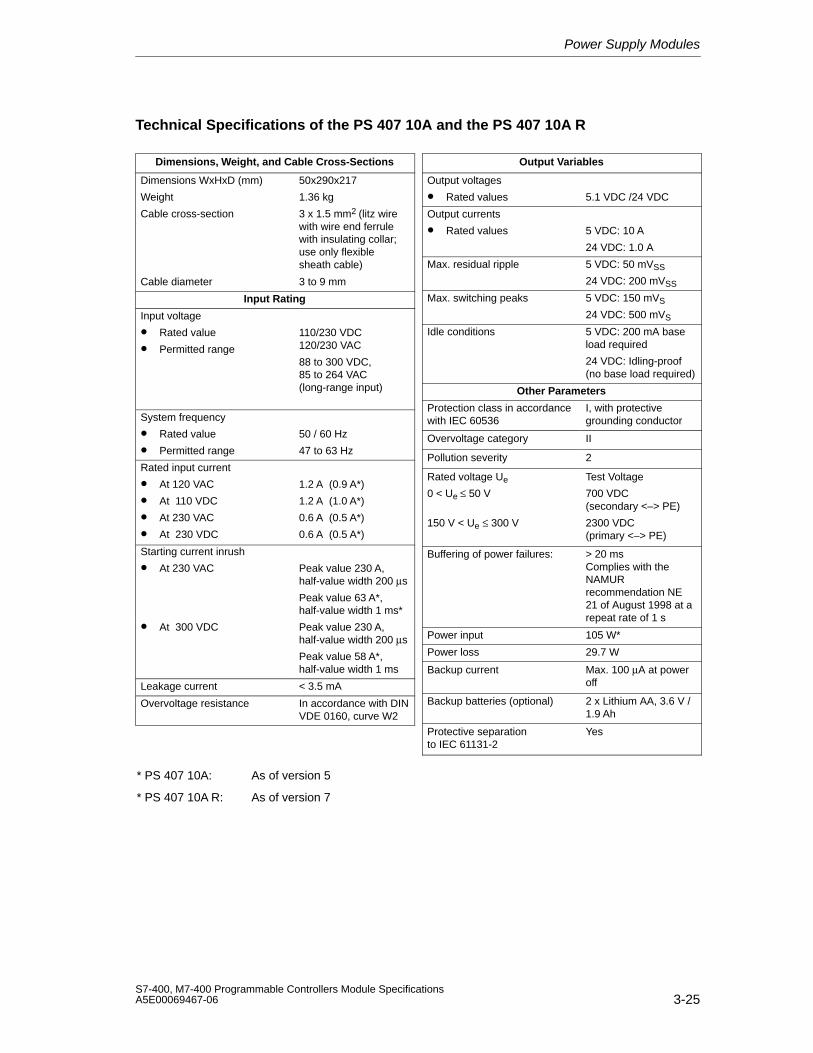
Power Supply Modules
3-25S7-400, M7-400 Programmable Controllers Module SpecificationsA5E00069467-06
Technical Specifications of the PS 407 10A and the PS 407 10A R
Dimensions, Weight, and Cable Cross-Sections
Dimensions WxHxD (mm)
Weight
Cable cross-section
50x290x217
1.36 kg
3 x 1.5 mm2 (litz wirewith wire end ferrulewith insulating collar;use only flexiblesheath cable)
Cable diameter 3 to 9 mm
Input Rating
Input voltage
• Rated value
• Permitted range
110/230 VDC 120/230 VAC
88 to 300 VDC, 85 to 264 VAC(long-range input)
System frequency
• Rated value
• Permitted range
50 / 60 Hz
47 to 63 Hz
Rated input current
• At 120 VAC
• At 110 VDC
• At 230 VAC
• At 230 VDC
1.2 A (0.9 A*)
1.2 A (1.0 A*)
0.6 A (0.5 A*)
0.6 A (0.5 A*)
Starting current inrush
• At 230 VAC Peak value 230 A,half-value width 200 µs
Peak value 63 A*,half-value width 1 ms*
• At 300 VDC Peak value 230 A,half-value width 200 µs
Peak value 58 A*,half-value width 1 ms
Leakage current < 3.5 mA
Overvoltage resistance In accordance with DINVDE 0160, curve W2
* PS 407 10A: As of version 5
* PS 407 10A R: As of version 7
Output Variables
Output voltages
• Rated values 5.1 VDC /24 VDC
Output currents
• Rated values 5 VDC: 10 A
24 VDC: 1.0 A
Max. residual ripple 5 VDC: 50 mVSS
24 VDC: 200 mVSS
Max. switching peaks 5 VDC: 150 mVS
24 VDC: 500 mVS
Idle conditions 5 VDC: 200 mA baseload required
24 VDC: Idling-proof(no base load required)
Other Parameters
Protection class in accordancewith IEC 60536
I, with protectivegrounding conductor
Overvoltage category II
Pollution severity 2
Rated voltage Ue
0 < Ue ≤ 50 V
150 V < Ue ≤ 300 V
Test Voltage
700 VDC(secondary <–> PE)
2300 VDC(primary <–> PE)
Buffering of power failures: > 20 msComplies with theNAMURrecommendation NE21 of August 1998 at arepeat rate of 1 s
Power input 105 W*
Power loss 29.7 W
Backup current Max. 100 µA at poweroff
Backup batteries (optional) 2 x Lithium AA, 3.6 V /1.9 Ah
Protective separationto IEC 61131-2
Yes
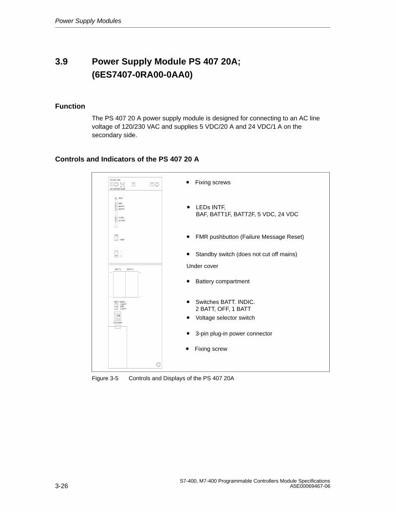
Power Supply Modules
3-26S7-400, M7-400 Programmable Controllers Module Specifications
A5E00069467-06
3.9 Power Supply Module PS 407 20A;(6ES7407-0RA00-0AA0)
Function
The PS 407 20 A power supply module is designed for connecting to an AC linevoltage of 120/230 VAC and supplies 5 VDC/20 A and 24 VDC/1 A on thesecondary side.
Controls and Indicators of the PS 407 20 A
• FMR pushbutton (Failure Message Reset)
• Standby switch (does not cut off mains)
• Switches BATT. INDIC.2 BATT, OFF, 1 BATT
• Voltage selector switch
• Battery compartment
• 3-pin plug-in power connector
• Fixing screw
• Fixing screws
• LEDs INTF, BAF, BATT1F, BATT2F, 5 VDC, 24 VDC
PS 407 20A
407-0RA00-0AA0
X 2
3 41
FMR
BATT. INDIC.2 BATT
230
VOLTAGE
1 BATTOFF
INTF
BAF
BATTF
5 VDC
24 VDC
BATTF
2 3
BATT.1 BATT.2
+
–
+
–
Under cover
Figure 3-5 Controls and Displays of the PS 407 20A
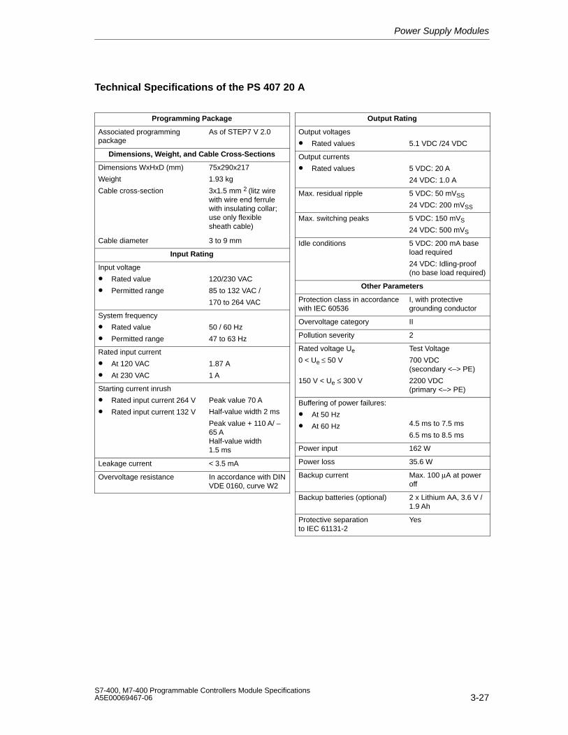
Power Supply Modules
3-27S7-400, M7-400 Programmable Controllers Module SpecificationsA5E00069467-06
Technical Specifications of the PS 407 20 A
Programming Package
Associated programmingpackage
As of STEP7 V 2.0
Dimensions, Weight, and Cable Cross-Sections
Dimensions WxHxD (mm)
Weight
Cable cross-section
75x290x217
1.93 kg
3x1.5 mm 2 (litz wirewith wire end ferrulewith insulating collar;use only flexiblesheath cable)
Cable diameter 3 to 9 mm
Input Rating
Input voltage
• Rated value
• Permitted range
120/230 VAC
85 to 132 VAC /
170 to 264 VAC
System frequency
• Rated value
• Permitted range
50 / 60 Hz
47 to 63 Hz
Rated input current
• At 120 VAC
• At 230 VAC
1.87 A
1 A
Starting current inrush
• Rated input current 264 V
• Rated input current 132 V
Peak value 70 A
Half-value width 2 ms
Peak value + 110 A/ –65 A Half-value width1.5 ms
Leakage current < 3.5 mA
Overvoltage resistance In accordance with DINVDE 0160, curve W2
Output Rating
Output voltages
• Rated values 5.1 VDC /24 VDC
Output currents
• Rated values 5 VDC: 20 A
24 VDC: 1.0 A
Max. residual ripple 5 VDC: 50 mVSS
24 VDC: 200 mVSS
Max. switching peaks 5 VDC: 150 mVS
24 VDC: 500 mVS
Idle conditions 5 VDC: 200 mA baseload required
24 VDC: Idling-proof(no base load required)
Other Parameters
Protection class in accordancewith IEC 60536
I, with protectivegrounding conductor
Overvoltage category II
Pollution severity 2
Rated voltage Ue
0 < Ue ≤ 50 V
150 V < Ue ≤ 300 V
Test Voltage
700 VDC(secondary <–> PE)
2200 VDC(primary <–> PE)
Buffering of power failures:
• At 50 Hz
• At 60 Hz 4.5 ms to 7.5 ms
6.5 ms to 8.5 ms
Power input 162 W
Power loss 35.6 W
Backup current Max. 100 µA at poweroff
Backup batteries (optional) 2 x Lithium AA, 3.6 V /1.9 Ah
Protective separationto IEC 61131-2
Yes
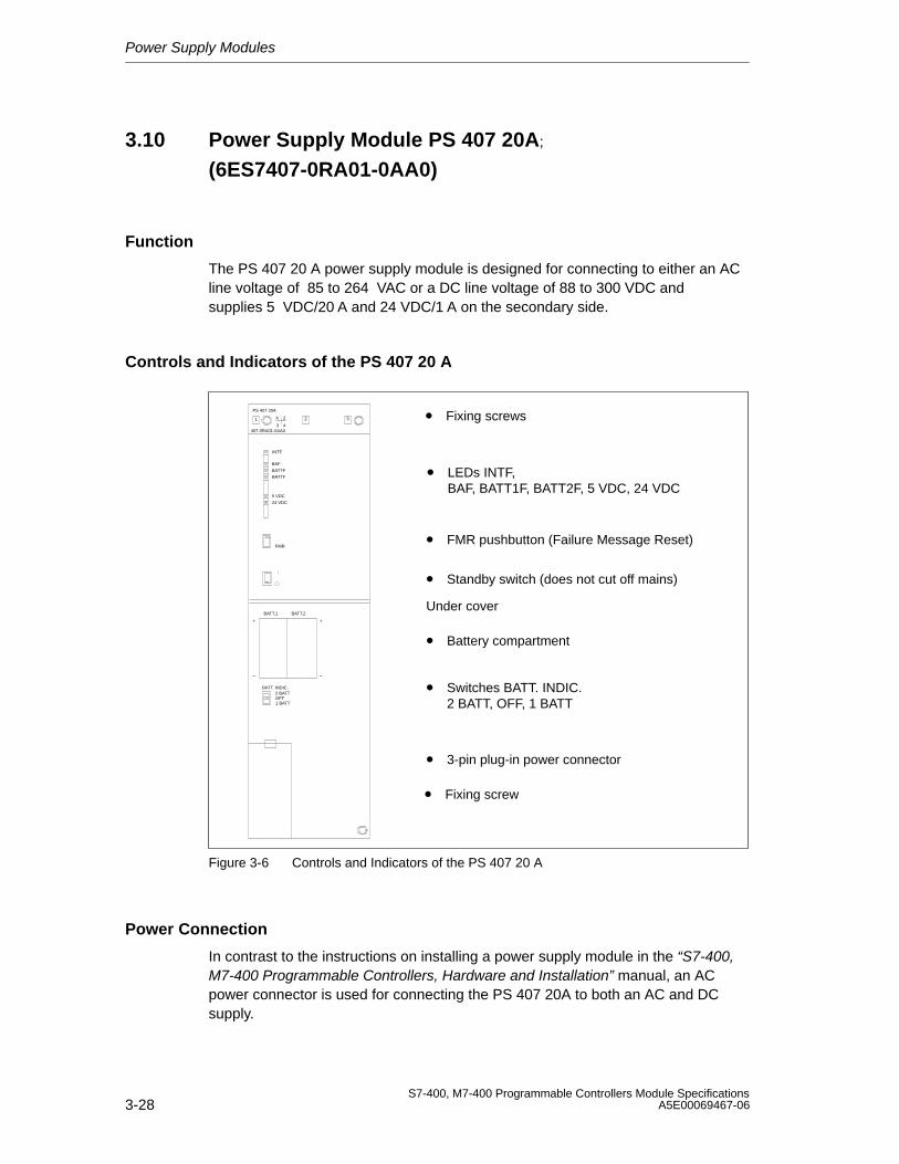
Power Supply Modules
3-28S7-400, M7-400 Programmable Controllers Module Specifications
A5E00069467-06
3.10 Power Supply Module PS 407 20A;
(6ES7407-0RA01-0AA0)
Function
The PS 407 20 A power supply module is designed for connecting to either an ACline voltage of 85 to 264 VAC or a DC line voltage of 88 to 300 VDC andsupplies 5 VDC/20 A and 24 VDC/1 A on the secondary side.
Controls and Indicators of the PS 407 20 A
• FMR pushbutton (Failure Message Reset)
• Standby switch (does not cut off mains)
• Switches BATT. INDIC.2 BATT, OFF, 1 BATT
• Battery compartment
• 3-pin plug-in power connector
• Fixing screw
• Fixing screws
• LEDs INTF, BAF, BATT1F, BATT2F, 5 VDC, 24 VDC
PS 407 20A
407-0RA01-0AA0
X 2
3 41
FMR
BATT. INDIC.2 BATT
1 BATTOFF
INTF
BAF
BATTF
5 VDC
24 VDC
BATTF
2 3
BATT.1 BATT.2
+
–
+
–
Under cover
Figure 3-6 Controls and Indicators of the PS 407 20 A
Power Connection
In contrast to the instructions on installing a power supply module in the “S7-400,M7-400 Programmable Controllers, Hardware and Installation” manual, an ACpower connector is used for connecting the PS 407 20A to both an AC and DCsupply.
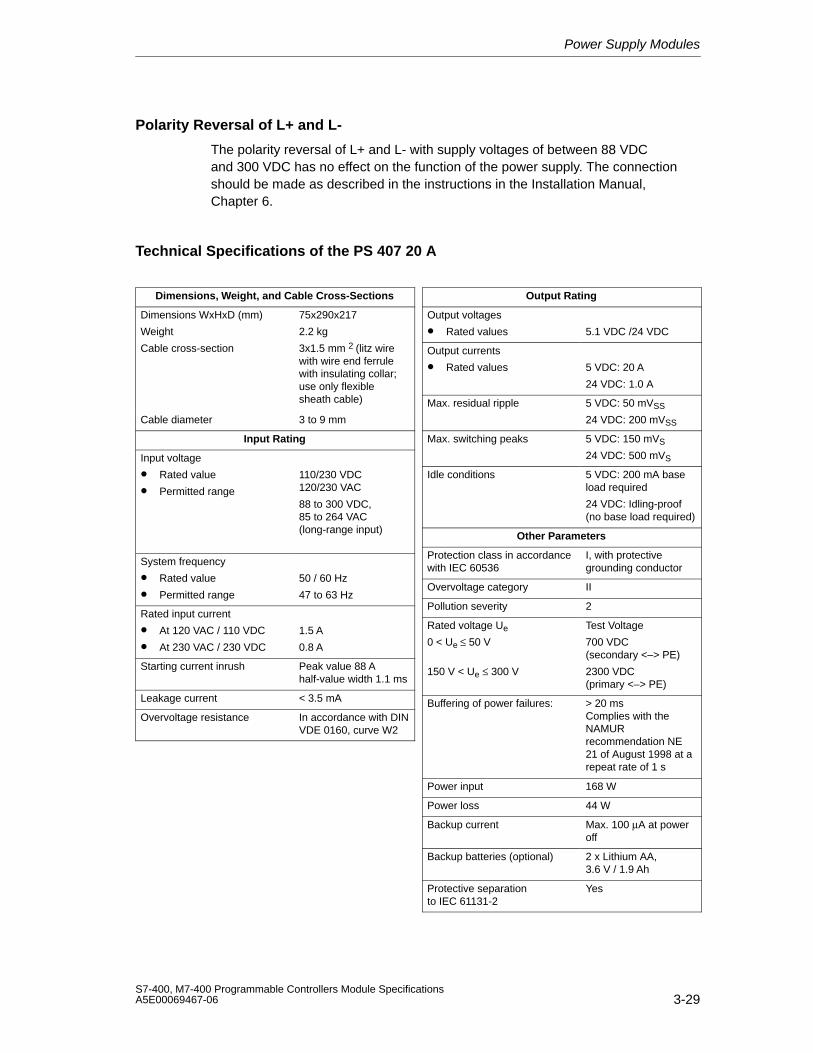
Power Supply Modules
3-29S7-400, M7-400 Programmable Controllers Module SpecificationsA5E00069467-06
Polarity Reversal of L+ and L-
The polarity reversal of L+ and L- with supply voltages of between 88 VDCand 300 VDC has no effect on the function of the power supply. The connectionshould be made as described in the instructions in the Installation Manual,Chapter 6.
Technical Specifications of the PS 407 20 A
Dimensions, Weight, and Cable Cross-Sections
Dimensions WxHxD (mm)
Weight
Cable cross-section
75x290x217
2.2 kg
3x1.5 mm 2 (litz wirewith wire end ferrulewith insulating collar;use only flexiblesheath cable)
Cable diameter 3 to 9 mm
Input Rating
Input voltage
• Rated value
• Permitted range
110/230 VDC 120/230 VAC
88 to 300 VDC, 85 to 264 VAC(long-range input)
System frequency
• Rated value
• Permitted range
50 / 60 Hz
47 to 63 Hz
Rated input current
• At 120 VAC / 110 VDC
• At 230 VAC / 230 VDC
1.5 A
0.8 A
Starting current inrush Peak value 88 A half-value width 1.1 ms
Leakage current < 3.5 mA
Overvoltage resistance In accordance with DINVDE 0160, curve W2
Output Rating
Output voltages
• Rated values 5.1 VDC /24 VDC
Output currents
• Rated values 5 VDC: 20 A
24 VDC: 1.0 A
Max. residual ripple 5 VDC: 50 mVSS
24 VDC: 200 mVSS
Max. switching peaks 5 VDC: 150 mVS
24 VDC: 500 mVS
Idle conditions 5 VDC: 200 mA baseload required
24 VDC: Idling-proof(no base load required)
Other Parameters
Protection class in accordancewith IEC 60536
I, with protectivegrounding conductor
Overvoltage category II
Pollution severity 2
Rated voltage Ue
0 < Ue ≤ 50 V
150 V < Ue ≤ 300 V
Test Voltage
700 VDC(secondary <–> PE)
2300 VDC(primary <–> PE)
Buffering of power failures: > 20 msComplies with theNAMURrecommendation NE21 of August 1998 at arepeat rate of 1 s
Power input 168 W
Power loss 44 W
Backup current Max. 100 µA at poweroff
Backup batteries (optional) 2 x Lithium AA, 3.6 V / 1.9 Ah
Protective separationto IEC 61131-2
Yes
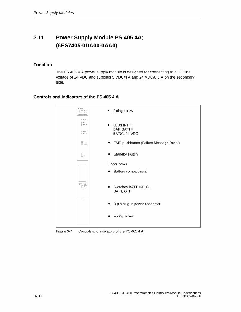
Power Supply Modules
3-30S7-400, M7-400 Programmable Controllers Module Specifications
A5E00069467-06
3.11 Power Supply Module PS 405 4A;(6ES7405-0DA00-0AA0)
Function
The PS 405 4 A power supply module is designed for connecting to a DC linevoltage of 24 VDC and supplies 5 VDC/4 A and 24 VDC/0.5 A on the secondaryside.
Controls and Indicators of the PS 405 4 A
• FMR pushbutton (Failure Message Reset)
• Standby switch
• Switches BATT. INDIC.BATT, OFF
• Battery compartment
• 3-pin plug-in power connector
• Fixing screw
• LEDs INTF, BAF, BATTF, 5 VDC, 24 VDC
PS 405 4A
405-0DA00-0AA0
X 2
3 41
INTF
BAF
BATTF
5 VDC
24 VDC
FMR
BATT. INDIC.
BATT
OFF
Under cover
• Fixing screw
Figure 3-7 Controls and Indicators of the PS 405 4 A

Power Supply Modules
3-31S7-400, M7-400 Programmable Controllers Module SpecificationsA5E00069467-06
Technical Specifications of the PS 405 4 A
Programming Package
Associated programmingpackage
As of STEP7 V 2.0
Dimensions, Weight, and Cable Cross-Sections
Dimensions WxHxD (mm)
Weight
25x290x217
0.8 kg
Cable cross-section 3 x 1.5 mm2 (litz wirewith wire end ferrule,use componentconductor or flexiblesheath cable)
Cable diameter 3 to 9 mm
Input Rating
Input voltage
• Rated value
• Permitted range
24 VDC
Static:19.2 VDC to 30 VDC
Dynamic:18.5 VDC to 30.2 VDC
Rated input current 2 A
Starting current inrush Peak value 27 AHalf-value width 10 ms
Overvoltage resistance In accordance with DINVDE 0160, curve B2
Output Rating
Output voltages
• Rated values 5.1 VDC /24 VDC
Output currents
• Rated values 5 VDC: 4 A
24 VDC: 0.5 A
Max. residual ripple 5 VDC: 50 mVSS
24 VDC: 200 mVSS
Max. switching peaks 5 VDC: 150 mVS
24 VDC: 500 mVS
Idle conditions 5 VDC: 100 mA Baseload required
24 VDC: Idling-proof(no base load required)
Other Parameters
Protection class in accordancewith IEC 60536
I, with protectivegrounding conductor
Overvoltage category II
Pollution severity 2
Rated voltage Ue
0 < Ue ≤ 50 V
150 V < Ue ≤ 300 V
Test Voltage
700 VDC(secondary <–> PE)
2200 VDC(primary <–> PE)
Buffering of power failures: 4 ms to 5 ms
Power input 48 W
Power loss 16 W
Backup current Max. 100 µA at poweroff
Backup battery (option) 1 x Lithium AA, 3.6 V /1.9 Ah
Protective separationto IEC 61131-2
Yes
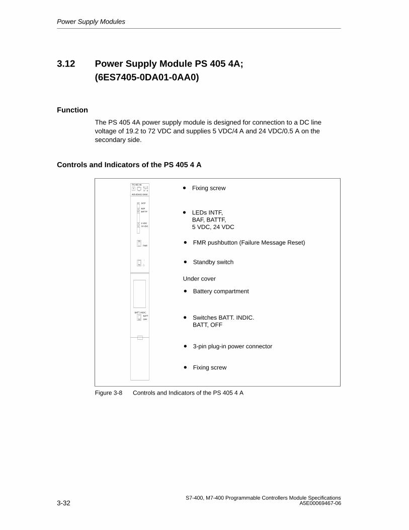
Power Supply Modules
3-32S7-400, M7-400 Programmable Controllers Module Specifications
A5E00069467-06
3.12 Power Supply Module PS 405 4A;(6ES7405-0DA01-0AA0)
Function
The PS 405 4A power supply module is designed for connection to a DC linevoltage of 19.2 to 72 VDC and supplies 5 VDC/4 A and 24 VDC/0.5 A on thesecondary side.
Controls and Indicators of the PS 405 4 A
• FMR pushbutton (Failure Message Reset)
• Standby switch
• Switches BATT. INDIC.BATT, OFF
• Battery compartment
• 3-pin plug-in power connector
• Fixing screw
• LEDs INTF, BAF, BATTF, 5 VDC, 24 VDC
PS 405 4AX 2
3 41
INTF
BAF
BATTF
5 VDC
24 VDC
FMR
BATT. INDIC.
BATT
OFF
Under cover
• Fixing screw
405-0DA01-0AA0
Figure 3-8 Controls and Indicators of the PS 405 4 A
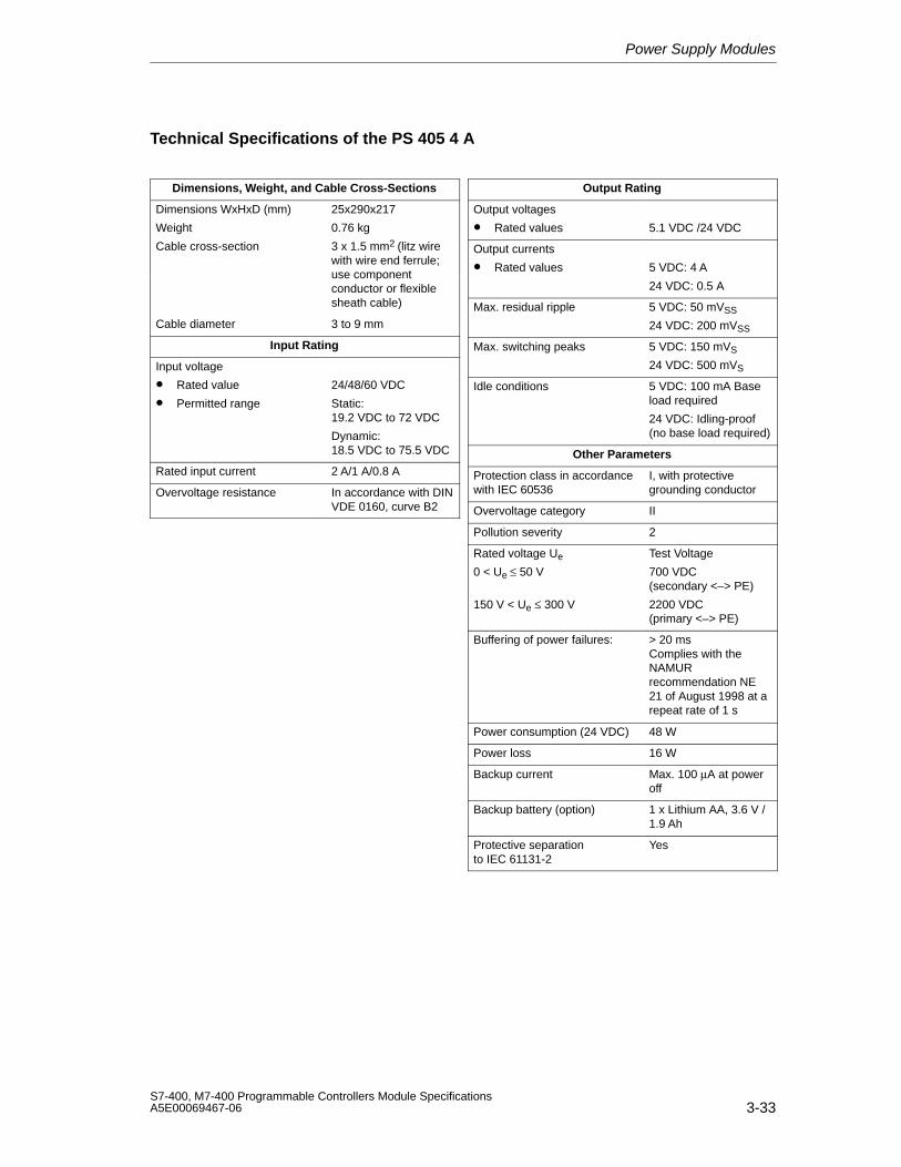
Power Supply Modules
3-33S7-400, M7-400 Programmable Controllers Module SpecificationsA5E00069467-06
Technical Specifications of the PS 405 4 A
Dimensions, Weight, and Cable Cross-Sections
Dimensions WxHxD (mm)
Weight
25x290x217
0.76 kg
Cable cross-section 3 x 1.5 mm2 (litz wirewith wire end ferrule;use componentconductor or flexiblesheath cable)
Cable diameter 3 to 9 mm
Input Rating
Input voltage
• Rated value
• Permitted range
24/48/60 VDC
Static:19.2 VDC to 72 VDC
Dynamic:18.5 VDC to 75.5 VDC
Rated input current 2 A/1 A/0.8 A
Overvoltage resistance In accordance with DINVDE 0160, curve B2
Output Rating
Output voltages
• Rated values 5.1 VDC /24 VDC
Output currents
• Rated values 5 VDC: 4 A
24 VDC: 0.5 A
Max. residual ripple 5 VDC: 50 mVSS
24 VDC: 200 mVSS
Max. switching peaks 5 VDC: 150 mVS
24 VDC: 500 mVS
Idle conditions 5 VDC: 100 mA Baseload required
24 VDC: Idling-proof(no base load required)
Other Parameters
Protection class in accordancewith IEC 60536
I, with protectivegrounding conductor
Overvoltage category II
Pollution severity 2
Rated voltage Ue
0 < Ue ≤ 50 V
150 V < Ue ≤ 300 V
Test Voltage
700 VDC(secondary <–> PE)
2200 VDC(primary <–> PE)
Buffering of power failures: > 20 msComplies with theNAMURrecommendation NE21 of August 1998 at arepeat rate of 1 s
Power consumption (24 VDC) 48 W
Power loss 16 W
Backup current Max. 100 µA at poweroff
Backup battery (option) 1 x Lithium AA, 3.6 V /1.9 Ah
Protective separationto IEC 61131-2
Yes
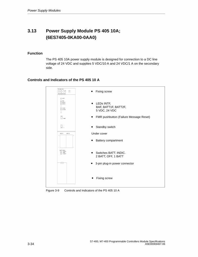
Power Supply Modules
3-34S7-400, M7-400 Programmable Controllers Module Specifications
A5E00069467-06
3.13 Power Supply Module PS 405 10A;(6ES7405-0KA00-0AA0)
Function
The PS 405 10A power supply module is designed for connection to a DC linevoltage of 24 VDC and supplies 5 VDC/10 A and 24 VDC/1 A on the secondaryside.
Controls and Indicators of the PS 405 10 A
• LEDs INTF, BAF, BATT1F, BATT2F, 5 VDC, 24 VDC
• FMR pushbutton (Failure Message Reset)
• Standby switch
• Switches BATT. INDIC.2 BATT, OFF, 1 BATT
• Battery compartment
• Fixing screw
• 3-pin plug-in power connector
PS 405 10 A
405-0KA00-0AA0
X 2
3 41
FMR
2
INTF
BAF
BATTF
5 VDC
24 VDC
BATTF
BATT. INDIC.2 BATT
1 BATTOFF
BATT.1 BATT.2
+
–
+
–
Under cover
• Fixing screw
Figure 3-9 Controls and Indicators of the PS 405 10 A
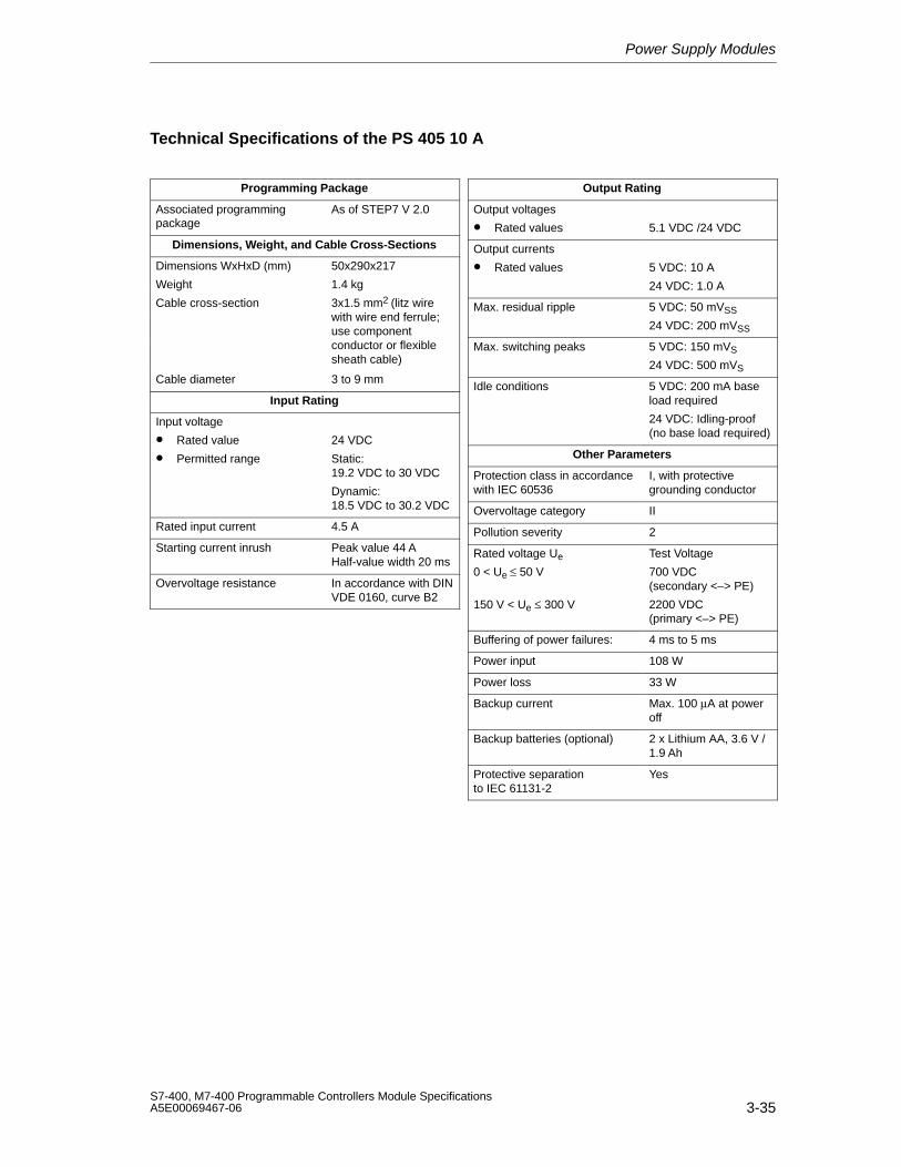
Power Supply Modules
3-35S7-400, M7-400 Programmable Controllers Module SpecificationsA5E00069467-06
Technical Specifications of the PS 405 10 A
Programming Package
Associated programmingpackage
As of STEP7 V 2.0
Dimensions, Weight, and Cable Cross-Sections
Dimensions WxHxD (mm) 50x290x217
Weight
Cable cross-section
1.4 kg
3x1.5 mm2 (litz wirewith wire end ferrule; use componentconductor or flexiblesheath cable)
Cable diameter 3 to 9 mm
Input Rating
Input voltage
• Rated value
• Permitted range
24 VDC
Static:19.2 VDC to 30 VDC
Dynamic:18.5 VDC to 30.2 VDC
Rated input current 4.5 A
Starting current inrush Peak value 44 AHalf-value width 20 ms
Overvoltage resistance In accordance with DINVDE 0160, curve B2
Output Rating
Output voltages
• Rated values 5.1 VDC /24 VDC
Output currents
• Rated values 5 VDC: 10 A
24 VDC: 1.0 A
Max. residual ripple 5 VDC: 50 mVSS
24 VDC: 200 mVSS
Max. switching peaks 5 VDC: 150 mVS
24 VDC: 500 mVS
Idle conditions 5 VDC: 200 mA baseload required
24 VDC: Idling-proof(no base load required)
Other Parameters
Protection class in accordancewith IEC 60536
I, with protectivegrounding conductor
Overvoltage category II
Pollution severity 2
Rated voltage Ue
0 < Ue ≤ 50 V
150 V < Ue ≤ 300 V
Test Voltage
700 VDC(secondary <–> PE)
2200 VDC(primary <–> PE)
Buffering of power failures: 4 ms to 5 ms
Power input 108 W
Power loss 33 W
Backup current Max. 100 µA at poweroff
Backup batteries (optional) 2 x Lithium AA, 3.6 V /1.9 Ah
Protective separationto IEC 61131-2
Yes
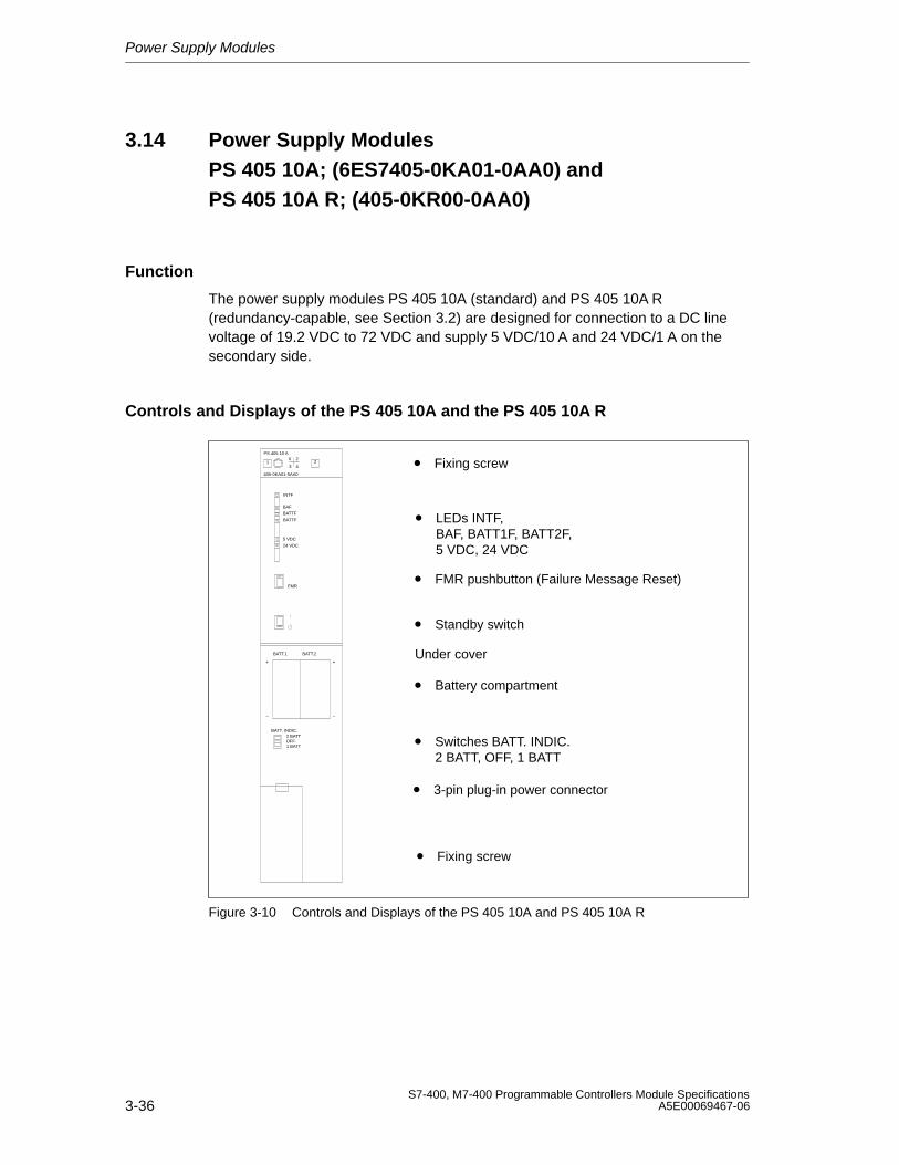
Power Supply Modules
3-36S7-400, M7-400 Programmable Controllers Module Specifications
A5E00069467-06
3.14 Power Supply Modules PS 405 10A; (6ES7405-0KA01-0AA0) and PS 405 10A R; (405-0KR00-0AA0)
Function
The power supply modules PS 405 10A (standard) and PS 405 10A R (redundancy-capable, see Section 3.2) are designed for connection to a DC linevoltage of 19.2 VDC to 72 VDC and supply 5 VDC/10 A and 24 VDC/1 A on thesecondary side.
Controls and Displays of the PS 405 10A and the PS 405 10A R
• LEDs INTF, BAF, BATT1F, BATT2F, 5 VDC, 24 VDC
• FMR pushbutton (Failure Message Reset)
• Standby switch
• Switches BATT. INDIC.2 BATT, OFF, 1 BATT
• Battery compartment
• Fixing screw
• 3-pin plug-in power connector
PS 405 10 A
405-0KA01-0AA0
X 2
3 41
FMR
2
INTF
BAF
BATTF
5 VDC
24 VDC
BATTF
BATT. INDIC.2 BATT
1 BATTOFF
BATT.1 BATT.2
+
–
+
–
Under cover
• Fixing screw
Figure 3-10 Controls and Displays of the PS 405 10A and PS 405 10A R
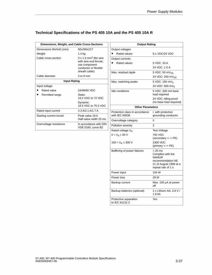
Power Supply Modules
3-37S7-400, M7-400 Programmable Controllers Module SpecificationsA5E00069467-06
Technical Specifications of the PS 405 10A and the PS 405 10A R
Dimensions, Weight, and Cable Cross-Sections
Dimensions WxHxD (mm) 50x290x217
Weight
Cable cross-section
1.4 kg
3 x 1.5 mm2 (litz wirewith wire end ferrule,use componentconductor or flexiblesheath cable)
Cable diameter 3 to 9 mm
Input Rating
Input voltage
• Rated value
• Permitted range
24/48/60 VDC
Static:19.2 VDC to 72 VDC
Dynamic:18.5 VDC to 75.5 VDC
Rated input current 4.3 A/2.1 A/1.7 A
Starting current inrush Peak value 18 AHalf-value width 20 ms
Overvoltage resistance In accordance with DINVDE 0160, curve B2
Output Rating
Output voltages
• Rated values 5.1 VDC/24 VDC
Output currents
• Rated values 5 VDC: 10 A
24 VDC: 1.0 A
Max. residual ripple 5 VDC: 50 mVSS
24 VDC: 200 mVSS
Max. switching peaks 5 VDC: 150 mVS
24 VDC: 500 mVS
Idle conditions 5 VDC: 200 mA baseload required
24 VDC: Idling-proof(no base load required)
Other Parameters
Protection class in accordancewith IEC 60536
I, with protectivegrounding conductor
Overvoltage category II
Pollution severity 2
Rated voltage Ue
0 < Ue ≤ 50 V
150 < Ue ≤ 300 V
Test Voltage
700 VDC(secondary <–> PE)
2300 VDC(primary <–> PE)
Buffering of power failures: > 20 msComplies with theNAMURrecommendation NE21 of August 1998 at arepeat rate of 1 s
Power input 104 W
Power loss 29 W
Backup current Max. 100 µA at poweroff
Backup batteries (optional) 2 x Lithium AA, 3.6 V /1.9 Ah
Protective separationto IEC 61131-2
Yes
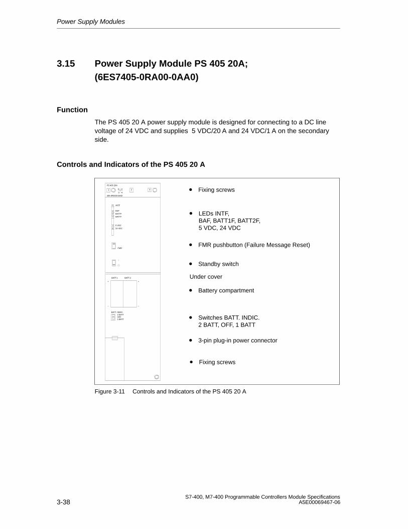
Power Supply Modules
3-38S7-400, M7-400 Programmable Controllers Module Specifications
A5E00069467-06
3.15 Power Supply Module PS 405 20A;(6ES7405-0RA00-0AA0)
Function
The PS 405 20 A power supply module is designed for connecting to a DC linevoltage of 24 VDC and supplies 5 VDC/20 A and 24 VDC/1 A on the secondaryside.
Controls and Indicators of the PS 405 20 A
• FMR pushbutton (Failure Message Reset)
• Standby switch
• Switches BATT. INDIC.2 BATT, OFF, 1 BATT
• Battery compartment
• Fixing screws
• 3-pin plug-in power connector
• LEDs INTF, BAF, BATT1F, BATT2F, 5 VDC, 24 VDC
PS 405 20A
405-0RA00-0AA0
X 2
3 41
FMR
2 3
INTF
BAF
BATTF
5 VDC
24 VDC
BATTF
BATT. INDIC.2 BATT
1 BATTOFF
BATT.1 BATT.2
+
–
+
–
Under cover
• Fixing screws
Figure 3-11 Controls and Indicators of the PS 405 20 A

Power Supply Modules
3-39S7-400, M7-400 Programmable Controllers Module SpecificationsA5E00069467-06
Technical Specifications of the PS 405 20 A
Programming Package
Associated programmingpackage
As of STEP7 V 2.0
Dimensions, Weight, and Cable Cross-Sections
Dimensions WxHxD (mm) 75x290x217
Weight
Cable cross-section
2.2 kg
3x1.5 mm2 (litz wirewith wire end ferrule;use componentconductor or flexiblesheath cable)
Cable diameter 3 to 9 mm
Input Rating
Input voltage
• Rated value
• Permitted range
24 VDC
Static:19.2 VDC to 30 VDC
Dynamic:18.5 VDC to 30.2 VDC
Rated input current 7.2 A
Starting current inrush Peak value 48 AHalf-value width 25 ms
Overvoltage resistance In accordance with DINVDE 0160, curve B2
Output Rating
Output voltages
• Rated values 5.1 VDC/24 VDC
Output currents
• Rated values 5 VDC: 20 A
24 VDC: 1.0 A
Max. residual ripple 5 VDC: 50 mVSS
24 VDC: 200 mVSS
Max. switching peaks 5 VDC: 150 mVS
24 VDC: 500 mVS
Idle conditions 5 VDC: 200 mA baseload required
24 VDC: Idling-proof(no base load required)
Other Parameters
Protection class in accordancewith IEC 60536
I, with protectivegrounding conductor
Overvoltage category II
Pollution severity 2
Rated voltage Ue
0 < Ue ≤ 50 V
150 V < Ue ≤ 300 V
Test Voltage
700 VDC(secondary <–> PE)
2200 VDC(primary <–> PE)
Buffering of power failures: 4 ms to 5 ms
Power input 172.8 W
Power loss 46.8 W
Backup current Max. 100 µA at poweroff
Backup batteries (optional) 2 x Lithium AA, 3.6 V /1.9 Ah
Protective separationto IEC 61131-2
Yes
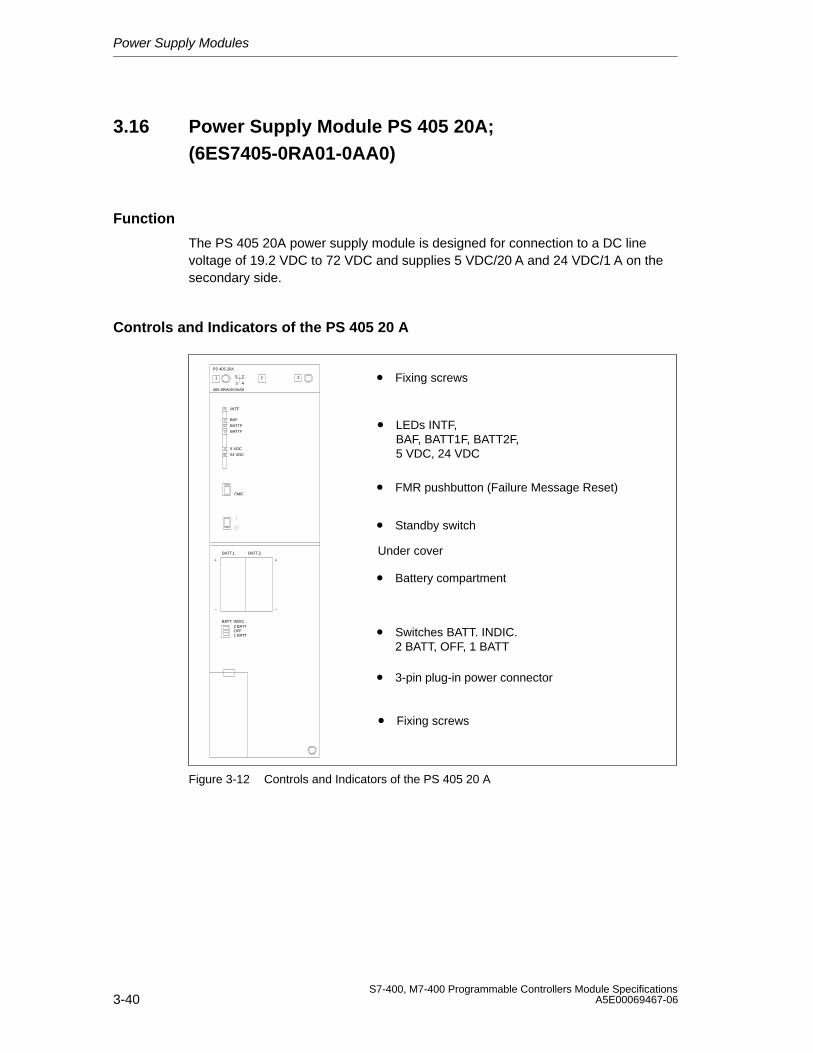
Power Supply Modules
3-40S7-400, M7-400 Programmable Controllers Module Specifications
A5E00069467-06
3.16 Power Supply Module PS 405 20A;(6ES7405-0RA01-0AA0)
Function
The PS 405 20A power supply module is designed for connection to a DC linevoltage of 19.2 VDC to 72 VDC and supplies 5 VDC/20 A and 24 VDC/1 A on thesecondary side.
Controls and Indicators of the PS 405 20 A
• FMR pushbutton (Failure Message Reset)
• Standby switch
• Switches BATT. INDIC.2 BATT, OFF, 1 BATT
• Battery compartment
• Fixing screws
• 3-pin plug-in power connector
• LEDs INTF, BAF, BATT1F, BATT2F, 5 VDC, 24 VDC
PS 405 20A
405-0RA00-0AA0
X 2
3 41
FMR
2 3
INTF
BAF
BATTF
5 VDC
24 VDC
BATTF
BATT. INDIC.2 BATT
1 BATTOFF
BATT.1 BATT.2
+
–
+
–
Under cover
• Fixing screws
Figure 3-12 Controls and Indicators of the PS 405 20 A
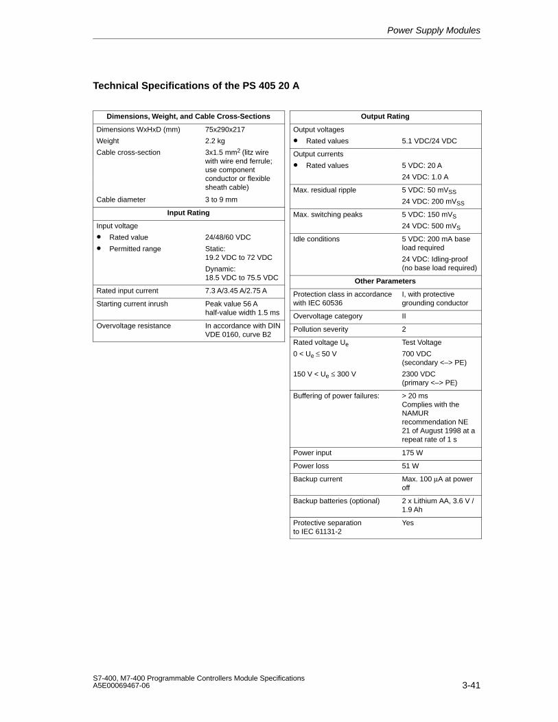
Power Supply Modules
3-41S7-400, M7-400 Programmable Controllers Module SpecificationsA5E00069467-06
Technical Specifications of the PS 405 20 A
Dimensions, Weight, and Cable Cross-Sections
Dimensions WxHxD (mm) 75x290x217
Weight
Cable cross-section
2.2 kg
3x1.5 mm2 (litz wirewith wire end ferrule;use componentconductor or flexiblesheath cable)
Cable diameter 3 to 9 mm
Input Rating
Input voltage
• Rated value
• Permitted range
24/48/60 VDC
Static:19.2 VDC to 72 VDC
Dynamic:18.5 VDC to 75.5 VDC
Rated input current 7.3 A/3.45 A/2.75 A
Starting current inrush Peak value 56 Ahalf-value width 1.5 ms
Overvoltage resistance In accordance with DINVDE 0160, curve B2
Output Rating
Output voltages
• Rated values 5.1 VDC/24 VDC
Output currents
• Rated values 5 VDC: 20 A
24 VDC: 1.0 A
Max. residual ripple 5 VDC: 50 mVSS
24 VDC: 200 mVSS
Max. switching peaks 5 VDC: 150 mVS
24 VDC: 500 mVS
Idle conditions 5 VDC: 200 mA baseload required
24 VDC: Idling-proof(no base load required)
Other Parameters
Protection class in accordancewith IEC 60536
I, with protectivegrounding conductor
Overvoltage category II
Pollution severity 2
Rated voltage Ue
0 < Ue ≤ 50 V
150 V < Ue ≤ 300 V
Test Voltage
700 VDC(secondary <–> PE)
2300 VDC(primary <–> PE)
Buffering of power failures: > 20 msComplies with theNAMURrecommendation NE21 of August 1998 at arepeat rate of 1 s
Power input 175 W
Power loss 51 W
Backup current Max. 100 µA at poweroff
Backup batteries (optional) 2 x Lithium AA, 3.6 V /1.9 Ah
Protective separationto IEC 61131-2
Yes

Power Supply Modules
3-42S7-400, M7-400 Programmable Controllers Module Specifications
A5E00069467-06
4-1S7-400, M7-400 Programmable Controllers Module SpecificationsA5E00069467-06
Digital Modules
Structure of the Chapter
The present chapter is subdivided into the following subjects:
1. Overview containing the modules that are available here and a description
2. Information that is generally valid – in other words, relating to all digital modules(for example, parameter assignment and diagnostics)
3. Information that refers to specific modules (for example, characteristics,diagram of connections and block diagram, technical specifications and specialcharacteristics of the module):
a) for digital input modules
b) for digital output modules
Additional Information
Appendix A describes the structure of the parameter records (data records 0, 1 and128) in the system data. You must be familiar with this structure if you want tomodify the parameters of the modules in the STEP 7 user program.
Appendix B describes the structure of the diagnostic data (data records 0, 1) in thesystem data. You must be familiar with this structure if you want to evaluate thediagnostic data of the modules in the STEP 7 user program.
4
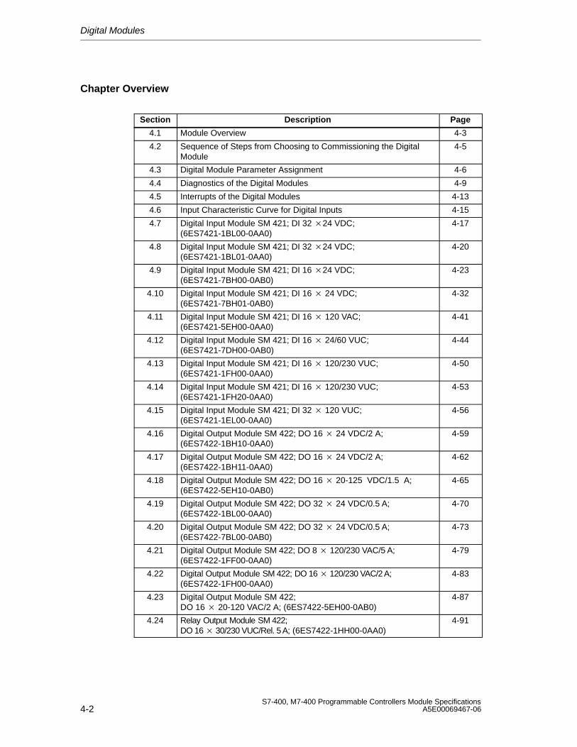
Digital Modules
4-2S7-400, M7-400 Programmable Controllers Module Specifications
A5E00069467-06
Chapter Overview
Section Description Page
4.1 Module Overview 4-3
4.2 Sequence of Steps from Choosing to Commissioning the DigitalModule
4-5
4.3 Digital Module Parameter Assignment 4-6
4.4 Diagnostics of the Digital Modules 4-9
4.5 Interrupts of the Digital Modules 4-13
4.6 Input Characteristic Curve for Digital Inputs 4-15
4.7 Digital Input Module SM 421; DI 32 24 VDC;(6ES7421-1BL00-0AA0)
4-17
4.8 Digital Input Module SM 421; DI 32 24 VDC;(6ES7421-1BL01-0AA0)
4-20
4.9 Digital Input Module SM 421; DI 16 24 VDC;(6ES7421-7BH00-0AB0)
4-23
4.10 Digital Input Module SM 421; DI 16 24 VDC;(6ES7421-7BH01-0AB0)
4-32
4.11 Digital Input Module SM 421; DI 16 120 VAC;(6ES7421-5EH00-0AA0)
4-41
4.12 Digital Input Module SM 421; DI 16 24/60 VUC;(6ES7421-7DH00-0AB0)
4-44
4.13 Digital Input Module SM 421; DI 16 120/230 VUC;(6ES7421-1FH00-0AA0)
4-50
4.14 Digital Input Module SM 421; DI 16 120/230 VUC;(6ES7421-1FH20-0AA0)
4-53
4.15 Digital Input Module SM 421; DI 32 120 VUC;(6ES7421-1EL00-0AA0)
4-56
4.16 Digital Output Module SM 422; DO 16 24 VDC/2 A;(6ES7422-1BH10-0AA0)
4-59
4.17 Digital Output Module SM 422; DO 16 24 VDC/2 A;(6ES7422-1BH11-0AA0)
4-62
4.18 Digital Output Module SM 422; DO 16 20-125 VDC/1.5 A;(6ES7422-5EH10-0AB0)
4-65
4.19 Digital Output Module SM 422; DO 32 24 VDC/0.5 A;(6ES7422-1BL00-0AA0)
4-70
4.20 Digital Output Module SM 422; DO 32 24 VDC/0.5 A;(6ES7422-7BL00-0AB0)
4-73
4.21 Digital Output Module SM 422; DO 8 120/230 VAC/5 A;(6ES7422-1FF00-0AA0)
4-79
4.22 Digital Output Module SM 422; DO 16 120/230 VAC/2 A;(6ES7422-1FH00-0AA0)
4-83
4.23 Digital Output Module SM 422;DO 16 20-120 VAC/2 A; (6ES7422-5EH00-0AB0)
4-87
4.24 Relay Output Module SM 422;DO 16 30/230 VUC/Rel. 5 A; (6ES7422-1HH00-0AA0)
4-91
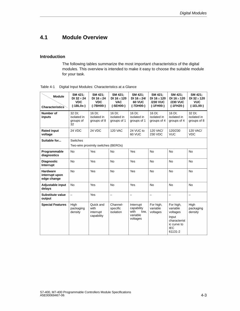
Digital Modules
4-3S7-400, M7-400 Programmable Controllers Module SpecificationsA5E00069467-06
4.1 Module Overview
Introduction
The following tables summarize the most important characteristics of the digitalmodules. This overview is intended to make it easy to choose the suitable modulefor your task.
Table 4-1 Digital Input Modules: Characteristics at a Glance
Module
Characteristics
SM 421; DI 3224
VDC(-1BL0x-)
SM 421; DI 1624
VDC(-7BH00-)
SM 421; DI 16120
VAC(-5EH00-)
SM 421; DI 1624/
60 VUC(-7DH00-)
SM 421; DI 16120/230 VUC(-1FH00-)
SM 421; DI 16120/230 VUC(-1FH20-)
SM 421; DI 32120
VUC(-1EL00-)
Number ofinputs
32 DI;isolated ingroups of32
16 DI;isolated ingroups of 8
16 DI;isolated ingroups of 1
16 DI;isolated ingroups of 1
16 DI;isolated ingroups of 4
16 DI;isolated ingroups of 4
32 DI;isolated ingroups of 8
Rated inputvoltage
24 VDC 24 VDC 120 VAC 24 VUC to60 VUC
120 VAC/230 VDC
120/230VUC
120 VAC/VDC
Suitable for... Switches
Two-wire proximity switches (BEROs)
Programmablediagnostics
No Yes No Yes No No No
DiagnosticInterrupt
No Yes No Yes No No No
Hardwareinterrupt uponedge change
No Yes No Yes No No No
Adjustable inputdelays
No Yes No Yes No No No
Substitute valueoutput
– Yes – – – – –
Special Features Highpackagingdensity
Quick andwithinterruptcapability
Channel-specificisolation
Interruptcapabilitywith low,variablevoltages
For high, variablevoltages
For high, variablevoltages
Inputcharacteristic curve toIEC61131-2
Highpackagingdensity
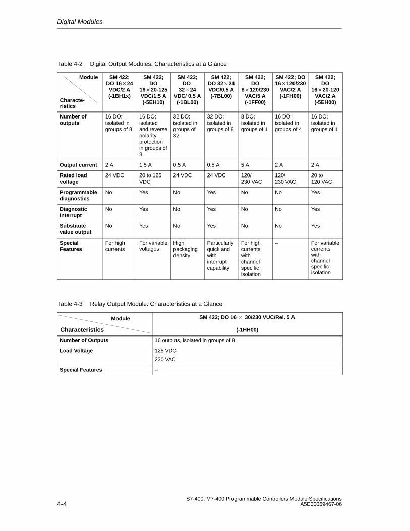
Digital Modules
4-4S7-400, M7-400 Programmable Controllers Module Specifications
A5E00069467-06
Table 4-2 Digital Output Modules: Characteristics at a Glance
Module
Characte-ristics
SM 422;DO 1624VDC/2 A(-1BH1x)
SM 422;DO
1620-125VDC/1.5 A(-5EH10)
SM 422;DO
3224VDC/ 0.5 A(-1BL00)
SM 422;DO 3224VDC/0.5 A(-7BL00)
SM 422;DO
8120/230VAC/5 A(-1FF00)
SM 422; DO16120/230
VAC/2 A(-1FH00)
SM 422;DO
1620-120VAC/2 A(-5EH00)
Number ofoutputs
16 DO;isolated ingroups of 8
16 DO;isolatedand reversepolarityprotectionin groups of8
32 DO;isolated ingroups of32
32 DO; isolated ingroups of 8
8 DO;isolated ingroups of 1
16 DO;isolated ingroups of 4
16 DO; isolated ingroups of 1
Output current 2 A 1.5 A 0.5 A 0.5 A 5 A 2 A 2 A
Rated loadvoltage
24 VDC 20 to 125VDC
24 VDC 24 VDC 120/230 VAC
120/230 VAC
20 to 120 VAC
Programmablediagnostics
No Yes No Yes No No Yes
DiagnosticInterrupt
No Yes No Yes No No Yes
Substitutevalue output
No Yes No Yes No No Yes
SpecialFeatures
For highcurrents
For variablevoltages
Highpackagingdensity
Particularlyquick andwithinterruptcapability
For highcurrentswithchannel-specificisolation
– For variablecurrentswithchannel-specificisolation
Table 4-3 Relay Output Module: Characteristics at a Glance
Module
Characteristics
SM 422; DO 16 30/230 VUC/Rel. 5 A
(-1HH00)
Number of Outputs 16 outputs, isolated in groups of 8
Load Voltage 125 VDC
230 VAC
Special Features –
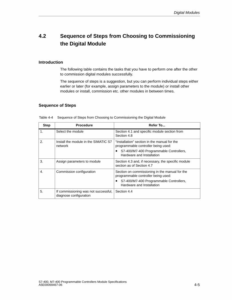
Digital Modules
4-5S7-400, M7-400 Programmable Controllers Module SpecificationsA5E00069467-06
4.2 Sequence of Steps from Choosing to Commissioningthe Digital Module
Introduction
The following table contains the tasks that you have to perform one after the otherto commission digital modules successfully.
The sequence of steps is a suggestion, but you can perform individual steps eitherearlier or later (for example, assign parameters to the module) or install othermodules or install, commission etc. other modules in between times.
Sequence of Steps
Table 4-4 Sequence of Steps from Choosing to Commissioning the Digital Module
Step Procedure Refer To...
1. Select the module Section 4.1 and specific module section fromSection 4.8
2. Install the module in the SIMATIC S7network
“Installation” section in the manual for theprogrammable controller being used:
• S7-400/M7-400 Programmable Controllers,Hardware and Installation
3. Assign parameters to module Section 4.3 and, if necessary, the specific modulesection as of Section 4.7
4. Commission configuration Section on commissioning in the manual for theprogrammable controller being used:
• S7-400/M7-400 Programmable Controllers,Hardware and Installation
5. If commissioning was not successful,diagnose configuration
Section 4.4
Digital Modules
4-6S7-400, M7-400 Programmable Controllers Module Specifications
A5E00069467-06
4.3 Digital Module Parameter Assignment
Introduction
Digital modules can have different characteristics. You can set the characteristicsof dome modules by means of parameter assignment.
Tools for Parameter Assignment
You assign parameters to digital modules in STEP 7. You must perform parameterassignment in STOP mode of the CPU.
When you have set all the parameters, download the parameters from theprogramming device to the CPU. When there is a transition from STOP to RUNmode, the CPU transfers the parameters to the individual digital modules.
Static and dynamic parameters
The parameters are divided into static and dynamic parameters.
Set the static parameters in STOP mode of the CPU, as described above.
In addition, you can modify the dynamic parameters in the current user program inan S7 programmable controller by means of SFCs. Note, however, that after achange from RUN STOP, STOP RUN of the CPU, the parameters set inSTEP 7 apply again. You will find a description of the parameter assignment ofmodules in the user program in Appendix A.
Table 4-5 Static and dynamic parameters of the digital modules
Parameter Settable with CPU OperatingMode
Static PG (STEP 7 HWCONFIG) STOP
Dynamic PG (STEP 7 HWCONFIG) STOP
SFC 55 in the user program RUN
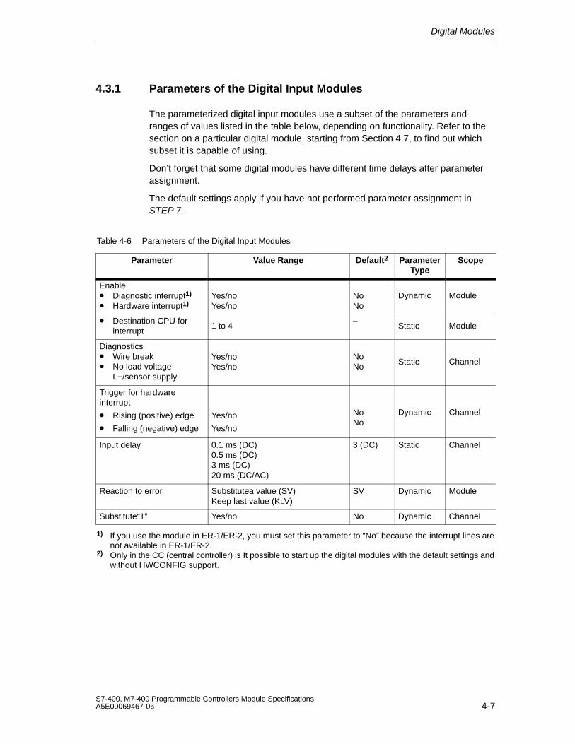
Digital Modules
4-7S7-400, M7-400 Programmable Controllers Module SpecificationsA5E00069467-06
4.3.1 Parameters of the Digital Input Modules
The parameterized digital input modules use a subset of the parameters andranges of values listed in the table below, depending on functionality. Refer to thesection on a particular digital module, starting from Section 4.7, to find out whichsubset it is capable of using.
Don’t forget that some digital modules have different time delays after parameterassignment.
The default settings apply if you have not performed parameter assignment inSTEP 7.
Table 4-6 Parameters of the Digital Input Modules
Parameter Value Range Default2 ParameterType
Scope
Enable• Diagnostic interrupt1)
• Hardware interrupt1)Yes/noYes/no
NoNo
Dynamic Module
• Destination CPU forinterrupt
1 to 4–
Static Module
Diagnostics• Wire break• No load voltage
L+/sensor supply
Yes/noYes/no
NoNo Static Channel
Trigger for hardwareinterrupt
• Rising (positive) edge
• Falling (negative) edge
Yes/no
Yes/no
NoNo
Dynamic Channel
Input delay 0.1 ms (DC)0.5 ms (DC)3 ms (DC)20 ms (DC/AC)
3 (DC) Static Channel
Reaction to error Substitutea value (SV)Keep last value (KLV)
SV Dynamic Module
Substitute“1” Yes/no No Dynamic Channel
1) If you use the module in ER-1/ER-2, you must set this parameter to “No” because the interrupt lines arenot available in ER-1/ER-2.
2) Only in the CC (central controller) is It possible to start up the digital modules with the default settings andwithout HWCONFIG support.
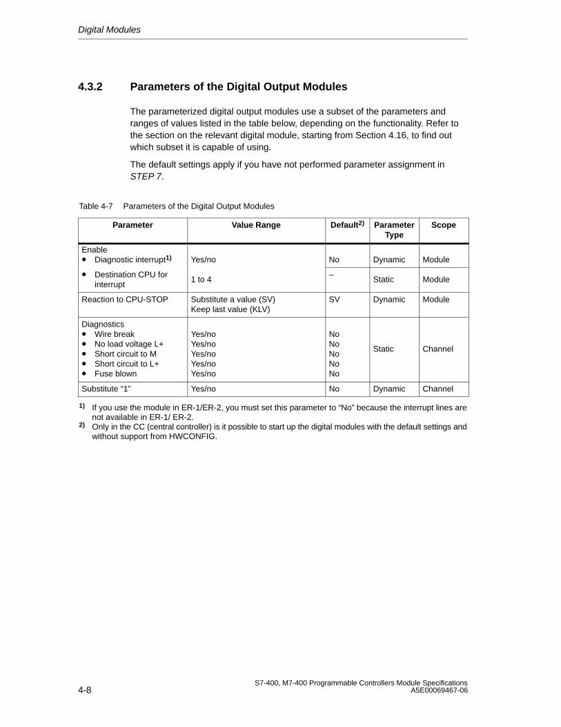
Digital Modules
4-8S7-400, M7-400 Programmable Controllers Module Specifications
A5E00069467-06
4.3.2 Parameters of the Digital Output Modules
The parameterized digital output modules use a subset of the parameters andranges of values listed in the table below, depending on the functionality. Refer tothe section on the relevant digital module, starting from Section 4.16, to find outwhich subset it is capable of using.
The default settings apply if you have not performed parameter assignment inSTEP 7.
Table 4-7 Parameters of the Digital Output Modules
Parameter Value Range Default2) ParameterType
Scope
Enable• Diagnostic interrupt1) Yes/no No Dynamic Module
• Destination CPU forinterrupt
1 to 4–
Static Module
Reaction to CPU-STOP Substitute a value (SV)Keep last value (KLV)
SV Dynamic Module
Diagnostics• Wire break • No load voltage L+ • Short circuit to M • Short circuit to L+ • Fuse blown
Yes/noYes/noYes/noYes/noYes/no
NoNoNoNoNo
Static Channel
Substitute “1” Yes/no No Dynamic Channel
1) If you use the module in ER-1/ER-2, you must set this parameter to “No” because the interrupt lines arenot available in ER-1/ ER-2.
2) Only in the CC (central controller) is it possible to start up the digital modules with the default settings andwithout support from HWCONFIG.
Digital Modules
4-9S7-400, M7-400 Programmable Controllers Module SpecificationsA5E00069467-06
4.4 Diagnostics of the Digital Modules
Programmable and Non-Programmable Diagnostic Messages
In diagnostics, we make a distinction between programmable andnon-programmable diagnostic messages.
You obtain programmable diagnostic messages only if you have enableddiagnostics by parameter assignment. You perform parameter assignment in the”Diagnostics” parameter block in STEP 7 (refer to Section 5.7).
Non-programmable diagnostic messages are always made available by the digitalmodule irrespective of diagnostics being enabled.
Actions Following Diagnostic Message in STEP 7
Each diagnostic message leads to the following actions:
• The diagnostic message is entered in the diagnostics of the digital module,forwarded to the CPU and can be read out by the user program.
• The fault LED on the digital module lights up.
• If you have parameterized “Enable Diagnostic Interrupt” in STEP 7, a diagnosticinterrupt is triggered and OB 82 is called (refer to Section 4.5).
Reading Out Diagnostic Messages
You can read out detailed diagnostic messages by means of SFCs in the userprogram (refer to the Appendix “Diagnostic Data of Signal Modules”).
You can view the cause of the error in STEP 7 in the module diagnosis (refer to the STEP 7 online help system).
Diagnostics Using the INTF and EXTF LEDs
Some digital modules indicate faults by means of their two fault LEDs INTF(internal fault) and EXTF (external fault). The LEDs go out when all the internal andexternal faults have been eliminated.
Refer to the technical specifications of the modules, starting at Section 4.7, to findout which digital modules have these fault LEDs.
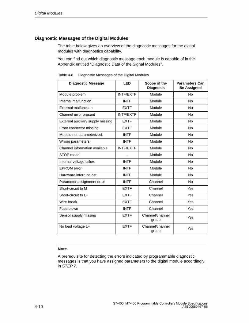
Digital Modules
4-10S7-400, M7-400 Programmable Controllers Module Specifications
A5E00069467-06
Diagnostic Messages of the Digital Modules
The table below gives an overview of the diagnostic messages for the digitalmodules with diagnostics capability.
You can find out which diagnostic message each module is capable of in theAppendix entitled “Diagnostic Data of the Signal Modules”.
Table 4-8 Diagnostic Messages of the Digital Modules
Diagnostic Message LED Scope of theDiagnosis
Parameters CanBe Assigned
Module problem INTF/EXTF Module No
Internal malfunction INTF Module No
External malfunction EXTF Module No
Channel error present INTF/EXTF Module No
External auxiliary supply missing EXTF Module No
Front connector missing EXTF Module No
Module not parameterized. INTF Module No
Wrong parameters INTF Module No
Channel information available INTF/EXTF Module No
STOP mode – Module No
Internal voltage failure INTF Module No
EPROM error INTF Module No
Hardware interrupt lost INTF Module No
Parameter assignment error INTF Channel No
Short-circuit to M EXTF Channel Yes
Short-circuit to L+ EXTF Channel Yes
Wire break EXTF Channel Yes
Fuse blown INTF Channel Yes
Sensor supply missing EXTF Channel/channelgroup
Yes
No load voltage L+ EXTF Channel/channelgroup
Yes
Note
A prerequisite for detecting the errors indicated by programmable diagnosticmessages is that you have assigned parameters to the digital module accordinglyin STEP 7.
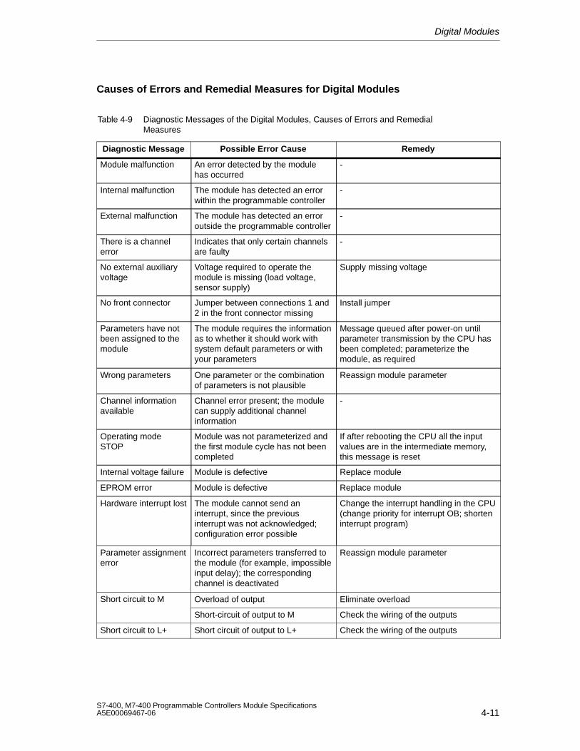
Digital Modules
4-11S7-400, M7-400 Programmable Controllers Module SpecificationsA5E00069467-06
Causes of Errors and Remedial Measures for Digital Modules
Table 4-9 Diagnostic Messages of the Digital Modules, Causes of Errors and RemedialMeasures
Diagnostic Message Possible Error Cause Remedy
Module malfunction An error detected by the modulehas occurred
-
Internal malfunction The module has detected an errorwithin the programmable controller
-
External malfunction The module has detected an erroroutside the programmable controller
-
There is a channelerror
Indicates that only certain channelsare faulty
-
No external auxiliaryvoltage
Voltage required to operate themodule is missing (load voltage,sensor supply)
Supply missing voltage
No front connector Jumper between connections 1 and2 in the front connector missing
Install jumper
Parameters have notbeen assigned to themodule
The module requires the informationas to whether it should work withsystem default parameters or withyour parameters
Message queued after power-on untilparameter transmission by the CPU hasbeen completed; parameterize themodule, as required
Wrong parameters One parameter or the combinationof parameters is not plausible
Reassign module parameter
Channel informationavailable
Channel error present; the modulecan supply additional channelinformation
-
Operating modeSTOP
Module was not parameterized andthe first module cycle has not beencompleted
If after rebooting the CPU all the inputvalues are in the intermediate memory,this message is reset
Internal voltage failure Module is defective Replace module
EPROM error Module is defective Replace module
Hardware interrupt lost The module cannot send aninterrupt, since the previousinterrupt was not acknowledged;configuration error possible
Change the interrupt handling in the CPU(change priority for interrupt OB; shorteninterrupt program)
Parameter assignmenterror
Incorrect parameters transferred tothe module (for example, impossibleinput delay); the correspondingchannel is deactivated
Reassign module parameter
Short circuit to M Overload of output Eliminate overload
Short-circuit of output to M Check the wiring of the outputs
Short circuit to L+ Short circuit of output to L+ Check the wiring of the outputs
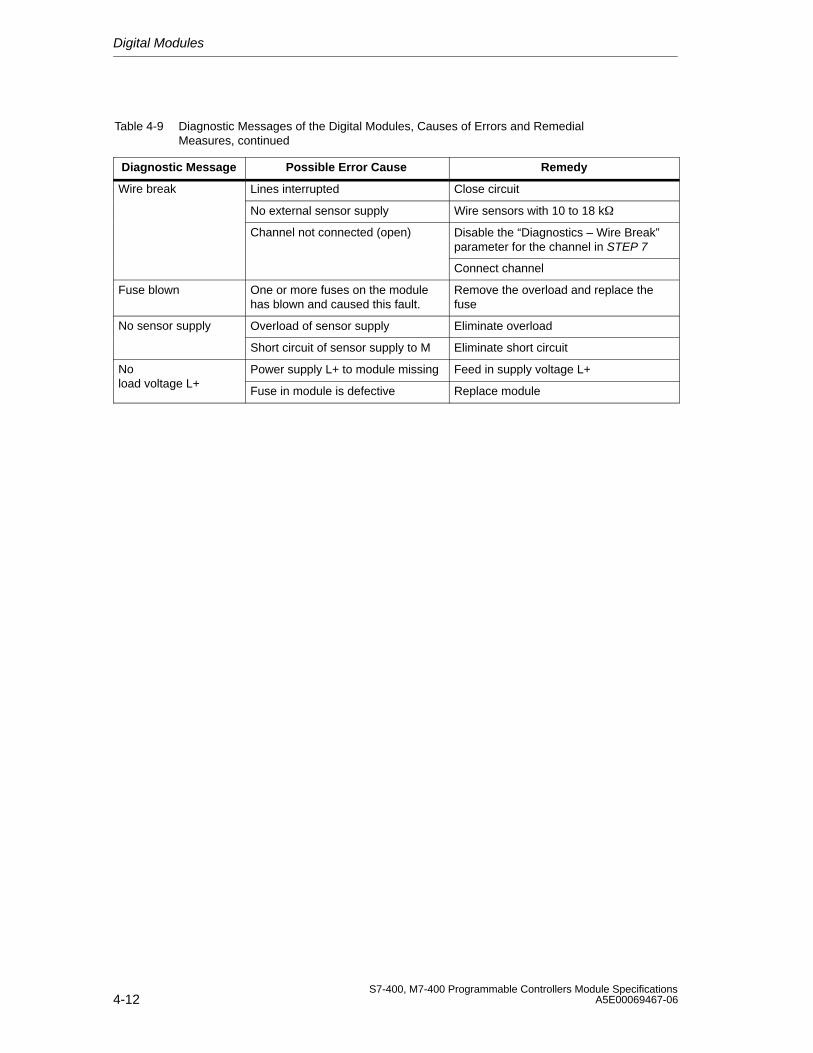
Digital Modules
4-12S7-400, M7-400 Programmable Controllers Module Specifications
A5E00069467-06
Table 4-9 Diagnostic Messages of the Digital Modules, Causes of Errors and RemedialMeasures, continued
Diagnostic Message RemedyPossible Error Cause
Wire break Lines interrupted Close circuit
No external sensor supply Wire sensors with 10 to 18 k
Channel not connected (open) Disable the “Diagnostics – Wire Break”parameter for the channel in STEP 7
Connect channel
Fuse blown One or more fuses on the modulehas blown and caused this fault.
Remove the overload and replace thefuse
No sensor supply Overload of sensor supply Eliminate overload
Short circuit of sensor supply to M Eliminate short circuit
No Power supply L+ to module missing Feed in supply voltage L+load voltage L+
Fuse in module is defective Replace module
Digital Modules
4-13S7-400, M7-400 Programmable Controllers Module SpecificationsA5E00069467-06
4.5 Interrupts of the Digital Modules
Introduction
This section describes the interrupt behavior of the digital modules. The followinginterrupts exist:
• Diagnostic Interrupt
• Hardware interrupt
Note that not all digital modules have interrupt capability or they are only capable ofa subset of the interrupts described here. Refer to the technical specifications ofthe modules, starting at Section 4.7, to find out which digital modules have interruptcapability.
The OBs and SFCs mentioned below can be found in the online help system forSTEP 7, where they are described in greater detail.
Enabling Interrupts
The interrupts are not preset – in other words, they are inhibited withoutappropriate parameter assignment. You enable the interrupts in STEP 7 (refer to Section 5.7).
Special Feature: The Module is Inserted in ER-1/ER-2
Note
If you use the digital module in ER-1/ER-2, you must set the parameters forenabling all the interrupts to “No” because the interrupt lines are not available inER-1/ER-2.
Diagnostic Interrupt
If you have enabled diagnostic interrupts, then active error events (initialoccurrence of the error) and departing error events (message after troubleshooting)are reported by means of an interrupt.
The CPU interrupts the execution of the user program and processes thediagnostic interrupt block (OB 82).
In the user program, you can call SFC 51 or SFC 59 in OB 82 to obtain moredetailed diagnostic information from the module.
The diagnostic information is consistent until such time as OB 82 is exited. WhenOB 82 is exited, the diagnostic interrupt is acknowledged on the module.
Digital Modules
4-14S7-400, M7-400 Programmable Controllers Module Specifications
A5E00069467-06
Hardware Interrupt
A digital input module can trigger a hardware interrupt for each channel at a risingor falling edge, or both, of a signal status change.
You perform parameter assignment for each channel separately. It can be modifiedat any time (in RUN mode using the user program).
Pending hardware interrupts trigger hardware interrupt processing in the CPU(OB 40 to OB 47). The CPU interrupts the execution of the user program or of thepriority classes with low priority.
In the user program of the hardware interrupt OB (OB 40 to OB 47) you can specifyhow the programmable controller is to respond to an edge change. When thehardware interrupt OB is exited, the hardware interrupt is acknowledged on themodule.
For each channel the digital input module can buffer an interrupt that has not beentriggered. If no higher priority run-time levels are waiting to be processed, thebuffered interrupts (of all modules) are serviced one after the other by the CPUaccording to the order in which they occurred.
Hardware Interrupt Lost
In an interrupt has been buffered for a channel and another interrupt occurs on thatchannel before it has been processed by the CPU, a diagnostic interrupt “hardwareinterrupt lost” is triggered.
More interrupts on this channel are not acquired until processing of the interruptbuffered on this channel has been executed.
Interrupt-Triggering Channels
The interrupt-triggering channels are stored in the local data of the hardwareinterrupt OBs (in the start information of the corresponding OB). The startinformation is two words long (bits 0 to 31). The bit number is the channel number.Bits 16 to 31 are not assigned.
Digital Modules
4-15S7-400, M7-400 Programmable Controllers Module SpecificationsA5E00069467-06
4.6 Input Characteristic Curve for Digital Inputs
IEC 61131, Type 1 and Type 2
The IEC 61131 standard requires the following for the input current:
• In the case of type 2, an input current of 2 mA already at + 5 V
• In the case of type 1, an input current of 0.5 mA already at + 5 V
EN 60947-5-2, Two-Wire BEROs
The standard for BEROs (EN 60947-5-2) specifies that there can be a current of 1.5 mA for BEROs in the “0” signal state.
The input current of the module in the ”0” signal state is decisive for the operationof two-wire BEROs. This must be in accordance with BERO requirements.
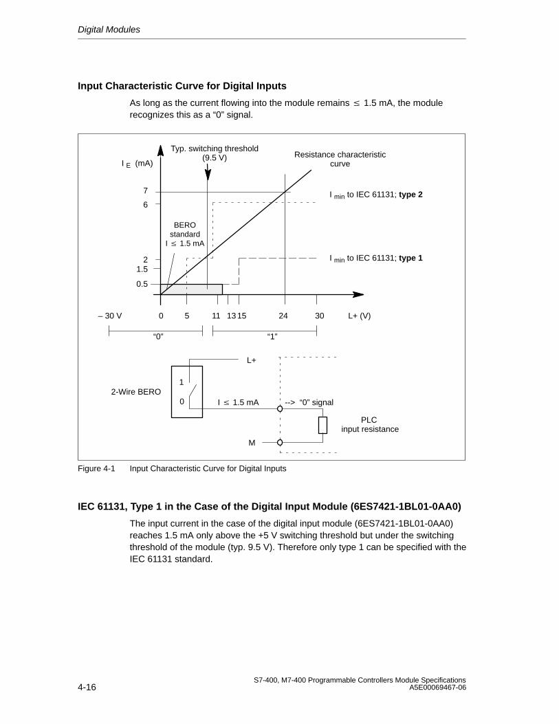
Digital Modules
4-16S7-400, M7-400 Programmable Controllers Module Specifications
A5E00069467-06
Input Characteristic Curve for Digital Inputs
As long as the current flowing into the module remains 1.5 mA, the modulerecognizes this as a “0” signal.
0.5
1.52
6
7
0 5 11 13 15 24 30
I min to IEC 61131; type 2
I min to IEC 61131; type 1
Typ. switching threshold(9.5 V) Resistance characteristic
curve
L+ (V)– 30 V
I E (mA)
“0” “1”
1
0
L+
M
I 1.5 mA --> “0” signal
PLC input resistance
2-Wire BERO
BEROstandard
I 1.5 mA
Figure 4-1 Input Characteristic Curve for Digital Inputs
IEC 61131, Type 1 in the Case of the Digital Input Module (6ES7421-1BL01-0AA0)
The input current in the case of the digital input module (6ES7421-1BL01-0AA0)reaches 1.5 mA only above the +5 V switching threshold but under the switchingthreshold of the module (typ. 9.5 V). Therefore only type 1 can be specified with theIEC 61131 standard.
Digital Modules
4-17S7-400, M7-400 Programmable Controllers Module SpecificationsA5E00069467-06
4.7 Digital Input Module SM 421; DI 32 24 VDC(6ES7421-1BL00-0AA0)
Characteristics
The SM 421;DI 32 x 24 VDC is a digital input module with the following features:
• 32 inputs, isolated in a group of 32. In other words, all inputs share the samechassis ground.
• Rated load voltage: 24 VDC
• Suitable for switches and 2-wire proximity switches (BEROs, IEC 61131; type 2).
The status LEDs indicate the process status.
Functional Expansion as of Version 03
The lower limit of the rated input range is increased at signal “0” from –3 to –30 V.
The rated input voltage for signal “0” is thus: –30 V to 5 V
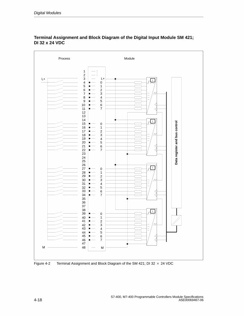
Digital Modules
4-18S7-400, M7-400 Programmable Controllers Module Specifications
A5E00069467-06
Terminal Assignment and Block Diagram of the Digital Input Module SM 421;DI 32 x 24 VDC
123456789
101112131415161718192021222324252627282930313233343536373839404142434445464748
1234567
L+0
M
1234567
0
1234567
0
1234567
0
M
L+
Process
t
t
t
t
Dat
a re
gis
ter
and
bu
s co
ntr
ol
Module
Figure 4-2 Terminal Assignment and Block Diagram of the SM 421; DI 32 24 VDC
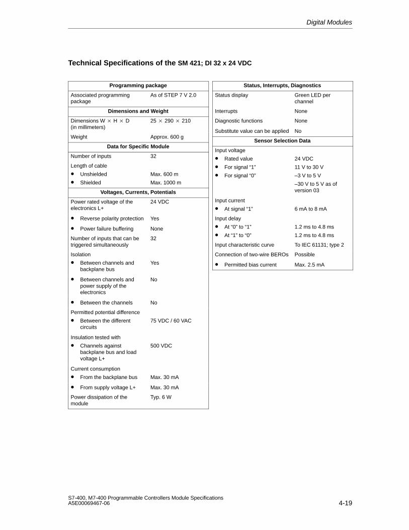
Digital Modules
4-19S7-400, M7-400 Programmable Controllers Module SpecificationsA5E00069467-06
Technical Specifications of the SM 421; DI 32 x 24 VDC
Programming package
Associated programmingpackage
As of STEP 7 V 2.0
Dimensions and Weight
Dimensions W H D(in millimeters)
25 290 210
Weight Approx. 600 g
Data for Specific Module
Number of inputs 32
Length of cable
• Unshielded
• Shielded
Max. 600 m
Max. 1000 m
Voltages, Currents, Potentials
Power rated voltage of theelectronics L+
24 VDC
• Reverse polarity protection Yes
• Power failure buffering None
Number of inputs that can betriggered simultaneously
32
Isolation
• Between channels andbackplane bus
Yes
• Between channels andpower supply of theelectronics
No
• Between the channels No
Permitted potential difference
• Between the differentcircuits
75 VDC / 60 VAC
Insulation tested with
• Channels againstbackplane bus and loadvoltage L+
500 VDC
Current consumption
• From the backplane bus Max. 30 mA
• From supply voltage L+ Max. 30 mA
Power dissipation of themodule
Typ. 6 W
Status, Interrupts, Diagnostics
Status display Green LED perchannel
Interrupts None
Diagnostic functions None
Substitute value can be applied No
Sensor Selection Data
Input voltage
• Rated value
• For signal “1”
• For signal “0”
24 VDC
11 V to 30 V
–3 V to 5 V
–30 V to 5 V as ofversion 03
Input current
• At signal “1” 6 mA to 8 mA
Input delay
• At “0” to “1”
• At “1” to “0”
1.2 ms to 4.8 ms
1.2 ms to 4.8 ms
Input characteristic curve To IEC 61131; type 2
Connection of two-wire BEROs Possible
• Permitted bias current Max. 2.5 mA
Digital Modules
4-20S7-400, M7-400 Programmable Controllers Module Specifications
A5E00069467-06
4.8 Digital Input Module SM 421; DI 32 24 VDC;(6ES7421-1BL01-0AA0)
Characteristics
The digital input module SM 421; DI 32 24 VDC has the following features:
• 32 inputs, isolated in a group of 32
• 24 VDC rated input voltage
• Suitable for switches and two/three/four-wire proximity switches (BEROs, IEC 61131; type 1)
The status LEDs indicate the process status.
Notice
If you use the module with the order number 6ES7421-1BL01-0AA0 as areplacement for the module with the order number 6ES7421-1BL00-0AA0, you canleave PIN 3 wired. If you run modules 6ES7421-1BL00-0AA0 and6ES7421-1BL01-0AA0 involved in mutual exchange, you have to wire and supplyPIN 3 as described in Section 4.7.
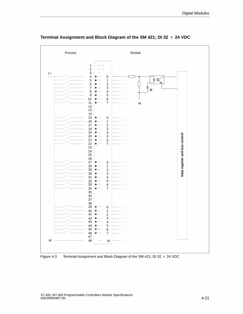
Digital Modules
4-21S7-400, M7-400 Programmable Controllers Module SpecificationsA5E00069467-06
Terminal Assignment and Block Diagram of the SM 421; DI 32 24 VDC
123456789
101112131415161718192021222324252627282930313233343536373839404142434445464748
1234567
0
M
1234567
0
1234567
0
1234567
0
M
L+
Process
Dat
a re
gis
ter
and
bu
s co
ntr
ol
Module
M
Figure 4-3 Terminal Assignment and Block Diagram of the SM 421; DI 32 24 VDC
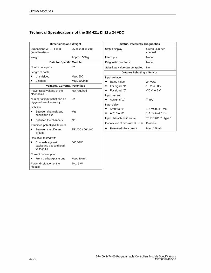
Digital Modules
4-22S7-400, M7-400 Programmable Controllers Module Specifications
A5E00069467-06
Technical Specifications of the SM 421; DI 32 x 24 VDC
Dimensions and Weight
Dimensions W H D(in millimeters)
25 290 210
Weight Approx. 500 g
Data for Specific Module
Number of inputs 32
Length of cable
• Unshielded
• Shielded
Max. 600 m
Max. 1000 m
Voltages, Currents, Potentials
Power rated voltage of theelectronics L+
Not required
Number of inputs that can betriggered simultaneously
32
Isolation
• Between channels andbackplane bus
Yes
• Between the channels No
Permitted potential difference
• Between the differentcircuits
75 VDC / 60 VAC
Insulation tested with
• Channels againstbackplane bus and loadvoltage L+
500 VDC
Current consumption
• From the backplane bus Max. 20 mA
Power dissipation of themodule
Typ. 6 W
Status, Interrupts, Diagnostics
Status display Green LED perchannel
Interrupts None
Diagnostic functions None
Substitute value can be applied No
Data for Selecting a Sensor
Input voltage
• Rated value
• For signal “1”
• For signal “0”
24 VDC
13 V to 30 V
-30 V to 5 V
Input current
• At signal “1” 7 mA
Input delay
• At “0” to “1”
• At “1” to “0”
1.2 ms to 4.8 ms
1.2 ms to 4.8 ms
Input characteristic curve To IEC 61131; type 1
Connection of two-wire BEROs Possible
• Permitted bias current Max. 1.5 mA
Digital Modules
4-23S7-400, M7-400 Programmable Controllers Module SpecificationsA5E00069467-06
4.9 Digital Input Module SM 421; DI 16 24 VDC;(6ES7421-7BH00-0AB0)
Characteristics
The digital input module SM 421; DI 16 24 VDC has the following features:
• 16 inputs, isolated in 2 groups of 8
• 24 VDC rated input voltage
• Suitable for switches and two/three/four-wire proximity switches (BEROs, IEC 61131; type 2)
• 2 short-circuit-proof sensor supplies for 8 channels each
• External redundant power supply possible to supply sensors
• “Sensor supply (Vs) O.K.” status display
• Group error display for internal faults (INTF) and external faults (EXTF)
• Programmable diagnostics
• Programmable diagnostic interrupt
• Programmable hardware interrupt
• Programmable input delays
• Parameterizable substitute values in the input range
The status LEDs indicate the process status.
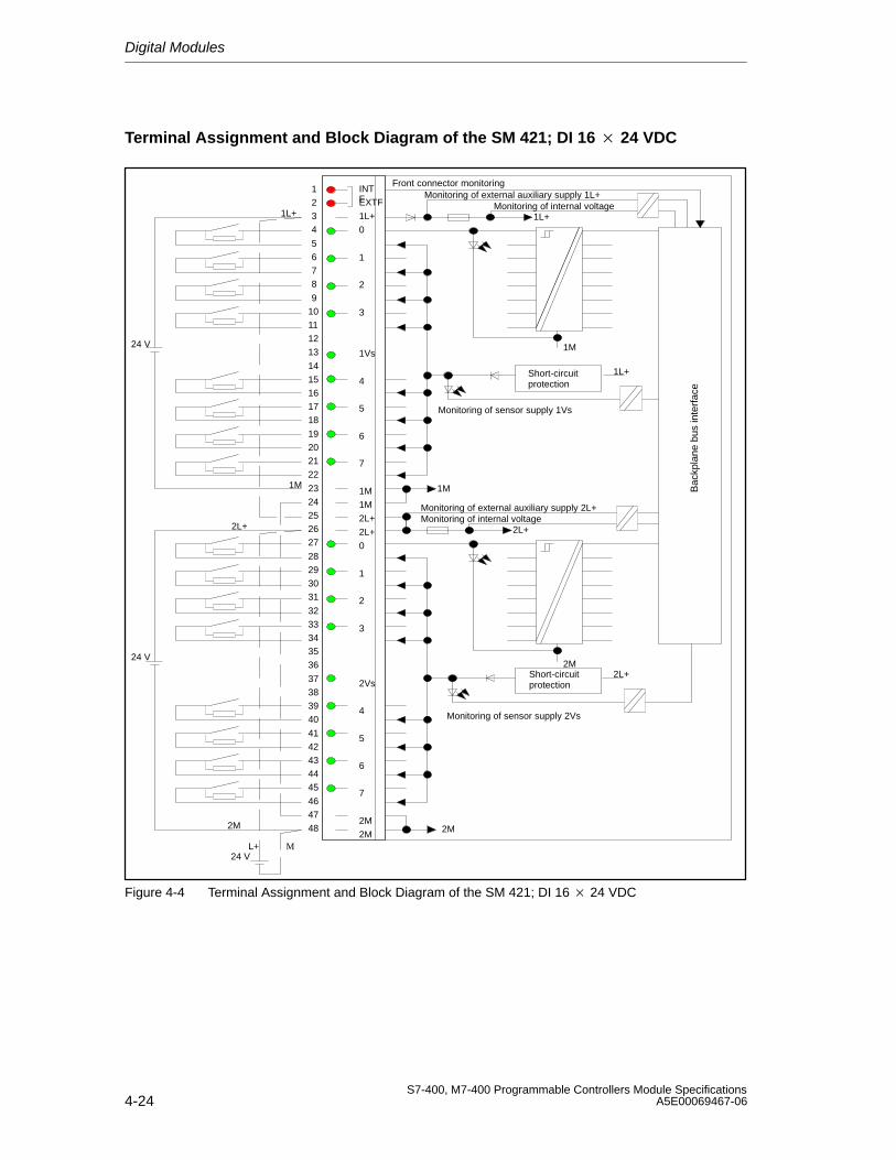
Digital Modules
4-24S7-400, M7-400 Programmable Controllers Module Specifications
A5E00069467-06
Terminal Assignment and Block Diagram of the SM 421; DI 16 24 VDC
INTFEXTF
1L+
0
1
2
3
1Vs
4
5
6
7
1M
1M
2L+
2L+
0
1
2
3
2Vs
4
5
6
7
2M
2M
1L+
2M
2L+
1M
ML+
1L+
1L+
2L+
1M
2M
2M
1M Bac
kpla
ne b
us in
terf
ace
24 V
24 V
24 V
Front connector monitoringMonitoring of external auxiliary supply 1L+
Monitoring of internal voltage
Monitoring of sensor supply 1Vs
2L+
Monitoring of external auxiliary supply 2L+Monitoring of internal voltage
Monitoring of sensor supply 2Vs
1234
5678
910111213
1415161718
19202122
2324252627
28293031
3233343536
37383940
4142434445
464748
Short-circuitprotection
Short-circuitprotection
Figure 4-4 Terminal Assignment and Block Diagram of the SM 421; DI 16 24 VDC
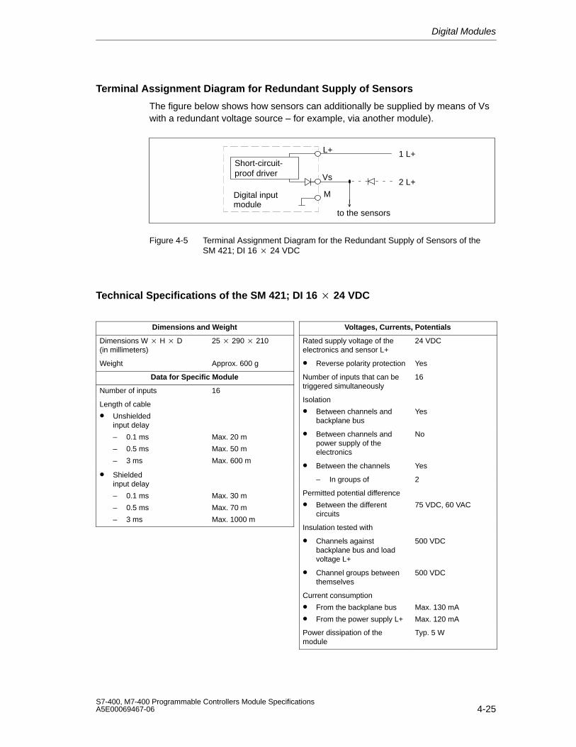
Digital Modules
4-25S7-400, M7-400 Programmable Controllers Module SpecificationsA5E00069467-06
Terminal Assignment Diagram for Redundant Supply of Sensors
The figure below shows how sensors can additionally be supplied by means of Vswith a redundant voltage source – for example, via another module).
Vs
M
L+ 1 L+
2 L+
to the sensors
Digital inputmodule
Short-circuit-proof driver
Figure 4-5 Terminal Assignment Diagram for the Redundant Supply of Sensors of the SM 421; DI 16 24 VDC
Technical Specifications of the SM 421; DI 16 24 VDC
Dimensions and Weight
Dimensions W H D(in millimeters)
25 290 210
Weight Approx. 600 g
Data for Specific Module
Number of inputs 16
Length of cable
• Unshieldedinput delay
– 0.1 ms
– 0.5 ms
– 3 ms
Max. 20 m
Max. 50 m
Max. 600 m
• Shieldedinput delay
– 0.1 ms
– 0.5 ms
– 3 ms
Max. 30 m
Max. 70 m
Max. 1000 m
Voltages, Currents, Potentials
Rated supply voltage of theelectronics and sensor L+
24 VDC
• Reverse polarity protection Yes
Number of inputs that can betriggered simultaneously
16
Isolation
• Between channels andbackplane bus
Yes
• Between channels andpower supply of theelectronics
No
• Between the channels Yes
– In groups of 2
Permitted potential difference
• Between the differentcircuits
75 VDC, 60 VAC
Insulation tested with
• Channels againstbackplane bus and loadvoltage L+
500 VDC
• Channel groups betweenthemselves
500 VDC
Current consumption
• From the backplane bus
• From the power supply L+
Max. 130 mA
Max. 120 mA
Power dissipation of themodule
Typ. 5 W
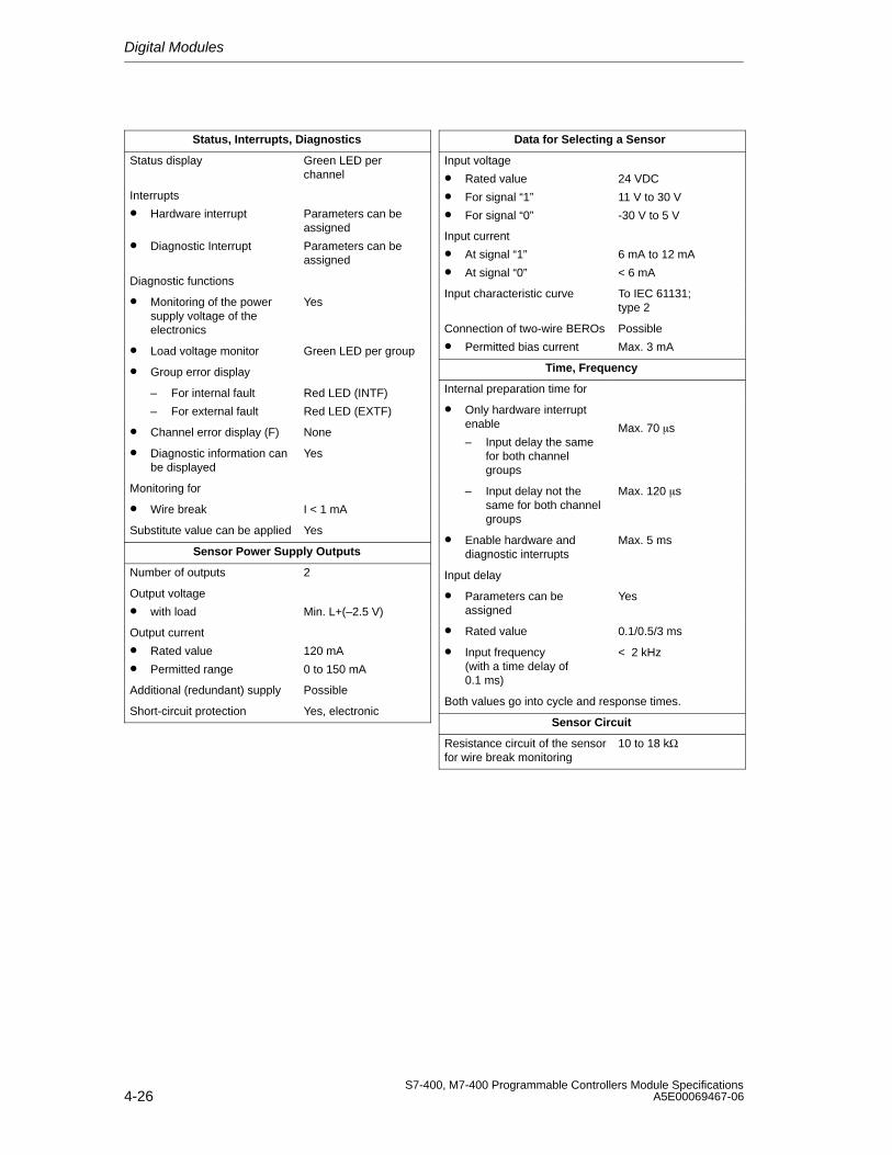
Digital Modules
4-26S7-400, M7-400 Programmable Controllers Module Specifications
A5E00069467-06
Status, Interrupts, Diagnostics
Status display Green LED perchannel
Interrupts
• Hardware interrupt
• Diagnostic Interrupt
Parameters can beassigned
Parameters can beassigned
Diagnostic functions
• Monitoring of the powersupply voltage of theelectronics
Yes
• Load voltage monitor Green LED per group
• Group error display
– For internal fault
– For external fault
Red LED (INTF)
Red LED (EXTF)
• Channel error display (F) None
• Diagnostic information canbe displayed
Yes
Monitoring for
• Wire break I < 1 mA
Substitute value can be applied Yes
Sensor Power Supply Outputs
Number of outputs 2
Output voltage
• with load Min. L+(–2.5 V)
Output current
• Rated value
• Permitted range
120 mA
0 to 150 mA
Additional (redundant) supply Possible
Short-circuit protection Yes, electronic
Data for Selecting a Sensor
Input voltage
• Rated value
• For signal “1”
• For signal “0”
24 VDC
11 V to 30 V
-30 V to 5 V
Input current
• At signal “1”
• At signal “0”
6 mA to 12 mA
< 6 mA
Input characteristic curve To IEC 61131; type 2
Connection of two-wire BEROs
• Permitted bias current
Possible
Max. 3 mA
Time, Frequency
Internal preparation time for
• Only hardware interruptenable
– Input delay the samefor both channelgroups
Max. 70 s
– Input delay not thesame for both channelgroups
Max. 120 s
• Enable hardware and diagnostic interrupts
Max. 5 ms
Input delay
• Parameters can beassigned
Yes
• Rated value 0.1/0.5/3 ms
• Input frequency (with a time delay of0.1 ms)
< 2 kHz
Both values go into cycle and response times.
Sensor Circuit
Resistance circuit of the sensorfor wire break monitoring
10 to 18 kΩ
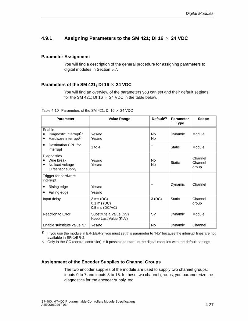
Digital Modules
4-27S7-400, M7-400 Programmable Controllers Module SpecificationsA5E00069467-06
4.9.1 Assigning Parameters to the SM 421; DI 16 24 VDC
Parameter Assignment
You will find a description of the general procedure for assigning parameters todigital modules in Section 5.7.
Parameters of the SM 421; DI 16 24 VDC
You will find an overview of the parameters you can set and their default settingsfor the SM 421; DI 16 24 VDC in the table below.
Table 4-10 Parameters of the SM 421; DI 16 24 VDC
Parameter Value Range Default2) ParameterType
Scope
Enable• Diagnostic interrupt1)
• Hardware interrupt1)Yes/noYes/no
NoNo
Dynamic Module
• Destination CPU forinterrupt
1 to 4–
Static Module
Diagnostics• Wire break• No load voltage
L+/sensor supply
Yes/noYes/no
NoNo
StaticChannelChannelgroup
Trigger for hardwareinterrupt
• Rising edge
• Falling edge
Yes/no
Yes/no
– Dynamic Channel
Input delay 3 ms (DC)0.1 ms (DC)0.5 ms (DC/AC)
3 (DC) Static Channelgroup
Reaction to Error Substitute a Value (SV)Keep Last Value (KLV)
SV Dynamic Module
Enable substitute value “1” Yes/no No Dynamic Channel
1) If you use the module in ER-1/ER-2, you must set this parameter to “No” because the interrupt lines are notavailable in ER-1/ER-2.
2) Only in the CC (central controller) is it possible to start up the digital modules with the default settings.
Assignment of the Encoder Supplies to Channel Groups
The two encoder supplies of the module are used to supply two channel groups:inputs 0 to 7 and inputs 8 to 15. In these two channel groups, you parameterize thediagnostics for the encoder supply, too.
Digital Modules
4-28S7-400, M7-400 Programmable Controllers Module Specifications
A5E00069467-06
Ensuring a Wire Break Check Is Carried Out
To ensure that a wire break check is carried out, you require an external sensorcircuit using a resistor of 10 to 18 k The resistor should be connected parallel tothe contact and should be arranged as closely as possible to the sensor.
This additional resistor is not required in the following cases:
• If two-wire BEROs are used
• If you don’t parameterize the “Wire Break” diagnosis
Setting the Input Delay for Channel Groups
You can only set the input delay for each group of channels. In other words, thesetting for channel 0 applies to inputs 0 to 7 and the setting for channel 8 applies toinputs 8 to 15.
Note
The parameters that are entered for the remaining channels (1 to 7 and 9 to 15)must be equal to the value 0 or 8, otherwise those channels will be reported asbeing incorrectly parameterized.
Any hardware interrupts that have occurred in the meantime will be reported afteracknowledgement.
Optimum Signal Propagation Delay
You can achieve the fastest signal propagation delay with the following settings:
• Both channel groups are parameterized with an input delay of 0.1 ms
• All the diagnoses (load voltage error, wire break) are deactivated
• Diagnostic interrupt is not enabled
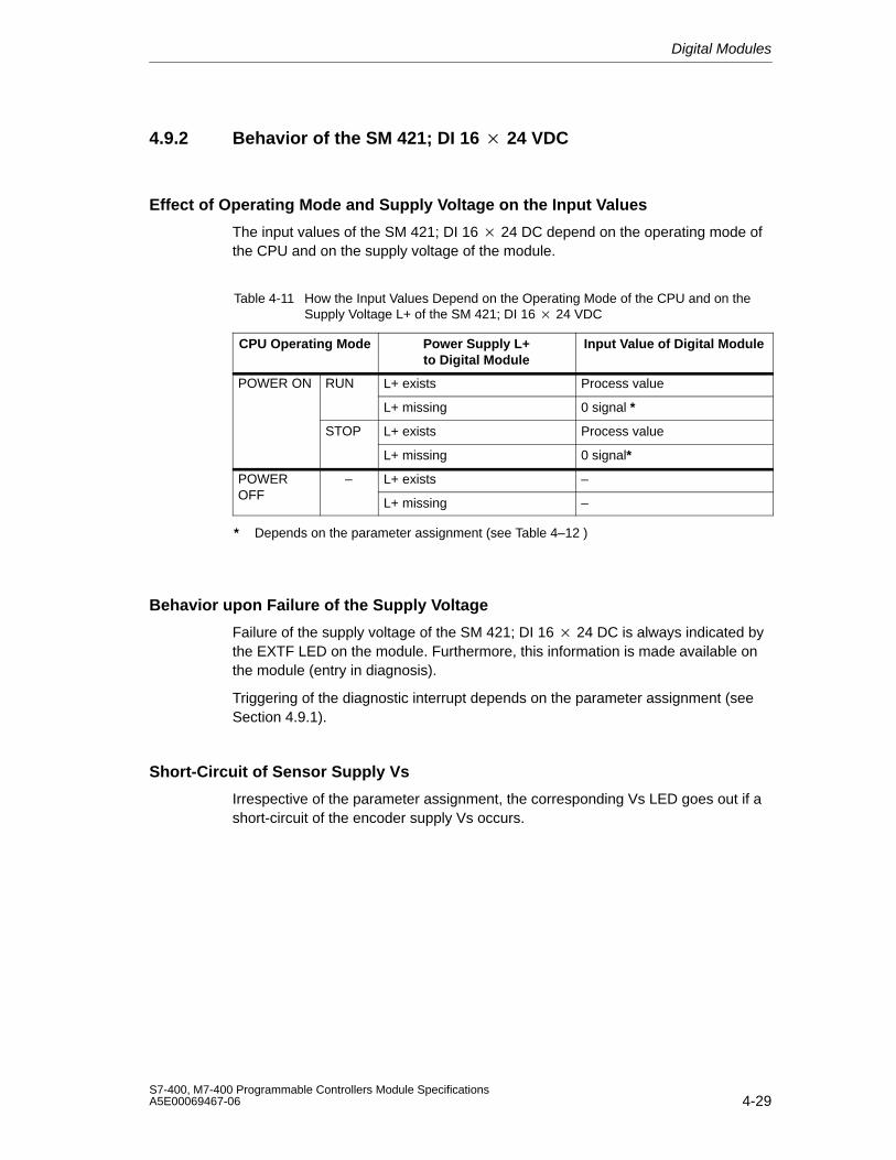
Digital Modules
4-29S7-400, M7-400 Programmable Controllers Module SpecificationsA5E00069467-06
4.9.2 Behavior of the SM 421; DI 16 24 VDC
Effect of Operating Mode and Supply Voltage on the Input Values
The input values of the SM 421; DI 16 24 DC depend on the operating mode ofthe CPU and on the supply voltage of the module.
Table 4-11 How the Input Values Depend on the Operating Mode of the CPU and on theSupply Voltage L+ of the SM 421; DI 16 24 VDC
CPU Operating Mode Power Supply L+to Digital Module
Input Value of Digital Module
POWER ON RUN L+ exists Process value
L+ missing 0 signal *
STOP L+ exists Process value
L+ missing 0 signal*
POWER – L+ exists –OFF
L+ missing –
* Depends on the parameter assignment (see Table 4–12 )
Behavior upon Failure of the Supply Voltage
Failure of the supply voltage of the SM 421; DI 16 24 DC is always indicated bythe EXTF LED on the module. Furthermore, this information is made available onthe module (entry in diagnosis).
Triggering of the diagnostic interrupt depends on the parameter assignment (seeSection 4.9.1).
Short-Circuit of Sensor Supply Vs
Irrespective of the parameter assignment, the corresponding Vs LED goes out if ashort-circuit of the encoder supply Vs occurs.
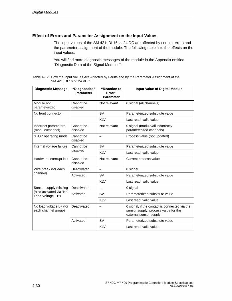
Digital Modules
4-30S7-400, M7-400 Programmable Controllers Module Specifications
A5E00069467-06
Effect of Errors and Parameter Assignment on the Input Values
The input values of the SM 421; DI 16 24 DC are affected by certain errors andthe parameter assignment of the module. The following table lists the effects on theinput values.
You will find more diagnostic messages of the module in the Appendix entitled“Diagnostic Data of the Signal Modules”.
Table 4-12 How the Input Values Are Affected by Faults and by the Parameter Assignment of the SM 421; DI 16 24 VDC
Diagnostic Message “Diagnostics”Parameter
“Reaction toError”
Parameter
Input Value of Digital Module
Module notparameterized
Cannot bedisabled
Not relevant 0 signal (all channels)
No front connector SV Parameterized substitute value
KLV Last read, valid value
Incorrect parameters(module/channel)
Cannot bedisabled
Not relevant 0 signal (module/all incorrectlyparameterized channels)
STOP operating mode Cannot bedisabled
– Process value (not updated)
Internal voltage failure Cannot be SV Parameterized substitute valuedisabled
KLV Last read, valid value
Hardware interrupt lost Cannot bedisabled
Not relevant Current process value
Wire break (for each Deactivated – 0 signalchannel)
Activated SV Parameterized substitute value
KLV Last read, valid value
Sensor supply missing Deactivated – 0 signal(also activated via ”NoLoad Voltage L+”)
Activated SV Parameterized substitute valueLoad Voltage L+”)KLV Last read, valid value
No load voltage L+ (foreach channel group)
Deactivated – 0 signal, if the contact is connected via thesensor supply; process value for theexternal sensor supply
Activated SV Parameterized substitute value
KLV Last read, valid value
Digital Modules
4-31S7-400, M7-400 Programmable Controllers Module SpecificationsA5E00069467-06
Behavior when the Input Delay Equals 0.1 ms and an Error Occurs
If you have parameterized the following:
• An input delay of 0.1 ms
• KLV or SV as the response to an error
• Substitute “1”
In the event of a fault on a channel that has a 1 signal, the following could occurbefore the last valid value or the substitute value ”1” is output:
• An 0 signal may be briefly output
• If parameterized, a hardware interrupt may be generated
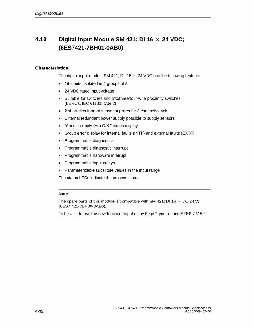
Digital Modules
4-32S7-400, M7-400 Programmable Controllers Module Specifications
A5E00069467-06
4.10 Digital Input Module SM 421; DI 16 24 VDC;(6ES7421-7BH01-0AB0)
Characteristics
The digital input module SM 421; DI 16 24 VDC has the following features:
• 16 inputs, isolated in 2 groups of 8
• 24 VDC rated input voltage
• Suitable for switches and two/three/four-wire proximity switches (BEROs, IEC 61131; type 2)
• 2 short-circuit-proof sensor supplies for 8 channels each
• External redundant power supply possible to supply sensors
• “Sensor supply (Vs) O.K.” status display
• Group error display for internal faults (INTF) and external faults (EXTF)
• Programmable diagnostics
• Programmable diagnostic interrupt
• Programmable hardware interrupt
• Programmable input delays
• Parameterizable substitute values in the input range
The status LEDs indicate the process status.
Note
The spare parts of this module is compatible with SM 421; DI 16 DC 24 V;(6ES7 421-7BH00-0AB0).
To be able to use the new function “input delay 50 s”, you require STEP 7 V 5.2.
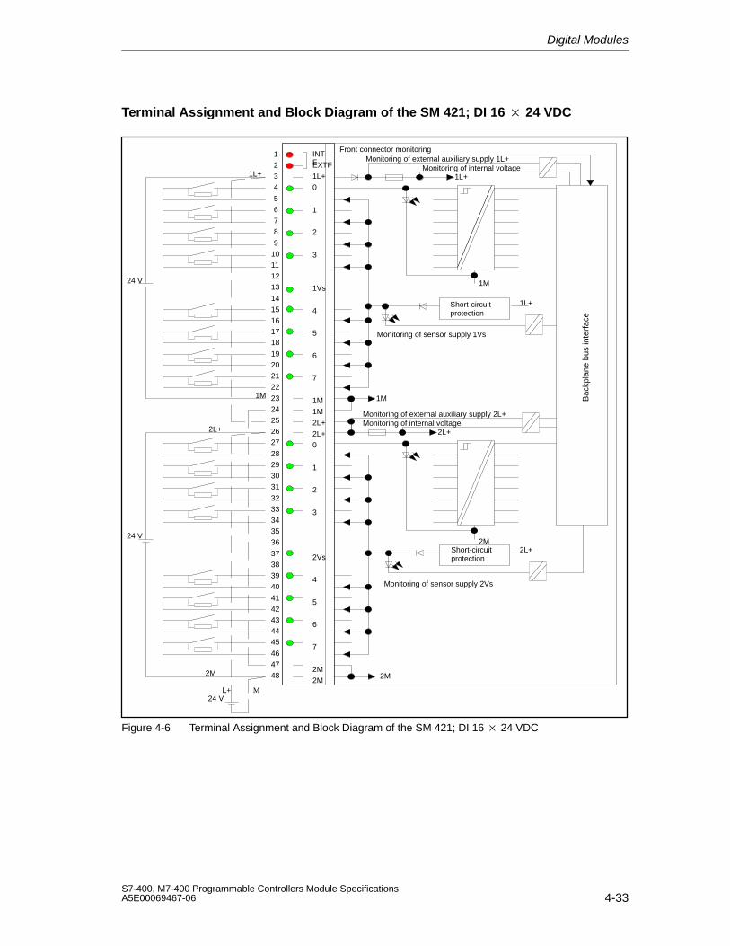
Digital Modules
4-33S7-400, M7-400 Programmable Controllers Module SpecificationsA5E00069467-06
Terminal Assignment and Block Diagram of the SM 421; DI 16 24 VDC
INTFEXTF
1L+
0
1
2
3
1Vs
4
5
6
7
1M
1M
2L+
2L+
0
1
2
3
2Vs
4
5
6
7
2M
2M
1L+
2M
2L+
1M
ML+
1L+
1L+
2L+
1M
2M
2M
1M Bac
kpla
ne b
us in
terf
ace
24 V
24 V
24 V
Front connector monitoringMonitoring of external auxiliary supply 1L+
Monitoring of internal voltage
Monitoring of sensor supply 1Vs
2L+
Monitoring of external auxiliary supply 2L+Monitoring of internal voltage
Monitoring of sensor supply 2Vs
1234
5678
910111213
1415161718
19202122
2324252627
28293031
3233343536
37383940
4142434445
464748
Short-circuitprotection
Short-circuitprotection
Figure 4-6 Terminal Assignment and Block Diagram of the SM 421; DI 16 24 VDC
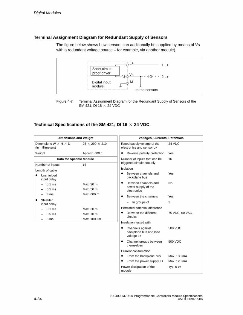
Digital Modules
4-34S7-400, M7-400 Programmable Controllers Module Specifications
A5E00069467-06
Terminal Assignment Diagram for Redundant Supply of Sensors
The figure below shows how sensors can additionally be supplied by means of Vswith a redundant voltage source – for example, via another module).
Vs
M
L+ 1 L+
2 L+
to the sensors
Digital inputmodule
Short-circuit-proof driver
Figure 4-7 Terminal Assignment Diagram for the Redundant Supply of Sensors of the SM 421; DI 16 24 VDC
Technical Specifications of the SM 421; DI 16 24 VDC
Dimensions and Weight
Dimensions W H D(in millimeters)
25 290 210
Weight Approx. 600 g
Data for Specific Module
Number of inputs 16
Length of cable
• Unshieldedinput delay
– 0.1 ms
– 0.5 ms
– 3 ms
Max. 20 m
Max. 50 m
Max. 600 m
• Shieldedinput delay
– 0.1 ms
– 0.5 ms
– 3 ms
Max. 30 m
Max. 70 m
Max. 1000 m
Voltages, Currents, Potentials
Rated supply voltage of theelectronics and sensor L+
24 VDC
• Reverse polarity protection Yes
Number of inputs that can betriggered simultaneously
16
Isolation
• Between channels andbackplane bus
Yes
• Between channels andpower supply of theelectronics
No
• Between the channels Yes
– In groups of 2
Permitted potential difference
• Between the differentcircuits
75 VDC, 60 VAC
Insulation tested with
• Channels againstbackplane bus and loadvoltage L+
500 VDC
• Channel groups betweenthemselves
500 VDC
Current consumption
• From the backplane bus
• From the power supply L+
Max. 130 mA
Max. 120 mA
Power dissipation of themodule
Typ. 5 W
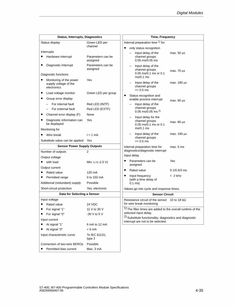
Digital Modules
4-35S7-400, M7-400 Programmable Controllers Module SpecificationsA5E00069467-06
Status, Interrupts, Diagnostics
Status display Green LED perchannel
Interrupts
• Hardware interrupt
• Diagnostic Interrupt
Parameters can beassigned
Parameters can beassigned
Diagnostic functions
• Monitoring of the powersupply voltage of theelectronics
Yes
• Load voltage monitor Green LED per group
• Group error display
– For internal fault
– For external fault
Red LED (INTF)
Red LED (EXTF)
• Channel error display (F) None
• Diagnostic information canbe displayed
Yes
Monitoring for
• Wire break I < 1 mA
Substitute value can be applied Yes
Sensor Power Supply Outputs
Number of outputs 2
Output voltage
• with load Min. L+(–2.5 V)
Output current
• Rated value
• Permitted range
120 mA
0 to 150 mA
Additional (redundant) supply Possible
Short-circuit protection Yes, electronic
Data for Selecting a Sensor
Input voltage
• Rated value
• For signal “1”
• For signal “0”
24 VDC
11 V to 30 V
-30 V to 5 V
Input current
• At signal “1”
• At signal “0”
6 mA to 12 mA
< 6 mA
Input characteristic curve To IEC 61131; type 2
Connection of two-wire BEROs
• Permitted bias current
Possible
Max. 3 mA
Time, Frequency
Internal preparation time 1) for
• only status recognition
– Input delay of thechannel groups 0.05 ms/0.05 ms
max. 50 s
– Input delay of thechannel groups 0.05 ms/0.1 ms or 0.1ms/0.1 ms
max. 70 s
– Input delay of thechannel groups >= 0.5 ms
max. 180 s
• Status recognition andenable process interrupt
– Input delay of thechannel groups 0.05 ms/0.05 ms 2)
max. 60 s
– Input delay for thechannel groups 0.05 ms/0.1 ms or 0.1ms/0.1 ms
max. 80 s
– Input delay of thechannel groups >= 0.5 ms
max. 190 s
Internal preparation time fordiagnostics/diagnostic interrupt
Input delay
max. 5 ms
• Parameters can beassigned
Yes
• Rated value 0.1/0.5/3 ms
• Input frequency (with a time delay of0.1 ms)
< 2 kHz
Values go into cycle and response times.
Sensor Circuit
Resistance circuit of the sensorfor wire break monitoring
10 to 18 kΩ
1) The filter times are added to the overall runtime of theselected input delay.2) Substitute functionality; diagnostics and diagnosticinterrupt are not to be selected.
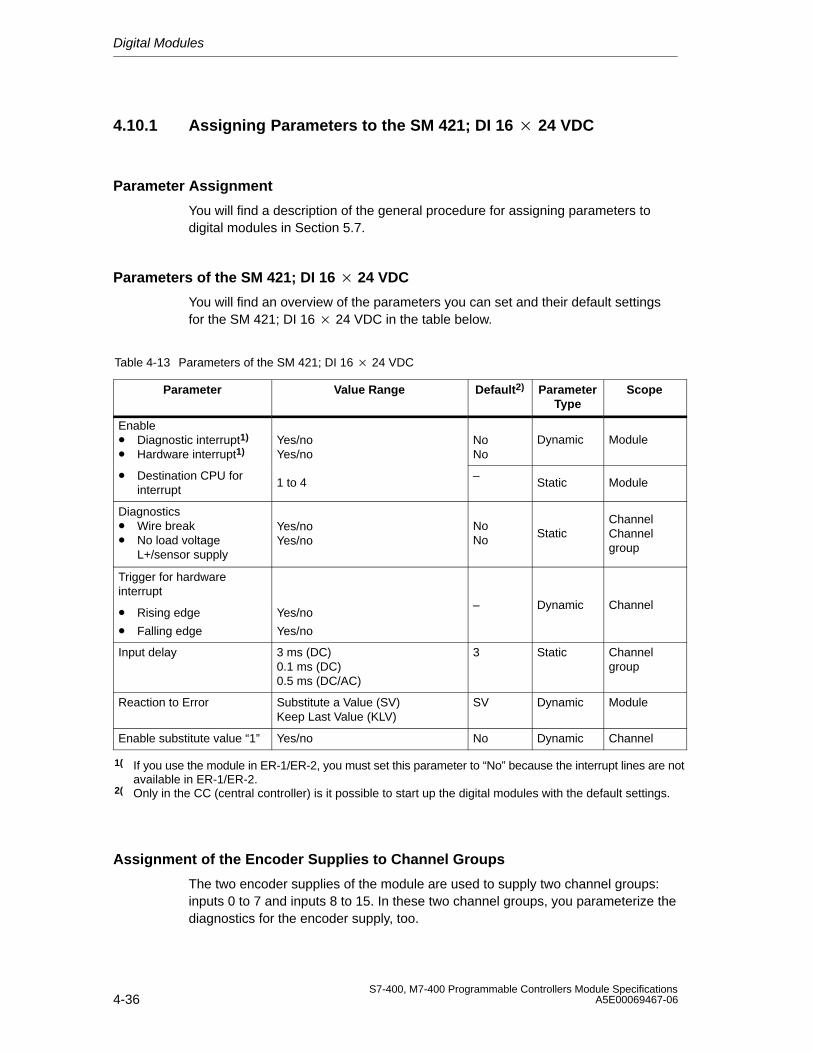
Digital Modules
4-36S7-400, M7-400 Programmable Controllers Module Specifications
A5E00069467-06
4.10.1 Assigning Parameters to the SM 421; DI 16 24 VDC
Parameter Assignment
You will find a description of the general procedure for assigning parameters todigital modules in Section 5.7.
Parameters of the SM 421; DI 16 24 VDC
You will find an overview of the parameters you can set and their default settingsfor the SM 421; DI 16 24 VDC in the table below.
Table 4-13 Parameters of the SM 421; DI 16 24 VDC
Parameter Value Range Default2) ParameterType
Scope
Enable• Diagnostic interrupt1)
• Hardware interrupt1)Yes/noYes/no
NoNo
Dynamic Module
• Destination CPU forinterrupt
1 to 4–
Static Module
Diagnostics• Wire break• No load voltage
L+/sensor supply
Yes/noYes/no
NoNo
StaticChannelChannelgroup
Trigger for hardwareinterrupt
• Rising edge
• Falling edge
Yes/no
Yes/no
– Dynamic Channel
Input delay 3 ms (DC)0.1 ms (DC)0.5 ms (DC/AC)
3 Static Channelgroup
Reaction to Error Substitute a Value (SV)Keep Last Value (KLV)
SV Dynamic Module
Enable substitute value “1” Yes/no No Dynamic Channel
1( If you use the module in ER-1/ER-2, you must set this parameter to “No” because the interrupt lines are notavailable in ER-1/ER-2.
2( Only in the CC (central controller) is it possible to start up the digital modules with the default settings.
Assignment of the Encoder Supplies to Channel Groups
The two encoder supplies of the module are used to supply two channel groups:inputs 0 to 7 and inputs 8 to 15. In these two channel groups, you parameterize thediagnostics for the encoder supply, too.
Digital Modules
4-37S7-400, M7-400 Programmable Controllers Module SpecificationsA5E00069467-06
Ensuring a Wire Break Check Is Carried Out
To ensure that a wire break check is carried out, you require an external sensorcircuit using a resistor of 10 to 18 k The resistor should be connected parallel tothe contact and should be arranged as closely as possible to the sensor.
This additional resistor is not required in the following cases:
• If two-wire BEROs are used
• If you don’t parameterize the “Wire Break” diagnosis
Setting the Input Delay for Channel Groups
You can only set the input delay for each group of channels. In other words, thesetting for channel 0 applies to inputs 0 to 7 and the setting for channel 8 applies toinputs 8 to 15.
Note
The parameters that are entered for the remaining channels (1 to 7 and 9 to 15)must be equal to the value 0 or 8, otherwise those channels will be reported asbeing incorrectly parameterized.
Any hardware interrupts that have occurred in the meantime will be reported afteracknowledgement.
Optimum Signal Propagation Delay
You can achieve the fastest signal propagation delay with the following settings:
• Both channel groups are parameterized with an input delay of 0.1 ms
• All the diagnoses (load voltage error, wire break) are deactivated
• Diagnostic interrupt is not enabled
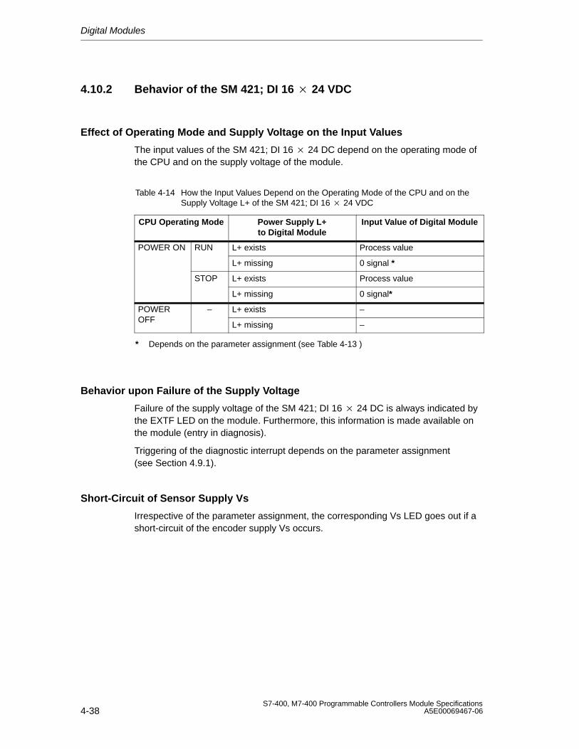
Digital Modules
4-38S7-400, M7-400 Programmable Controllers Module Specifications
A5E00069467-06
4.10.2 Behavior of the SM 421; DI 16 24 VDC
Effect of Operating Mode and Supply Voltage on the Input Values
The input values of the SM 421; DI 16 24 DC depend on the operating mode ofthe CPU and on the supply voltage of the module.
Table 4-14 How the Input Values Depend on the Operating Mode of the CPU and on theSupply Voltage L+ of the SM 421; DI 16 24 VDC
CPU Operating Mode Power Supply L+to Digital Module
Input Value of Digital Module
POWER ON RUN L+ exists Process value
L+ missing 0 signal *
STOP L+ exists Process value
L+ missing 0 signal*
POWER – L+ exists –OFF
L+ missing –
* Depends on the parameter assignment (see Table 4-13 )
Behavior upon Failure of the Supply Voltage
Failure of the supply voltage of the SM 421; DI 16 24 DC is always indicated bythe EXTF LED on the module. Furthermore, this information is made available onthe module (entry in diagnosis).
Triggering of the diagnostic interrupt depends on the parameter assignment (see Section 4.9.1).
Short-Circuit of Sensor Supply Vs
Irrespective of the parameter assignment, the corresponding Vs LED goes out if ashort-circuit of the encoder supply Vs occurs.
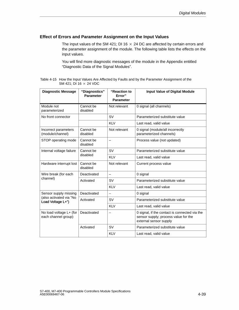
Digital Modules
4-39S7-400, M7-400 Programmable Controllers Module SpecificationsA5E00069467-06
Effect of Errors and Parameter Assignment on the Input Values
The input values of the SM 421; DI 16 24 DC are affected by certain errors andthe parameter assignment of the module. The following table lists the effects on theinput values.
You will find more diagnostic messages of the module in the Appendix entitled“Diagnostic Data of the Signal Modules”.
Table 4-15 How the Input Values Are Affected by Faults and by the Parameter Assignment of the SM 421; DI 16 24 VDC
Diagnostic Message “Diagnostics”Parameter
“Reaction toError”
Parameter
Input Value of Digital Module
Module notparameterized
Cannot bedisabled
Not relevant 0 signal (all channels)
No front connector SV Parameterized substitute value
KLV Last read, valid value
Incorrect parameters(module/channel)
Cannot bedisabled
Not relevant 0 signal (module/all incorrectlyparameterized channels)
STOP operating mode Cannot bedisabled
– Process value (not updated)
Internal voltage failure Cannot be SV Parameterized substitute valuedisabled
KLV Last read, valid value
Hardware interrupt lost Cannot bedisabled
Not relevant Current process value
Wire break (for each Deactivated – 0 signalchannel)
Activated SV Parameterized substitute value
KLV Last read, valid value
Sensor supply missing Deactivated – 0 signal(also activated via ”NoLoad Voltage L+”)
Activated SV Parameterized substitute valueLoad Voltage L+”)KLV Last read, valid value
No load voltage L+ (foreach channel group)
Deactivated – 0 signal, if the contact is connected via thesensor supply; process value for theexternal sensor supply
Activated SV Parameterized substitute value
KLV Last read, valid value
Digital Modules
4-40S7-400, M7-400 Programmable Controllers Module Specifications
A5E00069467-06
Behavior when the Input Delay Equals 0.1 ms and an Error Occurs
If you have parameterized the following:
• An input delay of 0.1 ms or 0.05 ms
• KLV or SV as the response to an error
• Substitute “1”
In the event of a fault on a channel that has a 1 signal, the following could occurbefore the last valid value or the substitute value ”1” is output:
• An 0 signal may be briefly output
• If parameterized, a hardware interrupt may be generated
Digital Modules
4-41S7-400, M7-400 Programmable Controllers Module SpecificationsA5E00069467-06
4.11 Digital Input Module SM 421; DI 16 120 VAC;
(6ES7421-5EH00-0AA0)
Characteristics
The SM 421; DI 16 120 VAC has the following features:
• 16 inputs, isolated
• 120 VAC rated input voltage
• Suitable for switches and two-wire proximity switches (BEROs, IEC 61131; type 2)

Digital Modules
4-42S7-400, M7-400 Programmable Controllers Module Specifications
A5E00069467-06
Terminal Assignment Diagram of the SM 421; DI 16 120 VAC
1234 0
Byte 0
56 178 29
10 311
13
1N
12
1415 41617 51819 62021 722
2423
262728293031323334
3635
383940414243444546
4847
25
37
0
1
2
3
4
5
6
7
2N
3N
4N
5N
6N
7N
8N
9N
10N
11N
12N
13N
14N
15N
16N
Byte 1
Adaptation
Process Module
Dat
a re
gis
ter
and
bu
s co
ntr
ol
Adaptation
Adaptation
Adaptation
Adaptation
Adaptation
Adaptation
Adaptation
Adaptation
Adaptation
Adaptation
Adaptation
Adaptation
Adaptation
Adaptation
Adaptation
Figure 4-8 Terminal Assignment Diagram of the SM 421; DI 16 120 VDC
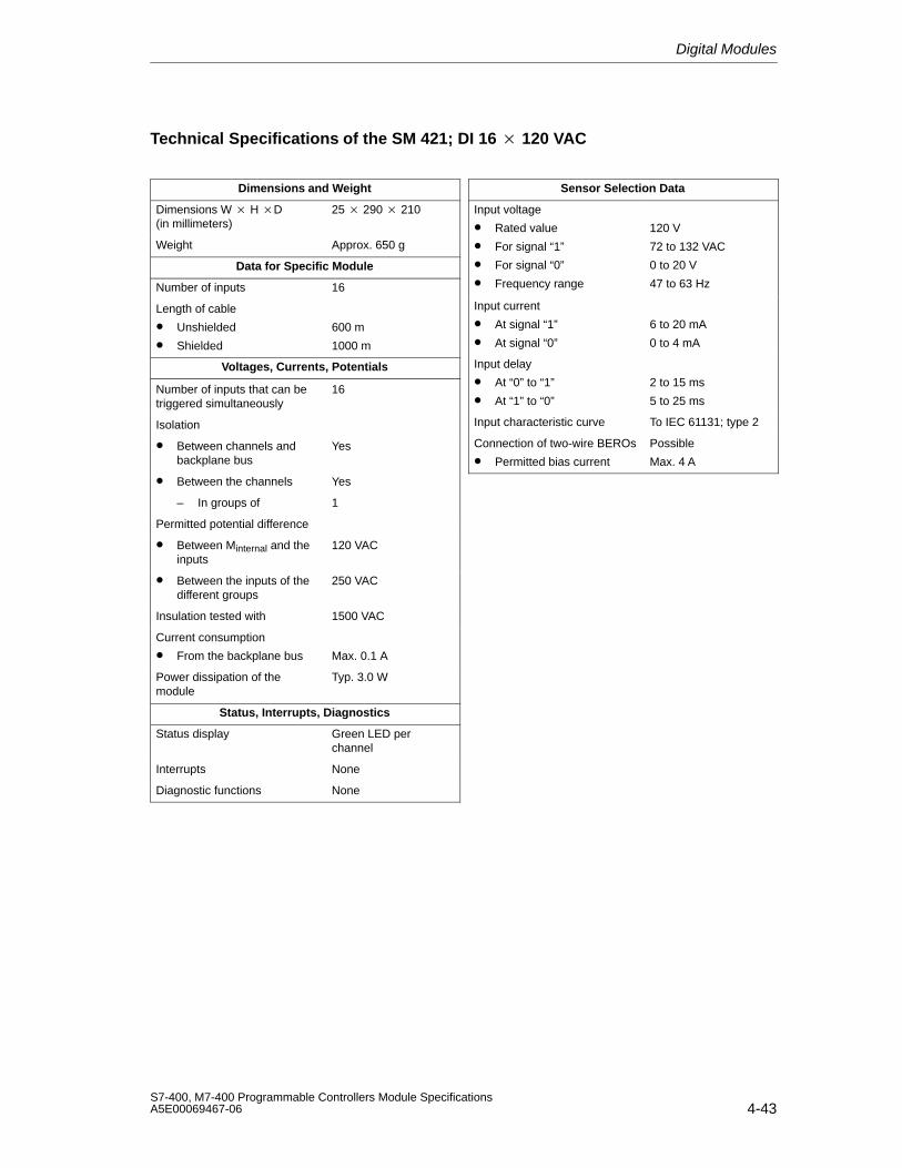
Digital Modules
4-43S7-400, M7-400 Programmable Controllers Module SpecificationsA5E00069467-06
Technical Specifications of the SM 421; DI 16 120 VAC
Dimensions and Weight
Dimensions W H D(in millimeters)
25 290 210
Weight Approx. 650 g
Data for Specific Module
Number of inputs 16
Length of cable
• Unshielded
• Shielded
600 m
1000 m
Voltages, Currents, Potentials
Number of inputs that can betriggered simultaneously
16
Isolation
• Between channels andbackplane bus
Yes
• Between the channels Yes
– In groups of 1
Permitted potential difference
• Between Minternal and theinputs
120 VAC
• Between the inputs of thedifferent groups
250 VAC
Insulation tested with 1500 VAC
Current consumption
• From the backplane bus Max. 0.1 A
Power dissipation of themodule
Typ. 3.0 W
Status, Interrupts, Diagnostics
Status display Green LED perchannel
Interrupts None
Diagnostic functions None
Sensor Selection Data
Input voltage
• Rated value
• For signal “1”
• For signal “0”
• Frequency range
120 V
72 to 132 VAC
0 to 20 V
47 to 63 Hz
Input current
• At signal “1”
• At signal “0”
6 to 20 mA
0 to 4 mA
Input delay
• At “0” to “1”
• At “1” to “0”
2 to 15 ms
5 to 25 ms
Input characteristic curve To IEC 61131; type 2
Connection of two-wire BEROs
• Permitted bias current
Possible
Max. 4 A
Digital Modules
4-44S7-400, M7-400 Programmable Controllers Module Specifications
A5E00069467-06
4.12 Digital Input Module SM 421; DI 16 24/60 VUC;(6ES7 421-7DH00-0AB0)
Characteristics
The SM 421; DI 16 24/60 VUC is characterized by the following features:
• 16 inputs, individually isolated
• Rated input voltage 24 VUC to 60 VUC
• Suitable for switches and two-wire proximity switches (BEROs)
• Suitable as active high and active low input
• Group error display for internal faults (INTF) and external faults (EXTF)
• Programmable diagnostics
• Programmable diagnostic interrupt
• Programmable hardware interrupt
• Programmable input delays
The status LEDs indicate the process status.
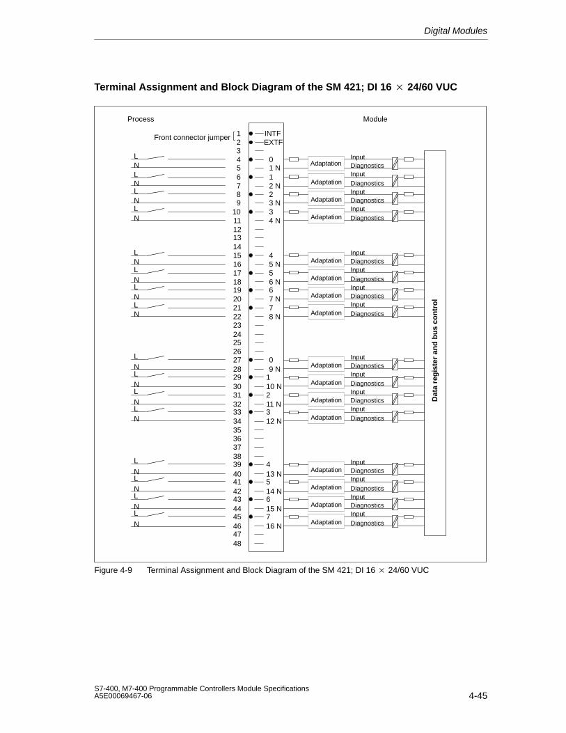
Digital Modules
4-45S7-400, M7-400 Programmable Controllers Module SpecificationsA5E00069467-06
Terminal Assignment and Block Diagram of the SM 421; DI 16 24/60 VUC
LN
123456789
101112131415161718192021222324252627282930313233343536373839404142434445464748
1 N1
2
4 N
4
5
6
0
2 N
3 N3
5 N
6 N
7 N78 N
09 N
110 N211 N312 N
413 N514 N615 N716 N
INTFEXTF
NLNLN
LNLNLNLN
LNLNLNLN
L
NLNLNL
N
L
InputDiagnostics
Adaptation
Adaptation
Adaptation
Adaptation
Adaptation
Adaptation
Adaptation
Adaptation
Adaptation
Adaptation
Adaptation
Adaptation
Adaptation
Adaptation
Adaptation
InputDiagnostics
DiagnosticsInput
DiagnosticsInput
InputDiagnosticsInputDiagnostics
DiagnosticsInput
DiagnosticsInput
InputDiagnosticsInputDiagnostics
DiagnosticsInput
DiagnosticsInput
InputDiagnosticsInputDiagnostics
DiagnosticsInput
DiagnosticsInput
Dat
a re
gis
ter
and
bu
s co
ntr
ol
Adaptation
Process
Front connector jumper
Module
Figure 4-9 Terminal Assignment and Block Diagram of the SM 421; DI 16 24/60 VUC
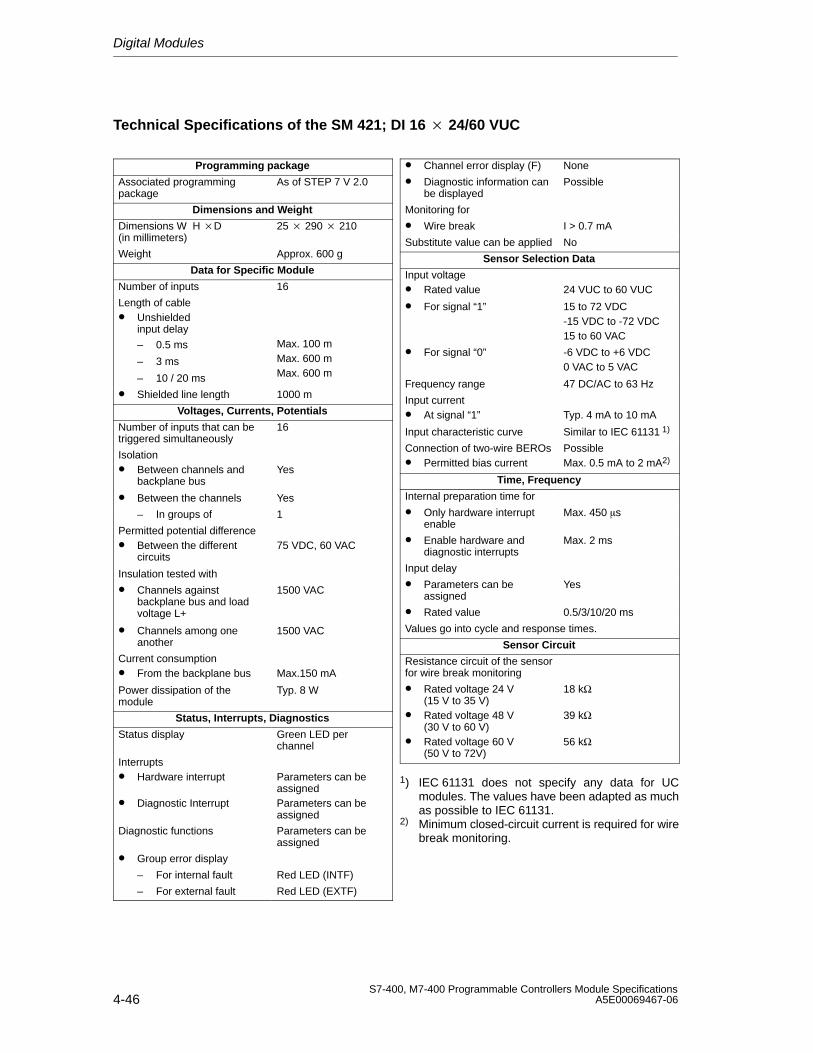
Digital Modules
4-46S7-400, M7-400 Programmable Controllers Module Specifications
A5E00069467-06
Technical Specifications of the SM 421; DI 16 24/60 VUC
Programming package
Associated programmingpackage
As of STEP 7 V 2.0
Dimensions and Weight
Dimensions W H D(in millimeters)
25 290 210
Weight Approx. 600 g
Data for Specific Module
Number of inputs 16
Length of cable• Unshielded
input delay
– 0.5 ms
– 3 ms
– 10 / 20 ms
Max. 100 mMax. 600 mMax. 600 m
• Shielded line length 1000 m
Voltages, Currents, Potentials
Number of inputs that can betriggered simultaneously
16
Isolation• Between channels and
backplane busYes
• Between the channels Yes
– In groups of 1
Permitted potential difference• Between the different
circuits75 VDC, 60 VAC
Insulation tested with
• Channels againstbackplane bus and loadvoltage L+
1500 VAC
• Channels among oneanother
1500 VAC
Current consumption• From the backplane bus Max.150 mA
Power dissipation of themodule
Typ. 8 W
Status, Interrupts, Diagnostics
Status display Green LED perchannel
Interrupts• Hardware interrupt
• Diagnostic Interrupt
Parameters can beassignedParameters can beassigned
Diagnostic functions Parameters can beassigned
• Group error display
– For internal fault Red LED (INTF)
– For external fault Red LED (EXTF)
• Channel error display (F) None
• Diagnostic information canbe displayed
Possible
Monitoring for
• Wire break I > 0.7 mA
Substitute value can be applied No
Sensor Selection Data
Input voltage• Rated value 24 VUC to 60 VUC
• For signal “1” 15 to 72 VDC-15 VDC to -72 VDC15 to 60 VAC
• For signal “0” -6 VDC to +6 VDC0 VAC to 5 VAC
Frequency range 47 DC/AC to 63 Hz
Input current• At signal “1” Typ. 4 mA to 10 mA
Input characteristic curve Similar to IEC 61131 1)
Connection of two-wire BEROs• Permitted bias current
PossibleMax. 0.5 mA to 2 mA2)
Time, Frequency
Internal preparation time for
• Only hardware interruptenable
Max. 450 s
• Enable hardware and diagnostic interrupts
Max. 2 ms
Input delay
• Parameters can beassigned
Yes
• Rated value 0.5/3/10/20 ms
Values go into cycle and response times.
Sensor Circuit
Resistance circuit of the sensorfor wire break monitoring
• Rated voltage 24 V(15 V to 35 V)
• Rated voltage 48 V(30 V to 60 V)
• Rated voltage 60 V(50 V to 72V)
18 kΩ
39 kΩ
56 kΩ
1) IEC 61131 does not specify any data for UCmodules. The values have been adapted as muchas possible to IEC 61131.
2) Minimum closed-circuit current is required for wirebreak monitoring.
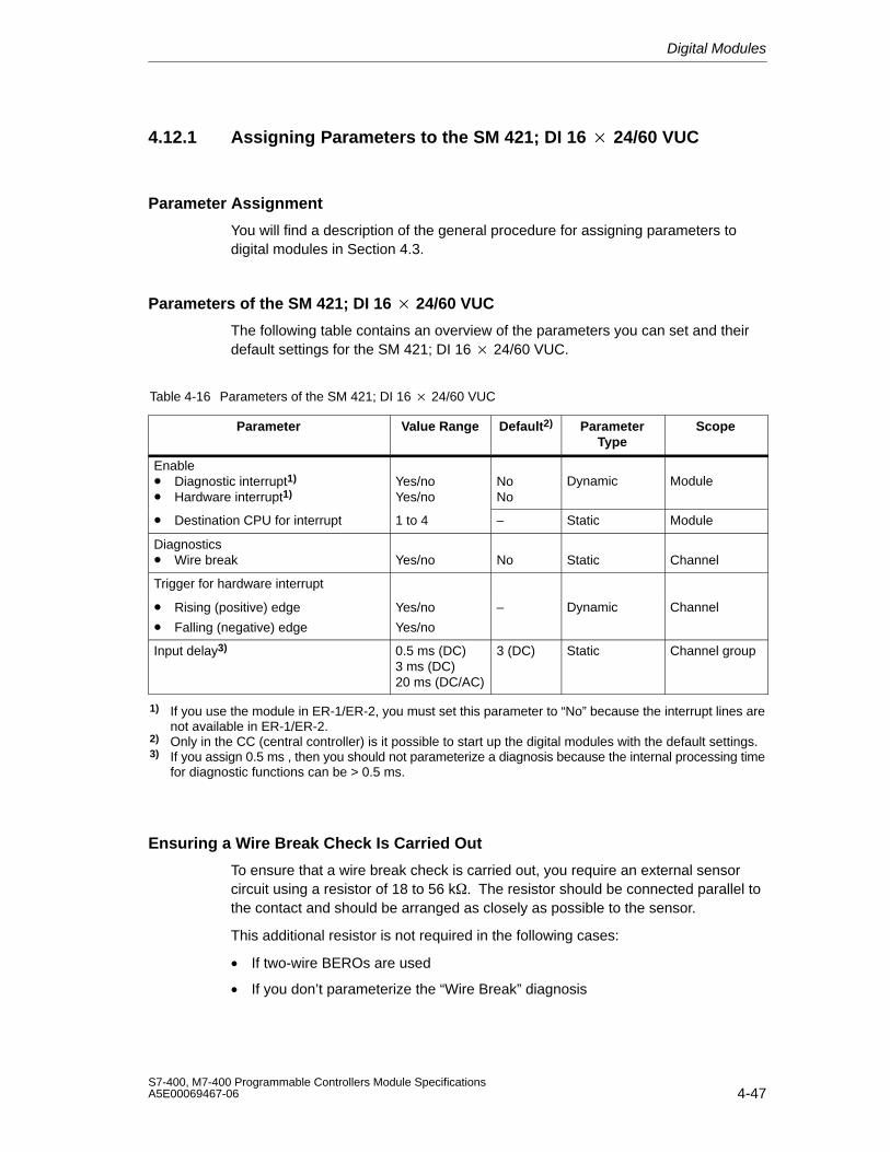
Digital Modules
4-47S7-400, M7-400 Programmable Controllers Module SpecificationsA5E00069467-06
4.12.1 Assigning Parameters to the SM 421; DI 16 24/60 VUC
Parameter Assignment
You will find a description of the general procedure for assigning parameters todigital modules in Section 4.3.
Parameters of the SM 421; DI 16 24/60 VUC
The following table contains an overview of the parameters you can set and theirdefault settings for the SM 421; DI 16 24/60 VUC.
Table 4-16 Parameters of the SM 421; DI 16 24/60 VUC
Parameter Value Range Default2) ParameterType
Scope
Enable• Diagnostic interrupt1)
• Hardware interrupt1)Yes/noYes/no
NoNo
Dynamic Module
• Destination CPU for interrupt 1 to 4 – Static Module
Diagnostics• Wire break Yes/no No Static Channel
Trigger for hardware interrupt
• Rising (positive) edge
• Falling (negative) edge
Yes/no
Yes/no
– Dynamic Channel
Input delay3) 0.5 ms (DC)3 ms (DC)20 ms (DC/AC)
3 (DC) Static Channel group
1) If you use the module in ER-1/ER-2, you must set this parameter to “No” because the interrupt lines arenot available in ER-1/ER-2.
2) Only in the CC (central controller) is it possible to start up the digital modules with the default settings.3) If you assign 0.5 ms , then you should not parameterize a diagnosis because the internal processing time
for diagnostic functions can be > 0.5 ms.
Ensuring a Wire Break Check Is Carried Out
To ensure that a wire break check is carried out, you require an external sensorcircuit using a resistor of 18 to 56 k The resistor should be connected parallel tothe contact and should be arranged as closely as possible to the sensor.
This additional resistor is not required in the following cases:
• If two-wire BEROs are used
• If you don’t parameterize the “Wire Break” diagnosis
Digital Modules
4-48S7-400, M7-400 Programmable Controllers Module Specifications
A5E00069467-06
Setting the Input Delay for Channel Groups
You can only set the input delay for each group of channels. In other words, thesetting for channel 0 applies to inputs 0 to 7 and the setting for channel 8 applies toinputs 8 to 15.
Note
The parameters that are entered for the remaining channels (1 to 7 and 9 to 15)must be equal to the value 0 or 8, otherwise those channels will be reported asbeing incorrectly parameterized.
Any hardware interrupts that have occurred in the meantime will be reported afteracknowledgement.
Optimum Signal Propagation Delays
You can achieve the fastest signal propagation delay with the following settings:
• Both channel groups are parameterized with an input delay of 0.5 ms
• The Diagnostics parameter is disabled
• The Diagnostic Interrupt parameter is disabled
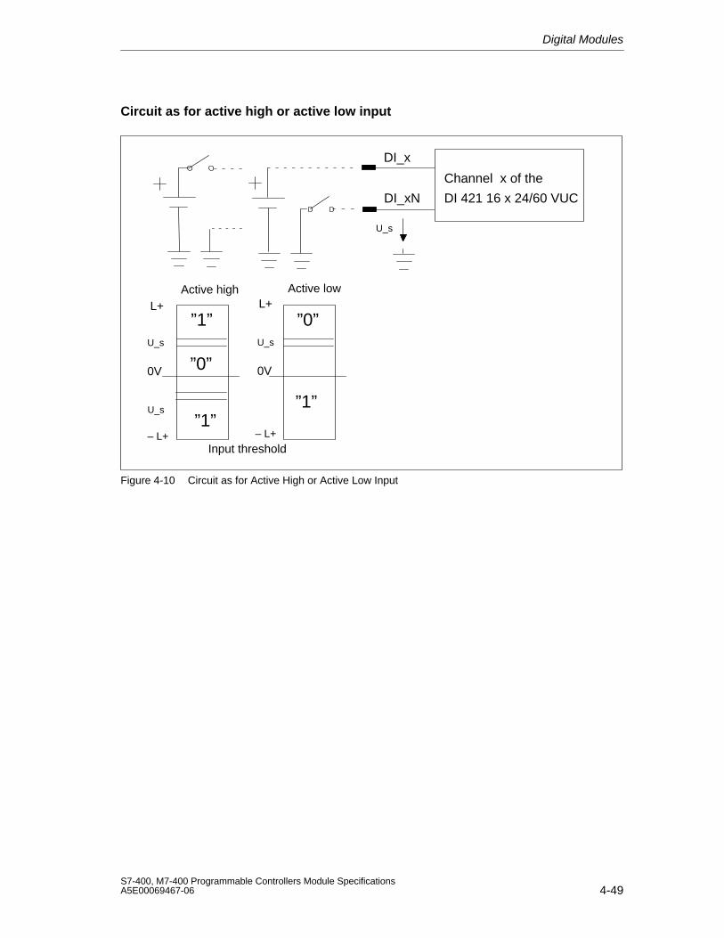
Digital Modules
4-49S7-400, M7-400 Programmable Controllers Module SpecificationsA5E00069467-06
Circuit as for active high or active low input
”1”
”0”0V
– L+
U_s
”1”U_s
DI_x
”1”
”0”
0V
L+
– L+
U_s
DI_xN
Channel x of the
DI 421 16 x 24/60 VUC
L+
U_s
Input threshold
Active high Active low
Figure 4-10 Circuit as for Active High or Active Low Input
Digital Modules
4-50S7-400, M7-400 Programmable Controllers Module Specifications
A5E00069467-06
4.13 Digital Input Module SM 421; DI 16 120/230 VUC;(6ES7 421-1FH00-0AA0)
Characteristics
The SM 421; DI 16 120/230 VUC is characterized by the following features:
• 16 inputs, isolated
• Rated input voltage 120/230 VAC/VDC
• Suitable for switches and two-wire proximity switches
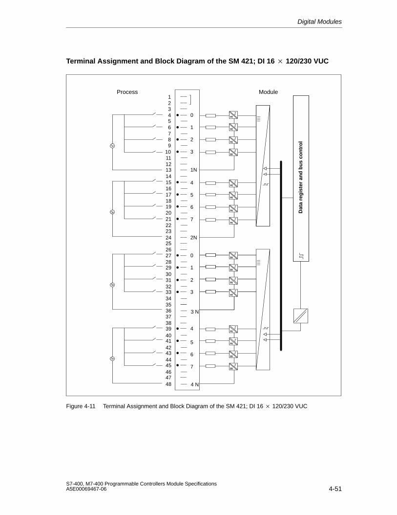
Digital Modules
4-51S7-400, M7-400 Programmable Controllers Module SpecificationsA5E00069467-06
Terminal Assignment and Block Diagram of the SM 421; DI 16 120/230 VUC
123456789
101112131415161718192021222324252627282930313233343536373839404142434445464748 4 N
3 N
1
2
0
3
5
6
4
7
5
6
4
7
1
2
0
3
1N
2N
Dat
a re
gis
ter
and
bu
s co
ntr
ol
Process Module
Figure 4-11 Terminal Assignment and Block Diagram of the SM 421; DI 16 120/230 VUC
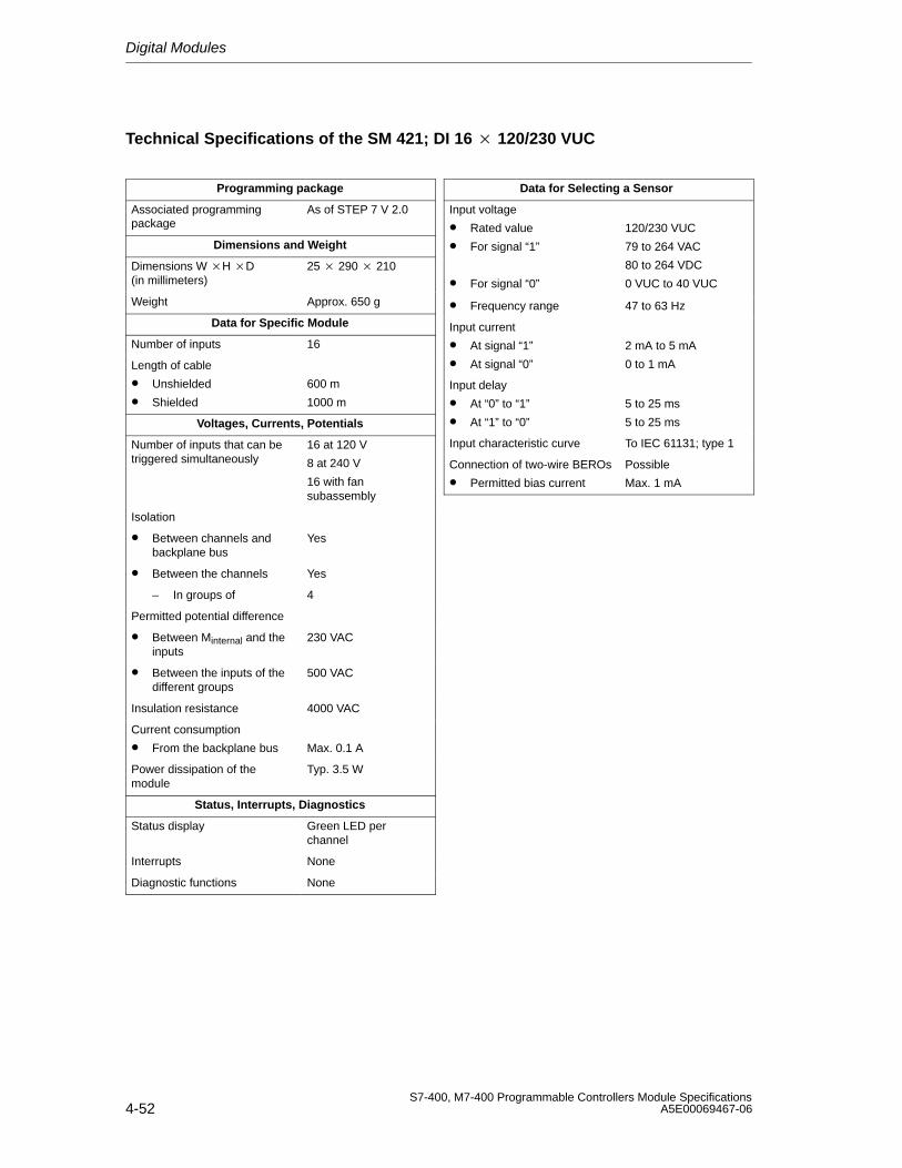
Digital Modules
4-52S7-400, M7-400 Programmable Controllers Module Specifications
A5E00069467-06
Technical Specifications of the SM 421; DI 16 120/230 VUC
Programming package
Associated programmingpackage
As of STEP 7 V 2.0
Dimensions and Weight
Dimensions W H D(in millimeters)
25 290 210
Weight Approx. 650 g
Data for Specific Module
Number of inputs 16
Length of cable
• Unshielded
• Shielded
600 m
1000 m
Voltages, Currents, Potentials
Number of inputs that can betriggered simultaneously
16 at 120 V
8 at 240 V
16 with fansubassembly
Isolation
• Between channels andbackplane bus
Yes
• Between the channels Yes
– In groups of 4
Permitted potential difference
• Between Minternal and theinputs
230 VAC
• Between the inputs of thedifferent groups
500 VAC
Insulation resistance 4000 VAC
Current consumption
• From the backplane bus Max. 0.1 A
Power dissipation of themodule
Typ. 3.5 W
Status, Interrupts, Diagnostics
Status display Green LED perchannel
Interrupts None
Diagnostic functions None
Data for Selecting a Sensor
Input voltage
• Rated value
• For signal “1”
• For signal “0”
120/230 VUC
79 to 264 VAC
80 to 264 VDC
0 VUC to 40 VUC
• Frequency range 47 to 63 Hz
Input current
• At signal “1”
• At signal “0”
2 mA to 5 mA
0 to 1 mA
Input delay
• At “0” to “1”
• At “1” to “0”
5 to 25 ms
5 to 25 ms
Input characteristic curve To IEC 61131; type 1
Connection of two-wire BEROs
• Permitted bias current
Possible
Max. 1 mA
Digital Modules
4-53S7-400, M7-400 Programmable Controllers Module SpecificationsA5E00069467-06
4.14 Digital Input Module SM 421; DI 16 120/230 VUC;(6ES7421-1FH20-0AA0)
Characteristics
The SM 421; DI 16 120/230 VUC is characterized by the following features:
• 16 inputs, isolated in groups of 4
• Rated input voltage 120/230 VUC
• Input characteristic curve to IEC 61131; type 2
• Suitable for switches and two-wire proximity switches (BEROs)
The status LEDs indicate the process status.
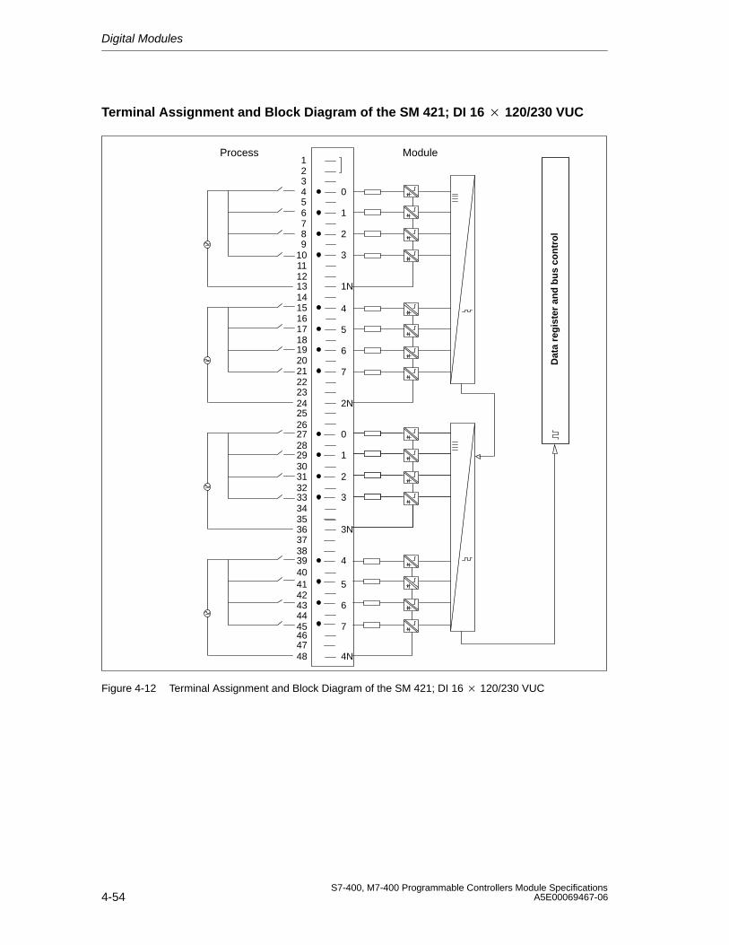
Digital Modules
4-54S7-400, M7-400 Programmable Controllers Module Specifications
A5E00069467-06
Terminal Assignment and Block Diagram of the SM 421; DI 16 120/230 VUC
123456789
1112131415161718192021222324252627282930313233343536373839404142434445464748
1
2
0
3
5
6
4
7
5
6
4
7
1
2
0
3
4N
1N
Dat
a re
gis
ter
and
bu
s co
ntr
ol
10
2N
3N
Process Module
Figure 4-12 Terminal Assignment and Block Diagram of the SM 421; DI 16 120/230 VUC
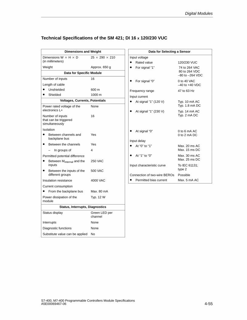
Digital Modules
4-55S7-400, M7-400 Programmable Controllers Module SpecificationsA5E00069467-06
Technical Specifications of the SM 421; DI 16 x 120/230 VUC
Dimensions and Weight
Dimensions W H D(in millimeters)
25 290 210
Weight Approx. 650 g
Data for Specific Module
Number of inputs 16
Length of cable
• Unshielded
• Shielded
600 m
1000 m
Voltages, Currents, Potentials
Power rated voltage of theelectronics L+
None
Number of inputsthat can be triggeredsimultaneously
16
Isolation
• Between channels andbackplane bus
Yes
• Between the channels Yes
– In groups of 4
Permitted potential difference
• Between Minternal and theinputs
250 VAC
• Between the inputs of thedifferent groups
500 VAC
Insulation resistance 4000 VAC
Current consumption
• From the backplane bus Max. 80 mA
Power dissipation of themodule
Typ. 12 W
Status, Interrupts, Diagnostics
Status display Green LED perchannel
Interrupts None
Diagnostic functions None
Substitute value can be applied No
Data for Selecting a Sensor
Input voltage
• Rated value
• For signal “1”
120/230 VUC
74 to 264 VAC 80 to 264 VDC–80 to –264 VDC
• For signal “0” 0 to 40 VAC–40 to +40 VDC
Frequency range 47 to 63 Hz
Input current
• At signal ”1” (120 V) Typ. 10 mA ACTyp. 1.8 mA DC
• At signal ”1” (230 V) Typ. 14 mA ACTyp. 2 mA DC
• At signal “0” 0 to 6 mA AC0 to 2 mA DC
Input delay
• At “0” to “1” Max. 20 ms ACMax. 15 ms DC
• At “1” to “0” Max. 30 ms ACMax. 25 ms DC
Input characteristic curve To IEC 61131; type 2
Connection of two-wire BEROs
• Permitted bias current
Possible
Max. 5 mA AC
Digital Modules
4-56S7-400, M7-400 Programmable Controllers Module Specifications
A5E00069467-06
4.15 Digital Input Module SM 421; DI 32 120 VUC;
(6ES7421-1EL00-0AA0)
Characteristics
The SM 421; DI 32 120 VUC is characterized by the following features:
• 32 inputs, isolated
• Rated input voltage 120 VAC/VDC
• Suitable for switches and two-wire proximity switches
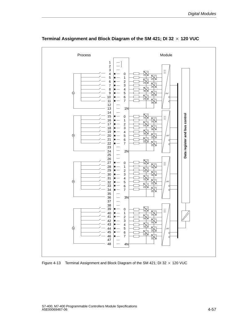
Digital Modules
4-57S7-400, M7-400 Programmable Controllers Module SpecificationsA5E00069467-06
Terminal Assignment and Block Diagram of the SM 421; DI 32 120 VUC
123456789
101112131415161718192021222324252627282930313233343536373839404142434445464748
1234567
0
4N
1234567
0
1234567
0
1234567
0
3N
2N
1N
Dat
a re
gis
ter
and
bu
s co
ntr
ol
Process Module
Figure 4-13 Terminal Assignment and Block Diagram of the SM 421; DI 32 120 VUC
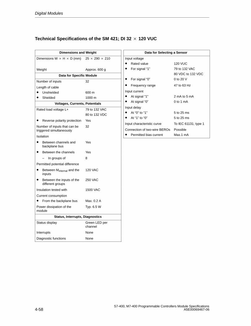
Digital Modules
4-58S7-400, M7-400 Programmable Controllers Module Specifications
A5E00069467-06
Technical Specifications of the SM 421; DI 32 120 VUC
Dimensions and Weight
Dimensions W H D (mm) 25 290 210
Weight Approx. 600 g
Data for Specific Module
Number of inputs 32
Length of cable
• Unshielded
• Shielded
600 m
1000 m
Voltages, Currents, Potentials
Rated load voltage L+ 79 to 132 VAC
80 to 132 VDC
• Reverse polarity protection Yes
Number of inputs that can betriggered simultaneously
32
Isolation
• Between channels andbackplane bus
Yes
• Between the channels Yes
– In groups of 8
Permitted potential difference
• Between Minternal and theinputs
120 VAC
• Between the inputs of thedifferent groups
250 VAC
Insulation tested with 1500 VAC
Current consumption
• From the backplane bus Max. 0.2 A
Power dissipation of themodule
Typ. 6.5 W
Status, Interrupts, Diagnostics
Status display Green LED perchannel
Interrupts None
Diagnostic functions None
Data for Selecting a Sensor
Input voltage
• Rated value
• For signal “1”
• For signal “0”
120 VUC
79 to 132 VAC
80 VDC to 132 VDC
0 to 20 V
• Frequency range 47 to 63 Hz
Input current
• At signal “1”
• At signal “0”
2 mA to 5 mA
0 to 1 mA
Input delay
• At “0” to “1”
• At “1” to “0”
5 to 25 ms
5 to 25 ms
Input characteristic curve To IEC 61131; type 1
Connection of two-wire BEROs
• Permitted bias current
Possible
Max.1 mA
Digital Modules
4-59S7-400, M7-400 Programmable Controllers Module SpecificationsA5E00069467-06
4.16 Digital Output Module SM 422;DO 16 24 VDC/2 A; (6ES7422-1BH10-0AA0)
Characteristics
The digital output module SM 422; DO 16 24 VDC/2 A has the followingfeatures.
• 16 outputs, isolated in two groups of 8
• 2 A output current
• 24 VDC rated load voltage
The status LEDs also indicate the system status even when the front connector isnot inserted.
!Caution
To commission the module, the rated load voltage must be applied at least once toeach group of 8 outputs (e.g. connection of 1L and 3L). If voltage is not applied toa group due, for example, to 1L and 2L failing, all the outputs switch off, eventhose in the second group. The status LED continues to function in the same way.
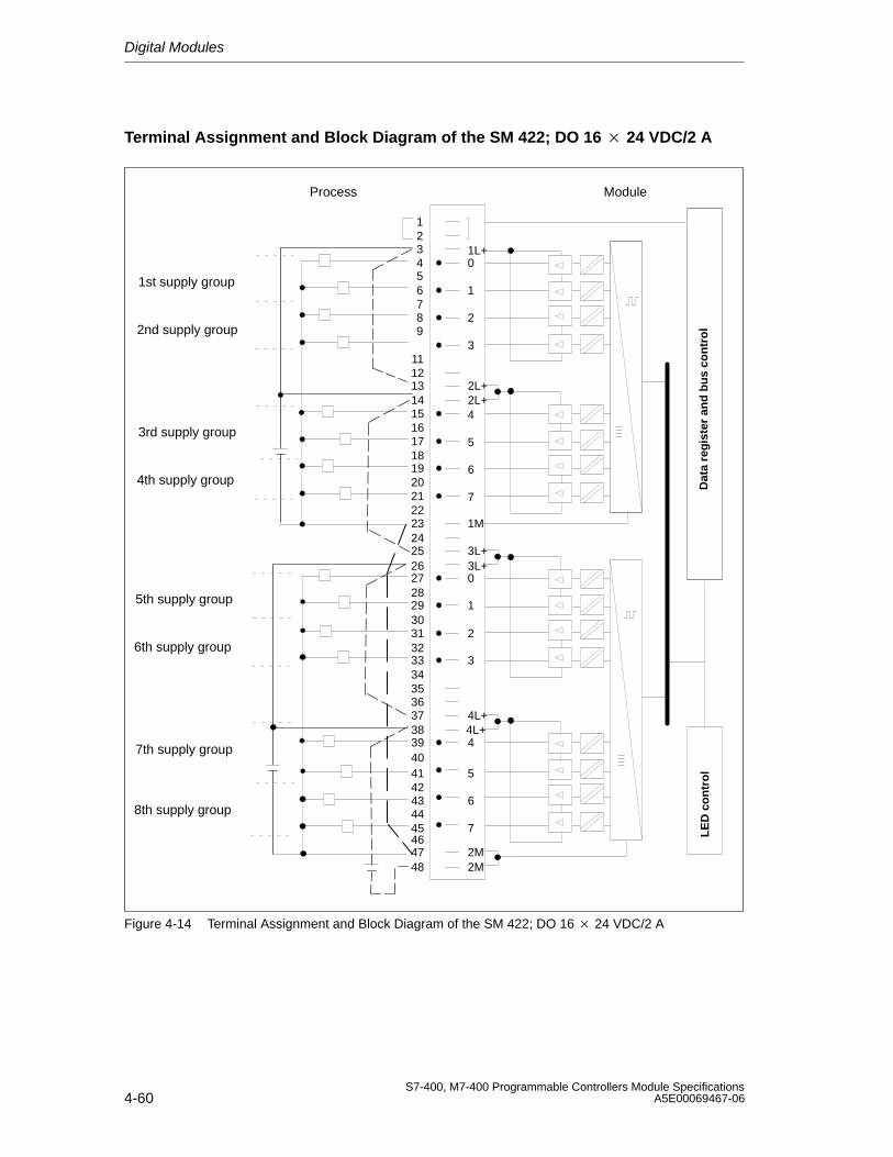
Digital Modules
4-60S7-400, M7-400 Programmable Controllers Module Specifications
A5E00069467-06
Terminal Assignment and Block Diagram of the SM 422; DO 16 24 VDC/2 A
Dat
a re
gis
ter
and
bu
s co
ntr
ol
LE
D c
on
tro
l
123456789
1112131415161718192021222324252627282930313233343536373839404142434445464748
1
2
0
3
1L+
5
6
4
7
5
6
4
7
1
2
0
3
2M
2L+2L+
1M
3L+3L+
2M
4L+4L+
Process Module
1st supply group
2nd supply group
3rd supply group
4th supply group
5th supply group
6th supply group
7th supply group
8th supply group
Figure 4-14 Terminal Assignment and Block Diagram of the SM 422; DO 16 24 VDC/2 A
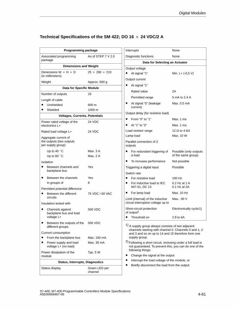
Digital Modules
4-61S7-400, M7-400 Programmable Controllers Module SpecificationsA5E00069467-06
Technical Specifications of the SM 422; DO 16 24 VDC/2 A
Programming package
Associated programmingpackage
As of STEP 7 V 2.0
Dimensions and Weight
Dimensions W H D (in millimeters)
25 290 210
Weight Approx. 600 g
Data for Specific Module
Number of outputs 16
Length of cable
• Unshielded
• Shielded
600 m
1000 m
Voltages, Currents, Potentials
Power rated voltage of theelectronics L+
24 VDC
Rated load voltage L+ 24 VDC
Aggregate current ofthe outputs (two outputsper supply group)
Up to 40 C
Up to 60 C
Max. 3 A
Max. 2 A
Isolation
• Between channels andbackplane bus
Yes
• Between the channels
In groups of
Yes
8
Permitted potential difference
• Between the differentcircuits
75 VDC / 60 VAC
Insulation tested with
• Channels againstbackplane bus and loadvoltage L+
500 VDC
• Between the outputs of thedifferent groups
500 VDC
Current consumption
• From the backplane bus
• Power supply and loadvoltage L+ (no load)
Max. 160 mA
Max. 30 mA
Power dissipation of themodule
Typ. 5 W
Status, Interrupts, Diagnostics
Status display Green LED perchannel
Interrupts None
Diagnostic functions None
Data for Selecting an Actuator
Output voltage
• At signal “1” Min. L+ (-0,5 V)
Output current
• At signal “1”
Rated value 2A
Permitted range 5 mA to 2.4 A
• At signal “0” (leakagecurrent)
Max. 0.5 mA
Output delay (for resistive load)
• From “0” to “1” Max. 1 ms
• At “1” to “0” Max. 1 ms
Load resistor range 12 to 4 k
Lamp load Max. 10 W
Parallel connection of 2 outputs
• For redundant triggering ofa load
Possible (only outputsof the same group)
• To increase performance Not possible
Triggering a digital input Possible
Switch rate
• For resistive load
• For inductive load to IEC947-51, DC 13
100 Hz
0.2 Hz at 1 A0.1 Hz at 2A
• For lamp load Max. 10 Hz
Limit (internal) of the inductivecircuit interruption voltage up to
Max. -30 V
Short-circuit protection of output1
• Threshold on
Electronically cyclic1)
2.8 to 6A
1) A supply group always consists of two adjacentchannels starting with channel 0. Channels 0 and 1, 2and 3 and so on up to 14 and 15 therefore form onesupply group.
2) Following a short circuit, reclosing under a full load is not guaranteed. To prevent this, you can do one of the following things:
• Change the signal at the output
• Interrupt the load voltage of the module, or
• Briefly disconnect the load from the output
Digital Modules
4-62S7-400, M7-400 Programmable Controllers Module Specifications
A5E00069467-06
4.17 Digital Output Module SM 422;DO 16 24 VDC/2 A; (6ES7422-1BH11-0AA0)
Characteristics
The digital output module SM 422; DO 16 24 VDC/2 A has the followingfeatures.
• 16 outputs, isolated in two groups of 8
• 2 A output current
• 24 VDC rated load voltage
The status LEDs also indicate the system status even when the front connector isnot inserted.
A Note about Commissioning
The following technical feature applies to the digital output module SM 422; DO 16 24 VDC/2 A with the order number 6ES7 422-1BH11-0AA0 but not to thedigital output module SM 422; DO 16 24 VDC/2 A with the order number 6ES7 422-1BH10-0AA0:
To commission the module, it is no longer necessary to apply load voltage (1L+and 3L+, for example,) to each group of 8 outputs. The module is fully operativeeven if only one group is supplied with L+.
Note
It is no longer possible to switch off all the outputs by disconnecting a single L+supply as might have been the case with the previous module(6ES7 422-1BH10-0AA0)L+.
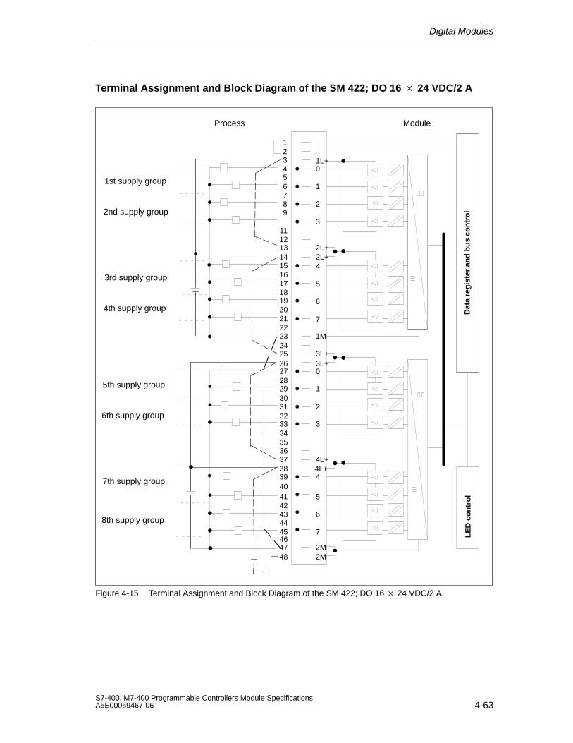
Digital Modules
4-63S7-400, M7-400 Programmable Controllers Module SpecificationsA5E00069467-06
Terminal Assignment and Block Diagram of the SM 422; DO 16 24 VDC/2 A
Dat
a re
gis
ter
and
bu
s co
ntr
ol
LE
D c
on
tro
l
123456789
1112131415161718192021222324252627282930313233343536373839404142434445464748
1
2
0
3
1L+
5
6
4
7
5
6
4
7
1
2
0
3
2M
2L+2L+
1M
3L+3L+
2M
4L+4L+
Process Module
1st supply group
2nd supply group
3rd supply group
4th supply group
5th supply group
6th supply group
7th supply group
8th supply group
Figure 4-15 Terminal Assignment and Block Diagram of the SM 422; DO 16 24 VDC/2 A
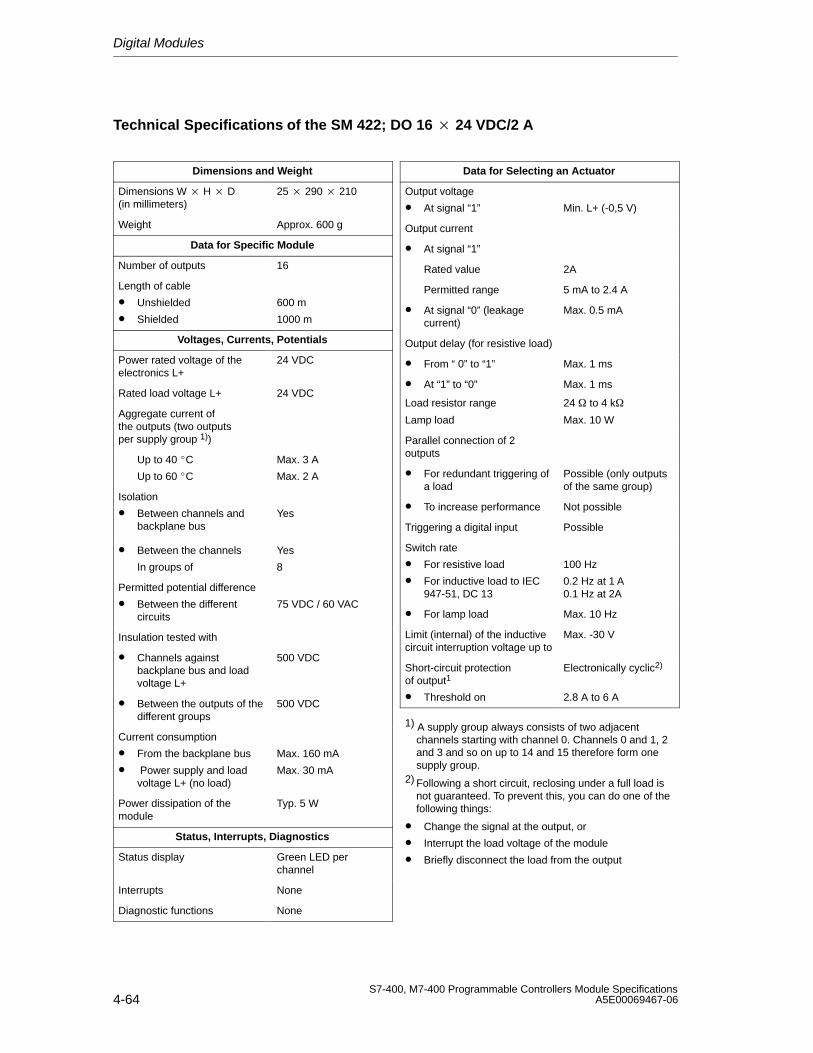
Digital Modules
4-64S7-400, M7-400 Programmable Controllers Module Specifications
A5E00069467-06
Technical Specifications of the SM 422; DO 16 24 VDC/2 A
Dimensions and Weight
Dimensions W H D (in millimeters)
25 290 210
Weight Approx. 600 g
Data for Specific Module
Number of outputs 16
Length of cable
• Unshielded
• Shielded
600 m
1000 m
Voltages, Currents, Potentials
Power rated voltage of theelectronics L+
24 VDC
Rated load voltage L+ 24 VDC
Aggregate current ofthe outputs (two outputsper supply group 1))
Up to 40 C
Up to 60 C
Max. 3 A
Max. 2 A
Isolation
• Between channels andbackplane bus
Yes
• Between the channels
In groups of
Yes
8
Permitted potential difference
• Between the differentcircuits
75 VDC / 60 VAC
Insulation tested with
• Channels againstbackplane bus and loadvoltage L+
500 VDC
• Between the outputs of thedifferent groups
500 VDC
Current consumption
• From the backplane bus
• Power supply and loadvoltage L+ (no load)
Max. 160 mA
Max. 30 mA
Power dissipation of themodule
Typ. 5 W
Status, Interrupts, Diagnostics
Status display Green LED perchannel
Interrupts None
Diagnostic functions None
Data for Selecting an Actuator
Output voltage
• At signal “1” Min. L+ (-0,5 V)
Output current
• At signal “1”
Rated value 2A
Permitted range 5 mA to 2.4 A
• At signal “0” (leakagecurrent)
Max. 0.5 mA
Output delay (for resistive load)
• From “ 0” to “1” Max. 1 ms
• At “1” to “0” Max. 1 ms
Load resistor range 24 to 4 k
Lamp load Max. 10 W
Parallel connection of 2 outputs
• For redundant triggering ofa load
Possible (only outputsof the same group)
• To increase performance Not possible
Triggering a digital input Possible
Switch rate
• For resistive load
• For inductive load to IEC947-51, DC 13
100 Hz
0.2 Hz at 1 A0.1 Hz at 2A
• For lamp load Max. 10 Hz
Limit (internal) of the inductivecircuit interruption voltage up to
Max. -30 V
Short-circuit protection of output1
• Threshold on
Electronically cyclic2)
2.8 A to 6 A
1) A supply group always consists of two adjacentchannels starting with channel 0. Channels 0 and 1, 2and 3 and so on up to 14 and 15 therefore form onesupply group.
2) Following a short circuit, reclosing under a full load is not guaranteed. To prevent this, you can do one of the following things:
• Change the signal at the output, or
• Interrupt the load voltage of the module
• Briefly disconnect the load from the output
Digital Modules
4-65S7-400, M7-400 Programmable Controllers Module SpecificationsA5E00069467-06
4.18 Digital Output ModuleSM 422; DO 16 20-125 VDC/1.5 A;(6ES7422-5EH10-0AB0)
Characteristics
The SM 422; DO 16 20-125 VDC/1.5 A has the following features:
• 16 outputs, each channel is fused; reverse polarity protection and isolated ingroups of 8
• 1.5 A output current
• Rated load voltage 20 to 125 VDC
• Group error display for internal faults (INTF) and external faults (EXTF)
• Programmable diagnostics
• Programmable diagnostic interrupt
• Programmable substitute value output
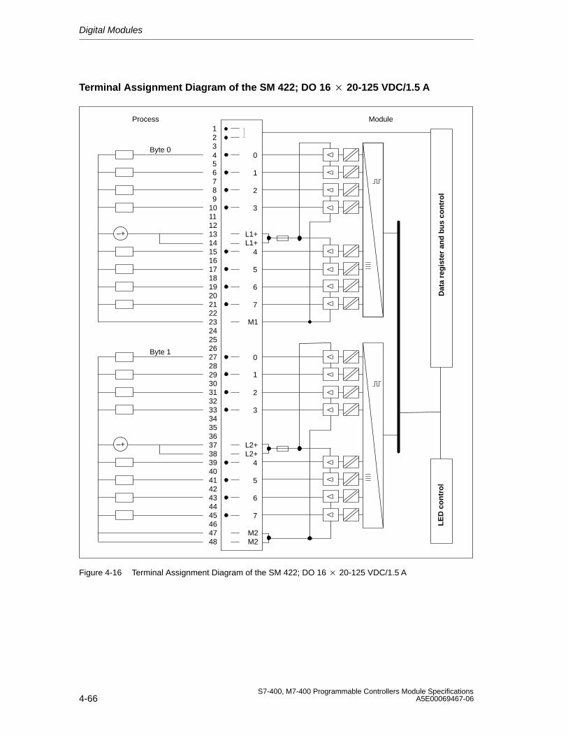
Digital Modules
4-66S7-400, M7-400 Programmable Controllers Module Specifications
A5E00069467-06
Terminal Assignment Diagram of the SM 422; DO 16 20-125 VDC/1.5 A
1234 0
Byte 0
56 178 29
10 311
13 L1+12
1415 41617 51819 62021 722
2423
262728293031323334
3635
383940414243444546
4847
25
37
0
1
2
3
4
5
6
7
M1
–+L1+
Byte 1
L2+
M2
–+L2+
M2
Process Module
Dat
a re
gis
ter
and
bu
s co
ntr
ol
LE
D c
on
tro
l
Figure 4-16 Terminal Assignment Diagram of the SM 422; DO 16 20-125 VDC/1.5 A
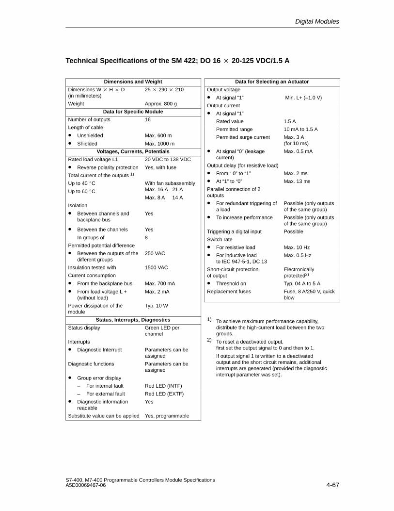
Digital Modules
4-67S7-400, M7-400 Programmable Controllers Module SpecificationsA5E00069467-06
Technical Specifications of the SM 422; DO 16 20-125 VDC/1.5 A
Dimensions and Weight
Dimensions W H D(in millimeters)
25 290 210
Weight Approx. 800 g
Data for Specific Module
Number of outputs 16
Length of cable
• Unshielded
• Shielded
Max. 600 m
Max. 1000 m
Voltages, Currents, Potentials
Rated load voltage L1
• Reverse polarity protection
20 VDC to 138 VDC
Yes, with fuse
Total current of the outputs 1)
Up to 40 C
Up to 60 C
With fan subassemblyMax. 16 A 21 A
Max. 8 A 14 A
Isolation
• Between channels andbackplane bus
Yes
• Between the channels
In groups of
Yes
8
Permitted potential difference
• Between the outputs of thedifferent groups
250 VAC
Insulation tested with 1500 VAC
Current consumption
• From the backplane bus
• From load voltage L +(without load)
Max. 700 mA
Max. 2 mA
Power dissipation of themodule
Typ. 10 W
Status, Interrupts, Diagnostics
Status display Green LED perchannel
Interrupts
• Diagnostic Interrupt Parameters can beassigned
Diagnostic functions Parameters can beassigned
• Group error display
– For internal fault Red LED (INTF)
– For external fault Red LED (EXTF)
• Diagnostic informationreadable
Yes
Substitute value can be applied Yes, programmable
Data for Selecting an Actuator
Output voltage
• At signal “1” Min. L+ (–1,0 V)
Output current
• At signal “1”
Rated value 1.5 A
Permitted range 10 mA to 1.5 A
Permitted surge current Max. 3 A (for 10 ms)
• At signal “0” (leakagecurrent)
Max. 0.5 mA
Output delay (for resistive load)
• From “ 0” to “1” Max. 2 ms
• At “1” to “0” Max. 13 ms
Parallel connection of 2 outputs
• For redundant triggering ofa load
Possible (only outputsof the same group)
• To increase performance Possible (only outputsof the same group)
Triggering a digital input Possible
Switch rate
• For resistive load Max. 10 Hz
• For inductive load to IEC 947-5-1, DC 13
Max. 0.5 Hz
Short-circuit protection of output
Electronicallyprotected2)
• Threshold on Typ. 04 A to 5 A
Replacement fuses Fuse, 8 A/250 V, quickblow
1) To achieve maximum performance capability, distribute the high-current load between the two groups.
2) To reset a deactivated output, first set the output signal to 0 and then to 1.
If output signal 1 is written to a deactivatedoutput and the short circuit remains, additional interrupts are generated (provided the diagnostic interrupt parameter was set).
Digital Modules
4-68S7-400, M7-400 Programmable Controllers Module Specifications
A5E00069467-06
Note
If the power supply is switched on by means of a mechanical contact, a voltagepulse may occur at the outputs. The transient pulse lasts a maximum of 0.5 ms.
Changing Fuses
!Warning
This can result in injury.
If you change a fuse without removing the front connector of the module, you couldbe injured by an electric shock.
Consequently, always remove the front connector before you change the fuse.
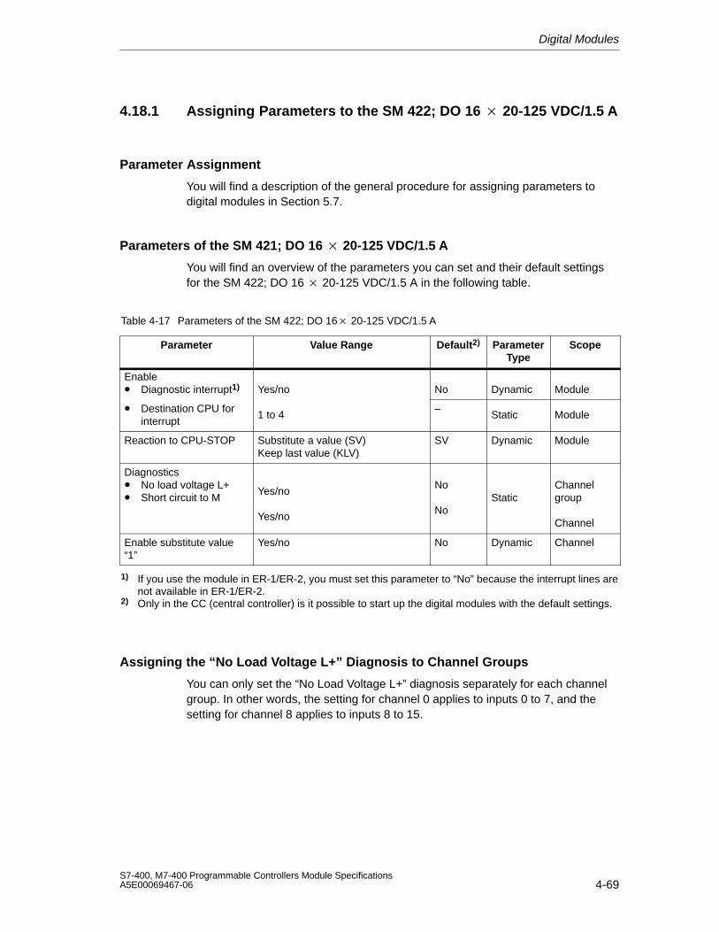
Digital Modules
4-69S7-400, M7-400 Programmable Controllers Module SpecificationsA5E00069467-06
4.18.1 Assigning Parameters to the SM 422; DO 16 20-125 VDC/1.5 A
Parameter Assignment
You will find a description of the general procedure for assigning parameters todigital modules in Section 5.7.
Parameters of the SM 421; DO 16 20-125 VDC/1.5 A
You will find an overview of the parameters you can set and their default settingsfor the SM 422; DO 16 20-125 VDC/1.5 A in the following table.
Table 4-17 Parameters of the SM 422; DO 16 20-125 VDC/1.5 A
Parameter Value Range Default2) ParameterType
Scope
Enable• Diagnostic interrupt1) Yes/no No Dynamic Module
• Destination CPU forinterrupt
1 to 4–
Static Module
Reaction to CPU-STOP Substitute a value (SV)Keep last value (KLV)
SV Dynamic Module
Diagnostics• No load voltage L+• Short circuit to M
Yes/no
Yes/no
No
NoStatic
Channelgroup
Channel
Enable substitute value“1”
Yes/no No Dynamic Channel
1) If you use the module in ER-1/ER-2, you must set this parameter to “No” because the interrupt lines arenot available in ER-1/ER-2.
2) Only in the CC (central controller) is it possible to start up the digital modules with the default settings.
Assigning the “No Load Voltage L+” Diagnosis to Channel Groups
You can only set the “No Load Voltage L+” diagnosis separately for each channelgroup. In other words, the setting for channel 0 applies to inputs 0 to 7, and thesetting for channel 8 applies to inputs 8 to 15.
Digital Modules
4-70S7-400, M7-400 Programmable Controllers Module Specifications
A5E00069467-06
4.19 Digital Output Module SM 422; DO 32 24 VDC/0.5 A;(6ES7422-1BL00-0AA0)
Characteristics
The SM 422; DO 32 x 24 VDC/0.5 A has the following features:
• 32 outputs, isolated in a group of 32
• Power is supplied to 8 channels in groups.
• A supply group always consists of eight adjacent channels starting with channel0. Channels 0 to 7, 8 to 15, 16 to 23 and 24 to 32 therefore form one supplygroup
• Each of these supply groups can be switched off separately by isolating L+,however you have to take note of the common ground connection.
• 0.5 A output current
• 24 VDC rated load voltage
The status LEDs also indicate the system status even when the front connector isnot inserted.
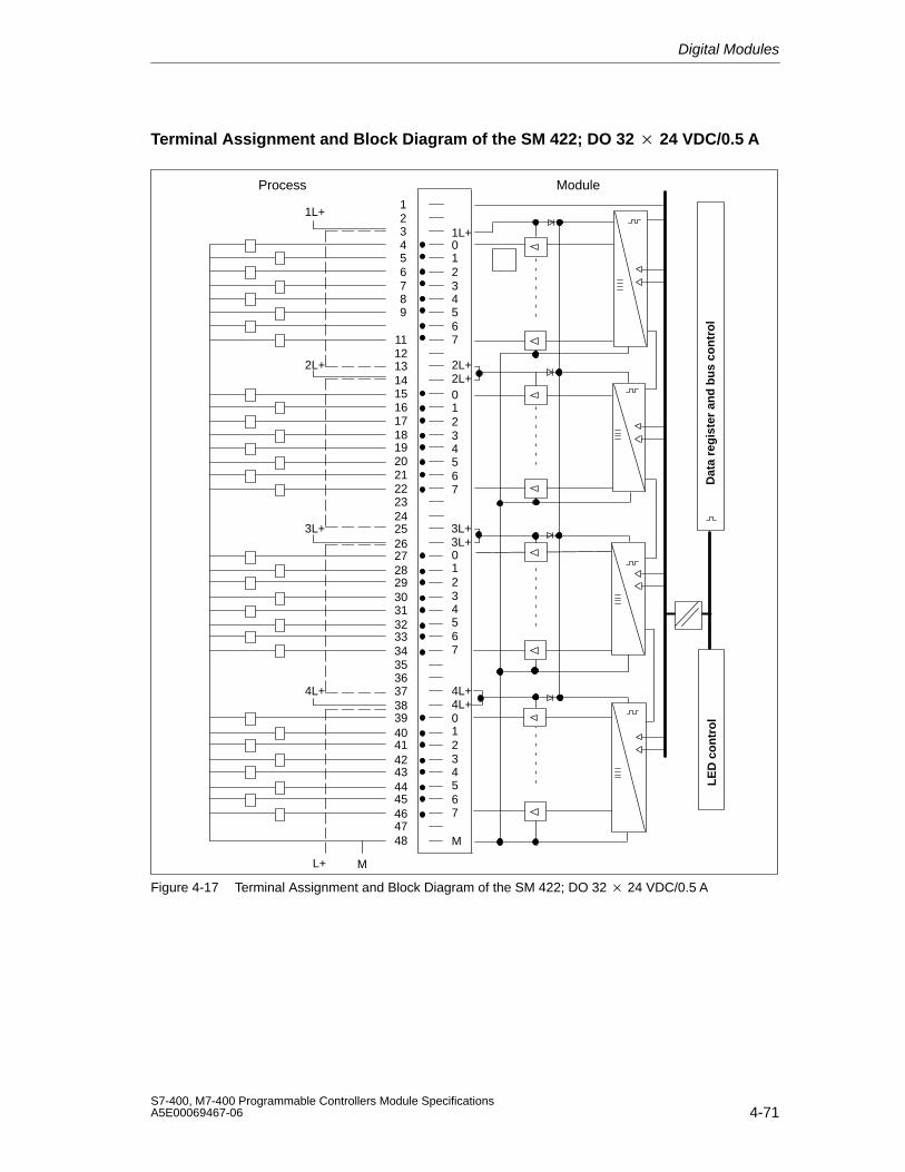
Digital Modules
4-71S7-400, M7-400 Programmable Controllers Module SpecificationsA5E00069467-06
Terminal Assignment and Block Diagram of the SM 422; DO 32 24 VDC/0.5 A
L+
123456789
1112131415161718192021222324252627282930313233343536373839404142434445464748
12
4
7
0
3
56
12
4
7
0
3
56
12
4
7
0
3
56
12
4
7
0
3
56
M
1L+
2L+2L+
3L+3L+
4L+4L+
3L+
2L+
4L+
1L+
M
Dat
a re
gis
ter
and
bu
s co
ntr
ol
LE
D c
on
tro
l
Process Module
Figure 4-17 Terminal Assignment and Block Diagram of the SM 422; DO 32 24 VDC/0.5 A
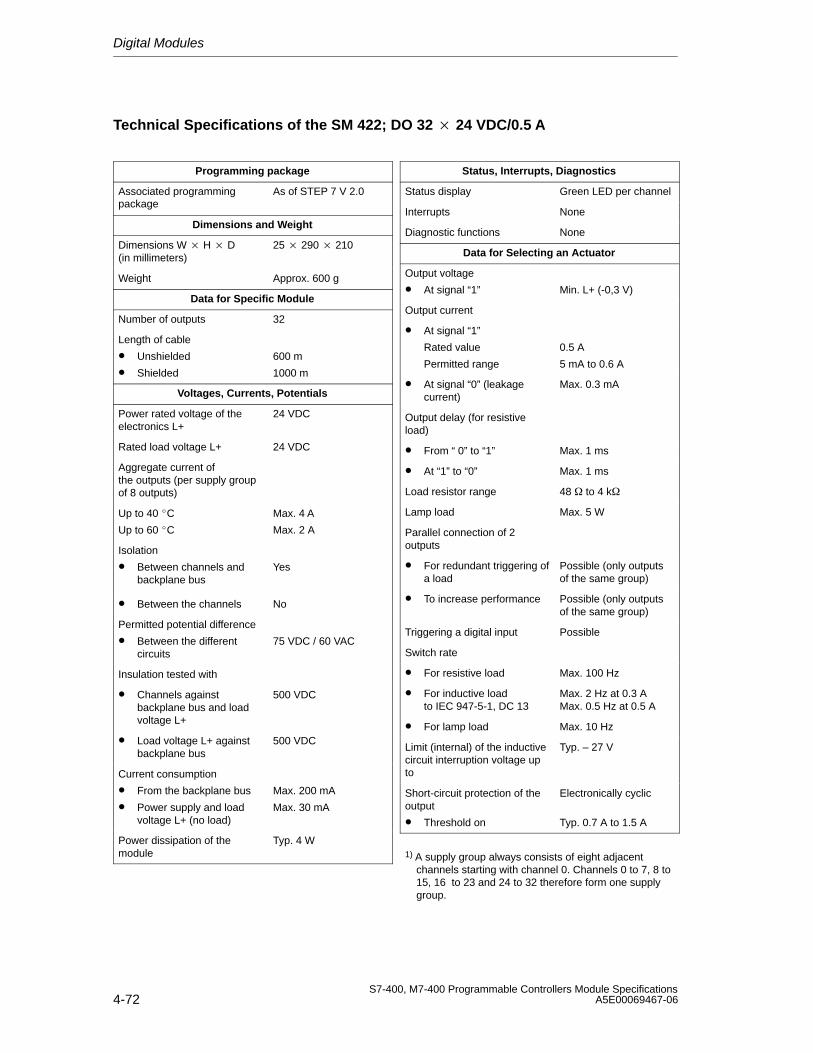
Digital Modules
4-72S7-400, M7-400 Programmable Controllers Module Specifications
A5E00069467-06
Technical Specifications of the SM 422; DO 32 24 VDC/0.5 A
Programming package
Associated programmingpackage
As of STEP 7 V 2.0
Dimensions and Weight
Dimensions W H D(in millimeters)
25 290 210
Weight Approx. 600 g
Data for Specific Module
Number of outputs 32
Length of cable
• Unshielded
• Shielded
600 m
1000 m
Voltages, Currents, Potentials
Power rated voltage of theelectronics L+
24 VDC
Rated load voltage L+ 24 VDC
Aggregate current ofthe outputs (per supply groupof 8 outputs)
Up to 40 C
Up to 60 C
Max. 4 A
Max. 2 A
Isolation
• Between channels andbackplane bus
Yes
• Between the channels No
Permitted potential difference
• Between the differentcircuits
75 VDC / 60 VAC
Insulation tested with
• Channels againstbackplane bus and loadvoltage L+
500 VDC
• Load voltage L+ againstbackplane bus
500 VDC
Current consumption
• From the backplane bus
• Power supply and loadvoltage L+ (no load)
Max. 200 mA
Max. 30 mA
Power dissipation of themodule
Typ. 4 W
Status, Interrupts, Diagnostics
Status display Green LED per channel
Interrupts None
Diagnostic functions None
Data for Selecting an Actuator
Output voltage
• At signal “1” Min. L+ (-0,3 V)
Output current
• At signal “1”
Rated value
Permitted range
0.5 A
5 mA to 0.6 A
• At signal “0” (leakagecurrent)
Max. 0.3 mA
Output delay (for resistiveload)
• From “ 0” to “1” Max. 1 ms
• At “1” to “0” Max. 1 ms
Load resistor range 48 to 4 k
Lamp load Max. 5 W
Parallel connection of 2 outputs
• For redundant triggering ofa load
Possible (only outputsof the same group)
• To increase performance Possible (only outputsof the same group)
Triggering a digital input Possible
Switch rate
• For resistive load Max. 100 Hz
• For inductive load to IEC 947-5-1, DC 13
Max. 2 Hz at 0.3 AMax. 0.5 Hz at 0.5 A
• For lamp load Max. 10 Hz
Limit (internal) of the inductivecircuit interruption voltage upto
Typ. – 27 V
Short-circuit protection of theoutput
• Threshold on
Electronically cyclic
Typ. 0.7 A to 1.5 A
1) A supply group always consists of eight adjacentchannels starting with channel 0. Channels 0 to 7, 8 to15, 16 to 23 and 24 to 32 therefore form one supplygroup.
Digital Modules
4-73S7-400, M7-400 Programmable Controllers Module SpecificationsA5E00069467-06
4.20 Digital Output Module SM 422; DO 32 24 VDC/0.5 A;(6ES7422-7BL00-0AB0)
Characteristics
The digital output module SM 422; DO 32 24 VDC/0.5 A has the followingfeatures:
• 32 outputs, fused and isolated in groups of 8
• 0.5 A output current
• 24 VDC rated load voltage
• Group error display for internal faults (INTF) and external faults (EXTF)
• Programmable diagnostics
• Programmable diagnostic interrupt
• Programmable substitute value output
The status LEDs also indicate the system status even when the front connector isnot inserted.
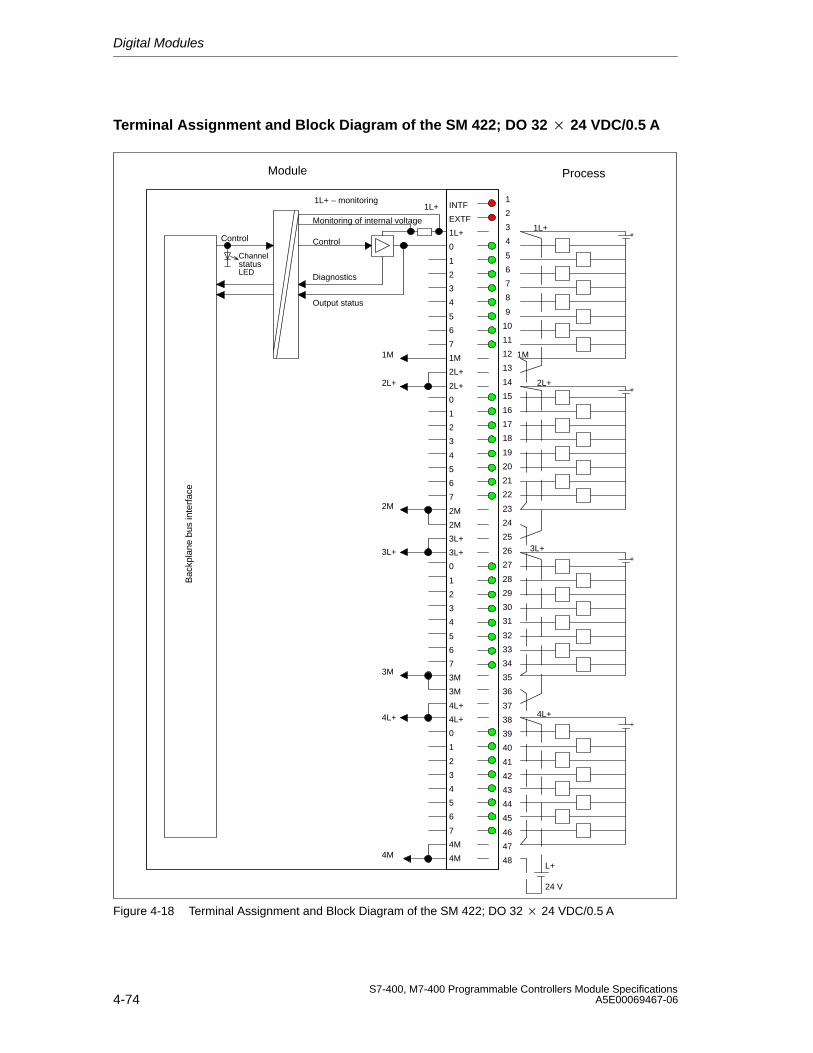
Digital Modules
4-74S7-400, M7-400 Programmable Controllers Module Specifications
A5E00069467-06
Terminal Assignment and Block Diagram of the SM 422; DO 32 24 VDC/0.5 A
INTF
EXTF
1L+
0
1
2
3
4
5
6
7
1M
2L+
2L+
0
1
2
3
4
5
6
7
2M
2M
3L+
3L+
0
1
2
3
4
5
6
7
3M
3M
4L+
4L+
0
1
2
3
4
5
6
7
4M
4M
1L+
1L+
2L+
Bac
kpla
ne b
us in
terf
ace
1M
2L+
3L+
4L+
3M
4M
2M
1M
+
+
+
+
3L+
4L+
Control
Diagnostics
Output status
1L+ – monitoring
Monitoring of internal voltage
Control
ChannelstatusLED
L+
24 V
1
2
3
4
5
6
7
8
9
10
11
12
13
14
15
16
17
18
19
20
21
22
23
24
25
26
27
28
29
30
31
32
33
34
35
36
37
38
39
40
41
42
43
44
45
46
47
48
ProcessModule
Figure 4-18 Terminal Assignment and Block Diagram of the SM 422; DO 32 24 VDC/0.5 A
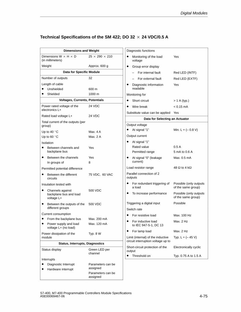
Digital Modules
4-75S7-400, M7-400 Programmable Controllers Module SpecificationsA5E00069467-06
Technical Specifications of the SM 422; DO 32 24 VDC/0.5 A
Dimensions and Weight
Dimensions W H D(in millimeters)
25 290 210
Weight Approx. 600 g
Data for Specific Module
Number of outputs 32
Length of cable
• Unshielded
• Shielded
600 m
1000 m
Voltages, Currents, Potentials
Power rated voltage of theelectronics L+
24 VDC
Rated load voltage L+ 24 VDC
Total current of the outputs (pergroup)
Up to 40 C
Up to 60 C
Max. 4 A
Max. 2 A
Isolation
• Between channels andbackplane bus
Yes
• Between the channels
In groups of
Yes
8
Permitted potential difference
• Between the differentcircuits
75 VDC, 60 VAC
Insulation tested with
• Channels againstbackplane bus and loadvoltage L+
500 VDC
• Between the outputs of thedifferent groups
500 VDC
Current consumption
• From the backplane bus
• Power supply and loadvoltage L+ (no load)
Max. 200 mA
Max. 120 mA
Power dissipation of themodule
Typ. 8 W
Status, Interrupts, Diagnostics
Status display Green LED perchannel
Interrupts
• Diagnostic Interrupt
• Hardware interrupt
Parameters can beassigned
Parameters can beassigned
Diagnostic functions
• Monitoring of the loadvoltage
Yes
• Group error display
– For internal fault Red LED (INTF)
– For external fault Red LED (EXTF)
• Diagnostic informationreadable
Yes
Monitoring for
• Short circuit > 1 A (typ.)
• Wire break < 0.15 mA
Substitute value can be applied Yes
Data for Selecting an Actuator
Output voltage
• At signal “1” Min. L + (– 0.8 V)
Output current
• At signal “1”
Rated value
Permitted range
0.5 A
5 mA to 0.6 A
• At signal “0” (leakagecurrent)
Max. 0.5 mA
Load resistor range 48 to 4 k
Parallel connection of 2 outputs
• For redundant triggering ofa load
Possible (only outputsof the same group)
• To increase performance Possible (only outputsof the same group)
Triggering a digital input Possible
Switch rate
• For resistive load Max. 100 Hz
• For inductive load to IEC 947-5-1, DC 13
Max. 2 Hz
• For lamp load Max. 2 Hz
Limit (internal) of the inductivecircuit interruption voltage up to
Typ. L + (– 45 V)
Short-circuit protection of theoutput
• Threshold on
Electronically cyclic
Typ. 0.75 A to 1.5 A
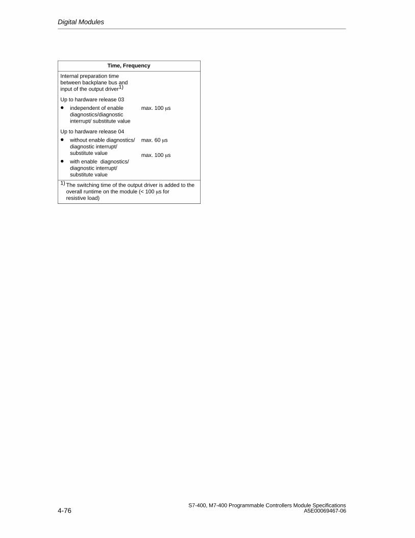
Digital Modules
4-76S7-400, M7-400 Programmable Controllers Module Specifications
A5E00069467-06
Time, Frequency
Internal preparation timebetween backplane bus andinput of the output driver1)
Up to hardware release 03
• independent of enablediagnostics/diagnosticinterrupt/ substitute value
max. 100 s
Up to hardware release 04
• without enable diagnostics/diagnostic interrupt/substitute value
• with enable diagnostics/diagnostic interrupt/substitute value
max. 60 s
max. 100 s
1) The switching time of the output driver is added to the overall runtime on the module (< 100 s forresistive load)
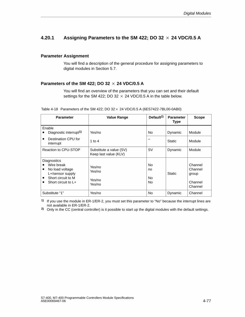
Digital Modules
4-77S7-400, M7-400 Programmable Controllers Module SpecificationsA5E00069467-06
4.20.1 Assigning Parameters to the SM 422; DO 32 24 VDC/0.5 A
Parameter Assignment
You will find a description of the general procedure for assigning parameters todigital modules in Section 5.7.
Parameters of the SM 422; DO 32 24 VDC/0.5 A
You will find an overview of the parameters that you can set and their defaultsettings for the SM 422; DO 32 24 VDC/0.5 A in the table below.
Table 4-18 Parameters of the SM 422; DO 32 24 VDC/0.5 A (6ES7422-7BL00-0AB0)
Parameter Value Range Default2) ParameterType
Scope
Enable• Diagnostic interrupt1) Yes/no No Dynamic Module
• Destination CPU forinterrupt
1 to 4–
Static Module
Reaction to CPU-STOP Substitute a value (SV)Keep last value (KLV)
SV Dynamic Module
Diagnostics• Wire break• No load voltage
L+/sensor supply• Short circuit to M• Short circuit to L+
Yes/noYes/no
Yes/noYes/no
Nono
NoNo
Static
ChannelChannelgroup
ChannelChannel
Substitute “1” Yes/no No Dynamic Channel
1) If you use the module in ER-1/ER-2, you must set this parameter to “No” because the interrupt lines arenot available in ER-1/ER-2.
2) Only in the CC (central controller) is it possible to start up the digital modules with the default settings.
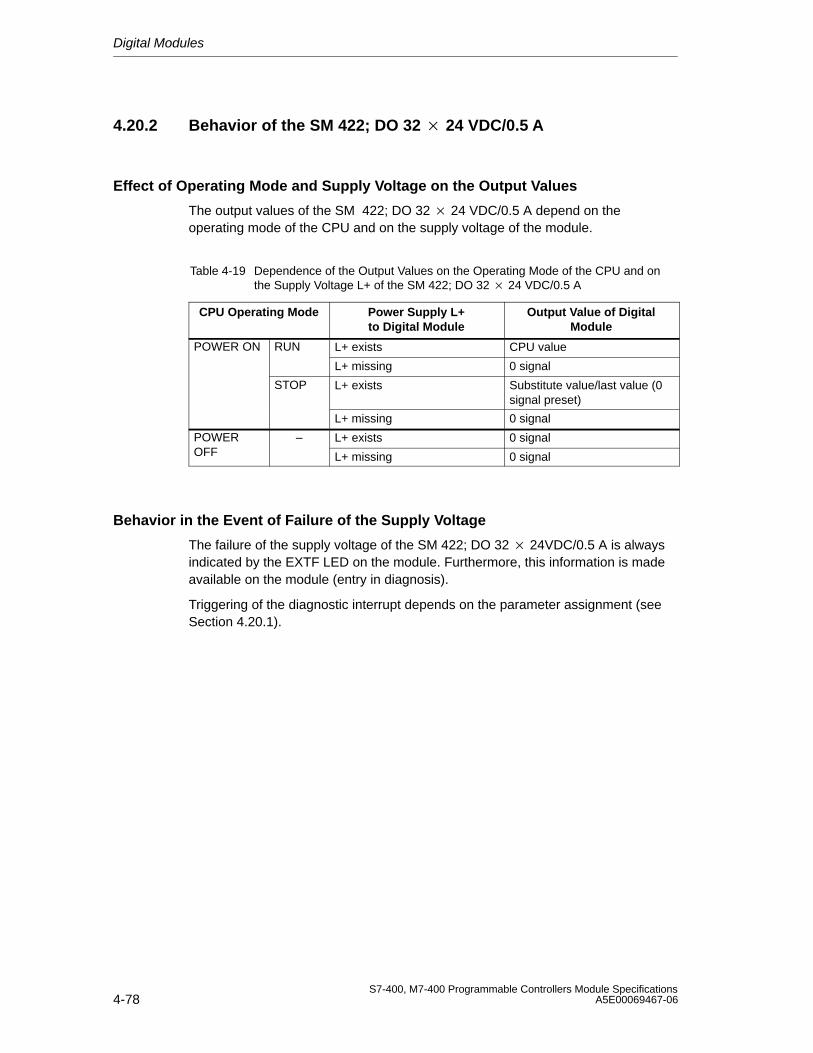
Digital Modules
4-78S7-400, M7-400 Programmable Controllers Module Specifications
A5E00069467-06
4.20.2 Behavior of the SM 422; DO 32 24 VDC/0.5 A
Effect of Operating Mode and Supply Voltage on the Output Values
The output values of the SM 422; DO 32 24 VDC/0.5 A depend on theoperating mode of the CPU and on the supply voltage of the module.
Table 4-19 Dependence of the Output Values on the Operating Mode of the CPU and onthe Supply Voltage L+ of the SM 422; DO 32 24 VDC/0.5 A
CPU Operating Mode Power Supply L+to Digital Module
Output Value of DigitalModule
POWER ON RUN L+ exists CPU value
L+ missing 0 signal
STOP L+ exists Substitute value/last value (0signal preset)
L+ missing 0 signal
POWER – L+ exists 0 signalOFF L+ missing 0 signal
Behavior in the Event of Failure of the Supply Voltage
The failure of the supply voltage of the SM 422; DO 32 24VDC/0.5 A is alwaysindicated by the EXTF LED on the module. Furthermore, this information is madeavailable on the module (entry in diagnosis).
Triggering of the diagnostic interrupt depends on the parameter assignment (seeSection 4.20.1).
Digital Modules
4-79S7-400, M7-400 Programmable Controllers Module SpecificationsA5E00069467-06
4.21 Digital Output Module SM 422;DO 8 120/230 VAC/5 A; (6ES7422-1FF00-0AA0)
Characteristics
The SM 422; DO 8 120/230 VAC/5 A has the following features:
• 8 outputs, isolated in groups of 1
• Output current 5 A
• 120/230 VAC rated load voltage
The status LEDs also indicate the system status even when the front connector isnot inserted.
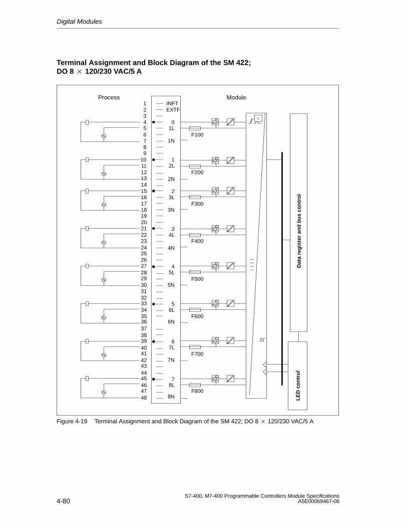
Digital Modules
4-80S7-400, M7-400 Programmable Controllers Module Specifications
A5E00069467-06
Terminal Assignment and Block Diagram of the SM 422; DO 8 120/230 VAC/5 A
123456789
101112131415161718192021222324252627282930313233343536373839404142434445464748
1L
1N
12L
0
7L
7N
78L
6
3L
3N
34L
2
5L
5N
56L
4 Dat
a re
gis
ter
and
bu
s co
ntr
ol
LE
D c
on
tro
l
t
F100
F200
F300
F400
F500
F600
F700
F800
6N
8N
2N
4N
INFTEXTF
Process Module
Figure 4-19 Terminal Assignment and Block Diagram of the SM 422; DO 8 120/230 VAC/5 A
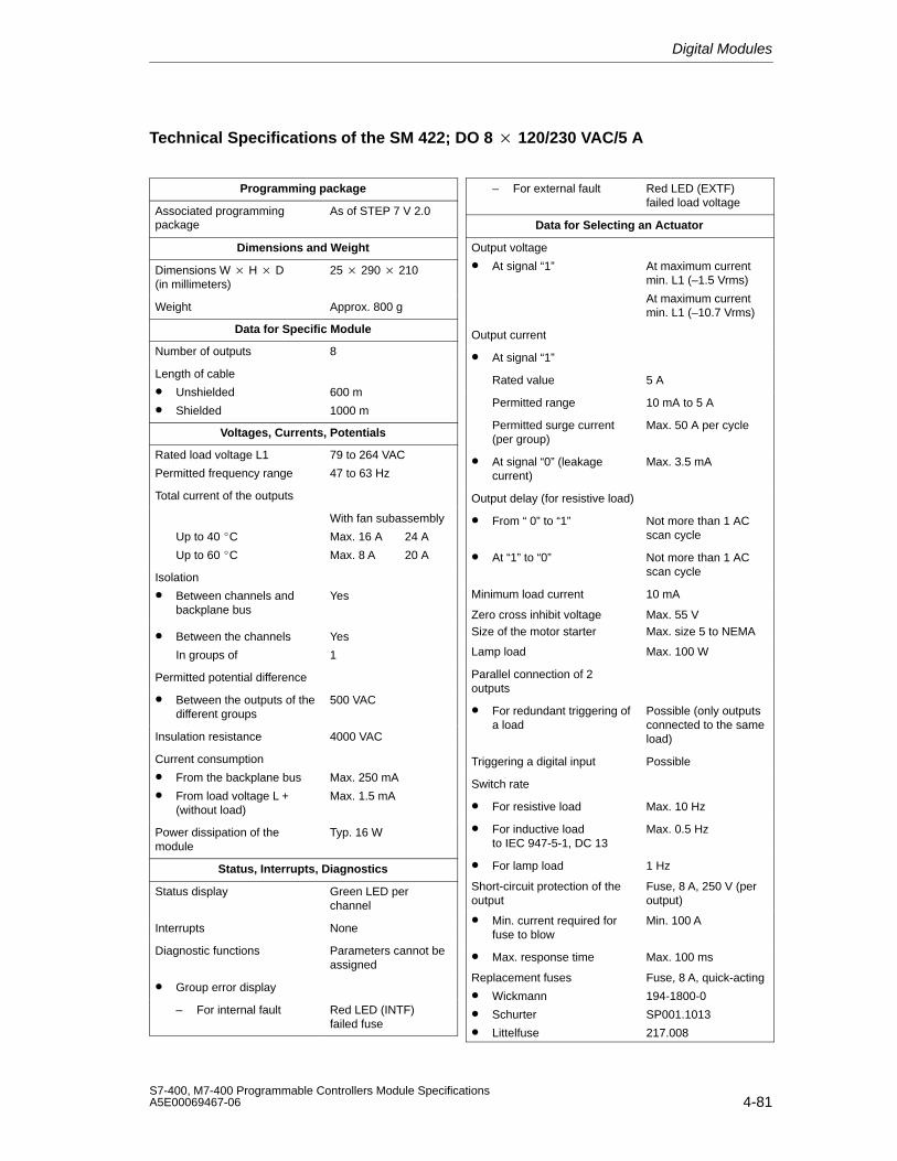
Digital Modules
4-81S7-400, M7-400 Programmable Controllers Module SpecificationsA5E00069467-06
Technical Specifications of the SM 422; DO 8 120/230 VAC/5 A
Programming package
Associated programmingpackage
As of STEP 7 V 2.0
Dimensions and Weight
Dimensions W H D(in millimeters)
25 290 210
Weight Approx. 800 g
Data for Specific Module
Number of outputs 8
Length of cable
• Unshielded
• Shielded
600 m
1000 m
Voltages, Currents, Potentials
Rated load voltage L1
Permitted frequency range
79 to 264 VAC
47 to 63 Hz
Total current of the outputs
Up to 40 C
Up to 60 C
With fan subassembly
Max. 16 A 24 A
Max. 8 A 20 A
Isolation
• Between channels andbackplane bus
Yes
• Between the channels
In groups of
Yes
1
Permitted potential difference
• Between the outputs of thedifferent groups
500 VAC
Insulation resistance 4000 VAC
Current consumption
• From the backplane bus
• From load voltage L +(without load)
Max. 250 mA
Max. 1.5 mA
Power dissipation of themodule
Typ. 16 W
Status, Interrupts, Diagnostics
Status display Green LED perchannel
Interrupts None
Diagnostic functions Parameters cannot beassigned
• Group error display
– For internal fault Red LED (INTF) failed fuse
– For external fault Red LED (EXTF)failed load voltage
Data for Selecting an Actuator
Output voltage
• At signal “1” At maximum currentmin. L1 (–1.5 Vrms)
At maximum currentmin. L1 (–10.7 Vrms)
Output current
• At signal “1”
Rated value 5 A
Permitted range 10 mA to 5 A
Permitted surge current(per group)
Max. 50 A per cycle
• At signal “0” (leakagecurrent)
Max. 3.5 mA
Output delay (for resistive load)
• From “ 0” to “1” Not more than 1 ACscan cycle
• At “1” to “0” Not more than 1 ACscan cycle
Minimum load current 10 mA
Zero cross inhibit voltage Max. 55 VSize of the motor starter Max. size 5 to NEMA
Lamp load Max. 100 W
Parallel connection of 2 outputs
• For redundant triggering ofa load
Possible (only outputsconnected to the sameload)
Triggering a digital input Possible
Switch rate
• For resistive load Max. 10 Hz
• For inductive load to IEC 947-5-1, DC 13
Max. 0.5 Hz
• For lamp load 1 Hz
Short-circuit protection of theoutput
Fuse, 8 A, 250 V (peroutput)
• Min. current required forfuse to blow
Min. 100 A
• Max. response time Max. 100 ms
Replacement fuses
• Wickmann
• Schurter
• Littelfuse
Fuse, 8 A, quick-acting
194-1800-0
SP001.1013
217.008
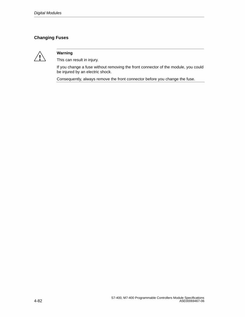
Digital Modules
4-82S7-400, M7-400 Programmable Controllers Module Specifications
A5E00069467-06
Changing Fuses
!Warning
This can result in injury.
If you change a fuse without removing the front connector of the module, you couldbe injured by an electric shock.
Consequently, always remove the front connector before you change the fuse.
Digital Modules
4-83S7-400, M7-400 Programmable Controllers Module SpecificationsA5E00069467-06
4.22 Digital Output Module SM 422; DO 16 120/230 VAC/2 A;(6ES7422-1FH00-0AA0)
Characteristics
The SM 422; DO 16 120/230 VAC/2 A has the following features:
• 16 outputs, isolated in groups of 4
• 2 A output current
• 120/230 VAC rated load voltage
The status LEDs also indicate the system status even when the front connector isnot inserted.
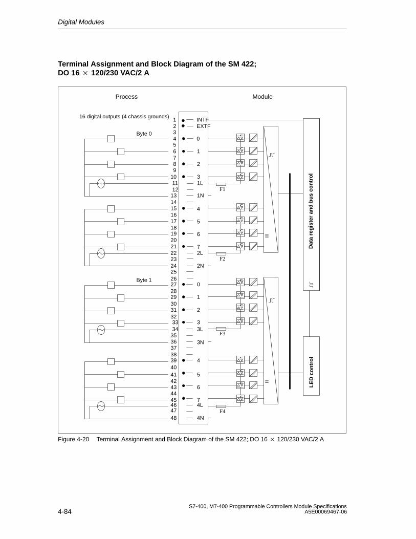
Digital Modules
4-84S7-400, M7-400 Programmable Controllers Module Specifications
A5E00069467-06
Terminal Assignment and Block Diagram of the SM 422; DO 16 120/230 VAC/2 A
Byte 0
16 digital outputs (4 chassis grounds)
Byte 1
1112
13141516171819202122232425262728293031323334
3536373839404142434445
4746
48
Dat
a re
gis
ter
and
bu
s co
ntr
ol
10
LE
D c
on
tro
l
F1
F2
F3
F4
123456789
1
2
0
3
5
6
4
7
5
6
4
7
1
2
0
3
4N
1N
1L
2L
3L
2N
4L
3N
INTFEXTF
Process Module
Figure 4-20 Terminal Assignment and Block Diagram of the SM 422; DO 16 120/230 VAC/2 A
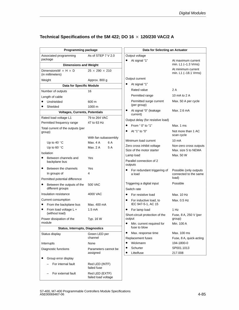
Digital Modules
4-85S7-400, M7-400 Programmable Controllers Module SpecificationsA5E00069467-06
Technical Specifications of the SM 422; DO 16 120/230 VAC/2 A
Programming package
Associated programmingpackage
As of STEP 7 V 2.0
Dimensions and Weight
DimensionsW H D(in millimeters)
25 290 210
Weight Approx. 800 g
Data for Specific Module
Number of outputs 16
Length of cable
• Unshielded
• Shielded
600 m
1000 m
Voltages, Currents, Potentials
Rated load voltage L1
Permitted frequency range
79 to 264 VAC
47 to 63 Hz
Total current of the outputs (pergroup)
Up to 40 C
Up to 60 C
With fan subassembly
Max. 4 A 6 A
Max. 2 A 5 A
Isolation
• Between channels andbackplane bus
Yes
• Between the channels
In groups of
Yes
4
Permitted potential difference
• Between the outputs of thedifferent groups
500 VAC
Insulation resistance 4000 VAC
Current consumption
• From the backplane bus
• From load voltage L +(without load)
Max. 400 mA
1.5 mA
Power dissipation of themodule
Typ. 16 W
Status, Interrupts, Diagnostics
Status display Green LED perchannel
Interrupts None
Diagnostic functions Parameters cannot beassigned
• Group error display
– For internal fault Red LED (INTF) failed fuse
– For external fault Red LED (EXTF)failed load voltage
Data for Selecting an Actuator
Output voltage
• At signal “1” At maximum currentmin. L1 (–1.3 Vrms)
At minimum currentmin. L1 (–18.1 Vrms)
Output current
• At signal “1”
Rated value 2 A
Permitted range 10 mA to 2 A
Permitted surge current(per group)
Max. 50 A per cycle
• At signal “0” (leakagecurrent)
Max. 2.6 mA
Output delay (for resistive load)
• From “ 0” to “1” Max. 1 ms
• At “1” to “0” Not more than 1 ACscan cycle
Minimum load current 10 mA
Zero cross inhibit voltage Non-zero cross outputsSize of the motor starter Max. size 5 to NEMA
Lamp load Max. 50 W
Parallel connection of 2 outputs
• For redundant triggering ofa load
Possible (only outputsconnected to the sameload)
Triggering a digital input Possible
Switch rate
• For resistive load Max. 10 Hz
• For inductive load, to IEC 947-5-1, AC 15
Max. 0.5 Hz
• For lamp load 1 Hz
Short-circuit protection of theoutput
Fuse, 8 A, 250 V (pergroup)
• Min. current required forfuse to blow
Min. 100 A
• Max. response time Max. 100 ms
Replacement fuses
• Wickmann
• Schurter
• Littelfuse
Fuse, 8 A, quick-acting
194-1800-0
SP001.1013
217.008

Digital Modules
4-86S7-400, M7-400 Programmable Controllers Module Specifications
A5E00069467-06
Changing Fuses
!Warning
This can result in injury.
If you change a fuse without removing the front connector of the module, you couldbe injured by an electric shock.
Consequently, always remove the front connector before you change the fuse.
Digital Modules
4-87S7-400, M7-400 Programmable Controllers Module SpecificationsA5E00069467-06
4.23 Digital Output Module SM 422;DO 16 20-120 VAC/2 A; (6ES7422-5EH00-0AB0)
Characteristics
The SM 422; DO 16 20-120 VAC/2 A has the following features:
• 16 outputs, isolated in groups of 1
• 2 A output current
• Rated load voltage 20 VAC to 120 VAC
• Group error display for internal faults (INTF) and external faults (EXTF)
• Programmable diagnostics
• Programmable diagnostic interrupt
• Programmable substitute value output
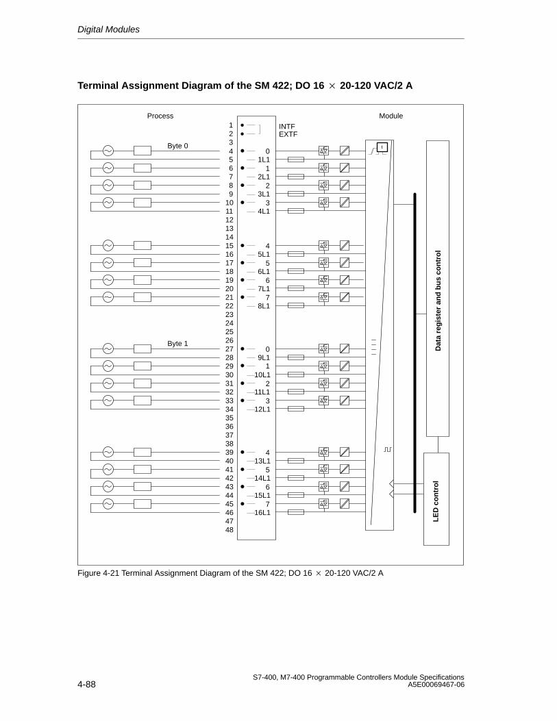
Digital Modules
4-88S7-400, M7-400 Programmable Controllers Module Specifications
A5E00069467-06
Terminal Assignment Diagram of the SM 422; DO 16 20-120 VAC/2 A
1234 0
Byte 0
56 178 29
10 311
13
1L1
12
1415 41617 51819 62021 722
2423
262728293031323334
3635
383940414243444546
4847
25
37
0
1
2
3
4
5
6
7
2L1
3L1
4L1
5L1
6L1
7L1
8L1
9L1
10L1
11L1
12L1
13L1
14L1
15L1
16L1
Byte 1
INTFEXTF
t
Process Module
Dat
a re
gis
ter
and
bu
s co
ntr
ol
LE
D c
on
tro
l
Figure 4-21 Terminal Assignment Diagram of the SM 422; DO 16 20-120 VAC/2 A
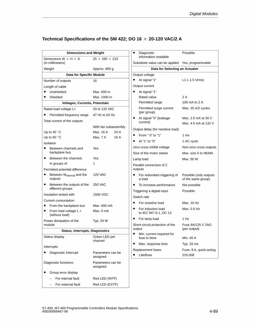
Digital Modules
4-89S7-400, M7-400 Programmable Controllers Module SpecificationsA5E00069467-06
Technical Specifications of the SM 422; DO 16 20-120 VAC/2 A
Dimensions and Weight
Dimensions W H D(in millimeters)
25 290 210
Weight Approx. 800 g
Data for Specific Module
Number of outputs 16
Length of cable
• Unshielded
• Shielded
Max. 600 m
Max. 1000 m
Voltages, Currents, Potentials
Rated load voltage L+ 20 to 132 VAC
• Permitted frequency range 47 Hz to 63 Hz
Total current of the outputs
Up to 40 C
Up to 60 C
With fan subassembly
Max. 16 A 24 A
Max. 7 A 16 A
Isolation
• Between channels andbackplane bus
Yes
• Between the channels
In groups of
Yes
1
Permitted potential difference
• Between Minternal and theoutputs
120 VAC
• Between the outputs of thedifferent groups
250 VAC
Insulation tested with 1500 VDC
Current consumption
• From the backplane bus
• From load voltage L +(without load)
Max. 600 mA
Max. 0 mA
Power dissipation of themodule
Typ. 20 W
Status, Interrupts, Diagnostics
Status display Green LED perchannel
Interrupts
• Diagnostic Interrupt Parameters can beassigned
Diagnostic functions Parameters can beassigned
• Group error display
– For internal fault Red LED (INTF)
– For external fault Red LED (EXTF)
• Diagnosticinformation readable
Possible
Substitute value can be applied Yes, programmable
Data for Selecting an Actuator
Output voltage
• At signal “1” L1 (–1.5 Vrms)
Output current
• At signal “1”
Rated value
Permitted range
2 A
100 mA to 2 A
Permitted surge current(per group)
Max. 20 A/2 cycles
• At signal “0” (leakagecurrent)
Max. 2.5 mA at 30 V
Max. 4.5 mA at 132 V
Output delay (for resistive load)
• From “ 0” to “1” 1 ms
• At “1” to “0” 1 AC cycle
Zero cross inhibit voltage Non-zero cross outputs
Size of the motor starter Max. size 5 to NEMA
Lamp load Max. 50 W
Parallel connection of 2 outputs
• For redundant triggering ofa load
Possible (only outputsof the same group)
• To increase performance Not possible
Triggering a digital input Possible
Switch rate
• For resistive load Max. 10 Hz
• For inductive load to IEC 947-5-1, DC 13
Max. 0.5 Hz
• For lamp load 1 Hz
Short-circuit protection of theoutput
• Min. current required forfuse to blow
Fuse 8A/125 V 2AG(per output)
Min. 40 A
• Max. response time Typ. 33 ms
Replacement fuses
• Littelfuse
Fuse, 8 A, quick-acting
225.008
Digital Modules
4-90S7-400, M7-400 Programmable Controllers Module Specifications
A5E00069467-06
Changing Fuses
!Warning
This can result in injury.
If you change a fuse without removing the front connector of the module, you couldbe injured by an electric shock.
Consequently, always remove the front connector before you change the fuse.
4.23.1 Assigning Parameters to the SM 422; DO 16 20-120 VAC/2 A
Parameter Assignment
You will find a description of the general procedure for assigning parameters todigital modules in Section 5.7.
Parameters of the SM 422; DO 16 20-120 VAC/2 A
You will find an overview of the parameters you can set and their default settingsfor the SM 422; DO 16 20-120 VAC/2 A in the following table.
Table 4-20 Parameters of the SM 422; DO 16 20-120 VAC/2 A
Parameter Value Range Default2) ParameterType
Scope
Enable• Diagnostic interrupt1) Yes/no No Dynamic Module
• Destination CPU forinterrupt
1 to 4–
Static Module
Reaction to CPU STOP Substitute a value (SV)Keep last value (KLV)
SV Dynamic Module
Diagnostics• Fuse blown Yes/no No Static Channel
Enable substitute value“1”
Yes/no No Dynamic Channel
1) If you use the module in ER-1/ER-2, you must set this parameter to “No” because the interrupt lines arenot available in ER-1/ER-2.
2) Only in the CC (central controller) is it possible to start up the digital modules with the default settings.
Digital Modules
4-91S7-400, M7-400 Programmable Controllers Module SpecificationsA5E00069467-06
4.24 Relay Output Module SM 422;DO 16 30/230 VUC/Rel. 5 A; (6ES7422-1HH00-0AA0)
Characteristics
The SM 422; DO 16 30/230 VUC/Rel. 5 A has the following features:
• 16 outputs, isolated in 8 groups of 2
• Output current 5 A
• Rated load voltage 230 VAC/ 125 VDC
The status LEDs also indicate the system status even when the front connector isnot inserted.
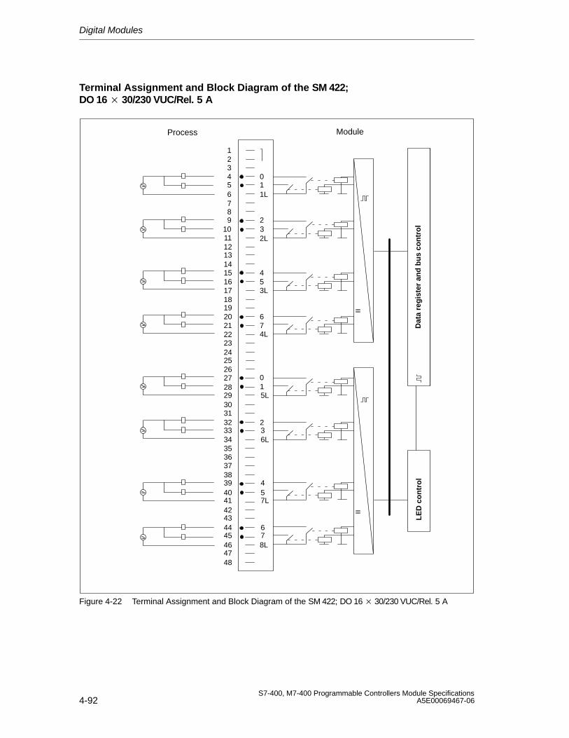
Digital Modules
4-92S7-400, M7-400 Programmable Controllers Module Specifications
A5E00069467-06
Terminal Assignment and Block Diagram of the SM 422; DO 16 30/230 VUC/Rel. 5 A
Dat
a re
gis
ter
and
bu
s co
ntr
ol
LE
D c
on
tro
l
123456789
101112131415161718192021222324252627282930313233343536373839404142434445464748
1L
2L
3L
5L
4L
6L
7L
8L
10
23
67
01
32
54
76
45
Process Module
Figure 4-22 Terminal Assignment and Block Diagram of the SM 422; DO 16 30/230 VUC/Rel. 5 A
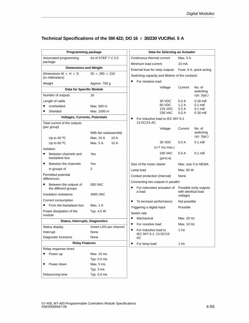
Digital Modules
4-93S7-400, M7-400 Programmable Controllers Module SpecificationsA5E00069467-06
Technical Specifications of the SM 422; DO 16 30/230 VUC/Rel. 5 A
Programming package
Associated programmingpackage
As of STEP 7 V 2.0
Dimensions and Weight
Dimensions W H D(in millimeters)
25 290 210
Weight Approx. 700 g
Data for Specific Module
Number of outputs 16
Length of cable
• Unshielded
• Shielded
Max. 600 m
Max. 1000 m
Voltages, Currents, Potentials
Total current of the outputs(per group)
Up to 40 oC
Up to 60 oC
With fan subassembly
Max. 10 A 10 A
Max. 5 A 10 A
Isolation
• Between channels andbackplane bus
Yes
• Between the channels
In groups of
Yes
2
Permitted potentialdifferences:
• Between the outputs ofthe different groups
500 VAC
Insulation resistance 4000 VAC
Current consumption
• From the backplane bus Max. 1 A
Power dissipation of themodule
Typ. 4.5 W
Status, Interrupts, Diagnostics
Status display
Interrupt
Diagnostic functions
Green LED per channel
None
None
Relay Features
Relay response times
• Power up
• Power down
Debouncing time
Max. 10 ms
Typ. 5.5 ms
Max. 5 ms
Typ. 3 ms
Typ. 0.5 ms
Data for Selecting an Actuator
Continuous thermal current Max. 5 A
Minimum load current 10 mA
External fuse for relay outputs Fuse, 6 A, quick-acting
Switching capacity and lifetime of the contacts
• For resistive load
Voltage Current No. ofswitchingcyc. (typ.)
30 VDC60 VDC125 VDC230 VAC
5.0 A1.2 A0.2 A5.0 A
0.18 mill0.1 mill0.1 mill0.18 mill
• For inductive load to IEC 947-5-113 DC/15 AC
Voltage Current No. ofswitchingcyc. (typ.)
30 VDC
(=7 ms max.)
5.0 A 0.1 mill
230 VAC
(pf=0.4)
5.0 A 0.1 mill
Size of the motor starter Max. size 5 to NEMA
Lamp load Max. 60 W
Contact protection (internal) None
Connecting two outputs in parallel
• For redundant actuation ofa load
Possible (only outputswith identical loadvoltage)
• To increase performance Not possible
Triggering a digital input Possible
Switch rate
• Mechanical Max. 20 Hz
• For resistive load Max. 10 Hz
• For inductive load to IEC 947-5-1, 13 DC/15AC
1 Hz
• For lamp load 1 Hz
Digital Modules
4-94S7-400, M7-400 Programmable Controllers Module Specifications
A5E00069467-06
Note
Use a suppressor circuit in environments with high humidity and where sparksmight occur at the relay contacts. This will increase the life of the relay contacts.
To do this, connect an RC element or a varistor parallel to the relay contacts or tothe load. The dimensions depend on the size of the load (see Chapter 4 of theinstallation manual).
5-1S7-400, M7-400 Programmable Controllers Module SpecificationsA5E00069467-06
Analog Modules
Structure of the Chapter
The present chapter is broken down into the following subjects:
1. Overview containing the modules that are available here and a description
2. Information that is generally available – in other words, affects all analogmodules (such as parameter assignment and diagnostics)
3. Information that refers to specific modules (for example, characteristics,diagram of connections and block diagram, technical specifications and specialcharacteristics of the module):
a) For analog input modules
b) For analog output modules
STEP 7 Blocks for Analog Functions
You can use blocks FC 100 to FC 111 to read and output analog values in STEP 7.You will find the FCs in the standard library of STEP 7 in the subdirectory called“S5-S7 Converting Blocks” (for a description refer to the STEP 7 online help systemfor the FCs).
Additional Information
Appendix A describes the structure of the parameter records (data records 0 and 1)in the system data. You must be familiar with this structure if you want to modify theparameters of the modules in the STEP 7 user program.
Appendix B describes the structure of the diagnostic data (data records 0, 1) in thesystem data. You must be familiar with this structure if you want to evaluate thediagnostic data of the modules in the STEP 7 user program.
5
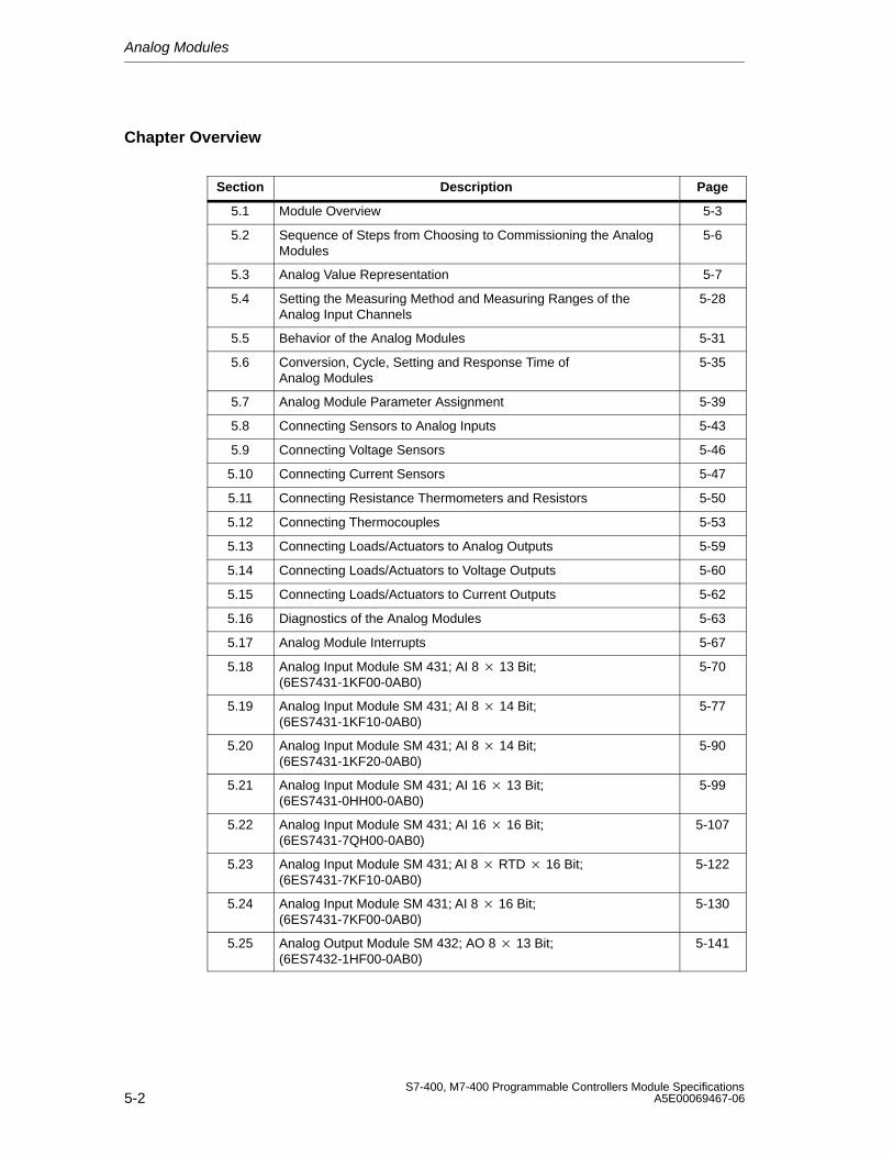
Analog Modules
5-2S7-400, M7-400 Programmable Controllers Module Specifications
A5E00069467-06
Chapter Overview
Section Description Page
5.1 Module Overview 5-3
5.2 Sequence of Steps from Choosing to Commissioning the AnalogModules
5-6
5.3 Analog Value Representation 5-7
5.4 Setting the Measuring Method and Measuring Ranges of theAnalog Input Channels
5-28
5.5 Behavior of the Analog Modules 5-31
5.6 Conversion, Cycle, Setting and Response Time of Analog Modules
5-35
5.7 Analog Module Parameter Assignment 5-39
5.8 Connecting Sensors to Analog Inputs 5-43
5.9 Connecting Voltage Sensors 5-46
5.10 Connecting Current Sensors 5-47
5.11 Connecting Resistance Thermometers and Resistors 5-50
5.12 Connecting Thermocouples 5-53
5.13 Connecting Loads/Actuators to Analog Outputs 5-59
5.14 Connecting Loads/Actuators to Voltage Outputs 5-60
5.15 Connecting Loads/Actuators to Current Outputs 5-62
5.16 Diagnostics of the Analog Modules 5-63
5.17 Analog Module Interrupts 5-67
5.18 Analog Input Module SM 431; AI 8 13 Bit;(6ES7431-1KF00-0AB0)
5-70
5.19 Analog Input Module SM 431; AI 8 14 Bit;(6ES7431-1KF10-0AB0)
5-77
5.20 Analog Input Module SM 431; AI 8 14 Bit;(6ES7431-1KF20-0AB0)
5-90
5.21 Analog Input Module SM 431; AI 16 13 Bit;(6ES7431-0HH00-0AB0)
5-99
5.22 Analog Input Module SM 431; AI 16 16 Bit;(6ES7431-7QH00-0AB0)
5-107
5.23 Analog Input Module SM 431; AI 8 RTD 16 Bit;(6ES7431-7KF10-0AB0)
5-122
5.24 Analog Input Module SM 431; AI 8 16 Bit;(6ES7431-7KF00-0AB0)
5-130
5.25 Analog Output Module SM 432; AO 8 13 Bit;(6ES7432-1HF00-0AB0)
5-141
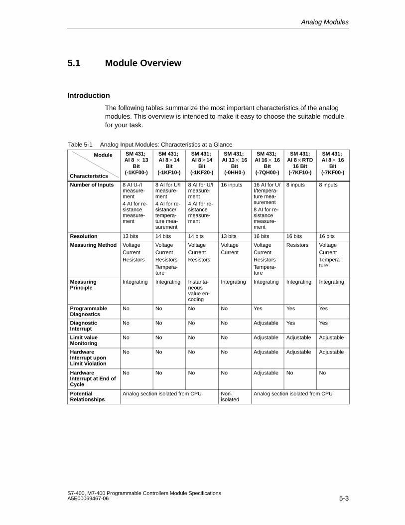
Analog Modules
5-3S7-400, M7-400 Programmable Controllers Module SpecificationsA5E00069467-06
5.1 Module Overview
Introduction
The following tables summarize the most important characteristics of the analogmodules. This overview is intended to make it easy to choose the suitable modulefor your task.
Table 5-1 Analog Input Modules: Characteristics at a Glance
Module
Characteristics
SM 431; AI 8 13
Bit(-1KF00-)
SM 431; AI 814
Bit(-1KF10-)
SM 431; AI 814
Bit(-1KF20-)
SM 431; AI 13 16
Bit(-0HH0-)
SM 431; AI 16 16
Bit(-7QH00-)
SM 431;AI 8RTD
16 Bit(-7KF10-)
SM 431; AI 8 16
Bit(-7KF00-)
Number of Inputs 8 AI U-/Imeasure-ment4 AI for re-sistancemeasure-ment
8 AI for U/Imeasure-ment4 AI for re-sistance/tempera-ture mea-surement
8 AI for U/Imeasure-ment4 AI for re-sistancemeasure-ment
16 inputs 16 AI for U/I/tempera-ture mea-surement8 AI for re-sistancemeasure-ment
8 inputs 8 inputs
Resolution 13 bits 14 bits 14 bits 13 bits 16 bits 16 bits 16 bits
Measuring Method VoltageCurrentResistors
VoltageCurrentResistorsTempera-ture
VoltageCurrentResistors
VoltageCurrent
VoltageCurrentResistorsTempera-ture
Resistors VoltageCurrentTempera-ture
MeasuringPrinciple
Integrating Integrating Instanta-neousvalue en-coding
Integrating Integrating Integrating Integrating
ProgrammableDiagnostics
No No No No Yes Yes Yes
DiagnosticInterrupt
No No No No Adjustable Yes Yes
Limit valueMonitoring
No No No No Adjustable Adjustable Adjustable
HardwareInterrupt uponLimit Violation
No No No No Adjustable Adjustable Adjustable
HardwareInterrupt at End ofCycle
No No No No Adjustable No No
PotentialRelationships
Analog section isolated from CPU Non-isolated
Analog section isolated from CPU
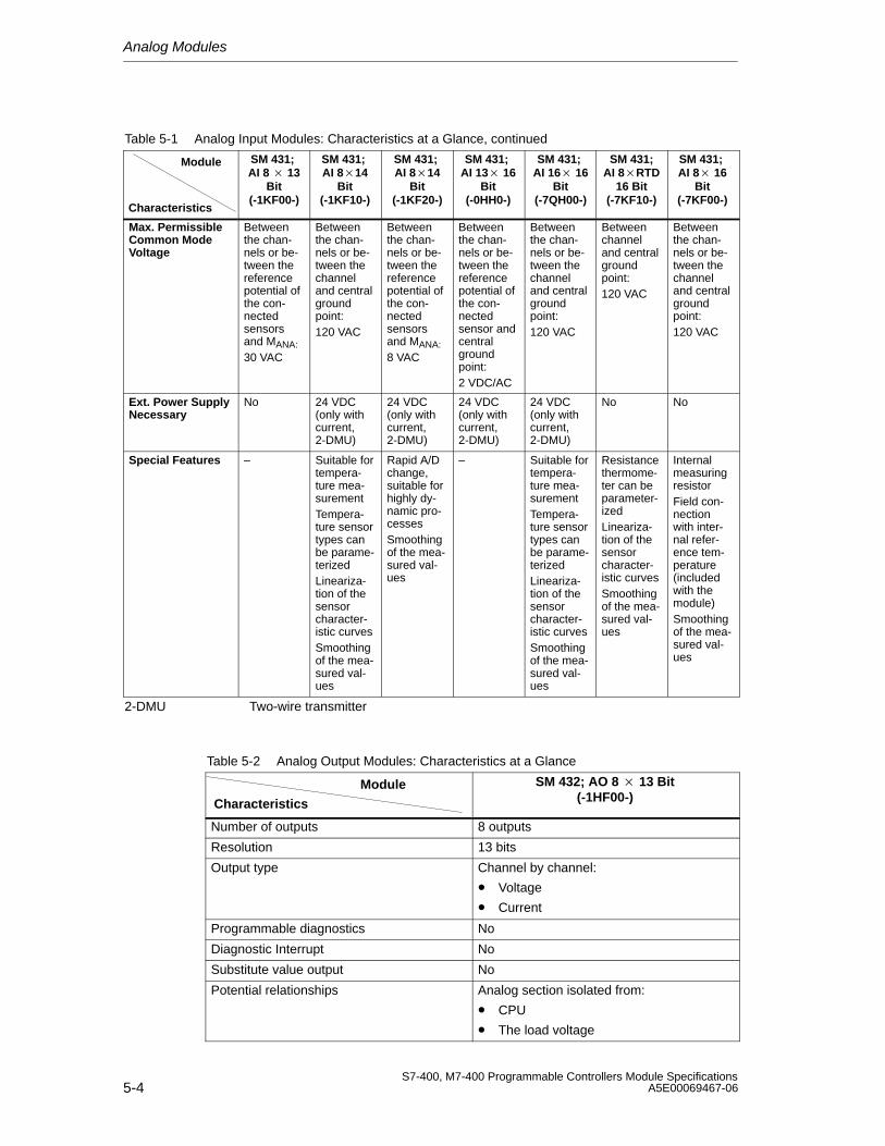
Analog Modules
5-4S7-400, M7-400 Programmable Controllers Module Specifications
A5E00069467-06
Table 5-1 Analog Input Modules: Characteristics at a Glance, continued
Module SM 431; AI 8 16
Bit(-7KF00-)
SM 431;AI 8RTD
16 Bit(-7KF10-)
SM 431; AI 16 16
Bit(-7QH00-)
SM 431; AI 13 16
Bit(-0HH0-)
SM 431; AI 814
Bit(-1KF20-)
SM 431; AI 814
Bit(-1KF10-)
SM 431; AI 8 13
Bit(-1KF00-)
Characteristics
Max. PermissibleCommon ModeVoltage
Betweenthe chan-nels or be-tween thereferencepotential ofthe con-nectedsensorsand MANA:30 VAC
Betweenthe chan-nels or be-tween thechanneland centralgroundpoint:120 VAC
Betweenthe chan-nels or be-tween thereferencepotential ofthe con-nectedsensorsand MANA:8 VAC
Betweenthe chan-nels or be-tween thereferencepotential ofthe con-nectedsensor andcentralgroundpoint:2 VDC/AC
Betweenthe chan-nels or be-tween thechanneland centralgroundpoint:120 VAC
Betweenchanneland centralgroundpoint:120 VAC
Betweenthe chan-nels or be-tween thechanneland centralgroundpoint:120 VAC
Ext. Power SupplyNecessary
No 24 VDC(only withcurrent,2-DMU)
24 VDC(only withcurrent,2-DMU)
24 VDC(only withcurrent,2-DMU)
24 VDC(only withcurrent,2-DMU)
No No
Special Features – Suitable fortempera-ture mea-surementTempera-ture sensortypes canbe parame-terizedLineariza-tion of thesensorcharacter-istic curvesSmoothingof the mea-sured val-ues
Rapid A/Dchange,suitable forhighly dy-namic pro-cessesSmoothingof the mea-sured val-ues
– Suitable fortempera-ture mea-surementTempera-ture sensortypes canbe parame-terizedLineariza-tion of thesensorcharacter-istic curvesSmoothingof the mea-sured val-ues
Resistancethermome-ter can beparameter-izedLineariza-tion of thesensorcharacter-istic curvesSmoothingof the mea-sured val-ues
InternalmeasuringresistorField con-nectionwith inter-nal refer-ence tem-perature(includedwith themodule)Smoothingof the mea-sured val-ues
2-DMU Two-wire transmitter
Table 5-2 Analog Output Modules: Characteristics at a Glance
Module
Characteristics
SM 432; AO 8 13 Bit(-1HF00-)
Number of outputs 8 outputs
Resolution 13 bits
Output type Channel by channel:
• Voltage
• Current
Programmable diagnostics No
Diagnostic Interrupt No
Substitute value output No
Potential relationships Analog section isolated from:
• CPU
• The load voltage
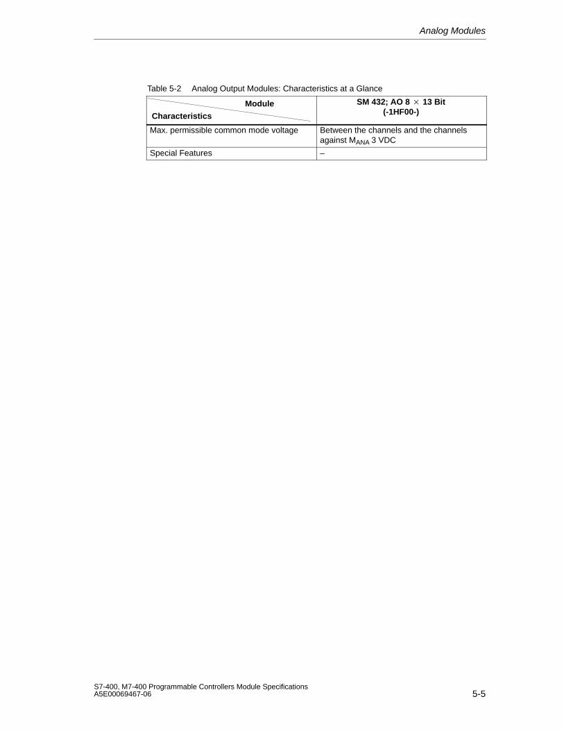
Analog Modules
5-5S7-400, M7-400 Programmable Controllers Module SpecificationsA5E00069467-06
Table 5-2 Analog Output Modules: Characteristics at a Glance
Module SM 432; AO 8 13 Bit(-1HF00-)Characteristics
Max. permissible common mode voltage Between the channels and the channelsagainst MANA 3 VDC
Special Features –
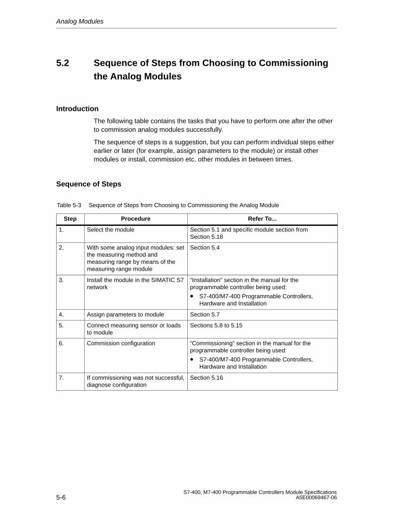
Analog Modules
5-6S7-400, M7-400 Programmable Controllers Module Specifications
A5E00069467-06
5.2 Sequence of Steps from Choosing to Commissioningthe Analog Modules
Introduction
The following table contains the tasks that you have to perform one after the otherto commission analog modules successfully.
The sequence of steps is a suggestion, but you can perform individual steps eitherearlier or later (for example, assign parameters to the module) or install othermodules or install, commission etc. other modules in between times.
Sequence of Steps
Table 5-3 Sequence of Steps from Choosing to Commissioning the Analog Module
Step Procedure Refer To...
1. Select the module Section 5.1 and specific module section fromSection 5.18
2. With some analog input modules: setthe measuring method andmeasuring range by means of themeasuring range module
Section 5.4
3. Install the module in the SIMATIC S7network
“Installation” section in the manual for theprogrammable controller being used:
• S7-400/M7-400 Programmable Controllers,Hardware and Installation
4. Assign parameters to module Section 5.7
5. Connect measuring sensor or loadsto module
Sections 5.8 to 5.15
6. Commission configuration “Commissioning” section in the manual for theprogrammable controller being used:
• S7-400/M7-400 Programmable Controllers,Hardware and Installation
7. If commissioning was not successful,diagnose configuration
Section 5.16
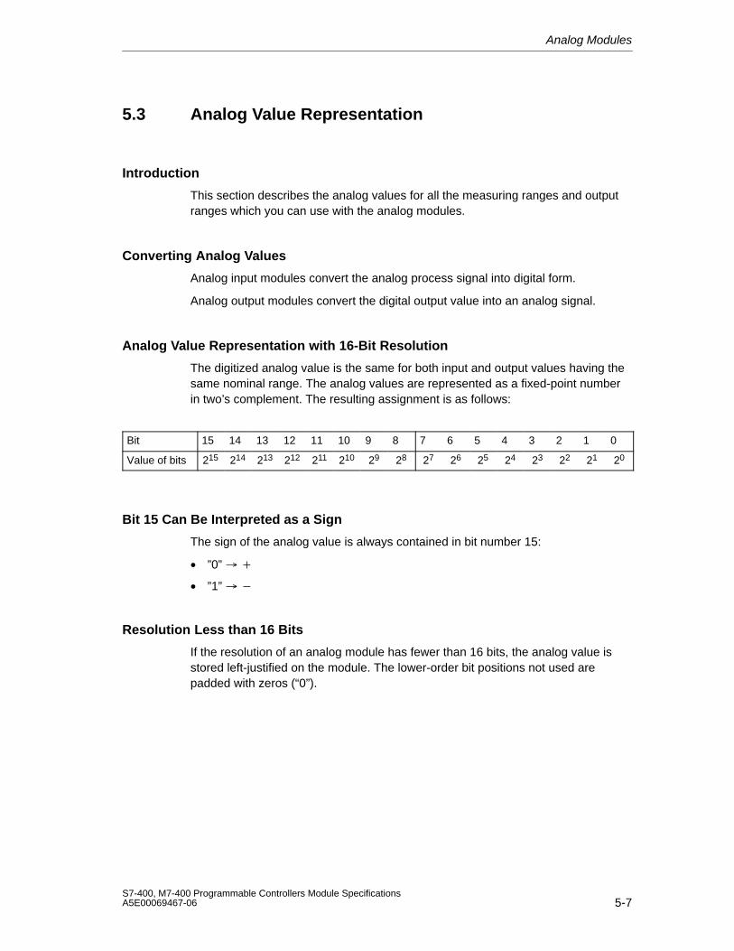
Analog Modules
5-7S7-400, M7-400 Programmable Controllers Module SpecificationsA5E00069467-06
5.3 Analog Value Representation
Introduction
This section describes the analog values for all the measuring ranges and outputranges which you can use with the analog modules.
Converting Analog Values
Analog input modules convert the analog process signal into digital form.
Analog output modules convert the digital output value into an analog signal.
Analog Value Representation with 16-Bit Resolution
The digitized analog value is the same for both input and output values having thesame nominal range. The analog values are represented as a fixed-point numberin two’s complement. The resulting assignment is as follows:
Bit 15 14 13 12 11 10 9 8 7 6 5 4 3 2 1 0
Value of bits 215 214 213 212 211 210 29 28 27 26 25 24 23 22 21 20
Bit 15 Can Be Interpreted as a Sign
The sign of the analog value is always contained in bit number 15:
• ”0”
• ”1”
Resolution Less than 16 Bits
If the resolution of an analog module has fewer than 16 bits, the analog value isstored left-justified on the module. The lower-order bit positions not used arepadded with zeros (“0”).
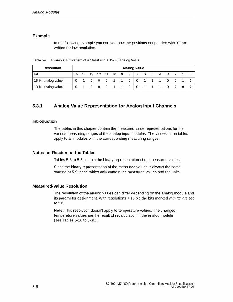
Analog Modules
5-8S7-400, M7-400 Programmable Controllers Module Specifications
A5E00069467-06
Example
In the following example you can see how the positions not padded with “0” arewritten for low resolution.
Table 5-4 Example: Bit Pattern of a 16-Bit and a 13-Bit Analog Value
Resolution Analog Value
Bit 15 14 13 12 11 10 9 8 7 6 5 4 3 2 1 0
16-bit analog value 0 1 0 0 0 1 1 0 0 1 1 1 0 0 1 1
13-bit analog value 0 1 0 0 0 1 1 0 0 1 1 1 0 0 0 0
5.3.1 Analog Value Representation for Analog Input Channels
Introduction
The tables in this chapter contain the measured value representations for thevarious measuring ranges of the analog input modules. The values in the tablesapply to all modules with the corresponding measuring ranges.
Notes for Readers of the Tables
Tables 5-6 to 5-8 contain the binary representation of the measured values.
Since the binary representation of the measured values is always the same,starting at 5-9 these tables only contain the measured values and the units.
Measured-Value Resolution
The resolution of the analog values can differ depending on the analog module andits parameter assignment. With resolutions < 16 bit, the bits marked with “x” are setto “0”.
Note: This resolution doesn’t apply to temperature values. The changedtemperature values are the result of recalculation in the analog module (see Tables 5-16 to 5-30).
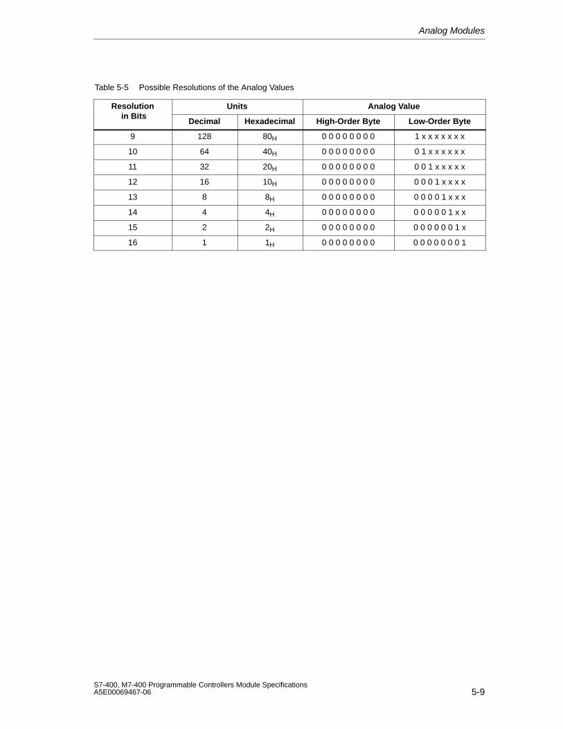
Analog Modules
5-9S7-400, M7-400 Programmable Controllers Module SpecificationsA5E00069467-06
Table 5-5 Possible Resolutions of the Analog Values
Resolution Units Analog Value in Bits
Decimal Hexadecimal High-Order Byte Low-Order Byte
9 128 80H 0 0 0 0 0 0 0 0 1 x x x x x x x
10 64 40H 0 0 0 0 0 0 0 0 0 1 x x x x x x
11 32 20H 0 0 0 0 0 0 0 0 0 0 1 x x x x x
12 16 10H 0 0 0 0 0 0 0 0 0 0 0 1 x x x x
13 8 8H 0 0 0 0 0 0 0 0 0 0 0 0 1 x x x
14 4 4H 0 0 0 0 0 0 0 0 0 0 0 0 0 1 x x
15 2 2H 0 0 0 0 0 0 0 0 0 0 0 0 0 0 1 x
16 1 1H 0 0 0 0 0 0 0 0 0 0 0 0 0 0 0 1
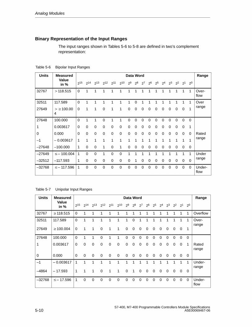
Analog Modules
5-10S7-400, M7-400 Programmable Controllers Module Specifications
A5E00069467-06
Binary Representation of the Input Ranges
The input ranges shown in Tables 5-6 to 5-8 are defined in two’s complementrepresentation:
Table 5-6 Bipolar Input Ranges
Units Measured Data Word RangeValue in % 215 214 213 212 211 210 29 28 27 26 25 24 23 22 21 20
32767 118.515 0 1 1 1 1 1 1 1 1 1 1 1 1 1 1 1 Over-flow
32511 117.589 0 1 1 1 1 1 1 0 1 1 1 1 1 1 1 1 Over
27649 100.004
0 1 1 0 1 1 0 0 0 0 0 0 0 0 0 1range
27648 100.000 0 1 1 0 1 1 0 0 0 0 0 0 0 0 0 0
1 0.003617 0 0 0 0 0 0 0 0 0 0 0 0 0 0 0 1
0 0.000 0 0 0 0 0 0 0 0 0 0 0 0 0 0 0 0 Rated
–1 – 0.003617 1 1 1 1 1 1 1 1 1 1 1 1 1 1 1 1range
–27648 –100.000 1 0 0 1 0 1 0 0 0 0 0 0 0 0 0 0
–27649 – 100.004 1 0 0 1 0 0 1 1 1 1 1 1 1 1 1 1 Under
–32512 –117.593 1 0 0 0 0 0 0 1 0 0 0 0 0 0 0 0range
–32768 – 117.596 1 0 0 0 0 0 0 0 0 0 0 0 0 0 0 0 Under-flow
Table 5-7 Unipolar Input Ranges
Units Measured Data Word RangeValue in % 215 214 213 212 211 210 29 28 27 26 25 24 23 22 21 20
32767 118.515 0 1 1 1 1 1 1 1 1 1 1 1 1 1 1 1 Overflow
32511 117.589 0 1 1 1 1 1 1 0 1 1 1 1 1 1 1 1 Over-
27649 100.004 0 1 1 0 1 1 0 0 0 0 0 0 0 0 0 1range
27648 100.000 0 1 1 0 1 1 0 0 0 0 0 0 0 0 0 0
1 0.003617 0 0 0 0 0 0 0 0 0 0 0 0 0 0 0 1 Ratedrange
0 0.000 0 0 0 0 0 0 0 0 0 0 0 0 0 0 0 0
–1 – 0.003617 1 1 1 1 1 1 1 1 1 1 1 1 1 1 1 1 Under-
–4864 – 17.593 1 1 1 0 1 1 0 1 0 0 0 0 0 0 0 0range
–32768 – 17.596 1 0 0 0 0 0 0 0 0 0 0 0 0 0 0 0 Under-flow
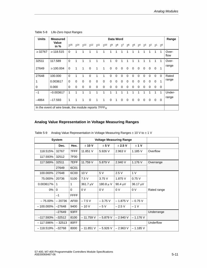
Analog Modules
5-11S7-400, M7-400 Programmable Controllers Module SpecificationsA5E00069467-06
Table 5-8 Life-Zero Input Ranges
Units Measured Data Word RangeValue in % 215 214 213 212 211 210 29 28 27 26 25 24 23 22 21 20
32767 118.515 0 1 1 1 1 1 1 1 1 1 1 1 1 1 1 1 Over-flow
32511 117.589 0 1 1 1 1 1 1 0 1 1 1 1 1 1 1 1 Over-
27649 100.004 0 1 1 0 1 1 0 0 0 0 0 0 0 0 0 1range
27648 100.000 0 1 1 0 1 1 0 0 0 0 0 0 0 0 0 0 Rated
1 0.003617 0 0 0 0 0 0 0 0 0 0 0 0 0 0 0 1range
0 0.000 0 0 0 0 0 0 0 0 0 0 0 0 0 0 0 0
–1 –0.003617 1 1 1 1 1 1 1 1 1 1 1 1 1 1 1 1 Under-
–4864 –17.593 1 1 1 0 1 1 0 1 0 0 0 0 0 0 0 0range
In the event of wire break, the module reports 7FFFH
Analog Value Representation in Voltage Measuring Ranges
Table 5-9 Analog Value Representation in Voltage Measuring Ranges ± 10 V to ± 1 V
System Voltage Measuring Range
Dec. Hex. ± 10 V ± 5 V ± 2.5 V ± 1 V
118.515% 32767 7FFF 11.851 V 5.926 V 2.963 V 1.185 V Overflow
117.593% 32512 7F00
117.589% 32511 7EFF 11.759 V 5.879 V 2.940 V 1.176 V Overrange
27649 6C01
100.000% 27648 6C00 10 V 5 V 2.5 V 1 V
75.000% 20736 5100 7.5 V 3.75 V 1.875 V 0.75 V
0.003617% 1 1 361.7 V 180.8 V 90.4 V 36.17 V
0% 0 0 0 V 0 V 0 V 0 V Rated range
–1 FFFF
– 75.00% – 20736 AF00 – 7.5 V – 3.75 V – 1.875 V – 0.75 V
– 100.000% –27648 9400 – 10 V – 5 V – 2.5 V – 1 V
–27649 93FF Underrange
–117.593% –32512 8100 – 11.759 V – 5.879 V – 2.940 V – 1.176 V
– 117.596% – 32513 80FF Underflow
– 118.519% –32768 8000 – 11.851 V – 5.926 V – 2.963 V – 1.185 V
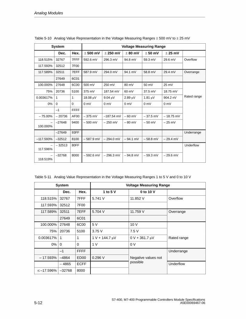
Analog Modules
5-12S7-400, M7-400 Programmable Controllers Module Specifications
A5E00069467-06
Table 5-10 Analog Value Representation in the Voltage Measuring Ranges ± 500 mV to ± 25 mV
System Voltage Measuring Range
Dec. Hex. ± 500 mV ± 250 mV ± 80 mV ± 50 mV ± 25 mV
118.515% 32767 7FFF 592.6 mV 296.3 mV 94.8 mV 59.3 mV 29.6 mV Overflow
117.593% 32512 7F00
117.589% 32511 7EFF 587.9 mV 294.0 mV 94.1 mV 58.8 mV 29.4 mV Overrange
27649 6C01
100.000% 27648 6C00 500 mV 250 mV 80 mV 50 mV 25 mV
75% 20736 5100 375 mV 187.54 mV 60 mV 37.5 mV 18.75 mV
0.003617% 1 1 18.08 V 9.04 V 2.89 V 1.81 V 904.2 nV Rated range
0% 0 0 0 mV 0 mV 0 mV 0 mV 0 mV
–1 FFFF
– 75.00% – 20736 AF00 – 375 mV –187.54 mV – 60 mV – 37.5 mV – 18.75 mV
–100.000%
–27648 9400 – 500 mV – 250 mV – 80 mV – 50 mV – 25 mV
–27649 93FF Underrange
–117.593% –32512 8100 – 587.9 mV – 294.0 mV – 94.1 mV – 58.8 mV – 29.4 mV
–117.596%
– 32513 80FF Underflow
–118.519%
–32768 8000 – 592.6 mV – 296.3 mV – 94.8 mV – 59.3 mV – 29.6 mV
Table 5-11 Analog Value Representation in the Voltage Measuring Ranges 1 to 5 V and 0 to 10 V
System Voltage Measuring Range
Dec. Hex. 1 to 5 V 0 to 10 V
118.515% 32767 7FFF 5.741 V 11.852 V Overflow
117.593% 32512 7F00
117.589% 32511 7EFF 5.704 V 11.759 V Overrange
27649 6C01
100.000% 27648 6C00 5 V 10 V
75% 20736 5100 3.75 V 7.5 V
0.003617% 1 1 1 V + 144.7 V 0 V + 361.7 V Rated range
0% 0 0 1 V 0 V
–1 FFFF Underrange
– 17.593% –4864 ED00 0.296 V Negative values not
– 4865 ECFF possible Underflow
–17.596% –32768 8000
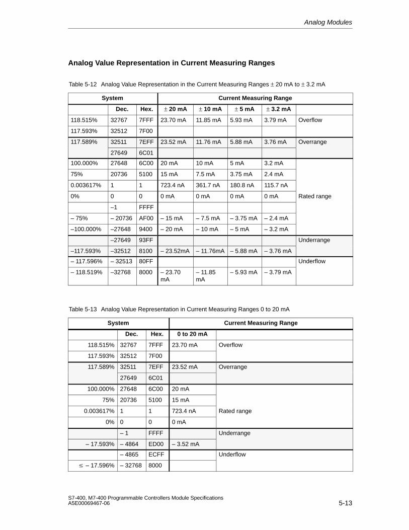
Analog Modules
5-13S7-400, M7-400 Programmable Controllers Module SpecificationsA5E00069467-06
Analog Value Representation in Current Measuring Ranges
Table 5-12 Analog Value Representation in the Current Measuring Ranges ± 20 mA to ± 3.2 mA
System Current Measuring Range
Dec. Hex. ± 20 mA ± 10 mA ± 5 mA ± 3.2 mA
118.515% 32767 7FFF 23.70 mA 11.85 mA 5.93 mA 3.79 mA Overflow
117.593% 32512 7F00
117.589% 32511 7EFF 23.52 mA 11.76 mA 5.88 mA 3.76 mA Overrange
27649 6C01
100.000% 27648 6C00 20 mA 10 mA 5 mA 3.2 mA
75% 20736 5100 15 mA 7.5 mA 3.75 mA 2.4 mA
0.003617% 1 1 723.4 nA 361.7 nA 180.8 nA 115.7 nA
0% 0 0 0 mA 0 mA 0 mA 0 mA Rated range
–1 FFFF
– 75% – 20736 AF00 – 15 mA – 7.5 mA – 3.75 mA – 2.4 mA
–100.000% –27648 9400 – 20 mA – 10 mA – 5 mA – 3.2 mA
–27649 93FF Underrange
–117.593% –32512 8100 – 23.52mA – 11.76mA – 5.88 mA – 3.76 mA
– 117.596% – 32513 80FF Underflow
– 118.519% –32768 8000 – 23.70mA
– 11.85mA
– 5.93 mA – 3.79 mA
Table 5-13 Analog Value Representation in Current Measuring Ranges 0 to 20 mA
System Current Measuring Range
Dec. Hex. 0 to 20 mA
118.515% 32767 7FFF 23.70 mA Overflow
117.593% 32512 7F00
117.589% 32511 7EFF 23.52 mA Overrange
27649 6C01
100.000% 27648 6C00 20 mA
75% 20736 5100 15 mA
0.003617% 1 1 723.4 nA Rated range
0% 0 0 0 mA
– 1 FFFF Underrange
– 17.593% – 4864 ED00 – 3.52 mA
– 4865 ECFF Underflow
– 17.596% – 32768 8000

Analog Modules
5-14S7-400, M7-400 Programmable Controllers Module Specifications
A5E00069467-06
Table 5-14 Analog Value Representation in Current Measuring Ranges 4 to 20 mA
System Current Measuring Range
Dec. Hex. 4 to 20 mA
118.515% 32767 7FFF 22.96 mA Overflow
117.593% 32512 7F00
117.589% 32511 7EFF 22.81 mA Overrange
27649 6C01
100.000% 27648 6C00 20 mA
75% 20736 5100 16 mA
0.003617% 1 1 4 mA +578.7 nA
Rated range
0% 0 0 4 mA
– 1 FFFF Underrange
– 17.593% – 4864 ED00 1.185 mA
Underflow
– 17.596% – 32767 7FFF
Analog Value Representation for Resistance-Type Sensors
Table 5-15 Analog Value Representation for Resistance-Type Sensors from 48 to 6 k
System Resistance-Type Sensor Range
Dec. Hex. 48 150 300 600 6 k
118.515% 32767 7FFF 56.89 177.77
355.54 711.09 7.11 k Overflow
117.593% 32512 7F00
117.589% 32511 7EFF 56.44 176.38
352.77 705.53 7.06 k Overrange
27649 6C01
100.000% 27648 6C00 48 150 300 600 6 k
75% 20736 5100 36 112.5 225 450 4.5 k Rated
0.003617% 1 1 1.74m 5.43m 10.85m 21.70m 217.0mrange
0% 0 0 0 0 0 0 0
(negative values physically not possible) Underrange
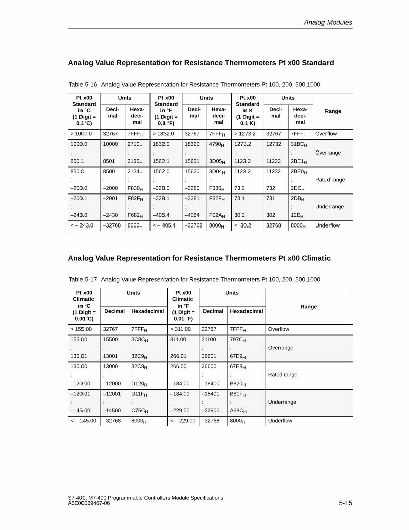
Analog Modules
5-15S7-400, M7-400 Programmable Controllers Module SpecificationsA5E00069467-06
Analog Value Representation for Resistance Thermometers Pt x00 Standard
Table 5-16 Analog Value Representation for Resistance Thermometers Pt 100, 200, 500,1000
Pt x00 Units Pt x00 Units Pt x00 UnitsStandard
in C(1 Digit =
0.1C)
Deci-mal
Hexa-deci-mal
Standardin F
(1 Digit =0.1 F)
Deci-mal
Hexa-deci-mal
Standardin K
(1 Digit =0.1 K)
Deci-mal
Hexa-deci-mal
Range
> 1000.0 32767 7FFFH > 1832.0 32767 7FFFH > 1273.2 32767 7FFFH Overflow
1000.0
:
850.1
10000
:
8501
2710H
:
2135H
1832.0
:
1562.1
18320
:
15621
4790H
:
3D05H
1273.2
:
1123.3
12732
:
11233
31BCH
:
2BE1H
Overrange
850.0
:
–200.0
8500
:
–2000
2134H
:
F830H
1562.0
:
–328.0
15620
:
–3280
3D04H
:
F330H
1123.2
:
73.2
11232
:
732
2BE0H
:
2DCH
Rated range
–200.1
:
–243.0
–2001
:
–2430
F82FH
:
F682H
–328.1
:
–405.4
–3281
:
–4054
F32FH
:
F02AH
73.1
:
30.2
731
:
302
2DBH
:
12EH
Underrange
< – 243.0 –32768 8000H < – 405.4 –32768 8000H < 30.2 32768 8000H Underflow
Analog Value Representation for Resistance Thermometers Pt x00 Climatic
Table 5-17 Analog Value Representation for Resistance Thermometers Pt 100, 200, 500,1000
Pt x00Climatic
Units Pt x00Climatic
Units
in C(1 Digit =0.01C)
Decimal Hexadecimalin F
(1 Digit =0.01F)
Decimal HexadecimalRange
> 155.00 32767 7FFFH > 311.00 32767 7FFFH Overflow
155.00
:
130.01
15500
:
13001
3C8CH
:
32C9H
311.00
:
266.01
31100
:
26601
797CH
:
67E9H
Overrange
130.00
:
–120.00
13000
:
–12000
32C8H
:
D120H
266.00
:
–184.00
26600
:
–18400
67E8H
:
B820H
Rated range
–120.01
:
–145.00
–12001
:
–14500
D11FH
:
C75CH
–184.01
:
–229.00
–18401
:
–22900
B81FH
:
A68CH
Underrange
< – 145.00 –32768 8000H < – 229.00 –32768 8000H Underflow
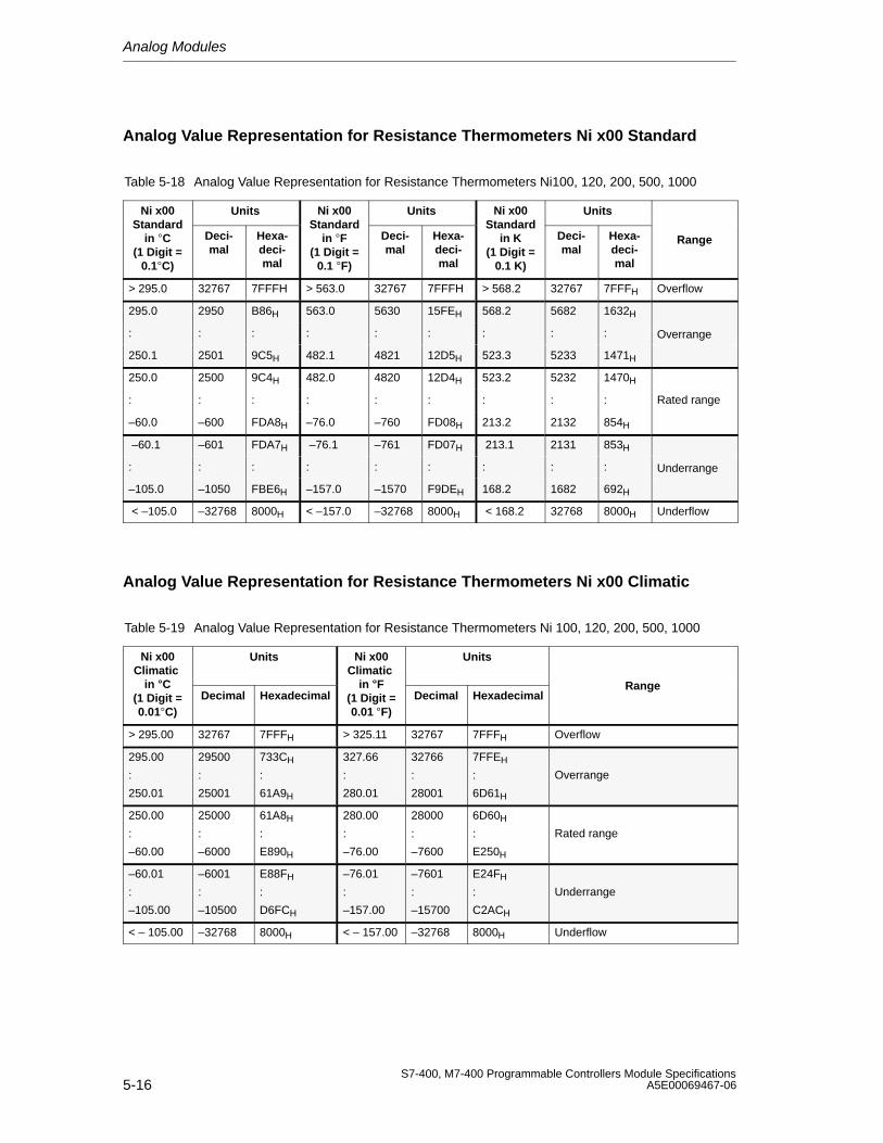
Analog Modules
5-16S7-400, M7-400 Programmable Controllers Module Specifications
A5E00069467-06
Analog Value Representation for Resistance Thermometers Ni x00 Standard
Table 5-18 Analog Value Representation for Resistance Thermometers Ni100, 120, 200, 500, 1000
Ni x00 Units Ni x00 Units Ni x00 UnitsStandard
in C(1 Digit =
0.1C)
Deci-mal
Hexa-deci-mal
Standardin F
(1 Digit =0.1 F)
Deci-mal
Hexa-deci-mal
Standardin K
(1 Digit =0.1 K)
Deci-mal
Hexa-deci-mal
Range
> 295.0 32767 7FFFH > 563.0 32767 7FFFH > 568.2 32767 7FFFH Overflow
295.0 2950 B86H 563.0 5630 15FEH 568.2 5682 1632H
: : : : : : : : : Overrange
250.1 2501 9C5H 482.1 4821 12D5H 523.3 5233 1471H
250.0 2500 9C4H 482.0 4820 12D4H 523.2 5232 1470H
: : : : : : : : : Rated range
–60.0 –600 FDA8H –76.0 –760 FD08H 213.2 2132 854H
–60.1 –601 FDA7H –76.1 –761 FD07H 213.1 2131 853H
: : : : : : : : : Underrange
–105.0 –1050 FBE6H –157.0 –1570 F9DEH 168.2 1682 692H
< –105.0 –32768 8000H < –157.0 –32768 8000H < 168.2 32768 8000H Underflow
Analog Value Representation for Resistance Thermometers Ni x00 Climatic
Table 5-19 Analog Value Representation for Resistance Thermometers Ni 100, 120, 200, 500, 1000
Ni x00Climatic
Units Ni x00Climatic
Units
in C(1 Digit =0.01C)
Decimal Hexadecimalin F
(1 Digit =0.01F)
Decimal HexadecimalRange
> 295.00 32767 7FFFH > 325.11 32767 7FFFH Overflow
295.00
:
250.01
29500
:
25001
733CH
:
61A9H
327.66
:
280.01
32766
:
28001
7FFEH
:
6D61H
Overrange
250.00
:
–60.00
25000
:
–6000
61A8H
:
E890H
280.00
:
–76.00
28000
:
–7600
6D60H
:
E250H
Rated range
–60.01
:
–105.00
–6001
:
–10500
E88FH
:
D6FCH
–76.01
:
–157.00
–7601
:
–15700
E24FH
:
C2ACH
Underrange
< – 105.00 –32768 8000H < – 157.00 –32768 8000H Underflow
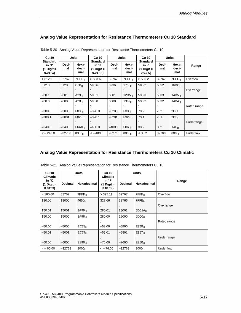
Analog Modules
5-17S7-400, M7-400 Programmable Controllers Module SpecificationsA5E00069467-06
Analog Value Representation for Resistance Thermometers Cu 10 Standard
Table 5-20 Analog Value Representation for Resistance Thermometers Cu 10
Cu 10 Units Cu 10 Units Cu 10 UnitsStandard
in C(1 Digit =0.01C)
Deci-mal
Hexa-deci-mal
Standardin F
(1 Digit =0.01 F)
Deci-mal
Hexa-deci-mal
Standardin K
(1 Digit =0.01 K)
Deci-mal
Hexa-deci-mal
Range
> 312.0 32767 7FFFH > 593.6 32767 7FFFH > 585.2 32767 7FFFH Overflow
312.0
:
260.1
3120
:
2601
C30H
:
A29H
593.6
:
500.1
5936
:
5001
1730H
:
12D5H
585.2
:
533.3
5852
:
5333
16DCH
:
14D5H
Overrange
260.0
:
–200.0
2600
:
–2000
A28H
:
F830H
500.0
:
–328.0
5000
:
–3280
1389H
:
F330H
533.2
:
73.2
5332
:
732
14D4H
:
2DCH
Rated range
–200.1
:
–240.0
–2001
:
–2400
F82FH
:
F6A0H
–328.1
:
–400.0
–3281
:
–4000
F32FH
:
F060H
73.1
:
33.2
731
:
332
2DBH
:
14CH
Underrange
< – 240.0 –32768 8000H < – 400.0 –32768 8000H < 33.2 32768 8000H Underflow
Analog Value Representation for Resistance Thermometers Cu 10 Climatic
Table 5-21 Analog Value Representation for Resistance Thermometers Cu 10
Cu 10Climatic
Units Cu 10Climatic
Units
in C(1 Digit =0.01C)
Decimal Hexadecimalin F
(1 Digit =0.01F)
Decimal HexadecimalRange
> 180.00 32767 7FFFH > 325.11 32767 7FFFH Overflow
180.00
:
150.01
18000
:
15001
4650H
:
3A99H
327.66
:
280.01
32766
:
28001
7FFEH
:
6D61AH
Overrange
150.00
:
–50.00
15000
:
–5000
3A98H
:
EC78H
280.00
:
–58.00
28000
:
–5800
6D60H
:
E958H
Rated range
–50.01
:
–60.00
–5001
:
–6000
EC77H
:
E890H
–58.01
:
–76.00
–5801
:
–7600
E957H
:
E250H
Underrange
< – 60.00 –32768 8000H < – 76.00 –32768 8000H Underflow
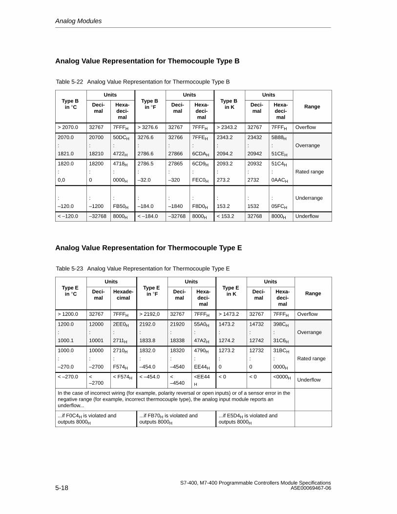
Analog Modules
5-18S7-400, M7-400 Programmable Controllers Module Specifications
A5E00069467-06
Analog Value Representation for Themocouple Type B
Table 5-22 Analog Value Representation for Thermocouple Type B
Units Units UnitsType B
in C Deci-mal
Hexa-deci-mal
Type B in F Deci-
malHexa-deci-mal
Type B in K Deci-
malHexa-deci-mal
Range
> 2070.0 32767 7FFFH > 3276.6 32767 7FFFH > 2343.2 32767 7FFFH Overflow
2070.0
:
1821.0
20700
:
18210
50DCH
:
4722H
3276.6
:
2786.6
32766
:
27866
7FFEH
:
6CDAH
2343.2
:
2094.2
23432
:
20942
5B88H
:
51CEH
Overrange
1820.0
:
0,0
18200
:
0
4718H
:
0000H
2786.5
:
–32.0
27865
:
–320
6CD9H
:
FEC0H
2093.2
:
273.2
20932
:
2732
51C4H
:
0AACH
Rated range
:
–120.0
:
–1200
:
FB50H
:
–184.0
:
–1840
:
F8D0H
:
153.2
:
1532
:
05FCH
Underrange
< –120.0 –32768 8000H < –184.0 –32768 8000H < 153.2 32768 8000H Underflow
Analog Value Representation for Thermocouple Type E
Table 5-23 Analog Value Representation for Thermocouple Type E
Units Units UnitsType E
in C Deci-mal
Hexade-cimal
Type E in F Deci-
malHexa-deci-mal
Type E in K Deci-
malHexa-deci-mal
Range
> 1200.0 32767 7FFFH > 2192,0 32767 7FFFH > 1473.2 32767 7FFFH Overflow
1200.0
:
1000.1
12000
:
10001
2EE0H
:
2711H
2192.0
:
1833.8
21920
:
18338
55A0H
:
47A2H
1473.2
:
1274.2
14732
:
12742
398CH
:
31C6H
Overrange
1000.0
:
–270.0
10000
:
–2700
2710H
:
F574H
1832.0
:
–454.0
18320
:
–4540
4790H
:
EE44H
1273.2
:
0
12732
:
0
31BCH
:
0000H
Rated range
< –270.0 <–2700
< F574H < –454.0 <–4540
<EE44H
< 0 < 0 <0000H Underflow
In the case of incorrect wiring (for example, polarity reversal or open inputs) or of a sensor error in thenegative range (for example, incorrect thermocouple type), the analog input module reports anunderflow...
...if F0C4H is violated andoutputs 8000H
...if FB70H is violated andoutputs 8000H
...if E5D4H is violated andoutputs 8000H
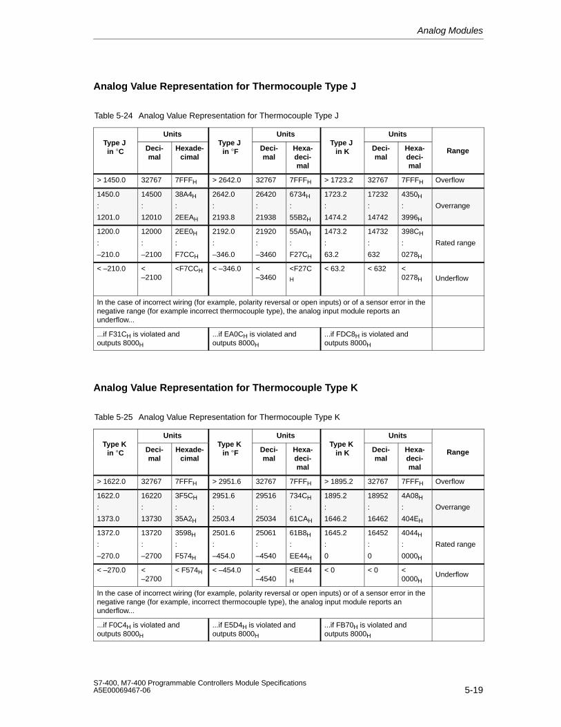
Analog Modules
5-19S7-400, M7-400 Programmable Controllers Module SpecificationsA5E00069467-06
Analog Value Representation for Thermocouple Type J
Table 5-24 Analog Value Representation for Thermocouple Type J
Units Units UnitsType J in C Deci-
malHexade-
cimal
Type J in F Deci-
malHexa-deci-mal
Type J in K Deci-
malHexa-deci-mal
Range
> 1450.0 32767 7FFFH > 2642.0 32767 7FFFH > 1723.2 32767 7FFFH Overflow
1450.0
:
1201.0
14500
:
12010
38A4H
:
2EEAH
2642.0
:
2193.8
26420
:
21938
6734H
:
55B2H
1723.2
:
1474.2
17232
:
14742
4350H
:
3996H
Overrange
1200.0
:
–210.0
12000
:
–2100
2EE0H
:
F7CCH
2192.0
:
–346.0
21920
:
–3460
55A0H
:
F27CH
1473.2
:
63.2
14732
:
632
398CH
:
0278H
Rated range
< –210.0 <–2100
<F7CCH < –346.0 <–3460
<F27CH
< 63.2 < 632 <0278H Underflow
In the case of incorrect wiring (for example, polarity reversal or open inputs) or of a sensor error in thenegative range (for example incorrect thermocouple type), the analog input module reports anunderflow...
...if F31CH is violated andoutputs 8000H
...if EA0CH is violated andoutputs 8000H
...if FDC8H is violated andoutputs 8000H
Analog Value Representation for Thermocouple Type K
Table 5-25 Analog Value Representation for Thermocouple Type K
Units Units UnitsType K
in C Deci-mal
Hexade-cimal
Type K in F Deci-
malHexa-deci-mal
Type K in K Deci-
malHexa-deci-mal
Range
> 1622.0 32767 7FFFH > 2951.6 32767 7FFFH > 1895.2 32767 7FFFH Overflow
1622.0
:
1373.0
16220
:
13730
3F5CH
:
35A2H
2951.6
:
2503.4
29516
:
25034
734CH
:
61CAH
1895.2
:
1646.2
18952
:
16462
4A08H
:
404EH
Overrange
1372.0
:
–270.0
13720
:
–2700
3598H
:
F574H
2501.6
:
–454.0
25061
:
–4540
61B8H
:
EE44H
1645.2
:
0
16452
:
0
4044H
:
0000H
Rated range
< –270.0 <–2700
< F574H < –454.0 <–4540
<EE44H
< 0 < 0 <0000H
Underflow
In the case of incorrect wiring (for example, polarity reversal or open inputs) or of a sensor error in thenegative range (for example, incorrect thermocouple type), the analog input module reports anunderflow...
...if F0C4H is violated andoutputs 8000H
...if E5D4H is violated andoutputs 8000H
...if FB70H is violated andoutputs 8000H
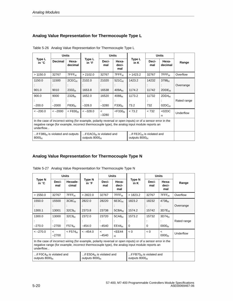
Analog Modules
5-20S7-400, M7-400 Programmable Controllers Module Specifications
A5E00069467-06
Analog Value Representation for Thermocouple Type L
Table 5-26 Analog Value Representation for Thermocouple Type L
Units Units UnitsType L
in C Decimal Hexa-decimal
Type L in F Deci-
malHexa-deci-mal
Type L in K Deci-
malHexa-
decimalRange
> 1150.0 32767 7FFFH > 2102.0 32767 7FFFH > 1423.2 32767 7FFFH Overflow
1150.0
:
901.0
11500
:
9010
2CECH
:
2332H
2102.0
:
1653.8
21020
:
16538
521CH
:
409AH
1423.2
:
1174.2
14232
:
11742
3798H
:
2DDEH
Overrange
900.0
:
–200.0
9000
:
–2000
2328H
:
F830H
1652.0
:
–328.0
16520
:
–3280
4088H
:
F330H
1173.2
:
73.2
11732
:
732
2DD4H
:
02DCH
Rated range
< –200.0 < –2000 < F830H < –328.0 <–3280
<F330H < 73.2 < 732 <02DCH
Underflow
In the case of incorrect wiring (for example, polarity reversal or open inputs) or of a sensor error in thenegative range (for example, incorrect thermocouple type), the analog input module reports anunderflow...
...if F380H is violated and outputs8000H
...if EAC0H is violated andoutputs 8000H
...if FE2CH is violated andoutputs 8000H
Analog Value Representation for Thermocouple Type N
Table 5-27 Analog Value Representation for Thermocouple Type N
Units Units UnitsType N
in C Deci-mal
Hexade-cimal
Type N in F Deci-
malHexa-deci-mal
Type N in K Deci-
malHexa-deci-mal
Range
> 1550.0 32767 7FFFH > 2822.0 32767 7FFFH > 1823.2 32767 7FFFH Overflow
1550.0
:
1300.1
15500
:
13001
3C8CH
:
32C9H
2822.0
:
2373.8
28220
:
23738
6E3CH
:
5CBAH
1823.2
:
1574.2
18232
:
15742
4738H
:
3D7EH
Overrange
1300.0
:
–270.0
13000
:
–2700
32C8H
:
F574H
2372.0
:
–454.0
23720
:
–4540
5CA8H
:
EE44H
1573.2
:
0
15732
:
0
3D74H
:
0000H
Rated range
< –270.0 <–2700
< F574H < –454.0 <–4540
<EE44H
< 0 < 0 <0000H
Underflow
In the case of incorrect wiring (for example, polarity reversal or open inputs) or of a sensor error in thenegative range (for example, incorrect thermocouple type), the analog input module reports anunderflow...
...if F0C4H is violated andoutputs 8000H
...if E5D4H is violated andoutputs 8000H
...if FB70H is violated andoutputs 8000H
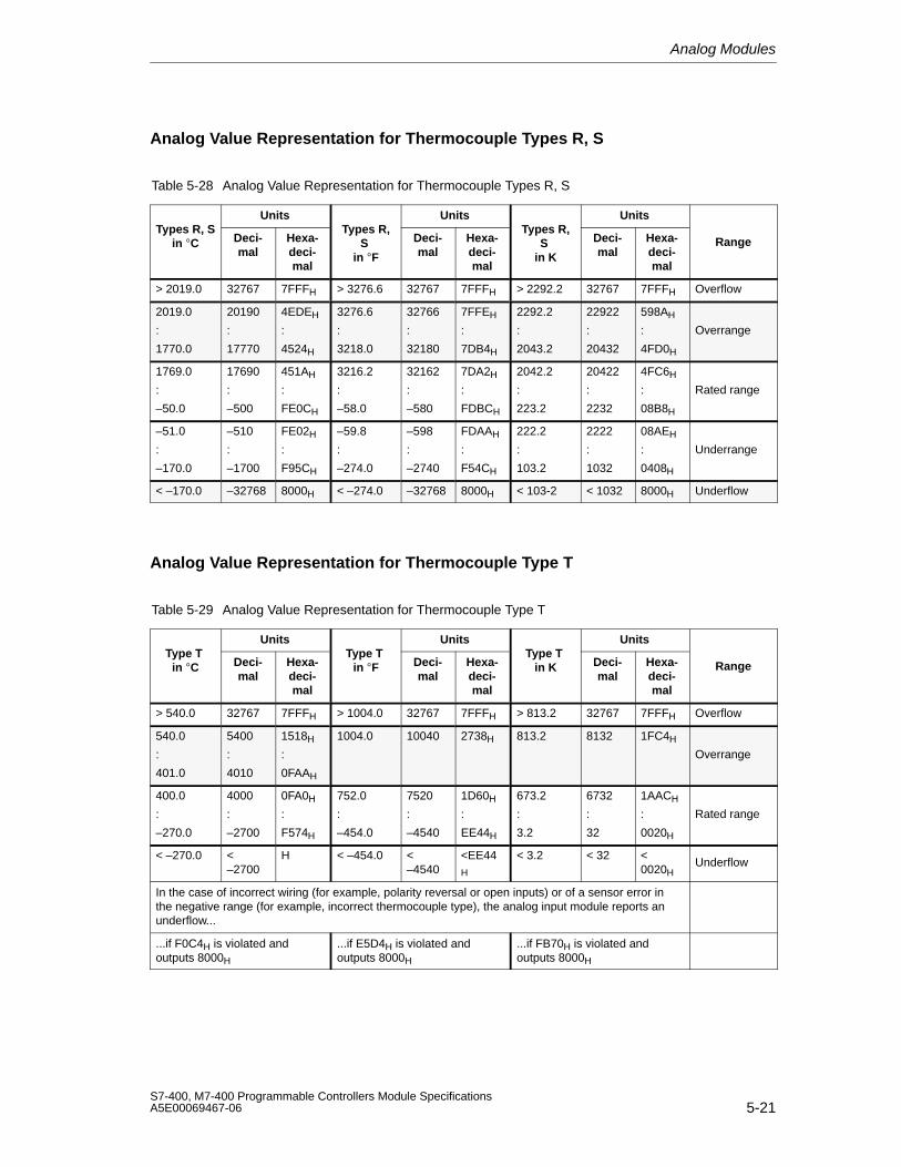
Analog Modules
5-21S7-400, M7-400 Programmable Controllers Module SpecificationsA5E00069467-06
Analog Value Representation for Thermocouple Types R, S
Table 5-28 Analog Value Representation for Thermocouple Types R, S
Units Units UnitsTypes R, S
in C Deci-mal
Hexa-deci-mal
Types R,S
in F
Deci-mal
Hexa-deci-mal
Types R,S
in K
Deci-mal
Hexa-deci-mal
Range
> 2019.0 32767 7FFFH > 3276.6 32767 7FFFH > 2292.2 32767 7FFFH Overflow
2019.0
:
1770.0
20190
:
17770
4EDEH
:
4524H
3276.6
:
3218.0
32766
:
32180
7FFEH
:
7DB4H
2292.2
:
2043.2
22922
:
20432
598AH
:
4FD0H
Overrange
1769.0
:
–50.0
17690
:
–500
451AH
:
FE0CH
3216.2
:
–58.0
32162
:
–580
7DA2H
:
FDBCH
2042.2
:
223.2
20422
:
2232
4FC6H
:
08B8H
Rated range
–51.0
:
–170.0
–510
:
–1700
FE02H
:
F95CH
–59.8
:
–274.0
–598
:
–2740
FDAAH
:
F54CH
222.2
:
103.2
2222
:
1032
08AEH
:
0408H
Underrange
< –170.0 –32768 8000H < –274.0 –32768 8000H < 103-2 < 1032 8000H Underflow
Analog Value Representation for Thermocouple Type T
Table 5-29 Analog Value Representation for Thermocouple Type T
Units Units UnitsType T
in C Deci-mal
Hexa-deci-mal
Type T in F Deci-
malHexa-deci-mal
Type T in K Deci-
malHexa-deci-mal
Range
> 540.0 32767 7FFFH > 1004.0 32767 7FFFH > 813.2 32767 7FFFH Overflow
540.0
:
401.0
5400
:
4010
1518H
:
0FAAH
1004.0 10040 2738H 813.2 8132 1FC4H
Overrange
400.0
:
–270.0
4000
:
–2700
0FA0H
:
F574H
752.0
:
–454.0
7520
:
–4540
1D60H
:
EE44H
673.2
:
3.2
6732
:
32
1AACH
:
0020H
Rated range
< –270.0 <–2700
H < –454.0 <–4540
<EE44H
< 3.2 < 32 <0020H
Underflow
In the case of incorrect wiring (for example, polarity reversal or open inputs) or of a sensor error inthe negative range (for example, incorrect thermocouple type), the analog input module reports anunderflow...
...if F0C4H is violated andoutputs 8000H
...if E5D4H is violated andoutputs 8000H
...if FB70H is violated andoutputs 8000H
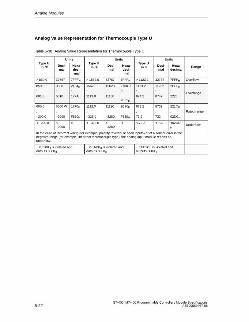
Analog Modules
5-22S7-400, M7-400 Programmable Controllers Module Specifications
A5E00069467-06
Analog Value Representation for Thermocouple Type U
Table 5-30 Analog Value Representation for Thermocouple Type U
Units Units UnitsType U
in C Deci-mal
Hexa-deci-mal
Type U in F Deci-
malHexa-deci-mal
Type U in K Deci-
malHexa-
decimalRange
> 850.0 32767 7FFFH > 1562.0 32767 7FFFH > 1123.2 32767 7FFFH Overflow
850.0
:
601.0
8500
:
6010
2134H
:
177AH
1562.0
:
1113.8
15620
:
11138
2738.0H
:
2B82H
1123.2
:
874.2
11232
:
8742
2BE0H
:
2226H
Overrange
600.0
:
–200.0
6000 W
:
–2000
1770H
:
F830H
1112.0
:
–328.0
11120
:
–3280
2B70H
:
F330H
873.2
:
73.2
8732
:
732
221CH
:
02DCH
Rated range
< –200.0 <–2000
H < –328.0 <–3280
H < 73.2 < 732 <02DCH
Underflow
In the case of incorrect wiring (for example, polarity reversal or open inputs) or of a sensor error in thenegative range (for example, incorrect thermocouple type), the analog input module reports anunderflow...
...if F380H is violated andoutputs 8000H
...if EAC0H is violated andoutputs 8000H
...if FE2CH is violated andoutputs 8000H
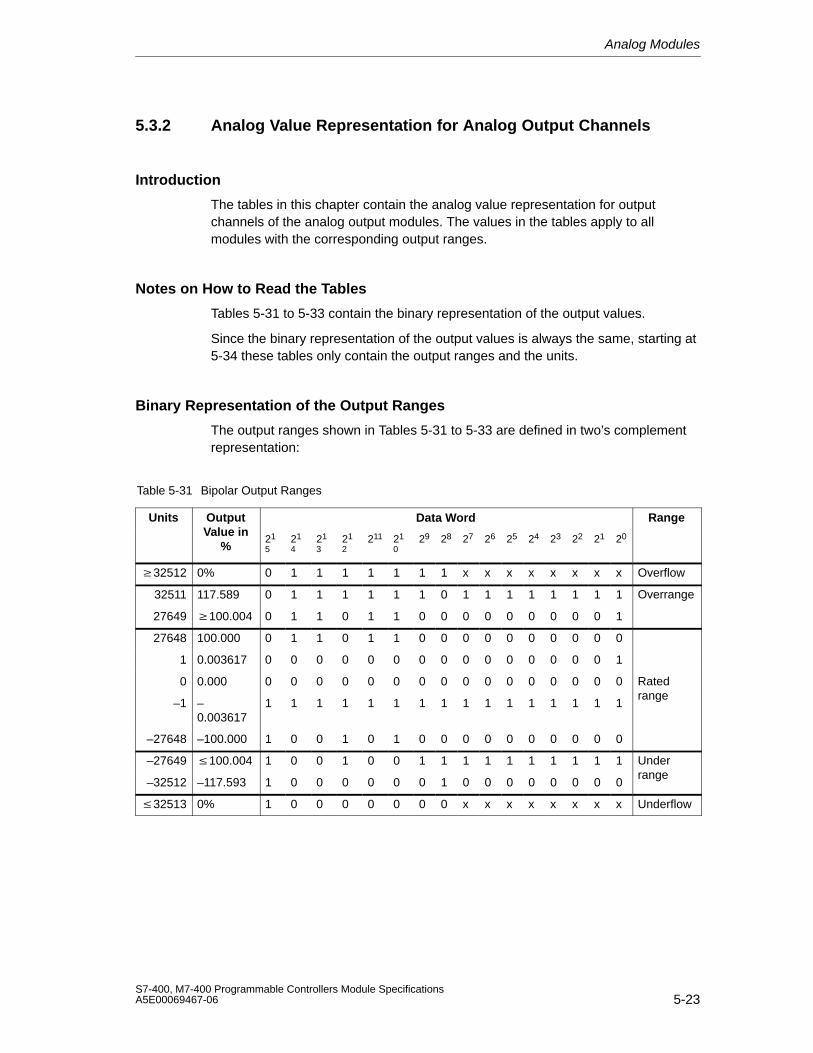
Analog Modules
5-23S7-400, M7-400 Programmable Controllers Module SpecificationsA5E00069467-06
5.3.2 Analog Value Representation for Analog Output Channels
Introduction
The tables in this chapter contain the analog value representation for outputchannels of the analog output modules. The values in the tables apply to allmodules with the corresponding output ranges.
Notes on How to Read the Tables
Tables 5-31 to 5-33 contain the binary representation of the output values.
Since the binary representation of the output values is always the same, starting at5-34 these tables only contain the output ranges and the units.
Binary Representation of the Output Ranges
The output ranges shown in Tables 5-31 to 5-33 are defined in two’s complementrepresentation:
Table 5-31 Bipolar Output Ranges
Units Output Data Word RangeValue in
%21
521
421
321
2211 21
029 28 27 26 25 24 23 22 21 20
32512 0% 0 1 1 1 1 1 1 1 x x x x x x x x Overflow
32511 117.589 0 1 1 1 1 1 1 0 1 1 1 1 1 1 1 1 Overrange
27649 100.004 0 1 1 0 1 1 0 0 0 0 0 0 0 0 0 1
27648 100.000 0 1 1 0 1 1 0 0 0 0 0 0 0 0 0 0
1 0.003617 0 0 0 0 0 0 0 0 0 0 0 0 0 0 0 1
0 0.000 0 0 0 0 0 0 0 0 0 0 0 0 0 0 0 0 Rated
–1 –0.003617
1 1 1 1 1 1 1 1 1 1 1 1 1 1 1 1range
–27648 –100.000 1 0 0 1 0 1 0 0 0 0 0 0 0 0 0 0
–27649 100.004 1 0 0 1 0 0 1 1 1 1 1 1 1 1 1 1 Under
–32512 –117.593 1 0 0 0 0 0 0 1 0 0 0 0 0 0 0 0range
32513 0% 1 0 0 0 0 0 0 0 x x x x x x x x Underflow
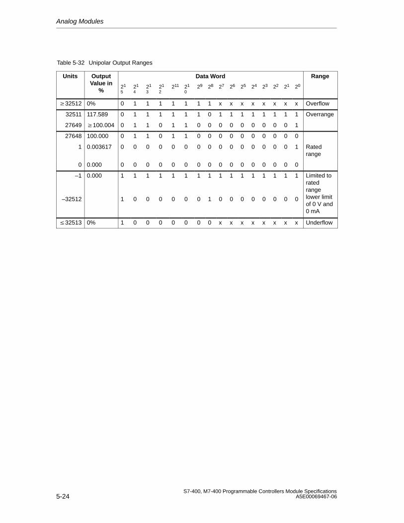
Analog Modules
5-24S7-400, M7-400 Programmable Controllers Module Specifications
A5E00069467-06
Table 5-32 Unipolar Output Ranges
Units Output Data Word RangeValue in
%21
521
421
321
2211 21
029 28 27 26 25 24 23 22 21 20
32512 0% 0 1 1 1 1 1 1 1 x x x x x x x x Overflow
32511 117.589 0 1 1 1 1 1 1 0 1 1 1 1 1 1 1 1 Overrange
27649 100.004 0 1 1 0 1 1 0 0 0 0 0 0 0 0 0 1
27648 100.000 0 1 1 0 1 1 0 0 0 0 0 0 0 0 0 0
1 0.003617 0 0 0 0 0 0 0 0 0 0 0 0 0 0 0 1 Ratedrange
0 0.000 0 0 0 0 0 0 0 0 0 0 0 0 0 0 0 0
–1 0.000 1 1 1 1 1 1 1 1 1 1 1 1 1 1 1 1 Limited toratedrange
–32512 1 0 0 0 0 0 0 1 0 0 0 0 0 0 0 0 lower limitof 0 V and0 mA
32513 0% 1 0 0 0 0 0 0 0 x x x x x x x x Underflow
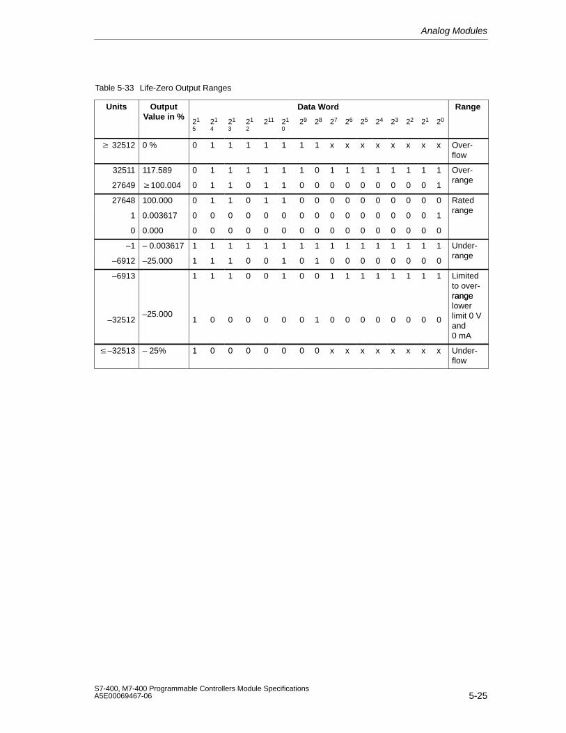
Analog Modules
5-25S7-400, M7-400 Programmable Controllers Module SpecificationsA5E00069467-06
Table 5-33 Life-Zero Output Ranges
Units Output Data Word RangeValue in %
21
521
421
321
2211 21
029 28 27 26 25 24 23 22 21 20
32512 0 % 0 1 1 1 1 1 1 1 x x x x x x x x Over-flow
32511 117.589 0 1 1 1 1 1 1 0 1 1 1 1 1 1 1 1 Over-
27649 100.004 0 1 1 0 1 1 0 0 0 0 0 0 0 0 0 1range
27648 100.000 0 1 1 0 1 1 0 0 0 0 0 0 0 0 0 0 Rated
1 0.003617 0 0 0 0 0 0 0 0 0 0 0 0 0 0 0 1range
0 0.000 0 0 0 0 0 0 0 0 0 0 0 0 0 0 0 0
–1 – 0.003617 1 1 1 1 1 1 1 1 1 1 1 1 1 1 1 1 Under-
–6912 –25.000 1 1 1 0 0 1 0 1 0 0 0 0 0 0 0 0range
–6913 1 1 1 0 0 1 0 0 1 1 1 1 1 1 1 1 Limitedto over-range
–32512–25.000
1 0 0 0 0 0 0 1 0 0 0 0 0 0 0 0
rangelowerlimit 0 Vand0 mA
–32513 – 25% 1 0 0 0 0 0 0 0 x x x x x x x x Under-flow
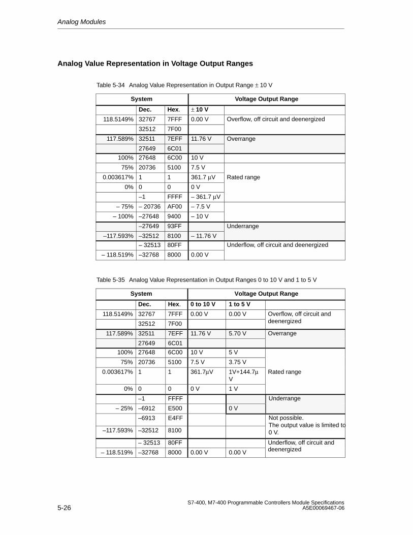
Analog Modules
5-26S7-400, M7-400 Programmable Controllers Module Specifications
A5E00069467-06
Analog Value Representation in Voltage Output Ranges
Table 5-34 Analog Value Representation in Output Range ± 10 V
System Voltage Output Range
Dec. Hex. ± 10 V
118.5149% 32767 7FFF 0.00 V Overflow, off circuit and deenergized
32512 7F00
117.589% 32511 7EFF 11.76 V Overrange
27649 6C01
100% 27648 6C00 10 V
75% 20736 5100 7.5 V
0.003617% 1 1 361.7 µV Rated range
0% 0 0 0 V
–1 FFFF – 361.7 µV
– 75% – 20736 AF00 – 7.5 V
– 100% –27648 9400 – 10 V
–27649 93FF Underrange
–117.593% –32512 8100 – 11.76 V
– 32513 80FF Underflow, off circuit and deenergized
– 118.519% –32768 8000 0.00 V
Table 5-35 Analog Value Representation in Output Ranges 0 to 10 V and 1 to 5 V
System Voltage Output Range
Dec. Hex. 0 to 10 V 1 to 5 V
118.5149% 32767 7FFF 0.00 V 0.00 V Overflow, off circuit and
32512 7F00 deenergized
117.589% 32511 7EFF 11.76 V 5.70 V Overrange
27649 6C01
100% 27648 6C00 10 V 5 V
75% 20736 5100 7.5 V 3.75 V
0.003617% 1 1 361.7µV 1V+144.7µV
Rated range
0% 0 0 0 V 1 V
–1 FFFF Underrange
– 25% –6912 E500 0 V
–6913 E4FF Not possible.
–117.593% –32512 8100The output value is limited to0 V.
– 32513 80FF Underflow, off circuit and
– 118.519% –32768 8000 0.00 V 0.00 V deenergized
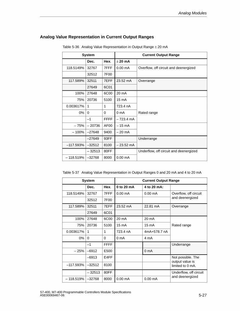
Analog Modules
5-27S7-400, M7-400 Programmable Controllers Module SpecificationsA5E00069467-06
Analog Value Representation in Current Output Ranges
Table 5-36 Analog Value Representation in Output Range ± 20 mA
System Current Output Range
Dec. Hex. ± 20 mA
118.5149% 32767 7FFF 0.00 mA Overflow, off circuit and deenergized
32512 7F00
117.589% 32511 7EFF 23.52 mA Overrange
27649 6C01
100% 27648 6C00 20 mA
75% 20736 5100 15 mA
0.003617% 1 1 723.4 nA
0% 0 0 0 mA Rated range
–1 FFFF – 723.4 mA
– 75% – 20736 AF00 – 15 mA
– 100% –27648 9400 – 20 mA
–27649 93FF Underrange
–117.593% –32512 8100 – 23.52 mA
– 32513 80FF Underflow, off circuit and deenergized
– 118.519% –32768 8000 0.00 mA
Table 5-37 Analog Value Representation in Output Ranges 0 and 20 mA and 4 to 20 mA
System Current Output Range
Dec. Hex. 0 to 20 mA 4 to 20 mA:
118.5149% 32767 7FFF 0.00 mA 0.00 mA Overflow, off circuit
32512 7F00and deenergized
117.589% 32511 7EFF 23.52 mA 22.81 mA Overrange
27649 6C01
100% 27648 6C00 20 mA 20 mA
75% 20736 5100 15 mA 15 mA Rated range
0.003617% 1 1 723.4 nA 4mA+578.7 nA
0% 0 0 0 mA 4 mA
–1 FFFF Underrange
– 25% –6912 E500 0 mA
–6913 E4FF Not possible. The
–117.593% –32512 8100output value islimited to 0 mA.
– 32513 80FF Underflow, off circuit
– 118.519% –32768 8000 0.00 mA 0.00 mAand deenergized
Analog Modules
5-28S7-400, M7-400 Programmable Controllers Module Specifications
A5E00069467-06
5.4 Setting the Measuring Method and Measuring Rangesof the Analog Input Channels
Two Procedures
There are two procedures for setting the measuring method and the measuringranges of the analog input channels of the analog modules:
• With a measuring range module and STEP 7
• By wiring the analog input channel and STEP 7
Which of these two methods is used for the individual analog modules depends onthe module and is described in detail in the specific module sections.
The procedure for setting the measuring method and measuring range of themodule in STEP 7 is described in Section 5.7.
The following section describes how you set the measuring method and themeasuring range by means of measuring range modules.
Setting the Measuring Method and the Measuring Ranges with Measuring RangeModules
If the analog modules have measuring range modules, they are supplied with themeasuring range modules plugged in.
If necessary, the measuring range modules must be replugged to change themeasuring method and the measuring range.
Attention
Make sure that the measuring range modules are on the side of the analog inputmodule.
Before installing the analog input module, therefore, check whether the measuringrange modules have to be set to another measuring method and anothermeasuring range.
Possible Settings for the Measuring Range Modules
The measuring range modules can be set to the following positions: “A”, “B”, “C” and“D”.
Which measuring range module positions you must select for the individualmeasuring methods and measuring ranges is described in detail in the specificmodule section.
The settings for the various types of measurement and measuring ranges are alsoprinted on the analog module.
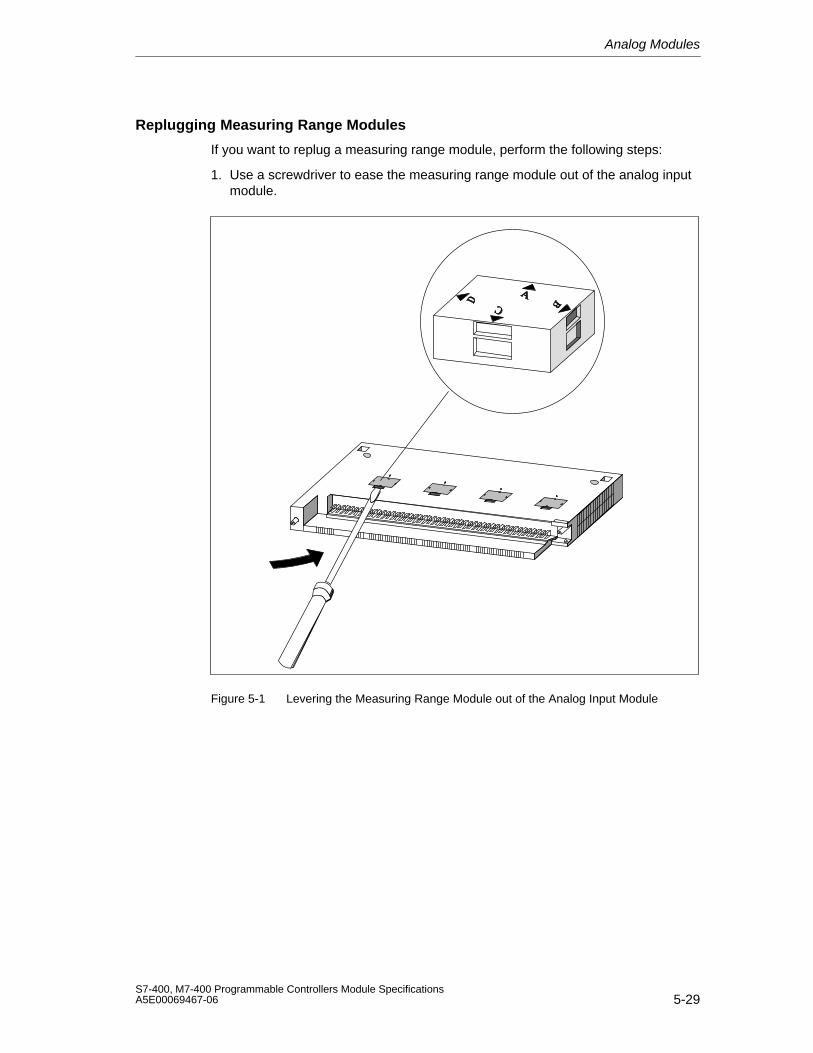
Analog Modules
5-29S7-400, M7-400 Programmable Controllers Module SpecificationsA5E00069467-06
Replugging Measuring Range Modules
If you want to replug a measuring range module, perform the following steps:
1. Use a screwdriver to ease the measuring range module out of the analog inputmodule.
Figure 5-1 Levering the Measuring Range Module out of the Analog Input Module
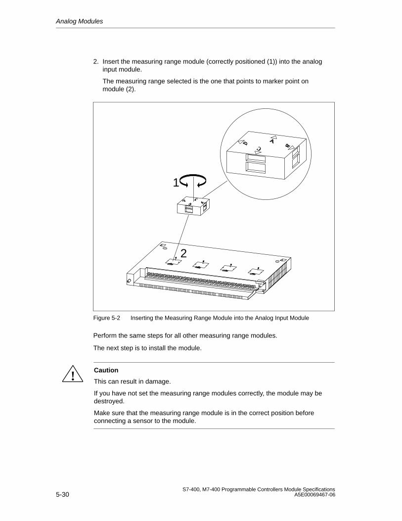
Analog Modules
5-30S7-400, M7-400 Programmable Controllers Module Specifications
A5E00069467-06
2. Insert the measuring range module (correctly positioned (1)) into the analoginput module.
The measuring range selected is the one that points to marker point onmodule (2).
1
2
Figure 5-2 Inserting the Measuring Range Module into the Analog Input Module
Perform the same steps for all other measuring range modules.
The next step is to install the module.
!Caution
This can result in damage.
If you have not set the measuring range modules correctly, the module may bedestroyed.
Make sure that the measuring range module is in the correct position beforeconnecting a sensor to the module.
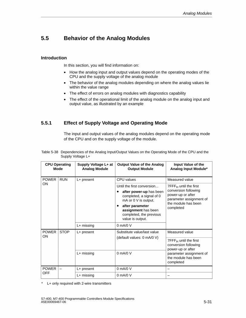
Analog Modules
5-31S7-400, M7-400 Programmable Controllers Module SpecificationsA5E00069467-06
5.5 Behavior of the Analog Modules
Introduction
In this section, you will find information on:
• How the analog input and output values depend on the operating modes of theCPU and the supply voltage of the analog module
• The behavior of the analog modules depending on where the analog values liewithin the value range
• The effect of errors on analog modules with diagnostics capability
• The effect of the operational limit of the analog module on the analog input andoutput value, as illustrated by an example
5.5.1 Effect of Supply Voltage and Operating Mode
The input and output values of the analog modules depend on the operating modeof the CPU and on the supply voltage of the module.
Table 5-38 Dependencies of the Analog Input/Output Values on the Operating Mode of the CPU and theSupply Voltage L+
CPU OperatingMode
Supply Voltage L+ atAnalog Module
Output Value of the AnalogOutput Module
Input Value of theAnalog Input Module*
POWER RUN L+ present CPU values Measured valueON
Until the first conversion...
• after power-up has beencompleted, a signal of 0mA or 0 V is output.
• after parameterassignment has beencompleted, the previousvalue is output.
7FFFH until the firstconversion followingpower-up or afterparameter assignment ofthe module has beencompleted
L+ missing 0 mA/0 V
POWER STOP L+ present Substitute value/last value Measured valueON (default values: 0 mA/0 V)
7FFFH until the firstconversion following
L+ missing 0 mA/0 Vpower-up or afterparameter assignment ofthe module has beencompleted
POWER – L+ present 0 mA/0 V –OFF
L+ missing 0 mA/0 V –
* L+ only required with 2-wire transmitters
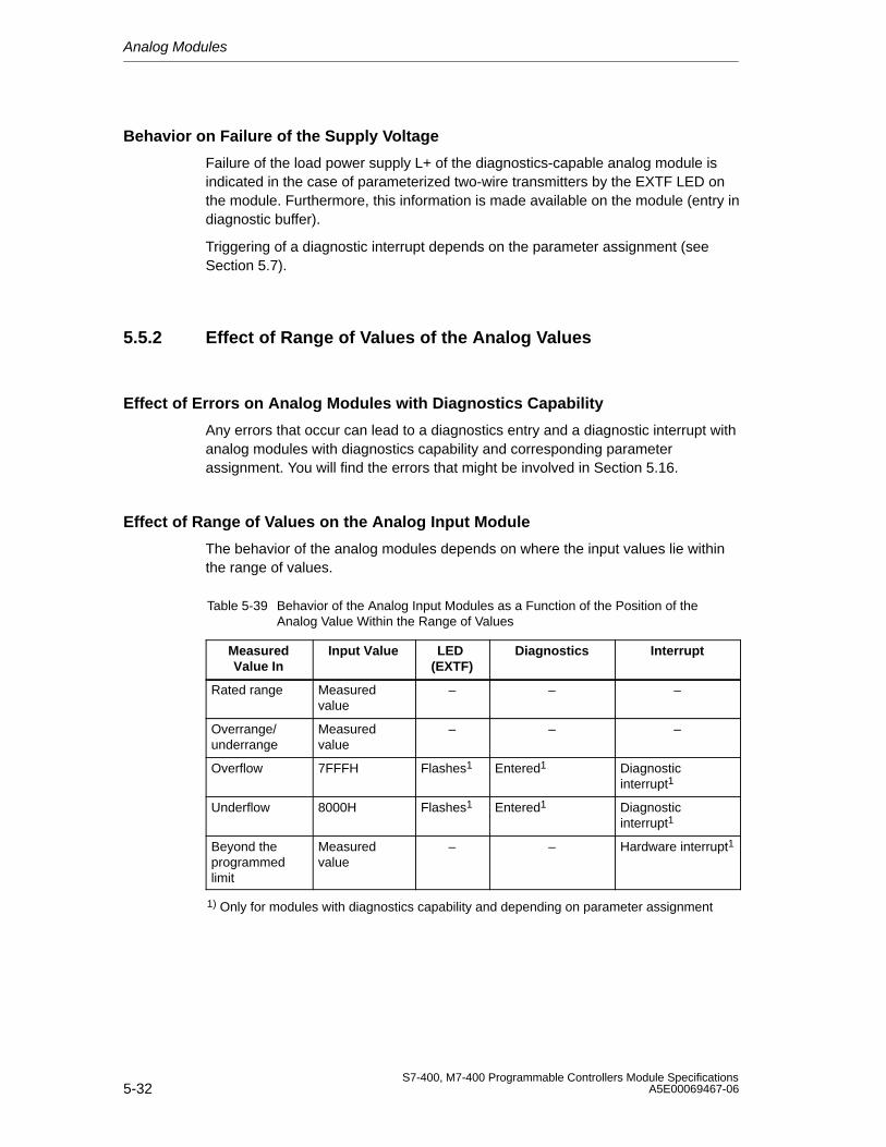
Analog Modules
5-32S7-400, M7-400 Programmable Controllers Module Specifications
A5E00069467-06
Behavior on Failure of the Supply Voltage
Failure of the load power supply L+ of the diagnostics-capable analog module isindicated in the case of parameterized two-wire transmitters by the EXTF LED onthe module. Furthermore, this information is made available on the module (entry indiagnostic buffer).
Triggering of a diagnostic interrupt depends on the parameter assignment (seeSection 5.7).
5.5.2 Effect of Range of Values of the Analog Values
Effect of Errors on Analog Modules with Diagnostics Capability
Any errors that occur can lead to a diagnostics entry and a diagnostic interrupt withanalog modules with diagnostics capability and corresponding parameterassignment. You will find the errors that might be involved in Section 5.16.
Effect of Range of Values on the Analog Input Module
The behavior of the analog modules depends on where the input values lie withinthe range of values.
Table 5-39 Behavior of the Analog Input Modules as a Function of the Position of theAnalog Value Within the Range of Values
MeasuredValue In
Input Value LED (EXTF)
Diagnostics Interrupt
Rated range Measuredvalue
– – –
Overrange/underrange
Measuredvalue
– – –
Overflow 7FFFH Flashes1 Entered1 Diagnosticinterrupt1
Underflow 8000H Flashes1 Entered1 Diagnosticinterrupt1
Beyond theprogrammedlimit
Measuredvalue
– – Hardware interrupt1
1) Only for modules with diagnostics capability and depending on parameter assignment
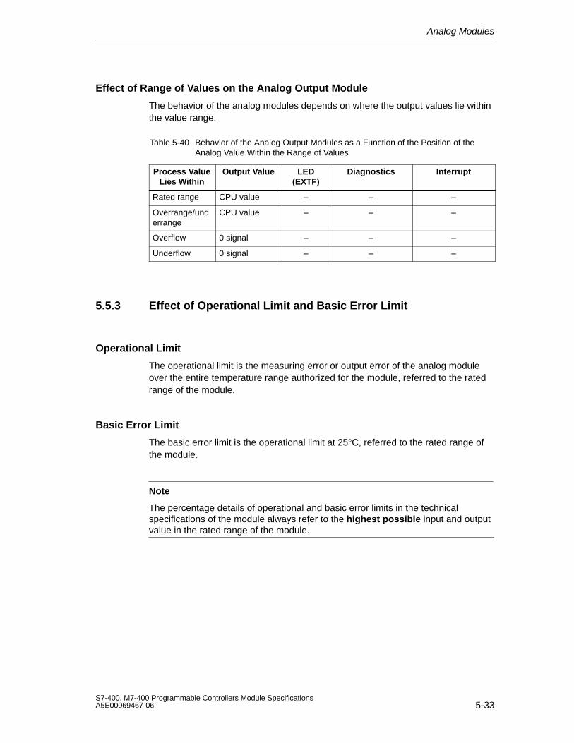
Analog Modules
5-33S7-400, M7-400 Programmable Controllers Module SpecificationsA5E00069467-06
Effect of Range of Values on the Analog Output Module
The behavior of the analog modules depends on where the output values lie withinthe value range.
Table 5-40 Behavior of the Analog Output Modules as a Function of the Position of theAnalog Value Within the Range of Values
Process ValueLies Within
Output Value LED(EXTF)
Diagnostics Interrupt
Rated range CPU value – – –
Overrange/underrange
CPU value – – –
Overflow 0 signal – – –
Underflow 0 signal – – –
5.5.3 Effect of Operational Limit and Basic Error Limit
Operational Limit
The operational limit is the measuring error or output error of the analog moduleover the entire temperature range authorized for the module, referred to the ratedrange of the module.
Basic Error Limit
The basic error limit is the operational limit at 25°C, referred to the rated range ofthe module.
Note
The percentage details of operational and basic error limits in the technicalspecifications of the module always refer to the highest possible input and outputvalue in the rated range of the module.
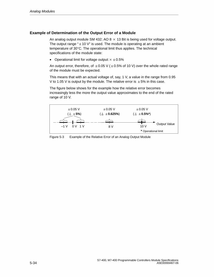
Analog Modules
5-34S7-400, M7-400 Programmable Controllers Module Specifications
A5E00069467-06
Example of Determination of the Output Error of a Module
An analog output module SM 432; AO 8 13 Bit is being used for voltage output.The output range “10 V” is used. The module is operating at an ambienttemperature of 30°C. The operational limit thus applies. The technicalspecifications of the module state:
• Operational limit for voltage output:0.5%
An output error, therefore, of 0.05 V (0.5% of 10 V) over the whole rated rangeof the module must be expected.
This means that with an actual voltage of, say, 1 V, a value in the range from 0.95V to 1.05 V is output by the module. The relative error is 5% in this case.
The figure below shows for the example how the relative error becomesincreasingly less the more the output value approximates to the end of the ratedrange of 10 V.
( 0.5%*)
1 V0 V
( 0.625%)
Output Value
( 5%)
8 V 10 V
* Operational limit
–1 V
0.05 V0.05 V0.05 V
Figure 5-3 Example of the Relative Error of an Analog Output Module
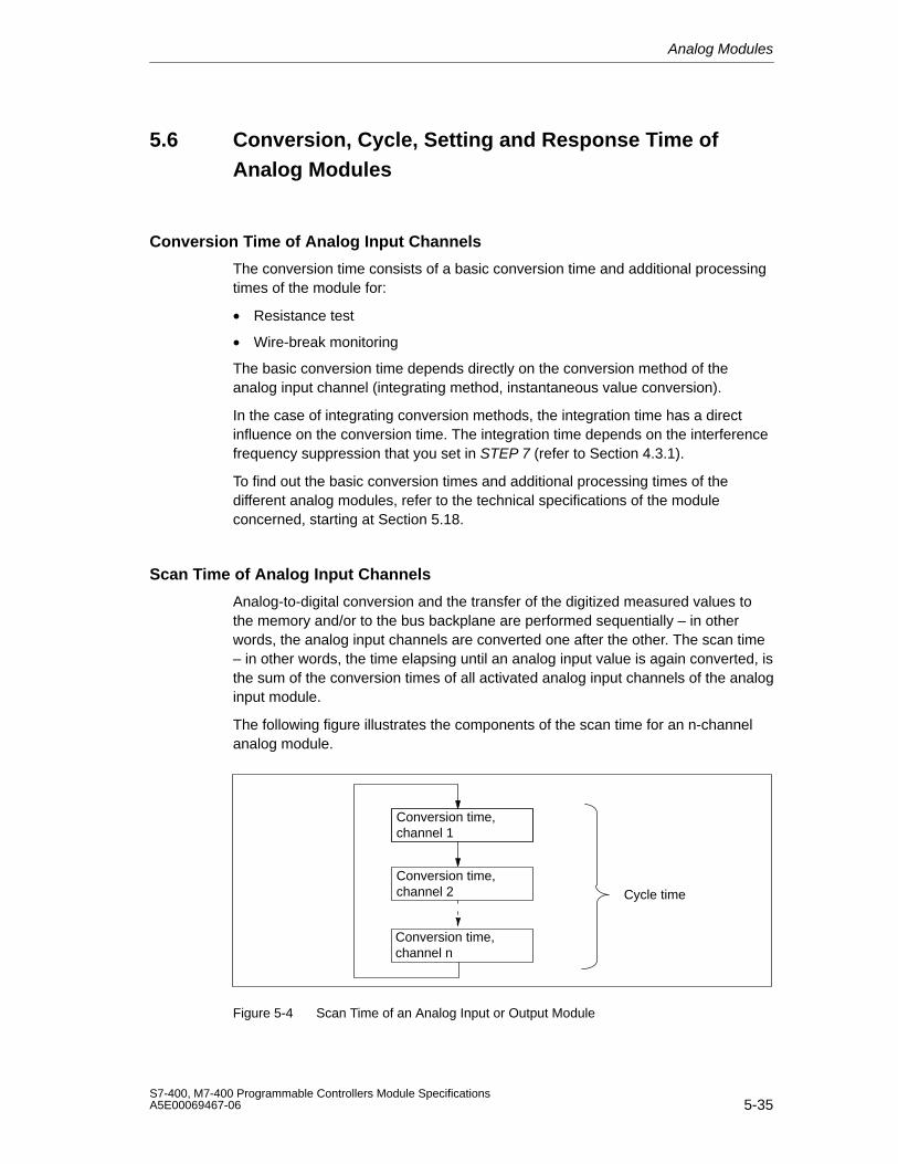
Analog Modules
5-35S7-400, M7-400 Programmable Controllers Module SpecificationsA5E00069467-06
5.6 Conversion, Cycle, Setting and Response Time ofAnalog Modules
Conversion Time of Analog Input Channels
The conversion time consists of a basic conversion time and additional processingtimes of the module for:
• Resistance test
• Wire-break monitoring
The basic conversion time depends directly on the conversion method of theanalog input channel (integrating method, instantaneous value conversion).
In the case of integrating conversion methods, the integration time has a directinfluence on the conversion time. The integration time depends on the interferencefrequency suppression that you set in STEP 7 (refer to Section 4.3.1).
To find out the basic conversion times and additional processing times of thedifferent analog modules, refer to the technical specifications of the moduleconcerned, starting at Section 5.18.
Scan Time of Analog Input Channels
Analog-to-digital conversion and the transfer of the digitized measured values tothe memory and/or to the bus backplane are performed sequentially – in otherwords, the analog input channels are converted one after the other. The scan time– in other words, the time elapsing until an analog input value is again converted, isthe sum of the conversion times of all activated analog input channels of the analoginput module.
The following figure illustrates the components of the scan time for an n-channelanalog module.
Conversion time, channel 1
Conversion time, channel 2
Conversion time, channel n
Cycle time
Figure 5-4 Scan Time of an Analog Input or Output Module
Analog Modules
5-36S7-400, M7-400 Programmable Controllers Module Specifications
A5E00069467-06
Basic Execution Time of the Analog Input Channels
The basic execution time corresponds to the cycle time for all the enabledchannels.
Setting the Smoothing of Analog Values
You can set the smoothing of the analog values in STEP 7 for some analog inputmodules.
Using Smoothing
Smoothing of analog values ensures a stable analog signal for further processing.
It makes sense to smooth the analog values with slow variations of measuredvalues – for example, with temperature measurements.
Smoothing Principle
The measured values are smoothed by digital filtering. Smoothing is accomplishedby the module calculating average values from a defined number of converted(digitized) analog values.
The user assigns parameters to smoothing at not more than four levels (none, low,average, high). The level determines the number of analog signals used foraveraging.
The higher the smoothing level chosen, the more stable is the smoothed analogvalue and the longer it takes until the smoothed analog signal is applied after astep response (refer to the following example).
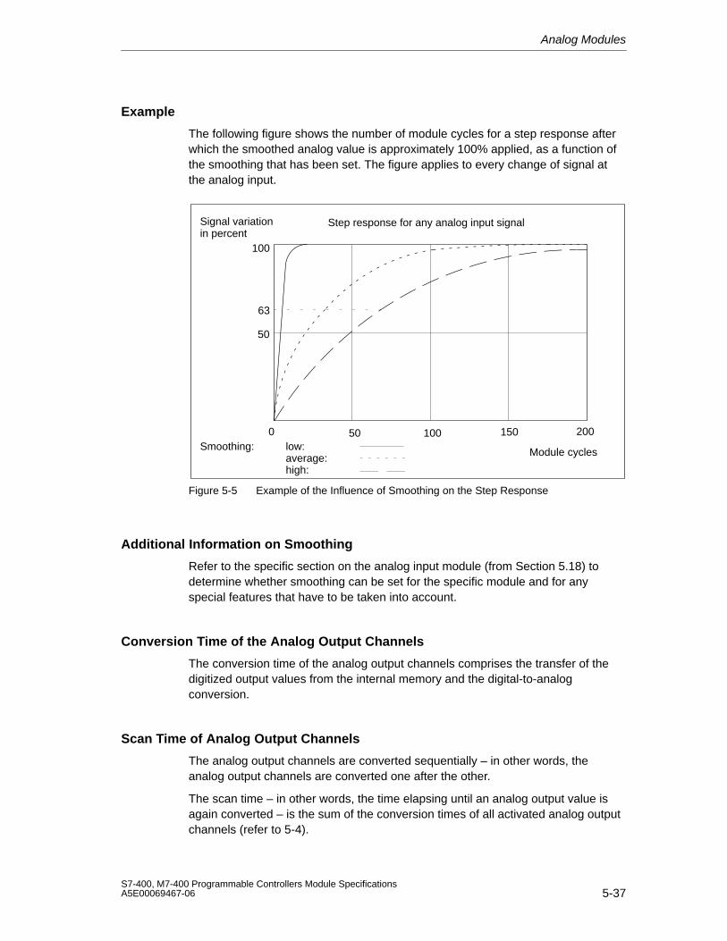
Analog Modules
5-37S7-400, M7-400 Programmable Controllers Module SpecificationsA5E00069467-06
Example
The following figure shows the number of module cycles for a step response afterwhich the smoothed analog value is approximately 100% applied, as a function ofthe smoothing that has been set. The figure applies to every change of signal atthe analog input.
50
100
0
63
50 100 150 200Smoothing: low:
average:high:
Module cycles
Signal variationin percent
Step response for any analog input signal
Figure 5-5 Example of the Influence of Smoothing on the Step Response
Additional Information on Smoothing
Refer to the specific section on the analog input module (from Section 5.18) todetermine whether smoothing can be set for the specific module and for anyspecial features that have to be taken into account.
Conversion Time of the Analog Output Channels
The conversion time of the analog output channels comprises the transfer of thedigitized output values from the internal memory and the digital-to-analogconversion.
Scan Time of Analog Output Channels
The analog output channels are converted sequentially – in other words, theanalog output channels are converted one after the other.
The scan time – in other words, the time elapsing until an analog output value isagain converted – is the sum of the conversion times of all activated analog outputchannels (refer to 5-4).
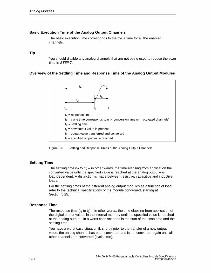
Analog Modules
5-38S7-400, M7-400 Programmable Controllers Module Specifications
A5E00069467-06
Basic Execution Time of the Analog Output Channels
The basic execution time corresponds to the cycle time for all the enabledchannels.
TipYou should disable any analog channels that are not being used to reduce the scantime in STEP 7.
Overview of the Settling Time and Response Time of the Analog Output Modules
tA
tZ
tE
t1 t2
tA = response time
tZ = cycle time corresponds to n conversion time (n = activated channels)
tE = settling time
t1 = new output value is present
t2 = output value transferred and converted
t3 = specified output value reached
t3
Figure 5-6 Settling and Response Times of the Analog Output Channels
Settling TimeThe settling time (t2 to t3) – in other words, the time elapsing from application theconverted value until the specified value is reached at the analog output – isload-dependent. A distinction is made between resistive, capacitive and inductiveloads.
For the settling times of the different analog output modules as a function of loadrefer to the technical specifications of the module concerned, starting atSection 5.25.
Response TimeThe response time (t1 to t3) – in other words, the time elapsing from application ofthe digital output values in the internal memory until the specified value is reachedat the analog output – in a worst case scenario is the sum of the scan time and thesettling time.
You have a worst case situation if, shortly prior to the transfer of a new outputvalue, the analog channel has been converted and is not converted again until allother channels are converted (cycle time).
Analog Modules
5-39S7-400, M7-400 Programmable Controllers Module SpecificationsA5E00069467-06
5.7 Analog Module Parameter Assignment
Introduction
Analog modules can have different characteristics. You can set the characteristicsof the modules by means of parameter assignment.
Tools for Parameter Assignment
You assign parameters to analog modules with STEP 7. You must performparameter assignment in STOP mode of the CPU.
When you have set all the parameters, download the parameters from theprogramming device to the CPU. When there is a transition from STOP to RUNmode, the CPU transfers the parameters to the individual analog modules.
In addition, if necessary you must place the measuring range modules of themodule in the necessary position (refer to Section 5.4).
Static and Dynamic Parameters
The parameters are divided into static and dynamic parameters.
Set the static parameters in STOP mode of the CPU, as described above.
You can similarly modify the dynamic parameters in the current user program bymeans of SFCs. Note, however, that after a change from RUN STOP, STOP RUN of the CPU, the parameters set in STEP 7 apply again. You will find adescription of the parameter assignment of modules in the user program inAppendix A.
Table 5-41 Static and dynamic parameters of the analog groups
Parameter Settable with CPU OperatingMode
Static PG (STEP 7 HWCONFIG) STOP
Dynamic PG (STEP 7 HWCONFIG) STOP
SFC 55 in the user program RUN
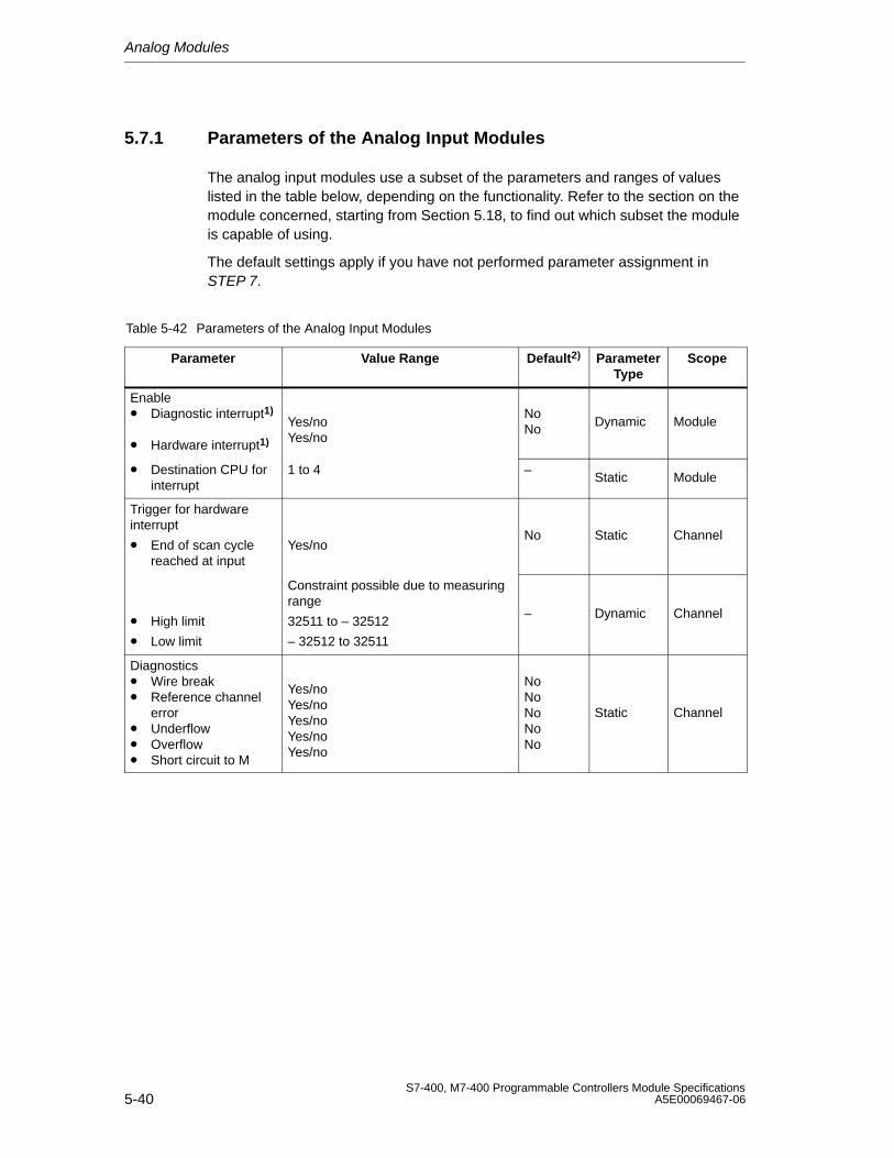
Analog Modules
5-40S7-400, M7-400 Programmable Controllers Module Specifications
A5E00069467-06
5.7.1 Parameters of the Analog Input Modules
The analog input modules use a subset of the parameters and ranges of valueslisted in the table below, depending on the functionality. Refer to the section on themodule concerned, starting from Section 5.18, to find out which subset the moduleis capable of using.
The default settings apply if you have not performed parameter assignment inSTEP 7.
Table 5-42 Parameters of the Analog Input Modules
Parameter Value Range Default2) ParameterType
Scope
Enable• Diagnostic interrupt1)
• Hardware interrupt1)
Yes/noYes/no
NoNo
Dynamic Module
• Destination CPU forinterrupt
1 to 4 –Static Module
Trigger for hardwareinterrupt
• End of scan cyclereached at input
Yes/noNo Static Channel
• High limit
• Low limit
Constraint possible due to measuring range
32511 to – 32512
– 32512 to 32511
– Dynamic Channel
Diagnostics • Wire break • Reference channel
error• Underflow• Overflow• Short circuit to M
Yes/noYes/noYes/noYes/noYes/no
NoNoNoNoNo
Static Channel
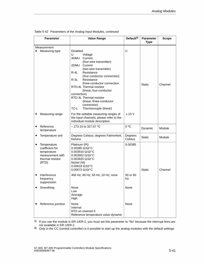
Analog Modules
5-41S7-400, M7-400 Programmable Controllers Module SpecificationsA5E00069467-06
Table 5-42 Parameters of the Analog Input Modules, continued
Parameter ScopeParameterType
Default2)Value Range
Measurement• Measuring type Disabled
U Voltage4DMU Current
(four-wire transmitter)2DMU Current
(two-wire transmitter)R-4L Resistance
(four-conductor connection)R-3L Resistance
three-conductor connectionRTD-4L Thermal resistor
(linear, four-conductorconnection)RTD-3L Thermal resistor
(linear, three-conductor connection)
TC-L Thermocouple (linear)
U
Static Channel
• Measuring range For the settable measuring ranges ofthe input channels, please refer to theindividual module description.
10 V
• Referencetemperature
– 273.15 to 327.67 oC 0 oCDynamic Module
• Temperature unit Degrees Celsius; degrees Fahrenheit;Kelvins
DegreesCelsius
Static Module
• Temperaturecoefficient fortemperaturemeasurement withthermal resistor(RTD)
Platinum (Pt)0.00385 /°C0.003916 /°C0.003902 /°C0.003920 /°CNickel (Ni)0.00618 /°C0.00672 /°C
0.00385
Static Channel
• Interferencefrequencysuppression
400 Hz; 60 Hz; 50 Hz; 10 Hz; none 50 or 60Hz
• Smoothing NoneLowAverageHigh
None
• Reference junction NoneInternalRTD on channel 0Reference temperature value dynamic
None
1) If you use the module in ER-1/ER-2, you must set this parameter to “No” because the interrupt lines arenot available in ER-1/ER-2.
2) Only in the CC (central controller) is it possible to start up the analog modules with the default settings.
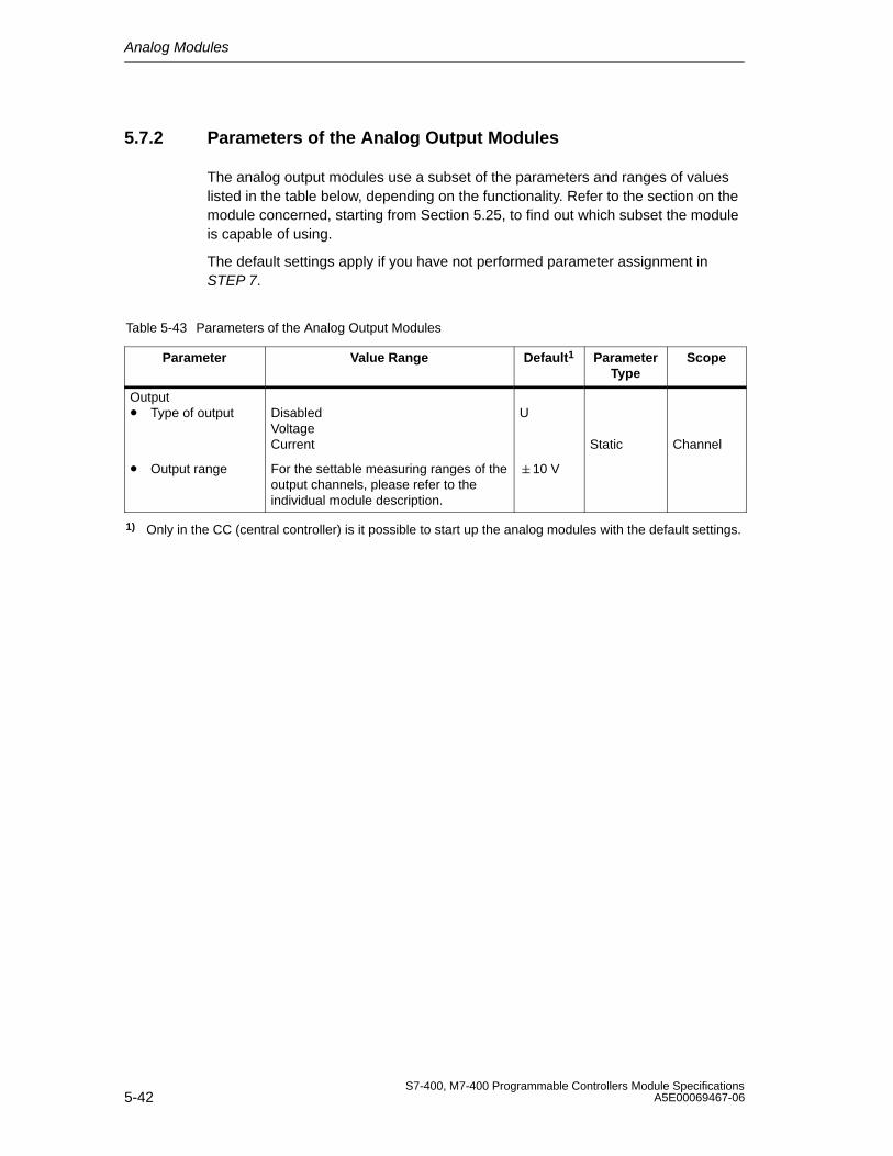
Analog Modules
5-42S7-400, M7-400 Programmable Controllers Module Specifications
A5E00069467-06
5.7.2 Parameters of the Analog Output Modules
The analog output modules use a subset of the parameters and ranges of valueslisted in the table below, depending on the functionality. Refer to the section on themodule concerned, starting from Section 5.25, to find out which subset the moduleis capable of using.
The default settings apply if you have not performed parameter assignment inSTEP 7.
Table 5-43 Parameters of the Analog Output Modules
Parameter Value Range Default1 ParameterType
Scope
Output• Type of output Disabled
VoltageCurrent
U
Static Channel
• Output range For the settable measuring ranges of theoutput channels, please refer to theindividual module description.
10 V
1) Only in the CC (central controller) is it possible to start up the analog modules with the default settings.
Analog Modules
5-43S7-400, M7-400 Programmable Controllers Module SpecificationsA5E00069467-06
5.8 Connecting Sensors to Analog Inputs
Introduction
You can connect different sensors to the analog input modules depending on themeasuring method; voltage and current sensors, and resistors.
This section contains general information that is generally applicable to all theconnection options for sensors described in the sections that follow.
Cables for Analog Signals
To reduce electrical interference, you should use twisted-pair shielded cables forthe analog signals. The shield of the analog signal cables should be grounded atboth cable ends.
If there are potential differences between the cable ends, an equipotential bondingcurrent can flow over the shield, which leads to an interference of the analogsignals. In such a case, you should ground the shield at one end of the cable only.
Non-Isolated Analog Input Modules
In the case of the non-isolated analog input modules there is an electricalconnection between the reference point of the measuring circuit MANA and chassisground.
You use non-isolated analog modules if there are few or no potential differencesbetween the measuring sensors and chassis ground.
Isolated Analog Input Modules
With the isolated analog input modules there is no electrical connection betweenthe reference point of the measuring circuit MANA and chassis ground.
You use isolated analog input modules if a potential difference UISO can occurbetween the reference point of the measuring circuit MANA and chassis ground. Bymeans of an equipotential bonding conductor between the MANA terminal andchassis ground, make sure that UISO does not exceed the permitted value.
Limited Potential Difference UCM
Only a limited potential difference UCM (common mode voltage) may occuramongst the M– measuring lines of the input channels and between the leads andthe reference point of the measuring circuit MANA. In order to prevent thepermissible value from being exceeded, you must take different actions, describedbelow, depending on the potential connection of the sensors.
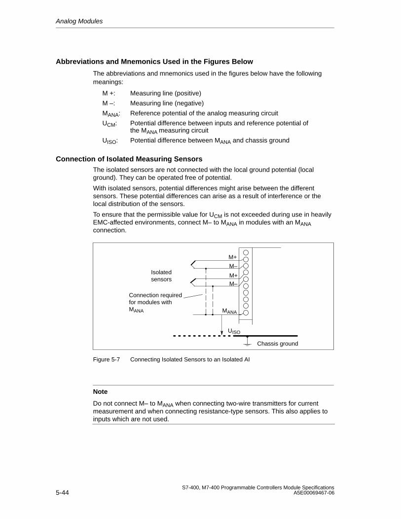
Analog Modules
5-44S7-400, M7-400 Programmable Controllers Module Specifications
A5E00069467-06
Abbreviations and Mnemonics Used in the Figures Below
The abbreviations and mnemonics used in the figures below have the followingmeanings:
M +: Measuring line (positive)
M –: Measuring line (negative)
MANA: Reference potential of the analog measuring circuit
UCM: Potential difference between inputs and reference potential of the MANA measuring circuit
UISO: Potential difference between MANA and chassis ground
Connection of Isolated Measuring SensorsThe isolated sensors are not connected with the local ground potential (localground). They can be operated free of potential.
With isolated sensors, potential differences might arise between the differentsensors. These potential differences can arise as a result of interference or thelocal distribution of the sensors.
To ensure that the permissible value for UCM is not exceeded during use in heavilyEMC-affected environments, connect M– to MANA in modules with an MANAconnection.
M+
M–
UISO
M+M–
MANA
Connection requiredfor modules withMANA
Chassis ground
Isolated sensors
Figure 5-7 Connecting Isolated Sensors to an Isolated AI
Note
Do not connect M– to MANA when connecting two-wire transmitters for currentmeasurement and when connecting resistance-type sensors. This also applies toinputs which are not used.
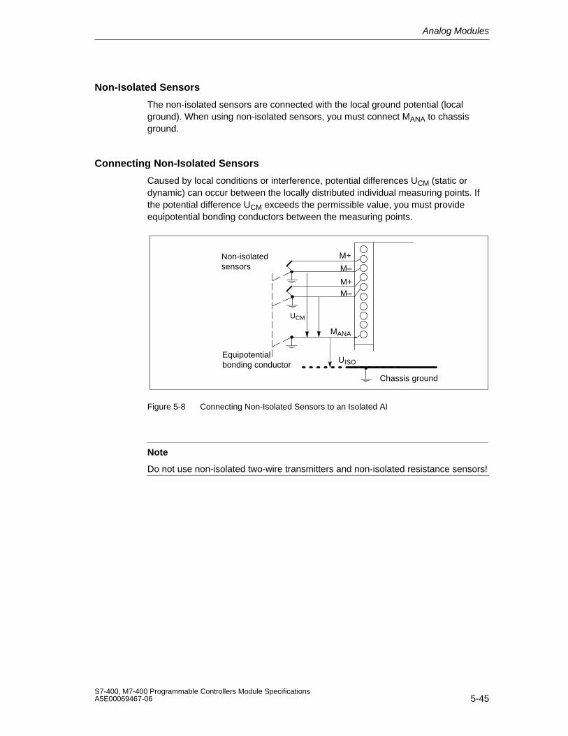
Analog Modules
5-45S7-400, M7-400 Programmable Controllers Module SpecificationsA5E00069467-06
Non-Isolated Sensors
The non-isolated sensors are connected with the local ground potential (localground). When using non-isolated sensors, you must connect MANA to chassisground.
Connecting Non-Isolated Sensors
Caused by local conditions or interference, potential differences UCM (static ordynamic) can occur between the locally distributed individual measuring points. Ifthe potential difference UCM exceeds the permissible value, you must provideequipotential bonding conductors between the measuring points.
M+
M–
UISO
M+M–
MANA
Chassis ground
Non-isolatedsensors
UCM
Equipotentialbonding conductor
Figure 5-8 Connecting Non-Isolated Sensors to an Isolated AI
Note
Do not use non-isolated two-wire transmitters and non-isolated resistance sensors!
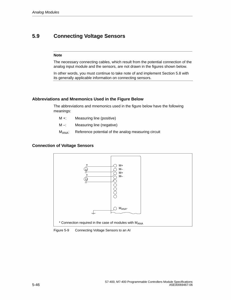
Analog Modules
5-46S7-400, M7-400 Programmable Controllers Module Specifications
A5E00069467-06
5.9 Connecting Voltage Sensors
Note
The necessary connecting cables, which result from the potential connection of theanalog input module and the sensors, are not drawn in the figures shown below.
In other words, you must continue to take note of and implement Section 5.8 withits generally applicable information on connecting sensors.
Abbreviations and Mnemonics Used in the Figure Below
The abbreviations and mnemonics used in the figure below have the followingmeanings:
M +: Measuring line (positive)
M –: Measuring line (negative)
MANA: Reference potential of the analog measuring circuit
Connection of Voltage Sensors
+
–U
+
–U
M+M–M+
MANA*
M–
* Connection required in the case of modules with MANA
Figure 5-9 Connecting Voltage Sensors to an AI
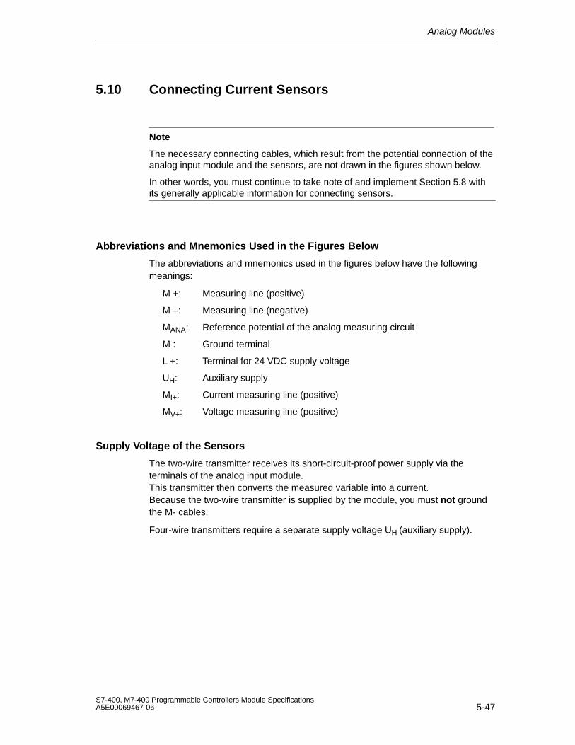
Analog Modules
5-47S7-400, M7-400 Programmable Controllers Module SpecificationsA5E00069467-06
5.10 Connecting Current Sensors
Note
The necessary connecting cables, which result from the potential connection of theanalog input module and the sensors, are not drawn in the figures shown below.
In other words, you must continue to take note of and implement Section 5.8 withits generally applicable information for connecting sensors.
Abbreviations and Mnemonics Used in the Figures Below
The abbreviations and mnemonics used in the figures below have the followingmeanings:
M +: Measuring line (positive)
M –: Measuring line (negative)
MANA: Reference potential of the analog measuring circuit
M : Ground terminal
L +: Terminal for 24 VDC supply voltage
UH: Auxiliary supply
MI+: Current measuring line (positive)
MV+: Voltage measuring line (positive)
Supply Voltage of the Sensors
The two-wire transmitter receives its short-circuit-proof power supply via theterminals of the analog input module. This transmitter then converts the measured variable into a current. Because the two-wire transmitter is supplied by the module, you must not groundthe M- cables.
Four-wire transmitters require a separate supply voltage UH (auxiliary supply).
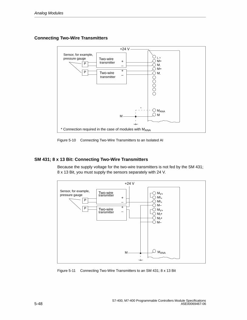
Analog Modules
5-48S7-400, M7-400 Programmable Controllers Module Specifications
A5E00069467-06
Connecting Two-Wire Transmitters
+24 V
Sensor, for example,pressure gauge
+–
L +M+M-M+M-
M
Two-wiretransmitter
Two-wiretransmitter
+–
M
P
P
MANA
* Connection required in the case of modules with MANA
*
Figure 5-10 Connecting Two-Wire Transmitters to an Isolated AI
SM 431; 8 x 13 Bit: Connecting Two-Wire Transmitters
Because the supply voltage for the two-wire transmitters is not fed by the SM 431;8 x 13 Bit, you must supply the sensors separately with 24 V.
+24 V
Sensor, for example,pressure gauge
+– MI+
M–Two-wiretransmitter
Two-wiretransmitter
+–
MANA
MV+
MV+MI+
M–MI+
MI+
M
P
P
Figure 5-11 Connecting Two-Wire Transmitters to an SM 431; 8 x 13 Bit
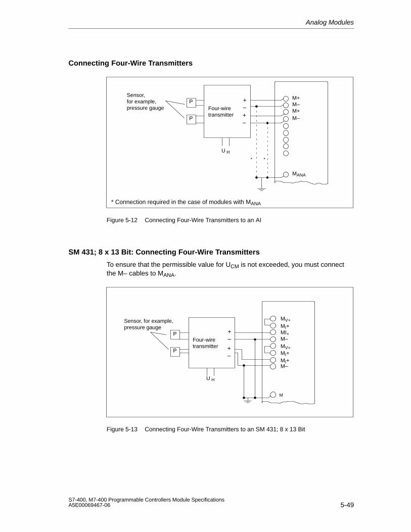
Analog Modules
5-49S7-400, M7-400 Programmable Controllers Module SpecificationsA5E00069467-06
Connecting Four-Wire Transmitters
M+M–M+M–
MANA
Sensor, for example,pressure gauge
+–Four-wire
transmitter +–
U H
* Connection required in the case of modules with MANA
P
P
**
Figure 5-12 Connecting Four-Wire Transmitters to an AI
SM 431; 8 x 13 Bit: Connecting Four-Wire Transmitters
To ensure that the permissible value for UCM is not exceeded, you must connectthe M– cables to MANA.
M
Sensor, for example,pressure gauge
+–Four-wire
transmitter +–
U H
MI+MI+M–
MV+
MV+MI+MI+M–
P
P
Figure 5-13 Connecting Four-Wire Transmitters to an SM 431; 8 x 13 Bit

Analog Modules
5-50S7-400, M7-400 Programmable Controllers Module Specifications
A5E00069467-06
5.11 Connecting Resistance Thermometers and Resistors
Note
The necessary connecting cables, which result from the potential connection of theanalog input module and the sensors, are not drawn in the figures shown below.
In other words, you must continue to take note of and implement Section 5.8 withits generally applicable information for connecting sensors.
Abbreviations and Mnemonics Used in the Figures Below
The abbreviations and mnemonics used in the figures below have the followingmeanings:
IC+: Constant-current lead (positive)
IC–: Constant-current lead (negative)
M+: Measuring line (positive)
M–: Measuring line (negative)
Connecting Resistance Thermometers and Resistors
The resistance thermometers/resistors are wired in a four-conductor,three-conductor or two-conductor connection.
With four-conductor and three-conductor connections, the module supplies aconstant current via terminals IC + and IC – so that the potential drop occurring onthe measuring cables is compensated. It is important that the connected constantcurrent cables are directly connected to the resistance thermometer/resistor.
Measurements with four-conductor or three-conductor connections supply a moreprecise measuring result due to compensation than measurements with atwo-conductor connection.
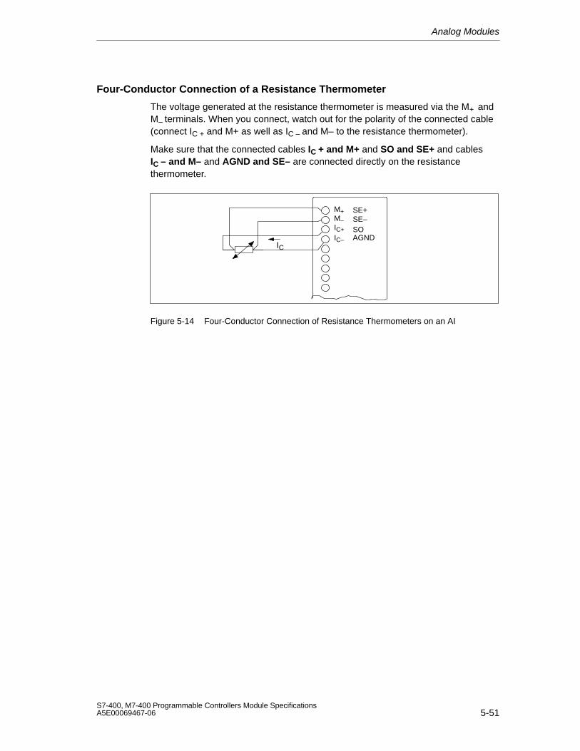
Analog Modules
5-51S7-400, M7-400 Programmable Controllers Module SpecificationsA5E00069467-06
Four-Conductor Connection of a Resistance Thermometer
The voltage generated at the resistance thermometer is measured via the M+ andM– terminals. When you connect, watch out for the polarity of the connected cable(connect IC + and M+ as well as IC – and M– to the resistance thermometer).
Make sure that the connected cables IC + and M+ and SO and SE+ and cablesIC – and M– and AGND and SE– are connected directly on the resistancethermometer.
IC
M+M–IC+IC–
SE+SE–SOAGND
Figure 5-14 Four-Conductor Connection of Resistance Thermometers on an AI
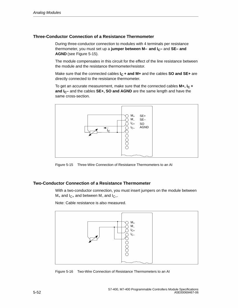
Analog Modules
5-52S7-400, M7-400 Programmable Controllers Module Specifications
A5E00069467-06
Three-Conductor Connection of a Resistance Thermometer
During three-conductor connection to modules with 4 terminals per resistancethermometer, you must set up a jumper between M– and IC– and SE– andAGND (see Figure 5-15).
The module compensates in this circuit for the effect of the line resistance betweenthe module and the resistance thermometer/resistor.
Make sure that the connected cables IC + and M+ and the cables SO and SE+ aredirectly connected to the resistance thermometer.
To get an accurate measurement, make sure that the connected cables M+, IC +and IC– and the cables SE+, SO and AGND are the same length and have thesame cross-section.
IC
M+M–IC+IC–
SE+SE–SOAGND
Figure 5-15 Three-Wire Connection of Resistance Thermometers to an AI
Two-Conductor Connection of a Resistance Thermometer
With a two-conductor connection, you must insert jumpers on the module betweenM+ and IC+ and between M– and IC–.
Note: Cable resistance is also measured.
M+M–IC+IC–
Figure 5-16 Two-Wire Connection of Resistance Thermometers to an AI
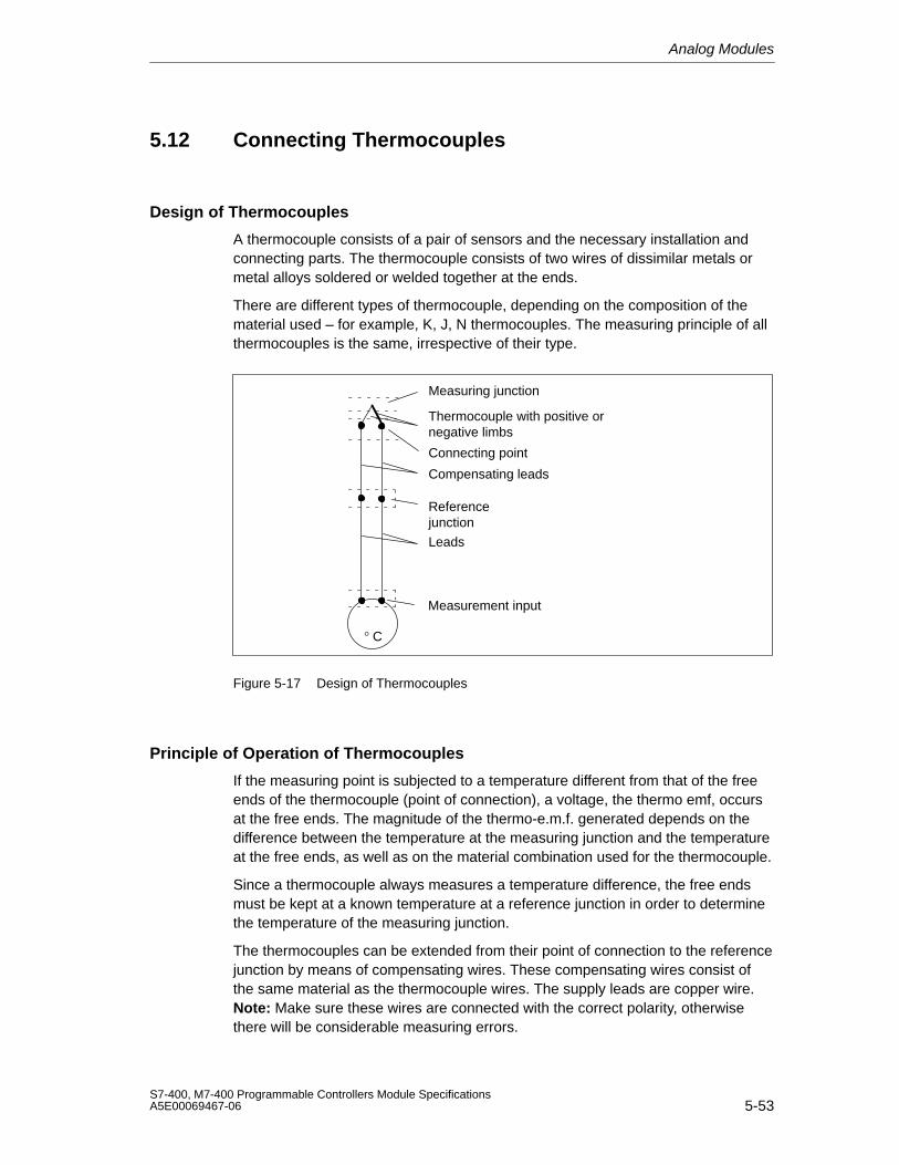
Analog Modules
5-53S7-400, M7-400 Programmable Controllers Module SpecificationsA5E00069467-06
5.12 Connecting Thermocouples
Design of Thermocouples
A thermocouple consists of a pair of sensors and the necessary installation andconnecting parts. The thermocouple consists of two wires of dissimilar metals ormetal alloys soldered or welded together at the ends.
There are different types of thermocouple, depending on the composition of thematerial used – for example, K, J, N thermocouples. The measuring principle of allthermocouples is the same, irrespective of their type.
° C
Leads
Compensating leads
Referencejunction
Connecting point
Thermocouple with positive ornegative limbs
Measuring junction
Measurement input
Figure 5-17 Design of Thermocouples
Principle of Operation of Thermocouples
If the measuring point is subjected to a temperature different from that of the freeends of the thermocouple (point of connection), a voltage, the thermo emf, occursat the free ends. The magnitude of the thermo-e.m.f. generated depends on thedifference between the temperature at the measuring junction and the temperatureat the free ends, as well as on the material combination used for the thermocouple.
Since a thermocouple always measures a temperature difference, the free endsmust be kept at a known temperature at a reference junction in order to determinethe temperature of the measuring junction.
The thermocouples can be extended from their point of connection to the referencejunction by means of compensating wires. These compensating wires consist ofthe same material as the thermocouple wires. The supply leads are copper wire.Note: Make sure these wires are connected with the correct polarity, otherwisethere will be considerable measuring errors.
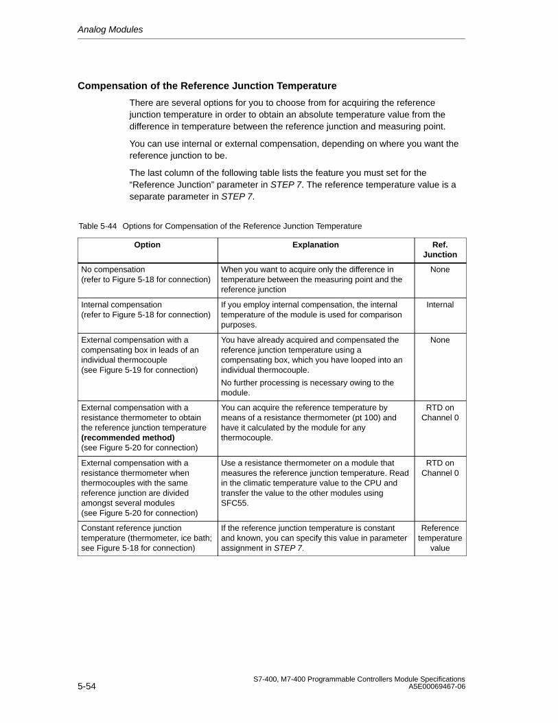
Analog Modules
5-54S7-400, M7-400 Programmable Controllers Module Specifications
A5E00069467-06
Compensation of the Reference Junction Temperature
There are several options for you to choose from for acquiring the referencejunction temperature in order to obtain an absolute temperature value from thedifference in temperature between the reference junction and measuring point.
You can use internal or external compensation, depending on where you want thereference junction to be.
The last column of the following table lists the feature you must set for the“Reference Junction” parameter in STEP 7. The reference temperature value is aseparate parameter in STEP 7.
Table 5-44 Options for Compensation of the Reference Junction Temperature
Option Explanation Ref.Junction
No compensation(refer to Figure 5-18 for connection)
When you want to acquire only the difference intemperature between the measuring point and thereference junction
None
Internal compensation(refer to Figure 5-18 for connection)
If you employ internal compensation, the internaltemperature of the module is used for comparisonpurposes.
Internal
External compensation with acompensating box in leads of anindividual thermocouple(see Figure 5-19 for connection)
You have already acquired and compensated thereference junction temperature using acompensating box, which you have looped into anindividual thermocouple.
No further processing is necessary owing to themodule.
None
External compensation with aresistance thermometer to obtainthe reference junction temperature(recommended method)(see Figure 5-20 for connection)
You can acquire the reference temperature bymeans of a resistance thermometer (pt 100) andhave it calculated by the module for anythermocouple.
RTD onChannel 0
External compensation with aresistance thermometer whenthermocouples with the samereference junction are dividedamongst several modules(see Figure 5-20 for connection)
Use a resistance thermometer on a module thatmeasures the reference junction temperature. Readin the climatic temperature value to the CPU andtransfer the value to the other modules usingSFC55.
RTD onChannel 0
Constant reference junctiontemperature (thermometer, ice bath;see Figure 5-18 for connection)
If the reference junction temperature is constantand known, you can specify this value in parameterassignment in STEP 7.
Referencetemperature
value
Analog Modules
5-55S7-400, M7-400 Programmable Controllers Module SpecificationsA5E00069467-06
Theory of Operation of Internal Compensation
With internal compensation, you can establish the reference point across theterminals of the analog input modules. In this case, you must run the compensatinglines right up to the analog module. The internal temperature sensor acquires thetemperature of the module and supplies a compensation voltage.
Note that internal compensation is not as accurate as external compensation.
Theory of Operation of External Compensation with Compensating Box
If you employ external compensation, the temperature of the reference junction ofthe thermocouples is taken into account via a compensating box, for example.
The compensating box contains a bridge circuit calibrated for a definite referencejunction temperature. The reference junction is formed by the connections for theends of the thermocouple’s compensating leads.
If the actual temperature deviates from the compensating temperature, thetemperature-sensitive bridge resistance changes. This results in a positive ornegative compensating voltage, which is added to the thermo-e.m.f.
Abbreviations and Mnemonics Used in the Figures Below
The abbreviations and mnemonics used in the figures below have the followingmeanings:
M +: Measuring line (positive)
M –: Measuring line (negative)
IC+: Constant-current lead (positive)
IC–: Constant-current lead (negative)
Note
The necessary connecting cables, which result from the potential connection of theanalog input module and the sensors, are not drawn in the figures shown below.
In other words, you must continue to take note of and implement Section 5.8 withits generally applicable information for connecting sensors.
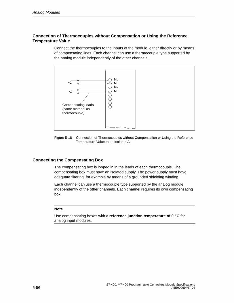
Analog Modules
5-56S7-400, M7-400 Programmable Controllers Module Specifications
A5E00069467-06
Connection of Thermocouples without Compensation or Using the ReferenceTemperature Value
Connect the thermocouples to the inputs of the module, either directly or by meansof compensating lines. Each channel can use a thermocouple type supported bythe analog module independently of the other channels.
M+M–M+M–
Compensating leads(same material asthermocouple)
Figure 5-18 Connection of Thermocouples without Compensation or Using the ReferenceTemperature Value to an Isolated AI
Connecting the Compensating Box
The compensating box is looped in in the leads of each thermocouple. Thecompensating box must have an isolated supply. The power supply must haveadequate filtering, for example by means of a grounded shielding winding.
Each channel can use a thermocouple type supported by the analog moduleindependently of the other channels. Each channel requires its own compensatingbox.
Note
Use compensating boxes with a reference junction temperature of 0 C foranalog input modules.
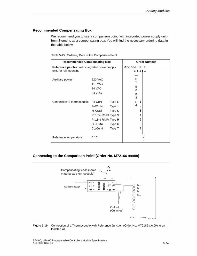
Analog Modules
5-57S7-400, M7-400 Programmable Controllers Module SpecificationsA5E00069467-06
Recommended Compensating Box
We recommend you to use a comparison point (with integrated power supply unit)from Siemens as a compensating box. You will find the necessary ordering data inthe table below.
Table 5-45 Ordering Data of the Comparison Point
Recommended Compensating Box Order Number
Reference junction with integrated power supplyunit, for rail mounting
Auxiliary power 220 VAC
110 VAC
24 VAC
24 VDC
Connection to thermocouple Fe-CuNi Type L
Fe/Cu Ni Type J
Ni Cr/Ni Type K
Pt 10% Rh/Pt Type S
Pt 13% Rh/Pt Type R
Cu-CuNi Type U
Cu/Cu Ni Type T
Reference temperature 0C
M72166-
B1
B2
B3
B4
1
2
3
4
5
6
7
00
Connecting to the Comparison Point (Order No. M72166-xxx00)
Output (Cu wires)
M+M–M+M–
Compensating leads (samematerial as thermocouple)
+
– –
+
–
Auxiliary power
+
Figure 5-19 Connection of a Thermocouple with Reference Junction (Order No. M72166-xxx00) to anIsolated AI
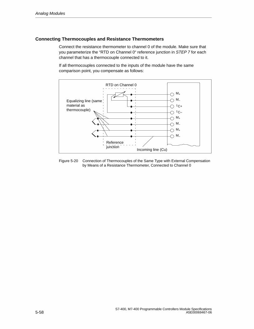
Analog Modules
5-58S7-400, M7-400 Programmable Controllers Module Specifications
A5E00069467-06
Connecting Thermocouples and Resistance Thermometers
Connect the resistance thermometer to channel 0 of the module. Make sure thatyou parameterize the “RTD on Channel 0“ reference junction in STEP 7 for eachchannel that has a thermocouple connected to it.
If all thermocouples connected to the inputs of the module have the samecomparison point, you compensate as follows:
M+
M–
M+
M–
Referencejunction
Incoming line (Cu)
Equalizing line (samematerial asthermocouple)
M–
I
I
C+
C–
M+
RTD on Channel 0
Figure 5-20 Connection of Thermocouples of the Same Type with External Compensationby Means of a Resistance Thermometer, Connected to Channel 0
Analog Modules
5-59S7-400, M7-400 Programmable Controllers Module SpecificationsA5E00069467-06
5.13 Connecting Loads/Actuators to Analog Outputs
Introduction
You can use the analog output modules to supply loads and actuators with currentand voltage.
This section contains general information that is generally applicable to all theconnection options for loads and actuators described in the sections that follow.
Cables for Analog Signals
For the analog signals, you should use shielded and twisted pair cables. The cablesQV and S+ and M and S–, respectively, are to be twisted together. This reduces theinterference. Ground the screen of the analog cables at both ends of the cables.
If there are potential differences between the cable ends, an equipotential bonding current, which can flow over the shield, can cause interference of theanalog signals. In such a case, you should ground the shield at one end of thecable only.
Isolated Analog Output Modules
With the isolated analog output modules there is no electrical connection betweenthe reference point of the measuring circuit MANA and chassis ground.
You must use isolated analog output modules if a potential difference UISO canoccur between the reference point of the measuring circuit MANA and chassisground. By means of an equipotential bonding conductor between the MANAterminal and chassis ground, make sure that UISO does not exceed the permittedvalue.
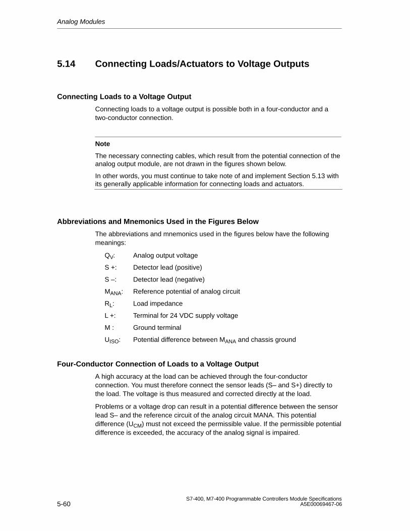
Analog Modules
5-60S7-400, M7-400 Programmable Controllers Module Specifications
A5E00069467-06
5.14 Connecting Loads/Actuators to Voltage Outputs
Connecting Loads to a Voltage Output
Connecting loads to a voltage output is possible both in a four-conductor and atwo-conductor connection.
Note
The necessary connecting cables, which result from the potential connection of theanalog output module, are not drawn in the figures shown below.
In other words, you must continue to take note of and implement Section 5.13 withits generally applicable information for connecting loads and actuators.
Abbreviations and Mnemonics Used in the Figures Below
The abbreviations and mnemonics used in the figures below have the followingmeanings:
QV: Analog output voltage
S +: Detector lead (positive)
S –: Detector lead (negative)
MANA: Reference potential of analog circuit
RL: Load impedance
L +: Terminal for 24 VDC supply voltage
M : Ground terminal
UISO: Potential difference between MANA and chassis ground
Four-Conductor Connection of Loads to a Voltage Output
A high accuracy at the load can be achieved through the four-conductorconnection. You must therefore connect the sensor leads (S– and S+) directly tothe load. The voltage is thus measured and corrected directly at the load.
Problems or a voltage drop can result in a potential difference between the sensorlead S– and the reference circuit of the analog circuit MANA. This potentialdifference (UCM) must not exceed the permissible value. If the permissible potentialdifference is exceeded, the accuracy of the analog signal is impaired.
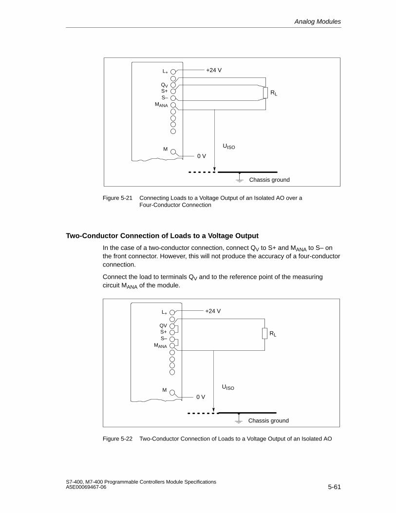
Analog Modules
5-61S7-400, M7-400 Programmable Controllers Module SpecificationsA5E00069467-06
+24 VL+
QVS+S–
MANA
0 VM
UISO
Chassis ground
RL
Figure 5-21 Connecting Loads to a Voltage Output of an Isolated AO over aFour-Conductor Connection
Two-Conductor Connection of Loads to a Voltage Output
In the case of a two-conductor connection, connect QV to S+ and MANA to S– onthe front connector. However, this will not produce the accuracy of a four-conductorconnection.
Connect the load to terminals QV and to the reference point of the measuringcircuit MANA of the module.
+24 VL+
QVS+S–
MANA
0 VM
UISO
Chassis ground
RL
Figure 5-22 Two-Conductor Connection of Loads to a Voltage Output of an Isolated AO
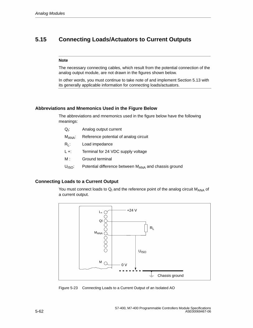
Analog Modules
5-62S7-400, M7-400 Programmable Controllers Module Specifications
A5E00069467-06
5.15 Connecting Loads/Actuators to Current Outputs
Note
The necessary connecting cables, which result from the potential connection of theanalog output module, are not drawn in the figures shown below.
In other words, you must continue to take note of and implement Section 5.13 withits generally applicable information for connecting loads/actuators.
Abbreviations and Mnemonics Used in the Figure Below
The abbreviations and mnemonics used in the figure below have the followingmeanings:
QI: Analog output current
MANA: Reference potential of analog circuit
RL: Load impedance
L +: Terminal for 24 VDC supply voltage
M : Ground terminal
UISO: Potential difference between MANA and chassis ground
Connecting Loads to a Current Output
You must connect loads to QI and the reference point of the analog circuit MANA ofa current output.
+24 V
RL
L+
QI
MANA
M0 V
UISO
Chassis ground
Figure 5-23 Connecting Loads to a Current Output of an Isolated AO
Analog Modules
5-63S7-400, M7-400 Programmable Controllers Module SpecificationsA5E00069467-06
5.16 Diagnostics of the Analog Modules
Programmable and Non-Programmable Diagnostic Messages
In diagnostics, we make a distinction between programmable andnon-programmable diagnostic messages.
You obtain programmable diagnostic messages only if you have enableddiagnostics by parameter assignment. You perform parameter assignment in the“Diagnostics” parameter block in STEP 7 (refer to Section 5.7).
Non-programmable diagnostic messages are always made available by the analogmodule irrespective of diagnostics being enabled.
Actions Following Diagnostic Messages in STEP 7
Each diagnostic message leads to the following actions:
• The diagnostic message is entered in the diagnosis of the analog module,forwarded to the CPU and can be read out by the user program.
• The error LED on the analog module lights.
• If you have enabled diagnostic interrupts in STEP 7, a diagnostic interrupt istriggered and OB 82 is called (refer to Section 4.5).
Reading out Diagnostic Messages
You can read out detailed diagnostic messages by means of SFCs in the userprogram (refer to the Appendix “Diagnostic Data of Signal Modules”).
You can view the cause of the error in STEP 7 in the module diagnosis (refer to the STEP 7 online help system).
Diagnostic Message in the Measured Value of Analog Input Modules
Every analog input module supplies the measured value 7FFFH irrespective of theparameter assignment when an error is detected. This measured value meanseither Overflow, Malfunction or a channel is disabled.
Diagnostic Message via the INTF and EXTF LEDs
Some analog input modules indicate faults by means of their two fault LEDs INTF(internal fault) and EXTF (external fault). The LEDs go out when all the internal andexternal faults have been eliminated.
Refer to the technical specifications of the modules, starting at Section 5.18, to findout which analog input modules have these fault LEDs.
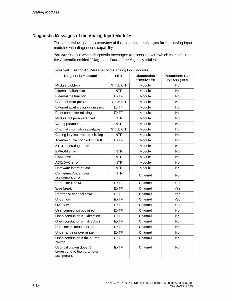
Analog Modules
5-64S7-400, M7-400 Programmable Controllers Module Specifications
A5E00069467-06
Diagnostic Messages of the Analog Input Modules
The table below gives an overview of the diagnostic messages for the analog inputmodules with diagnostics capability.
You can find out which diagnostic messages are possible with which modules inthe Appendix entitled “Diagnostic Data of the Signal Modules”.
Table 5-46 Diagnostic Messages of the Analog Input Modules
Diagnostic Message LED DiagnosticsEffective for
Parameters CanBe Assigned
Module problem INTF/EXTF Module No
Internal malfunction INTF Module No
External malfunction EXTF Module No
Channel error present INTF/EXTF Module No
External auxiliary supply missing EXTF Module No
Front connector missing EXTF Module No
Module not parameterized. INTF Module No
Wrong parameters INTF Module No
Channel information available INTF/EXTF Module No
Coding key incorrect or missing INTF Module No
Thermocouple connection fault EXTF Module No
STOP operating mode – Module No
EPROM error INTF Module No
RAM error INTF Module No
ADC/DAC error INTF Module No
Hardware interrupt lost INTF Module No
Configuring/parameterassignment error
INTFChannel No
Short-circuit to M EXTF Channel Yes
Wire break EXTF Channel Yes
Reference channel error EXTF Channel Yes
Underflow EXTF Channel Yes
Overflow EXTF Channel Yes
User connection not wired EXTF Channel No
Open conductor in + direction EXTF Channel No
Open conductor in – direction EXTF Channel No
Run time calibration error EXTF Channel No
Underrange or overrange EXTF Channel No
Open conductor in the currentsource
EXTF Channel No
User calibration doesn’tcorrespond to the parameterassignment
EXTF Channel No

Analog Modules
5-65S7-400, M7-400 Programmable Controllers Module SpecificationsA5E00069467-06
Note
A prerequisite for detecting the errors indicated by programmable diagnosticmessages is that you must have assigned parameters to the analog moduleaccordingly in STEP 7.
Causes of Errors and Remedial Measures for Analog Input Modules
Table 5-47 Diagnostics Messages of the Analog Input Modules, Causes of Errors and RemedialMeasures
DiagnosticsMessage
Possible Error Cause Remedy
Module malfunction An error detected by the modulehas occurred
-
Internal malfunction The module has detected an errorwithin the programmable controller
-
External malfunction The module has detected an erroroutside the programmable controller
-
There is a channelerror
Indicates that only certain channelsare faulty
-
No external auxiliaryvoltage
Load voltage to supply the 2-wiretransmitter is missing on terminalsL+ and M
Feed supply L+
No front connector Jumper between connections 1 and2 in the front connector missing
Install jumper
Parameters have notbeen assigned to themodule
The module requires the informationas to whether it should work withsystem default parameters or withyour parameters
Message queued after power-on untilparameter transmission by the CPU hasbeen completed; parameterize themodule, as required
Wrong parameters A parameter or combination ofparameters is incorrect;impermissible measurement range,for example
Reassign module parameter
Channel informationavailable
Channel error present; the modulecan supply additional channelinformation
-
Measuring rangemoduleincorrect/missing
One or more measuring rangemodules is missing or incorrectlyinserted
Insert the measuring range modules on themodule according to the parameterassignment of the type of measurementand the measurement range
STOP operating mode Module not parameterized and thefirst module cycle not completed
If a reboot of the CPU all the digitizedanalog values are in the intermediatememory, this message is reset
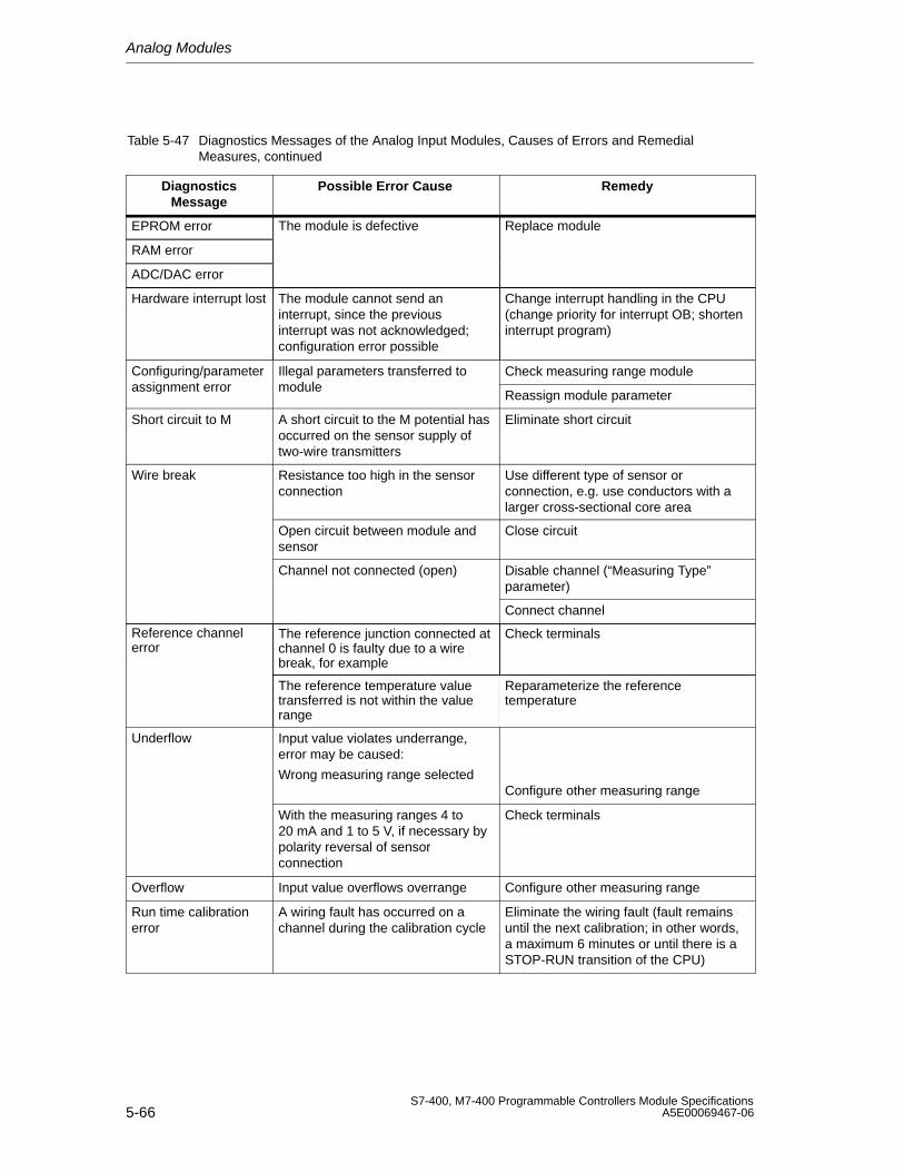
Analog Modules
5-66S7-400, M7-400 Programmable Controllers Module Specifications
A5E00069467-06
Table 5-47 Diagnostics Messages of the Analog Input Modules, Causes of Errors and RemedialMeasures, continued
DiagnosticsMessage
RemedyPossible Error Cause
EPROM error The module is defective Replace module
RAM error
ADC/DAC error
Hardware interrupt lost The module cannot send aninterrupt, since the previousinterrupt was not acknowledged;configuration error possible
Change interrupt handling in the CPU(change priority for interrupt OB; shorteninterrupt program)
Configuring/parameter Illegal parameters transferred to Check measuring range moduleassignment error module
Reassign module parameter
Short circuit to M A short circuit to the M potential hasoccurred on the sensor supply oftwo-wire transmitters
Eliminate short circuit
Wire break Resistance too high in the sensorconnection
Use different type of sensor orconnection, e.g. use conductors with alarger cross-sectional core area
Open circuit between module andsensor
Close circuit
Channel not connected (open) Disable channel (“Measuring Type”parameter)
Connect channel
Reference channelerror
The reference junction connected atchannel 0 is faulty due to a wirebreak, for example
Check terminals
The reference temperature valuetransferred is not within the valuerange
Reparameterize the referencetemperature
Underflow Input value violates underrange,error may be caused:
Wrong measuring range selectedConfigure other measuring range
With the measuring ranges 4 to20 mA and 1 to 5 V, if necessary bypolarity reversal of sensorconnection
Check terminals
Overflow Input value overflows overrange Configure other measuring range
Run time calibrationerror
A wiring fault has occurred on achannel during the calibration cycle
Eliminate the wiring fault (fault remainsuntil the next calibration; in other words,a maximum 6 minutes or until there is aSTOP-RUN transition of the CPU)
Analog Modules
5-67S7-400, M7-400 Programmable Controllers Module SpecificationsA5E00069467-06
5.17 Analog Module Interrupts
Introduction
In this Section, the interrupt behavior of the analog modules is described. Thefollowing interrupts exist:
• Diagnostic Interrupt
• Hardware interrupt
Note that not all analog modules have interrupt capability or they are only capableof a subset of the interrupts described here Refer to the technical specifications ofthe modules, starting at Section 5.18, to find out which analog modules haveinterrupt capability.
The OBs and SFCs mentioned below can be found in the online help system forSTEP 7, where they are described in greater detail.
Enabling Interrupts
The interrupts are not preset – in other words, they are inhibited withoutappropriate parameter assignment. You enable interrupts in STEP 7 (refer to Section 5.7).
Special Feature: The Module is Inserted in ER-1/ER-2
Note
If you use the analog module in ER-1/ER-2, you must set the parameters for theinput of all the interrupts to “No” because the interrupt lines are not available inER-1/ER-2.
Diagnostic Interrupt
If you have enabled diagnostic interrupts, then active error events (initialoccurrence of the error) and departing error events (message after troubleshooting)are reported by means of an interrupt.
The CPU interrupts the execution of the user program and processes thediagnostic interrupt block (OB 82).
In the user program, you can call SFC 51 or SFC 59 in OB 82 to obtain moredetailed diagnostic information from the module.
The diagnostic information is consistent until such time as OB 82 is exited. WhenOB 82 is exited, the diagnostic interrupt is acknowledged on the module.
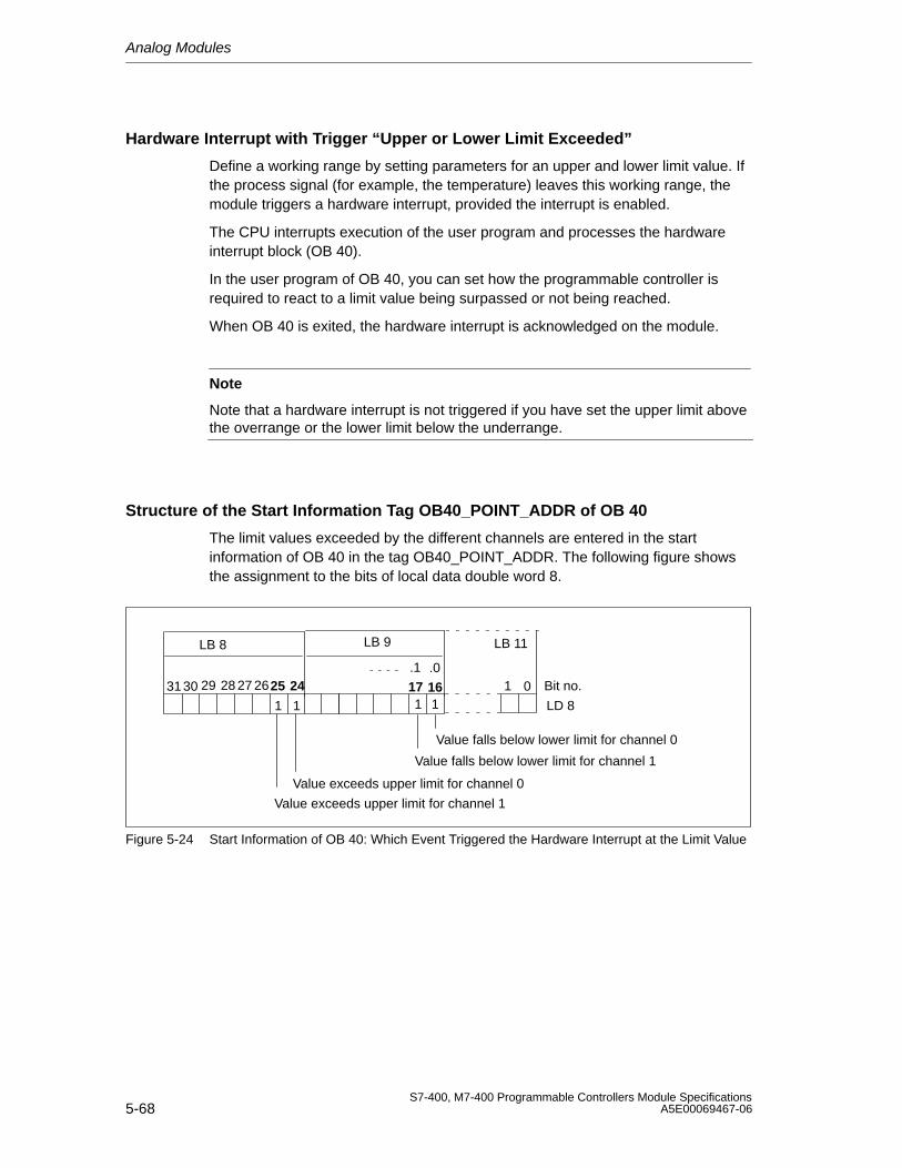
Analog Modules
5-68S7-400, M7-400 Programmable Controllers Module Specifications
A5E00069467-06
Hardware Interrupt with Trigger “Upper or Lower Limit Exceeded”
Define a working range by setting parameters for an upper and lower limit value. Ifthe process signal (for example, the temperature) leaves this working range, themodule triggers a hardware interrupt, provided the interrupt is enabled.
The CPU interrupts execution of the user program and processes the hardwareinterrupt block (OB 40).
In the user program of OB 40, you can set how the programmable controller isrequired to react to a limit value being surpassed or not being reached.
When OB 40 is exited, the hardware interrupt is acknowledged on the module.
Note
Note that a hardware interrupt is not triggered if you have set the upper limit abovethe overrange or the lower limit below the underrange.
Structure of the Start Information Tag OB40_POINT_ADDR of OB 40
The limit values exceeded by the different channels are entered in the startinformation of OB 40 in the tag OB40_POINT_ADDR. The following figure showsthe assignment to the bits of local data double word 8.
116 Bit no.173130 29 28 27 26
LD 81
LB 8 LB 9
25 24
Value exceeds upper limit for channel 0
Value falls below lower limit for channel 0
Value exceeds upper limit for channel 1
LB 11
01
Value falls below lower limit for channel 1
1 1
.0.1
Figure 5-24 Start Information of OB 40: Which Event Triggered the Hardware Interrupt at the Limit Value
Analog Modules
5-69S7-400, M7-400 Programmable Controllers Module SpecificationsA5E00069467-06
Hardware Interrupt on Trigger “Reached End of Scan Cycle”
By parameterizing the hardware interrupt a the end of the scan cycle, you have theoption of synchronizing a process with the scan cycle of the analog input module.
A scan cycle includes the conversion of the measured values of all enabledchannels of the analog input module. The module processes the channels oneafter the other. After all the measured values have been converted, the module ofthe CPU reports by means of an interrupt that there are new measured values onall channels.
You can use the interrupt to load the currently converted analog values.
Analog Modules
5-70S7-400, M7-400 Programmable Controllers Module Specifications
A5E00069467-06
5.18 Analog Input Module SM 431; AI 8 13 Bit;(6ES7431-1KF00-0AB0)
Characteristics
The analog input module SM 431; AI 8 13 Bit has the following features:
• 8 inputs for voltage/current measurement
• 4 inputs for resistance measurement
• Unlimited measuring range selection
• 13-bit resolution
• Analog section isolated from CPU
• The maximum permissible common mode voltage between the channels andbetween the reference potential of the connected sensors and MANA is 30 VAC
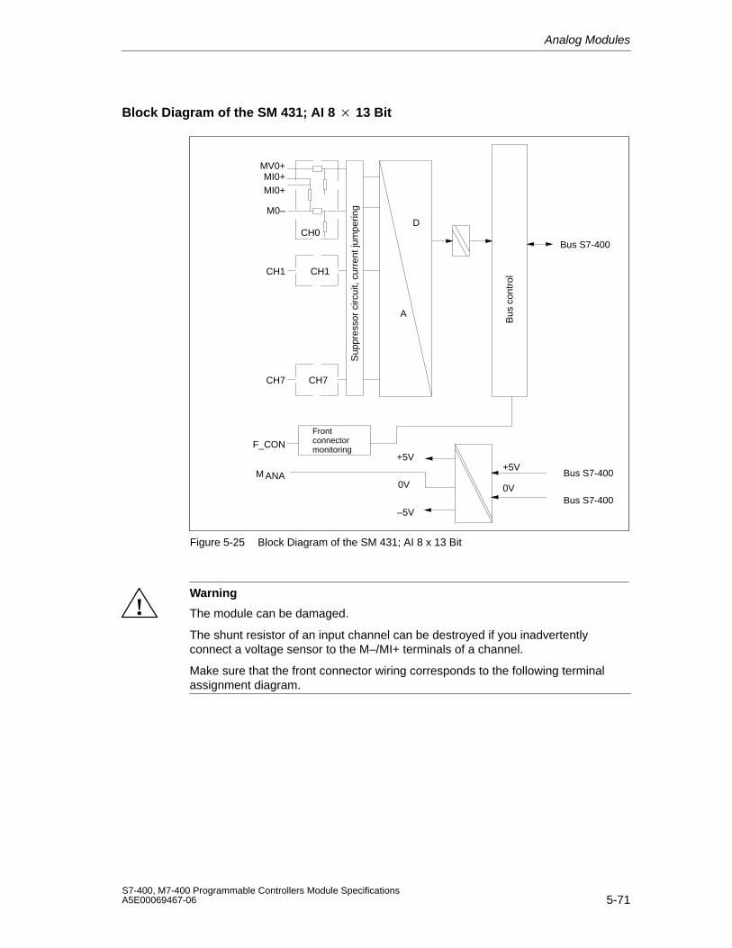
Analog Modules
5-71S7-400, M7-400 Programmable Controllers Module SpecificationsA5E00069467-06
Block Diagram of the SM 431; AI 8 13 Bit
A
D
+5V
0V
CH1
CH7
CH0
+5V
–5V
0V
Sup
pres
sor
circ
uit,
curr
ent j
umpe
ring
MV0+MI0+MI0+
M0–
CH1
CH7
F_CON
Bus
con
trol
M
Bus S7-400
ANA
Frontconnectormonitoring
Bus S7-400
Bus S7-400
Figure 5-25 Block Diagram of the SM 431; AI 8 x 13 Bit
!Warning
The module can be damaged.
The shunt resistor of an input channel can be destroyed if you inadvertentlyconnect a voltage sensor to the M–/MI+ terminals of a channel.
Make sure that the front connector wiring corresponds to the following terminalassignment diagram.
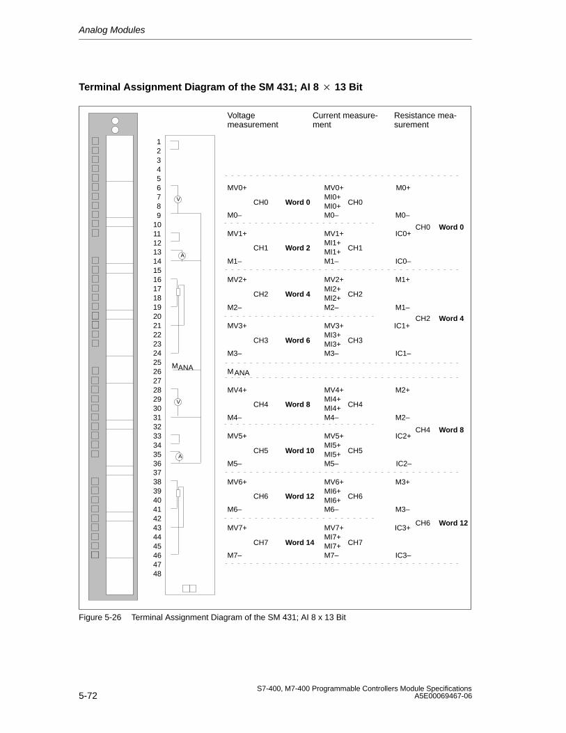
Analog Modules
5-72S7-400, M7-400 Programmable Controllers Module Specifications
A5E00069467-06
Terminal Assignment Diagram of the SM 431; AI 8 13 Bit
MANA
V
A
V
A
Voltage measurement
Current measure-ment
Resistance mea-surement
MV0+ MV0+ M0+
M0–
M1+
M1–
M2+
M2–
M3+
M3–
M0–
MV1+
M1–
MV2+
M2–
MV3+
M3–
M
MV4+
M4–
MV5+
M5–
MV6+
M6–
MV7+
M7–
MV7+MI7+MI7+M7–
MV6+MI6+MI6+M6–
MV5+MI5+MI5+M5–
MV4+MI4+MI4+M4–
MV3+MI3+MI3+M3–
MV2+MI2+MI2+M2–
MV1+MI1+MI1+M1–
MI0+MI0+M0–
IC0+
IC0–
IC1+
IC1–
IC2+
IC2–
IC3+
IC3–
CH0
CH1
CH2
CH3
CH4
CH5
CH6
CH7
CH0
CH1
CH2
CH3
CH4
CH5
CH6
CH7
CH0
CH2
CH4
CH6
ANA
293031323334353637
39404142434445464748
38
123456789
10111213141516171819202122232425262728
Word 0
Word 2
Word 4
Word 6
Word 8
Word 10
Word 12
Word 14
Word 0
Word 4
Word 8
Word 12
Figure 5-26 Terminal Assignment Diagram of the SM 431; AI 8 x 13 Bit
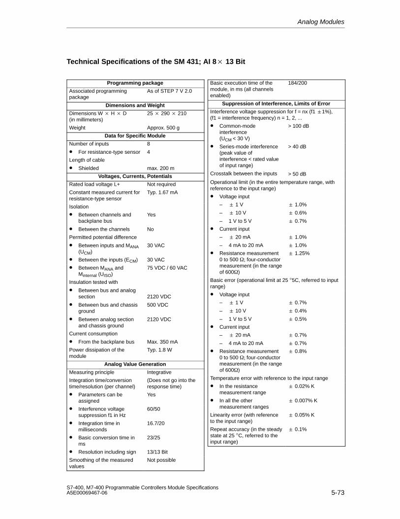
Analog Modules
5-73S7-400, M7-400 Programmable Controllers Module SpecificationsA5E00069467-06
Technical Specifications of the SM 431; AI 8 13 Bit
Programming package
Associated programmingpackage
As of STEP 7 V 2.0
Dimensions and Weight
Dimensions W H D(in millimeters)
25 290 210
Weight Approx. 500 g
Data for Specific Module
Number of inputs
• For resistance-type sensor
8
4
Length of cable
• Shielded max. 200 m
Voltages, Currents, Potentials
Rated load voltage L+ Not required
Constant measured current forresistance-type sensor
Typ. 1.67 mA
Isolation
• Between channels andbackplane bus
• Between the channels
Yes
No
Permitted potential difference
• Between inputs and MANA(UCM)
30 VAC
• Between the inputs (ECM) 30 VAC
• Between MANA andMinternal (UISO)
75 VDC / 60 VAC
Insulation tested with
• Between bus and analogsection
• Between bus and chassisground
• Between analog sectionand chassis ground
2120 VDC
500 VDC
2120 VDC
Current consumption
• From the backplane bus Max. 350 mA
Power dissipation of themodule
Typ. 1.8 W
Analog Value Generation
Measuring principle Integrative
Integration time/conversiontime/resolution (per channel)
(Does not go into theresponse time)
• Parameters can beassigned
Yes
• Interference voltagesuppression f1 in Hz
60/50
• Integration time inmilliseconds
16.7/20
• Basic conversion time inms
23/25
• Resolution including sign 13/13 Bit
Smoothing of the measuredvalues
Not possible
Basic execution time of themodule, in ms (all channelsenabled)
184/200
Suppression of Interference, Limits of Error
Interference voltage suppression for f = nx (f1 1%), (f1 = interference frequency) n = 1, 2, ...
• Common-modeinterference (UCM < 30 V)
> 100 dB
• Series-mode interference(peak value ofinterference < rated valueof input range)
> 40 dB
Crosstalk between the inputs > 50 dB
Operational limit (in the entire temperature range, withreference to the input range)
• Voltage input
– 1 V
– 10 V
– 1 V to 5 V
1.0%
0.6%
0.7%
• Current input
– 20 mA
– 4 mA to 20 mA
1.0%
1.0%
• Resistance measurement 0 to 500 fourconductormeasurement (in the rangeof 600)
1.25%
Basic error (operational limit at 25 °5C, referred to inputrange)
• Voltage input
– 1 V
– 10 V
– 1 V to 5 V
0.7%
0.4%
0.5%
• Current input
– 20 mA
– 4 mA to 20 mA
0.7%
0.7%
• Resistance measurement 0 to 500 fourconductormeasurement (in the rangeof 600)
0.8%
Temperature error with reference to the input range
• In the resistancemeasurement range
0.02% K
• In all the other measurement ranges
0.007% K
Linearity error (with referenceto the input range)
0.05% K
Repeat accuracy (in the steadystate at 25 °C, referred to theinput range)
0.1%
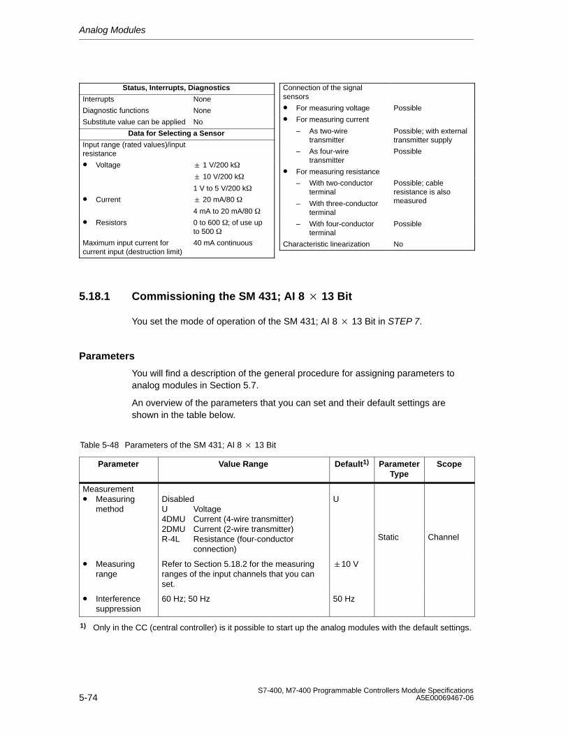
Analog Modules
5-74S7-400, M7-400 Programmable Controllers Module Specifications
A5E00069467-06
Status, Interrupts, Diagnostics
Interrupts None
Diagnostic functions None
Substitute value can be applied No
Data for Selecting a Sensor
Input range (rated values)/inputresistance
• Voltage 1 V/200 k
10 V/200 k
1 V to 5 V/200 k
• Current 20 mA/80
4 mA to 20 mA/80
• Resistors 0 to 600 ; of use upto 500
Maximum input current forcurrent input (destruction limit)
40 mA continuous
Connection of the signalsensors
• For measuring voltage Possible
• For measuring current
– As two-wiretransmitter
Possible; with externaltransmitter supply
– As four-wiretransmitter
Possible
• For measuring resistance
– With two-conductorterminal
– With three-conductorterminal
Possible; cableresistance is alsomeasured
– With four-conductorterminal
Possible
Characteristic linearization No
5.18.1 Commissioning the SM 431; AI 8 13 Bit
You set the mode of operation of the SM 431; AI 8 13 Bit in STEP 7.
Parameters
You will find a description of the general procedure for assigning parameters toanalog modules in Section 5.7.
An overview of the parameters that you can set and their default settings areshown in the table below.
Table 5-48 Parameters of the SM 431; AI 8 13 Bit
Parameter Value Range Default1) ParameterType
Scope
Measurement• Measuring
methodDisabledU Voltage4DMU Current (4-wire transmitter)2DMU Current (2-wire transmitter)R-4L Resistance (four-conductor
connection)
U
Static Channel
• Measuringrange
Refer to Section 5.18.2 for the measuringranges of the input channels that you canset.
10 V
• Interferencesuppression
60 Hz; 50 Hz 50 Hz
1) Only in the CC (central controller) is it possible to start up the analog modules with the default settings.
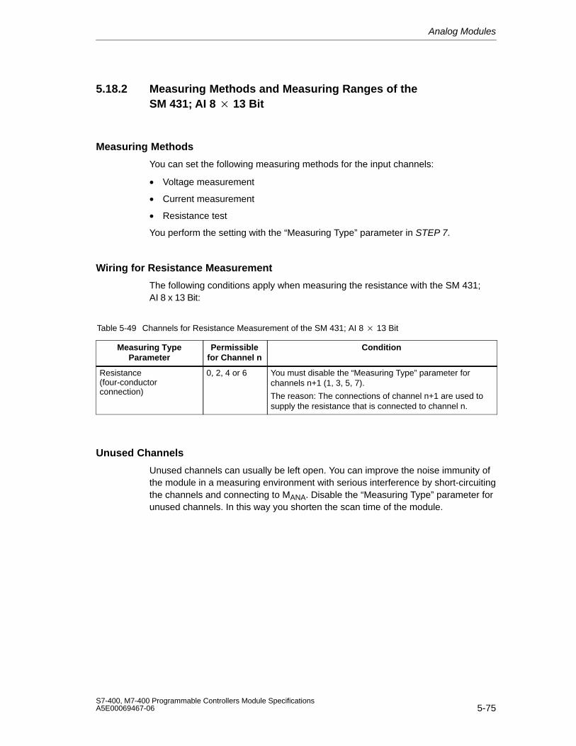
Analog Modules
5-75S7-400, M7-400 Programmable Controllers Module SpecificationsA5E00069467-06
5.18.2 Measuring Methods and Measuring Ranges of theSM 431; AI 8 13 Bit
Measuring Methods
You can set the following measuring methods for the input channels:
• Voltage measurement
• Current measurement
• Resistance test
You perform the setting with the “Measuring Type” parameter in STEP 7.
Wiring for Resistance Measurement
The following conditions apply when measuring the resistance with the SM 431;AI 8 x 13 Bit:
Table 5-49 Channels for Resistance Measurement of the SM 431; AI 8 13 Bit
Measuring TypeParameter
Permissiblefor Channel n
Condition
Resistance (four-conductorconnection)
0, 2, 4 or 6 You must disable the “Measuring Type” parameter forchannels n+1 (1, 3, 5, 7).
The reason: The connections of channel n+1 are used tosupply the resistance that is connected to channel n.
Unused Channels
Unused channels can usually be left open. You can improve the noise immunity ofthe module in a measuring environment with serious interference by short-circuitingthe channels and connecting to MANA. Disable the “Measuring Type” parameter forunused channels. In this way you shorten the scan time of the module.
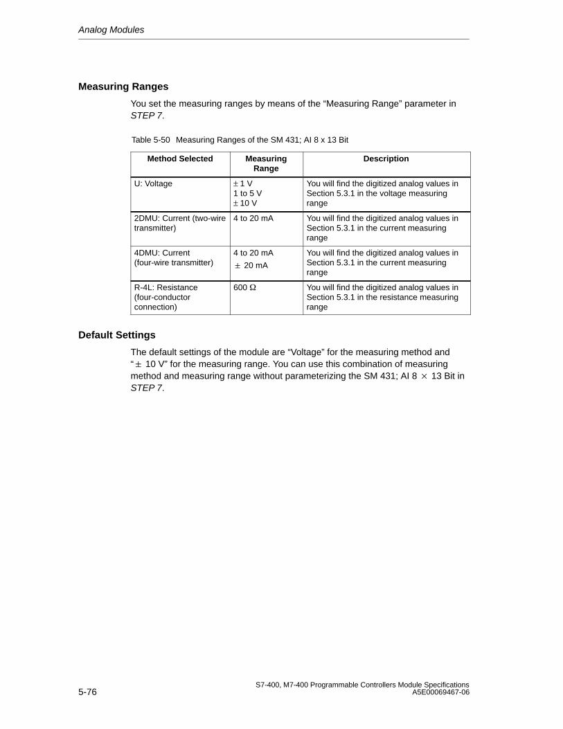
Analog Modules
5-76S7-400, M7-400 Programmable Controllers Module Specifications
A5E00069467-06
Measuring Ranges
You set the measuring ranges by means of the “Measuring Range” parameter inSTEP 7.
Table 5-50 Measuring Ranges of the SM 431; AI 8 x 13 Bit
Method Selected MeasuringRange
Description
U: Voltage ± 1 V1 to 5 V± 10 V
You will find the digitized analog values inSection 5.3.1 in the voltage measuringrange
2DMU: Current (two-wiretransmitter)
4 to 20 mA You will find the digitized analog values inSection 5.3.1 in the current measuringrange
4DMU: Current(four-wire transmitter)
4 to 20 mA
20 mA
You will find the digitized analog values inSection 5.3.1 in the current measuringrange
R-4L: Resistance(four-conductorconnection)
600 You will find the digitized analog values inSection 5.3.1 in the resistance measuringrange
Default Settings
The default settings of the module are “Voltage” for the measuring method and“ 10 V” for the measuring range. You can use this combination of measuringmethod and measuring range without parameterizing the SM 431; AI 8 13 Bit inSTEP 7.
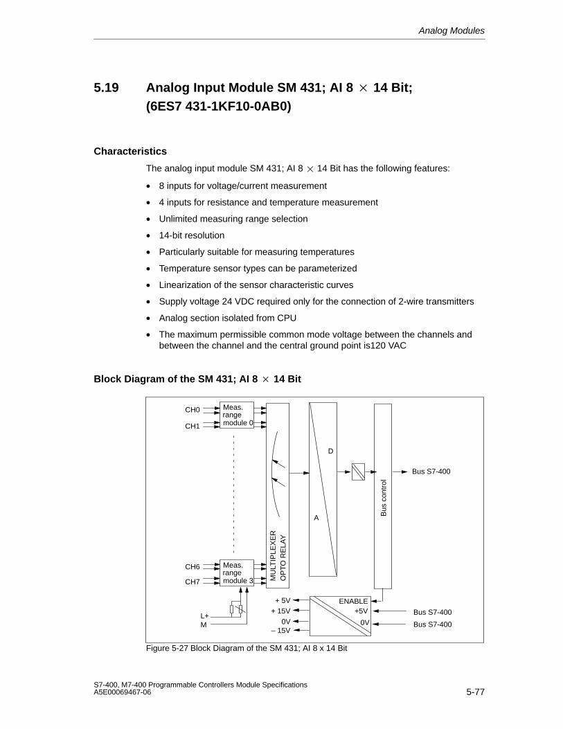
Analog Modules
5-77S7-400, M7-400 Programmable Controllers Module SpecificationsA5E00069467-06
5.19 Analog Input Module SM 431; AI 8 14 Bit;(6ES7 431-1KF10-0AB0)
Characteristics
The analog input module SM 431; AI 8 14 Bit has the following features:
• 8 inputs for voltage/current measurement
• 4 inputs for resistance and temperature measurement
• Unlimited measuring range selection
• 14-bit resolution
• Particularly suitable for measuring temperatures
• Temperature sensor types can be parameterized
• Linearization of the sensor characteristic curves
• Supply voltage 24 VDC required only for the connection of 2-wire transmitters
• Analog section isolated from CPU
• The maximum permissible common mode voltage between the channels andbetween the channel and the central ground point is120 VAC
Block Diagram of the SM 431; AI 8 14 Bit
CH0
CH1
CH6
CH7
+5V
0V0V – 15V
+ 5V + 15V
L+M
Bus S7-400
Bus
con
trol
ENABLE
MU
LTIP
LEX
ER
OP
TO
RE
LAY
A
D
Meas.rangemodule 0
Meas.rangemodule 3
Bus S7-400
Bus S7-400
Figure 5-27 Block Diagram of the SM 431; AI 8 x 14 Bit
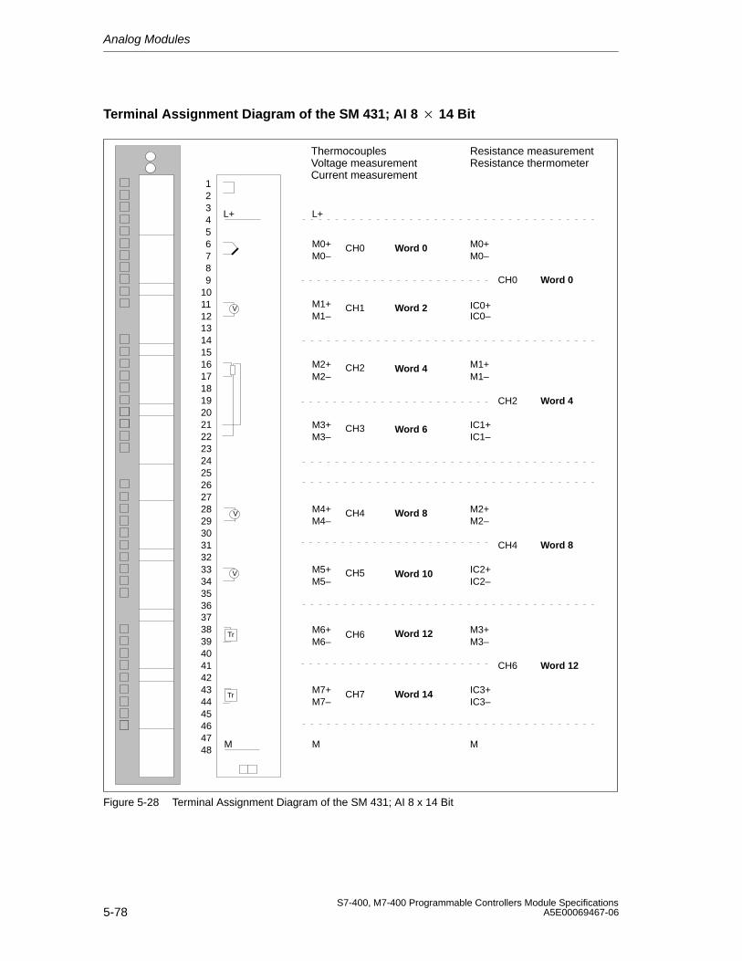
Analog Modules
5-78S7-400, M7-400 Programmable Controllers Module Specifications
A5E00069467-06
Terminal Assignment Diagram of the SM 431; AI 8 14 Bit
ThermocouplesVoltage measurementCurrent measurement
Resistance measurementResistance thermometer
M1+
M2–
M3–
M4–
M5–
M6–
M7–
CH0
CH1
CH2
CH3
CH4
CH5
CH6
CH7
L+
V
V
V
M
Tr
Tr
L+
M0+M0–
M1–
M2+
M3+
M4+
M5+
M6+
M7+
M
M0+M0–
IC0+IC0–
M1+M1–
IC1+IC1–
M2+M2–
IC2+IC2–
M3+M3–
IC3+IC3–
M
CH0
CH2
CH4
CH6
293031323334353637
39404142434445464748
38
123456789
10111213141516171819202122232425262728
Word 0
Word 2
Word 4
Word 6
Word 8
Word 10
Word 12
Word 14
Word 0
Word 4
Word 8
Word 12
Figure 5-28 Terminal Assignment Diagram of the SM 431; AI 8 x 14 Bit
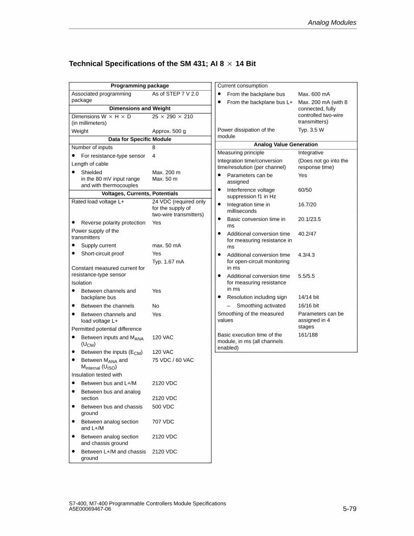
Analog Modules
5-79S7-400, M7-400 Programmable Controllers Module SpecificationsA5E00069467-06
Technical Specifications of the SM 431; AI 8 14 Bit
Programming package
Associated programmingpackage
As of STEP 7 V 2.0
Dimensions and Weight
Dimensions W H D(in millimeters)
25 290 210
Weight Approx. 500 g
Data for Specific Module
Number of inputs
• For resistance-type sensor
8
4
Length of cable
• Shielded in the 80 mV input rangeand with thermocouples
Max. 200 mMax. 50 m
Voltages, Currents, Potentials
Rated load voltage L+ 24 VDC (required onlyfor the supply oftwo-wire transmitters)
• Reverse polarity protection Yes
Power supply of thetransmitters
• Supply current max. 50 mA
• Short-circuit proof Yes
Constant measured current forresistance-type sensor
Typ. 1.67 mA
Isolation
• Between channels andbackplane bus
• Between the channels
• Between channels andload voltage L+
Yes
No
Yes
Permitted potential difference
• Between inputs and MANA(UCM)
120 VAC
• Between the inputs (ECM) 120 VAC
• Between MANA andMinternal (UISO)
75 VDC / 60 VAC
Insulation tested with
• Between bus and L+/M
• Between bus and analogsection
• Between bus and chassisground
• Between analog sectionand L+/M
• Between analog sectionand chassis ground
• Between L+/M and chassisground
2120 VDC
2120 VDC
500 VDC
707 VDC
2120 VDC
2120 VDC
Current consumption
• From the backplane bus Max. 600 mA
• From the backplane bus L+ Max. 200 mA (with 8connected, fullycontrolled two-wiretransmitters)
Power dissipation of themodule
Typ. 3.5 W
Analog Value Generation
Measuring principle Integrative
Integration time/conversiontime/resolution (per channel)
(Does not go into theresponse time)
• Parameters can beassigned
Yes
• Interference voltagesuppression f1 in Hz
60/50
• Integration time inmilliseconds
16.7/20
• Basic conversion time inms
20.1/23.5
• Additional conversion timefor measuring resistance inms
40.2/47
• Additional conversion timefor open-circuit monitoringin ms
4.3/4.3
• Additional conversion timefor measuring resistancein ms
5.5/5.5
• Resolution including sign
– Smoothing activated
14/14 bit
16/16 bit
Smoothing of the measuredvalues
Parameters can beassigned in 4 stages
Basic execution time of themodule, in ms (all channelsenabled)
161/188
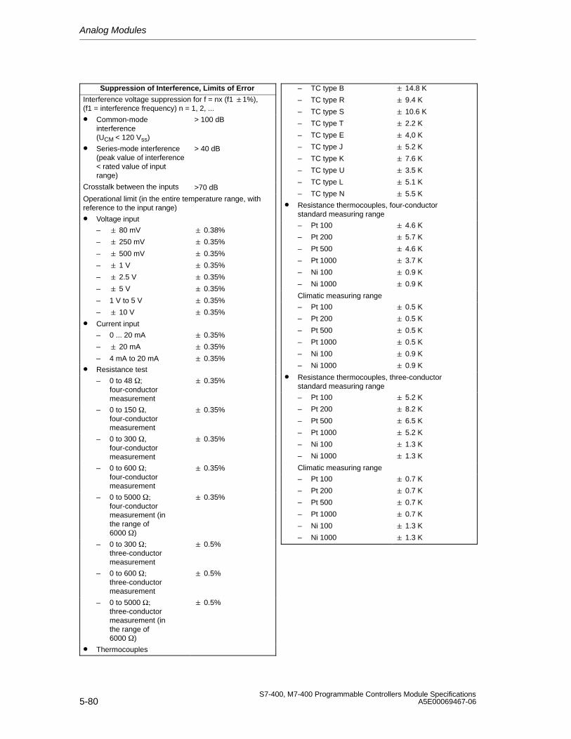
Analog Modules
5-80S7-400, M7-400 Programmable Controllers Module Specifications
A5E00069467-06
Suppression of Interference, Limits of Error
Interference voltage suppression for f = nx (f1 1%), (f1 = interference frequency) n = 1, 2, ...
• Common-modeinterference (UCM < 120 Vss)
> 100 dB
• Series-mode interference(peak value of interference < rated value of inputrange)
> 40 dB
Crosstalk between the inputs >70 dB
Operational limit (in the entire temperature range, withreference to the input range)
• Voltage input
– 80 mV
– 250 mV
– 500 mV
– 1 V
– 2.5 V
– 5 V
– 1 V to 5 V
– 10 V
0.38%
0.35%
0.35%
0.35%
0.35%
0.35%
0.35%
0.35%
• Current input
– 0 ... 20 mA
– 20 mA
– 4 mA to 20 mA
0.35%
0.35%
0.35%
• Resistance test
– 0 to 48 ;four-conductormeasurement
0.35%
– 0 to 150 , four-conductormeasurement
0.35%
– 0 to 300 four-conductormeasurement
0.35%
– 0 to 600 ; four-conductormeasurement
0.35%
– 0 to 5000 ;four-conductormeasurement (inthe range of6000 )
0.35%
– 0 to 300 ; three-conductormeasurement
0.5%
– 0 to 600 ; three-conductormeasurement
0.5%
– 0 to 5000 Ω; three-conductormeasurement (inthe range of6000 )
0.5%
• Thermocouples
– TC type B
– TC type R
– TC type S
– TC type T
– TC type E
– TC type J
– TC type K
– TC type U
– TC type L
– TC type N
14.8 K
9.4 K
10.6 K
2.2 K
4,0 K
5.2 K
7.6 K
3.5 K
5.1 K
5.5 K
• Resistance thermocouples, four-conductorstandard measuring range
– Pt 100
– Pt 200
– Pt 500
– Pt 1000
– Ni 100
– Ni 1000
4.6 K
5.7 K
4.6 K
3.7 K
0.9 K
0.9 K
Climatic measuring range
– Pt 100
– Pt 200
– Pt 500
– Pt 1000
– Ni 100
– Ni 1000
0.5 K
0.5 K
0.5 K
0.5 K
0.9 K
0.9 K
• Resistance thermocouples, three-conductorstandard measuring range
– Pt 100
– Pt 200
– Pt 500
– Pt 1000
– Ni 100
– Ni 1000
5.2 K
8.2 K
6.5 K
5.2 K
1.3 K
1.3 K
Climatic measuring range
– Pt 100
– Pt 200
– Pt 500
– Pt 1000
– Ni 100
– Ni 1000
0.7 K
0.7 K
0.7 K
0.7 K
1.3 K
1.3 K
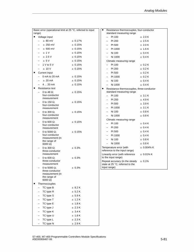
Analog Modules
5-81S7-400, M7-400 Programmable Controllers Module SpecificationsA5E00069467-06
Basic error (operational limit at 25 °C, referred to inputrange)
• Voltage input
– 80 mV
– 250 mV
– 500 mV
– 1 V
– 2.5 V
– 5 V
– 1 V to 5 V
– 10 V
0.17%
0.15%
0.15%
0.15%
0.15%
0.15%
0.15%
0.15%
• Current input
– 0 mA to 20 mA
– 20 mA
– 4 ... 20 mA
0.15%
0.15%
0.15%
• Resistance test
– 0 to 48 ; four-conductormeasurement
0.15%
– 0 to 150 , four-conductormeasurement
0.15%
– 0 to 300 four-conductormeasurement
0.15%
– 0 to 600 ; four-conductormeasurement
0.15%
– 0 to 5000 ;four-conductormeasurement (inthe range of6000 )
0.15%
– 0 to 300 ; three-conductormeasurement
0.3%
– 0 to 600 ; three-conductormeasurement
0.3%
– 0 to 5000 Ω; three-conductormeasurement (inthe range of6000 )
0.3%
• Thermocouples
– TC type B
– TC type R
– TC type S
– TC type T
– TC type E
– TC type J
– TC type K
– TC type U
– TC type L
– TC type N
8.2 K
5.2 K
5.9 K
1.2 K
1.8 K
2.3 K
3.4 K
1.8 K
2.3 K
2.9 K
• Resistance thermocouples, four-conductorstandard measuring range
– Pt 100
– Pt 200
– Pt 500
– Pt 1000
– Ni 100
– Ni 1000
2.0 K
2.5 K
2.0 K
1.6 K
0.4 K
0.4 K
Climatic measuring range
– Pt 100
– Pt 200
– Pt 500
– Pt 1000
– Ni 100
– Ni 1000
0.2 K
0.2 K
0.2 K
0.2 K
0.4 K
0.4 K
• Resistance thermocouples, three-conductorstandard measuring range
– Pt 100
– Pt 200
– Pt 500
– Pt 1000
– Ni 100
– Ni 1000
3.1 K
4.9 K
3.9 K
3.1 K
0.8 K
0.8 K
Climatic measuring range
– Pt 100
– Pt 200
– Pt 500
– Pt 1000
– Ni 100
– Ni 1000
0.4 K
0.4 K
0.4 K
0.4 K
0.8 K
0.8 K
Temperature error (withreference to the input range)
0.004% K
Linearity error (with referenceto the input range)
0.01% K
Repeat accuracy (in the steadystate at 25 °C, referred to theinput range)
0.1%
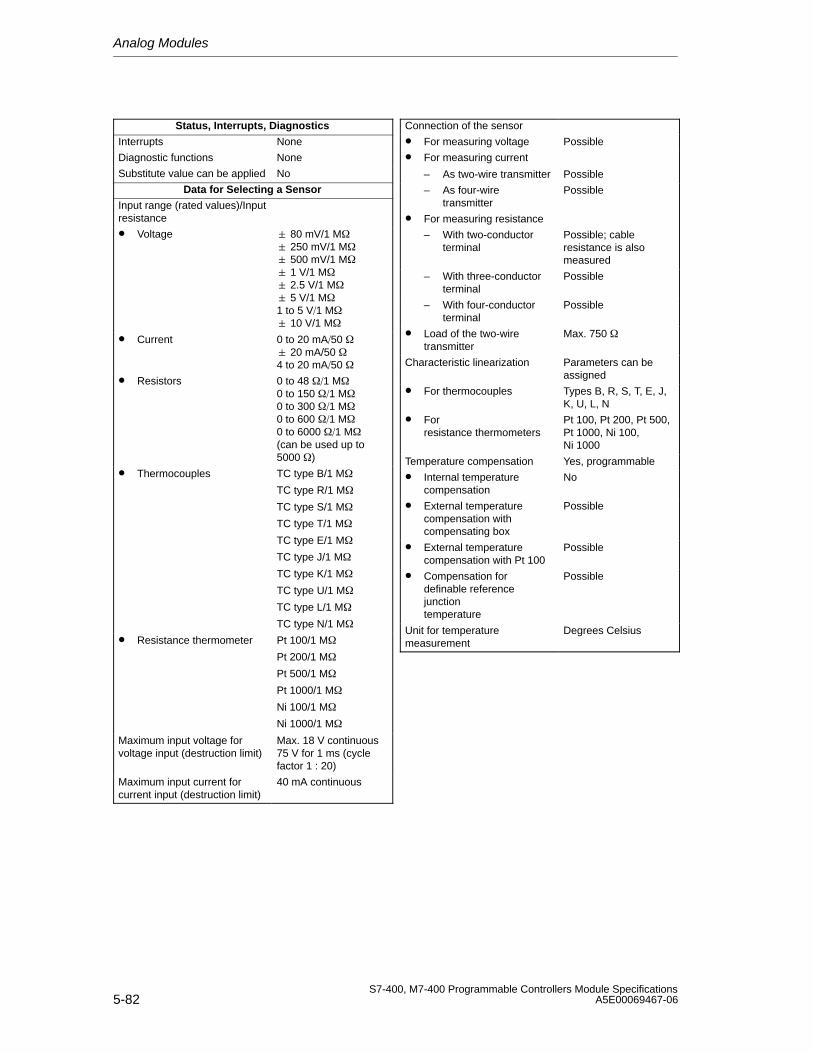
Analog Modules
5-82S7-400, M7-400 Programmable Controllers Module Specifications
A5E00069467-06
Status, Interrupts, Diagnostics
Interrupts None
Diagnostic functions None
Substitute value can be applied No
Data for Selecting a Sensor
Input range (rated values)/Inputresistance
• Voltage 80 mV/1 M 250 mV/1 M 500 mV/1 M 1 V/1 M 2.5 V/1 M 5 V/1 M1 to 5 V1 M 10 V/1 M
• Current 0 to 20 mA50 20 mA/50 4 to 20 mA50
• Resistors 0 to 48 1 M0 to 150 1 M0 to 300 1 M0 to 600 1 M0 to 6000 1 M(can be used up to5000 )
• Thermocouples TC type B/1 M
TC type R/1 M
TC type S/1 M
TC type T/1 M
TC type E/1 M
TC type J/1 M
TC type K/1 M
TC type U/1 M
TC type L/1 M
TC type N/1 M
• Resistance thermometer Pt 100/1 M
Pt 200/1 M
Pt 500/1 M
Pt 1000/1 M
Ni 100/1 M
Ni 1000/1 M
Maximum input voltage forvoltage input (destruction limit)
Max. 18 V continuous75 V for 1 ms (cyclefactor 1 : 20)
Maximum input current forcurrent input (destruction limit)
40 mA continuous
Connection of the sensor
• For measuring voltage Possible
• For measuring current
– As two-wire transmitter Possible
– As four-wiretransmitter
Possible
• For measuring resistance
– With two-conductorterminal
Possible; cableresistance is alsomeasured
– With three-conductorterminal
Possible
– With four-conductorterminal
Possible
• Load of the two-wiretransmitter
Max. 750
Characteristic linearization Parameters can beassigned
• For thermocouples Types B, R, S, T, E, J,K, U, L, N
• For resistance thermometers
Pt 100, Pt 200, Pt 500,Pt 1000, Ni 100, Ni 1000
Temperature compensation Yes, programmable
• Internal temperaturecompensation
No
• External temperaturecompensation withcompensating box
Possible
• External temperaturecompensation with Pt 100
Possible
• Compensation fordefinable referencejunctiontemperature
Possible
Unit for temperaturemeasurement
Degrees Celsius
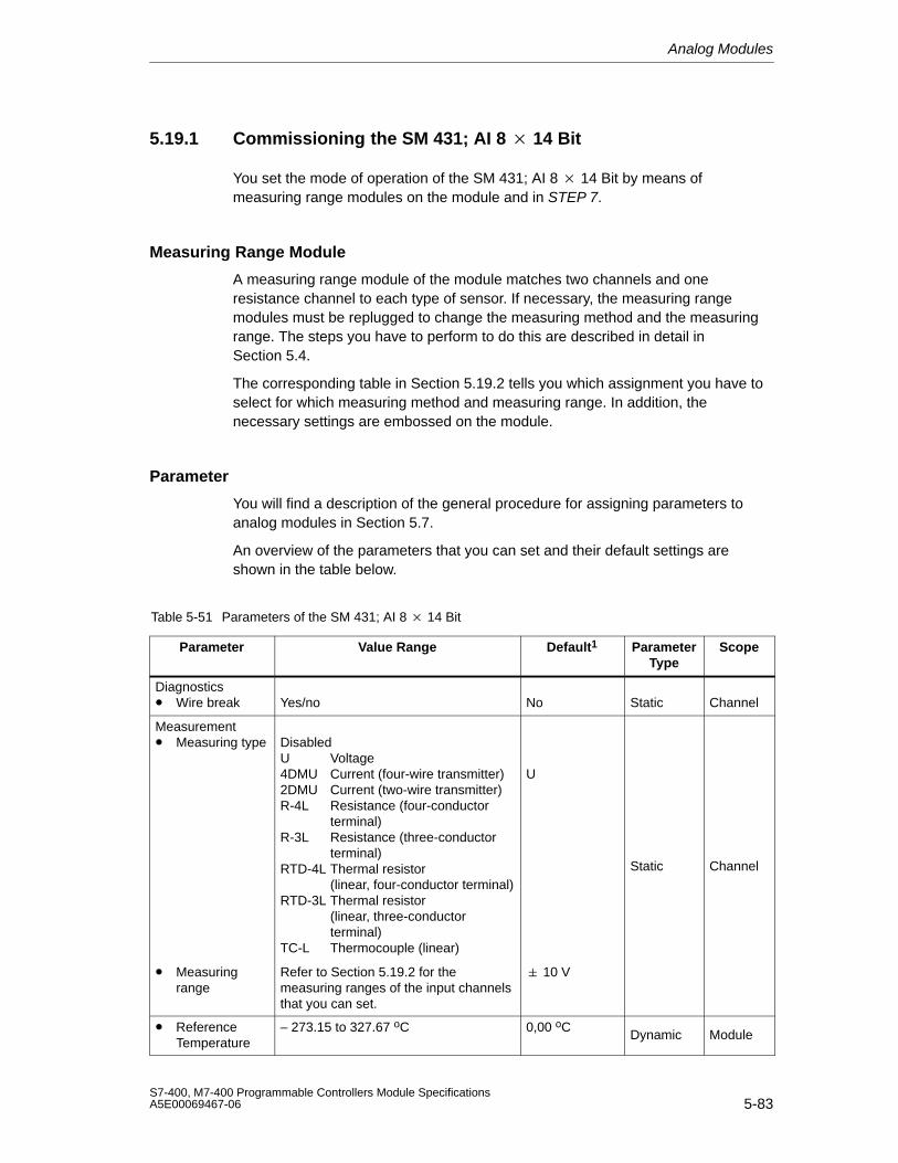
Analog Modules
5-83S7-400, M7-400 Programmable Controllers Module SpecificationsA5E00069467-06
5.19.1 Commissioning the SM 431; AI 8 14 Bit
You set the mode of operation of the SM 431; AI 8 14 Bit by means ofmeasuring range modules on the module and in STEP 7.
Measuring Range Module
A measuring range module of the module matches two channels and oneresistance channel to each type of sensor. If necessary, the measuring rangemodules must be replugged to change the measuring method and the measuringrange. The steps you have to perform to do this are described in detail inSection 5.4.
The corresponding table in Section 5.19.2 tells you which assignment you have toselect for which measuring method and measuring range. In addition, thenecessary settings are embossed on the module.
Parameter
You will find a description of the general procedure for assigning parameters toanalog modules in Section 5.7.
An overview of the parameters that you can set and their default settings areshown in the table below.
Table 5-51 Parameters of the SM 431; AI 8 14 Bit
Parameter Value Range Default1 ParameterType
Scope
Diagnostics• Wire break Yes/no No Static Channel
Measurement• Measuring type Disabled
U Voltage4DMU Current (four-wire transmitter)2DMU Current (two-wire transmitter)R-4L Resistance (four-conductor
terminal)R-3L Resistance (three-conductor
terminal)RTD-4L Thermal resistor
(linear, four-conductor terminal)RTD-3L Thermal resistor
(linear, three-conductor terminal)
TC-L Thermocouple (linear)
U
Static Channel
• Measuringrange
Refer to Section 5.19.2 for themeasuring ranges of the input channelsthat you can set.
10 V
• ReferenceTemperature
– 273.15 to 327.67 oC 0,00 oCDynamic Module
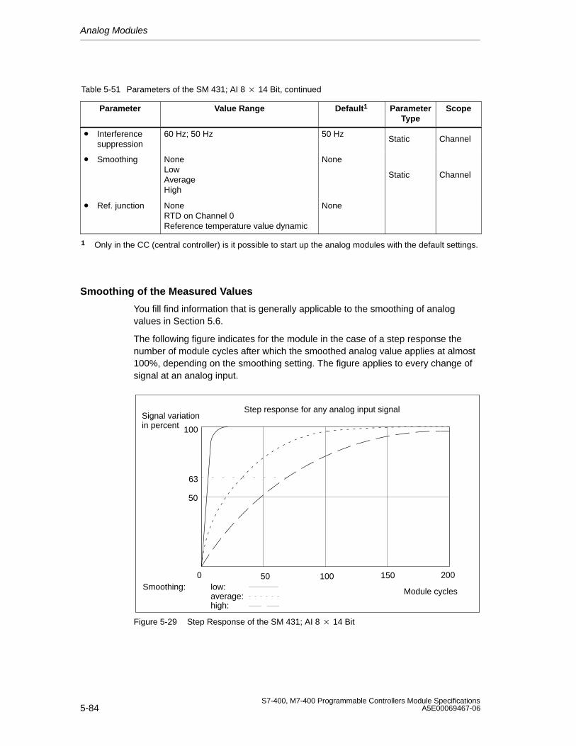
Analog Modules
5-84S7-400, M7-400 Programmable Controllers Module Specifications
A5E00069467-06
Table 5-51 Parameters of the SM 431; AI 8 14 Bit, continued
Parameter ScopeParameterType
Default1Value Range
• Interferencesuppression
60 Hz; 50 Hz 50 HzStatic Channel
• Smoothing NoneLowAverageHigh
None
Static Channel
• Ref. junction NoneRTD on Channel 0Reference temperature value dynamic
None
1 Only in the CC (central controller) is it possible to start up the analog modules with the default settings.
Smoothing of the Measured Values
You fill find information that is generally applicable to the smoothing of analogvalues in Section 5.6.
The following figure indicates for the module in the case of a step response thenumber of module cycles after which the smoothed analog value applies at almost100%, depending on the smoothing setting. The figure applies to every change ofsignal at an analog input.
50
100
0
63
50 100 150 200Smoothing: low:
average:high:
Module cycles
Signal variationin percent
Step response for any analog input signal
Figure 5-29 Step Response of the SM 431; AI 8 14 Bit
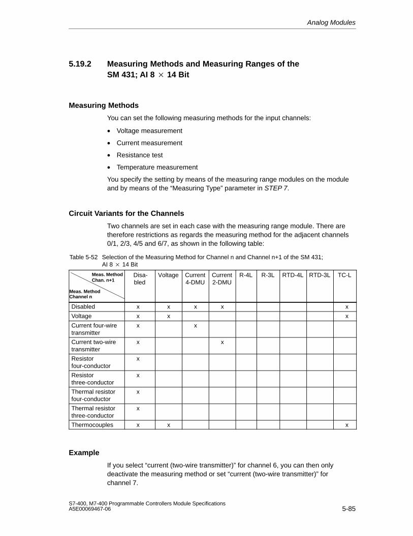
Analog Modules
5-85S7-400, M7-400 Programmable Controllers Module SpecificationsA5E00069467-06
5.19.2 Measuring Methods and Measuring Ranges of theSM 431; AI 8 14 Bit
Measuring Methods
You can set the following measuring methods for the input channels:
• Voltage measurement
• Current measurement
• Resistance test
• Temperature measurement
You specify the setting by means of the measuring range modules on the moduleand by means of the “Measuring Type” parameter in STEP 7.
Circuit Variants for the Channels
Two channels are set in each case with the measuring range module. There aretherefore restrictions as regards the measuring method for the adjacent channels0/1, 2/3, 4/5 and 6/7, as shown in the following table:
Table 5-52 Selection of the Measuring Method for Channel n and Channel n+1 of the SM 431;AI 8 14 Bit
Meas. MethodChan. n+1
Meas. MethodChannel n
Disa-bled
Voltage Current4-DMU
Current2-DMU
R-4L R-3L RTD-4L RTD-3L TC-L
Disabled x x x x x
Voltage x x x
Current four-wiretransmitter
x x
Current two-wiretransmitter
x x
Resistor four-conductor
x
Resistor three-conductor
x
Thermal resistorfour-conductor
x
Thermal resistorthree-conductor
x
Thermocouples x x x
Example
If you select “current (two-wire transmitter)” for channel 6, you can then onlydeactivate the measuring method or set “current (two-wire transmitter)” forchannel 7.
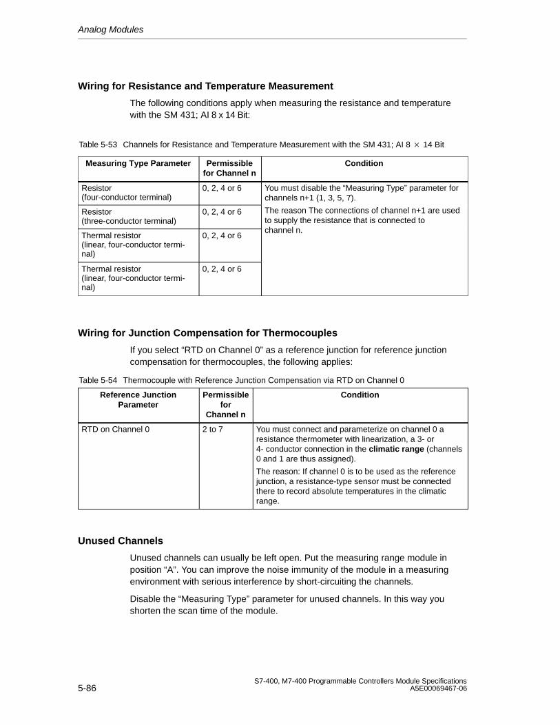
Analog Modules
5-86S7-400, M7-400 Programmable Controllers Module Specifications
A5E00069467-06
Wiring for Resistance and Temperature Measurement
The following conditions apply when measuring the resistance and temperaturewith the SM 431; AI 8 x 14 Bit:
Table 5-53 Channels for Resistance and Temperature Measurement with the SM 431; AI 8 14 Bit
Measuring Type Parameter Permissiblefor Channel n
Condition
Resistor (four-conductor terminal)
0, 2, 4 or 6 You must disable the “Measuring Type” parameter forchannels n+1 (1, 3, 5, 7).
Resistor (three-conductor terminal)
0, 2, 4 or 6 The reason The connections of channel n+1 are usedto supply the resistance that is connected to
Thermal resistor(linear, four-conductor termi-nal)
0, 2, 4 or 6channel n.
Thermal resistor(linear, four-conductor termi-nal)
0, 2, 4 or 6
Wiring for Junction Compensation for Thermocouples
If you select “RTD on Channel 0” as a reference junction for reference junctioncompensation for thermocouples, the following applies:
Table 5-54 Thermocouple with Reference Junction Compensation via RTD on Channel 0
Reference JunctionParameter
Permissiblefor
Channel n
Condition
RTD on Channel 0 2 to 7 You must connect and parameterize on channel 0 aresistance thermometer with linearization, a 3- or4- conductor connection in the climatic range (channels0 and 1 are thus assigned).
The reason: If channel 0 is to be used as the referencejunction, a resistance-type sensor must be connectedthere to record absolute temperatures in the climaticrange.
Unused Channels
Unused channels can usually be left open. Put the measuring range module inposition “A”. You can improve the noise immunity of the module in a measuringenvironment with serious interference by short-circuiting the channels.
Disable the “Measuring Type” parameter for unused channels. In this way youshorten the scan time of the module.
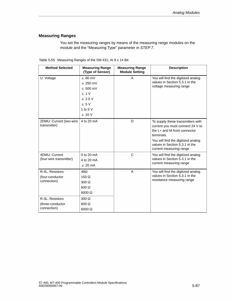
Analog Modules
5-87S7-400, M7-400 Programmable Controllers Module SpecificationsA5E00069467-06
Measuring Ranges
You set the measuring ranges by means of the measuring range modules on themodule and the “Measuring Type” parameter in STEP 7.
Table 5-55 Measuring Ranges of the SM 431; AI 8 x 14 Bit
Method Selected Measuring Range(Type of Sensor)
Measuring Range Module Setting
Description
U: Voltage 80 mV
250 mV
500 mV
1 V
A You will find the digitized analogvalues in Section 5.3.1 in thevoltage measuring range
2.5 V
5 V
1 to 5 V
10 V
2DMU: Current (two-wiretransmitter)
4 to 20 mA D To supply these transmitters withcurrent you must connect 24 V tothe L+ and M front connectorterminals.
You will find the digitized analogvalues in Section 5.3.1 in thecurrent measuring range
4DMU: Current(four-wire transmitter)
0 to 20 mA
4 to 20 mA
20 mA
C You will find the digitized analogvalues in Section 5.3.1 in thecurrent measuring range
R-4L: Resistors
(four-conductorconnection)
48
150
300
600
6000
A You will find the digitized analogvalues in Section 5.3.1 in theresistance measuring range
R-3L: Resistors
(three-conductorconnection)
300
600
6000
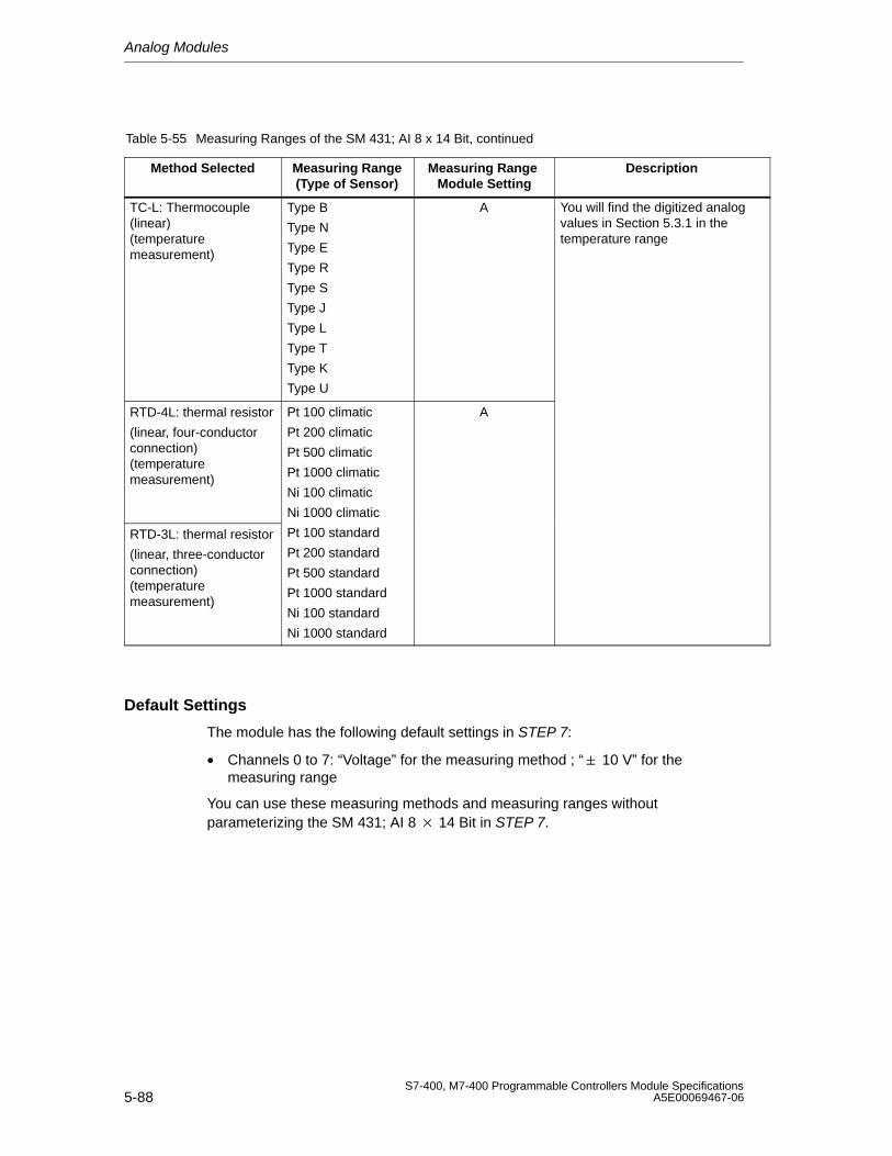
Analog Modules
5-88S7-400, M7-400 Programmable Controllers Module Specifications
A5E00069467-06
Table 5-55 Measuring Ranges of the SM 431; AI 8 x 14 Bit, continued
Method Selected DescriptionMeasuring Range Module Setting
Measuring Range(Type of Sensor)
TC-L: Thermocouple(linear)(temperaturemeasurement)
Type B
Type N
Type E
Type R
Type S
Type J
Type L
Type T
Type K
Type U
A You will find the digitized analogvalues in Section 5.3.1 in thetemperature range
RTD-4L: thermal resistor
(linear, four-conductorconnection)(temperaturemeasurement)
Pt 100 climatic
Pt 200 climatic
Pt 500 climatic
Pt 1000 climatic
Ni 100 climatic
Ni 1000 climatic
A
RTD-3L: thermal resistor
(linear, three-conductorconnection)(temperaturemeasurement)
Pt 100 standard
Pt 200 standard
Pt 500 standard
Pt 1000 standard
Ni 100 standard
Ni 1000 standard
Default Settings
The module has the following default settings in STEP 7:
• Channels 0 to 7: “Voltage” for the measuring method ; “ 10 V” for themeasuring range
You can use these measuring methods and measuring ranges withoutparameterizing the SM 431; AI 8 14 Bit in STEP 7.
Analog Modules
5-89S7-400, M7-400 Programmable Controllers Module SpecificationsA5E00069467-06
Wire Break Check for Temperature or Resistance Measurement
The wire break check is intended primarily for temperature measurements (TC,RTD) or resistance measurements. Always parameterize the wire break check inthese cases as this ensures that, in the event of a wire break, the measured valueprovided by the module accepts the data for overrun 7FFFH.
Special Characteristics of the Wire Break Check for the Voltage MeasurementMethods
In some transmitters, incorrect measured values may be obtained due to the factthat the wire break check is enabled. If so, disable the wire break check.
The reason Some transmitters try to correct the test current and in doing so corruptthe setpoint value provided.
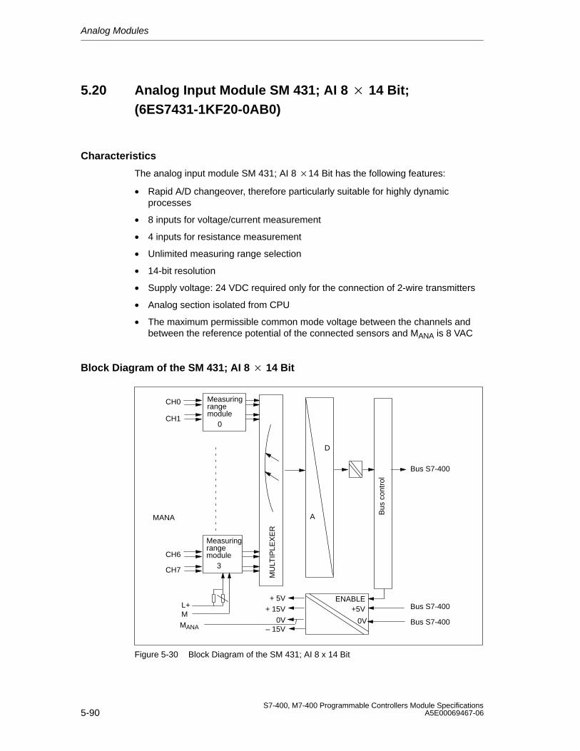
Analog Modules
5-90S7-400, M7-400 Programmable Controllers Module Specifications
A5E00069467-06
5.20 Analog Input Module SM 431; AI 8 14 Bit;(6ES7431-1KF20-0AB0)
Characteristics
The analog input module SM 431; AI 8 14 Bit has the following features:
• Rapid A/D changeover, therefore particularly suitable for highly dynamicprocesses
• 8 inputs for voltage/current measurement
• 4 inputs for resistance measurement
• Unlimited measuring range selection
• 14-bit resolution
• Supply voltage: 24 VDC required only for the connection of 2-wire transmitters
• Analog section isolated from CPU
• The maximum permissible common mode voltage between the channels andbetween the reference potential of the connected sensors and MANA is 8 VAC
Block Diagram of the SM 431; AI 8 14 Bit
CH0
CH1
CH6
CH7
+5V
0V0V – 15V
+ 5V + 15VL+
M
ENABLE
MU
LTIP
LEX
ER
Bus S7-400
Bus
con
trol
A
D
Bus S7-400
Bus S7-400
Measuring
3
rangemodule
Measuring
0
rangemodule
MANA
MANA
Figure 5-30 Block Diagram of the SM 431; AI 8 x 14 Bit
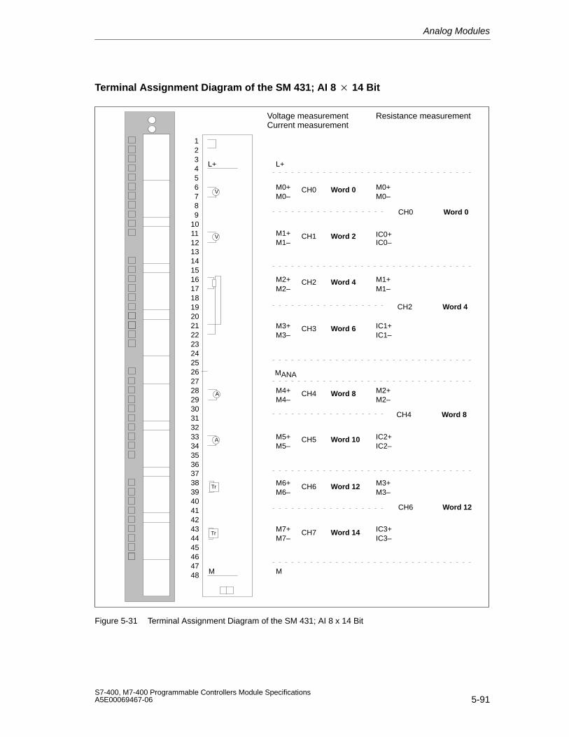
Analog Modules
5-91S7-400, M7-400 Programmable Controllers Module SpecificationsA5E00069467-06
Terminal Assignment Diagram of the SM 431; AI 8 14 Bit
Voltage measurementCurrent measurement
Resistance measurement
M1+
M2–
M3–
M4–
M5–
M6–
M7–
CH0
CH1
CH2
CH3
CH4
CH5
CH6
CH7
L+
V
A
A
M
Tr
Tr
L+
M0+M0–
M1–
M2+
M3+
M4+
M5+
M6+
M7+
M
M0+M0–
IC0+IC0–
M1+M1–
IC1+IC1–
M2+M2–
IC2+IC2–
M3+M3–
IC3+IC3–
CH0
CH2
CH4
CH6
V
MANA
293031323334353637
39404142434445464748
38
123456789
10111213141516171819202122232425262728
Word 0
Word 2
Word 4
Word 6
Word 8
Word 10
Word 12
Word 14
Word 0
Word 4
Word 8
Word 12
Figure 5-31 Terminal Assignment Diagram of the SM 431; AI 8 x 14 Bit
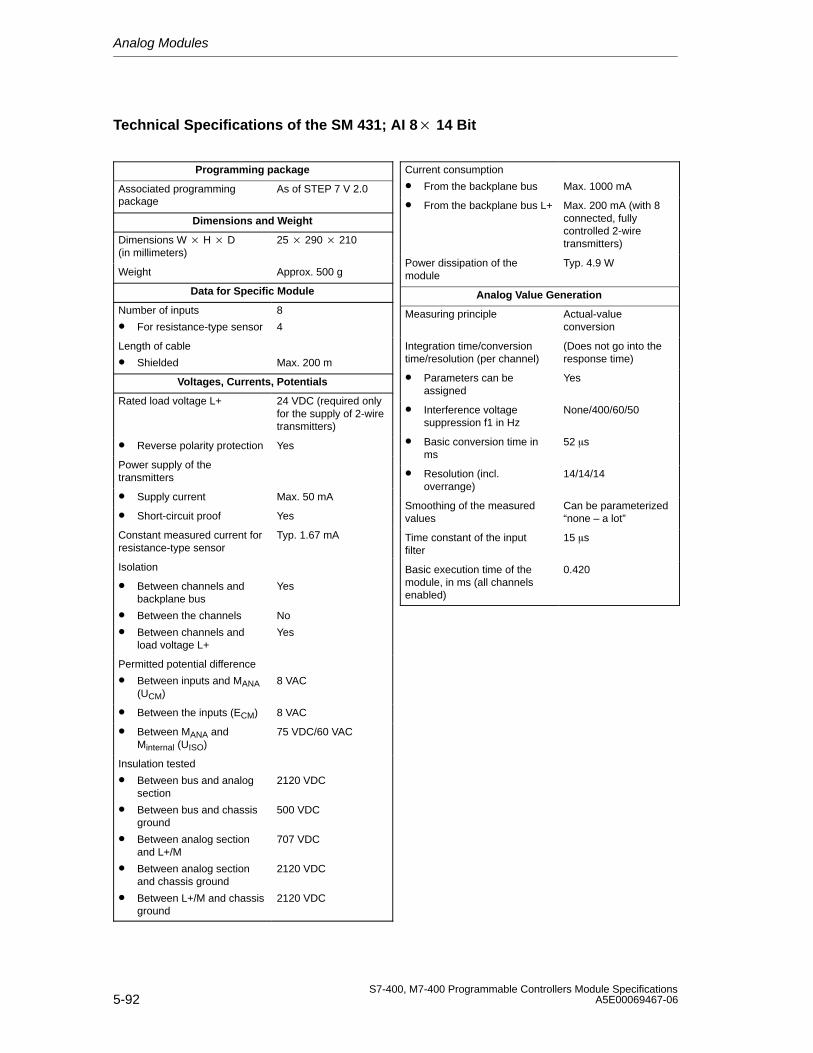
Analog Modules
5-92S7-400, M7-400 Programmable Controllers Module Specifications
A5E00069467-06
Technical Specifications of the SM 431; AI 8 14 Bit
Programming package
Associated programmingpackage
As of STEP 7 V 2.0
Dimensions and Weight
Dimensions W H D(in millimeters)
25 290 210
Weight Approx. 500 g
Data for Specific Module
Number of inputs
• For resistance-type sensor
8
4
Length of cable
• Shielded Max. 200 m
Voltages, Currents, Potentials
Rated load voltage L+ 24 VDC (required onlyfor the supply of 2-wiretransmitters)
• Reverse polarity protection Yes
Power supply of thetransmitters
• Supply current Max. 50 mA
• Short-circuit proof Yes
Constant measured current forresistance-type sensor
Typ. 1.67 mA
Isolation
• Between channels andbackplane bus
• Between the channels
• Between channels andload voltage L+
Yes
No
Yes
Permitted potential difference
• Between inputs and MANA(UCM)
8 VAC
• Between the inputs (ECM) 8 VAC
• Between MANA andMinternal (UISO)
75 VDC/60 VAC
Insulation tested
• Between bus and analogsection
• Between bus and chassisground
• Between analog sectionand L+/M
• Between analog sectionand chassis ground
• Between L+/M and chassisground
2120 VDC
500 VDC
707 VDC
2120 VDC
2120 VDC
Current consumption
• From the backplane bus Max. 1000 mA
• From the backplane bus L+ Max. 200 mA (with 8connected, fullycontrolled 2-wiretransmitters)
Power dissipation of themodule
Typ. 4.9 W
Analog Value Generation
Measuring principle Actual-valueconversion
Integration time/conversiontime/resolution (per channel)
(Does not go into theresponse time)
• Parameters can beassigned
Yes
• Interference voltagesuppression f1 in Hz
None/400/60/50
• Basic conversion time inms
52 s
• Resolution (incl.overrange)
14/14/14
Smoothing of the measuredvalues
Can be parameterized “none – a lot”
Time constant of the input filter
15 s
Basic execution time of themodule, in ms (all channelsenabled)
0.420
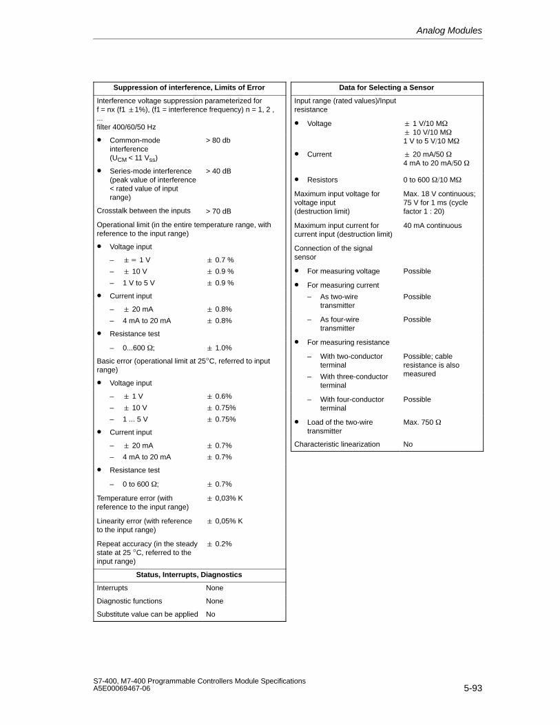
Analog Modules
5-93S7-400, M7-400 Programmable Controllers Module SpecificationsA5E00069467-06
Suppression of interference, Limits of Error
Interference voltage suppression parameterized for f = nx (f1 1%), (f1 = interference frequency) n = 1, 2 ,...filter 400/60/50 Hz
• Common-modeinterference (UCM < 11 Vss)
> 80 db
• Series-mode interference(peak value of interference < rated value of inputrange)
> 40 dB
Crosstalk between the inputs > 70 dB
Operational limit (in the entire temperature range, withreference to the input range)
• Voltage input
– 1 V
– 10 V
– 1 V to 5 V
0.7 %
0.9 %
0.9 %
• Current input
– 20 mA
– 4 mA to 20 mA
0.8%
0.8%
• Resistance test
– 0...600 ; 1.0%
Basic error (operational limit at 25°C, referred to inputrange)
• Voltage input
– 1 V
– 10 V
– 1 ... 5 V
0.6%
0.75%
0.75%
• Current input
– 20 mA
– 4 mA to 20 mA
0.7%
0.7%
• Resistance test
– 0 to 600 ; 0.7%
Temperature error (withreference to the input range)
0,03% K
Linearity error (with referenceto the input range)
0,05% K
Repeat accuracy (in the steadystate at 25 °C, referred to theinput range)
0.2%
Status, Interrupts, Diagnostics
Interrupts None
Diagnostic functions None
Substitute value can be applied No
Data for Selecting a Sensor
Input range (rated values)/Inputresistance
• Voltage 1 V/10 M 10 V/10 M1 V to 5 V10 M
• Current 20 mA/50 4 mA to 20 mA50
• Resistors 0 to 600 10 M
Maximum input voltage forvoltage input (destruction limit)
Max. 18 V continuous;75 V for 1 ms (cyclefactor 1 : 20)
Maximum input current forcurrent input (destruction limit)
40 mA continuous
Connection of the signalsensor
• For measuring voltage Possible
• For measuring current
– As two-wiretransmitter
Possible
– As four-wiretransmitter
Possible
• For measuring resistance
– With two-conductorterminal
– With three-conductorterminal
Possible; cableresistance is alsomeasured
– With four-conductorterminal
Possible
• Load of the two-wiretransmitter
Max. 750
Characteristic linearization No
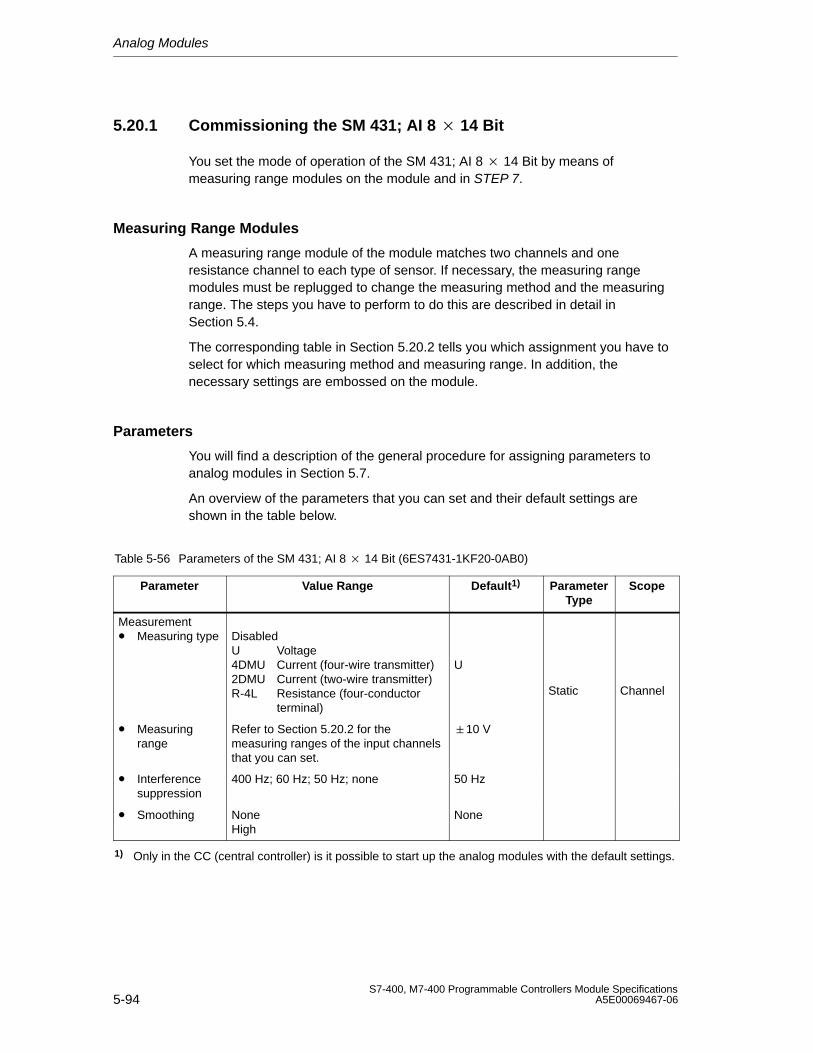
Analog Modules
5-94S7-400, M7-400 Programmable Controllers Module Specifications
A5E00069467-06
5.20.1 Commissioning the SM 431; AI 8 14 Bit
You set the mode of operation of the SM 431; AI 8 14 Bit by means ofmeasuring range modules on the module and in STEP 7.
Measuring Range Modules
A measuring range module of the module matches two channels and oneresistance channel to each type of sensor. If necessary, the measuring rangemodules must be replugged to change the measuring method and the measuringrange. The steps you have to perform to do this are described in detail inSection 5.4.
The corresponding table in Section 5.20.2 tells you which assignment you have toselect for which measuring method and measuring range. In addition, thenecessary settings are embossed on the module.
Parameters
You will find a description of the general procedure for assigning parameters toanalog modules in Section 5.7.
An overview of the parameters that you can set and their default settings areshown in the table below.
Table 5-56 Parameters of the SM 431; AI 8 14 Bit (6ES7431-1KF20-0AB0)
Parameter Value Range Default1) ParameterType
Scope
Measurement• Measuring type Disabled
U Voltage4DMU Current (four-wire transmitter)2DMU Current (two-wire transmitter)R-4L Resistance (four-conductor
terminal)
U
Static Channel
• Measuringrange
Refer to Section 5.20.2 for themeasuring ranges of the input channelsthat you can set.
10 V
• Interferencesuppression
400 Hz; 60 Hz; 50 Hz; none 50 Hz
• Smoothing NoneHigh
None
1) Only in the CC (central controller) is it possible to start up the analog modules with the default settings.
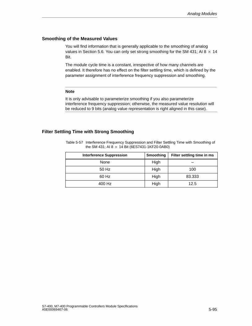
Analog Modules
5-95S7-400, M7-400 Programmable Controllers Module SpecificationsA5E00069467-06
Smoothing of the Measured Values
You will find information that is generally applicable to the smoothing of analogvalues in Section 5.6. You can only set strong smoothing for the SM 431; AI 8 14Bit.
The module cycle time is a constant, irrespective of how many channels areenabled. It therefore has no effect on the filter settling time, which is defined by theparameter assignment of interference frequency suppression and smoothing.
Note
It is only advisable to parameterize smoothing if you also parameterizeinterference frequency suppression; otherwise, the measured value resolution willbe reduced to 9 bits (analog value representation is right aligned in this case).
Filter Settling Time with Strong Smoothing
Table 5-57 Interference Frequency Suppression and Filter Settling Time with Smoothing ofthe SM 431; AI 8 14 Bit (6ES7431-1KF20-0AB0)
Interference Suppression Smoothing Filter settling time in ms
None High –
50 Hz High 100
60 Hz High 83.333
400 Hz High 12.5
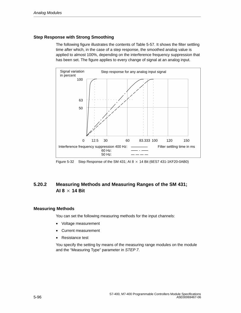
Analog Modules
5-96S7-400, M7-400 Programmable Controllers Module Specifications
A5E00069467-06
Step Response with Strong Smoothing
The following figure illustrates the contents of Table 5-57. It shows the filter settlingtime after which, in the case of a step response, the smoothed analog value isapplied to almost 100%, depending on the interference frequency suppression thathas been set. The figure applies to every change of signal at an analog input.
50
100
0
63
Interference frequency suppression 400 Hz: 60 Hz: 50 Hz:
Filter settling time in ms
Signal variationin percent
Step response for any analog input signal
12030 1506012.5 83.333 100
Figure 5-32 Step Response of the SM 431; AI 8 14 Bit (6ES7 431-1KF20-0AB0)
5.20.2 Measuring Methods and Measuring Ranges of the SM 431;AI 8 14 Bit
Measuring Methods
You can set the following measuring methods for the input channels:
• Voltage measurement
• Current measurement
• Resistance test
You specify the setting by means of the measuring range modules on the moduleand the “Measuring Type” parameter in STEP 7.
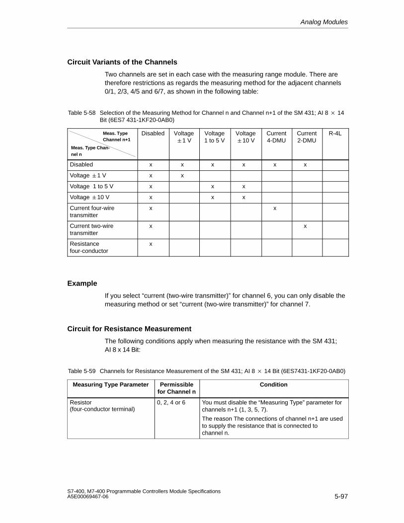
Analog Modules
5-97S7-400, M7-400 Programmable Controllers Module SpecificationsA5E00069467-06
Circuit Variants of the Channels
Two channels are set in each case with the measuring range module. There aretherefore restrictions as regards the measuring method for the adjacent channels0/1, 2/3, 4/5 and 6/7, as shown in the following table:
Table 5-58 Selection of the Measuring Method for Channel n and Channel n+1 of the SM 431; AI 8 14Bit (6ES7 431-1KF20-0AB0)
Meas. TypeChannel n+1
Meas. Type Chan-nel n
Disabled Voltage1 V
Voltage1 to 5 V
Voltage10 V
Current4-DMU
Current2-DMU
R-4L
Disabled x x x x x x
Voltage 1 V x x
Voltage 1 to 5 V x x x
Voltage 10 V x x x
Current four-wiretransmitter
x x
Current two-wiretransmitter
x x
Resistancefour-conductor
x
Example
If you select “current (two-wire transmitter)” for channel 6, you can only disable themeasuring method or set “current (two-wire transmitter)” for channel 7.
Circuit for Resistance Measurement
The following conditions apply when measuring the resistance with the SM 431;AI 8 x 14 Bit:
Table 5-59 Channels for Resistance Measurement of the SM 431; AI 8 14 Bit (6ES7431-1KF20-0AB0)
Measuring Type Parameter Permissiblefor Channel n
Condition
Resistor (four-conductor terminal)
0, 2, 4 or 6 You must disable the “Measuring Type” parameter forchannels n+1 (1, 3, 5, 7).
The reason The connections of channel n+1 are usedto supply the resistance that is connected tochannel n.
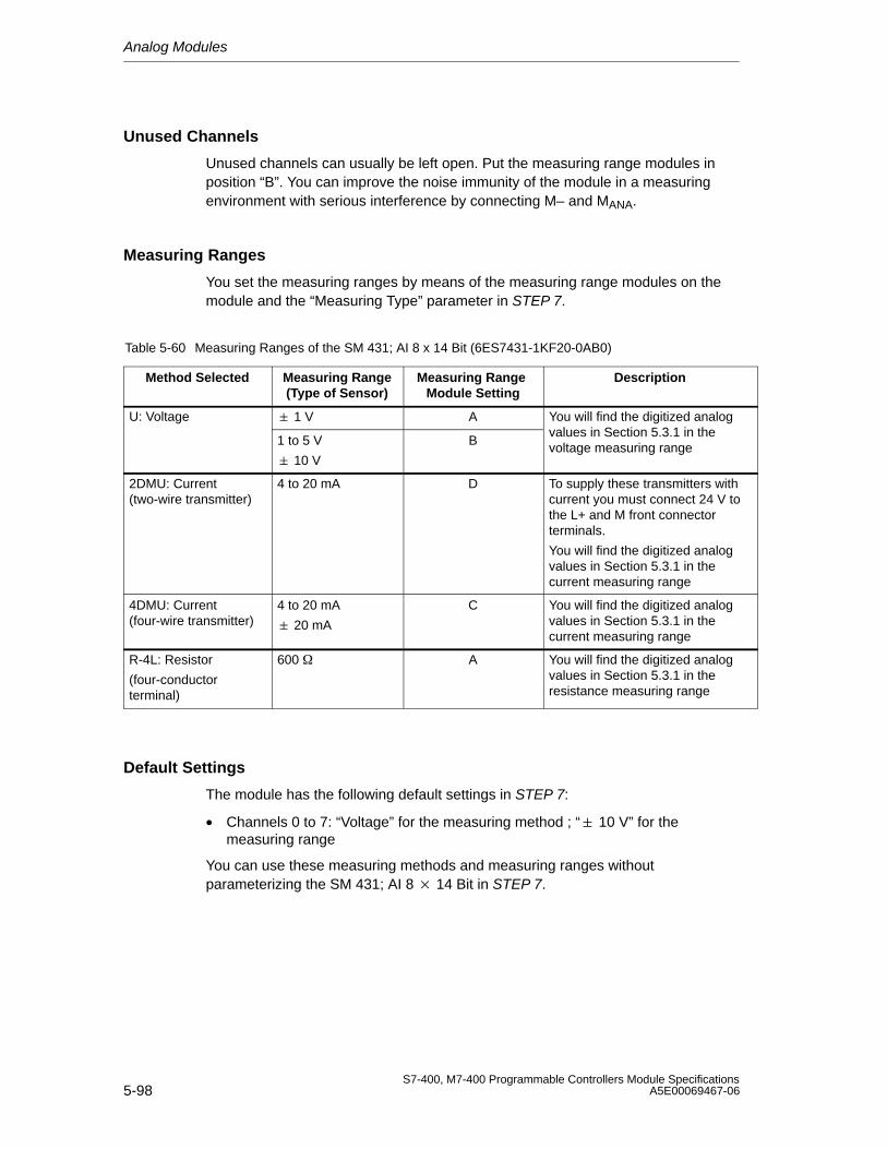
Analog Modules
5-98S7-400, M7-400 Programmable Controllers Module Specifications
A5E00069467-06
Unused Channels
Unused channels can usually be left open. Put the measuring range modules inposition “B”. You can improve the noise immunity of the module in a measuringenvironment with serious interference by connecting M– and MANA.
Measuring Ranges
You set the measuring ranges by means of the measuring range modules on themodule and the “Measuring Type” parameter in STEP 7.
Table 5-60 Measuring Ranges of the SM 431; AI 8 x 14 Bit (6ES7431-1KF20-0AB0)
Method Selected Measuring Range(Type of Sensor)
Measuring Range Module Setting
Description
U: Voltage 1 V A You will find the digitized analog
1 to 5 V
10 V
Bvalues in Section 5.3.1 in thevoltage measuring range
2DMU: Current(two-wire transmitter)
4 to 20 mA D To supply these transmitters withcurrent you must connect 24 V tothe L+ and M front connectorterminals.
You will find the digitized analogvalues in Section 5.3.1 in thecurrent measuring range
4DMU: Current(four-wire transmitter)
4 to 20 mA
20 mA
C You will find the digitized analogvalues in Section 5.3.1 in thecurrent measuring range
R-4L: Resistor
(four-conductorterminal)
600 A You will find the digitized analogvalues in Section 5.3.1 in theresistance measuring range
Default Settings
The module has the following default settings in STEP 7:
• Channels 0 to 7: “Voltage” for the measuring method ; “ 10 V” for themeasuring range
You can use these measuring methods and measuring ranges withoutparameterizing the SM 431; AI 8 14 Bit in STEP 7.
Analog Modules
5-99S7-400, M7-400 Programmable Controllers Module SpecificationsA5E00069467-06
5.21 Analog Input Module SM 431; AI 16 13 Bit;(6ES7431-0HH00-0AB0)
Characteristics
The analog input module SM 431; AI 13 16 Bit has the following features:
• 16 inputs for voltage/current measurement
• Unlimited measuring range selection
• 13-bit resolution
• Non-isolated between the analog section and bus
• The maximum permissible common mode voltage between the channels andthe reference potentials of the connected sensors and central ground point is 2VDC/VAC
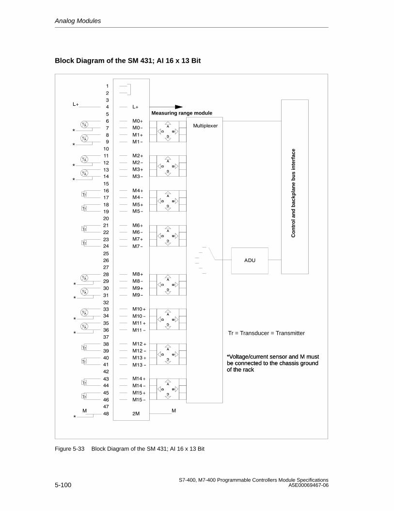
Analog Modules
5-100S7-400, M7-400 Programmable Controllers Module Specifications
A5E00069467-06
Block Diagram of the SM 431; AI 16 x 13 Bit
Tr
Tr
Tr
Tr
Tr
Tr
Tr
Tr
*
*Voltage/current sensor and M mustbe connected to the chassis groundof the rack
*Voltage/current sensor and M mustbe connected to the chassis groundof the rack
Tr = Transducer = Transmitter
*
*
*
*
*
*
*
*
Measuring range module
Co
ntr
ol a
nd
bac
kpla
ne
bu
s in
terf
ace
Figure 5-33 Block Diagram of the SM 431; AI 16 x 13 Bit
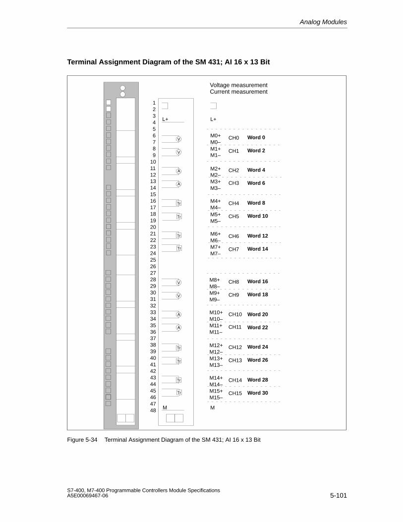
Analog Modules
5-101S7-400, M7-400 Programmable Controllers Module SpecificationsA5E00069467-06
Terminal Assignment Diagram of the SM 431; AI 16 x 13 Bit
Voltage measurementCurrent measurement
M1+
M2–
M3–
M4–
M5–
M6–
M7–
CH0
CH1
CH2
CH3
CH4
CH5
CH6
CH7
L+
M0+M0–
M1–
M2+
M3+
M4+
M5+
M6+
M7+
M
M8–
M9–
M8+
M9+
M10–
M11–
M10+
M11+
M12–
M13–
M12+
M13+
M14–
M15–
M14+
M15+
CH8
CH9
CH10
CH11
CH12
CH13
CH14
CH15
Word 0
Word 4
Word 8
Word 12
Word 16
Word 20
Word 24
Word 28
Word 2
Word 6
Word 10
Word 14
Word 18
Word 22
Word 26
Word 30
L+
M
293031323334353637
39404142434445464748
38
123456789
10111213141516171819202122232425262728
Tr
Tr
Tr
Tr
Tr
Tr
Tr
Tr
Figure 5-34 Terminal Assignment Diagram of the SM 431; AI 16 x 13 Bit
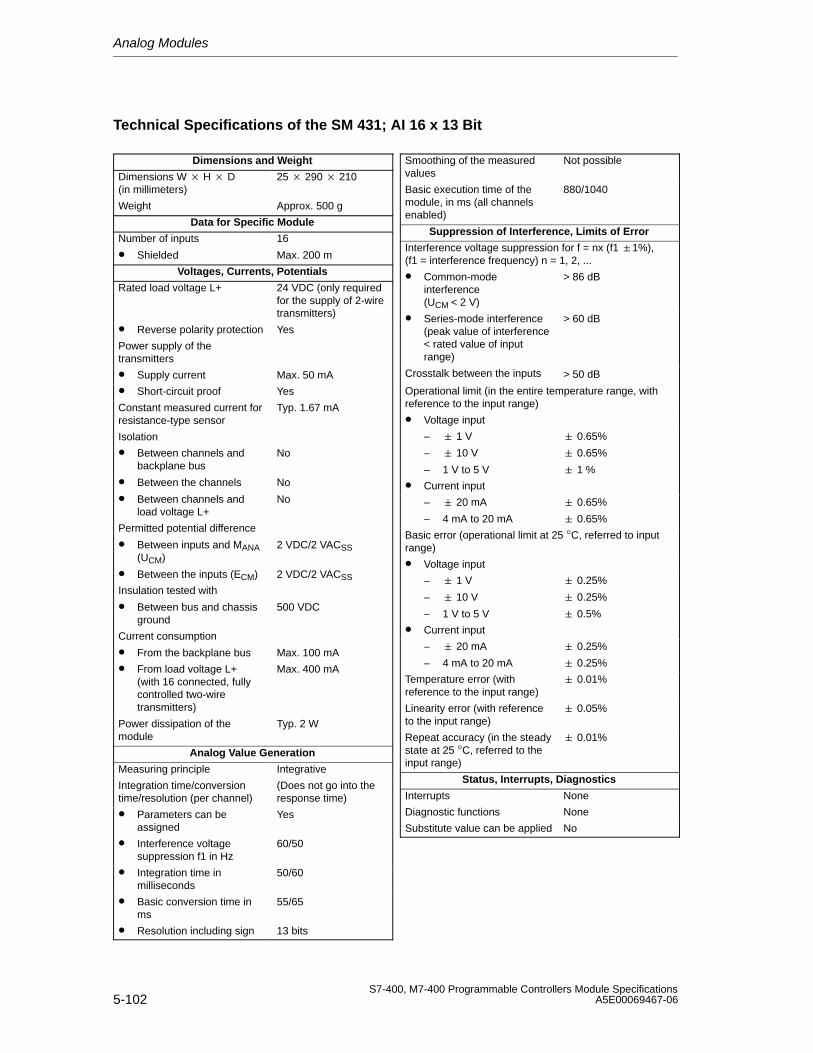
Analog Modules
5-102S7-400, M7-400 Programmable Controllers Module Specifications
A5E00069467-06
Technical Specifications of the SM 431; AI 16 x 13 Bit
Dimensions and Weight
Dimensions W H D(in millimeters)
25 290 210
Weight Approx. 500 g
Data for Specific Module
Number of inputs
• Shielded
16
Max. 200 m
Voltages, Currents, Potentials
Rated load voltage L+ 24 VDC (only requiredfor the supply of 2-wiretransmitters)
• Reverse polarity protection Yes
Power supply of thetransmitters
• Supply current Max. 50 mA
• Short-circuit proof Yes
Constant measured current forresistance-type sensor
Typ. 1.67 mA
Isolation
• Between channels andbackplane bus
• Between the channels
• Between channels andload voltage L+
No
No
No
Permitted potential difference
• Between inputs and MANA(UCM)
• Between the inputs (ECM)
2 VDC/2 VACSS
2 VDC/2 VACSS
Insulation tested with
• Between bus and chassisground
500 VDC
Current consumption
• From the backplane bus Max. 100 mA
• From load voltage L+ (with 16 connected, fullycontrolled two-wiretransmitters)
Max. 400 mA
Power dissipation of themodule
Typ. 2 W
Analog Value Generation
Measuring principle Integrative
Integration time/conversiontime/resolution (per channel)
(Does not go into theresponse time)
• Parameters can beassigned
Yes
• Interference voltagesuppression f1 in Hz
60/50
• Integration time inmilliseconds
50/60
• Basic conversion time inms
55/65
• Resolution including sign 13 bits
Smoothing of the measuredvalues
Not possible
Basic execution time of themodule, in ms (all channelsenabled)
880/1040
Suppression of Interference, Limits of Error
Interference voltage suppression for f = nx (f1 1%), (f1 = interference frequency) n = 1, 2, ...
• Common-modeinterference (UCM < 2 V)
> 86 dB
• Series-mode interference(peak value of interference < rated value of inputrange)
> 60 dB
Crosstalk between the inputs > 50 dB
Operational limit (in the entire temperature range, withreference to the input range)
• Voltage input
– 1 V
– 10 V
– 1 V to 5 V
0.65%
0.65%
1 %
• Current input
– 20 mA
– 4 mA to 20 mA
0.65%
0.65%
Basic error (operational limit at 25 °C, referred to inputrange)
• Voltage input
– 1 V
– 10 V
– 1 V to 5 V
0.25%
0.25%
0.5%
• Current input
– 20 mA
– 4 mA to 20 mA
0.25%
0.25%
Temperature error (withreference to the input range)
0.01%
Linearity error (with referenceto the input range)
0.05%
Repeat accuracy (in the steadystate at 25 °C, referred to theinput range)
0.01%
Status, Interrupts, Diagnostics
Interrupts None
Diagnostic functions None
Substitute value can be applied No
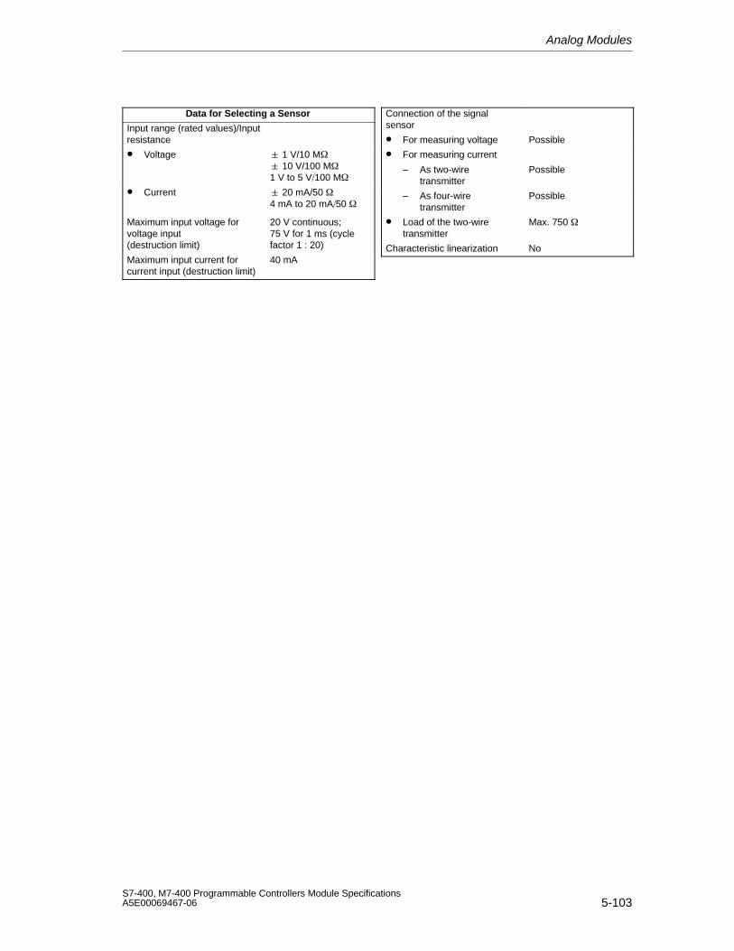
Analog Modules
5-103S7-400, M7-400 Programmable Controllers Module SpecificationsA5E00069467-06
Data for Selecting a Sensor
Input range (rated values)/Inputresistance
• Voltage 1 V/10 M 10 V/100 M1 V to 5 V100 M
• Current 20 mA/50 4 mA to 20 mA50
Maximum input voltage forvoltage input (destruction limit)
20 V continuous;75 V for 1 ms (cyclefactor 1 : 20)
Maximum input current forcurrent input (destruction limit)
40 mA
Connection of the signalsensor
• For measuring voltage Possible
• For measuring current
– As two-wiretransmitter
Possible
– As four-wiretransmitter
Possible
• Load of the two-wiretransmitter
Max. 750
Characteristic linearization No
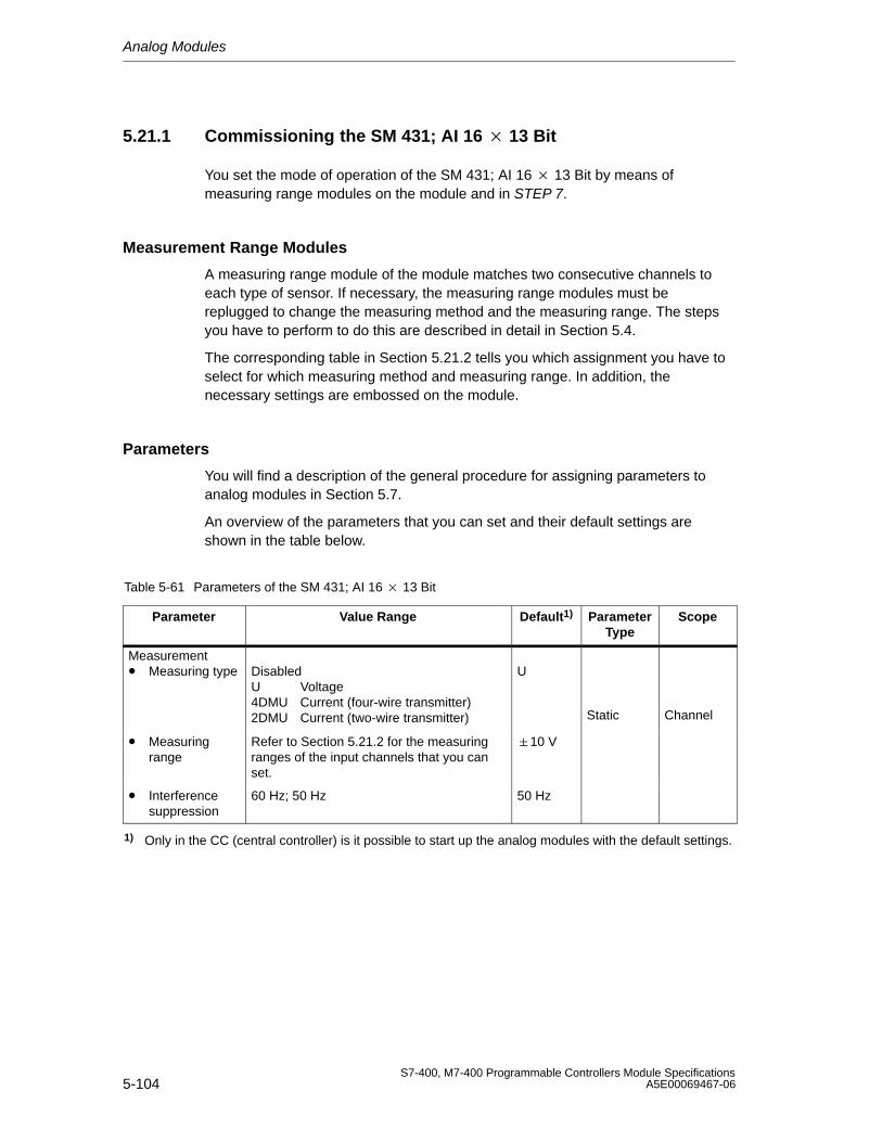
Analog Modules
5-104S7-400, M7-400 Programmable Controllers Module Specifications
A5E00069467-06
5.21.1 Commissioning the SM 431; AI 16 13 Bit
You set the mode of operation of the SM 431; AI 16 13 Bit by means ofmeasuring range modules on the module and in STEP 7.
Measurement Range Modules
A measuring range module of the module matches two consecutive channels toeach type of sensor. If necessary, the measuring range modules must bereplugged to change the measuring method and the measuring range. The stepsyou have to perform to do this are described in detail in Section 5.4.
The corresponding table in Section 5.21.2 tells you which assignment you have toselect for which measuring method and measuring range. In addition, thenecessary settings are embossed on the module.
Parameters
You will find a description of the general procedure for assigning parameters toanalog modules in Section 5.7.
An overview of the parameters that you can set and their default settings areshown in the table below.
Table 5-61 Parameters of the SM 431; AI 16 13 Bit
Parameter Value Range Default1) ParameterType
Scope
Measurement• Measuring type Disabled
U Voltage4DMU Current (four-wire transmitter)2DMU Current (two-wire transmitter)
U
Static Channel
• Measuringrange
Refer to Section 5.21.2 for the measuringranges of the input channels that you canset.
10 V
• Interferencesuppression
60 Hz; 50 Hz 50 Hz
1) Only in the CC (central controller) is it possible to start up the analog modules with the default settings.
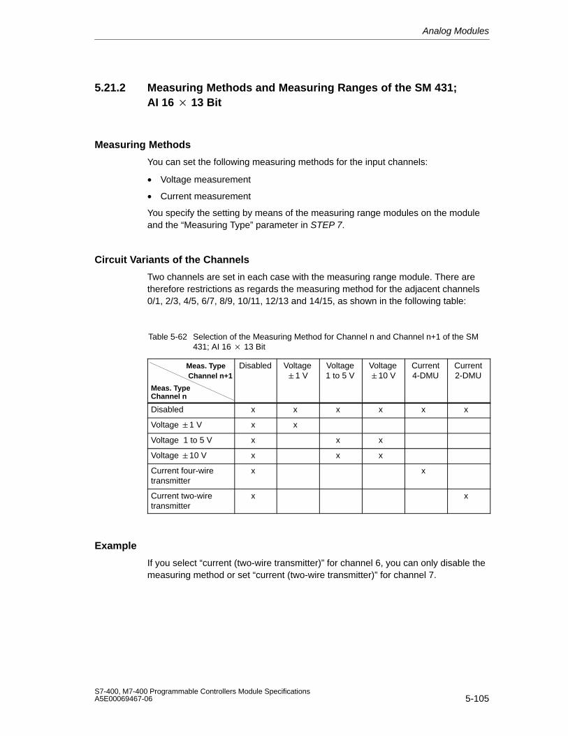
Analog Modules
5-105S7-400, M7-400 Programmable Controllers Module SpecificationsA5E00069467-06
5.21.2 Measuring Methods and Measuring Ranges of the SM 431;AI 16 13 Bit
Measuring Methods
You can set the following measuring methods for the input channels:
• Voltage measurement
• Current measurement
You specify the setting by means of the measuring range modules on the moduleand the “Measuring Type” parameter in STEP 7.
Circuit Variants of the Channels
Two channels are set in each case with the measuring range module. There aretherefore restrictions as regards the measuring method for the adjacent channels0/1, 2/3, 4/5, 6/7, 8/9, 10/11, 12/13 and 14/15, as shown in the following table:
Table 5-62 Selection of the Measuring Method for Channel n and Channel n+1 of the SM431; AI 16 13 Bit
Meas. Type Channel n+1
Meas. TypeChannel n
Disabled Voltage1 V
Voltage1 to 5 V
Voltage10 V
Current4-DMU
Current2-DMU
Disabled x x x x x x
Voltage 1 V x x
Voltage 1 to 5 V x x x
Voltage 10 V x x x
Current four-wiretransmitter
x x
Current two-wiretransmitter
x x
Example
If you select “current (two-wire transmitter)” for channel 6, you can only disable themeasuring method or set “current (two-wire transmitter)” for channel 7.
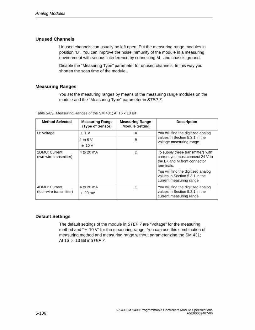
Analog Modules
5-106S7-400, M7-400 Programmable Controllers Module Specifications
A5E00069467-06
Unused Channels
Unused channels can usually be left open. Put the measuring range modules inposition “B”. You can improve the noise immunity of the module in a measuringenvironment with serious interference by connecting M– and chassis ground.
Disable the “Measuring Type” parameter for unused channels. In this way youshorten the scan time of the module.
Measuring Ranges
You set the measuring ranges by means of the measuring range modules on themodule and the “Measuring Type” parameter in STEP 7.
Table 5-63 Measuring Ranges of the SM 431; AI 16 x 13 Bit
Method Selected Measuring Range(Type of Sensor)
Measuring Range Module Setting
Description
U: Voltage 1 V A You will find the digitized analog
1 to 5 V
10 V
Bvalues in Section 5.3.1 in thevoltage measuring range
2DMU: Current(two-wire transmitter)
4 to 20 mA D To supply these transmitters withcurrent you must connect 24 V tothe L+ and M front connectorterminals.
You will find the digitized analogvalues in Section 5.3.1 in thecurrent measuring range
4DMU: Current(four-wire transmitter)
4 to 20 mA
20 mA
C You will find the digitized analogvalues in Section 5.3.1 in thecurrent measuring range
Default Settings
The default settings of the module in STEP 7 are “Voltage” for the measuringmethod and “ 10 V” for the measuring range. You can use this combination ofmeasuring method and measuring range without parameterizing the SM 431;AI 16 13 Bit inSTEP 7.
Analog Modules
5-107S7-400, M7-400 Programmable Controllers Module SpecificationsA5E00069467-06
5.22 Analog Input Module SM 431; AI 16 16 Bit;(6ES7431-7QH00-0AB0)
Characteristics
The analog input module SM 431; AI 16 16 Bit has the following features:
• 16 inputs for voltage/current and temperature measurement
• 8 inputs for resistance measurement
• Unlimited measuring range selection
• 16-bit resolution
• Programmable diagnostics
• Programmable diagnostic interrupt
• Programmable hardware interrupt when limit has been exceeded
• Programmable end-of-scan-cycle interrupt
• Analog section isolated from CPU
• The maximum permissible common mode voltage between the channels andbetween the channel and the central ground point is 120 VAC
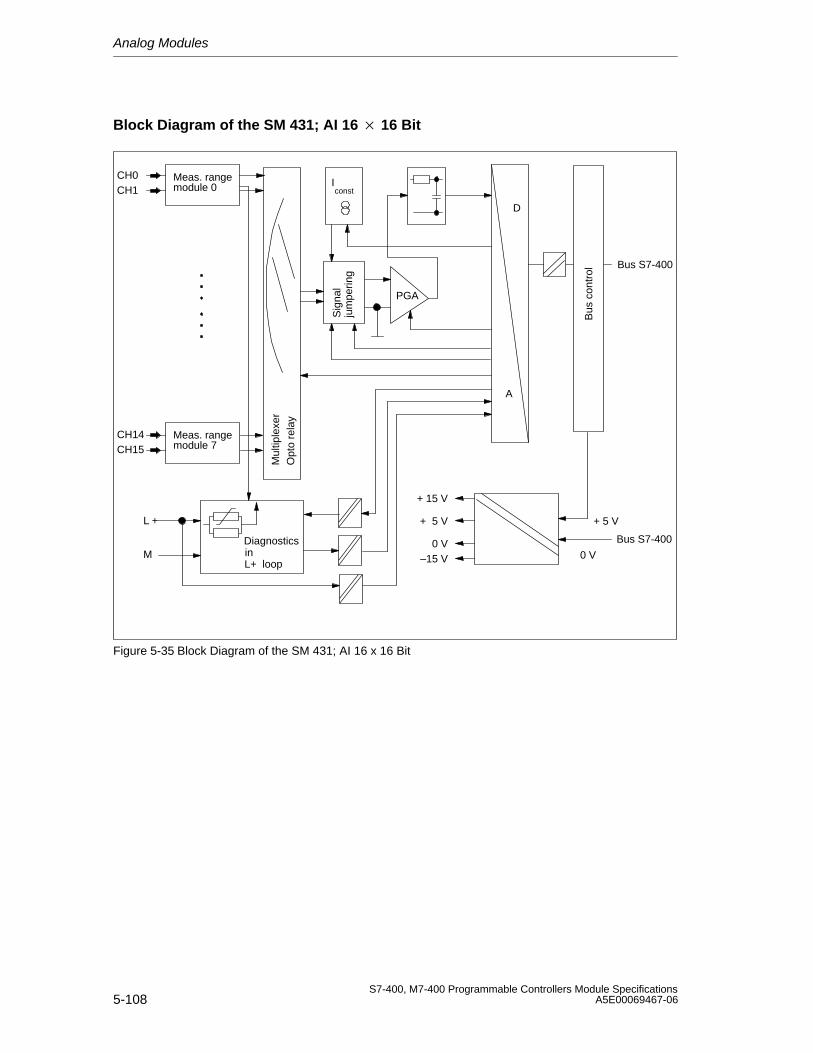
Analog Modules
5-108S7-400, M7-400 Programmable Controllers Module Specifications
A5E00069467-06
Block Diagram of the SM 431; AI 16 16 Bit
Bus S7-400
Bus
con
trol
A
D
CH0CH1
+ 15 V
+ 5 V
0 V–15 V
+ 5 V
0 V
Iconst
DiagnosticsinL+ loop
L +
M
PGA
Mul
tiple
xer
Opt
o re
lay
CH14CH15
Meas. range
Meas. range
module 0
module 7
Sig
nal
jum
perin
g
Bus S7-400
Figure 5-35 Block Diagram of the SM 431; AI 16 x 16 Bit
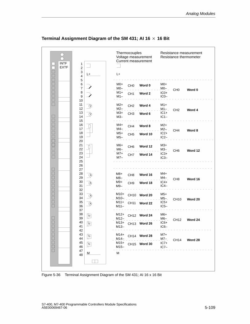
Analog Modules
5-109S7-400, M7-400 Programmable Controllers Module SpecificationsA5E00069467-06
Terminal Assignment Diagram of the SM 431; AI 16 16 Bit
ThermocouplesVoltage measurementCurrent measurement
Resistance measurementResistance thermometer
M1+
M2–
M3–
M4–
M5–
M6–
M7–
CH0
CH1
CH2
CH3
CH4
CH5
CH6
CH7
L+
V
A
A
M
Tr
Tr
L+
M0+M0–
M1–
M2+
M3+
M4+
M5+
M6+
M7+
M
M0+M0–IC0+IC0–
M1+M1–IC1+IC1–
M2+M2–IC2+IC2–
M3+M3–IC3+IC3–
CH0
CH2
CH4
CH6
V
M8–
M9–
M8+
M9+
M10–
M11–
M10+
M11+
M12–
M13–
M12+
M13+
M14–
M15–
M14+
M15+
CH8
CH9
CH10
CH11
CH12
CH13
CH14
CH15
M4+M4–IC4+IC4–
M5+M5–IC5+IC5–
M6+M6–IC6+IC6–
M7+M7–IC7+IC7–
CH8
CH10
CH12
CH14
A
A
Tr
Tr
293031323334353637
39404142434445464748
38
123456789
10111213141516171819202122232425262728
INTFEXTF
Word 0
Word 4
Word 8
Word 12
Word 16
Word 20
Word 24
Word 28
Word 2
Word 6
Word 10
Word 14
Word 18
Word 22
Word 26
Word 30
Word 0
Word 4
Word 8
Word 12
Word 16
Word 20
Word 24
Word 28
Figure 5-36 Terminal Assignment Diagram of the SM 431; AI 16 x 16 Bit
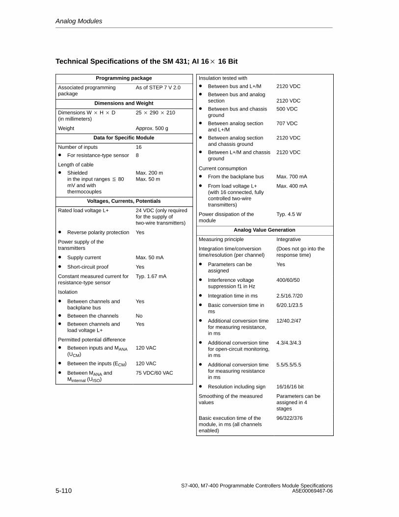
Analog Modules
5-110S7-400, M7-400 Programmable Controllers Module Specifications
A5E00069467-06
Technical Specifications of the SM 431; AI 16 16 Bit
Programming package
Associated programmingpackage
As of STEP 7 V 2.0
Dimensions and Weight
Dimensions W H D(in millimeters)
25 290 210
Weight Approx. 500 g
Data for Specific Module
Number of inputs
• For resistance-type sensor
16
8
Length of cable
• Shielded in the input ranges 80mV and withthermocouples
Max. 200 mMax. 50 m
Voltages, Currents, Potentials
Rated load voltage L+ 24 VDC (only requiredfor the supply oftwo-wire transmitters)
• Reverse polarity protection Yes
Power supply of the transmitters
• Supply current Max. 50 mA
• Short-circuit proof Yes
Constant measured current forresistance-type sensor
Typ. 1.67 mA
Isolation
• Between channels andbackplane bus
• Between the channels
• Between channels andload voltage L+
Yes
No
Yes
Permitted potential difference
• Between inputs and MANA(UCM)
120 VAC
• Between the inputs (ECM) 120 VAC
• Between MANA andMinternal (UISO)
75 VDC/60 VAC
Insulation tested with
• Between bus and L+/M
• Between bus and analogsection
• Between bus and chassisground
• Between analog sectionand L+/M
• Between analog sectionand chassis ground
• Between L+/M and chassisground
2120 VDC
2120 VDC
500 VDC
707 VDC
2120 VDC
2120 VDC
Current consumption
• From the backplane bus Max. 700 mA
• From load voltage L+ (with 16 connected, fullycontrolled two-wiretransmitters)
Max. 400 mA
Power dissipation of themodule
Typ. 4.5 W
Analog Value Generation
Measuring principle Integrative
Integration time/conversiontime/resolution (per channel)
(Does not go into theresponse time)
• Parameters can beassigned
Yes
• Interference voltagesuppression f1 in Hz
400/60/50
• Integration time in ms 2.5/16.7/20
• Basic conversion time inms
6/20.1/23.5
• Additional conversion timefor measuring resistance,in ms
12/40.2/47
• Additional conversion timefor open-circuit monitoring,in ms
4.3/4.3/4.3
• Additional conversion timefor measuring resistancein ms
5.5/5.5/5.5
• Resolution including sign 16/16/16 bit
Smoothing of the measuredvalues
Parameters can beassigned in 4 stages
Basic execution time of themodule, in ms (all channelsenabled)
96/322/376
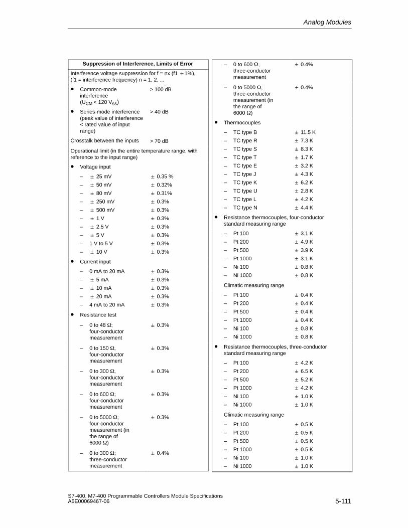
Analog Modules
5-111S7-400, M7-400 Programmable Controllers Module SpecificationsA5E00069467-06
Suppression of Interference, Limits of Error
Interference voltage suppression for f = nx (f1 1%), (f1 = interference frequency) n = 1, 2, ...
• Common-modeinterference (UCM < 120 Vss)
> 100 dB
• Series-mode interference(peak value of interference < rated value of inputrange)
> 40 dB
Crosstalk between the inputs > 70 dB
Operational limit (in the entire temperature range, withreference to the input range)
• Voltage input
– 25 mV
– 50 mV
– 80 mV
– 250 mV
– 500 mV
– 1 V
– 2.5 V
– 5 V
– 1 V to 5 V
– 10 V
0.35 %
0.32%
0.31%
0.3%
0.3%
0.3%
0.3%
0.3%
0.3%
0.3%
• Current input
– 0 mA to 20 mA
– 5 mA
– 10 mA
– 20 mA
– 4 mA to 20 mA
0.3%
0.3%
0.3%
0.3%
0.3%
• Resistance test
– 0 to 48 ;four-conductormeasurement
0.3%
– 0 to 150 , four-conductormeasurement
0.3%
– 0 to 300 four-conductormeasurement
0.3%
– 0 to 600 ; four-conductormeasurement
0.3%
– 0 to 5000 ;four-conductormeasurement (inthe range of6000 )
0.3%
– 0 to 300 ; three-conductormeasurement
0.4%
– 0 to 600 ; three-conductormeasurement
0.4%
– 0 to 5000 Ω; three-conductormeasurement (inthe range of6000 )
0.4%
• Thermocouples
– TC type B
– TC type R
– TC type S
– TC type T
– TC type E
– TC type J
– TC type K
– TC type U
– TC type L
– TC type N
11.5 K
7.3 K
8.3 K
1.7 K
3.2 K
4.3 K
6.2 K
2.8 K
4.2 K
4.4 K
• Resistance thermocouples, four-conductorstandard measuring range
– Pt 100
– Pt 200
– Pt 500
– Pt 1000
– Ni 100
– Ni 1000
3.1 K
4.9 K
3.9 K
3.1 K
0.8 K
0.8 K
Climatic measuring range
– Pt 100
– Pt 200
– Pt 500
– Pt 1000
– Ni 100
– Ni 1000
0.4 K
0.4 K
0.4 K
0.4 K
0.8 K
0.8 K
• Resistance thermocouples, three-conductorstandard measuring range
– Pt 100
– Pt 200
– Pt 500
– Pt 1000
– Ni 100
– Ni 1000
4.2 K
6.5 K
5.2 K
4.2 K
1.0 K
1.0 K
Climatic measuring range
– Pt 100
– Pt 200
– Pt 500
– Pt 1000
– Ni 100
– Ni 1000
0.5 K
0.5 K
0.5 K
0.5 K
1.0 K
1.0 K
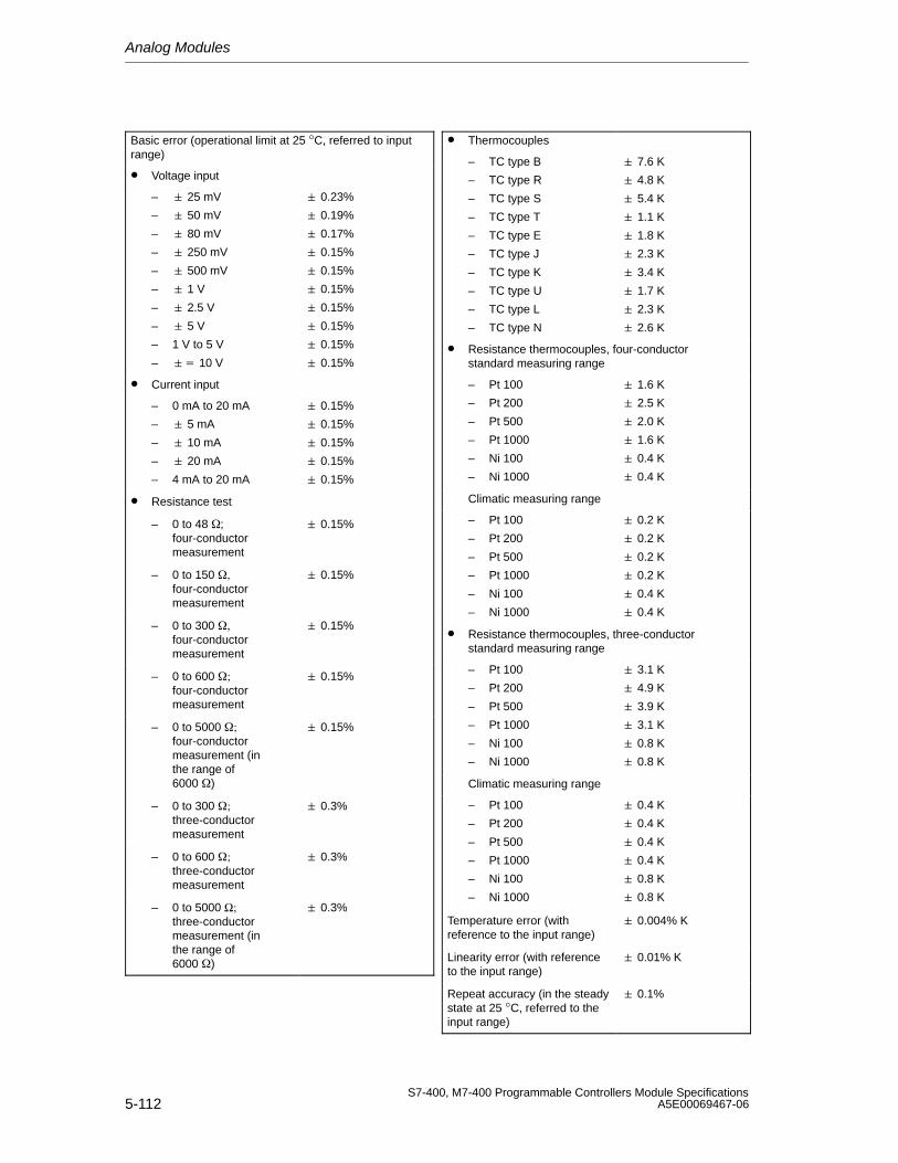
Analog Modules
5-112S7-400, M7-400 Programmable Controllers Module Specifications
A5E00069467-06
Basic error (operational limit at 25 °C, referred to inputrange)
• Voltage input
– 25 mV
– 50 mV
– 80 mV
– 250 mV
– 500 mV
– 1 V
– 2.5 V
– 5 V
– 1 V to 5 V
– 10 V
0.23%
0.19%
0.17%
0.15%
0.15%
0.15%
0.15%
0.15%
0.15%
0.15%
• Current input
– 0 mA to 20 mA
– 5 mA
– 10 mA
– 20 mA
– 4 mA to 20 mA
0.15%
0.15%
0.15%
0.15%
0.15%
• Resistance test
– 0 to 48 ;four-conductormeasurement
0.15%
– 0 to 150 , four-conductormeasurement
0.15%
– 0 to 300 four-conductormeasurement
0.15%
– 0 to 600 ; four-conductormeasurement
0.15%
– 0 to 5000 ;four-conductormeasurement (inthe range of6000 )
0.15%
– 0 to 300 ; three-conductormeasurement
0.3%
– 0 to 600 ; three-conductormeasurement
0.3%
– 0 to 5000 Ω; three-conductormeasurement (inthe range of6000 )
0.3%
• Thermocouples
– TC type B
– TC type R
– TC type S
– TC type T
– TC type E
– TC type J
– TC type K
– TC type U
– TC type L
– TC type N
7.6 K
4.8 K
5.4 K
1.1 K
1.8 K
2.3 K
3.4 K
1.7 K
2.3 K
2.6 K
• Resistance thermocouples, four-conductorstandard measuring range
– Pt 100
– Pt 200
– Pt 500
– Pt 1000
– Ni 100
– Ni 1000
1.6 K
2.5 K
2.0 K
1.6 K
0.4 K
0.4 K
Climatic measuring range
– Pt 100
– Pt 200
– Pt 500
– Pt 1000
– Ni 100
– Ni 1000
0.2 K
0.2 K
0.2 K
0.2 K
0.4 K
0.4 K
• Resistance thermocouples, three-conductorstandard measuring range
– Pt 100
– Pt 200
– Pt 500
– Pt 1000
– Ni 100
– Ni 1000
3.1 K
4.9 K
3.9 K
3.1 K
0.8 K
0.8 K
Climatic measuring range
– Pt 100
– Pt 200
– Pt 500
– Pt 1000
– Ni 100
– Ni 1000
0.4 K
0.4 K
0.4 K
0.4 K
0.8 K
0.8 K
Temperature error (withreference to the input range)
0.004% K
Linearity error (with referenceto the input range)
0.01% K
Repeat accuracy (in the steadystate at 25 °C, referred to theinput range)
0.1%
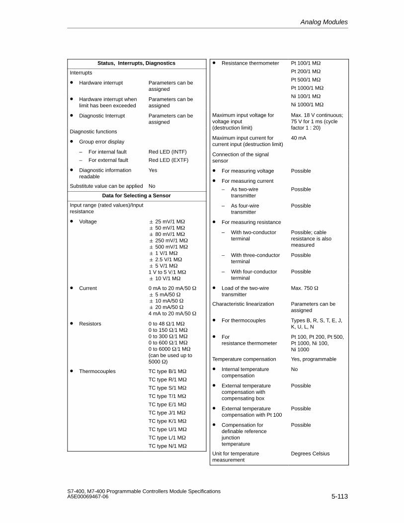
Analog Modules
5-113S7-400, M7-400 Programmable Controllers Module SpecificationsA5E00069467-06
Status, Interrupts, Diagnostics
Interrupts
• Hardware interrupt Parameters can beassigned
• Hardware interrupt whenlimit has been exceeded
Parameters can beassigned
• Diagnostic Interrupt Parameters can beassigned
Diagnostic functions
• Group error display
– For internal fault
– For external fault
Red LED (INTF)
Red LED (EXTF)
• Diagnostic information readable
Yes
Substitute value can be applied No
Data for Selecting a Sensor
Input range (rated values)/Inputresistance
• Voltage 25 mV/1 M 50 mV/1 M 80 mV/1 M 250 mV/1 M 500 mV/1 M 1 V/1 M 2.5 V/1 M 5 V/1 M1 V to 5 V1 M 10 V/1 M
• Current 0 mA to 20 mA50 5 mA/50 10 mA/50 20 mA/50 4 mA to 20 mA50
• Resistors 0 to 48 1 M0 to 150 1 M0 to 300 1 M0 to 600 1 M0 to 6000 1 M(can be used up to5000 )
• Thermocouples TC type B/1 M
TC type R/1 M
TC type S/1 M
TC type T/1 M
TC type E/1 M
TC type J/1 M
TC type K/1 M
TC type U/1 M
TC type L/1 M
TC type N/1 M
• Resistance thermometer Pt 100/1 M
Pt 200/1 M
Pt 500/1 M
Pt 1000/1 M
Ni 100/1 M
Ni 1000/1 M
Maximum input voltage forvoltage input (destruction limit)
Max. 18 V continuous;75 V for 1 ms (cyclefactor 1 : 20)
Maximum input current forcurrent input (destruction limit)
40 mA
Connection of the signalsensor
• For measuring voltage Possible
• For measuring current
– As two-wiretransmitter
Possible
– As four-wiretransmitter
Possible
• For measuring resistance
– With two-conductorterminal
Possible; cableresistance is alsomeasured
– With three-conductorterminal
Possible
– With four-conductorterminal
Possible
• Load of the two-wiretransmitter
Max. 750
Characteristic linearization Parameters can beassigned
• For thermocouples Types B, R, S, T, E, J,K, U, L, N
• For resistance thermometer
Pt 100, Pt 200, Pt 500,Pt 1000, Ni 100, Ni 1000
Temperature compensation Yes, programmable
• Internal temperaturecompensation
No
• External temperaturecompensation withcompensating box
Possible
• External temperaturecompensation with Pt 100
Possible
• Compensation fordefinable referencejunctiontemperature
Possible
Unit for temperaturemeasurement
Degrees Celsius
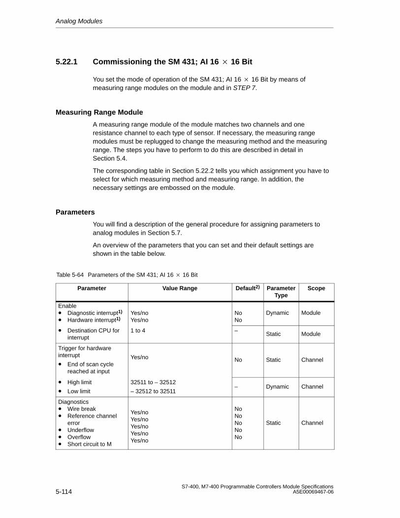
Analog Modules
5-114S7-400, M7-400 Programmable Controllers Module Specifications
A5E00069467-06
5.22.1 Commissioning the SM 431; AI 16 16 Bit
You set the mode of operation of the SM 431; AI 16 16 Bit by means ofmeasuring range modules on the module and in STEP 7.
Measuring Range Module
A measuring range module of the module matches two channels and oneresistance channel to each type of sensor. If necessary, the measuring rangemodules must be replugged to change the measuring method and the measuringrange. The steps you have to perform to do this are described in detail inSection 5.4.
The corresponding table in Section 5.22.2 tells you which assignment you have toselect for which measuring method and measuring range. In addition, thenecessary settings are embossed on the module.
Parameters
You will find a description of the general procedure for assigning parameters toanalog modules in Section 5.7.
An overview of the parameters that you can set and their default settings areshown in the table below.
Table 5-64 Parameters of the SM 431; AI 16 16 Bit
Parameter Value Range Default2) ParameterType
Scope
Enable• Diagnostic interrupt1)
• Hardware interrupt1)Yes/noYes/no
NoNo
Dynamic Module
• Destination CPU forinterrupt
1 to 4 –Static Module
Trigger for hardwareinterrupt
• End of scan cyclereached at input
Yes/no No Static Channel
• High limit
• Low limit
32511 to – 32512
– 32512 to 32511– Dynamic Channel
Diagnostics• Wire break• Reference channel
error• Underflow• Overflow• Short circuit to M
Yes/noYes/noYes/noYes/noYes/no
NoNoNoNoNo
Static Channel
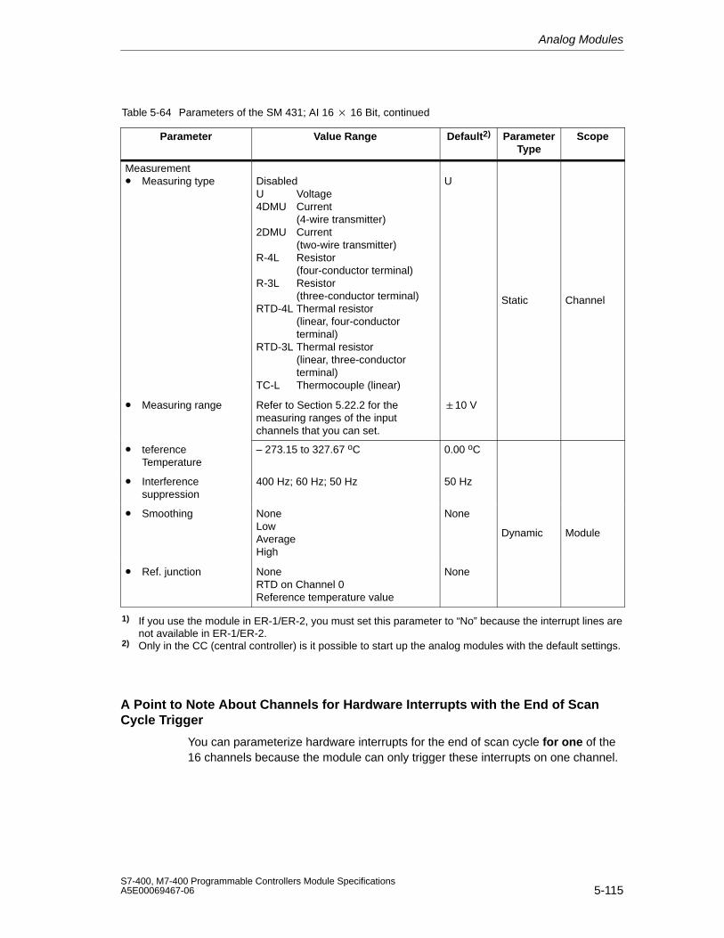
Analog Modules
5-115S7-400, M7-400 Programmable Controllers Module SpecificationsA5E00069467-06
Table 5-64 Parameters of the SM 431; AI 16 16 Bit, continued
Parameter ScopeParameterType
Default2)Value Range
Measurement• Measuring type Disabled
U Voltage4DMU Current
(4-wire transmitter)2DMU Current
(two-wire transmitter)R-4L Resistor
(four-conductor terminal)R-3L Resistor
(three-conductor terminal)RTD-4L Thermal resistor
(linear, four-conductor terminal)
RTD-3L Thermal resistor(linear, three-conductor terminal)
TC-L Thermocouple (linear)
U
Static Channel
• Measuring range Refer to Section 5.22.2 for themeasuring ranges of the inputchannels that you can set.
10 V
• teferenceTemperature
– 273.15 to 327.67 oC 0.00 oC
• Interferencesuppression
400 Hz; 60 Hz; 50 Hz 50 Hz
• Smoothing NoneLowAverageHigh
None
Dynamic Module
• Ref. junction NoneRTD on Channel 0Reference temperature value
None
1) If you use the module in ER-1/ER-2, you must set this parameter to “No” because the interrupt lines arenot available in ER-1/ER-2.
2) Only in the CC (central controller) is it possible to start up the analog modules with the default settings.
A Point to Note About Channels for Hardware Interrupts with the End of ScanCycle Trigger
You can parameterize hardware interrupts for the end of scan cycle for one of the16 channels because the module can only trigger these interrupts on one channel.
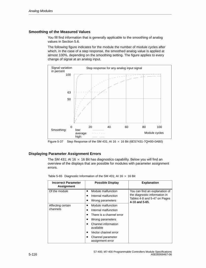
Analog Modules
5-116S7-400, M7-400 Programmable Controllers Module Specifications
A5E00069467-06
Smoothing of the Measured Values
You fill find information that is generally applicable to the smoothing of analogvalues in Section 5.6.
The following figure indicates for the module the number of module cycles afterwhich, in the case of a step response, the smoothed analog value is applied atalmost 100%, depending on the smoothing setting. The figure applies to everychange of signal at an analog input.
50
100
0
63
Smoothing: low:average:high:
Module cycles
Signal variationin percent
Step response for any analog input signal
60 8020 10040
Figure 5-37 Step Response of the SM 431; AI 16 16 Bit (6ES7431-7QH00-0AB0)
Displaying Parameter Assignment Errors
The SM 431; AI 16 16 Bit has diagnostics capability. Below you will find anoverview of the displays that are possible for modules with parameter assignmenterrors.
Table 5-65 Diagnostic Information of the SM 431; AI 16 16 Bit
Incorrect ParameterAssignment
Possible Display Explanation
Of the module • Module malfunction
• Internal malfunction
• Wrong parameters
You can find an explanation ofthe diagnostic information inTables 4-8 and 5-47 on Pages4-10 and 5-65.
Affecting certainchannels
• Module malfunction
• Internal malfunction
• There is a channel error
• Wrong parameters
• Channel informationavailable
• Vector channel error
• Channel parameterassignment error
4-10 and 5-65.
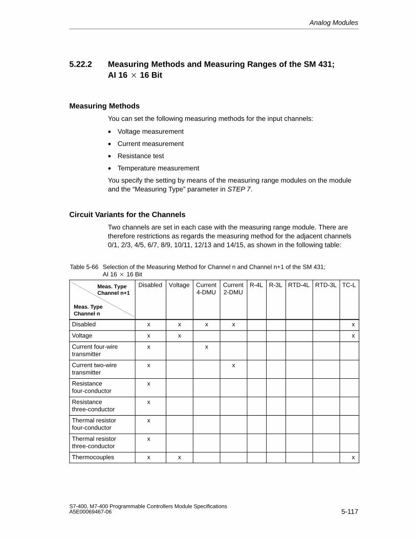
Analog Modules
5-117S7-400, M7-400 Programmable Controllers Module SpecificationsA5E00069467-06
5.22.2 Measuring Methods and Measuring Ranges of the SM 431;AI 16 16 Bit
Measuring Methods
You can set the following measuring methods for the input channels:
• Voltage measurement
• Current measurement
• Resistance test
• Temperature measurement
You specify the setting by means of the measuring range modules on the moduleand the “Measuring Type” parameter in STEP 7.
Circuit Variants for the Channels
Two channels are set in each case with the measuring range module. There aretherefore restrictions as regards the measuring method for the adjacent channels0/1, 2/3, 4/5, 6/7, 8/9, 10/11, 12/13 and 14/15, as shown in the following table:
Table 5-66 Selection of the Measuring Method for Channel n and Channel n+1 of the SM 431; AI 16 16 Bit
Meas. TypeChannel n+1
Meas. TypeChannel n
Disabled Voltage Current4-DMU
Current2-DMU
R-4L R-3L RTD-4L RTD-3L TC-L
Disabled x x x x x
Voltage x x x
Current four-wiretransmitter
x x
Current two-wiretransmitter
x x
Resistancefour-conductor
x
Resistancethree-conductor
x
Thermal resistorfour-conductor
x
Thermal resistorthree-conductor
x
Thermocouples x x x
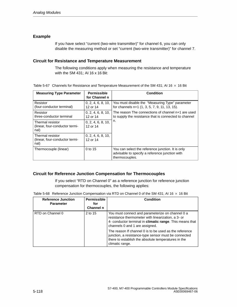
Analog Modules
5-118S7-400, M7-400 Programmable Controllers Module Specifications
A5E00069467-06
Example
If you have select “current (two-wire transmitter)” for channel 6, you can onlydisable the measuring method or set “current (two-wire transmitter)” for channel 7.
Circuit for Resistance and Temperature Measurement
The following conditions apply when measuring the resistance and temperaturewith the SM 431; AI 16 x 16 Bit:
Table 5-67 Channels for Resistance and Temperature Measurement of the SM 431; AI 16 16 Bit
Measuring Type Parameter Permissiblefor Channel n
Condition
Resistor (four-conductor terminal)
0, 2, 4, 6, 8, 10,12 or 14
You must disable the “Measuring Type” parameterfor channels n+1 (1, 3, 5, 7, 9, 11, 13, 15).
Resistor three-conductor terminal
0, 2, 4, 6, 8, 10,12 or 14
The reason The connections of channel n+1 are usedto supply the resistance that is connected to channel
Thermal resistor(linear, four-conductor termi-nal)
0, 2, 4, 6, 8, 10,12 or 14
n.
Thermal resistor(linear, four-conductor termi-nal)
0, 2, 4, 6, 8, 10,12 or 14
Thermocouple (linear) 0 to 15 You can select the reference junction. It is onlyadvisable to specify a reference junction withthermocouples.
Circuit for Reference Junction Compensation for Thermocouples
If you select “RTD on Channel 0” as a reference junction for reference junctioncompensation for thermocouples, the following applies:
Table 5-68 Reference Junction Compensation via RTD on Channel 0 of the SM 431; AI 16 16 Bit
Reference JunctionParameter
Permissiblefor
Channel n
Condition
RTD on Channel 0 2 to 15 You must connect and parameterize on channel 0 aresistance thermometer with linearization, a 3- or4- conductor terminal in climatic range. This means thatchannels 0 and 1 are assigned.
The reason If channel 0 is to be used as the referencejunction, a resistance-type sensor must be connectedthere to establish the absolute temperatures in theclimatic range.
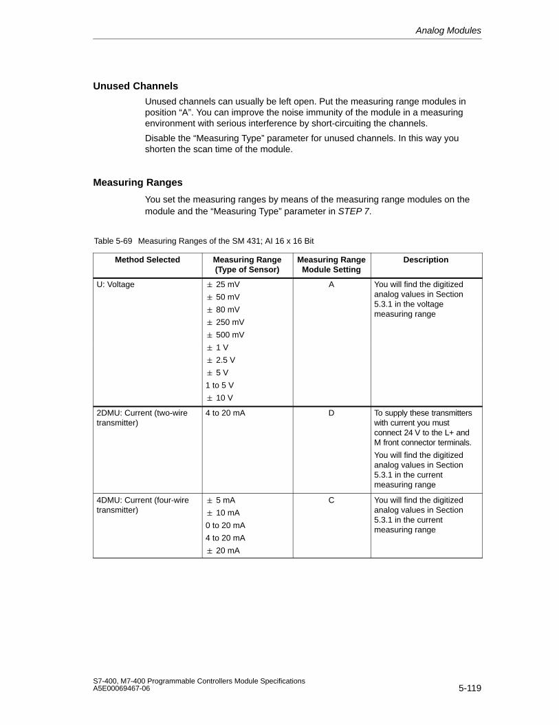
Analog Modules
5-119S7-400, M7-400 Programmable Controllers Module SpecificationsA5E00069467-06
Unused Channels
Unused channels can usually be left open. Put the measuring range modules inposition “A”. You can improve the noise immunity of the module in a measuringenvironment with serious interference by short-circuiting the channels.
Disable the “Measuring Type” parameter for unused channels. In this way youshorten the scan time of the module.
Measuring Ranges
You set the measuring ranges by means of the measuring range modules on themodule and the “Measuring Type” parameter in STEP 7.
Table 5-69 Measuring Ranges of the SM 431; AI 16 x 16 Bit
Method Selected Measuring Range(Type of Sensor)
Measuring RangeModule Setting
Description
U: Voltage 25 mV
50 mV
80 mV
250 mV
500 mV
A You will find the digitizedanalog values in Section5.3.1 in the voltagemeasuring range
1 V
2.5 V
5 V
1 to 5 V
10 V
2DMU: Current (two-wiretransmitter)
4 to 20 mA D To supply these transmitterswith current you mustconnect 24 V to the L+ andM front connector terminals.
You will find the digitizedanalog values in Section5.3.1 in the currentmeasuring range
4DMU: Current (four-wiretransmitter)
5 mA
10 mA
0 to 20 mA
4 to 20 mA
20 mA
C You will find the digitizedanalog values in Section5.3.1 in the currentmeasuring range
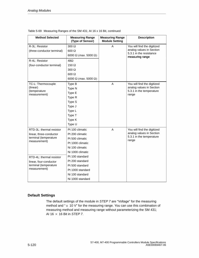
Analog Modules
5-120S7-400, M7-400 Programmable Controllers Module Specifications
A5E00069467-06
Table 5-69 Measuring Ranges of the SM 431; AI 16 x 16 Bit, continued
Method Selected DescriptionMeasuring RangeModule Setting
Measuring Range(Type of Sensor)
R-3L: Resistor
(three-conductor terminal)
300
600
6000 max. 5000
A You will find the digitizedanalog values in Section5.3.1 in the resistancemeasuring range
R-4L: Resistor
(four-conductor terminal)
48
150
300
600
6000 max. 5000
measuring range
TC-L: Thermocouple(linear)(temperaturemeasurement)
Type B
Type N
Type E
Type R
Type S
Type J
Type L
Type T
Type K
Type U
A You will find the digitizedanalog values in Section5.3.1 in the temperaturerange
RTD-3L: thermal resistor
linear, three-conductorterminal (temperaturemeasurement)
Pt 100 climatic
Pt 200 climatic
Pt 500 climatic
Pt 1000 climatic
Ni 100 climatic
Ni 1000 climatic
A You will find the digitizedanalog values in Section5.3.1 in the temperaturerange
RTD-4L: thermal resistor
linear, four-conductorterminal (temperaturemeasurement)
Pt 100 standard
Pt 200 standard
Pt 500 standard
Pt 1000 standard
Ni 100 standard
Ni 1000 standard
Default Settings
The default settings of the module in STEP 7 are “Voltage” for the measuringmethod and “ 10 V” for the measuring range. You can use this combination ofmeasuring method and measuring range without parameterizing the SM 431;AI 16 16 Bit in STEP 7.
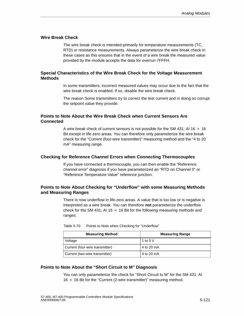
Analog Modules
5-121S7-400, M7-400 Programmable Controllers Module SpecificationsA5E00069467-06
Wire Break Check
The wire break check is intended primarily for temperature measurements (TC,RTD) or resistance measurements. Always parameterize the wire break check inthese cases as this ensures that in the event of a wire break the measured valueprovided by the module accepts the data for overrun 7FFFH.
Special Characteristics of the Wire Break Check for the Voltage MeasurementMethods
In some transmitters, incorrect measured values may occur due to the fact that thewire break check is enabled. If so, disable the wire break check.
The reason Some transmitters try to correct the test current and in doing so corruptthe setpoint value they provide.
Points to Note About the Wire Break Check when Current Sensors AreConnected
A wire break check of current sensors is not possible for the SM 431; AI 16 16Bit except in life-zero areas. You can therefore only parameterize the wire breakcheck for the “Current (four-wire transmitter)” measuring method and the “4 to 20mA” measuring range.
Checking for Reference Channel Errors when Connecting Thermocouples
If you have connected a thermocouple, you can then enable the “Referencechannel error” diagnosis if you have parameterized an “RTD on Channel 0” or“Reference Temperature Value” reference junction.
Points to Note About Checking for “Underflow” with some Measuring Methodsand Measuring Ranges
There is now underflow in life-zero areas. A value that is too low or is negative isinterpreted as a wire break. You can therefore not parameterize the underflowcheck for the SM 431; AI 16 16 Bit for the following measuring methods andranges:
Table 5-70 Points to Note when Checking for “Underflow”
Measuring Method Measuring Range
Voltage 1 to 5 V
Current (four-wire transmitter) 4 to 20 mA
Current (two-wire transmitter) 4 to 20 mA
Points to Note About the “Short Circuit to M” Diagnosis
You can only parameterize the check for “Short Circuit to M” for the SM 431; AI16 16 Bit for the “Current (2-wire transmitter)” measuring method.
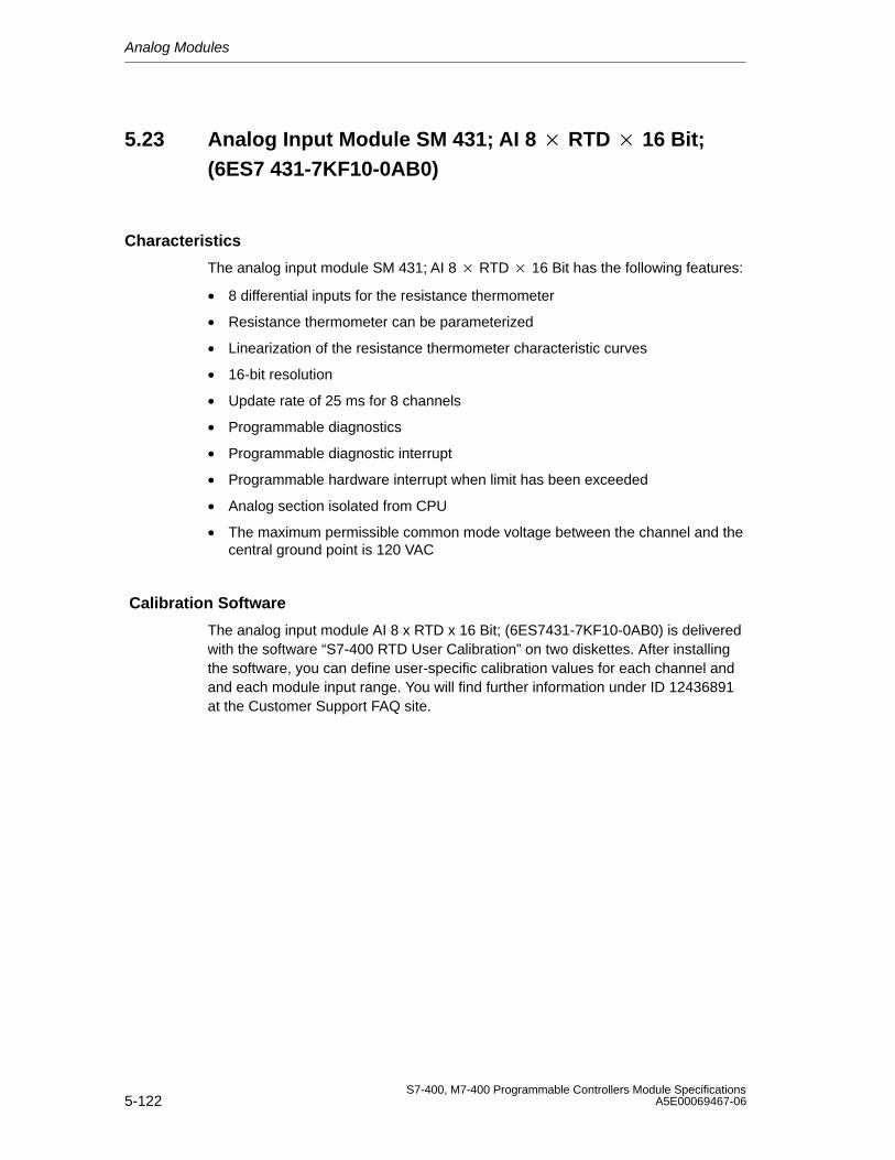
Analog Modules
5-122S7-400, M7-400 Programmable Controllers Module Specifications
A5E00069467-06
5.23 Analog Input Module SM 431; AI 8 RTD 16 Bit;(6ES7 431-7KF10-0AB0)
Characteristics
The analog input module SM 431; AI 8 RTD 16 Bit has the following features:
• 8 differential inputs for the resistance thermometer
• Resistance thermometer can be parameterized
• Linearization of the resistance thermometer characteristic curves
• 16-bit resolution
• Update rate of 25 ms for 8 channels
• Programmable diagnostics
• Programmable diagnostic interrupt
• Programmable hardware interrupt when limit has been exceeded
• Analog section isolated from CPU
• The maximum permissible common mode voltage between the channel and thecentral ground point is 120 VAC
Calibration Software
The analog input module AI 8 x RTD x 16 Bit; (6ES7431-7KF10-0AB0) is deliveredwith the software “S7-400 RTD User Calibration” on two diskettes. After installingthe software, you can define user-specific calibration values for each channel andand each module input range. You will find further information under ID 12436891at the Customer Support FAQ site.
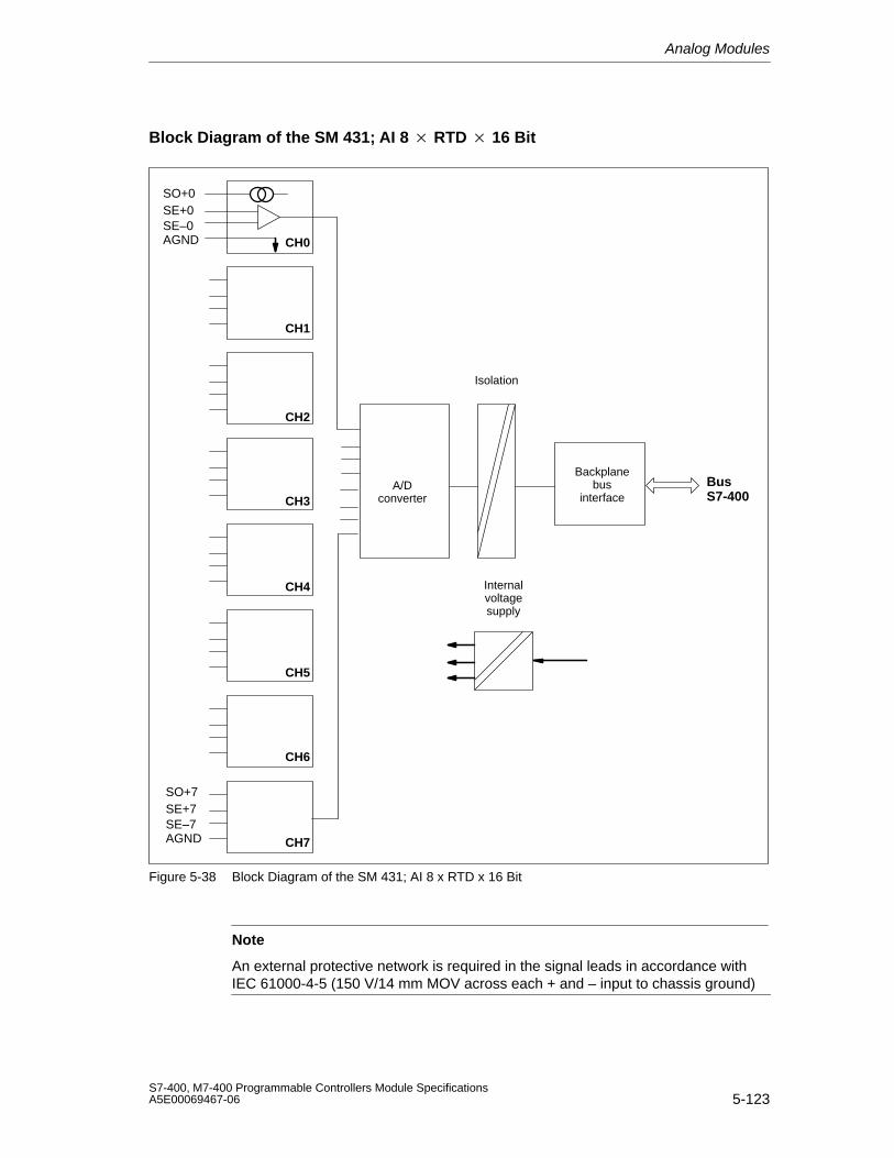
Analog Modules
5-123S7-400, M7-400 Programmable Controllers Module SpecificationsA5E00069467-06
Block Diagram of the SM 431; AI 8 RTD 16 Bit
Backplanebus
interfaceBusS7-400
SO+0SE+0SE–0AGND
SO+7SE+7SE–7AGND
CH0
CH1
CH2
CH3
CH4
CH5
CH6
CH7
A/Dconverter
Isolation
Internalvoltagesupply
Figure 5-38 Block Diagram of the SM 431; AI 8 x RTD x 16 Bit
Note
An external protective network is required in the signal leads in accordance withIEC 61000-4-5 (150 V/14 mm MOV across each + and – input to chassis ground)
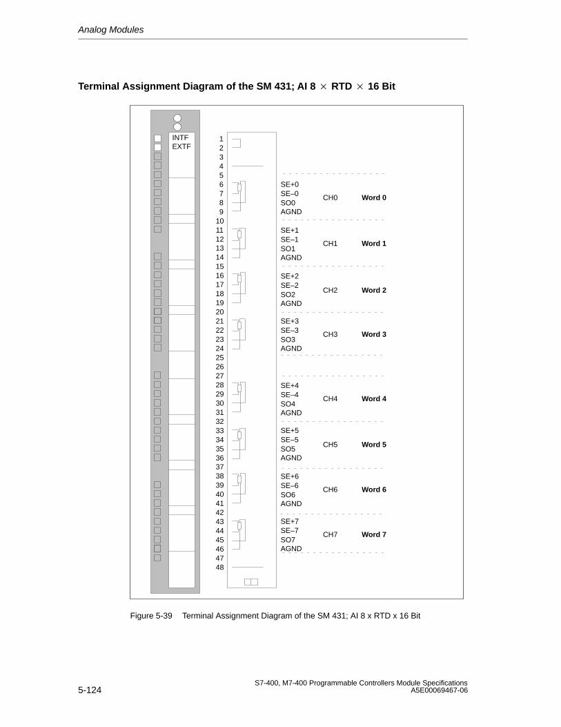
Analog Modules
5-124S7-400, M7-400 Programmable Controllers Module Specifications
A5E00069467-06
Terminal Assignment Diagram of the SM 431; AI 8 RTD 16 Bit
SO0CH0
CH1
CH2
CH3
CH4
CH5
CH6
CH7
SE+0SE–0
AGND
293031323334353637
39404142434445464748
38
123456789
10111213141516171819202122232425262728
INTFEXTF
Word 0
Word 2
Word 4
Word 6
Word 1
Word 3
Word 5
Word 7
SO1
SE+1SE–1
AGND
SO2
SE+2SE–2
AGND
SO3
SE+3SE–3
AGND
SO4
SE+4SE–4
AGND
SO5
SE+5SE–5
AGND
SO6
SE+6SE–6
AGND
SO7
SE+7SE–7
AGND
Figure 5-39 Terminal Assignment Diagram of the SM 431; AI 8 x RTD x 16 Bit
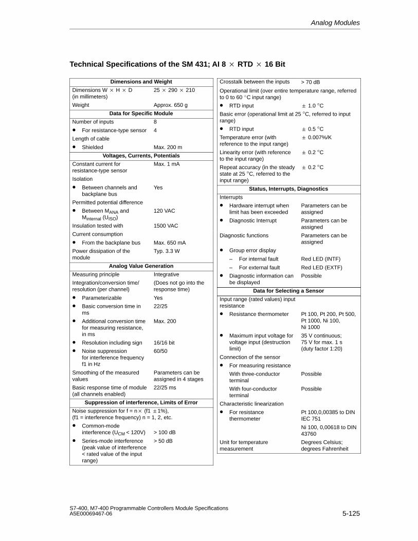
Analog Modules
5-125S7-400, M7-400 Programmable Controllers Module SpecificationsA5E00069467-06
Technical Specifications of the SM 431; AI 8 RTD 16 Bit
Dimensions and Weight
Dimensions W H D(in millimeters)
25 290 210
Weight Approx. 650 g
Data for Specific Module
Number of inputs
• For resistance-type sensor
8
4
Length of cable
• Shielded Max. 200 m
Voltages, Currents, Potentials
Constant current forresistance-type sensor
Max. 1 mA
Isolation
• Between channels andbackplane bus
Yes
Permitted potential difference
• Between MANA andMinternal (UISO)
120 VAC
Insulation tested with 1500 VAC
Current consumption
• From the backplane bus Max. 650 mA
Power dissipation of themodule
Typ. 3.3 W
Analog Value Generation
Measuring principle Integrative
Integration/conversion time/resolution (per channel)
• Parameterizable
(Does not go into theresponse time)
Yes
• Basic conversion time inms
22/25
• Additional conversion timefor measuring resistance,in ms
Max. 200
• Resolution including sign 16/16 bit
• Noise suppressionfor interference frequencyf1 in Hz
60/50
Smoothing of the measuredvalues
Parameters can beassigned in 4 stages
Basic response time of module(all channels enabled)
22/25 ms
Suppression of interference, Limits of Error
Noise suppression for f = n (f1 1%), (f1 = interference frequency) n = 1, 2, etc.
• Common-modeinterference (UCM < 120V)
• Series-mode interference (peak value of interference< rated value of the inputrange)
> 100 dB
> 50 dB
Crosstalk between the inputs > 70 dB
Operational limit (over entire temperature range, referredto 0 to 60 C input range)
• RTD input 1.0 °C
Basic error (operational limit at 25 °C, referred to inputrange)
• RTD input 0.5 °C
Temperature error (withreference to the input range)
0.007%/K
Linearity error (with referenceto the input range)
0.2 °C
Repeat accuracy (in the steadystate at 25 °C, referred to theinput range)
0.2 °C
Status, Interrupts, Diagnostics
Interrupts
• Hardware interrupt whenlimit has been exceeded
Parameters can beassigned
• Diagnostic Interrupt Parameters can beassigned
Diagnostic functions Parameters can beassigned
• Group error display
– For internal fault
– For external fault
Red LED (INTF)
Red LED (EXTF)
• Diagnostic information canbe displayed
Possible
Data for Selecting a Sensor
Input range (rated values) inputresistance
• Resistance thermometer Pt 100, Pt 200, Pt 500,Pt 1000, Ni 100,Ni 1000
• Maximum input voltage forvoltage input (destructionlimit)
35 V continuous; 75 V for max. 1 s (duty factor 1:20)
Connection of the sensor
• For measuring resistance
With three-conductorterminal
Possible
With four-conductorterminal
Possible
Characteristic linearization
• For resistancethermometer
Pt 100,0,00385 to DINIEC 751
Ni 100, 0,00618 to DIN43760
Unit for temperaturemeasurement
Degrees Celsius;degrees Fahrenheit
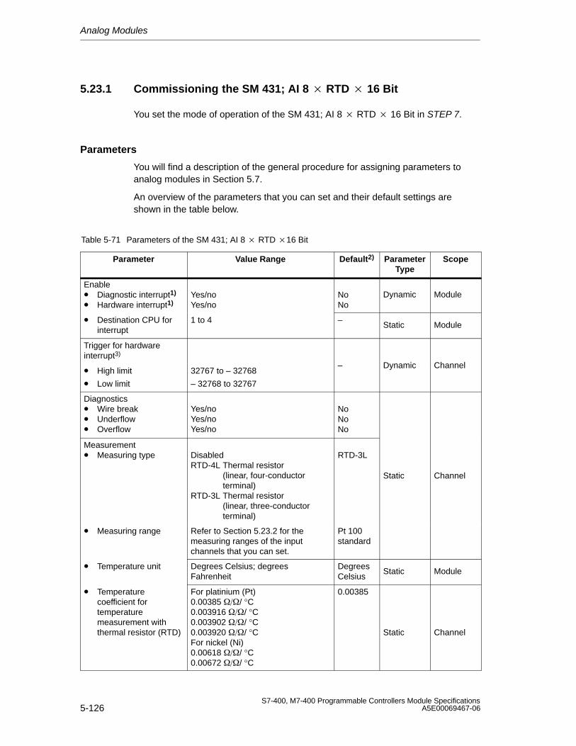
Analog Modules
5-126S7-400, M7-400 Programmable Controllers Module Specifications
A5E00069467-06
5.23.1 Commissioning the SM 431; AI 8 RTD 16 Bit
You set the mode of operation of the SM 431; AI 8 RTD 16 Bit in STEP 7.
Parameters
You will find a description of the general procedure for assigning parameters toanalog modules in Section 5.7.
An overview of the parameters that you can set and their default settings areshown in the table below.
Table 5-71 Parameters of the SM 431; AI 8 RTD 16 Bit
Parameter Value Range Default2) ParameterType
Scope
Enable• Diagnostic interrupt1)
• Hardware interrupt1)Yes/noYes/no
NoNo
Dynamic Module
• Destination CPU forinterrupt
1 to 4 –Static Module
Trigger for hardwareinterrupt3)
• High limit
• Low limit
32767 to – 32768
– 32768 to 32767
– Dynamic Channel
Diagnostics• Wire break• Underflow• Overflow
Yes/noYes/noYes/no
NoNoNo
Measurement• Measuring type Disabled
RTD-4L Thermal resistor(linear, four-conductor terminal)
RTD-3L Thermal resistor(linear, three-conductor terminal)
RTD-3L
Static Channel
• Measuring range Refer to Section 5.23.2 for themeasuring ranges of the inputchannels that you can set.
Pt 100standard
• Temperature unit Degrees Celsius; degreesFahrenheit
DegreesCelsius
Static Module
• Temperaturecoefficient fortemperaturemeasurement withthermal resistor (RTD)
For platinium (Pt)0.00385 / °C0.003916 / °C0.003902 / °C0.003920 / °CFor nickel (Ni)0.00618 / °C0.00672 / °C
0.00385
Static Channel
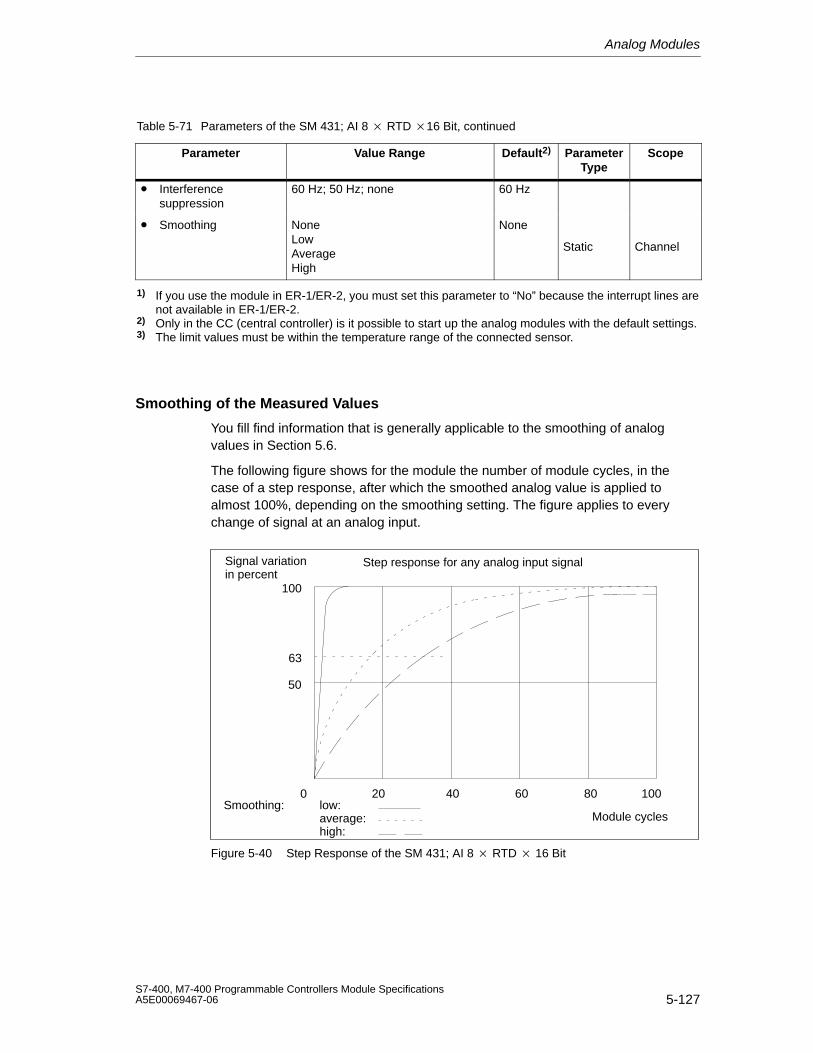
Analog Modules
5-127S7-400, M7-400 Programmable Controllers Module SpecificationsA5E00069467-06
Table 5-71 Parameters of the SM 431; AI 8 RTD 16 Bit, continued
Parameter ScopeParameterType
Default2)Value Range
• Interferencesuppression
60 Hz; 50 Hz; none 60 Hz
• Smoothing NoneLowAverageHigh
None
Static Channel
1) If you use the module in ER-1/ER-2, you must set this parameter to “No” because the interrupt lines arenot available in ER-1/ER-2.
2) Only in the CC (central controller) is it possible to start up the analog modules with the default settings.3) The limit values must be within the temperature range of the connected sensor.
Smoothing of the Measured Values
You fill find information that is generally applicable to the smoothing of analogvalues in Section 5.6.
The following figure shows for the module the number of module cycles, in thecase of a step response, after which the smoothed analog value is applied toalmost 100%, depending on the smoothing setting. The figure applies to everychange of signal at an analog input.
50
100
0
63
Smoothing: low:average:high:
Module cycles
Signal variationin percent
Step response for any analog input signal
60 8020 10040
Figure 5-40 Step Response of the SM 431; AI 8 RTD 16 Bit
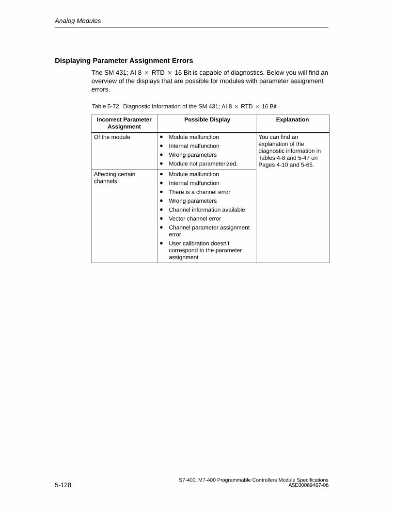
Analog Modules
5-128S7-400, M7-400 Programmable Controllers Module Specifications
A5E00069467-06
Displaying Parameter Assignment Errors
The SM 431; AI 8 RTD 16 Bit is capable of diagnostics. Below you will find anoverview of the displays that are possible for modules with parameter assignmenterrors.
Table 5-72 Diagnostic Information of the SM 431; AI 8 RTD 16 Bit
Incorrect ParameterAssignment
Possible Display Explanation
Of the module • Module malfunction
• Internal malfunction
• Wrong parameters
• Module not parameterized.
You can find anexplanation of thediagnostic information inTables 4-8 and 5-47 onPages 4-10 and 5-65.
Affecting certainchannels
• Module malfunction
• Internal malfunction
• There is a channel error
• Wrong parameters
• Channel information available
• Vector channel error
• Channel parameter assignmenterror
• User calibration doesn’tcorrespond to the parameterassignment
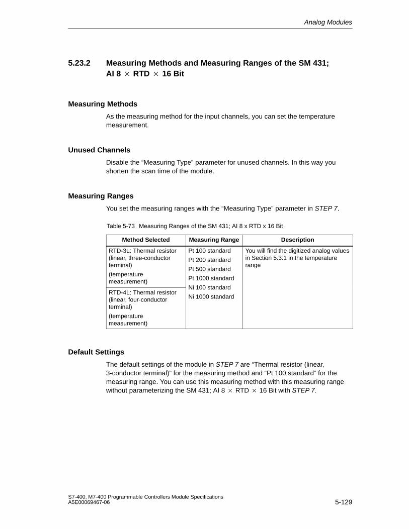
Analog Modules
5-129S7-400, M7-400 Programmable Controllers Module SpecificationsA5E00069467-06
5.23.2 Measuring Methods and Measuring Ranges of the SM 431;AI 8 RTD 16 Bit
Measuring Methods
As the measuring method for the input channels, you can set the temperaturemeasurement.
Unused Channels
Disable the “Measuring Type” parameter for unused channels. In this way youshorten the scan time of the module.
Measuring Ranges
You set the measuring ranges with the “Measuring Type” parameter in STEP 7.
Table 5-73 Measuring Ranges of the SM 431; AI 8 x RTD x 16 Bit
Method Selected Measuring Range Description
RTD-3L: Thermal resistor(linear, three-conductorterminal)
(temperaturemeasurement)
Pt 100 standard
Pt 200 standard
Pt 500 standard
Pt 1000 standard
You will find the digitized analog valuesin Section 5.3.1 in the temperaturerange
RTD-4L: Thermal resistor(linear, four-conductorterminal)
(temperaturemeasurement)
Ni 100 standard
Ni 1000 standard
Default Settings
The default settings of the module in STEP 7 are “Thermal resistor (linear,3-conductor terminal)” for the measuring method and “Pt 100 standard” for themeasuring range. You can use this measuring method with this measuring rangewithout parameterizing the SM 431; AI 8 RTD 16 Bit with STEP 7.
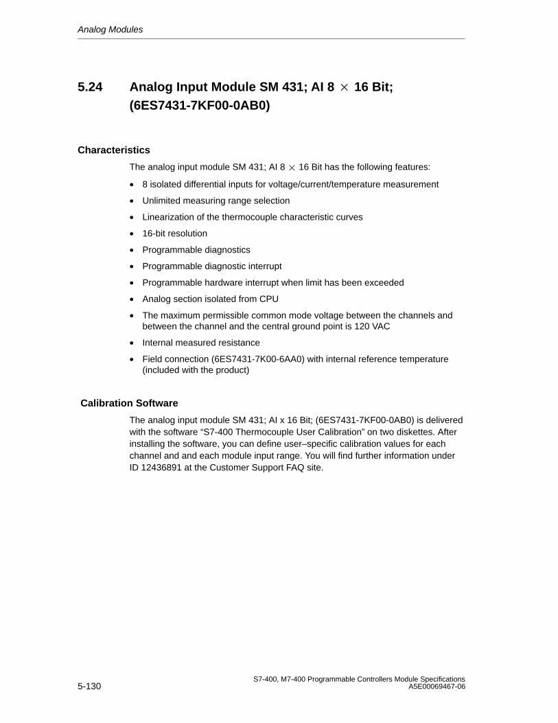
Analog Modules
5-130S7-400, M7-400 Programmable Controllers Module Specifications
A5E00069467-06
5.24 Analog Input Module SM 431; AI 8 16 Bit;(6ES7431-7KF00-0AB0)
Characteristics
The analog input module SM 431; AI 8 16 Bit has the following features:
• 8 isolated differential inputs for voltage/current/temperature measurement
• Unlimited measuring range selection
• Linearization of the thermocouple characteristic curves
• 16-bit resolution
• Programmable diagnostics
• Programmable diagnostic interrupt
• Programmable hardware interrupt when limit has been exceeded
• Analog section isolated from CPU
• The maximum permissible common mode voltage between the channels andbetween the channel and the central ground point is 120 VAC
• Internal measured resistance
• Field connection (6ES7431-7K00-6AA0) with internal reference temperature(included with the product)
Calibration Software
The analog input module SM 431; AI x 16 Bit; (6ES7431-7KF00-0AB0) is deliveredwith the software “S7-400 Thermocouple User Calibration” on two diskettes. Afterinstalling the software, you can define user–specific calibration values for eachchannel and and each module input range. You will find further information underID 12436891 at the Customer Support FAQ site.
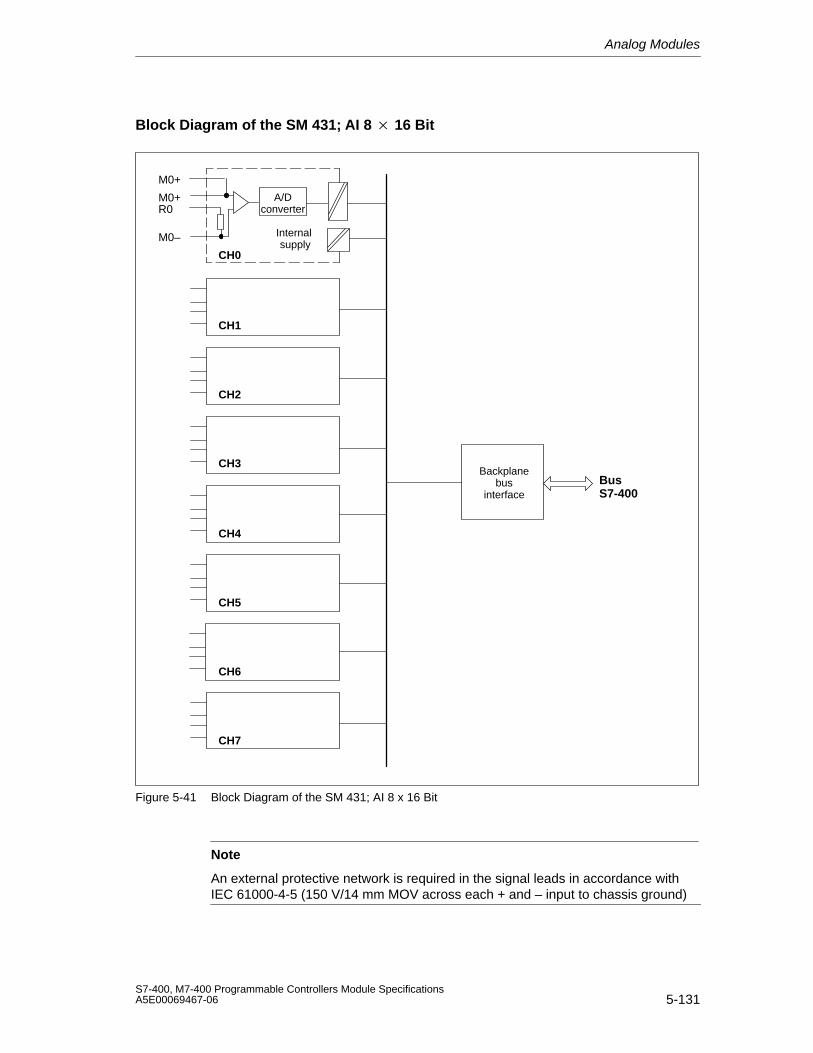
Analog Modules
5-131S7-400, M7-400 Programmable Controllers Module SpecificationsA5E00069467-06
Block Diagram of the SM 431; AI 8 16 Bit
Backplanebus
interfaceBusS7-400
M0+
M0+R0
M0–
CH1
CH2
CH3
CH4
CH5
CH6
CH7
CH0
A/Dconverter
Internal supply
Figure 5-41 Block Diagram of the SM 431; AI 8 x 16 Bit
Note
An external protective network is required in the signal leads in accordance withIEC 61000-4-5 (150 V/14 mm MOV across each + and – input to chassis ground)
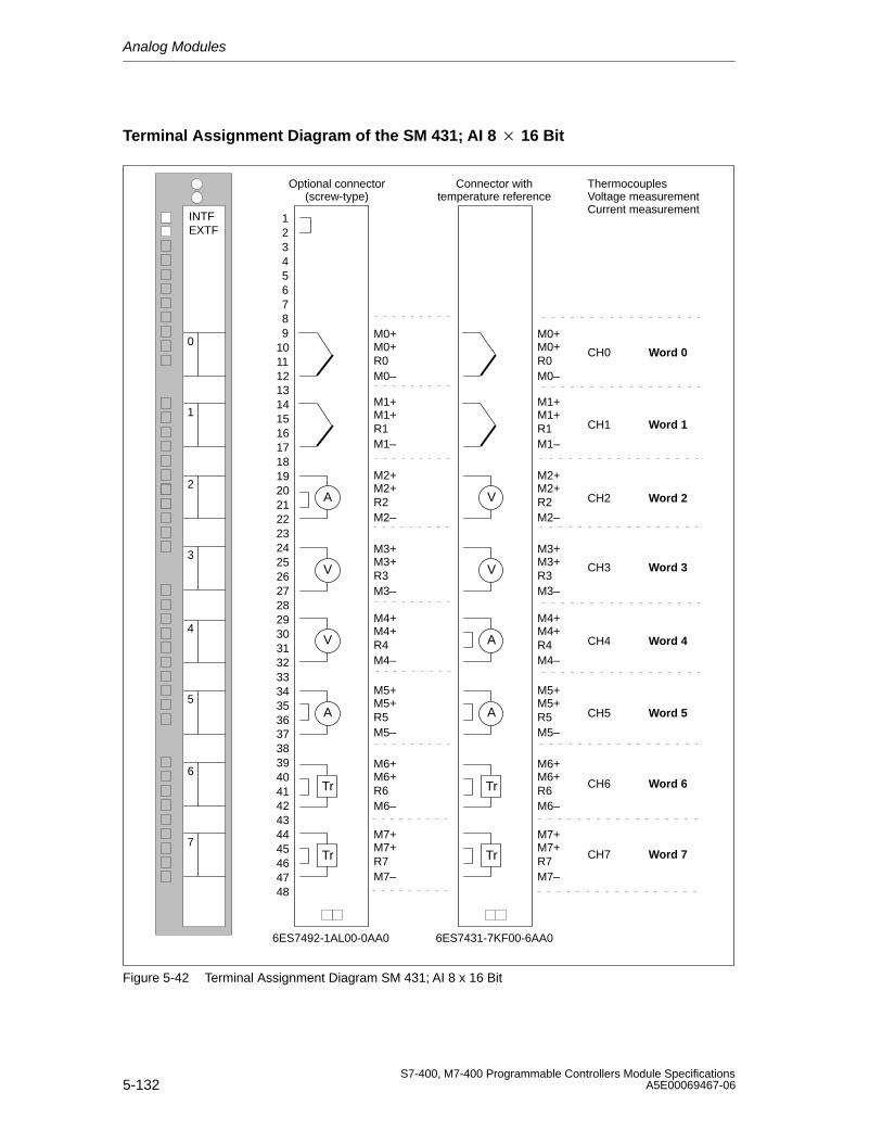
Analog Modules
5-132S7-400, M7-400 Programmable Controllers Module Specifications
A5E00069467-06
Terminal Assignment Diagram of the SM 431; AI 8 16 Bit
R0CH0
CH1
CH2
CH3
CH4
CH5
CH6
CH7
M0+M0+
M0–
INTFEXTF
Word 0
Word 2
Word 4
Word 6
Word 1
Word 3
Word 5
Word 7
V
A
V
A
Tr
Tr
R1
M1+M1+
M1–
R2
M2+M2+
M2–
R3
M3+M3+
M3–
R4
M4+M4+
M4–
R5
M5+M5+
M5–
R6
M6+M6+
M6–
R7
M7+M7+
M7–
ThermocouplesVoltage measurementCurrent measurement
0
1
2
3
4
5
6
7
R0
M0+M0+
M0–
A
A
V
V
Tr
Tr
R1
M1+M1+
M1–
R2
M2+M2+
M2–
R3
M3+M3+
M3–
R4
M4+M4+
M4–
R5
M5+M5+
M5–
R6
M6+M6+
M6–
R7
M7+M7+
M7–
293031323334353637
39404142434445464748
38
123456789
10111213141516171819202122232425262728
Optional connector(screw-type)
Connector withtemperature reference
6ES7431-7KF00-6AA06ES7492-1AL00-0AA0
Figure 5-42 Terminal Assignment Diagram SM 431; AI 8 x 16 Bit
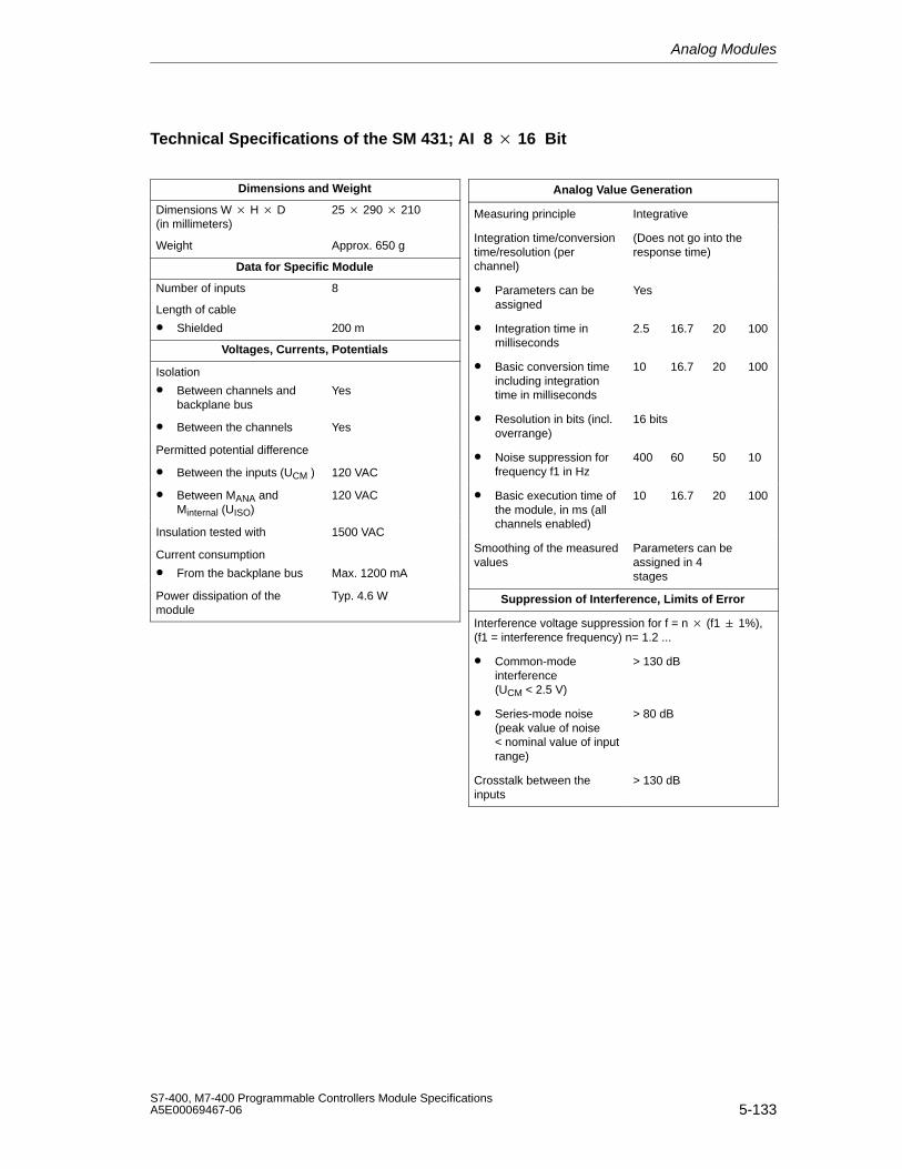
Analog Modules
5-133S7-400, M7-400 Programmable Controllers Module SpecificationsA5E00069467-06
Technical Specifications of the SM 431; AI 8 16 Bit
Dimensions and Weight
Dimensions W H D(in millimeters)
25 290 210
Weight Approx. 650 g
Data for Specific Module
Number of inputs 8
Length of cable
• Shielded 200 m
Voltages, Currents, Potentials
Isolation
• Between channels andbackplane bus
Yes
• Between the channels Yes
Permitted potential difference
• Between the inputs (UCM ) 120 VAC
• Between MANA andMinternal (UISO)
120 VAC
Insulation tested with 1500 VAC
Current consumption
• From the backplane bus Max. 1200 mA
Power dissipation of themodule
Typ. 4.6 W
Analog Value Generation
Measuring principle Integrative
Integration time/conversiontime/resolution (perchannel)
(Does not go into theresponse time)
• Parameters can beassigned
Yes
• Integration time inmilliseconds
2.5 16.7 20 100
• Basic conversion timeincluding integrationtime in milliseconds
10 16.7 20 100
• Resolution in bits (incl.overrange)
16 bits
• Noise suppression forfrequency f1 in Hz
400 60 50 10
• Basic execution time ofthe module, in ms (allchannels enabled)
10 16.7 20 100
Smoothing of the measuredvalues
Parameters can beassigned in 4stages
Suppression of Interference, Limits of Error
Interference voltage suppression for f = n (f1 1%),(f1 = interference frequency) n= 1.2 ...
• Common-modeinterference(UCM < 2.5 V)
> 130 dB
• Series-mode noise(peak value of noise < nominal value of inputrange)
> 80 dB
Crosstalk between theinputs
> 130 dB
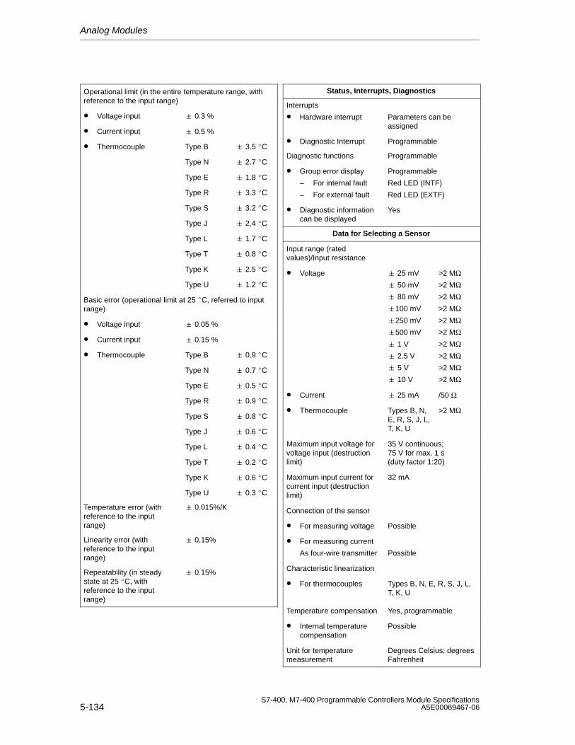
Analog Modules
5-134S7-400, M7-400 Programmable Controllers Module Specifications
A5E00069467-06
Operational limit (in the entire temperature range, withreference to the input range)
• Voltage input 0.3 %
• Current input 0.5 %
• Thermocouple Type B 3.5 C
Type N 2.7 C
Type E 1.8 C
Type R 3.3 C
Type S 3.2 C
Type J 2.4 C
Type L 1.7 C
Type T 0.8 C
Type K 2.5 C
Type U 1.2 C
Basic error (operational limit at 25 C, referred to inputrange)
• Voltage input 0.05 %
• Current input 0.15 %
• Thermocouple Type B 0.9 C
Type N 0.7 C
Type E 0.5 C
Type R 0.9 C
Type S 0.8 C
Type J 0.6 C
Type L 0.4 C
Type T 0.2 C
Type K 0.6 C
Type U 0.3 C
Temperature error (withreference to the inputrange)
0.015%/K
Linearity error (withreference to the inputrange)
0.15%
Repeatability (in steadystate at 25 C, withreference to the inputrange)
0.15%
Status, Interrupts, Diagnostics
Interrupts
• Hardware interrupt Parameters can beassigned
• Diagnostic Interrupt Programmable
Diagnostic functions Programmable
• Group error display
– For internal fault
– For external fault
Programmable
Red LED (INTF)
Red LED (EXTF)
• Diagnostic informationcan be displayed
Yes
Data for Selecting a Sensor
Input range (ratedvalues)/Input resistance
• Voltage 25 mV
50 mV
80 mV
100 mV
250 mV
500 mV
1 V
2.5 V
5 V
10 V
>2 MΩ>2 MΩ>2 MΩ>2 MΩ>2 MΩ>2 MΩ>2 MΩ>2 MΩ>2 MΩ>2 MΩ
• Current 25 mA /50 Ω
• Thermocouple Types B, N,E, R, S, J, L,T, K, U
>2 MΩ
Maximum input voltage forvoltage input (destructionlimit)
35 V continuous; 75 V for max. 1 s (duty factor 1:20)
Maximum input current forcurrent input (destructionlimit)
32 mA
Connection of the sensor
• For measuring voltage Possible
• For measuring current
As four-wire transmitter Possible
Characteristic linearization
• For thermocouples Types B, N, E, R, S, J, L,T, K, U
Temperature compensation Yes, programmable
• Internal temperaturecompensation
Possible
Unit for temperaturemeasurement
Degrees Celsius; degreesFahrenheit
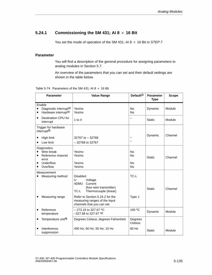
Analog Modules
5-135S7-400, M7-400 Programmable Controllers Module SpecificationsA5E00069467-06
5.24.1 Commissioning the SM 431; AI 8 16 Bit
You set the mode of operation of the SM 431; AI 8 16 Bit in STEP 7.
Parameter
You will find a description of the general procedure for assigning parameters toanalog modules in Section 5.7.
An overview of the parameters that you can set and their default settings areshown in the table below.
Table 5-74 Parameters of the SM 431; AI 8 16 Bit
Parameter Value Range Default2) ParameterType
Scope
Enable• Diagnostic interrupt1)
• Hardware interrupt1)Yes/noYes/no
NoNo
Dynamic Module
• Destination CPU forinterrupt
1 to 4–
Static Module
Trigger for hardwareinterrupt3)
• High limit
• Low limit
32767 to – 32768
– 32768 to 32767
––
Dynamic Channel
Diagnostics• Wire break• Reference channel
error• Underflow• Overflow
Yes/noYes/no
Yes/noYes/no
NoNo
NoNo
Static Channel
Measurement• Measuring method Disabled
U Voltage4DMU Current
(four-wire transmitter)TC-L Thermocouple (linear)
TC-L
Static Channel
• Measuring range Refer to Section 5.24.2 for themeasuring ranges of the inputchannels that you can set.
Type J
• Referencetemperature
– 273.15 to 327.67 oC–327.68 to 327.67 oF
100 oCDynamic Module
• Temperature unit4) Degrees Celsius; degrees Fahrenheit DegreesCelsius
• Interferencesuppression
400 Hz; 60 Hz; 50 Hz; 10 Hz 60 HzStatic Module
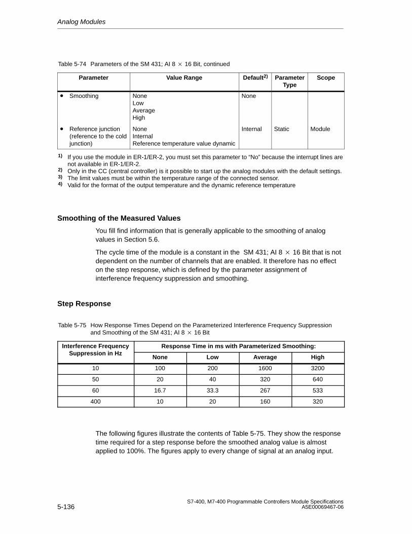
Analog Modules
5-136S7-400, M7-400 Programmable Controllers Module Specifications
A5E00069467-06
Table 5-74 Parameters of the SM 431; AI 8 16 Bit, continued
Parameter ScopeParameterType
Default2)Value Range
• Smoothing NoneLowAverageHigh
None
• Reference junction (reference to the coldjunction)
NoneInternalReference temperature value dynamic
Internal Static Module
1) If you use the module in ER-1/ER-2, you must set this parameter to “No” because the interrupt lines arenot available in ER-1/ER-2.
2) Only in the CC (central controller) is it possible to start up the analog modules with the default settings.3) The limit values must be within the temperature range of the connected sensor.4) Valid for the format of the output temperature and the dynamic reference temperature
Smoothing of the Measured Values
You fill find information that is generally applicable to the smoothing of analogvalues in Section 5.6.
The cycle time of the module is a constant in the SM 431; AI 8 16 Bit that is notdependent on the number of channels that are enabled. It therefore has no effecton the step response, which is defined by the parameter assignment ofinterference frequency suppression and smoothing.
Step Response
Table 5-75 How Response Times Depend on the Parameterized Interference Frequency Suppressionand Smoothing of the SM 431; AI 8 16 Bit
Interference Frequency Response Time in ms with Parameterized Smoothing:Suppression in Hz
None Low Average High
10 100 200 1600 3200
50 20 40 320 640
60 16.7 33.3 267 533
400 10 20 160 320
The following figures illustrate the contents of Table 5-75. They show the responsetime required for a step response before the smoothed analog value is almostapplied to 100%. The figures apply to every change of signal at an analog input.
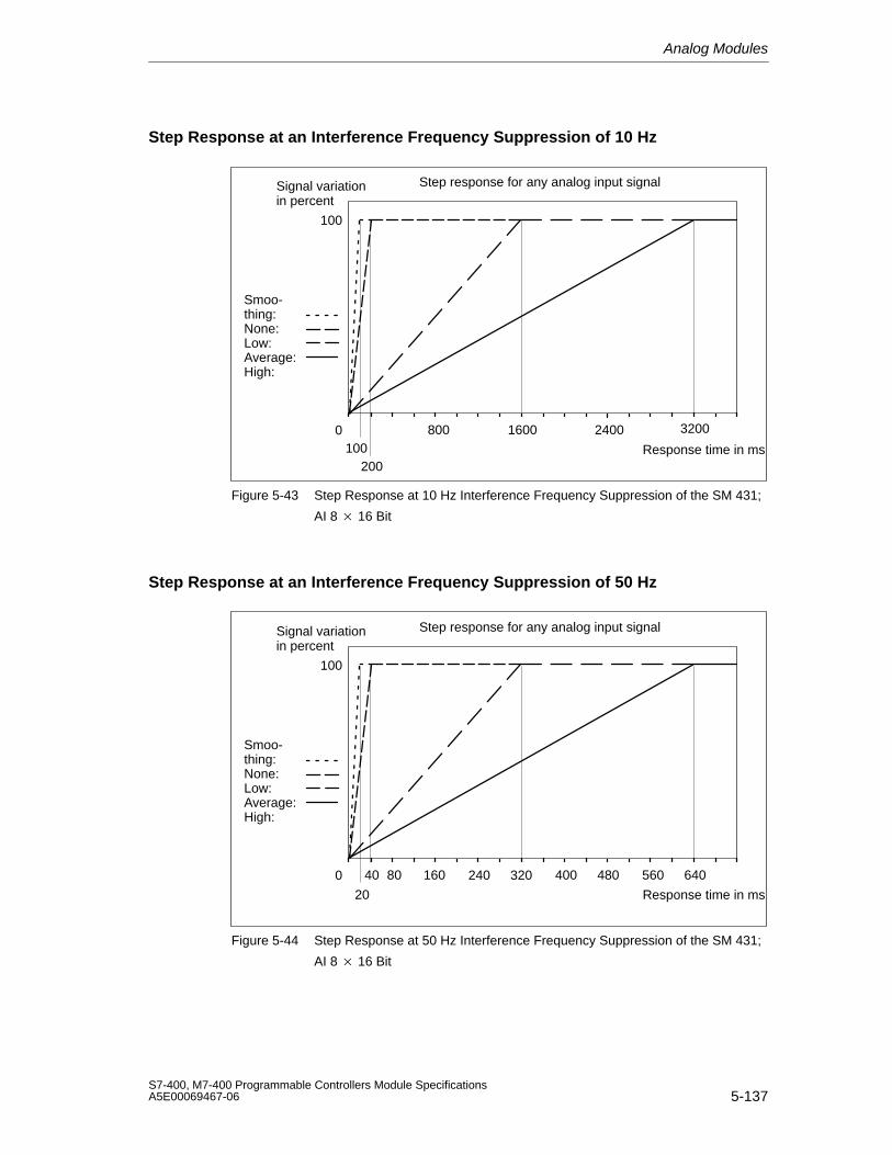
Analog Modules
5-137S7-400, M7-400 Programmable Controllers Module SpecificationsA5E00069467-06
Step Response at an Interference Frequency Suppression of 10 Hz
100
0
Smoo-thing:None:Low:Average:High:
Response time in ms
Signal variationin percent
Step response for any analog input signal
100200
1600 32002400800
Figure 5-43 Step Response at 10 Hz Interference Frequency Suppression of the SM 431;
AI 8 16 Bit
Step Response at an Interference Frequency Suppression of 50 Hz
100
0
Smoo-thing:None:Low:Average:High:
Response time in ms
Signal variationin percent
Step response for any analog input signal
16080 240 320 400 480 560 64040
20
Figure 5-44 Step Response at 50 Hz Interference Frequency Suppression of the SM 431;
AI 8 16 Bit
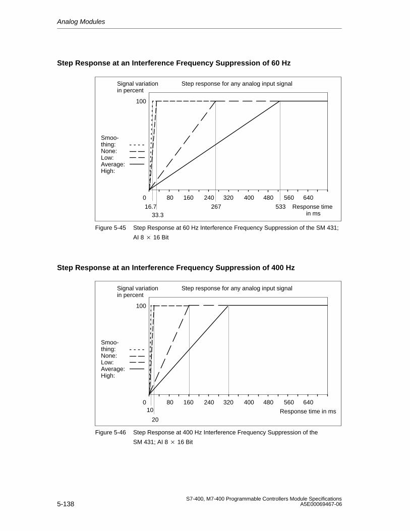
Analog Modules
5-138S7-400, M7-400 Programmable Controllers Module Specifications
A5E00069467-06
Step Response at an Interference Frequency Suppression of 60 Hz
100
0
Smoo-thing:None:Low:Average:High:
Response time in ms
Signal variationin percent
Step response for any analog input signal
16080 240 320 400 480 560 640
16.7 267 53333.3
Figure 5-45 Step Response at 60 Hz Interference Frequency Suppression of the SM 431;
AI 8 16 Bit
Step Response at an Interference Frequency Suppression of 400 Hz
100
0
Smoo-thing:None:Low:Average:High:
Response time in ms
Signal variationin percent
Step response for any analog input signal
16080 240 320 400 480 560 64010
20
Figure 5-46 Step Response at 400 Hz Interference Frequency Suppression of the
SM 431; AI 8 16 Bit
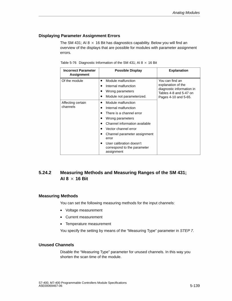
Analog Modules
5-139S7-400, M7-400 Programmable Controllers Module SpecificationsA5E00069467-06
Displaying Parameter Assignment Errors
The SM 431; AI 8 16 Bit has diagnostics capability. Below you will find anoverview of the displays that are possible for modules with parameter assignmenterrors.
Table 5-76 Diagnostic Information of the SM 431; AI 8 16 Bit
Incorrect ParameterAssignment
Possible Display Explanation
Of the module • Module malfunction
• Internal malfunction
• Wrong parameters
• Module not parameterized.
You can find anexplanation of thediagnostic information inTables 4-8 and 5-47 onPages 4-10 and 5-65.
Affecting certainchannels
• Module malfunction
• Internal malfunction
• There is a channel error
• Wrong parameters
• Channel information available
• Vector channel error
• Channel parameter assignmenterror
• User calibration doesn’tcorrespond to the parameterassignment
5.24.2 Measuring Methods and Measuring Ranges of the SM 431;AI 8 16 Bit
Measuring Methods
You can set the following measuring methods for the input channels:
• Voltage measurement
• Current measurement
• Temperature measurement
You specify the setting by means of the “Measuring Type” parameter in STEP 7.
Unused Channels
Disable the “Measuring Type” parameter for unused channels. In this way youshorten the scan time of the module.
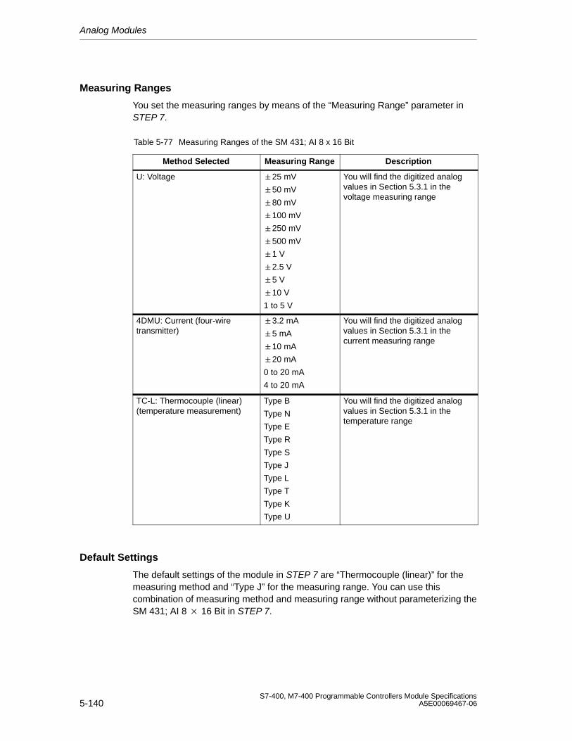
Analog Modules
5-140S7-400, M7-400 Programmable Controllers Module Specifications
A5E00069467-06
Measuring Ranges
You set the measuring ranges by means of the “Measuring Range” parameter inSTEP 7.
Table 5-77 Measuring Ranges of the SM 431; AI 8 x 16 Bit
Method Selected Measuring Range Description
U: Voltage 25 mV
50 mV
80 mV
100 mV
250 mV
500 mV
1 V
2.5 V
5 V
10 V
1 to 5 V
You will find the digitized analogvalues in Section 5.3.1 in thevoltage measuring range
4DMU: Current (four-wiretransmitter)
3.2 mA
5 mA
10 mA
20 mA
0 to 20 mA
4 to 20 mA
You will find the digitized analogvalues in Section 5.3.1 in thecurrent measuring range
TC-L: Thermocouple (linear)(temperature measurement)
Type B
Type N
Type E
Type R
Type S
Type J
Type L
Type T
Type K
Type U
You will find the digitized analogvalues in Section 5.3.1 in thetemperature range
Default Settings
The default settings of the module in STEP 7 are “Thermocouple (linear)” for themeasuring method and “Type J” for the measuring range. You can use thiscombination of measuring method and measuring range without parameterizing theSM 431; AI 8 16 Bit in STEP 7.
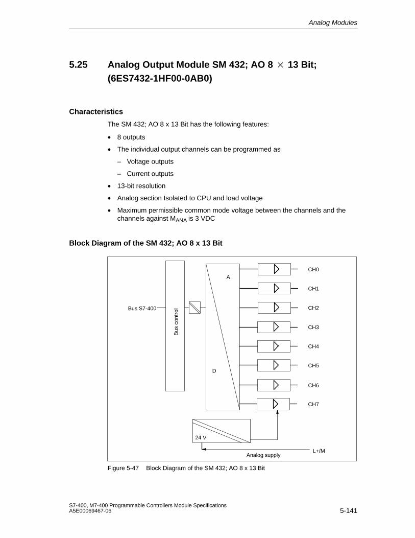
Analog Modules
5-141S7-400, M7-400 Programmable Controllers Module SpecificationsA5E00069467-06
5.25 Analog Output Module SM 432; AO 8 13 Bit;(6ES7432-1HF00-0AB0)
Characteristics
The SM 432; AO 8 x 13 Bit has the following features:
• 8 outputs
• The individual output channels can be programmed as
– Voltage outputs
– Current outputs
• 13-bit resolution
• Analog section Isolated to CPU and load voltage
• Maximum permissible common mode voltage between the channels and thechannels against MANA is 3 VDC
Block Diagram of the SM 432; AO 8 x 13 Bit
Bus S7-400
D
A
24 V
Analog supply
CH1
CH2
CH3
CH4
CH5
CH6
CH7
CH0
L+/M
Bus
con
trol
Figure 5-47 Block Diagram of the SM 432; AO 8 x 13 Bit
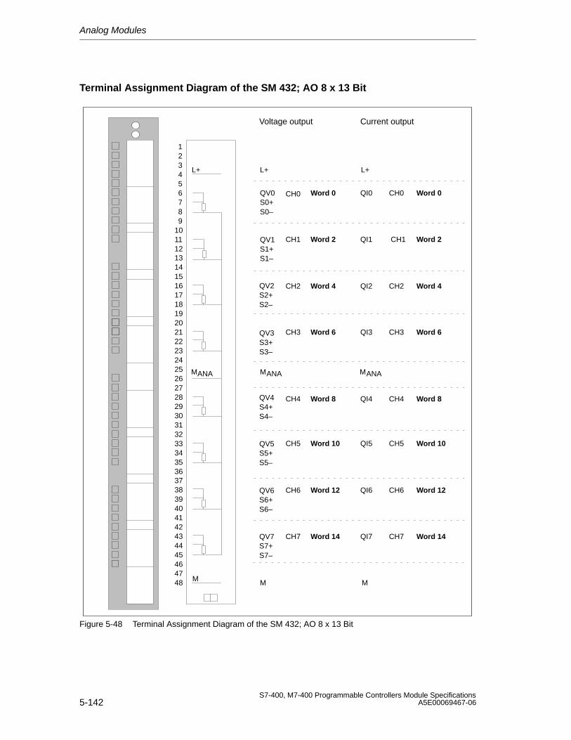
Analog Modules
5-142S7-400, M7-400 Programmable Controllers Module Specifications
A5E00069467-06
Terminal Assignment Diagram of the SM 432; AO 8 x 13 Bit
Voltage output Current output
S0–
CH0
CH1
CH2
CH3
CH4
CH5
CH6
CH7
L+
M
L+
QV0S0+
M
QI0
QI1
QI2
QI3
CH0
CH2
CH3
QI4
QI5
QI6
QI7
CH4
CH5
CH6
CH7
L+
MANA
S1–
QV1S1+
S2–
QV2S2+
S3–
QV3S3+
S4–
QV4S4+
S5–
QV5S5+
S6–
QV6S6+
S7–
QV7S7+
CH1
MANAMANA
293031323334353637
39404142434445464748
38
123456789
10111213141516171819202122232425262728
Word 0
Word 2
Word 4
Word 6
Word 8
Word 10
Word 12
Word 14
Word 0
Word 2
Word 4
Word 6
Word 8
Word 10
Word 12
Word 14
M
Figure 5-48 Terminal Assignment Diagram of the SM 432; AO 8 x 13 Bit
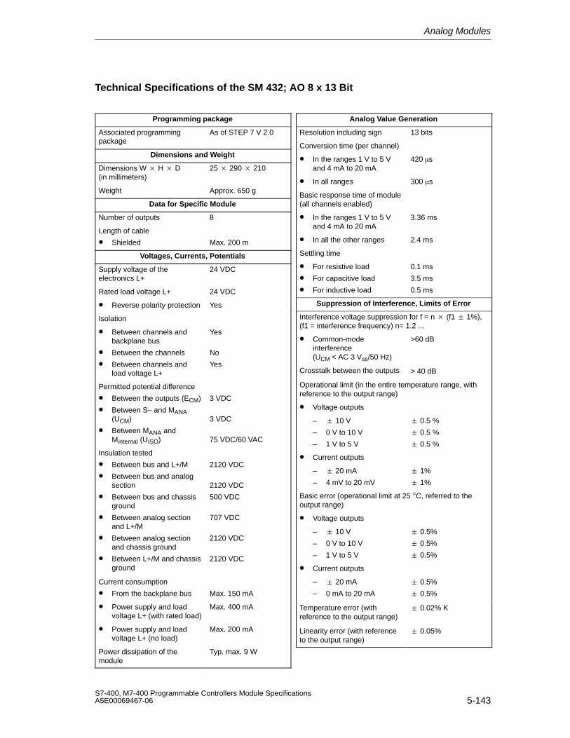
Analog Modules
5-143S7-400, M7-400 Programmable Controllers Module SpecificationsA5E00069467-06
Technical Specifications of the SM 432; AO 8 x 13 Bit
Programming package
Associated programmingpackage
As of STEP 7 V 2.0
Dimensions and Weight
Dimensions W H D(in millimeters)
25 290 210
Weight Approx. 650 g
Data for Specific Module
Number of outputs 8
Length of cable
• Shielded Max. 200 m
Voltages, Currents, Potentials
Supply voltage of theelectronics L+
24 VDC
Rated load voltage L+ 24 VDC
• Reverse polarity protection Yes
Isolation
• Between channels andbackplane bus
• Between the channels
• Between channels andload voltage L+
Yes
No
Yes
Permitted potential difference
• Between the outputs (ECM)
• Between S– and MANA(UCM)
• Between MANA andMinternal (UISO)
3 VDC
3 VDC
75 VDC/60 VAC
Insulation tested
• Between bus and L+/M
• Between bus and analogsection
• Between bus and chassisground
• Between analog sectionand L+/M
• Between analog sectionand chassis ground
• Between L+/M and chassisground
2120 VDC
2120 VDC
500 VDC
707 VDC
2120 VDC
2120 VDC
Current consumption
• From the backplane bus Max. 150 mA
• Power supply and loadvoltage L+ (with rated load)
Max. 400 mA
• Power supply and loadvoltage L+ (no load)
Max. 200 mA
Power dissipation of themodule
Typ. max. 9 W
Analog Value Generation
Resolution including sign 13 bits
Conversion time (per channel)
• In the ranges 1 V to 5 Vand 4 mA to 20 mA
420 s
• In all ranges 300 s
Basic response time of module(all channels enabled)
• In the ranges 1 V to 5 Vand 4 mA to 20 mA
3.36 ms
• In all the other ranges 2.4 ms
Settling time
• For resistive load
• For capacitive load
• For inductive load
0.1 ms
3.5 ms
0.5 ms
Suppression of Interference, Limits of Error
Interference voltage suppression for f = n (f1 1%),(f1 = interference frequency) n= 1.2 ...
• Common-modeinterference (UCM < AC 3 Vss/50 Hz)
>60 dB
Crosstalk between the outputs > 40 dB
Operational limit (in the entire temperature range, withreference to the output range)
• Voltage outputs
– 10 V
– 0 V to 10 V
– 1 V to 5 V
0.5 %
0.5 %
0.5 %
• Current outputs
– 20 mA
– 4 mV to 20 mV
1%
1%
Basic error (operational limit at 25 °C, referred to theoutput range)
• Voltage outputs
– 10 V
– 0 V to 10 V
– 1 V to 5 V
0.5%
0.5%
0.5%
• Current outputs
– 20 mA
– 0 mA to 20 mA
0.5%
0.5%
Temperature error (withreference to the output range)
0.02% K
Linearity error (with referenceto the output range)
0.05%
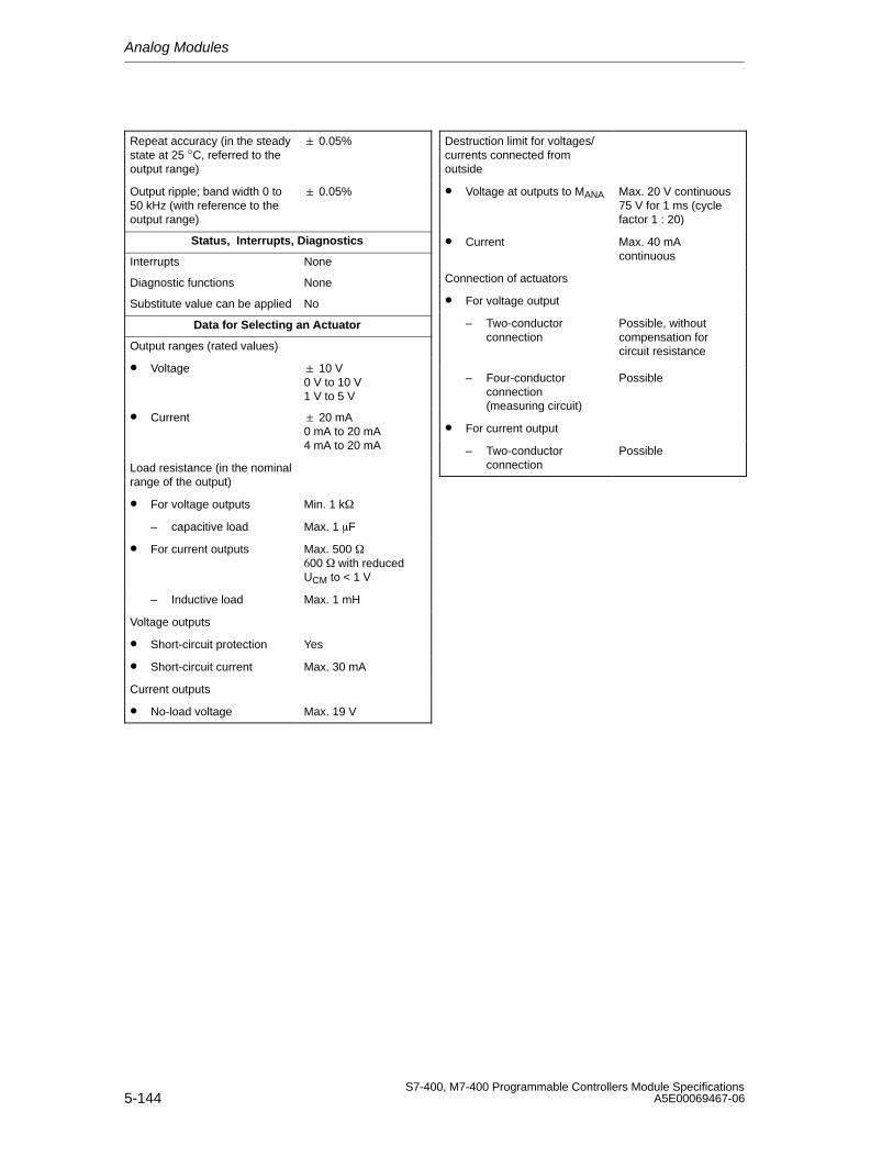
Analog Modules
5-144S7-400, M7-400 Programmable Controllers Module Specifications
A5E00069467-06
Repeat accuracy (in the steadystate at 25 °C, referred to theoutput range)
0.05%
Output ripple; band width 0 to50 kHz (with reference to theoutput range)
0.05%
Status, Interrupts, Diagnostics
Interrupts None
Diagnostic functions None
Substitute value can be applied No
Data for Selecting an Actuator
Output ranges (rated values)
• Voltage 10 V0 V to 10 V1 V to 5 V
• Current 20 mA0 mA to 20 mA4 mA to 20 mA
Load resistance (in the nominalrange of the output)
• For voltage outputs Min. 1 k
– capacitive load Max. 1 F
• For current outputs Max. 500 00 with reducedUCM to < 1 V
– Inductive load Max. 1 mH
Voltage outputs
• Short-circuit protection Yes
• Short-circuit current Max. 30 mA
Current outputs
• No-load voltage Max. 19 V
Destruction limit for voltages/currents connected fromoutside
• Voltage at outputs to MANA Max. 20 V continuous75 V for 1 ms (cyclefactor 1 : 20)
• Current Max. 40 mAcontinuous
Connection of actuators
• For voltage output
– Two-conductorconnection
Possible, withoutcompensation forcircuit resistance
– Four-conductorconnection (measuring circuit)
Possible
• For current output
– Two-conductorconnection
Possible
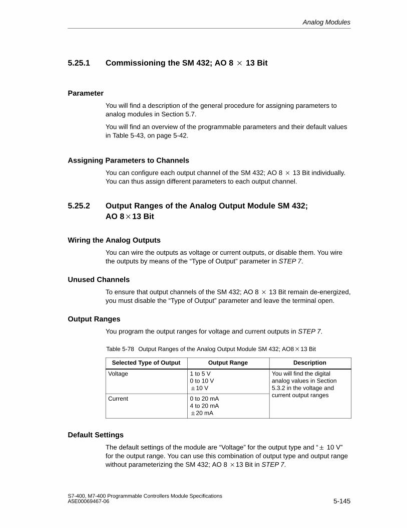
Analog Modules
5-145S7-400, M7-400 Programmable Controllers Module SpecificationsA5E00069467-06
5.25.1 Commissioning the SM 432; AO 8 13 Bit
Parameter
You will find a description of the general procedure for assigning parameters toanalog modules in Section 5.7.
You will find an overview of the programmable parameters and their default valuesin Table 5-43, on page 5-42.
Assigning Parameters to Channels
You can configure each output channel of the SM 432; AO 8 13 Bit individually.You can thus assign different parameters to each output channel.
5.25.2 Output Ranges of the Analog Output Module SM 432;AO 813 Bit
Wiring the Analog Outputs
You can wire the outputs as voltage or current outputs, or disable them. You wirethe outputs by means of the “Type of Output” parameter in STEP 7.
Unused Channels
To ensure that output channels of the SM 432; AO 8 13 Bit remain de-energized,you must disable the “Type of Output” parameter and leave the terminal open.
Output Ranges
You program the output ranges for voltage and current outputs in STEP 7.
Table 5-78 Output Ranges of the Analog Output Module SM 432; AO813 Bit
Selected Type of Output Output Range Description
Voltage 1 to 5 V0 to 10 V10 V
You will find the digitalanalog values in Section5.3.2 in the voltage and
Current 0 to 20 mA4 to 20 mA20 mA
current output ranges
Default Settings
The default settings of the module are “Voltage” for the output type and “ 10 V”for the output range. You can use this combination of output type and output rangewithout parameterizing the SM 432; AO 8 13 Bit in STEP 7.

Analog Modules
5-146S7-400, M7-400 Programmable Controllers Module Specifications
A5E00069467-06
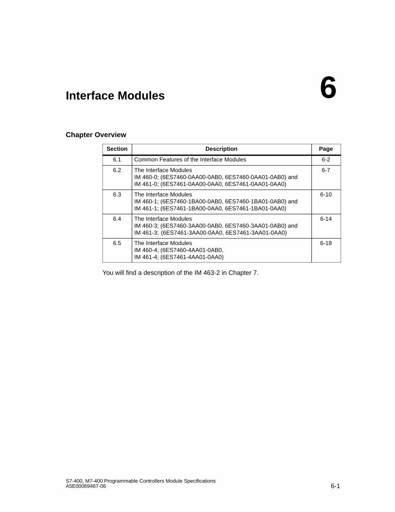
6-1S7-400, M7-400 Programmable Controllers Module SpecificationsA5E00069467-06
Interface Modules
Chapter Overview
Section Description Page
6.1 Common Features of the Interface Modules 6-2
6.2 The Interface Modules IM 460-0; (6ES7460-0AA00-0AB0, 6ES7460-0AA01-0AB0) and IM 461-0; (6ES7461-0AA00-0AA0, 6ES7461-0AA01-0AA0)
6-7
6.3 The Interface Modules IM 460-1; (6ES7460-1BA00-0AB0, 6ES7460-1BA01-0AB0) and IM 461-1; (6ES7461-1BA00-0AA0, 6ES7461-1BA01-0AA0)
6-10
6.4 The Interface Modules IM 460-3; (6ES7460-3AA00-0AB0, 6ES7460-3AA01-0AB0) and IM 461-3; (6ES7461-3AA00-0AA0, 6ES7461-3AA01-0AA0)
6-14
6.5 The Interface Modules IM 460-4; (6ES7460-4AA01-0AB0, IM 461-4; (6ES7461-4AA01-0AA0)
6-18
You will find a description of the IM 463-2 in Chapter 7.
6
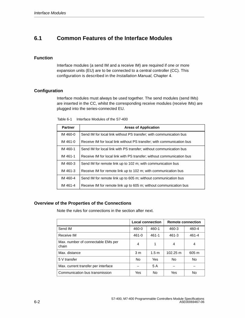
Interface Modules
6-2S7-400, M7-400 Programmable Controllers Module Specifications
A5E00069467-06
6.1 Common Features of the Interface Modules
Function
Interface modules (a send IM and a receive IM) are required if one or moreexpansion units (EU) are to be connected to a central controller (CC). Thisconfiguration is described in the Installation Manual, Chapter 4.
Configuration
Interface modules must always be used together. The send modules (send IMs)are inserted in the CC, whilst the corresponding receive modules (receive IMs) areplugged into the series-connected EU.
Table 6-1 Interface Modules of the S7-400
Partner Areas of Application
IM 460-0 Send IM for local link without PS transfer; with communication bus
IM 461-0 Receive IM for local link without PS transfer; with communication bus
IM 460-1 Send IM for local link with PS transfer; without communication bus
IM 461-1 Receive IM for local link with PS transfer; without communication bus
IM 460-3 Send IM for remote link up to 102 m; with communication bus
IM 461-3 Receive IM for remote link up to 102 m; with communication bus
IM 460-4 Send IM for remote link up to 605 m; without communication bus
IM 461-4 Receive IM for remote link up to 605 m; without communication bus
Overview of the Properties of the Connections
Note the rules for connections in the section after next.
Local connection Remote connection
Send IM 460-0 460-1 460-3 460-4
Receive IM 461-0 461-1 461-3 461-4
Max. number of connectable EMs perchain
4 1 4 4
Max. distance 3 m 1.5 m 102.25 m 605 m
5 V transfer No Yes No No
Max. current transfer per interface – 5 A – –
Communication bus transmission Yes No Yes No
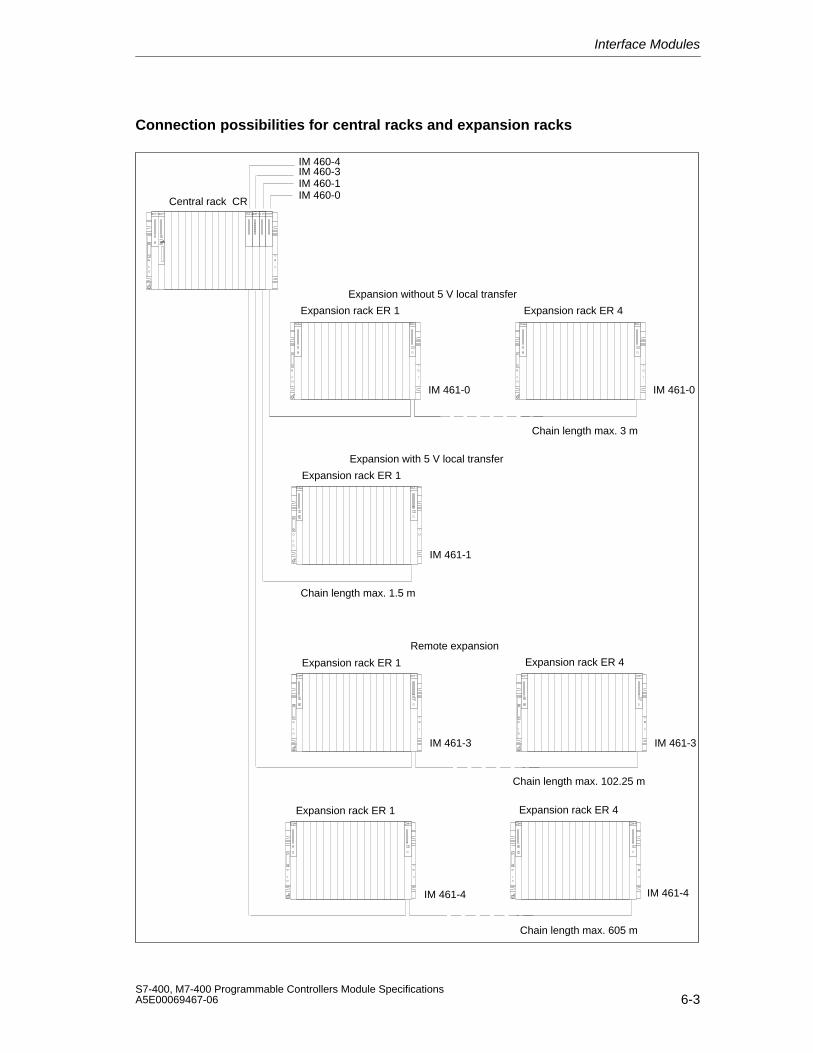
Interface Modules
6-3S7-400, M7-400 Programmable Controllers Module SpecificationsA5E00069467-06
Connection possibilities for central racks and expansion racks
Central rack CR
Expansion rack ER 1 Expansion rack ER 4
Expansion rack ER 1
Expansion rack ER 1 Expansion rack ER 4
Expansion without 5 V local transfer
Expansion with 5 V local transfer
Remote expansion
IM 460-0IM 460-1IM 460-3
Chain length max. 3 m
Chain length max. 102.25 m
Chain length max. 1.5 m
IM 461-0 IM 461-0
IM 461-1
IM 461-3 IM 461-3
IM 460-4
Expansion rack ER 1 Expansion rack ER 4
Chain length max. 605 m
IM 461-4 IM 461-4
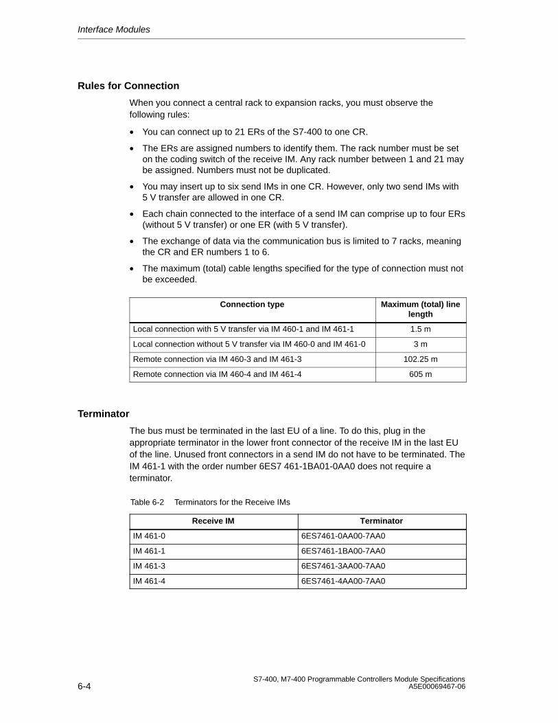
Interface Modules
6-4S7-400, M7-400 Programmable Controllers Module Specifications
A5E00069467-06
Rules for Connection
When you connect a central rack to expansion racks, you must observe thefollowing rules:
• You can connect up to 21 ERs of the S7-400 to one CR.
• The ERs are assigned numbers to identify them. The rack number must be seton the coding switch of the receive IM. Any rack number between 1 and 21 maybe assigned. Numbers must not be duplicated.
• You may insert up to six send IMs in one CR. However, only two send IMs with5 V transfer are allowed in one CR.
• Each chain connected to the interface of a send IM can comprise up to four ERs(without 5 V transfer) or one ER (with 5 V transfer).
• The exchange of data via the communication bus is limited to 7 racks, meaningthe CR and ER numbers 1 to 6.
• The maximum (total) cable lengths specified for the type of connection must notbe exceeded.
Connection type Maximum (total) linelength
Local connection with 5 V transfer via IM 460-1 and IM 461-1 1.5 m
Local connection without 5 V transfer via IM 460-0 and IM 461-0 3 m
Remote connection via IM 460-3 and IM 461-3 102.25 m
Remote connection via IM 460-4 and IM 461-4 605 m
Terminator
The bus must be terminated in the last EU of a line. To do this, plug in theappropriate terminator in the lower front connector of the receive IM in the last EUof the line. Unused front connectors in a send IM do not have to be terminated. TheIM 461-1 with the order number 6ES7 461-1BA01-0AA0 does not require aterminator.
Table 6-2 Terminators for the Receive IMs
Receive IM Terminator
IM 461-0 6ES7461-0AA00-7AA0
IM 461-1 6ES7461-1BA00-7AA0
IM 461-3 6ES7461-3AA00-7AA0
IM 461-4 6ES7461-4AA00-7AA0
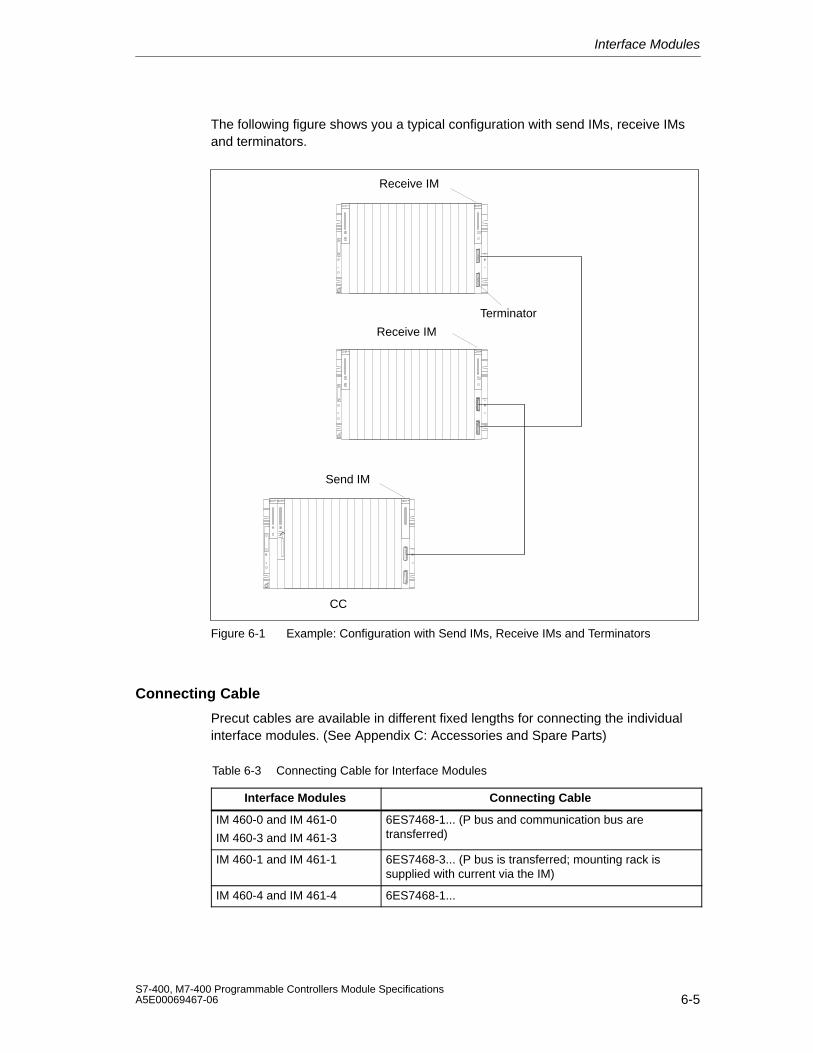
Interface Modules
6-5S7-400, M7-400 Programmable Controllers Module SpecificationsA5E00069467-06
The following figure shows you a typical configuration with send IMs, receive IMsand terminators.
CC
Send IM
Receive IM
Receive IM
Terminator
Figure 6-1 Example: Configuration with Send IMs, Receive IMs and Terminators
Connecting Cable
Precut cables are available in different fixed lengths for connecting the individualinterface modules. (See Appendix C: Accessories and Spare Parts)
Table 6-3 Connecting Cable for Interface Modules
Interface Modules Connecting Cable
IM 460-0 and IM 461-0
IM 460-3 and IM 461-3
6ES7468-1... (P bus and communication bus aretransferred)
IM 460-1 and IM 461-1 6ES7468-3... (P bus is transferred; mounting rack issupplied with current via the IM)
IM 460-4 and IM 461-4 6ES7468-1...
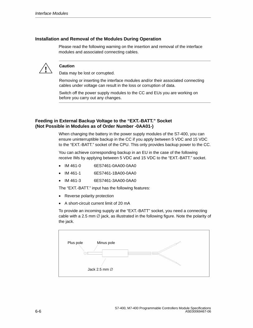
Interface Modules
6-6S7-400, M7-400 Programmable Controllers Module Specifications
A5E00069467-06
Installation and Removal of the Modules During Operation
Please read the following warning on the insertion and removal of the interfacemodules and associated connecting cables.
!Caution
Data may be lost or corrupted.
Removing or inserting the interface modules and/or their associated connectingcables under voltage can result in the loss or corruption of data.
Switch off the power supply modules to the CC and EUs you are working onbefore you carry out any changes.
Feeding in External Backup Voltage to the “EXT.-BATT.” Socket(Not Possible in Modules as of Order Number -0AA01-)
When changing the battery in the power supply modules of the S7-400, you canensure uninterruptible backup in the CC if you apply between 5 VDC and 15 VDCto the “EXT.-BATT.” socket of the CPU. This only provides backup power to the CC.
You can achieve corresponding backup in an EU in the case of the followingreceive IMs by applying between 5 VDC and 15 VDC to the “EXT.-BATT.” socket.
• IM 461-0 6ES7461-0AA00-0AA0
• IM 461-1 6ES7461-1BA00-0AA0
• IM 461-3 6ES7461-3AA00-0AA0
The “EXT.-BATT.” input has the following features:
• Reverse polarity protection
• A short-circuit current limit of 20 mA
To provide an incoming supply at the “EXT.-BATT” socket, you need a connectingcable with a 2.5 mm ∅ jack, as illustrated in the following figure. Note the polarity ofthe jack.
Plus pole Minus pole
Jack 2.5 mm ∅
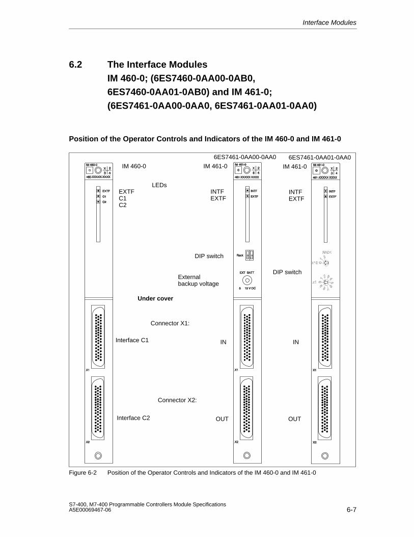
Interface Modules
6-7S7-400, M7-400 Programmable Controllers Module SpecificationsA5E00069467-06
6.2 The Interface Modules IM 460-0; (6ES7460-0AA00-0AB0,6ES7460-0AA01-0AB0) and IM 461-0;(6ES7461-0AA00-0AA0, 6ES7461-0AA01-0AA0)
Position of the Operator Controls and Indicators of the IM 460-0 and IM 461-0
LEDsEXTFC1C2
INTFEXTF
DIP switch
External backup voltage
Connector X1:
Interface C2
IM 460-0 IM 461-0
Interface C1
Connector X2:
IN
OUT
Under cover
INTFEXTF
DIP switch
IM 461-0
6ES7461-0AA00-0AA0 6ES7461-0AA01-0AA0
IN
OUT
Figure 6-2 Position of the Operator Controls and Indicators of the IM 460-0 and IM 461-0
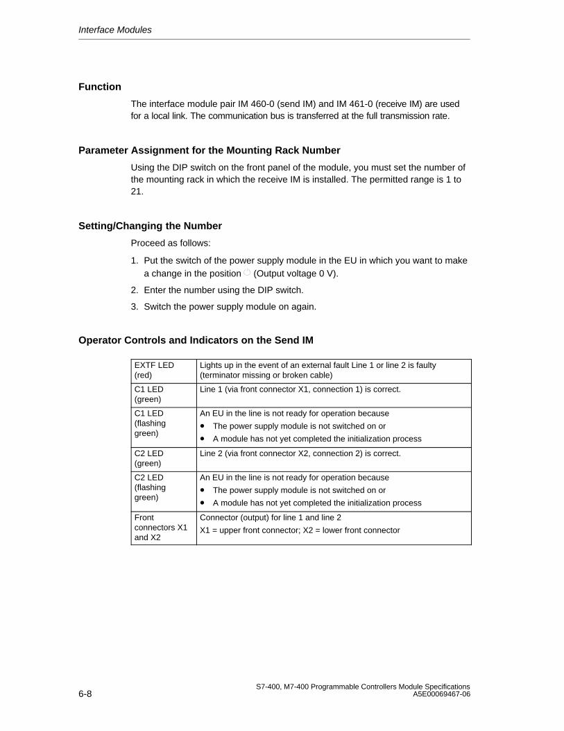
Interface Modules
6-8S7-400, M7-400 Programmable Controllers Module Specifications
A5E00069467-06
Function
The interface module pair IM 460-0 (send IM) and IM 461-0 (receive IM) are usedfor a local link. The communication bus is transferred at the full transmission rate.
Parameter Assignment for the Mounting Rack Number
Using the DIP switch on the front panel of the module, you must set the number ofthe mounting rack in which the receive IM is installed. The permitted range is 1 to21.
Setting/Changing the Number
Proceed as follows:
1. Put the switch of the power supply module in the EU in which you want to makea change in the position (Output voltage 0 V).
2. Enter the number using the DIP switch.
3. Switch the power supply module on again.
Operator Controls and Indicators on the Send IM
EXTF LED(red)
Lights up in the event of an external fault Line 1 or line 2 is faulty(terminator missing or broken cable)
C1 LED(green)
Line 1 (via front connector X1, connection 1) is correct.
C1 LED(flashinggreen)
An EU in the line is not ready for operation because
• The power supply module is not switched on or
• A module has not yet completed the initialization process
C2 LED(green)
Line 2 (via front connector X2, connection 2) is correct.
C2 LED(flashinggreen)
An EU in the line is not ready for operation because
• The power supply module is not switched on or
• A module has not yet completed the initialization process
Frontconnectors X1and X2
Connector (output) for line 1 and line 2
X1 = upper front connector; X2 = lower front connector
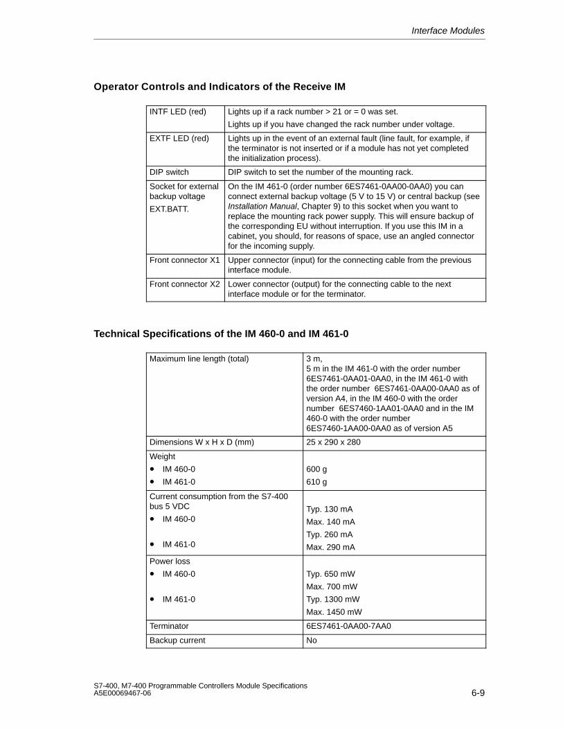
Interface Modules
6-9S7-400, M7-400 Programmable Controllers Module SpecificationsA5E00069467-06
Operator Controls and Indicators of the Receive IM
INTF LED (red) Lights up if a rack number > 21 or = 0 was set.
Lights up if you have changed the rack number under voltage.
EXTF LED (red) Lights up in the event of an external fault (line fault, for example, ifthe terminator is not inserted or if a module has not yet completedthe initialization process).
DIP switch DIP switch to set the number of the mounting rack.
Socket for externalbackup voltage
EXT.BATT.
On the IM 461-0 (order number 6ES7461-0AA00-0AA0) you canconnect external backup voltage (5 V to 15 V) or central backup (seeInstallation Manual, Chapter 9) to this socket when you want toreplace the mounting rack power supply. This will ensure backup ofthe corresponding EU without interruption. If you use this IM in acabinet, you should, for reasons of space, use an angled connectorfor the incoming supply.
Front connector X1 Upper connector (input) for the connecting cable from the previousinterface module.
Front connector X2 Lower connector (output) for the connecting cable to the nextinterface module or for the terminator.
Technical Specifications of the IM 460-0 and IM 461-0
Maximum line length (total) 3 m, 5 m in the IM 461-0 with the order number6ES7461-0AA01-0AA0, in the IM 461-0 withthe order number 6ES7461-0AA00-0AA0 as ofversion A4, in the IM 460-0 with the ordernumber 6ES7460-1AA01-0AA0 and in the IM460-0 with the order number6ES7460-1AA00-0AA0 as of version A5
Dimensions W x H x D (mm) 25 x 290 x 280
Weight
• IM 460-0
• IM 461-0
600 g
610 g
Current consumption from the S7-400bus 5 VDC
• IM 460-0
• IM 461-0
Typ. 130 mA
Max. 140 mA
Typ. 260 mA
Max. 290 mA
Power loss
• IM 460-0
• IM 461-0
Typ. 650 mW
Max. 700 mW
Typ. 1300 mW
Max. 1450 mW
Terminator 6ES7461-0AA00-7AA0
Backup current No
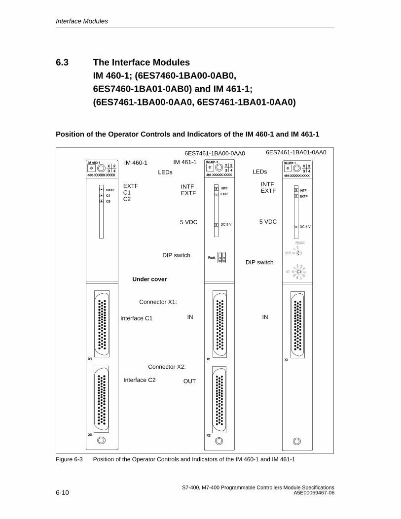
Interface Modules
6-10S7-400, M7-400 Programmable Controllers Module Specifications
A5E00069467-06
6.3 The Interface Modules IM 460-1; (6ES7460-1BA00-0AB0,6ES7460-1BA01-0AB0) and IM 461-1;(6ES7461-1BA00-0AA0, 6ES7461-1BA01-0AA0)
Position of the Operator Controls and Indicators of the IM 460-1 and IM 461-1
5 VDC
LEDs
EXTFC1C2
INTFEXTF
DIP switch
IM 460-1 IM 461-1
Connector X1:
Interface C2
Interface C1
Connector X2:
IN
OUT
Under cover
5 VDC
LEDs
INTFEXTF
DIP switch
6ES7461-1BA00-0AA0 6ES7461-1BA01-0AA0
IN
Figure 6-3 Position of the Operator Controls and Indicators of the IM 460-1 and IM 461-1
Interface Modules
6-11S7-400, M7-400 Programmable Controllers Module SpecificationsA5E00069467-06
FunctionThe interface module pair IM 460-1 (send IM) and IM 461-1 (receive IM) are usedfor a local link (up to a maximum 1.5 m in total). A 5 V supply voltage is alsotransferred with these interface modules. Please particularly remember thefollowing points:
• The current requirements of the module plugged into the EU must not exceed 5 V/5 A.
• You can only connect one EU per line.
• The modules in this mounting rack are not supplied with 24 V and are notbacked up.
• The communication bus is not transferred with the interface module pairIM 460-1 and IM 461-1.
• You must not use a power supply module in the EU.
Note
If you connect an EU via a local link with 5 V transmission, ungrounded operationis prescribed for the EU (see Installation Manual, Chapter 4)
Parameter Assignment for the Mounting Rack Number
Using the DIP switch on the front panel of the module, you must set the number ofthe mounting rack in which the receive IM is installed. The permitted range is 1 to 21.
Setting/Changing the Number
Proceed as follows:
1. Put the power supply module in the CC into the position (Output voltage 0 V).
2. Enter the number using the DIP switch.
3. Switch the power supply module on again.
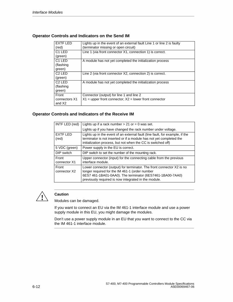
Interface Modules
6-12S7-400, M7-400 Programmable Controllers Module Specifications
A5E00069467-06
Operator Controls and Indicators on the Send IM
EXTF LED(red)
Lights up in the event of an external fault Line 1 or line 2 is faulty(terminator missing or open circuit)
C1 LED(green)
Line 1 (via front connector X1, connection 1) is correct.
C1 LED(flashinggreen)
A module has not yet completed the initialization process
C2 LED(green)
Line 2 (via front connector X2, connection 2) is correct.
C2 LED(flashinggreen)
A module has not yet completed the initialization process
Frontconnectors X1and X2
Connector (output) for line 1 and line 2X1 = upper front connector; X2 = lower front connector
Operator Controls and Indicators of the Receive IM
INTF LED (red) Lights up if a rack number > 21 or = 0 was set.
Lights up if you have changed the rack number under voltage.
EXTF LED(red)
Lights up in the event of an external fault (line fault, for example, if theterminator is not inserted or if a module has not yet completed theinitialization process, but not when the CC is switched off)
5 VDC (green) Power supply in the EU is correct.
DIP switch DIP switch to set the number of the mounting rack.
Frontconnector X1
Upper connector (input) for the connecting cable from the previousinterface module.
Frontconnector X2
Lower connector (output) for terminator. The front connector X2 is nolonger required for the IM 461-1 (order number6ES7 461-1BA01-0AA0). The terminator (6ES7461-1BA00-7AA0)previously required is now integrated in the module.
!Caution
Modules can be damaged.
If you want to connect an EU via the IM 461-1 interface module and use a powersupply module in this EU, you might damage the modules.
Don’t use a power supply module in an EU that you want to connect to the CC viathe IM 461-1 interface module.
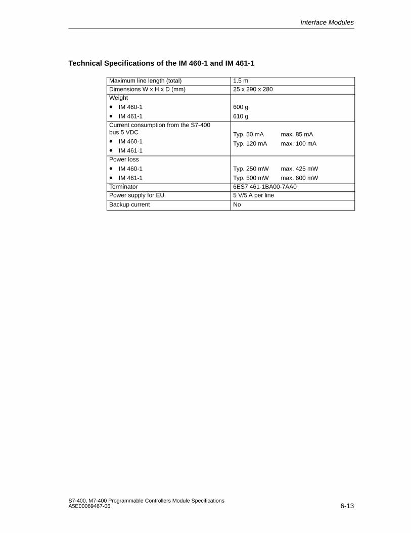
Interface Modules
6-13S7-400, M7-400 Programmable Controllers Module SpecificationsA5E00069467-06
Technical Specifications of the IM 460-1 and IM 461-1
Maximum line length (total) 1.5 mDimensions W x H x D (mm) 25 x 290 x 280Weight
• IM 460-1
• IM 461-1
600 g
610 gCurrent consumption from the S7-400bus 5 VDC
• IM 460-1
• IM 461-1
Typ. 50 mA max. 85 mA
Typ. 120 mA max. 100 mA
Power loss
• IM 460-1
• IM 461-1
Typ. 250 mW max. 425 mW
Typ. 500 mW max. 600 mWTerminator 6ES7 461-1BA00-7AA0Power supply for EU 5 V/5 A per line
Backup current No
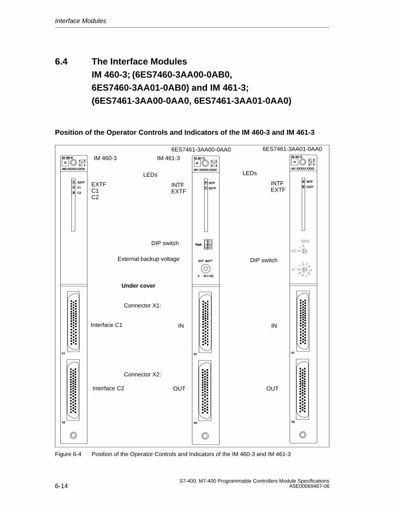
Interface Modules
6-14S7-400, M7-400 Programmable Controllers Module Specifications
A5E00069467-06
6.4 The Interface Modules IM 460-3; (6ES7460-3AA00-0AB0,6ES7460-3AA01-0AB0) and IM 461-3;(6ES7461-3AA00-0AA0, 6ES7461-3AA01-0AA0)
Position of the Operator Controls and Indicators of the IM 460-3 and IM 461-3
LEDs
EXTFC1C2
INTFEXTF
DIP switch
External backup voltage
Connector X1:
Interface C2
Interface C1
Connector X2:
IN
OUT
IM 460-3 IM 461-3
Under cover
LEDs
INTFEXTF
DIP switch
6ES7461-3AA00-0AA0 6ES7461-3AA01-0AA0
IN
OUT
Figure 6-4 Position of the Operator Controls and Indicators of the IM 460-3 and IM 461-3
Interface Modules
6-15S7-400, M7-400 Programmable Controllers Module SpecificationsA5E00069467-06
Function
The interface module pair IM 460-3 (send IM) and IM 461-3 (receive IM) are usedfor a remote link of up to a maximum 102 m (exactly: 100 m plus inputs/outputs of0.75 m in the line). The communication bus is transferred at the full transmissionrate.
Parameterization
Using the DIP switch on the front panel of the module, you must set the number ofthe mounting rack that the receive IM is installed on. The permitted range is 1 to 21.
If required, you can change the distance setting for the line on the programmingdevice using STEP 7.
The default setting for the distance is 100 m.
Ensure that the distance corresponds as closely as possible to the current length(the sum of all the connecting cables per line) as this will accelerate datatransmission.
Note
The distance set must always be longer than the actual length of cable per line.
Setting/Changing the Number
Proceed as follows:
1. Put the switch of the power supply module in the EU in which you want to makea change in the position (Output voltage 0 V).
2. Enter the number using the DIP switch.
3. Switch the power supply module on again.
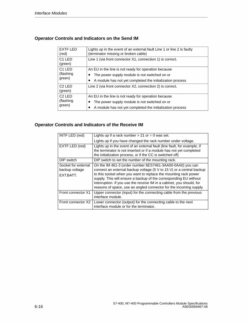
Interface Modules
6-16S7-400, M7-400 Programmable Controllers Module Specifications
A5E00069467-06
Operator Controls and Indicators on the Send IM
EXTF LED(red)
Lights up in the event of an external fault Line 1 or line 2 is faulty(terminator missing or broken cable)
C1 LED(green)
Line 1 (via front connector X1, connection 1) is correct.
C1 LED(flashinggreen)
An EU in the line is not ready for operation because
• The power supply module is not switched on or
• A module has not yet completed the initialization process
C2 LED(green)
Line 2 (via front connector X2, connection 2) is correct.
C2 LED(flashinggreen)
An EU in the line is not ready for operation because
• The power supply module is not switched on or
• A module has not yet completed the initialization process
Operator Controls and Indicators of the Receive IM
INTF LED (red) Lights up if a rack number > 21 or = 0 was set.
Lights up if you have changed the rack number under voltage.EXTF LED (red) Lights up in the event of an external fault (line fault, for example, if
the terminator is not inserted or if a module has not yet completedthe initialization process, or if the CC is switched off)
DIP switch DIP switch to set the number of the mounting rack.Socket for externalbackup voltage
EXT.BATT.
On the IM 461-3 (order number 6ES7461-3AA00-0AA0) you canconnect an external backup voltage (5 V to 15 V) or a central backupto this socket when you want to replace the mounting rack powersupply. This will ensure a backup of the corresponding EU withoutinterruption. If you use the receive IM in a cabinet, you should, forreasons of space, use an angled connector for the incoming supply.
Front connector X1 Upper connector (input) for the connecting cable from the previousinterface module.
Front connector X2 Lower connector (output) for the connecting cable to the nextinterface module or for the terminator.
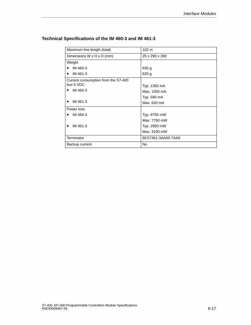
Interface Modules
6-17S7-400, M7-400 Programmable Controllers Module SpecificationsA5E00069467-06
Technical Specifications of the IM 460-3 and IM 461-3
Maximum line length (total) 102 m
Dimensions W x H x D (mm) 25 x 290 x 280
Weight
• IM 460-3
• IM 461-3
630 g
620 g
Current consumption from the S7-400bus 5 VDC
• IM 460-3
• IM 461-3
Typ. 1350 mA
Max. 1550 mA
Typ. 590 mA
Max. 620 mA
Power loss
• IM 460-3
• IM 461-3
Typ. 6750 mW
Max. 7750 mW
Typ. 2950 mW
Max. 3100 mW
Terminator 6ES7461-3AA00-7AA0
Backup current No
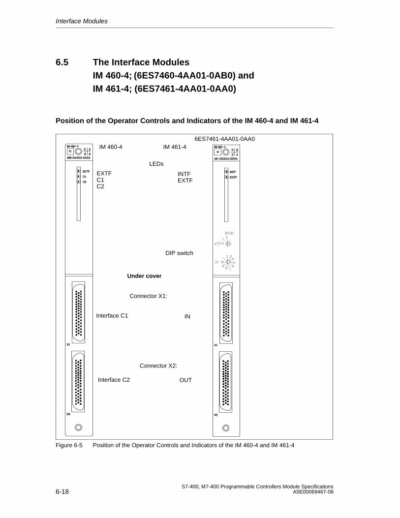
Interface Modules
6-18S7-400, M7-400 Programmable Controllers Module Specifications
A5E00069467-06
6.5 The Interface Modules IM 460-4; (6ES7460-4AA01-0AB0) and IM 461-4; (6ES7461-4AA01-0AA0)
Position of the Operator Controls and Indicators of the IM 460-4 and IM 461-4
LEDs
EXTFC1C2
INTFEXTF
DIP switch
Connector X1:
Interface C2
Interface C1
Connector X2:
IN
OUT
IM 460-4 IM 461-4
Under cover
6ES7461-4AA01-0AA0
Figure 6-5 Position of the Operator Controls and Indicators of the IM 460-4 and IM 461-4
Interface Modules
6-19S7-400, M7-400 Programmable Controllers Module SpecificationsA5E00069467-06
Function
The interface module pair IM 460-4 (send IM) and IM 461-4 (receive IM) are usedfor a remote link of up to a maximum 605 m (exactly: 600 m plus inputs/outputs of1.5 m in the line).
Parameterization
Using the DIP switch on the front panel of the module, you must set the number ofthe mounting rack in which the receive IM is installed. The permitted range is 1 to 21.
If required, you can change the distance setting for the line on the programmingdevice using STEP 7.
The default setting for the distance is 600 m.
Ensure that the distance corresponds as closely as possible to the current length(the sum of all the connecting cables per line) as this will accelerate datatransmission.
Note
The distance set must always be longer than the actual length of cable per line.
Setting/Changing the Number
Proceed as follows:
1. Put the switch of the power supply module in the EU in which you want to makethe change in the position (Output voltage 0 V).
2. Enter the number using the DIP switch.
3. Switch the power supply module on again.
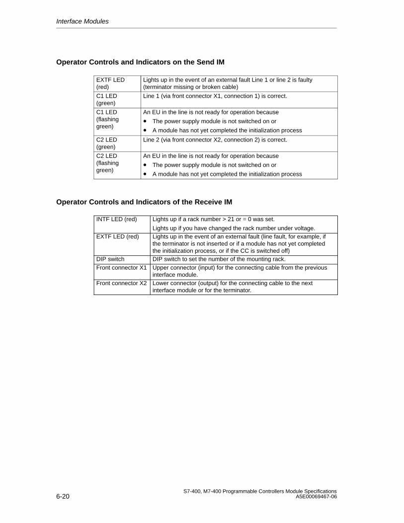
Interface Modules
6-20S7-400, M7-400 Programmable Controllers Module Specifications
A5E00069467-06
Operator Controls and Indicators on the Send IM
EXTF LED(red)
Lights up in the event of an external fault Line 1 or line 2 is faulty(terminator missing or broken cable)
C1 LED(green)
Line 1 (via front connector X1, connection 1) is correct.
C1 LED(flashinggreen)
An EU in the line is not ready for operation because
• The power supply module is not switched on or
• A module has not yet completed the initialization process
C2 LED(green)
Line 2 (via front connector X2, connection 2) is correct.
C2 LED(flashinggreen)
An EU in the line is not ready for operation because
• The power supply module is not switched on or
• A module has not yet completed the initialization process
Operator Controls and Indicators of the Receive IM
INTF LED (red) Lights up if a rack number > 21 or = 0 was set.
Lights up if you have changed the rack number under voltage.EXTF LED (red) Lights up in the event of an external fault (line fault, for example, if
the terminator is not inserted or if a module has not yet completedthe initialization process, or if the CC is switched off)
DIP switch DIP switch to set the number of the mounting rack.Front connector X1 Upper connector (input) for the connecting cable from the previous
interface module.Front connector X2 Lower connector (output) for the connecting cable to the next
interface module or for the terminator.
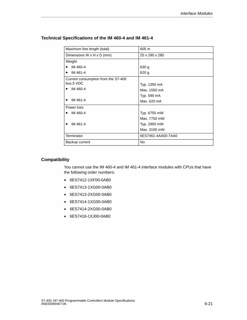
Interface Modules
6-21S7-400, M7-400 Programmable Controllers Module SpecificationsA5E00069467-06
Technical Specifications of the IM 460-4 and IM 461-4
Maximum line length (total) 605 m
Dimensions W x H x D (mm) 25 x 290 x 280
Weight
• IM 460-4
• IM 461-4
630 g
620 g
Current consumption from the S7-400bus 5 VDC
• IM 460-4
• IM 461-4
Typ. 1350 mA
Max. 1550 mA
Typ. 590 mA
Max. 620 mA
Power loss
• IM 460-4
• IM 461-4
Typ. 6750 mW
Max. 7750 mW
Typ. 2950 mW
Max. 3100 mW
Terminator 6ES7461-4AA00-7AA0
Backup current No
Compatibility
You cannot use the IM 460-4 and IM 461-4 interface modules with CPUs that havethe following order numbers:
• 6ES7412-1XF00-0AB0
• 6ES7413-1XG00-0AB0
• 6ES7413-2XG00-0AB0
• 6ES7414-1XG00-0AB0
• 6ES7414-2XG00-0AB0
• 6ES7416-1XJ00-0AB0

Interface Modules
6-22S7-400, M7-400 Programmable Controllers Module Specifications
A5E00069467-06
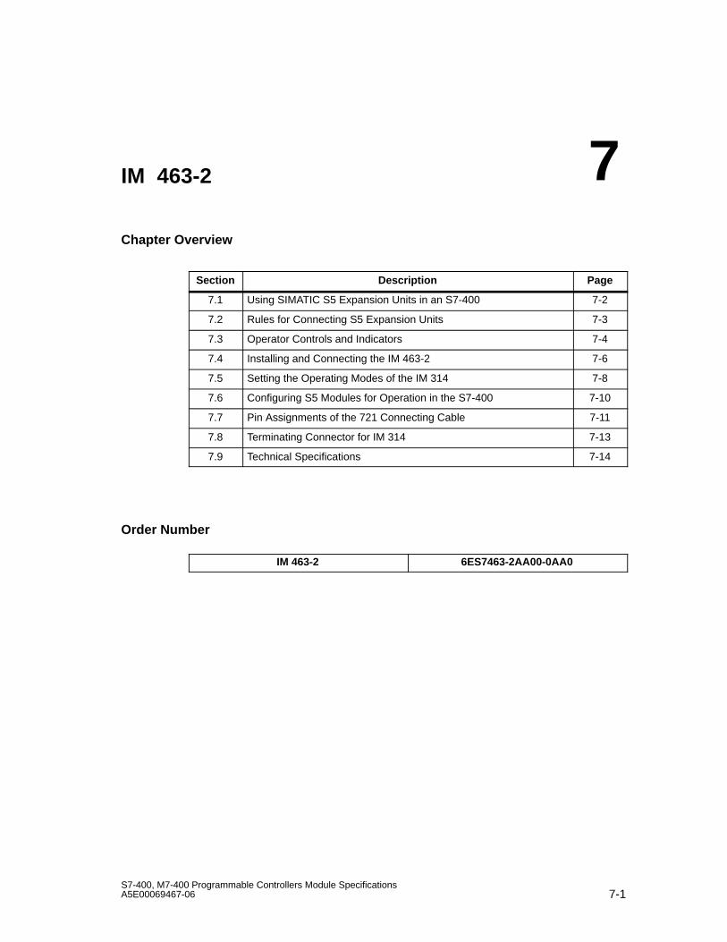
7-1S7-400, M7-400 Programmable Controllers Module SpecificationsA5E00069467-06
IM 463-2
Chapter Overview
Section Description Page
7.1 Using SIMATIC S5 Expansion Units in an S7-400 7-2
7.2 Rules for Connecting S5 Expansion Units 7-3
7.3 Operator Controls and Indicators 7-4
7.4 Installing and Connecting the IM 463-2 7-6
7.5 Setting the Operating Modes of the IM 314 7-8
7.6 Configuring S5 Modules for Operation in the S7-400 7-10
7.7 Pin Assignments of the 721 Connecting Cable 7-11
7.8 Terminating Connector for IM 314 7-13
7.9 Technical Specifications 7-14
Order Number
IM 463-2 6ES7463-2AA00-0AA0
7
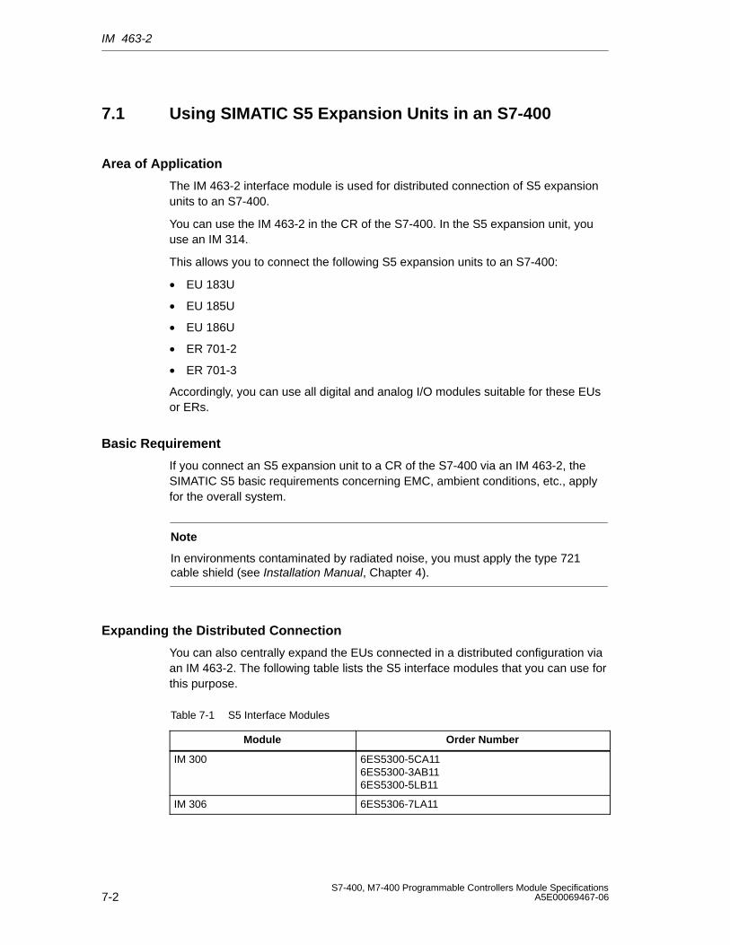
IM 463-2
7-2S7-400, M7-400 Programmable Controllers Module Specifications
A5E00069467-06
7.1 Using SIMATIC S5 Expansion Units in an S7-400
Area of Application
The IM 463-2 interface module is used for distributed connection of S5 expansionunits to an S7-400.
You can use the IM 463-2 in the CR of the S7-400. In the S5 expansion unit, youuse an IM 314.
This allows you to connect the following S5 expansion units to an S7-400:
• EU 183U
• EU 185U
• EU 186U
• ER 701-2
• ER 701-3
Accordingly, you can use all digital and analog I/O modules suitable for these EUsor ERs.
Basic Requirement
If you connect an S5 expansion unit to a CR of the S7-400 via an IM 463-2, theSIMATIC S5 basic requirements concerning EMC, ambient conditions, etc., applyfor the overall system.
Note
In environments contaminated by radiated noise, you must apply the type 721cable shield (see Installation Manual, Chapter 4).
Expanding the Distributed Connection
You can also centrally expand the EUs connected in a distributed configuration viaan IM 463-2. The following table lists the S5 interface modules that you can use forthis purpose.
Table 7-1 S5 Interface Modules
Module Order Number
IM 300 6ES5300-5CA116ES5300-3AB116ES5300-5LB11
IM 306 6ES5306-7LA11
IM 463-2
7-3S7-400, M7-400 Programmable Controllers Module SpecificationsA5E00069467-06
7.2 Rules for Connecting S5 Expansion Units
Introduction
When you connect S5 expansion units to an S7-400 via the IM 463-2, there arerules to observe with regard to cable length, maximum expansion, use of aterminating connector and permissible potential differences.
Cable Length
The maximum cable length per IM 463-2 from the CR of the S7-400 to the lastS5 expansion unit is 600 m. You set the actual cable length at the IM 463-2(see Section 7.3).
Maximum Expansion
You can use up to four IM 463-2s in one S7-400 CR.
At each IM 463-2 interface (C1 and C2), you can connect up to four S5 expansionunits in a distributed configuration.
You can connect further EUs centrally to the EUs connected in the distributedconfiguration.
Addressing of the S5 modules
All S5 address areas are available (P, Q, IM3, IM4)
Note
Note that every S5 address can only be used once, even across different chains.
Terminating Connector
You must terminate the IM 314 of the last EU in each chain with the6ES5760-1AA11 terminating connector.
Permissible Potential Differences
For the safe functioning of the distributed configuration, you must ensure that thepotential difference between two devices is not more than 7 V. Use an equipotentialbonding conductor.
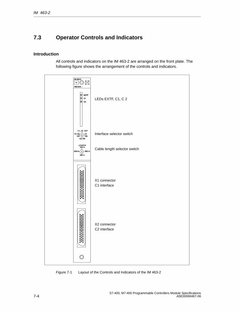
IM 463-2
7-4S7-400, M7-400 Programmable Controllers Module Specifications
A5E00069467-06
7.3 Operator Controls and Indicators
Introduction
All controls and indicators on the IM 463-2 are arranged on the front plate. Thefollowing figure shows the arrangement of the controls and indicators.
LEDs EXTF, C1, C 2
Interface selector switch
Cable length selector switch
C1 interface
C2 interface
X1 connector
X2 connector
Figure 7-1 Layout of the Controls and Indicators of the IM 463-2
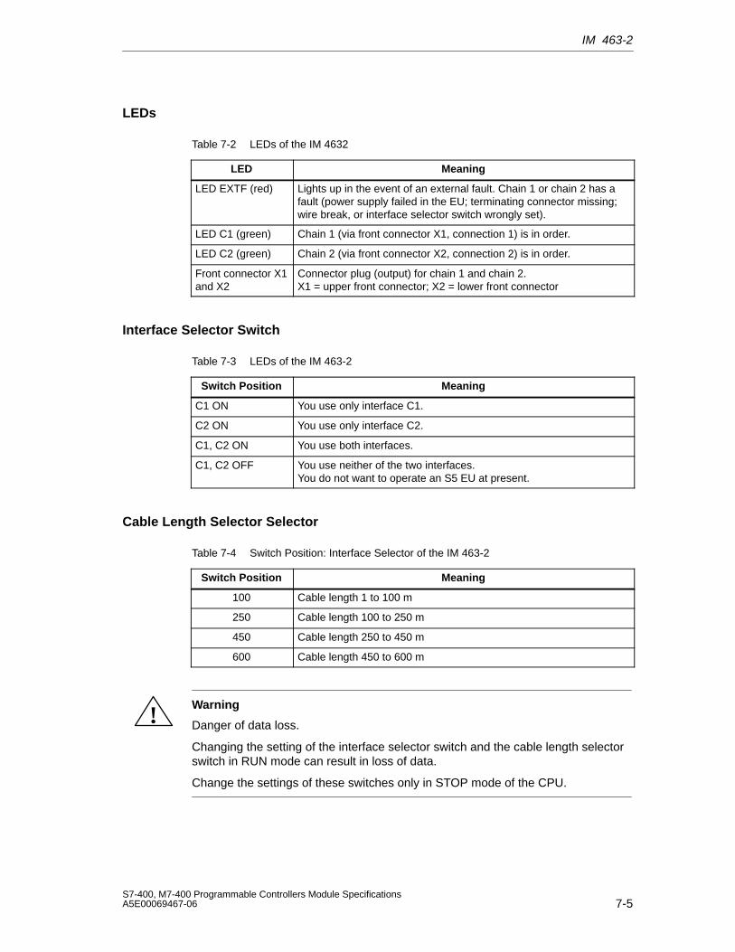
IM 463-2
7-5S7-400, M7-400 Programmable Controllers Module SpecificationsA5E00069467-06
LEDs
Table 7-2 LEDs of the IM 4632
LED Meaning
LED EXTF (red) Lights up in the event of an external fault. Chain 1 or chain 2 has afault (power supply failed in the EU; terminating connector missing;wire break, or interface selector switch wrongly set).
LED C1 (green) Chain 1 (via front connector X1, connection 1) is in order.
LED C2 (green) Chain 2 (via front connector X2, connection 2) is in order.
Front connector X1and X2
Connector plug (output) for chain 1 and chain 2.X1 = upper front connector; X2 = lower front connector
Interface Selector Switch
Table 7-3 LEDs of the IM 463-2
Switch Position Meaning
C1 ON You use only interface C1.
C2 ON You use only interface C2.
C1, C2 ON You use both interfaces.
C1, C2 OFF You use neither of the two interfaces.You do not want to operate an S5 EU at present.
Cable Length Selector Selector
Table 7-4 Switch Position: Interface Selector of the IM 463-2
Switch Position Meaning
100 Cable length 1 to 100 m
250 Cable length 100 to 250 m
450 Cable length 250 to 450 m
600 Cable length 450 to 600 m
!Warning
Danger of data loss.
Changing the setting of the interface selector switch and the cable length selectorswitch in RUN mode can result in loss of data.
Change the settings of these switches only in STOP mode of the CPU.
IM 463-2
7-6S7-400, M7-400 Programmable Controllers Module Specifications
A5E00069467-06
7.4 Installing and Connecting the IM 463-2
Introduction
To install an IM 463-2 in a CR of the S7-400, proceed in the same way as wheninstalling other S7-400 modules (see Installation Manual, Chapter 5).
To connect an IM 463-2, follow the steps outlined below:
1. Prepare the connecting cable
2. Plug in the connecting cable
3. Select the interface
4. Select the cable length
Preparing the Connecting Cable
You can use the 721 connecting cable. However, you must change the connectorhousing on the connection side of the IM 463-2.
Two connector housings are enclosed with every IM 463-2. You can prepare aconnecting cable for an IM 463-2 using one of these connector housings and a 721connecting cable (see Catalog ST 54.1). To prepare the connecting cable, followthe steps outlined below:
1. Remove one connector housing on the 721 connecting cable.
2. Open one of the connector housings enclosed with the IM 463-2.
3. Attach this connector housing to the 721 connecting cable.
4. Close the connector housing.
IM 463-2
7-7S7-400, M7-400 Programmable Controllers Module SpecificationsA5E00069467-06
Plugging in the Connecting Cable
To plug in the connecting cable, follow the steps outlined below:
1. Open the cover of the IM 463-2.
2. Plug the new connector of the connecting cable into one of the connectors ofthe IM 463-2.
Interface C1 corresponds to the upper connector; interface C2 corresponds tothe lower connector.
3. Screw the connector of the connecting cable onto the connector of theIM 463-2.
4. Close the cover.
Selecting the Interface
You select the interface with the selector switch on the front plate. Set theinterface(s) here that you want to use. Make the settings on the IM 463-2 onlywhen the CPU is in STOP mode.
Selecting the Cable Length
You select the cable length with the selector switch on the front plate. Set the rangecorresponding to the chain length. Make the settings on the IM 463-2 only whenthe CPU is in STOP mode.
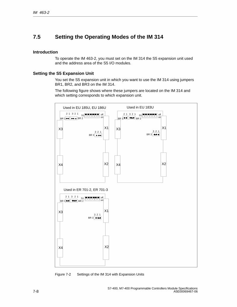
IM 463-2
7-8S7-400, M7-400 Programmable Controllers Module Specifications
A5E00069467-06
7.5 Setting the Operating Modes of the IM 314
IntroductionTo operate the IM 463-2, you must set on the IM 314 the S5 expansion unit usedand the address area of the S5 I/O modules.
Setting the S5 Expansion UnitYou set the S5 expansion unit in which you want to use the IM 314 using jumpersBR1, BR2, and BR3 on the IM 314.
The following figure shows where these jumpers are located on the IM 314 andwhich setting corresponds to which expansion unit.
••
•
BR 1 BR 1
•
BR 1
X3
X4
X1
X2
2 1 3 2 1S1 off
on
X3
X4
X1
X2
2 1 3 2 1 S1 offon
BR 33 2 1
X3
X4
X1
X2
BR 2
2 1 3 2 1S1 off
on
BR 33 2 1
•
BR 2 BR 2
••
••
••
• • •• • •••••
•BR 33 2 1
• •
Used in EU 185U, EU 186U Used in EU 183U
Used in ER 701-2, ER 701-3
Figure 7-2 Settings of the IM 314 with Expansion Units
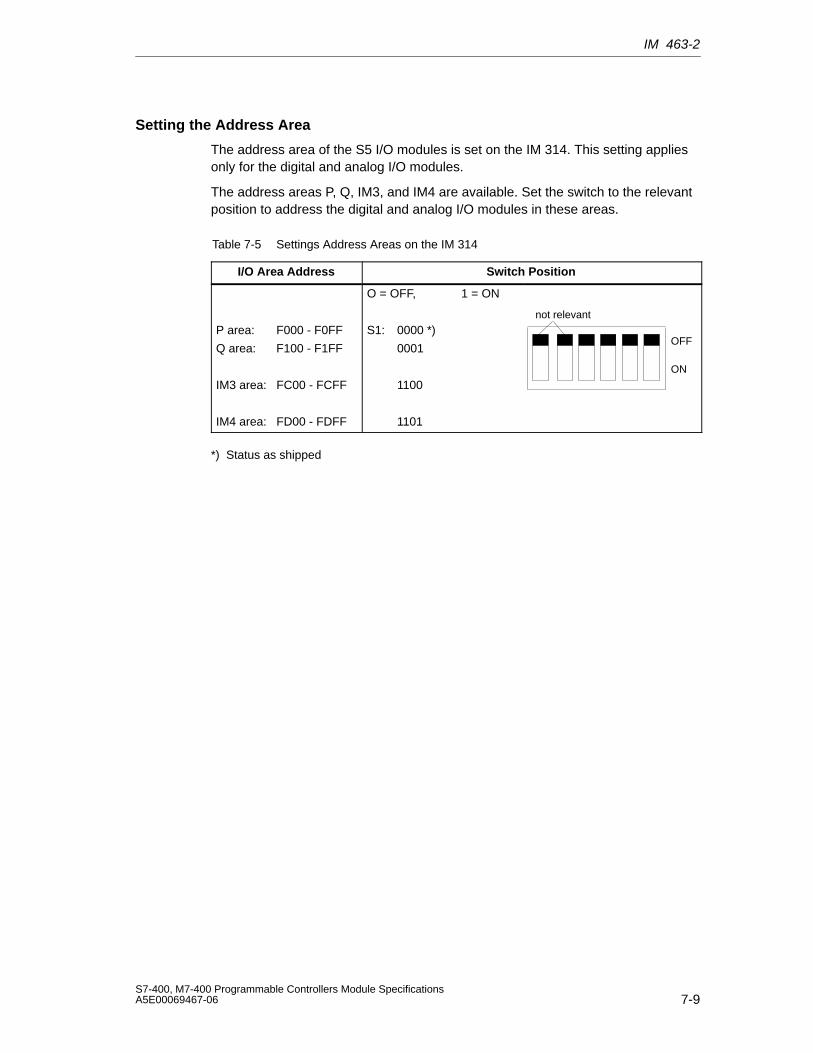
IM 463-2
7-9S7-400, M7-400 Programmable Controllers Module SpecificationsA5E00069467-06
Setting the Address Area
The address area of the S5 I/O modules is set on the IM 314. This setting appliesonly for the digital and analog I/O modules.
The address areas P, Q, IM3, and IM4 are available. Set the switch to the relevantposition to address the digital and analog I/O modules in these areas.
Table 7-5 Settings Address Areas on the IM 314
I/O Area Address Switch Position
P area: F000 - F0FF
Q area: F100 - F1FF
IM3 area: FC00 - FCFF
IM4 area: FD00 - FDFF
O = OFF, 1 = ON
S1: 0000 *)
0001
1100
1101
OFF
ON
not relevant
*) Status as shipped
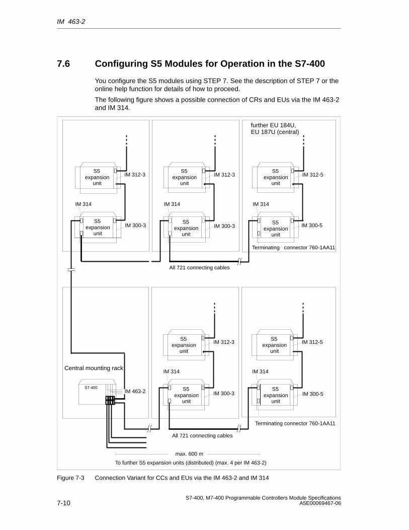
IM 463-2
7-10S7-400, M7-400 Programmable Controllers Module Specifications
A5E00069467-06
7.6 Configuring S5 Modules for Operation in the S7-400
You configure the S5 modules using STEP 7. See the description of STEP 7 or theonline help function for details of how to proceed.
The following figure shows a possible connection of CRs and EUs via the IM 463-2and IM 314.
IM 312-3
IM 300-3
IM 314
IM 312-3
IM 300-3
IM 314
IM 312-5
IM 314
All 721 connecting cables
further EU 184U,EU 187U (central)
IM 312-3
IM 300-3
IM 314
IM 312-5
IM 300-5
IM 314
Terminating connector 760-1AA11
All 721 connecting cables
To further S5 expansion units (distributed) (max. 4 per IM 463-2)
max. 600 m
S7-400
Central mounting rack
IM 300-5
IM 463-2
S5expansion
unit
Terminating connector 760-1AA11
S5expansion
unit
S5expansion
unit
S5expansion
unit
S5expansion
unit
S5expansion
unit
S5expansion
unit
S5expansion
unit
S5expansion
unit
S5expansion
unit
Figure 7-3 Connection Variant for CCs and EUs via the IM 463-2 and IM 314
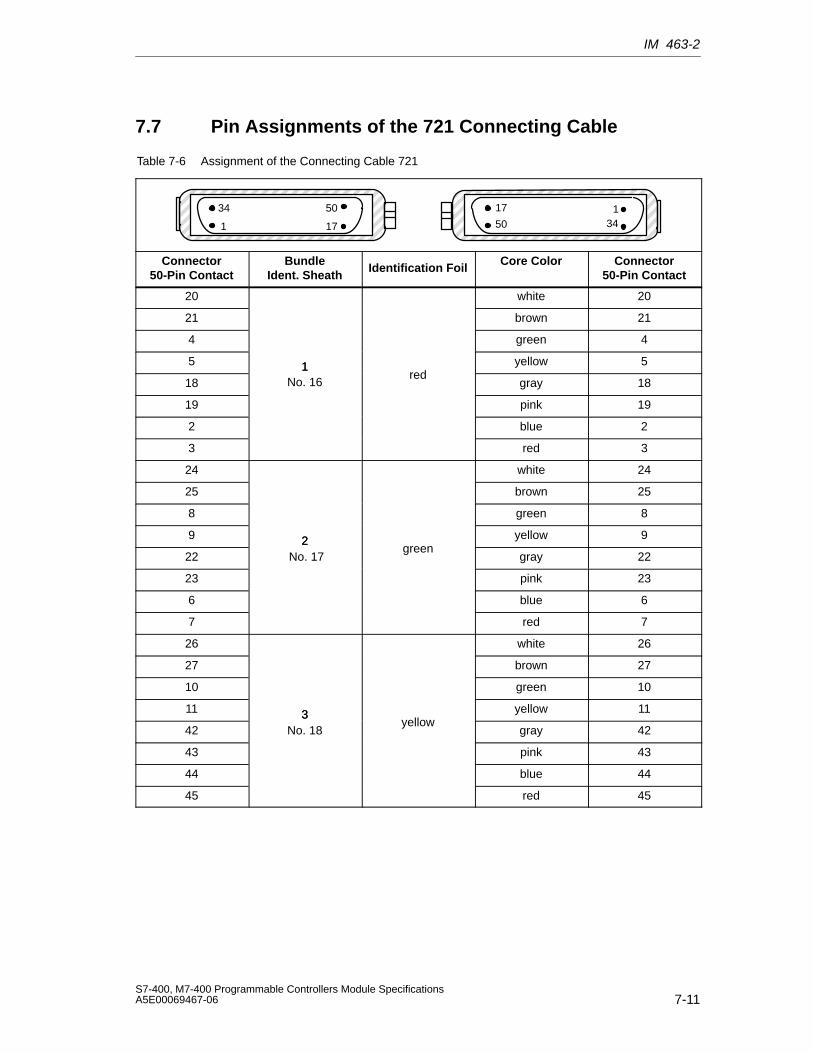
IM 463-2
7-11S7-400, M7-400 Programmable Controllers Module SpecificationsA5E00069467-06
7.7 Pin Assignments of the 721 Connecting Cable
Table 7-6 Assignment of the Connecting Cable 721
ÍÍÍÍÍÍÍÍÍÍÍÍÍÍÍÍÍÍÍÍÍÍÍÍÍÍÍÍÍÍÍÍÍ
3450
17 1ÍÍÍÍÍÍÍÍÍÍÍÍÍÍÍÍÍÍÍÍÍÍÍÍÍÍÍÍÍÍÍÍÍ
34 50
171
Connector50-Pin Contact
BundleIdent. Sheath
Identification Foil Core Color Connector50-Pin Contact
20 white 20
21 brown 21
4 green 4
5 1 yellow 5
181
No. 16red
gray 18
19 pink 19
2 blue 2
3 red 3
24 white 24
25 brown 25
8 green 8
9 2 yellow 9
222
No. 17green
gray 22
23 pink 23
6 blue 6
7 red 7
26 white 26
27 brown 27
10 green 10
11 3 yellow 11
423
No. 18yellow
gray 42
43 pink 43
44 blue 44
45 red 45
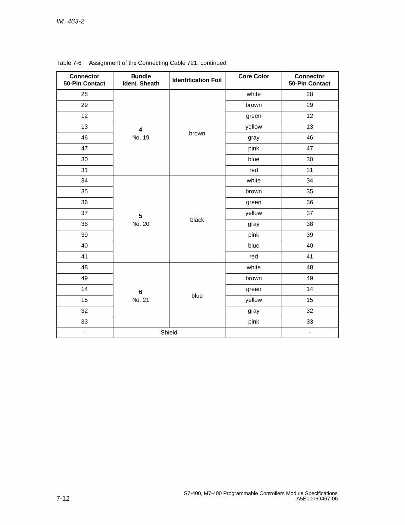
IM 463-2
7-12S7-400, M7-400 Programmable Controllers Module Specifications
A5E00069467-06
Table 7-6 Assignment of the Connecting Cable 721, continued
Connector50-Pin Contact
Connector50-Pin Contact
Core ColorIdentification Foil
BundleIdent. Sheath
28 white 28
29 brown 29
12 green 12
13 4 yellow 13
464
No. 19brown
gray 46
47 pink 47
30 blue 30
31 red 31
34 white 34
35 brown 35
36 green 36
37 5 yellow 37
385
No. 20black
gray 38
39 pink 39
40 blue 40
41 red 41
48 white 48
49 brown 49
14 6 green 14
156
No. 21blue
yellow 15
32 gray 32
33 pink 33
- Shield -
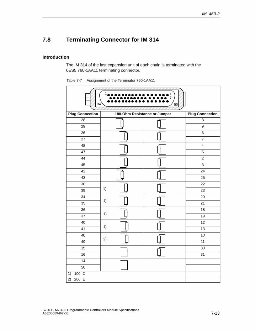
IM 463-2
7-13S7-400, M7-400 Programmable Controllers Module SpecificationsA5E00069467-06
7.8 Terminating Connector for IM 314
Introduction
The IM 314 of the last expansion unit of each chain is terminated with the6ES5 760-1AA11 terminating connector.
Table 7-7 Assignment of the Terminator 760-1AA11
ÍÍÍÍÍÍÍÍÍÍÍÍÍÍÍÍÍÍÍÍÍÍÍÍÍÍÍÍÍÍÍÍÍÍÍÍÍÍÍÍÍÍÍÍÍÍÍÍÍÍÍÍÍÍÍÍÍÍÍÍÍÍÍÍÍÍÍÍÍÍÍÍÍÍÍ
34 50
17
1
Plug Connection 180-Ohm Resistance or Jumper Plug Connection
28 8
29 9
26 6
27 7
48 4
47 5
44 2
45 3
42 24
43 25
38 22
39 1) 23
34 20
351)
21
36 18
37 1) 19
40 12
41 1) 13
48 10
492)
11
15 30
16 31
14
50
1) 100
2) 200
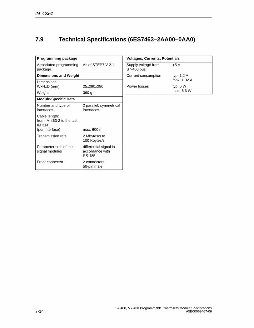
IM 463-2
7-14S7-400, M7-400 Programmable Controllers Module Specifications
A5E00069467-06
7.9 Technical Specifications (6ES7463–2AA00–0AA0)
Programming package
Associated programmingpackage
As of STEP7 V 2.1
Dimensions and Weight
Dimensions WxHxD (mm) 25x290x280
Weight 360 g
Module-Specific Data
Number and type ofinterfaces
2 parallel, symmetricalinterfaces
Cable length:from IM 463-2 to the lastIM 314 (per interface) max. 600 m
Transmission rate 2 Mbytes/s to100 Kbytes/s
Parameter sets of thesignal modules
differential signal inaccordance withRS 485
Front connector 2 connectors,50-pin male
Voltages, Currents, Potentials
Supply voltage fromS7-400 bus
+5 V
Current consumption typ. 1.2 Amax. 1.32 A
Power losses typ. 6 Wmax. 6.6 W
8-1S7-400, M7-400 Programmable Controllers Module SpecificationsA5E00069467-06
PROFIBUS DP Master InterfaceIM 467/IM 467 FO
Chapter Overview
Section Description Page
8.1 PROFIBUS DP Master Interface IM 467/IM 467 FO 8-2
8.2 Configuration 8-6
8.3 Connection to PROFIBUS DP 8-8
8.4 Technical Specifications 8-12
8
PROFIBUS DP Master Interface IM 467/IM 467 FO
8-2S7-400, M7-400 Programmable Controllers Module Specifications
A5E00069467-06
8.1 PROFIBUS DP Master Interface IM 467/IM 467 FO
Order Numbers
IM 467 6ES7467-5GJ02-0AB0 (RS 485)
IM 467 FO 6ES7467-5FJ00-0AB0 (F0)
Application
PROFIBUS DP, standardized to IEC 61784–1:2002 Ed1 CP 3/1, enables rapidcommunication in the field between programmable controllers, PCs and fielddevices. Field devices are devices such as: ET 200 distributed I/O devices, drives,valve terminals, switchgear and many others.
The IM 467/IM 467 FO interface module is meant to be used in an S7-400programmable controller. It permits the S7-400 to be connected to PROFIBUS DP.
Note
The PROFIBUS DP master interface IM 467 or IM 467 FO is not a DP master in accordance with DPV 1.
Configuration
• Configured as for the S7-400
• Can be operated without a fan
• A maximum of 4 IM 467/IM 467 FO can be used in the central controller. Thereare no slot rules.
• The IM 467/IM 467 FO and the CP 443-5 Extended cannot be used together.
• The transmission rate of 9.6 kbps to 12 Mbps can be set in steps using software
• Configuration and programming are possible via PROFIBUS DP. You must not, however, change the PROFIBUS DP parameters.
• IM 467 with 9-pin subminiature D female connector for connection toPROFIBUS DP (6ES7467-5GJ02-0AB0)
• IM 467 FO with fiber-optic cable for connection toPROFIBUS DP (6ES7467-5FJ00-0AB0)
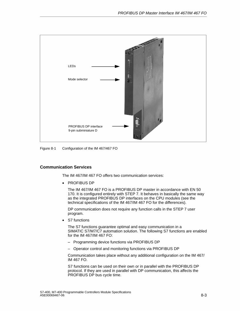
PROFIBUS DP Master Interface IM 467/IM 467 FO
8-3S7-400, M7-400 Programmable Controllers Module SpecificationsA5E00069467-06
PROFIBUS DP interface9-pin subminiature D
LEDs
Mode selector
Figure 8-1 Configuration of the IM 467/467 FO
Communication Services
The IM 467/IM 467 FO offers two communication services:
• PROFIBUS DP
The IM 467/IM 467 FO is a PROFIBUS DP master in accordance with EN 50170. It is configured entirely with STEP 7. It behaves in basically the same wayas the integrated PROFIBUS DP interfaces on the CPU modules (see thetechnical specifications of the IM 467/IM 467 FO for the differences).
DP communication does not require any function calls in the STEP 7 userprogram.
• S7 functions
The S7 functions guarantee optimal and easy communication in aSIMATIC S7/M7/C7 automation solution. The following S7 functions are enabledfor the IM 467/IM 467 FO:
– Programming device functions via PROFIBUS DP
– Operator control and monitoring functions via PROFIBUS DP
Communication takes place without any additional configuration on the IM 467/IM 467 FO.
S7 functions can be used on their own or in parallel with the PROFIBUS DPprotocol. If they are used in parallel with DP communication, this affects thePROFIBUS DP bus cycle time.
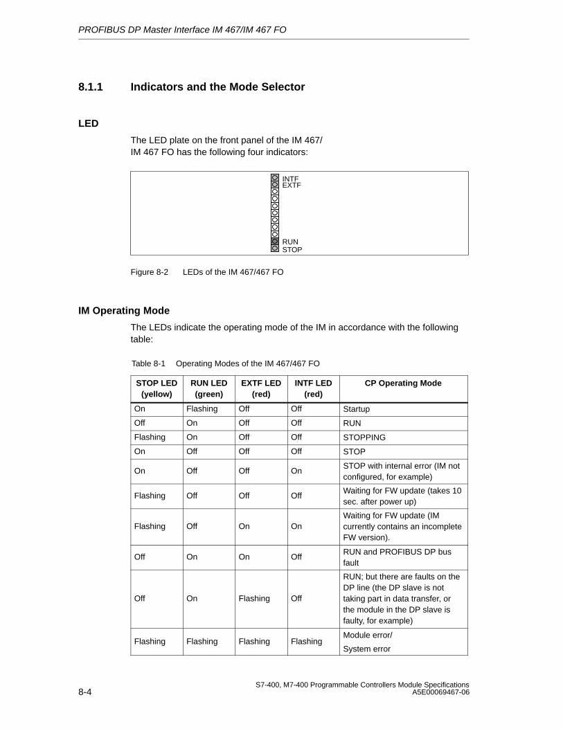
PROFIBUS DP Master Interface IM 467/IM 467 FO
8-4S7-400, M7-400 Programmable Controllers Module Specifications
A5E00069467-06
8.1.1 Indicators and the Mode Selector
LED
The LED plate on the front panel of the IM 467/IM 467 FO has the following four indicators:
INTFEXTF
RUNSTOP
Figure 8-2 LEDs of the IM 467/467 FO
IM Operating Mode
The LEDs indicate the operating mode of the IM in accordance with the followingtable:
Table 8-1 Operating Modes of the IM 467/467 FO
STOP LED(yellow)
RUN LED(green)
EXTF LED(red)
INTF LED(red)
CP Operating Mode
On Flashing Off Off Startup
Off On Off Off RUN
Flashing On Off Off STOPPING
On Off Off Off STOP
On Off Off OnSTOP with internal error (IM notconfigured, for example)
Flashing Off Off OffWaiting for FW update (takes 10sec. after power up)
Flashing Off On OnWaiting for FW update (IMcurrently contains an incompleteFW version).
Off On On OffRUN and PROFIBUS DP busfault
Off On Flashing Off
RUN; but there are faults on theDP line (the DP slave is nottaking part in data transfer, orthe module in the DP slave isfaulty, for example)
Flashing Flashing Flashing FlashingModule error/
System error
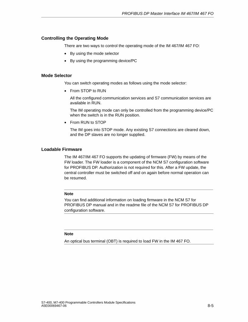
PROFIBUS DP Master Interface IM 467/IM 467 FO
8-5S7-400, M7-400 Programmable Controllers Module SpecificationsA5E00069467-06
Controlling the Operating Mode
There are two ways to control the operating mode of the IM 467/IM 467 FO:
• By using the mode selector
• By using the programming device/PC
Mode Selector
You can switch operating modes as follows using the mode selector:
• From STOP to RUN
All the configured communication services and S7 communication services areavailable in RUN.
The IM operating mode can only be controlled from the programming device/PCwhen the switch is in the RUN position.
• From RUN to STOP
The IM goes into STOP mode. Any existing S7 connections are cleared down,and the DP slaves are no longer supplied.
Loadable Firmware
The IM 467/IM 467 FO supports the updating of firmware (FW) by means of theFW loader. The FW loader is a component of the NCM S7 configuration softwarefor PROFIBUS DP. Authorization is not required for this. After a FW update, thecentral controller must be switched off and on again before normal operation canbe resumed.
Note
You can find additional information on loading firmware in the NCM S7 forPROFIBUS DP manual and in the readme file of the NCM S7 for PROFIBUS DPconfiguration software.
Note
An optical bus terminal (OBT) is required to load FW in the IM 467 FO.
PROFIBUS DP Master Interface IM 467/IM 467 FO
8-6S7-400, M7-400 Programmable Controllers Module Specifications
A5E00069467-06
8.2 Configuration
The IM 467/IM 467 FO is configured with STEP 7. The configuration data areretained even in the event of a power failure; a memory module is not required.Using the S7 functions it is possible to program and configure remotely all theIM 467/IM 467 FO connected to the network and all the CPUs connected via theSIMATIC S7-400 backplane bus.
SIMATIC STEP 7 is the prerequisite for this.
• STEP 7 V3.1
The IM 467 (MLFB no. 6ES7467-5GJ00-0AB0) can be configured as of STEP 7version 3.1.
• STEP 7 V4.02
The IM 467 (MLFB no. 6ES7467-5GJ01-0AB0) supports the SYNC/FREEZEfunctional enhancement as of STEP 7 version 4.02.
• STEP 7 as of version 5.00
The IM 467/IM 467 FO (MLFB number6ES7467-5GJ02-0AB0/6ES7467-5FJ00-0AB0) supports the functionalexpansions of routing of programming device functions, DP directcommunication and equidistance as of STEP 7 version 5.00.
Module Replacement Without a Programming Device
The configuration data are stored in the load memory of the CPU. The non-volatilestorage of configuration data in the CPU is ensured by battery backup or EPROMmodule cards.
The IM 467/IM 467 FO can be replaced without the need to explicitly reload theconfiguration data.
It is only possible to remove and insert the IM 467/IM 467 FO in a deenergizedstate.
Multiprocessor Operation
The connected DP slaves can only be assigned to and processed by one CPU.
Configuration and Diagnostics Cannot Be Carried Out Simultaneously
When configuration is in progress, the IM 467/IM 467 FO cannot be diagnosed atthe same time via MPI.
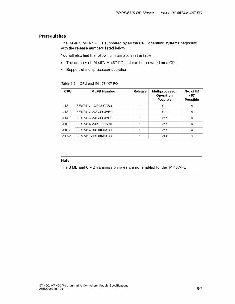
PROFIBUS DP Master Interface IM 467/IM 467 FO
8-7S7-400, M7-400 Programmable Controllers Module SpecificationsA5E00069467-06
Prerequisites
The IM 467/IM 467 FO is supported by all the CPU operating systems beginningwith the release numbers listed below.
You will also find the following information in the table:
• The number of IM 467/IM 467 FO that can be operated on a CPU
• Support of multiprocessor operation
Table 8-2 CPU and IM 467/467 FO
CPU MLFB Number Release MultiprocessorOperationPossible
No. of IM467
Possible
412 6ES7412-1XF03-0AB0 1 Yes 4
412-2 6ES7412-2XG00-0AB0 1 Yes 4
414-2 6ES7414-2XG03-0AB0 1 Yes 4
416-2 6ES7416-2XK02-0AB0 1 Yes 4
416-3 6ES7414-3XL00-0AB0 1 Yes 4
417-4 6ES7417-4XL00-0AB0 1 Yes 4
Note
The 3 MB and 6 MB transmission rates are not enabled for the IM 467-FO.
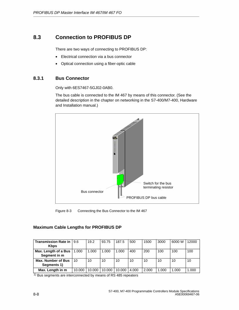
PROFIBUS DP Master Interface IM 467/IM 467 FO
8-8S7-400, M7-400 Programmable Controllers Module Specifications
A5E00069467-06
8.3 Connection to PROFIBUS DP
There are two ways of connecting to PROFIBUS DP:
• Electrical connection via a bus connector
• Optical connection using a fiber-optic cable
8.3.1 Bus Connector
Only with 6ES7467-5GJ02-0AB0.
The bus cable is connected to the IM 467 by means of this connector. (See thedetailed description in the chapter on networking in the S7-400/M7-400, Hardwareand Installation manual.)
Bus connector
PROFIBUS DP bus cable
Switch for the busterminating resistor
Figure 8-3 Connecting the Bus Connector to the IM 467
Maximum Cable Lengths for PROFIBUS DP
Transmission Rate inKbps
9.6 19.2 93.75 187.5 500 1500 3000 6000 W 12000
Max. Length of a BusSegment in m
1.000 1.000 1.000 1.000 400 200 100 100 100
Max. Number of BusSegments 1)
10 10 10 10 10 10 10 10 10
Max. Length in m 10.000 10.000 10.000 10.000 4.000 2.000 1.000 1.000 1.0001) Bus segments are interconnected by means of RS 485 repeaters
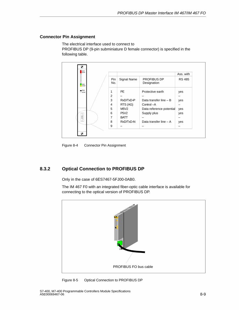
PROFIBUS DP Master Interface IM 467/IM 467 FO
8-9S7-400, M7-400 Programmable Controllers Module SpecificationsA5E00069467-06
Connector Pin Assignment
The electrical interface used to connect to PROFIBUS DP (9-pin subminiature D female connector) is specified in thefollowing table.
123456789
PE–RxD/TxD–PRTS (AG)M5V2P5V2BATTRxD/TxD–N–
Protective earth
Data transfer line – BControl –AData reference potentialSupply plus–Data transfer line – A–
yes
–yesyes–yes–
– –yes
RUN
RUN
STOP
STOP
INTFEXTF
PinNo.
Signal Name PROFIBUS DP Designation
Ass. with
RS 485
Figure 8-4 Connector Pin Assignment
8.3.2 Optical Connection to PROFIBUS DP
Only in the case of 6ES7467-5FJ00-0AB0.
The IM 467 F0 with an integrated fiber-optic cable interface is available forconnecting to the optical version of PROFIBUS DP.
CP443–5443–5FX00–0XE0
STOPRUN
INTFEXTF
RUNSTOP
AUI/TP
X234
PROFIBUS FO bus cable
Figure 8-5 Optical Connection to PROFIBUS DP
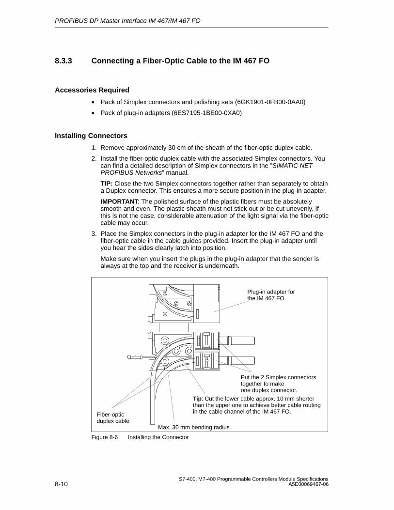
PROFIBUS DP Master Interface IM 467/IM 467 FO
8-10S7-400, M7-400 Programmable Controllers Module Specifications
A5E00069467-06
8.3.3 Connecting a Fiber-Optic Cable to the IM 467 FO
Accessories Required
• Pack of Simplex connectors and polishing sets (6GK1901-0FB00-0AA0)
• Pack of plug-in adapters (6ES7195-1BE00-0XA0)
Installing Connectors
1. Remove approximately 30 cm of the sheath of the fiber-optic duplex cable.
2. Install the fiber-optic duplex cable with the associated Simplex connectors. Youcan find a detailed description of Simplex connectors in the ”SIMATIC NETPROFIBUS Networks” manual.
TIP: Close the two Simplex connectors together rather than separately to obtaina Duplex connector. This ensures a more secure position in the plug-in adapter.
IMPORTANT: The polished surface of the plastic fibers must be absolutelysmooth and even. The plastic sheath must not stick out or be cut unevenly. Ifthis is not the case, considerable attenuation of the light signal via the fiber-opticcable may occur.
3. Place the Simplex connectors in the plug-in adapter for the IM 467 FO and thefiber-optic cable in the cable guides provided. Insert the plug-in adapter untilyou hear the sides clearly latch into position.
Make sure when you insert the plugs in the plug-in adapter that the sender isalways at the top and the receiver is underneath.
Fiber-optic duplex cable
Max. 30 mm bending radius
Plug-in adapter forthe IM 467 FO
Put the 2 Simplex connectorstogether to makeone duplex connector.
Tip: Cut the lower cable approx. 10 mm shorterthan the upper one to achieve better cable routingin the cable channel of the IM 467 FO.
Figure 8-6 Installing the Connector
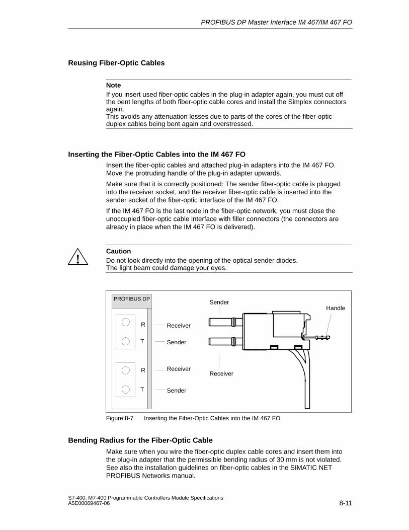
PROFIBUS DP Master Interface IM 467/IM 467 FO
8-11S7-400, M7-400 Programmable Controllers Module SpecificationsA5E00069467-06
Reusing Fiber-Optic Cables
NoteIf you insert used fiber-optic cables in the plug-in adapter again, you must cut offthe bent lengths of both fiber-optic cable cores and install the Simplex connectorsagain.This avoids any attenuation losses due to parts of the cores of the fiber-opticduplex cables being bent again and overstressed.
Inserting the Fiber-Optic Cables into the IM 467 FOInsert the fiber-optic cables and attached plug-in adapters into the IM 467 FO.Move the protruding handle of the plug-in adapter upwards.
Make sure that it is correctly positioned: The sender fiber-optic cable is pluggedinto the receiver socket, and the receiver fiber-optic cable is inserted into thesender socket of the fiber-optic interface of the IM 467 FO.
If the IM 467 FO is the last node in the fiber-optic network, you must close theunoccupied fiber-optic cable interface with filler connectors (the connectors arealready in place when the IM 467 FO is delivered).
!CautionDo not look directly into the opening of the optical sender diodes.The light beam could damage your eyes.
HandleSender
Receiver
PROFIBUS DP
Receiver
Receiver
Sender
Sender
R
T
R
T
Figure 8-7 Inserting the Fiber-Optic Cables into the IM 467 FO
Bending Radius for the Fiber-Optic Cable
Make sure when you wire the fiber-optic duplex cable cores and insert them intothe plug-in adapter that the permissible bending radius of 30 mm is not violated.See also the installation guidelines on fiber-optic cables in the SIMATIC NETPROFIBUS Networks manual.
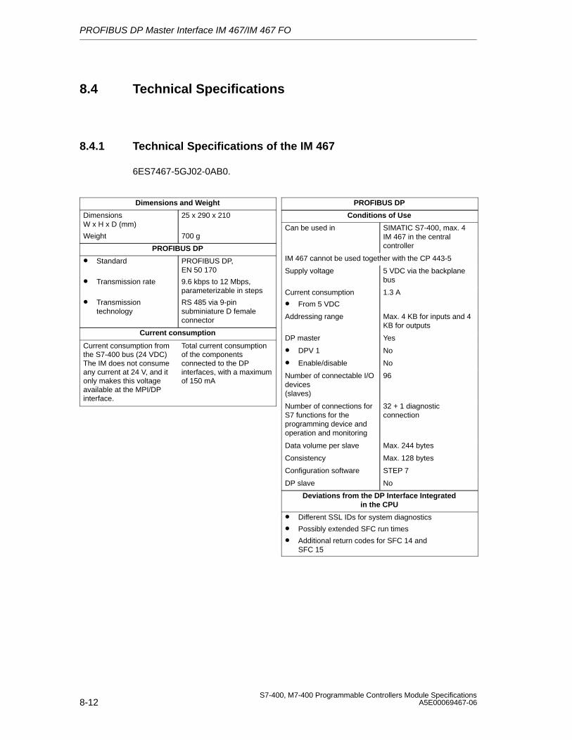
PROFIBUS DP Master Interface IM 467/IM 467 FO
8-12S7-400, M7-400 Programmable Controllers Module Specifications
A5E00069467-06
8.4 Technical Specifications
8.4.1 Technical Specifications of the IM 467
6ES7467-5GJ02-0AB0.
Dimensions and Weight
Dimensions W x H x D (mm)
Weight
25 x 290 x 210
700 g
PROFIBUS DP
• Standard
• Transmission rate
• Transmissiontechnology
PROFIBUS DP, EN 50 170
9.6 kbps to 12 Mbps,parameterizable in steps
RS 485 via 9-pinsubminiature D femaleconnector
Current consumption
Current consumption fromthe S7-400 bus (24 VDC)The IM does not consumeany current at 24 V, and itonly makes this voltageavailable at the MPI/DPinterface.
Total current consumptionof the componentsconnected to the DPinterfaces, with a maximumof 150 mA
PROFIBUS DP
Conditions of Use
Can be used in SIMATIC S7-400, max. 4IM 467 in the centralcontroller
IM 467 cannot be used together with the CP 443-5
Supply voltage 5 VDC via the backplanebus
Current consumption
• From 5 VDC
1.3 A
Addressing range Max. 4 KB for inputs and 4KB for outputs
DP master Yes
• DPV 1 No
• Enable/disable No
Number of connectable I/Odevices (slaves)
96
Number of connections forS7 functions for theprogramming device andoperation and monitoring
32 + 1 diagnosticconnection
Data volume per slave Max. 244 bytes
Consistency Max. 128 bytes
Configuration software STEP 7
DP slave No
Deviations from the DP Interface Integratedin the CPU
• Different SSL IDs for system diagnostics
• Possibly extended SFC run times
• Additional return codes for SFC 14 and SFC 15
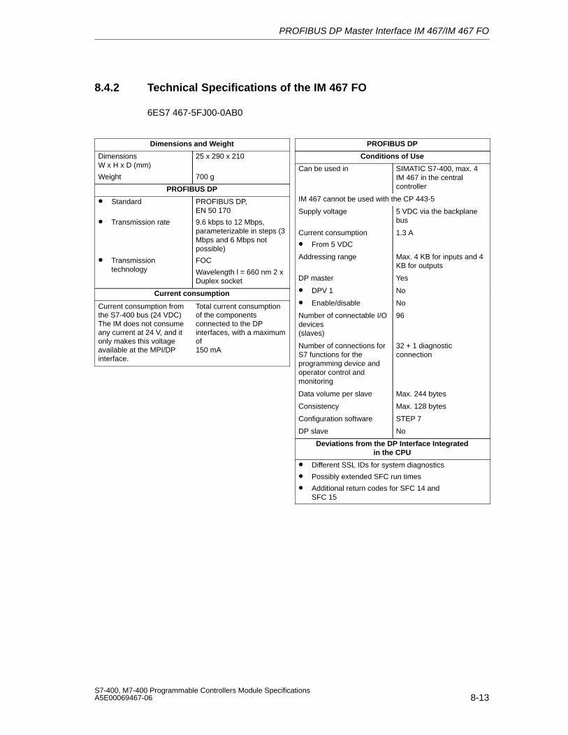
PROFIBUS DP Master Interface IM 467/IM 467 FO
8-13S7-400, M7-400 Programmable Controllers Module SpecificationsA5E00069467-06
8.4.2 Technical Specifications of the IM 467 FO
6ES7 467-5FJ00-0AB0
Dimensions and Weight
Dimensions W x H x D (mm)
Weight
25 x 290 x 210
700 g
PROFIBUS DP
• Standard
• Transmission rate
• Transmissiontechnology
PROFIBUS DP, EN 50 170
9.6 kbps to 12 Mbps,parameterizable in steps (3Mbps and 6 Mbps notpossible)
FOC
Wavelength l = 660 nm 2 xDuplex socket
Current consumption
Current consumption fromthe S7-400 bus (24 VDC)The IM does not consumeany current at 24 V, and itonly makes this voltageavailable at the MPI/DPinterface.
Total current consumptionof the componentsconnected to the DPinterfaces, with a maximumof 150 mA
PROFIBUS DP
Conditions of Use
Can be used in SIMATIC S7-400, max. 4IM 467 in the centralcontroller
IM 467 cannot be used with the CP 443-5
Supply voltage 5 VDC via the backplanebus
Current consumption
• From 5 VDC
1.3 A
Addressing range Max. 4 KB for inputs and 4KB for outputs
DP master Yes
• DPV 1 No
• Enable/disable No
Number of connectable I/Odevices (slaves)
96
Number of connections forS7 functions for theprogramming device andoperator control andmonitoring
32 + 1 diagnosticconnection
Data volume per slave Max. 244 bytes
Consistency Max. 128 bytes
Configuration software STEP 7
DP slave No
Deviations from the DP Interface Integratedin the CPU
• Different SSL IDs for system diagnostics
• Possibly extended SFC run times
• Additional return codes for SFC 14 and SFC 15

PROFIBUS DP Master Interface IM 467/IM 467 FO
8-14S7-400, M7-400 Programmable Controllers Module Specifications
A5E00069467-06
9-1S7-400, M7-400 Programmable Controllers Module SpecificationsA5E00069467-06
Cable Duct and Fan Subassemblies
Chapter Overview
Section Description Page
9.1 Fan Monitoring in the Fan Subassemblies 9-2
9.2 Cable Duct; (6ES7408-0TA00-0AA0) 9-4
9.3 The 120/230 VAC Fan Subassembly; (6ES7408-1TB00-0XA0) 9-5
9.4 The 24 VDC Fan Subassembly; (6ES7408-1TA00-0XA0) 9-7
Characteristics
The cable duct and the fan subassembly have the following characteristics
• The air inflow area is variable.
• Shield and cable clamping are possible.
In addition, the fan subassembly has the following characteristics:
• Fans and filter frames can be replaced from the front during operation.
• The fan function is controlled by means of speed monitoring.
• Operation with filter frames is optional.
9
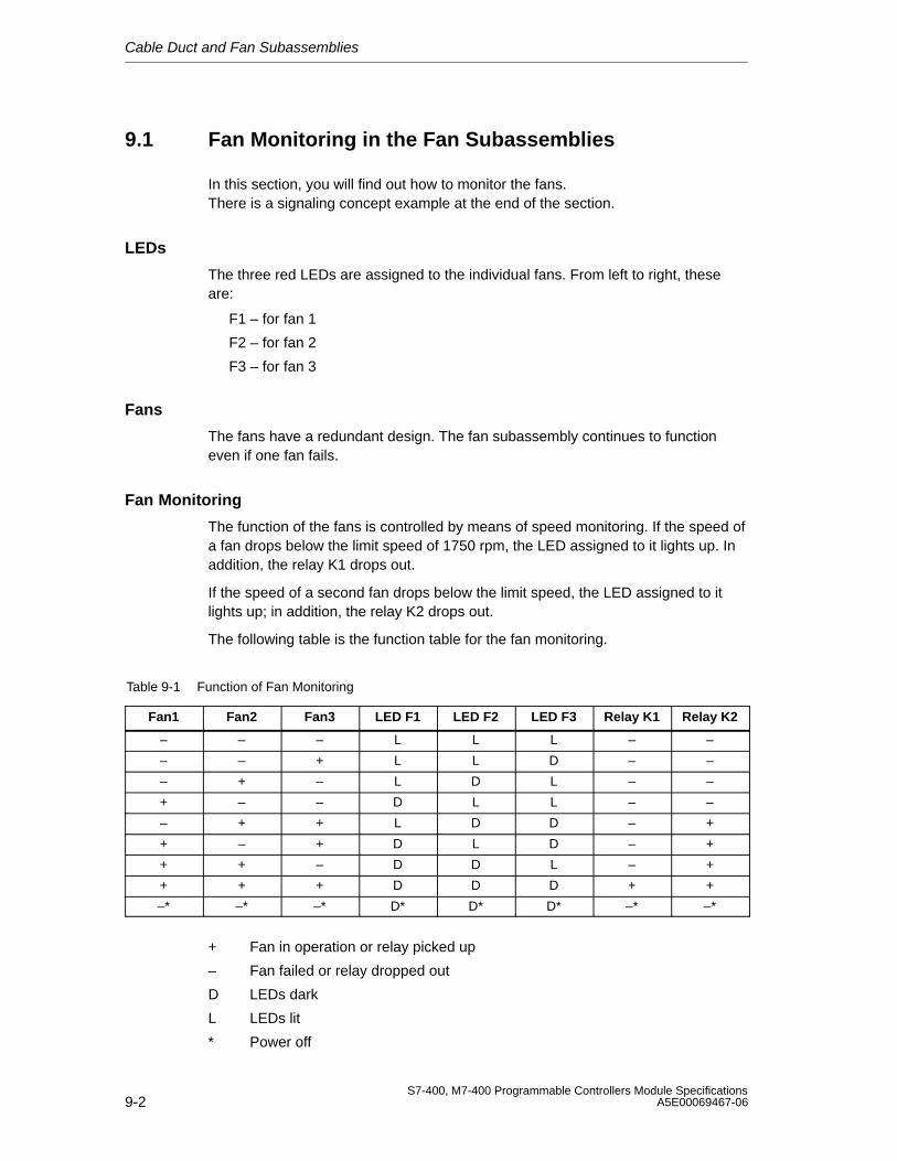
Cable Duct and Fan Subassemblies
9-2S7-400, M7-400 Programmable Controllers Module Specifications
A5E00069467-06
9.1 Fan Monitoring in the Fan Subassemblies
In this section, you will find out how to monitor the fans. There is a signaling concept example at the end of the section.
LEDs
The three red LEDs are assigned to the individual fans. From left to right, theseare:
F1 – for fan 1
F2 – for fan 2
F3 – for fan 3
Fans
The fans have a redundant design. The fan subassembly continues to functioneven if one fan fails.
Fan Monitoring
The function of the fans is controlled by means of speed monitoring. If the speed ofa fan drops below the limit speed of 1750 rpm, the LED assigned to it lights up. Inaddition, the relay K1 drops out.
If the speed of a second fan drops below the limit speed, the LED assigned to itlights up; in addition, the relay K2 drops out.
The following table is the function table for the fan monitoring.
Table 9-1 Function of Fan Monitoring
Fan1 Fan2 Fan3 LED F1 LED F2 LED F3 Relay K1 Relay K2
– – – L L L – –
– – + L L D – –
– + – L D L – –
+ – – D L L – –
– + + L D D – +
+ – + D L D – +
+ + – D D L – +
+ + + D D D + +
–* –* –* D* D* D* –* –*
+ Fan in operation or relay picked up
– Fan failed or relay dropped out
D LEDs dark
L LEDs lit
* Power off
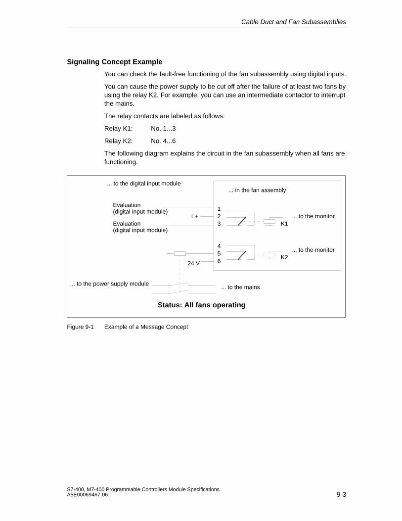
Cable Duct and Fan Subassemblies
9-3S7-400, M7-400 Programmable Controllers Module SpecificationsA5E00069467-06
Signaling Concept Example
You can check the fault-free functioning of the fan subassembly using digital inputs.
You can cause the power supply to be cut off after the failure of at least two fans byusing the relay K2. For example, you can use an intermediate contactor to interruptthe mains.
The relay contacts are labeled as follows:
Relay K1: No. 1...3
Relay K2: No. 4...6
The following diagram explains the circuit in the fan subassembly when all fans arefunctioning.
654
321
L+ ... to the monitor
... to the monitor
... to the digital input module
24 V
... to the mains... to the power supply module
... in the fan assembly
K1
K2
Evaluation(digital input module)
Evaluation(digital input module)
Status: All fans operating
Figure 9-1 Example of a Message Concept
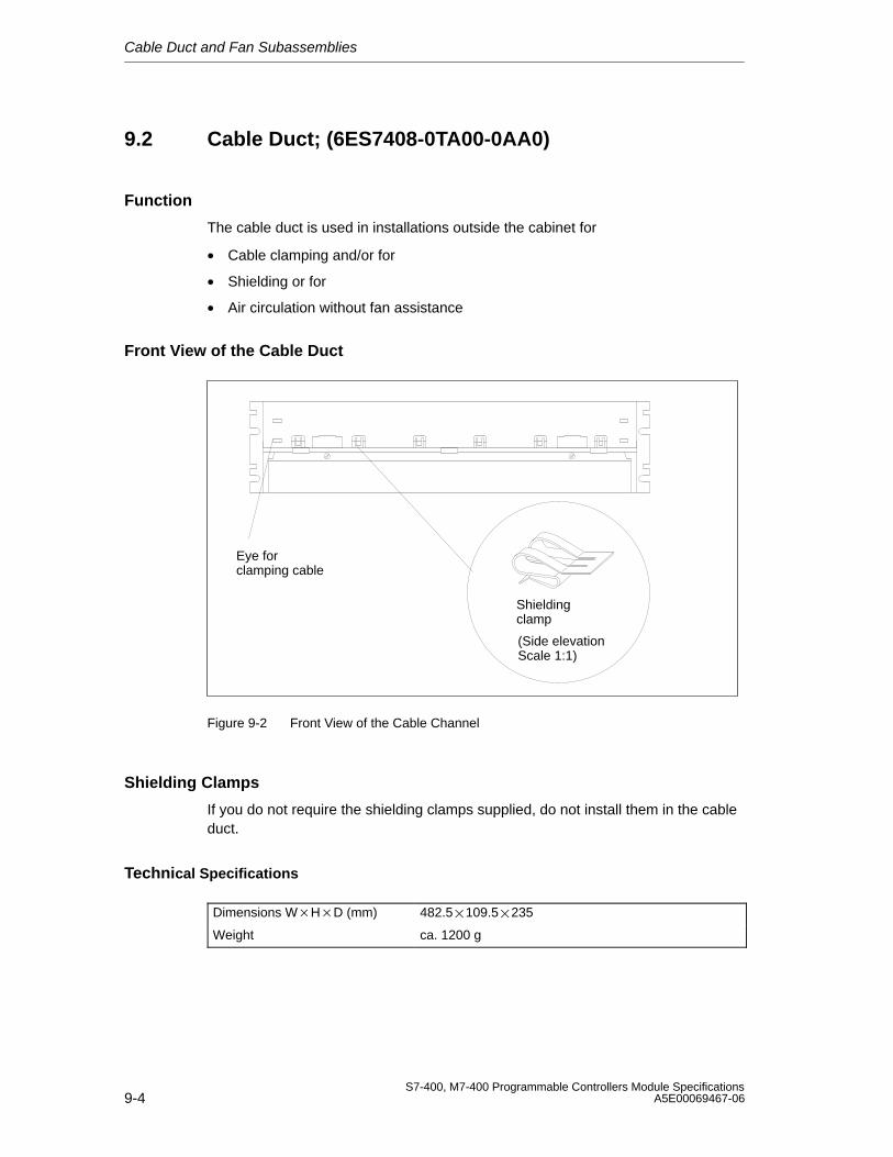
Cable Duct and Fan Subassemblies
9-4S7-400, M7-400 Programmable Controllers Module Specifications
A5E00069467-06
9.2 Cable Duct; (6ES7408-0TA00-0AA0)
Function
The cable duct is used in installations outside the cabinet for
• Cable clamping and/or for
• Shielding or for
• Air circulation without fan assistance
Front View of the Cable Duct
Shieldingclamp
(Side elevationScale 1:1)
Eye forclamping cable
Figure 9-2 Front View of the Cable Channel
Shielding Clamps
If you do not require the shielding clamps supplied, do not install them in the cableduct.
Technical Specifications
Dimensions WHD (mm) 482.5109.5235
Weight ca. 1200 g
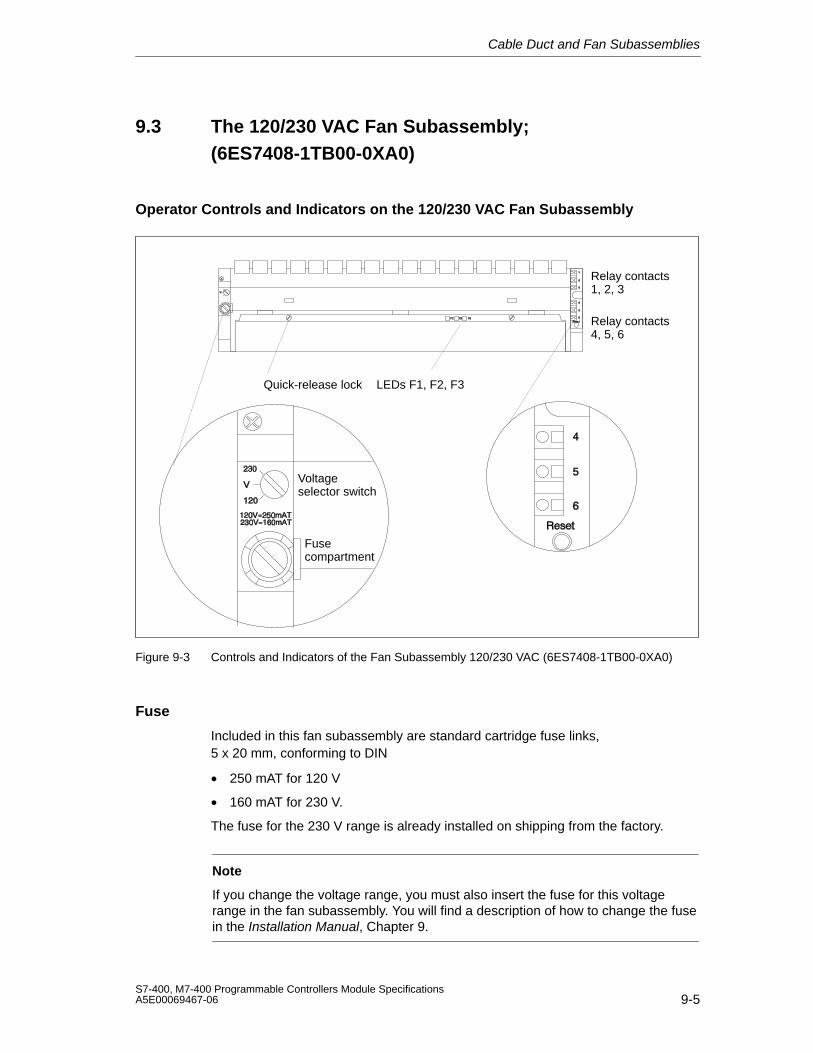
Cable Duct and Fan Subassemblies
9-5S7-400, M7-400 Programmable Controllers Module SpecificationsA5E00069467-06
9.3 The 120/230 VAC Fan Subassembly;(6ES7408-1TB00-0XA0)
Operator Controls and Indicators on the 120/230 VAC Fan Subassembly
LEDs F1, F2, F3Quick-release lock
Relay contacts 1, 2, 3
Relay contacts4, 5, 6
Voltageselector switch
Fusecompartment
Figure 9-3 Controls and Indicators of the Fan Subassembly 120/230 VAC (6ES7408-1TB00-0XA0)
Fuse
Included in this fan subassembly are standard cartridge fuse links, 5 x 20 mm, conforming to DIN
• 250 mAT for 120 V
• 160 mAT for 230 V.
The fuse for the 230 V range is already installed on shipping from the factory.
Note
If you change the voltage range, you must also insert the fuse for this voltagerange in the fan subassembly. You will find a description of how to change the fusein the Installation Manual, Chapter 9.
Cable Duct and Fan Subassemblies
9-6S7-400, M7-400 Programmable Controllers Module Specifications
A5E00069467-06
Shielding Clamps
If you do not require the shielding clamps supplied, do not install them in the fansubassembly.
Technical SpecificationsDimensions, Weights
Dimensions WxHxD (mm) 482.5×109.5×235
Weight appr. 2000 g
Cable diameter 3 bis 9 mm
Nominal Sizes
Lifespan of the fans
• at C
• at C
70000 h
25000 h
Max. contact load of relaycontacts 1 to 6
• Switching voltage
• Switching current
24 VDC
200 mA
Voltages, Currents, Potentials
At nominal voltage of 230 VAC 120 VAC
Power consumption
• with fan
• without fan
17 W 18 W
5 W 4 W
Starting current 0,6 A 1,15 A
Fuses 160 mA 250 mA
!Warning
Electrical current can lead to personal injury.
If you remove the left cover when installing or removing the fan subassembly, theterminals on the transformer are accessible briefly.
Remove the voltage from the fan subassembly before you install or remove it.Disconnect the supply cable before you remove the fan subassembly.
!Caution
Danger of damage to equipment.
If you mix up the power supply PCB and the monitoring PCB in the fansubassembly, the fan subassembly may be damaged.
During maintenance of the unit, make sure you do not mix up the power supplyPCB and the monitoring PCB.
Monitoring Function
In the case of a fault (defective fans) the fans are not switched off. Once you havereplaced the defective fan(s), the fault is acknowledged automatically as soon asthe fans have reached the required speed. Any faults that occur are not stored. When you switch on the fan subassembly, the fans start running. Afterapproximately 10 s the current status of the fans is indicated via LEDs and relays.
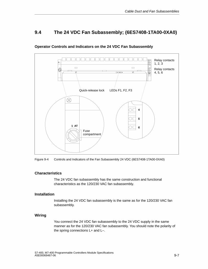
Cable Duct and Fan Subassemblies
9-7S7-400, M7-400 Programmable Controllers Module SpecificationsA5E00069467-06
9.4 The 24 VDC Fan Subassembly; (6ES7408-1TA00-0XA0)
Operator Controls and Indicators on the 24 VDC Fan Subassembly
LEDs F1, F2, F3Quick-release lock
Relay contacts 1, 2, 3
Relay contacts4, 5, 6
Fusecompartment
1 AT
1 AT
Figure 9-4 Controls and Indicators of the Fan Subassembly 24 VDC (6ES7408-1TA00-0XA0)
Characteristics
The 24 VDC fan subassembly has the same construction and functionalcharacteristics as the 120/230 VAC fan subassembly.
Installation
Installing the 24 VDC fan subassembly is the same as for the 120/230 VAC fansubassembly.
Wiring
You connect the 24 VDC fan subassembly to the 24 VDC supply in the samemanner as for the 120/230 VAC fan subassembly. You should note the polarity ofthe spring connections L+ and L–.
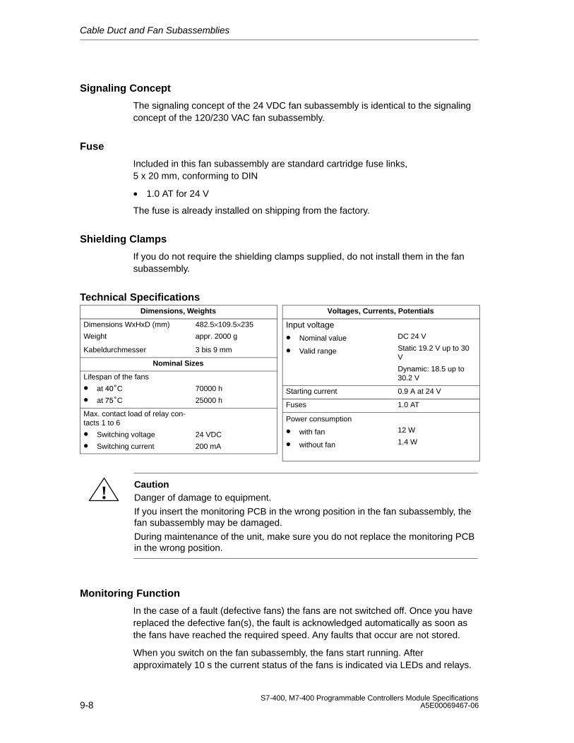
Cable Duct and Fan Subassemblies
9-8S7-400, M7-400 Programmable Controllers Module Specifications
A5E00069467-06
Signaling Concept
The signaling concept of the 24 VDC fan subassembly is identical to the signalingconcept of the 120/230 VAC fan subassembly.
Fuse
Included in this fan subassembly are standard cartridge fuse links, 5 x 20 mm, conforming to DIN
• 1.0 AT for 24 V
The fuse is already installed on shipping from the factory.
Shielding Clamps
If you do not require the shielding clamps supplied, do not install them in the fansubassembly.
Technical SpecificationsDimensions, Weights
Dimensions WxHxD (mm) 482.5×109.5×235
Weight appr. 2000 g
Kabeldurchmesser 3 bis 9 mm
Nominal Sizes
Lifespan of the fans
• at C
• at C
70000 h
25000 h
Max. contact load of relay con-tacts 1 to 6
• Switching voltage
• Switching current
24 VDC
200 mA
Voltages, Currents, Potentials
Input voltage
• Nominal value
• Valid range
DC 24 V
Static 19.2 V up to 30V
Dynamic: 18.5 up to30.2 V
Starting current 0.9 A at 24 V
Fuses 1.0 AT
Power consumption
• with fan
• without fan
12 W
1.4 W
!CautionDanger of damage to equipment.
If you insert the monitoring PCB in the wrong position in the fan subassembly, thefan subassembly may be damaged.
During maintenance of the unit, make sure you do not replace the monitoring PCBin the wrong position.
Monitoring Function
In the case of a fault (defective fans) the fans are not switched off. Once you havereplaced the defective fan(s), the fault is acknowledged automatically as soon asthe fans have reached the required speed. Any faults that occur are not stored.
When you switch on the fan subassembly, the fans start running. Afterapproximately 10 s the current status of the fans is indicated via LEDs and relays.
10-1S7-400, M7-400 Programmable Controllers Module SpecificationsA5E00069467-06
RS 485 Repeater
In this Chapter
In this chapter, you will find a detailed description of the RS 485 repeater.
Included in the description are:
• The purpose of the RS 485 repeater
• The maximum cable lengths possible between two RS 485 repeaters
• The functions of the individual operating elements and terminals
• Information about grounded and non-grounded operation
• Technical specifications and the block diagram
Further Information
You will find further information on the RS 485 repeater in the manuals Hardware and Installation in the Chapter “Configuring of an MPI or PROFIBUS DPnetwork”.
Chapter Overview
Section Description Page
10.1 Application and Characteristics;(6ES7972-0AA01-0XA0)
10-2
10.2 Appearance of the RS-485 Repeater; (6ES7972-0AA01-0XA0) 10-3
10.3 RS 485 Repeater in Ungrounded and Grounded Operation 10-4
10.4 Technical Specifications 10-6
10
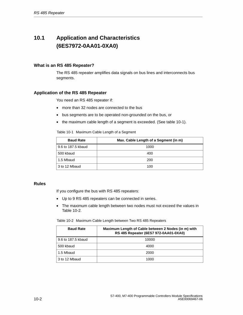
RS 485 Repeater
10-2S7-400, M7-400 Programmable Controllers Module Specifications
A5E00069467-06
10.1 Application and Characteristics(6ES7972-0AA01-0XA0)
What is an RS 485 Repeater?
The RS 485 repeater amplifies data signals on bus lines and interconnects bussegments.
Application of the RS 485 Repeater
You need an RS 485 repeater if:
• more than 32 nodes are connected to the bus
• bus segments are to be operated non-grounded on the bus, or
• the maximum cable length of a segment is exceeded. (See table 10-1).
Table 10-1 Maximum Cable Length of a Segment
Baud Rate Max. Cable Length of a Segment (in m)
9.6 to 187.5 kbaud 1000
500 kbaud 400
1.5 Mbaud 200
3 to 12 Mbaud 100
Rules
If you configure the bus with RS 485 repeaters:
• Up to 9 RS 485 repeaters can be connected in series.
• The maximum cable length between two nodes must not exceed the values inTable 10-2.
Table 10-2 Maximum Cable Length between Two RS 485 Repeaters
Baud Rate Maximum Length of Cable between 2 Nodes (in m) withRS 485 Repeater (6ES7 972-0AA01-0XA0)
9.6 to 187.5 kbaud 10000
500 kbaud 4000
1.5 Mbaud 2000
3 to 12 Mbaud 1000
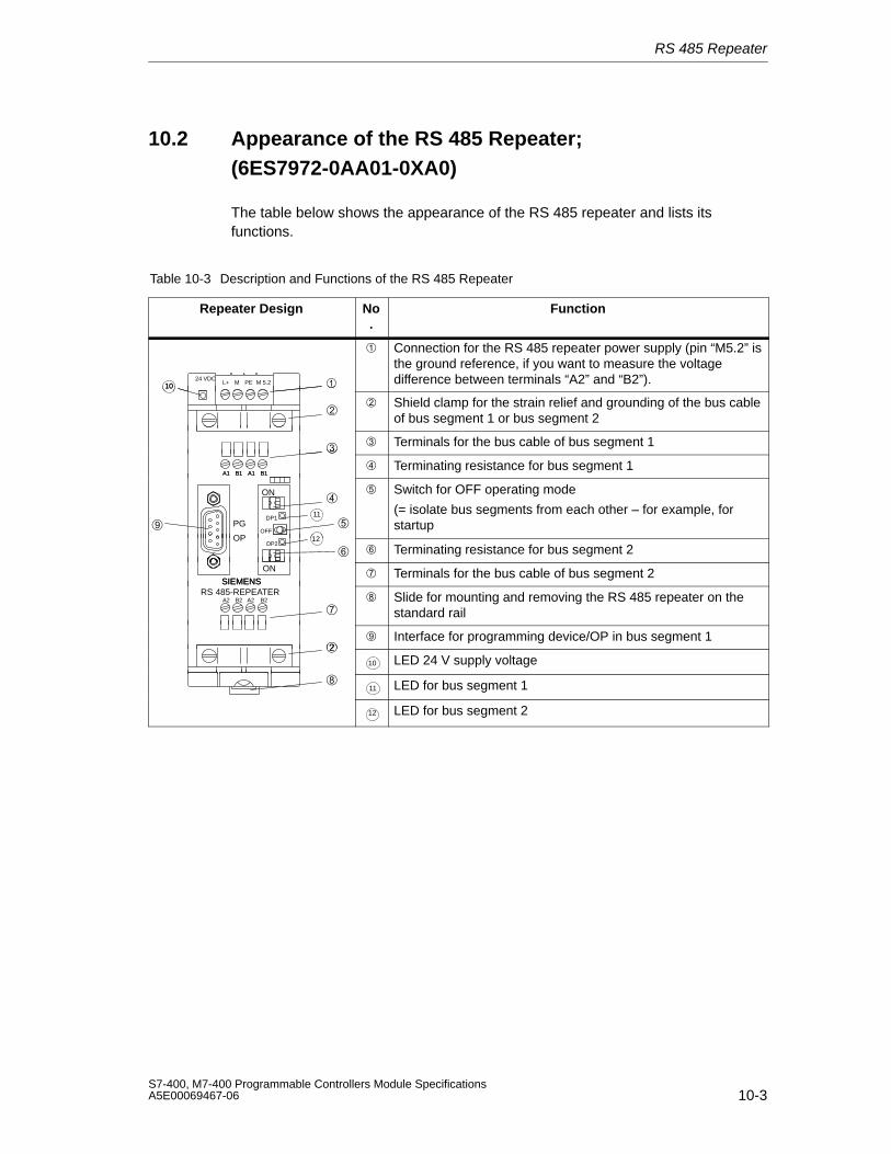
RS 485 Repeater
10-3S7-400, M7-400 Programmable Controllers Module SpecificationsA5E00069467-06
10.2 Appearance of the RS 485 Repeater;(6ES7972-0AA01-0XA0)
The table below shows the appearance of the RS 485 repeater and lists itsfunctions.
Table 10-3 Description and Functions of the RS 485 Repeater
Repeater Design No.
Function
24 VDCL+ M PE M 5.2 10
Connection for the RS 485 repeater power supply (pin “M5.2” isthe ground reference, if you want to measure the voltagedifference between terminals “A2” and “B2”).
10
Shield clamp for the strain relief and grounding of the bus cableof bus segment 1 or bus segment 2
Terminals for the bus cable of bus segment 1
A1 B1 A1 B1 Terminating resistance for bus segment 1
A1 B1 A1 B1
PG11
OFF
ON
DP1
Switch for OFF operating mode
(= isolate bus segments from each other – for example, forstartup
OPDP2
12
Terminating resistance for bus segment 2
SIEMENS
ON Terminals for the bus cable of bus segment 2
SIEMENSRS 485-REPEATER
A2 B2 A2 B2 Slide for mounting and removing the RS 485 repeater on the
standard rail
Interface for programming device/OP in bus segment 1
10 LED 24 V supply voltage
11 LED for bus segment 1
12 LED for bus segment 2
RS 485 Repeater
10-4S7-400, M7-400 Programmable Controllers Module Specifications
A5E00069467-06
10.3 RS 485 Repeater in Ungrounded and GroundedOperation
Grounded or Ungrounded
The RS 485 repeater is ...
• grounded, if all other nodes in the segment are also operated with a groundedpotential
• ungrounded, if all other nodes in the segment are operated with an ungroundedpotential
Note
The bus segment 1 is grounded if you connect a programming device to thePG/OP socket of the RS 485 repeater. Ground connection is effected since theMPI in the programming device is grounded and the PG/OP socket is connectedinternally with bus segment 1 in the RS 485 repeater.
Grounded Operation of the RS 485 Repeater
For grounded operation of the RS 485 repeater, you must jump terminals “M” and“PE” on the top of the RS 485 repeater.
Ungrounded Operation of the RS 485 Repeater
For ungrounded operation of the RS 485 repeater, “M” and “PE” on the top of theRS 485 repeater must not be interconnected. In addition, the supply voltage of theRS 485 repeater must be ungrounded.
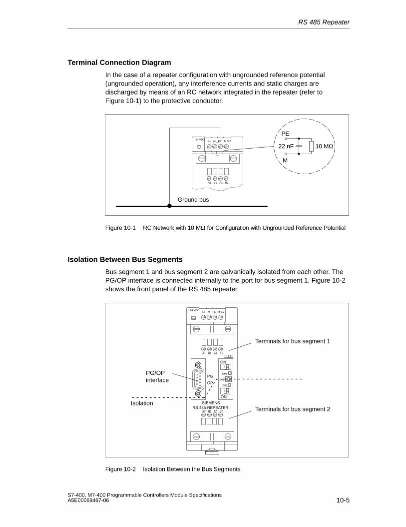
RS 485 Repeater
10-5S7-400, M7-400 Programmable Controllers Module SpecificationsA5E00069467-06
Terminal Connection Diagram
In the case of a repeater configuration with ungrounded reference potential(ungrounded operation), any interference currents and static charges aredischarged by means of an RC network integrated in the repeater (refer toFigure 10-1) to the protective conductor.
24 VDCL+ M PE M 5.2
A1 B1 A1 B1
M
22 nF 10 MΩ
Ground bus
PE
Figure 10-1 RC Network with 10 MΩ for Configuration with Ungrounded Reference Potential
Isolation Between Bus Segments
Bus segment 1 and bus segment 2 are galvanically isolated from each other. ThePG/OP interface is connected internally to the port for bus segment 1. Figure 10-2shows the front panel of the RS 485 repeater.
24 VDCL+ M PE M 5.2
SIEMENSRS 485-REPEATER
ON
A1 B1 A1 B1
A2 B2 A2 B2
PG
OPDP2
OFF
ON
DP1
Terminals for bus segment 1
Terminals for bus segment 2
PG/OPinterface
Isolation
Figure 10-2 Isolation Between the Bus Segments
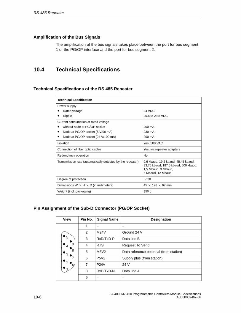
RS 485 Repeater
10-6S7-400, M7-400 Programmable Controllers Module Specifications
A5E00069467-06
Amplification of the Bus Signals
The amplification of the bus signals takes place between the port for bus segment1 or the PG/OP interface and the port for bus segment 2.
10.4 Technical Specifications
Technical Specifications of the RS 485 Repeater
Technical Specification
Power supply
• Rated voltage 24 VDC
• Ripple 20.4 to 28.8 VDC
Current consumption at rated voltage
• without node at PG/OP socket 200 mA
• Node at PG/OP socket (5 V/90 mA) 230 mA
• Node at PG/OP socket (24 V/100 mA) 200 mA
Isolation Yes, 500 VAC
Connection of fiber optic cables Yes, via repeater adapters
Redundancy operation No
Transmission rate (automatically detected by the repeater) 9.6 kbaud, 19.2 kbaud, 45.45 kbaud,93.75 kbaud, 187.5 kbaud, 500 kbaud.1,5 Mbaud. 3 Mbaud,6 Mbaud, 12 Mbaud
Degree of protection IP 20
Dimensions W H D (in millimeters) 45 128 67 mm
Weight (incl. packaging) 350 g
Pin Assignment of the Sub-D Connector (PG/OP Socket)
View Pin No. Signal Name Designation
1 – –
2 M24V Ground 24 V5 3 RxD/TxD-P Data line B
94 4 RTS Request To Send
8 5 M5V2 Data reference potential (from station)3
7 6 P5V2 Supply plus (from station)2
6 7 P24V 24 V1 8 RxD/TxD-N Data line A
9 – –
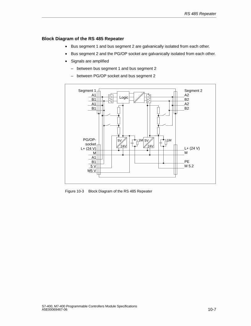
RS 485 Repeater
10-7S7-400, M7-400 Programmable Controllers Module SpecificationsA5E00069467-06
Block Diagram of the RS 485 Repeater
• Bus segment 1 and bus segment 2 are galvanically isolated from each other.
• Bus segment 2 and the PG/OP socket are galvanically isolated from each other.
• Signals are amplified
– between bus segment 1 and bus segment 2
– between PG/OP socket and bus segment 2
5V
24V
Segment 2A2B2A2B2
Segment 1A1B1A1B1
PG/OP-socket
L+ (24 V)M
A1B15 V
M5 V
L+ (24 V)M
PEM 5.2
Logic
5V
24V
1M1M
Figure 10-3 Block Diagram of the RS 485 Repeater

RS 485 Repeater
10-8S7-400, M7-400 Programmable Controllers Module Specifications
A5E00069467-06
11-1S7-400, M7-400 Programmable Controllers Module SpecificationsA5E00069467-06
CPUs for M7-400
In this Chapter
This chapter describes the CPUs of the M7-400 automation computer:
• CPU 486-3,
• CPU 488-3,
The CPUs differ essentially in their clock frequencies. You will find a comparison oftheir performance features in Table 11-1.
The tables in Sections 11.1 and 11.2 give an overview of the performance featuresand technical specifications of the CPUs.
Following this overview, the modules are described in detail.
Chapter Overview
Section Description Page
11.1 Performance Features 11-2
11.2 Technical Specifications 11-3
11.3 Function Elements 11-4
11.4 The BIOS Setup 11-16
11.5 I/O Addresses, Main Memory and Interrupt Assignments 11-40
11
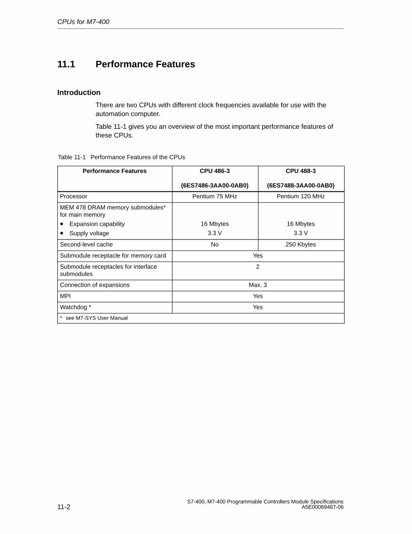
CPUs for M7-400
11-2S7-400, M7-400 Programmable Controllers Module Specifications
A5E00069467-06
11.1 Performance Features
Introduction
There are two CPUs with different clock frequencies available for use with theautomation computer.
Table 11-1 gives you an overview of the most important performance features ofthese CPUs.
Table 11-1 Performance Features of the CPUs
Performance Features CPU 486-3
(6ES7486-3AA00-0AB0)
CPU 488-3
(6ES7488-3AA00-0AB0)
Processor Pentium 75 MHz Pentium 120 MHz
MEM 478 DRAM memory submodules*for main memory
• Expansion capability
• Supply voltage
16 Mbytes
3.3 V
16 Mbytes
3.3 V
Second-level cache No 250 Kbytes
Submodule receptacle for memory card Yes
Submodule receptacles for interfacesubmodules
2
Connection of expansions Max. 3
MPI Yes
Watchdog * Yes
* see M7-SYS User Manual
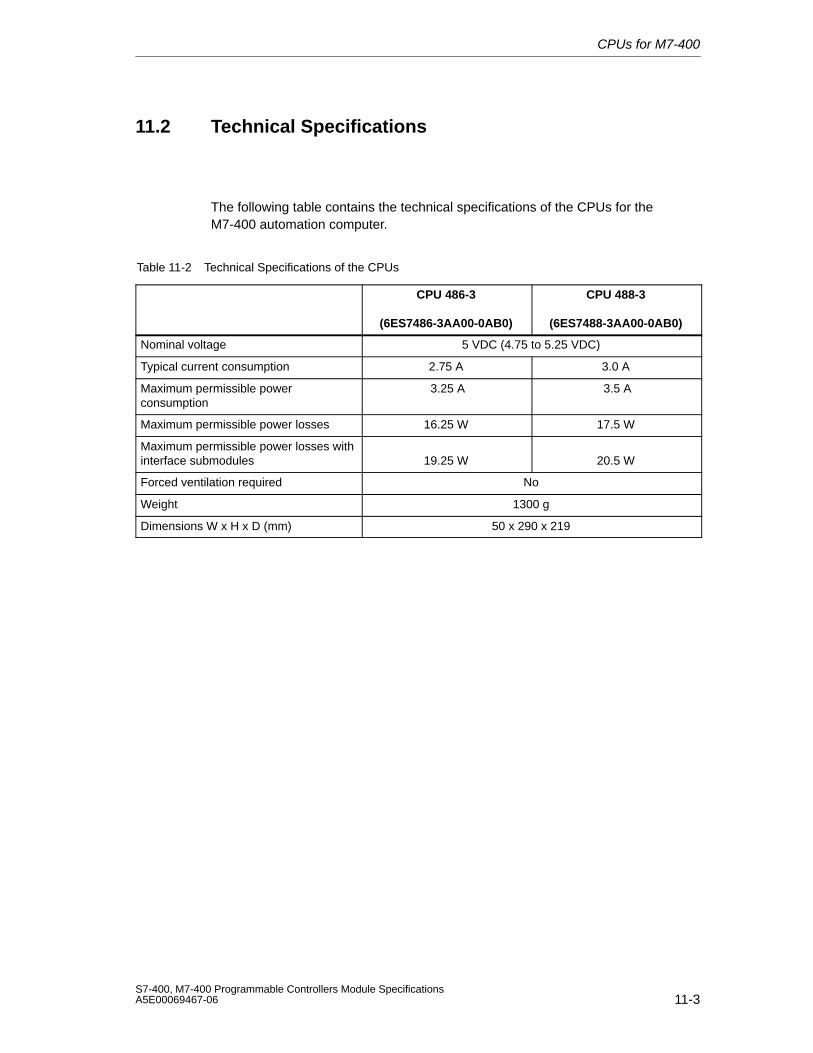
CPUs for M7-400
11-3S7-400, M7-400 Programmable Controllers Module SpecificationsA5E00069467-06
11.2 Technical Specifications
The following table contains the technical specifications of the CPUs for theM7-400 automation computer.
Table 11-2 Technical Specifications of the CPUs
CPU 486-3
(6ES7486-3AA00-0AB0)
CPU 488-3
(6ES7488-3AA00-0AB0)
Nominal voltage 5 VDC (4.75 to 5.25 VDC)
Typical current consumption 2.75 A 3.0 A
Maximum permissible powerconsumption
3.25 A 3.5 A
Maximum permissible power losses 16.25 W 17.5 W
Maximum permissible power losses withinterface submodules 19.25 W 20.5 W
Forced ventilation required No
Weight 1300 g
Dimensions W x H x D (mm) 50 x 290 x 219
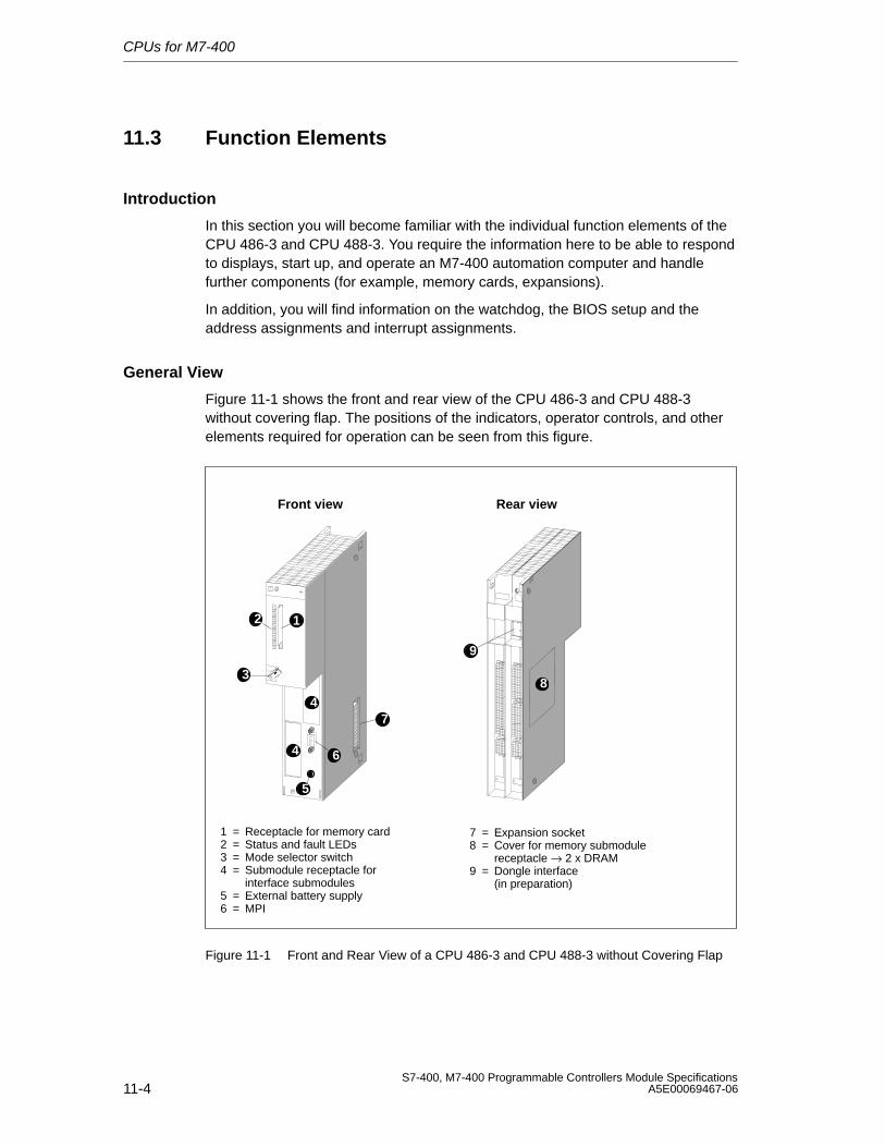
CPUs for M7-400
11-4S7-400, M7-400 Programmable Controllers Module Specifications
A5E00069467-06
11.3 Function Elements
Introduction
In this section you will become familiar with the individual function elements of theCPU 486-3 and CPU 488-3. You require the information here to be able to respondto displays, start up, and operate an M7-400 automation computer and handlefurther components (for example, memory cards, expansions).
In addition, you will find information on the watchdog, the BIOS setup and theaddress assignments and interrupt assignments.
General View
Figure 11-1 shows the front and rear view of the CPU 486-3 and CPU 488-3without covering flap. The positions of the indicators, operator controls, and otherelements required for operation can be seen from this figure.
Front view Rear view
1 = Receptacle for memory card2 = Status and fault LEDs3 = Mode selector switch4 = Submodule receptacle for
interface submodules5 = External battery supply6 = MPI
7 = Expansion socket8 = Cover for memory submodule
receptacle → 2 x DRAM9 = Dongle interface
(in preparation)
12
3
4
4 6
5
7
8
9
Figure 11-1 Front and Rear View of a CPU 486-3 and CPU 488-3 without Covering Flap
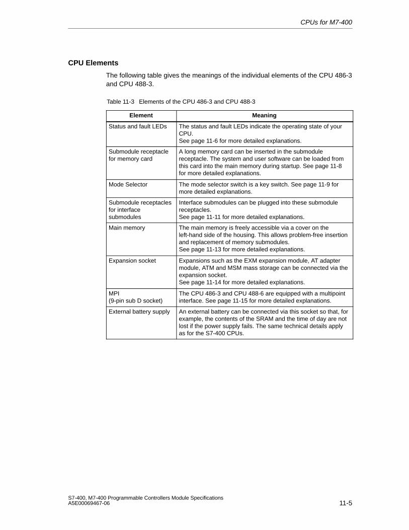
CPUs for M7-400
11-5S7-400, M7-400 Programmable Controllers Module SpecificationsA5E00069467-06
CPU Elements
The following table gives the meanings of the individual elements of the CPU 486-3and CPU 488-3.
Table 11-3 Elements of the CPU 486-3 and CPU 488-3
Element Meaning
Status and fault LEDs The status and fault LEDs indicate the operating state of yourCPU. See page 11-6 for more detailed explanations.
Submodule receptaclefor memory card
A long memory card can be inserted in the submodulereceptacle. The system and user software can be loaded fromthis card into the main memory during startup. See page 11-8for more detailed explanations.
Mode Selector The mode selector switch is a key switch. See page 11-9 formore detailed explanations.
Submodule receptaclesfor interfacesubmodules
Interface submodules can be plugged into these submodulereceptacles. See page 11-11 for more detailed explanations.
Main memory The main memory is freely accessible via a cover on theleft-hand side of the housing. This allows problem-free insertionand replacement of memory submodules.See page 11-13 for more detailed explanations.
Expansion socket Expansions such as the EXM expansion module, AT adaptermodule, ATM and MSM mass storage can be connected via theexpansion socket. See page 11-14 for more detailed explanations.
MPI(9-pin sub D socket)
The CPU 486-3 and CPU 488-6 are equipped with a multipointinterface. See page 11-15 for more detailed explanations.
External battery supply An external battery can be connected via this socket so that, forexample, the contents of the SRAM and the time of day are notlost if the power supply fails. The same technical details applyas for the S7-400 CPUs.
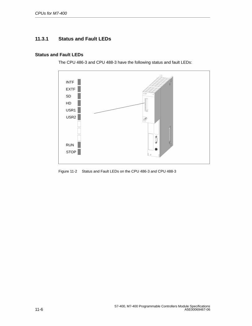
CPUs for M7-400
11-6S7-400, M7-400 Programmable Controllers Module Specifications
A5E00069467-06
11.3.1 Status and Fault LEDs
Status and Fault LEDs
The CPU 486-3 and CPU 488-3 have the following status and fault LEDs:
INTF
EXTF
SD
HD
USR1
USR2
RUN
STOP
Figure 11-2 Status and Fault LEDs on the CPU 486-3 and CPU 488-3
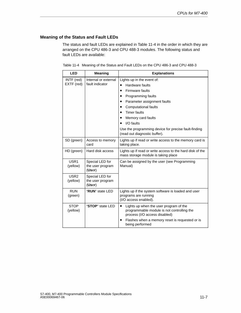
CPUs for M7-400
11-7S7-400, M7-400 Programmable Controllers Module SpecificationsA5E00069467-06
Meaning of the Status and Fault LEDs
The status and fault LEDs are explained in Table 11-4 in the order in which they arearranged on the CPU 486-3 and CPU 488-3 modules. The following status andfault LEDs are available:
Table 11-4 Meaning of the Status and Fault LEDs on the CPU 486-3 and CPU 488-3
LED Meaning Explanations
INTF (red)EXTF (red)
Internal or externalfault indicator
Lights up in the event of:
• Hardware faults
• Firmware faults
• Programming faults
• Parameter assignment faults
• Computational faults
• Timer faults
• Memory card faults
• I/O faults
Use the programming device for precise fault-finding(read out diagnostic buffer).
SD (green) Access to memorycard
Lights up if read or write access to the memory card istaking place.
HD (green) Hard disk access Lights up if read or write access to the hard disk of themass storage module is taking place
USR1(yellow)
Special LED forthe user program(User)
Can be assigned by the user (see ProgrammingManual)
USR2(yellow)
Special LED forthe user program(User)
RUN(green)
“RUN” state LED Lights up if the system software is loaded and userprograms are running (I/O access enabled).
STOP(yellow)
“STOP” state LED • Lights up when the user program of theprogrammable module is not controlling theprocess (I/O access disabled)
• Flashes when a memory reset is requested or isbeing performed
CPUs for M7-400
11-8S7-400, M7-400 Programmable Controllers Module Specifications
A5E00069467-06
11.3.2 Memory Cards
Introduction
The CPU 486-3 and CPU 488-3 offer the possibility of operating a memory card inthe same way as a diskette. In this section, you will learn how you can use theseoptions.
NoteIf the power fails during a write access to the memory card, the entire contents ofthe memory card can be damaged under unfavorable conditions.
Please note that in contrast to a diskette, a memory card is only designed for alimited number of write accesses.
Memory Card
A memory card emulates a diskette from which an operating system can also bebooted. In addition, a memory card can also be used to exchange user softwareand user data.
Memory cards with Flash EPROM are available for the CPUs (see the orderingdata).
Drive Assignment
The memory card is accessed by the operating system in the same way as aconventional drive.
You can set the drive assignment in the BIOS setup (Section 11.4.11, page 11-35).
Boot Sequence
You can set the boot sequence in the BIOS setup (Section 11.4.12, page 11-36).
Formatting
Memory cards are formatted with the program FTLFORM.EXE included with thesystem software. Read the relevant sections in the M7-SYS User Manual.
NoteThe memory capacity specified for the memory card is the actual physical memorycapacity (gross). Formatting reduces the gross memory capacity to approximately80% (net) that is then available to the operating system for storing data/programs.
UNDELETE: Files which were deleted from the memory card cannot be restoredusing UNDELETE programs.
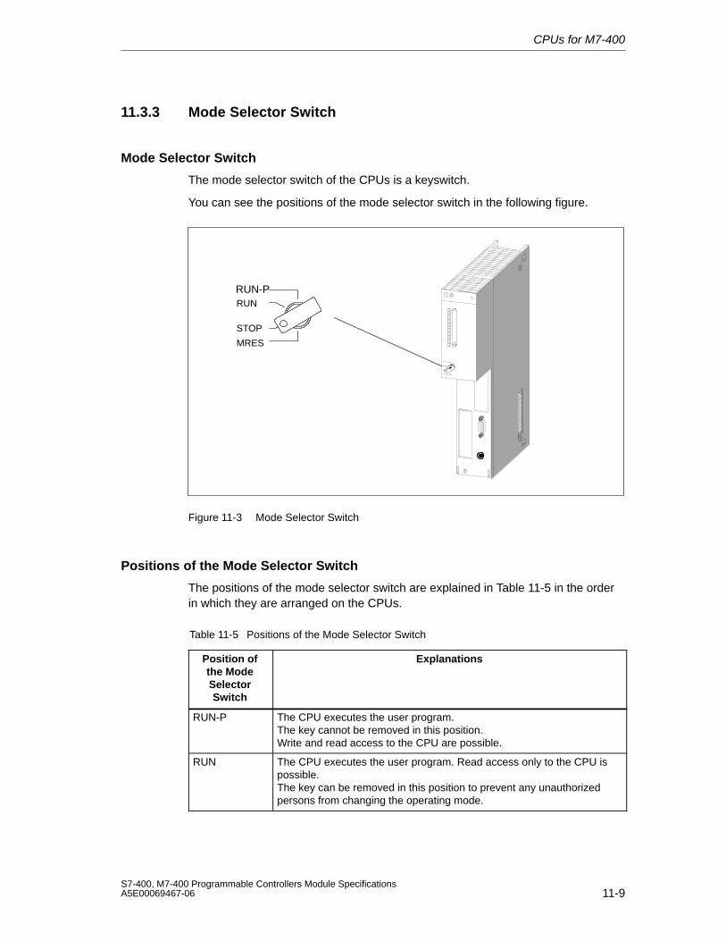
CPUs for M7-400
11-9S7-400, M7-400 Programmable Controllers Module SpecificationsA5E00069467-06
11.3.3 Mode Selector Switch
Mode Selector Switch
The mode selector switch of the CPUs is a keyswitch.
You can see the positions of the mode selector switch in the following figure.
MRES
STOP
RUN
RUN-P
Figure 11-3 Mode Selector Switch
Positions of the Mode Selector Switch
The positions of the mode selector switch are explained in Table 11-5 in the orderin which they are arranged on the CPUs.
Table 11-5 Positions of the Mode Selector Switch
Position ofthe ModeSelectorSwitch
Explanations
RUN-P The CPU executes the user program.The key cannot be removed in this position.Write and read access to the CPU are possible.
RUN The CPU executes the user program. Read access only to the CPU ispossible.The key can be removed in this position to prevent any unauthorizedpersons from changing the operating mode.
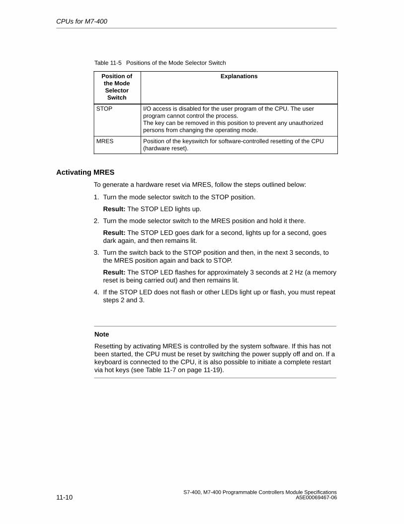
CPUs for M7-400
11-10S7-400, M7-400 Programmable Controllers Module Specifications
A5E00069467-06
Table 11-5 Positions of the Mode Selector Switch
Position ofthe ModeSelectorSwitch
Explanations
STOP I/O access is disabled for the user program of the CPU. The userprogram cannot control the process.The key can be removed in this position to prevent any unauthorizedpersons from changing the operating mode.
MRES Position of the keyswitch for software-controlled resetting of the CPU(hardware reset).
Activating MRES
To generate a hardware reset via MRES, follow the steps outlined below:
1. Turn the mode selector switch to the STOP position.
Result: The STOP LED lights up.
2. Turn the mode selector switch to the MRES position and hold it there.
Result: The STOP LED goes dark for a second, lights up for a second, goesdark again, and then remains lit.
3. Turn the switch back to the STOP position and then, in the next 3 seconds, tothe MRES position again and back to STOP.
Result: The STOP LED flashes for approximately 3 seconds at 2 Hz (a memoryreset is being carried out) and then remains lit.
4. If the STOP LED does not flash or other LEDs light up or flash, you must repeatsteps 2 and 3.
Note
Resetting by activating MRES is controlled by the system software. If this has notbeen started, the CPU must be reset by switching the power supply off and on. If akeyboard is connected to the CPU, it is also possible to initiate a complete restartvia hot keys (see Table 11-7 on page 11-19).
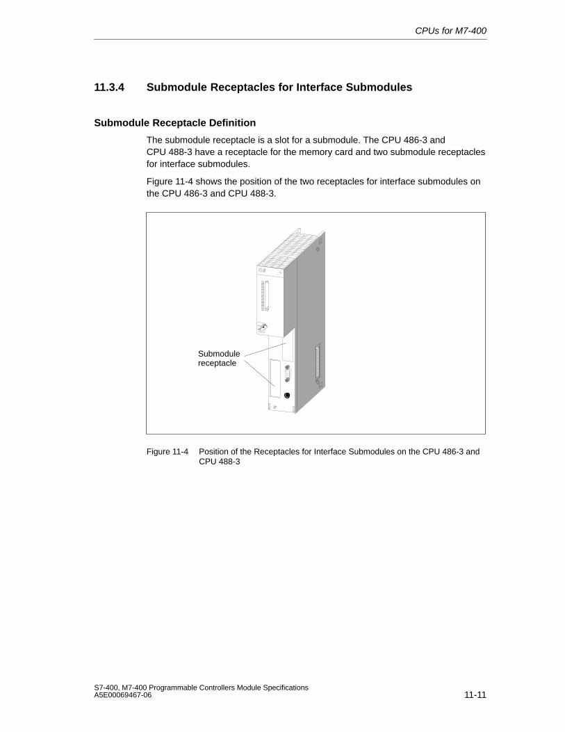
CPUs for M7-400
11-11S7-400, M7-400 Programmable Controllers Module SpecificationsA5E00069467-06
11.3.4 Submodule Receptacles for Interface Submodules
Submodule Receptacle Definition
The submodule receptacle is a slot for a submodule. The CPU 486-3 andCPU 488-3 have a receptacle for the memory card and two submodule receptaclesfor interface submodules.
Figure 11-4 shows the position of the two receptacles for interface submodules onthe CPU 486-3 and CPU 488-3.
Submodulereceptacle
Figure 11-4 Position of the Receptacles for Interface Submodules on the CPU 486-3 andCPU 488-3
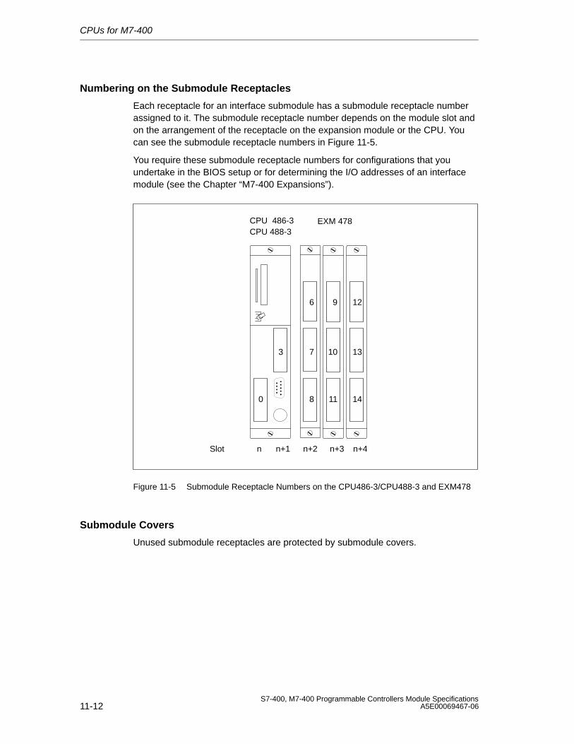
CPUs for M7-400
11-12S7-400, M7-400 Programmable Controllers Module Specifications
A5E00069467-06
Numbering on the Submodule Receptacles
Each receptacle for an interface submodule has a submodule receptacle numberassigned to it. The submodule receptacle number depends on the module slot andon the arrangement of the receptacle on the expansion module or the CPU. Youcan see the submodule receptacle numbers in Figure 11-5.
You require these submodule receptacle numbers for configurations that youundertake in the BIOS setup or for determining the I/O addresses of an interfacemodule (see the Chapter “M7-400 Expansions”).
3
0 8
6
7
9 12
10 13
11 14
CPU 486-3CPU 488-3
EXM 478
Slot n n+2 n+3 n+4n+1
Figure 11-5 Submodule Receptacle Numbers on the CPU486-3/CPU488-3 and EXM478
Submodule Covers
Unused submodule receptacles are protected by submodule covers.
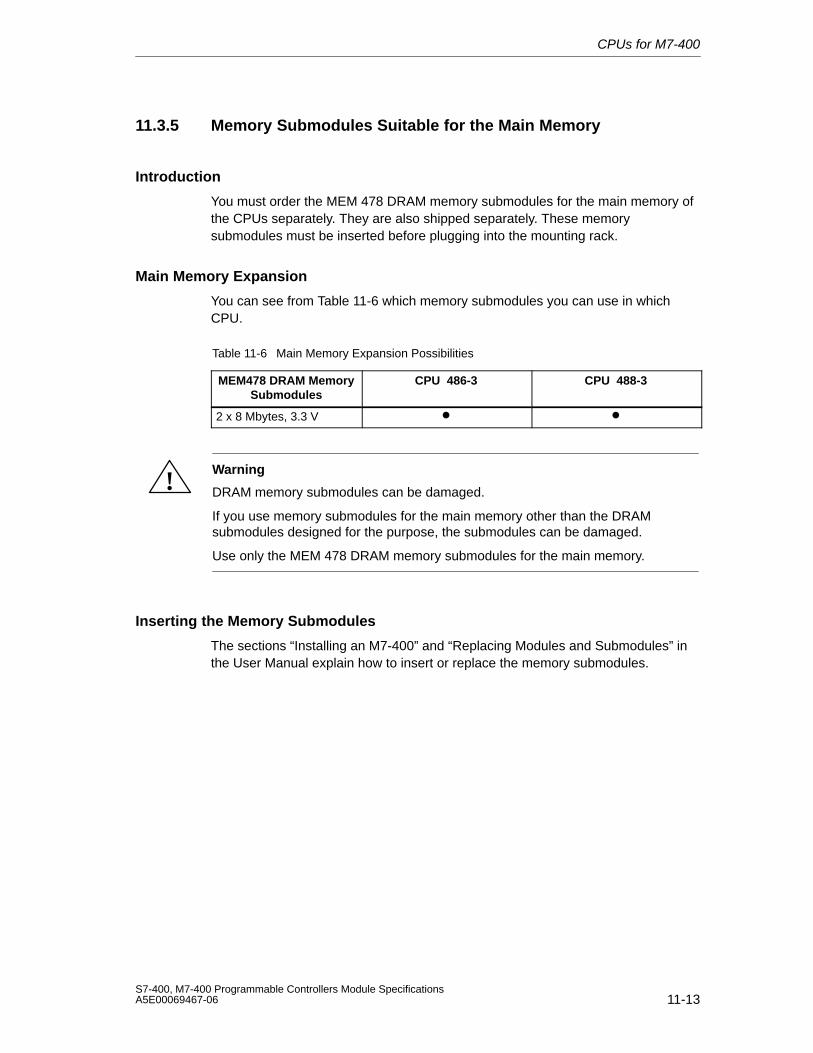
CPUs for M7-400
11-13S7-400, M7-400 Programmable Controllers Module SpecificationsA5E00069467-06
11.3.5 Memory Submodules Suitable for the Main Memory
Introduction
You must order the MEM 478 DRAM memory submodules for the main memory ofthe CPUs separately. They are also shipped separately. These memorysubmodules must be inserted before plugging into the mounting rack.
Main Memory Expansion
You can see from Table 11-6 which memory submodules you can use in whichCPU.
Table 11-6 Main Memory Expansion Possibilities
MEM478 DRAM MemorySubmodules
CPU 486-3 CPU 488-3
2 x 8 Mbytes, 3.3 V • •
!Warning
DRAM memory submodules can be damaged.
If you use memory submodules for the main memory other than the DRAMsubmodules designed for the purpose, the submodules can be damaged.
Use only the MEM 478 DRAM memory submodules for the main memory.
Inserting the Memory Submodules
The sections “Installing an M7-400” and “Replacing Modules and Submodules” inthe User Manual explain how to insert or replace the memory submodules.
CPUs for M7-400
11-14S7-400, M7-400 Programmable Controllers Module Specifications
A5E00069467-06
11.3.6 Expansion Socket
Introduction
The CPU 486-3 and CPU 488-3 are each equipped with an expansion socket. TheISA bus is continued via the expansion socket.
Which Expansions Can Be Connected?
One EXM 478 extension module with up to three interface submodules, oneMSM 478 mass storage module with diskette and hard disk drives, or one ATM 478AT adapter module for short AT cards can be connected direct to the CPUs.
A total of up to three expansions can be connected in series to the CPU.
If three EXM 478 expansion modules are connected, up to 11 interfacesubmodules can be operated together with the slots on each CPU (seeSection 11.3.4).
CPUs for M7-400
11-15S7-400, M7-400 Programmable Controllers Module SpecificationsA5E00069467-06
11.3.7 Multipoint Interface (MPI)
X1 Interface
The X1 interface of the CPU 486-3 and CPU 488-3 for connecting devices such asPCs/programming devices is a multipoint interface (MPI) and is connected via a9-pin sub D connector.
Suitable Devices
You can connect the following at the MPI:
• Programming devices (PGs/PCs)
• Operator panels (OPs)
• Additional CPUs.
You can address up to 127 communications partners (programming devices, OPs,CPUs) via the multipoint interface of the CPU 486-3 and CPU 488-3. A maximumof 44 connections can be made to the CPU.
Connectors
Use only bus connectors or PG cables for connecting devices to the MPI (seeChapter 6).
CPUs for M7-400
11-16S7-400, M7-400 Programmable Controllers Module Specifications
A5E00069467-06
11.4 The BIOS Setup
Overview
The BIOS setup handles the configuration of the relevant CPUs in your M7-400system. The settings and technical information concerning the configuration of thisprogrammable module are displayed in the BIOS setup. The CPUs already have adefault setup. It is set in such a way that the minimal configuration of a CPU (withmemory card drive) will power up via BIOS setup without programming.
You can change the default settings in the BIOS setup. This becomes necessary if,for example, you want to connect expansions to your CPU (expansion module withinterface submodules, mass storage module with diskette and hard disk drives, orAT adapter module with short AT card). You must inform the operating system ofthese expansions.
If you want to make settings in the BIOS setup, you can do so:
• Directly at the relevant module if your M7-400 is equipped with interfacesubmodules and I/O devices such as a monitor and keyboard (interfacesubmodule IF 962-VGA).
• Remote setup with a terminal program (for example, HyperTerminal underWindows 95) on programming device/PC or with an ANSI terminal via theCOM1 port (interface submodule IF 962-COM).
Remote Setup
To run BIOS settings via the Remote Setup without the interface submoduleIF 962-VGA, follow the steps outlined below:
1. Switch off the line voltage to your M7-400.
2. Connect the programming device to the COM1 port of the SIMATIC M7 device(see Section 8.7.2 of the Installation Manual).
3. On your programming device under Windows 95 select “Start > Accessories >Hyperterminal”.
4. In the HyperTerminal window, select the menu command “File > NewConnection”. Enter a connection description and select the COM port with thefollowing transmission properties: 19000 bps, 8 data bits, no parity, 1 stop bit,no flow control.
5. Switch on the line voltage to the M7-400 and hold the “Q” key pressed duringstartup until the M7-400 registers itself in the HyperTerminal with the hardwaretests (a “U” appears).
6. Press the ESC button immediately.
Result: You are in the BIOS setup.
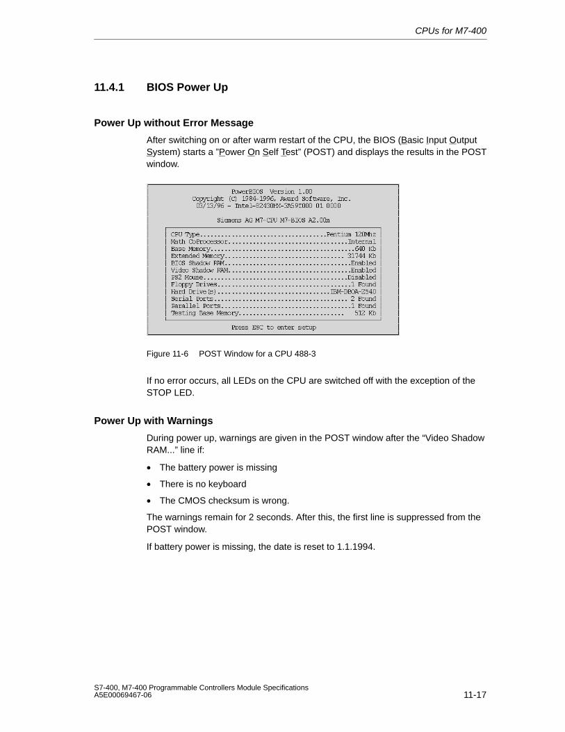
CPUs for M7-400
11-17S7-400, M7-400 Programmable Controllers Module SpecificationsA5E00069467-06
11.4.1 BIOS Power Up
Power Up without Error Message
After switching on or after warm restart of the CPU, the BIOS (Basic Input OutputSystem) starts a ”Power On Self Test” (POST) and displays the results in the POSTwindow.
Figure 11-6 POST Window for a CPU 488-3
If no error occurs, all LEDs on the CPU are switched off with the exception of theSTOP LED.
Power Up with Warnings
During power up, warnings are given in the POST window after the “Video ShadowRAM...” line if:
• The battery power is missing
• There is no keyboard
• The CMOS checksum is wrong.
The warnings remain for 2 seconds. After this, the first line is suppressed from thePOST window.
If battery power is missing, the date is reset to 1.1.1994.
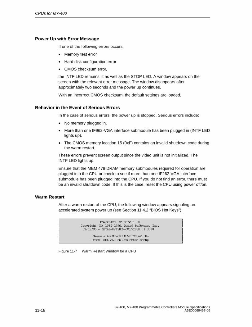
CPUs for M7-400
11-18S7-400, M7-400 Programmable Controllers Module Specifications
A5E00069467-06
Power Up with Error Message
If one of the following errors occurs:
• Memory test error
• Hard disk configuration error
• CMOS checksum error,
the INTF LED remains lit as well as the STOP LED. A window appears on thescreen with the relevant error message. The window disappears afterapproximately two seconds and the power up continues.
With an incorrect CMOS checksum, the default settings are loaded.
Behavior in the Event of Serious Errors
In the case of serious errors, the power up is stopped. Serious errors include:
• No memory plugged in.
• More than one IF962-VGA interface submodule has been plugged in (INTF LEDlights up).
• The CMOS memory location 15 (0xF) contains an invalid shutdown code duringthe warm restart.
These errors prevent screen output since the video unit is not initialized. TheINTF LED lights up.
Ensure that the MEM 478 DRAM memory submodules required for operation areplugged into the CPU or check to see if more than one IF262-VGA interfacesubmodule has been plugged into the CPU. If you do not find an error, there mustbe an invalid shutdown code. If this is the case, reset the CPU using power off/on.
Warm Restart
After a warm restart of the CPU, the following window appears signaling anaccelerated system power up (see Section 11.4.2 “BIOS Hot Keys”).
Figure 11-7 Warm Restart Window for a CPU
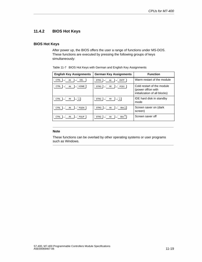
CPUs for M7-400
11-19S7-400, M7-400 Programmable Controllers Module SpecificationsA5E00069467-06
11.4.2 BIOS Hot Keys
BIOS Hot Keys
After power up, the BIOS offers the user a range of functions under MS-DOS.These functions are executed by pressing the following groups of keyssimultaneously:
Table 11-7 BIOS Hot Keys with German and English Key Assignments
English Key Assignments German Key Assignments Function
Warm restart of the module
Cold restart of the module(power off/on withinitialization of all blocks)
↓ ↓ IDE hard disk in standbymode
!" ↓ Screen saver on (darkscreen)
# !" ↑ Screen saver off
Note
These functions can be overlaid by other operating systems or user programssuch as Windows.
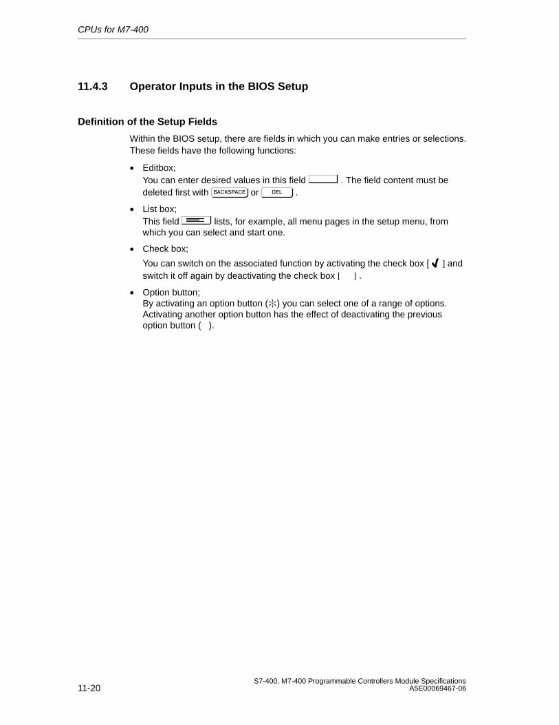
CPUs for M7-400
11-20S7-400, M7-400 Programmable Controllers Module Specifications
A5E00069467-06
11.4.3 Operator Inputs in the BIOS Setup
Definition of the Setup Fields
Within the BIOS setup, there are fields in which you can make entries or selections.These fields have the following functions:
• Editbox;You can enter desired values in this field . The field content must bedeleted first with $ or .
• List box;This field lists, for example, all menu pages in the setup menu, fromwhich you can select and start one.
• Check box;
You can switch on the associated function by activating the check box [ ] andswitch it off again by deactivating the check box [ ] .
• Option button;By activating an option button () you can select one of a range of options.Activating another option button has the effect of deactivating the previousoption button ( ).
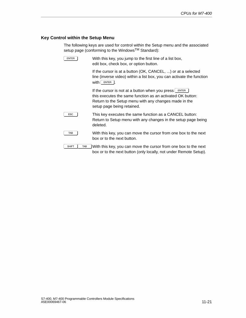
CPUs for M7-400
11-21S7-400, M7-400 Programmable Controllers Module SpecificationsA5E00069467-06
Key Control within the Setup Menu
The following keys are used for control within the Setup menu and the associatedsetup page (conforming to the WindowsTM Standard):
With this key, you jump to the first line of a list box,edit box, check box, or option button.
If the cursor is at a button (OK, CANCEL, ...) or at a selected line (inverse video) within a list box, you can activate the function with .
If the cursor is not at a button when you press this executes the same function as an activated OK button:Return to the Setup menu with any changes made in the setup page being retained.
This key executes the same function as a CANCEL button: Return to Setup menu with any changes in the setup page beingdeleted.
With this key, you can move the cursor from one box to the next box or to the next button.
With this key, you can move the cursor from one box to the nextbox or to the next button (only locally, not under Remote Setup).
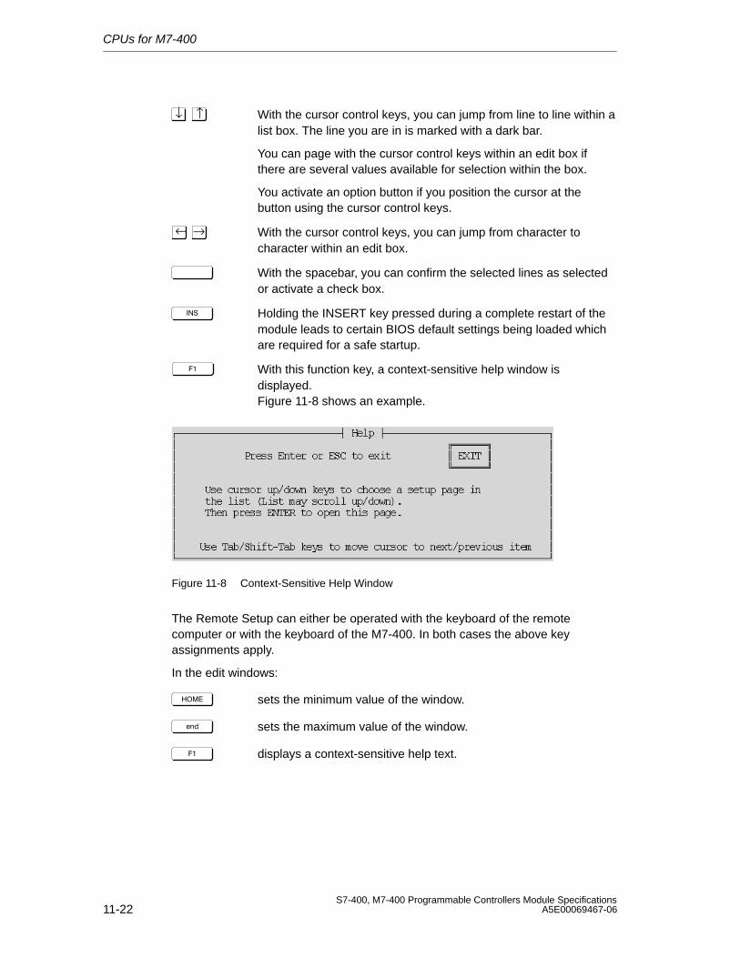
CPUs for M7-400
11-22S7-400, M7-400 Programmable Controllers Module Specifications
A5E00069467-06
↑↓ With the cursor control keys, you can jump from line to line within alist box. The line you are in is marked with a dark bar.
You can page with the cursor control keys within an edit box if there are several values available for selection within the box.
You activate an option button if you position the cursor at the button using the cursor control keys.
→← With the cursor control keys, you can jump from character to character within an edit box.
With the spacebar, you can confirm the selected lines as selected or activate a check box.
Holding the INSERT key pressed during a complete restart of the module leads to certain BIOS default settings being loaded which are required for a safe startup.
With this function key, a context-sensitive help window is displayed. Figure 11-8 shows an example.
Figure 11-8 Context-Sensitive Help Window
The Remote Setup can either be operated with the keyboard of the remotecomputer or with the keyboard of the M7-400. In both cases the above keyassignments apply.
In the edit windows:
sets the minimum value of the window.
%&" sets the maximum value of the window.
displays a context-sensitive help text.
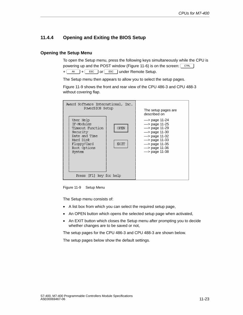
CPUs for M7-400
11-23S7-400, M7-400 Programmable Controllers Module SpecificationsA5E00069467-06
11.4.4 Opening and Exiting the BIOS Setup
Opening the Setup Menu
To open the Setup menu, press the following keys simultaneously while the CPU ispowering up and the POST window (Figure 11-6) is on the screen:
+ + or under Remote Setup.
The Setup menu then appears to allow you to select the setup pages.
Figure 11-9 shows the front and rear view of the CPU 486-3 and CPU 488-3without covering flap.
––> page 11-24––> page 11-25––> page 11-29––> page 11-30––> page 11-32––> page 11-33––> page 11-35––> page 11-36––> page 11-38
The setup pages are described on
Figure 11-9 Setup Menu
The Setup menu consists of:
• A list box from which you can select the required setup page,
• An OPEN button which opens the selected setup page when activated,
• An EXIT button which closes the Setup menu after prompting you to decidewhether changes are to be saved or not,
The setup pages for the CPU 486-3 and CPU 488-3 are shown below.
The setup pages below show the default settings.
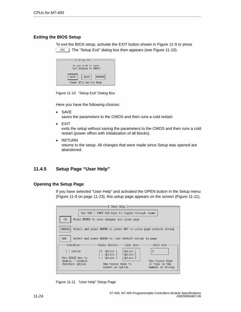
CPUs for M7-400
11-24S7-400, M7-400 Programmable Controllers Module Specifications
A5E00069467-06
Exiting the BIOS Setup
To exit the BIOS setup, activate the EXIT button shown in Figure 11-9 or press . The “Setup Exit” dialog box then appears (see Figure 11-10).
Figure 11-10 “Setup Exit” Dialog Box
Here you have the following choices:
• SAVE saves the parameters to the CMOS and then runs a cold restart.
• EXITexits the setup without saving the parameters to the CMOS and then runs a coldrestart (power off/on with initialization of all blocks).
• RETURNreturns to the setup. All changes that were made since Setup was opened areabandoned.
11.4.5 Setup Page “User Help”
Opening the Setup Page
If you have selected “User Help” and activated the OPEN button in the Setup menu(Figure 11-9 on page 11-23), this setup page appears on the screen (Figure 11-11).
Figure 11-11 “User Help” Setup Page
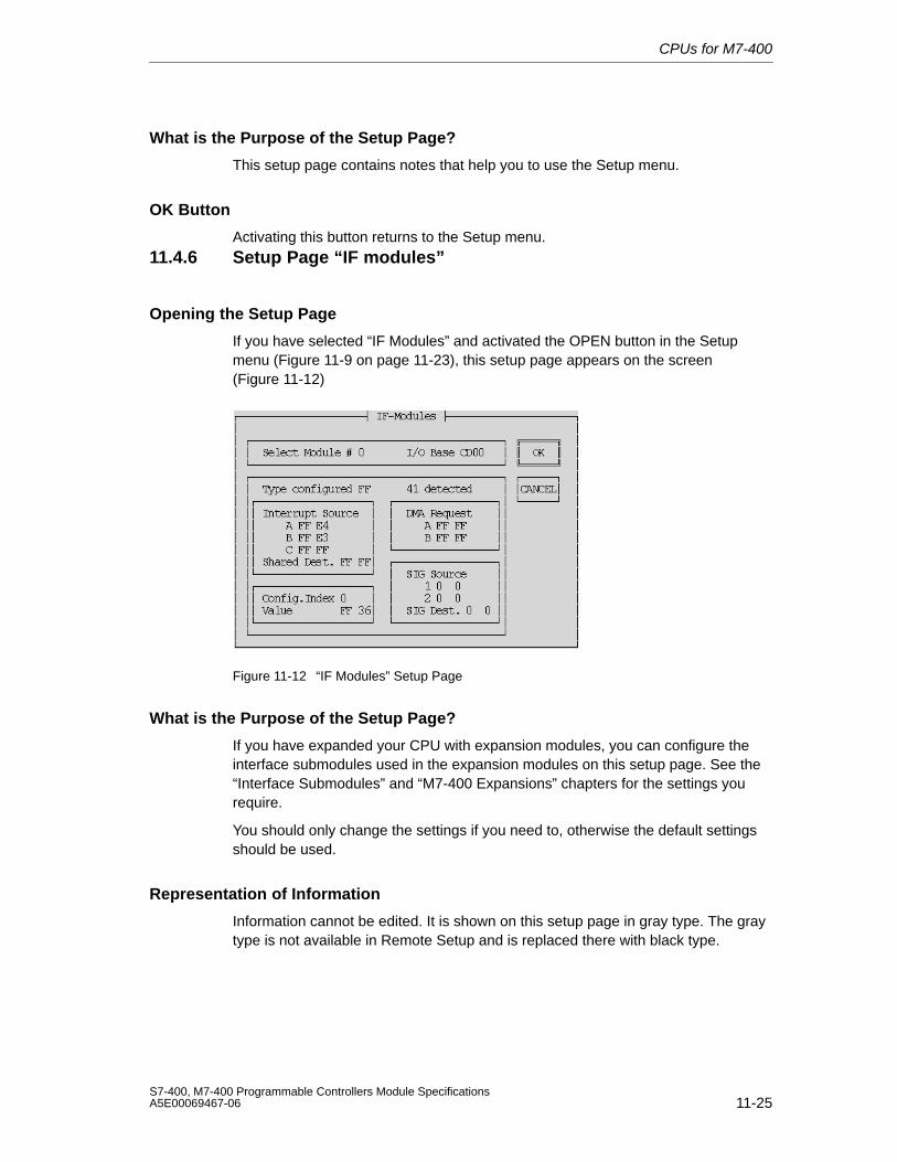
CPUs for M7-400
11-25S7-400, M7-400 Programmable Controllers Module SpecificationsA5E00069467-06
What is the Purpose of the Setup Page?
This setup page contains notes that help you to use the Setup menu.
OK Button
Activating this button returns to the Setup menu.
11.4.6 Setup Page “IF modules”
Opening the Setup Page
If you have selected “IF Modules” and activated the OPEN button in the Setupmenu (Figure 11-9 on page 11-23), this setup page appears on the screen(Figure 11-12)
Figure 11-12 “IF Modules” Setup Page
What is the Purpose of the Setup Page?
If you have expanded your CPU with expansion modules, you can configure theinterface submodules used in the expansion modules on this setup page. See the“Interface Submodules” and “M7-400 Expansions” chapters for the settings yourequire.
You should only change the settings if you need to, otherwise the default settingsshould be used.
Representation of Information
Information cannot be edited. It is shown on this setup page in gray type. The graytype is not available in Remote Setup and is replaced there with black type.
CPUs for M7-400
11-26S7-400, M7-400 Programmable Controllers Module Specifications
A5E00069467-06
Accepting Edited Values
Only the values for which the relevant interface submodule has been designed areaccepted by the system in the edit boxes. If, for example, you enter three valuesunder “Interrupt Source” and the interface submodule only has one interrupt, onlythe first value will be significant.
Any changed values are only saved when you confirm them with the key or
with – (only locally, not under Remote Setup).
Select Submodule Number
Here, you enter the consecutive number for the submodule receptacle containingthe interface submodule or you select the number using the cursor control keys
↑↓ .
In the M7-400, you can enter submodule receptacle numbers 0 to 14 if themaximum possible three EXM 478 expansion modules are in use (seeSection 12.2) Three submodule receptacle numbers are used per slot on thebackplane bus.
The submodule receptacle number is linked to the other values on this setup page.If you change the submodule receptacle number, the associated values alsoappear, if they have been entered.
I/O Base (Gray Type)
Shows the current address of the expansion module (see Chapter 12 “M7-400Expansions”) or CPU associated with the submodule receptacle. However, thedouble-width CPU has two addresses, one address for submodule receptacles inits left half and a second address, higher by + 100H for the submodule receptaclein its right half. The information cannot be edited.
Type Configured + Detected (Gray Type)
At “Type configured,” you enter the type of interface submodule already pluggedinto this slot or still to be plugged in.
“Detected” indicates the type of interface submodule currently (at the last CPUpower up) occupying this slot. The information cannot be edited.
The BIOS executes a SETPOINT/ACTUAL VALUE comparison. If the value set in“Type configured” does not agree with the value in “detected”, or if the value 0FFHhas been configured in “Type configured”, the BIOS does not execute theconfiguration for this interface submodule.
If there is no interface submodule in the submodule receptacle, the value “FF” isdisplayed.
CPUs for M7-400
11-27S7-400, M7-400 Programmable Controllers Module SpecificationsA5E00069467-06
Interrupt Source
Here, you set interrupts A to C (see the “Interface Submodules” chapter) providedfor the interface submodule. The values positioned on the left are setpoints. Youcan edit these. The value indicated in gray type to the right of these is the actualvalue (determined at the last CPU power up). It cannot be edited.
Note
For the IF 961-AIO, IF 961-DIO and IF 961-CT1 interface modules there are nodefault interrupts in the BIOS setup (default values are always 0xFF). Additionally,no error message is given if no interrupt is set for an interface module, which isconfigured for interrupt generation.
BIOS settings for interrupt capable interface modules
If you have set the interrupt generation for an interface module in the SIMATICmanager, you have to set an interrupt for this interface module in the BIOS setuppage “IF modules”. For this, use an available interrupt (see above and Table 11-9“Interrupt Assignment” on page 11-42).
Shared Dest.
Here, you set a shared interrupt for the interface submodule (see the “InterfaceSubmodules” and “M7-400 Expansions” chapters). This value is entered only onceper expansion module at the first submodule receptacle (0, 3, 6, 9, etc.). The valueon the left-hand side is the setpoint value, which you can edit. The value indicatedin gray type to the right of it is the actual value (determined at the last CPU powerup). It cannot be edited.
DMA Request
Enter here the DMA request A and B for the interface submodule (see the“Interface Submodules” chapter). The values positioned on the left are setpoints.You can edit these. The value indicated in gray type to the right of these is theactual value (determined at the last CPU power up). It cannot be edited.
Config. Index
Here, you can address the 40 H configuration space of the interface submodules(0H to 3FH). You will find the address in the Table “Offset Address for theConfiguration Register” of each interface submodule in the “Interface Submodules”chapter.
CPUs for M7-400
11-28S7-400, M7-400 Programmable Controllers Module Specifications
A5E00069467-06
Value (Gray Type)
Under the address set with “Config. Index”, you can now enter the configurationvalue. You will find this value and its significance in the chapter “InterfaceSubmodules” under the relevant interface submodule.
The configuration value positioned on the left is the setpoint. You can edit thisvalue. When you have entered it, confirm by pressing the '( key or the key
combination )!* '( , so that it is accepted. The configuration value shownto the right of this in gray type (black type in Remote Setup) is the actual value(determined at the last power up of the CPU). It cannot be edited. If there is nosubmodule in the submodule receptacle, the value “FF” is displayed.
SIG Source
Here, you enter the signal source if the relevant interface submodule is designedfor it (“Interface Submodules” chapter). The values for the signal source positionedon the left are the setpoints. You can edit these. The values shown to the right ofthis in gray type (black type in Remote Setup) are the actual values (determined atthe last power up of the CPU).
SIG Dest.
Here you enter the signal destination if the relevant interface submodule isdesigned for it (“Interface Submodules” chapter). This value is entered only onceper expansion module at the first submodule receptacle (0, 3, 6, 9, etc.). The valuefor the signal destination positioned on the left is the setpoint. You can edit thisvalue. The signal destination value shown to the right of this in gray type (blacktype in Remote Setup) is the actual value (determined at the last power up of theCPU). It cannot be edited.
OK Button
Returns to the Setup menu when activated. Changes on the setup page areretained.
CANCEL Button
Returns to the Setup menu when activated. Deletes all changes you have made onthe setup page.
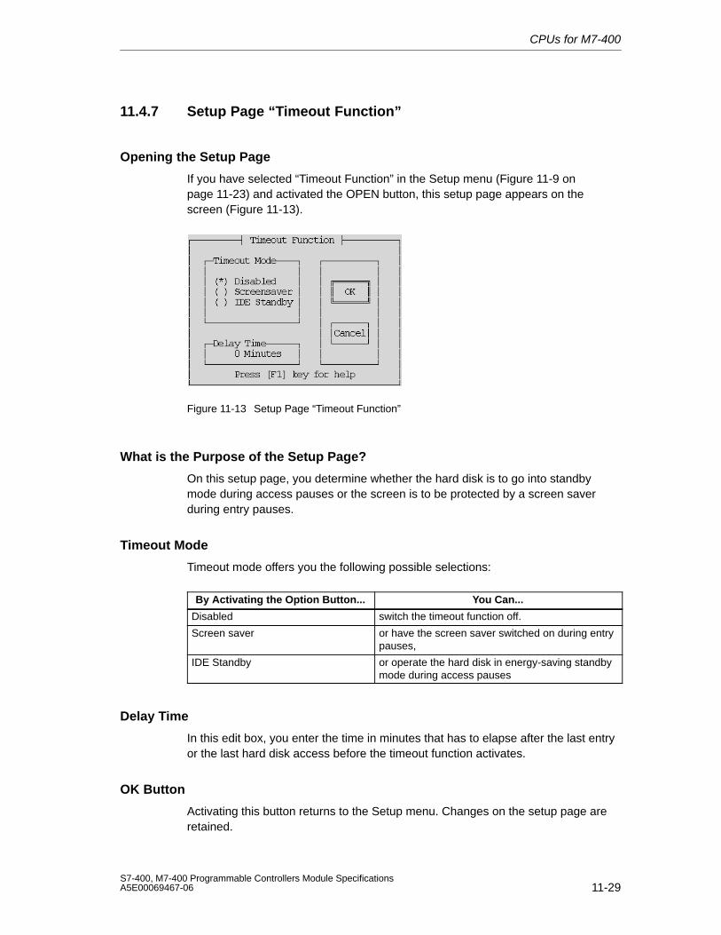
CPUs for M7-400
11-29S7-400, M7-400 Programmable Controllers Module SpecificationsA5E00069467-06
11.4.7 Setup Page “Timeout Function”
Opening the Setup Page
If you have selected “Timeout Function” in the Setup menu (Figure 11-9 onpage 11-23) and activated the OPEN button, this setup page appears on thescreen (Figure 11-13).
Figure 11-13 Setup Page “Timeout Function”
What is the Purpose of the Setup Page?
On this setup page, you determine whether the hard disk is to go into standbymode during access pauses or the screen is to be protected by a screen saverduring entry pauses.
Timeout Mode
Timeout mode offers you the following possible selections:
By Activating the Option Button... You Can...
Disabled switch the timeout function off.
Screen saver or have the screen saver switched on during entrypauses,
IDE Standby or operate the hard disk in energy-saving standbymode during access pauses
Delay Time
In this edit box, you enter the time in minutes that has to elapse after the last entryor the last hard disk access before the timeout function activates.
OK Button
Activating this button returns to the Setup menu. Changes on the setup page areretained.
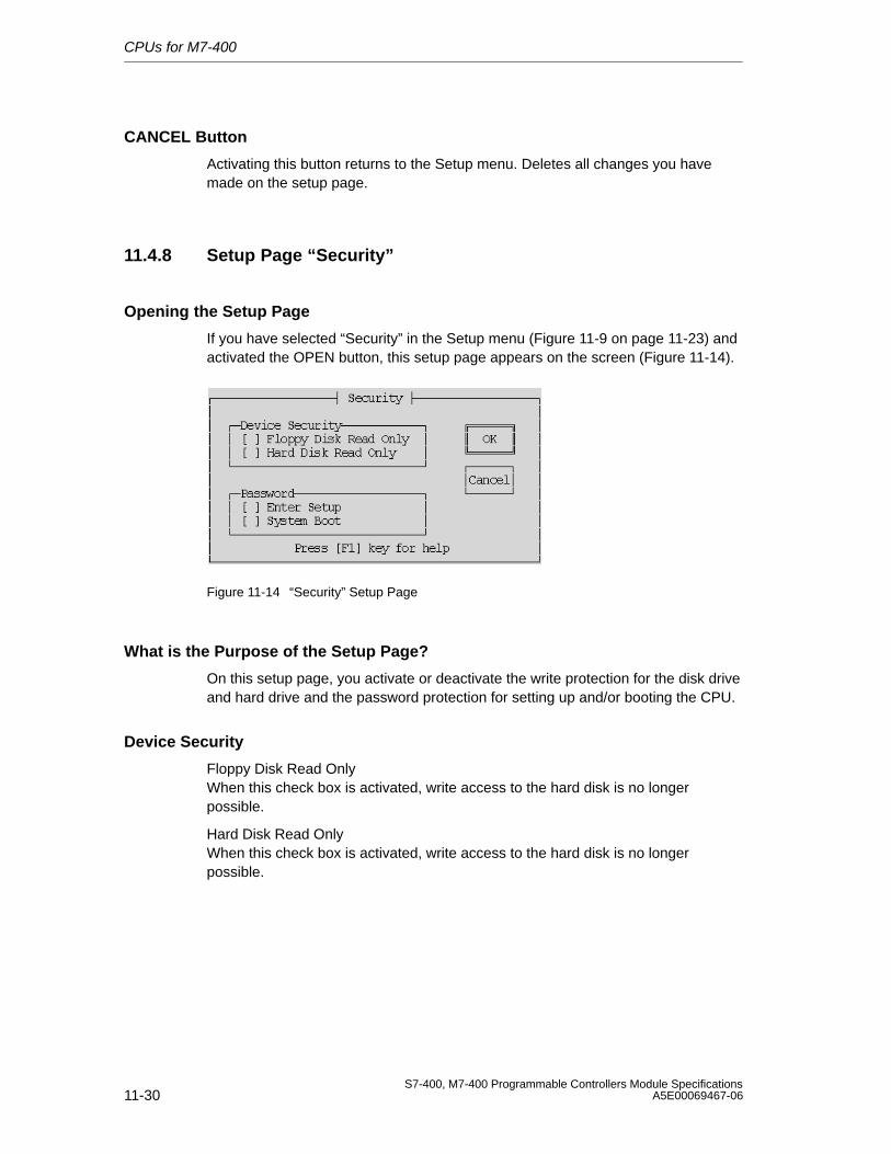
CPUs for M7-400
11-30S7-400, M7-400 Programmable Controllers Module Specifications
A5E00069467-06
CANCEL Button
Activating this button returns to the Setup menu. Deletes all changes you havemade on the setup page.
11.4.8 Setup Page “Security”
Opening the Setup Page
If you have selected “Security” in the Setup menu (Figure 11-9 on page 11-23) andactivated the OPEN button, this setup page appears on the screen (Figure 11-14).
Figure 11-14 “Security” Setup Page
What is the Purpose of the Setup Page?
On this setup page, you activate or deactivate the write protection for the disk driveand hard drive and the password protection for setting up and/or booting the CPU.
Device Security
Floppy Disk Read OnlyWhen this check box is activated, write access to the hard disk is no longerpossible.
Hard Disk Read OnlyWhen this check box is activated, write access to the hard disk is no longerpossible.
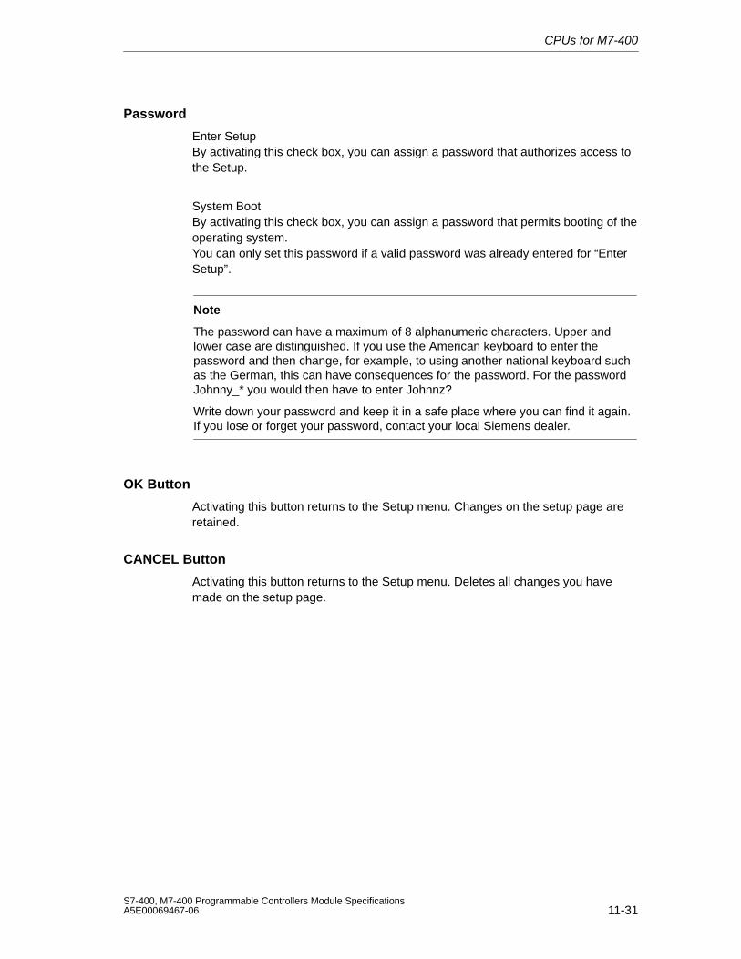
CPUs for M7-400
11-31S7-400, M7-400 Programmable Controllers Module SpecificationsA5E00069467-06
Password
Enter SetupBy activating this check box, you can assign a password that authorizes access tothe Setup.
System BootBy activating this check box, you can assign a password that permits booting of theoperating system.You can only set this password if a valid password was already entered for “EnterSetup”.
Note
The password can have a maximum of 8 alphanumeric characters. Upper andlower case are distinguished. If you use the American keyboard to enter thepassword and then change, for example, to using another national keyboard suchas the German, this can have consequences for the password. For the passwordJohnny_* you would then have to enter Johnnz?
Write down your password and keep it in a safe place where you can find it again.If you lose or forget your password, contact your local Siemens dealer.
OK Button
Activating this button returns to the Setup menu. Changes on the setup page areretained.
CANCEL Button
Activating this button returns to the Setup menu. Deletes all changes you havemade on the setup page.
CPUs for M7-400
11-32S7-400, M7-400 Programmable Controllers Module Specifications
A5E00069467-06
11.4.9 Setup Page “Date and Time”
Opening the Setup Page
If you have selected “Date and Time” and activated the OPEN button in the Setupmenu (Figure 11-9 on page 11-23), this BIOS setup page appears on the screen(Figure 11-15).
Figure 11-15 “Date and Time” Setup Page (Default)
What is the Purpose of the Setup Page?
On this setup page, you set the date and time for the programmable module.
Date
You enter the date in the form dd-mm-yyyy (day, month, year) in this edit box.
Time
You enter the time in the form hh:mm:ss (hour, minute, second) in this edit box.
The seconds in the setup page are updated continuously and only stopped whenyou select the seconds field. You can then accept the value displayed or set bypressing the # key.
OK Button
Activating this button returns to the Setup menu. Changes on the setup page areretained.
CANCEL Button
Activating this button returns to the Setup menu. Deletes all changes you havemade on the setup page with the exception of the time.
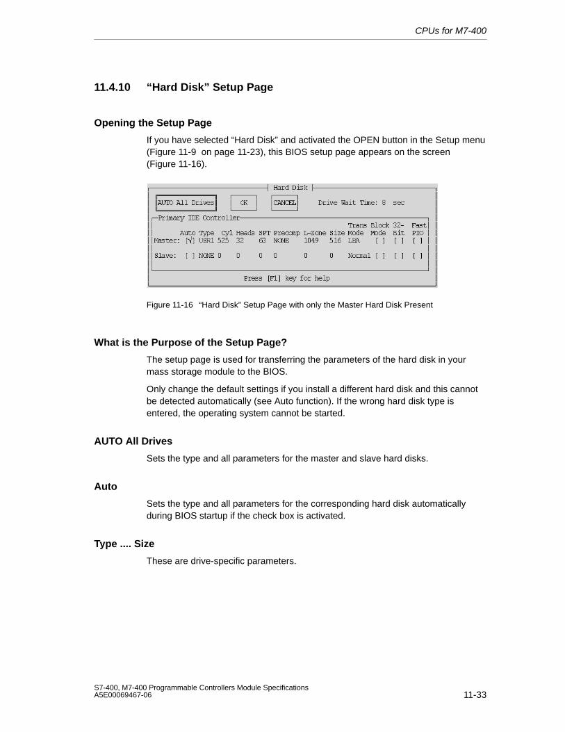
CPUs for M7-400
11-33S7-400, M7-400 Programmable Controllers Module SpecificationsA5E00069467-06
11.4.10 “Hard Disk” Setup Page
Opening the Setup Page
If you have selected “Hard Disk” and activated the OPEN button in the Setup menu(Figure 11-9 on page 11-23), this BIOS setup page appears on the screen(Figure 11-16).
Figure 11-16 “Hard Disk” Setup Page with only the Master Hard Disk Present
What is the Purpose of the Setup Page?
The setup page is used for transferring the parameters of the hard disk in yourmass storage module to the BIOS.
Only change the default settings if you install a different hard disk and this cannotbe detected automatically (see Auto function). If the wrong hard disk type isentered, the operating system cannot be started.
AUTO All Drives
Sets the type and all parameters for the master and slave hard disks.
Auto
Sets the type and all parameters for the corresponding hard disk automaticallyduring BIOS startup if the check box is activated.
Type .... Size
These are drive-specific parameters.
CPUs for M7-400
11-34S7-400, M7-400 Programmable Controllers Module Specifications
A5E00069467-06
Translation Mode
In Translation Mode you have four possible settings:
• Autoreads the hard disk parameters and automatically sets the correct mode(Normal, LBA, Large). The Translation Mode “Auto” is set as the default.
• Normalused for hard disks with a memory capacity of 504 Mbytes.
• LBA (Logical Block Addressing)is used for hard disks with a memory capacity of 504 Mbytes.
• Largemust be set for hard disks with a memory capacity of 504 Mbytes which do notsupport the LBA mode.
Block Mode
Sets the block mode for DMA transfers. As the hard disks in the M7-400 are notbeing operated in DMA mode, this check box should not be activated.
32 Bits
Sets 32-bit access mode. As this is not supported by ISA hard disk controllers, thischeck box should not be activated.
Fast PIO
Sets a faster Programmed Input Output mode.
OK Button
Activating this button returns to the Setup menu. Changes on the setup page areretained.
CANCEL Button
Activating this button returns to the Setup menu. Deletes all changes you havemade on the setup page.
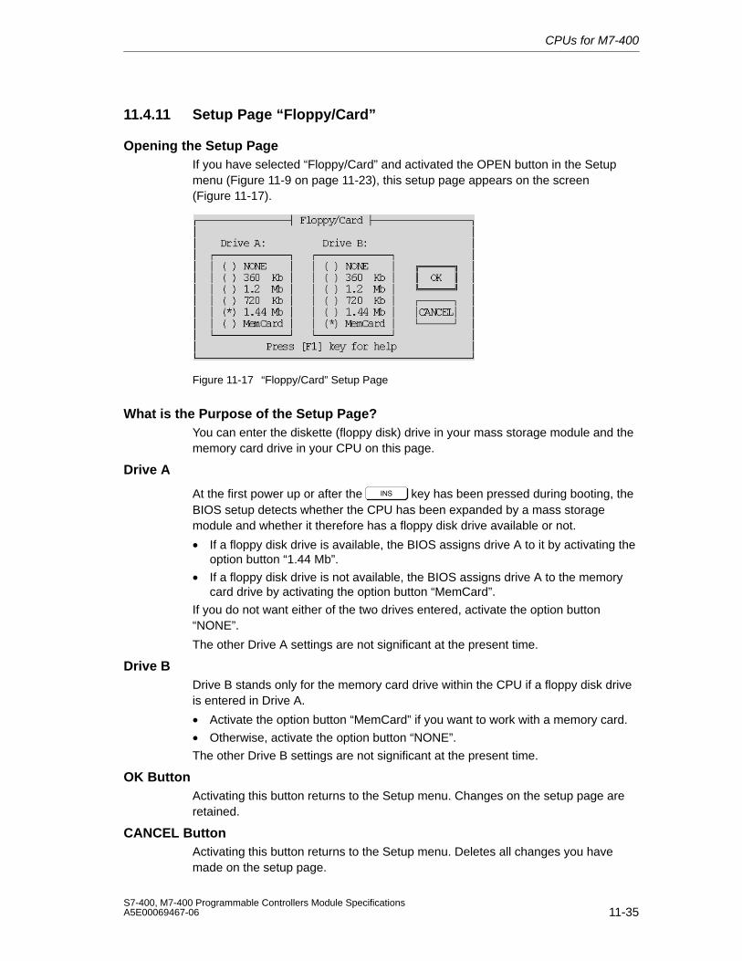
CPUs for M7-400
11-35S7-400, M7-400 Programmable Controllers Module SpecificationsA5E00069467-06
11.4.11 Setup Page “Floppy/Card”
Opening the Setup PageIf you have selected “Floppy/Card” and activated the OPEN button in the Setupmenu (Figure 11-9 on page 11-23), this setup page appears on the screen(Figure 11-17).
Figure 11-17 “Floppy/Card” Setup Page
What is the Purpose of the Setup Page?You can enter the diskette (floppy disk) drive in your mass storage module and thememory card drive in your CPU on this page.
Drive A
At the first power up or after the key has been pressed during booting, theBIOS setup detects whether the CPU has been expanded by a mass storagemodule and whether it therefore has a floppy disk drive available or not.
• If a floppy disk drive is available, the BIOS assigns drive A to it by activating theoption button “1.44 Mb”.
• If a floppy disk drive is not available, the BIOS assigns drive A to the memorycard drive by activating the option button “MemCard”.
If you do not want either of the two drives entered, activate the option button“NONE”.
The other Drive A settings are not significant at the present time.
Drive BDrive B stands only for the memory card drive within the CPU if a floppy disk driveis entered in Drive A.
• Activate the option button “MemCard” if you want to work with a memory card.
• Otherwise, activate the option button “NONE”.
The other Drive B settings are not significant at the present time.
OK ButtonActivating this button returns to the Setup menu. Changes on the setup page areretained.
CANCEL ButtonActivating this button returns to the Setup menu. Deletes all changes you havemade on the setup page.
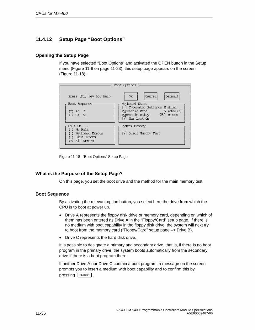
CPUs for M7-400
11-36S7-400, M7-400 Programmable Controllers Module Specifications
A5E00069467-06
11.4.12 Setup Page “Boot Options”
Opening the Setup Page
If you have selected “Boot Options” and activated the OPEN button in the Setupmenu (Figure 11-9 on page 11-23), this setup page appears on the screen(Figure 11-18).
Figure 11-18 “Boot Options” Setup Page
What is the Purpose of the Setup Page?
On this page, you set the boot drive and the method for the main memory test.
Boot Sequence
By activating the relevant option button, you select here the drive from which theCPU is to boot at power up.
• Drive A represents the floppy disk drive or memory card, depending on which ofthem has been entered as Drive A in the “Floppy/Card” setup page. If there isno medium with boot capability in the floppy disk drive, the system will next tryto boot from the memory card (“Floppy/Card” setup page –> Drive B).
• Drive C represents the hard disk drive.
It is possible to designate a primary and secondary drive, that is, if there is no bootprogram in the primary drive, the system boots automatically from the secondarydrive if there is a boot program there.
If neither Drive A nor Drive C contain a boot program, a message on the screenprompts you to insert a medium with boot capability and to confirm this bypressing # .
CPUs for M7-400
11-37S7-400, M7-400 Programmable Controllers Module SpecificationsA5E00069467-06
Halt On ...
Here you can choose which error messages are displayed in an error windowduring booting. Displaying an error window delays booting by approximately2 seconds.
Keyboard State
Typematic Settings EnabledIf you activate this check box, the values “Typematic Rate” and “Typematic Delay”are set by the BIOS.
Typematic RateThis value is used to set the maximum keyboard rate in characters per second.
Typematic DelayThis value is used to set the delay time in milliseconds, after which characters aretransferred with the maximum keyboard rate.
Num Lock OnIf you activate this check box, “Num Lock” becomes active after BIOS power up.
System Memory
If this check box is activated, only sample tests are made of the main memory atpower up so the test is especially fast.
OK Button
Activating this button returns to the Setup menu. Changes on the setup page areretained.
CANCEL Button
Activating this button returns to the Setup menu. Deletes all changes you havemade on the setup page.
DEFAULT Button
When this button is activated, the default settings are entered in the setup pageagain. The original settings are deleted.
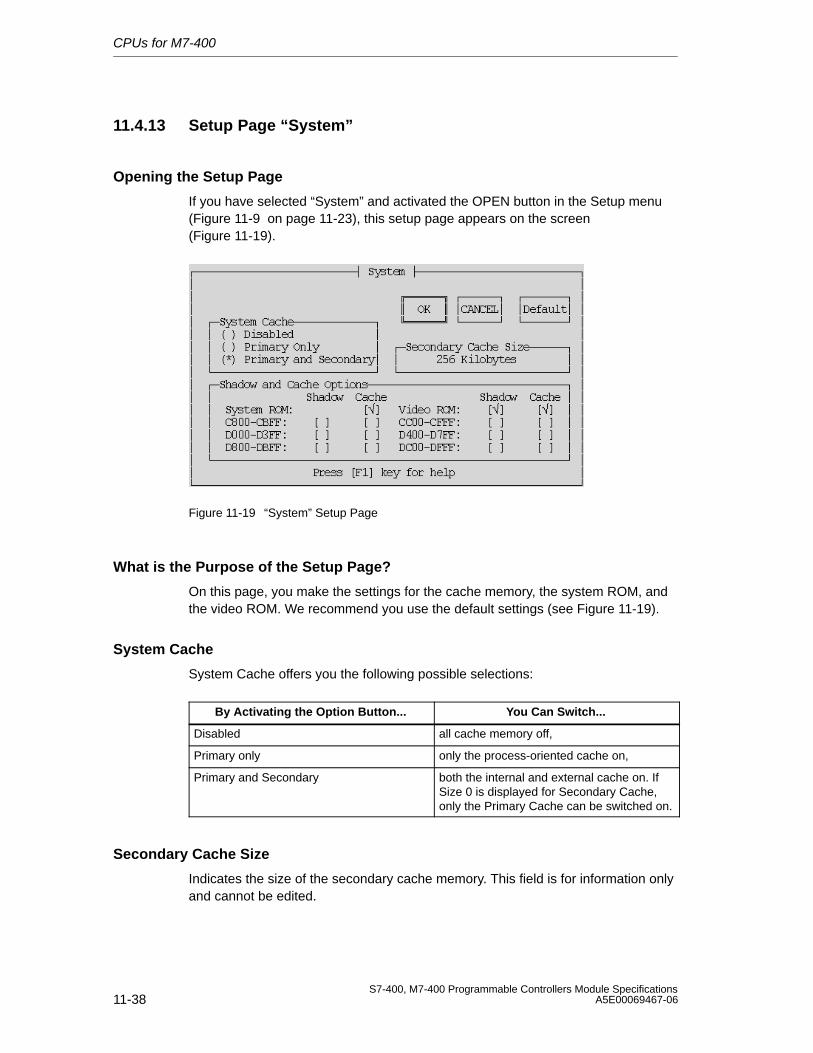
CPUs for M7-400
11-38S7-400, M7-400 Programmable Controllers Module Specifications
A5E00069467-06
11.4.13 Setup Page “System”
Opening the Setup Page
If you have selected “System” and activated the OPEN button in the Setup menu(Figure 11-9 on page 11-23), this setup page appears on the screen(Figure 11-19).
Figure 11-19 “System” Setup Page
What is the Purpose of the Setup Page?
On this page, you make the settings for the cache memory, the system ROM, andthe video ROM. We recommend you use the default settings (see Figure 11-19).
System Cache
System Cache offers you the following possible selections:
By Activating the Option Button... You Can Switch...
Disabled all cache memory off,
Primary only only the process-oriented cache on,
Primary and Secondary both the internal and external cache on. IfSize 0 is displayed for Secondary Cache,only the Primary Cache can be switched on.
Secondary Cache Size
Indicates the size of the secondary cache memory. This field is for information onlyand cannot be edited.
CPUs for M7-400
11-39S7-400, M7-400 Programmable Controllers Module SpecificationsA5E00069467-06
System Cache
For the memory areas of the System ROM, the VIDEO ROM, and the addresses ofBIOS expansions, you can set whether they are copied to the Shadow RAM andwhether the cache should be used.
• System ROM offers you the following possible selections:
By Activating the Option Button... You Determine...
Shadowed that the BIOS address area of 128 Kbytes isto be copied into the high-speed shadowRAM. This option cannot be switched off.
Shadowed and Cached that a cache memory is available for thismemory area in addition to shadow RAM.
Note
If you have switched off the cache memory in the “Primary and Secondary Cache”field, the setting in the “System ROM” field does not change automatically.
• Video ROM offers you the following possible selections:
By Activating the Option Button... You Determine...
Shadowed that the video ROM (32 Kbytes) is copiedinto the fast shadow RAM. This acceleratesvideo output (faster screen buildup).
Shadowed and Cached that a cache memory is available for thismemory area in addition to shadow RAM.Further accelerates video output.
OK Button
Activating this button returns to the Setup menu. Changes on the setup page areretained.
CANCEL Button
Activating this button returns to the Setup menu. Deletes all changes you havemade on the setup page.
DEFAULT Button
When this button is activated, the default settings are entered in the setup pageagain. The original settings are deleted.
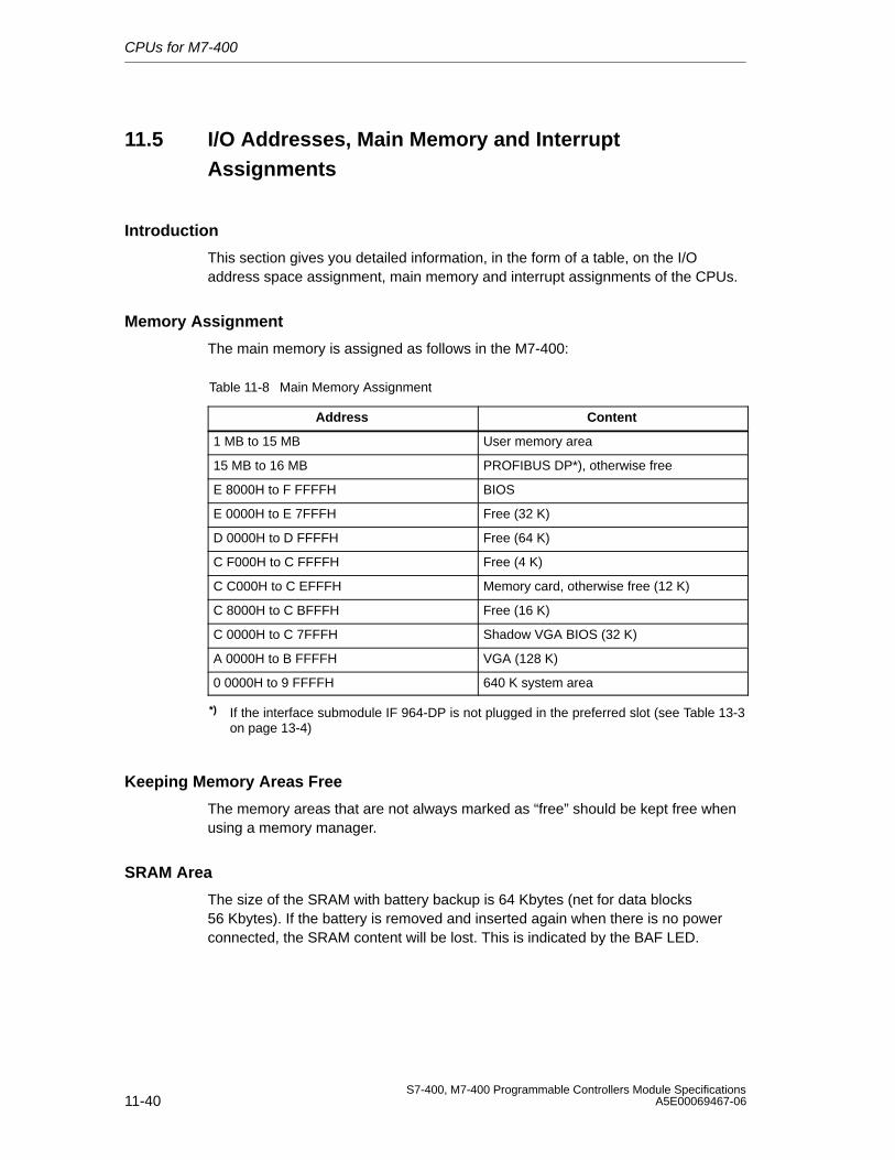
CPUs for M7-400
11-40S7-400, M7-400 Programmable Controllers Module Specifications
A5E00069467-06
11.5 I/O Addresses, Main Memory and InterruptAssignments
Introduction
This section gives you detailed information, in the form of a table, on the I/Oaddress space assignment, main memory and interrupt assignments of the CPUs.
Memory Assignment
The main memory is assigned as follows in the M7-400:
Table 11-8 Main Memory Assignment
Address Content
1 MB to 15 MB User memory area
15 MB to 16 MB PROFIBUS DP*), otherwise free
E 8000H to F FFFFH BIOS
E 0000H to E 7FFFH Free (32 K)
D 0000H to D FFFFH Free (64 K)
C F000H to C FFFFH Free (4 K)
C C000H to C EFFFH Memory card, otherwise free (12 K)
C 8000H to C BFFFH Free (16 K)
C 0000H to C 7FFFH Shadow VGA BIOS (32 K)
A 0000H to B FFFFH VGA (128 K)
0 0000H to 9 FFFFH 640 K system area
*) If the interface submodule IF 964-DP is not plugged in the preferred slot (see Table 13-3on page 13-4)
Keeping Memory Areas Free
The memory areas that are not always marked as “free” should be kept free whenusing a memory manager.
SRAM Area
The size of the SRAM with battery backup is 64 Kbytes (net for data blocks56 Kbytes). If the battery is removed and inserted again when there is no powerconnected, the SRAM content will be lost. This is indicated by the BAF LED.
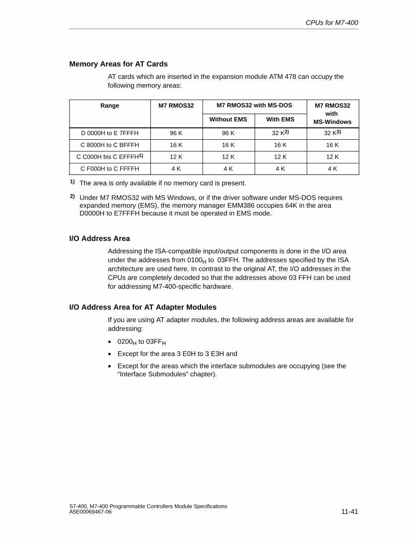
CPUs for M7-400
11-41S7-400, M7-400 Programmable Controllers Module SpecificationsA5E00069467-06
Memory Areas for AT Cards
AT cards which are inserted in the expansion module ATM 478 can occupy thefollowing memory areas:
Range M7 RMOS32 M7 RMOS32 with MS-DOS M7 RMOS32
Without EMS With EMSwith
MS-Windows
D 0000H to E 7FFFH 96 K 96 K 32 K2) 32 K2)
C 8000H to C BFFFH 16 K 16 K 16 K 16 K
C C000H bis C EFFFH1) 12 K 12 K 12 K 12 K
C F000H to C FFFFH 4 K 4 K 4 K 4 K
1) The area is only available if no memory card is present.
2) Under M7 RMOS32 with MS Windows, or if the driver software under MS-DOS requiresexpanded memory (EMS), the memory manager EMM386 occupies 64K in the areaD0000H to E7FFFH because it must be operated in EMS mode.
I/O Address Area
Addressing the ISA-compatible input/output components is done in the I/O areaunder the addresses from 0100H to 03FFH. The addresses specified by the ISAarchitecture are used here. In contrast to the original AT, the I/O addresses in theCPUs are completely decoded so that the addresses above 03 FFH can be usedfor addressing M7-400-specific hardware.
I/O Address Area for AT Adapter Modules
If you are using AT adapter modules, the following address areas are available foraddressing:
• 0200H to 03FFH
• Except for the area 3 E0H to 3 E3H and
• Except for the areas which the interface submodules are occupying (see the“Interface Submodules” chapter).
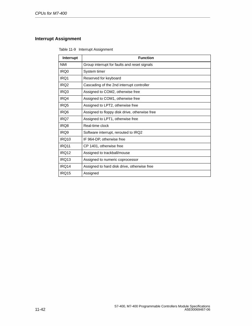
CPUs for M7-400
11-42S7-400, M7-400 Programmable Controllers Module Specifications
A5E00069467-06
Interrupt Assignment
Table 11-9 Interrupt Assignment
Interrupt Function
NMI Group interrupt for faults and reset signals
IRQ0 System timer
IRQ1 Reserved for keyboard
IRQ2 Cascading of the 2nd interrupt controller
IRQ3 Assigned to COM2, otherwise free
IRQ4 Assigned to COM1, otherwise free
IRQ5 Assigned to LPT2, otherwise free
IRQ6 Assigned to floppy disk drive, otherwise free
IRQ7 Assigned to LPT1, otherwise free
IRQ8 Real-time clock
IRQ9 Software interrupt, rerouted to IRQ2
IRQ10 IF 964-DP, otherwise free
IRQ11 CP 1401, otherwise free
IRQ12 Assigned to trackball/mouse
IRQ13 Assigned to numeric coprocessor
IRQ14 Assigned to hard disk drive, otherwise free
IRQ15 Assigned
12-1S7-400, M7-400 Programmable Controllers Module SpecificationsA5E00069467-06
M7-400 Expansions
Chapter Overview
Section Description Page
12.1 Overview 12-2
12.2 EXM 478 Expansion Module; (6ES7 478-2AC00-0AC0) 12-6
12.3 ATM 478 AT Adapter Module; (6ES7 478-2CA00-0AC0) 12-15
12.4 MSM 478 Mass Storage Module; (6ES7 478-2BA00-0AC0) 12-22
12
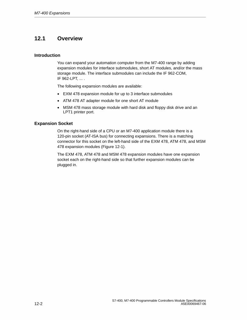
M7-400 Expansions
12-2S7-400, M7-400 Programmable Controllers Module Specifications
A5E00069467-06
12.1 Overview
Introduction
You can expand your automation computer from the M7-400 range by addingexpansion modules for interface submodules, short AT modules, and/or the massstorage module. The interface submodules can include the IF 962-COM,IF 962-LPT, ... .
The following expansion modules are available:
• EXM 478 expansion module for up to 3 interface submodules
• ATM 478 AT adapter module for one short AT module
• MSM 478 mass storage module with hard disk and floppy disk drive and anLPT1 printer port.
Expansion Socket
On the right-hand side of a CPU or an M7-400 application module there is a120-pin socket (AT-ISA bus) for connecting expansions. There is a matchingconnector for this socket on the left-hand side of the EXM 478, ATM 478, and MSM478 expansion modules (Figure 12-1).
The EXM 478, ATM 478 and MSM 478 expansion modules have one expansionsocket each on the right-hand side so that further expansion modules can beplugged in.
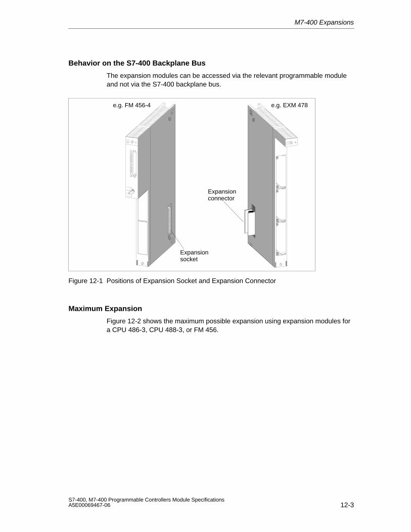
M7-400 Expansions
12-3S7-400, M7-400 Programmable Controllers Module SpecificationsA5E00069467-06
Behavior on the S7-400 Backplane Bus
The expansion modules can be accessed via the relevant programmable moduleand not via the S7-400 backplane bus.
e.g. FM 456-4 e.g. EXM 478
Expansionsocket
Expansionconnector
Figure 12-1 Positions of Expansion Socket and Expansion Connector
Maximum Expansion
Figure 12-2 shows the maximum possible expansion using expansion modules fora CPU 486-3, CPU 488-3, or FM 456.
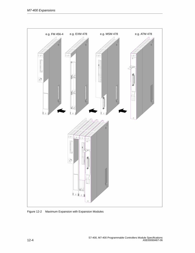
M7-400 Expansions
12-4S7-400, M7-400 Programmable Controllers Module Specifications
A5E00069467-06
e.g. FM 456-4 e.g. EXM 478 e.g. ATM 478e.g. MSM 478
Figure 12-2 Maximum Expansion with Expansion Modules
M7-400 Expansions
12-5S7-400, M7-400 Programmable Controllers Module SpecificationsA5E00069467-06
Permissible Combinations
You can see from the table below which expansions can be connected to theprogrammable M7-400 modules.
Table 12-1 Expansion Possibilities of the CPU 486-3, CPU 488-3, or FM 456
Programmable M7-400 Module Slot Slot Slot
Slot n in the Case of Single-Width Modules n + 1 n + 2 n + 3
Slot n and n+1 in the Case of Double-Width Modules
n + 2 n + 3 n + 4
– – –
EXM 478 – –
EXM 478 EXM 478 –
EXM 478 EXM 478 EXM 478
EXM 478 EXM 478 ATM 478
EXM 478 ATM 478 ATM 478
EXM 478 ATM 478 –
ATM 478 – –CPU 486-3, CPU 488-3, FM 456-4
ATM 478 ATM 478 –
ATM 478 ATM 478 ATM 478
MSM 478 – –
EXM 478 MSM 478 –
EXM 478 EXM 478 MSM 478
EXM 478 MSM 478 ATM 478
MSM 478 ATM 478 ATM 478
MSM 478 ATM 478 –
Rules for the Combinations
The following rules apply for expansions from left to right after a CPU or applicationmodule (slots n + 1, n + 2, n + 3 or n + 2, n + 3, n + 4):
1. Up to 3 EXM 478 expansion modules
2. Max. 1 MSM 478 mass storage module
(that is, always after the CPU 486-3, CPU 488-3, FM 456, or EXM 478)
3. Up to 3 ATM 478 AT adapter modules
(that is, always after the CPU 486-3, CPU 488-3, FM 456, EXM 478, orMSM 478)
In total, a CPU or application module can be expanded with up to three modules.
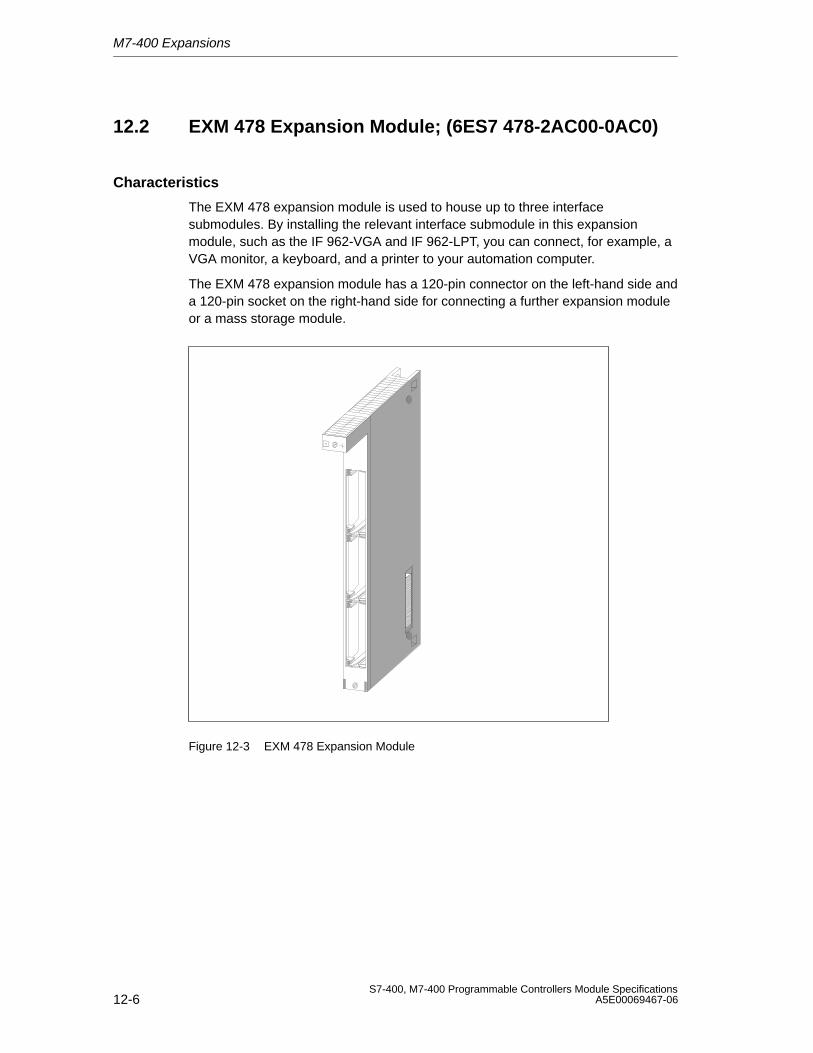
M7-400 Expansions
12-6S7-400, M7-400 Programmable Controllers Module Specifications
A5E00069467-06
12.2 EXM 478 Expansion Module; (6ES7 478-2AC00-0AC0)
Characteristics
The EXM 478 expansion module is used to house up to three interfacesubmodules. By installing the relevant interface submodule in this expansionmodule, such as the IF 962-VGA and IF 962-LPT, you can connect, for example, aVGA monitor, a keyboard, and a printer to your automation computer.
The EXM 478 expansion module has a 120-pin connector on the left-hand side anda 120-pin socket on the right-hand side for connecting a further expansion moduleor a mass storage module.
Figure 12-3 EXM 478 Expansion Module
M7-400 Expansions
12-7S7-400, M7-400 Programmable Controllers Module SpecificationsA5E00069467-06
12.2.1 Addressing the EXM 478 Expansion Module
Introduction
In order to be able to program the interface submodules in the EXM 478 expansionmodule, you must be able to determine their addresses. There are the followingaddressing methods:
• Addressing in the AT-compatible I/O address area
• Addressing in the M7-400-specific I/O address area
In this section, you will find information on both methods of addressing the interfacesubmodules.
Addressing in the AT-Compatible I/O Address Area
Some of the interface submodules are automatically configured by the BIOS foroperation in the AT-compatible I/O address area. This automatic configurationtakes place, for example, for:
• The IF 962-VGA interface submodule
• Up to 4 COM ports (COM1 to COM4)
• Up to 3 LPT ports (one LPT port on the MSM 478 and two interface submodulesIF 962-LPT)
Further interfaces are configured in the BIOS setup. See the CPU/FM descriptionto learn how to operate the BIOS setup. The description of the interfacesubmodules will show the specific settings possible.
To configure in the BIOS setup, you must know the submodule receptacle numbersof the interface submodule receptacles (slots). You will find this information inFigure 12-4 later in this section.
Addressing in the M7-400-Specific I/O Address Area
All interface submodules can be accessed via M7-400-specific I/O addresses.There is a description of how to determine the I/O address of an interfacesubmodule in the “specific address area” starting from page 12-10.
You require this information to program an interface submodule that is notaddressed in the AT-compatible address area.
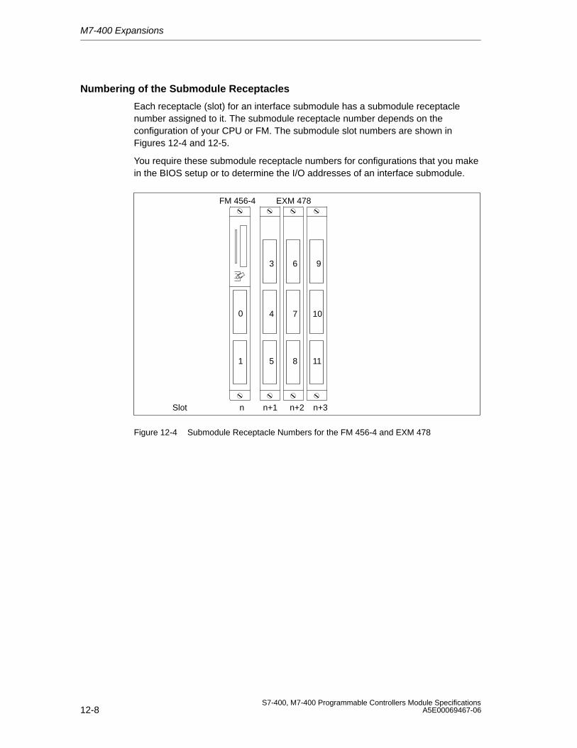
M7-400 Expansions
12-8S7-400, M7-400 Programmable Controllers Module Specifications
A5E00069467-06
Numbering of the Submodule Receptacles
Each receptacle (slot) for an interface submodule has a submodule receptaclenumber assigned to it. The submodule receptacle number depends on theconfiguration of your CPU or FM. The submodule slot numbers are shown inFigures 12-4 and 12-5.
You require these submodule receptacle numbers for configurations that you makein the BIOS setup or to determine the I/O addresses of an interface submodule.
0
1 5
3
4
6 9
7 10
8 11
FM 456-4 EXM 478
Slot n n+1 n+2 n+3
Figure 12-4 Submodule Receptacle Numbers for the FM 456-4 and EXM 478
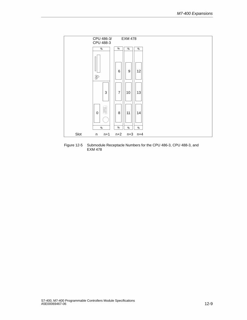
M7-400 Expansions
12-9S7-400, M7-400 Programmable Controllers Module SpecificationsA5E00069467-06
3
0 8
6
7
9 12
10 13
11 14
CPU 486-3/CPU 488-3
EXM 478
Slot n n+2 n+3 n+4n+1
Figure 12-5 Submodule Receptacle Numbers for the CPU 486-3, CPU 488-3, andEXM 478
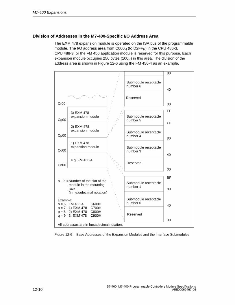
M7-400 Expansions
12-10S7-400, M7-400 Programmable Controllers Module Specifications
A5E00069467-06
Division of Addresses in the M7-400-Specific I/O Address Area
The EXM 478 expansion module is operated on the ISA bus of the programmablemodule. The I/O address area from C000H (to D2FFH) in the CPU 486-3,CPU 488-3, or the FM 456 application module is reserved for this purpose. Eachexpansion module occupies 256 bytes (100H) in this area. The division of theaddress area is shown in Figure 12-6 using the FM 456-4 as an example.
Cn00
Co00
Cp00
Cq00
2) EXM 478expansion module
Submodule receptaclenumber 1
Reserved
00
40
80
All addresses are in hexadecimal notation.
Submodule receptaclenumber 5
Submodule receptaclenumber 4
Submodule receptaclenumber 3
00
40
80
C0
FF
1) EXM 478expansion module
e.g. FM 456-4
Cr00
3) EXM 478expansion module
Submodule receptaclenumber 0
Reserved
Submodule receptaclenumber 6
00
40
80
Reserved
n .. q =Number of the slot of the module in the mountingrack(in hexadecimal notation)
Example:n = 6 FM 456-4 C600Ho = 7 1) EXM 478 C700Hp = 8 2) EXM 478 C800Hq = 9 3. EXM 478 C900H
BF
Figure 12-6 Base Addresses of the Expansion Modules and the Interface Submodules
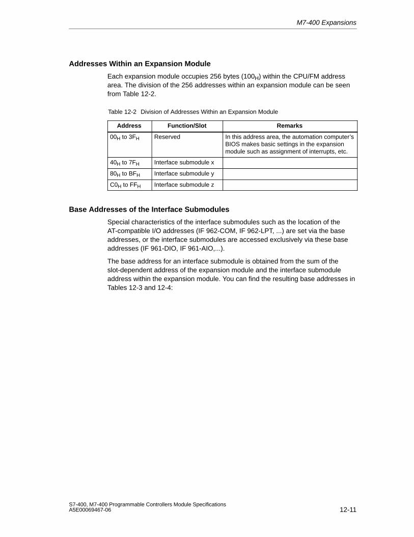
M7-400 Expansions
12-11S7-400, M7-400 Programmable Controllers Module SpecificationsA5E00069467-06
Addresses Within an Expansion Module
Each expansion module occupies 256 bytes (100H) within the CPU/FM addressarea. The division of the 256 addresses within an expansion module can be seenfrom Table 12-2.
Table 12-2 Division of Addresses Within an Expansion Module
Address Function/Slot Remarks
00H to 3FH Reserved In this address area, the automation computer’sBIOS makes basic settings in the expansionmodule such as assignment of interrupts, etc.
40H to 7FH Interface submodule x
80H to BFH Interface submodule y
C0H to FFH Interface submodule z
Base Addresses of the Interface Submodules
Special characteristics of the interface submodules such as the location of theAT-compatible I/O addresses (IF 962-COM, IF 962-LPT, ...) are set via the baseaddresses, or the interface submodules are accessed exclusively via these baseaddresses (IF 961-DIO, IF 961-AIO,...).
The base address for an interface submodule is obtained from the sum of theslot-dependent address of the expansion module and the interface submoduleaddress within the expansion module. You can find the resulting base addresses inTables 12-3 and 12-4:
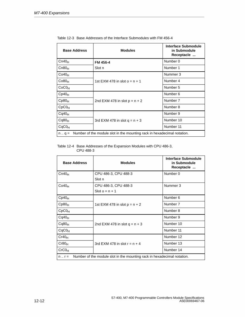
M7-400 Expansions
12-12S7-400, M7-400 Programmable Controllers Module Specifications
A5E00069467-06
Table 12-3 Base Addresses of the Interface Submodules with FM 456-4
Base Address ModulesInterface Submodule
in SubmoduleReceptacle ...
Cn40H FM 456-4 Number 0
Cn80H
FM 456-4
Slot n Number 1
Co40H Nummer 3
Co80H 1st EXM 478 in slot o = n + 1 Number 4
CoC0H Number 5
Cp40H Number 6
Cp80H 2nd EXM 478 in slot p = n + 2 Number 7
CpC0H Number 8
Cq40H Number 9
Cq80H 3rd EXM 478 in slot q = n + 3 Number 10
CqC0H Number 11
n .. q = Number of the module slot in the mounting rack in hexadecimal notation.
Table 12-4 Base Addresses of the Expansion Modules with CPU 486-3,CPU 488-3
Base Address ModulesInterface Submodule
in SubmoduleReceptacle ...
Cn40H CPU 486-3, CPU 488-3
Slot n
Number 0
Co40H CPU 486-3, CPU 488-3
Slot o = n + 1
Nummer 3
Cp40H Number 6
Cp80H 1st EXM 478 in slot p = n + 2 Number 7
CpC0H Number 8
Cq40H Number 9
Cq80H 2nd EXM 478 in slot q = n + 3 Number 10
CqC0H Number 11
Cr40H Number 12
Cr80H 3rd EXM 478 in slot r = n + 4 Number 13
CrC0H Number 14
n .. r = Number of the module slot in the mounting rack in hexadecimal notation.
M7-400 Expansions
12-13S7-400, M7-400 Programmable Controllers Module SpecificationsA5E00069467-06
12.2.2 Interrupt Assignments, Signal Switching EXM 478
Introduction
Up to three interrupts per interface submodule are permitted in an EXM 478expansion module. The various possible methods of interrupt assignment orinterrupt operation are described below.
Interrupt Assignment
When configuring the interface submodules in the BIOS setup, you can assign ISAinterrupts to the three interrupts of an interface submodule (IRQa, IRQb, IRQc). Forthis purpose, enter the ISA interrupt provided in the relevant screen form.
If you enter the value “F0H” instead of the ISA interrupt, this interrupt is processedvia a shared interrupt. See below for details.
Shared Interrupt
Since the number of interrupts is limited due to AT-compatibility, it is possible toassign several individual interrupts of the interface submodules to a sharedinterrupt in the EXM 478 expansion modules. The shared interrupt is shared by allinterface submodule interrupts within an expansion module where the interruptassignment “F0H” has been entered.
The shared interrupt is assigned to the ISA interrupt during configuration of theinterface submodule in the BIOS setup.
Signal Switching
In an EXM 478 expansion module, two interface submodule signals can beswitched to another (signal switching). This signal switching is done duringconfiguration of the interface submodule in the BIOS setup.
Refer to the interface submodule description to find out if an interface submodulerequires signals from a further interface submodule, that is, if signal switching isnecessary.
Note
You will find a detailed description of the BIOS setup in the M7-400 applicationmodule or CPU description.
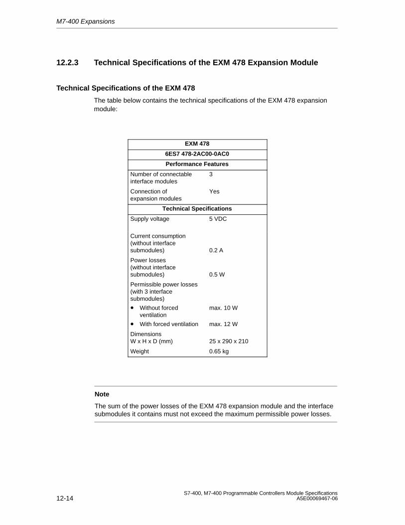
M7-400 Expansions
12-14S7-400, M7-400 Programmable Controllers Module Specifications
A5E00069467-06
12.2.3 Technical Specifications of the EXM 478 Expansion Module
Technical Specifications of the EXM 478
The table below contains the technical specifications of the EXM 478 expansionmodule:
EXM 478
6ES7 478-2AC00-0AC0
Performance Features
Number of connectableinterface modules
3
Connection ofexpansion modules
Yes
Technical Specifications
Supply voltage 5 VDC
Current consumption(without interfacesubmodules) 0.2 A
Power losses(without interfacesubmodules) 0.5 W
Permissible power losses(with 3 interfacesubmodules)
• Without forcedventilation
• With forced ventilation
max. 10 W
max. 12 W
DimensionsW x H x D (mm) 25 x 290 x 210
Weight 0.65 kg
Note
The sum of the power losses of the EXM 478 expansion module and the interfacesubmodules it contains must not exceed the maximum permissible power losses.
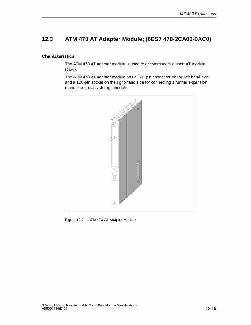
M7-400 Expansions
12-15S7-400, M7-400 Programmable Controllers Module SpecificationsA5E00069467-06
12.3 ATM 478 AT Adapter Module; (6ES7 478-2CA00-0AC0)
Characteristics
The ATM 478 AT adapter module is used to accommodate a short AT module(card).
The ATM 478 AT adapter module has a 120-pin connector on the left-hand sideand a 120-pin socket on the right-hand side for connecting a further expansionmodule or a mass storage module.
Figure 12-7 ATM 478 AT Adapter Module
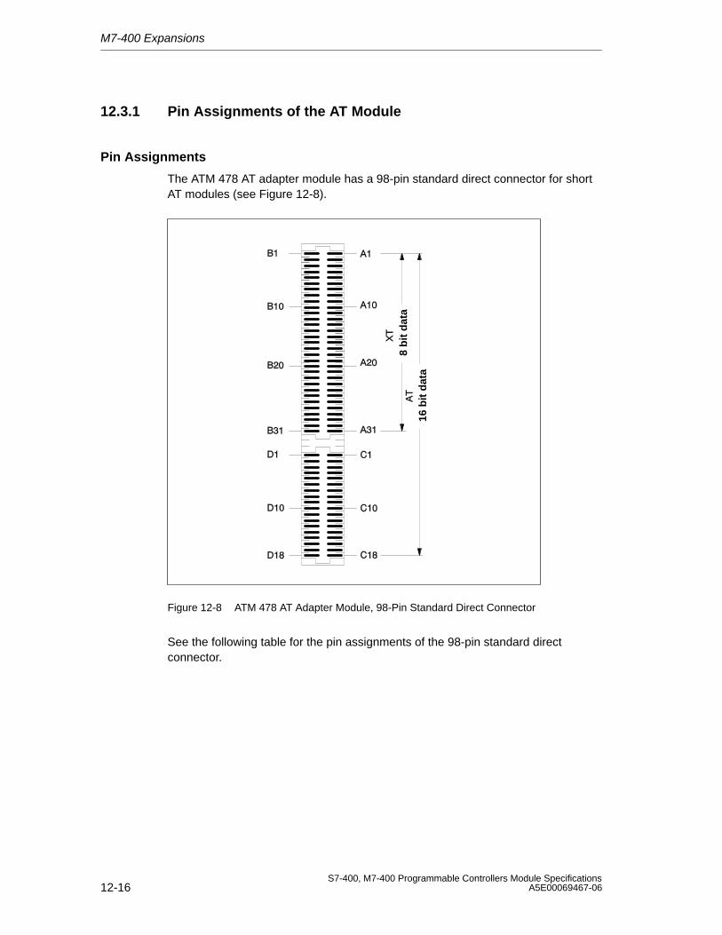
M7-400 Expansions
12-16S7-400, M7-400 Programmable Controllers Module Specifications
A5E00069467-06
12.3.1 Pin Assignments of the AT Module
Pin Assignments
The ATM 478 AT adapter module has a 98-pin standard direct connector for shortAT modules (see Figure 12-8).
16 b
it d
ata
8 b
it d
ata
Figure 12-8 ATM 478 AT Adapter Module, 98-Pin Standard Direct Connector
See the following table for the pin assignments of the 98-pin standard directconnector.

M7-400 Expansions
12-17S7-400, M7-400 Programmable Controllers Module SpecificationsA5E00069467-06
Table 12-5 Pin Assignments of the 98-Pin Standard Direct Connector(ATConnector)
Pin Signal Name Pin Signal Name
XT Signals
B1 GND A1 I/OCHCK_N
B2 RESET DRV A2 SD7
B3 P5V A3 SD6
B4 IRQ9 A4 SD5
B5 N5V A5 SD4
B6 DRQ2 A6 SD3
B7 N12V A7 SD2
B8 0WS A8 SD1
B9 P12V A9 SD0
B10 GND A10 I/OCHRDY_N
B11 SMEMW_N A11 AEN
B12 SMEMR_N A12 SA19
B13 I/OW_N A13 SA18
B14 I/OR_N A14 SA17
B15 DACK3_N A15 SA16
B16 DRQ3 A16 SA15
B17 DACK1_N A17 SA14
B18 DRQ1 A18 SA13
B19 REFRESH A19 SA12
B20 SYSCLK A20 SA11
B21 IRQ7 A21 SA10
B22 IRQ6 A22 SA9
B23 IRQ5 A23 SA8
B24 IRQ4 A24 SA7
B25 IRQ3 A25 SA6
B26 DACK2_N A26 SA5
B27 T/C A27 SA4
B28 BALE A28 SA3
B29 P5V A29 SA2
B30 OSC A30 SA1
B31 GND A31 SA0
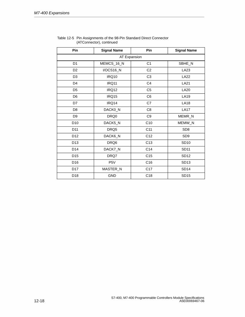
M7-400 Expansions
12-18S7-400, M7-400 Programmable Controllers Module Specifications
A5E00069467-06
Table 12-5 Pin Assignments of the 98-Pin Standard Direct Connector(ATConnector), continued
Pin Signal NamePinSignal Name
AT Expansion
D1 MEMCS_16_N C1 SBHE_N
D2 I/OCS16_N C2 LA23
D3 IRQ10 C3 LA22
D4 IRQ11 C4 LA21
D5 IRQ12 C5 LA20
D6 IRQ15 C6 LA19
D7 IRQ14 C7 LA18
D8 DACK0_N C8 LA17
D9 DRQ0 C9 MEMR_N
D10 DACK5_N C10 MEMW_N
D11 DRQ5 C11 SD8
D12 DACK6_N C12 SD9
D13 DRQ6 C13 SD10
D14 DACK7_N C14 SD11
D15 DRQ7 C15 SD12
D16 P5V C16 SD13
D17 MASTER_N C17 SD14
D18 GND C18 SD15
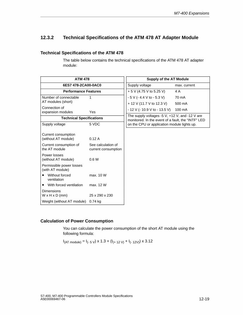
M7-400 Expansions
12-19S7-400, M7-400 Programmable Controllers Module SpecificationsA5E00069467-06
12.3.2 Technical Specifications of the ATM 478 AT Adapter Module
Technical Specifications of the ATM 478
The table below contains the technical specifications of the ATM 478 AT adaptermodule:
ATM 478
6ES7 478-2CA00-0AC0
Performance Features
Number of connectableAT modules (short)
1
Connection ofexpansion modules Yes
Technical Specifications
Supply voltage 5 VDC
Current consumption(without AT module) 0.12 A
Current consumption ofthe AT module
See calculation ofcurrent consumption
Power losses(without AT module) 0.6 W
Permissible power losses(with AT module)
• Without forcedventilation
• With forced ventilation
max. 10 W
max. 12 W
DimensionsW x H x D (mm) 25 x 290 x 230
Weight (without AT module) 0.74 kg
Supply of the AT Module
Supply voltage max. current
+ 5 V (4.75 V to 5.25 V) 4 A
- 5 V (- 4.4 V to - 5.3 V) 70 mA
+ 12 V (11.7 V to 12.3 V) 500 mA
- 12 V (- 10.9 V to - 13.5 V) 100 mA
The supply voltages -5 V, +12 V, and -12 V aremonitored. In the event of a fault, the “INTF” LEDon the CPU or application module lights up.
Calculation of Power Consumption
You can calculate the power consumption of the short AT module using thefollowing formula:
I(AT module) = I(- 5 V) x 1.3 + (I(+ 12 V) + I(- 12V)) x 3.12
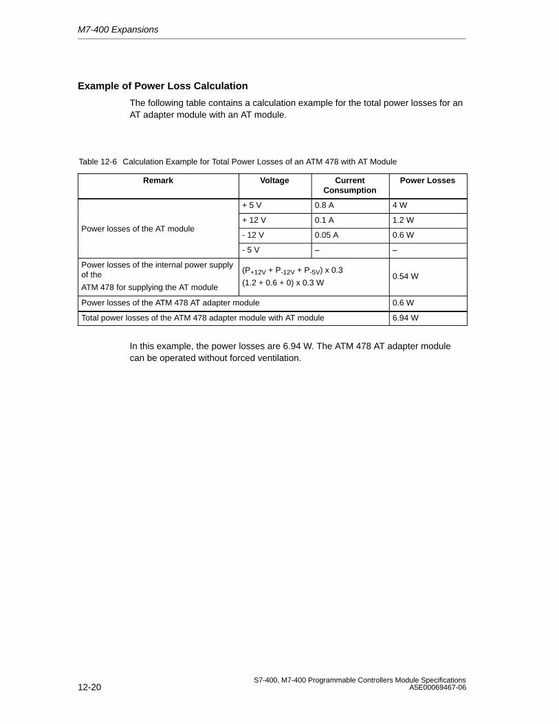
M7-400 Expansions
12-20S7-400, M7-400 Programmable Controllers Module Specifications
A5E00069467-06
Example of Power Loss Calculation
The following table contains a calculation example for the total power losses for anAT adapter module with an AT module.
Table 12-6 Calculation Example for Total Power Losses of an ATM 478 with AT Module
Remark Voltage CurrentConsumption
Power Losses
+ 5 V 0.8 A 4 W
+ 12 V 0.1 A 1.2 WPower losses of the AT module
- 12 V 0.05 A 0.6 W
- 5 V – –
Power losses of the internal power supplyof the
ATM 478 for supplying the AT module
(P+12V + P-12V + P-5V) x 0.3
(1.2 + 0.6 + 0) x 0.3 W0.54 W
Power losses of the ATM 478 AT adapter module 0.6 W
Total power losses of the ATM 478 adapter module with AT module 6.94 W
In this example, the power losses are 6.94 W. The ATM 478 AT adapter modulecan be operated without forced ventilation.
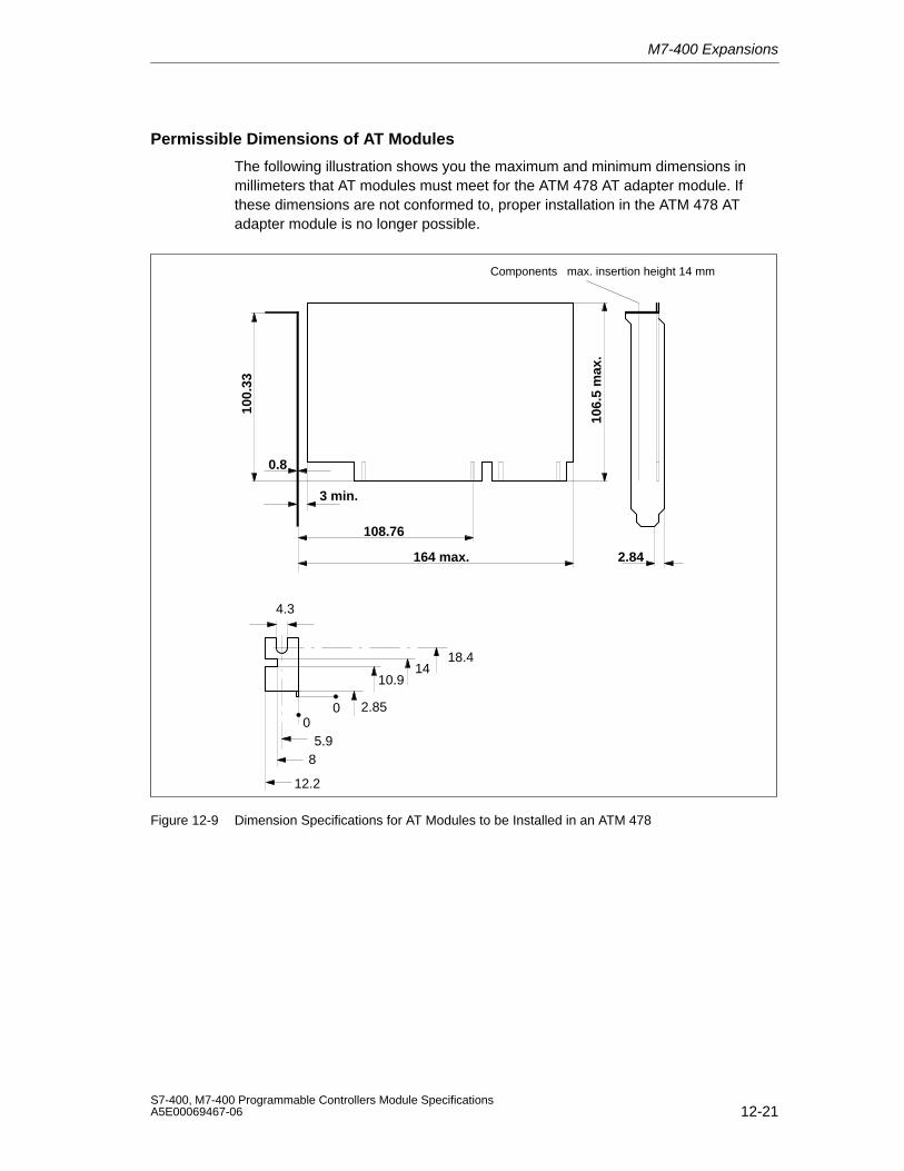
M7-400 Expansions
12-21S7-400, M7-400 Programmable Controllers Module SpecificationsA5E00069467-06
Permissible Dimensions of AT Modules
The following illustration shows you the maximum and minimum dimensions inmillimeters that AT modules must meet for the ATM 478 AT adapter module. Ifthese dimensions are not conformed to, proper installation in the ATM 478 ATadapter module is no longer possible.
Components max. insertion height 14 mm
0 2.85
10.914
18.4
05.9
8
12.2
4.3
100.
33
106.
5 m
ax.
2.84
108.76
0.8
3 min.
164 max.
Figure 12-9 Dimension Specifications for AT Modules to be Installed in an ATM 478
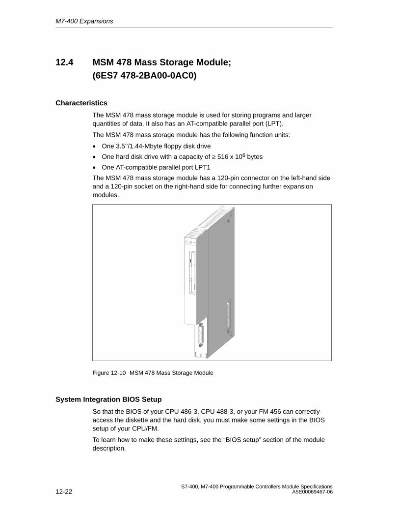
M7-400 Expansions
12-22S7-400, M7-400 Programmable Controllers Module Specifications
A5E00069467-06
12.4 MSM 478 Mass Storage Module;(6ES7 478-2BA00-0AC0)
Characteristics
The MSM 478 mass storage module is used for storing programs and largerquantities of data. It also has an AT-compatible parallel port (LPT).
The MSM 478 mass storage module has the following function units:
• One 3.5’’/1.44-Mbyte floppy disk drive
• One hard disk drive with a capacity of ≥ 516 x 106 bytes
• One AT-compatible parallel port LPT1
The MSM 478 mass storage module has a 120-pin connector on the left-hand sideand a 120-pin socket on the right-hand side for connecting further expansionmodules.
Figure 12-10 MSM 478 Mass Storage Module
System Integration BIOS Setup
So that the BIOS of your CPU 486-3, CPU 488-3, or your FM 456 can correctlyaccess the diskette and the hard disk, you must make some settings in the BIOSsetup of your CPU/FM.
To learn how to make these settings, see the “BIOS setup” section of the moduledescription.
M7-400 Expansions
12-23S7-400, M7-400 Programmable Controllers Module SpecificationsA5E00069467-06
12.4.1 LPT1 Parallel Port
Characteristics
The MSM 478 mass storage module has an AT-compatible parallel port (LPT) forconnecting a printer with Centronics interface. The parallel port can also be usedas a bi-directional data interface. There is a 25-pin sub D socket connector on thefrontside of the submodule for plugging in the connecting cable.
This parallel port is always configured by the BIOS as LPT1 regardless of the slotoccupied by the MSM 478 mass storage module.
Addressing
I/O address of the parallel port (LPT): 03BCH (to 03BEH )
Device name: LPT1
Interrupt Request
The parallel port (LPT) supplies the interrupt request IRQ7.
Pin Assignment of the Parallel Port
There is a 25-pin sub D socket connector on the frontside of the submodule forplugging in the connecting cable. See Table 12-7 for the pin assignments.
Cable Length
The cable length on the LPT1 parallel port should not exceed approximately 3 m.
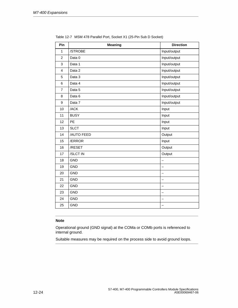
M7-400 Expansions
12-24S7-400, M7-400 Programmable Controllers Module Specifications
A5E00069467-06
Table 12-7 MSM 478 Parallel Port, Socket X1 (25-Pin Sub D Socket)
Pin Meaning Direction
1 /STROBE Input/output
2 Data 0 Input/output
3 Data 1 Input/output
4 Data 2 Input/output
5 Data 3 Input/output
6 Data 4 Input/output
7 Data 5 Input/output
8 Data 6 Input/output
9 Data 7 Input/output
10 /ACK Input
11 BUSY Input
12 PE Input
13 SLCT Input
14 /AUTO FEED Output
15 /ERROR Input
16 /RESET Output
17 /SLCT IN Output
18 GND –
19 GND –
20 GND –
21 GND –
22 GND –
23 GND –
24 GND –
25 GND –
Note
Operational ground (GND signal) at the COMa or COMb ports is referenced tointernal ground.
Suitable measures may be required on the process side to avoid ground loops.
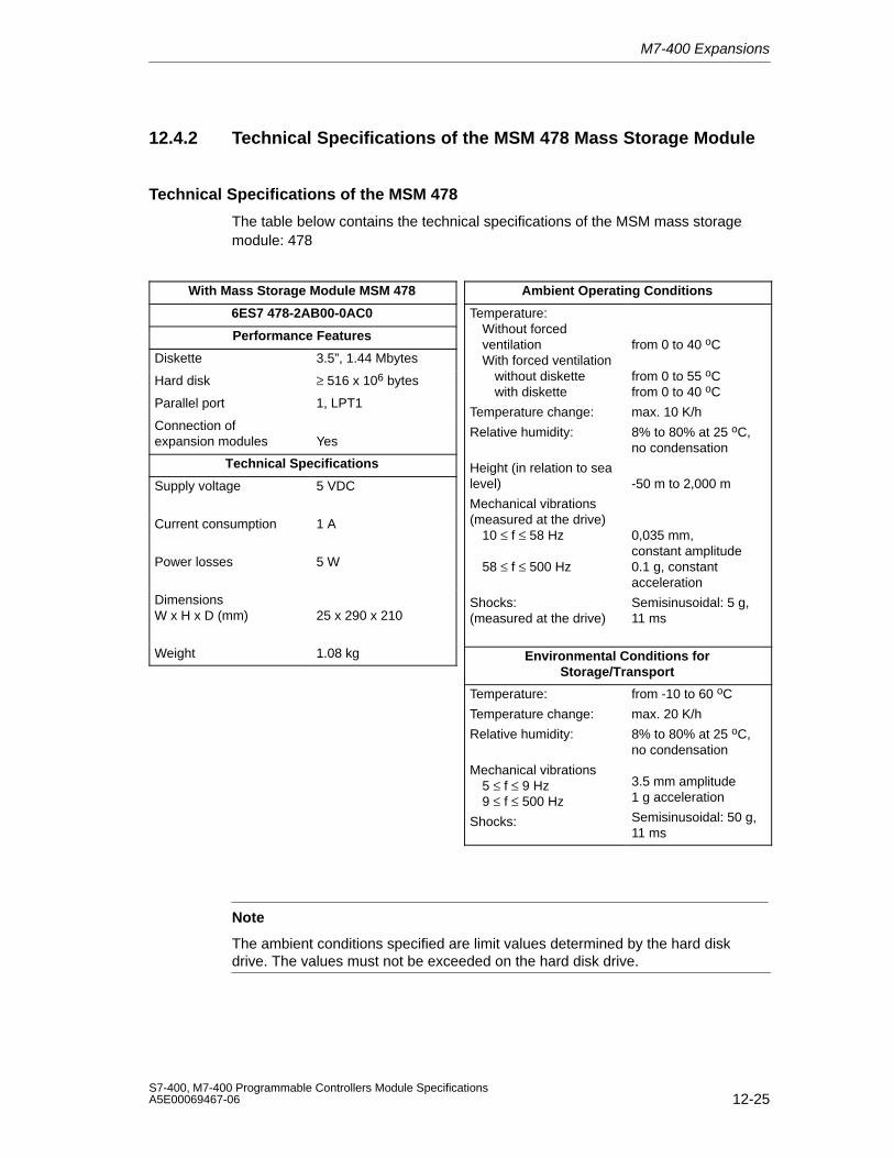
M7-400 Expansions
12-25S7-400, M7-400 Programmable Controllers Module SpecificationsA5E00069467-06
12.4.2 Technical Specifications of the MSM 478 Mass Storage Module
Technical Specifications of the MSM 478
The table below contains the technical specifications of the MSM mass storagemodule: 478
With Mass Storage Module MSM 478
6ES7 478-2AB00-0AC0
Performance Features
Diskette 3.5”, 1.44 Mbytes
Hard disk ≥ 516 x 106 bytes
Parallel port 1, LPT1
Connection ofexpansion modules Yes
Technical Specifications
Supply voltage 5 VDC
Current consumption 1 A
Power losses 5 W
DimensionsW x H x D (mm) 25 x 290 x 210
Weight 1.08 kg
Ambient Operating Conditions
Temperature:Without forced ventilationWith forced ventilation
without diskettewith diskette
Temperature change:
Relative humidity:
Height (in relation to sealevel)
Mechanical vibrations(measured at the drive)
10 ≤ f ≤ 58 Hz
58 ≤ f ≤ 500 Hz
Shocks:(measured at the drive)
from 0 to 40 oC
from 0 to 55 oCfrom 0 to 40 oC
max. 10 K/h
8% to 80% at 25 oC,no condensation
-50 m to 2,000 m
0,035 mm, constant amplitude0.1 g, constantacceleration
Semisinusoidal: 5 g,11 ms
Environmental Conditions forStorage/Transport
Temperature:
Temperature change:
Relative humidity:
Mechanical vibrations5 ≤ f ≤ 9 Hz9 ≤ f ≤ 500 Hz
Shocks:
from -10 to 60 oC
max. 20 K/h
8% to 80% at 25 oC,no condensation
3.5 mm amplitude1 g acceleration
Semisinusoidal: 50 g,11 ms
Note
The ambient conditions specified are limit values determined by the hard diskdrive. The values must not be exceeded on the hard disk drive.

M7-400 Expansions
12-26S7-400, M7-400 Programmable Controllers Module Specifications
A5E00069467-06
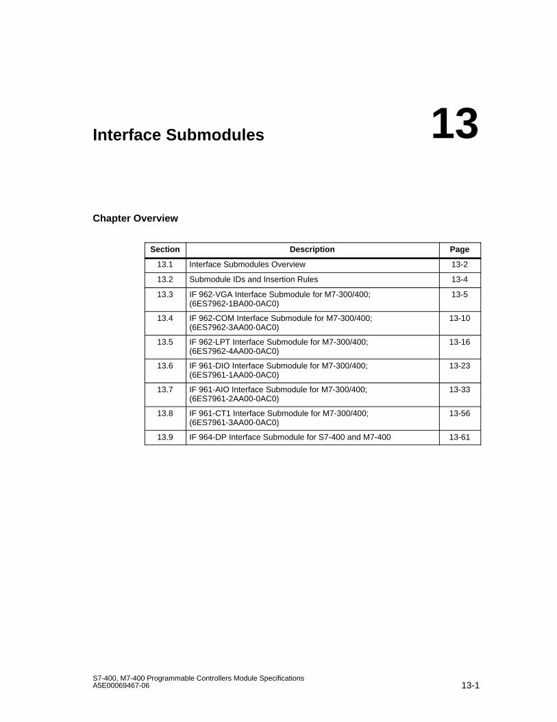
13-1S7-400, M7-400 Programmable Controllers Module SpecificationsA5E00069467-06
Interface Submodules
Chapter Overview
Section Description Page
13.1 Interface Submodules Overview 13-2
13.2 Submodule IDs and Insertion Rules 13-4
13.3 IF 962-VGA Interface Submodule for M7-300/400;(6ES7962-1BA00-0AC0)
13-5
13.4 IF 962-COM Interface Submodule for M7-300/400;(6ES7962-3AA00-0AC0)
13-10
13.5 IF 962-LPT Interface Submodule for M7-300/400;(6ES7962-4AA00-0AC0)
13-16
13.6 IF 961-DIO Interface Submodule for M7-300/400;(6ES7961-1AA00-0AC0)
13-23
13.7 IF 961-AIO Interface Submodule for M7-300/400;(6ES7961-2AA00-0AC0)
13-33
13.8 IF 961-CT1 Interface Submodule for M7-300/400;(6ES7961-3AA00-0AC0)
13-56
13.9 IF 964-DP Interface Submodule for S7-400 and M7-400 13-61
13
Interface Submodules
13-2S7-400, M7-400 Programmable Controllers Module Specifications
A5E00069467-06
13.1 Interface Submodules Overview
Introduction
The interface submodules are designed for use in the M7-300 and M7-400automation computers. They can be operated in the M7-400 programmablemodules and in the EXM 378/EXM 478 expansion modules. The interfacesubmodules are controlled via the ISA bus.
The interface submodules are labeled on the front plate and so can be identifiedeven when installed.
Handling
Interface submodules and their front connectors must only be plugged in orremoved when the power is switched off. Avoid confusing front connectors sincethis can destroy the interface submodules or the connected devices.
ESD Guidelines
The interface submodules are not enclosed on the underside. For this reason, youmust observe ESD guidelines when handling these modules.
Slots/Submodule Receptacle Numbers
To link the interface submodules into your system (for example, BIOS Setup), yourequire the submodule receptacle numbers. See the descriptions of the M7-400programmable modules or the M7-300/400 expansion modules for the numberingof the individual submodule receptacles.
Addressing in the M7-300/400 - Reserved I/O Address Area
In the M7-300/400 automation computers, the I/O address area C000H is reservedfor addressing the interface submodules.
The base address at which an interface submodule can be addressed depends onthe submodule receptacle of the M7-400 programmable module or the M7-300/400expansion module containing the interface submodule. You can find thesubmodule-receptacle-dependent base address of the interface submodule in thedescription of the M7-400 programmable module or the M7-300/400 expansionmodule.
The sections below describe the registers and their meanings as well as theassociated offset addresses for the individual interface submodules.
The resulting I/O address is the sum of the base address and the offset address.
Submodule ID
Each interface submodule has a submodule ID stored in read-only memory. Thisinformation is required in the BIOS Setup.
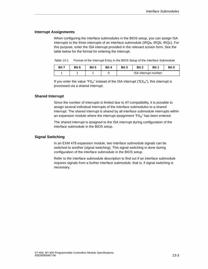
Interface Submodules
13-3S7-400, M7-400 Programmable Controllers Module SpecificationsA5E00069467-06
Interrupt Assignments
When configuring the interface submodules in the BIOS setup, you can assign ISAinterrupts to the three interrupts of an interface submodule (IRQa, IRQb, IRQc). Forthis purpose, enter the ISA interrupt provided in the relevant screen form. See thetable below for the format for entering the interrupt.
Table 13-1 Format of the Interrupt Entry in the BIOS Setup of the Interface Submodule
Bit 7 Bit 6 Bit 5 Bit 4 Bit 3 Bit 2 Bit 1 Bit 0
1 1 1 0 ISA interrupt number
If you enter the value “F0H” instead of the ISA interrupt (“EXH”), this interrupt isprocessed via a shared interrupt.
Shared Interrupt
Since the number of interrupts is limited due to AT-compatibility, it is possible toassign several individual interrupts of the interface submodules to a sharedinterrupt. The shared interrupt is shared by all interface submodule interrupts withinan expansion module where the interrupt assignment “F0H” has been entered.
The shared interrupt is assigned to the ISA interrupt during configuration of theinterface submodule in the BIOS setup.
Signal Switching
In an EXM 478 expansion module, two interface submodule signals can beswitched to another (signal switching). This signal switching is done duringconfiguration of the interface submodule in the BIOS setup.
Refer to the interface submodule description to find out if an interface submodulerequires signals from a further interface submodule, that is, if signal switching isnecessary.
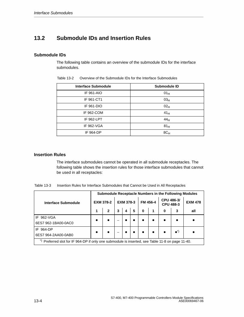
Interface Submodules
13-4S7-400, M7-400 Programmable Controllers Module Specifications
A5E00069467-06
13.2 Submodule IDs and Insertion Rules
Submodule IDs
The following table contains an overview of the submodule IDs for the interfacesubmodules.
Table 13-2 Overview of the Submodule IDs for the Interface Submodules
Interface Submodule Submodule ID
IF 961-AIO 01H
IF 961-CT1 03H
IF 961-DIO 02H
IF 962-COM 41H
IF 962-LPT 44H
IF 962-VGA 81H
IF 964-DP 8CH
Insertion Rules
The interface submodules cannot be operated in all submodule receptacles. Thefollowing table shows the insertion rules for those interface submodules that cannotbe used in all receptacles:
Table 13-3 Insertion Rules for Interface Submodules that Cannot be Used in All Receptacles
Submodule Receptacle Numbers in the Following Modules
Interface Submodule EXM 378-2 EXM 378-3 FM 456-4 CPU 486-3/CPU 488-3
EXM 478
1 2 3 4 5 0 1 0 3 all
IF 962-VGA
6ES7 962-1BA00-0AC0 –
IF 964-DP
6ES7 964-2AA00-0AB0 – *)
*) Preferred slot for IF 964-DP if only one submodule is inserted, see Table 11-8 on page 11-40.
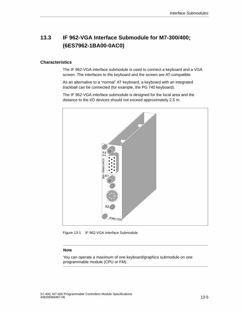
Interface Submodules
13-5S7-400, M7-400 Programmable Controllers Module SpecificationsA5E00069467-06
13.3 IF 962-VGA Interface Submodule for M7-300/400;(6ES7962-1BA00-0AC0)
Characteristics
The IF 962-VGA interface submodule is used to connect a keyboard and a VGAscreen. The interfaces to the keyboard and the screen are AT-compatible.
As an alternative to a “normal” AT keyboard, a keyboard with an integratedtrackball can be connected (for example, the PG 740 keyboard).
The IF 962-VGA interface submodule is designed for the local area and thedistance to the I/O devices should not exceed approximately 2.5 m.
Figure 13-1 IF 962-VGA Interface Submodule
Note
You can operate a maximum of one keyboard/graphics submodule on oneprogrammable module (CPU or FM).
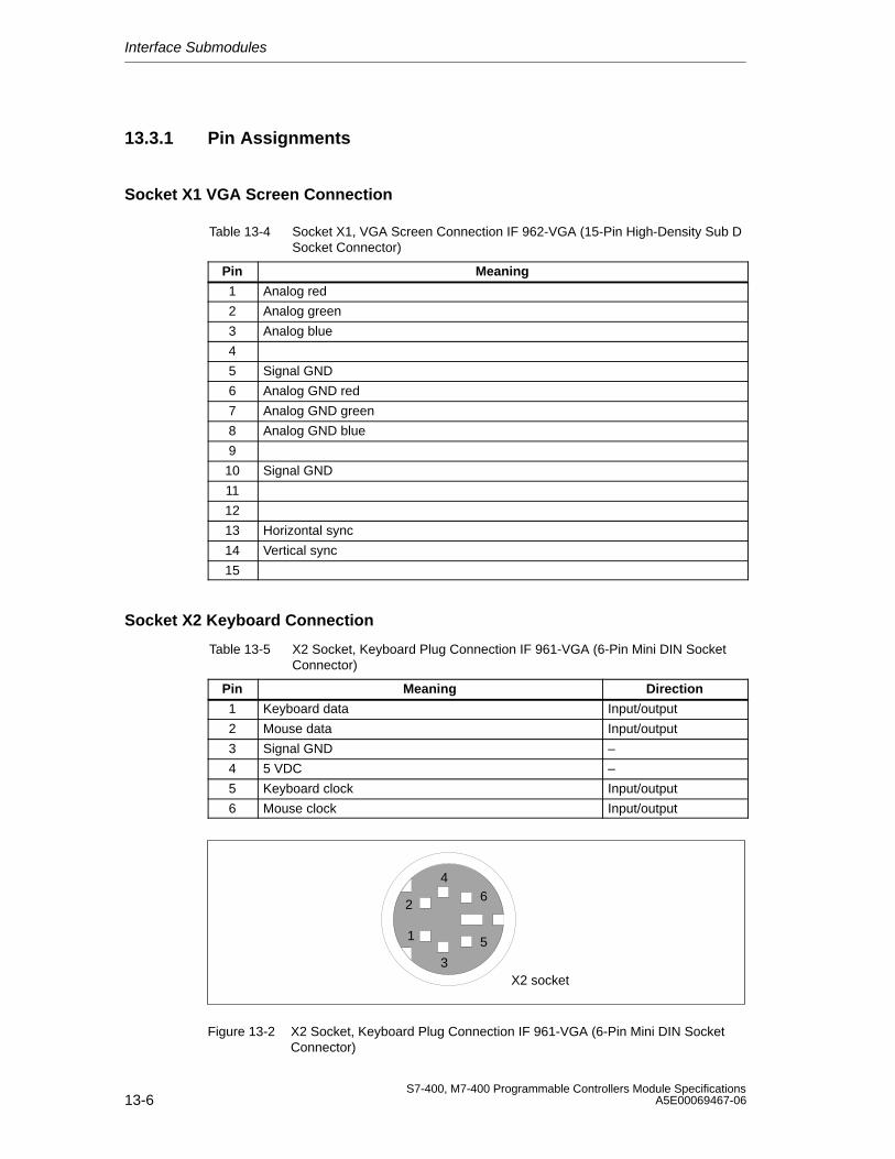
Interface Submodules
13-6S7-400, M7-400 Programmable Controllers Module Specifications
A5E00069467-06
13.3.1 Pin Assignments
Socket X1 VGA Screen Connection
Table 13-4 Socket X1, VGA Screen Connection IF 962-VGA (15-Pin High-Density Sub DSocket Connector)
Pin Meaning
1 Analog red
2 Analog green
3 Analog blue
4
5 Signal GND
6 Analog GND red
7 Analog GND green
8 Analog GND blue
9
10 Signal GND
11
12
13 Horizontal sync
14 Vertical sync
15
Socket X2 Keyboard Connection
Table 13-5 X2 Socket, Keyboard Plug Connection IF 961-VGA (6-Pin Mini DIN SocketConnector)
Pin Meaning Direction
1 Keyboard data Input/output
2 Mouse data Input/output
3 Signal GND –
4 5 VDC –
5 Keyboard clock Input/output
6 Mouse clock Input/output
1
2
3
4
5
6
X2 socket
Figure 13-2 X2 Socket, Keyboard Plug Connection IF 961-VGA (6-Pin Mini DIN SocketConnector)
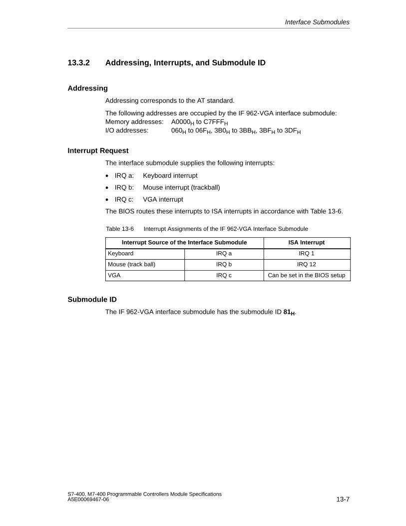
Interface Submodules
13-7S7-400, M7-400 Programmable Controllers Module SpecificationsA5E00069467-06
13.3.2 Addressing, Interrupts, and Submodule ID
Addressing
Addressing corresponds to the AT standard.
The following addresses are occupied by the IF 962-VGA interface submodule:Memory addresses: A0000H to C7FFFHI/O addresses: 060H to 06FH, 3B0H to 3BBH, 3BFH to 3DFH
Interrupt Request
The interface submodule supplies the following interrupts:
• IRQ a: Keyboard interrupt
• IRQ b: Mouse interrupt (trackball)
• IRQ c: VGA interrupt
The BIOS routes these interrupts to ISA interrupts in accordance with Table 13-6.
Table 13-6 Interrupt Assignments of the IF 962-VGA Interface Submodule
Interrupt Source of the Interface Submodule ISA Interrupt
Keyboard IRQ a IRQ 1
Mouse (track ball) IRQ b IRQ 12
VGA IRQ c Can be set in the BIOS setup
Submodule ID
The IF 962-VGA interface submodule has the submodule ID 81H.
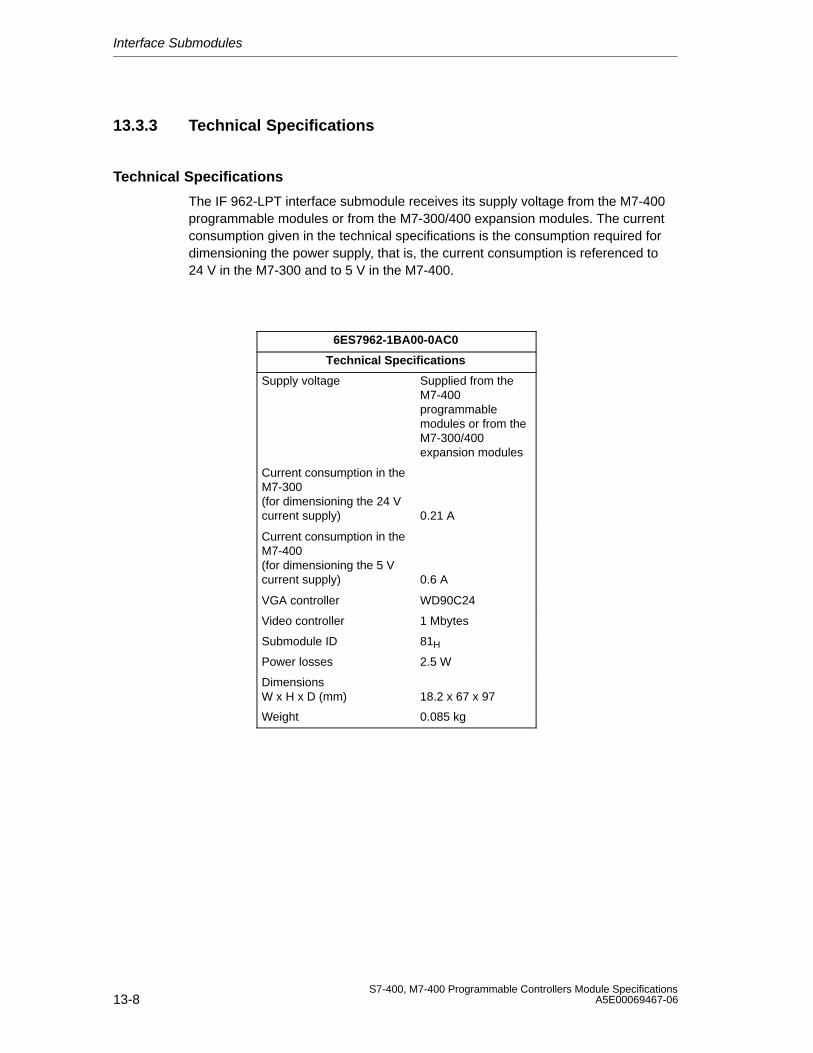
Interface Submodules
13-8S7-400, M7-400 Programmable Controllers Module Specifications
A5E00069467-06
13.3.3 Technical Specifications
Technical Specifications
The IF 962-LPT interface submodule receives its supply voltage from the M7-400programmable modules or from the M7-300/400 expansion modules. The currentconsumption given in the technical specifications is the consumption required fordimensioning the power supply, that is, the current consumption is referenced to24 V in the M7-300 and to 5 V in the M7-400.
6ES7962-1BA00-0AC0
Technical Specifications
Supply voltage Supplied from theM7-400programmablemodules or from theM7-300/400expansion modules
Current consumption in theM7-300 (for dimensioning the 24 Vcurrent supply) 0.21 A
Current consumption in theM7-400 (for dimensioning the 5 Vcurrent supply) 0.6 A
VGA controller WD90C24
Video controller 1 Mbytes
Submodule ID 81H
Power losses 2.5 W
DimensionsW x H x D (mm) 18.2 x 67 x 97
Weight 0.085 kg
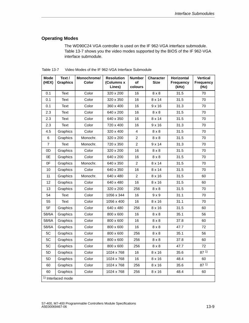
Interface Submodules
13-9S7-400, M7-400 Programmable Controllers Module SpecificationsA5E00069467-06
Operating Modes
The WD90C24 VGA controller is used on the IF 962-VGA interface submodule.Table 13-7 shows you the video modes supported by the BIOS of the IF 962-VGAinterface submodule.
Table 13-7 Video Modes of the IF 962-VGA Interface Submodule
Mode(HEX)
Text /Graphics
Monochrome/Color
Resolution(Columns x
Lines)
Numberof
colours
CharacterSize
HorizontalFrequency
(kHz)
VerticalFrequency
(Hz)
0.1 Text Color 320 x 200 16 8 x 8 31.5 70
0.1 Text Color 320 x 350 16 8 x 14 31.5 70
0.1 Text Color 360 x 400 16 9 x 16 31.3 70
2.3 Text Color 640 x 200 16 8 x 8 31.5 70
2.3 Text Color 640 x 350 16 8 x 14 31.5 70
2.3 Text Color 720 x 400 16 9 x 16 31.3 70
4.5 Graphics Color 320 x 400 4 8 x 8 31.5 70
6 Graphics Monochr. 320 x 200 2 8 x 8 31.5 70
7 Text Monochr. 720 x 350 2 9 x 14 31.3 70
0D Graphics Color 320 x 200 16 8 x 8 31.5 70
0E Graphics Color 640 x 200 16 8 x 8 31.5 70
0F Graphics Monochr. 640 x 350 2 8 x 14 31.5 70
10 Graphics Color 640 x 350 16 8 x 14 31.5 70
11 Graphics Monochr. 640 x 480 2 8 x 16 31.5 60
12 Graphics Color 640 x 480 16 8 x 16 31.5 60
13 Graphics Color 320 x 200 256 8 x 8 31.5 70
54 Text Color 1056 x 344 16 9 x 9 31.1 70
55 Text Color 1056 x 400 16 8 x 16 31.1 70
5F Graphics Color 640 x 480 256 8 x 16 31.5 60
58/6A Graphics Color 800 x 600 16 8 x 8 35.1 56
58/6A Graphics Color 800 x 600 16 8 x 8 37.8 60
58/6A Graphics Color 800 x 600 16 8 x 8 47.7 72
5C Graphics Color 800 x 600 256 8 x 8 35.1 56
5C Graphics Color 800 x 600 256 8 x 8 37.8 60
5C Graphics Color 800 x 600 256 8 x 8 47.7 72
5D Graphics Color 1024 x 768 16 8 x 16 35.6 87 1)
5D Graphics Color 1024 x 768 16 8 x 16 48.4 60
60 Graphics Color 1024 x 768 256 8 x 16 35.6 87 1)
60 Graphics Color 1024 x 768 256 8 x 16 48.4 60
1) Interlaced mode
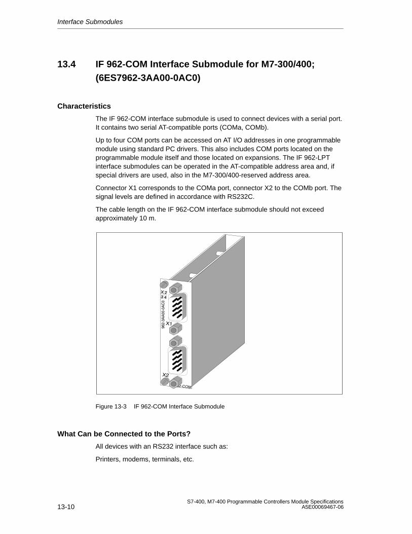
Interface Submodules
13-10S7-400, M7-400 Programmable Controllers Module Specifications
A5E00069467-06
13.4 IF 962-COM Interface Submodule for M7-300/400;(6ES7962-3AA00-0AC0)
Characteristics
The IF 962-COM interface submodule is used to connect devices with a serial port.It contains two serial AT-compatible ports (COMa, COMb).
Up to four COM ports can be accessed on AT I/O addresses in one programmablemodule using standard PC drivers. This also includes COM ports located on theprogrammable module itself and those located on expansions. The IF 962-LPTinterface submodules can be operated in the AT-compatible address area and, ifspecial drivers are used, also in the M7-300/400-reserved address area.
Connector X1 corresponds to the COMa port, connector X2 to the COMb port. Thesignal levels are defined in accordance with RS232C.
The cable length on the IF 962-COM interface submodule should not exceedapproximately 10 m.
Figure 13-3 IF 962-COM Interface Submodule
What Can be Connected to the Ports?
All devices with an RS232 interface such as:
Printers, modems, terminals, etc.
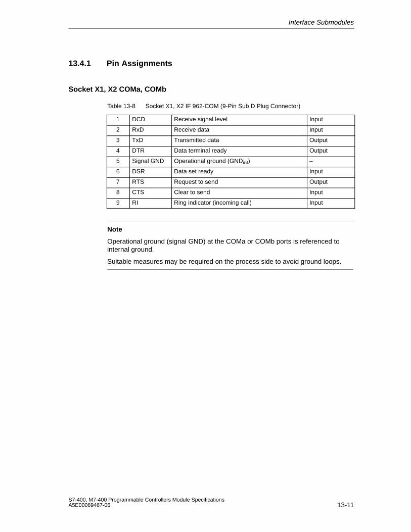
Interface Submodules
13-11S7-400, M7-400 Programmable Controllers Module SpecificationsA5E00069467-06
13.4.1 Pin Assignments
Socket X1, X2 COMa, COMb
Table 13-8 Socket X1, X2 IF 962-COM (9-Pin Sub D Plug Connector)
1 DCD Receive signal level Input
2 RxD Receive data Input
3 TxD Transmitted data Output
4 DTR Data terminal ready Output
5 Signal GND Operational ground (GNDint) –
6 DSR Data set ready Input
7 RTS Request to send Output
8 CTS Clear to send Input
9 RI Ring indicator (incoming call) Input
Note
Operational ground (signal GND) at the COMa or COMb ports is referenced tointernal ground.
Suitable measures may be required on the process side to avoid ground loops.
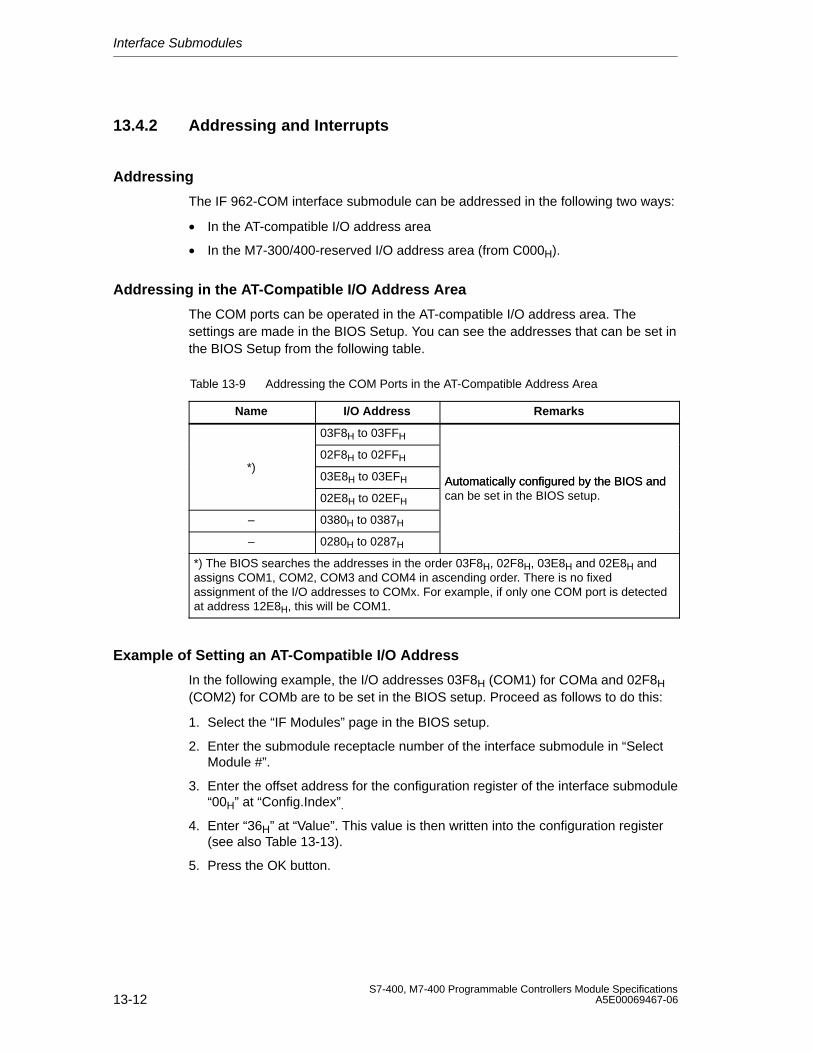
Interface Submodules
13-12S7-400, M7-400 Programmable Controllers Module Specifications
A5E00069467-06
13.4.2 Addressing and Interrupts
Addressing
The IF 962-COM interface submodule can be addressed in the following two ways:
• In the AT-compatible I/O address area
• In the M7-300/400-reserved I/O address area (from C000H).
Addressing in the AT-Compatible I/O Address Area
The COM ports can be operated in the AT-compatible I/O address area. Thesettings are made in the BIOS Setup. You can see the addresses that can be set inthe BIOS Setup from the following table.
Table 13-9 Addressing the COM Ports in the AT-Compatible Address Area
Name I/O Address Remarks
03F8H to 03FFH
02F8H to 02FFH*)
03E8H to 03EFH Automatically configured by the BIOS and02E8H to 02EFH
Automatically configured by the BIOS andcan be set in the BIOS setup.
– 0380H to 0387H
– 0280H to 0287H
*) The BIOS searches the addresses in the order 03F8H, 02F8H, 03E8H and 02E8H andassigns COM1, COM2, COM3 and COM4 in ascending order. There is no fixedassignment of the I/O addresses to COMx. For example, if only one COM port is detectedat address 12E8H, this will be COM1.
Example of Setting an AT-Compatible I/O Address
In the following example, the I/O addresses 03F8H (COM1) for COMa and 02F8H(COM2) for COMb are to be set in the BIOS setup. Proceed as follows to do this:
1. Select the “IF Modules” page in the BIOS setup.
2. Enter the submodule receptacle number of the interface submodule in “SelectModule #”.
3. Enter the offset address for the configuration register of the interface submodule“00H” at “Config.Index”.
4. Enter “36H” at “Value”. This value is then written into the configuration register(see also Table 13-13).
5. Press the OK button.
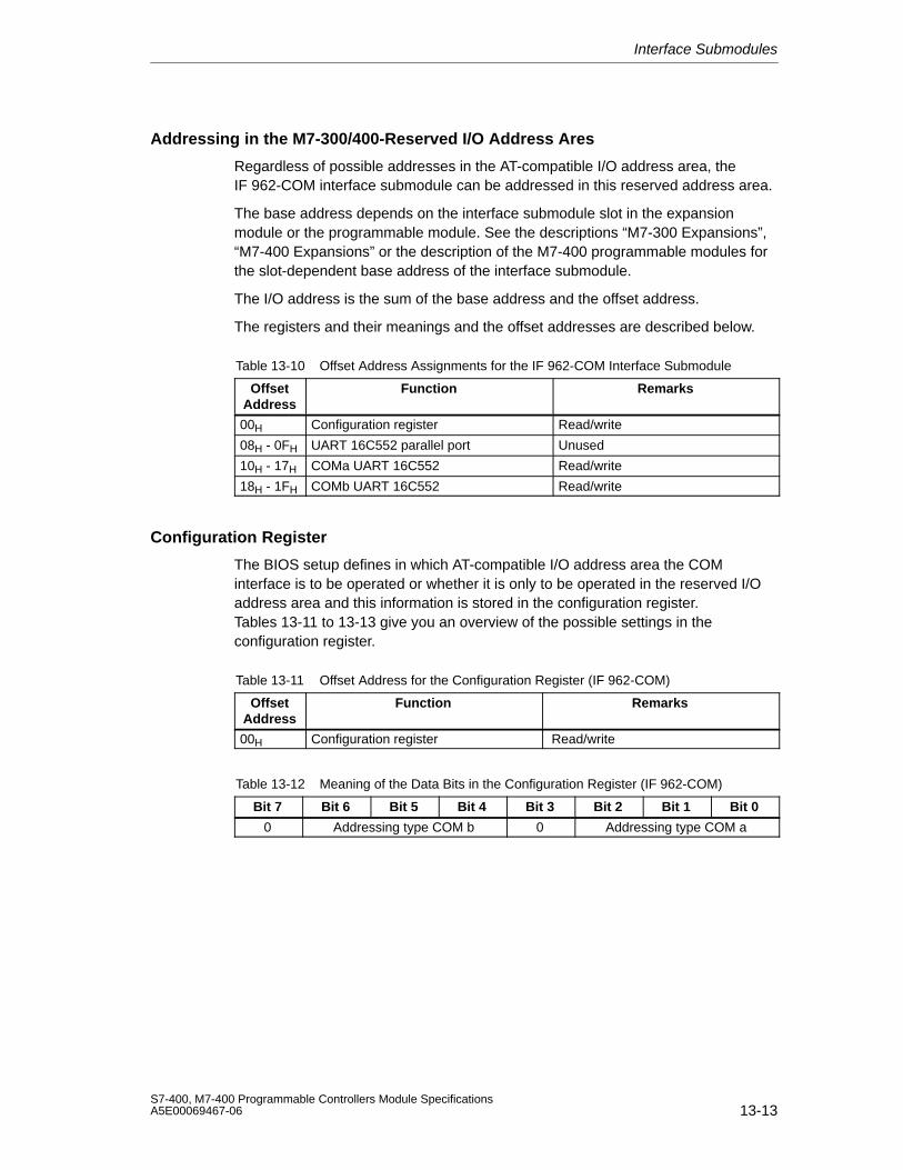
Interface Submodules
13-13S7-400, M7-400 Programmable Controllers Module SpecificationsA5E00069467-06
Addressing in the M7-300/400-Reserved I/O Address Ares
Regardless of possible addresses in the AT-compatible I/O address area, theIF 962-COM interface submodule can be addressed in this reserved address area.
The base address depends on the interface submodule slot in the expansionmodule or the programmable module. See the descriptions “M7-300 Expansions”,“M7-400 Expansions” or the description of the M7-400 programmable modules forthe slot-dependent base address of the interface submodule.
The I/O address is the sum of the base address and the offset address.
The registers and their meanings and the offset addresses are described below.
Table 13-10 Offset Address Assignments for the IF 962-COM Interface Submodule
OffsetAddress
Function Remarks
00H Configuration register Read/write
08H - 0FH UART 16C552 parallel port Unused
10H - 17H COMa UART 16C552 Read/write
18H - 1FH COMb UART 16C552 Read/write
Configuration Register
The BIOS setup defines in which AT-compatible I/O address area the COMinterface is to be operated or whether it is only to be operated in the reserved I/Oaddress area and this information is stored in the configuration register.Tables 13-11 to 13-13 give you an overview of the possible settings in theconfiguration register.
Table 13-11 Offset Address for the Configuration Register (IF 962-COM)
OffsetAddress
Function Remarks
00H Configuration register Read/write
Table 13-12 Meaning of the Data Bits in the Configuration Register (IF 962-COM)
Bit 7 Bit 6 Bit 5 Bit 4 Bit 3 Bit 2 Bit 1 Bit 0
0 Addressing type COM b 0 Addressing type COM a
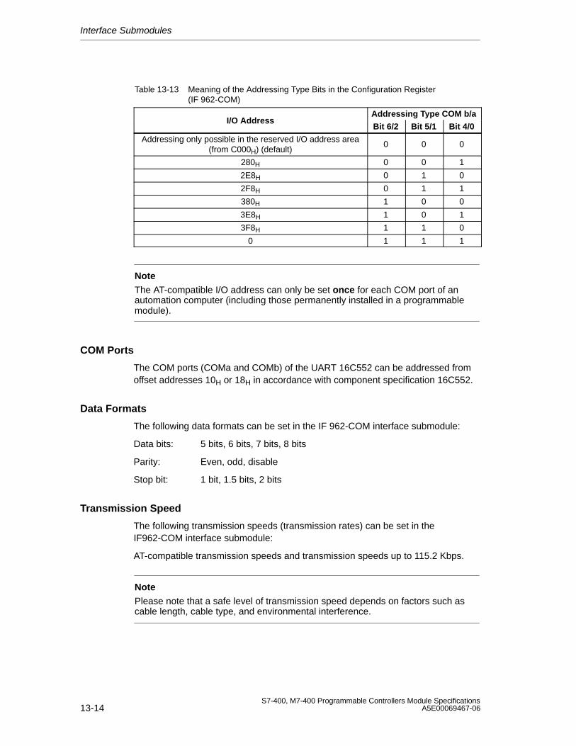
Interface Submodules
13-14S7-400, M7-400 Programmable Controllers Module Specifications
A5E00069467-06
Table 13-13 Meaning of the Addressing Type Bits in the Configuration Register(IF 962-COM)
Addressing Type COM b/aI/O Address
Bit 6/2 Bit 5/1 Bit 4/0
Addressing only possible in the reserved I/O address area(from C000H) (default)
0 0 0
280H 0 0 1
2E8H 0 1 0
2F8H 0 1 1
380H 1 0 0
3E8H 1 0 1
3F8H 1 1 0
0 1 1 1
NoteThe AT-compatible I/O address can only be set once for each COM port of anautomation computer (including those permanently installed in a programmablemodule).
COM Ports
The COM ports (COMa and COMb) of the UART 16C552 can be addressed fromoffset addresses 10H or 18H in accordance with component specification 16C552.
Data Formats
The following data formats can be set in the IF 962-COM interface submodule:
Data bits: 5 bits, 6 bits, 7 bits, 8 bits
Parity: Even, odd, disable
Stop bit: 1 bit, 1.5 bits, 2 bits
Transmission Speed
The following transmission speeds (transmission rates) can be set in theIF962-COM interface submodule:
AT-compatible transmission speeds and transmission speeds up to 115.2 Kbps.
NotePlease note that a safe level of transmission speed depends on factors such ascable length, cable type, and environmental interference.
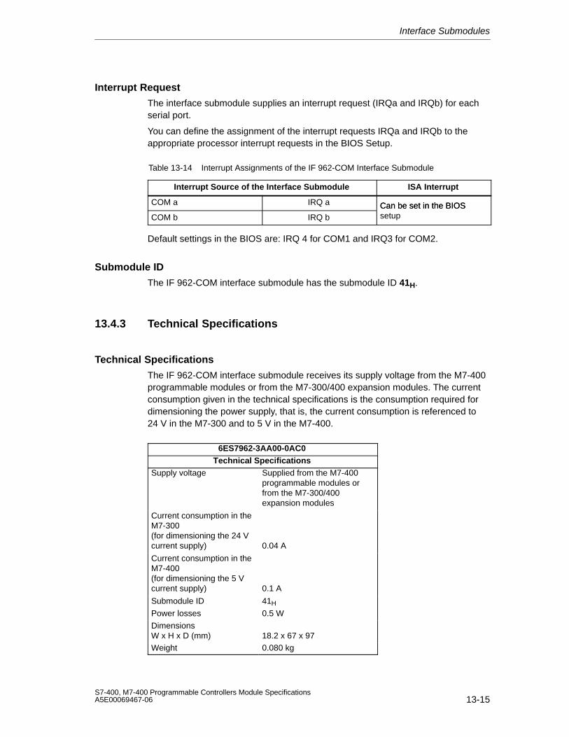
Interface Submodules
13-15S7-400, M7-400 Programmable Controllers Module SpecificationsA5E00069467-06
Interrupt Request
The interface submodule supplies an interrupt request (IRQa and IRQb) for eachserial port.
You can define the assignment of the interrupt requests IRQa and IRQb to theappropriate processor interrupt requests in the BIOS Setup.
Table 13-14 Interrupt Assignments of the IF 962-COM Interface Submodule
Interrupt Source of the Interface Submodule ISA Interrupt
COM a IRQ a Can be set in the BIOSCOM b IRQ b
Can be set in the BIOSsetup
Default settings in the BIOS are: IRQ 4 for COM1 and IRQ3 for COM2.
Submodule ID
The IF 962-COM interface submodule has the submodule ID 41H.
13.4.3 Technical Specifications
Technical Specifications
The IF 962-COM interface submodule receives its supply voltage from the M7-400programmable modules or from the M7-300/400 expansion modules. The currentconsumption given in the technical specifications is the consumption required fordimensioning the power supply, that is, the current consumption is referenced to24 V in the M7-300 and to 5 V in the M7-400.
6ES7962-3AA00-0AC0Technical Specifications
Supply voltage Supplied from the M7-400programmable modules orfrom the M7-300/400expansion modules
Current consumption in theM7-300 (for dimensioning the 24 Vcurrent supply) 0.04 A
Current consumption in theM7-400 (for dimensioning the 5 Vcurrent supply) 0.1 A
Submodule ID 41H
Power losses 0.5 W
DimensionsW x H x D (mm) 18.2 x 67 x 97
Weight 0.080 kg
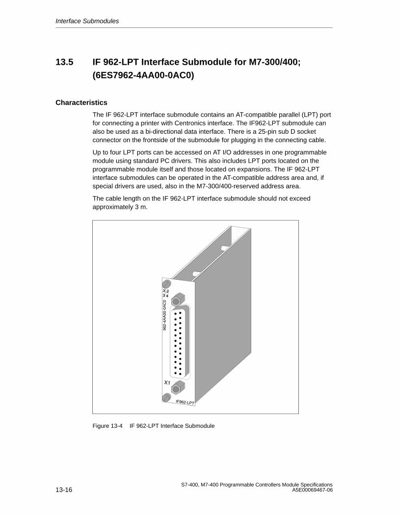
Interface Submodules
13-16S7-400, M7-400 Programmable Controllers Module Specifications
A5E00069467-06
13.5 IF 962-LPT Interface Submodule for M7-300/400;(6ES7962-4AA00-0AC0)
Characteristics
The IF 962-LPT interface submodule contains an AT-compatible parallel (LPT) portfor connecting a printer with Centronics interface. The IF962-LPT submodule canalso be used as a bi-directional data interface. There is a 25-pin sub D socketconnector on the frontside of the submodule for plugging in the connecting cable.
Up to four LPT ports can be accessed on AT I/O addresses in one programmablemodule using standard PC drivers. This also includes LPT ports located on theprogrammable module itself and those located on expansions. The IF 962-LPTinterface submodules can be operated in the AT-compatible address area and, ifspecial drivers are used, also in the M7-300/400-reserved address area.
The cable length on the IF 962-LPT interface submodule should not exceedapproximately 3 m.
Figure 13-4 IF 962-LPT Interface Submodule
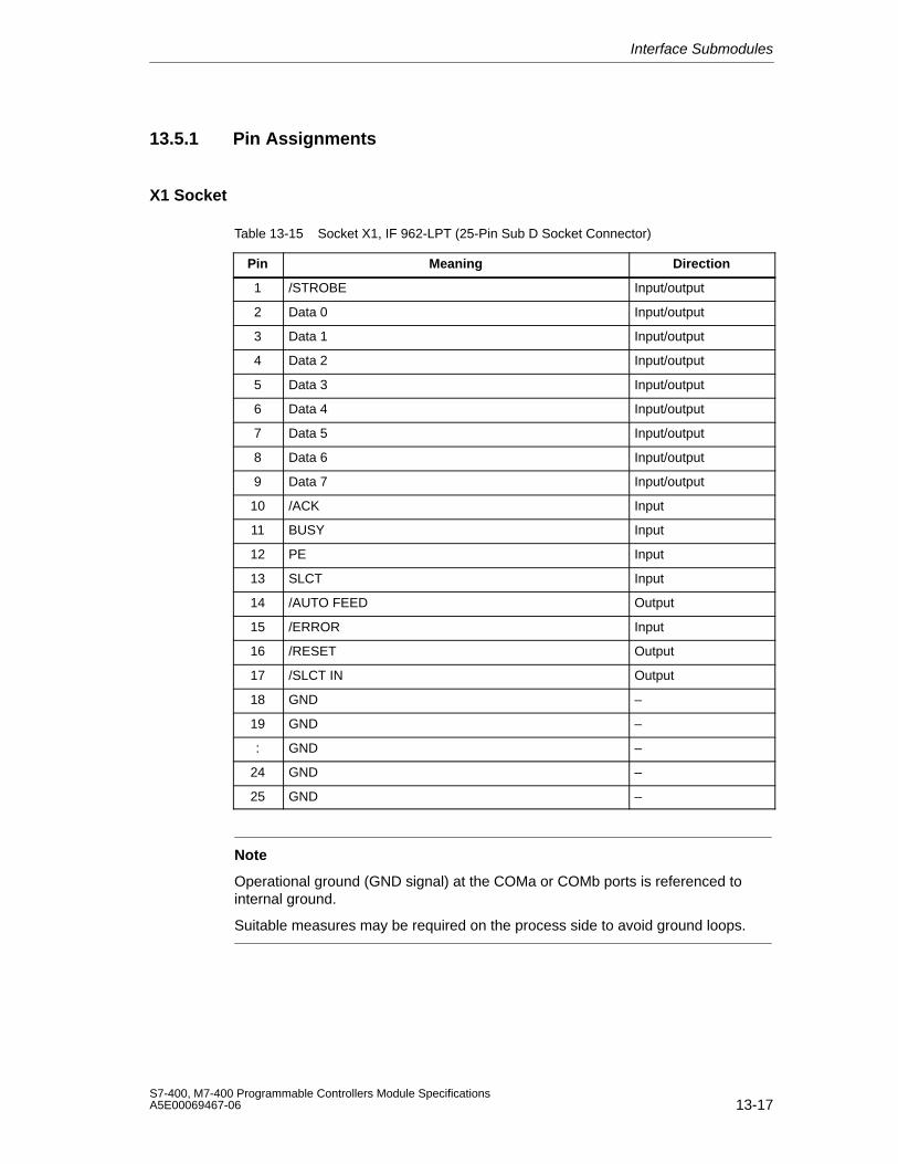
Interface Submodules
13-17S7-400, M7-400 Programmable Controllers Module SpecificationsA5E00069467-06
13.5.1 Pin Assignments
X1 Socket
Table 13-15 Socket X1, IF 962-LPT (25-Pin Sub D Socket Connector)
Pin Meaning Direction
1 /STROBE Input/output
2 Data 0 Input/output
3 Data 1 Input/output
4 Data 2 Input/output
5 Data 3 Input/output
6 Data 4 Input/output
7 Data 5 Input/output
8 Data 6 Input/output
9 Data 7 Input/output
10 /ACK Input
11 BUSY Input
12 PE Input
13 SLCT Input
14 /AUTO FEED Output
15 /ERROR Input
16 /RESET Output
17 /SLCT IN Output
18 GND –
19 GND –
: GND –
24 GND –
25 GND –
Note
Operational ground (GND signal) at the COMa or COMb ports is referenced tointernal ground.
Suitable measures may be required on the process side to avoid ground loops.
Interface Submodules
13-18S7-400, M7-400 Programmable Controllers Module Specifications
A5E00069467-06
13.5.2 Addressing and Interrupts
Addressing
The IF 962-LPT interface submodule can be addressed in the following two ways:
• In the AT-compatible I/O address area
• In the M7-300/400-reserved I/O address area (from C000H)
Addressing in the AT-Compatible I/O Address Area
The LPT ports can be operated in the AT-compatible I/O address area. Thesettings are made in the BIOS Setup. You can see the addresses that can be set inthe BIOS Setup from the following table.
Table 13-16 Addressing the LPT Ports
Name I/O Address Remarks
03BCH to 3BEH
*) 0378H to 37FHAutomatically configured by the BIOS and
0278H to 27FH
can be set in the BIOS setup.
*) The BIOS searches the addresses in the order 03BCH, 0378H and 0278H and assignsLPT1, LPT2 and LPT3 in ascending order. There is no fixed assignment of the I/Oaddresses to LPTx. For example, if only one LPT port is detected at address 0378H, thiswill be LPT1.
Note
The LPT port in the M7-400 expansion module MSM 478 is always at the I/Oaddress 03BCH. For this reason, the I/O address 03BCH must not be set for the IP962-LPT interface submodule if an MSM 478 is in use.
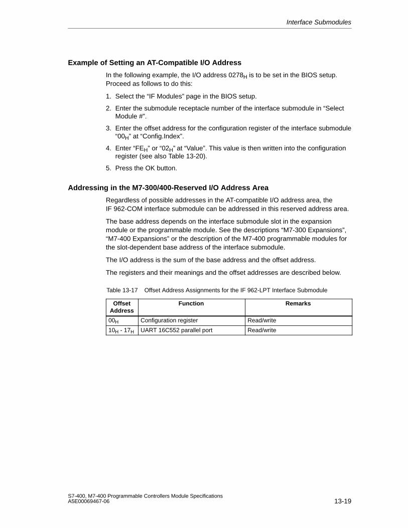
Interface Submodules
13-19S7-400, M7-400 Programmable Controllers Module SpecificationsA5E00069467-06
Example of Setting an AT-Compatible I/O Address
In the following example, the I/O address 0278H is to be set in the BIOS setup.Proceed as follows to do this:
1. Select the “IF Modules” page in the BIOS setup.
2. Enter the submodule receptacle number of the interface submodule in “SelectModule #”.
3. Enter the offset address for the configuration register of the interface submodule“00H” at “Config.Index”.
4. Enter “FEH” or “02H” at “Value”. This value is then written into the configurationregister (see also Table 13-20).
5. Press the OK button.
Addressing in the M7-300/400-Reserved I/O Address Area
Regardless of possible addresses in the AT-compatible I/O address area, theIF 962-COM interface submodule can be addressed in this reserved address area.
The base address depends on the interface submodule slot in the expansionmodule or the programmable module. See the descriptions “M7-300 Expansions”,“M7-400 Expansions” or the description of the M7-400 programmable modules forthe slot-dependent base address of the interface submodule.
The I/O address is the sum of the base address and the offset address.
The registers and their meanings and the offset addresses are described below.
Table 13-17 Offset Address Assignments for the IF 962-LPT Interface Submodule
OffsetAddress
Function Remarks
00H Configuration register Read/write
10H - 17H UART 16C552 parallel port Read/write
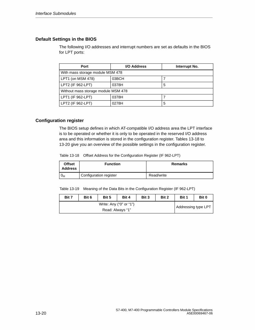
Interface Submodules
13-20S7-400, M7-400 Programmable Controllers Module Specifications
A5E00069467-06
Default Settings in the BIOS
The following I/O addresses and interrupt numbers are set as defaults in the BIOSfor LPT ports:
Port I/O Address Interrupt No.
With mass storage module MSM 478
LPT1 (on MSM 478) 03BCH 7
LPT2 (IF 962-LPT) 0378H 5
Without mass storage module MSM 478
LPT1 (IF 962-LPT) 0378H 7
LPT2 (IF 962-LPT) 0278H 5
Configuration register
The BIOS setup defines in which AT-compatible I/O address area the LPT interfaceis to be operated or whether it is only to be operated in the reserved I/O addressarea and this information is stored in the configuration register. Tables 13-18 to13-20 give you an overview of the possible settings in the configuration register.
Table 13-18 Offset Address for the Configuration Register (IF 962-LPT)
OffsetAddress
Function Remarks
0H Configuration register Read/write
Table 13-19 Meaning of the Data Bits in the Configuration Register (IF 962-LPT)
Bit 7 Bit 6 Bit 5 Bit 4 Bit 3 Bit 2 Bit 1 Bit 0
Write: Any (“0” or “1”)
Read: Always “1”Addressing type LPT
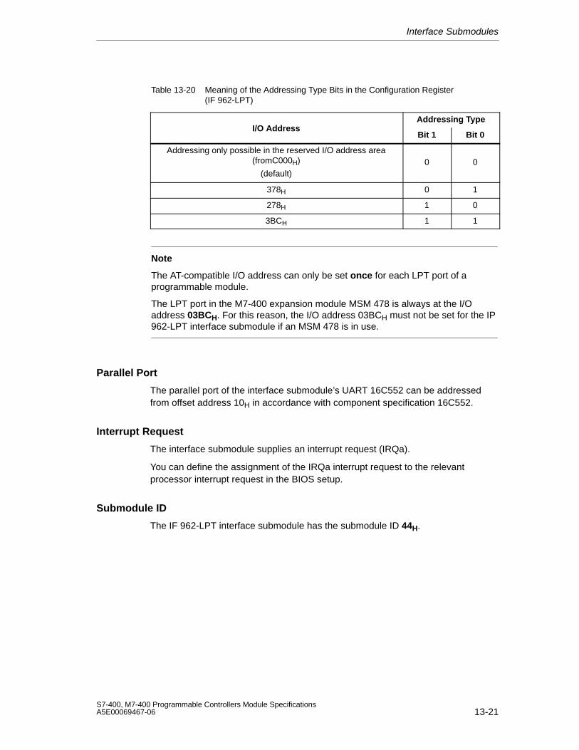
Interface Submodules
13-21S7-400, M7-400 Programmable Controllers Module SpecificationsA5E00069467-06
Table 13-20 Meaning of the Addressing Type Bits in the Configuration Register(IF 962-LPT)
Addressing TypeI/O Address
Bit 1 Bit 0
Addressing only possible in the reserved I/O address area(fromC000H)
(default)0 0
378H 0 1
278H 1 0
3BCH 1 1
Note
The AT-compatible I/O address can only be set once for each LPT port of aprogrammable module.
The LPT port in the M7-400 expansion module MSM 478 is always at the I/Oaddress 03BCH. For this reason, the I/O address 03BCH must not be set for the IP962-LPT interface submodule if an MSM 478 is in use.
Parallel Port
The parallel port of the interface submodule’s UART 16C552 can be addressedfrom offset address 10H in accordance with component specification 16C552.
Interrupt Request
The interface submodule supplies an interrupt request (IRQa).
You can define the assignment of the IRQa interrupt request to the relevantprocessor interrupt request in the BIOS setup.
Submodule ID
The IF 962-LPT interface submodule has the submodule ID 44H.
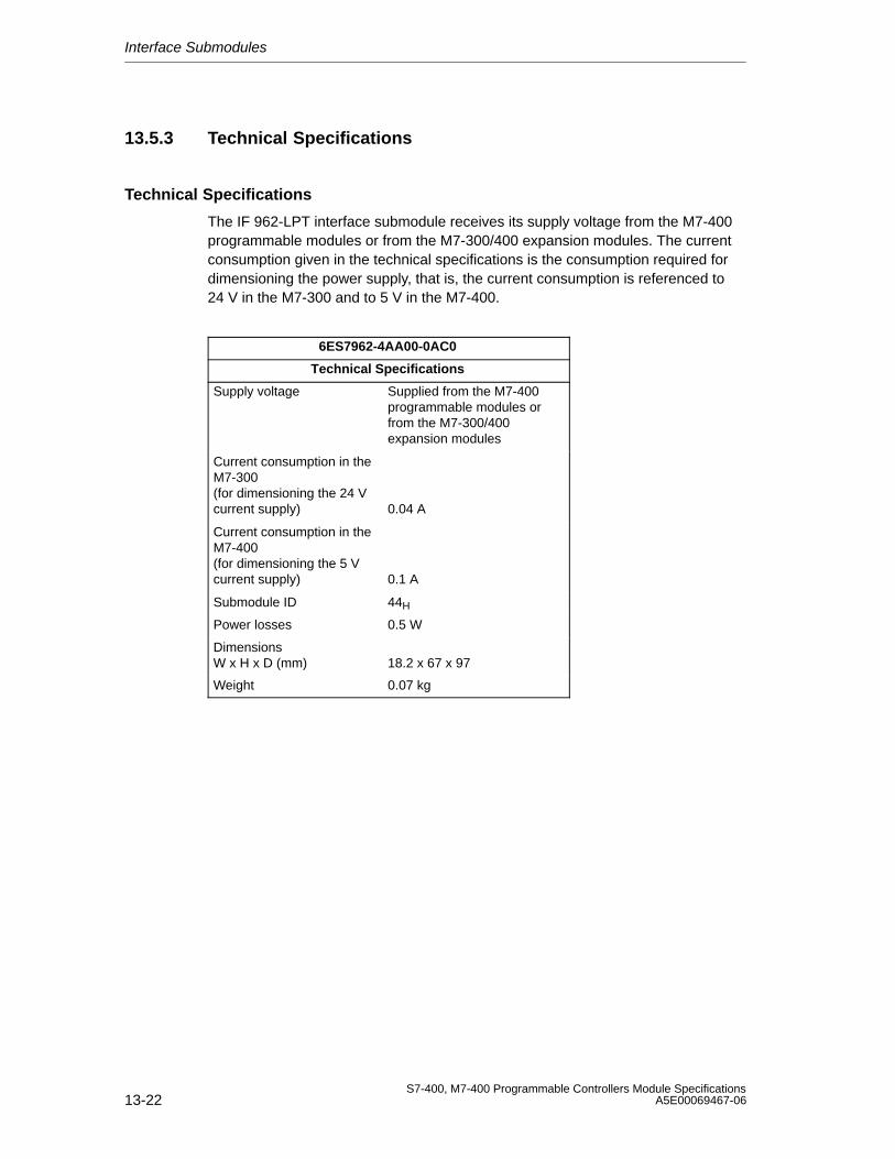
Interface Submodules
13-22S7-400, M7-400 Programmable Controllers Module Specifications
A5E00069467-06
13.5.3 Technical Specifications
Technical Specifications
The IF 962-LPT interface submodule receives its supply voltage from the M7-400programmable modules or from the M7-300/400 expansion modules. The currentconsumption given in the technical specifications is the consumption required fordimensioning the power supply, that is, the current consumption is referenced to24 V in the M7-300 and to 5 V in the M7-400.
6ES7962-4AA00-0AC0
Technical Specifications
Supply voltage Supplied from the M7-400programmable modules orfrom the M7-300/400expansion modules
Current consumption in theM7-300 (for dimensioning the 24 Vcurrent supply) 0.04 A
Current consumption in theM7-400 (for dimensioning the 5 Vcurrent supply) 0.1 A
Submodule ID 44H
Power losses 0.5 W
DimensionsW x H x D (mm) 18.2 x 67 x 97
Weight 0.07 kg
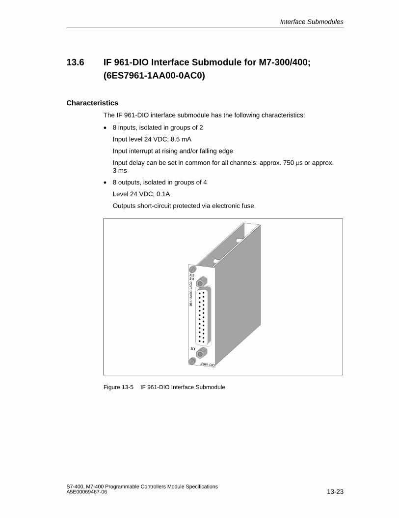
Interface Submodules
13-23S7-400, M7-400 Programmable Controllers Module SpecificationsA5E00069467-06
13.6 IF 961-DIO Interface Submodule for M7-300/400;(6ES7961-1AA00-0AC0)
Characteristics
The IF 961-DIO interface submodule has the following characteristics:
• 8 inputs, isolated in groups of 2
Input level 24 VDC; 8.5 mA
Input interrupt at rising and/or falling edge
Input delay can be set in common for all channels: approx. 750 µs or approx.3 ms
• 8 outputs, isolated in groups of 4
Level 24 VDC; 0.1A
Outputs short-circuit protected via electronic fuse.
Figure 13-5 IF 961-DIO Interface Submodule
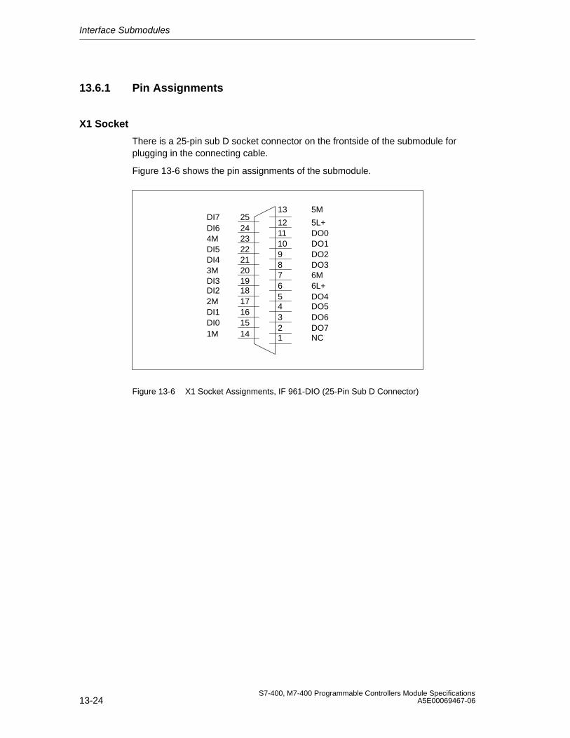
Interface Submodules
13-24S7-400, M7-400 Programmable Controllers Module Specifications
A5E00069467-06
13.6.1 Pin Assignments
X1 Socket
There is a 25-pin sub D socket connector on the frontside of the submodule forplugging in the connecting cable.
Figure 13-6 shows the pin assignments of the submodule.
13 5M
12 5L+11 DO010 DO19 DO28 DO37 6M6 6L+5 DO44 DO53 DO62 DO71 NC
DI7 25DI6 244M 23DI5 22DI4 213M 20DI3 19DI2 182M 17DI1 16DI0 151M 14
Figure 13-6 X1 Socket Assignments, IF 961-DIO (25-Pin Sub D Connector)
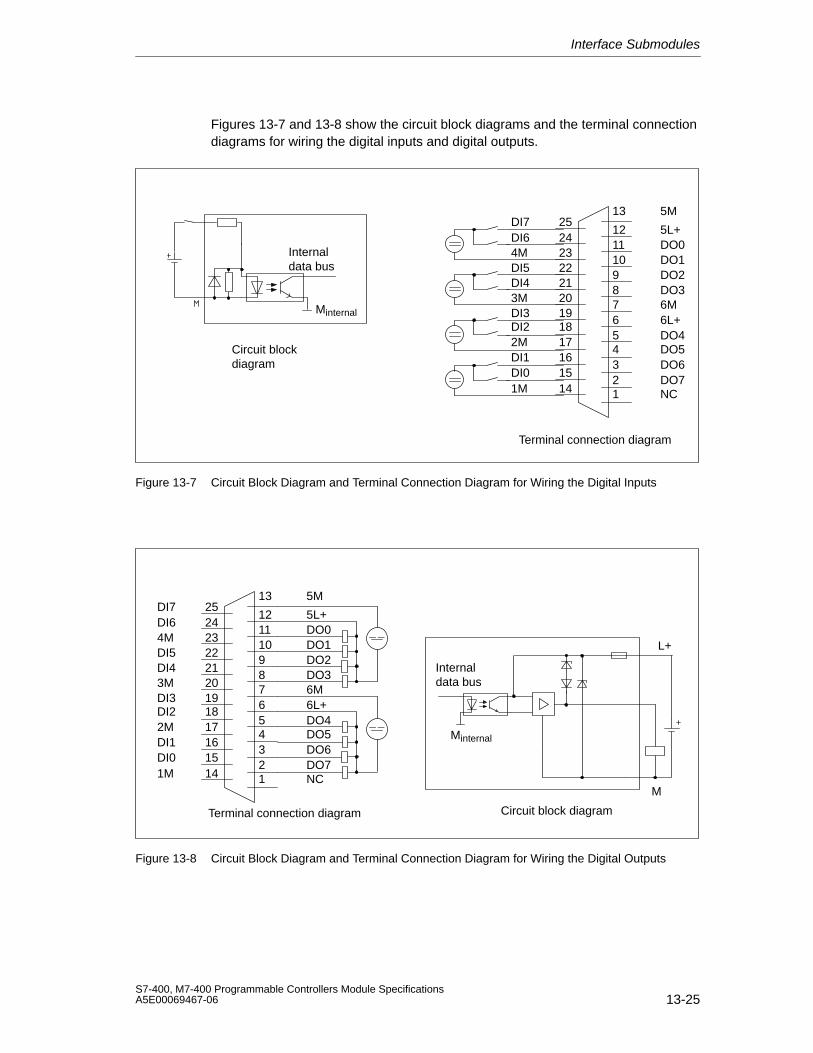
Interface Submodules
13-25S7-400, M7-400 Programmable Controllers Module SpecificationsA5E00069467-06
Figures 13-7 and 13-8 show the circuit block diagrams and the terminal connectiondiagrams for wiring the digital inputs and digital outputs.
Terminal connection diagram
Circuit blockdiagram
Internaldata bus
Minternal
13 5M
12 5L+11 DO010 DO19 DO28 DO37 6M6 6L+5 DO44 DO53 DO62 DO71 NC
DI7 25DI6 244M 23DI5 22DI4 213M 20DI3 19DI2 182M 17DI1 16DI0 151M 14
Figure 13-7 Circuit Block Diagram and Terminal Connection Diagram for Wiring the Digital Inputs
Terminal connection diagram Circuit block diagram
L+
M
Minternal
Internaldata bus
13 5M
12 5L+11 DO010 DO19 DO28 DO37 6M6 6L+5 DO44 DO53 DO62 DO71 NC
DI7 25DI6 244M 23DI5 22DI4 213M 20DI3 19DI2 182M 17DI1 16DI0 151M 14
Figure 13-8 Circuit Block Diagram and Terminal Connection Diagram for Wiring the Digital Outputs
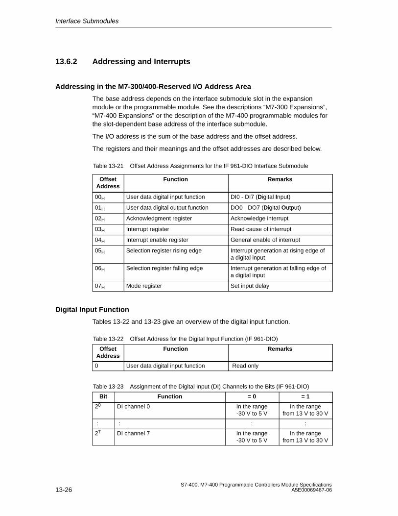
Interface Submodules
13-26S7-400, M7-400 Programmable Controllers Module Specifications
A5E00069467-06
13.6.2 Addressing and Interrupts
Addressing in the M7-300/400-Reserved I/O Address Area
The base address depends on the interface submodule slot in the expansionmodule or the programmable module. See the descriptions “M7-300 Expansions”,“M7-400 Expansions” or the description of the M7-400 programmable modules forthe slot-dependent base address of the interface submodule.
The I/O address is the sum of the base address and the offset address.
The registers and their meanings and the offset addresses are described below.
Table 13-21 Offset Address Assignments for the IF 961-DIO Interface Submodule
OffsetAddress
Function Remarks
00H User data digital input function DI0 - DI7 (Digital Input)
01H User data digital output function DO0 - DO7 (Digital Output)
02H Acknowledgment register Acknowledge interrupt
03H Interrupt register Read cause of interrupt
04H Interrupt enable register General enable of interrupt
05H Selection register rising edge Interrupt generation at rising edge ofa digital input
06H Selection register falling edge Interrupt generation at falling edge ofa digital input
07H Mode register Set input delay
Digital Input Function
Tables 13-22 and 13-23 give an overview of the digital input function.
Table 13-22 Offset Address for the Digital Input Function (IF 961-DIO)
OffsetAddress
Function Remarks
0 User data digital input function Read only
Table 13-23 Assignment of the Digital Input (DI) Channels to the Bits (IF 961-DIO)
Bit Function = 0 = 1
20 DI channel 0 In the range-30 V to 5 V
In the rangefrom 13 V to 30 V
: : : :
27 DI channel 7 In the range-30 V to 5 V
In the rangefrom 13 V to 30 V
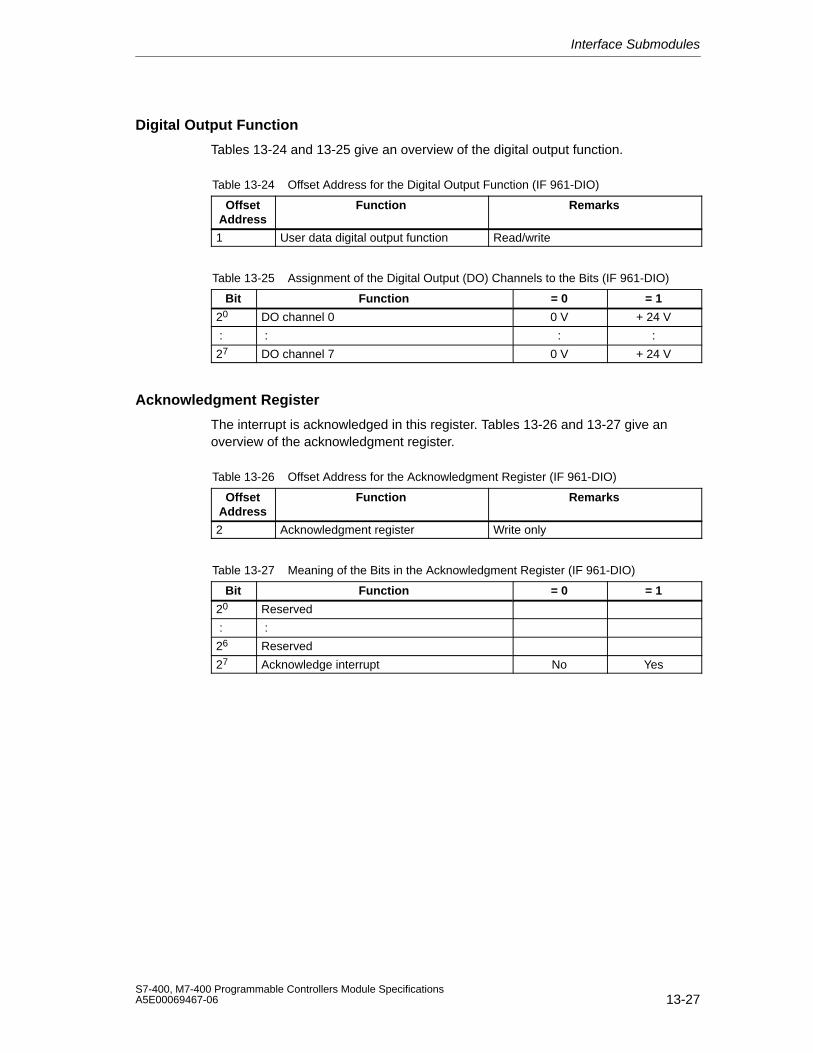
Interface Submodules
13-27S7-400, M7-400 Programmable Controllers Module SpecificationsA5E00069467-06
Digital Output Function
Tables 13-24 and 13-25 give an overview of the digital output function.
Table 13-24 Offset Address for the Digital Output Function (IF 961-DIO)
OffsetAddress
Function Remarks
1 User data digital output function Read/write
Table 13-25 Assignment of the Digital Output (DO) Channels to the Bits (IF 961-DIO)
Bit Function = 0 = 1
20 DO channel 0 0 V + 24 V
: : : :
27 DO channel 7 0 V + 24 V
Acknowledgment Register
The interrupt is acknowledged in this register. Tables 13-26 and 13-27 give anoverview of the acknowledgment register.
Table 13-26 Offset Address for the Acknowledgment Register (IF 961-DIO)
OffsetAddress
Function Remarks
2 Acknowledgment register Write only
Table 13-27 Meaning of the Bits in the Acknowledgment Register (IF 961-DIO)
Bit Function = 0 = 1
20 Reserved
: :
26 Reserved
27 Acknowledge interrupt No Yes

Interface Submodules
13-28S7-400, M7-400 Programmable Controllers Module Specifications
A5E00069467-06
Interrupt Register
The cause of the interrupt is stored in this register. Tables 13-28 and 13-29 give anoverview of the interrupt register.
Table 13-28 Offset Address for the Interrupt Register (IF 961-DIO)
OffsetAddress
Function Remarks
3 Interrupt register Read only
Table 13-29 Meaning of the Bits in the Interrupt Register (IF 961-DIO)
Bit Function = 0 = 1
20 Level change at DI channel 0 No Yes
: : : :
27 Level change at DI channel 7 No Yes
Interrupt Enable Register
Tables 13-30 and 13-31 give an overview of the interrupt enable register.
Table 13-30 Offset Address for the Interrupt Enable Register (IF 961-DIO)
OffsetAddress
Function Remarks
4 Interrupt enable register Read/write
Table 13-31 Meaning of the Bits in the Interrupt Enable Register (IF 961-DIO)
Bit Function = 0 = 1
20 Reserved
: :
26 Reserved
27 Interrupt Disabled Enabled
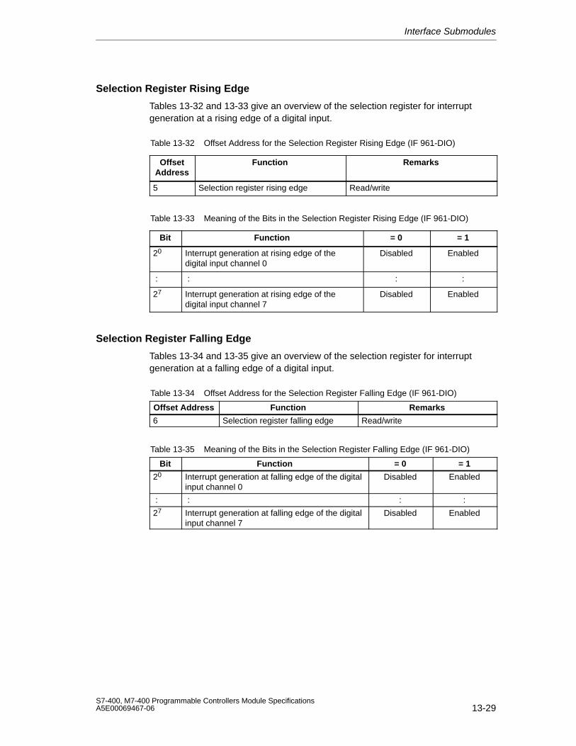
Interface Submodules
13-29S7-400, M7-400 Programmable Controllers Module SpecificationsA5E00069467-06
Selection Register Rising Edge
Tables 13-32 and 13-33 give an overview of the selection register for interruptgeneration at a rising edge of a digital input.
Table 13-32 Offset Address for the Selection Register Rising Edge (IF 961-DIO)
OffsetAddress
Function Remarks
5 Selection register rising edge Read/write
Table 13-33 Meaning of the Bits in the Selection Register Rising Edge (IF 961-DIO)
Bit Function = 0 = 1
20 Interrupt generation at rising edge of thedigital input channel 0
Disabled Enabled
: : : :
27 Interrupt generation at rising edge of thedigital input channel 7
Disabled Enabled
Selection Register Falling Edge
Tables 13-34 and 13-35 give an overview of the selection register for interruptgeneration at a falling edge of a digital input.
Table 13-34 Offset Address for the Selection Register Falling Edge (IF 961-DIO)
Offset Address Function Remarks
6 Selection register falling edge Read/write
Table 13-35 Meaning of the Bits in the Selection Register Falling Edge (IF 961-DIO)
Bit Function = 0 = 1
20 Interrupt generation at falling edge of the digitalinput channel 0
Disabled Enabled
: : : :
27 Interrupt generation at falling edge of the digitalinput channel 7
Disabled Enabled
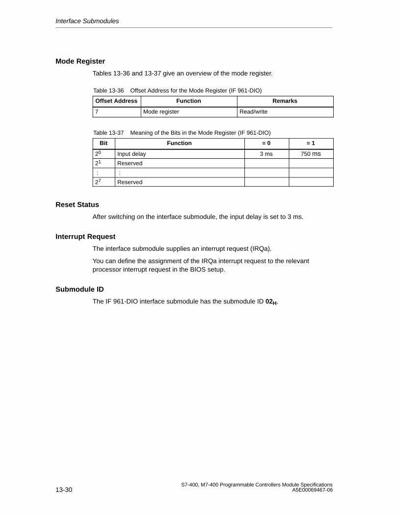
Interface Submodules
13-30S7-400, M7-400 Programmable Controllers Module Specifications
A5E00069467-06
Mode Register
Tables 13-36 and 13-37 give an overview of the mode register.
Table 13-36 Offset Address for the Mode Register (IF 961-DIO)
Offset Address Function Remarks
7 Mode register Read/write
Table 13-37 Meaning of the Bits in the Mode Register (IF 961-DIO)
Bit Function = 0 = 1
20 Input delay 3 ms 750 ms
21 Reserved
: :
27 Reserved
Reset Status
After switching on the interface submodule, the input delay is set to 3 ms.
Interrupt Request
The interface submodule supplies an interrupt request (IRQa).
You can define the assignment of the IRQa interrupt request to the relevantprocessor interrupt request in the BIOS setup.
Submodule ID
The IF 961-DIO interface submodule has the submodule ID 02H.
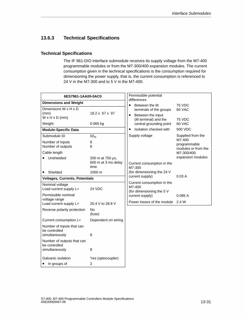
Interface Submodules
13-31S7-400, M7-400 Programmable Controllers Module SpecificationsA5E00069467-06
13.6.3 Technical Specifications
Technical Specifications
The IF 961-DIO interface submodule receives its supply voltage from the M7-400programmable modules or from the M7-300/400 expansion modules. The currentconsumption given in the technical specifications is the consumption required fordimensioning the power supply, that is, the current consumption is referenced to24 V in the M7-300 and to 5 V in the M7-400.
6ES7961-1AA00-0AC0
Dimensions and Weight
Dimensions W x H x D(mm)W x H x D (mm)
18.2 x 67 x 97
Weight 0.065 kg
Module-Specific Data
Submodule ID 02H
Number of inputsNumber of outputs
88
Cable length
• Unshielded
• Shielded
200 m at 750 µs,600 m at 3 ms delaytime
1000 m
Voltages, Currents, Potentials
Nominal voltageLoad current supply L+ 24 VDC
Permissible nominalvoltage rangeLoad current supply L+ 20.4 V to 28.8 V
Reverse polarity protection No(fuse)
Current consumption L+ Dependent on wiring
Number of inputs that canbe controlledsimultaneously 8
Number of outputs that canbe controlledsimultaneously
Galvanic isolation
• In groups of
8
Yes (optocoupler)
2
Permissible potentialdifferences
• Between the Mterminals of the groups
• Between the input(M terminal) and thecentral grounding point
• Isolation checked with
75 VDC60 VAC
75 VDC60 VAC
500 VDC
Supply voltage Supplied from theM7-400programmablemodules or from theM7-300/400expansion modules
Current consumption in theM7-300(for dimensioning the 24 Vcurrent supply) 0.03 A
Current consumption in theM7-400(for dimensioning the 5 Vcurrent supply) 0.085 A
Power losses of the module 2.4 W
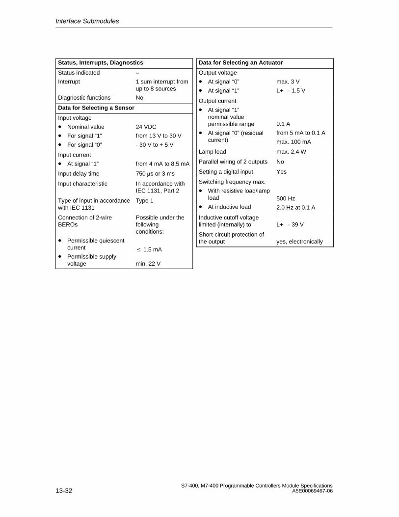
Interface Submodules
13-32S7-400, M7-400 Programmable Controllers Module Specifications
A5E00069467-06
Status, Interrupts, Diagnostics
Status indicated
Interrupt
Diagnostic functions
–
1 sum interrupt fromup to 8 sources
No
Data for Selecting a Sensor
Input voltage
• Nominal value
• For signal “1”
• For signal “0”
24 VDC
from 13 V to 30 V
- 30 V to + 5 V
Input current
• At signal “1” from 4 mA to 8.5 mA
Input delay time 750 µs or 3 ms
Input characteristic In accordance withIEC 1131, Part 2
Type of input in accordancewith IEC 1131
Type 1
Connection of 2-wireBEROs
• Permissible quiescentcurrent
• Permissible supplyvoltage
Possible under thefollowingconditions:
1.5 mA
min. 22 V
Data for Selecting an Actuator
Output voltage
• At signal “0”
• At signal “1”
max. 3 V
L+ - 1.5 V
Output current
• At signal “1”nominal valuepermissible range
• At signal “0” (residualcurrent)
0.1 A
from 5 mA to 0.1 A
max. 100 mA
Lamp load max. 2.4 W
Parallel wiring of 2 outputs No
Setting a digital input Yes
Switching frequency max.
• With resistive load/lampload
• At inductive load500 Hz
2.0 Hz at 0.1 A
Inductive cutoff voltagelimited (internally) to L+ - 39 V
Short-circuit protection ofthe output yes, electronically
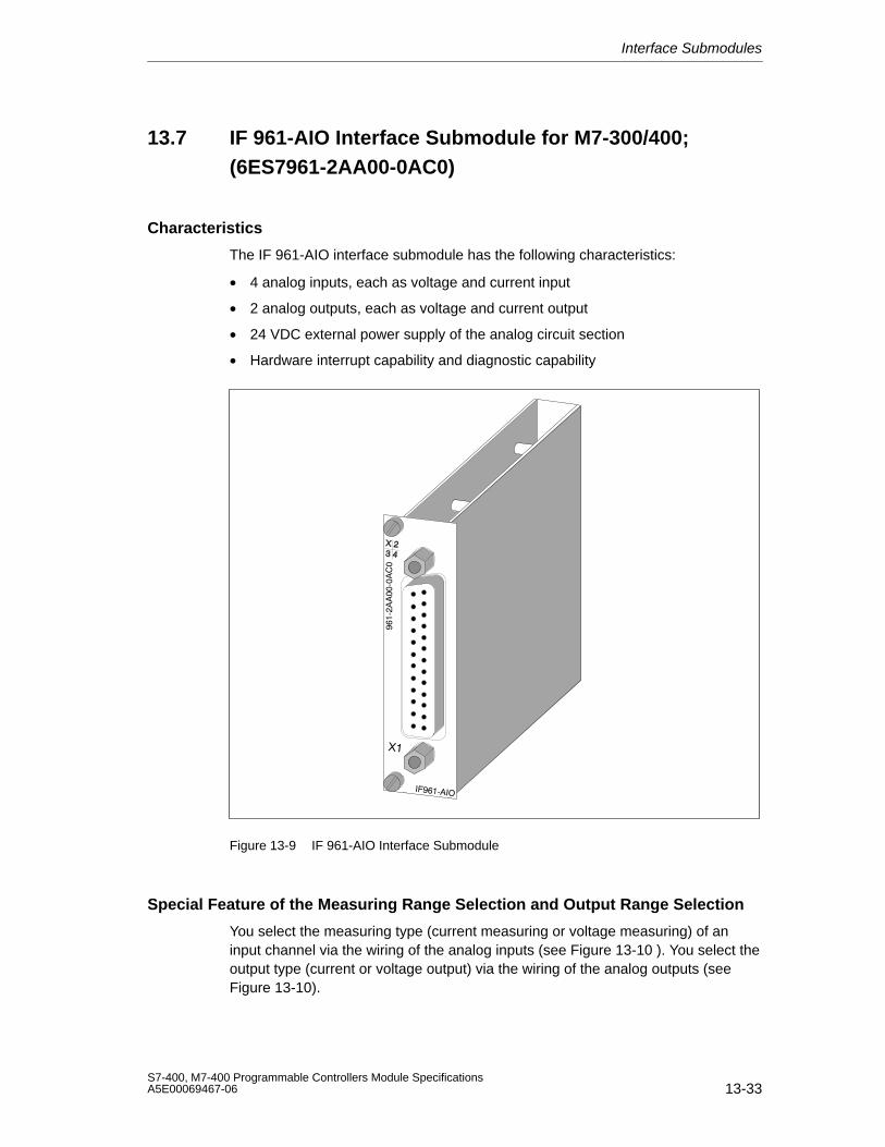
Interface Submodules
13-33S7-400, M7-400 Programmable Controllers Module SpecificationsA5E00069467-06
13.7 IF 961-AIO Interface Submodule for M7-300/400;(6ES7961-2AA00-0AC0)
Characteristics
The IF 961-AIO interface submodule has the following characteristics:
• 4 analog inputs, each as voltage and current input
• 2 analog outputs, each as voltage and current output
• 24 VDC external power supply of the analog circuit section
• Hardware interrupt capability and diagnostic capability
Figure 13-9 IF 961-AIO Interface Submodule
Special Feature of the Measuring Range Selection and Output Range Selection
You select the measuring type (current measuring or voltage measuring) of aninput channel via the wiring of the analog inputs (see Figure 13-10 ). You select theoutput type (current or voltage output) via the wiring of the analog outputs (seeFigure 13-10).

Interface Submodules
13-34S7-400, M7-400 Programmable Controllers Module Specifications
A5E00069467-06
13.7.1 Pin Assignments and Terminal Connection Diagram
X1 Socket
There is a 25-pin sub D socket connector on the frontside of the submodule forplugging in the connecting cable.
Figure 13-10 shows the assignments for the X1 socket and the terminalconnection diagram of the submodule.
V
Pinout diagram voltage measurement
M0-
MI1+MV2+M2-
M3-MI3+
QI1
CH 0
CH 1
CH2
CH 3
CH 0
CH1M
M1-
Pinout diagram voltage output
MV1+M1- CH 1
MV3+M3-
CH 3
MI0+CH 0
M0-
M2-MI2+
CH 2
QV1S1
CH1
QV0S0
QI0
CH 0
RL
L +
RLV
Pinout diagram currentmeasurement
2
4
6
8
10
11
13
1516
1718
1920
2122
23
2412
9
M
Pinout diagram current output
RL
1 L +
A
Ground barof the PLC
RLA
Ground barof the PLC
2
4
6
8
10
11
13
1516
1718
1920
2122
23
2412
9
1MV0+
13 M
12 S111 QV110 QV09 S08 MV3+7 NC6 MV2+5 NC4 MV1+3 NC2 MV0+1 L+
L2+ 25QI1 24QI0 23M3- 22MI3+ 21M2- 20MI2+ 19M1- 18MI1+ 17M0- 16MI0+ 15L1+ 14
Figure 13-10 X1 Socket Assignments (25-Pin Sub D Connector) and Terminal Connection Diagram of theIF 961-AIO
Note
Use only shielded cables for connecting the inputs and outputs.
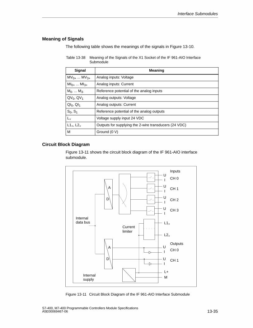
Interface Submodules
13-35S7-400, M7-400 Programmable Controllers Module SpecificationsA5E00069467-06
Meaning of Signals
The following table shows the meanings of the signals in Figure 13-10.
Table 13-38 Meaning of the Signals of the X1 Socket of the IF 961-AIO InterfaceSubmodule
Signal Meaning
MV0+ ... MV3+ Analog inputs: Voltage
MI0+ ... MI3+ Analog inputs: Current
M0- ... M3- Reference potential of the analog inputs
QV0, QV1 Analog outputs: Voltage
QI0, QI1 Analog outputs: Current
S0, S1 Reference potential of the analog outputs
L+ Voltage supply input 24 VDC
L1+, L2+ Outputs for supplying the 2-wire transducers (24 VDC)
M Ground (0 V)
Circuit Block Diagram
Figure 13-11 shows the circuit block diagram of the IF 961-AIO interfacesubmodule.
M
L+
A
D
Internalsupply
UI
UI
UI
UI
CH 0
CH 1
CH 2
CH 3
A
D
UI
UI
CH 0
CH 1
Inputs
Outputs
Internaldata bus L1+
L2+
Currentlimiter
Figure 13-11 Circuit Block Diagram of the IF 961-AIO Interface Submodule
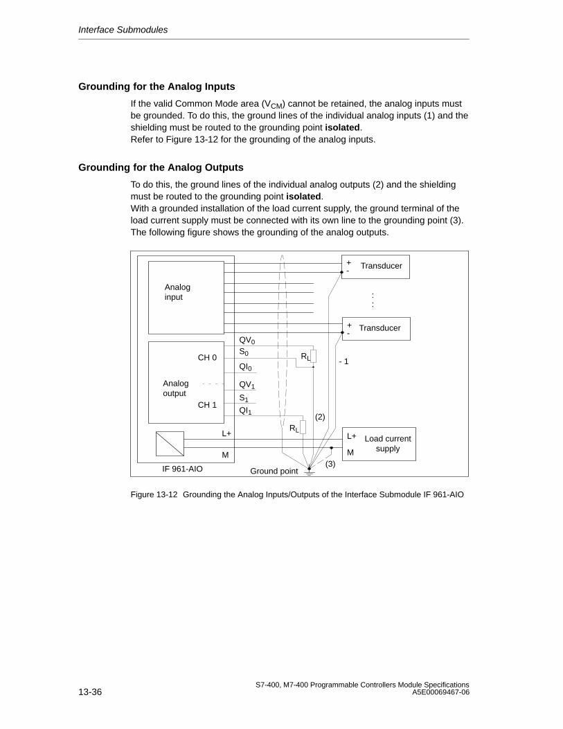
Interface Submodules
13-36S7-400, M7-400 Programmable Controllers Module Specifications
A5E00069467-06
Grounding for the Analog Inputs
If the valid Common Mode area (VCM) cannot be retained, the analog inputs mustbe grounded. To do this, the ground lines of the individual analog inputs (1) and theshielding must be routed to the grounding point isolated.Refer to Figure 13-12 for the grounding of the analog inputs.
Grounding for the Analog Outputs
To do this, the ground lines of the individual analog outputs (2) and the shieldingmust be routed to the grounding point isolated.With a grounded installation of the load current supply, the ground terminal of theload current supply must be connected with its own line to the grounding point (3).The following figure shows the grounding of the analog outputs.
M
L+
(3)
RL
Analog input
Ground point
Load currentsupplyM
L+
Analog output
RL
CH 0
CH 1
IF 961-AIO
QI0
QI1
S0
QV0
QV1
S1
Transducer-+
Transducer-+
::
- 1
(2)
Figure 13-12 Grounding the Analog Inputs/Outputs of the Interface Submodule IF 961-AIO
Interface Submodules
13-37S7-400, M7-400 Programmable Controllers Module SpecificationsA5E00069467-06
13.7.2 Connecting Measured Value Sensors to Analog Inputs
Introduction
Depending on the measuring type, you can connect various measured valuesensors to the analog inputs:
• Voltage sensors
• Current sensors as
– two-wire transducers
– four-wire transducers
• Resistance
This section describes how to connect the measured value sensors and what tolook out for when connecting the measured value sensors.
Connecting Measured Value Sensors to Analog Inputs
The maximum permissible voltage difference (VCM = 8 V AC) between the inputsand the internal ground must not be exceeded.
The measuring ranges (current/voltage) are selected via the wiring of the frontconnector and by calling the software driver provided for the measuring range.
Unswitched Channels
You must short-circuit unswitched input channels and ground them. This achievesoptimal noise immunity for the analog module.
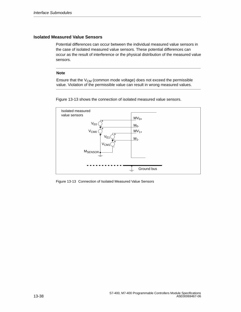
Interface Submodules
13-38S7-400, M7-400 Programmable Controllers Module Specifications
A5E00069467-06
Isolated Measured Value Sensors
Potential differences can occur between the individual measured value sensors inthe case of isolated measured value sensors. These potential differences canoccur as the result of interference or the physical distribution of the measured valuesensors.
Note
Ensure that the VCM (common mode voltage) does not exceed the permissiblevalue. Violation of the permissible value can result in wrong measured values.
Figure 13-13 shows the connection of isolated measured value sensors.
+
-VE0
Isolated measuredvalue sensors
Ground bus
MV0+
M0-
+-
VE1
MV1+
M1-
+
-VCM0
+-
VCM1
MSENSOR
Figure 13-13 Connection of Isolated Measured Value Sensors
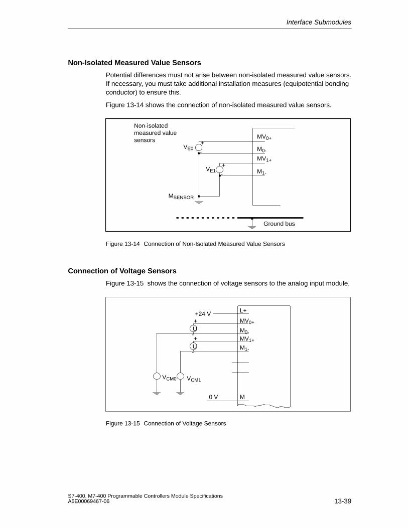
Interface Submodules
13-39S7-400, M7-400 Programmable Controllers Module SpecificationsA5E00069467-06
Non-Isolated Measured Value Sensors
Potential differences must not arise between non-isolated measured value sensors.If necessary, you must take additional installation measures (equipotential bondingconductor) to ensure this.
Figure 13-14 shows the connection of non-isolated measured value sensors.
+
-VE0
Non-isolatedmeasured valuesensors
Ground bus
+-
VE1
MSENSOR
MV0+
M0-
MV1+
M1-
Figure 13-14 Connection of Non-Isolated Measured Value Sensors
Connection of Voltage Sensors
Figure 13-15 shows the connection of voltage sensors to the analog input module.
+
-U
+
-U
+24 VMV0+
M0-
MV1+
M1-
M
L+
VCM1VCM0
0 V
Figure 13-15 Connection of Voltage Sensors
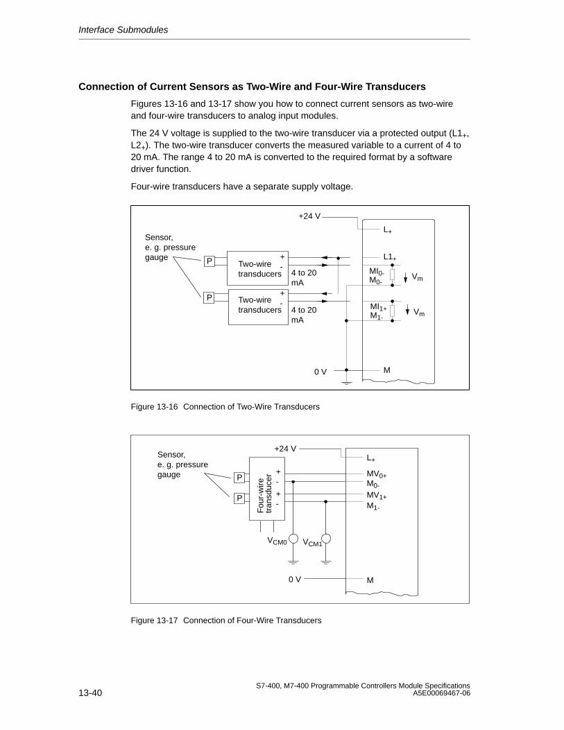
Interface Submodules
13-40S7-400, M7-400 Programmable Controllers Module Specifications
A5E00069467-06
Connection of Current Sensors as Two-Wire and Four-Wire Transducers
Figures 13-16 and 13-17 show you how to connect current sensors as two-wireand four-wire transducers to analog input modules.
The 24 V voltage is supplied to the two-wire transducer via a protected output (L1+,L2+). The two-wire transducer converts the measured variable to a current of 4 to20 mA. The range 4 to 20 mA is converted to the required format by a softwaredriver function.
Four-wire transducers have a separate supply voltage.
Two-wiretransducers
Two-wiretransducers
+24 V
Sensor,e. g. pressuregauge P
P
+-
+-
L+
M
L1+
M0-
MI1+M1-
0 V
MI0- Vm
Vm
4 to 20mA
4 to 20mA
Figure 13-16 Connection of Two-Wire Transducers
+24 V
tran
sduc
erF
our-
wire
+-
+-
Sensor,e. g. pressuregauge P
P
L+
M
MV0+M0-
MV1+M1-
VCM1VCM0
0 V
Figure 13-17 Connection of Four-Wire Transducers
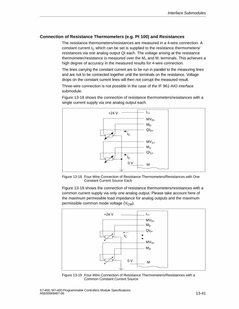
Interface Submodules
13-41S7-400, M7-400 Programmable Controllers Module SpecificationsA5E00069467-06
Connection of Resistance Thermometers (e.g. Pt 100) and ResistancesThe resistance thermometers/resistances are measured in a 4-wire connection. Aconstant current IC which can be set is supplied to the resistance thermometers/resistances via one analog output QI each. The voltage arising at the resistancethermometer/resistance is measured over the M+ and M- terminals. This achieves ahigh degree of accuracy in the measured results for 4-wire connection.
The lines carrying the constant current are to be run in parallel to the measuring linesand are not to be connected together until the terminals on the resistance. Voltagedrops on the constant current lines will then not corrupt the measured result.
Three-wire connection is not possible in the case of the IF 961-AIO interfacesubmodule.
Figure 13-18 shows the connection of resistance thermometers/resistances with asingle current supply via one analog output each.
IC
L+
MV0+
M0-
QI0+
+24 V
M
IC
MV1+
M1-
QI1+
0 V
Figure 13-18 Four-Wire Connection of Resistance Thermometers/Resistances with OneConstant Current Source Each
Figure 13-19 shows the connection of resistance thermometers/resistances with acommon current supply via only one analog output. Please take account here ofthe maximum permissible load impedance for analog outputs and the maximumpermissible common mode voltage (VCM).
IC
L+
MV0+M0-
QI0+
+24 V
M
MV3+
M3-
0 V
Figure 13-19 Four-Wire Connection of Resistance Thermometers/Resistances with aCommon Constant Current Source
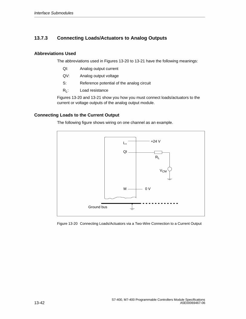
Interface Submodules
13-42S7-400, M7-400 Programmable Controllers Module Specifications
A5E00069467-06
13.7.3 Connecting Loads/Actuators to Analog Outputs
Abbreviations Used
The abbreviations used in Figures 13-20 to 13-21 have the following meanings:
QI: Analog output current
QV: Analog output voltage
S: Reference potential of the analog circuit
RL: Load resistance
Figures 13-20 and 13-21 show you how you must connect loads/actuators to thecurrent or voltage outputs of the analog output module.
Connecting Loads to the Current Output
The following figure shows wiring on one channel as an example.
+24 V
RL
L+
QI
Ground bus
VCM
M 0 V
Figure 13-20 Connecting Loads/Actuators via a Two-Wire Connection to a Current Output
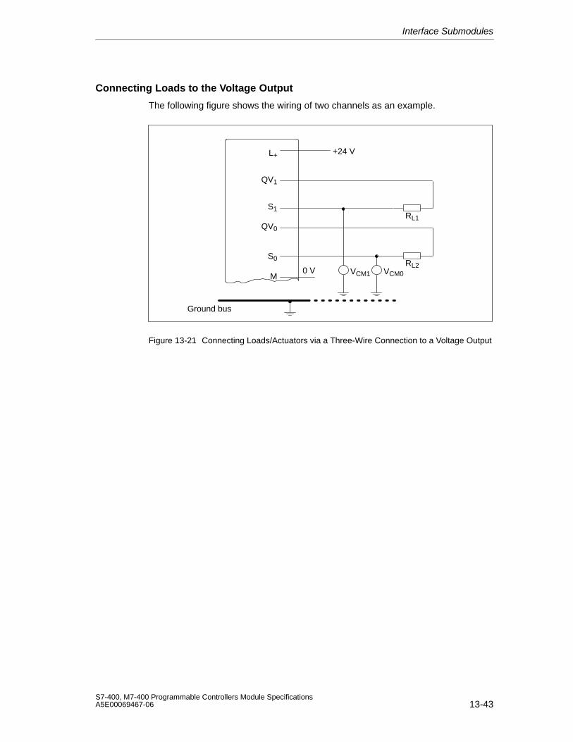
Interface Submodules
13-43S7-400, M7-400 Programmable Controllers Module SpecificationsA5E00069467-06
Connecting Loads to the Voltage Output
The following figure shows the wiring of two channels as an example.
+24 V
RL1
L+
QV1
S1
Ground bus
QV0
S0RL2
M0 V VCM1 VCM0
Figure 13-21 Connecting Loads/Actuators via a Three-Wire Connection to a Voltage Output
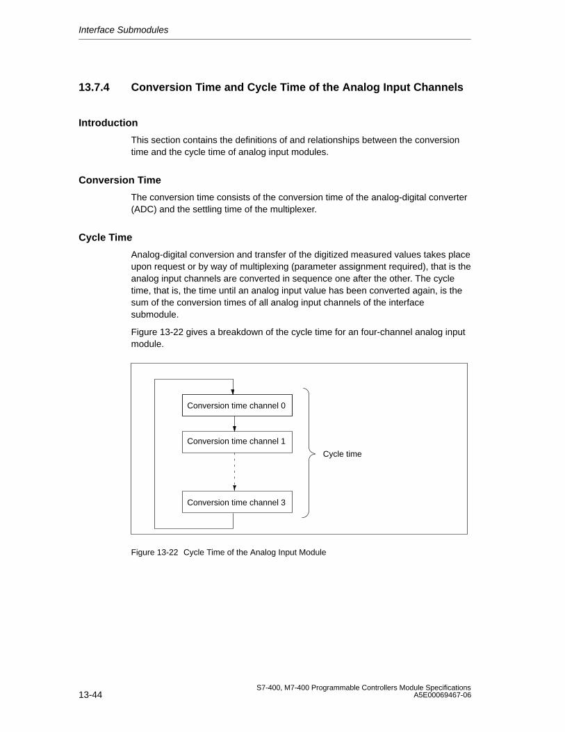
Interface Submodules
13-44S7-400, M7-400 Programmable Controllers Module Specifications
A5E00069467-06
13.7.4 Conversion Time and Cycle Time of the Analog Input Channels
Introduction
This section contains the definitions of and relationships between the conversiontime and the cycle time of analog input modules.
Conversion Time
The conversion time consists of the conversion time of the analog-digital converter(ADC) and the settling time of the multiplexer.
Cycle Time
Analog-digital conversion and transfer of the digitized measured values takes placeupon request or by way of multiplexing (parameter assignment required), that is theanalog input channels are converted in sequence one after the other. The cycletime, that is, the time until an analog input value has been converted again, is thesum of the conversion times of all analog input channels of the interfacesubmodule.
Figure 13-22 gives a breakdown of the cycle time for an four-channel analog inputmodule.
Conversion time channel 0
Conversion time channel 1
Conversion time channel 3
Cycle time
Figure 13-22 Cycle Time of the Analog Input Module
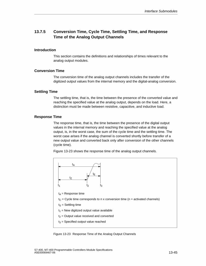
Interface Submodules
13-45S7-400, M7-400 Programmable Controllers Module SpecificationsA5E00069467-06
13.7.5 Conversion Time, Cycle Time, Settling Time, and ResponseTime of the Analog Output Channels
Introduction
This section contains the definitions and relationships of times relevant to theanalog output modules.
Conversion Time
The conversion time of the analog output channels includes the transfer of thedigitized output values from the internal memory and the digital-analog conversion.
Settling Time
The settling time, that is, the time between the presence of the converted value andreaching the specified value at the analog output, depends on the load. Here, adistinction must be made between resistive, capacitive, and inductive load.
Response Time
The response time, that is, the time between the presence of the digital outputvalues in the internal memory and reaching the specified value at the analogoutput, is, in the worst case, the sum of the cycle time and the settling time. Theworst case arises if the analog channel is converted shortly before transfer of anew output value and converted back only after conversion of the other channels(cycle time).
Figure 13-23 shows the response time of the analog output channels.
tA
tZ
tE
t1 t2
tA = Response time
tC = Cycle time corresponds to n x conversion time (n = activated channels)
tS = Settling time
t1 = New digitized output value available
t2 = Output value received and converted
t3 = Specified output value reached
t3
Figure 13-23 Response Time of the Analog Output Channels
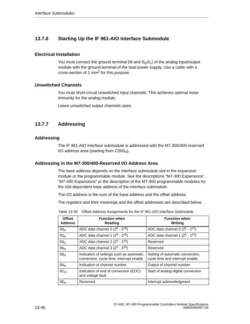
Interface Submodules
13-46S7-400, M7-400 Programmable Controllers Module Specifications
A5E00069467-06
13.7.6 Starting Up the IF 961-AIO Interface Submodule
Electrical Installation
You must connect the ground terminal (M and S0/S1) of the analog input/outputmodule with the ground terminal of the load power supply. Use a cable with across-section of 1 mm2 for this purpose.
Unswitched Channels
You must short-circuit unswitched input channels. This achieves optimal noiseimmunity for the analog module.
Leave unswitched output channels open.
13.7.7 Addressing
Addressing
The IF 961-AIO interface submodule is addressed with the M7-300/400-reservedI/O address area (starting from C000H).
Addressing in the M7-300/400-Reserved I/O Address Area
The base address depends on the interface submodule slot in the expansionmodule or the programmable module. See the descriptions “M7-300 Expansions”,“M7-400 Expansions” or the description of the M7-400 programmable modules forthe slot-dependent base address of the interface submodule.
The I/O address is the sum of the base address and the offset address.
The registers and their meanings and the offset addresses are described below.
Table 13-39 Offset Address Assignments for the IF 961-AIO Interface Submodule
OffsetAddress
Function whenReading
Function whenWriting
00H ADC data channel 0 (20 - 215) ADC data channel 0 (20 - 215)
02H ADC data channel 1 (20 - 215) ADC data channel 1 (20 - 215)
04H ADC data channel 2 (20 - 215) Reserved
06H ADC data channel 3 (20 - 215) Reserved
08H Indication of settings such as automaticconversion, cycle time, interrupt enable
Setting of automatic conversion, cycle time and interrupt enable
0AH Indication of channel number Output of channel number
0CH Indication of end of conversion (EOC)and voltage fault
Start of analog-digital conversion
0EH Reserved Interrupt acknowledgment
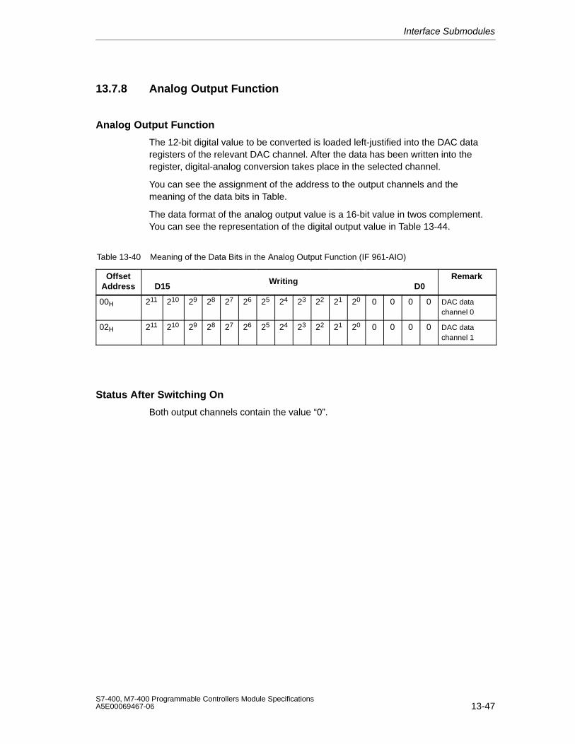
Interface Submodules
13-47S7-400, M7-400 Programmable Controllers Module SpecificationsA5E00069467-06
13.7.8 Analog Output Function
Analog Output Function
The 12-bit digital value to be converted is loaded left-justified into the DAC dataregisters of the relevant DAC channel. After the data has been written into theregister, digital-analog conversion takes place in the selected channel.
You can see the assignment of the address to the output channels and themeaning of the data bits in Table.
The data format of the analog output value is a 16-bit value in twos complement.You can see the representation of the digital output value in Table 13-44.
Table 13-40 Meaning of the Data Bits in the Analog Output Function (IF 961-AIO)
OffsetAddress D15
WritingD0
Remark
00H 211 210 29 28 27 26 25 24 23 22 21 20 0 0 0 0 DAC datachannel 0
02H 211 210 29 28 27 26 25 24 23 22 21 20 0 0 0 0 DAC datachannel 1
Status After Switching On
Both output channels contain the value “0”.
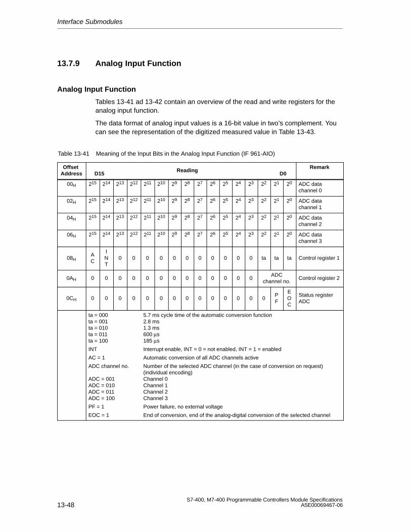
Interface Submodules
13-48S7-400, M7-400 Programmable Controllers Module Specifications
A5E00069467-06
13.7.9 Analog Input Function
Analog Input Function
Tables 13-41 ad 13-42 contain an overview of the read and write registers for theanalog input function.
The data format of analog input values is a 16-bit value in two’s complement. Youcan see the representation of the digitized measured value in Table 13-43.
Table 13-41 Meaning of the Input Bits in the Analog Input Function (IF 961-AIO)
Offset Address D15
ReadingD0
Remark
00H 215 214 213 212 211 210 29 28 27 26 25 24 23 22 21 20 ADC datachannel 0
02H 215 214 213 212 211 210 29 28 27 26 25 24 23 22 21 20 ADC datachannel 1
04H 215 214 213 212 211 210 29 28 27 26 25 24 23 22 21 20 ADC datachannel 2
06H 215 214 213 212 211 210 29 28 27 26 25 24 23 22 21 20 ADC datachannel 3
08HAC
INT
0 0 0 0 0 0 0 0 0 0 0 ta ta ta Control register 1
0AH 0 0 0 0 0 0 0 0 0 0 0 0 0ADC
channel no.Control register 2
0CH 0 0 0 0 0 0 0 0 0 0 0 0 0 0PF
EOC
Status registerADC
ta = 000ta = 001ta = 010ta = 011ta = 100
INT
AC = 1
ADC channel no.
ADC = 001ADC = 010ADC = 011ADC = 100
PF = 1
EOC = 1
5.7 ms cycle time of the automatic conversion function2.8 ms1.3 ms600 µs185 µs
Interrupt enable, INT = 0 = not enabled, INT = 1 = enabled
Automatic conversion of all ADC channels active
Number of the selected ADC channel (in the case of conversion on request)(individual encoding)Channel 0Channel 1Channel 2Channel 3
Power failure, no external voltage
End of conversion, end of the analog-digital conversion of the selected channel
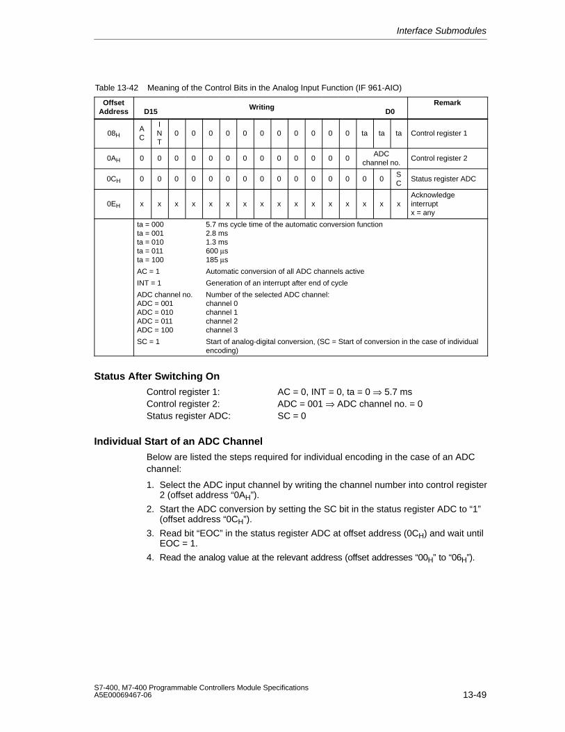
Interface Submodules
13-49S7-400, M7-400 Programmable Controllers Module SpecificationsA5E00069467-06
Table 13-42 Meaning of the Control Bits in the Analog Input Function (IF 961-AIO)
OffsetAddress D15
WritingD0
Remark
08HAC
INT
0 0 0 0 0 0 0 0 0 0 0 ta ta ta Control register 1
0AH 0 0 0 0 0 0 0 0 0 0 0 0 0ADC
channel no.Control register 2
0CH 0 0 0 0 0 0 0 0 0 0 0 0 0 0 0SC
Status register ADC
0EH x x x x x x x x x x x x x x x xAcknowledgeinterruptx = any
ta = 000ta = 001ta = 010ta = 011ta = 100
AC = 1
INT = 1
ADC channel no.ADC = 001ADC = 010ADC = 011ADC = 100
SC = 1
5.7 ms cycle time of the automatic conversion function2.8 ms1.3 ms600 µs185 µs
Automatic conversion of all ADC channels active
Generation of an interrupt after end of cycle
Number of the selected ADC channel:channel 0channel 1channel 2channel 3
Start of analog-digital conversion, (SC = Start of conversion in the case of individualencoding)
Status After Switching On
Control register 1: AC = 0, INT = 0, ta = 0 ⇒ 5.7 msControl register 2: ADC = 001 ⇒ ADC channel no. = 0Status register ADC: SC = 0
Individual Start of an ADC Channel
Below are listed the steps required for individual encoding in the case of an ADCchannel:
1. Select the ADC input channel by writing the channel number into control register2 (offset address “0AH”).
2. Start the ADC conversion by setting the SC bit in the status register ADC to “1”(offset address “0CH”).
3. Read bit “EOC” in the status register ADC at offset address (0CH) and wait untilEOC = 1.
4. Read the analog value at the relevant address (offset addresses “00H” to “06H”).
Interface Submodules
13-50S7-400, M7-400 Programmable Controllers Module Specifications
A5E00069467-06
Cyclic Conversion of the ADC Channels
Below are listed the steps required for cyclic conversion of the ADC channels:
1. Set the AC bit in control register 1 to “1” (offset address “08H”).
2. Wait for interrupt.
3. Read the values at the relevant address (offset addresses “00H” to “06H”).
4. Acknowledge the interrupt by writing to the offset address “0EH”, data bits 0 to15 are irrelevant here.
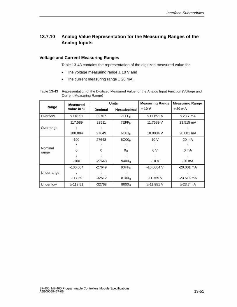
Interface Submodules
13-51S7-400, M7-400 Programmable Controllers Module SpecificationsA5E00069467-06
13.7.10 Analog Value Representation for the Measuring Ranges of theAnalog Inputs
Voltage and Current Measuring Ranges
Table 13-43 contains the representation of the digitized measured value for
• The voltage measuring range ± 10 V and
• The current measuring range ± 20 mA.
Table 13-43 Representation of the Digitized Measured Value for the Analog Input Function (Voltage andCurrent Measuring Range)
Measured Units Measuring Range Measuring RangeRange
MeasuredValue in % Decimal Hexadecimal 10 V 20 mA
Overflow ≤ 118.51 32767 7FFFH ≤ 11.851 V ≤ 23.7 mA
Overrange
117.589
:
100.004
32511
:
27649
7EFFH
:
6C01H
11.7589 V
:
10.0004 V
23.515 mA
:
20.001 mA
Nominalrange
100
:
0
:
-100
27648
:
0
:
-27648
6C00H
:
0H
:
9400H
10 V
:
0 V
:
-10 V
20 mA
:
0 mA
:
-20 mA
Underrange
-100.004
:
-117.59
-27649
:
-32512
93FFH
:
8100H
-10.0004 V
:
-11.759 V
-20.001 mA
:
-23.516 mA
Underflow ≥-118.51 -32768 8000H ≥-11.851 V ≥-23.7 mA
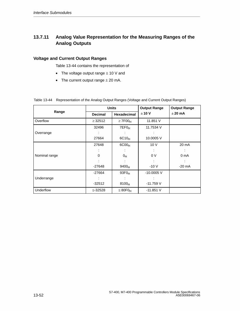
Interface Submodules
13-52S7-400, M7-400 Programmable Controllers Module Specifications
A5E00069467-06
13.7.11 Analog Value Representation for the Measuring Ranges of theAnalog Outputs
Voltage and Current Output Ranges
Table 13-44 contains the representation of
• The voltage output range ± 10 V and
• The current output range ± 20 mA.
Table 13-44 Representation of the Analog Output Ranges (Voltage and Current Output Ranges)
Units Output Range Output RangeRange
Decimal Hexadecimal 10 V 20 mA
Overflow ≥ 32512 ≥ 7F00H 11.851 V
Overrange
32496
:
27664
7EF0H
:
6C10H
11.7534 V
:
10.0005 V
Nominal range
27648
:
0
:
-27648
6C00H
:
0H
:
9400H
10 V
:
0 V
:
-10 V
20 mA
:
0 mA
:
-20 mA
Underrange
-27664
:
-32512
93F0H
:
8100H
-10.0005 V
:
-11.759 V
Underflow ≤-32528 ≤ 80F0H -11.851 V
Interface Submodules
13-53S7-400, M7-400 Programmable Controllers Module SpecificationsA5E00069467-06
13.7.12 Diagnostics, Interrupts, and Submodule ID
Interrupt Request
The interface submodule supplies an interrupt request (IRQa).
You can define the assignment of the IRQa interrupt request to the relevantprocessor interrupt request in the BIOS setup.
Diagnostic and Hardware Interrupts
If the interface submodule IF 961-AIO was assigned parameters for cyclicconversion, you have the possibility of initiating hardware interrupts at theend-of-cycle. It is also possible to initiate a diagnostic interrupt if a hardwareinterrupt is lost.
Submodule ID
The IF 961-DIO interface submodule has the submodule ID 01H.
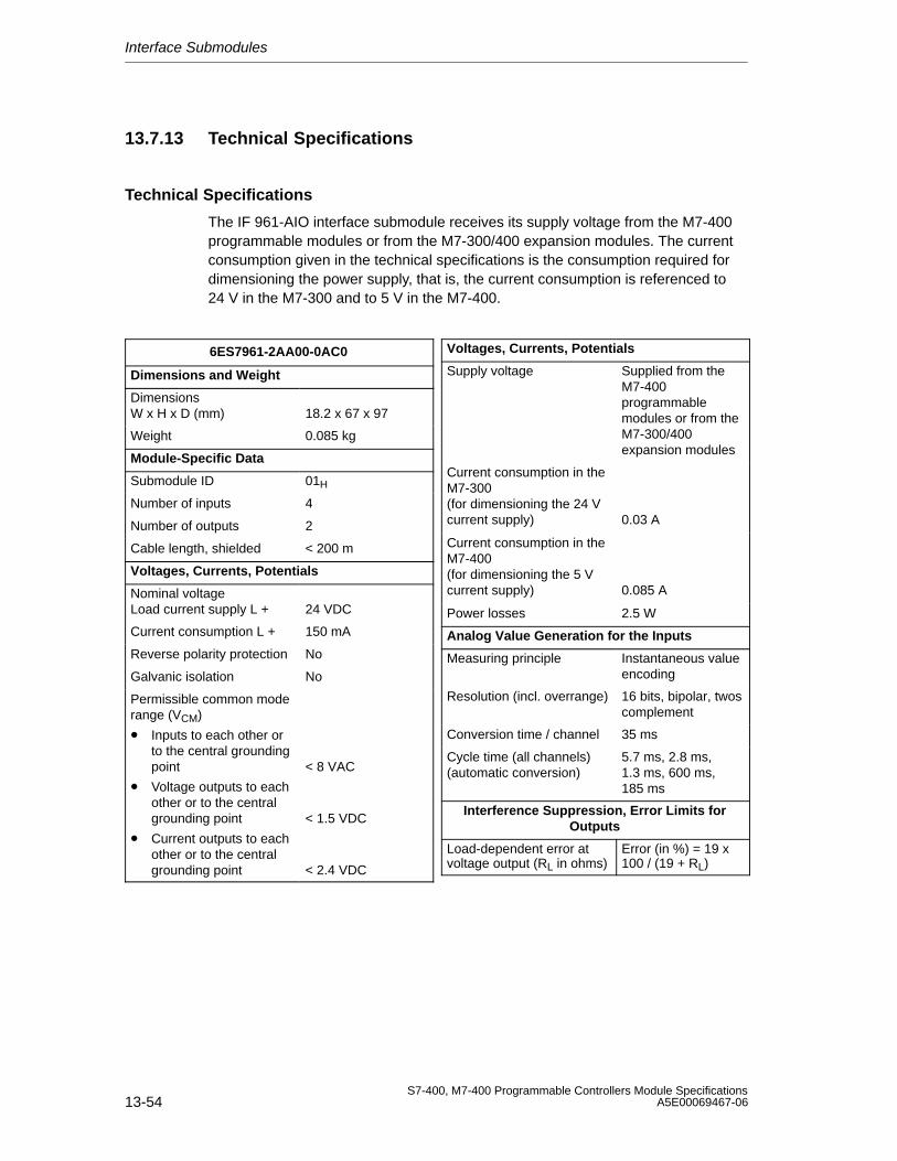
Interface Submodules
13-54S7-400, M7-400 Programmable Controllers Module Specifications
A5E00069467-06
13.7.13 Technical Specifications
Technical Specifications
The IF 961-AIO interface submodule receives its supply voltage from the M7-400programmable modules or from the M7-300/400 expansion modules. The currentconsumption given in the technical specifications is the consumption required fordimensioning the power supply, that is, the current consumption is referenced to24 V in the M7-300 and to 5 V in the M7-400.
6ES7961-2AA00-0AC0
Dimensions and Weight
Dimensions W x H x D (mm) 18.2 x 67 x 97
Weight 0.085 kg
Module-Specific Data
Submodule ID 01H
Number of inputs 4
Number of outputs 2
Cable length, shielded < 200 m
Voltages, Currents, Potentials
Nominal voltageLoad current supply L + 24 VDC
Current consumption L + 150 mA
Reverse polarity protection No
Galvanic isolation No
Permissible common moderange (VCM)
• Inputs to each other orto the central groundingpoint
• Voltage outputs to eachother or to the centralgrounding point
• Current outputs to eachother or to the centralgrounding point
< 8 VAC
< 1.5 VDC
< 2.4 VDC
Voltages, Currents, Potentials
Supply voltage Supplied from theM7-400programmablemodules or from theM7-300/400expansion modules
Current consumption in theM7-300(for dimensioning the 24 Vcurrent supply) 0.03 A
Current consumption in theM7-400(for dimensioning the 5 Vcurrent supply) 0.085 A
Power losses 2.5 W
Analog Value Generation for the Inputs
Measuring principle Instantaneous valueencoding
Resolution (incl. overrange) 16 bits, bipolar, twoscomplement
Conversion time / channel 35 ms
Cycle time (all channels)(automatic conversion)
5.7 ms, 2.8 ms,1.3 ms, 600 ms,185 ms
Interference Suppression, Error Limits forOutputs
Load-dependent error atvoltage output (RL in ohms)
Error (in %) = 19 x100 / (19 + RL)
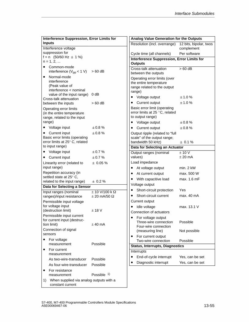
Interface Submodules
13-55S7-400, M7-400 Programmable Controllers Module SpecificationsA5E00069467-06
Interference Suppression, Error Limits forInputsInterference voltagesuppression forf = n (50/60 Hz 1 %)n = 1, 2, ...
• Common-modeinterference (Vpp < 1 V)
• Normal-modeinterference(Peak value ofinterference < nominalvalue of the input range)
Cross-talk attenuationbetween the inputs
> 60 dB
0 dB
> 60 dB
Operating error limits(in the entire temperaturerange, related to the inputrange)
• Voltage input
• Current inputBasic error limits (operatingerror limits at 25° C, relatedto input range)
• Voltage input
• Current input
0.8 %
0.8 %
0.7 %
0.7 %
Linearity error (related toinput range)
0.05 %
Repetition accuracy (insettled state at 25° C,related to the input range) 0.2 %Data for Selecting a SensorInput ranges (nominalranges)/input resistance
± 10 V/100 k ± 20 mA/50
Permissible input voltagefor voltage input(destruction limit) ± 18 VPermissible input currentfor current input (destruc-tion limit) ± 40 mAConnection of signalsensors
• For voltagemeasurement
• For currentmeasurement
Possible
As two-wire-transducer
As four-wire-transducer
• For resistancemeasurement
Possible
Possible
Possible 1)
1) When supplied via analog outputs with a constant current
Analog Value Generation for the OutputsResolution (incl. overrange) 12 bits, bipolar, twos
complement
Cycle time (all channels) Per software
Interference Suppression, Error Limits forOutputsCross-talk attenuationbetween the outputs
> 60 dB
Operating error limits (overthe entire temperaturerange related to the outputrange)
• Voltage output
• Current output
1.0 %
1.0 %Basic error limit (operatingerror limits at 25 C, relatedto output range)
• Voltage output
• Current output
0.8 %
0.8 %
Output ripple (related to “fullscale” of the output range;bandwidth 50 kHz) 0.1 %Data for Selecting an ActuatorOutput ranges (nominalvalues)
± 10 V± 20 mA
Load impedance
• At voltage output
• At current output
• With capacitive load
min. 2 kW
max. 500 W
max. 1.6 mF
Voltage output
• Short-circuit protection
• Short-circuit current
Yes
max. 40 mA
Current output
• Idle voltage max. 13.1 VConnection of actuators
• For voltage outputThree-wire connectionFour-wire connection(measuring line)
• For current outputTwo-wire connection
Possible
Not possible
PossibleStatus, Interrupts, DiagnosticsInterrupts
• End-of-cycle interrupt
• Diagnostic interrupt
Yes, can be set
Yes, can be set
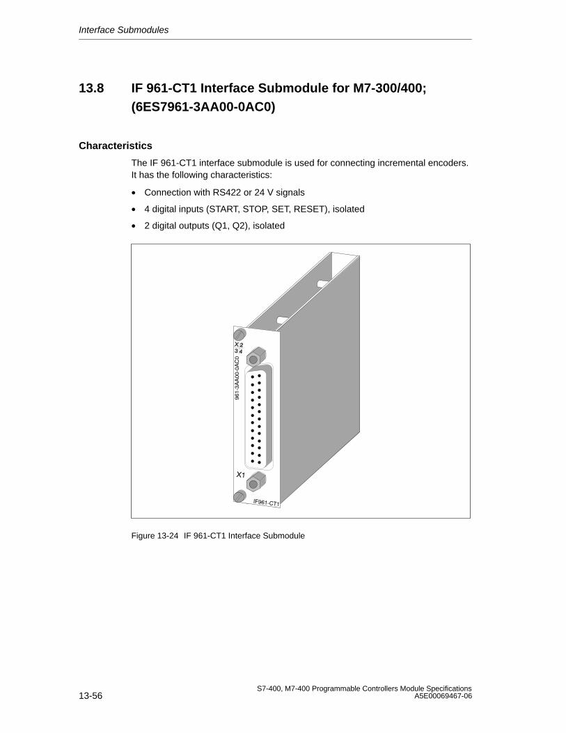
Interface Submodules
13-56S7-400, M7-400 Programmable Controllers Module Specifications
A5E00069467-06
13.8 IF 961-CT1 Interface Submodule for M7-300/400;(6ES7961-3AA00-0AC0)
Characteristics
The IF 961-CT1 interface submodule is used for connecting incremental encoders.It has the following characteristics:
• Connection with RS422 or 24 V signals
• 4 digital inputs (START, STOP, SET, RESET), isolated
• 2 digital outputs (Q1, Q2), isolated
Figure 13-24 IF 961-CT1 Interface Submodule
Interface Submodules
13-57S7-400, M7-400 Programmable Controllers Module SpecificationsA5E00069467-06
13.8.1 What Can the IF961-CT1 Interface Submodule Do?
Introduction
This section contains an overview of the functionality of the IF 961-CT1 interfacesubmodule.
This functionality is achieved using the relevant driver software.
What Can the IF 961-CT1 Interface Submodule Do?
The IF 961-CT1 interface submodule is a high-speed counter module. There is acounter on the submodule that can operate in the following counting ranges:
• 0 to 4 294 967 295 or
• - 2 147 483 648 to + 2 147 483 647.
The maximum input frequency of the counter signals is 500 kHz (5 V) or200 kHz (24V).
You can use the IF 961-CT1 interface submodule for the following counting tasks:
• Endless count
• Single up/down count
• Periodic up/down count
You can start and stop the count either via the user program or via external signals.
Comparison Values
You can store two comparison values on the submodule assigned to the twooutputs of the submodule. If the counter status reaches one of the comparisonvalues, the relevant output can be set to initiate control sequences directly in theprocess.
Initial Value
You can specify an initial value (load value) for the IF 961-CT1. The counter is thenset to the initial value when a signal is present at the 24 V digital input on thesubmodule.
Gate Functions
The count can be started and stopped in dependence on other events via gatefunctions.
The IF 961-CT1 interface submodule has two gate functions:
• A software gate controlled via the program.
• A hardware gate controlled via the digital inputs of the interface submodule.
Interface Submodules
13-58S7-400, M7-400 Programmable Controllers Module Specifications
A5E00069467-06
Interrupts
The IF 961-CT1 can initiate an interrupt when comparison values are reached or inthe event of overflow, underflow, or zero pass of the counter.
Diagnostic Interrupt
The IF 961-CT1 can initiate a diagnostic interrupt for the following events:
• Missing or incorrect counter module parameters
• Hardware interrupt lost
• Signal A, B, or N faulty
Which Signals Can the IF 961-CT1 Count?
The IF 961-CT1 interface submodule can count signals generated by incrementalencoders with 5 V differential signals or with 24 V signals.
The IF 961-CT1 interface submodule can also count 24 V signals generated, forexample, by a light barrier.
Additional Information
You will find more information about the interface submodule IF 961-CT1 in /108/, IF 961-CT1 Counter Function Module, Programming and Parameter AssignmentManual.
Interface Submodules
13-59S7-400, M7-400 Programmable Controllers Module SpecificationsA5E00069467-06
13.8.2 Addressing and Interrupts
Addressing
The IF 961-CT1 interface submodule is addressed with the M7-300/400-reservedI/O address area (starting from C000H).
Addressing in the M7-300/400-Reserved I/O Address Area
The base address depends on the interface submodule slot in the expansionmodule or the programmable module. See the descriptions “M7-300 Expansions”,“M7-400 Expansions” or the description of the M7-400 programmable modules forthe slot-dependent base address of the interface submodule.
Interrupt Request
The interface submodule supplies an interrupt request (IRQa).
You can define the assignment of the IRQa interrupt request to the relevantprocessor interrupt request in the BIOS setup.
Submodule ID
The IF 961-CT1 interface submodule has the submodule ID 03H.
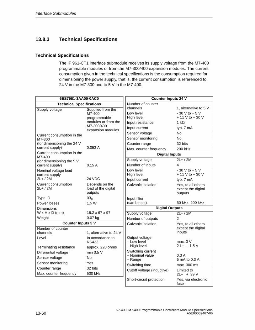
Interface Submodules
13-60S7-400, M7-400 Programmable Controllers Module Specifications
A5E00069467-06
13.8.3 Technical Specifications
Technical Specifications
The IF 961-CT1 interface submodule receives its supply voltage from the M7-400programmable modules or from the M7-300/400 expansion modules. The currentconsumption given in the technical specifications is the consumption required fordimensioning the power supply, that is, the current consumption is referenced to24 V in the M7-300 and to 5 V in the M7-400.
6ES7961-3AA00-0AC0Technical Specifications
Supply voltage Supplied from theM7-400programmablemodules or from theM7-300/400expansion modules
Current consumption in theM7-300(for dimensioning the 24 Vcurrent supply) 0.053 ACurrent consumption in theM7-400(for dimensioning the 5 Vcurrent supply) 0.15 ANominal voltage loadcurrent supply2L+ / 2M 24 VDC
Current consumption2L+ / 2M
Depends on theload of the digitaloutputs
Type ID 03H
Power losses 1.5 WDimensionsW x H x D (mm) 18.2 x 67 x 97Weight 0.07 kg
Counter Inputs 5 VNumber of counterchannels 1, alternative to 24 VLevel In accordance to
RS422Terminating resistance approx. 220 ohmsDifferential voltage min 0.5 VSensor voltage NoSensor monitoring YesCounter range 32 bitsMax. counter frequency 500 kHz
Counter Inputs 24 VNumber of counterchannels 1, alternative to 5 VLow levelHigh level
- 30 V to + 5 V+ 11 V to + 30 V
Input resistance 1 kInput current typ. 7 mASensor voltage NoSensor monitoring NoCounter range 32 bitsMax. counter frequency 200 kHz
Digital InputsSupply voltage 2L+ / 2MNumber of inputs 4Low levelHigh level
- 30 V to + 5 V+ 11 V to + 30 V
Input current typ. 7 mAGalvanic isolation Yes, to all others
except the digitaloutputs
Input filter(can be set) 50 kHz, 200 kHz
Digital OutputsSupply voltage 2L+ / 2MNumber of outputs 2Galvanic isolation Yes, to all others
except the digitalinputs
Output voltage– Low level– High level
max. 3 V2 L+ - 1.5 V
Switching current– Nominal value– Range
0.3 A5 mA to 0.3 A
Switching time max. 300 msCutoff voltage (inductive) Limited to
2L+ + 39 VShort-circuit protection Yes, via electronic
fuse
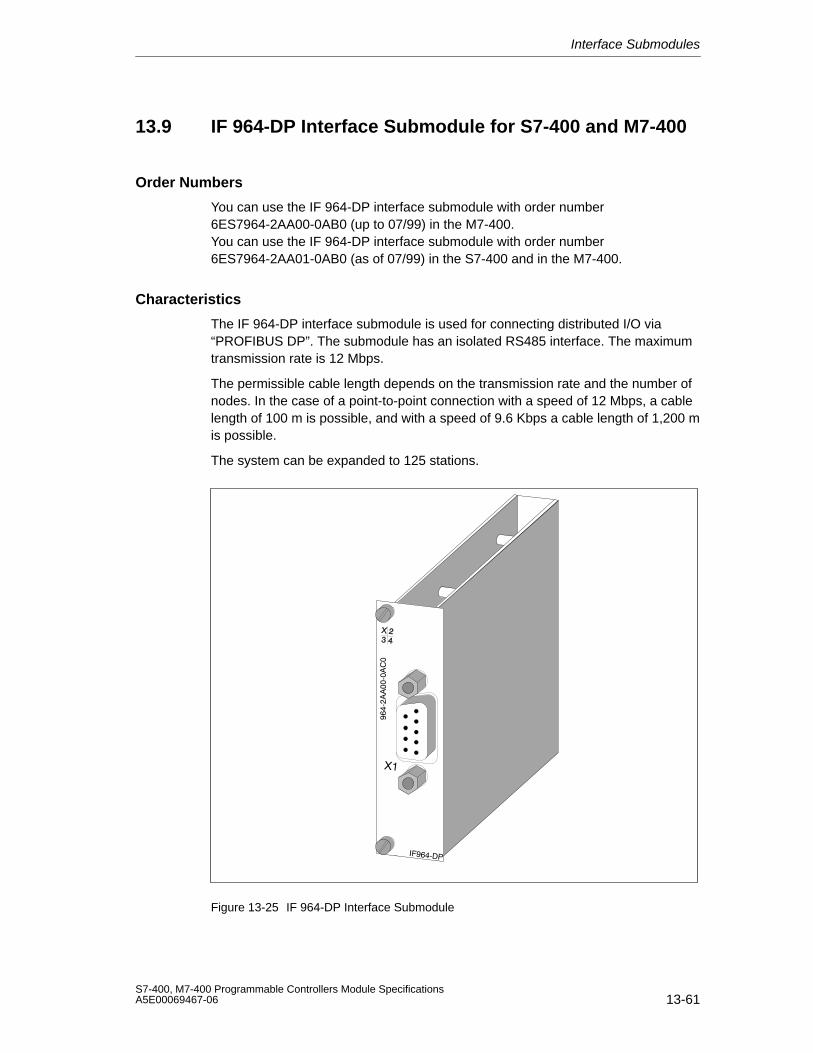
Interface Submodules
13-61S7-400, M7-400 Programmable Controllers Module SpecificationsA5E00069467-06
13.9 IF 964-DP Interface Submodule for S7-400 and M7-400
Order Numbers
You can use the IF 964-DP interface submodule with order number6ES7964-2AA00-0AB0 (up to 07/99) in the M7-400.You can use the IF 964-DP interface submodule with order number6ES7964-2AA01-0AB0 (as of 07/99) in the S7-400 and in the M7-400.
Characteristics
The IF 964-DP interface submodule is used for connecting distributed I/O via“PROFIBUS DP”. The submodule has an isolated RS485 interface. The maximumtransmission rate is 12 Mbps.
The permissible cable length depends on the transmission rate and the number ofnodes. In the case of a point-to-point connection with a speed of 12 Mbps, a cablelength of 100 m is possible, and with a speed of 9.6 Kbps a cable length of 1,200 mis possible.
The system can be expanded to 125 stations.
Figure 13-25 IF 964-DP Interface Submodule
Interface Submodules
13-62S7-400, M7-400 Programmable Controllers Module Specifications
A5E00069467-06
Additional Front Cover
The IF 964-DP interface submodule with order number 6ES7964-2AA01-0AB0 hasan additional front cover, which is similar to the front cover of the IF 960HFsynchronization submodule. As long as this second front cover is not screwed on,the submodule interface on the S7-400 CPU remains off circuit. Only when youinsert an IF submodule and screw on the second front cover, is the submoduleinterface on circuit.
When using the submodule in an M7 the additional front cover has no function, itshould, however, be mounted for technical maintenance reasons and due toimproved EMC properties.
Note
Even in an S7-400 CPU you may remove or insert the IF 964-DP interfacesubmodule only if it is off circuit.
If you remove the front cover of the interface submodule while the power supply isswitched on, the CPU goes into DEFECTIVE mode.
Additional Information
You can find information on “PROFIBUS DP” in the following technical overviews ormanuals:
• Technical overview Distributed I/O in SIMATIC S7 and M7
• Manuals on the DP masters, for example, S7-300 Programmable Controller orS7-400, M7-400 Programmable Controllers for the PROFIBUS-DP interface ofthe S7-300
• Manuals on the DP slaves, for example, ET 200M Distributed I/O Device orET 200C Distributed I/O Device
• The manual on the network components SINEC L2/L2FO Network Manual,such as bus connectors, RS 485 repeaters
• Manuals on STEP 7
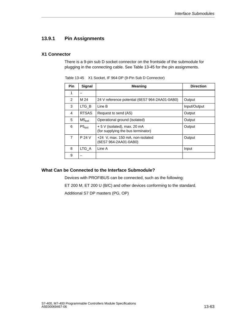
Interface Submodules
13-63S7-400, M7-400 Programmable Controllers Module SpecificationsA5E00069467-06
13.9.1 Pin Assignments
X1 Connector
There is a 9-pin sub D socket connector on the frontside of the submodule forplugging in the connecting cable. See Table 13-45 for the pin assignments.
Table 13-45 X1 Socket, IF 964-DP (9-Pin Sub D Connector)
Pin Signal Meaning Direction
1 –
2 M 24 24 V reference potential (6ES7 964-2AA01-0AB0) Output
3 LTG_B Line B Input/Output
4 RTSAS Request to send (AS) Output
5 M5ext Operational ground (isolated) Output
6 P5ext + 5 V (isolated), max. 20 mA(for supplying the bus terminator)
Output
7 P 24 V +24 V, max. 150 mA, non-isolated(6ES7 964-2AA01-0AB0)
Output
8 LTG_A Line A Input
9 –
What Can be Connected to the Interface Submodule?
Devices with PROFIBUS can be connected, such as the following:
ET 200 M, ET 200 U (B/C) and other devices conforming to the standard.
Additional S7 DP masters (PG, OP)
Interface Submodules
13-64S7-400, M7-400 Programmable Controllers Module Specifications
A5E00069467-06
13.9.2 Addressing and Interrupts
In the M7-300/400-Reserved I/O Address Area
The base address depends on the interface submodule slot in the expansionmodule or the programmable module. See the descriptions “M7-300 Expansions”,“M7-400 Expansions” or the description of the M7-400 programmable modules forthe slot-dependent base address of the interface submodule.
You require the base address for assigning parameters to the driver software.
Intermediate Memory
The IF 964-DP interface submodule provides (intermediate) storage of the data inthe dual-port RAM. The size of the memory and its address can be assigned viathe driver used.
Protected Mode: 1 out of 8 areas of 512 Kbytes in the address areaC0 00 00H bis FF FF FFH.
Note
The memory address must not collide with other system addresses. TheIF 964-VGA interface submodule, for example, occupies the addresses fromC 00 00H to C 7F FFH.
Interrupt Request
The interrupt line of the interface submodule is switched with a processor interruptper software parameter assignment.
Addressing in the S7-400 I/O Address Area
The interface submodule can be accessed by the respective interface in anassigned address window.
Interrupt Request
The interrupt line of the interface submodule is permanently assigned to theprocessor interrupt.
Submodule ID
The IF 964-DP interface submodule has the submodule ID 8CH.
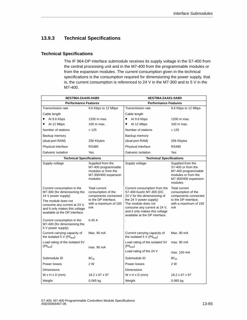
Interface Submodules
13-65S7-400, M7-400 Programmable Controllers Module SpecificationsA5E00069467-06
13.9.3 Technical Specifications
Technical Specifications
The IF 964-DP interface submodule receives its supply voltage in the S7-400 fromthe central processing unit and in the M7-400 from the programmable modules orfrom the expansion modules. The current consumption given in the technicalspecifications is the consumption required for dimensioning the power supply, thatis, the current consumption is referenced to 24 V in the M7-300 and to 5 V in theM7-400.
6ES7964-2AA00-0AB0 6ES7964-2AA01-0AB0
Performance Features Performance Features
Transmission rate 9.6 Kbps to 12 Mbps Transmission rate 9.6 Kbps to 12 Mbps
Cable length
• At 9.6 Kbps
• At 12 Mbps
1200 m max.
100 m max.
Cable length
• At 9.6 Kbps
• At 12 Mbps
1200 m max.
100 m max.
Number of stations ≤ 125 Number of stations ≤ 125
Backup memory
(dual-port RAM) 256 Kbytes
Backup memory
(dual-port RAM) 256 Kbytes
Physical interface RS485 Physical interface RS485
Galvanic isolation Yes Galvanic isolation Yes
Technical Specifications Technical Specifications
Supply voltage Supplied from theM7-400 programmablemodules or from theM7-300/400 expansionmodules
Supply voltage Supplied from theS7-400 or from theM7-400 programmablemodules or from theM7-300/400 expansionmodules
Current consumption in theM7-300 (for dimensioning the24 V power supply)
The module does notconsume any current at 24 V,and it only makes this voltageavailable at the DP interface.
Total currentconsumption of thecomponents connectedto the DP interface,with a maximum of 150mA
Current consumption from theS7-400 bus/in M7-300 (DC24 V for the dimensioning ofthe 24 V power supply)The module does notconsume any current at 24 V,and it only makes this voltageavailable at the DP interface.
Total currentconsumption of thecomponents connectedto the DP interface,with a maximum of 150mA
Current consumption in theM7-400 (for dimensioning the5 V power supply)
0.45 A .
Current carrying capacity ofthe isolated 5 V (P5ext)
Max. 90 mA Current carrying capacity ofthe isolated 5 V (P5ext)
Max. 90 mA
Load rating of the isolated 5V(P5ext) max. 90 mA
Load rating of the isolated 5V(P5ext)
Load rating of the 24 V
max. 90 mA
max. 150 mA
Submodule ID 8CH Submodule ID 8CH
Power losses 2 W Power losses 2 W
Dimensions
W x H x D (mm) 18.2 x 67 x 97
Dimensions
W x H x D (mm) 18.2 x 67 x 97
Weight 0.065 kg Weight 0.065 kg

Interface Submodules
13-66S7-400, M7-400 Programmable Controllers Module Specifications
A5E00069467-06
A-1S7-400, M7-400 Programmable Controllers Module SpecificationsA5E00069467-06
Parameter Sets for Signal Modules
Chapter Overview
Section Description Page
A.1 How to Assign the Parameters for Signal Modules in the User Program
A-2
A.2 Parameters of the Digital Input Modules A-4
A.3 Parameters of the Digital Output Modules A-7
A.4 Parameters of the Analog Input Modules A-10
A
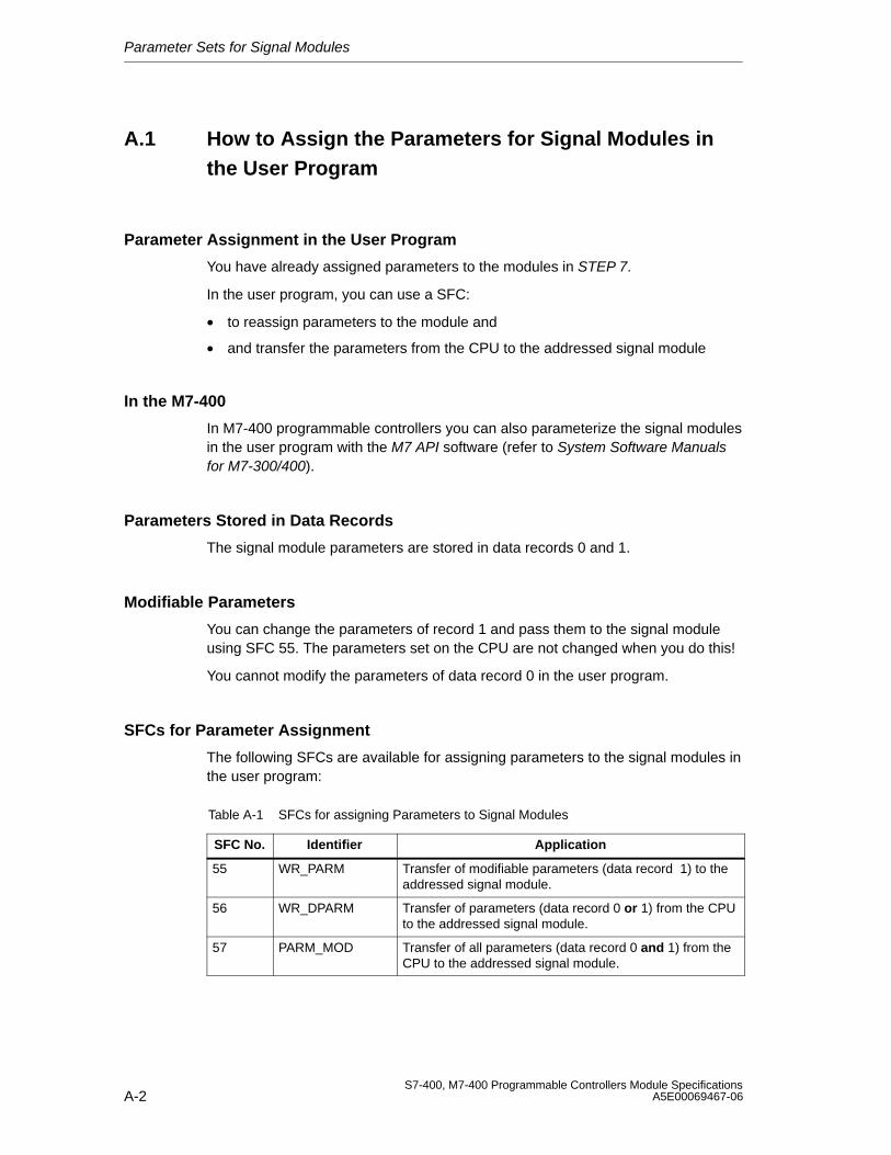
Parameter Sets for Signal Modules
A-2S7-400, M7-400 Programmable Controllers Module Specifications
A5E00069467-06
A.1 How to Assign the Parameters for Signal Modules inthe User Program
Parameter Assignment in the User Program
You have already assigned parameters to the modules in STEP 7.
In the user program, you can use a SFC:
• to reassign parameters to the module and
• and transfer the parameters from the CPU to the addressed signal module
In the M7-400
In M7-400 programmable controllers you can also parameterize the signal modulesin the user program with the M7 API software (refer to System Software Manualsfor M7-300/400).
Parameters Stored in Data Records
The signal module parameters are stored in data records 0 and 1.
Modifiable Parameters
You can change the parameters of record 1 and pass them to the signal moduleusing SFC 55. The parameters set on the CPU are not changed when you do this!
You cannot modify the parameters of data record 0 in the user program.
SFCs for Parameter Assignment
The following SFCs are available for assigning parameters to the signal modules inthe user program:
Table A-1 SFCs for assigning Parameters to Signal Modules
SFC No. Identifier Application
55 WR_PARM Transfer of modifiable parameters (data record 1) to theaddressed signal module.
56 WR_DPARM Transfer of parameters (data record 0 or 1) from the CPUto the addressed signal module.
57 PARM_MOD Transfer of all parameters (data record 0 and 1) from theCPU to the addressed signal module.
Parameter Sets for Signal Modules
A-3S7-400, M7-400 Programmable Controllers Module SpecificationsA5E00069467-06
Description of the Parameters
The following sections contain all the modifiable parameters for the various moduleclasses. The parameters of the signal modules are described:
• in the online help of STEP 7.
• in this reference manual
You will find the parameters that can be adjusted for the signal moduleconcerned in the specific sections for the different signal modules.
Further References
You can find an in-depth description of the principle of assigning parameters tosignal modules in the user program and a description of the SFCs that can be usedfor this purpose in the STEP 7 manuals.
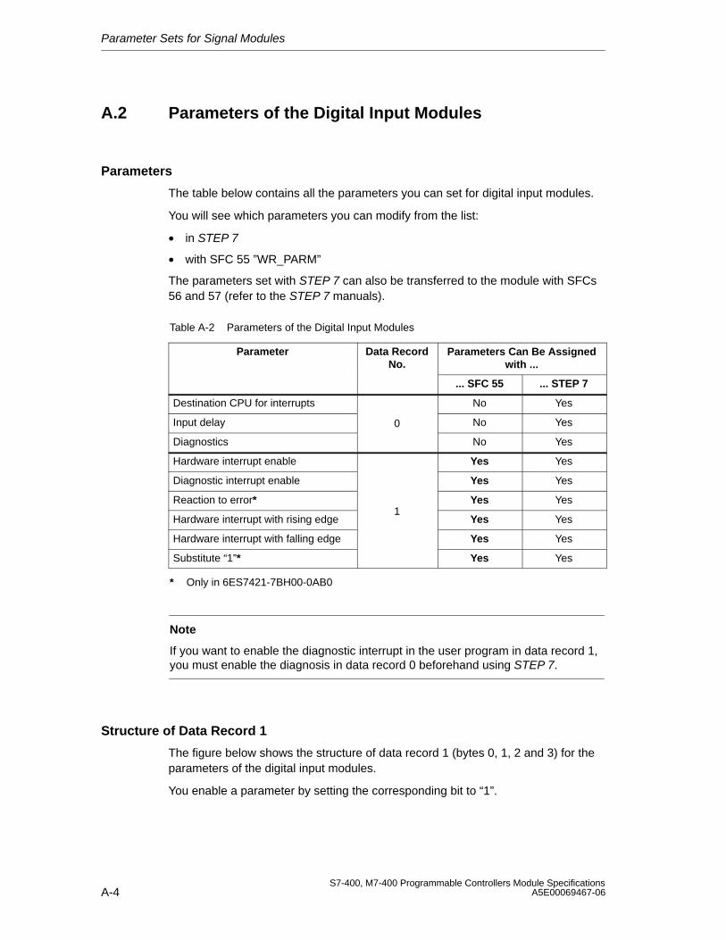
Parameter Sets for Signal Modules
A-4S7-400, M7-400 Programmable Controllers Module Specifications
A5E00069467-06
A.2 Parameters of the Digital Input Modules
Parameters
The table below contains all the parameters you can set for digital input modules.
You will see which parameters you can modify from the list:
• in STEP 7
• with SFC 55 ”WR_PARM”
The parameters set with STEP 7 can also be transferred to the module with SFCs56 and 57 (refer to the STEP 7 manuals).
Table A-2 Parameters of the Digital Input Modules
Parameter Data RecordNo.
Parameters Can Be Assignedwith ...
... SFC 55 ... STEP 7
Destination CPU for interrupts No Yes
Input delay 0 No Yes
Diagnostics No Yes
Hardware interrupt enable Yes Yes
Diagnostic interrupt enable Yes Yes
Reaction to error* Yes Yes
Hardware interrupt with rising edge1
Yes Yes
Hardware interrupt with falling edge Yes Yes
Substitute “1”* Yes Yes
* Only in 6ES7421-7BH00-0AB0
Note
If you want to enable the diagnostic interrupt in the user program in data record 1,you must enable the diagnosis in data record 0 beforehand using STEP 7.
Structure of Data Record 1
The figure below shows the structure of data record 1 (bytes 0, 1, 2 and 3) for theparameters of the digital input modules.
You enable a parameter by setting the corresponding bit to “1”.
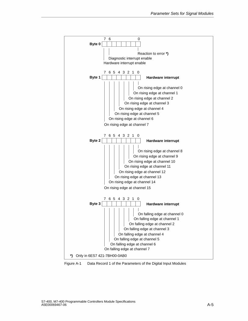
Parameter Sets for Signal Modules
A-5S7-400, M7-400 Programmable Controllers Module SpecificationsA5E00069467-06
Byte 07 6 0
Hardware interrupt enableDiagnostic interrupt enable
Byte 17 6 0
On rising edge at channel 0
On rising edge at channel 2
On rising edge at channel 4
On rising edge at channel 6
5 4 3 2 1Hardware interrupt
On rising edge at channel 1
On rising edge at channel 3
On rising edge at channel 5
On rising edge at channel 7
Byte 27 6 0
On rising edge at channel 8
On rising edge at channel 10
On rising edge at channel 12
On rising edge at channel 14
5 4 3 2 1
Hardware interrupt
On rising edge at channel 9
On rising edge at channel 11
On rising edge at channel 13
On rising edge at channel 15
Reaction to error *)
Byte 37 6 0
On falling edge at channel 1
On falling edge at channel 3
On falling edge at channel 5
On falling edge at channel 7
5 4 3 2 1
Hardware interrupt
On falling edge at channel 0
On falling edge at channel 2
On falling edge at channel 4
On falling edge at channel 6
*) Only in 6ES7 421-7BH00-0AB0
Figure A-1 Data Record 1 of the Parameters of the Digital Input Modules
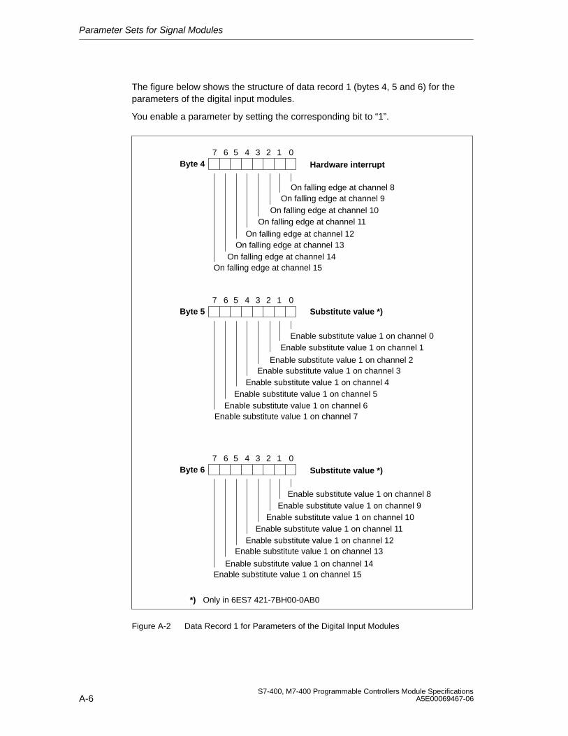
Parameter Sets for Signal Modules
A-6S7-400, M7-400 Programmable Controllers Module Specifications
A5E00069467-06
The figure below shows the structure of data record 1 (bytes 4, 5 and 6) for theparameters of the digital input modules.
You enable a parameter by setting the corresponding bit to “1”.
Byte 47 6 0
On falling edge at channel 9
On falling edge at channel 11
On falling edge at channel 13
On falling edge at channel 15
5 4 3 2 1
Hardware interrupt
On falling edge at channel 8
On falling edge at channel 10
On falling edge at channel 12
On falling edge at channel 14
Byte 57 6 05 4 3 2 1
Byte 67 6 0
Enable substitute value 1 on channel 15
5 4 3 2 1
Substitute value *)
Substitute value *)
Enable substitute value 1 on channel 7Enable substitute value 1 on channel 6
Enable substitute value 1 on channel 5Enable substitute value 1 on channel 4
Enable substitute value 1 on channel 3Enable substitute value 1 on channel 2
Enable substitute value 1 on channel 1Enable substitute value 1 on channel 0
Enable substitute value 1 on channel 8Enable substitute value 1 on channel 9
Enable substitute value 1 on channel 10Enable substitute value 1 on channel 11
Enable substitute value 1 on channel 12Enable substitute value 1 on channel 13
Enable substitute value 1 on channel 14
*) Only in 6ES7 421-7BH00-0AB0
Figure A-2 Data Record 1 for Parameters of the Digital Input Modules
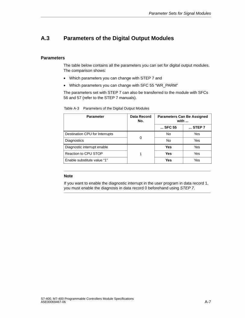
Parameter Sets for Signal Modules
A-7S7-400, M7-400 Programmable Controllers Module SpecificationsA5E00069467-06
A.3 Parameters of the Digital Output Modules
Parameters
The table below contains all the parameters you can set for digital output modules.The comparison shows:
• Which parameters you can change with STEP 7 and
• Which parameters you can change with SFC 55 “WR_PARM”
The parameters set with STEP 7 can also be transferred to the module with SFCs56 and 57 (refer to the STEP 7 manuals).
Table A-3 Parameters of the Digital Output Modules
Parameter Data RecordNo.
Parameters Can Be Assignedwith ...
... SFC 55 ... STEP 7
Destination CPU for Interrupts No Yes
Diagnostics0
No Yes
Diagnostic interrupt enable Yes Yes
Reaction to CPU STOP 1 Yes Yes
Enable substitute value “1” Yes Yes
Note
If you want to enable the diagnostic interrupt in the user program in data record 1,you must enable the diagnosis in data record 0 beforehand using STEP 7.
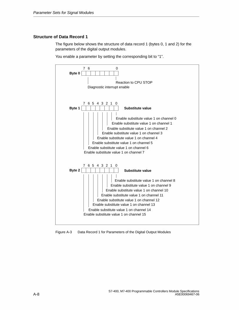
Parameter Sets for Signal Modules
A-8S7-400, M7-400 Programmable Controllers Module Specifications
A5E00069467-06
Structure of Data Record 1
The figure below shows the structure of data record 1 (bytes 0, 1 and 2) for theparameters of the digital output modules.
You enable a parameter by setting the corresponding bit to “1”.
Byte 07 6 0
Diagnostic interrupt enableReaction to CPU STOP
Byte 17 6 05 4 3 2 1
Byte 27 6 0
Enable substitute value 1 on channel 15
5 4 3 2 1
Substitute value
Substitute value
Enable substitute value 1 on channel 7Enable substitute value 1 on channel 6
Enable substitute value 1 on channel 5Enable substitute value 1 on channel 4
Enable substitute value 1 on channel 3Enable substitute value 1 on channel 2
Enable substitute value 1 on channel 1Enable substitute value 1 on channel 0
Enable substitute value 1 on channel 8Enable substitute value 1 on channel 9
Enable substitute value 1 on channel 10Enable substitute value 1 on channel 11
Enable substitute value 1 on channel 12Enable substitute value 1 on channel 13
Enable substitute value 1 on channel 14
Figure A-3 Data Record 1 for Parameters of the Digital Output Modules
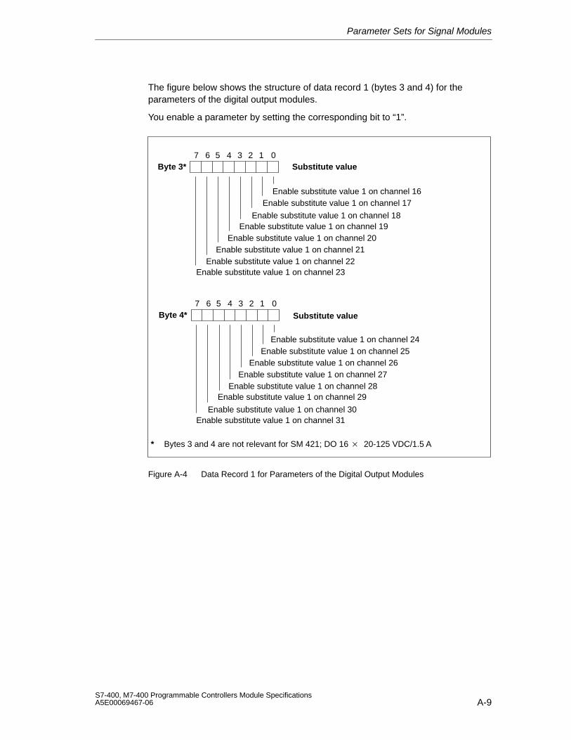
Parameter Sets for Signal Modules
A-9S7-400, M7-400 Programmable Controllers Module SpecificationsA5E00069467-06
The figure below shows the structure of data record 1 (bytes 3 and 4) for theparameters of the digital output modules.
You enable a parameter by setting the corresponding bit to “1”.
Byte 3*7 6 05 4 3 2 1
Byte 4*7 6 0
Enable substitute value 1 on channel 31
5 4 3 2 1
Substitute value
Substitute value
Enable substitute value 1 on channel 23Enable substitute value 1 on channel 22
Enable substitute value 1 on channel 21Enable substitute value 1 on channel 20
Enable substitute value 1 on channel 19Enable substitute value 1 on channel 18
Enable substitute value 1 on channel 17Enable substitute value 1 on channel 16
Enable substitute value 1 on channel 24Enable substitute value 1 on channel 25
Enable substitute value 1 on channel 26Enable substitute value 1 on channel 27
Enable substitute value 1 on channel 28Enable substitute value 1 on channel 29
Enable substitute value 1 on channel 30
* Bytes 3 and 4 are not relevant for SM 421; DO 16 20-125 VDC/1.5 A
Figure A-4 Data Record 1 for Parameters of the Digital Output Modules
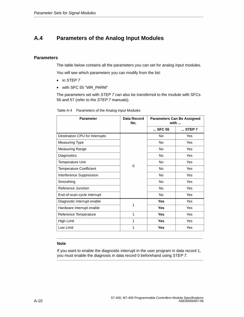
Parameter Sets for Signal Modules
A-10S7-400, M7-400 Programmable Controllers Module Specifications
A5E00069467-06
A.4 Parameters of the Analog Input Modules
Parameters
The table below contains all the parameters you can set for analog input modules.
You will see which parameters you can modify from the list:
• in STEP 7
• with SFC 55 ”WR_PARM”
The parameters set with STEP 7 can also be transferred to the module with SFCs56 and 57 (refer to the STEP 7 manuals).
Table A-4 Parameters of the Analog Input Modules
Parameter Data RecordNo.
Parameters Can Be Assignedwith ...
... SFC 55 ... STEP 7
Destination CPU for Interrupts No Yes
Measuring Type No Yes
Measuring Range No Yes
Diagnostics No Yes
Temperature Unit No Yes
Temperature Coefficient0
No Yes
Interference Suppression No Yes
Smoothing No Yes
Reference Junction No Yes
End-of-scan-cycle interrupt No Yes
Diagnostic interrupt enable Yes Yes
Hardware interrupt enable1
Yes Yes
Reference Temperature 1 Yes Yes
High Limit 1 Yes Yes
Low Limit 1 Yes Yes
Note
If you want to enable the diagnostic interrupt in the user program in data record 1,you must enable the diagnosis in data record 0 beforehand using STEP 7.
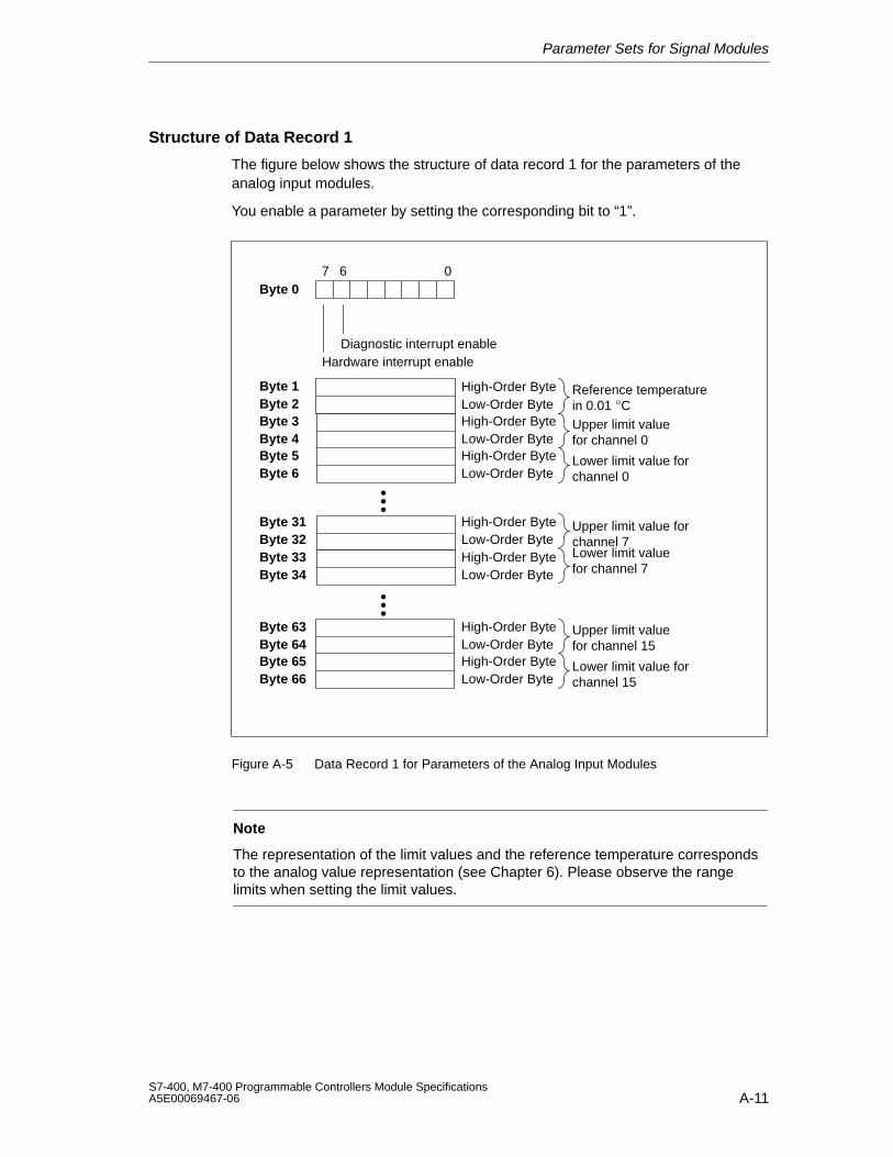
Parameter Sets for Signal Modules
A-11S7-400, M7-400 Programmable Controllers Module SpecificationsA5E00069467-06
Structure of Data Record 1
The figure below shows the structure of data record 1 for the parameters of theanalog input modules.
You enable a parameter by setting the corresponding bit to “1”.
Byte 07 6 0
Diagnostic interrupt enableHardware interrupt enable
Upper limit valuefor channel 15
Lower limit value forchannel 15
Low-Order Byte
Low-Order Byte
High-Order Byte
High-Order Byte
Byte 63Byte 64Byte 65Byte 66
Upper limit valuefor channel 0
Lower limit value forchannel 0
Upper limit value forchannel 7Lower limit valuefor channel 7
Low-Order Byte
Low-Order Byte
Low-Order Byte
Low-Order Byte
High-Order Byte
High-Order Byte
High-Order Byte
High-Order Byte
Byte 3Byte 4Byte 5Byte 6
Byte 31Byte 32Byte 33Byte 34
Byte 1Byte 2
Reference temperaturein 0.01 CLow-Order Byte
High-Order Byte
•••
•••
Figure A-5 Data Record 1 for Parameters of the Analog Input Modules
Note
The representation of the limit values and the reference temperature correspondsto the analog value representation (see Chapter 6). Please observe the rangelimits when setting the limit values.

Parameter Sets for Signal Modules
A-12S7-400, M7-400 Programmable Controllers Module Specifications
A5E00069467-06
B-1S7-400, M7-400 Programmable Controllers Module SpecificationsA5E00069467-06
Diagnostic Data of the Signal Modules
Chapter Overview
Section Description Page
B.1 Evaluating the Diagnostic Data of the Signal Modules in the UserProgram
B-2
B.2 Structure and Contents of Diagnostic Data Bytes 0 and 1 B-3
B.3 Diagnostic Data of the Digital Input Modules as of Byte 2 B-4
B.4 Diagnostic Data of the Digital Output Modules as of Byte 2 B-8
B.5 Diagnostic Data of the Analog Input Modules as of Byte 2 B-14
B
Diagnostic Data of the Signal Modules
B-2S7-400, M7-400 Programmable Controllers Module Specifications
A5E00069467-06
B.1 Evaluating the Diagnostic Data of the Signal Modulesin the User Program
In This Appendix
This Appendix describes the structure of the diagnostic data in the system data.You must be familiar with this structure if you want to evaluate the diagnostic dataof the signal module in the STEP 7 user program.
Diagnostic Data are Contained in Data Records
The diagnostic data of a module can be up to 43 bytes long and are contained indata records 0 and 1:
• Data record 0 contains 4 bytes of diagnostic data that describe the currentstatus of a programmable controller.
• Data record 1 contains the four bytes of diagnostic data that are also containedin data record 0 and as many as 39 bytes of module-specific diagnostic data.
Further Reading
An in-depth description of the principle of evaluating the diagnostic data of signalmodules in the user program and a description of the SFCs that can be used forthat purpose will be found in the STEP 7 manuals.
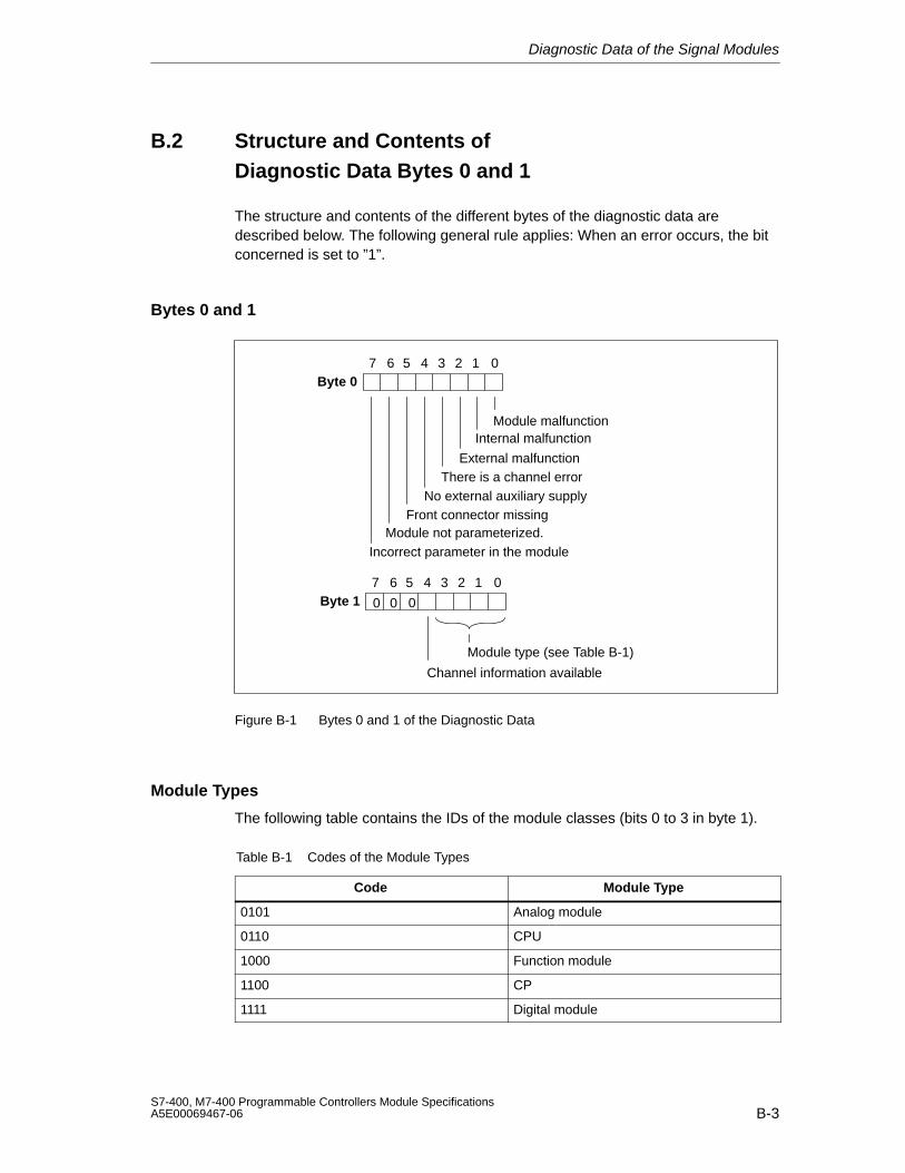
Diagnostic Data of the Signal Modules
B-3S7-400, M7-400 Programmable Controllers Module SpecificationsA5E00069467-06
B.2 Structure and Contents of Diagnostic Data Bytes 0 and 1
The structure and contents of the different bytes of the diagnostic data aredescribed below. The following general rule applies: When an error occurs, the bitconcerned is set to ”1”.
Bytes 0 and 1
Byte 07 6 0
Module malfunctionInternal malfunction
External malfunctionThere is a channel error
No external auxiliary supplyFront connector missing
Module not parameterized.Incorrect parameter in the module
5 4 3 2 1
Byte 17 6 0
Channel information available
5 4 3 2 1
Module type (see Table B-1)
00 0
Figure B-1 Bytes 0 and 1 of the Diagnostic Data
Module Types
The following table contains the IDs of the module classes (bits 0 to 3 in byte 1).
Table B-1 Codes of the Module Types
Code Module Type
0101 Analog module
0110 CPU
1000 Function module
1100 CP
1111 Digital module
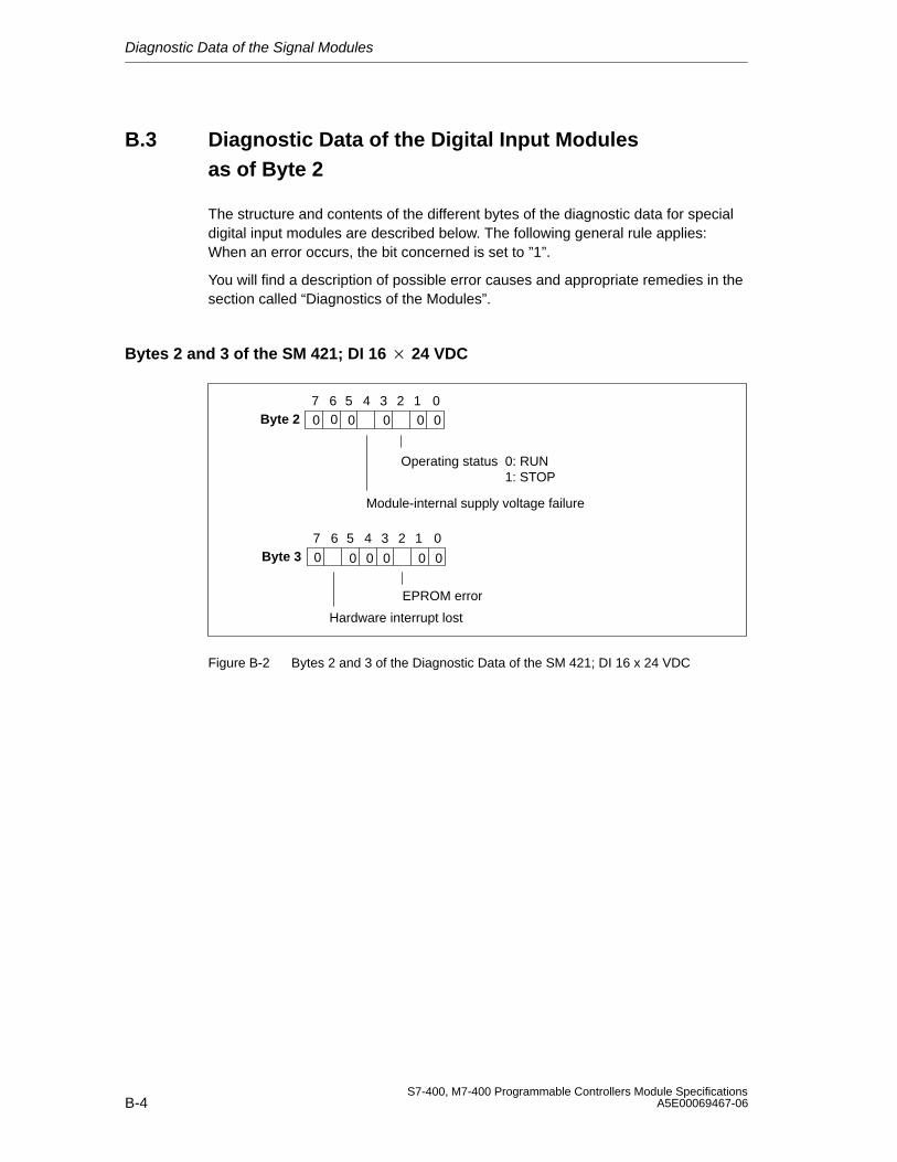
Diagnostic Data of the Signal Modules
B-4S7-400, M7-400 Programmable Controllers Module Specifications
A5E00069467-06
B.3 Diagnostic Data of the Digital Input Modules as of Byte 2
The structure and contents of the different bytes of the diagnostic data for specialdigital input modules are described below. The following general rule applies:When an error occurs, the bit concerned is set to ”1”.
You will find a description of possible error causes and appropriate remedies in thesection called “Diagnostics of the Modules”.
Bytes 2 and 3 of the SM 421; DI 16 24 VDC
Byte 27 6 0
Operating status 0: RUN1: STOP
Module-internal supply voltage failure
5 4 3 2 1
0
Byte 37 6 0
EPROM error
Hardware interrupt lost
5 4 3 2 1
0
00 0 0 0
0 0 0 0 0
Figure B-2 Bytes 2 and 3 of the Diagnostic Data of the SM 421; DI 16 x 24 VDC
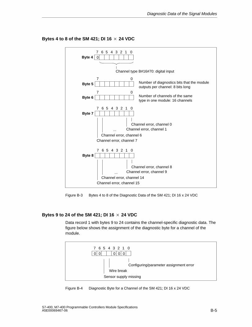
Diagnostic Data of the Signal Modules
B-5S7-400, M7-400 Programmable Controllers Module SpecificationsA5E00069467-06
Bytes 4 to 8 of the SM 421; DI 16 24 VDC
Byte 47 6 05 4 3 2 1
Byte 57 0
Channel type B#16#70: digital input
Number of diagnostics bits that the moduleoutputs per channel: 8 bits long
Byte 67 0
Number of channels of the sametype in one module: 16 channels
Byte 77 6 0
Channel error, channel 0Channel error, channel 1
Channel error, channel 6Channel error, channel 7
5 4 3 2 1
...
0
Byte 87 6 0
Channel error, channel 14Channel error, channel 15
5 4 3 2 1
...
Channel error, channel 8Channel error, channel 9
Figure B-3 Bytes 4 to 8 of the Diagnostic Data of the SM 421; DI 16 x 24 VDC
Bytes 9 to 24 of the SM 421; DI 16 24 VDC
Data record 1 with bytes 9 to 24 contains the channel-specific diagnostic data. Thefigure below shows the assignment of the diagnostic byte for a channel of themodule.
7 6 0
Sensor supply missing
5 4 3 2 1
00
Configuring/parameter assignment error
Wire break
0 0 0
Figure B-4 Diagnostic Byte for a Channel of the SM 421; DI 16 x 24 VDC
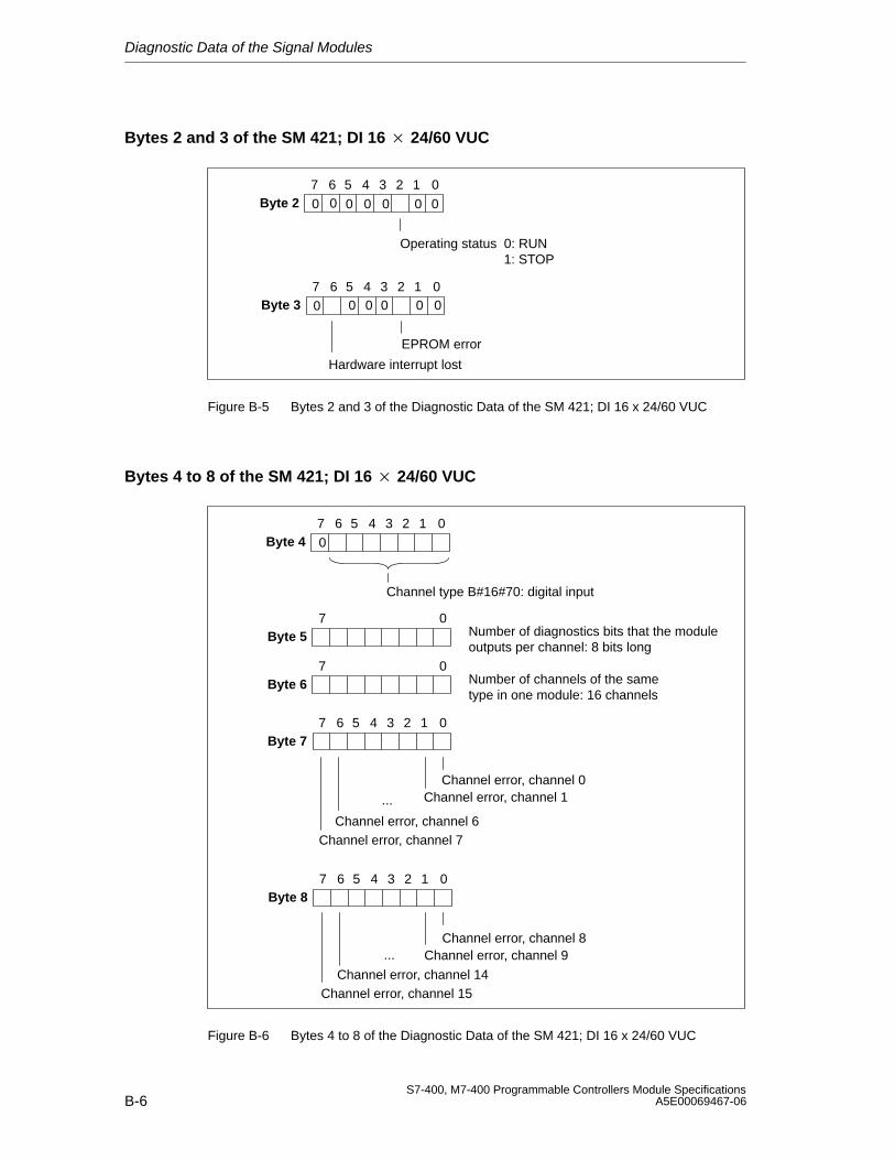
Diagnostic Data of the Signal Modules
B-6S7-400, M7-400 Programmable Controllers Module Specifications
A5E00069467-06
Bytes 2 and 3 of the SM 421; DI 16 24/60 VUC
Byte 27 6 0
Operating status 0: RUN1: STOP
5 4 3 2 1
0
Byte 37 6 0
EPROM error
Hardware interrupt lost
5 4 3 2 10
0 0 0 0 0 0
0 0 0 0 0
Figure B-5 Bytes 2 and 3 of the Diagnostic Data of the SM 421; DI 16 x 24/60 VUC
Bytes 4 to 8 of the SM 421; DI 16 24/60 VUC
Byte 47 6 05 4 3 2 1
Byte 57 0
Channel type B#16#70: digital input
Number of diagnostics bits that the moduleoutputs per channel: 8 bits long
Byte 67 0
Number of channels of the sametype in one module: 16 channels
Byte 77 6 0
Channel error, channel 0Channel error, channel 1
Channel error, channel 6Channel error, channel 7
5 4 3 2 1
...
0
Byte 87 6 0
Channel error, channel 14Channel error, channel 15
5 4 3 2 1
...Channel error, channel 8
Channel error, channel 9
Figure B-6 Bytes 4 to 8 of the Diagnostic Data of the SM 421; DI 16 x 24/60 VUC
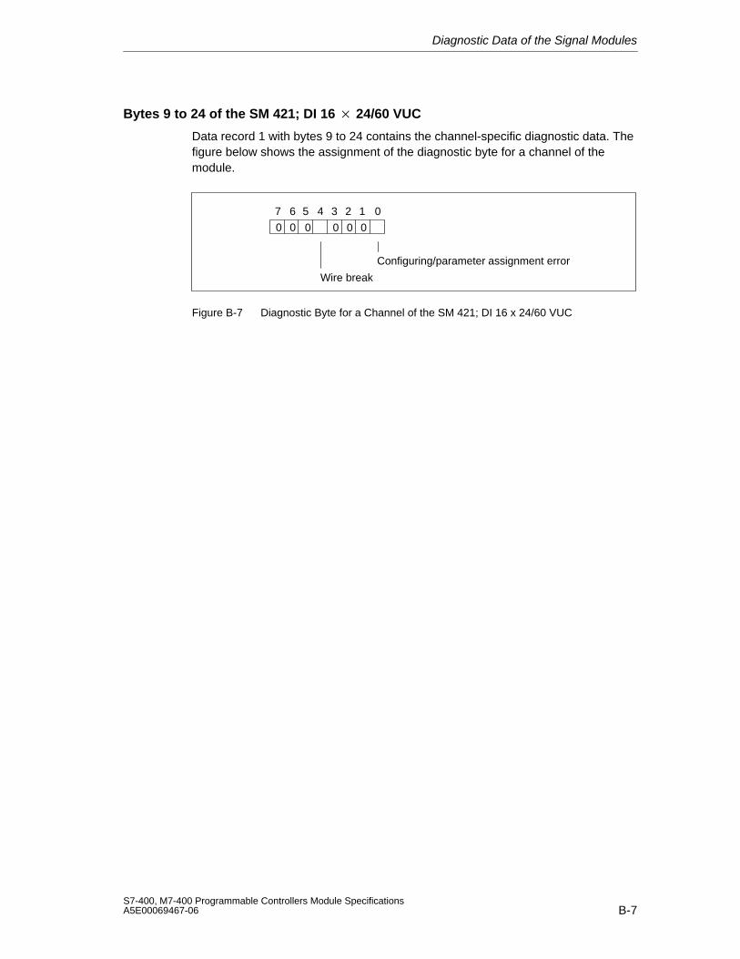
Diagnostic Data of the Signal Modules
B-7S7-400, M7-400 Programmable Controllers Module SpecificationsA5E00069467-06
Bytes 9 to 24 of the SM 421; DI 16 24/60 VUC
Data record 1 with bytes 9 to 24 contains the channel-specific diagnostic data. Thefigure below shows the assignment of the diagnostic byte for a channel of themodule.
7 6 05 4 3 2 1
00
Configuring/parameter assignment error
Wire break
0 0 00
Figure B-7 Diagnostic Byte for a Channel of the SM 421; DI 16 x 24/60 VUC
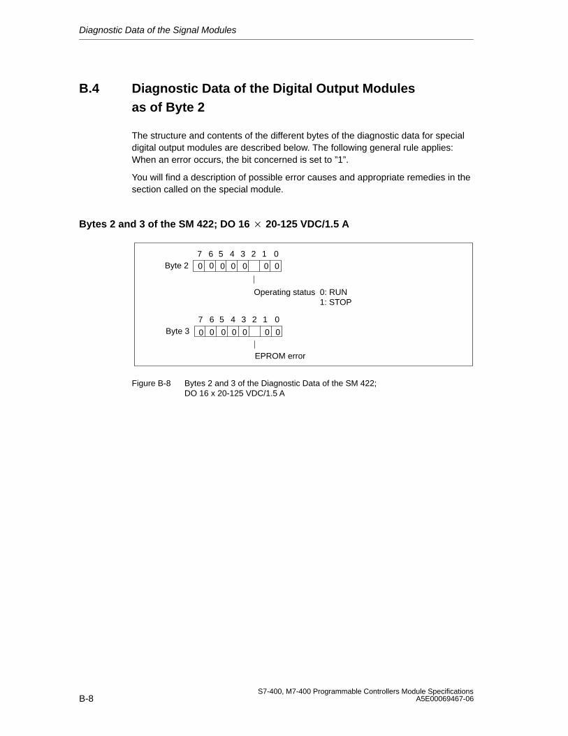
Diagnostic Data of the Signal Modules
B-8S7-400, M7-400 Programmable Controllers Module Specifications
A5E00069467-06
B.4 Diagnostic Data of the Digital Output Modules as of Byte 2
The structure and contents of the different bytes of the diagnostic data for specialdigital output modules are described below. The following general rule applies:When an error occurs, the bit concerned is set to ”1”.
You will find a description of possible error causes and appropriate remedies in thesection called on the special module.
Bytes 2 and 3 of the SM 422; DO 16 20-125 VDC/1.5 A
Byte 27 6 0
Operating status 0: RUN1: STOP
5 4 3 2 1
0
Byte 37 6 0
EPROM error
5 4 3 2 1
0
00 0 0 0
0 0 0 0 00
0
Figure B-8 Bytes 2 and 3 of the Diagnostic Data of the SM 422;DO 16 x 20-125 VDC/1.5 A
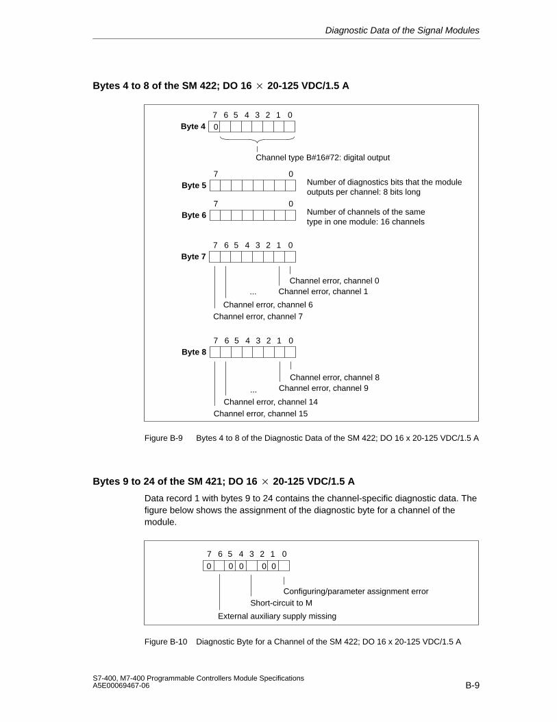
Diagnostic Data of the Signal Modules
B-9S7-400, M7-400 Programmable Controllers Module SpecificationsA5E00069467-06
Bytes 4 to 8 of the SM 422; DO 16 20-125 VDC/1.5 A
Byte 47 6 05 4 3 2 1
Byte 57 0
Channel type B#16#72: digital output
Number of diagnostics bits that the moduleoutputs per channel: 8 bits long
Byte 67 0
Number of channels of the sametype in one module: 16 channels
0
Byte 77 6 0
Channel error, channel 0Channel error, channel 1
Channel error, channel 6Channel error, channel 7
5 4 3 2 1
...
Byte 87 6 0
Channel error, channel 14Channel error, channel 15
5 4 3 2 1
...
Channel error, channel 8Channel error, channel 9
Figure B-9 Bytes 4 to 8 of the Diagnostic Data of the SM 422; DO 16 x 20-125 VDC/1.5 A
Bytes 9 to 24 of the SM 421; DO 16 20-125 VDC/1.5 A
Data record 1 with bytes 9 to 24 contains the channel-specific diagnostic data. Thefigure below shows the assignment of the diagnostic byte for a channel of themodule.
7 6 05 4 3 2 1
0
Configuring/parameter assignment error
0 00 0
External auxiliary supply missing
Short-circuit to M
Figure B-10 Diagnostic Byte for a Channel of the SM 422; DO 16 x 20-125 VDC/1.5 A
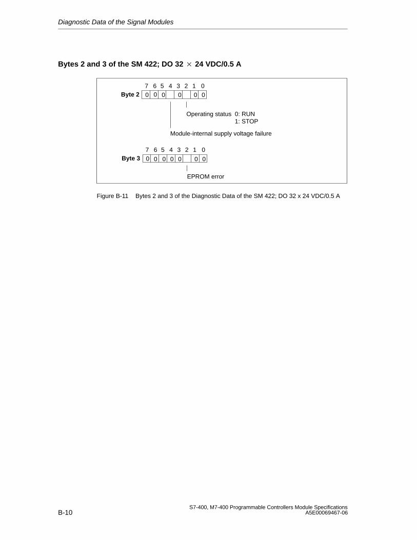
Diagnostic Data of the Signal Modules
B-10S7-400, M7-400 Programmable Controllers Module Specifications
A5E00069467-06
Bytes 2 and 3 of the SM 422; DO 32 24 VDC/0.5 A
Byte 27 6 0
Operating status 0: RUN1: STOP
Module-internal supply voltage failure
5 4 3 2 1
0
Byte 37 6 0
EPROM error
5 4 3 2 1
0
00 0 0 0
0 0 0 0 00
Figure B-11 Bytes 2 and 3 of the Diagnostic Data of the SM 422; DO 32 x 24 VDC/0.5 A
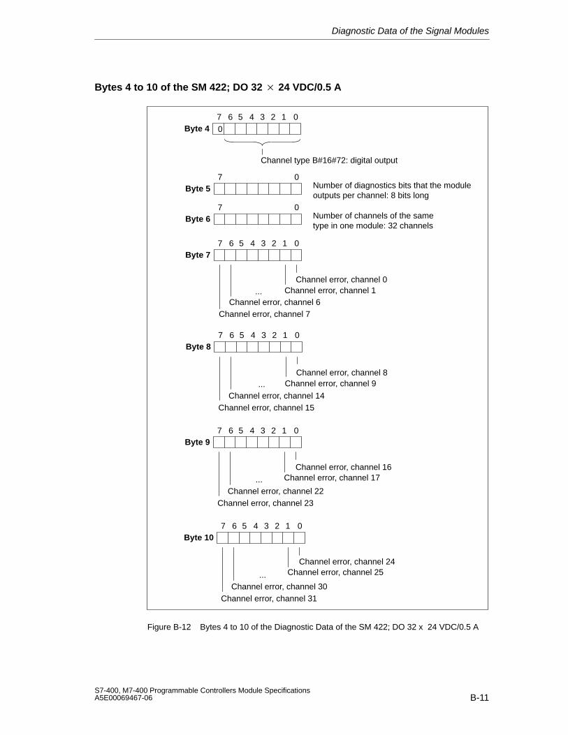
Diagnostic Data of the Signal Modules
B-11S7-400, M7-400 Programmable Controllers Module SpecificationsA5E00069467-06
Bytes 4 to 10 of the SM 422; DO 32 24 VDC/0.5 A
Byte 47 6 05 4 3 2 1
Byte 57 0
Channel type B#16#72: digital output
Number of diagnostics bits that the moduleoutputs per channel: 8 bits long
Byte 67 0
Number of channels of the sametype in one module: 32 channels
Byte 77 6 0
Channel error, channel 0Channel error, channel 1
Channel error, channel 6Channel error, channel 7
5 4 3 2 1
...
0
Byte 87 6 0
Channel error, channel 14Channel error, channel 15
5 4 3 2 1
...Channel error, channel 8
Channel error, channel 9
Byte 97 6 0
Channel error, channel 17
Channel error, channel 22Channel error, channel 23
5 4 3 2 1
...
Channel error, channel 16
Byte 107 6 0
Channel error, channel 30Channel error, channel 31
5 4 3 2 1
... Channel error, channel 25Channel error, channel 24
Figure B-12 Bytes 4 to 10 of the Diagnostic Data of the SM 422; DO 32 x 24 VDC/0.5 A
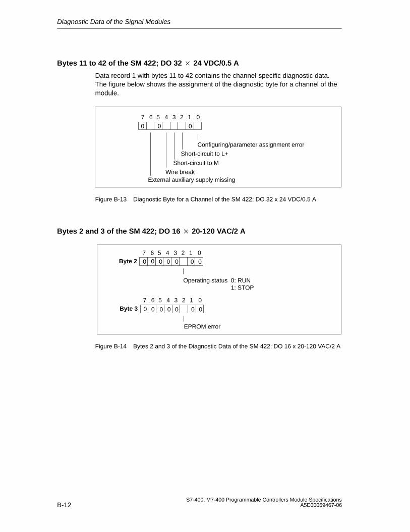
Diagnostic Data of the Signal Modules
B-12S7-400, M7-400 Programmable Controllers Module Specifications
A5E00069467-06
Bytes 11 to 42 of the SM 422; DO 32 24 VDC/0.5 A
Data record 1 with bytes 11 to 42 contains the channel-specific diagnostic data.The figure below shows the assignment of the diagnostic byte for a channel of themodule.
7 6 0
Short-circuit to L+
Short-circuit to M
Wire breakExternal auxiliary supply missing
5 4 3 2 1
0
Configuring/parameter assignment error
0 0
Figure B-13 Diagnostic Byte for a Channel of the SM 422; DO 32 x 24 VDC/0.5 A
Bytes 2 and 3 of the SM 422; DO 16 20-120 VAC/2 A
Byte 27 6 0
Operating status 0: RUN1: STOP
5 4 3 2 1
0
Byte 37 6 0
EPROM error
5 4 3 2 1
0
00 0 0 0
0 0 0 0 00
0
Figure B-14 Bytes 2 and 3 of the Diagnostic Data of the SM 422; DO 16 x 20-120 VAC/2 A
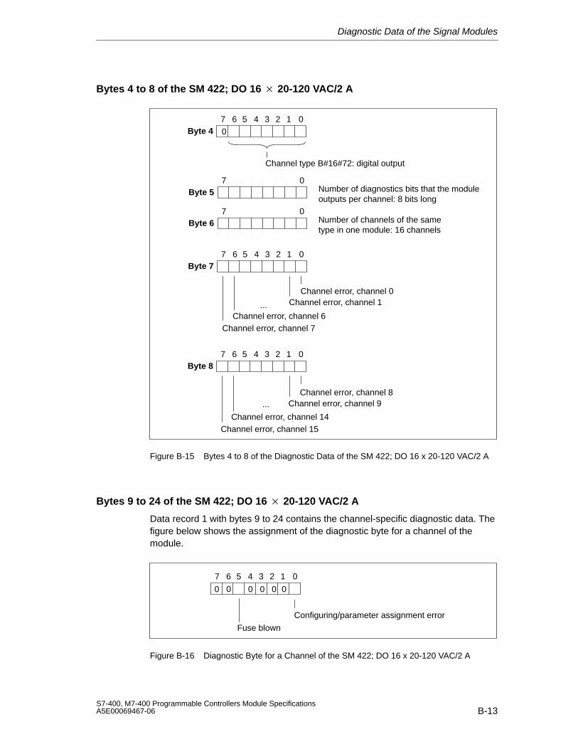
Diagnostic Data of the Signal Modules
B-13S7-400, M7-400 Programmable Controllers Module SpecificationsA5E00069467-06
Bytes 4 to 8 of the SM 422; DO 16 20-120 VAC/2 A
Byte 47 6 05 4 3 2 1
Byte 57 0
Channel type B#16#72: digital output
Number of diagnostics bits that the moduleoutputs per channel: 8 bits long
Byte 67 0
Number of channels of the sametype in one module: 16 channels
0
Byte 77 6 0
Channel error, channel 0Channel error, channel 1
Channel error, channel 6Channel error, channel 7
5 4 3 2 1
...
Byte 87 6 0
Channel error, channel 14Channel error, channel 15
5 4 3 2 1
...Channel error, channel 8
Channel error, channel 9
Figure B-15 Bytes 4 to 8 of the Diagnostic Data of the SM 422; DO 16 x 20-120 VAC/2 A
Bytes 9 to 24 of the SM 422; DO 16 20-120 VAC/2 A
Data record 1 with bytes 9 to 24 contains the channel-specific diagnostic data. Thefigure below shows the assignment of the diagnostic byte for a channel of themodule.
7 6 0
Fuse blown
5 4 3 2 1
0
Configuring/parameter assignment error
0 00 0 0
Figure B-16 Diagnostic Byte for a Channel of the SM 422; DO 16 x 20-120 VAC/2 A
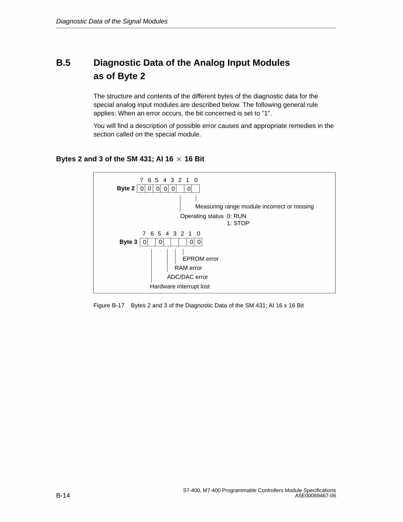
Diagnostic Data of the Signal Modules
B-14S7-400, M7-400 Programmable Controllers Module Specifications
A5E00069467-06
B.5 Diagnostic Data of the Analog Input Modules as of Byte 2
The structure and contents of the different bytes of the diagnostic data for thespecial analog input modules are described below. The following general ruleapplies: When an error occurs, the bit concerned is set to ”1”.
You will find a description of possible error causes and appropriate remedies in thesection called on the special module.
Bytes 2 and 3 of the SM 431; AI 16 16 Bit
Byte 27 6 0
Measuring range module incorrect or missing
Operating status 0: RUN1: STOP
5 4 3 2 1
0
Byte 37 6 0
EPROM error
RAM error
ADC/DAC error
Hardware interrupt lost
5 4 3 2 1
0
0 0 0 0 0
0 0 0
Figure B-17 Bytes 2 and 3 of the Diagnostic Data of the SM 431; AI 16 x 16 Bit
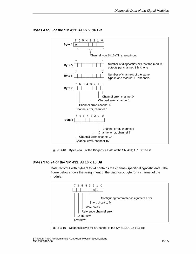
Diagnostic Data of the Signal Modules
B-15S7-400, M7-400 Programmable Controllers Module SpecificationsA5E00069467-06
Bytes 4 to 8 of the SM 431; AI 16 16 Bit
Byte 47 6 05 4 3 2 1
Byte 57 0
Channel type B#16#71: analog input
Number of diagnostics bits that the moduleoutputs per channel: 8 bits long
Byte 67 0
Number of channels of the sametype in one module: 16 channels
Byte 77 6 0
Channel error, channel 0Channel error, channel 1
Channel error, channel 6Channel error, channel 7
5 4 3 2 1
...
0
Byte 87 6 0
Channel error, channel 14Channel error, channel 15
5 4 3 2 1
...Channel error, channel 8
Channel error, channel 9
Figure B-18 Bytes 4 to 8 of the Diagnostic Data of the SM 431; AI 16 x 16 Bit
Bytes 9 to 24 of the SM 431; AI 16 x 16 Bit
Data record 1 with bytes 9 to 24 contains the channel-specific diagnostic data. Thefigure below shows the assignment of the diagnostic byte for a channel of themodule.
7 6 0
Configuring/parameter assignment error
Wire break
UnderflowOverflow
5 4 3 2 1
Short-circuit to M
Reference channel error
00
Figure B-19 Diagnostic Byte for a Channel of the SM 431; AI 16 x 16 Bit
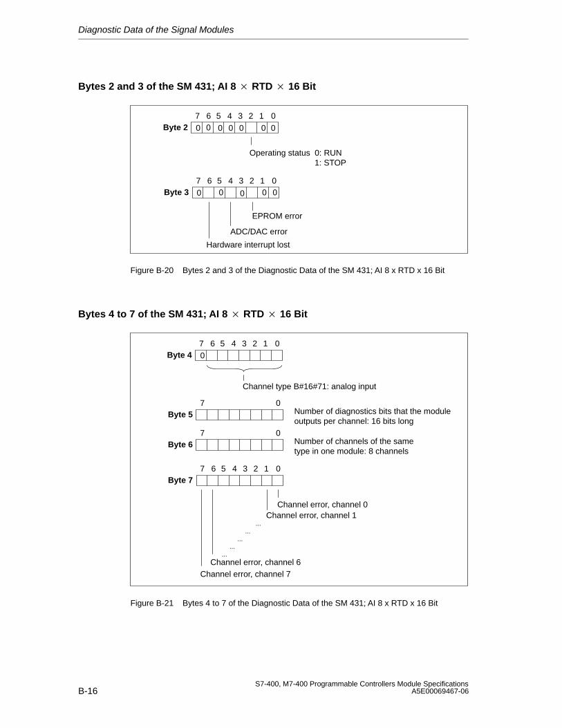
Diagnostic Data of the Signal Modules
B-16S7-400, M7-400 Programmable Controllers Module Specifications
A5E00069467-06
Bytes 2 and 3 of the SM 431; AI 8 RTD 16 Bit
Byte 27 6 0
Operating status 0: RUN1: STOP
5 4 3 2 1
0
Byte 37 6 0
EPROM error
ADC/DAC error
Hardware interrupt lost
5 4 3 2 1
0
0 0 0 0 0
0 0 0
0
0
Figure B-20 Bytes 2 and 3 of the Diagnostic Data of the SM 431; AI 8 x RTD x 16 Bit
Bytes 4 to 7 of the SM 431; AI 8 RTD 16 Bit
Byte 47 6 05 4 3 2 1
Byte 57 0
Channel type B#16#71: analog input
Number of diagnostics bits that the moduleoutputs per channel: 16 bits long
Byte 67 0
Number of channels of the sametype in one module: 8 channels
Byte 77 6 0
Channel error, channel 0Channel error, channel 1
Channel error, channel 6Channel error, channel 7
5 4 3 2 1
......
......
...
0
Figure B-21 Bytes 4 to 7 of the Diagnostic Data of the SM 431; AI 8 x RTD x 16 Bit
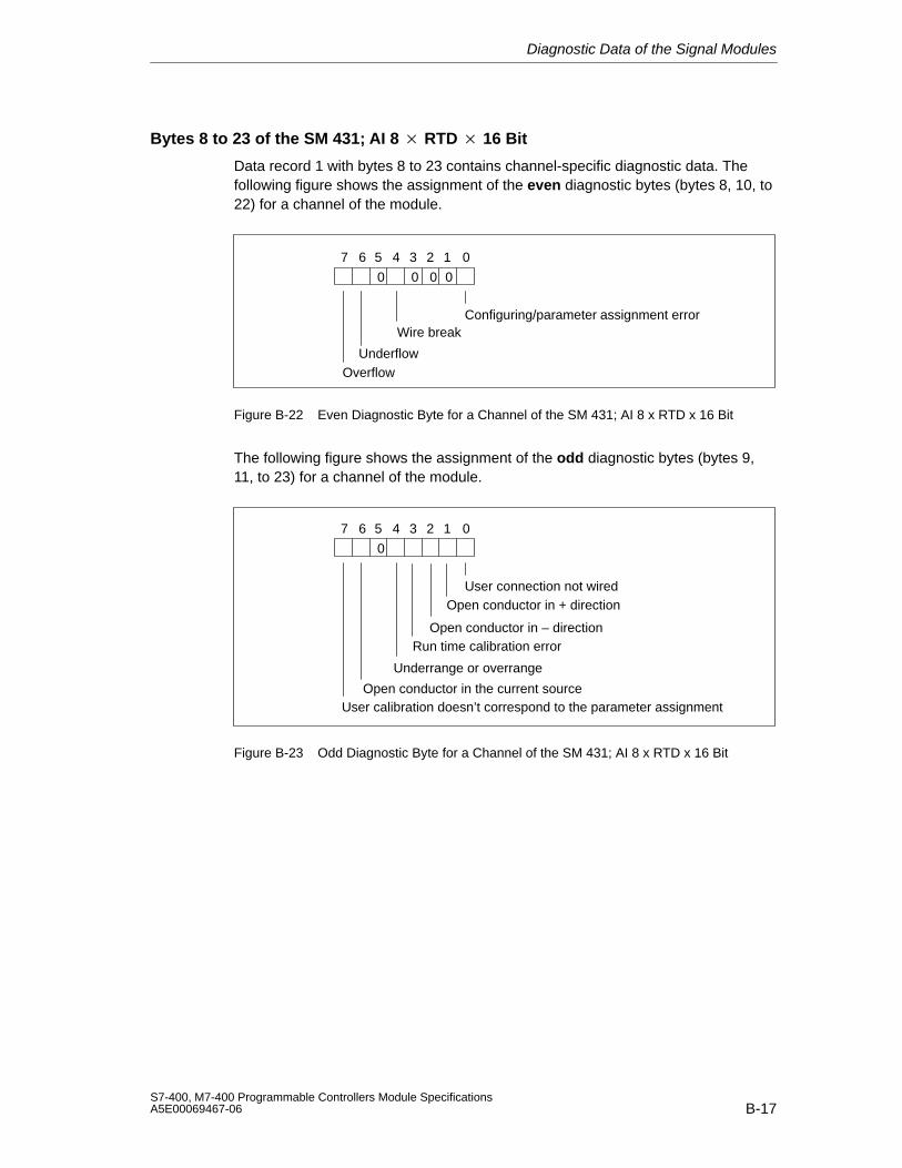
Diagnostic Data of the Signal Modules
B-17S7-400, M7-400 Programmable Controllers Module SpecificationsA5E00069467-06
Bytes 8 to 23 of the SM 431; AI 8 RTD 16 Bit
Data record 1 with bytes 8 to 23 contains channel-specific diagnostic data. Thefollowing figure shows the assignment of the even diagnostic bytes (bytes 8, 10, to22) for a channel of the module.
7 6 0
Configuring/parameter assignment errorWire break
UnderflowOverflow
5 4 3 2 1
0000
Figure B-22 Even Diagnostic Byte for a Channel of the SM 431; AI 8 x RTD x 16 Bit
The following figure shows the assignment of the odd diagnostic bytes (bytes 9,11, to 23) for a channel of the module.
7 6 0
User connection not wired
Run time calibration error
Underrange or overrange
5 4 3 2 1
0
Open conductor in + direction
Open conductor in – direction
Open conductor in the current sourceUser calibration doesn’t correspond to the parameter assignment
Figure B-23 Odd Diagnostic Byte for a Channel of the SM 431; AI 8 x RTD x 16 Bit
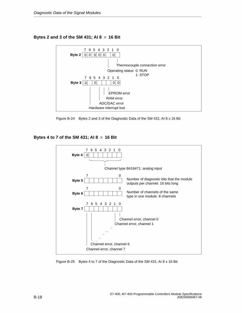
Diagnostic Data of the Signal Modules
B-18S7-400, M7-400 Programmable Controllers Module Specifications
A5E00069467-06
Bytes 2 and 3 of the SM 431; AI 8 16 Bit
Byte 27 6 0
Operating status 0: RUN1: STOP
5 4 3 2 1
0
Byte 37 6 0
EPROM error
ADC/DAC errorHardware interrupt lost
5 4 3 2 1
0
0 0 0 0 0
0 0 0
Thermocouple connection error
RAM error
Figure B-24 Bytes 2 and 3 of the Diagnostic Data of the SM 431; AI 8 x 16 Bit
Bytes 4 to 7 of the SM 431; AI 8 16 Bit
Byte 47 6 05 4 3 2 1
Byte 57 0
Channel type B#16#71: analog input
Number of diagnostic bits that the moduleoutputs per channel: 16 bits long
Byte 67 0
Number of channels of the sametype in one module: 8 channels
Byte 77 6 0
Channel error, channel 0Channel error, channel 1
Channel error, channel 6Channel error, channel 7
5 4 3 2 1
......
......
...
0
Figure B-25 Bytes 4 to 7 of the Diagnostic Data of the SM 431; AI 8 x 16 Bit
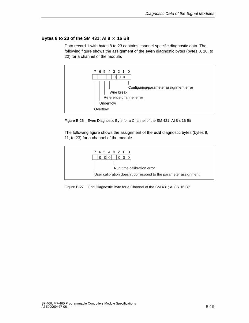
Diagnostic Data of the Signal Modules
B-19S7-400, M7-400 Programmable Controllers Module SpecificationsA5E00069467-06
Bytes 8 to 23 of the SM 431; AI 8 16 Bit
Data record 1 with bytes 8 to 23 contains channel-specific diagnostic data. Thefollowing figure shows the assignment of the even diagnostic bytes (bytes 8, 10, to22) for a channel of the module.
7 6 0
Configuring/parameter assignment errorWire break
Underflow
Overflow
5 4 3 2 1
000
Reference channel error
Figure B-26 Even Diagnostic Byte for a Channel of the SM 431; AI 8 x 16 Bit
The following figure shows the assignment of the odd diagnostic bytes (bytes 9,11, to 23) for a channel of the module.
7 6 0
Run time calibration error
5 4 3 2 1
0
User calibration doesn’t correspond to the parameter assignment
0 0 0 0 0
Figure B-27 Odd Diagnostic Byte for a Channel of the SM 431; AI 8 x 16 Bit

Diagnostic Data of the Signal Modules
B-20S7-400, M7-400 Programmable Controllers Module Specifications
A5E00069467-06
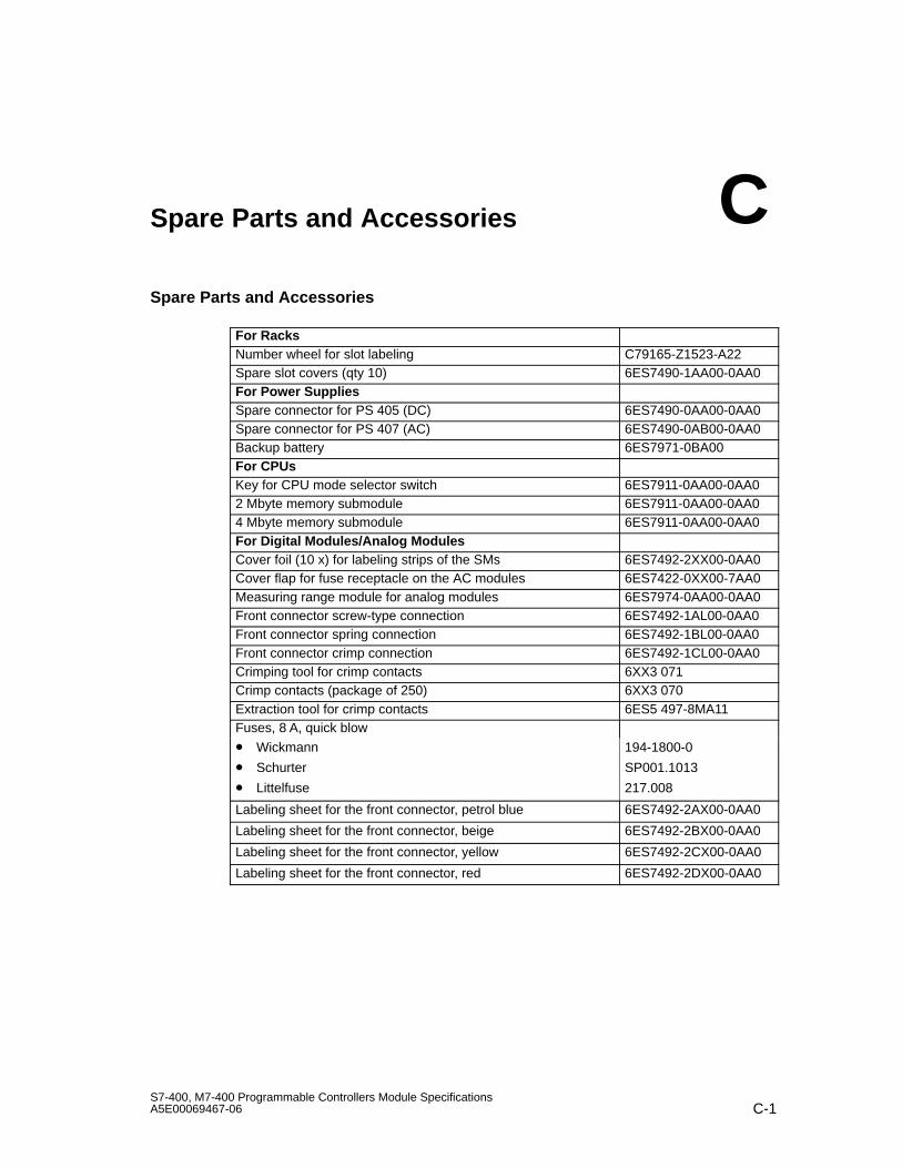
C-1S7-400, M7-400 Programmable Controllers Module SpecificationsA5E00069467-06
Spare Parts and Accessories
Spare Parts and Accessories
For RacksNumber wheel for slot labeling C79165-Z1523-A22Spare slot covers (qty 10) 6ES7490-1AA00-0AA0For Power SuppliesSpare connector for PS 405 (DC) 6ES7490-0AA00-0AA0Spare connector for PS 407 (AC) 6ES7490-0AB00-0AA0Backup battery 6ES7971-0BA00For CPUsKey for CPU mode selector switch 6ES7911-0AA00-0AA02 Mbyte memory submodule 6ES7911-0AA00-0AA04 Mbyte memory submodule 6ES7911-0AA00-0AA0For Digital Modules/Analog ModulesCover foil (10 x) for labeling strips of the SMs 6ES7492-2XX00-0AA0Cover flap for fuse receptacle on the AC modules 6ES7422-0XX00-7AA0Measuring range module for analog modules 6ES7974-0AA00-0AA0Front connector screw-type connection 6ES7492-1AL00-0AA0Front connector spring connection 6ES7492-1BL00-0AA0Front connector crimp connection 6ES7492-1CL00-0AA0Crimping tool for crimp contacts 6XX3 071Crimp contacts (package of 250) 6XX3 070Extraction tool for crimp contacts 6ES5 497-8MA11Fuses, 8 A, quick blow
• Wickmann
• Schurter
• Littelfuse
194-1800-0
SP001.1013
217.008
Labeling sheet for the front connector, petrol blue 6ES7492-2AX00-0AA0
Labeling sheet for the front connector, beige 6ES7492-2BX00-0AA0
Labeling sheet for the front connector, yellow 6ES7492-2CX00-0AA0
Labeling sheet for the front connector, red 6ES7492-2DX00-0AA0
C
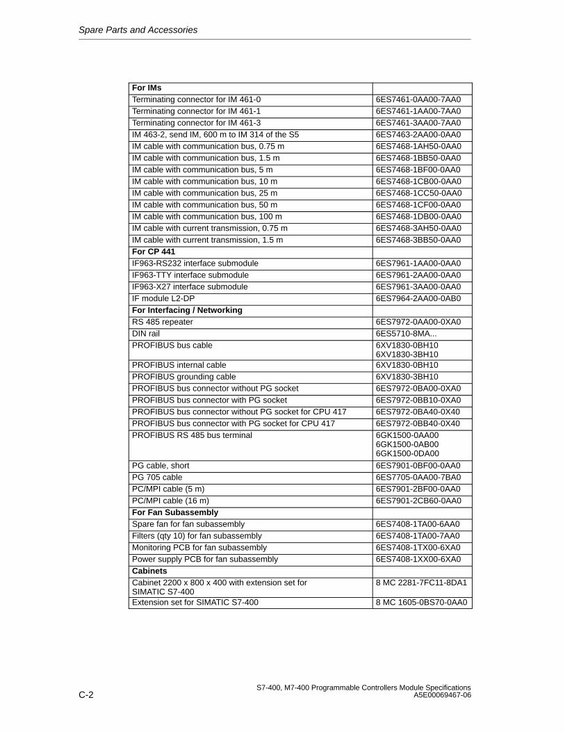
Spare Parts and Accessories
C-2S7-400, M7-400 Programmable Controllers Module Specifications
A5E00069467-06
For IMsTerminating connector for IM 461-0 6ES7461-0AA00-7AA0Terminating connector for IM 461-1 6ES7461-1AA00-7AA0Terminating connector for IM 461-3 6ES7461-3AA00-7AA0IM 463-2, send IM, 600 m to IM 314 of the S5 6ES7463-2AA00-0AA0IM cable with communication bus, 0.75 m 6ES7468-1AH50-0AA0IM cable with communication bus, 1.5 m 6ES7468-1BB50-0AA0IM cable with communication bus, 5 m 6ES7468-1BF00-0AA0IM cable with communication bus, 10 m 6ES7468-1CB00-0AA0IM cable with communication bus, 25 m 6ES7468-1CC50-0AA0IM cable with communication bus, 50 m 6ES7468-1CF00-0AA0IM cable with communication bus, 100 m 6ES7468-1DB00-0AA0IM cable with current transmission, 0.75 m 6ES7468-3AH50-0AA0IM cable with current transmission, 1.5 m 6ES7468-3BB50-0AA0For CP 441IF963-RS232 interface submodule 6ES7961-1AA00-0AA0IF963-TTY interface submodule 6ES7961-2AA00-0AA0IF963-X27 interface submodule 6ES7961-3AA00-0AA0IF module L2-DP 6ES7964-2AA00-0AB0For Interfacing / NetworkingRS 485 repeater 6ES7972-0AA00-0XA0DIN rail 6ES5710-8MA...PROFIBUS bus cable 6XV1830-0BH10
6XV1830-3BH10PROFIBUS internal cable 6XV1830-0BH10PROFIBUS grounding cable 6XV1830-3BH10PROFIBUS bus connector without PG socket 6ES7972-0BA00-0XA0PROFIBUS bus connector with PG socket 6ES7972-0BB10-0XA0PROFIBUS bus connector without PG socket for CPU 417 6ES7972-0BA40-0X40PROFIBUS bus connector with PG socket for CPU 417 6ES7972-0BB40-0X40PROFIBUS RS 485 bus terminal 6GK1500-0AA00
6GK1500-0AB006GK1500-0DA00
PG cable, short 6ES7901-0BF00-0AA0PG 705 cable 6ES7705-0AA00-7BA0PC/MPI cable (5 m) 6ES7901-2BF00-0AA0PC/MPI cable (16 m) 6ES7901-2CB60-0AA0For Fan SubassemblySpare fan for fan subassembly 6ES7408-1TA00-6AA0Filters (qty 10) for fan subassembly 6ES7408-1TA00-7AA0Monitoring PCB for fan subassembly 6ES7408-1TX00-6XA0Power supply PCB for fan subassembly 6ES7408-1XX00-6XA0CabinetsCabinet 2200 x 800 x 400 with extension set forSIMATIC S7-400
8 MC 2281-7FC11-8DA1
Extension set for SIMATIC S7-400 8 MC 1605-0BS70-0AA0
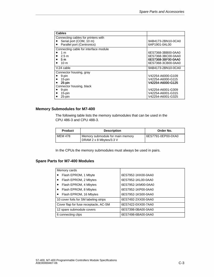
Spare Parts and Accessories
C-3S7-400, M7-400 Programmable Controllers Module SpecificationsA5E00069467-06
CablesConnecting cables for printers with• Serial port (COM, 10 m)• Parallel port (Centronics)
9AB4173-2BN10-0CA06AP1901-0AL00
Connecting cable for interface module•• 1 m•
6ES7368-3BB00-0AA0• 2.5 m• 5 m
6ES7368-3BC00-0AA06ES7368-3BF00-0AA0• 5 m
• 10 m6ES7368-3BF00-0AA06ES7368-3CB00-0AA0
V.24 cable 9AB4173-2BN10-0CA0Connector housing, gray• 9-pin• 15-pin• 25-pin
V42254-A6000-G109V42254-A6000-G115V42254-A6000-G12525-pin
Connector housing, black• 9-pin• 15-pin• 25-pin
V42254-A6000-G125
V42254-A6001-G309V42254-A6001-G315V42254-A6001-G325
Memory Submodules for M7-400
The following table lists the memory submodules that can be used in theCPU 486-3 and CPU 488-3.
Product Description Order No.
MEM 478 Memory submodule for main memoryDRAM 2 x 8 Mbytes/3.3 V
6ES7791-0EP00-0XA0
In the CPUs the memory submodules must always be used in pairs.
Spare Parts for M7-400 Modules
Memory cards
• Flash EPROM, 1 Mbyte
• Flash EPROM, 2 Mbytes
• Flash EPROM, 4 Mbytes
• Flash EPROM, 8 Mbytes
• Flash EPROM, 16 Mbytes
6ES7952-1KK00-0AA0
6ES7952-1KL00-0AA0
6ES7952-1KM00-0AA0
6ES7952-1KP00-0AA0
6ES7952-1KS00-0AA0
10 cover foils for SM labeling strips 6ES7492-2XX00-0AA0
Cover flap for fuse receptacle, AC-SM 6ES7422-0XX00-7AA0
12 spare submodule covers 6ES7398-0BA00-0AA0
6 connecting clips 6ES7498-6BA00-0AA0

Spare Parts and Accessories
C-4S7-400, M7-400 Programmable Controllers Module Specifications
A5E00069467-06
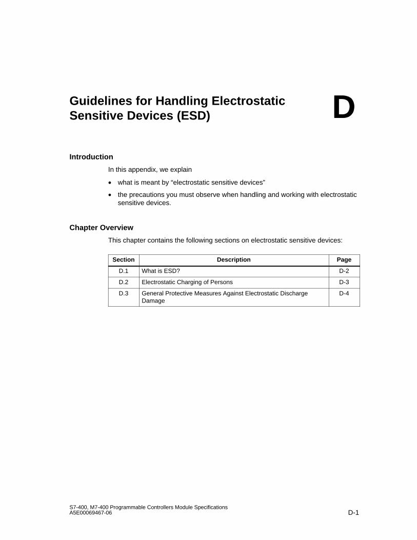
D-1S7-400, M7-400 Programmable Controllers Module SpecificationsA5E00069467-06
Guidelines for Handling ElectrostaticSensitive Devices (ESD)
Introduction
In this appendix, we explain
• what is meant by “electrostatic sensitive devices”
• the precautions you must observe when handling and working with electrostaticsensitive devices.
Chapter Overview
This chapter contains the following sections on electrostatic sensitive devices:
Section Description Page
D.1 What is ESD? D-2
D.2 Electrostatic Charging of Persons D-3
D.3 General Protective Measures Against Electrostatic DischargeDamage
D-4
D
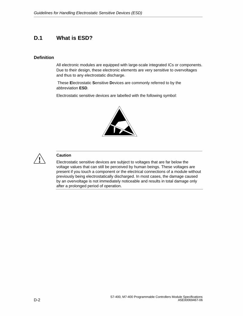
Guidelines for Handling Electrostatic Sensitive Devices (ESD)
D-2S7-400, M7-400 Programmable Controllers Module Specifications
A5E00069467-06
D.1 What is ESD?
Definition
All electronic modules are equipped with large-scale integrated ICs or components.Due to their design, these electronic elements are very sensitive to overvoltagesand thus to any electrostatic discharge.
These Electrostatic Sensitive Devices are commonly referred to by theabbreviation ESD.
Electrostatic sensitive devices are labelled with the following symbol:
!Caution
Electrostatic sensitive devices are subject to voltages that are far below thevoltage values that can still be perceived by human beings. These voltages arepresent if you touch a component or the electrical connections of a module withoutpreviously being electrostatically discharged. In most cases, the damage causedby an overvoltage is not immediately noticeable and results in total damage onlyafter a prolonged period of operation.
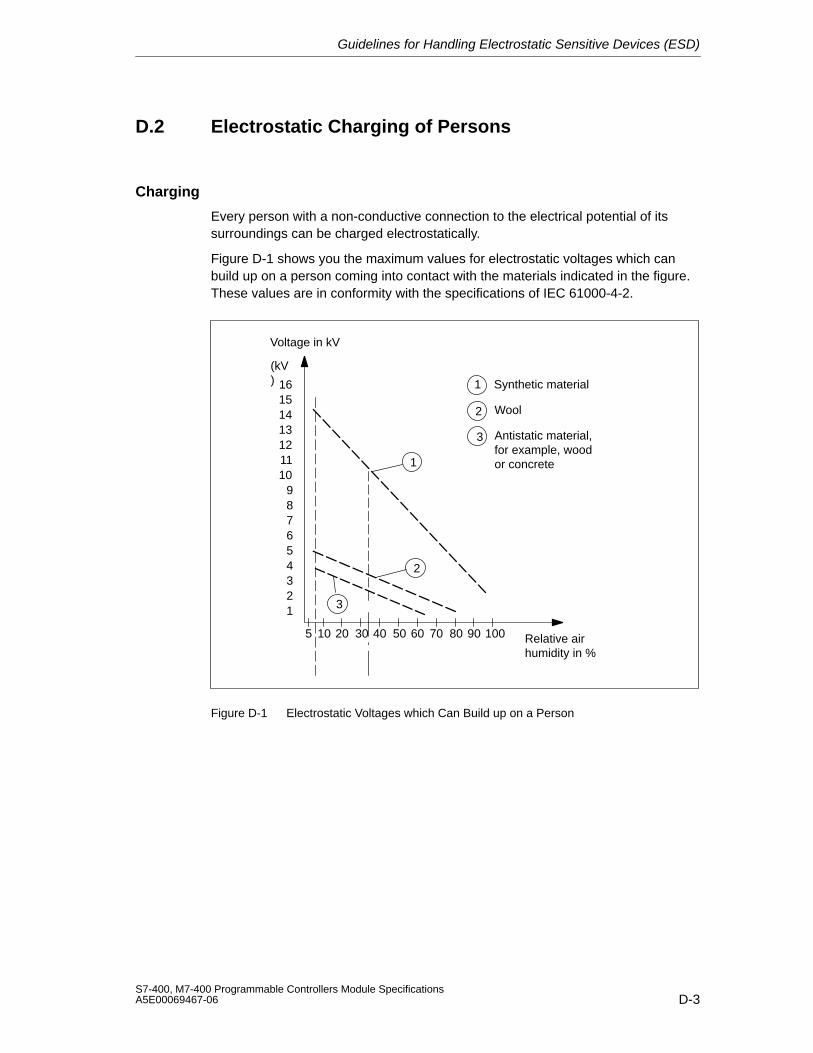
Guidelines for Handling Electrostatic Sensitive Devices (ESD)
D-3S7-400, M7-400 Programmable Controllers Module SpecificationsA5E00069467-06
D.2 Electrostatic Charging of Persons
Charging
Every person with a non-conductive connection to the electrical potential of itssurroundings can be charged electrostatically.
Figure D-1 shows you the maximum values for electrostatic voltages which canbuild up on a person coming into contact with the materials indicated in the figure.These values are in conformity with the specifications of IEC 61000-4-2.
Voltage in kV
123456789
10111213141516
(kV)
5 10 20 30 40 50 60 70 80 90 100 Relative airhumidity in %
1
3
1 Synthetic material
2 Wool
3 Antistatic material, for example, wood or concrete
2
Figure D-1 Electrostatic Voltages which Can Build up on a Person
Guidelines for Handling Electrostatic Sensitive Devices (ESD)
D-4S7-400, M7-400 Programmable Controllers Module Specifications
A5E00069467-06
D.3 General Protective Measures Against ElectrostaticDischarge Damage
Ensure Sufficient Grounding
Make sure that the personnel, working surfaces and packaging are sufficientlygrounded when handling electrostatic sensitive devices. You thus avoidelectrostatic charging.
Avoid Direct Contact
You should touch electrostatic sensitive devices only if it is unavoidable(for example, during maintenance work). Hold modules without touching the pins ofcomponents or printed conductors. In this way, the discharged energy cannot affectthe sensitive devices.
If you have to carry out measurements on a module, you must discharge your bodybefore you start the measurement by touching grounded metallic parts. Usegrounded measuring devices only.
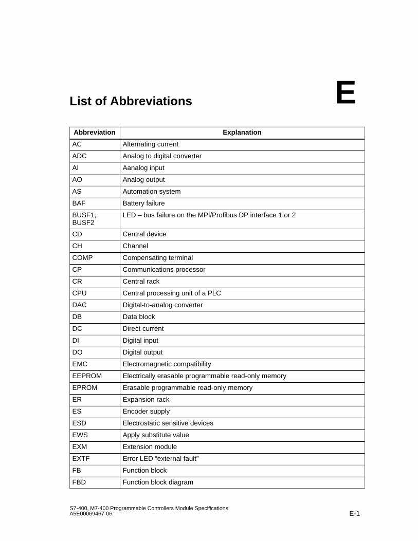
E-1S7-400, M7-400 Programmable Controllers Module SpecificationsA5E00069467-06
List of Abbreviations
Abbreviation Explanation
AC Alternating current
ADC Analog to digital converter
AI Aanalog input
AO Analog output
AS Automation system
BAF Battery failure
BUSF1;BUSF2
LED – bus failure on the MPI/Profibus DP interface 1 or 2
CD Central device
CH Channel
COMP Compensating terminal
CP Communications processor
CR Central rack
CPU Central processing unit of a PLC
DAC Digital-to-analog converter
DB Data block
DC Direct current
DI Digital input
DO Digital output
EMC Electromagnetic compatibility
EEPROM Electrically erasable programmable read-only memory
EPROM Erasable programmable read-only memory
ER Expansion rack
ES Encoder supply
ESD Electrostatic sensitive devices
EWS Apply substitute value
EXM Extension module
EXTF Error LED “external fault”
FB Function block
FBD Function block diagram
E
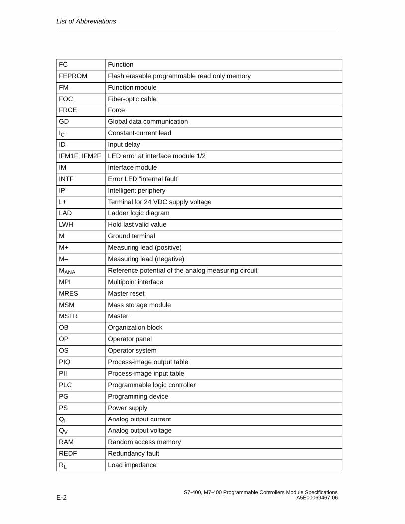
List of Abbreviations
E-2S7-400, M7-400 Programmable Controllers Module Specifications
A5E00069467-06
FC Function
FEPROM Flash erasable programmable read only memory
FM Function module
FOC Fiber-optic cable
FRCE Force
GD Global data communication
IC Constant-current lead
ID Input delay
IFM1F; IFM2F LED error at interface module 1/2
IM Interface module
INTF Error LED “internal fault”
IP Intelligent periphery
L+ Terminal for 24 VDC supply voltage
LAD Ladder logic diagram
LWH Hold last valid value
M Ground terminal
M+ Measuring lead (positive)
M– Measuring lead (negative)
MANA Reference potential of the analog measuring circuit
MPI Multipoint interface
MRES Master reset
MSM Mass storage module
MSTR Master
OB Organization block
OP Operator panel
OS Operator system
PIQ Process-image output table
PII Process-image input table
PLC Programmable logic controller
PG Programming device
PS Power supply
QI Analog output current
QV Analog output voltage
RAM Random access memory
REDF Redundancy fault
RL Load impedance
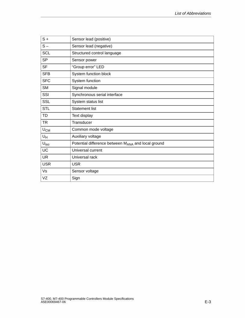
List of Abbreviations
E-3S7-400, M7-400 Programmable Controllers Module SpecificationsA5E00069467-06
S + Sensor lead (positive)
S – Sensor lead (negative)
SCL Structured control language
SP Sensor power
SF “Group error” LED
SFB System function block
SFC System function
SM Signal module
SSI Synchronous serial interface
SSL System status list
STL Statement list
TD Text display
TR Transducer
UCM Common mode voltage
UH Auxiliary voltage
Uiso Potential difference between MANA and local ground
UC Universal current
UR Universal rack
USR USR
Vs Sensor voltage
VZ Sign

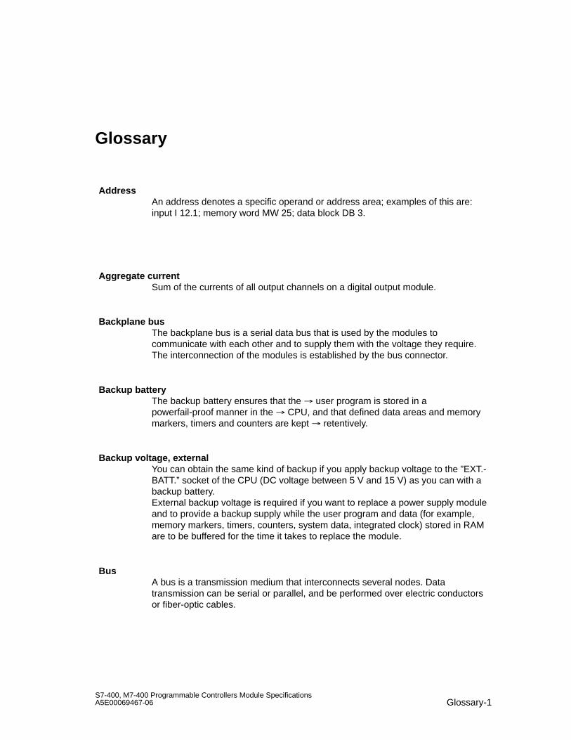
Glossary-1S7-400, M7-400 Programmable Controllers Module SpecificationsA5E00069467-06
Glossary
AddressAn address denotes a specific operand or address area; examples of this are:input I 12.1; memory word MW 25; data block DB 3.
Aggregate currentSum of the currents of all output channels on a digital output module.
Backplane busThe backplane bus is a serial data bus that is used by the modules tocommunicate with each other and to supply them with the voltage they require.The interconnection of the modules is established by the bus connector.
Backup batteryThe backup battery ensures that the user program is stored in apowerfail-proof manner in the CPU, and that defined data areas and memorymarkers, timers and counters are kept retentively.
Backup voltage, externalYou can obtain the same kind of backup if you apply backup voltage to the ”EXT.-BATT.” socket of the CPU (DC voltage between 5 V and 15 V) as you can with abackup battery.External backup voltage is required if you want to replace a power supply moduleand to provide a backup supply while the user program and data (for example,memory markers, timers, counters, system data, integrated clock) stored in RAMare to be buffered for the time it takes to replace the module.
BusA bus is a transmission medium that interconnects several nodes. Datatransmission can be serial or parallel, and be performed over electric conductorsor fiber-optic cables.

Glossary
Glossary-2S7-400, M7-400 Programmable Controllers Module Specifications
A5E00069467-06
Bus connectorA physical connection between the bus nodes and the bus cable.
Bus segmentA bus segment is a self-contained section of a serial bus system. Bus segmentsare interconnected by means of repeaters.
Central controllerAn S7-400 consists of a central controller (CC) that can be allocated expansionunits (EU), as required. The central controller is the mounting rack that containsthe CPU.
Central processing unitCPU
Cold restart Restart of the programmable controller and its user program, after all thedynamic data (variables of the input/output image, internal registers, timers,counters, etc. and the corresponding program sections) have been reset to aspecified value.A cold restart can be automatically triggered, such as after a power failure or lossof information in dynamic memory sections, etc., or manually by pressing thereset key.
Common mode voltageA voltage that is common to all inputs/outputs of a group and is measuredbetween this group and any reference point (usually to ground).
Communication loadThis is the load on the cyclic program scanning of a CPU caused bycommunication operations (for example, via PROFIBUS DP).To prevent communication operations overloading cyclic program scanning, youcan set the maximum permissible load that communication can place on the scancycle by parameter assignment in STEP 7.
Communication processorProgrammable module for communication tasks, such as networking,point-to-point connection.
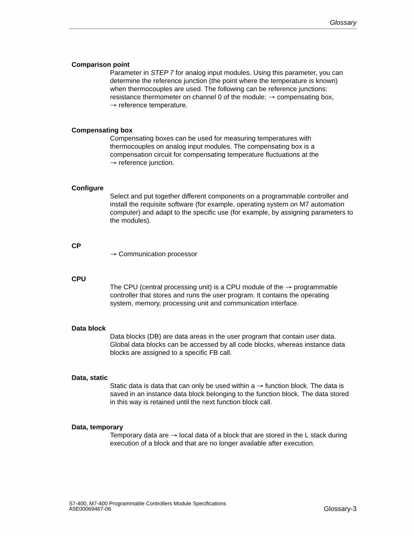
Glossary
Glossary-3S7-400, M7-400 Programmable Controllers Module SpecificationsA5E00069467-06
Comparison point Parameter in STEP 7 for analog input modules. Using this parameter, you candetermine the reference junction (the point where the temperature is known)when thermocouples are used. The following can be reference junctions:resistance thermometer on channel 0 of the module; compensating box,reference temperature.
Compensating boxCompensating boxes can be used for measuring temperatures withthermocouples on analog input modules. The compensating box is acompensation circuit for compensating temperature fluctuations at thereference junction.
ConfigureSelect and put together different components on a programmable controller andinstall the requisite software (for example, operating system on M7 automationcomputer) and adapt to the specific use (for example, by assigning parameters tothe modules).
CP Communication processor
CPUThe CPU (central processing unit) is a CPU module of the programmablecontroller that stores and runs the user program. It contains the operatingsystem, memory, processing unit and communication interface.
Data blockData blocks (DB) are data areas in the user program that contain user data.Global data blocks can be accessed by all code blocks, whereas instance datablocks are assigned to a specific FB call.
Data, staticStatic data is data that can only be used within a function block. The data issaved in an instance data block belonging to the function block. The data storedin this way is retained until the next function block call.
Data, temporaryTemporary data are local data of a block that are stored in the L stack duringexecution of a block and that are no longer available after execution.
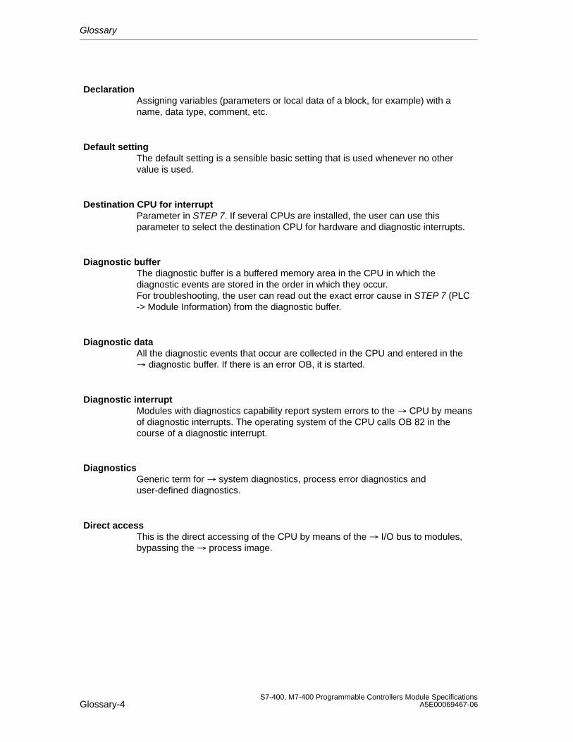
Glossary
Glossary-4S7-400, M7-400 Programmable Controllers Module Specifications
A5E00069467-06
DeclarationAssigning variables (parameters or local data of a block, for example) with aname, data type, comment, etc.
Default settingThe default setting is a sensible basic setting that is used whenever no othervalue is used.
Destination CPU for interruptParameter in STEP 7. If several CPUs are installed, the user can use thisparameter to select the destination CPU for hardware and diagnostic interrupts.
Diagnostic bufferThe diagnostic buffer is a buffered memory area in the CPU in which thediagnostic events are stored in the order in which they occur.For troubleshooting, the user can read out the exact error cause in STEP 7 (PLC-> Module Information) from the diagnostic buffer.
Diagnostic dataAll the diagnostic events that occur are collected in the CPU and entered in the diagnostic buffer. If there is an error OB, it is started.
Diagnostic interruptModules with diagnostics capability report system errors to the CPU by meansof diagnostic interrupts. The operating system of the CPU calls OB 82 in thecourse of a diagnostic interrupt.
DiagnosticsGeneric term for system diagnostics, process error diagnostics anduser-defined diagnostics.
Direct accessThis is the direct accessing of the CPU by means of the I/O bus to modules,bypassing the process image.
Glossary
Glossary-5S7-400, M7-400 Programmable Controllers Module SpecificationsA5E00069467-06
Direct communicationDirect communication involves assigning local input address areas of anintelligent DP slave (for example, CPU 315-2 with PROFIBUS DP connection) orof a DP master to the input address areas of a PROFIBUS DP partner. Theintelligent DP slave or DP master receives the input data that the PROFIBUS DPpartner sends to its DP master via these assigned input address areas.
DP masterA node with a master function in the PROFIBUS DP. A master that behaves inaccordance with the EN 50170 with the DP protocol is a DP master. The busaccess right (token) is only passed amongst masters. The slaves, in this case DPslaves, can only respond on the request of a master. The following distinctionsare made:DP master (class 1): executes the user data communication with the DP slavesassigned to it.DP master (class 2): provides services such as: reading of the input/output data,diagnostics, global control.
DP slaveA slave that is operated on the PROFIBUS bus system with thePROFIBUS DP protocol is called a DP slave.
Edge, fallingSignal status change from 1 to 0
Edge, risingSignal status change from 0 to 1
EEPROMElectrically erasable programmable read-only memory
EPROMErasable programmable read-only memory
EquidistanceEquidistance is a DP bus cycle that is accurate to a few s and can be configuredin STEP 7.
Glossary
Glossary-6S7-400, M7-400 Programmable Controllers Module Specifications
A5E00069467-06
Equipotential bondingAn electrical connection (equipotential bonding conductor) that brings the bodiesof electrical resources and foreign conductive bodies to an identical orapproximately identical potential in order to avoid interfering or hazardousvoltages between these bodies.
External load memory Memory card
FB Function block
FC Function
FEPROMIn their ability to retain data in the event of a power failure (even without a backupbattery), FEPROMs (flash erasable programmable read only memories) are theequivalent of the electrically erasable EEPROMS, but can be erasedconsiderably more quickly.
Fiber-optic cableA fiber-optic cable is a transmission medium made of glass fiber or plastic.Fiber-optic cables are resistant to electromagnetic faults and they make fast datatransfer rates possible.
ForceThe “Force” function overwrites a variable (for example, memory marker, output)with a value defined by the user.At the same time, the variable is assigned write protection so that this valuecannot be modified from any point (including from the STEP 7user program). Thevalue is retained after the programming device is disconnected.Write protection is not canceled until the ”Unforce” function is called and thevariable is written again with the value defined by the user program.During commissioning, for example, the “Force” function allows certain outputs tobe set to the ”ON” state for any length of time even if the logic operations of theuser program are not fulfilled (for example, because inputs are not wired).
FREEZEControl command. The inputs of the DP slaves are frozen to the current value.
Glossary
Glossary-7S7-400, M7-400 Programmable Controllers Module SpecificationsA5E00069467-06
FunctionA function (FC) in accordance with IEC 1131-3 is a code block without static data. A function allows parameters to be passed in the user program.Functions are therefore suitable for programming complex functions, such ascalculations that are frequently repeated.
Functional groundingGrounding which has the sole purpose of safeguarding the intended function ofthe electrical equipment. Functional grounding short-circuits interference voltagethat would otherwise have an impermissible impact on the equipment.
Function blockA function block (FB) in accordance with IEC 1131-3 is a code block with static data. Because an FB has a memory, its parameters (outputs, forexample) can be accessed from any position in the user program.
Fuse blownParameter in STEP 7 for digital output modules. When the parameter is enabled,the failure of one or more fuses is detected by the module. With correspondingparameter assignment, a diagnostic interrupt is triggered.
Global dataGlobal data are data that can be addressed from any code block (FC, FB,OB). In detail, this refers to bit memories (M), inputs (I), outputs (Q), timers,counters and data blocks (DB). Absolute or symbolic access is possible to globaldata.
Global data communicationGlobal data communication is a method of transferring global data betweenCPUs.
GroundThe ground is the total number of all the interconnected inactive parts of a devicethat cannot take on a hazardous voltage in the event of a fault.
GroundThe conductive ground whose electric potential can be set to zero at any point.In the proximity of grounding electrodes, the ground can have a potential otherthan zero. The term ”reference ground” is frequently used to describe suchcircumstances.
Glossary
Glossary-8S7-400, M7-400 Programmable Controllers Module Specifications
A5E00069467-06
Ground, toTo ground means to connect an electrically conductive part via a groundingsystem to the grounding electrode (one or more conductive parts having a verygood contact to ground).
Hardware interruptA hardware interrupt is triggered by interrupt-triggering modules in response to aparticular event in the process (limit value violation; the module has completedthe cyclic change of its channels).The hardware interrupt is reported to the CPU. In accordance with the priority ofthis interrupt, the organization block assigned to it is processed.
Input delayParameter in STEP 7 for digital input modules. The input delay is used tosuppress injected interference. Interfering pulses from 0 ms to the set input delayare suppressed.The set input delay is subject to a tolerance that can be obtained from thetechnical specifications of the module. A high input delay suppresses longinterfering pulses, whereas a low input delay suppresses short ones.The permissible input delay depends on the length of the cable between theencoder and the module. For example, a high input delay has to be set for longunshielded supply conductors to the encoder (longer than 100m).
Integration timeThe integration time is the inverse value of the interference frequencysuppression in ms.
Interface, multipointMPI
Interference frequency suppressionParameter in STEP 7 for analog input modules. The frequency of the AC networkcan interfere with the measured value, especially with measurements in lowvoltage ranges and with thermocouples. This parameter is used by the user tospecify the prevailing line frequency on his system.
InterruptThe SIMATIC S7 is familiar with 28 different run-time level, which govern runningof the user program. These run-time levels include interrupts such as hardwareinterrupts, among other things. When an interrupt occurs, the operating systemautomatically calls an assigned organization block in which the user can programthe reaction he wants (for example, in an FB).
Glossary
Glossary-9S7-400, M7-400 Programmable Controllers Module SpecificationsA5E00069467-06
Interrupt, diagnostic Diagnostic Interrupt
Interrupt, end-of-scan-cycle Hardwareinterrupt
Interrupt, hardware Hardware interrupt
Interrupt response timeThe interrupt response time is the time from when an interrupt signal first occursto calling the first instruction in the interrupt OB. The following general ruleapplies: Higher priority interrupts take precedence. This means that the interruptresponse time is increased by the program processing time of the higher priorityinterrupt OBs and interrupt OBs with the same priority that have not yet beenprocessed (queue).
I/O busThis is part of the backplane bus in the programmable controller, optimized forthe rapid exchange of signals between the CPU(s) and the signal modules.User data (for example, digital input signals of a signal module) and system data(for example, default parameter data records of a signal module) are transferredvia the I/O bus.
IsolatedWith optically isolated input/output modules, the reference potentials of thecontrol and load circuit are galvanically isolated (by an optocoupler, contactassembly or repeater, for example). Input/output circuits can be connected tocommon potential.
Keep last value (KLV)The module retains the last value read out before STOP mode.
Load memoryThe load memory is part of a programmable module (CPU, CP). It containsobjects generated by the programming device (load objects). It is implementedeither as a plug-in memory card or a permanently integrated memory. In the caseof SIMATIC M7, the load memory can also be defined as a directory on the harddisk.
Glossary
Glossary-10S7-400, M7-400 Programmable Controllers Module Specifications
A5E00069467-06
Local dataLocal data are data assigned to a code block that is declared in its declaration section and its variable declaration. It includes (depending on theblock): formal parameters, static data, temporary data.
Logic blockIn the context of SIMATIC S7, a logic block is a block that contains part of theSTEP 7 user program. By contrast, a data block only contains data. There arethe following logic blocks: organization blocks (OBs), function blocks (FBs),functions (FCs), system function block (SFBs), system functions (SFCs).
M7Owing to its standardized AT computer architecture, automation computersM7-300 and M7-400 represent a freely programmable expansion of the SIMATICautomation platform. The hardware configuration is similar to that of a S7-300 orS7-400. The user programs for the SIMATIC M7 can also be programmed in ahigh-level language, such as C, or graphically.
MasterWhen they are in possession of access rights on the bus, masters can senddata to other nodes and request data from other nodes (= active node).
Measuring principle, instantaneous value encodingA module with instantaneous value encoding is always used for very fastmeasuring operations or variables that change very rapidly. In this process, themodule accesses the variable to be measured as fast as possible and delivers aninstantaneous snapshot of the signal at a particular time. Due to this measuringprocedure, the modules are more ”sensitive” than modules with an integratingmeasuring procedure. Interference affecting the measured value can thus corruptthe result. You must ensure when using these modules that the measuring signalis clean by adhering strictly to the installation guidelines, for example.
Measuring principle, integrating
A module with an integrating measuring procedure is always used fornon-time-critical measuring operations. The integration time is inverselyproportional to the line frequency. You can set the latter in STEP 7. This thengives you the integration time. If the line frequency is 50 Hz, the integration timeis 20 ms or an even multiple of that. Because the measured value is included upto exactly this time period, at least one or more whole periods of the linefrequency, which may overlay the measuring signal, are also included. Theaverage value of the error is therefore included as zero (positive part of the firsthalf period = negative part of the second half period). Only the user signal is thusrecorded.
Glossary
Glossary-11S7-400, M7-400 Programmable Controllers Module SpecificationsA5E00069467-06
Measuring range moduleMeasuring range modules are plugged into the analog input modules foradaptation to different measuring ranges.
Memory cardPluggable load memory. Memory cards are credit-card size storage media forCPUs and CPs. They are implemented as RAM or FEPROMs.
Memory resetIn a memory reset, the following memories of the CPU are deleted: workingmemory, write/read area of the load memory, system memory.In S7 and M7, the MPI parameters and diagnostic buffer are preserved.In M7, the operating system is also rebooted when the memory of the M7computer is reset by means of the mode selector.
Mode selectorUsing the mode selector, the user can set the current operating mode of the CPU(RUN, RUN-P, STOP) or reset the memory of the CPU (MRES).
Module filtering modeBy operating mode we mean:1. The selection of an operating mode of the CPU using the mode switch or thePG2. The type of program execution in the CPU
MPIThe multipoint interface (MPI) is the programming device interface of theSIMATIC S7. It is used to access programmable modules (CPUs, CPs), textdisplays and operator panel from a central point. The nodes on the MPI cancommunicate with each other.
MulticomputingMulticomputing operation is the synchronous operation of several (2 to 4) CPUsin an appropriate central rack of the S7-400.
Multiprocessor operationDuring multiprocessor operation, several CPUs access one or more masterinterfaces for PROFIBUS DP.
Glossary
Glossary-12S7-400, M7-400 Programmable Controllers Module Specifications
A5E00069467-06
Non-isolatedIn the case of non-isolated input/output modules, the reference potentials of thecontrol and load circuit are electrically connected.
OBOrganization block
Organization blockOrganization blocks (OBs) form the interface between the operating system ofthe CPU and the user program. The order in which the user program isprocessed is defined in the organization blocks.
Operating modeThe SIMATIC S7 programmable controllers have the following operating modes:STOP, STARTUP, RUN and STOP.
Operating systemThe operating system of the CPU organizes all functions and processes of theCPU that are not tied to a specific control task.
Parameters1st tag of a logic block2nd tag for setting the characteristics of a module (one or more per module).When delivered to the customer, each module has a practical basic setting for itsparameters, which the user can modify in STEP 7.
PG Programming device
PLC Programmable controller
Point-to-point connectionOnly two nodes are physically linked with one another in a point-to-pointconnection. This type of communication link is used if the use of acommunication network is not recommended or when, for example, differenttypes of partners, such as a PLC and a process computer, are to be connected.
Glossary
Glossary-13S7-400, M7-400 Programmable Controllers Module SpecificationsA5E00069467-06
Priority classThe operating system of an S7 CPU has a maximum of 28 priority classes(= program execution levels) – for cyclic program scanning or program scanningcontrolled by hardware interrupt, for example.Each priority class is assigned organization blocks in which the user canprogram a response. By default, the OBs have different priorities determining theorder in which they are executed or interrupted in the event that they areactivated simultaneously. The user can change the default priorities.
Process imageThe signal states of the digital input and output modules are stored in the CPU ina process image.A distinction is made between the process input image and the process outputimage. The process input image (PII) is read by the input modules before theoperating system scans the user program. The process output image (PIQ) istransferred to the output modules at the end of program scanning.
Product statusProducts having an identical order number are distinguished by their productstatus. The product status is incremented for upwards compatible extensions,modifications due to production reasons (use of new component parts andcomponents) and troubleshooting.
PROFIBUS-DPDigital, analog and intelligent I/O modules and a wide range of field devicescomplying with EN 50170, Part 3, such as drives or valve terminals, are movedby the automation system to the process on site, over a distance of up to 23 km.The modules and field devices are connected to the programmable controller bymeans of the PROFIBUS-DP fieldbus and addressed in the same way as centralI/O.
Programmable controllerProgrammable controllers (PLCs) are electronic controllers whose function is sto-red as a program on the control device. The design and wiring of the device donot therefore depend on the function of the controller.The architecture of a programmable controller is similar to that of a computer; itconsists of a CPU (central processing unit) with memory, input/output modulesand an internal bus system. The I/O and the programming language aredesigned to meet the requirements of open-loop control.
Programmable controllerA programmable controller consists of a central device, a CPU and diverseinput/output modules.
Glossary
Glossary-14S7-400, M7-400 Programmable Controllers Module Specifications
A5E00069467-06
Programming deviceA programming device (PG) is an industry-standard, compact personal computer.A PG is completely equipped for programming SIMATIC programmablecontrollers.
Protection levelThe SIMATIC S7 access protection concept prevents the central processing unitfrom being accessed by unauthorized persons. It has three protection levels:Protection level 1: all program device functions allowedProtection level 2: read-only program device functions allowedProtection level 3: no program device functions allowed
RAMA RAM (random access memory) is a semiconductor memory with randomaccess.
RC elementSeries connection of ohmic resistance and capacitor. When a load isdisconnected, overvoltage occurs in circuits with inductive load. This can result inan arc and reduce the lifetime of the contacts. To suppress this arc, you canbridge the contact with an RC element.
RebootIn the S7-400: When a CPU starts up, (for example, by switching the modeselector from STOP to RUN or by switching the power on), either OB 101(restart) or OB 100 (reboot) is processed before cyclic program scanning (OB 1).In rebooting, the process input image is read in and the STEP 7 user programis processed, starting with the first instruction in OB1.In the M7-400: At rebooting the process input image is read. User programscontinue to be processed and notified about the STARTUP and RUN modes.
Reference ground Ground
Glossary
Glossary-15S7-400, M7-400 Programmable Controllers Module SpecificationsA5E00069467-06
Reference channel errorParameter in STEP 7 for analog input modules. Using this parameter, you canenable the group error message of the reference junction when thermocouplesare used. A reference channel error occurs when thermocouples are used andthe following occurs:
• If an error occurs (for example, wire break) on a reference channel on which athermal resistor (RTD) is connected to compensate for temperature drift(channel 0).
• If the reference temperature is outside the permissible range of values.Each input channel that is assigned the “RTD on Channel 0” reference junctionhas a reference channel error in the situation described above. The measuredtemperature is no longer compensated.
Reference potentialPotential from which the voltages of the circuits involved are viewed andmeasured.
Reference temperatureParameter in STEP 7 for analog input modules. The reference temperature is thetemperature at the reference junction (in 1/100 oC climatic temperature range)when thermocouples are used. The reference temperature makes it possible tomeasure the temperature correctly using thermocouples. The temperature at thereference junction must be known because a thermocouple always measures thedifference in temperature between the measuring point and the referencejunction.
RepeaterA device for the amplification of bus signals and connection of bus segmentsover long distances.
ResolutionWith analog modules, the number of bits which represent the digitized analogvalue in binary. The resolution depends on the module and with analog inputmodules on the integration time. The precision of the resolution of a measuredvalue increases with the length of the integration time. The resolution can be asmany as 16 bits, including sign.
Response timeThe response time is the time from an input signal being detected to the changeto an output signal linked to it.The actual response time is somewhere between a shortest and a longestresponse time. When configuring a system, you must always assume the longestresponse time.
Glossary
Glossary-16S7-400, M7-400 Programmable Controllers Module Specifications
A5E00069467-06
RestartWhen a CPU starts up (through the use of the mode selector, for example, orwhen the power is switched on), either OB 101 (restart), OB 100 (reboot: warmrestart) or OB 102 (cold restart) is processed before cyclic program scanning (OB1). It is essential for a restart that the CPU is up.The following applies: All the data areas (timers, counters, memory markers, datablocks) and their contents are preserved. The process input image is read,and processing of the STEP 7 user program is continued from the point at whichit was last terminated (STOP, power off).Other types of startup are the cold restart and reboot (warm restart).
RetentivityData areas in data blocks, and also timers, counters and memory markers areretentive when their contents are not lost upon a complete restart or POWERDOWN.
S7 basic communicationCommunication functions integrated in the CPU of the SIMATIC S7/M7/C7 thatcan be called by the user. The call is executed in the user program by means of system functions. The user data volume can be up to 76 bytes (small datavolume). S7 basic communication is implemented via MPI.
S7 communicationCommunication functions integrated in the CPU of the SIMATIC S7/M7/C7 thatcan be called by the user. The call is executed in the user program by means of system function blocks. The user data volume can be up to 64 Kbytes (largedata volume). S7 communication offers a network-independent interface betweendevices of the type SIMATIC S7/M7/C7 and the programming device/PC.
Scan timeThe scan time is the time required by the CPU to scan the user programonce.
SDBSystem data block
SegmentBus segment

Glossary
Glossary-17S7-400, M7-400 Programmable Controllers Module SpecificationsA5E00069467-06
Sequence layerSequence layers form the interface in M7 between the operating system of theCPU and the user program. The order in which the blocks of the user programare processed is defined in the sequence layers.
SFBSystem function block
SFCSystem function
Short-circuitConnection with negligibly low impedance between operationally opposed liveconductors. The current is a multiple of the operating current; this can result inthermal overloading (rated short-time current) or mechanical overloading (ratedpeak withstand current) of the switchgear and system components.
Shunt resistorParallel or shunt resistor in electrical circuits.
Signal moduleSignal modules (SM) form the interface between the process and theprogrammable controller. There are input modules, output modules, input/outputmodules (both digital and analog).
SlaveA slave can only exchange data with a master when requested by it to do so.
SmoothingParameter in STEP 7 for analog input modules. The measured values aresmoothed by digital filtering. For specific modules it is possible to choosebetween no, low, medium and high smoothing. The higher the smoothing, thegreater is the time constant of the digital filter.
Standard communicationCommunication via standard and standardized protocols, such as PROFIBUS DPor PROFIBUS FMS.
Glossary
Glossary-18S7-400, M7-400 Programmable Controllers Module Specifications
A5E00069467-06
STARTUPThe STARTUP mode is traversed during the transition from STOP mode to RUNmode.STARTUP can be triggered by the mode selector or following power-on or bymeans of an operator input on the programming device.Rebooting and restarting are the two different types of startup. Depending on theposition of the mode selector, either a reboot or restart is executed in the case ofthe S7-400. A reboot is executed in the case of the M7-300/400.
STEP 7Parameter assignment and programming software for the parameterization andcreation of user programs for SIMATIC S7 controllers.
Substitute valueSubstitute values are values that can be output to the process when signal outputmodules have failed or be used in the user program instead of a process valuewhen signal input modules have failed.The substitute values can be assigned parameters by the user in STEP 7 (oldvalue retained, substitute value 0 or 1). They are values which the output(s) haveto output in the event of a CPU STOP.
SYNC
Control command of the master to the slave: freeze the outputs at theircurrent value.
System data blockSDBs (system data blocks) are data areas on the central processing unit whichcontain system settings and module parameters. The system data blocks arecreated and modified in STEP 7.
System diagnosticsSystem diagnostics is the detection, analysis and reporting of errors that occurwithin the programmable controller. Examples of such errors are: program errorsor failures on modules. System errors can be indicated with LED displays or inSTEP 7.
System functionA system function (SFC) is a function integrated in the operating system of theCPU that can be called in the STEP 7 user program like a function ( FC), asrequired.
Glossary
Glossary-19S7-400, M7-400 Programmable Controllers Module SpecificationsA5E00069467-06
System function blockA system function block (SFB) is a function block integrated in the operatingsystem of the CPU that can be called in the STEP 7 user program like a functionblock (FB), as required. The associated instance data block is in workingmemory.
Temperature coefficientParameter in STEP 7 for analog input modules when measuring temperatureswith a resistance thermometer (RTD). The temperature coefficient you select de-pends on the resistance thermometer being used (to DIN standard).
Transmission rateRate of data transmission (bit/s)
Two-conductor/three-conductor/four-conductor connectionMethod of connection to the module – for example, of resistancethermometers/resistors to the front connector of the analog input module or ofloads at the voltage output of an analog output module.
Two-wire transmitter/four-wire transmitterKind of transmitter (two-wire transmitter: supply (via terminals of the analog inputmodule; four-wire transmitter: supply via separate terminals of the transmitter)
UngroundedWithout galvanic connection to ground
User programThe user program contains all the statements, declarations and data for signalprocessing required to control a system or process. It is assigned to aprogrammable module (CPU, FM, for example) and can be structured in smallerunits (blocks).
VaristorVoltage-dependent resistor
Glossary
Glossary-20S7-400, M7-400 Programmable Controllers Module Specifications
A5E00069467-06
Warm restartThis is a reboot after a power failure using a set of dynamic data programmed bythe user and a user program section defined in the system.A warm restart is indicated by setting a status bit or by some other appropriatemeans that can be read by the user program and indicate that the standstill of theprogrammable controller, brought about by a power failure, has been detected inRUN mode.
Wire breakParameter in STEP 7. A wire break test is used for monitoring the connectionfrom the input to the encoder and from the output to the actuator. With wirebreak, the module detects a flow of current at the appropriately parameterizedinput/output.
Working memoryThe working memory is a random access memory in the CPU which theprocessor accesses during program execution of the user program.
Index-1S7-400, M7-400 Programmable Controllers Module SpecificationsA5E00069467-06
Index
AAccessories, C-1Accessories, M7-400, memory card, 11-8Actuator connection, to analog output module,
5-59Actuators, connecting, 13-42ADC-DAC error, analog input module, 5-66Address area, setting, 7-9Address assignment, M7-400, CPUs, 11-40Ambient conditions, 1-11, 7-2
climatic, 1-12mechanical, 1-11
Analog functions, STEP 7 blocks, 5-1Analog input module
ADC-DAC error, 5-66channel error, 5-65channel information available, 5-65configuring error, 5-66connecting resistance thermometers, 5-50connecting resistors, 5-50connecting sensor, 5-43connecting thermocouple, 5-53diagnostic data, B-14diagnostic interrupt, 5-40diagnostic message in measured value,
5-63diagnostics, 5-40EPROM error, 5-66external malfunction, 5-65ground short circuit, 5-66hardware interrupt lost, 5-66incorrect parameters, 5-65interference frequency suppression, 5-41internal malfunction, 5-65isolated, 5-43limit value, 5-40measurement, 5-41measuring range, 5-41measuring range module incorrect/missing,
5-65measuring type, 5-41module malfunction, 5-65no external auxiliary voltage, 5-65no front connector, 5-65
non-isolated, 5-43overflow, 5-66parameter assignment error, 5-66parameter assignment missing, 5-65parameters, 5-40, A-10potential difference, 5-43RAM error, 5-66reference channel error, 5-66reference junction, 5-41reference temperature, 5-41run time calibration error, 5-66SM 431; AI 16 x 13 Bit, 5-99SM 431; AI 16 x 16 Bit, 5-107SM 431; AI 8 x 13 Bit, 5-70SM 431; AI 8 x 14 Bit, 5-77, 5-90SM 431; AI 8 x 16 Bit, 5-130SM 431; AI 8 x RTD x 16 Bit, 5-122smoothing of analog input values, 5-36,
5-41STOP operating mode, 5-65structure of data record 1, A-11temperature coefficient, 5-41temperature unit, 5-41underflow, 5-66wire break, 5-66wire break check, 5-40
Analog input modulescauses of errors and remedies, 5-65diagnostic messages, 5-64
Analog moduleassigning parameters, 5-39behavior, 5-31determination of measuring error/output
error, 5-34diagnostics, 5-63EXTF LED, 5-63interrupts, 5-67INTF LED, 5-63load voltage failure, 5-32sequence of steps for commissioning, 5-6
Analog output channelconversion time, 5-37response time, 5-38
Index
Index-2S7-400, M7-400 Programmable Controllers Module Specifications
A5E00069467-06
Analog output moduleconnecting loads and actuators, 5-59connecting loads to current output, 5-62connecting loads to voltage output, 5-60isolated, 5-59output, 5-42output range, 5-42output type, 5-42parameters, 5-42response time, 5-38settling time, 5-38SM 432; AO 8 x 13 Bit, 5-141
Analog valueconversion, 5-7sign, 5-7
Analog value representation, 5-7binary representation of input ranges, 5-10binary representation of output ranges, 5-23for current measuring ranges, 5-13–5-16for current output ranges, 5-27–5-30for resistance thermometers, 5-15, 5-16,
5-17for resistance-type sensors, 5-14for thermocouple, 5-18, 5-19, 5-20, 5-21,
5-22for voltage measurement ranges, 5-12for voltage measuring ranges, 5-11–5-13for voltage output ranges, 5-26–5-29
Analog-digital conversion, 13-44Analog-to-digital conversion, 5-35Approvals, 1-2Area of application, 7-2ATM 478, 12-15
dimensions of the AT module, 12-21pin assignment of the AT module, 12-16power consumptions, calculation, 12-19technical specifications, 12-19
Auxiliary voltage missinganalog input module, 5-65digital module, 4-11
BBackup battery
shipping and storage conditions, 1-9technical specifications, 3-6
Backup time, 3-7calculating, 3-7
Basic error limit, 5-33
Basic execution timeanalog input channels, 5-36analog output channels, 5-38
Battery. See backup batteryBIOS setup, M7-400, 11-16
exiting, 11-24key control, 11-20opening, 11-23setup fields, 11-20setup page “Boot Options”, 11-36setup page “Date/Time”, 11-32setup page “Floppy/Card”, 11-35setup page “Hard Disk”, 11-33setup page “IF modules”, 11-25setup page “Security”, 11-30setup page “System”, 11-38setup page “Timeout Function”, 11-29setup page “User Help”, 11-24
BIOS, M7-400hot keys, 11-19power up, 11-17warm restart, 11-18
Bus connector, 11-15Bytes 0 and 1, of diagnostic data, B-3
CCable length, 7-3
selecting, 7-7Cable length selector switch, 7-5Cables, for analog signals, 5-43, 5-59Causes of errors and remedies
analog input module, 5-65digital module, 4-11
CE mark, 1-2Channel error
analog input module, 5-65digital module, 4-11
Channel information availableanalog input module, 5-65digital module, 4-11
Commissioning analog modules, sequence ofsteps, 5-6
Commissioning digital modules, sequence ofsteps, 4-5
Communication bus, 2-5Comparison point, 5-57Compensating box, 5-55
connecting, 5-56
Index
Index-3S7-400, M7-400 Programmable Controllers Module SpecificationsA5E00069467-06
Compensationexternal, 5-55internal, 5-55, 5-56
Config. index, M7-400, 11-27Configuring error, analog input module, 5-66Connecting cable, 6-5
plugging in, 7-7preparing, 7-6
Connecting cable 721, 7-11Connection
distributed, 7-2loads/actuators, 13-42rules, 6-4
Conversion timeanalog input channel, 13-44analog input channels, 5-35analog output channel, 5-37, 13-45
Converting, analog values, 5-7CPU 488-4, M7-400
performance features, 11-2technical specifications, 11-3
CPU 488-5, M7-400performance features, 11-2technical specifications, 11-3
CPUs, M7-400, 11-1expansion socket, 11-14function elements, 11-4main memory and interrupt assignment,
11-40memory card, 11-8mode selector switch, 11-9multipoint interface (MPI), 11-15performance features, 11-2status and fault LEDs, 11-6submodule receptacles for interface
submodules, 11-11suitable submodules, 11-13technical specifications, 11-3
CSA, 1-3Current sensors, connecting, 5-47Cycle time, analog input module, 13-44
DData record, for diagnostic data, B-2Data record 1
analog input module configuration, A-11digital output module configuration, A-8structure for digital input module, A-4
Data records, for parameters, A-2Date, M7-400, 11-32Degree of protection, 1-15
IP 20, 1-15Delay time, M7-400, 11-29Destination CPU for interrupt, digital output
module, 4-8Device security, M7-400, 11-30Diagnostic data
bytes 0 and 1, B-3data record, B-2of the analog input modules, B-14of the digital input modules, B-4of the digital output modules, B-8of the SM 421; DI 16 x 24 VDC, B-4of the SM 421; DI 16 x 24/60 VUC, B-6of the SM 422; DO 16 x 20-120 VAC/2 A,
B-12of the SM 422; DO 16 x 20-125 VDC/1.5 A,
B-8of the SM 422; DO 32 x 24 VDC/0.5 A, B-10of the SM 431; AI 16 x 16 Bit, B-14of the SM 431; AI 8 x 16 Bit, B-18of the SM 431; AI 8 x RTD x 16 Bit, B-16
Diagnostic interrrupt enabledigital input module, 4-7digital output module, 4-8
Diagnostic interruptIF 971-AIO, 13-53of analog modules, 5-67of digital modules, 4-13
Diagnostic messages, 4-9, 5-63of analog input modules, 5-64of the digital modules, 4-10reading out, 4-9, 5-63
Diagnosticsanalog input module, 5-40digital input module, 4-7digital output module, 4-8of analog modules, 5-63of digital modules, 4-9
Diagnostics entry, 5-32
Index
Index-4S7-400, M7-400 Programmable Controllers Module Specifications
A5E00069467-06
Digital input modulediagnostic data, B-4diagnostic interrupt enable, 4-7diagnostics, 4-7hardware interrupt enable, 4-7input delay, 4-7keep last value, 4-7no load voltage L+, 4-7parameters, 4-7sensor supply missing, 4-7SM 421; DI 16 x 120 VAC, 4-41SM 421; DI 16 x 120/230 VUC, 4-50, 4-53SM 421; DI 16 x 24 VDC, 4-23, 4-32SM 421; DI 16 x 24/60 VUC, 4-44SM 421; DI 32 x 120 VUC, 4-56SM 421; DI 32 x 24 VDC, 4-17, 4-20structure of data record 1, A-4substitute “1”, 4-7substitute a value, 4-7wire break check, 4-7
Digital input modules, parameters, A-4Digital module
assigning parameters, 4-6causes of errors and remedies, 4-11channel error, 4-11channel information available, 4-11diagnostic messages, 4-10diagnostics, 4-9EPROM error, 4-11external malfunction, 4-11EXTF LED, 4-9fuse blown, 4-12hardware interrupt, 4-14hardware interrupt lost, 4-11, 4-14internal malfunction, 4-11internal voltage failure, 4-11interrupt-triggering channels, 4-14interrupts, 4-13INTF LED, 4-9M short circuit, 4-11module malfunction, 4-11no auxiliary voltage, 4-11no front connector, 4-11no load voltage L+, 4-12no sensor supply, 4-12parameter assignment error, 4-11parameter assignment missing, 4-11sequence of steps for commissioning, 4-5short circuit to L+, 4-11STOP mode, 4-11wire break, 4-12wrong parameters, 4-11
Digital output moduledestination CPU for Interrupt, 4-8diagnostic data, B-8diagnostic interrupt enable, 4-8diagnostics, 4-8fuse blown, 4-8keep last value, 4-8no load voltage L+, 4-8parameters, 4-8, A-7short circuit to L+, 4-8short circuit to M, 4-8SM 422; DO 16 x 120/230 VAC/2 A, 4-83SM 422; DO 16 x 20–120 VAC/2 A, 4-87SM 422; DO 16 x 20–125 VDC/1.5 A, 4-65SM 422; DO 16 x 24 VDC/2 A, 4-59, 4-62SM 422; DO 16 x 30/230 VUC/Rel.5 A, 4-91SM 422; DO 32 x 24 VDC/0.5 A, 4-70, 4-73SM 422; DO 8 x 120/230 VAC/5 A, 4-79structure of data record 1, A-8substitute “1”, 4-8substitute a value, 4-8wire break check, 4-8
DMA request, M7-400, 11-27Drive A, M7-400, 11-35Drive B, M7-400, 11-35
EElectromagnetic compatibility, 1-6EMC directive, 1-2EMV, 7-2EPROM error
analog input module, 5-66digital module, 4-11
Error, of an analog module, 5-34EXM 478, 12-6
addressing, 12-7base addresses of the interface
submodules, 12-11interrupt assignment, 12-13numbering of the submodule receptacles,
12-8signal switching, 12-13technical specifications, 12-14
Expansion modules, M7-400, submodulereceptacles for interface submodules, 11-11
Expansion socket, M7-400, CPU, 11-14
Index
Index-5S7-400, M7-400 Programmable Controllers Module SpecificationsA5E00069467-06
Expansionsexpansion socket, 12-2maximum expansions, 12-3overview, 12-2permissible combinations, 12-5
External malfunctionanalog input module, 5-65digital module, 4-11
EXTF LEDanalog module, 5-63digital module, 4-9
FFault LEDs, M7-400, CPUs, 11-6FM, approval, 1-4Four-conductor connection, 5-51Four-wire transducers, 13-37
connection, 13-40Four-wire transmitters, 5-49Front connector missing
analog input module, 5-65digital module, 4-11
Function elements, M7-400, CPUs, 11-4Fuse blown
digital module, 4-12digital output module, 4-8
GGround short circuit, analog input module, 5-66Grounded operation, RS 485 repeater, 10-4Grounding
for the analog inputs, IF 961–AIO, 13-36for the analog outputs, IF 961–AIO, 13-36
HHardware interrupt
end of scan cycle, 5-69of digital modules, 4-14when limit exceeded, 5-68
Hardware interrupt enable, digital inputmodule, 4-7
Hardware interrupt lostanalog input module, 5-66digital module, 4-11, 4-14
Hardware interrupt, IF 961–AIO, 13-53Hot keys, M7-400, 11-19
II/O base, M7-400, 11-26I/O bus, 2-5IEC 61131-2, 1-2IF 961-AIO, 13-33
addressing, 13-46analog input function, 13-48analog output function, 13-47
analog value representation inputs, 13-51analog value representation output, 13-52characteristics, 13-33circuit block diagram, 13-35cyclic conversion of the ADC channels,
13-50electrical installation, 13-46individual start of an ADC channel, 13-49interrupt, 13-53measured value sensors, connecting, 13-37measuring range selection, 13-33output range selection, 13-33pin assignments, 13-34starting up, 13-46submodule ID, 13-53technical specifications, 13-54terminal connection diagram, 13-34unswitched channels, 13-37, 13-46
IF 961-CT1, 13-56addressing, 13-59characteristics, 13-56technical specifications, 13-60
IF 961-DIO, 13-23addressing, 13-26
acknowledgment register, 13-27digital input function, 13-26digital output function, 13-27interrupt enable register, 13-28interrupt register, 13-28mode register, 13-30selection register falling edge, 13-29selection register rising edge, 13-29
characteristics, 13-23pin assignments, 13-24technical specifications, 13-31
Index
Index-6S7-400, M7-400 Programmable Controllers Module Specifications
A5E00069467-06
IF 962-COM, 13-10addressing, 13-12
AT-compatible, 13-12M7-300/400-reserved, 13-13
characteristics, 13-10interrupts, 13-15pin assignments COM, 13-11technical specifications, 13-15
IF 962-LPT, 13-16addressing, 13-18
AT-compatible, 13-18M7-300/400 reserved, 13-19
characteristics, 13-16interrupt request, 13-21pin assignments, 13-17technical specifications, 13-22
IF 962-VGA, 13-5addressing, 13-7characteristics, 13-5interrupts, 13-7keyboard connection, 13-6pin assignments VGA, 13-6submodule ID, 13-7technical specifications, 13-8video operating modes, 13-9
IF 964-DP, 13-61additional information, 13-62addressing, 13-64adressing (intermediate) memory, 13-64characteristics, 13-61interrupts, 13-64pin assignments, 13-63technical specifications, 13-65
IM 314, 7-2IM 467, 8-2
communication services, 8-3configuration, 8-6connection to PROFIBUS DP, 8-8technical specifications, 8-12
IM 467 FO, 8-2communication services, 8-3configuration, 8-6connection to PROFIBUS DP, 8-8fiber-optic cable, connecting, 8-10technical specifications, 8-13
Input characteristic curve to IEC 61131, fordigital inputs, 4-15
Input delay, digital input module, 4-7Insertion rules, interface submodule, 13-4Insulation test, 1-15Interface, selecting, 7-7
Interface moduleIM 460-1 and IM 461-1, 6-10IM 460-3, 6-14IM 460-3 and IM 461-3, 6-14IM 460-4, 6-18IM 460-4 and IM 461-4, 6-18IM 461-3, 6-14signal switching, 13-3
Interface modulesIM 460-0, 6-7IM 460-1, 6-10IM 461-0, 6-7IM 461-1, 6-10IM 461-4, 6-18
Interface selector switch, 7-5Interface submodules
addressing, 13-2in the AT-compatible I/O address area,
12-7in the M7-400-specific I/O address area,
12-7base address, 12-10, 12-11insertion rules, 13-4interrupt assignment, 12-13, 13-3numbering of the submodule receptacles,
12-8shared interrupt, 13-3signal switching, 12-13submodule ID, 13-4
Interferencepulse-shaped, 1-7sinusoidal, 1-7
Interference frequency suppression, analoginput module, 5-41
Internal fault (INTF), 3-14Internal malfunction
analog input module, 5-65digital module, 4-11
Internal voltage failure, digital module, 4-11Interrupt assigment, M7-300, CPUs, 11-40Interrupt source, M7-400, 11-27Interrupt-triggering channels, of the digital
module, 4-14Interrupts
enabling, 4-13, 5-67of analog modules, 5-67of the digital modules, 4-13
INTF LEDanalog module, 5-63digital module, 4-9
IP 20, 1-15
Index
Index-7S7-400, M7-400 Programmable Controllers Module SpecificationsA5E00069467-06
Isolated measuring sensor, 5-44Isolated measuring sensors, connecting, 5-44
KKeep last value
digital input module, 4-7digital output module, 4-8
Key control, M7-400, 11-20
LLBA mode, M7-400, 11-34LEDs, 7-5Limit value, analog input module, 5-40Load connection, to analog output module,
5-59Load connection to current output, on analog
output module, 5-62Load connection to voltage output, to analog
output module, 5-60Load voltage failure, of the analog module,
5-32Load voltage L+ missing, digital module, 4-12Loads, connecting, 13-42Low voltage directive, 1-3
MM short circuit, digital module, 4-11M7-400
main memory assignment, 11-40parameter assignment in user program, A-2
Main memory assignment, 11-40Maximum expansion, 7-3Measured value sensors
isolated, 13-38non-isolated, 13-39
Measurement, analog input module, 5-41Measuring method, analog input channels,
5-28
Measuring rangeanalog input channels, 5-28analog input module, 5-41
Measuring range module, 5-28replugging, 5-29
Measuring range module incorrect/missing,analog input module, 5-65
Measuring sensor, isolated, 5-44Measuring type, analog input module, 5-41Memory assignment, M7-400, 11-40Memory card, M7-400, CPUs, 11-8Memory submodules, M7-400, note on
ordering, C-3Mode selector switch, M7-400, CPUs, 11-9Module classes, ID, B-3Module malfunction
analog input module, 5-65digital module, 4-11
Module overview, 5-3digital modules, 4-3
Modules, shipping and storage conditions, 1-9MSM 478
characteristics, 12-22parallel port (LPT), 12-23technical specifications, 12-25
Multipoint interface MPI, M7-400, CPUs, 11-15
NNAMUR recommendation, 3-3No load voltage L+, digital output module, 4-8Non-isolated sensors, 5-45
connecting, 5-45
OOB 40, 4-14, 5-68
start information, 5-68OB 82, 4-13, 5-67Operating conditions, 1-11Operating mode, of CPU, 5-31
Index
Index-8S7-400, M7-400 Programmable Controllers Module Specifications
A5E00069467-06
Operational limit, 5-33Order number
6ES7 401-2TA01-0AA0, 2-86ES7 405-0DA00-0AA0, 3-306ES7 405-0DA01-0AA0, 3-326ES7 405-0KA00-0AA0, 3-346ES7 405-0KA01-0AA0, 3-366ES7 405-0KR00-0AA0, 3-366ES7 405-0RA00-0AA0, 3-386ES7 405-0RA01-0AA0, 3-406ES7 407-0DA00-0AA0, 3-196ES7 407-0DA01-0AA0, 3-216ES7 407-0KA01-0AA0, 3-236ES7 407-0KR00-0AA0, 3-236ES7 407-0RA00-0AA0, 3-266ES7 407-0RA01-0AA0, 3-286ES7 421-1BL00-0AA0, 4-176ES7 421-1BL01-0AA0, 4-206ES7 421-1EL00-0AA0, 4-566ES7 421-1FH00-0AA0, 4-506ES7 421-1FH20-0AA0, 4-536ES7 421-5EH00-0AA0, 4-416ES7 421-7BH00-0AB0, 4-23, 4-326ES7 421-7DH00-0AB0, 4-446ES7 422-1BH10-0AA0, 4-596ES7 422-1BH11-0AA0, 4-626ES7 422-1BL00-0AA0, 4-706ES7 422-1FF00-0AA0, 4-796ES7 422-1FH00-0AA0, 4-836ES7 422-1HH00-0AA0, 4-916ES7 422-5EH00-0AB0, 4-876ES7 422-5EH10-0AB0, 4-656ES7 422-7BL00-0AB0, 4-736ES7 431-0HH00-0AB0, 5-996ES7 431-1KF00-0AB0, 5-706ES7 431-1KF10-0AB0, 5-776ES7 431-1KF20-0AB0, 5-906ES7 431-7KF00-0AB0, 5-1306ES7 431-7KF10-0AB0, 5-1226ES7 431-7QH00-0AB0, 5-1076ES7 432-1HF00-0AB0, 5-1416ES7 460-0AA00-0AB0, 6-76ES7 460-0AA01-0AB0, 6-76ES7 460-1BA00-0AB0, 6-106ES7 460-1BA01-0AB0, 6-106ES7 460-3AA00-0AB0, 6-146ES7 460-3AA01-0AB0, 6-146ES7 460-4AA01-0AB0, 6-186ES7 461-0AA00-0AA0, 6-76ES7 461-0AA01-0AA0, 6-76ES7 461-1BA00-0AA0, 6-106ES7 461-1BA01-0AA0, 6-10
6ES7 461-3AA00-0AA0, 6-146ES7 461-3AA01-0AA0, 6-146ES7 461-4AA01-0AA0, 6-186ES7 467-5FJ00-0AB0, 8-26ES7 467-5GJ00-0AB0, 8-26ES7 467-5GJ01-0AB0, 8-26ES7 467-5GJ02-0AB0, 8-26ES7 972-0AA01-0XA0, 10-2
Output, analog output module, 5-42Output analog values, STEP 7 blocks, 5-1Output range, analog output module, 5-42Output type, analog output module, 5-42Overflow, analog input module, 5-66
PParameter assignment
for analog modules, 5-39for digital modules, 4-6in user program, A-2
Parameter assignment erroranalog input module, 5-66digital module, 4-11
Parameter assignment missinganalog input module, 5-65digital module, 4-11
Parametersanalog input module, 5-40, A-10analog output module, 5-42data records, A-2digital input module, 4-7digital input modules, A-4digital output module, 4-8, A-7dynamic, 4-6, 5-39modifying in user program, 4-6, 5-39static, 4-6, 5-39
Parameters incorrect, analog input module,5-65
PARM_MOD, SFC 57, A-2Password, M7-400, 11-31Performance features, M7-400, CPUs, 11-2Permissible potential differences, 7-3PG cable, 11-15, C-2Pin assignment, RS 485 repeater, 10-6Potential difference, with analog input modules,
5-43
Index
Index-9S7-400, M7-400 Programmable Controllers Module SpecificationsA5E00069467-06
Power supply modulePS 405 10A, 3-34, 3-36PS 405 10A R, 3-36PS 405 20A, 3-38, 3-40PS 405 4A, 3-30, 3-32PS 407 10A, 3-23PS 407 10A R, 3-23PS 407 20A, 3-26, 3-28PS 407 4A, 3-19, 3-21
PROFIBUS DP master interface, 8-2Protection class, 1-15Pulse edge, 4-7Pulse-shaped interference, 1-7
QQuick memory test, 11-37
RRack
CR2, 2-7CR3, 2-8ER1, 2-9ER2, 2-9UR1, 2-3, 2-5UR2, 2-3, 2-5
Radio interference, emission of, 1-8RAM error, analog input module, 5-66Read analog values, STEP 7 blocks, 5-1Read only, M7-400, 11-30Redundant operation, 3-4Redundant power supply modules, 3-4Reference channel error, analog input module,
5-66Reference junction, analog input module, 5-41Reference junction temperature with
thermocouples, compensating, 5-54Reference temperature, analog input module,
5-41Repeater. See RS 485 repeaterResistance thermometer, connections, 13-41Resistance thermometer connection, to analog
input module, 5-50Resistor connection, to analog input module,
5-50Resolution, 5-7Response time, 5-38
analog output, 13-45
RS 485 repeater, 10-1appearance, 10-3application, 10-2definition, 10-2grounded, 10-4grounded operation, 10-4rules, 10-2ungrounded, 10-4ungrounded operation, 10-4
Run time calibration error, analog inputmodule, 5-66
SS5 modules, configuring, 7-10Scan time
analog input channels, 5-35analog output channels, 5-37
Secondary cache size, M7-400, 11-38Select boot sequence, M7-400, 11-36Select submodule, M7-400, 11-26Sensor connection, to analog input module,
5-43Sensor supply missing
digital input module, 4-7digital module, 4-12
Sensors, non-isolated, 5-45Settling time, 5-38
analog output, 13-45Setup fields, M7-400, 11-20Setup page, M7-400
“Boot Options”, 11-36“Date/Time”, 11-32“Floppy/Card”, 11-35“Hard Disk”, 11-33“IF modules”, 11-25“Security”, 11-30“System”, 11-38“Timeout Function”, 11-29User Help, 11-24
SFC 51, 4-13, 5-67SFC 55 WR_PARM, A-2SFC 56 WR_DPARM, A-2SFC 57 PARM_MOD, A-2SFC 59, 4-13, 5-67Shared destination, M7-400, 11-27Short circuit to L+
digital module, 4-11digital output module, 4-8
Index
Index-10S7-400, M7-400 Programmable Controllers Module Specifications
A5E00069467-06
Short circuit to M, digital output module, 4-8SIG destination, M7-400, 11-28SIG source, M7-400, 11-28Sign, analog value, 5-7Sinusoidal interference, 1-7SM 421; DI 16 x 24 VDC, diagnostic data, B-4SM 421; DI 16 x 24/60 VUC, diagnostic data,
B-6SM 422; DO 16 x 20-120 VAC/2 A, diagnostic
data, B-12SM 422; DO 16 x 20-125 VDC/1.5 A,
diagnostic data, B-8SM 422; DO 32 x 24 VDC/0.5 A, diagnostic
data, B-10SM 431; AI 16 x 16 Bit, diagnostic data, B-14SM 431; AI 8 x 16 Bit, diagnostic data, B-18SM 431; AI 8 x RTD x 16 Bit, diagnostic data,
B-16Smoothing of analog input values, 5-36
analog input module, 5-41Spare parts, C-1Standards, 1-2Status LEDs, M7-400, CPUs, 11-6STEP 7 blocks, for analog functions, 5-1STOP mode, digital module, 4-11STOP operating mode, analog input module,
5-65Submodule IDs, interface submodule, 13-4Submodule receptacles for interface
submodules, M7-400CPUs, 11-11expansion modules, 11-11
Substitute “1”digital input module, 4-7digital output module, 4-8
Substitute a valuedigital input module, 4-7digital output module, 4-8
Suitable submodules, M7-400, CPUs, 11-13System cache, M7-400, 11-38System perturbation, 1-8System ROM, 11-39System ROM, M7-400, 11-39
TTechnical specifications
IF 961-AIO, 13-54IF 961-DIO, 13-31IF 962-COM, 13-15IF 962-LPT, 13-22IF 962-VGA, 13-8IF 964-DP, 13-65IM 460-0 and 461-0, 6-9IM 460-1 and 461-1, 6-13IM 460-3 and 461-3, 6-17IM 460-4 and 461-4, 6-21PS 405 10 A, 3-35PS 405 10A, 3-37PS 405 10A R, 3-37PS 405 20 A, 3-39, 3-41PS 405 4 A, 3-31, 3-33PS 407 10A, 3-25PS 407 10A R, 3-25PS 407 20 A, 3-27, 3-29PS 407 4 A, 3-22PS 407 4A, 3-20RS 485 repeater, 10-6
Technical specifications, M7-400, CPUs, 11-3Temperature coefficient, analog input module,
5-41Temperature unit, analog input module, 5-41Terminating connector, 7-3, 7-13Test voltages, 1-15Thermo emf, 5-53Thermocouple
design, 5-53principle of operation, 5-53
Thermocouple connection, to analog inputmodule, 5-53
Three-conductor connection, 5-52Time, M7-400, 11-32Timeout mode, M7-400, 11-29Transducer
four-wire, 13-37two-wire, 13-37
Two-conductor connection, 5-52
Index
Index-11S7-400, M7-400 Programmable Controllers Module SpecificationsA5E00069467-06
Two-wire transducers, 13-37connection, 13-40
Two-wire transmitters, 5-48Type configured, M7-400, 11-26
UUL, 1-3Underflow, analog input module, 5-66Ungrounded operation, RS 485 repeater, 10-4User program, parameter assignment in, A-2
VValue, M7-400, 11-28Vibrations, 1-12Video ROM, 11-39
Voltage sensors, 13-37connecting, 5-46connection, 13-39
WWarm restart, M7-400, 11-18Wire break
analog input module, 5-66digital module, 4-12
Wire break checkdigital input module, 4-7digital output module, 4-8
WR_DPARM, SFC 56, A-2WR_PARM, SFC 55, A-2Wrong parameters, digital module, 4-11

Index
Index-12S7-400, M7-400 Programmable Controllers Module Specifications
A5E00069467-06