Embed Size (px)
Citation preview

Pro
du
ct B
rie
f ·
Jan
ua
ry 2
00
5
The Power Controller for System Solutions in the Production and Process Industries

2
What advantages are offered by the powerful S7-400?
Machine and plant constructors have been experiencing excessive competitive pressure for many years already, and are attempting to retain or expand the profit situation by reducing times and saving costs. Although sales prices are being reduced in certain cases, they are still expected to offer machines which are more powerful and pro-ductive, thus placing new demands on the implemented automation systems. Modular automation sys-tems are expected with a large scope of functions and high perfor-mance at favorable prices. The net-working facilities should be improved at the same time, but the engineering requirements should be reduced.
Numerous users therefore trust Totally Integrated Automation with its many successful reference appli-cations worldwide from many differ-ent industrial sectors. They therefore profit from the experi-ence, the global servicing facilities and the quality of SIMATIC systems and products.
This is the basis for increasing profits and improving competitiveness using innovative automation solu-tions.
Within the range of PLCs, the SIMATIC S7-400 has been designed for system solutions in production and process automation.
Reduction of engineering costs
In conjunction with the SIMATIC Engineering Tools, the S7-400 results in extremely efficient config-uring and programming, particularly in extensive automation solutions with a high proportion of engineer-ing. Examples include high-level lan-guages like S7-SCL as well as and graphical Engineering Tools for sequential controls (S7-GRAPH), state diagrams (S7-HiGraph) and technology-oriented diagrams (CFC).
Reduction of operating costs
Saving of the complete project data including symbols and comments on the CPU facilitates and simplifies servicing and maintenance.
In addition, powerful integrated sys-tem diagnostics functions guaran-tee increased availability of the con-troller and therefore greater productivity. To this are added con-figurable process diagnostics func-tions for analysis of process faults in order to reduce downtimes and fur-ther boost productivity.
Increase in machine cycle rates
The significantly innovated CPUs set new standards with respect to pro-cessing speed and communications performance. As a result of the sig-nificantly improved performance, the new CPUs provide the basis for shorter machine cycle times and therefore higher productivity.
New functions
The reserve capacity of the inno-vated CPUs means that it is possible to integrate new functions without further hardware investments, e.g. processing of quality data, conve-nient diagnostics, integration into host MES solutions, or fast commu-nications via bus systems.
HighlightsThe following features make the S7-400 into the most powerful PLC:
The S7-400 is particularly suitable for data-intensive tasks in the process industry; high processing speeds and determin-istic response times ensure short machine cycle times for fast machines in the production indus-try.
The S7-400 is preferably used to coordinate complete plants and to control lower-level communica-tion lines with slave stations; this is ensured by the high communi-cations performance and integral interfaces.
The S7-400 has a scalable perfor-mance thanks to the graded range of CPUs; the capacity for I/Os is almost unlimited.
Safety engineering and standard automation can be integrated in one S7-400 PLC; the plant avail-ability can be increased by using a redundant S7-400 design.
The S7-400 can be set up in a modular configuration without having to observe slot rules; a versatile range of modules is available both for the central con-figuration and for distributed structures.
The S7-400 is efficiently config-ured and programmed using STEP 7, the global standard; SIMATIC engineering tools are used to reduce costs even further; powerful, integral diagnostics functions increase the S7-400 availability.
Expansions to the S7-400 can be carried out extremely flexibly dur-ing operation; hot swapping of modules is possible.

3
Versatile application possibilities
Areas of application
Application areas are found in• the automobile industry
• mechanical engineering, includ-ing specialist machine construc-tion
• warehousing
• building systems automation
• the steel industry
• energy generation and energy distribution
• the paper and printing industry
• woodworking
• textile manufacture
• pharmaceuticals
• the food and beverages industry
• process engineering, e.g. water supply and disposal
• the chemical and petrochemical industries
Special applications
There are other versions of the S7-400 available for specialist applications:
• Applications requiring fault tolerance can be imple-mented with the S7-400H,
• For fail-safe applications there is the S7-400F that is also available in a fault-tolerant version (S7-400FH),
• S7-400 CPUs are available as PC plug-in cards for PC-based solu-tions (WinAC Slot).
Application in a brewery ...
... or in the textile industry

4
Design
An S7-400 system consists basically of a backplane, a power supply, and a CPU. A modular design is possible and permits expansion. All other modules can be positioned as desired next to the power supply located on the left. The S7-400 is characterized by rugged fan-free operation with hot swapping of sig-nal modules.
A diverse range of modules can be used both for centralized expan-sions and for easy setup of distrib-uted structures with the ET 200; this results in extremely low-cost spare parts inventory.
In addition to the standard racks, two aluminum racks are avail-
able with 9 and 18 slots. These aluminum racks have a higher resis-tance to unfavorable ambient condi-tions, are more distortion-resistant, and approx. 25% lighter.
Expansion
Central expansion
In the case of central expansion, fur-ther racks are linked directly to the central controller. A distance of up to 100 m is possible; the full perfor-mance of the backplane bus is nev-ertheless available. The power sup-ply can also be looped through for shorter distances.
Racks with 4, 9 or 18 slots are avail-able as the central controller. Via interface modules, up to 21 expan-sion units can be connected, each containing 18 or 9 slots for S7-400 modules.
Distributed expansion
PROFIBUS is used for distributed expansion. The connection to the PROFIBUS world is provided by the S7-400 via the PROFIBUS DP inter-face integrated on the CPU. Thus a wide range of I/O modules is avail-able with different degrees of pro-tection (e.g. IP20, IP65/67) with which the S7-400 can be adapted to highly versatile tasks. PROFINET opens up the world of Industrial Ethernet for the S7-400, e.g. for connection of distributed field devices (see page 16).
Design, modularity, expansion
Modularity
Modularity is an important feature of the S7-400. The powerful back-plane bus of the S7-400, and the communications interfaces that can be connected direct to the CPU, allow high-performance operation of a large number of communica-tions lines.This makes it possible, for example, to break up the system into a line for HMI and programming tasks, one for high-performance and equidis-tant motion control components, and one for the "normal" I/O field bus. Additionally required connec-tions to MES/ERP systems or to the Internet can also be implemented.Central or distributed expansion of the S7-400 is possible depending on the task. Central expansion is carried out using expansion units. PROFI-BUS is used for the distributed expansion; using a CP, expansion is also possible with Ethernet/PROFI-NET.
Easy assembly of S7-400 by hooking module into backplane
nN
5
Graded range of CPUs
There is a graded range of CPUs available for controller design, from the entry-level CPU right up to the high-performance CPU.
All CPUs have large quantity struc-tures, and several CPUs can work together in multicomputing config-urations in order to boost perfor-mance. The CPUs enable short machine cycle times, thanks to their efficient processing speed and deterministic response times.
The CPUs differ, e.g. in RAM, address range, number of connections and processing time.
Multi-computing
Multi-computing, i.e. running more than one CPU in a S7-400 central controller, has a number of benefits to the user:
• Multi-computing means that the overall performance of an S7-400 can be split up. For example, com-plex technical functions, such as controlling, computing or com-municating, can be separated and assigned to different CPUs. For this purpose, each CPU can be assigned its own, local I/O.
• Multi-computing also enables dif-ferent functions to be separated from one another, so, for exam-ple, one CPU can process the time- critical processing functions and another CPU the non-time critical functions.
In multi-computing mode, all the CPUs together act as a single CPU, i.e. if one CPU goes into STOP mode, all the other CPUs stop at the same time. Synchronization calls enable the actions of multiple CPUs to be coordinated for each individual instruction.
At the same time, data transfer between the CPUs is extremely fast thanks to the “Global Data” mecha-nism.
Seven CPUs of graded performance for the S7-400
Performance
The S7-400 stands out not only for its short response times, but also for its large performance reserves. Very short response times can be attained, even when simultaneous communication is required, or other unforeseeable loads occur. This, in turn, makes it possible to obtain spe-cific response times, e.g. the response of an output signal to a change in input signal.
Furthermore, additional functions can be integrated into the CPUs without further hardware invest-ments. Examples of new functions include the saving and processing of quality data, user-friendly diagnos-tics, or vertical integration into host MES solutions. The improved com-munications performance permits fast communication via Ethernet as well as efficient integration of the field level via PROFIBUS, e.g. with tasks in isochrone mode.
Diagnostics
The CPUs’ intelligent diagnostics sys-tem continuously monitors the functionality of the system and the process, and registers errors and specific system events (CPU black-box); there is also the option of adding extra diagnostic mes-sages.
The diagnostics function can deter-mine whether the signal logging (for digital modules) or analog pro-cessing (analog modules) functions of the module are in good working order. In the event of a diagnostics message (e.g. “no supply to encoder”), the module triggers a diagnostics interrupt.
The CPU then interrupts the process-ing of the user program and exe-cutes the appropriate diagnostics interrupt block.
Process interrupts mean that pro-cess signals can be monitored and reactions to signal changes can be triggered.
Memory in MB
20
Processing timeBinary command in µs
Address range Inputs/outputs in KB
4
8
16
0.030.10 0.040.06
Number of connections
163264
CPU 412-2
CPU 412-1
CPU 414-2
CPU 414-3
CPU 416-2
CPU 416-3
CPU 417-4
5.6
2.8
1.4
0.5
0.25
0.14

6
The S7-400 CPUs are being inno-vated and will receive significantly more powerful processors and will convince with their maximum possi-ble dynamic performance. In addi-tion to a larger quantity breakdown (more RAM, uniformly high quantity of timers and counters), they will particularly feature a significantly increased performance. This will be evident in significantly higher pro-cessing speeds.
The increased features permit the integration of additional functions or an increase in machine cycle rates without further hardware invest-ments. Examples of new functions include the saving and processing of quality data, convenient diagnos-tics, or the vertical integration into host MES solutions. The improved communications performance per-mits fast Ethernet communication as well as efficient interfacing of the field level using PROFIBUS, e.g. for isochronous functions.
Increase in processing speed
The most evident feature of the new CPUs is the significant increase in processing speed. With bit com-mands, the execution times are approximately halved. With more complex commands, the increase in speed is between factors of 13 and 70! Since the execution times of the complex commands could be reduced over-proportionally, the bandwidth of all command execu-tion times has become significantly smaller. Thus these complex com-mands have a far smaller influence on the total execution time of the user program, and the processing of programs with many arithmetic functions is accelerated accordingly.
Further properties
The new CPUs are compatible with the previous ones with respect to spare parts and programs, i.e. a pre-vious CPU can be replaced by a new one without problem, without nega-tive effects, and without having to change the program.
The previous memory cards can also be used further.
Innovative interface modules are also available to configure further DP lines for the CPUs 414-3, 416-3 and 417-4.
Furthermore, the new S7-400 CPUs can also replace the CPU 945 of the SIMATIC S5 with respect to process-ing speed.
Further features of the new CPUs include:
• As with the S7-300-CPUs, the S7-400-CPUs will also be provided with a toggle switch in the future.
• Only one row of LEDs is required to display the CPU status (except for the fault-tolerant CPUs).
CPU innovation – increase in performance
Increase in processing speeds of the CPU 417-4 compared to the previous version
Fixed-point
addition Fixed-point
multiplicatio
n
Floating-point
addition Floatin
g-point
multiplicatio
n
Complex
arithmetic fu
nctions
Factor
20
10
30
40
50
Type of command
Increase in RAM of new CPUs compared to previous version
RAM
412-1 412-2 414-2 414-3 416-2 416-3 417-4
96
d 1
44
KB
14
4 d
25
6 K
B
25
6 d
51
2 K
B
76
8 K
B d
1.4
MB
1.6
d 2
.8 M
B 3.2
d 5
.6 M
B
4 d
20
MB
60
70

7
Data/program memories
All S7-400 CPUs have separate memories for data and program. This division of the main memory results in an increase in perfor-mance by 100% for certain constel-lations. While a standard processor accesses its RAM at least twice, the special S7-400 processor accesses the code memory and the data memory simultaneously in a single cycle. This is made possible by the separate code and data bus. This is direct performance which is of ben-efit to the customer!
The size of the main memory is determined by selecting the appro-priate CPU from the finely graded range of CPUs.
The integrated memory (RAM) is adequate for small to medium-sized programs. For larger programs, the memory can be increased by slot-ting in extra RAM or FEPROM cards.
With the new 64 MB RAM card it is possible to even save the contents
of the complete main memory of the largest CPU. This RAM is buffered by a battery of the power supply. RAM cards are used in particular if it is e.g. necessary to frequently change the user program during the commissioning phase. RAM cards permit faster saving than FEPROM cards, and can be overwritten any number of times.
To enable retentive memory without the use of a backup battery, addi-tional FEPROM cards are available whose data are not lost even when the card is removed.
Memory concept, backup
Memory types for the SIMATIC S7-400
External load memory
• battery-backed RAM or reten-tive Flash Memory
Integrated load memory• battery-backed RAM
Main memory, code
• 50 % for program• non-backed RAM
Main memory, data
• 50 % for data• battery-backed RAM
Load memory
• for project data (blocks, symbols, comments, con-figuration, parameteriza-tion data, etc.) and
• customer files
Main memory
• for process-related modules, process image, local data
nN
Backup battery
The power supply modules of the S7-400 have a battery compartment to accommodate one or two backup batteries. In the event of a power supply failure, this battery buffers the set parameters and the memory contents (RAM) in CPUs and param-eterizable modules via the back-plane bus.
Furthermore, the backup battery permits restarting of the CPU follow-ing a power failure. Both the power supply module and the buffered modules monitor the battery volt-age, and indicate when the battery is discharged.

8
CPUs – Technical specifications
CPU 412-1 CPU 412-2 CPU 414-2 CPU 414-3
Main memory• integrated• in instructions• for program• for data
144 KB24 K72 KB72 KB
256 KB42 K128 KB128 KB
512 KB84 K256 KB256 KB
1.4 MB230 K700 KB700 KB
Load memory• integrated• expandable to
256 KB RAM64 MB
• Backup
Number of blocks• FB• FC• DB
256256511 (DB 0 reserved)
204820484095 (DB 0 reserved)
Program execution• free cycle• timed interrupts• delay interrupts• time interrupts• process interrupts• multi-computing interrupt• startup
1222213
1444413
Execution times• bit operations• word operations• fixed point arithmetic• floating point arithmetic
0.1 µs0.1 µs0.1 µs0.3 µs
0.06 µs0.06 µs0.06 µs0.18 µs
Bit memories/timers/counter• Bit memories• S7 timers/S7 counters• IEC timers/IEC counters
4 KB2048/2048SFB/SFB
8 KB2048/2048SFB/SFB
Design• Number of expansion units• Num. of DP masters, through CP• Number of FMs• Number of CPs
21max. 10limited by number of slots and number of connectionslimited by number of slots and number of connections
MPI/DP interface• Number of DP slaves• Transmission speed
32max. 12 Mbit/s
32max. 12 Mbit/s
DP interfaces• Number• Number of DP slaves• Transmission speed• Interface modules for insertion
––––
164max. 12 Mbit/s–
196max. 12 Mbit/s–
296 eachmax. 12 Mbit/s1 x DP
Address ranges• Total I/O address area• I/O process image• Total digital channels• Total analog channels
4 KB/4 KB4 KB/4 KB32768/327682048/2048
8 KB/8 KB8 KB/8 KB65536/655364096/4096
MLFB group 6ES7412-1XF... 6ES7412-2XG... 6ES7414-2XG... 6ES7414-3XJ...
9
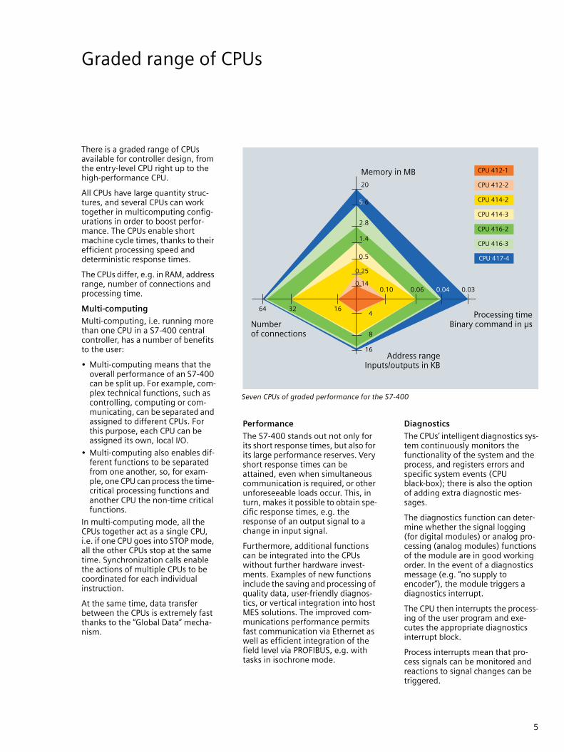
CPU 416-2 CPU 416-3 CPU 417-4
Main memory• integrated• in instructions• for program• for data
2.8 MB460 K1.4 MB1.4 MB
5.6 MB930 K2.8 MB2.8 MB
20 MB3.3 M10 MB10 MB
Load memory• integrated• expandable to
256 KB RAM64 MB
Backup
Number of blocks• FB• FC• DB
204820484095 (DB 0 reserved)
614461448191 (DB 0 reserved)
Program execution• free cycle• timed interrupts• delay interrupts• time interrupts• process interrupts• multi-computing interrupt• startup
1849813
1849813
Execution times• bit operations• word operations• fixed point arithmetic• floating point arithmetic
0.04 µs0.04 µs0.04 µs0.12 µs
0.03 µs0.03 µs0.03 µs0.09 µs
Bit memories/timers/counter• Bit memories• S7 timers/S7 counters• IEC timers/IEC counters
16 KB2048/2048SFB/SFB
Design• Number of expansion units• Num. of DP masters, through CP• Number of FMs• Number of CPs
21max. 10limited by number of slots and number of connectionslimited by number of slots and number of connections
MPI/DP interface• Number of DP slaves• Transmission speed
32max. 12 Mbit/s
DP interfaces• Number• Number of DP slaves• Transmission speed• Interface modules for insertion
1125max. 12 Mbit/s–
2125 eachmax. 12 Mbit/s1 x DP
3125 eachmax. 12 Mbit/s2 x DP
Address ranges• Total I/O address area• I/O process image• Total digital channels• Total analog channels
16 KB/16 KB16 KB/16 KB131072/1310728192/8192
MLFB group 6ES7416-2XK... 6ES7416-3XL... 6ES7417-4XL...

10
The S7-400 is now capable of pro-viding distributed I/O solutions with the capability to handle extremely fast processes with very high preci-sion.
Applications associated with such demands are e.g.
• Motion control
• Synchronism
• Closed-loop controls
• Software-based cam controls
• Measurements at several points
• Speed and flow measurements
Consequently, production can be enhanced while at the same time increasing quality. This was made possible by the new system function denoted "isochrone mode" (not with fault-tolerant CPUs).
This is understood to be the synchro-nous coupling of signal acquisition and output by the distributed I/O sig-nal transmission via PROFIBUS, and program processing at the clock rate of the equidistant PROFIBUS. This results in a system which records its input signals, processes them, and passes on the output signals at con-stant intervals. The S7-400 thus guarantees exactly reproducible and defined process response times as well as equidistant and synchronous signal processing for the distributed I/O.
Exact repeatability of all timing sequences means that even fast pro-cesses can be handled reliably. A comprehensive range of compo-nents is available which supports isochrone mode in order to solve many applications from the motion control, measurement or control sectors.
• The user program is synchronized with the I/O processing. Synchronism means that all process timings are matched to one another, and that all input data are recorded at a defined point in time. In the same manner, the output data become effective at a defined point in time. The input and output data are synchronized accord-ing to the system clock up to the ter-minal. The data of one cycle are always processed in the next cycle.
• The input and output data are pro-cessed equidistant. Equidistance means that input data are always read in at the same intervals, and output data are always output at the same intervals.
• All input and output data are trans-mitted consistently. Consistence means that all data of the process image belong together logically and with respect to time.
Isochrone mode for fast and exact processing
System clock
ET 200
CPU
Distributed automation structure withisochronous and strictly real-time response
The system clock applies to the complete automation structure
10
Features Application
Recording of actual values and output of setpoints are carried out in synchro-nism, i.e. simultaneously for all inputs and all outputs, in order to generate consistent process images.
• Synchronous applications are more exact since the respective positions are measured simultaneously.
• Signals which are close in time can also be spatially distributed using distributed I/Os, e.g. start signals to several units where the time sequence is relevant.
• As a result of recording at the same time and synchronous transmission, the I/O image is consistent. This allows e.g. the generation of a ratio of several analog values (e.g. several pressure values in a press).
Recording of actual values and output of setpoints are carried out equidis-tantly, i.e. always at the same intervals
• Calculations from the difference between actual values, e.g. during speed or flow mea-surements.
• Dosing procedures.• Control loops can also be connected via dis-
tributed I/Os.

11
Changes in configuration in RUN mode
Modifications or expansions of a (partial) plant are also required while in run mode, e.g. to imple-ment new sensors or actuators, or to change the parameters of I/O mod-ules (e.g. selection of other inter-rupt limits).
Such applications are encountered with non-stop requirements, i.e. with continuous processes which cannot be switched off or where the production should not be inter-rupted: process or production plants with high restart costs. SIMATIC S7-400 now allows hard-ware reconfigurations without any adverse effects while in run mode. CiR (Configuration in RUN) allows commissioning and retrofitting while the plant is in full operation. Advantages
• CiR allows plant expansion and optimization. The expansion or conversion of a plant can be carried out without interrupting process operation. These modifications are carried out reaction-free. Expansions and conversions can therefore be carried out cheaper and faster.
• Modifications in run mode also permit a highly flexible response to process changes and process optimizations.
• In addition, the time required for the conversion of plants which are not subject to non-stop require-ments can also be shortened through modification and recon-figuration in run mode, since the plant must not be re-initialized and synchronized when hardware is changed.
Application
Modifications to the hardware con-figuration in run mode are possible with distributed I/Os. All standard CPUs of the S7-400 can be used, as well as the fault-tolerant S7-400H CPUs in non-redundant mode. CiR procedures can be carried out with the following DP masters: • CPU via integral interfaces
• CP 443-5 ext (V5.0 and higher)
• IF 964-DP interface module
S7-400H CPUs with a redundant configuration can be modified in run mode using the H-CiR function.
Functions
The following changes to the hard-ware configuration of a plant can be carried out in run mode:
• Addition of distributed I/O stations (PROFIBUS DP and PROFIBUS PA slaves), e.g. for designing a fur-ther process line
• Addition of I/O modules in the ET 200M I/O system, e.g. to imple-ment additional sensor systems
• Reversal of modifications, i.e. added field devices (DP/PA slaves) and modules can be removed again
• Modification of I/O module parameters in the ET 200M I/O system, e.g. in the case of a spare part when using a sensor with dif-ferent specifications, or for select-ing other interrupt limits
S7-400CPUs
S7-400Hin stand-alone or redundant mode
ET 200M
ET 200M F-modules DP slave PA slave
PA slave
DP/PA link
DP slave DP/PA link
PROFIBUS
PROFIBUS PA
PROFIBUS PA
PROFIBUS
Range of modules which can be addedto or removed from a plant with an
S7-400 as master

12
As a result of the increasing degree of automation of industrial plants, the availability of the used systems is becoming increasingly important. Failures or faults in automation sys-tems result in non-productive and expensive downtimes on the one hand, and in high restart costs on the other. Furthermore, increasing cost pressure result in the desire to operate machines and plants with as few personnel as possible.
Switchover time
As a result of their redundant struc-ture, fault-tolerant automation sys-tems can continue the production process even following a fault. Switching over from the master sys-tem to the backup system is carried out within the so-called switchover time. Depending on the duration of this switchover time, a differentia-tion is made between warm standby (longer switchover time) and hot standby (short switchover time). Downtimes and restart costs can thus be significantly reduced.
Configuration
In the fault-free state, the master controller (station A) controls the fault-tolerant area. The backup con-troller (station B) also has access to this fault-tolerant area. If the master fails, the backup controller takes over control of the fault-tolerant area. The fault-tolerant area is there-fore also available in the event of a fault.
Both controllers can additionally control normal I/Os without increased availability requirements, i.e. a PLC can handle both the nor-mal area and the fault-tolerant area.
The SIMATIC S7-400H is a PLC with two fault-tolerant CPUs of the same type, where a switch is made from the master system to the backup sta-tion in the event of a fault. It is suit-able for fault-tolerant processes with hot standby requirements (pro-cesses with switchover times shorter than 100 ms).
Synchronization
The method of event-controlled syn-chronization permits fast, bumpless switchover to the redundant CPU in the event of a fault. This CPU then continues processing from the point of interruption without loss of infor-mation or interrupts. The operating system guarantees that all com-mands whose execution would result in different statuses in the two systems are executed in synchro-nism. This is achieved without the user having to carry out any pro-gramming or parameter settings.
Fault-tolerant S7-400H PLC
Fault-tolerant SIMATIC S7-400H

13
Fail-safe S7-400F/FH PLC
SIMATIC Safety Integrated com-prises the fail-safe SIMATIC PLCs as well as I/Os and engineering within the product range of Safety Inte-grated. When a fault occurs, the application can be transferred as required to a safe state or held in an existing safe state. These fail-safe PLCs are based on the proven stan-dard PLCs.
The PROFIBUS has been expanded by the PROFIsafe profile for safety-relevant communications.
Thus safety-relevant and standard communication are possible over just one standard PROFIBUS cable.
The engineering for the standard and safety functions of these fail-safe SIMATIC PLCs is carried out using the same configuration tools (STEP® 7). In a SIMATIC PLC, the safety technology is thus integrated seamlessly into the standard auto-mation. As a result of the fine-modular design of the fail-safe I/O, safety technology need only be used where it is actually required. A com-bined design with safety and stan-dard components is easy - as is the coexistence of safety-relevant and standard programs in one PLC.
Standard and safety-relevant data are transmitted on the same bus cable using PROFIsafe
Production automation
The CPU 416F of the S7-400 has been designed for production auto-mation. It is based on the associated standard CPU whose hardware and operating system have been expanded to execute safety pro-grams and various protective mea-sures. All programming of the safety-rele-vant program is carried out with STEP 7 in the standard LAD and FBD languages. The software package "Distributed Safety" supports parameterization of the fail-safe I/O and programming by means of predefined, certified software blocks.
Process automation
The fault-tolerant CPUs 414H and 417H of the S7-400 are available for use in the process industry. Safety-relevant applications in the process industry require a special software package "S7 F-Systems". Fail-safe applications with SIL 3 can be solved with one CPU.
Two redundant CPUs can be used for enhanced system availability in order to comply with the demands for fail-safety and fault-tolerance.
Drafting of the program is carried out using the Safety Matrix or Con-tinuous Function Chart (CFC) as well as certified function blocks.
"S7 F-Systems" supports configura-tion of the safety-relevant I/O and programming of the logic functions.
Fail-safedata
Fail-safedata
Standarddata
Standarddata
PROFIsafe
StandardPROFIBUS DPprotocol
StandardPROFIBUS DPprotocol
PROFIsafe PROFIsafelayer
StandardPROFIBUS
PROFIBUS
Fail-safe and fault-tolerant SIMATIC S7-400F/FH

14
The basis for configuration and pro-gramming of the SIMATIC S7-300, S7-400, C7 and WinAC is STEP 7. This uniformity makes it possible to transfer applications to different platforms.
STEP 7
STEP 7 offers functions for every phase of an automation project – from configuration to startup, test-ing and servicing, and thus supports the complete engineering workflow.
STEP 7 incorporates both the hard-ware configuration of the plant and the parameterization of the mod-ules, so there are no more hardware settings to be made. Using STEP 7, the communications links within a project are defined on a GUI. The SIMATIC Manager for STEP 7 is the central tool for project manage-ment. The SIMATIC Manager not only provides a view of a CPU but also of the complete plant irrespec-tive of the number of PLCs, drives and HMI units present in the solu-tion.
For development of the user pro-gram, STEP 7 includes three basic languages: statement list (STL), lad-der diagram (LAD) and function block diagram (FBD). These are stan-dardized according to IEC 1131-3 and used globally as the interna-tional standard.
STEP 7 Professional
STEP 7 Professional is recommend-able for larger applications. This package includes all programming languages standardized according to IEC 1131-3, i.e. in addition to statement list (STL), ladder diagram (LAD) and function block diagram (FBD):
• S7-SCL (Structured Control Lan-guage), the PASCAL-based higher-level language for pro-gramming complex algorithms and mathematical functions or for tasks associated with data pro-cessing.
• S7-GRAPHenables graphical configuration of sequential control systems. S7-GRAPH is used to describe sequential operations with alter-native or parallel step sequences.
• S7-PLCSIMfor simulation of a test environ-ment including PLC and process. S7-PLCSIM enables testing of the program before it is loaded into the plant’s PLC.
Further engineering tools
Further engineering tools are avail-able for special applications, for example:
• S7-HiGraphfor automation of function units with status diagrams. This method is used to graphically describe statuses and step criteria.
• CFC (Continuous Function Chart), the technology-oriented diagram which enables graphical intercon-nection of complex functions, for example in process engineering.
Data storage
The Memory Card allows user pro-grams and any data to be saved to the CPU. If you are servicing or upgrading the system, this provides the advantage that the personnel can still access the currently exe-cuted programs as well as the whole project, including any comments and symbols on site. If you are using higher-level languages or graphical engineering tools, the program source code is also immediately available in its original form or in graphical format. Last but not least, it is also possible to save customer-specific operating instructions, manuals and machine documenta-tion directly on the CPU in all stan-dard file formats.
Configuration and programming with STEP 7
Graphic configuration of communication links in NetPro

15
Communications networks – Ethernet, PROFIBUS and more
The following bus systems are avail-able for SIMATIC:
• Industrial Ethernet (IEEE 802.3 and 802.3u) – the international standard for area and cell network-ing is the number one in the global LAN landscape with a share of more than 80%. Industrial Ether-net can be used to design power-ful communications networks covering a wide area.
• PROFINET – the international stan-dard uses Industrial Ethernet, and permits real-time communication down to the field level. With full utilization of existing IT standards, PROFINET also permits isochro-nous motion control applications on the Industrial Ethernet.
• PROFIBUS (IEC 61158 / EN 50170) – the international standard for the cell and field levels is the glo-bal leader for fieldbuses. It is the only fieldbus which permits com-munication in both production-oriented and process-oriented applications.
• As a low-price alternative to a cable harness, the AS-Interface links sensors and actuators by means of a two-wire cable.
• The basis for building services automation is the worldwide stan-dard KNX (EN 50090, ANSI EIA 776).
• Point-to-point connection – the simplest form of communication between two stations. Special pro-tocols are used, e.g. RK 512, 3964(R), ASCII, (see page 19).
• Routers are implemented using controllers or links. Communications options of the SIMATIC S7-400
KNX AS-Interface
PROFIBUS
MPI
IndustrialEthernet (PROFINET)
S7-300S7-400
PC
OS
OS
Proxy, e.g. S7-300 with CPU 317-2 PN/DP
ET 200S PN
S7-400PG Scanner
S7-300ET 200
Link
ET 200S
Fire detector Sensor

16
! !"#
"#
$ %
&% ! %
"'() "#
* +,- '. -
'. -
/0 % & ' ! ". !!
% !% %% ! $$% % $!
&%!% & $ & 1# "2! !
" &$ 0 & & +& $
PROFINET – the open Industrial Ethernet standard
Uniform communication from the field level up to the operations man-agement level is currently one of the most important demands placed on automation technology. Standard-ized connection systems, uniform network management, IT access mechanisms and comprehensive diagnostics facilities permit savings to be made covering planning, com-missioning and operation. It should be possible to use the advantages of the rugged fieldbuses as well as the standardized IT functionality of Eth-ernet for the uniform communica-tion. With PROFINET, PROFIBUS International (PI) has defined a com-prehensive standard which opens up new possibilities for the field area:
• IT integration
• Distributed automation
• Use of industrial wireless LAN
• Real-time
PROFINET is the open and cross-ven-dor Industrial Ethernet standard for all automation levels and applica-tions.
PROFINET IO
PROFINET IO is used to directly link distributed field devices to Industrial Ethernet. In the proven configura-tion with STEP 7 known from PROFI-BUS, these field devices (IO device) are assigned to a central controller (IO controller).
In order to provide safeguarding of investments, existing modules or devices can be used further with PROFINET-capable interfaces or links. An IO supervisor is used for HMI and diagnostics purposes (over-view and detailed diagnostics).
The following products from the S7-400 environment are available, and can be configured using STEP 7:
• IM 151-3 PN: direct connection of ET 200S as IO device to Industrial Ethernet
• CP 443-1 ADVANCE: communica-tions module for expansion of the S7-400 by an Industrial Ethernet interface in order to connect field devices as IO device to Industrial Ethernet via S7-400
PROFINET - the main topics
PROFINET IO with distributed field devices

17
Powerful networking –via integral interfaces
The S7-400 provides a connection to all standard bus systems.
Connection of sensors/actuators to the S7-400 is supported by PROFIBUS DP and PROFINET IO. To make this possible, the S7-400 can be connected as a master - either by means of the interface integrated into each CPU, a special interface module or a communications pro-cessor (CP).
The AS Interface and KNX networks and other bus systems are accessible from the S7-400 through the PROFIBUS gateways.
Data transfer to other automation systems or intelligent partners (PC, computer, etc.) is implemented via the MPI interface, PROFIBUS or Industrial Ethernet. The MPI inter-face on each CPU enables simple cyclic data transfer on the one hand (no acknowledgment) and pro-grammed transfer of relatively large volumes of data on the other (with or without acknowledgment). Spe-cific communications processors (CP) are used for the connection to PROFIBUS, PROFINET or Industrial Ethernet.
A point-to-point coupling via PtP CPs is used for simple communications tasks.
Integral interfaces
Interfaces directly integrated in the CPUs permit the design of a power-ful communications landscape with application of standard bus technol-ogy, e.g. for HMI and programming device functions. Sufficient connec-tion resources are available to per-mit the connection of many HMI devices. Using a routing function, a programming device connected at any position of the network can access all stations of the network.
Multipoint interface MPI
MPI is the low-cost solution for com-munication with programming devices/PCs, HMI systems and fur-ther SIMATIC S7/C7/WinAC automa-tion systems. Max. 125 MPI stations can be connected at up to 12 Mbit/s, e.g. for exchanging process data between different PLCs or for HMI tasks without programming over-head. The MPI can also be used as a PROFIBUS DP interface, and permits the configuration of a further DP segment.
PROFIBUS DP
The economical design of larger dis-tributed structures is possible by connecting the SIMATIC S7-400 to the open PROFIBUS DP fieldbus (IEC 61158 / EN 50170). This opens up communications possibilities to a large number of partners, from the SIMATIC PLC right up to field devices from other vendors. Communica-tion with existing SIMATIC S5 or SIMATIC 505 systems is possible. Configuration of the distributed I/O is carried out using STEP® 7 as with the central I/O, thus saving engi-neering overhead.
Supporting of the DP V1 functional-ity permits parameterization and optimization of field devices during runtime and thus shorter machine setup times. Detailed device diag-nostics additionally reduces the plant downtimes.
Communications interface modules
Communications interface modules can be optionally used in the S7-400 CPUs in order to adapt these to the requirements of the respective application.
For this purpose, the CPUs 414-3 and 416-3 have one vacant slot, and the CPU 417 has two vacant slots. By adding such interface modules, additional DP segments can be designed as master or slave whose functionality corresponds to that of the integral interface.
Powerful networking with integral interfaces of CPU and communications processor

18
Versatile module spectrum
The versatile module spectrum per-mits modular adaptation of the SIMATIC PLC to highly different tasks.
The following are available:• Signal modules (digital and ana-
log I/O modules) for almost all types of signal, also with interrupt processing and diagnostics
• Function modules for technologi-cal tasks, e.g. counting/measure-ment, all types of positioning functions, cam control and com-puting
• Communications modules for serial point-to-point connections and the connection of networks, e.g. PROFIBUS, PROFINET, Indus-trial Ethernet with IT functionality
• Load power supplies to secure the supply of all operating voltages for the other modules (but not the load voltages for signal modules)
• Interface modules for connecting racks in the case of a multi-tier design.
Signal modules
However, the S7-400 signal mod-ules only represent a subset of the modules which can be connected to the S7-400 via PROFIBUS DP. Hot swapping of signal modules inserted in the central controller is possible.
Criteria are presented on the follow-ing pages which permit selection of the appropriate signal module for a respective application.
Comprehensive and continuously updated technical specifications can be found in the interactive Catalog CA 01 on the Internet:
www.siemens.com/automation/ca01
Function modules
Function modules are available for the following technological applica-tions:• Counting in various modes, up to
500 kHz
• Cam control for up to 16 cam lines per module
• Any type of positioning function: controlled positioning using the rapid/creep feed process (3 axes per module)
• Point-to-point positioning and velocity profiles (position control) with stepper and servo motors (3 axes per module)
• PID controller with backup func-tionality and integrated online self-configuration for various types of controller (continuous controllers, stepper controllers, pulse controllers)
• Freely programmable highly dynamic controller for up to 100 axes per module
Communications
Communications modules are avail-able for the following applications:• Point-to-point connection with
data rates of up to 115 Kbit/s and various protocols, e.g. for con-necting modems, printers, scan-ners, drives, external devices, etc.
• Connection to PROFIBUS using either the DP or the FMS protocol (DP V0 and DP V1)
• Connection to Industrial Ethernet using the ISO/TCP or TCP/IP data communications protocol and PROFINET
• Connection to the Internet through Ethernet for loading Web sites and using e-mail
Power supplies
The power supplies are also avail-able in a version with diagnostics capability, and can be provided with a redundant design if necessary to increase the PLC availability.
Interfacing to the IT world
The SIMATIC permits simple inter-facing of the modern IT world to the automation technology. The follow-ing functions are possible using the plug-in IT-CP:
• Creation of your own Web sites using any HTML tools, and the process variables for the S7 can simply be assigned to the HTML objects.
• Monitoring of the S7 through these Web sites using a standard browser.
• Sending of e-mails from the user program of the S7 by means of function calls.
• Remote programming through the telephone network (e.g. ISDN) using the WAN properties of TCP/IP.

19
3 ,!
!$
"#*'1."#1'
!!
'.$
10
Cost-effective point-to-point coupling
Point-to-point coupling using com-munications processors (CPs) is a very powerful and cost-effective alternative to bus systems.
The advantage of a point-to-point coupling compared to bus systems is particularly evident if only a few (RS 485) devices are to be con-nected to the SIMATIC S7.
The CPs can also link third-party sys-tems to the SIMATIC S7 cost-effec-tively. Because of the greater flexi-bility of the CPs, it is possible to implement different physical trans-mission systems, transmission rates or even customized transmission protocols.
The CPs have a rugged plastic hous-ing with LEDs for display of operat-ing states and faults.
A configuration package is available on CD for each CP with electronic manual, parameterization screen forms, and standard function blocks for communication between the CPU and CP.
The configuration data are stored in a system data block which is saved in the CPU. Following replacement of a module, the new module is therefore immediately ready for operation.
With the S7-400 point-to-point cou-pling modules, adaptation to the physical transmission system is car-ried out by plugging in correspond-ing interface modules without the use of external converters.
Communications facilities of the SIMATIC S7-400
Technical specifications of the S7-400 point-to-point CPs
Application Fast response with small data quantities
Coupling
Low-cost with one variable interface
High-speedwith two variable interfaces
Transmission rate High (115200 bit/s) Low (38400 bit/s) High (115200 bit/s)
Loadable proto-cols
– Modbus master(6ES7 340-1AA..-...)
Modbus slave(6ES7 340-1AB..-...)
Data highway(6ES7 340-1AE..-...)
Module CP440 CP 441-1 CP 441-2
MLFB group:6ES7 440 -1.... 441-1.... 441-2....
Physical transmis-sion system• RS 232C (V.24)• 20 mA (TTY)• RS 422/485 (X.27)
––Yes (up to 32 stations)
All transmission systems, all interface modules, plug-in, serial
Integral transmis-sion protocols• ASCII• Printer drivers• 3964(R)• RK512
–
–
–

20
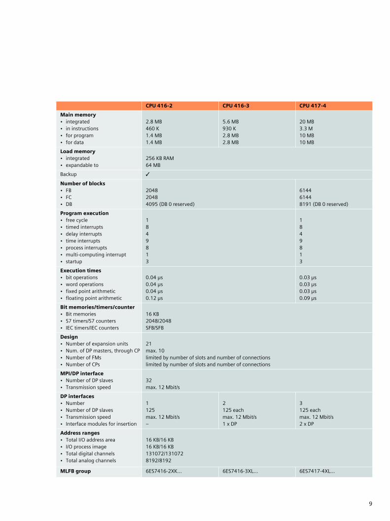
Signal modules for sensors and actuators
Signal modules are the interface of the PLC to the process. A wide range of different digital and analog mod-ules make those I/Os available which are required for the respective task.
Easy to install
The sensors/actuators simply con-nect to the front connector. When replacing the module, all you need to do is plug the connector into the new module of the same type. You do not need to change the wiring. The coding of the front connector prevents confusing of modules.
Fast connection
Using SIMATIC TOP connect makes it even easier to connect (not for the onboard I/Os of the S7-300 compact CPUs). You can choose between prewired front connectors with indi-vidual strands and a completely modular building block system, con-sisting of front connector module, cable and terminal block.
High level of packaging density
The large number of channels on the modules is one reason for the space-saving design, e.g. modules are available with 8 to 32 digital channels.
Simple to configure
The modules are configured and parameterized using STEP 7, there are no fiddly switch settings. The data are stored centrally and auto-matically transferred to the new module after a module is replaced, which prevents setting faults. No software upgrade is required when new modules are installed. Configu-rations which have been carried out once, e.g. for series machines, can be identically repeated as often as required.
Diagnostics, interrupts
Many modules also monitor signal acquisition (diagnostics interrupt) and the signals from the process (process interrupt, e.g. evaluation of edges). This means the system can react quickly to any irregularities and to every process event. How and whether the controller reacts can be configured in STEP 7. For the digital input modules, several interrupts are also possible per module.
Parameterization of an analog input module
21
Module type Digital inputs
Special features of this module
Very fast, inter-rupt-capable 24 V DC input module
24 V DC standard in-put module – ex-tremely high packag-ing density
Highest packaging density for the 120 V market
Input module for higher, variable volt-ages
Interrupt-capable input module for lower, variable volt-ages 1)
Type of voltage DC AC/DC
Input voltage 24 V 120 V 120/230 V 24 to 60 V
Interrupt capability –
Input delay 0.05 to 3 ms 2) 3 ms < 25 ms 0.5 to 20 ms 2)
Num. of channels 16 32 16
MLFB group:6ES7 421- 7BH -... 1BL..-... 1EL..-...
1FH..-...
7DH..-...
Module type Digital outputs
Special features of this module
DC output module for high currents
24 V DC standard output module – highest possible packaging density
Very fast, interrupt-capable 24 V DC input module
AC standard output module
Relay output module
Type of voltage DC AC Relay
Output voltage 24 V 120/230 V 5-125 V DC
Output current 2 A 0.5 A 2 A 5 A
Interrupt capability – –
Num. of channels 16 32 16
MLFB group:6ES7 422- 1BH..-... 1BL..-... 7BL..-...
1FH..-... 1HH..-...
1) can also be used as an active low module2) can be set with parameters
I/Os –selection guide for digital inputs/outputs

22
I/Os –selection guide for analog inputs
Module type Analog inputs
Physical variable Voltage
Special features of this module
Standard module with 16 inputs
Standard module with 8 inputs
Numerous voltage ranges
Very rapid analog value acquisition
Generation of diagnostics and process value interrupts at 16 bit resolu-tion
Channel-oriented isola-tion and gener-ation of diagnostic and process value interrupts
Measurement rangeEncoder
±1 V1 - 5 V
±1 V±10 V1 - 5 V
±80 mV±250 mV±500 mV±1 V±2,5 V±5 V±10 V1 - 5 V
±1 V1 - 5 V±10 V
±25 mV±50 mV±80 mV±250 mV±500 mV±1 V±2.5 V±5 V±10 V1 - 5 V
±25 mV±50 mV±80 mV±250 mV±500 mV±1 V±2.5 V±5 V±10 V1 - 5 V
Interrupt capability –
Isolation –
Number of channels 16 8 16 8
Resolution 13 bit 14 bit 16 bit
Conversion time per channel
55/65 ms 23/25 ms 20/23 ms 52 µs 6/21/23 ms –
MLFB group 6ES7 431- 0HH.-....
6ES7 431- 1KF0.-....
6ES7 431- 1KF1.-....
6ES7 431- 1KF2.-....
6ES7 431- 7QH.-....
6ES7 431- 7KF0.-....
Module type Analog inputs
Physical variable Current
Special features of this module
Standard module with 16 inputs
Standard module with 8 inputs
Standard module with 8 inputs
Very rapid analog value acquisition
Generation of diagnostics and process value interrupts at 16 bit resolution
Channel-oriented isola-tion and generation of diagnostic and process value interrupts
Measurement rangeEncoder
4-20 mA±20 mA
4 - 20 mA±20 mA
4 - 20 mA0 - 20 mA
4 - 20 mA±20 mA
4 - 20 mA0 - 20 mA±5 mA±10 mA±20 mA
4 - 20 mA0 - 20 mA±5 mA±10 mA±20 mA±3.2 mA
Interrupt capability –
Isolation –
Number of channels 16 8 16 8
Resolution 13 bit 14 bit 16 bit
Conversion time per channel
55/65 ms 23/25 ms 20/23 ms 52 µs 6/21/23 ms –
MLFB group 6ES7 431- 0HH.-....
6ES7 431- 1KF0.-....
6ES7 431- 1KF1.-....
6ES7 431- 1KF2.-....
6ES7 431- 7QH.-....
6ES7 431- 7KF0.-....

23
I/Os –selection guide for analog inputs
Module type Analog inputs
Physical variable Resistance
Special features of this module
Standard module Numerous measurement ranges
High-speed analog value acquisition and generation of process interrupts
Many measurement ranges and generation of process and diagnos-tics interrupts
Encoder measurement range
0 - 600 Ω 0 - 48 Ω, 0 - 150 Ω,0 - 300 Ω, 0 - 600 Ω, 0 - 6000 Ω
0 - 600 Ω 0 - 48 Ω, 0 - 150 Ω0 - 300 Ω, 0 - 600 Ω, 0 - 6000 Ω
Interrupt capability –
Isolation
Number of channels 4 8
Resolution 13 bit 14 bit 16 bit
Conv. time per channel 23/25 ms 20/23 ms 52 µs 6/21/23 ms
MLFB group 6ES7 431-1KF0.-.... 6ES7 431-1KF1.-.... 6ES7 431-1KF2.-.... 6ES7 431-7QH.-....
Module type Analog inputs
Physical variable Thermocouples
Special features of this module
Standard module with 8 channels 16 channels with 16 bit resolu-tion and generation of process and diagnostics interrupts
Channel-oriented isolation and generation of process and diagnostics interrupts
Types B, E, N, J, K, L, R, S, T, U
Interrupt capability –
Isolation
Number of channels 8 16 8
Resolution 14 bit 16 bit
Conv. time per channel 20/23 ms 6/21/23 ms –
MLFB group 6ES7 431-1KF1.-.... 6ES7 431-7QH.-.... 6ES7 431-7KF0.-....
Module type Analog inputs
Physical variable Resistance thermometer
Special features of this module
Standard module with 4 channels Generation of process and diagnostics interrupts
Generation of process and diagnostics interrupts
Types Pt 100, Pt 200, Pt 500, Pt 1000,Ni 100
Pt 100, Pt 200, Pt 500, Pt 1000, Ni 100, Ni 1000
Interrupt capability –
Isolation
Number of channels 4 8
Resolution 14 bit 16 bit
Conv. time per channel 20/23 ms 6/21/23 ms –
MLFB group 6ES7 431-1KF1.-.... 6ES7 431-7QH.-.... 6ES7 431-7KF1.-...

24
I/Os – selection guide for analog outputs, standards
Module type Analog outputs
Physical measured variable Voltage, current
Encoder measurement range ±10 V, 0 - 10 V, 1 - 5 V,±20 mA, 0 - 20 mA, 4 - 20 mA
Interrupt capability –
Isolation
Number of channels 8
Resolution 13 bit
Conversion time per channel 420 µs
MLFB group 6ES7 432-1HF..-....
Standards
The SIMATIC S7-400 fulfills the following national and interna-tional standards:
• DIN, EN, IEC
• UL certificate
• CSA certificate
• FM class 1 div. 2; group A, B, C and D
• Temperature group T4 (≤ 135 °C)
• Marine approvals from
– American Bureau of Shipping
– Bureau Veritas
– Des Norske Veritas
– Germanischer Lloyd
– Lloyds Register of Shipping
• Ambient temperature 0 to 60 °C for all components
• Earthquake-proof
Siemens AGAutomation and Drives
Postfach 484890327 NÜRNBERGFEDERAL REPUBLIC OF GERMANY
Order No.: 6ZB5310-0JD02-0BB1Printed in the Federal Republic of Germany26100/501345 KB 0305 6. ROT En
© Siemens AG 2005Subject to change without prior notice
www.siemens.com/simatic-s7-400
The information provided in this bro-chure contains descriptions or character-istics of performance which in case ofactual use do not always apply as de-scribed or which may change as a resultof further development of the products.
An obligation to provide the respectivecharacteristics shall only exist if expresslyagreed in the terms of contract. Availabil-ity and technical specifications are sub-ject to change without notice.
All product designations may be trade-marks or product names of Siemens AGor supplier companies whose use bythird parties for their own purposescould violate the rights of the owners.
You can find more detailed informationin the SIMATIC Guide documentation:
You can order further documents onthe topic of SIMATIC at:
To arrange a personal discussion youcan find your local contact at:
In the A&D Mall you can place ordersdirectly via the Internet:
www.siemens.com/simatic-docu
www.siemens.com/simatic/printmaterial
www.siemens.com/automation/partner
www.siemens.com/automation/mall
Product briefs on further versions of the S7-400 for special applica-tions
Fail-safe SIMATIC PLCs6ZB5310-0KE01-0BA.
Fault-tolerant SIMATIC PLCs6ZB5310-0FW01-0BA.
Technological tasks with SIMATICE20001-A430-P210
WinAC PC-based6ZB5310-0KP01-0BA.
Isochrone mode6ZB5310-0KV01-0BA.
AS-InterfaceE20001-A150-P302
Industrial Ethernet6ZB5530-0AK01-0BA.
PROFINET6ZB5310-0MA01-0BA0
PROFIBUS6ZB5530-0AQ01-0BB.