Embed Size (px)
Citation preview
Part A – General ApplicationA
Part B – CP Descriptions
CP 342–5 / CP342–5 FOOrder no.: 6GK7 342–5DA02–0XE0 /Order no.: 6GK7 342–5DF00–0XE0(C79000–G8976–C146–05)
B1
CP 343–5Order no.: 6GK7 343–5FA01–0XE0(C79000–G8976–C160–03)
B2
CP 443–5 BasicOrder no.: 6GK7 443–5FX01–0XE0(C79000–G8976–C161–03)
B3
CP 443–5 ExtendedOrder no.: 6GK7 443–5DX03–0XE0(C79000–G8976–C162–04)
B4
SIMATIC NET
S7-CPs for PROFIBUS
Manual
Release 2/2003C79000-G8976-C154-04
A–2S7-CPs for PROFIBUS / Manual Part A – General Section
Release 2/2003
C79000-G8976-C154-04
Classification of Safety-Related NoticesThis manual contains notices which you should observe to ensure your own perso-nal safety, as well as to protect the product and connected equipment. These noti-ces are highlighted in the manual by a warning triangle and are marked as followsaccording to the level of danger:
!Danger
indicates that death or severe personal injury will result if proper precautions arenot taken.
!Warning
indicates that death or severe personal injury can result if proper precautions arenot taken.
!Caution
with warning triangle indicates that minor personal injury can result if properprecautions are not taken.
Vorsicht
without warning triangle indicates that damage to property can result if properprecautions are not taken.
Notice
indicates that an undesirable result or status can result if the relevant notice isignored.
Note
highlights important information on the product, using the product, or part of thedocumentation that is of particular importance and that will be of benefit to theuser.
A–3S7-CPs for PROFIBUS / Manual Part A – General SectionRelease 2/2003
C79000-G8976-C154-04
Trademarks
SIMATIC�, SIMATIC HMI� and SIMATIC NET� are registered trademarks ofSIEMENS AG.
Third parties using for their own purposes any other names in this document whichrefer to trademarks might infringe upon the rights of the trademark owners.
Safety Instructions Regarding your Product:
Before you use the product described here, read the safety instructions below tho-roughly.
Qualified Personnel
Only qualified personnel should be allowed to install and work on this equipment.Qualified persons are defined as persons who are authorized to commission, toground, and to tag circuits, equipment, and systems in accordance with establis-hed safety practices and standards.
Correct Usage of Hardware Products
Note the following:
!Warning
This device and its components may only be used for the applications described inthe catalog or the technical description, and only in connection with devices orcomponents from other manufacturers which have been approved orrecommended by Siemens.
This product can only function correctly and safely if it is transported, stored, setup, and installed correctly, and operated and maintained as recommended.
Before you use the supplied sample programs or programs you have writtenyourself, make certain that no injury to persons nor damage to equipment canresult in your plant or process.
EU Directive: Do not start up until you have established that the machine on whichyou intend to run this component complies with the directive 89/392/EEC.
Correct Usage of Software Products
Note the following:
!Warning
This software may only be used for the applications described in the catalog or thetechnical description, and only in connection with software products, devices, orcomponents from other manufacturers which have been approved orrecommended by Siemens.
Before you use the supplied sample programs or programs you have writtenyourself, make certain that no injury to persons nor damage to equipment canresult in your plant or process.
A–4S7-CPs for PROFIBUS / Manual Part A – General Section
Release 2/2003
C79000-G8976-C154-04
Prior to Startup
Prior to startup, note the following:
Caution
Prior to startup, note the information and follow the instructions in the latest docu-mentation. You will find the ordering data for this documentation in the relevantcatalogs or contact your local Siemens office.
We have checked the contents of this manual for agreement with the hardwa-re and software described. Since deviations cannot be precluded entirely, wecannot guarantee full agreement. However, the data in this manual are revie-wed regularly and any necessary corrections included in subsequent edi-tions. Suggestions for improvement are welcomed.
Disclaimer of LiabilityCopyright � Siemens AG 2001/2002 All rights reserved
The reproduction, transmission or use of this document or its contents is notpermitted without express written authority. Offenders will be liable fordamages. All rights, including rights created by patent grant or registration ofa utility model or design, are reserved.
Siemens AGAutomation and DrivesIndustrial CommunicationPostfach 4848, D-90327 Nuernberg Technical data subject to change.
Siemens Aktiengesellschaft C79000-G8976-C154 - 03
A–5S7-CPs for PROFIBUS / Manual Part A – General SectionRelease 2/2003
C79000-G8976-C154-04
This SIMATIC NET PROFIBUS CP Manual...
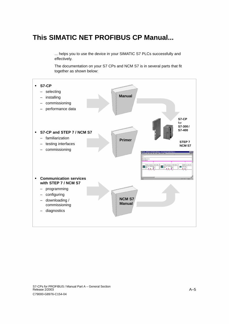
... helps you to use the device in your SIMATIC S7 PLCs successfully andeffectively.
The documentation on your S7 CPs and NCM S7 is in several parts that fittogether as shown below:
� S7-CP
– selecting
– installing
– commissioning
– performance data
� S7-CP and STEP 7 / NCM S7
– familiarization
– testing interfaces
– commissioning
� Communication serviceswith STEP 7 / NCM S7
– programming
– configuring
– downloading /commissioning
– diagnostics
Manual
Primer
NCM S7Manual
STEP 7NCM S7
S7-CPforS7-300 /S7-400
This SIMATIC NET PROFIBUS CP Manual...
A–6S7-CPs for PROFIBUS / Manual Part A – General Section
Release 2/2003
C79000-G8976-C154-04
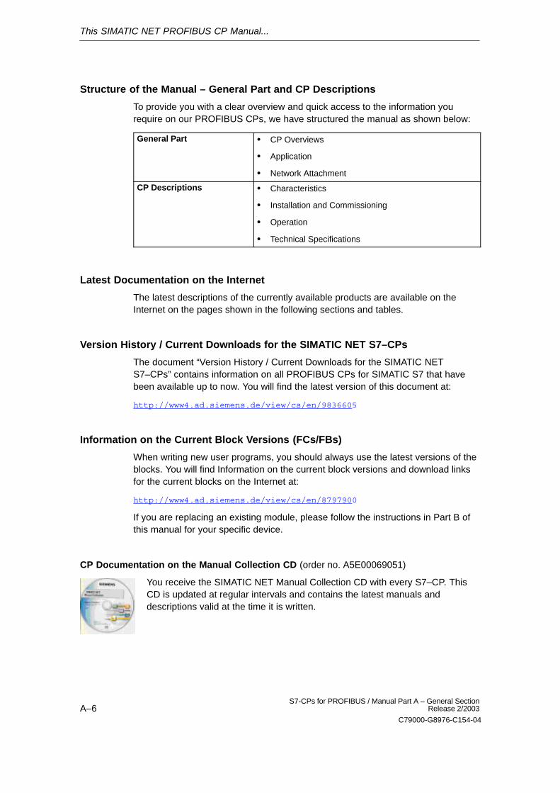
Structure of the Manual – General Part and CP Descriptions
To provide you with a clear overview and quick access to the information yourequire on our PROFIBUS CPs, we have structured the manual as shown below:
General Part � CP Overviews
� Application
� Network Attachment
CP Descriptions � Characteristics
� Installation and Commissioning
� Operation
� Technical Specifications
Latest Documentation on the Internet
The latest descriptions of the currently available products are available on theInternet on the pages shown in the following sections and tables.
Version History / Current Downloads for the SIMATIC NET S7–CPs
The document “Version History / Current Downloads for the SIMATIC NETS7–CPs” contains information on all PROFIBUS CPs for SIMATIC S7 that havebeen available up to now. You will find the latest version of this document at:
http://www4.ad.siemens.de/view/cs/en/9836605
Information on the Current Block Versions (FCs/FBs)
When writing new user programs, you should always use the latest versions of theblocks. You will find Information on the current block versions and download linksfor the current blocks on the Internet at:
http://www4.ad.siemens.de/view/cs/en/8797900
If you are replacing an existing module, please follow the instructions in Part B ofthis manual for your specific device.
CP Documentation on the Manual Collection CD (order no. A5E00069051)
You receive the SIMATIC NET Manual Collection CD with every S7–CP. ThisCD is updated at regular intervals and contains the latest manuals anddescriptions valid at the time it is written.
This SIMATIC NET PROFIBUS CP Manual...
A–7S7-CPs for PROFIBUS / Manual Part A – General SectionRelease 2/2003
C79000-G8976-C154-04
The Documentation Package NCM S7 for PROFIBUS
The paper versions of the CP descriptions are included in the NCM S7 forPROFIBUS manual package. The table below provides you with an overview of thecontents.
Title Content
S7-CPs for PROFIBUS
Manual
The manual S7 CPs for PROFIBUS contains information on the characteristicsof the CPs and instructions on installation and connections.
This is available on the Internet at:
� General Section:http://www4.ad.siemens.de/view/cs/de/8777865
� CP 342-5/342-5 FO:http://www4.ad.siemens.de/view/cs/de/8773570
� CP 343-5:http://www4.ad.siemens.de/view/cs/de/8778841
� CP 443-5 Basic:http://www4.ad.siemens.de/view/cs/de/8776422
� CP 443-5 Extended:http://www4.ad.siemens.de/view/cs/de/8777196
You will find a current version history for S7-CPs at:
http://www4.ad.siemens.de/view/cs/de/9836605
NCM S7 forPROFIBUS, Primer
Based on simple examples, the primer introduces you to the methods ofconnecting and networking SIMATIC S7 stations with CPs on PROFIBUS. Youwill see how the communication calls in the user program should appear tomake optimum use of the services with S7 communication, via theSEND/RECEIVE interface, and the services of the distributed I/Os.
You will learn how simple it is to create a configuration for standardapplications using STEP 7 and the NCM S7 optional package.
The examples described here can also be found in the project folder forsample programs after you have installed STEP 7 and the NCM S7 forPROFIBUS option!
This is available on the Internet at:
http://www4.ad.siemens.de/view/cs/de/1157760
NCM S7 for PROFIBUSVolume 1
The manual is intended as a guide and reference work for configuring andprogramming a PROFIBUS CP.
When working with the configuration software, you can also call up the onlinehelp in specific situations.
This is available on the Internet at:
http://www4.ad.siemens.de/view/cs/de/1158693
This SIMATIC NET PROFIBUS CP Manual...
A–8S7-CPs for PROFIBUS / Manual Part A – General Section
Release 2/2003
C79000-G8976-C154-04
Title Content
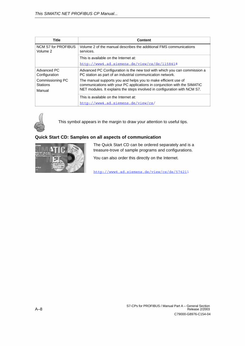
NCM S7 for PROFIBUSVolume 2
Volume 2 of the manual describes the additional FMS communicationsservices.
This is available on the Internet at:
http://www4.ad.siemens.de/view/cs/de/1158418
Advanced PCConfiguration
Commissioning PCStations
Manual
Advanced PC Configuration is the new tool with which you can commission aPC station as part of an industrial communication network.
The manual supports you and helps you to make efficient use ofcommunications with your PC applications in conjunction with the SIMATICNET modules. It explains the steps involved in configuration with NCM S7.
This is available on the Internet at:
http://www4.ad.siemens.de/view/cs/
This symbol appears in the margin to draw your attention to useful tips.
Quick Start CD: Samples on all aspects of communication
The Quick Start CD can be ordered separately and is atreasure-trove of sample programs and configurations.
You can also order this directly on the Internet.
http://www4.ad.siemens.de/view/cs/de/574211
This SIMATIC NET PROFIBUS CP Manual...
A–9S7-CPs for PROFIBUS / Manual Part A – General SectionRelease 2/2003
C79000-G8976-C154-04
Additional Information on SIMATIC S7 and STEP 7
The following documentation contains additional information about the STEP 7standard software of the SIMATIC programmable controllers and can be obtainedfrom your local Siemens office.
Topic Document
Basic information for technical personnelusing the STEP 7 standard software forcontrol tasks with S7-300/400programmable controllers.
STEP 7 basics with
� Configuring hardware with STEP 7
� Programming manual
� Manual for converting from S5 to S7
� Getting Started
The reference works describing theprogramming languages LAD/FBD and STLas well as the standard and systemfunctions in addition to the STEP 7 basicknowledge.
STEP 7 reference manuals with
� Manuals for LAD/FBD/STL
� Standard and System Functions forS7-300/400
You will also find information on the SIMATIC programmable controllers on theQuick Start CD and in the Customer Support online services at:
http://www.ad.siemens.de/net general information
or
http://www.ad.siemens.de/csi/net product information and downloads
Contents
A–10S7-CPs for PROFIBUS / Manual Part A – General Section
Release 2/2003
C79000-G8976-C154-04
Contents
Contents – Part A
1 Introduction A–12. . . . . . . . . . . . . . . . . . . . . . . . . . . . . . . . . . . . . . . . . . . . . . . . . . . . . . . . . . . .
1.1 The Communication Services of the PROFIBUS CPs A–12. . . . . . . . . . . . . . . .
1.2 How to Commission a PROFIBUS CP A–14. . . . . . . . . . . . . . . . . . . . . . . . . . . . .
1.3 Diagnostics During Commissioning and Operation A–16. . . . . . . . . . . . . . . . . . .
1.4 Loadable Firmware A–18. . . . . . . . . . . . . . . . . . . . . . . . . . . . . . . . . . . . . . . . . . . . . .
2 Structure A–19. . . . . . . . . . . . . . . . . . . . . . . . . . . . . . . . . . . . . . . . . . . . . . . . . . . . . . . . . . . . . . .
2.1 Communications Processors for S7-300 A–19. . . . . . . . . . . . . . . . . . . . . . . . . . . .
2.2 Communications Processors for S7-400 A–20. . . . . . . . . . . . . . . . . . . . . . . . . . . .
3 Attaching to PROFIBUS A–21. . . . . . . . . . . . . . . . . . . . . . . . . . . . . . . . . . . . . . . . . . . . . . . . .
3.1 Electrical Attachment A–21. . . . . . . . . . . . . . . . . . . . . . . . . . . . . . . . . . . . . . . . . . . .
3.2 Optical Attachment A–22. . . . . . . . . . . . . . . . . . . . . . . . . . . . . . . . . . . . . . . . . . . . . .
4 Slot Rules and Configurations A–24. . . . . . . . . . . . . . . . . . . . . . . . . . . . . . . . . . . . . . . . . . .
4.1 SIMATIC S7-300 A–24. . . . . . . . . . . . . . . . . . . . . . . . . . . . . . . . . . . . . . . . . . . . . . . . 4.1.1 Permissible Slots A–24. . . . . . . . . . . . . . . . . . . . . . . . . . . . . . . . . . . . . . . . . . . . . . . . 4.1.2 Number of SIMATIC NET CPs A–25. . . . . . . . . . . . . . . . . . . . . . . . . . . . . . . . . . . . 4.1.3 Multicomputing A–25. . . . . . . . . . . . . . . . . . . . . . . . . . . . . . . . . . . . . . . . . . . . . . . . . . 4.1.4 CPU Connection Resources and Optimized Utilization A–25. . . . . . . . . . . . . . . .
4.2 SIMATIC S7-400 A–26. . . . . . . . . . . . . . . . . . . . . . . . . . . . . . . . . . . . . . . . . . . . . . . . 4.2.1 Permissible Slots A–26. . . . . . . . . . . . . . . . . . . . . . . . . . . . . . . . . . . . . . . . . . . . . . . . 4.2.2 Number of SIMATIC NET CPs A–27. . . . . . . . . . . . . . . . . . . . . . . . . . . . . . . . . . . . 4.2.3 Multicomputing A–27. . . . . . . . . . . . . . . . . . . . . . . . . . . . . . . . . . . . . . . . . . . . . . . . . . 4.2.4 Note on the S7-400 CPU: Connection Resources A–28. . . . . . . . . . . . . . . . . . . .
5 Pinout A–29. . . . . . . . . . . . . . . . . . . . . . . . . . . . . . . . . . . . . . . . . . . . . . . . . . . . . . . . . . . . . . . . .
6 Notes on the CE Mark of SIMATIC NET S7 CPs A–30. . . . . . . . . . . . . . . . . . . . . . . . . . .
Appendix
A References A–32. . . . . . . . . . . . . . . . . . . . . . . . . . . . . . . . . . . . . . . . . . . . . . . . . . . . . . . . . . . . .
B Glossary A–34. . . . . . . . . . . . . . . . . . . . . . . . . . . . . . . . . . . . . . . . . . . . . . . . . . . . . . . . . . . . . . .
B.1 General Section A–34. . . . . . . . . . . . . . . . . . . . . . . . . . . . . . . . . . . . . . . . . . . . . . . . .
B.2 PROFIBUS A–38. . . . . . . . . . . . . . . . . . . . . . . . . . . . . . . . . . . . . . . . . . . . . . . . . . . . .

Contents
A–11S7-CPs for PROFIBUS / Manual Part A – General SectionRelease 2/2003
C79000-G8976-C154-04
Contents – Part B
see CP-specific description
on Manual Collection CD
or via Internet:
CP 342–5 / 342–5 FO: http://www4.ad.siemens.de/view/cs/de/8773570
CP 343–5: http://www4.ad.siemens.de/view/cs/de/8778841
CP 443–5 Basic: http://www4.ad.siemens.de/view/cs/de/8776422
CP 443–5 Extended: http://www4.ad.siemens.de/view/cs/de/8777196
Introduction
A–12S7-CPs for PROFIBUS / Manual Part A – General Section
Release 2/2003
C79000-G8976-C154-04
Introduction
1.1 The Communication Services of the PROFIBUS CPs
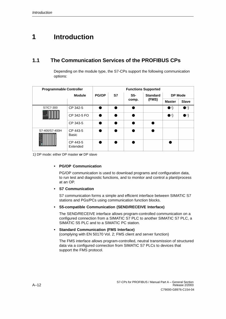
Depending on the module type, the S7-CPs support the following communicationoptions:
Programmable Controller Functions Supported
Module PG/OP S7 S5- Standard(FMS)
DP Modecomp. (FMS)
Master Slave
S7/C7-300 CP 342-5 � � � ��) ��)
CP 342-5 FO � � � ��) ��)
CP 343-5 � � � �
S7-400/S7-400H CP 443-5 Basic
� � � �
CP 443-5 Extended
� � � �
1) DP mode: either DP master or DP slave
� PG/OP Communication
PG/OP communication is used to download programs and configuration data,to run test and diagnostic functions, and to monitor and control a plant/processat an OP.
� S7 Communication
S7 communication forms a simple and efficient interface between SIMATIC S7stations and PGs/PCs using communication function blocks.
� S5-compatible Communication (SEND/RECEIVE Interface)
The SEND/RECEIVE interface allows program-controlled communication on aconfigured connection from a SIMATIC S7 PLC to another SIMATIC S7 PLC, aSIMATIC S5 PLC and to a SIMATIC PC station.
� Standard Communication (FMS Interface)(complying with EN 50170 Vol. 2; FMS client and server function)
The FMS interface allows program-controlled, neutral transmission of structureddata via a configured connection from SIMATIC S7 PLCs to devices thatsupport the FMS protocol.
1
Introduction
A–13S7-CPs for PROFIBUS / Manual Part A – General SectionRelease 2/2003
C79000-G8976-C154-04
� PROFIBUS-DP (complying with EN 50170 Vol. 2; DP master or DP slave)
The distributed peripheral I/Os (DP) allow you to use a large number of analogand digital input/output modules in the immediate vicinity of the process in adistributed configuration.
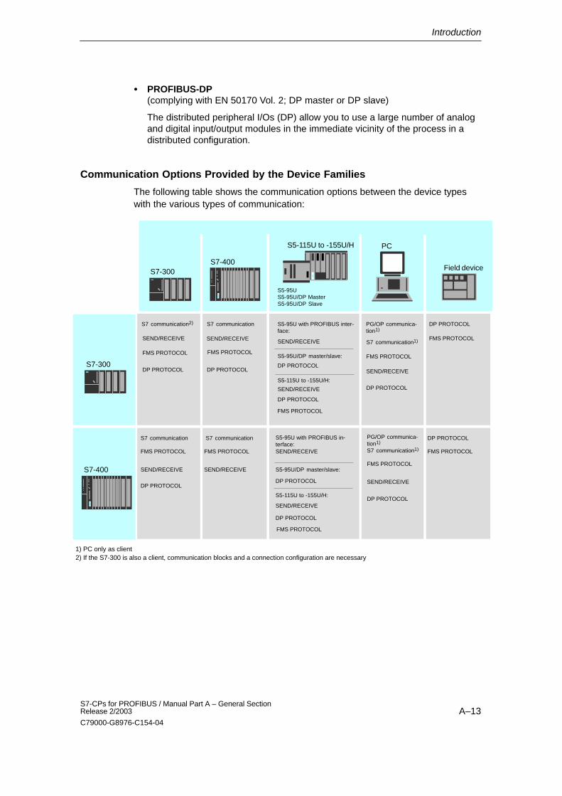
Communication Options Provided by the Device Families
The following table shows the communication options between the device typeswith the various types of communication:
S7-300
S5-95US5-95U/DP MasterS5-95U/DP Slave
S7-400
PC
Field device
S7-300
S7-400
SEND/RECEIVE
SEND/RECEIVE
S7 communication1)
DP PROTOCOL
DP PROTOCOL
S7 communication
SEND/RECEIVE
DP PROTOCOL
SEND/RECEIVE
1) PC only as client
FMS PROTOCOL
DP PROTOCOL
S5-115U to -155U/H
DP PROTOCOL
SEND/RECEIVE
S5-95U with PROFIBUS in-terface:
S5-95U/DP master/slave:
DP PROTOCOL
S5-115U to -155U/H:
SEND/RECEIVE
S7 communication1)
SEND/RECEIVE
DP PROTOCOL
S5-95U with PROFIBUS inter-face:
SEND/RECEIVE
S5-95U/DP master/slave:
DP PROTOCOL
S5-115U to -155U/H:
SEND/RECEIVE
DP PROTOCOL
FMS PROTOCOL
FMS PROTOCOL
FMS PROTOCOL
FMS PROTOCOL FMS PROTOCOL
FMS PROTOCOL
FMS PROTOCOL
FMS PROTOCOL
SEND/RECEIVE
DP PROTOCOL
S7 communication
FMS PROTOCOL
S7 communication
S7 communication2) PG/OP communica-tion1)
PG/OP communica-tion1)
DP PROTOCOL
2) If the S7-300 is also a client, communication blocks and a connection configuration are necessary
Introduction
A–14S7-CPs for PROFIBUS / Manual Part A – General Section
Release 2/2003
C79000-G8976-C154-04
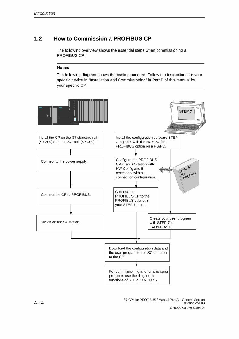
1.2 How to Commission a PROFIBUS CP
The following overview shows the essential steps when commissioning aPROFIBUS CP:
Notice
The following diagram shows the basic procedure. Follow the instructions for yourspecific device in “Installation and Commissioning” in Part B of this manual foryour specific CP.
Install the CP on the S7 standard rail(S7 300) or in the S7 rack (S7-400).
Connect to the power supply.
Connect the CP to PROFIBUS.
Install the configuration software STEP7 together with the NCM S7 forPROFIBUS option on a PG/PC.
Create your user programwith STEP 7 inLAD/FBD/STL.
Configure the PROFIBUSCP in an S7 station withHW Config and ifnecessary with aconnection configuration.
Switch on the S7 station.
Download the configuration data andthe user program to the S7 station orto the CP.
Connect thePROFIBUS CP to thePROFIBUS subnet inyour STEP 7 project.
For commissioning and for analyzingproblems use the diagnosticfunctions of STEP 7 / NCM S7.
Introduction
A–15S7-CPs for PROFIBUS / Manual Part A – General SectionRelease 2/2003
C79000-G8976-C154-04
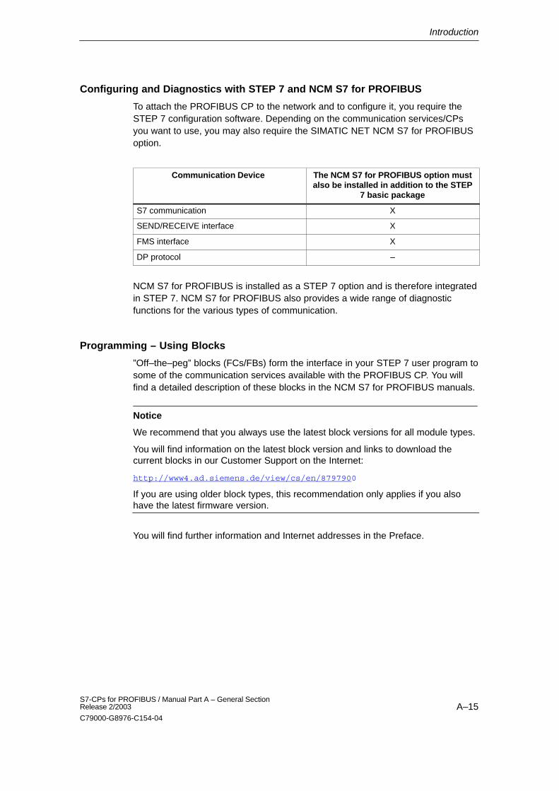
Configuring and Diagnostics with STEP 7 and NCM S7 for PROFIBUS
To attach the PROFIBUS CP to the network and to configure it, you require theSTEP 7 configuration software. Depending on the communication services/CPsyou want to use, you may also require the SIMATIC NET NCM S7 for PROFIBUSoption.
Communication Device The NCM S7 for PROFIBUS option mustalso be installed in addition to the STEP
7 basic package
S7 communication X
SEND/RECEIVE interface X
FMS interface X
DP protocol –
NCM S7 for PROFIBUS is installed as a STEP 7 option and is therefore integratedin STEP 7. NCM S7 for PROFIBUS also provides a wide range of diagnosticfunctions for the various types of communication.
Programming – Using Blocks
”Off–the–peg” blocks (FCs/FBs) form the interface in your STEP 7 user program tosome of the communication services available with the PROFIBUS CP. You willfind a detailed description of these blocks in the NCM S7 for PROFIBUS manuals.
Notice
We recommend that you always use the latest block versions for all module types.
You will find information on the latest block version and links to download thecurrent blocks in our Customer Support on the Internet:
http://www4.ad.siemens.de/view/cs/en/8797900
If you are using older block types, this recommendation only applies if you alsohave the latest firmware version.
You will find further information and Internet addresses in the Preface.
Introduction
A–16S7-CPs for PROFIBUS / Manual Part A – General Section
Release 2/2003
C79000-G8976-C154-04
1.3 Diagnostics During Commissioning and Operation
Diagnostic Options in STEP 7
STEP 7 provides you with a graded concept allowing you to query informationabout the status of your SIMATIC S7 components and functions and to sort outproblems in a variety of different situations. These options cover the following:
� Communication Diagnostics with NCM S7 Diagnostics
The NCM S7 Diagnostics described here provides dynamic information on thestatus of the communication functions of online CPs.
� Hardware Diagnostics and Troubleshooting with STEP 7
Hardware diagnostics provides dynamic information on the status of modulesincluding CPs when the S7 station is online.
You can recognize the existence of diagnostic information for a module by thediagnostics icon in the project window of the SIMATIC Manager. Diagnosticsicons show the status of the corresponding module and also the operatingmode of CPUs.
Detailed diagnostic information is displayed in the “module information” that youcan open by double-clicking a diagnostics icon in the quick view or thediagnostic view.
� HW Config Provides Static Information
Static information means the configured communication properties of an onlineor offline CP and you can display this at any time using the hardwareconfiguration shown by HW Config.
� Online Status in NetPro
In STEP 7, NetPro status information about connections can be displayed whenthe S7 station is online.
Functions of NCM S7 Diagnostics
The diagnostic functions can be grouped as follows:
� General diagnostic and statistical functions
� Type and mode-dependent diagnostic functions
Introduction
A–17S7-CPs for PROFIBUS / Manual Part A – General SectionRelease 2/2003
C79000-G8976-C154-04
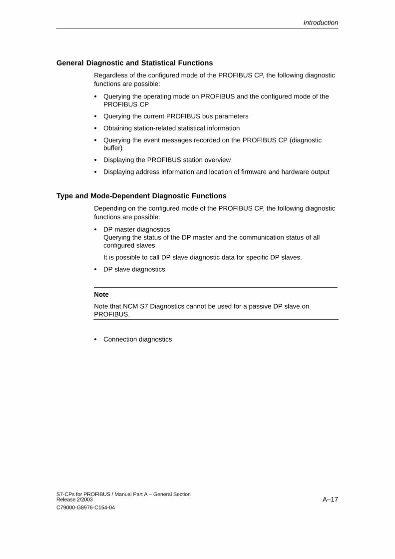
General Diagnostic and Statistical Functions
Regardless of the configured mode of the PROFIBUS CP, the following diagnosticfunctions are possible:
� Querying the operating mode on PROFIBUS and the configured mode of thePROFIBUS CP
� Querying the current PROFIBUS bus parameters
� Obtaining station-related statistical information
� Querying the event messages recorded on the PROFIBUS CP (diagnosticbuffer)
� Displaying the PROFIBUS station overview
� Displaying address information and location of firmware and hardware output
Type and Mode-Dependent Diagnostic Functions
Depending on the configured mode of the PROFIBUS CP, the following diagnosticfunctions are possible:
� DP master diagnosticsQuerying the status of the DP master and the communication status of allconfigured slaves
It is possible to call DP slave diagnostic data for specific DP slaves.
� DP slave diagnostics
Note
Note that NCM S7 Diagnostics cannot be used for a passive DP slave onPROFIBUS.
� Connection diagnostics
Introduction
A–18S7-CPs for PROFIBUS / Manual Part A – General Section
Release 2/2003
C79000-G8976-C154-04
1.4 Loadable Firmware
The PROFIBUS CP supports firmware updates using the Firmware Loader. Afterpower up with the mode selector set to STOP, the CP remains in the ”waiting forfirmware update” status for 10 seconds.
After the firmware update, the rack must be turned off and on again before normaloperation is resumed!
Note
For more detailed information on loading firmware, refer to the NCM S7 forPROFIBUS manual /2/ the README file of the NCM S7 for PROFIBUSconfiguration software.
Structure
A–19S7-CPs for PROFIBUS / Manual Part A – General SectionRelease 2/2003
C79000-G8976-C154-04
Structure
2.1 Communications Processors for S7-300
The modules are designed to match the components of the S7-300/C7-300programmable logic controller and have the following features:
� Compact modules (double or single-width) for simple installation on the S7standard rail
� The operator controls and displays are all located on the front panel
� Direct backplane bus connection via the supplied bus connector
� 9-pin sub-D female connector or duplex sockets for connecting the CP toPROFIBUS
� The modules can be configured via MPI or LAN/PROFIBUS.
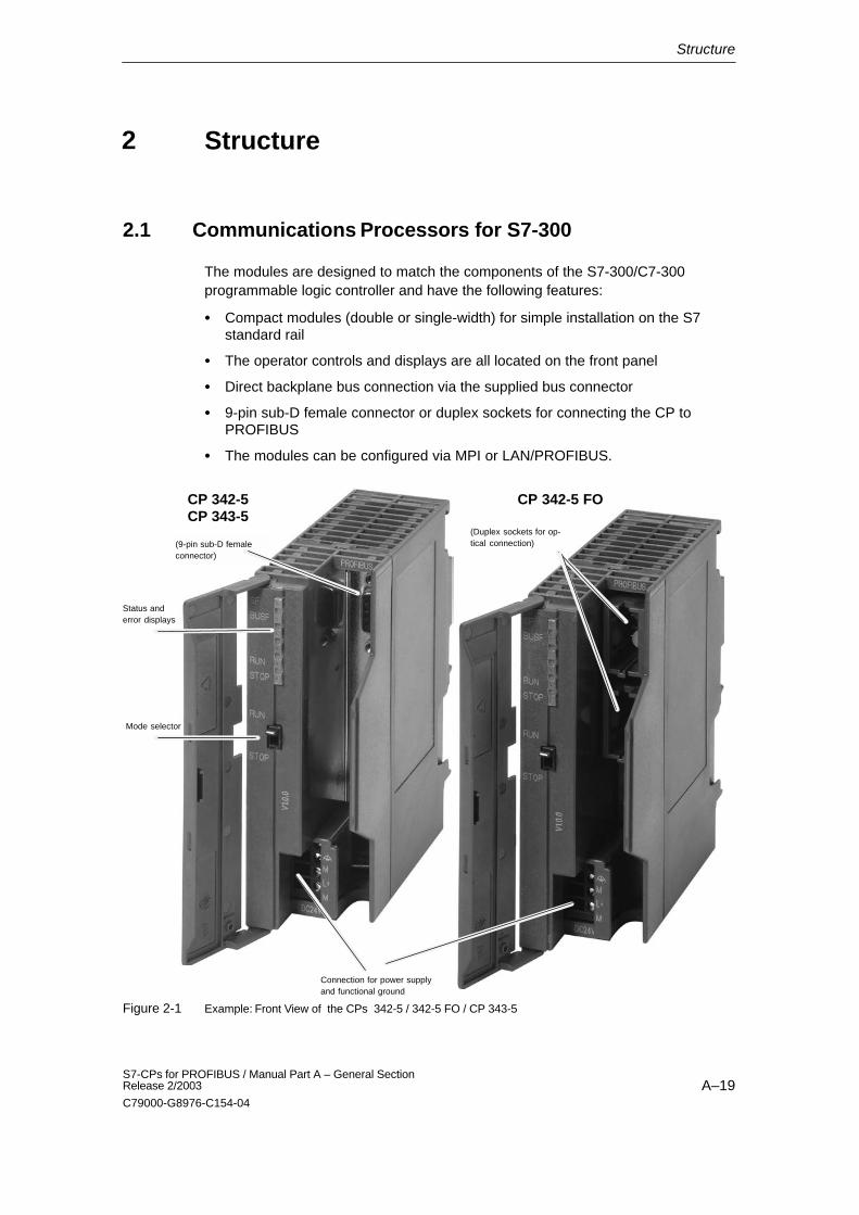
Mode selector
Status and error displays
Connection for power supplyand functional ground
(9-pin sub-D femaleconnector)
CP 342-5CP 343-5
CP 342-5 FO
(Duplex sockets for op-tical connection)
Figure 2-1 Example: Front View of the CPs 342-5 / 342-5 FO / CP 343-5
2
Structure
A–20S7-CPs for PROFIBUS / Manual Part A – General Section
Release 2/2003
C79000-G8976-C154-04
2.2 Communications Processors for S7-400
The modules are designed to match the components of the S7-400 / S7-400H (redundant system) programmable logic controller and have the following features:
� Single-width module for simple installation in the S7-400 / S7-400H (redundantsystem) rack
� The operator controls and displays are all located on the front panel
� Can be used in central or expansion racks
� No fan necessary
� 9-pin sub-D female connector for connecting the CP to PROFIBUS
� The modules can be configured via MPI or LAN/PROFIBUS.
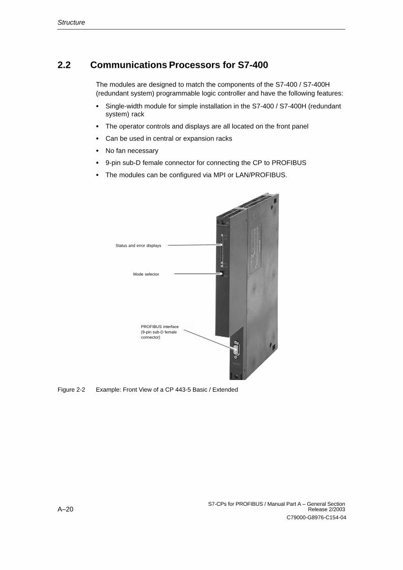
PROFIBUS interface(9-pin sub-D female connector)
Mode selector
Status and error displays
Figure 2-2 Example: Front View of a CP 443-5 Basic / Extended
Attaching to PROFIBUS
A–21S7-CPs for PROFIBUS / Manual Part A – General SectionRelease 2/2003
C79000-G8976-C154-04
Attaching to PROFIBUS
Below, you will see several typical possible attachments.
For further information on attachment options and PROFIBUS structures, refer tothe PROFIBUS network manual /4/. For ordering data and information on furthercomponents, please refer to the IK PI catalog or the CA01 electronic orderingcatalog on CD, and on the Internet at:http://www3.ad.siemens.de/ca01online
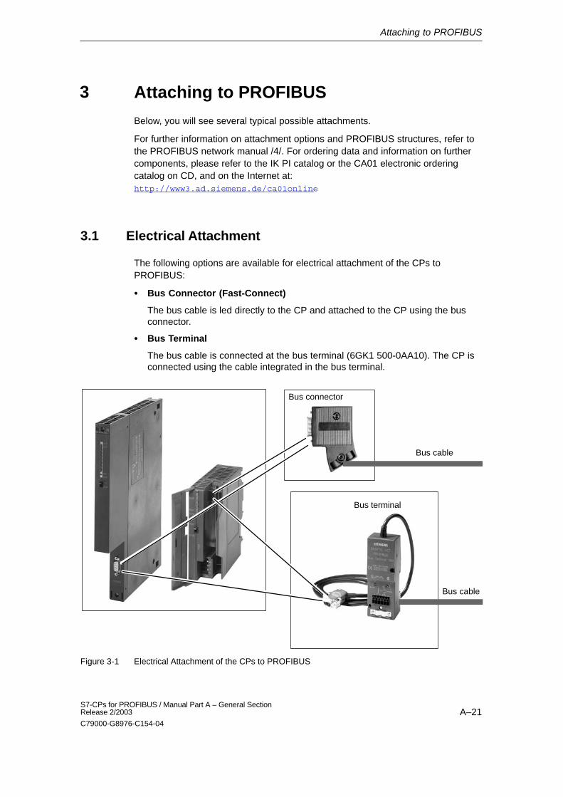
3.1 Electrical Attachment
The following options are available for electrical attachment of the CPs toPROFIBUS:
� Bus Connector (Fast-Connect)
The bus cable is led directly to the CP and attached to the CP using the busconnector.
� Bus Terminal
The bus cable is connected at the bus terminal (6GK1 500-0AA10). The CP isconnected using the cable integrated in the bus terminal.
Bus cable
Bus cable
Bus connector
Bus terminal
Figure 3-1 Electrical Attachment of the CPs to PROFIBUS
3
Attaching to PROFIBUS
A–22S7-CPs for PROFIBUS / Manual Part A – General Section
Release 2/2003
C79000-G8976-C154-04
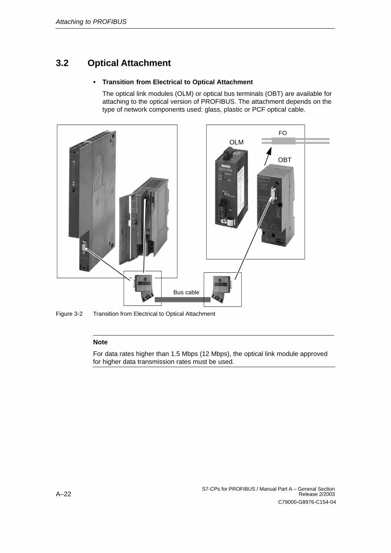
3.2 Optical Attachment
� Transition from Electrical to Optical Attachment
The optical link modules (OLM) or optical bus terminals (OBT) are available forattaching to the optical version of PROFIBUS. The attachment depends on thetype of network components used: glass, plastic or PCF optical cable.
Bus cable
FO
OLM
OBT
Figure 3-2 Transition from Electrical to Optical Attachment
Note
For data rates higher than 1.5 Mbps (12 Mbps), the optical link module approvedfor higher data transmission rates must be used.
Attaching to PROFIBUS
A–23S7-CPs for PROFIBUS / Manual Part A – General SectionRelease 2/2003
C79000-G8976-C154-04
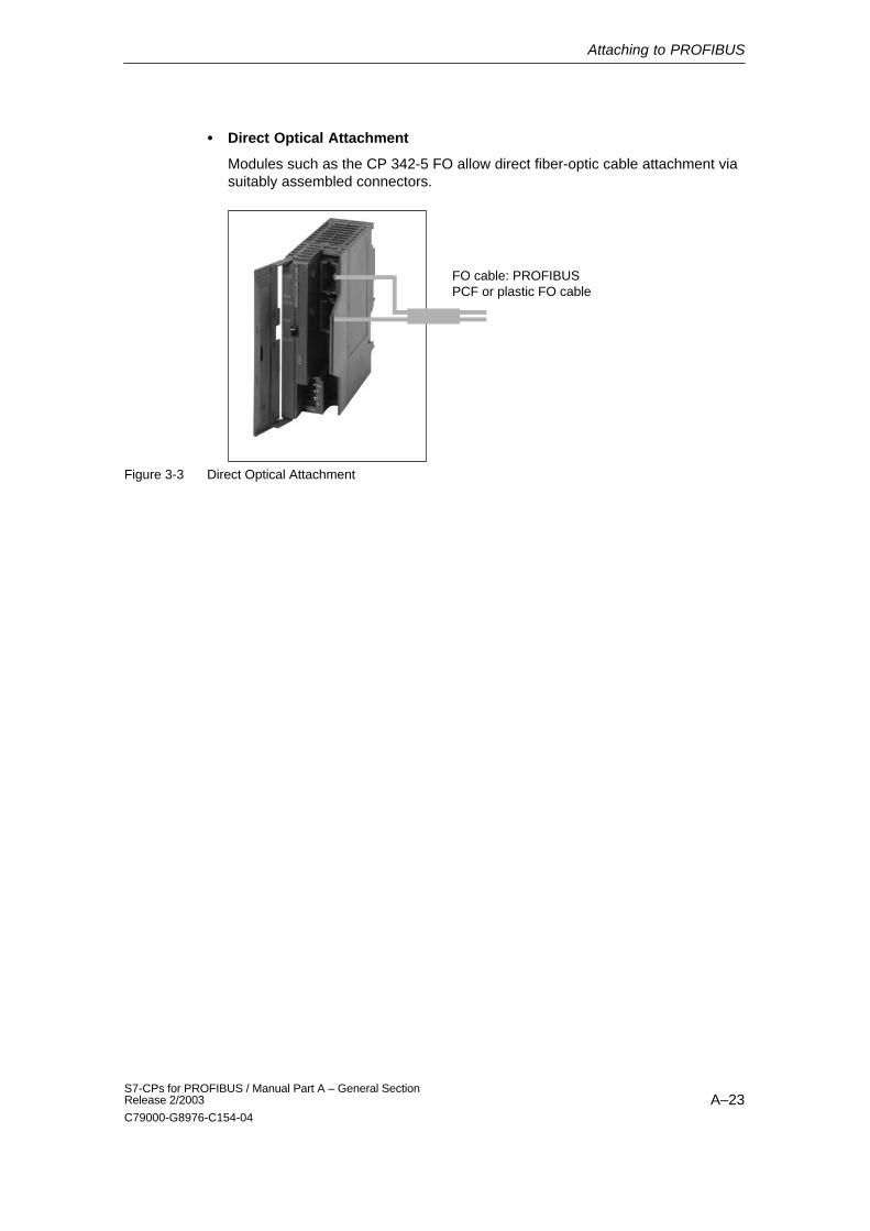
� Direct Optical Attachment
Modules such as the CP 342-5 FO allow direct fiber-optic cable attachment viasuitably assembled connectors.
FO cable: PROFIBUSPCF or plastic FO cable
Figure 3-3 Direct Optical Attachment
Slot Rules and Configurations
A–24S7-CPs for PROFIBUS / Manual Part A – General Section
Release 2/2003
C79000-G8976-C154-04
Slot Rules and Configurations
4.1 SIMATIC S7-300
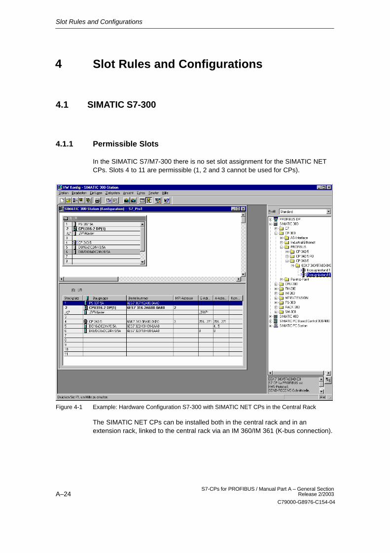
4.1.1 Permissible Slots
In the SIMATIC S7/M7-300 there is no set slot assignment for the SIMATIC NETCPs. Slots 4 to 11 are permissible (1, 2 and 3 cannot be used for CPs).
Figure 4-1 Example: Hardware Configuration S7-300 with SIMATIC NET CPs in the Central Rack
The SIMATIC NET CPs can be installed both in the central rack and in anextension rack, linked to the central rack via an IM 360/IM 361 (K-bus connection).
4
Slot Rules and Configurations
A–25S7-CPs for PROFIBUS / Manual Part A – General SectionRelease 2/2003
C79000-G8976-C154-04
4.1.2 Number of SIMATIC NET CPs
In typical S7–300 configurations, the simultaneous operation of up to 4 CPs of thesame type has been tested successfully. The actual number of SIMATIC NET CPsthat can be operated at the same time is determined by the system (for exampleby the CPU resources).
The connection resources available in the CPU can result in a further limitation.
The load on the CPU resulting from communication jobs may also represent afurther restriction. The following factors should be noted:
� Execution Time of the Blocks:
For communication between the S7-300 CPU and SIMATIC NET CPs, blocks(FCs/FBs) are necessary. How often these blocks are called depends on thenumber of connections or the number of SIMATIC NET CPs. Depending on theamount of data transmitted, every block call extends the time required by theuser program.
� Data conversion:
It may also be necessary for the information to be converted beforetransmission or after reception.
4.1.3 Multicomputing
This functionality is not supported by the SIMATIC S7/C7-300.
4.1.4 CPU Connection Resources and Optimized Utilization
Note that when using older S7-300 CPUs (up to September 1999), a maximum offour S7 type connections for CP communication are supported. Of these fourconnections, one is reserved for a PG and another for an OP (HMI = HumanMachine Interface). The newer CPUs (from 10/99 onwards) support up to 12 S7connections, CPU 318-2DP supports 32 S7 connections.
As a result, the older S7-300 CPUs have only two “free” S7 connections available.These two connections can be used for S7 communication, for PROFIBUS-FMS,or for longer data with Industrial Ethernet.
If you use CPs that support multiplexing of OP connections and S7 communicationwith loadable communication blocks, only one connection resource is occupiedwhen the multiplex channel is used.
Slot Rules and Configurations
A–26S7-CPs for PROFIBUS / Manual Part A – General Section
Release 2/2003
C79000-G8976-C154-04
4.2 SIMATIC S7-400
4.2.1 Permissible Slots
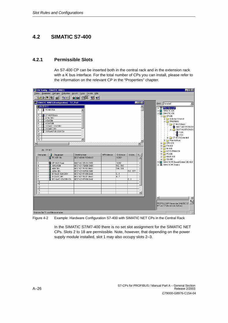
An S7-400 CP can be inserted both in the central rack and in the extension rackwith a K bus interface. For the total number of CPs you can install, please refer tothe information on the relevant CP in the “Properties” chapter.
Figure 4-2 Example: Hardware Configuration S7-400 with SIMATIC NET CPs in the Central Rack
In the SIMATIC S7/M7-400 there is no set slot assignment for the SIMATIC NETCPs. Slots 2 to 18 are permissible. Note, however, that depending on the powersupply module installed, slot 1 may also occupy slots 2–3.
Slot Rules and Configurations
A–27S7-CPs for PROFIBUS / Manual Part A – General SectionRelease 2/2003
C79000-G8976-C154-04
Note
PROFIBUS-DP cannot be used in the extension rack.
Note the following restrictions depending on the services being used:
� SEND/RECEIVE interface
See the CP-specific section of this manual
� S7 communication
The maximum number of modules that can be inserted is limited by the numberof S7 connections of the CPU; see the CP-specific section of this manual.
4.2.2 Number of SIMATIC NET CPs
The number of SIMATIC NET CPs that can be operated simultaneously is limitedby the specific characteristics of the CPU. The exact number can be found in theCP-specific section of this manual.
4.2.3 Multicomputing
This functionality is supported by the SIMATIC S7–400 (see specific sections).
Slot Rules and Configurations
A–28S7-CPs for PROFIBUS / Manual Part A – General Section
Release 2/2003
C79000-G8976-C154-04
4.2.4 Note on the S7-400 CPU: Connection Resources
Note that in the S7-400 CPU, one S7 connection is reserved for a PG and a furtherone for an OP (HMI = Human Machine Interface).
� PG connection via MPI/integrated PROFIBUS-DP interface:
To execute ONLINE functions (for example module diagnostics) from a PG onan S7-400 CP via the MPI/integrated PROFIBUS-DP interface, two connectionresources are necessary on the S7-400 CPU. These two connection resourcesshould be taken into account in the number of S7 connections.
Example: The CPU 412-1 has sixteen free resources for S7 functions available.If a PG is to be used for diagnostics on the S7-400 CP and is connected to theMPI/PROFIBUS-DP interface, two connection resources are required on theS7-400 CPU, so that 14 connection resources remain available.
� PG connection via PROFIBUS or Industrial Ethernet
If the PG is connected to the LAN (PROFIBUS or Industrial Ethernet), in orderto execute PG functions on the S7-400 CPU only one connection resource onthe S7-400 CPU is necessary.
Pinout
A–29S7-CPs for PROFIBUS / Manual Part A – General SectionRelease 2/2003
C79000-G8976-C154-04
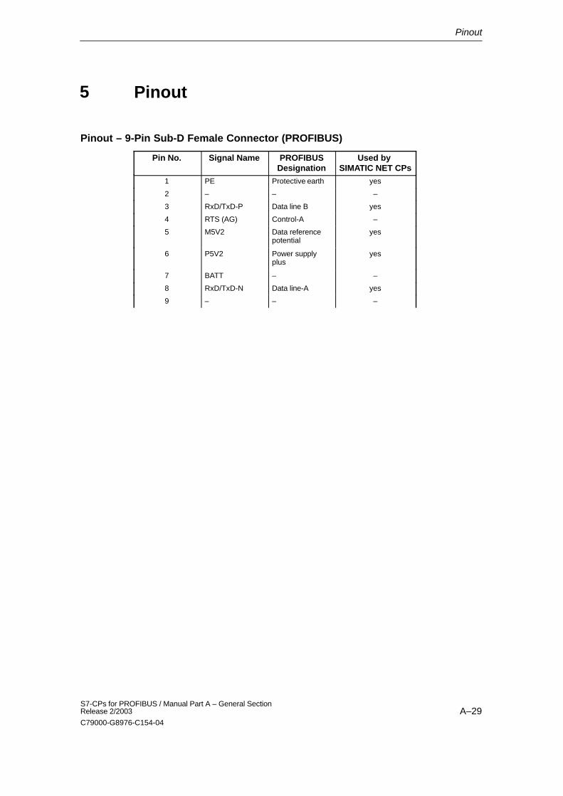
Pinout
Pinout – 9-Pin Sub-D Female Connector (PROFIBUS)
Pin No. Signal Name PROFIBUSDesignation
Used by SIMATIC NET CPs
1 PE Protective earth yes
2 – – –
3 RxD/TxD-P Data line B yes
4 RTS (AG) Control-A –
5 M5V2 Data referencepotential
yes
6 P5V2 Power supplyplus
yes
7 BATT – –
8 RxD/TxD-N Data line-A yes
9 – – –
5

Notes on the CE Mark of SIMATIC NET S7 CPs
A–30S7-CPs for PROFIBUS / Manual Part A – General Section
Release 2/2003
C79000-G8976-C154-04
Notes on the CE Mark of SIMATIC NET S7CPs
Product Name:
� CP 342-5 Order no.: 6GK7 342–5DA02–0XE0
� CP 342-5 FO Order no.: 6GK7 342-5DF00-0XE0
� CP 343-5 Order no.: 6GK7 343–5FA01–0XE0
� CP 443–5 Basic Order no.: 6GK7 443–5FX01–0XE0
� CP 443–5 Extended Order no.: 6GK7 443–5FDX03–0XE0
EU Directive EMC 89/336/EEC
The SIMATIC NET products listed above meet the requirements of the EUdirective 89/336/EEC “Electromagnetic Compatibility”.
The EU conformity certificate is available for the relevant authorities according tothe EU directives and is kept at the following address:
� Siemens AktiengesellschaftBereich A&DIndustrielle Kommunikation SIMATIC NETPostfach 4848D-90327 NurembergGermany
Notice for Australia
The products meet the requirements of the AS/NZS 2064 (class A) standard.
Notice for Canada
This class A digital device meets the requirements of the Canadian ICES-003standard.
AVIS CANADIEN
Cet appareil numérique de la classe A est conforme à la norme NMB-003 duCanada.
Area of Application
The product is designed for use in an industrial environment.
6
Notes on the CE Mark of SIMATIC NET S7 CPs
A–31S7-CPs for PROFIBUS / Manual Part A – General SectionRelease 2/2003
C79000-G8976-C154-04
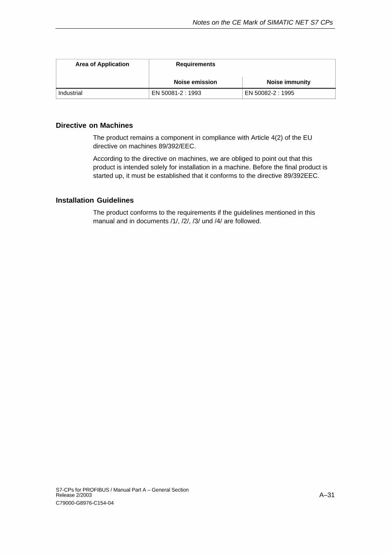
Area of Application Requirements
Noise emission Noise immunity
Industrial EN 50081-2 : 1993 EN 50082-2 : 1995
Directive on Machines
The product remains a component in compliance with Article 4(2) of the EUdirective on machines 89/392/EEC.
According to the directive on machines, we are obliged to point out that thisproduct is intended solely for installation in a machine. Before the final product isstarted up, it must be established that it conforms to the directive 89/392EEC.
Installation Guidelines
The product conforms to the requirements if the guidelines mentioned in thismanual and in documents /1/, /2/, /3/ und /4/ are followed.
References
A–32S7-CPs for PROFIBUS / Manual Part A – General Section
Release 2/2003
C79000-G8976-C154-04
References
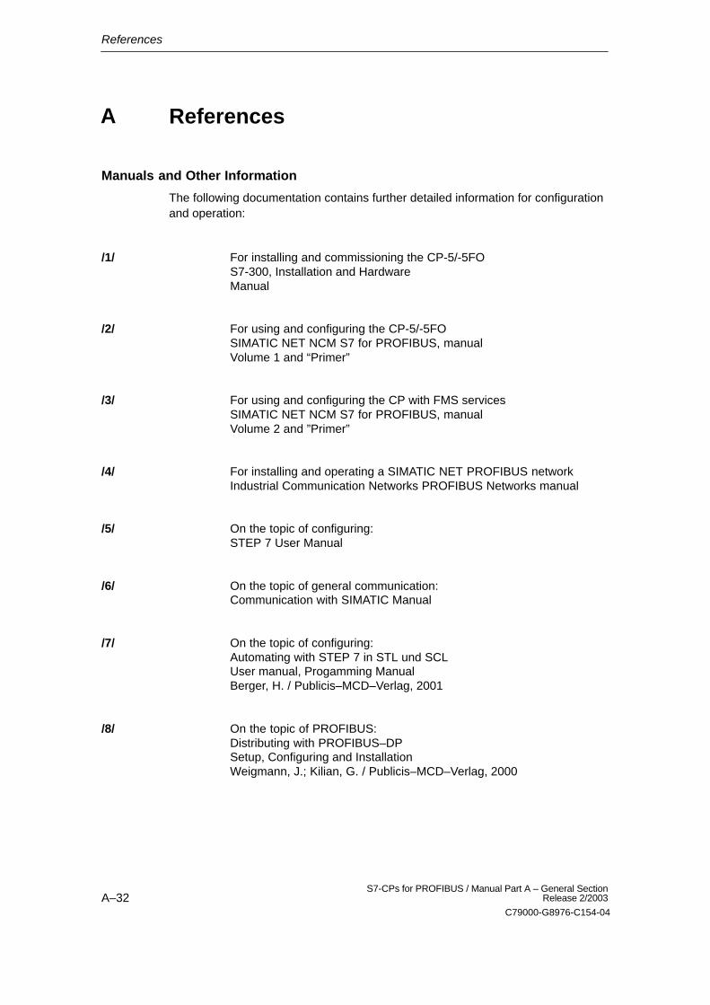
Manuals and Other Information
The following documentation contains further detailed information for configurationand operation:
For installing and commissioning the CP-5/-5FO S7-300, Installation and Hardware Manual
For using and configuring the CP-5/-5FOSIMATIC NET NCM S7 for PROFIBUS, manualVolume 1 and “Primer”
For using and configuring the CP with FMS servicesSIMATIC NET NCM S7 for PROFIBUS, manualVolume 2 and ”Primer”
For installing and operating a SIMATIC NET PROFIBUS networkIndustrial Communication Networks PROFIBUS Networks manual
On the topic of configuring:STEP 7 User Manual
On the topic of general communication:Communication with SIMATIC Manual
On the topic of configuring:Automating with STEP 7 in STL und SCLUser manual, Progamming ManualBerger, H. / Publicis–MCD–Verlag, 2001
On the topic of PROFIBUS:Distributing with PROFIBUS–DPSetup, Configuring and InstallationWeigmann, J.; Kilian, G. / Publicis–MCD–Verlag, 2000
/1/
/2/
/3/
/4/
/5/
/6/
/7/
/8/
A
References
A–33S7-CPs for PROFIBUS / Manual Part A – General SectionRelease 2/2003
C79000-G8976-C154-04
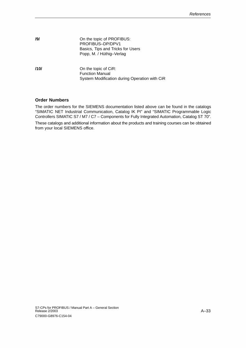
On the topic of PROFIBUS:PROFIBUS–DP/DPV1Basics, Tips and Tricks for UsersPopp, M. / Hüthig–Verlag
On the topic of CiR:Function Manual System Modification during Operation with CiR
Order NumbersThe order numbers for the SIEMENS documentation listed above can be found in the catalogs“SIMATIC NET Industrial Communication, Catalog IK PI” and “SIMATIC Programmable LogicControllers SIMATIC S7 / M7 / C7 – Components for Fully Integrated Automation, Catalog ST 70”.
These catalogs and additional information about the products and training courses can be obtainedfrom your local SIEMENS office.
/9/
/10/
Glossary
A–34S7-CPs for PROFIBUS / Manual Part A – General Section
Release 2/2003
C79000-G8976-C154-04
Glossary
B.1 General Section
Baud rate–> transmission rate
Bus SegmentPart of a –> subnet. Subnets can consist of bus segments and connectivitydevices such as repeaters and bridges. Segments are transparent foraddressing.
ClientA client is a device or, in general terms, an object that requests a service from a–> server.
Configuration DataParameters that determine the modes and functions of a–> CP. They are set anddownloaded using the NCM S7 configuration tool.
CPCommunications processor. Module for communications tasks.
CSMA/CDCSMA/CD (Carrier Sense Multiple Access with Collision Detection)
FCSTEP 7 logic block of the type “function”.
FrameA message from one PROFIBUS/Ethernet station/node to another.
Frame HeaderA frame header consists of an identifier for the –> frame and the source anddestination address.
B
Glossary
A–35S7-CPs for PROFIBUS / Manual Part A – General SectionRelease 2/2003
C79000-G8976-C154-04
Frame TrailerA frame trailer consists of a checksum and the end identifier of the –> frame.
GatewayIntelligent connectivity device that connects local area–> networks of differenttypes at the ISO Layer 7 level.
Industrial EthernetA fieldbus complying with IEEE 802.3 (ISO 8802–2)
NCM S7 for Industrial EthernetConfiguration software for configuration and diagnostic functions on an EthernetCP.
NCM S7 for PROFIBUSConfiguration software for configuration and diagnostic functions on aPROFIBUS CP.
NetworkA network consists of one or more interconnected –> subnets with any numberof –> stations. Several networks can exist side by side.
PG ModeA mode of the PROFIBUS/Ethernet CP in which the SIMATIC S7-CPU isprogrammed, configured or checked via PROFIBUS/Ethernet. This mode is handled by the S7 functions.
Process ImageThe process image is a special memory area in the programmable logiccontroller. At the start of the cyclic program, the signal states of the inputmodules are transferred to the process input image. At the end of the cyclicprogram, the process output image is transferred as a signal state to the outputmodules. As an alternative, asynchronous updates according to the configuration (processimage partition) or according to the programming using SFC 26/27 are possible.
ProtocolA set of rules for transferring data. Using these rules, both the formats of theframes and the data flow are specified.
Glossary
A–36S7-CPs for PROFIBUS / Manual Part A – General Section
Release 2/2003
C79000-G8976-C154-04
SegmentSynonym for –> bus segment.
ServerA server is a device, or in general terms, an object that provides certain services.A service is started at the instigation of a –> client.
ServicesServices provided by a communication protocol.
SIMATIC NETSiemens SIMATIC Network and Communication. Product name for–> networksand network components from Siemens (previously SINEC).
SIMATIC NET for Ind. EthernetSIMATIC NET bus system for industrial applications based on Ethernet(previously SINEC H1)
SINECPrevious product name for–> networks and network components from Siemens.Now: SIMATIC NET
Station A station is identified by a
� MAC address in the Ethernet network.
� PROFIBUS address in the PROFIBUS network.
SubnetA subnet is part of a –> network whose parameters (for example –> PROFIBUS)must be matched. It includes the bus components and all attached stations.Subnets can, for example, be connected together by –> gateways to form anetwork.A –> system consists of several subnets with unique –> subnet numbers. Asubnet consists of several –> stations with unique –> PROFIBUS or MACaddresses (Industrial Ethernet).
SystemThis means all the electrical equipment within a system. A system includes,among other things, programmable logic controllers, devices for operation andmonitoring, bus systems, field devices, actuators, supply lines.
Glossary
A–37S7-CPs for PROFIBUS / Manual Part A – General SectionRelease 2/2003
C79000-G8976-C154-04
Transmission RateAccording to DIN 44302, this is the number of binary decisions transmitted pertime unit. The set or selected transmission rate depends on various conditions,for example the distance across the network. In Ethernet, there is a fixedtransmission rate of 10 Mbps.
Transport InterfaceThe transport interface of a SIMATIC S5 PLC is the access to theconnection-oriented services of the transport layer on the CP. The transportinterface presents itself to the control program in the form of handling blocks(HDBs).
Transport LayerThe transport layer is layer 4 of the ISO/OSI reference model for open systeminterconnection. The purpose of the transport layer is to transfer data reliablyfrom device to device. Transport connections can be used for the transmission.
TSAPTransport Service Access Point
WatchdogMechanism for monitoring operability.
Glossary
A–38S7-CPs for PROFIBUS / Manual Part A – General Section
Release 2/2003
C79000-G8976-C154-04
B.2 PROFIBUS
Base AddressLogical address of a module in S7 systems.
� For PROFIBUSThe PROFIBUS base address is the address starting at which all addressesthat are calculated automatically in the project are assigned.
� For Industrial EthernetThe base MAC address is the address starting at which all addresses that arecalculated automatically in the project are assigned.
Bus ParameterBus parameters control the data transmission on the bus. Each –> station on the–> PROFIBUS network must use bus parameters that match those of otherstations.
CLEAR ModeMode of the DP master. Inputs are read cyclically, outputs remain set to 0.
CommunicationA communication variable is a variable of the programmable controller that isready for communication using FMS services.With S7, communication variables must be configured. After configuration, aneutral structure (in terms of devices) complying with EN 50170 is stored for thevariable.
Control JobGlobal control jobs are control commands for the DP mode such as CLEAR,SYNC, FREEZE, UNFREEZE, ACT, DEACT.
Device DatabaseDevice database files (DDB files) contain DP slave descriptions complying withEN 50170, Vol. 2. The use of device databases data makes it easier to configure–> DP masters and –> DP slaves.
Distributed I/Os (DP)Input and output modules used at a distance (distributed) from the CPU (centralprocessing unit of the controller). The connection between the programmablecontroller and the distributed I/Os is established on the –> PROFIBUS system.The programmable logic controllers do not recognize any difference betweenthese I/Os and local process inputs and outputs.
Glossary
A–39S7-CPs for PROFIBUS / Manual Part A – General SectionRelease 2/2003
C79000-G8976-C154-04
DP I/O ModuleDP slaves have a modular design. A –> DP slave has at least one DP I/Omodule.
DP I/O TypeThe DP I/O type identifies a –> DP I/O module. The following modules arepossible:
� Input module
� Output module
� Input/Output module
� –Empty module
DP MasterA –> station with master functions in –> PROFIBUS DP. Masters come into thefollowing categories:–DP master (class 1) or DP master 1The DP master 1 handles the exchange of user data with the –> DP slavesassigned to it.–DP master (class 2) or DP master 2The DP master 2 provides services such as the following:
� Reading the input/output data
� Diagnostics
� Global control
DP Master SystemA –> DP master and all –> DP slaves with which the DP master exchanges data.
DP ModeThe following operating modes are possible for the connection between the –>DP master and –> DP slaves:
� OFFLINE
� STOP
� CLEAR
� RUN
Each of these modes is characterized by defined actions between the –> DPmaster and –> DP slave.
Glossary
A–40S7-CPs for PROFIBUS / Manual Part A – General Section
Release 2/2003
C79000-G8976-C154-04
DP Module NameName of a –> DP I/O module entered in the DP module list.
DP Module TypeType identifier of a –> DP I/O module in the device master data of a –> DP slavecomplying with EN 50170, Vol 2.
DP SlaveA –> station with slave functions on –> PROFIBUS DP.
DP Slave NameA DP slave name is entered in the DP slave list to identify a –> DP slave in theDP configuration.
DP SubnetPROFIBUS subnet on which only –> distributed I/Os are operated.
FDLFieldbus Data Link. Layer 2 on the –> PROFIBUS.
FDL ConnectionFDL connections allows program/event-controlled communication between aSIMATIC S7 PLC on PROFIBUS and the following:
� SIMATIC S7 PLC with PROFIBUS CP
� SIMATIC S5 PLC with CP 5430/31
� SIMATIC S5-95U with PROFIBUS interface
� PC/PG with CP 5412A1/A2
The transfer of blocks of data on an FDL connection is bi-directional.
FMSField (bus) Message Specification complying with EN 50170, Vol. 2.
FMS ConnectionFMS connections allow program/event-controlled communication betweendevices complying with the FMS standard. Characteristics of the data of aspecific device are neutralized during transmission.
Glossary
A–41S7-CPs for PROFIBUS / Manual Part A – General SectionRelease 2/2003
C79000-G8976-C154-04
FMS Variable–> Communication variable
FREEZE ModeIf the PG is connected to the LAN (PROFIBUS or Industrial Ethernet), in order toexecute PG functions on the S7-400 CPU only one connection resource on theS7-400 CPU is necessary.
Gap Update FactorA free address area (gap) between two active stations/nodes is checkedcyclically to find out whether or not another station/node is requesting to enterthe logical ring.
GetODFMS service for reading the object dictionary (containing, for example, thevariable descriptions) of a –> VFD.
Group IdentifierThe DP slaves can be assigned to one or more groups using a group identifier.The global control frames can be addressed to specific groups of –> DP slavesusing the group identifier.
Highest PROFIBUS AddressA –> bus parameter for –> PROFIBUS. This specifies the highest PROFIBUSaddress of an active –> station on PROFIBUS. Addresses higher than thehighest station address (HSA) are possible for passive stations (possible values:HSA 1 to 126).
MasterActive station on –> PROFIBUS, that can send –> frames unsolicited when it isin possession of the token.
Maximum Station DelayA bus parameter for –> PROFIBUS. The maximum station delay (max. TSDR)specifies the longest interval required by a –> station in the –> subnet betweenreceiving the last bit of an acknowledged frame and sending the first bit of thenext frame. After sending an unacknowledged frame, a sender must wait for themaximum TSDR to expire before sending a further frame.
Glossary
A–42S7-CPs for PROFIBUS / Manual Part A – General Section
Release 2/2003
C79000-G8976-C154-04
Minimum Station DelayA –> bus parameter for –> PROFIBUS. The minimum station delay (min. TSDR)specifies the minimum time that the receiver of a –> frame must wait beforesending the acknowledgment or sending a new frame. The min. TSDR takes intoaccount the longest interval required by a station in the subnet for receiving anacknowledgment after sending a frame.
PollingCyclic processing: In this case, for example, cyclic processing of the ”polling list”on the PROFIBUS CP.
PROFIBUSA fieldbus system complying with EN 50170, Vol. 2 (previously SINEC L2).
PROFIBUS AddressThe PROFIBUS address is a unique identifier for a station/node connected to –>PROFIBUS. The L2 address is transferred in the frame to identify a station/node.
PROFIBUS DPA distributed I/O mode complying with EN 50170, Vol. 2.
PROFIBUS-FMSPROFIBUS Fieldbus Message Specification. Upper sublayer of layer 7 of theISO/OSI reference model on –> PROFIBUS.
PROFIBUS PAPROFIBUS PA is a guideline of the PROFIBUS user organization extending thePROFIBUS EN 50170 by including an intrinsically safe area.
Reorganization Token RingAll the –> masters on –> PROFIBUS form a logical token ring. Within this tokenring, the token is passed on from node to node. If the transmission of the token isincorrect or if a master is removed from the ring, this leads to an error when thetoken is passed on (the token is not accepted by this node) and the node isexcluded from the ring. The number of exclusions is counted in the internal tokenerror counter. If this counter reaches an upper limit value, the logical token ring isthen reorganized.
SCOPE L2Diagnostic product for –> PROFIBUS, with which traffic on the –> network canbe recorded and analyzed.
Glossary
A–43S7-CPs for PROFIBUS / Manual Part A – General SectionRelease 2/2003
C79000-G8976-C154-04
Setup Time A –> bus parameter for –> PROFIBUS. The setup time specifies the minimuminterval on the sender between receiving an acknowledgment and sending a newcall frame.
SIMATIC NET for PROFIBUSSIMATIC NET bus system for industrial applications based on PROFIBUS(previously SINEC L2)
SlaveA passive node on –> PROFIBUS.
Slot TimeA bus parameter for –> PROFIBUS. The slot time (TSL) is the time during whichthe sender of a –> frame waits for the acknowledgment from the receiver beforedetecting a timeout.
Station (PROFIBUS)A station is identified by a –> PROFIBUS address in the –> PROFIBUS network.
SYNC ModeThe SYNC mode in which one, several (group) or all –> DP slaves transfer datato their process outputs at a certain time. The time at which the data istransferred is indicated in the SYNC command (a control command forsynchronization).
Target Rotation TimeA –> bus parameter for –> PROFIBUS. The token represents the right totransmit for a –> station on PROFIBUS. A station compares the actual tokenrotation time it has measured with the target rotation time and, depending on theresult, can then send high or low priority frames.
Token BusNetwork access technique used to assign bus access with several active stations(used on PROFIBUS). The token is passed on from active station to activestation. A complete token rotation takes place between a station sending thetoken and receiving it again.
UNFREEZEJob for resetting the –> FREEZE mode.

Glossary
A–44S7-CPs for PROFIBUS / Manual Part A – General Section
Release 2/2003
C79000-G8976-C154-04
UNSYNCJob for resetting the –> SYNC mode.
Virtual Field Device (VFD)A virtual field device (VFD) is an image of a programmable controller in a neutraldescription. The data and the behavior of the device are described.
Watchdog TimeA monitoring time that can be set on a –> DP slave to detect the failure of the its–> DP master.