Embed Size (px)
Citation preview

Preface, Contents
Product Overview1
Addressing2
ET 200X in the PROFIBUSNetwork
3
ET 200X in the MPI Network4
Installation and Wiring5
Commissioning and Diagnostics6
Functions of the BM 147 CPU7
Cycle and Response Times8
Technical Specifications9
Changing from BM 147 CPU(6ES7 147-1AA01-0XB0) toBM 147-1 CPU or BM 147-2 CPU
10
Position of the BM 147 CPU inthe CPU Range
11
Appendices
Order Numbers A
Glossary, Index
Edition 05/2003EWA-4NEB780602202-04
ET 200X BM 147 CPUBasic Module
Manual
SIMATIC
This manual is part of the documentationpackage with the order number6ES7198-8FA01-8BA0
The following supplement is part of this documentation:
No. Designation Drawing number Edition 1 Product information A5E00385826-02 11/2005

Index-2ET 200X BM 147 CPU Basic Module
EWA-4NEB780602202-04
!Danger
indicates that death, severe personal injury or substantial property damage will result if proper precautionsare not taken.
!Warning
indicates that death, severe personal injury or substantial property damage can result if properprecautions are not taken.
!Caution
indicates that minor personal injury can result if proper precautions are not taken.
Caution
indicates that property damage can result if proper precautions are not taken.
Notice
draws your attention to particularly important information on the product, handling the product, or to aparticular part of the documentation.
Qualified PersonnelOnly qualified personnel should be allowed to install and work on this equipment. Qualified persons aredefined as persons who are authorized to commission, to ground and to tag circuits, equipment, andsystems in accordance with established safety practices and standards.
Correct UsageNote the following:
!Warning
This device and its components may only be used for the applications described in the catalog or thetechnical description, and only in connection with devices or components from other manufacturers whichhave been approved or recommended by Siemens.
This product can only function correctly and safely if it is transported, stored, set up, and installedcorrectly, and operated and maintained as recommended.
TrademarksSIMATIC, SIMATIC HMI and SIMATIC NET are registered trademarks of SIEMENS AG.
Third parties using for their own purposes any other names in this document which refer to trademarksmight infringe upon the rights of the trademark owners.
Safety GuidelinesThis manual contains notices intended to ensure personal safety, as well as to protect the products andconnected equipment against damage. These notices are highlighted by the symbols shown below andgraded according to severity by the following texts:
We have checked the contents of this manual for agreementwith the hardware and software described. Since deviationscannot be precluded entirely, we cannot guarantee fullagreement. However, the data in this manual are reviewedregularly and any necessary corrections included insubsequent editions. Suggestions for improvement arewelcomed.
Disclaim of LiabilityCopyright � Siemens AG 1998-2003 All rights reserved
The reproduction, transmission or use of this document or itscontents is not permitted without express written authority.Offenders will be liable for damages. All rights, including rightscreated by patent grant or registration of a utility model ordesign, are reserved.
Siemens AGBereich Automation and DrivesGeschaeftsgebiet Industrial Automation SystemsPostfach 4848, D- 90327 Nuernberg
Siemens AG 2003Technical data subject to change.
Siemens Aktiengesellschaft EWA-4NEB780602202-04

iiiET 200X BM 147 CPU Basic ModuleEWA-4NEB780602202-04
Preface
Purpose of the manual
This manual complements the ET 200X Distributed I/O Device manual. Itdescribes all the functions of the BM 147 CPU basic module. It does not deal withfunctions that have general applicability to the ET 200X. You will find these in theET 200X Distributed I/O Device manual (see also the Section �Integration in theinformation landscape�).
The information contained in this manual and in the ET 200X Distributed I/OSystem manual will enable you to operate the ET 200X with the BM 147 CPUbasic module as a DP slave on the PROFIBUS-DP or in an MPI network. Themaster functionality of basic module BM 147-2 CPU is also described.
Required level of knowledge
Knowledge of the field of automation engineering is required to understand themanual.
Knowledge on how to use computers or other PC equipment (e.g. programmingdevices) under the Windows 95/98/2000 and NT operating system is also required.You should also be familiar with the STEP 7 basic software. Refer to the�Programming with STEP 7 V5.x� manual.
Scope of validity of the manual
This manual is valid for basic module BM 147-1 CPU with the order number6ES7 147-1AA10-0XB0 and for basic module BM 147-2 CPU with the ordernumber 6ES7 147-2AA00-0XB0, as well as for the components of the ET 200Xdistributed I/O device specified in the ET 200X Distributed I/O Device manual.
Agreement: When features and functions of the basic modules are described inthis handbook that apply to both modules, the designation BM 147 CPU will beused. The full designation is only used when a feature is described that onlyapplies to one of the basic modules.
This manual contains a description of the components that were valid at the timethe manual was published. We reserve the right to enclose a Product Informationbulletin containing up-to-date information about new components and new versionsof components.
Preface
ivET 200X BM 147 CPU Basic Module
EWA-4NEB780602202-04
Changes compared to the previous version
This manual contains the following changes that were made to the previousversion of this manual, Basic Module BM 147 CPU, Edition 03:
� Module name changed to BM 147 CPU
� New order numbers for BM 147 CPU:
� 6ES7 147-1AA10-0XB0 for BM 147-1 CPU
� 6ES7 147-2AA00-0XB0 for BM 147-2 CPU
� Connections using ECOFAST technology
� No mechanical adjustment of the PROFIBUS address on the device
� Coexistent MPI/DP interface
� Additional DP master interface for BM 147-2 CPU
� New memory concept
� Additional communication utilities
� New blocks
� Micro Memory Card (MMC) up to 8 Mbytes
� Data archiving and project storage on MMC
� 32-bit run-time meter
The Instruction list is no longer integrated in the manual. Available commands withthe runtimes and the execution times of the SFCs and SFBs can be found in thedocumentation package in the operations list, S7-300, CPU 31xC, CPU 31x,IM 151-7 CPU, BM 147-1 CPU, BM 147-2 CPU.
Standards, certificates and approvals
The BM 147 CPU basic module is based on the IEC 61784-1:2002 Ed1 CP 3/1standard. It fulfills the requirements and criteria of IEC 61131, Part 2 and therequirements for obtaining the CE marking. For BM 147 CPU, the certifications forcULus have been applied for. You will find detailed information on these standards,certificates and approvals in the ET 200X Distributed I/O Device manual.

Preface
vET 200X BM 147 CPU Basic ModuleEWA-4NEB780602202-04
Position in the information landscape
This manual is a component of the documentation package with the order number6ES7 198-8FA01-8BA0. The package consists of 5 manuals with the followingcontent:
� Installation and wiring
� Commissioning anddiagnostics
� Technical specifications ofdigital and analog modules
� Order numbers for digital andanalog modules
ET 200X Distributed I/ODevice
EM 300 Motor Starter
� Wiring
� Commissioning anddiagnostics
� Technical specifications
� Order numbers
� Addressing
� The ET 200X with theBM 147 CPU in the PROFIBUSnetwork
� The ET 200X with theBM 147 CPU in the MPI network
� Commissioning and diagnostics
� Functions of the BM 147 CPU
� Technical specifications
BM 147 CPU BasicModule
EM 148-FC FrequencyConverter
� Wiring
� Commissioning anddiagnostics
� Functions and technical data
Instruction list S7-300CPU 31xC, CPU 31x,
IM 151-7 CPU, BM 147-1 CPU, BM 147-2 CPU
� The instruction set lists and their executiontimes.
� A list of executable blocks (OBs/SFCs/SFBs)and their execution times
Guide
The manual offers the following useful features that will assist you in rapidly findingthe information you are looking for:
� At the beginning of the manual you will find a comprehensive table of contentsand lists of the figures and tables in the manual.
� The sections of the chapters in the manual contain subheadings that allow youto gain a quick overview of the contents of the section.
� Important technical terminology used in the manual is defined in the Glossary.
� At the end of the manual you will find a comprehensive index enabling rapidaccess to the information you are looking for.

Preface
viET 200X BM 147 CPU Basic Module
EWA-4NEB780602202-04
Special note
In addition to the ET 200X manuals, you will also need the manual for the DPmaster used and the documentation for the configuration and programmingsoftware used (see the list in Appendix A of the ET 200X Distributed I/O Devicemanual).
Note
You will find a detailed list of the contents of the ET 200X manuals in Section 1.2of this manual.
We recommend that you begin by reading this section so as to find out which partsof which manuals are most relevant to you in helping you to do what you want todo.
Recycling and disposal
The components of the BM 147 CPU contain very few harmful substances whichmeans that the unit can be recycled.
Please consult a certified disposal company specializing in electronics waste toensure that your old device is recycled and disposed of in an environment-friendlymanner.
Additional support
Please contact your local Siemens representative if you have any queries aboutthe products described in this manual.http://www.siemens.com/automation/partner
Training center
We offer courses to introduce you to the ET 200 distributed I/O system and theSIMATIC S7 programmable controller. Please contact your local training center orthe central training center in Nuremberg, D-90327 Germany. Telephone: +49 (911) 895-3200Internet: http://www.sitrain.com

Preface
viiET 200X BM 147 CPU Basic ModuleEWA-4NEB780602202-04
A&D Technical Support
Accessible throughout the world at any time of day:
Johnson CityNuremberg
Beijing
Technical Support
Worldwide (Nuremberg)
Technical Support
Loc. time: 0:00 to 24:00 / 365 days
Teleph.: +49 (0) 180 5050-222
Fax: +49 (0) 180 5050-223
E-mail: [email protected]
GMT: +1:00
Europe/Africa (Nuremberg)
Authorization
Loc. time: Mon. - Fri. 8:00 to 17:00
Teleph.: +49 (0) 180 5050-222
Fax: +49 (0) 180 5050-223
E-mail: [email protected]
GMT: +1:00
United States (Johnson City)
Technical Support andAuthorizationLoc. time: Mon. - Fri. 8:00 to 17:00
Teleph.: +1 (0) 423 262 2522
Fax: +1 (0) 423 262 2289
E-mail: [email protected]
GMT: -5:00
Asia / Australia (Beijing)
Technical Support andAuthorizationLoc. time: Mon. - Fri. 8:00 to 17:00
Teleph.: +86 10 64 75 75 75
Fax: +86 10 64 74 74 74
E-mail: [email protected]
GMT: +8:00
Technical support and authorization staff generally speak English and German.

Preface
viiiET 200X BM 147 CPU Basic Module
EWA-4NEB780602202-04
Service & Support on the Internet
In addition to our documentation, we also offer you all of our know-how online onthe Internet.
http://www.siemens.com/automation/service&support
There you will find:
� the newsletter, which constantly supplies you with the latest information on yourproducts
� a search function in Service & Support to help you find the documents you need
� a forum in which users and specialists can exchange their experiencesworldwide
� your local contact partner for Automation & Drives in our contact database
� information on on-site service, repairs and spare parts. You will find a lot moreinformation under �Services�.

ixET 200X BM 147 CPU Basic ModuleEWA-4NEB780602202-04
Contents
1 Product Overview 1-1
1.1 What is the BM 147 CPU basic module? 1-2. . . . . . . . . . . . . . . . . . . . . . . . . . .
1.2 Guide to the ET 200X manuals 1-5. . . . . . . . . . . . . . . . . . . . . . . . . . . . . . . . . . . .
2 Addressing 2-1
2.1 Slot-based addressing 2-2. . . . . . . . . . . . . . . . . . . . . . . . . . . . . . . . . . . . . . . . . . .
2.2 User-oriented addressing of the expansion modules 2-4. . . . . . . . . . . . . . . . . .
2.3 Data interchange with the DP master 2-5. . . . . . . . . . . . . . . . . . . . . . . . . . . . . .
2.4 Accessing the intermediate memory in the BM 147 CPU 2-7. . . . . . . . . . . . . .
3 ET 200X in the PROFIBUS Network 3-1
3.1 ET 200X in the PROFIBUS network 3-2. . . . . . . . . . . . . . . . . . . . . . . . . . . . . . .
3.2 Network components 3-6. . . . . . . . . . . . . . . . . . . . . . . . . . . . . . . . . . . . . . . . . . . .
3.3 PROFIBUS address 3-7. . . . . . . . . . . . . . . . . . . . . . . . . . . . . . . . . . . . . . . . . . . . .
3.4 Functions via the PD/OP 3-8. . . . . . . . . . . . . . . . . . . . . . . . . . . . . . . . . . . . . . . . .
3.5 Direct communication 3-11. . . . . . . . . . . . . . . . . . . . . . . . . . . . . . . . . . . . . . . . . . . .
4 ET 200X in the MPI Network 4-1
4.1 ET 200X in the MPI network 4-2. . . . . . . . . . . . . . . . . . . . . . . . . . . . . . . . . . . . . .
4.2 MPI address 4-4. . . . . . . . . . . . . . . . . . . . . . . . . . . . . . . . . . . . . . . . . . . . . . . . . . . .
5 Installation and Wiring 5-1
6 Commissioning and Diagnostics 6-1
6.1 Configuring the BM 147 CPU 6-2. . . . . . . . . . . . . . . . . . . . . . . . . . . . . . . . . . . . .
6.2 Resetting the memory of the BM 147 CPU 6-5. . . . . . . . . . . . . . . . . . . . . . . . . .
6.3 Commissioning and start-up of the ET 200X 6-8. . . . . . . . . . . . . . . . . . . . . . . . 6.3.1 Starting up the BM 147 CPU as a DP slave 6-8. . . . . . . . . . . . . . . . . . . . . . . . . 6.3.2 Starting up the BM 147-2 CPU as a DP master 6-9. . . . . . . . . . . . . . . . . . . . . . 6.3.3 Start-up 6-12. . . . . . . . . . . . . . . . . . . . . . . . . . . . . . . . . . . . . . . . . . . . . . . . . . . . . . . .
6.4 Diagnostics using LEDs 6-13. . . . . . . . . . . . . . . . . . . . . . . . . . . . . . . . . . . . . . . . . .
6.5 Diagnostics via diagnostic address with STEP 7 6-16. . . . . . . . . . . . . . . . . . . . .
6.6 Slave diagnostics with BM 147 CPU as intelligent slave 6-19. . . . . . . . . . . . . . 6.6.1 Station status 1 to 3 6-20. . . . . . . . . . . . . . . . . . . . . . . . . . . . . . . . . . . . . . . . . . . . . 6.6.2 Master PROFIBUS address 6-22. . . . . . . . . . . . . . . . . . . . . . . . . . . . . . . . . . . . . . 6.6.3 Manufacturer ID 6-22. . . . . . . . . . . . . . . . . . . . . . . . . . . . . . . . . . . . . . . . . . . . . . . . . 6.6.4 Module diagnostics 6-23. . . . . . . . . . . . . . . . . . . . . . . . . . . . . . . . . . . . . . . . . . . . . . 6.6.5 Module status 6-24. . . . . . . . . . . . . . . . . . . . . . . . . . . . . . . . . . . . . . . . . . . . . . . . . . . 6.6.6 Interrupt status 6-25. . . . . . . . . . . . . . . . . . . . . . . . . . . . . . . . . . . . . . . . . . . . . . . . . .
Contents
xET 200X BM 147 CPU Basic Module
EWA-4NEB780602202-04
7 Functions of the BM 147 CPU 7-1
7.1 Data for the PROFIBUS-DP 7-2. . . . . . . . . . . . . . . . . . . . . . . . . . . . . . . . . . . . . .
7.2 The mode selector and LEDs 7-4. . . . . . . . . . . . . . . . . . . . . . . . . . . . . . . . . . . . .
7.3 SIMATIC Micro Memory Card 7-6. . . . . . . . . . . . . . . . . . . . . . . . . . . . . . . . . . . . .
7.4 Memory concept 7-13. . . . . . . . . . . . . . . . . . . . . . . . . . . . . . . . . . . . . . . . . . . . . . . . 7.4.1 Memory areas of the BM 147 CPU 7-13. . . . . . . . . . . . . . . . . . . . . . . . . . . . . . . . 7.4.2 Memory functions 7-16. . . . . . . . . . . . . . . . . . . . . . . . . . . . . . . . . . . . . . . . . . . . . . . 7.4.3 Address areas 7-21. . . . . . . . . . . . . . . . . . . . . . . . . . . . . . . . . . . . . . . . . . . . . . . . . . 7.4.4 Handling data in DBs 7-24. . . . . . . . . . . . . . . . . . . . . . . . . . . . . . . . . . . . . . . . . . . . 7.4.5 Storing/download entire projects on/from Micro Memory Cards 7-26. . . . . . . .
7.5 Interface 7-27. . . . . . . . . . . . . . . . . . . . . . . . . . . . . . . . . . . . . . . . . . . . . . . . . . . . . . .
7.6 Clock 7-29. . . . . . . . . . . . . . . . . . . . . . . . . . . . . . . . . . . . . . . . . . . . . . . . . . . . . . . . . .
7.7 S7 connections 7-30. . . . . . . . . . . . . . . . . . . . . . . . . . . . . . . . . . . . . . . . . . . . . . . . .
7.8 Communication 7-35. . . . . . . . . . . . . . . . . . . . . . . . . . . . . . . . . . . . . . . . . . . . . . . . .
7.9 Routing 7-39. . . . . . . . . . . . . . . . . . . . . . . . . . . . . . . . . . . . . . . . . . . . . . . . . . . . . . . .
7.10 Data consistency 7-42. . . . . . . . . . . . . . . . . . . . . . . . . . . . . . . . . . . . . . . . . . . . . . . .
7.11 Blocks 7-43. . . . . . . . . . . . . . . . . . . . . . . . . . . . . . . . . . . . . . . . . . . . . . . . . . . . . . . . .
7.12 Parameters 7-45. . . . . . . . . . . . . . . . . . . . . . . . . . . . . . . . . . . . . . . . . . . . . . . . . . . . .
8 Cycle and Response Times 8-1
8.1 Cycle time 8-2. . . . . . . . . . . . . . . . . . . . . . . . . . . . . . . . . . . . . . . . . . . . . . . . . . . . . .
8.2 Response time 8-5. . . . . . . . . . . . . . . . . . . . . . . . . . . . . . . . . . . . . . . . . . . . . . . . . .
8.3 Interrupt response time 8-8. . . . . . . . . . . . . . . . . . . . . . . . . . . . . . . . . . . . . . . . . .
8.4 Calculation examples 8-9. . . . . . . . . . . . . . . . . . . . . . . . . . . . . . . . . . . . . . . . . . . . 8.4.1 Calculation examples for the cycle time and response time 8-9. . . . . . . . . . . . 8.4.2 Calculation example for the interrupt response time 8-10. . . . . . . . . . . . . . . . . .
9 Technical Specifications 9-1
9.1 Technical specifications of the BM 147 CPU 9-2. . . . . . . . . . . . . . . . . . . . . . . .
10 Changing from BM 147 CPU (6ES7 147-1AA01-0XB0) to BM 147-1 CPU orBM 147-2 CPU 10-1
11 Position of the BM 147 CPU in the CPU Range 11-1
11.1 Differences to selected S7-300 CPUs 11-2. . . . . . . . . . . . . . . . . . . . . . . . . . . . . .
A Order Numbers A-1
Glossary Glossary-1
Index Index-1
Contents
xiET 200X BM 147 CPU Basic ModuleEWA-4NEB780602202-04
Figures
1-1 View of the ET 200X distributed I/O device with the BM 147 CPU 1-3. . . . . . 1-2 Components and the manuals required for them 1-5. . . . . . . . . . . . . . . . . . . . . 2-1 Principles of data interchange between the DP master and
the ET 200X with the BM 147 CPU 2-1. . . . . . . . . . . . . . . . . . . . . . . . . . . . . . . . 2-2 Structure of the default address area 2-2. . . . . . . . . . . . . . . . . . . . . . . . . . . . . . . 2-3 Slots on the ET 200X 2-2. . . . . . . . . . . . . . . . . . . . . . . . . . . . . . . . . . . . . . . . . . . . 2-4 Example of address assignment to expansion modules 2-3. . . . . . . . . . . . . . . 2-5 Structure of the address area for user-oriented addressing 2-4. . . . . . . . . . . . 2-6 Intermediate memory in the BM 147 CPU 2-5. . . . . . . . . . . . . . . . . . . . . . . . . . . 3-1 Example of a PROFIBUS network 3-2. . . . . . . . . . . . . . . . . . . . . . . . . . . . . . . . . 3-2 Setting the mode of the DP interface at the BM 147 CPU 3-3. . . . . . . . . . . . . 3-3 PD/OP accesses the ET 200X via the DP interface in the DP master 3-5. . . 3-4 The PD directly accesses the ET 200X 3-5. . . . . . . . . . . . . . . . . . . . . . . . . . . . . 3-5 Connecting the DP network 3-6. . . . . . . . . . . . . . . . . . . . . . . . . . . . . . . . . . . . . . . 3-6 Principle behind forcing 3-9. . . . . . . . . . . . . . . . . . . . . . . . . . . . . . . . . . . . . . . . . . 3-7 Direct communication with the BM 147 CPU 3-11. . . . . . . . . . . . . . . . . . . . . . . . 4-1 Example of an MPI network 4-2. . . . . . . . . . . . . . . . . . . . . . . . . . . . . . . . . . . . . . . 5-1 Connecting basic module BM 147-2 CPU to protective ground 5-1. . . . . . . . . 5-2 Interfaces on basic module BM 147 CPU 5-2. . . . . . . . . . . . . . . . . . . . . . . . . . . 5-3 Plugging the connector into the BM 147 CPU 5-3. . . . . . . . . . . . . . . . . . . . . . . 5-4 Plugging in the terminating resistor 5-4. . . . . . . . . . . . . . . . . . . . . . . . . . . . . . . . 6-1 Operating sequence on the mode selector for performing
a general reset 6-6. . . . . . . . . . . . . . . . . . . . . . . . . . . . . . . . . . . . . . . . . . . . . . . . . . 6-2 Position of LEDs on basic module BM 147 CPU 6-13. . . . . . . . . . . . . . . . . . . . . 6-3 Diagnostic addresses for the DP master and ET 200X 6-16. . . . . . . . . . . . . . . . 6-4 Format of the slave diagnostic data 6-19. . . . . . . . . . . . . . . . . . . . . . . . . . . . . . . . 6-5 Structure of the module diagnosis for the BM 147 CPU 6-23. . . . . . . . . . . . . . . 6-6 Structure of the module status 6-24. . . . . . . . . . . . . . . . . . . . . . . . . . . . . . . . . . . . 6-7 Structure of the interrupt status 6-25. . . . . . . . . . . . . . . . . . . . . . . . . . . . . . . . . . . . 6-8 Byte y+4 to y+7 for the diagnostic interrupt
(changed operating status of the intelligent slave) 6-26. . . . . . . . . . . . . . . . . . . . 6-9 Byte y+4 to y+7 for diagnostic interrupt (SFB 75) 6-27. . . . . . . . . . . . . . . . . . . . 7-1 Mode selector 7-4. . . . . . . . . . . . . . . . . . . . . . . . . . . . . . . . . . . . . . . . . . . . . . . . . . 7-2 Position of the memory card slot for the MMC on the BM 147 CPU 7-10. . . . . 7-3 Memory areas of the BM 147 CPU 7-13. . . . . . . . . . . . . . . . . . . . . . . . . . . . . . . . 7-4 Load and working memory 7-16. . . . . . . . . . . . . . . . . . . . . . . . . . . . . . . . . . . . . . . . 7-5 Processing steps within a cycle 7-22. . . . . . . . . . . . . . . . . . . . . . . . . . . . . . . . . . . 7-6 Handling recipe data 7-24. . . . . . . . . . . . . . . . . . . . . . . . . . . . . . . . . . . . . . . . . . . . . 7-7 Handling measured value archives 7-25. . . . . . . . . . . . . . . . . . . . . . . . . . . . . . . . . 7-8 Routing gateway 7-40. . . . . . . . . . . . . . . . . . . . . . . . . . . . . . . . . . . . . . . . . . . . . . . . 7-9 Routing � TeleService application example 7-41. . . . . . . . . . . . . . . . . . . . . . . . . . 8-1 Component parts of the cycle time 8-2. . . . . . . . . . . . . . . . . . . . . . . . . . . . . . . . . 8-2 Shortest response time 8-6. . . . . . . . . . . . . . . . . . . . . . . . . . . . . . . . . . . . . . . . . . 8-3 Longest response time 8-7. . . . . . . . . . . . . . . . . . . . . . . . . . . . . . . . . . . . . . . . . . . 9-1 Block diagram BM 147 CPU 9-4. . . . . . . . . . . . . . . . . . . . . . . . . . . . . . . . . . . . . . 9-2 Dimensioned drawing of basic module BM 147 CPU
(BM 147-2 CPU is shown) 9-5. . . . . . . . . . . . . . . . . . . . . . . . . . . . . . . . . . . . . . . .

Contents
xiiET 200X BM 147 CPU Basic Module
EWA-4NEB780602202-04
Tables
1-1 Interface concept of the BM 147 CPU 1-3. . . . . . . . . . . . . . . . . . . . . . . . . . . . . . 1-2 Topics of the manuals in the ET 200X manual package 1-6. . . . . . . . . . . . . . . 2-1 Addresses of the ET 200X expansion modules 2-3. . . . . . . . . . . . . . . . . . . . . . 2-2 Accessing the address areas 2-7. . . . . . . . . . . . . . . . . . . . . . . . . . . . . . . . . . . . . 2-3 Addressing interface in STEP 7 (extract) 2-8. . . . . . . . . . . . . . . . . . . . . . . . . . . 3-1 Behavior of the BM 147 CPU depending on the DP interface setting 3-4. . . . 6-1 Configuration options 6-2. . . . . . . . . . . . . . . . . . . . . . . . . . . . . . . . . . . . . . . . . . . . 6-2 Ways to reset the memory 6-5. . . . . . . . . . . . . . . . . . . . . . . . . . . . . . . . . . . . . . . . 6-3 Internal CPU events at memory resetting 6-6. . . . . . . . . . . . . . . . . . . . . . . . . . . 6-4 Event recognition of the BM 147-2 CPU as a DP master 6-10. . . . . . . . . . . . . . 6-5 LED display for PROFIBUS-DP (BM 147 CPU is a slave) 6-14. . . . . . . . . . . . . 6-6 LED display for PROFIBUS-DP (BM 147-2 CPU is a master) 6-15. . . . . . . . . . 6-7 Responses to operating mode changes and interruptions in user
data transfer in the DP master and the ET 200X with the BM 147 CPU 6-17. 6-8 Evaluation of RUN/STOP Transitions in the DP Master/ET 200X 6-18. . . . . . . 6-9 Structure of station status 1 (byte 0) 6-20. . . . . . . . . . . . . . . . . . . . . . . . . . . . . . . 6-10 Structure of station status 2 (byte 1) 6-21. . . . . . . . . . . . . . . . . . . . . . . . . . . . . . . 6-11 Structure of station status 3 (byte 2) 6-21. . . . . . . . . . . . . . . . . . . . . . . . . . . . . . . 6-12 Structure of the master PROFIBUS address (byte 3) 6-22. . . . . . . . . . . . . . . . . 6-13 Structure of the manufacturer identification (bytes 4 and 5) 6-22. . . . . . . . . . . . 7-1 Positions of the mode selector 7-4. . . . . . . . . . . . . . . . . . . . . . . . . . . . . . . . . . . . 7-2 LEDs for CPU functionality 7-5. . . . . . . . . . . . . . . . . . . . . . . . . . . . . . . . . . . . . . . 7-3 Available MMCs 7-8. . . . . . . . . . . . . . . . . . . . . . . . . . . . . . . . . . . . . . . . . . . . . . . . . 7-4 Firmware update with MMC 7-11. . . . . . . . . . . . . . . . . . . . . . . . . . . . . . . . . . . . . . . 7-5 Backing up the operating system 7-12. . . . . . . . . . . . . . . . . . . . . . . . . . . . . . . . . . 7-6 Retentive behavior of the memory objects 7-15. . . . . . . . . . . . . . . . . . . . . . . . . . 7-7 Retentive behavior of the DBs in BM 147 CPU 7-15. . . . . . . . . . . . . . . . . . . . . . 7-8 Address areas of the system memory 7-21. . . . . . . . . . . . . . . . . . . . . . . . . . . . . . 7-9 Connectable devices 7-28. . . . . . . . . . . . . . . . . . . . . . . . . . . . . . . . . . . . . . . . . . . . . 7-10 Features of the clock 7-29. . . . . . . . . . . . . . . . . . . . . . . . . . . . . . . . . . . . . . . . . . . . 7-11 Distribution of the S7 connections 7-33. . . . . . . . . . . . . . . . . . . . . . . . . . . . . . . . . 7-12 Availability of the S7 connections 7-34. . . . . . . . . . . . . . . . . . . . . . . . . . . . . . . . . . 7-13 Communication utilities of the BM 147 CPU 7-35. . . . . . . . . . . . . . . . . . . . . . . . . 7-14 GD resources of the BM 147 CPU 7-38. . . . . . . . . . . . . . . . . . . . . . . . . . . . . . . . . 7-15 Overview of the Blocks 7-43. . . . . . . . . . . . . . . . . . . . . . . . . . . . . . . . . . . . . . . . . . . 7-16 Parameter blocks, settable parameters and their ranges for
the BM 147 CPU 7-45. . . . . . . . . . . . . . . . . . . . . . . . . . . . . . . . . . . . . . . . . . . . . . . . 8-1 Operating system processing time in the scan cycle checkpoint 8-3. . . . . . . . 8-2 Process image updating 8-3. . . . . . . . . . . . . . . . . . . . . . . . . . . . . . . . . . . . . . . . . . 8-3 Extending the cycle by nesting interrupts 8-4. . . . . . . . . . . . . . . . . . . . . . . . . . . 8-4 Interrupt response times of the BM 147 CPU (without communication) 8-8. . 9-1 Pin assignment of basic module BM 147 CPU 9-3. . . . . . . . . . . . . . . . . . . . . . . 11-1 Differences to selected S7-300 CPUs 11-2. . . . . . . . . . . . . . . . . . . . . . . . . . . . . . A-1 BM 147 CPU basic modules � order numbers A-1. . . . . . . . . . . . . . . . . . . . . . . A-2 Micro Memory Cards � order numbers A-1. . . . . . . . . . . . . . . . . . . . . . . . . . . . . A-3 Accessories � order numbers A-2. . . . . . . . . . . . . . . . . . . . . . . . . . . . . . . . . . . . .

1-1ET 200X BM 147 CPU Basic ModuleEWA-4NEB780602202-04
Product Overview
In this chapter
The product overview provides information about
� The role of the BM 147 CPU basic module within the ET 200X distributed I/Odevice
� Which manuals in the ET 200X manual package contain what information.
In this chapter
InSection
Contents Page
1.1 What is the BM 147 CPU basic module? 1-2
1.2 Guide to the ET 200X manuals 1-5
1

Product Overview
1-2ET 200X BM 147 CPU Basic Module
EWA-4NEB780602202-04
1.1 What is the BM 147 CPU basic module?
What is the BM 147 CPU basic module?
The BM 147 CPU is a component of the ET 200X distributed I/0 device designed inthe degrees of protection IP 65, IP 66 and IP 67. Unlike all other basic modules,the BM 147 CPU features integrated PLC functionality for pre-processingpurposes. It enables you to decentralize control tasks.
An ET 200X with a BM 147 CPU can therefore exercise full and, if necessary,independent control over a process-related functional unit and can be used as astand-alone CPU. The use of the BM 147 CPU leads to further modularization andstandardization of technological functional units and simple, clear machineconcepts.
How is the BM 147 CPU integrated in the ET 200X?
The BM 147 CPU basic module is integrated in the ET 200X in the same way asany other basic module. In other words, its configuration concept, installation andexpansion capability are the same.

Product Overview
1-3ET 200X BM 147 CPU Basic ModuleEWA-4NEB780602202-04
View
The figure below shows a sample configuration of an ET 200X with aBM 147 CPU.
X03 MPI
x2
x3 x4
x1 x2
x3
x1
X04 X01 X02
SFBF-MBF-S
ON
24 VDCFRCE
RUNSTOP
BM 147-2 CPUbasic module
Expansion modules
ECOFAST connector for PROFIBUS-DP, non-switched supply voltage (1L+)and switched load voltage (2L+)(master side)
ECOFAST connector for PROFIBUS-DP, non-swit-ched supply voltage (1L+)and switched load voltage (2L+)(slave side)
DP-M DP-IN DP-OUT
Figure 1-1 View of the ET 200X distributed I/O device with the BM 147 CPU
Interface
The BM 147 CPU has the following interfaces:
Table 1-1 Interface concept of the BM 147 CPU
Description Functionality Plug-inconnection
Remarks on functionality
X01(DP-IN)
MPI/DPslave interface (feed)
ECOFAST
Coexistent MPI/DPX02
(DP-OUT)MPI/DPslave interface (looped through)
ECOFASTCoexistent MPI/DPinterface one logicalinterface
X03(MPI)
MPI/DPPD interface
9-pinSub-D socket
interface
X04 1)(DP-M)
DPmaster interface
ECOFAST Additional DP master interface
1) Only featured in BM 147-2 CPU

Product Overview
1-4ET 200X BM 147 CPU Basic Module
EWA-4NEB780602202-04
Features of the BM 147 CPU in contrast to other basic modules
The BM 147 CPU basic module has the following special features:
� The basic module has PLC functionality (integrated CPU component with48 kByte working memory).
� The basic module can only be operated with fitted load memory (MMC).
� The basic module does not have integrated inputs and outputs, but, like anyother basic module, up to 7 expansion modules can be added to it from theET 200X range.
� The basic module has an operating mode switch with positions for RUN, STOPand MRES.
� There are 8 LEDs on the front of the interface module to indicate the following:
� ET 200X faults (SF)
� Bus faults (BF-S and BF-M) (BF-M only in BM 147-2 CPU),
� Non-switched supply voltage for electronics/sensors (1L+) (ON),
� Switched load voltage (2L+) (24 VDC),
� Force requests (FRCE)
� Operating mode of the BM 147 CPU (RUN and STOP)
� The BM 147-2 CPU basic module also contains an additional interface with DP master functionality.
How is the ET 200X configured with the BM 147 CPU?
To configure the ET 200X with the BM 147 CPU (configuration andparameterization), you will require the STEP 7 configuration software as of versionV 5.2 + Service Pack 1. How to configure the ET 200X with the BM 147 CPU isdescribed in Section 6.1 of this manual.
How is the BM 147 CPU programmed?
To program the BM 147 CPU, you will require the STEP 7 configuration softwareas of version V 5.2 + Service Pack 1. In the Instruction list, you will find theSTEP 7 instruction set for programming the BM 147 CPU.
Product Overview
1-5ET 200X BM 147 CPU Basic ModuleEWA-4NEB780602202-04
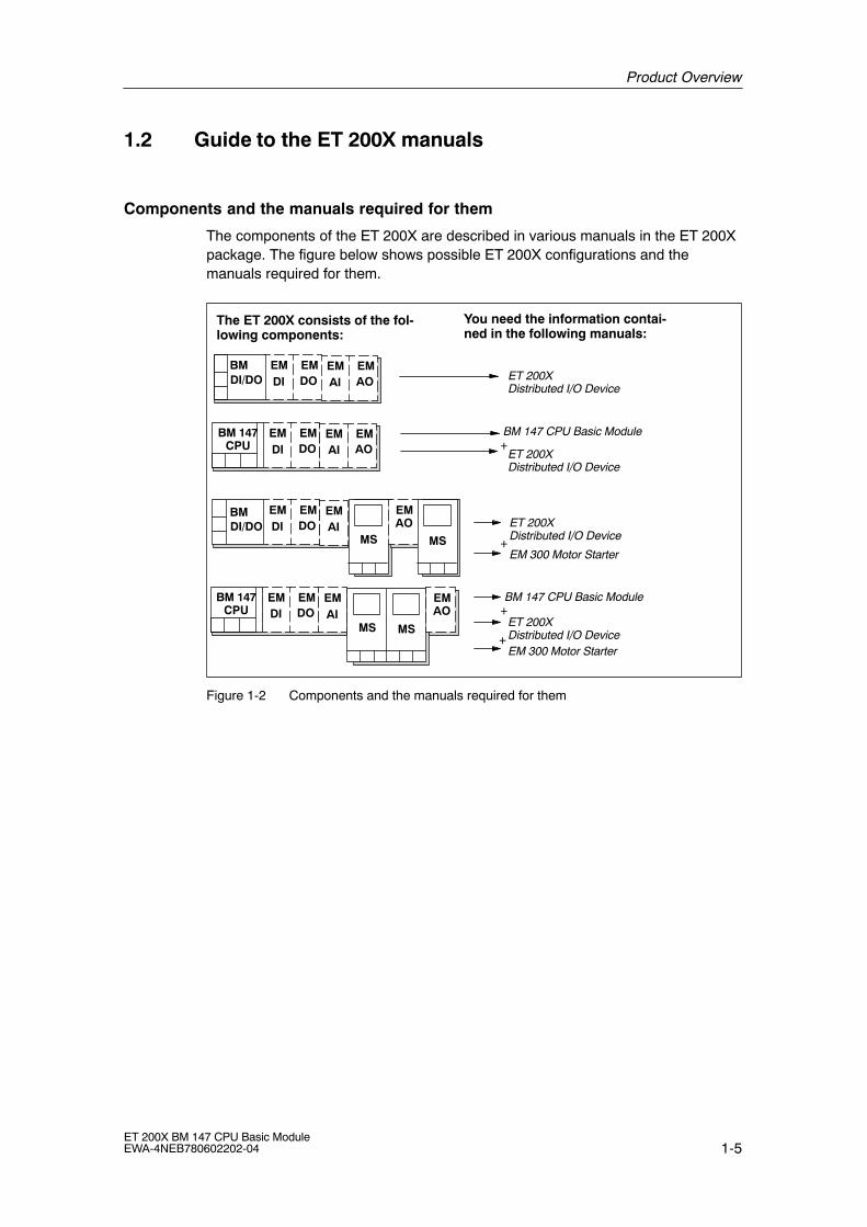
1.2 Guide to the ET 200X manuals
Components and the manuals required for them
The components of the ET 200X are described in various manuals in the ET 200Xpackage. The figure below shows possible ET 200X configurations and themanuals required for them.
EM EMDI DO
The ET 200X consists of the fol-lowing components:
You need the information contai-ned in the following manuals:
EM EMAI AO
EM EMDI DO
EM EMAI AO
EM EMDI DO
BMDI/DO
EMAI
EM EMDI DO
EMAI
MS MS
BM 147 CPU Basic Module
EM 300 Motor Starter
BM 147 CPU Basic Module
ET 200XDistributed I/O DeviceEM 300 Motor Starter
ET 200XDistributed I/O Device
ET 200XDistributed I/O Device
ET 200XDistributed I/O Device
+
+
+
+
MS
EMAO
EMAO
MS
BM 147CPU
BMDI/DO
BM 147CPU
Figure 1-2 Components and the manuals required for them
Product Overview
1-6ET 200X BM 147 CPU Basic Module
EWA-4NEB780602202-04
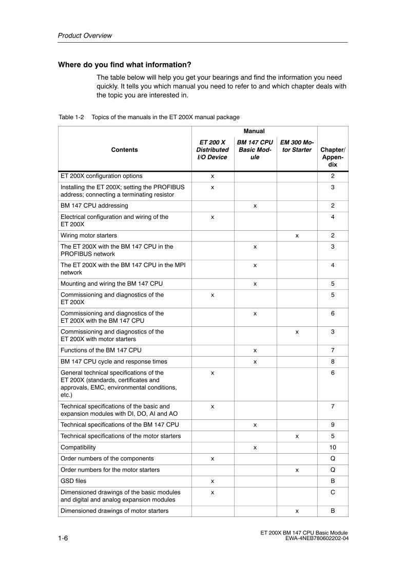
Where do you find what information?
The table below will help you get your bearings and find the information you needquickly. It tells you which manual you need to refer to and which chapter deals withthe topic you are interested in.
Table 1-2 Topics of the manuals in the ET 200X manual package
Manual
ContentsET 200 X
DistributedI/O Device
BM 147 CPUBasic Mod-
ule
EM 300 Mo-tor Starter Chapter/
Appen-dix
ET 200X configuration options x 2
Installing the ET 200X; setting the PROFIBUSaddress; connecting a terminating resistor
x 3
BM 147 CPU addressing x 2
Electrical configuration and wiring of theET 200X
x 4
Wiring motor starters x 2
The ET 200X with the BM 147 CPU in thePROFIBUS network
x 3
The ET 200X with the BM 147 CPU in the MPInetwork
x 4
Mounting and wiring the BM 147 CPU x 5
Commissioning and diagnostics of theET 200X
x 5
Commissioning and diagnostics of theET 200X with the BM 147 CPU
x 6
Commissioning and diagnostics of theET 200X with motor starters
x 3
Functions of the BM 147 CPU x 7
BM 147 CPU cycle and response times x 8
General technical specifications of theET 200X (standards, certificates andapprovals, EMC, environmental conditions,etc.)
x 6
Technical specifications of the basic andexpansion modules with DI, DO, AI and AO
x 7
Technical specifications of the BM 147 CPU x 9
Technical specifications of the motor starters x 5
Compatibility x 10
Order numbers of the components x Q
Order numbers for the motor starters x Q
GSD files x B
Dimensioned drawings of the basic modulesand digital and analog expansion modules
x C
Dimensioned drawings of motor starters x B

Product Overview
1-7ET 200X BM 147 CPU Basic ModuleEWA-4NEB780602202-04
Table 1-2 Topics of the manuals in the ET 200X manual package
Manual
Contents Chapter/Appen-
dix
EM 300 Mo-tor Starter
BM 147 CPUBasic Mod-
ule
ET 200 XDistributedI/O Device
Configuration assignment frame for motorstarters
x C
Position of the BM 147 CPU in the CPU range x 11
Glossary x x Glossary
The frame for configuration and parameter assignment for the BM 147 CPU can be found on the Internet athttp://www.ad.siemens.de/simatic-cs

Product Overview
1-8ET 200X BM 147 CPU Basic Module
EWA-4NEB780602202-04

2-1ET 200X BM 147 CPU Basic ModuleEWA-4NEB780602202-04
Addressing
Principles of data interchange between the DP master and the ET 200X
The figure below illustrates both mechanisms of data interchange for whichaddresses are required in the ET 200X. In this chapter you will find all theinformation you need on the addressing of the ET 200X with the BM 147 CPU.
ET 200XDP master
EMBM 147 CPU
� Data interchange between the DP master and the ET 200X via an intermediate memory in the BM 147 CPU
�
� Data interchange between the BM 147 CPU and expansion modules
�
Figure 2-1 Principles of data interchange between the DP master and the ET 200X with theBM 147 CPU
In this chapter
In Section Contents Page
2.1 Slot-based addressing 2-2
2.2 User-oriented addressing of the expansion modules 2-4
2.3 Data interchange with the DP master 2-5
2.4 Accessing the intermediate memory in the BM 147 CPU 2-7
2

Addressing
2-2ET 200X BM 147 CPU Basic Module
EWA-4NEB780602202-04
2.1 Slot-based addressing
Slot-oriented address allocation
In slot-based addressing (default addressing), each of a module�s slot numbers isassigned an address area in the BM 147 CPU.
Depending on the type of the expansion module, the addresses are digital oranalog (see Table 2-1). The address allocation is not fixed and can be changed,but there is a default address area.
0
127
128
255
256
367
368
1023
4 bytes per digital module, pneumatic module, valve island, EM148-FC, motor starter
16 bytes per analog module
Figure 2-2 Structure of the default address area
Slot assignment
The figure below shows an ET 200X configuration with 7 expansion modules(maximum configuration) and the slot assignment.
Slot numbers
BM EM EMEMEM
ET 200XEMEMEM
4 5 6 7 8 9 101 to 3
Figure 2-3 Slots on the ET 200X
Slot rules
When assembling an ET 200X with extension modules and pneumatic interfacemodules, follow the rules in the ET 200X Distributed I/O Device manual, Chap. 2.8.
Addressing
2-3ET 200X BM 147 CPU Basic ModuleEWA-4NEB780602202-04
Address assignment
For each of the expansion modules, of which there can be up to seven, 4 bytes arereserved for digital I/O devices and 16 bytes for analog I/O devices, depending onthe slot, in the address areas of the BM 147 CPU.
The table below indicates the fixed address assignment for analog and digitalmodules per slot. The address areas of the expansion modules are �visible� only toa BM 147 CPU in the ET 200X, not to the associated DP master. The DP masterhas no access to the expansion modules.
Table 2-1 Addresses of the ET 200X expansion modules
Reserveddd
Slot numberaddress area
1 2 3 4 5 6 7 8 9 10
Digital modules Basicd l
0 to 3 4 to 7 8 to 11 12 to 15 16 to 19 20 to 23 24 to 27
Analogmodules
module256 to
271272 to
287 288 to
303304 to
319320 to
335336 to
351352 to
367
The unassigned addresses in the range 28 to 127 are in the process image indefault addressing and can be used any way you choose in the user program. If 4bits in a byte are already used, the remaining 4 bits cannot be used.
You can use the bytes in the address areas that are not used by modules in anyway you choose in your user program. In the configuration in Figure 2-4, forexample, bytes 1, 2 and 3 can be used as you choose.
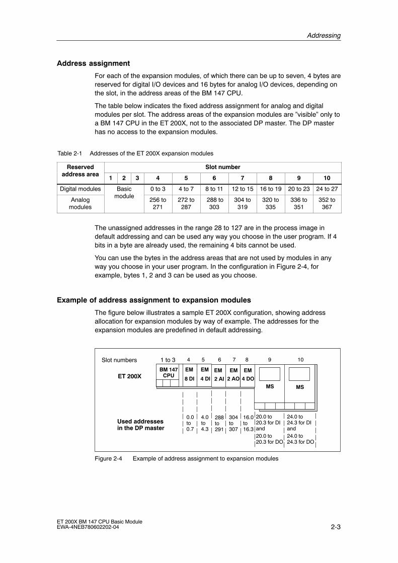
Example of address assignment to expansion modules
The figure below illustrates a sample ET 200X configuration, showing addressallocation for expansion modules by way of example. The addresses for theexpansion modules are predefined in default addressing.
EM EM
8 DI 4 DI
BM 147CPU
EM EM
2 AI 2 AOMS MS
0.0to 0.7
Used addressesin the DP master
Slot numbers 4 5 6 7 8 9
EM
101 to 3
4.0to 4.3
288to 291
304to 307
16.0to 16.3
20.0 to 20.3 for DIand20.0 to 20.3 for DO
24.0 to 24.3 for DIand24.0 to 24.3 for DO
4 DOET 200X
Figure 2-4 Example of address assignment to expansion modules
Addressing
2-4ET 200X BM 147 CPU Basic Module
EWA-4NEB780602202-04
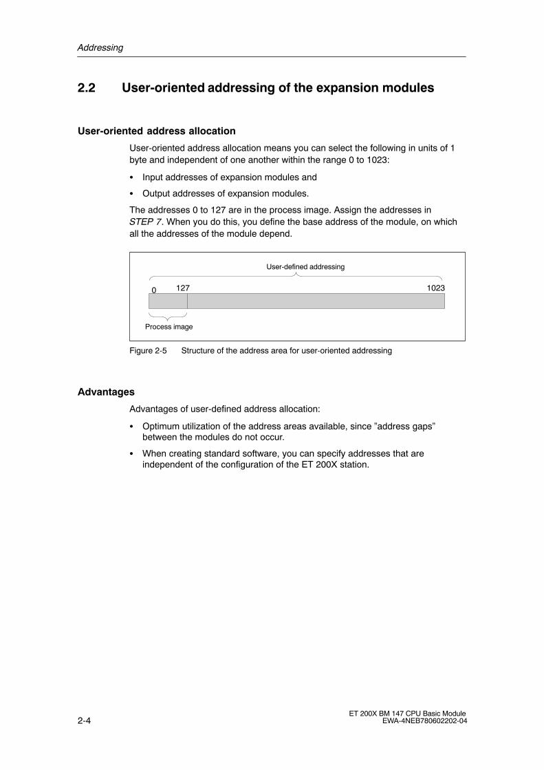
2.2 User-oriented addressing of the expansion modules
User-oriented address allocation
User-oriented address allocation means you can select the following in units of 1byte and independent of one another within the range 0 to 1023:
� Input addresses of expansion modules and
� Output addresses of expansion modules.
The addresses 0 to 127 are in the process image. Assign the addresses inSTEP 7. When you do this, you define the base address of the module, on whichall the addresses of the module depend.
0 127 1023
Process image
User-defined addressing
Figure 2-5 Structure of the address area for user-oriented addressing
Advantages
Advantages of user-defined address allocation:
� Optimum utilization of the address areas available, since �address gaps�between the modules do not occur.
� When creating standard software, you can specify addresses that areindependent of the configuration of the ET 200X station.
Addressing
2-5ET 200X BM 147 CPU Basic ModuleEWA-4NEB780602202-04
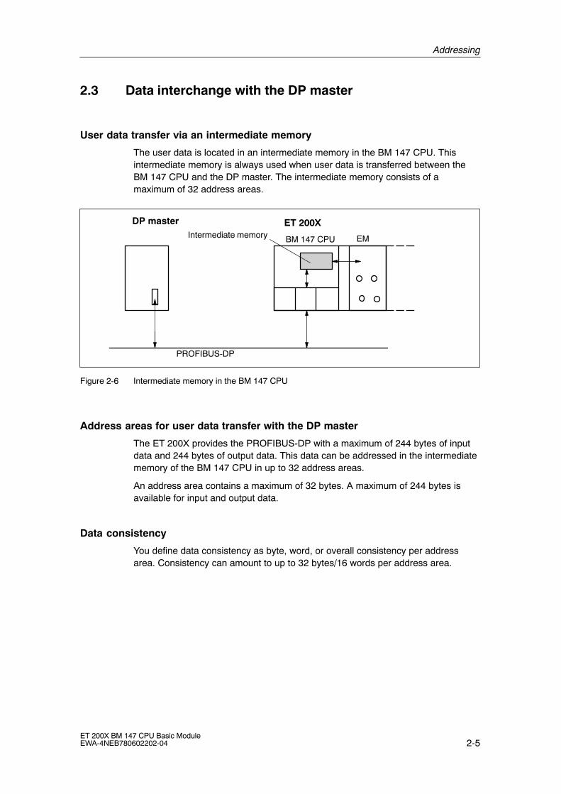
2.3 Data interchange with the DP master
User data transfer via an intermediate memory
The user data is located in an intermediate memory in the BM 147 CPU. Thisintermediate memory is always used when user data is transferred between theBM 147 CPU and the DP master. The intermediate memory consists of amaximum of 32 address areas.
Intermediate memory
PROFIBUS-DP
ET 200XDP master
EMBM 147 CPU
Figure 2-6 Intermediate memory in the BM 147 CPU
Address areas for user data transfer with the DP master
The ET 200X provides the PROFIBUS-DP with a maximum of 244 bytes of inputdata and 244 bytes of output data. This data can be addressed in the intermediatememory of the BM 147 CPU in up to 32 address areas.
An address area contains a maximum of 32 bytes. A maximum of 244 bytes isavailable for input and output data.
Data consistency
You define data consistency as byte, word, or overall consistency per addressarea. Consistency can amount to up to 32 bytes/16 words per address area.

Addressing
2-6ET 200X BM 147 CPU Basic Module
EWA-4NEB780602202-04
DP diagnostic address in STEP 7
When the ET 200X is configured with STEP 7, two diagnostic addresses are set.The ET 200X receives information on the status of the DP master or on a businterruption by means of these diagnostic addresses (see Section 6.5). In DP slavemode, the diagnostic addresses are by default at:
BM 147-1 CPU BM 147-2 CPU
1021
1022
1020
1021
Address for slot 2
Slave diagnosis address
Detailed information can be found in the Online Help for STEP 7 under Slot modelfor I slaves.
Access to free areas in the process image
If you access available but unconfigured process image areas, no process imageerrors will be generated. You can therefore use inputs and outputs in the processimage to which no I/O modules are allocated as markers.

Addressing
2-7ET 200X BM 147 CPU Basic ModuleEWA-4NEB780602202-04
2.4 Accessing the intermediate memory in the BM 147 CPU
Access in the user program
The following table tells you how to access the intermediate memory in theBM 147 CPU from the user program.
Table 2-2 Accessing the address areas
Access dependent on dataconsistency
The following applies
1, 2 or 4-byte data consistencywith load/transfer instructions
All areas parameterized with �unity� consistency can be accessed. Amaximum of 32 bytes of input data can be addressed with loadinstructions and 32 bytes of output data with transfer instructions(L PEB/PEW/PED; T PAB/PAW/PAD; see also Instruction list).
The data consistency for word addressing is 2 bytes; for double-wordaddressing it is 4 bytes.
Access is also possible via the process image.
1- to 32-byte data consistency onthe PROFIBUS-DP with SFC 14and SFC 15
If the address area of consistent data is in the process image, thisarea is updated automatically.
If you want to access data in the intermediate memory, you have toread the input data with SFC 14 �DPRD_DAT� and write the outputdata with SFC 15 �DPWR_DAT�. These SFCs have data consistencyof 1 to 32 bytes.
You can only copy the input data read with SFC 14 as a block of 1 to32 bytes to a memory marker address area, for example, where itcan be addressed with A M x.y. You can also write only one block of1 to 32 bytes as output data with SFC 15 (see also the System andStandard Functions) Reference Manual.
If you access areas with �whole length� consistency, the length in theSFC must correspond to the length of the parameterized area.
It is also possible to address the consistent areas directly (forexample, L PIW or T PQW).
Addressing
2-8ET 200X BM 147 CPU Basic Module
EWA-4NEB780602202-04
Rules for address allocation
You must obey the following rules when allocating addresses for the ET 200X withthe BM 147 CPU:
� Assignment of the address areas:
� Input data for the ET 200X is always output data for the DP master
� Output data for the ET 200X is always input data for the DP master
� You access the data in the user program using load/transfer instructions orSFCs 14 and 15.
� The length, unit and consistency of the associated address areas for the DPmaster and the DP slave must be identical.
� Addresses for the master and the slave can be different in the logically identicalintermediate memory (mutually independent logical I/O address areas in themaster and the slave CPU)
When the BM 147 CPU is configured with STEP 7 for operation in the S5 or innon-Siemens systems, it is clear that only the logical addresses within the slaveCPU are allocated. The addresses are then assigned in the master system usingthe specific configuration tool of the master system.
Addressing interface in STEP 7
The following table illustrates the principles of address allocation. You will also findthis table in the STEP 7 interface. You must set the mode �MS� (for master slave)or �DX� (direct connection) in STEP 7 (see Section 3.5).
Table 2-3 Addressing interface in STEP 7 (extract)
Mode Master PROFIBUS-DP partner Parameters
I/O Address I/O Address Length Unit Consistency
1 MS Q 200 I 128 4 Byte Unit
2 MS Q 300 I 132 8 Byte Total length
3 MS I 700 Q 128 4 Word Unit
4 MS I 50 Q 136 4 Byte Unit
:
7
MS:MasterSlave
Address areas in theDP master CPU
Address areas in theBM 147 CPU
These address area parametersmust be identical for the DP masterand the BM 147 CPU
Addressing
2-9ET 200X BM 147 CPU Basic ModuleEWA-4NEB780602202-04
Sample Program
Below you will see a sample program for data interchange between the DP masterand the DP slave.
You will find the addresses in Table 2-3.
SFCs 14 and 15 are called by specifying the logical address in hexadecimalformat.
in the BM 147 CPU
Data preprocessing in the DP slave:
L 2T MB 6L IB 0T MB 7
Load actual value 2 andtransfer to memory byte 6.Load input byte 0 andtransfer to memory byte 7.
Forward data to DP master
L MW 6T PQW 136
Load memory word 6 andtransfer to peripheral output word 136
in the DP Master CPU
Postprocess received data in the DP master:
L PIB 50T MB 60L PIB 51L B#16#3+ IT MB 61
Load peripheral input byte 50 andtransfer to memory byte 60.Load peripheral input byte 51 andload byte 3;add the values as integer data type andtransfer the result to memory byte 61.
Data preprocessing in the DP master:
L 10+ 3T MB 67
Load actual value 10 andadd 3,transfer the result to memory byte 67.
Send the data (memory bytes 60 to 67) to the DP slave:
CALL SFC 15 LADDR:= W#16#12C RECORD:= P#M60.0 Byte8 RET_VAL:=MW 22
Call system function 15:Write the data to the output address area as ofaddress 300 (12C hexadecimal) with a length of 8bytes as of memory byte 60.
in the BM 147 CPU
Receive data from the DP master (stored in MB 30 to 37):
CALL SFC 14 LADDR:= W#16#84 RET_VAL:=MW 20 RECORD:=P#M30.0 Byte8
Call system function 14:Write the data from the input address area as ofaddress 132 (84 hexadecimal) with a length of 8bytes to memory byte 30.
Postprocess received data:
L MB 30L MB 37+ IT MW 100
Load memory byte 30 andload memory byte 37;add the values as integer data type andtransfer the result to memory byte 100.
Addressing
2-10ET 200X BM 147 CPU Basic Module
EWA-4NEB780602202-04
User data transfer in STOP mode
The user data in the intermediate memory is processed differently depending onwhether the DP master or the DP slave (BM 147 CPU) goes into STOP mode.
� The BM 147 CPU goes into STOP mode: The data in the intermediate memory(outputs only from the slave�s viewpoint) of the BM 147 CPU are overwrittenwith �0�; i.e. the DP master or a recipient in direct communication reads �0�.
� If the DP master goes into STOP mode: The current data in the intermediatememory of the BM 147 CPU (inputs in the slave, outputs in the master) areretained and can be read out in the user program of the BM 147 CPU.
IM 308-C as the DP master (SIMATIC S5)
If you use an IM 308-C as the DP master, the following applies to the interchangeof consistent data:
You must program FB 192 in the IM 308-C to enable the transfer of consistent databetween the DP master and the DP slave. The effect of FB 192 is that the data isonly output or read out by the ET 200X continuously in a single block.
3-1ET 200X BM 147 CPU Basic ModuleEWA-4NEB780602202-04
ET 200X in the PROFIBUS Network
Introduction
You can integrate the ET 200X with the BM 147 CPU as a node in a PROFIBUSnetwork. This chapter contains a description of a typical network configuration withthe BM 147 CPU. It also tells you which functions can be executed via the PD orOP on the ET 200X and which options are available for direct connection. Theavailable communication utilities can be found in Section 7.8.
Equidistance
As of STEP 7 V 5.2 + SP1, you can parameterize bus cycles of the same length(equidistant) for PROFIBUS subnets with BM 147 CPU. You will find a detaileddescription of the functions in the Online Help for STEP 7.
In this chapter
In Section Contents Page
3.1 ET 200X in the PROFIBUS network 3-2
3.2 Network components 3-6
3.3 PROFIBUS address 3-7
3.4 Functions via the PD/OP 3-8
3.5 Direct communication 3-11
More information
You will find more information on the structure of networks in the manual for the DPmaster.
3

ET 200X in the PROFIBUS Network
3-2ET 200X BM 147 CPU Basic Module
EWA-4NEB780602202-04
3.1 ET 200X in the PROFIBUS network
Structure of a PROFIBUS network
The figure below illustrates the basic structure of a PROFIBUS network with oneDP master and several DP slaves.
1 ... 8 PROFIBUS addresses of the nodes
S7-300 (DP master)
ET 200X
8
2 3
4 5 6
S5-95U
ET 200BET 200M
* The ET 200X can be configured and programmed from this programming device
1
PD*
OP 25**
7
** Operating and monitoring functions can be executed on the ET 200X
ET 200X
Figure 3-1 Example of a PROFIBUS network
Hardware requirements in the programming device/OP for accessing theET 200X
Before you can access a BM 147 CPU from a programming device/operator panel,the programming device/operator panel must fulfill the following requirements:
� it must have an integrated PROFIBUS-DP interface or DP card; or
� it must have an integrated MPI interface or MPI card.
ET 200X in the PROFIBUS Network
3-3ET 200X BM 147 CPU Basic ModuleEWA-4NEB780602202-04
Access to the ET 200X
The BM 147 CPU is a passive/active bus node. The programs and configuration ofthe BM 147 CPU can be transferred to the BM 147 CPU by choosing �Load PLC�from the PD in SIMATIC Manager. All the other diagnostic and test functions arealso possible with the PD.
If the PD is currently the only active bus node, this must be set beforehand inSIMATIC Manager by choosing the �Set PD/PC Interface� menu command (seeSection 3.4).
However, you can still install OPs/OSs (operator panels/operator stations) as fixedcomponents of the PROFIBUS network for operating and monitoring functions.
You cannot access an ET 200X from more than 12 devices in parallel:
� 1 connection is reserved for the PD.
� 1 connection is reserved for an OP or an OS.
� 10 connections are available as desired for PDs, OPs/OSs and CPUs.
We recommend that you allocate a PROFIBUS address to the PD/OP in the sameway as for other network nodes (see Figure 3-1).
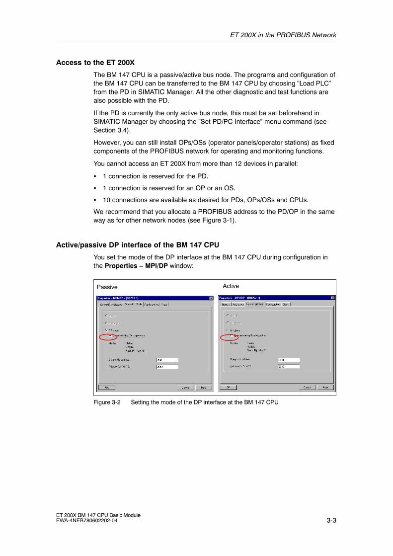
Active/passive DP interface of the BM 147 CPU
You set the mode of the DP interface at the BM 147 CPU during configuration inthe Properties � MPI/DP window:
Passive Active
Figure 3-2 Setting the mode of the DP interface at the BM 147 CPU
ET 200X in the PROFIBUS Network
3-4ET 200X BM 147 CPU Basic Module
EWA-4NEB780602202-04
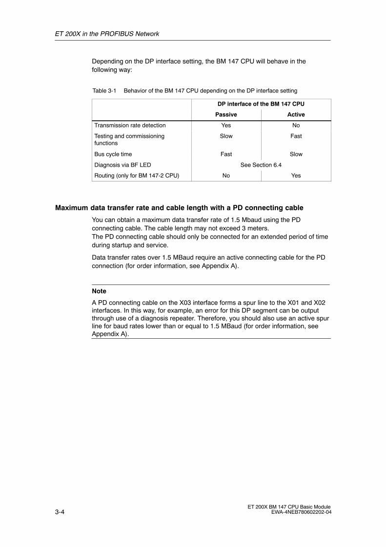
Depending on the DP interface setting, the BM 147 CPU will behave in thefollowing way:
Table 3-1 Behavior of the BM 147 CPU depending on the DP interface setting
DP interface of the BM 147 CPU
Passive Active
Transmission rate detection Yes No
Testing and commissioningfunctions
Slow Fast
Bus cycle time Fast Slow
Diagnosis via BF LED See Section 6.4
Routing (only for BM 147-2 CPU) No Yes
Maximum data transfer rate and cable length with a PD connecting cable
You can obtain a maximum data transfer rate of 1.5 Mbaud using the PDconnecting cable. The cable length may not exceed 3 meters.The PD connecting cable should only be connected for an extended period of timeduring startup and service.
Data transfer rates over 1.5 MBaud require an active connecting cable for the PDconnection (for order information, see Appendix A).
Note
A PD connecting cable on the X03 interface forms a spur line to the X01 and X02interfaces. In this way, for example, an error for this DP segment can be outputthrough use of a diagnosis repeater. Therefore, you should also use an active spurline for baud rates lower than or equal to 1.5 MBaud (for order information, seeAppendix A).

ET 200X in the PROFIBUS Network
3-5ET 200X BM 147 CPU Basic ModuleEWA-4NEB780602202-04
Examples of PD/OP connection to ET 200X
� The PD/OP is connected to the PROFIBUS-DP interface of the DP master, butcan be connected just as well to any other station in the DP network, includingthe ET 200X.
S7-300 (DP master)
ET 200X
PD
Figure 3-3 PD/OP accesses the ET 200X via the DP interface in the DP master
� The PD is directly connected to the ET 200X (you don�t add the ET 200X to thePROFIBUS network until later). Note: Depending on the DP interface (active/passive), a special setting isrequired in STEP 7 (see Section 3.4).
ET 200X
PD
Figure 3-4 The PD directly accesses the ET 200X
� The PD can also be a direct DP node, although a spur line (e.g. PD connectingcable) is not permissible with a transmission rate greater than 1.5 Mbaud. Thisrequires an active spur line.

ET 200X in the PROFIBUS Network
3-6ET 200X BM 147 CPU Basic Module
EWA-4NEB780602202-04
3.2 Network components
To connect the ET 200X to the PROFIBUS-DP network, you will require thenetwork components listed in the Appendix A.
Example of the use of network components
The figure below shows the example from Figure 3-3 with the use of the networkcomponents. Connecting the bus cable to the bus connector is described in theProduct Information document for the bus connector.
ET 200X with BM 147-2 CPU
Bus cable
Bus connector with aPD socket
ECOFAST connector
Bus cable
E.g. enclosureentry
IP 20
IP 67
ET 200X with BM 147-1 CPU
Figure 3-5 Connecting the DP network
ET 200X in the PROFIBUS Network
3-7ET 200X BM 147 CPU Basic ModuleEWA-4NEB780602202-04
3.3 PROFIBUS address
Features
Use the PROFIBUS address to specify the address at which the BM 147 CPU iscontacted on the PROFIBUS-DP.
Prerequisites
� The permitted PROFIBUS-DP addresses are 1 to 125.
� Each address can be allocated only once on the PROFIBUS-DP.
Startup without DP configuration on the Micro Memory Card (MMC) (initialstartup)
Following POWER ON, the coexistent interface on the BM 147 CPU powers up asan MPI interface with the address 2, HSA 31 and 187.5 kBaud. The DP slavefunctionality of the BM 147 CPU is not yet available. All PD functions listed inSection 3.4 are possible with the interface.
Several ET 200X units with BM 147 CPUs as DP slaves on one PROFIBUSnetwork must be commissioned step by step. After each individual BM 147 CPUhas been switched on, STEP 7 must be used to transfer a configuration with DPaddress to the BM 147 CPU.
Note
The bus parameters are retentive, i.e. bus parameters that have been configured(e.g. address, transmission rate) are retained
� with POWER OFF
� if there is no longer a configuration on the BM 147 CPU (e.g. after SDBs havebeen deleted or following POWER ON without MMC)
Startup with DP configuration on the Micro Memory Card (MMC)
As soon as a DP configuration has been downloaded to the BM 147 CPU, the datastored on the MMC is used on startup.
Following POWER ON, the BM 147 CPU as the DP slave powers up with theconfigured address and waits for parameter assignment by the DP master.
As active PROFIBUS node, the BM 147 CPU adopts the configured transmissionrate.As passive PROFIBUS node, the BM 147 CPU searches for the transmission rate.

ET 200X in the PROFIBUS Network
3-8ET 200X BM 147 CPU Basic Module
EWA-4NEB780602202-04
3.4 Functions via the PD/OP
You can use the programming device to:
� Configure the BM 147 CPU with ET 200X modules and put them into operationon the PROFIBUS-DP
� Program the BM 147 CPU.
� Execute test functions such as �Monitor/Modify Variables� and �Program Status�
Execute commissioning functions such as �Start� and �Memory Reset�
� Display the module status (i.e. for the BM 147 CPU, for example, you candisplay the utilization of the load and working memory, stack contents anddiagnostic buffer contents)
You can use the OP to:
� Operate and monitor
You will find a detailed description of the functions in the online help for STEP 7.
Running the BM 147 CPU as a passive DP slave on the PD � required settings inSTEP 7
If you connect a BM 147 CPU directly to a PD, you must set the PD interface inSTEP 7 to allow communication between the two partners. Proceed as follows:
1. In STEP 7, choose the �Setting the PD/PC Interface� tool (Start > STEP 7 >Setting the PD/PC Interface).
2. Set the interface of your PD to PROFIBUS.
3. Call the properties of the PROFIBUS network.
4. Set the properties so that the PD/PC is the only active master on the bus.
Later, after you have configured a DP master for the network and have goneonline, you should reset these settings as this activates additional safety functionsagainst bus faults.

ET 200X in the PROFIBUS Network
3-9ET 200X BM 147 CPU Basic ModuleEWA-4NEB780602202-04
Force test function
In the case of the BM 147 CPU, you can preset the inputs and the outputs in theprocess image with fixed values using the �Force� function.
The values (force values) you have preset can still be controlled in theBM 147 CPU by the user program and by PD/OP functions. This is shown inFigure 3-6.
You can force a maximum of 10 variables with the BM 147 CPU.
!Caution
The force values in the process-image input table can be overwritten by writecommands (for example T IB x, = I x.y, copy with SFC, etc.) as well as by I/O readcommands (L PIW x, for example) in the user program or by PD/OP writefunctions.
Outputs preset with force values only return the force value provided the userprogram does not execute any write accesses to the outputs using I/O writecommands (e.g. T PQB x) and provided no PD/OP functions write to theseoutputs.
It is important to note that force values in the process-image input/output tablecannot be overwritten by the user program or by PD/OP functions.
Principle behind forcing with the BM 147 CPU
Execute forcejob for outputs
PIItransfer User programOS
T PQW
Forced valueoverwritten by TPQW!
Execute forcejob for inputs
Forced value
Execute forcejob for outputs
Forced value
Execute forcejob for inputs
OS .... Operating system execution
PIQtransfer
PIItransfer
OSPIQtransfer
Figure 3-6 Principle behind forcing

ET 200X in the PROFIBUS Network
3-10ET 200X BM 147 CPU Basic Module
EWA-4NEB780602202-04
Application example
Prerequisite: There is no direct I/O access in your user program.
If, for example, an enable sensor (f) in your system is defective and it continuallyindicates a logical 0 to your user program, for example, via input 1.2, you canbridge this sensor by forcing the input to 1, ensuring that your system continues tooperate.
!Warning
However, because the sensor is out of operation, you must monitor thefunctionality by different means to avoid injury to the operator and damage to themachine.
ET 200X in the PROFIBUS Network
3-11ET 200X BM 147 CPU Basic ModuleEWA-4NEB780602202-04
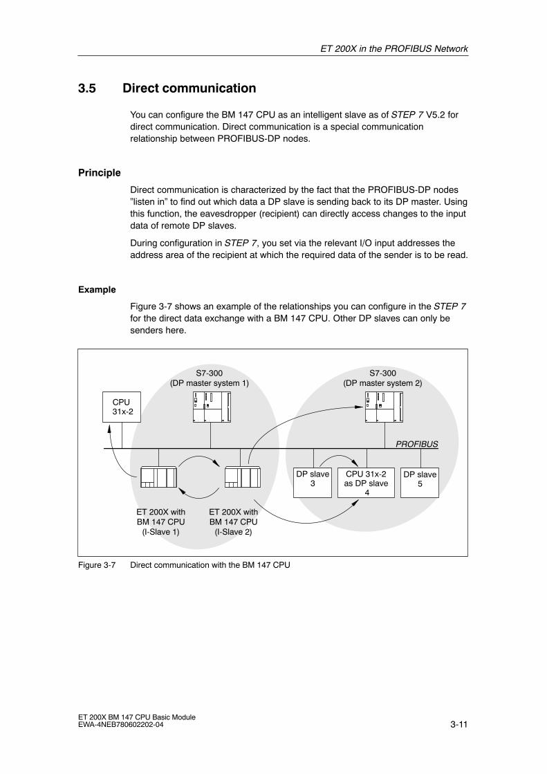
3.5 Direct communication
You can configure the BM 147 CPU as an intelligent slave as of STEP 7 V5.2 fordirect communication. Direct communication is a special communicationrelationship between PROFIBUS-DP nodes.
Principle
Direct communication is characterized by the fact that the PROFIBUS-DP nodes�listen in� to find out which data a DP slave is sending back to its DP master. Usingthis function, the eavesdropper (recipient) can directly access changes to the inputdata of remote DP slaves.
During configuration in STEP 7, you set via the relevant I/O input addresses theaddress area of the recipient at which the required data of the sender is to be read.
Example
Figure 3-7 shows an example of the relationships you can configure in the STEP 7for the direct data exchange with a BM 147 CPU. Other DP slaves can only besenders here.
ET 200X withBM 147 CPU
(I-Slave 2)
S7-300(DP master system 1)
CPU 31x-2
CPU 31x-2 as DP slave
4
DP slave3
S7-300(DP master system 2)
ET 200X withBM 147 CPU
(I-Slave 1)
DP slave5
PROFIBUS
Figure 3-7 Direct communication with the BM 147 CPU

ET 200X in the PROFIBUS Network
3-12ET 200X BM 147 CPU Basic Module
EWA-4NEB780602202-04
Functionality in direct communication
The BM 147 CPU offers the following functionality in direct communication:
� Transmitter:As a DP slave, the BM 147 CPU sends the process outputs, configured fordirect communication, to all bus nodes as a broadcast frame. Other recipientsfilter the relevant data from this broadcast frame.
� Receiver:Filtering of the data from the broadcast frame sent by transmitters which havebeen configured using STEP 7 as being relevant for direct communication.
Diagnostics in direct communication
Only the results of connection monitoring can be used in the diagnostics of the DPslaves configured for direct communication, because diagnostic messages of theDP slaves that have been listened in on are only reported to the DP master.
The asynchronous OB 86 is called in the event of station failure and reintegration.If data is accessed during a station failure of the sender, an I/O access error isdetected and OB 122 is called. Only the identifiers �module plugged� and �moduleavailable� are relevant for the module status data.

4-1ET 200X BM 147 CPU Basic ModuleEWA-4NEB780602202-04
ET 200X in the MPI Network
Introduction
You can integrate the ET 200X with the BM 147 CPU as a node in an MPI network.This chapter contains a description of a typical network configuration with theBM 147 CPU. Section 3.4 describes which functions can be executed on theBM 147 CPU using a PD or OP. The available communication utilities can be foundin Section 7.8.
Information on clock synchronization via the MPI interface is found in the STEP 7Online Help.
In this chapter
In Section Contents Page
4.1 ET 200X in the MPI network 4-2
4.2 MPI address 4-4
4
ET 200X in the MPI Network
4-2ET 200X BM 147 CPU Basic Module
EWA-4NEB780602202-04
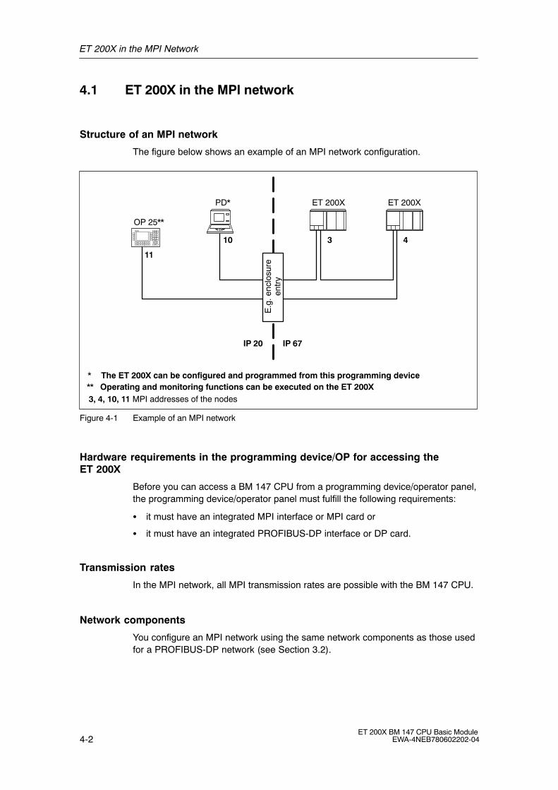
4.1 ET 200X in the MPI network
Structure of an MPI network
The figure below shows an example of an MPI network configuration.
3, 4, 10, 11 MPI addresses of the nodes
ET 200X
10 3
11
* The ET 200X can be configured and programmed from this programming device
PD*
OP 25**
** Operating and monitoring functions can be executed on the ET 200X
ET 200X
4
E.g
. enc
losu
reen
try
IP 20 IP 67
Figure 4-1 Example of an MPI network
Hardware requirements in the programming device/OP for accessing theET 200X
Before you can access a BM 147 CPU from a programming device/operator panel,the programming device/operator panel must fulfill the following requirements:
� it must have an integrated MPI interface or MPI card or
� it must have an integrated PROFIBUS-DP interface or DP card.
Transmission rates
In the MPI network, all MPI transmission rates are possible with the BM 147 CPU.
Network components
You configure an MPI network using the same network components as those usedfor a PROFIBUS-DP network (see Section 3.2).

ET 200X in the MPI Network
4-3ET 200X BM 147 CPU Basic ModuleEWA-4NEB780602202-04
Maximum data transfer rate and cable length with a PD connecting cable
You can obtain a maximum data transfer rate of 1.5 Mbaud using the PDconnecting cable. The cable length may not exceed 3 meters.The PD connecting cable should only be connected for an extended period of timeduring startup and service.
Data transfer rates over 1.5 MBaud require an active connecting cable for the PDconnection (for order information, see Appendix A).
Note
A PD connecting cable on the X03 interface forms a spur line to the X01 and X02interfaces. In this way, for example, an error for this MPI segment can be outputthrough use of a diagnosis repeater. Therefore, you should also use an active spurline for baud rates lower than or equal to 1.5 MBaud (for order information, seeAppendix A).
ET 200X in the MPI Network
4-4ET 200X BM 147 CPU Basic Module
EWA-4NEB780602202-04
4.2 MPI address
Features
With the MPI address, you determine the address under which the BM 147 CPU isaccessed in the MPI network.
Prerequisites
� The permitted MPI addresses are 0 to 126.
� Each address can be allocated only once on the MPI network.
Recommendations for MPI addresses
� Assign MPI addresses greater than �2� to the fixed nodes in the MPI network.
� Reserve the MPI address �0� for a service PD and �1� for a service OP which, ifnecessary, can be connected to the MPI network at short notice.
� Reserve the MPI address �2� for a CPU. This prevents double MPI addressesoccurring when a CPU with default settings is installed in the MPI network (e.g.when a CPU is exchanged).
Startup without configuration on the Micro Memory Card (MMC) (initial startup)
Following POWER ON, the coexistent interface on the BM 147 CPU powers up asan MPI interface with the address 2, HSA 31 and 187.5 kBaud. All PD functionslisted in Section 3.4 are possible with the interface.
Note
The bus parameters are retentive, i.e. bus parameters that have been configured(e.g. address, transmission rate) are retained
� with POWER OFF
� if there is no longer a configuration on the BM 147 CPU (e.g. after SDBs havebeen deleted or following POWER ON without MMC)
Startup with configuration on the Micro Memory Card (MMC)
As soon as a configuration has been downloaded to the BM 147 CPU, the datastored on the MMC is used on startup.
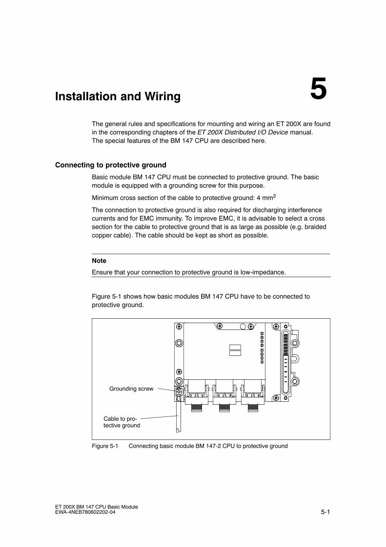
5-1ET 200X BM 147 CPU Basic ModuleEWA-4NEB780602202-04
Installation and Wiring
The general rules and specifications for mounting and wiring an ET 200X are foundin the corresponding chapters of the ET 200X Distributed I/O Device manual.The special features of the BM 147 CPU are described here.
Connecting to protective ground
Basic module BM 147 CPU must be connected to protective ground. The basicmodule is equipped with a grounding screw for this purpose.
Minimum cross section of the cable to protective ground: 4 mm2
The connection to protective ground is also required for discharging interferencecurrents and for EMC immunity. To improve EMC, it is advisable to select a crosssection for the cable to protective ground that is as large as possible (e.g. braidedcopper cable). The cable should be kept as short as possible.
Note
Ensure that your connection to protective ground is low-impedance.
Figure 5-1 shows how basic modules BM 147 CPU have to be connected toprotective ground.
Cable to pro-tective ground
Grounding screw
Figure 5-1 Connecting basic module BM 147-2 CPU to protective ground
5
Installation and Wiring
5-2ET 200X BM 147 CPU Basic Module
EWA-4NEB780602202-04
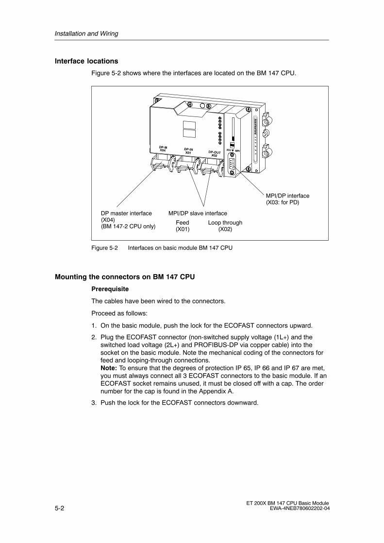
Interface locations
Figure 5-2 shows where the interfaces are located on the BM 147 CPU.
MPI/DP interface(X03: for PD)
DP master interface(X04)(BM 147-2 CPU only)
MPI/DP slave interface
Feed(X01)
Loop through(X02)
Figure 5-2 Interfaces on basic module BM 147 CPU
Mounting the connectors on BM 147 CPU
Prerequisite
The cables have been wired to the connectors.
Proceed as follows:
1. On the basic module, push the lock for the ECOFAST connectors upward.
2. Plug the ECOFAST connector (non-switched supply voltage (1L+) and theswitched load voltage (2L+) and PROFIBUS-DP via copper cable) into thesocket on the basic module. Note the mechanical coding of the connectors forfeed and looping-through connections.Note: To ensure that the degrees of protection IP 65, IP 66 and IP 67 are met,you must always connect all 3 ECOFAST connectors to the basic module. If anECOFAST socket remains unused, it must be closed off with a cap. The ordernumber for the cap is found in the Appendix A.
3. Push the lock for the ECOFAST connectors downward.
Installation and Wiring
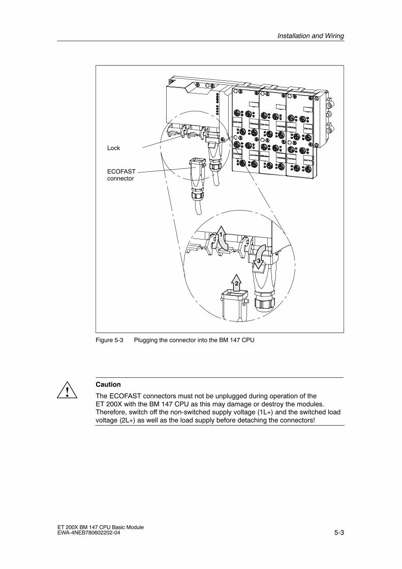
5-3ET 200X BM 147 CPU Basic ModuleEWA-4NEB780602202-04
ECOFASTconnector
Lock
2
1
3
Figure 5-3 Plugging the connector into the BM 147 CPU
!Caution
The ECOFAST connectors must not be unplugged during operation of theET 200X with the BM 147 CPU as this may damage or destroy the modules.Therefore, switch off the non-switched supply voltage (1L+) and the switched loadvoltage (2L+) as well as the load supply before detaching the connectors!
Installation and Wiring
5-4ET 200X BM 147 CPU Basic Module
EWA-4NEB780602202-04
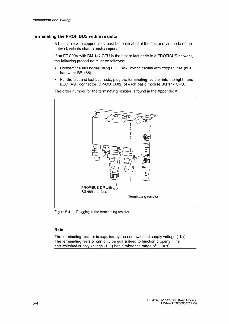
Terminating the PROFIBUS with a resistor
A bus cable with copper lines must be terminated at the first and last node of thenetwork with its characteristic impedance.
If an ET 200X with BM 147 CPU is the first or last node in a PROFIBUS network,the following procedure must be followed:
� Connect the bus nodes using ECOFAST hybrid cables with copper lines (bushardware RS 485).
� For the first and last bus node, plug the terminating resistor into the right-handECOFAST connector (DP-OUT/X02) of each basic module BM 147 CPU.
The order number for the terminating resistor is found in the Appendix A.
Terminating resistor
PROFIBUS-DP withRS 485 interface
Figure 5-4 Plugging in the terminating resistor
Note
The terminating resistor is supplied by the non-switched supply voltage (1L+).The terminating resistor can only be guaranteed to function properly if thenon-switched supply voltage (1L+) has a tolerance range of �10 %.

Installation and Wiring
5-5ET 200X BM 147 CPU Basic ModuleEWA-4NEB780602202-04
Fuse for non-switched supply voltage (1L+)
To protect the modules against overload, the BM 147 CPU is equipped with a fusefor the non-switched supply voltage (1L+).
After blowing of a fuse, the BM 147 CPU behaves as follows:If the fault that led to the fuse blowing (e.g. short circuit at a sensor) is eliminated,the fuse recovers and the BM 147 CPU runs up again.

Installation and Wiring
5-6ET 200X BM 147 CPU Basic Module
EWA-4NEB780602202-04
6-1ET 200X BM 147 CPU Basic ModuleEWA-4NEB780602202-04
Commissioning and Diagnostics
Configuring the BM 147 CPU as a DP slave with STEP 7
An ET 200X with BM 147 CPU is configured differently from an ET 200X withBM 141 or BM 142. Therefore, this chapter briefly describes how to configure aBM 147 CPU with STEP 7.
Resetting the memory of the BM 147 CPU
In certain situations you must reset the memory of the BM 147 CPU. This chapterdescribes these circumstances and the procedure for resetting the memory of theCPU component.
Diagnostic options
The ET 200X distributed I/O device is designed to make handling andcommissioning as simple as possible. If a fault or an error should occur in spite ofthis, you can analyze it using the LEDs, the slave diagnosis and the diagnosticoptions in STEP 7.
Interrupt evaluation
To help you evaluate the interrupts of the ET 200X, we will examine the differencebetween these and the interrupts of the S7/M7 DP master and other DP masters.
Chapter overview
InSection
Contents Page
6.1 Configuring the BM 147 CPU 6-2
6.2 Resetting the memory of the BM 147 CPU 6-5
6.3 Commissioning and start-up of the ET 200X 6-8
6.4 Diagnostics using LEDs 6-13
6.5 Diagnostics via diagnostic address with STEP 7 6-16
6.6 Slave diagnostics with BM 147 CPU as intelligent slave 6-19
6
Commissioning and Diagnostics
6-2ET 200X BM 147 CPU Basic Module
EWA-4NEB780602202-04
6.1 Configuring the BM 147 CPU
Configure the basic module BM 147 CPU as an intelligent DP slave or as astandalone module (MPI) and/or as a DP master (BM 147-2 CPU).
The BM 147 CPU is presented to the user in STEP 7 as an S7-300 module that isalways created together with a rack in an S7-300 station. Similarly, the module canonly be deleted with the rack!
Expansion racks cannot be configured in an S7-300 station that contains aBM 147 CPU. The BM 147 CPU is connected to slot 2 and obtains an MPI/DPsubmodule (BM 147-2 CPU also obtains a DP master submodule). The first plug-inmodules (maximum of 7) can be configured beginning with slot 4.
The following configuration options are available:
Table 6-1 Configuration options
Configurationenvironment
Configuration tool Configurable operating mode
SIMATIC S7 STEP 7 (HWConfig)V5.2 or higher+ Service Pack 1
� Stand-alone (MPI)
� BM 147 CPU as S7 slave
� BM 147-2 CPU as DP master
SIMATIC S5 COM PROFIBUS Fully configured and programmedBM 147 CPU, integrated as astandard intelligent slave via GSDin COM PROFIBUS
Non-Siemenssystems
Non-Siemens tool Fully configured and programmedBM 147 CPU, integrated as astandard intelligent slave via GSDin a non-Siemens tool
Note
If you wish to operate the BM 147 CPU as a standard slave via the GSD file, thenyou should not activate the commissioning/test mode checkbox in the DP interfaceproperties when configuring this slave CPU in STEP 7.
Prerequisite
You have opened STEP 7 (V5.2 or higher + Service Pack 1) and are in theSIMATIC Manager of STEP 7.
Commissioning and Diagnostics
6-3ET 200X BM 147 CPU Basic ModuleEWA-4NEB780602202-04
Configuring the BM 147 CPU as a DP slave
Proceed as follows:
1. Configure the BM 147 CPU as an S7-300 station.
� Create a new station of the type S7-300 (menu command Insert �Station).
� Change to the hardware configuration window for this station.
� In the �Hardware Catalog� window, select the PROFIBUS-DP/ET200X/BM 147 CPU folder.
� Drag and drop the �BM 147 CPU� object in the empty station window.
� Configure the ET 200X with the required expansion modules.
� Save the station (i.e. the ET 200X).
2. Configure a DP master (e.g. CPU with integrated PROFIBUS-DP interface orCP 342-5 with PROFIBUS-DP interface as of 6GK7 342-5DA01-0XE0,version 2) in another station in the same project.
3. Drag the ET 200X (with the BM 147 CPU) from the �Hardware Catalog� window(from the configured stations) and drop it the icon for the DP master system.
4. Double-click the intelligent DP slave icon, and select the �Interconnecting� tab.Specify on this tab which station is to represent the intelligent DP slave.
5. Select the intelligent DP slave, and click the �Interconnect� button.
6. Select the (slave) configuration tab, and assign the master and slaveaddresses.
7. Click �OK� to accept the settings.
8. The two stations must then be reloaded to start master-slave communication.
Configuration in a non-Siemens system
Using the DDB file you can also integrate the BM 147 CPU in non-Siemenssystems as a DP standard slave. In this case the diagnostic frame consists of thefollowing:
� Station status
� Master PROFIBUS address
� Manufacturer ID
� Module diagnostics
� Module status

Commissioning and Diagnostics
6-4ET 200X BM 147 CPU Basic Module
EWA-4NEB780602202-04
Configuring the BM 147-2 CPU as a DP master
The BM 147-2 CPU must be configured as a DP master. This means that you haveto configure interface X04 of the BM 147-2 CPU as a DP master in STEP 7,
� assign the BM 147-2 CPU a PROFIBUS address,
� assign the BM 147-2 CPU a master diagnosis address,
� integrate DP slaves in the DP master system.
Is a BM 147 CPU a DP slave?Then you will find this DP slave in the PROFIBUS-DP catalog as apre-configured station. In the DP master, you assign a slave diagnosisaddress to this DP slave CPU. You have to couple the DP master with the DPslave CPU and define the address ranges for the data exchange with the DPslave CPU.
Commissioning and Diagnostics
6-5ET 200X BM 147 CPU Basic ModuleEWA-4NEB780602202-04
6.2 Resetting the memory of the BM 147 CPU
When do you reset the memory of the BM 147 CPU?
The memory of the BM 147 CPU must be reset
� to erase retentive areas (memory markers, times, counters)
� if the BM 147 CPU requests a memory reset by flashing the STOP LED at0.5 Hz
The following are possible reasons for the MRES request:
� The ET 200X is starting up for the first time.
� Inconsistent memory areas
� The memory module (MMC) has been replaced.
How do you reset the memory?
There are two ways of resetting the BM 147 CPU:
Table 6-2 Ways to reset the memory
Resetting the memory with the modeselector
Resetting the memory with the PD
Described in this chapter. Only possible during CPU STOP (see thePD manuals and the STEP 7 Online Help)
Resetting the memory of the BM 147 CPU with the mode selector
To reset the memory of the BM 147 CPU using the mode selector, proceed asfollows (see also Figure 6-1):
1. Undo the screws on the front panel (captive cross-recessed screws) and openthe panel upwards.
2. Switch the mode selector to the STOP position.
3. Depress the mode selector in the MRES position. Hold the mode selector atthis position until the STOP LED lights up for the second time (3 seconds) andthen let it return to the STOP position.
4. Within 3 seconds, you must press the mode selector back to the MRES positionand hold it in this position until the STOP LED flashes rapidly (at 2 Hz). Whenthe BM 147 CPU has completed the memory reset, the STOP LED stopsflashing and remains on.
5. Select the required operating mode (RUN/STOP).
6. Close the front panel again and screw it shut.
The BM 147 CPU has reset the memory.
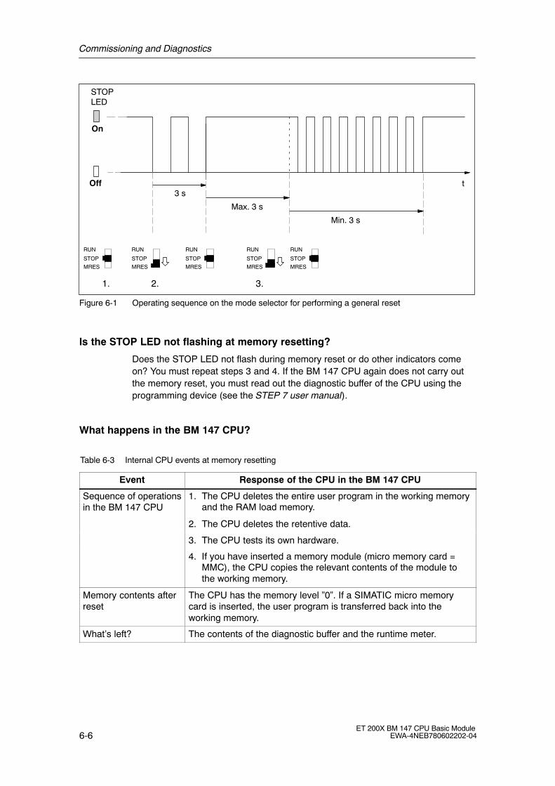
Commissioning and Diagnostics
6-6ET 200X BM 147 CPU Basic Module
EWA-4NEB780602202-04
t
On
Off 3 s
Max. 3 s
Min. 3 s
1. 2. 3.
STOPLED
STOP
MRES
RUN
STOP
MRES
RUN
STOP
MRES
RUN
STOP
MRES
RUN
STOP
MRES
RUN
Figure 6-1 Operating sequence on the mode selector for performing a general reset
Is the STOP LED not flashing at memory resetting?
Does the STOP LED not flash during memory reset or do other indicators comeon? You must repeat steps 3 and 4. If the BM 147 CPU again does not carry outthe memory reset, you must read out the diagnostic buffer of the CPU using theprogramming device (see the STEP 7 user manual).
What happens in the BM 147 CPU?
Table 6-3 Internal CPU events at memory resetting
Event Response of the CPU in the BM 147 CPU
Sequence of operationsin the BM 147 CPU
1. The CPU deletes the entire user program in the working memoryand the RAM load memory.
2. The CPU deletes the retentive data.
3. The CPU tests its own hardware.
4. If you have inserted a memory module (micro memory card =MMC), the CPU copies the relevant contents of the module tothe working memory.
Memory contents afterreset
The CPU has the memory level �0�. If a SIMATIC micro memorycard is inserted, the user program is transferred back into theworking memory.
What�s left? The contents of the diagnostic buffer and the runtime meter.

Commissioning and Diagnostics
6-7ET 200X BM 147 CPU Basic ModuleEWA-4NEB780602202-04
Note
If the CPU cannot copy the contents of the memory module (MMC) and requests amemory reset:
� Remove the MMC.
� Reset the CPU memory.
� Read out the diagnostic buffer.
You can read out the diagnostic buffer with the PD (see the STEP 7 Online Help).
Commissioning and Diagnostics
6-8ET 200X BM 147 CPU Basic Module
EWA-4NEB780602202-04
6.3 Commissioning and start-up of the ET 200X
6.3.1 Starting up the BM 147 CPU as a DP slave
Commissioning the ET 200X
Commission the ET 200X distributed I/O device as follows:
1. Install the ET 200X distributed I/O device (see the ET 200X Distributed I/O Device manual)).
2. Wire the ET 200X distributed I/O device(see Chapter5 and the ET 200X Distributed I/O Device) manual.
3. During configuration as a DP slave, specify in the configuration software theaddress areas in the BM 147 CPU via which data exchange with the DP masteris to take place (or use the ET 200X default setting; see Section 2.4).
4. Switch on the non-switched supply voltage for the electronics/sensors (1L+)and the switched load voltage (2L+) for the ET 200X.
5. If necessary, switch on the load voltage and the load supply voltage for themotor starters.
6. If necessary, switch the BM 147 CPU to STOP mode.
7. Load the configuration for the BM 147 CPU in the ET 200X.
8. Switch the BM 147 CPU to RUN mode.
Setting the bus parameters for the PROFIBUS-DP in STEP 7
Note
To comply with the values required for electromagnetic compatibility, you must setthe following bus parameter in STEP 7 for the 500 kBaud and 1.5 MBaudbaudrates:
�Retry Limit� to at least �3�
Leave all the other bus parameters as they are, in accordance with your selectedbus profile.

Commissioning and Diagnostics
6-9ET 200X BM 147 CPU Basic ModuleEWA-4NEB780602202-04
Tip: Programming OB 82 and 86 during commissioning
Always program OB 82 and OB 86 when commissioning as a DP slave in the DPmaster and DP slave using STEP 7. This will allow you to detect and evaluate theoperating states of and interruptions during user data transfer (see Tables 6-7 and6-8).
Note
Without configuration, a default start-up is possible if the power modules areswitched on and all the modules are inserted.
6.3.2 Starting up the BM 147-2 CPU as a DP master
Commissioning
Commission the BM 147-2 CPU as a DP master in the PROFIBUS subnet asfollows:
1. Switch the supply voltage on.
2. Load the configuration of the PROFIBUS subnet (preset configuration) createdwith STEP 7 into the BM 147-2 CPU with the PD.
3. Switch all DP slaves on.
4. Switch the BM 147-2 CPU from STOP to RUN mode.
Initializing the DP master system
In addition, the initialization time monitor for the DP slave can be set with theMonitoring time for transfer of parameters to modules parameter.
This means that the DP slaves must be initialized and parameterized by theBM 147-2 CPU (as DP master) within the set time period.
Commissioning and Diagnostics
6-10ET 200X BM 147 CPU Basic Module
EWA-4NEB780602202-04
Start-up of the BM 147-2 CPU as a DP master
When it starts up, the BM 147-2 CPU compares the preset configuration of the DPmaster system with the actual configuration.
If the preset configuration � the actual configuration, the CPU goes into RUNmode.
If the preset configuration � the actual configuration, the behavior of the CPUdepends on the setting of the Start-up when the preset configuration � actualconfiguration parameter.
Start-up when preset configuration �actual configuration � yes
(default setting)
Start-up when preset configuration �actual configuration � no
BM 147-2 CPU goes into RUN mode.
(BF-LED on the DP master module flashesif all DP slaves cannot be addressed.)
BM 147-2 CPU remains in STOP mode andthe BF-LED on the DP master moduleflashes after the set Monitoring time fortransfer of parameters to modules haselapsed.
A flashing BF-LED indicates that at leastone DP slave cannot be addressed. Checkwhether all DP slaves are switched on andthat they correspond to the definedconfiguration, or read out the diagnosticbuffer using STEP 7.
Recognizing the operating modes of the DP slave (event recognition)
The table below shows how the BM 147-2 CPU identifies changes in operatingmode and interruptions in data transfer as a DP master.
Table 6-4 Event recognition of the BM 147-2 CPU as a DP master
Event What takes place in the DP master?
Bus interruption(short-circuit,connectorremoved)
� OB 86 is called and Station failure is reported
(incoming event; diagnosis address of the DP slave assigned tothe DP master)
� In the case of I/O access: OB 122 is called
(I/O access error)
DP slave:
RUN → STOP
� OB 82 is called and Module malfunction reported
(incoming event; diagnosis address of the DP slave assigned tothe DP master; variable OB82_MDL_STOP=1)
DP slave:
STOP → RUN
� OB 82 is called and Module ok reported.
(outgoing event; diagnosis address of the DP slave assigned tothe DP master; variable OB82_MDL_STOP=0)
Tip:Always program OB 82 and OB 86 when commissioning the CPU as a DP master.This will allow you to detect and evaluate the faults and interruptions during datatransfer.
Commissioning and Diagnostics
6-11ET 200X BM 147 CPU Basic ModuleEWA-4NEB780602202-04
Status/controlling, programming via PROFIBUS-DP
You can program the CPU or execute the PD functions listed in Chap. 3.4 via theDP master interface.
Note
The use of status and control via the DP master interface extends the DP cycle.
Equidistance
As of STEP 7 V 5.2 + SP1, you can parameterize bus cycles of the same length(equidistant) for PROFIBUS subnets with BM 147 CPU. You will find a detaileddescription of the functions in the Online Help for STEP 7.
PROFIBUS address of the DP master
� The permitted PROFIBUS-DP addresses are 1 to 125.
� Each address can be allocated only once on the PROFIBUS-DP.

Commissioning and Diagnostics
6-12ET 200X BM 147 CPU Basic Module
EWA-4NEB780602202-04
6.3.3 Start-up
Loading the user program
When commissioning the ET 200X, you can download the user program to theBM 147 CPU in the following ways:
� The program is downloaded from the PD/PC to the memory module (MMC)inserted in the BM 147 CPU by means of the �Load user program� function.
Note
This function does not delete retentive areas.
� The program is transferred from the PD/PC to the memory module (MMC). Thememory module is then inserted in the BM 147 CPU and the memory resetrequest acknowledged.
See Section 7.3.
Start-up
When the BM 147 CPU is switched to RUN mode, the following mutuallyindependent operating mode transitions take place:
� The CPU switches from STOP to RUN mode.
� The BM 147 CPU starts user data transfer with the DP master on thePROFIBUS-DP.
� The BM 147-2 CPU starts user data transfer with the DP slaves on thePROFIBUS-DP.

Commissioning and Diagnostics
6-13ET 200X BM 147 CPU Basic ModuleEWA-4NEB780602202-04
6.4 Diagnostics using LEDs
LEDs
The LEDs RUN, STOP, ON, 24 VDC, BF-S, BF-M, SF and FRCE displayimportant information on the states of the BM 147 CPU.
The BM 147 CPU has the following 8 LEDs:
� �SF� LED (System Fault) for indicating the presence of a fault in the ET 200X
� LEDs �BF-S� and �BF-M� (Bus Fault) for indicating the presence of faults in thePROFIBUS-DP (�BF-M� only for BM 147-2 CPU)
BF-S: Bus fault on slave strand BF-M: Bus fault on master strand
� LED �ON� for indicating that the ET 200X is connected to a non-switched supplyvoltage for electronics/sensors (1L+)
� LED �24 VDC� for indicating that the ET 200X is connected to a switched loadvoltage (2L+)
� �FRCE� LED for indicating that a force request is active.
� �RUN� LED for indicating that the BM 147 CPU is in RUN mode
� �STOP� LED for indicating that the BM 147 CPU is in STOP mode
The meaning of the LEDs for CPU functionality is described in detail in Section 7.2.
Figure 6-2 Position of LEDs on basic module BM 147 CPU
�ON� LED is Off
If the �ON� LED is off, either no supply voltage or insufficient non-switched supplyvoltage is being applied to the electronic components/sensors (1L+) of the ET200X. The cause is likely to be a defective fuse or inadequate or nonexistentsystem voltage.
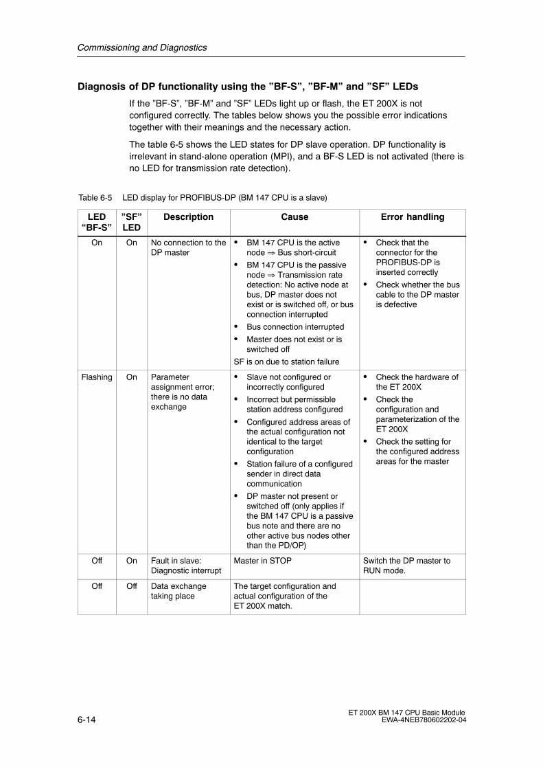
Commissioning and Diagnostics
6-14ET 200X BM 147 CPU Basic Module
EWA-4NEB780602202-04
Diagnosis of DP functionality using the �BF-S�, �BF-M� and �SF� LEDs
If the �BF-S�, �BF-M� and �SF� LEDs light up or flash, the ET 200X is notconfigured correctly. The tables below shows you the possible error indicationstogether with their meanings and the necessary action.
The table 6-5 shows the LED states for DP slave operation. DP functionality isirrelevant in stand-alone operation (MPI), and a BF-S LED is not activated (there isno LED for transmission rate detection).
Table 6-5 LED display for PROFIBUS-DP (BM 147 CPU is a slave)
LED�BF-S�
�SF�LED
Description Cause Error handling
On On No connection to theDP master
� BM 147 CPU is the activenode ⇒ Bus short-circuit
� BM 147 CPU is the passivenode ⇒ Transmission ratedetection: No active node atbus, DP master does notexist or is switched off, or busconnection interrupted
� Bus connection interrupted
� Master does not exist or isswitched off
SF is on due to station failure
� Check that theconnector for thePROFIBUS-DP isinserted correctly
� Check whether the buscable to the DP masteris defective
Flashing On Parameterassignment error;there is no dataexchange
� Slave not configured orincorrectly configured
� Incorrect but permissiblestation address configured
� Configured address areas ofthe actual configuration notidentical to the targetconfiguration
� Station failure of a configuredsender in direct datacommunication
� DP master not present orswitched off (only applies ifthe BM 147 CPU is a passivebus note and there are noother active bus nodes otherthan the PD/OP)
� Check the hardware ofthe ET 200X
� Check theconfiguration andparameterization of theET 200X
� Check the setting forthe configured addressareas for the master
Off On Fault in slave:Diagnostic interrupt
Master in STOP Switch the DP master toRUN mode.
Off Off Data exchangetaking place
The target configuration andactual configuration of theET 200X match.

Commissioning and Diagnostics
6-15ET 200X BM 147 CPU Basic ModuleEWA-4NEB780602202-04
The table 6-6 shows the LED states for DP master operation.
Table 6-6 LED display for PROFIBUS-DP (BM 147-2 CPU is a master)
LED�BF-M�
�SF�LED
Description Cause Error handling
On On No connection to theDP slave
� Bus connectioninterrupted
� Slave does not exist or isswitched off
� Bus short-circuit
� Check that the connectorfor the PROFIBUS-DP isinserted correctly
� Check whether the buscable to the DP master isdefective
� Evaluate the diagnosis.Reconfigure or correct theconfiguration.
Flashing On � There is no dataexchange
� Parameterassignment error
� A connected station hasfailed
� At least one of theassigned slaves cannotbe addressed
� Configured address areasof the actual configurationnot identical to the targetconfiguration
� Check whether the buscable is connected to theCPU or the bus isinterrupted.
� Wait until the CPU has runup. If the LED does notstop flashing, check theDP slaves or evaluate thediagnosis of the DPslaves.
� Check the setting for theconfigured address areasfor the master

Commissioning and Diagnostics
6-16ET 200X BM 147 CPU Basic Module
EWA-4NEB780602202-04
6.5 Diagnostics via diagnostic address with STEP 7
Malfunctions that occur in the ET 200X are indicated by the �SF� LED, and thecause is entered in the diagnostic buffer of the BM 147 CPU. Either the CPUenters STOP mode, or you can respond to errors by means of error or interruptOBs in the user program.
To enable a response to be made, it must be possible to identify whatever causedthe problem by means of a diagnostic address.
Diagnostic addresses
If you run the ET 200X with a DP master from the SIMATIC S7 range on thePROFIBUS-DP, diagnostic addresses are assigned in STEP 7 as follows:
You specify two diagnostic addresses during configuration:
PROFIBUS
ET 200XDP master (SIMATIC S7)
Diagnostic address Diagnostic address
When configuring the DP master, you specify(in the associated project for the DP master)a diagnostic address for the ET 200X.
During configuration of the ET 200X, STEP 7sets the diagnostic address for slot 2 to 1021by default for the ET 200X (in the associatedproject for the ET 200X).
The DP master receives information on thestatus of the ET 200X or on a businterruption by means of this diagnosticaddress.
The ET 200X receives information on the status ofthe DP master by means of this diagnosticaddress.
Figure 6-3 Diagnostic addresses for the DP master and ET 200X

Commissioning and Diagnostics
6-17ET 200X BM 147 CPU Basic ModuleEWA-4NEB780602202-04
Event identification
The following table indicates how the DP master or the BM 147 CPU of theET 200X identifies changes in operating mode and interruptions in user datatransfer.
Table 6-7 Responses to operating mode changes and interruptions in user data transfer in the DPmaster and the ET 200X with the BM 147 CPU
EventWhat happens ...
Eventin the DP master in the BM 147 CPU
Bus interruption(short-circuit,connectorremoved)
� OB 86 is called with the messageStation failure (incoming event; diagnostic address of theBM 147 CPU)
� With I/O access to transfer area:OB 122 is called (I/O access error)
� OB 86 is called with the messageStation failure (incoming event; diagnostic addressof the BM 147 CPU)
� With I/O access to transfer area:OB 122 is called (I/O access error)
ET 200X: RUN → STOP
� OB 82 is called with the messageFaulty module(incoming event; diagnostic address of theBM 147 CPU; variableOB82_MDL_STOP=1)
�
ET 200X: STOP → RUN
� OB 82 is called with the messageModule ok.(outgoing event; diagnostic address of theBM 147 CPU; variable OB82_MDL_STOP=0)
�
DP master: RUN → STOP
� � OB 82 is called with the messageFaulty module(incoming event; diagnostic address of theBM 147 CPU; variableOB82_MDL_STOP=1)
DP master: STOP → RUN
� � OB 82 is called with the messageModule ok.(outgoing event; diagnostic address of theBM 147 CPU; variable OB82_MDL_STOP=0)

Commissioning and Diagnostics
6-18ET 200X BM 147 CPU Basic Module
EWA-4NEB780602202-04
Evaluation in the user program
The table below indicates how you can evaluate e.g. RUN-STOP transitions in theDP master (CPU 315-2 DP; 6ES7 315-2AF03-0AB0) and in the ET 200X.
Table 6-8 Evaluation of RUN/STOP Transitions in the DP Master/ET 200X
In the DP master In the ET 200X (BM 147-1 CPU)
Diagnostic addresses: (example)Master diagnostic address=1023Slave diagnostic address in the mastersystem=1022
Diagnostic addresses: (example)Slave diagnostic address, slot 2=1021Master diagnostic address=not relevant
The CPU calls OB 82 with the followinginformation:
� OB 82_MDL_ADDR:=1022
� OB82_EV_CLASS:=B#16#39(incoming event)
� OB82_MDL_DEFECT:=Module fault
Tip: This information is available in thediagnostic buffer of the CPU.
In the user program, you should also programSFC 13 (�DPNRM_DG�) to read out the slavediagnosis.
CPU in the BM 147 CPU: RUN → STOP
The CPU generates a diagnostic frame (slavediagnosis; see the ET 200X Distributed I/ODevice manual).
CPU: RUN → STOP The BM 147 CPU calls OB 82 withinformation including the following:
� OB 82_MDL_ADDR:=1021
� OB82_EV_CLASS:=B#16#39(incoming event)
� OB82_MDL_DEFECT:=Module fault
Tip: This information is available in thediagnostic buffer of the CPU.

Commissioning and Diagnostics
6-19ET 200X BM 147 CPU Basic ModuleEWA-4NEB780602202-04
6.6 Slave diagnostics with BM 147 CPU as intelligent slave
Structure of the diagnostic frame
Byte 0Byte 1 Station status 1 to 3Byte 2
Byte 3 Master PROFIBUS address
Byte 4Byte 5 Low byte
High byteManufacturer ID
Byte 6to
Module diagnostics
Byte x-1
Interrupt status (station diagnosis)
.
.
.
.
.
.
Byte xtoByte y-1
(the length depends on thenumber of address areasconfigured for the intermediatememory2))
(the length depends on the typeof interrupt)
2) Exception: If the DP master is incorrectly configured, the DP slave interprets 35 configured address areas (46H in byte 6).
.
.
.
Byte ytoByte z
(the length depends on thenumber of configured addressareas)
Module status (station diagnosis)
Figure 6-4 Format of the slave diagnostic data

Commissioning and Diagnostics
6-20ET 200X BM 147 CPU Basic Module
EWA-4NEB780602202-04
6.6.1 Station status 1 to 3
Definition
Station status 1 to 3 provides an overview of the status of a DP slave.
Station status 1
Table 6-9 Structure of station status 1 (byte 0)
Bit Description Remedy
0 1: DP slave cannot be addressed byDP master.
� Is the correct DP address configured for theDP slave?
� Is the bus connector inserted?
� Does the DP slave have power?
� Is the RS 485 repeater correctly set?
� Execute a reset on the DP slave.
1 1: DP slave is not ready for datainterchange.
� Wait; the DP slave is still doing its run-up.
2 1: The configuration data which theDP master sent to the DP slave donot correspond with the DP slave�sactual configuration.
� Correct station type or correct configurationof the DP slave entered in the configurationsoftware?
3 1: Diagnostic interrupt, generated byRUN-STOP transition of the CPU orby the SFB 75
0: Diagnostic interrupt, generated bySTOP-RUN transition of the CPU orby the SFB 75
� You can read out the diagnostic data.
4 1: Function is not supported, forinstance changing the DP addressat the software level.
� Check the configuration data.
5 0: This bit is always �0�. �
6 1: DP slave type does not correspondto the software configuration.
� Was the configuration software set for theright station type? (parameter assignmenterror)
7 1: DP slave was parameterized by adifferent DP master to the one thatcurrently has access to it.
� Bit is always �1� when, for instance, you arecurrently accessing the DP slave via the PDor a different DP master.
The DP address of the master thatparameterized the slave is located in the�Master PROFIBUS address� diagnosticbyte.
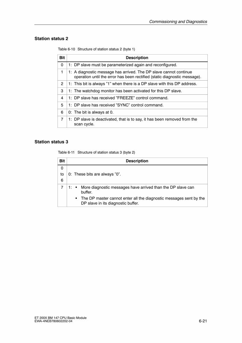
Commissioning and Diagnostics
6-21ET 200X BM 147 CPU Basic ModuleEWA-4NEB780602202-04
Station status 2
Table 6-10 Structure of station status 2 (byte 1)
Bit Description
0 1: DP slave must be parameterized again and reconfigured.
1 1: A diagnostic message has arrived. The DP slave cannot continueoperation until the error has been rectified (static diagnostic message).
2 1: This bit is always �1� when there is a DP slave with this DP address.
3 1: The watchdog monitor has been activated for this DP slave.
4 1: DP slave has received �FREEZE� control command.
5 1: DP slave has received �SYNC� control command.
6 0: The bit is always at 0.
7 1: DP slave is deactivated, that is to say, it has been removed from thescan cycle.
Station status 3
Table 6-11 Structure of station status 3 (byte 2)
Bit Description
0
to
6
0: These bits are always �0�.
7 1: � More diagnostic messages have arrived than the DP slave canbuffer.
� The DP master cannot enter all the diagnostic messages sent by theDP slave in its diagnostic buffer.
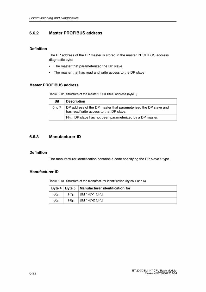
Commissioning and Diagnostics
6-22ET 200X BM 147 CPU Basic Module
EWA-4NEB780602202-04
6.6.2 Master PROFIBUS address
Definition
The DP address of the DP master is stored in the master PROFIBUS addressdiagnostic byte:
� The master that parameterized the DP slave
� The master that has read and write access to the DP slave
Master PROFIBUS address
Table 6-12 Structure of the master PROFIBUS address (byte 3)
Bit Description
0 to 7 DP address of the DP master that parameterized the DP slave andhas read/write access to that DP slave.
FFH: DP slave has not been parameterized by a DP master.
6.6.3 Manufacturer ID
Definition
The manufacturer identification contains a code specifying the DP slave�s type.
Manufacturer ID
Table 6-13 Structure of the manufacturer identification (bytes 4 and 5)
Byte 4 Byte 5 Manufacturer identification for
80H F7H BM 147-1 CPU
80H F8H BM 147-2 CPU
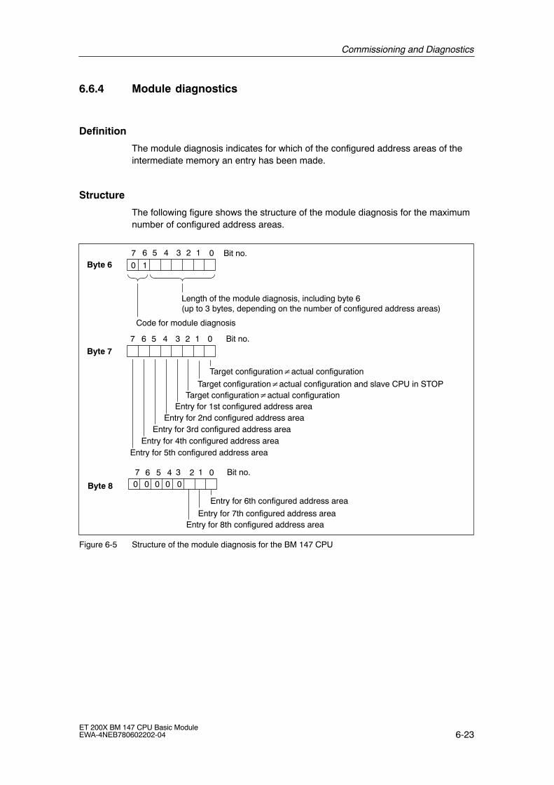
Commissioning and Diagnostics
6-23ET 200X BM 147 CPU Basic ModuleEWA-4NEB780602202-04
6.6.4 Module diagnostics
Definition
The module diagnosis indicates for which of the configured address areas of theintermediate memory an entry has been made.
Structure
The following figure shows the structure of the module diagnosis for the maximumnumber of configured address areas.
Byte 67 0 Bit no.
Length of the module diagnosis, including byte 6 (up to 3 bytes, depending on the number of configured address areas)
Byte 7
Target configuration�actual configuration and slave CPU in STOP
Code for module diagnosis
0 1
7 6 5 4 13
Entry for 1st configured address area
Bit no.
Target configuration�actual configuration
Target configuration�actual configuration
Entry for 2nd configured address areaEntry for 3rd configured address area
Entry for 4th configured address areaEntry for 5th configured address area
2 0
6 5 4 13 2
Bit no.
Byte 8
7 136 5 4 2 0
Entry for 7th configured address areaEntry for 8th configured address area
Entry for 6th configured address area
0 0 0 0 0
Figure 6-5 Structure of the module diagnosis for the BM 147 CPU
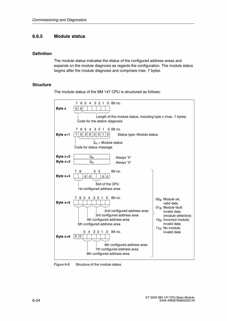
Commissioning and Diagnostics
6-24ET 200X BM 147 CPU Basic Module
EWA-4NEB780602202-04
6.6.5 Module status
Definition
The module status indicates the status of the configured address areas andexpands on the module diagnosis as regards the configuration. The module statusbegins after the module diagnosis and comprises max. 7 bytes.
Structure
The module status of the BM 147 CPU is structured as follows:
7 06 5 4 13 2
Byte x
Byte x+2Byte x+3
0H
0H
Byte x+4
00B: Module ok;valid data
01B: Module fault;invalid data(module defective)
10B: Incorrect module;invalid data
11B: No module;invalid data
Always �0�
Always �0�
Bit no.
Code for the station diagnosis
0 0
Length of the module status, including byte x (max. 7 bytes)
Bit no.
Slot of the CPU
000 0
7 06 5 4 13 2
Byte x+1
Bit no.
1 0 1 00 0 0 0
2H = Module statusCode for status message
Status type: Module status
7 6
1st configured address area
Byte x+5Bit no.7 06 5 4 13 2
3rd configured address area2nd configured address area
4th configured address area5th configured address area
Byte x+6Bit no.
00
05 4 13 2
7th configured address area6th configured address area
8th configured address area
3 2
Figure 6-6 Structure of the module status

Commissioning and Diagnostics
6-25ET 200X BM 147 CPU Basic ModuleEWA-4NEB780602202-04
6.6.6 Interrupt status
Definition
The interrupt status of the station diagnosis provides detailed information about aDP slave. The station diagnosis begins at byte y and can comprise max. 20 bytes.You have 4 bytes available for an interrupt event that you can program as required.
Structure
The following figure shows the structure and content of the bytes for a configuredaddress area of the intermediate memory.
Byte y+1 01H: Code for diagnostic interrupt02H: Code for process interrupt
Byte y+4
Byte y
Length of the interrupt status, including byte y(max. 20 bytes)
Code for the station diagnosis
0 0
Byte y+2 Slot no.:2 = CPU4 ... 11 = No. of configured
address area of intermediate memory
Diagnostic and interrupt data
Byte y+3 000 000
to
Byte y+7
Fordiagnosticinterruptonly
7 06 5 4 13 2 Bit no.
7 06 5 4 13 2 Bit no.
7 06 5 4 13 2 Bit no.00 = No further information
on diagnostic status01 = Incoming diagnosis
(at least 1 faultexists)
10 = Outgoing diagnosis11 = Outgoing diagnosis, but
another fault exists
.
.
.Byte z
Example of byte y+2:CPU = 02H1st address area = 04H2nd address area = 05H etc.
Figure 6-7 Structure of the interrupt status

Commissioning and Diagnostics
6-26ET 200X BM 147 CPU Basic Module
EWA-4NEB780602202-04
Structure of the interrupt data with process interrupt (from Byte y+4 onwards)
With the process interrupt (in byte y+1, code 02H stands for a process interrupt),the 4 byte interrupt information which you transfer in the intelligent slave with theSFC 7 �DP_PRAL� and SFB 75 �SALRM� when the process interrupt is generatedfor the master, is transferred from byte y+4 onwards.
Structure of the interrupt data when a diagnostic interrupt is generated by amode change at the intelligent slave (from Byte y+4 onwards)
In the byte y+1, the code stands for diagnostic interrupt (01H). The diagnostic datacontains the 16 byte status information for the CPU. The following figure shows theassignment of the first 4 bytes of the diagnostic data. The next 12 bytes are always0.
The content of these bytes corresponds to the content of data record 0 fordiagnosis in STEP 7 (in this case not all bits are assigned).
Byte y+4
Byte y+5
Byte y+6
0: Operating mode RUN1: Operating mode STOP
0: BM 147 CPU o.k.1: BM 147 CPU faulty
0
1
0 0 0 0
1
0 0
0 0 00 01
Identifier for the address area of theintermediate memory (constant)
0000000
Byte y+7 0 0 0 0 00 0 0
7 06 5 4 13 2 Bit no.
7 06 5 4 13 2 Bit no.
7 06 5 4 13 2 Bit no.
7 06 5 4 13 2 Bit no.
Figure 6-8 Byte y+4 to y+7 for the diagnostic interrupt (changed operating status of the
intelligent slave)
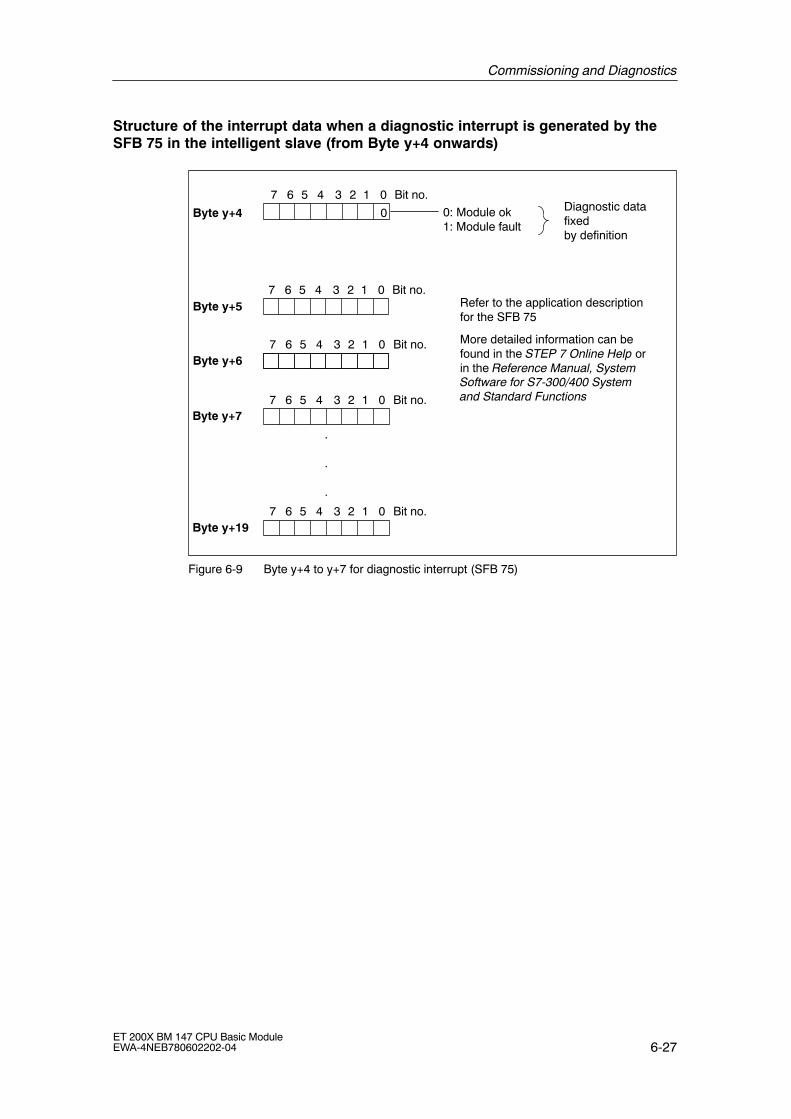
Commissioning and Diagnostics
6-27ET 200X BM 147 CPU Basic ModuleEWA-4NEB780602202-04
Structure of the interrupt data when a diagnostic interrupt is generated by theSFB 75 in the intelligent slave (from Byte y+4 onwards)
Byte y+5
Byte y+6
0: Module ok1: Module fault
0
Refer to the application descriptionfor the SFB 75
More detailed information can befound in the STEP 7 Online Help orin the Reference Manual, SystemSoftware for S7-300/400 Systemand Standard Functions
Byte y+7
7 06 5 4 13 2 Bit no.
7 06 5 4 13 2 Bit no.
7 06 5 4 13 2 Bit no.
7 06 5 4 13 2 Bit no.
Diagnostic datafixedby definition
Byte y+197 06 5 4 13 2 Bit no.
.
.
.
Byte y+4
Figure 6-9 Byte y+4 to y+7 for diagnostic interrupt (SFB 75)

Commissioning and Diagnostics
6-28ET 200X BM 147 CPU Basic Module
EWA-4NEB780602202-04
7-1ET 200X BM 147 CPU Basic ModuleEWA-4NEB780602202-04
Functions of the BM 147 CPU
In this chapter
In this chapter you will find:
� Important features of the BM 147 CPU for PROFIBUS-DP
� A list of the CPU functions of the BM 147 CPU that you can call with STEP 7,such as the integrated clock, blocks for the user program and parameters thatcan be set
Chapter overview
InSection
Contents Page
7.1 Data for the PROFIBUS-DP 7-2
7.2 The mode selector and LEDs 7-4
7.3 SIMATIC Micro Memory Card 7-6
7.4 Memory concept 7-13
7.5 Interface 7-27
7.6 Clock 7-29
7.7 S7 connections 7-30
7.8 Communication 7-35
7.9 Routing 7-39
7.10 Data consistency 7-42
7.11 Blocks 7-43
7.12 Parameters 7-45
7
Functions of the BM 147 CPU
7-2ET 200X BM 147 CPU Basic Module
EWA-4NEB780602202-04
7.1 Data for the PROFIBUS-DP
DDB (Device Database) file
A device master file contains all the slave-specific properties. The structure of theDDB file is defined in IEC 61784-1:2002 Ed1 CP 3/1.
You only need the DDB file if:
� You are using the ET 200X with a DP master from the SIMATIC S5 range(configuration with COM PROFIBUS).
� You are using the ET 200X with a non-SIMATIC DP master (configuration with anon-Siemens tool).
You can download the DDB file from the Internet. You will find all the DDB filesunder �Downloads� on the SIMATIC Customer Support web site: http://www.ad.siemens.de/csi/gsd
Important features
If you do not have the device master file to hand, the table below lists the mostimportant features of the BM 147 CPU.
Feature DP code word toIEC 61784-1:2002 Ed1 CP 3/1
BM 147 CPU
Manufacturer ID Ident_Number 80F7H/80F8H
Supports FMS FMS_supp No
Supports 9.6 kbaud 9.6_supp Yes
Supports 19.2 kbaud 19.2_supp Yes
Supports 45.45 kbaud 45.45_supp Yes
Supports 93.75 kbaud 93.75_supp Yes
Supports 187.5 kbaud 187.5_supp Yes
Supports 500 kbaud 500_supp Yes
Supports 1.5 Mbaud 1.5M_supp Yes
Supports 3 Mbaud 3M_supp Yes
Supports 6 Mbaud 6M_supp Yes
Supports 12 Mbaud 12M_supp Yes
Supports the FREEZE control command Freeze_Mode_supp Yes
Supports the SYNC control command Sync_Mode_supp Yes
Supports automatic transmission rate detection Auto_Baud_supp Yes
PROFIBUS address modifiable by software Set_Slave_Add_supp No
Length of user-specific parameter assignment data User_Prm_Data_Len 3 bytes
User-specific parameter assignment data User_Prm_Data Yes
Minimum interval between slave list rotations Min_Slave_Intervall 1(100�s)
Modular device Modular_Station 1
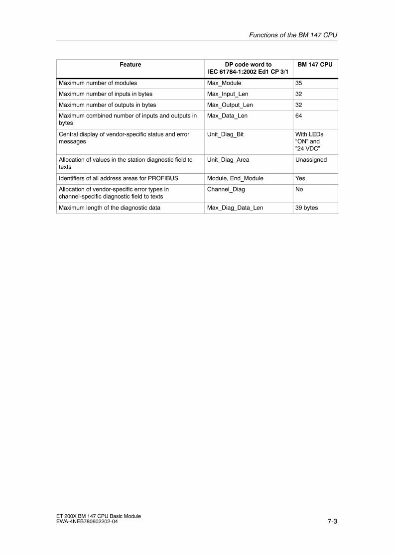
Functions of the BM 147 CPU
7-3ET 200X BM 147 CPU Basic ModuleEWA-4NEB780602202-04
Feature BM 147 CPUDP code word toIEC 61784-1:2002 Ed1 CP 3/1
Maximum number of modules Max_Module 35
Maximum number of inputs in bytes Max_Input_Len 32
Maximum number of outputs in bytes Max_Output_Len 32
Maximum combined number of inputs and outputs inbytes
Max_Data_Len 64
Central display of vendor-specific status and errormessages
Unit_Diag_Bit With LEDs�ON� and�24 VDC�
Allocation of values in the station diagnostic field totexts
Unit_Diag_Area Unassigned
Identifiers of all address areas for PROFIBUS Module, End_Module Yes
Allocation of vendor-specific error types inchannel-specific diagnostic field to texts
Channel_Diag No
Maximum length of the diagnostic data Max_Diag_Data_Len 39 bytes

Functions of the BM 147 CPU
7-4ET 200X BM 147 CPU Basic Module
EWA-4NEB780602202-04
7.2 The mode selector and LEDs
Mode selector
The mode selector of the BM 147 CPU is located behind the front panel. It isdesigned as a 3-step toggle switch as shown below:
RUNSTOPMRES
Figure 7-1 Mode selector
Positions of the mode selector
The positions of the mode selector are explained in the order in which they arearranged on the BM 147 CPU.
Table 7-1 Positions of the mode selector
Position Description Description
RUN RUN mode The CPU processes the user program.
STOP STOP mode The CPU processes no user program.
Programs can:
� Be read out from the CPU using a PD (CPU � PD)
� Transferred to the CPU (PD � CPU)
MRES Reset CPUmemory
Momentary-contact position of the mode selector for resetting theCPU memory.
You must adhere to a specific sequence when resetting the CPUmemory using the mode selector (see Section 6.2)

Functions of the BM 147 CPU
7-5ET 200X BM 147 CPU Basic ModuleEWA-4NEB780602202-04
Meanings of the LEDs for CPU functionality
For the BM 147 CPU there are 2 separate LEDs, which indicate the operatingmode of the CPU:
� RUN
� STOP
You can obtain information on the power supply of the CPU, on force requests andon general errors via 3 additional LEDs.
Table 7-2 LEDs for CPU functionality
LED Description Description
ON (green) Power on Comes on when the supply voltage is applied to the CPU
RUN (green) RUN mode Shines continuously when the CPU is not processing the userprogram.
Flashes at 2 Hz during CPU start-up:
� For at least 3 secs, but the CPU start-up can also be shorter.
� During the CPU start-up the STOP LED also lights up; whenthe STOP LED goes off, the outputs are enabled.
Flashes at 0.5 Hz when the CPU has reached a breakpoint youhave set. At the same time the STOP LED comes on.
STOP (yellow) STOP mode Comes on when the CPU
� is not processing a user program.
� Has reached a breakpoint you have set At the same time theRUN LED flashes at 0.5 Hz
Flashes at 0.5Hz, when the CPU requests a memory reset (seeSection 6.2).
FRCE (yellow) Force requestactive
Lights up when a force request is active.
SF (red) Group error Lights up in the event of
� Programming errors
� Parameter assignment errors
� Calculation errors
� Timing errors
� I/O errors
� Hardware errors
� Firmware errors
To determine the exact nature of the error/fault, you have to use aPD and read out the contents of the diagnostic buffer.
Meanings of other LEDs
The �SF� (from the PROFIBUS-DP point of view), �BF-S�, �BF-M�, �ON� and �24VDC� LEDs are described in Chapter 6.4.

Functions of the BM 147 CPU
7-6ET 200X BM 147 CPU Basic Module
EWA-4NEB780602202-04
7.3 SIMATIC Micro Memory Card
Micro Memory Card
A SIMATIC Micro Memory Card (MMC) is used as a memory module for theBM 147 CPU. The MMC can be used as a load memory and portable data carrier.It is an essential requirement for operating the BM 147 CPU. The following data isstored on the MMC:
� User program (all blocks)
� Archives and recipes
� Configuration data (STEP 7 projects)
� Data for an operating system update, operating system backup
Note
On one MMC you can store either user and configuration data or the operatingsystem.
Copy protection
The MMC has an internal serial number for the purpose of providing MMC copyprotection at the user level. You can read out this serial number from the SZL partslist, 011CH Index 8, using the SFC 51 RDSYSST.
For example, you can program a STOP command in a know-how protected blockfor the event that the set and actual serial number of the MMC do not match.
More detailed information can be found in the SZL parts list in the instructions listor in the System and Standard Functions manual.

Functions of the BM 147 CPU
7-7ET 200X BM 147 CPU Basic ModuleEWA-4NEB780602202-04
Features
The SIMATIC micro memory card ensures zero maintenance and retentivity for theBM 147 CPU. More detailed information can be found in Section 7.4.
!Caution
The module content of a SIMATIC micro memory card can be corrupted if the cardis removed while a write operation is being performed. The MMC must then beerased at the PD or formatted in the BM 147 CPU.
Never remove the MMC in RUN mode; it should only be removed when theBM 147 CPU is in the POWER OFF or STOP mode and only if the PD is notcurrently performing a write access operation. If in the STOP mode you are notsure whether or not the PD is currently performing a write access operation (e.g.loading/erasing a block), unplug the communication connections beforehand.
Service life of an MMC
The service life of an MMC mainly depends on the following factors:
1. The number of erasing and programming operations
2. External influences such as the ambient temperature
At an ambient temperature of up to 60 °C, the service life of an MMC with max.100,000 erase/write operations is 10 years.
!Caution
To prevent data loss, never exceed the maximum number of erase/writeoperations.
1

Functions of the BM 147 CPU
7-8ET 200X BM 147 CPU Basic Module
EWA-4NEB780602202-04
Compatible SIMATIC Micro Memory Cards
The following memory modules are available:
Table 7-3 Available MMCs
Type Order numbers
MMC 64k 6ES7 953-8LF00-0AA0
MMC 128k 6ES7 953-8LG00-0AA0
MMC 512k 6ES7 953-8LJ00-0AA0
MMC 2M 6ES7 953-8LL00-0AA0
MMC 4M 6ES7 953-8LM00-0AA0
MMC 8M 6ES7 953-8LP10-0AA0
The MMCs with a 4 MByte and 8 MByte memory are required for a firmwareupdate.
Functions of the BM 147 CPU
7-9ET 200X BM 147 CPU Basic ModuleEWA-4NEB780602202-04
Formatting the MMC prior to a memory reset
In the following exceptional cases, you have to format the MMC:
� The module type is not a user module.
� The MMC has not been formatted yet.
� The MMC is faulty.
� The content of the MMC is invalid.
The content of the MMC is designated as invalid, if
� the Load User Program operation has been interrupted by POWER OFF.
� the Promming operation has been interrupted by POWER OFF.
� a fault occurs during evaluation of the module content prior to a memory reset.
� a fault occurs during formatting, or formatting could not be performed.
If one of the above-described faults has occurred, the CPU also requests anothermemory reset after a memory reset has been performed. The content of the cardis retained until the formatting has been completed, unless the Load User Programor Promming operations are interrupted by POWER OFF.
Format the MMC as follows:
When the BM 147 CPU requests a memory reset (the STOP LED flashes slowly),format it by operating the selector switch as follows:
1. Set the selector switch to the MRES position and hold it there(approx. 9 seconds) until the STOP LED remains lit (stops flashing).
2. Within the next 3 seconds you must release the selector switch and move itback to the MRES position. The STOP LED flashes during the formattingprocedure.
Make sure that you perform the steps in the specified time, otherwise theMMC will not be formatted and will reassume the Memory Reset status.
The MMC is only formatted if a formatting condition (see above) exists and not e.g.when a memory reset is requested after a module is changed. In this case,switching to MRES only results in a standard memory reset whereby the content ofthe module remains valid.

Functions of the BM 147 CPU
7-10ET 200X BM 147 CPU Basic Module
EWA-4NEB780602202-04
Inserting/changing the card
The MMC is designed so that it can also be removed and inserted when the poweris on. The BM 147 CPU must, however, be switched to the STOP mode (see thewarning on page 7-7). The chamfered edge of the MMC prevents the card beinginserted the wrong way round (reverse polarity protection).
The module slot and the mode selector are located behind the front panel on theBM 147 CPU. You can gain access to both elements by undoing the screws on thefront panel and opening the panel.
There is an eject button on the memory card slot to enable you to remove the cardeasily. To eject the card, press the eject button with a small screwdriver or aball-point pen.
���������� �� Micro
Mem
oryC
ard
�������
������� Ejector
BM 147 CPUMMC
Memory cardslot
Figure 7-2 Position of the memory card slot for the MMC on the BM 147 CPU
If a new MMC is inserted in the memory card slot, the BM 147 CPU requests amemory reset.

Functions of the BM 147 CPU
7-11ET 200X BM 147 CPU Basic ModuleEWA-4NEB780602202-04
Firmware update with MMC
To update the firmware, proceed as follows:
Table 7-4 Firmware update with MMC
Step Action required Action by the BM 147 CPU:
1. Transfer update files to a blankMMC using STEP 7 and yourprogramming device (� 4 MB).
-
2. Deenergize the BM 147 CPU andinsert the MMC with the FWupdate.
-
3. Switch the power on The BM 147 CPU automaticallydetects the MMC with the FWupdate and starts the FW update.
All LEDs light up during the FWupdate.
The STOP LED flashes after theFW update has been completed.In this way, the BM 147 CPUrequests a memory reset.
4. Deenergize the BM 147 CPU andunplug the MMC with the FWupdate.
-
5. Switch on the power supply again. The BM 147 CPU performs anautomatic memory reset and isthen ready for operation.
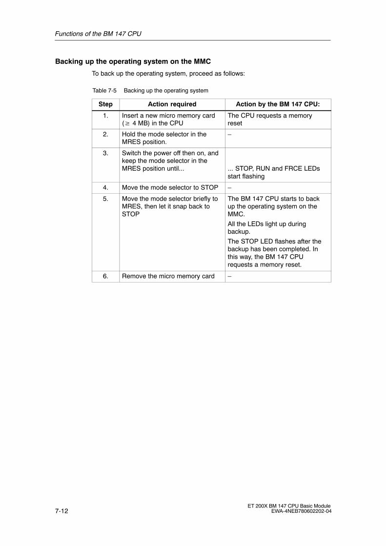
Functions of the BM 147 CPU
7-12ET 200X BM 147 CPU Basic Module
EWA-4NEB780602202-04
Backing up the operating system on the MMC
To back up the operating system, proceed as follows:
Table 7-5 Backing up the operating system
Step Action required Action by the BM 147 CPU:
1. Insert a new micro memory card (� 4 MB) in the CPU
The CPU requests a memoryreset
2. Hold the mode selector in theMRES position.
�
3. Switch the power off then on, andkeep the mode selector in theMRES position until... ... STOP, RUN and FRCE LEDs
start flashing
4. Move the mode selector to STOP �
5. Move the mode selector briefly toMRES, then let it snap back toSTOP
The BM 147 CPU starts to backup the operating system on theMMC.
All the LEDs light up duringbackup.
The STOP LED flashes after thebackup has been completed. Inthis way, the BM 147 CPUrequests a memory reset.
6. Remove the micro memory card �

Functions of the BM 147 CPU
7-13ET 200X BM 147 CPU Basic ModuleEWA-4NEB780602202-04
7.4 Memory concept
7.4.1 Memory areas of the BM 147 CPU
Organization
The memory of the BM 147 CPU can be divided into three areas:
MMC
Load memory
BM 147 CPUWorking memory
System memory
Figure 7-3 Memory areas of the BM 147 CPU
Load memory
The load memory is installed on a SIMATIC micro memory card (MMC). It is usedto record code and data blocks as well as system data (configuration, connections,module parameters, etc.).
Blocks which are designated as non-process-related are recorded in the loadmemory.
The complete configuration data for a project can also be stored on the MMC.
Your program in the load memory (MMC) is always retentive. When downloaded, itis stored on the MMC such that it is unaffected by power failures and is not erasedby memory resets.
Note
The BM 147 CPU can only be operated with the MMC inserted.

Functions of the BM 147 CPU
7-14ET 200X BM 147 CPU Basic Module
EWA-4NEB780602202-04
Working memory
The working memory is integrated on the CPU and cannot be expanded. It is usedto process the codes and data of the user program. Program processing is onlyperformed at the working memory and system memory.
The working memory of the CPU is retentive if the MMC is inserted.
Your data in the working memory is saved on the MMC if the power supply isinterrupted.
System memory
The system memory is integrated on the CPU and cannot be expanded.
It contains
� the address areas �memory markers�, �timers� and �counters�
� the process images of the inputs and outputs
� the local data
For memory markers, timers and counters, you can configure (Properties of theCPU, Retentivity tab) which parts are to be retentive and which parts are to beinitialized with �0� when a complete restart (warm restart) is performed.
The diagnostic buffer, MPI address (and transmission rate) as well as the run-timemeter are generally stored in the retentive memory area on the CPU. Retentivity ofthe MPI address and transmission rate ensures that your CPU is still able tocommunicate following a power failure, a memory reset or the loss ofcommunication parameters (by removing the MMC or erasing the communicationparameters).
Retentivity
The BM 147 CPU has a retentive memory. The retentivity is provided on the MMCand CPU.
The retentivity means that the content of the retentive memory is retained evenfollowing POWER OFF and a restart (warm restart).

Functions of the BM 147 CPU
7-15ET 200X BM 147 CPU Basic ModuleEWA-4NEB780602202-04
Retentive behavior of the memory objects
The following table shows the retentive behavior of the memory objects during theindividual operating mode transitions.
Table 7-6 Retentive behavior of the memory objects
Memory object Operating mode transition
POWEROFF/
POWER ON
STOP →RUN
Memoryreset
User program/data (load memory) X X X
Current values of the DBs Can be set in the DBproperties using STEP 7V5.2 + SP1 (see below)
�
Memory markers, timers and countersconfigured as retentive
X X �
Diagnostic buffers, run-time meters X X X
MPI address, transmission rate X X X
x = retentive; � = not retentive
Retentive behavior of a DB in BM 147 CPU
For BM 147 CPU, you can use STEP 7 (as of version 5.2 + SP1) or the SFC 82�CREA_DBL� (Parameter ATTRIB → Bit NON_RETAIN) to set whether, forPOWER OFF/ON or STOP → RUN, a DB is to
� retain the current values (retentive DB) or
� adopt the initial values from the load memory (non-retentive DB).
Table 7-7 Retentive behavior of the DBs in BM 147 CPU
In the event of a POWER OFF/ON or a CPU restart, the DB is to
Receive the initial values(non-retentive DB)
Retain the last current values(retentive DB)
Background:
In the event of a POWER OFF/ON or a CPUrestart (STOP → RUN), the current valuesof the DB are not retentive. The DB receivesthe initial values from the load memory.
Background:
In the event of a POWER OFF/ON or a CPUrestart (STOP → RUN), the current valuesof the DB are retained.
Prerequisite in STEP 7:
� The �Non-Retain� checkbox is activatedin the block properties of the DB or
� A non-retentive DB was generated withthe SFC 82 �CREA_DBL� and theassociated block attribute (ATTRIB →Bit NON_RETAIN).
Prerequisite in STEP 7:
� The �Non-Retain� checkbox is notactivated in the block properties of theDB or
� A retentive DB was generated with theSFC 82.

Functions of the BM 147 CPU
7-16ET 200X BM 147 CPU Basic Module
EWA-4NEB780602202-04
7.4.2 Memory functions
Introduction
You use the memory functions to generate, modify or erase user programs andindividual blocks. The memory functions also allow you to archive your own projectdata in order to ensure the retentivity of your data.
General: Downloading the user program using the PD/PC
The complete user program is downloaded to the BM 147 CPU from the MMCusing the PD/PC. In certain situations, all of the blocks stored in the load memorymay be erased when the user program is downloaded.
In the load memory, blocks occupy the space specified under �Load MemoryRequirement� in the �General Block Properties�.
Programming device
Load memory Working memoryStored onthe hard disk
Code blocks
Data blocks
Comments
Symbols
Code blocks
Data blocks
Process-relatedparts of the code
and datablocks
MMC
���������� �� Micro
Mem
oryC
ard
�������
�������
Figure 7-4 Load and working memory
The program cannot be started until all of the blocks have been loaded.
Note
The function is only permitted when the CPU is in STOP mode.
The load memory remains empty if loading could not be completed owing to apower failure or invalid blocks.

Functions of the BM 147 CPU
7-17ET 200X BM 147 CPU Basic ModuleEWA-4NEB780602202-04
Downloading a user program to the MMC using the PD/PC
Case A: Downloading a new user programYou have created a new user program. Download the complete program to theMMC using the PD/PC.
Case B: Reloading blocksYou have already created a user program and downloaded it to the MMC (case A).You can then add further blocks to the user program. To do so, you do not have todownload the complete user program to the MMC again; you only have to reloadthe new blocks to the MMC (this method shortens the loading time in the case ofvery complex programs!).
Case C: OverloadingIn this case, you make changes to blocks of your user program. You then overloadthe user program or only the modified blocks to the MMC using the PD/PC.
!Warning
When blocks/a user program are overloaded, all of the data stored on the MMCunder the same name is lost.
When a block has been downloaded, the content in the case of process-relatedblocks is transferred to the working memory and activated.
Erasing blocks
When a block is erased, it is deleted from the load memory. It is possible to erasedata blocks from the user program (SFC 23 �DEL_DB�).
If memory in the working memory has been occupied by this block, this memory isreleased.
Uploading
Unlike downloading, uploading involves loading individual blocks or a completeuser program from the CPU to the PD/PC. In this case, the blocks have the samecontent as when last downloaded to the MMC. Process-related data blocks are theexception; they receive the current values.
Uploading blocks or the user program from the CPU using STEP 7 does not haveany effect on the memory assignment of the CPU.

Functions of the BM 147 CPU
7-18ET 200X BM 147 CPU Basic Module
EWA-4NEB780602202-04
Compression
Compression fills any gaps between memory objects which are formed by loadingand erasing operations in the load and working memory. Contiguous areas of freememory are then available.
Compression is possible when the CPU is in both the STOP and RUN mode.
Promming (RAM to ROM)
With promming, the current values of the data blocks are transferred from theworking memory to the load memory where they serve as new initial values for theDB.
Note
The function is only permitted when the CPU is in STOP mode.
The load memory remains empty if the function could not be completed owing to apower failure.

Functions of the BM 147 CPU
7-19ET 200X BM 147 CPU Basic ModuleEWA-4NEB780602202-04
Removing/inserting the MMC
The BM 147 CPU cannot run if there is no MMC inserted in the BM 147 CPU (noload memory available). Practical operation is only possible if an MMC has beeninserted and a memory reset has been performed.
Removal and insertion of an MMC is detected by the BM 147 CPU in all operatingmodes.
Removing:
1. The BM 147 CPU must be in the STOP mode.
2. The PD must not be performing any write access operations (e.g. loadingblocks)
3. When the MMC is removed, the BM 147 CPU requests a memory reset
!Caution
The module content of a SIMATIC micro memory card can be corrupted if the cardis removed while a write operation is being performed. The MMC must then beerased at the PD or formatted in the BM 147 CPU.
Never remove the MMC in RUN mode; it should only be removed when theBM 147 CPU is in the POWER OFF or STOP mode and only if the PD is notcurrently performing a write access operation. If in the STOP mode you are notsure whether or not the PD is currently performing a write access operation (e.g.loading/erasing a block), unplug the communication connections beforehand.
Inserting:
The MMC with the appropriate user program is inserted as follows:
1. Insert the MMC
2. The BM 147 CPU requests a memory reset
3. Acknowledge the memory reset
If the BM 147 CPU requests a memory reset again owing to an incorrect MMCor an MMC with a firmware update being inserted, proceed as described inSection 7.3 under Special measure.
4. Start the BM 147 CPU
!Warning
Make sure that the MMC to be inserted contains the user program appropriate forthe BM 147 CPU (for the system). An incorrect user program can have seriouseffects on processing.

Functions of the BM 147 CPU
7-20ET 200X BM 147 CPU Basic Module
EWA-4NEB780602202-04
Memory reset
A memory reset restores defined conditions following removal/insertion of themicro memory card so that the BM 147 CPU can be restarted (warm restart).
When the memory is reset, the memory administration system of the BM 147 CPUis reorganized. All blocks of the load memory are retained. All process-relatedblocks are transferred again from the load memory to the working memory; thisinitializes the data blocks in the working memory (they receive their initial valuesfrom the load memory again).
The memory reset procedure and the special points associated with it aredescribed in Section 6.2.
Restart (warm restart)
� All DBs retain their current values.
� All retentive Ms, Cs and Ts retain their values.
� All non-retentive user data is initialized:
� M, C, T, I, O with �0�
� All processing levels start from the beginning.
� The process images are erased.

Functions of the BM 147 CPU
7-21ET 200X BM 147 CPU Basic ModuleEWA-4NEB780602202-04
7.4.3 Address areas
Overview
The system memory of the BM 147 CPU id divided into address areas (see thetable below). In your program, you use the appropriate operations to address thedata directly in the respective address area.
Table 7-8 Address areas of the system memory
Address area Description
Process image of the inputs At the beginning of each OB 1 cycle, the BM 147 CPUreads the inputs out of the input modules and stores thevalues in the process image of the inputs.
Process image of the outputs During the cycle, the program calculates the values for theoutputs and stores them in the process image of theoutputs. At the end of the OB 1 cycle, the BM 147 CPUwrites the calculated output values to the output modules.
Memory markers This area provides memory for intermediate resultscalculated in the program.
Timers Timers are available in this area.
Counter Counters are available in this area.
Local data This memory area records the temporary data of a codeblock (OB, FB, FC) during the period in which this block isbeing processed.
Data blocks See Section 7.4.4
The Instruction list tells you which address areas are possible with your CPU.

Functions of the BM 147 CPU
7-22ET 200X BM 147 CPU Basic Module
EWA-4NEB780602202-04
Process image of the inputs and outputs
If the address areas �inputs� (I) and �outputs� (O) are addressed in the userprogram, the signal states on the digital expansion modules are not checked, butinstead a memory area in the system memory of the CPU is accessed. Thismemory area is referred to as the process image.
The process image is divided into two parts: the process image of the inputs andthe process image of the outputs.
Advantages of the process image
The advantage of accessing the process image over accessing the expansionmodules directly is that a consistent image of the process signals is available to theCPU for the duration of cyclic program processing. If a signal state at an inputmodule changes during program processing, the signal state is retained in theprocess image until the process image is updated in the next cycle. Furthermore,accessing the process image requires much less time than accessing theexpansion modules directly because the process image is located in the systemmemory of the CPU.
Updating the process image
The process image is updated by the operating system cyclically. The figure belowshows the processing steps within a cycle.
Startup programStartup
PIQ
PII
User program
CCP (OpSy)
Cyc
le t
ime
The process image of the outputs is written to theexpansion modules
The inputs are read from the expansion modulesand the data is updated in the process image of theinputs
The user program is processed (OB 1 and blockscalled therein)
Figure 7-5 Processing steps within a cycle
Functions of the BM 147 CPU
7-23ET 200X BM 147 CPU Basic ModuleEWA-4NEB780602202-04
Local data
The following are stored as local data:
� The temporary variables of code blocks
� The start information of the organization blocks
� Transfer parameters
� Intermediate results
Temporary variables
When creating blocks, you can declare temporary variables (TEMP) which are onlyavailable while the block is being processed and are then overwritten again. Thislocal data has a fixed length for each OB. The local data must be initialized beforethe first read access operation. Furthermore, each organization block requires 20bytes for its start information. Local data is accessed faster than data in the DBs.
The BM 147 CPU has memory for the temporary variables (local data) of blocksthat have just been processed. This memory is divided equally between the priorityclasses. Each priority class has its own local data area.
!Caution
All temporary variables (TEMP) of an OB and its subordinate blocks are stored inthe local data. The local data area could overflow if you use a large number ofnesting levels for block processing. The BM 147 CPU changes to the STOP mode if you exceed the permitted quantityof local data in a priority class. Take into consideration the amount of local data required by the synchronous faultOBs. In each case, the local data requirement is assigned to the responsiblepriority class.
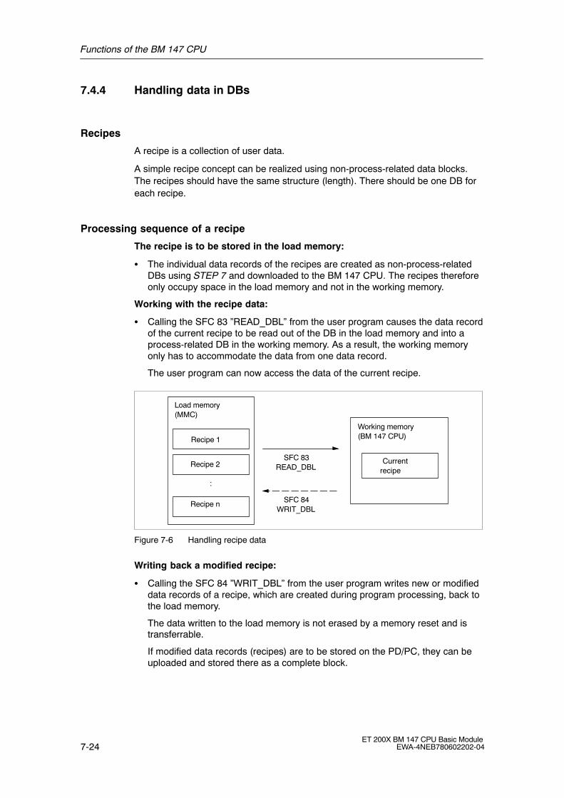
Functions of the BM 147 CPU
7-24ET 200X BM 147 CPU Basic Module
EWA-4NEB780602202-04
7.4.4 Handling data in DBs
Recipes
A recipe is a collection of user data.
A simple recipe concept can be realized using non-process-related data blocks.The recipes should have the same structure (length). There should be one DB foreach recipe.
Processing sequence of a recipe
The recipe is to be stored in the load memory:
� The individual data records of the recipes are created as non-process-relatedDBs using STEP 7 and downloaded to the BM 147 CPU. The recipes thereforeonly occupy space in the load memory and not in the working memory.
Working with the recipe data:
� Calling the SFC 83 �READ_DBL� from the user program causes the data recordof the current recipe to be read out of the DB in the load memory and into aprocess-related DB in the working memory. As a result, the working memoryonly has to accommodate the data from one data record.
The user program can now access the data of the current recipe.
Load memory(MMC)
Recipe 1
Recipe 2
:
Recipe n
Working memory(BM 147 CPU)
Currentrecipe
SFC 83READ_DBL
SFC 84WRIT_DBL
Figure 7-6 Handling recipe data
Writing back a modified recipe:
� Calling the SFC 84 �WRIT_DBL� from the user program writes new or modifieddata records of a recipe, which are created during program processing, back tothe load memory.
The data written to the load memory is not erased by a memory reset and istransferrable.
If modified data records (recipes) are to be stored on the PD/PC, they can beuploaded and stored there as a complete block.

Functions of the BM 147 CPU
7-25ET 200X BM 147 CPU Basic ModuleEWA-4NEB780602202-04
Measured value archives
Measured values are created when the user program is processed by theBM 147 CPU. These measured values are to be archived and evaluated.
Processing sequence of a measured value archive
Collecting the measured values:
� The measured values in the working memory are collected in a DB (foralternating buffer operation in several DBs) by the BM 147 CPU.
Archiving the measured values:
� Calling the SFC 84 �WRIT_DBL� from the user program moves the measuredvalues in the DB to the load memory before the data volume can exceed thememory capacity of the working memory.
Load memory(MMC)
Measured values 1
Measured values 2
:
Measured values n
Working memory(BM 147 CPU)
Currentmeasured values
SFC 82CREA_DBL
SFC 84WRIT_DBL
Figure 7-7 Handling measured value archives
� Calling the SFC 82 �CREA_DBL� from the user program generates new(additional) DBs as non-process-related DBs in the load memory. Thesenon-process-related DBs do not require space in the working memory.
Note
If a DB with the same name already exists in the load memory and/or workingmemory, the SFC 82 is terminated and an error display is generated.
The data written to the load memory is not erased by a memory reset and istransferrable.
Evaluating the measured values:
� The measured value data blocks stored in the load memory can be uploadedand evaluated by other communication partners (e.g. PD, PC, ...).
Functions of the BM 147 CPU
7-26ET 200X BM 147 CPU Basic Module
EWA-4NEB780602202-04
MMC access
Note
Active system functions SFC 82 to 84 (current access to the MMC) have a majorinfluence on PD functions (e.g. status block, status variable, download block,upload block, open block). Their performance is typically 10 times lower(compared to non-active system functions).
To prevent data loss, never exceed the maximum number of erase/writeoperations of an MMC. Refer also to Section 7.3.
!Caution
The module content of a SIMATIC micro memory card can be corrupted if the cardis removed while a write operation is being performed. The MMC must then beerased at the PD or formatted in the CPU.
Never remove the MMC in RUN mode; it should only be removed when the CPU isin the POWER OFF or STOP mode and only if the PD is not currently performinga write access operation. If in the STOP mode you are not sure whether or not thePD is currently performing a write access operation (e.g. loading/erasing a block),unplug the communication connections beforehand.
7.4.5 Storing/download entire projects on/from Micro Memory Cards
You will find a detailed description of these functions in the Online Help for STEP 7.
Functions of the BM 147 CPU
7-27ET 200X BM 147 CPU Basic ModuleEWA-4NEB780602202-04
7.5 Interface
The BM 147-1 CPU has a coexistent MPI/DP interface that is physically availableon several connectors.
� The MPI interface is available at the 9-pin Sub-D connector, X03 (MPI), underthe front panel.
� The PROFIBUS-DP interface is available at the ECOFAST connectors,X01 (DP-IN) and X02 (DP-OUT).
In addition to the coexistent MPI/DP interface, the BM 147-2 CPU (as for theBM 147-1 CPU) also has a PROFIBUS-DP master interface, X04 (DP-M).
The interfaces are described below.
MPI interface
The MPI (Multi Point Interface) is the interface of the BM 147 CPU to a PD/OP andthe interface allowing communication in an MPI network. The BM 147 CPU has anMPI interface which functions with RS 485.
The typical (default) transmission rate is 187.5 kbaud. The BM 147 CPU supportsall MPI transmission rates.
The BM 147 CPU automatically sends the set bus parameters (e.g. thetransmission rate) to the MPI interface. A programming device, for example, isthus supplied with the correct parameters and can automatically connect to an MPIsubnetwork.
Note
� You can only connect PDs to the MPI subnetwork during operation. Other nodes (e.g. OP, TP, ...) should not be connected to the MPI subnetworkduring operation, otherwise the transmitted data could be corrupted byinterference noises or global data packets could be lost.
� Note that 24 volts are not available at the MPI interface (9-pin Sub-Dconnector) (see also Table 9-1).You cannot operate nodes on the X03 that are only supplied with 24 volts viathe 9-pin Sub-D connector.
Functions of the BM 147 CPU
7-28ET 200X BM 147 CPU Basic Module
EWA-4NEB780602202-04
PROFIBUS-DP interface
The PROFIBUS-DP interface is mainly used to connect distributed I/Os. You usethe PROFIBUS-DP to configure extended subnetworks. Transmission rates of upto 12 Mbaud are possible on the PROFIBUS.
The BM 147 CPU has a PROFIBUS-DP interface. This can be configured to beactive or passive.
The BM 147 CPU as active station sends the set bus parameters (e.g. thetransmission rate) to the PROFIBUS-DP interface. A programming device, forexample, is thus supplied with the correct parameters and can automaticallyconnect to a PROFIBUS subnetwork. The sending of bus parameters can bedeactivated in the configuration settings.
DP master interface
The DP master interface on the BM 147-2 CPU is used to connect the distributedI/O (slaves). Transmission rates of up to 12 Mbaud are possible.
The DP master interface can be configured to be a DP master or to be inactive.
� As a DP master the interface requires a configuration. Slaves can be operatedwhen the configuration is loaded; PD/OP functions and routing are possible.
� The interface is always inactive when there is not configuration.
Which devices can be connected to which interface?
Table 7-9 Connectable devices
MPI 1) PROFIBUS-DP(DP-IN/DP-OUT)
DP master interface(DP-M)
� PD/PC
� OP/TP
� S7-300/400 with MPIinterface
� S7-200 (only with 19.2 kbaud)
� DP master
� Actuators/sensors
� S7-300/400 withPROFIBUS-DP interface
� PD/PC
� OP/TP
� DP slaves
� Actuators/sensors
� S7-300/400 withPROFIBUS-DP interface
� PD/PC
� OP/TP
1) 24 V are not available, see note in Section �MPI interface�
Further information
More detailed information on the individual connections can be found in theCommunication with SIMATIC manual.

Functions of the BM 147 CPU
7-29ET 200X BM 147 CPU Basic ModuleEWA-4NEB780602202-04
7.6 Clock
The BM 147 CPU has an integrated hardware clock.
Setting, reading and programming the clock
You set and read the clock using the programming device (see the STEP 7) UserManual) or program the clock in the user program using SFCs (see the Systemand Standard Functions Reference Manual and Instruction list)).
Features
The table below indicates the features and functions of the clock.
When you parameterize the CPU in STEP 7, you can also set functions such assynchronization via the MPI interface and correction factors (refer to the STEP 7online help for information on how to do this).
Table 7-10 Features of the clock
Features BM 147 CPU
Type Hardware clock
Manufacturer setting DT#1994-01-01-00:00:00
Backup By means of integrated capacitor
Backup time Typ. 6 weeks (at ambient temperature of40 °C)
Run-time meter 1
Behavior of the clock when power is off
The clock of the CPU continues to run after the power has been switched off.
When the backup time has expired, the clock begins to run at the time at which thepower was switched off.
Functions of the BM 147 CPU
7-30ET 200X BM 147 CPU Basic Module
EWA-4NEB780602202-04
7.7 S7 connections
Introduction
If S7 modules communicate with each other, a so-called S7 connection is built upbetween the modules. This forms the communication route.
Note
Global data communication does not require S7 connections.
Each communication connection requires S7 connection resources on the CPU;these must exist for the duration of the specific connection.
Therefore, a specific number of S7 connection resources is made available oneach S7 CPU that are used by different communication utilities (PD/OPcommunication, S7 communication or S7 basic communication).
What are S7 connection points?
The S7 connection between communications-capable modules is establishedbetween connection points. Therefore, the S7 connection always has twoconnection points: an active and a passive connection point.
� The active connection point is assigned to the module that builds up the S7connection.
� The passive connection point is assigned to the module that accepts the S7connection.
Each communications-capable module can become a connection point of an S7connection. At the connection point, the established communication connectionalways occupies one S7 connection of the specific module.
Pass-through point of an S7 connection
If you use the routing functionality, the S7 connection between twocommunications-capable modules is built up over several subnetworks. Thesesubnetworks are connected to each other through a gateway. The module that isused to implement this gateway is called the router. Thus, the router is thepass-through point of an S7 connection.
Each BM 147-2 CPU can be the router of an S7 connection. The BM 147-2 CPUcan build up a maximum of 4 routing connections that do not restrict the quantitystructure of the S7 connections.
Functions of the BM 147 CPU
7-31ET 200X BM 147 CPU Basic ModuleEWA-4NEB780602202-04
Assigning S7 connections
The S7 connections on a communications-capable module can be assigned invarious ways:
Reserving connections during configuration
� If, in STEP 7, a CPU is plugged in when the hardware is configured, S7connections are automatically reserved on this CPU for both the PD and OPcommunication.
� For PD and OP communication and for S7 basic communication, the S7connections can be reserved in STEP 7.
Assigning connections by programming
For the S7 basic communication, the connection is established via the userprogram. The CPU operating system initiates the build up of the connection andthe corresponding S7 connections are assigned.
Assigning connections upon commissioning, testing and diagnosis
S7 connections for the PD communication are assigned by means of an onlinefunction on the Engineering Station (PD/PC with STEP 7):
� If an S7 connection was reserved in the CPU for PD communication when thehardware was configured, it is allocated to the Engineering Station, i.e. it issimply assigned.
� If all reserved S7 connections for PD communication have already beenassigned and unreserved S7 connections are still fee, the operating systemallocates a connection that is still free. If there are no longer any freeconnections, the Engineering Station cannot communicate online with the CPU.
Assigning connections for B&B utilities
S7 connections for the OP communication are assigned by means of an onlinefunction on the B&B Station (OP/TP/... with ProTool) :
� If an S7 connection was reserved in the CPU for OP communication when thehardware was configured, it is allocated to the B&B Station, i.e. it is simplyassigned.
� If all reserved S7 connections for OP communication have already beenassigned and unreserved S7 connections are still fee, the operating systemallocates a connection that is still free. If there are no longer any freeconnections, the B&B Station cannot communicate online with the CPU.

Functions of the BM 147 CPU
7-32ET 200X BM 147 CPU Basic Module
EWA-4NEB780602202-04
Sequence of the assignment of S7 connections
When the system is configured with STEP 7, parameter blocks are generated thatare read out when the module is initialized. Thus, the module operating systemreserves or assigns the corresponding S7 connections. This means, for example,that an Operator Station cannot access a reserved S7 connection for PDcommunication.
If the module (CPU) also has S7 connections that are not reserved, these are freeto be used as required. The assignment of these S7 connections is in the order inwhich the requirements arises.
Example
If there is only one remaining free S7 connection on the CPU, you can connect aPD to the bus. The PD is then able to communicate with the CPU. However, theS7 connection is only assigned when the PD communicates with the CPU.
If you connect an OP to the bus at precisely the time when the PD is notcommunicating, the OP builds up a connection to the CPU. However, because anOP, unlike a PD, maintains a permanent communication connection, you will nolonger be able to establish a connection via the PD.

Functions of the BM 147 CPU
7-33ET 200X BM 147 CPU Basic ModuleEWA-4NEB780602202-04
Distribution of the S7 connections
The distribution of the S7 connections of the CPUs are shown in the table below:
Table 7-11 Distribution of the S7 connections
Communication utility Distribution
PD communication
OP communication
S7 basic communication
So that the assignment of the S7 connections does notdepend solely on the sequence in which the variouscommunication utilities arise, S7 connections can be reservedfor these utilities.
For the PD and OP communication, at least one S7connection is reserved for each as a preassignment.
The table below and the technical data show the S7connections that can be adjusted and the presettings for theBM 147 CPU. A �redistribution� of the S7 connections is setup in STEP 7 when the CPU is parameterized.
S7 communication
Other communicationconnections (e. g. viaCP 343-1 with datalengths � 240 byte)
The available S7 connections that have not been reserved fora specific utility (PD/OP communication, S7 basiscommunication) are assigned for this purpose.
Routing of PD functions
(BM 147-2 CPU only)
The CPUs make available 4 connections for routing from PDfunctions. These connections are additional to the S7connections.
Global datacommunication
This communication utility does not use S7 connections.
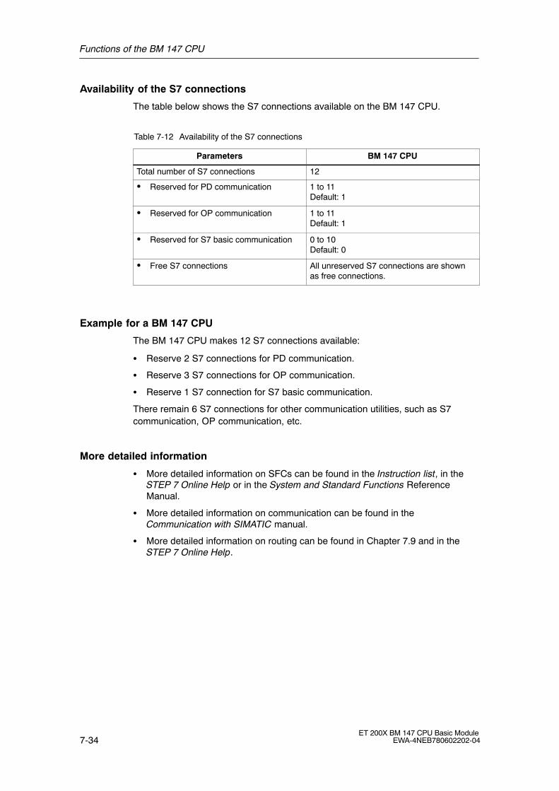
Functions of the BM 147 CPU
7-34ET 200X BM 147 CPU Basic Module
EWA-4NEB780602202-04
Availability of the S7 connections
The table below shows the S7 connections available on the BM 147 CPU.
Table 7-12 Availability of the S7 connections
Parameters BM 147 CPU
Total number of S7 connections 12
� Reserved for PD communication 1 to 11Default: 1
� Reserved for OP communication 1 to 11Default: 1
� Reserved for S7 basic communication 0 to 10Default: 0
� Free S7 connections All unreserved S7 connections are shownas free connections.
Example for a BM 147 CPU
The BM 147 CPU makes 12 S7 connections available:
� Reserve 2 S7 connections for PD communication.
� Reserve 3 S7 connections for OP communication.
� Reserve 1 S7 connection for S7 basic communication.
There remain 6 S7 connections for other communication utilities, such as S7communication, OP communication, etc.
More detailed information
� More detailed information on SFCs can be found in the Instruction list, in theSTEP 7 Online Help or in the System and Standard Functions ReferenceManual.
� More detailed information on communication can be found in theCommunication with SIMATIC manual.
� More detailed information on routing can be found in Chapter 7.9 and in theSTEP 7 Online Help.
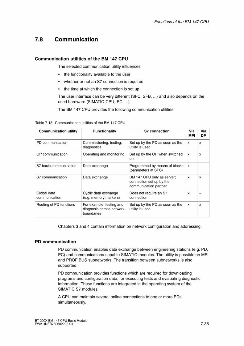
Functions of the BM 147 CPU
7-35ET 200X BM 147 CPU Basic ModuleEWA-4NEB780602202-04
7.8 Communication
Communication utilities of the BM 147 CPU
The selected communication utility influences
� the functionality available to the user
� whether or not an S7 connection is required
� the time at which the connection is set up
The user interface can be very different (SFC, SFB, ...) and also depends on theused hardware (SIMATIC-CPU, PC, ...).
The BM 147 CPU provides the following communication utilities:
Table 7-13 Communication utilities of the BM 147 CPU
Communication utility Functionality S7 connection ViaMPI
ViaDP
PD communication Commissioning, testing,diagnostics
Set up by the PD as soon as theutility is used
x x
OP communication Operating and monitoring Set up by the OP when switchedon
x x
S7 basic communication Data exchange Programmed by means of blocks(parameters at SFC)
x �
S7 communication Data exchange BM 147 CPU only as server;connection set up by thecommunication partner
x x
Global datacommunication
Cyclic data exchange(e.g. memory markers)
Does not require an S7connection
x �
Routing of PD functions For example, testing anddiagnosis across networkboundaries
Set up by the PD as soon as theutility is used
x x
Chapters 3 and 4 contain information on network configuration and addressing.
PD communication
PD communication enables data exchange between engineering stations (e.g. PD,PC) and communications-capable SIMATIC modules. The utility is possible on MPIand PROFIBUS subnetworks. The transition between subnetworks is alsosupported.
PD communication provides functions which are required for downloadingprograms and configuration data, for executing tests and evaluating diagnosticinformation. These functions are integrated in the operating system of theSIMATIC S7 modules.
A CPU can maintain several online connections to one or more PDssimultaneously.

Functions of the BM 147 CPU
7-36ET 200X BM 147 CPU Basic Module
EWA-4NEB780602202-04
OP communication
OP communication enables data exchange between operator stations (e.g. OP,TP) and communications-capable SIMATIC modules. The utility is possible on MPIand PROFIBUS subnetworks.
OP communication provides functions which are required for operation andmonitoring. These functions are integrated in the operating system of theSIMATIC S7 modules.
A CPU can maintain several connections to one or more OPs simultaneously.
S7 basic communication
S7 basic communication enables data exchange between S7-CPUs andcommunications-capable SIMATIC modules within an S7 station (acknowledgeddata exchange). Data is exchanged by means of non-configured S7 connections.The utility is possible on the MPI subnetwork or in the station of function modules(FM).
S7 basic communication provides functions which are required for data exchange.These functions are integrated in the operating system of the BM 147 CPU.
The user can use the utility via the �System Function� user interface (SFC).
S7 communication
BM 147 CPU can only be a server in S7 communication. The connection is alwaysset up by the communication partner. The utility is possible on MPI andPROFIBUS subnetworks.
The utilities are processed by the operating system without an explicit userinterface.

Functions of the BM 147 CPU
7-37ET 200X BM 147 CPU Basic ModuleEWA-4NEB780602202-04
Global data communication
Global data communication enables the cyclic exchange of global data (e.g. I, O,M) between SIMATIC S7-CPUs (unacknowledged data exchange). The data issent to all CPUs in the MPI subnetwork simultaneously by the CPU. This functionis integrated in the operating system of the BM 147 CPU.
Transmit and receive conditions
You should observe the following conditions for communication in GD circles:
� The following must apply for the sender of a GD packet:Scan rateSender x Cycle timeSender � 60 ms
� The following must apply for the recipient of a GD packet:Scan rateRecipient x Cycle timeRecipient< Scan rateSender x Cycle timeSender
A GD packet could be lost if you do not observe these conditions. Reasons for thisare:
� the performance of the �smallest� CPU in the GD circle
� global data is sent and received asynchronously by the sender and recipient
If in STEP 7 you set: �Send After Each CPU Cycle� and the CPU has a short CPUcycle (< 60 ms), the operating system could then overwrite a GD packet on theCPU which has not yet been sent. The loss of global data is indicated in the statusfield of the GD circle, provided that you have configured this option with STEP 7.
Scan rate
The scan rate indicates how many cycles the GD communication is divided into.You can set the scan rate when configuring the global data communication inSTEP 7. If, for example, you select a scan rate of 7, global data communicationonly occurs every 7 cycles. This relieves the load on the CPU.
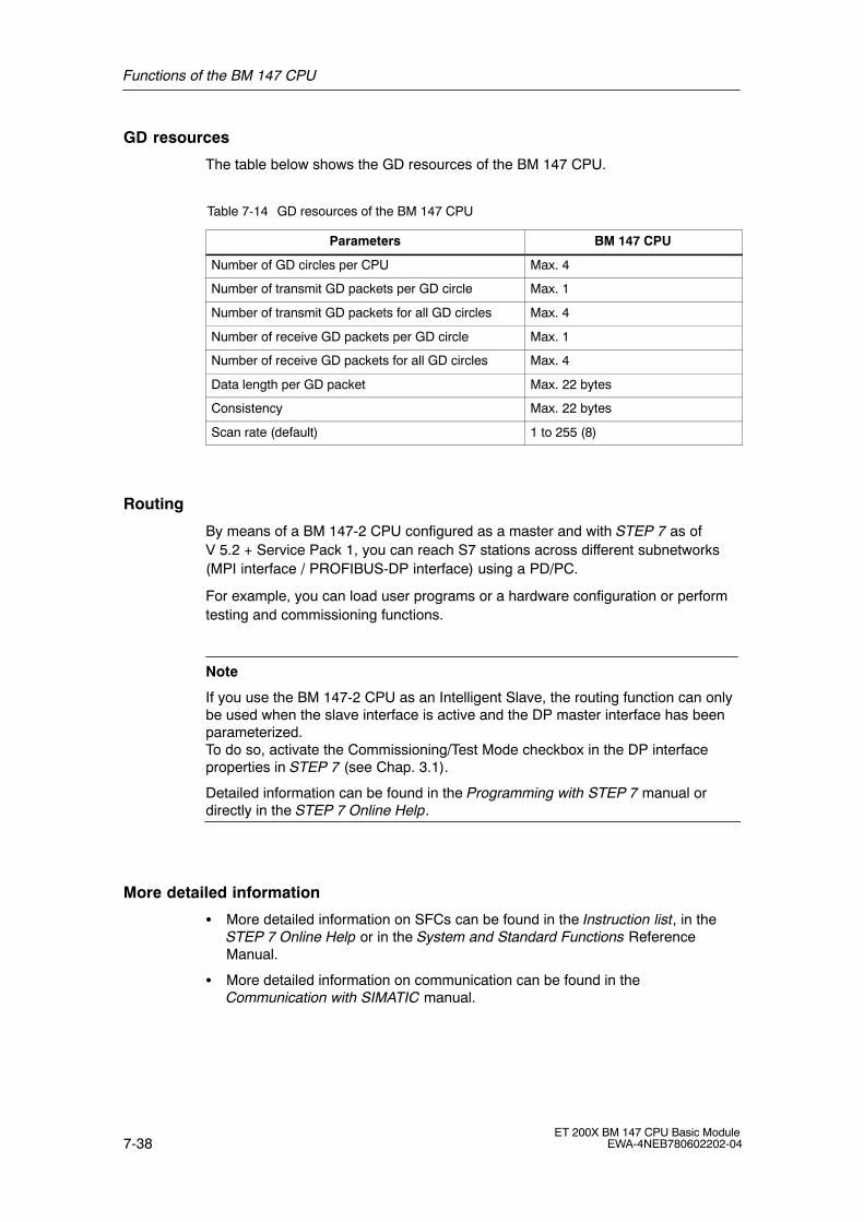
Functions of the BM 147 CPU
7-38ET 200X BM 147 CPU Basic Module
EWA-4NEB780602202-04
GD resources
The table below shows the GD resources of the BM 147 CPU.
Table 7-14 GD resources of the BM 147 CPU
Parameters BM 147 CPU
Number of GD circles per CPU Max. 4
Number of transmit GD packets per GD circle Max. 1
Number of transmit GD packets for all GD circles Max. 4
Number of receive GD packets per GD circle Max. 1
Number of receive GD packets for all GD circles Max. 4
Data length per GD packet Max. 22 bytes
Consistency Max. 22 bytes
Scan rate (default) 1 to 255 (8)
Routing
By means of a BM 147-2 CPU configured as a master and with STEP 7 as ofV 5.2 + Service Pack 1, you can reach S7 stations across different subnetworks(MPI interface / PROFIBUS-DP interface) using a PD/PC.
For example, you can load user programs or a hardware configuration or performtesting and commissioning functions.
Note
If you use the BM 147-2 CPU as an Intelligent Slave, the routing function can onlybe used when the slave interface is active and the DP master interface has beenparameterized.To do so, activate the Commissioning/Test Mode checkbox in the DP interfaceproperties in STEP 7 (see Chap. 3.1).
Detailed information can be found in the Programming with STEP 7 manual ordirectly in the STEP 7 Online Help.
More detailed information
� More detailed information on SFCs can be found in the Instruction list, in theSTEP 7 Online Help or in the System and Standard Functions ReferenceManual.
� More detailed information on communication can be found in theCommunication with SIMATIC manual.

Functions of the BM 147 CPU
7-39ET 200X BM 147 CPU Basic ModuleEWA-4NEB780602202-04
7.9 Routing
Access from a PD/PC to stations in another subnetwork
As of STEP 7 V5.2 + Service Pack 1, you can reach S7 stations acrosssubnetwork boundaries with the PD/PC, for example to load user programs or ahardware configuration or to perform testing and diagnosis functions.
The routing function lets you connect a PD anywhere in the network andestablish a connection to any station that can be reached via the gateways.
The BM 147-2 CPU makes available 4 connections for routing PD functions. Theseconnections are additional to the S7 connections.
Note
If you use the BM 147-2 CPU as an Intelligent Slave, the routing function can onlybe used when the slave interface is active and the DP master interface has beenparameterized.To do so, activate the Commissioning/Test Mode checkbox in the DP interfaceproperties in STEP 7 (see Chap. 3.1).
Detailed information can be found in the Programming with STEP 7 manual ordirectly in the STEP 7 Online Help.

Functions of the BM 147 CPU
7-40ET 200X BM 147 CPU Basic Module
EWA-4NEB780602202-04
Gateway
The gateway from one subnetwork to one or more other subnetworks lies in aSIMATIC station that has interfaces to the respective subnetworks. Thus, in thediagram below, the CPU 31xC-2 DP acts as a router between subnetwork 1 andsubnetwork 2.
Programming device
Subnetwork 1 (e.g. MPInetwork)
S7 statione.g. CPU 31xC-2 DP
DP master
S7 stationET 200XDP slave
Subnetwork 2 (e.g.PROFIBUS-DP
network)
Figure 7-8 Routing gateway
Prerequisites
� The modules of the station are �capable of routing� (CPUs or CPs).
� The network configuration does not extend beyond the project boundaries.
� The modules have loaded in them the configuration information that containsthe current �knowledge� on the entire network configuration of the project.
Reason: All modules that participate in the gateway must contain information onwhich subnetworks can be reached along which routes (= routing information).
� The PD/PC with which you wish to establish a connection via a gateway mustbe assigned in the network configuration to the network to which it is actuallyphysically connected.
� The CPU must be configured as a master.
� If the CPU is configured as a slave, the Commissioning/Test Mode functionalitymust be activated in the DP interface properties for the DP slave in STEP 7.
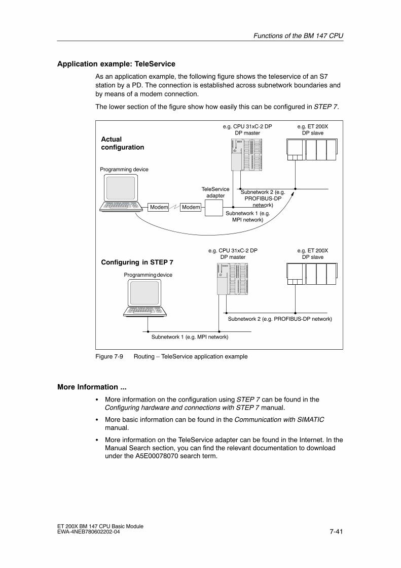
Functions of the BM 147 CPU
7-41ET 200X BM 147 CPU Basic ModuleEWA-4NEB780602202-04
Application example: TeleService
As an application example, the following figure shows the teleservice of an S7station by a PD. The connection is established across subnetwork boundaries andby means of a modem connection.
The lower section of the figure show how easily this can be configured in STEP 7.
Subnetwork 1 (e.g. MPI network)
Subnetwork 2 (e.g. PROFIBUS-DP network)
e.g. CPU 31xC-2 DPDP master
e.g. ET 200XDP slave
Actualconfiguration
Configuring in STEP 7
Programming device
Modem Modem
TeleServiceadapter
e.g. CPU 31xC-2 DPDP master
e.g. ET 200XDP slave
Programming device
Subnetwork 1 (e.g.MPI network)
Subnetwork 2 (e.g.PROFIBUS-DP
network)
Figure 7-9 Routing � TeleService application example
More Information ...
� More information on the configuration using STEP 7 can be found in theConfiguring hardware and connections with STEP 7 manual.
� More basic information can be found in the Communication with SIMATICmanual.
� More information on the TeleService adapter can be found in the Internet. In theManual Search section, you can find the relevant documentation to downloadunder the A5E00078070 search term.

Functions of the BM 147 CPU
7-42ET 200X BM 147 CPU Basic Module
EWA-4NEB780602202-04
7.10 Data consistency
A data area is said to be consistent if it can be read/written by the operatingsystem as a single block. The data that is transmitted together between devicesshould stem from one processing cycle and thus should form a unit, i.e. beconsistent.
If there is a programmed communication function in the user program, for exampleX-SEND/ X-RCV, that accesses shared data, the access to this data area itself canbe coordinated using the �BUSY� parameter.
For PUT/GET functions
For S7 communication functions, such as PUT/GET and read/write via OPcommunication, that do not require a block in the user program of the CPU (asserver), the size of the data consistency must be taken into account duringprogramming.
The PUT/GET functions of the S7 communication or reading/writing of variablesvia the OP communication are processed in the cycle checking point of the CPU.
To ensure a defined process alarm reaction time, the communication variables areconsistently copied in blocks of a maximum of 64 bytes in the cycle checkpoint ofthe operating system into and out of the user memory or memories. Dataconsistency is not guaranteed for any large data areas.
If a defined data consistency is required, the communication variables in the userprogram of the CPU may not exceed 64 bytes in size.
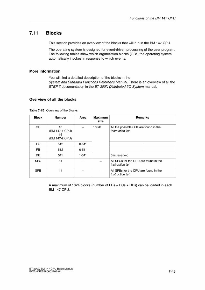
Functions of the BM 147 CPU
7-43ET 200X BM 147 CPU Basic ModuleEWA-4NEB780602202-04
7.11 Blocks
This section provides an overview of the blocks that will run in the BM 147 CPU.
The operating system is designed for event-driven processing of the user program.The following tables show which organization blocks (OBs) the operating systemautomatically invokes in response to which events.
More information
You will find a detailed description of the blocks in the System and Standard Functions Reference Manual. There is an overview of all theSTEP 7 documentation in the ET 200X Distributed I/O System manual.
Overview of all the blocks
Table 7-15 Overview of the Blocks
Block Number Area Maximumsize
Remarks
OB 13(BM 147-1 CPU)
16(BM 147-2 CPU)
� 16 kB All the possible OBs are found in theInstruction list.
FC 512 0-511 �
FB 512 0-511 �
DB 511 1-511 0 is reserved
SFC 61 � � All SFCs for the CPU are found in theInstruction list.
SFB 11 � � All SFBs for the CPU are found in theInstruction list.
A maximum of 1024 blocks (number of FBs + FCs + DBs) can be loaded in eachBM 147 CPU.
Functions of the BM 147 CPU
7-44ET 200X BM 147 CPU Basic Module
EWA-4NEB780602202-04
SFC 55 �WR_PARM�, SFC 56 �WR_DPARM�, SFC 57 �PARM_MOD�, SFC 58 �WR_REC�
The use of SFCs 55 to 58 in conjunction with your BM 147 CPU is notrecommended owing to the static module parameters.
If you do use SFCs 55 to 58 in conjunction with your BM 147 CPU, theBM 147 CPU could malfunction.
Points to note about OB 122
Note
Note the following about OB 122:
The CPU enters the value �0� in the following temporary variables of the variabledeclaration table in the local data of the OB:
� Byte No. 3: OB122_BLK_TYPE (type of block in which the error occurred)
� Byte No. 8 and 9: OB122_BLK_NUM (number of block in which the error occurred)
� Byte No. 10 and 11: OB122_PRG_ADDR (address of block in which the error occurred)

Functions of the BM 147 CPU
7-45ET 200X BM 147 CPU Basic ModuleEWA-4NEB780602202-04
7.12 Parameters
Parameterizable features
The properties and responses of the BM 147 CPU can be parameterized. Youcarry out this parameterization on different tabs in STEP 7.
Which parameters can be set for the BM 147 CPU?
The following table contains all the parameter blocks for the BM 147 CPU. Theparameters are explained in the STEP 7 Online Help.
Table 7-16 Parameter blocks, settable parameters and their ranges for the BM 147 CPU
Parameterblocks
Settable parameters Range
Startup Startup at preset configuration not equal toactual configuration
Yes/no
Startup after power on Warm restart
Monitoring time for:
� �Finished� message by means of modules(100 ms)
� Transfer of the parameters to modules(100 ms)
1 to 650
1 to 10000
Diagnostics/Clock Report cause of STOP Yes/no
Synchronization in PLC
� Type
� Interval
None/as master
1 s/10 s/1 min/10 min/1 h/12 h/24 h
Synchronization to MPI
� Type
� Interval
None/as master/as slave
1 s/10 s/1 min/10 min/1 h/12 h/24 h
Correction factor �10000 to +10000
Retentivity Number of memory bytes starting with MB 0 0 to 255
Number of S7 timers starting with T 0 0 to 255
Number of S7 counters starting with C 0 0 to 255
Time-of-dayinterrupts
OB 10 activation Yes/no
OB 10 execution � None
� Once
� Every minute
� Hourly
� Daily
� Weekly
� Monthly
� Last day of the month
� Annually
Start date for the OB 10 Year-month-day

Functions of the BM 147 CPU
7-46ET 200X BM 147 CPU Basic Module
EWA-4NEB780602202-04
Table 7-16 Parameter blocks, settable parameters and their ranges for the BM 147 CPU
Parameterblocks
RangeSettable parameters
Start time for the OB 10 Hours:minutes
Cyclic interrupts Periodicity of the OB 35 (ms) 1 to 60000
Cycle/clockmemory
Scan cycle monitoring time (ms) 1 to 6000
Cycle load from communication (%) 10 to 50
OB85 call at I/O access error � For each access
� For incoming and outgoingerrors
� No call
Clock memory Yes/no
Memory byte 0 to 255
Protection Level of protection � 1: Key switch
� 2: Write protection
� 3: Write/readprotection
Mode � Process mode:permissible cycle increase (ms)from 3 to 65535
� Test mode
Communication PD communication 1 to 11
OP communication 1 to 11
S7 basic communication 0 to 10
When does the CPU �accept� the parameters?
The CPU accepts the parameters (configuration data) you have set:
� After POWER ON or a memory reset of the inserted memory module
� After the configuration data has been transferred without errors to the CPUonline in STOP mode

8-1ET 200X BM 147 CPU Basic ModuleEWA-4NEB780602202-04
Cycle and Response Times
Introduction
In this chapter you will learn what the cycle time and response time of the ET 200Xwith the BM 147 CPU consist of.
You can use the PD to read out the cycle time of your user program (see theSTEP 7 user manual).
The response time is more important for the process. In this chapter we will showyou in detail how to calculate the response time.
Chapter overview
In Section Contents Page
8.1 Cycle time 8-2
8.2 Response time 8-5
8.3 Interrupt response time 8-8
8.4 Calculation examples 8-9
Execution times
� For the STEP 7 instructions that can be processed by the CPUs can be foundin the Instruction list.
� For the SFCs/SFBs integrated in the CPUs can be found in the Instruction list.
8

Cycle and Response Times
8-2ET 200X BM 147 CPU Basic Module
EWA-4NEB780602202-04
8.1 Cycle time
Cycle time � a definition
The cycle time is the time that the operating system requires to process a programcycle � i.e. an OB 1 cycle � as well as all the program sections and systemactivities interrupting this cycle.
This time is monitored.
Components of the cycle time
Factors Remarks
Operating system execution time See Table 8-1
Process image transfer time (PII andPIQ) See Table 8-2
User program execution time Is calculated from the execution times of theindividual instructions and a CPU-specific factor(for BM 147 CPU: 1.1).
Loading through interrupts See Table 8-3
The following figure shows the components that make up the cycle time:
PII
Operatingsystem
Cyclic userprogram (OB 1)
PIQ
Interrupts
Operatingsystem
Acyclic userprogram (e.g. OB40/82)
Figure 8-1 Component parts of the cycle time

Cycle and Response Times
8-3ET 200X BM 147 CPU Basic ModuleEWA-4NEB780602202-04
Extending the cycle time
Note that the cycle time of a user program is extended by the following:
� Time-controlled interrupt handling
� Process interrupt handling (see also Section 8.3)
� Diagnostics and error handling (see also Section 8.3)
Operating system processing time
The operating system execution time for the BM 147 CPU is found in Table 8-1.
The specified time does not include the execution of:
� Testing and commissioning functions such as status/control of variables orblock status
� Functions: Load block, delete block, compress block
� Communication
� Writing and reading the MMC with SFC 82 to 84
Table 8-1 Operating system processing time in the scan cycle checkpoint
Sequence BM 147 CPU
Operating system processing time 500 �s
Process image transfer time
The table below contains the CPU times for process image updating (processimage transfer time). The specified times can be longer as a result of interruptsthat occur or by communication involving the CPU component of the BM 147 CPU.
(Process image = PI)
The CPU time for process image updating is calculated as follows:
K + A + D = Process image transfer time, in which K, A and D equal the following:
Table 8-2 Process image updating
Designation Times in BM 147 CPU
K Base load 100 �s
Q Bytes in the PI for the ET 200X I/O 35 �s per byte
D Per word in the DP area 1 �s

Cycle and Response Times
8-4ET 200X BM 147 CPU Basic Module
EWA-4NEB780602202-04
Dependency of the user program scanning time
Simultaneously to actually executing the user program, the operating system ofyour CPU performs additional processes (e.g. timer management of core operatingsystem). These processes prolong the execution time of the user program.
For the BM 147 CPU, multiply the execution time of your user program by a factorof 1.1.
Delay of the inputs and outputs
You have to take into account the following delay times, depending on theexpansion module:
� For digital inputs: The input delay time
� For digital outputs: Negligible delay times
� For analog inputs: Cycle time of the analog input
� For analog outputs: Response time of the analog output
Extending the cycle by nesting interrupts
Table 8-3 shows typical extensions of the cycle time through nesting of aninterrupt. The program runtime at the interrupt level must be added to these. Ifseveral interrupts are nested, the corresponding times need to be added.
Table 8-3 Extending the cycle by nesting interrupts
Interrupts BM 147 CPU
Process interrupt 500 µs
Diagnostic interrupt 600 µs
Time-of-day interrupt 400 µs
Delay interrupt 300 µs
Watchdog interrupt 150 µs
Status interrupt/update interrupt/manufacturer-specificinterrupt 1)
600 µs
Programming/access error/runtime system error 400 µs
1) For BM 147-2 CPU only

Cycle and Response Times
8-5ET 200X BM 147 CPU Basic ModuleEWA-4NEB780602202-04
8.2 Response time
Response time for ET 200X with BM 147 CPU
The response time is the time from the detection of an input signal at the ET 200Xwith the BM 147 CPU to the modification of an associated output signal via theinputs and outputs of the expansion modules.
Factors
The response time depends on the cycle time and the following factors:
Factors Remarks
Delay of the inputs and outputs You can find the delay times in the technicalspecifications of the expansion modules inthe ET 200X Distributed I/O Device manual.
Range of fluctuation
The actual response time lies between a shortest and a longest response time.You must always reckon on the longest response time when configuring yoursystem.
The shortest and longest response times are considered below to let you get anidea of the width of fluctuation of the response time.

Cycle and Response Times
8-6ET 200X BM 147 CPU Basic Module
EWA-4NEB780602202-04
Shortest response time
The following figure shows you the conditions under which the shortest responsetime is obtained.
Operatingsystem
Userprogram
PIIThe status of the observed input changes immediatelybefore reading in the PII. The change in the inputsignal is therefore taken account of in the PII.
PIQ
The change in the input signal is processedby the user program here.
The response of the user program to the input signalchange is passed on to the outputs here.
Res
pons
e tim
eDelay of the inputs
Delay of the outputs
Figure 8-2 Shortest response time
Calculation
The (shortest) response time consists of the following:
� 1 � process image transfer time for the inputs +
� 1 � operating system processing time +
� 1 � program scanning time +
� 1 � process image transfer time for outputs +
� Delay of the inputs and outputs
This corresponds to the sum of the cycle time and the delay of the inputs andoutputs.

Cycle and Response Times
8-7ET 200X BM 147 CPU Basic ModuleEWA-4NEB780602202-04
Longest response time
The following figure shows what the longest response time consists of.
Operatingsystem
Userprogram
PIIWhile the PII is being read in, the status ofthe observed input changes. The change inthe input signal is no longer taken intoaccount in the PII.
PIQ
The change in the input signal is takenaccount of in the PII here.
The change in the input signal is processedby the user program here.
The response of the user program to the inputsignal change is passed on to the outputshere.
Res
pons
e tim
eDelay of the inputs +
2 � DP cycle time at the PROFIBUS-DP
Delay of the outputs +2 � DP cycle time at the PROFIBUS-DP
Operatingsystem
Userprogram
PII
PIQ
Figure 8-3 Longest response time
Calculation
The (longest) response time consists of the following:
� 2 � process image transfer time for the inputs +
� 2 � process image transfer time for the outputs +
� 2 � operating system processing time +
� 2 � program scanning time +
� 4 � run time of the DP slave frame (incl. processing in the DP master) +
� Delay of the inputs and outputs
This corresponds to the sum of 2x cycle time and delay of the inputs and outputsplus 4x DP cycle time.

Cycle and Response Times
8-8ET 200X BM 147 CPU Basic Module
EWA-4NEB780602202-04
8.3 Interrupt response time
Interrupt response time � a definition
The interrupt response time is the time from the first occurrence of an interruptsignal to the call of the first instruction in the interrupt OB of the BM 147 CPU.
The following generally applies: Interrupts of higher priority have precedence. Thismeans that the program processing time of the higher-priority interrupt OB and ofthe not yet processed interrupt OBs of the same priority which occurred previously(queue) is added to the interrupt response time.
Interrupt response times
Table 8-4 Interrupt response times of the BM 147 CPU (without communication)
Interrupt response times (without communication)for...
Duration
min. max.
Process interrupt 0.4 ms 0.7 ms
Diagnostics interrupt 0.4 ms 1.0 ms
Process interrupt handling
Process interrupt handling begins when the process interrupt OB 40 is called. Higher-priority interrupts cause the process interrupt handling routine to beinterrupted. Direct accesses to the I/Os are made at the execution time of theinstruction. After process interrupt handling has been completed, either cyclicprogram scanning is continued or additional interrupt OBs of the same priority or alower priority are called and processed.

Cycle and Response Times
8-9ET 200X BM 147 CPU Basic ModuleEWA-4NEB780602202-04
8.4 Calculation examples
8.4.1 Calculation examples for the cycle time and response time
Sample configuration
You have configured an ET 200X with the following modules:
� 1 BM 147 CPU basic module
� 2 EM 141 DI 8�DC 24 V expansion modules (4 bytes each in the PI)
� 2 EM 142 DO 4�DC 24 V/0.5A expansion modules (4 bytes each in the PI)
The user program has a runtime of 1.5 ms. Communication takes place only to theDP master.
Component parts of the cycle time
As a reminder: The cycle time consists of the following
� Operating system processing time +
� Process image transfer time +
� User program processing time +
� Loading through interrupts
Calculation
In this example, the cycle time is obtained from the following times:
� Operating system processing time in the scan cycle checkpoint:
Approx. 0.5 ms
� Process image transfer time
Process image of the inputs: 100 �s + 8 bytes�35 �s = approx. 0.38 ms
Process image of the outputs: 100 �s + 8 bytes�35 �s = approx. 0.38 ms
� User program processing time:
Approx. 1.5 ms � factor specific to basic module 1.1 = approx. 1.65 ms
Cycle time = 0.5 ms + 0.38 ms + 0.38 ms + 1.65 ms = approx. 2.9 ms.

Cycle and Response Times
8-10ET 200X BM 147 CPU Basic Module
EWA-4NEB780602202-04
Components of the response time
As a reminder: The longest response time is the sum of
� 2 � process image transfer time for the inputs +
� 2 � process image transfer time for the outputs +
� 2 � operating system processing time +
� 2 � program scanning time +
� Delay times of inputs and outputs
Calculation
Tip: Simple calculation: calculated cycle time � 2 + delay times of inputs andoutputs.
The following therefore applies to the sample configuration (where the delay timeof the outputs can be disregarded):
Response time = 2.9 ms � 2 + 8 � 4.8 ms = approx. 44.2 ms
8.4.2 Calculation example for the interrupt response time
Sample configuration
You have configured an ET 200X with the following modules:
� 1 BM 147 CPU basic module
� An EM 141 DI 8�DC 24 V expansion module
When you set the parameters for the BM 147 CPU, you only released the processinterrupt. You decided not to use diagnostics or error handling. The expansionmodule has an input delay of 4.8 ms. No action is necessary at the cyclecheckpoint. No communication takes place.
Calculation
The process interrupt response time in this example is obtained from the followingtimes:
� Process interrupt response time of the BM 147 CPU: approx. 0.7 ms
� Internal interrupt preparation time: 0.25 ms
� Input delay: 4.8 ms
The process interrupt response time is calculated from the sum of times:
Process interrupt response time = 0.7 ms + 0.25 ms + 4.8 ms = approx. 5.75 ms.
This process interrupt response time elapses from the time a signal is applied tothe digital input until the first instruction in OB 40.

9-1ET 200X BM 147 CPU Basic ModuleEWA-4NEB780602202-04
Technical Specifications
In this chapter
In this chapter you will find:
� The technical data of basic module BM 147 CPU
9
Technical Specifications
9-2ET 200X BM 147 CPU Basic Module
EWA-4NEB780602202-04
9.1 Technical specifications of the BM 147 CPU
Order numbers
BM 147-1 CPU basic module: 6ES7 147-1AA10-0XB0
BM 147-2 CPU basic module: 6ES7 147-2AA00-0XB0
SIMATIC micro memory card (MMC): 6ES7 953-8Lxx0-0AA0(see Section 7.3)
Features
Basic module BM 147 CPU has the following features:
� Intelligent slave with RS 485 interface to the PROFIBUS-DP
� Stand-alone operation (MPI) possible
� 48 kByte working memory, non-expandable, retentive with inserted MMC
� Plug-in load memory on the MMC, up to 8 MBytes
� Powerfail-proof storage of the user program and configuration via MMC
� Programmable with STEP 7, V5.2 or higher + Service Pack 1
� Service-free
� No integrated I/O devices
� Maximum configuration of the local I/Os: 7 expansion modules of the ET 200X spectrum
In addition to the features listed above, basic module BM 147-2 CPU also offersDP master functionality. Up to 32 DP slaves can be connected to the DP masterinterface.
General technical specifications
The BM 147 CPU meets the general technical specifications of the ET 200Xdistributed I/O device. You will find these standards and test specifications in thechapter entitled �General Technical Specifications� in the ET 200X Distributed I/ODevice manual.
Use in direct sunlight is not permissible (due to excessive heating of the device).
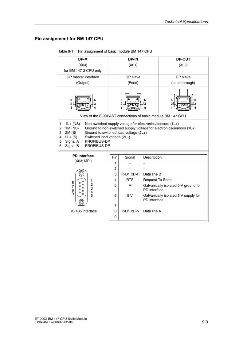
Technical Specifications
9-3ET 200X BM 147 CPU Basic ModuleEWA-4NEB780602202-04
Pin assignment for BM 147 CPU
Table 9-1 Pin assignment of basic module BM 147 CPU
DP-M
(X04)
� for BM 147-2 CPU only �
DP-IN
(X01)
DP-OUT
(X02)
DP master interface
(Output)
DP slave
(Feed)
DP slave
(Loop through)
521
634
521
634
521
634
View of the ECOFAST connections of basic module BM 147 CPU
1 1L+ (NS) Non-switched supply voltage for electronics/sensors (1L+)2 1M (NS) Ground to non-switched supply voltage for electronics/sensors (1L+)3 2M (S) Ground to switched load voltage (2L+)4 2L+ (S) Switched load voltage (2L+)5 Signal A PROFIBUS-DP6 Signal B PROFIBUS-DP
12345
6789
PD interface
RS 485 interface
(X03; MPI)Pin
1
2
3
4
5
6
7
8
9
Signal
�
�
RxD/TxD-P
RTS
M
5 V
�
RxD/TxD-N
�
Description
�
�
Data line B
Request To Send
Galvanically isolated 5 V ground for PD interface
Galvanically isolated 5 V supply for PD interface
�
Data line A
�

Technical Specifications
9-4ET 200X BM 147 CPU Basic Module
EWA-4NEB780602202-04
Basic circuit diagram for the BM 147 CPU
Internal powersupply
Q
PROFIBUS-DP master(RS 485)
Galvanicisolation
ON
CPU(�P, RAM)
Mode selectorMRES
RUNSTOP
MMC
Ele
ctro
nics
BF-S
SF
RUN
STOP
B
Q
PROFIBUS-DP connec-tion (RS 485)
Galvanicisolation
B
Backplane businterfacemodule
FRCE
BF-M
24 VDCLoad voltagedisplay
*) For BM 147-2 CPU only
*)
*)X04
QB
Q
B
X01
X02
X03
Figure 9-1 Block diagram BM 147 CPU
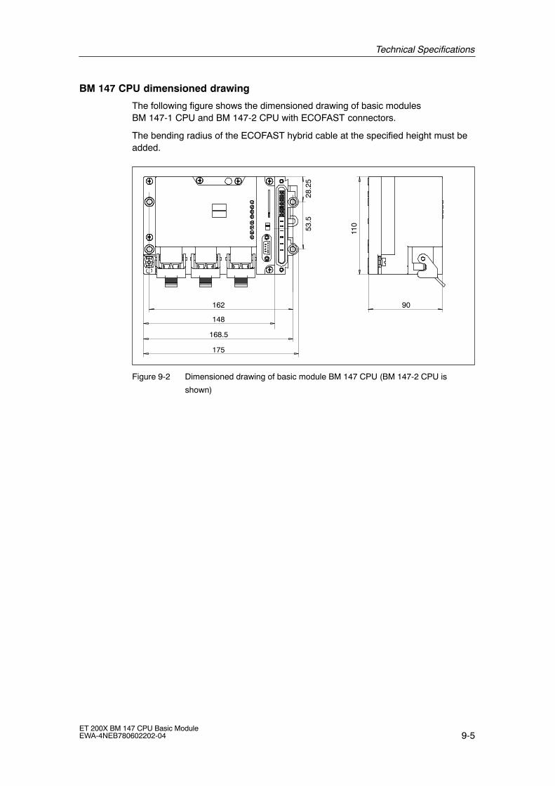
Technical Specifications
9-5ET 200X BM 147 CPU Basic ModuleEWA-4NEB780602202-04
BM 147 CPU dimensioned drawing
The following figure shows the dimensioned drawing of basic modulesBM 147-1 CPU and BM 147-2 CPU with ECOFAST connectors.
The bending radius of the ECOFAST hybrid cable at the specified height must beadded.
175
168.5
148
162 9053
.528
.25
110
Figure 9-2 Dimensioned drawing of basic module BM 147 CPU (BM 147-2 CPU is
shown)
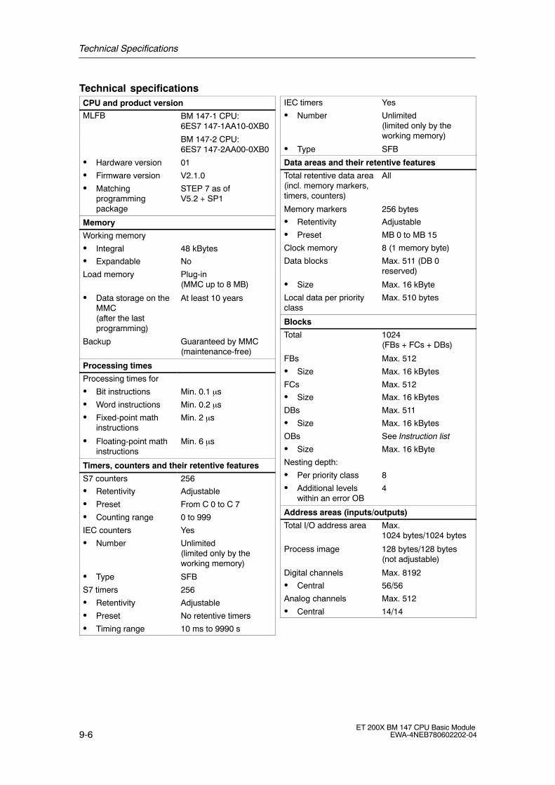
Technical Specifications
9-6ET 200X BM 147 CPU Basic Module
EWA-4NEB780602202-04
Technical specificationsCPU and product version
MLFB BM 147-1 CPU:6ES7 147-1AA10-0XB0
BM 147-2 CPU:6ES7 147-2AA00-0XB0
� Hardware version 01
� Firmware version V2.1.0
� Matchingprogrammingpackage
STEP 7 as ofV5.2 + SP1
Memory
Working memory
� Integral 48 kBytes
� Expandable No
Load memory Plug-in(MMC up to 8 MB)
� Data storage on theMMC(after the lastprogramming)
At least 10 years
Backup Guaranteed by MMC(maintenance-free)
Processing times
Processing times for
� Bit instructions Min. 0.1 µs
� Word instructions Min. 0.2 µs
� Fixed-point mathinstructions
Min. 2 µs
� Floating-point mathinstructions
Min. 6 µs
Timers, counters and their retentive features
S7 counters 256
� Retentivity Adjustable
� Preset From C 0 to C 7
� Counting range 0 to 999
IEC counters Yes
� Number Unlimited (limited only by theworking memory)
� Type SFB
S7 timers 256
� Retentivity Adjustable
� Preset No retentive timers
� Timing range 10 ms to 9990 s
IEC timers Yes
� Number Unlimited (limited only by theworking memory)
� Type SFB
Data areas and their retentive features
Total retentive data area(incl. memory markers,timers, counters)
All
Memory markers 256 bytes
� Retentivity Adjustable
� Preset MB 0 to MB 15
Clock memory 8 (1 memory byte)
Data blocks Max. 511 (DB 0reserved)
� Size Max. 16 kByte
Local data per priorityclass
Max. 510 bytes
Blocks
Total 1024(FBs + FCs + DBs)
FBs Max. 512
� Size Max. 16 kBytes
FCs Max. 512
� Size Max. 16 kBytes
DBs Max. 511
� Size Max. 16 kBytes
OBs See Instruction list
� Size Max. 16 kByte
Nesting depth:
� Per priority class 8
� Additional levelswithin an error OB
4
Address areas (inputs/outputs)
Total I/O address area Max.1024 bytes/1024 bytes
Process image 128 bytes/128 bytes(not adjustable)
Digital channels Max. 8192
� Central 56/56
Analog channels Max. 512
� Central 14/14

Technical Specifications
9-7ET 200X BM 147 CPU Basic ModuleEWA-4NEB780602202-04
Time
Clock Hardware clock
� Buffered Yes
� Backup time Typ. 6 weeks (atambient temperature of40 °C)
� Accuracy Deviation per day�10 s
Run-time meter 1
� Number 0
� Range 0 to 231 hours(when using theSFC 101)
� Selectivity 1 hour
� Retentive Yes; must be restartedwith every restart
Time synchronization Yes
� In the PLC Master
� On the MPI Master/slave
S7 message functions
Number of logon-ablestations for signalingfunctions (e.g. OS)
Max. 12
Process diagnosticmessages
ALARM_S,ALARM_SC,ALARM_SQ
� Simultaneouslyactive Alarm_Sblocks
Max. 40
Testing and commissioning functions
Status/modify variables Yes
� Variable Inputs, outputs, memorymarkers, DBs, timers,counters
� Number of variables
� Of which statusvariables
� Of which modifyvariables
Max. 30
Max. 30
Max. 14
Force Yes
� Variable Inputs, outputs
� Number Max. 10
Monitor block Yes
Single sequence Yes
Breakpoint 2
Diagnostic buffer Yes
� Number of inputs Max. 100 (notadjustable)
Communication functions
PD/OP communication Yes
Global datacommunication
Yes
� Number of GDpackets
Max. 4
� Sender Max. 4
� Receiver Max. 4
� Size of GD packets Max. 22 bytes
� Number of whichconsistent
22 bytes
S7 basiccommunication
Yes
� User data per job Max. 76 bytes
� Number of whichconsistent
76 bytes(XSEND/XRCV)
64 bytes(XPUT/XGET) as server
S7 communication Yes (server)
� User data per job Max. 180 bytes
� Number of whichconsistent
64 bytes
S5-compatiblecommunication
No
Standardcommunication
No
Number of connections Max. 12
Used for
� PD communication Max. 11
� Reserved (default)
1
� OP communication Max. 11
� Reserved (default)
1
� S7 basiccommunication
Max. 10
� Reserved (default)
0
Routing Max. 4(for BM 147-2 CPUonly; the slave interfacemust be active)

Technical Specifications
9-8ET 200X BM 147 CPU Basic Module
EWA-4NEB780602202-04
Interface
Slave interface
Type of interface Coexistent, integratedRS 485 interface
Physical system RS 485
Galvanically isolated Yes
Functionality
� MPI Yes
� PROFIBUS-DP DP slave(active/passive)
� Point-to-pointconnection
No
MPI
� Number ofconnections
12
� Utilities:
� PD/OPcommunication
Yes
� Routing(BM 147-2 CPUonly)
Yes
� Global datacommunication
Yes
� S7 basiccommunication
Yes
� S7communication
Yes (only server)
� Transmission rates Max. 12 Mbaud
DP slave
� Number ofconnections
12 (each BM 147 CPU)
� Utilities:
� PD/OPcommunication
Yes
� Routing(BM 147-2 CPUonly)
Yes (only with activeinterface)
� Directcommunication
Yes
� Transmission rates Up to 12 Mbaud
� Automatic transmission ratesearch
Yes (only with passiveinterface)
� Intermediatememory
244 I bytes/244 O bytes
� Address areas 32 with a maximum of32 bytes each *
� DPV1 No
� DDB (DeviceDatabase) file
You can find the currentdevice master file at http://www.ad.siemens.de/csi_e/gsd.
Master interface (BM 147-2 CPU only)
Type of interface Integrated RS 485interface
Physical system RS 485
Galvanically isolated Yes
Functionality
� MPI No
� PROFIBUS-DP DP master
� Point-to-pointconnection
No
DP master
� Number ofconnections
12 (each BM 147 CPU)
� Utilities:
� PD/OPcommunication
Yes
� Routing Yes
� Global datacommunication
No
� S7 basiccommunication
No
� S7communication
Yes (only server)
� Directcommunication
Yes
� Clocksynchronism
Yes
� SYNC/FREEZE Yes
� Activate/deacti-vate DP slaves
Yes
� DPV1 Yes
� Transmission rates Up to 12 Mbaud
� Number of DPslaves per station
32
� Address area Max. 1 kByte I/1 kByte O
� User data per DPslave
Max. 244 I bytes/244 O bytes

Technical Specifications
9-9ET 200X BM 147 CPU Basic ModuleEWA-4NEB780602202-04
Programming
Programming language STEP 7 (LAD, FBD,STL)
Stored instructions See Instruction list
Nesting levels 8
System functions (SFCs) See Instruction list
System function blocks(SFBs)
See Instruction list
User program security Yes
Dimensions and weight
Installation dimensions W�H�D (mm) 175 x 110 x 90
Weight Approx. 700 g
Voltages, currents, potentials
Non-switched supplyvoltage forelectronics/sensors(1L+)
24 VDC
� Permissible range 20.4 to 28.8 V
� Max. permissiblefeed current forsupply voltage (1L+)
Up to 40 °C 10 Ato 55 °C 8 A
� Polarity reversalprotection
No
� Short-circuitprotection
Yes, internal (thermally reversible)No, for looping through
� Voltage failurebuffering
No
Switched load voltage(2L+)
24 VDC
� Permissible range 20.4 to 28.8 V
� Max. permissiblefeed current for loadvoltage (2L+)
Up to 40 °C 10 Ato 55 °C 8 A
� Polarity reversalprotection
No
� Short-circuitprotection
No
Galvanic isolation
� Between the supplyvoltage (1L+) andthe load voltage(2L+)
Yes
� Between the loadvoltage (2L+) and all other circuitcomponents
Yes
� BetweenPROFIBUS-DP andall other circuitcomponents
Yes
� Between thenon-switched supplyvoltage (1L+) and PROFIBUS-DP
Yes
� Between the PROFIBUS-DPslave and PROFIBUS-DPmaster
Yes
Permitted potentialdifference
� Between differentcircuits
75 VDC, 60 VAC
Insulation tested at 500 VDC
Current consumptionfrom the non-switchedsupply voltage (1L+)
� Typ. 85 mA
� Max. 160 mA
Power loss of module Typ. 3 W
* Up to the maximum size of the intermediatememory

Technical Specifications
9-10ET 200X BM 147 CPU Basic Module
EWA-4NEB780602202-04

10-1ET 200X BM 147 CPU Basic ModuleEWA-4NEB780602202-04
Changing from BM 147 CPU(6ES7 147-1AA01-0XB0) to BM 147-1 CPUor BM 147-2 CPU
If you download your existing user program for the BM 147 CPU(6ES7 147-1AA01-0XB0) to a BM 147-1 CPU or BM 147-2 CPU(6ES7 147-xAAx0-0XB0), you may encounter the following problems:
The SFC 56, SFC 57 and SFC 13 may work asynchronously
A number of asynchronous SFCs are always processed or, under certainconditions, already processed following the first call (�quasi-synchronous�) on theBM 147 CPU (6ES7 147-1AA01-0XB0)
These SFC run truly asynchronously on the BM 147-1 CPU or BM 147-2 CPU(6ES7 147-xAAx0-0XB0). The asynchronous processing may continue for severalOB 1 cycles. As a result, a queue within an OB may become a continuous loop.
� SFC 56 �WR_DPARM�; SFC 57 �PARM_MOD�
These SFC always run �quasi-synchronously� on a standalone BM 147 CPU(6ES7 147-1AA01-0XB0).They run asynchronously on standalone BM 147-1 CPU or BM 147-2 CPU(6ES7 147-xAAx0-0XB0) and on distributed BM 147-1 CPU or BM 147-2 CPU.
Note
If you use the SFC 56 �WR_DPARM� or SFC 57 �PARM_MOD�, you shouldalways evaluate the BUSY bit of the SFCs.
10

Changing from BM 147 CPU (6ES7 147-1AA01-0XB0) to BM 147-1 CPU or BM 147-2 CPU
10-2ET 200X BM 147 CPU Basic Module
EWA-4NEB780602202-04
� SFC 13 �DPNRM_DG�
This SFC always runs �quasi-synchronously� when called in OB 82.It generally runs asynchronously on BM 147-1 CPU or BM 147-2 CPU(6ES7 147-xAAx0-0XB0).
Note
In the user program, all that should take place is that the task should be called inthe OB 82. The evaluation of the data, which should take into account the BUSYbits and the acknowledgement in the RET_VAL, should take place in the cyclicprogram.
Tip:With BM 147-1 CPU or BM 147-2 CPU we recommend using the SFB 54 insteadof the SFC 13.
SFC 20 �BLKMOV�
Previously this SFC could also be used to copy data from a non-process-relatedDB.
The SFC 20 no longer has this functionality. The SFC 83 �READ_DBL� must nowbe used for this purpose.
SFC 54 �RD_DPARM�
This SFC is no longer available. The asynchronous SFC 102 �RD_DPARA� mustbe used instead.
SFCs which may give different results
If you only use logical addressing in your user program, you can ignore thefollowing points.
If you use address conversions in the user program (SFC 5 �GADR_LGC�, SFC 49�LGC_GADR�), you must check the slot assignment and logical start addressassignment for DP slaves.
� The diagnostic address of the DP slave is now always assigned to slot 0(station proxy).
� The DP slave is integrated in STEP 7:
The basic module (slot 2) may have its own address(e.g. BM 147-1 CPU or BM 147-2 CPU as Intelligent Slave).

Changing from BM 147 CPU (6ES7 147-1AA01-0XB0) to BM 147-1 CPU or BM 147-2 CPU
10-3ET 200X BM 147 CPU Basic ModuleEWA-4NEB780602202-04
Changed runtimes during program processing
If you have created a user program that is optimized for the execution of certainprocessing times, it is important to note the following when using the BM 147-1CPU or BM 147-2 CPU:
� Program processing in BM 147-1 CPU or BM 147-2 CPU is significantly faster.
� Functions that require MMC access (e. g. system runup, program download inRUN, DP station recovery, etc.), may run slower on the BM 147-1 CPU andBM 147-2 CPU.
Changing the diagnostic addresses of DP slaves
It is important to note that the diagnostic addresses for the slaves may have to bereassigned in some cases since two diagnostic addresses per slave aresometimes required due to adaptation to the DPV1 standard.
� The virtual slot 0 has its own address (diagnostic address of the station proxy).
The module state data for this slot (read out with SFC 51 �RDSYSST�) containsthe identifiers which affect the complete slave/station, e.g. the �Station Faulty�identifier. The station failure and station recovery are also signaled in the OB 86of the master via the diagnostic address of the virtual slot 0.
� Furthermore, slot 2 also has its own address in the case of modules integratedin STEP 7 (e.g. BM 147-1 CPU or BM 147-2 CPU as I-slave). This address isused to signal the change in operating state in the diagnostic interrupt OB 82 ofthe master, e.g. with BM 147-1 CPU or BM 147-2 CPU as I-slave.
Note
Reading out the diagnosis with SFC 13 �DPNRM_DG�:
The diagnostic address originally assigned still functions. Internally, STEP 7assigns slot 0 to this address.
If you use the SFC 51 �RDSYSST� to read out, for example, module stateinformation or rack/station state information, you must also take the changedmeaning of the slots and the additional slot 0 into consideration.

Changing from BM 147 CPU (6ES7 147-1AA01-0XB0) to BM 147-1 CPU or BM 147-2 CPU
10-4ET 200X BM 147 CPU Basic Module
EWA-4NEB780602202-04
Using consistent data areas in the process image with DP slaves
Below is a list of the points to which you must pay attention with communication ina DP master system if you want to transfer I/O areas with the �Total Length�consistency.
� If the address area of consistent data is in the process image, this area isupdated automatically.
� You can also use the SFCs 14 and 15 to read and write consistent data.
� If the address area for consistent data is outside the process image, you mustuse the SFCs 14 and 15 to read and write consistent data.
� It is also possible to address the consistent areas directly (for example, L PIWor T PQW).
You can transfer a maximum of 32 bytes of consistent data.
PD/OP functions
In the BM 147 CPU (6ES7 147-1AA01-0XB0), PD/OP functions at the DP interfacewere only possible at an active interface. In the BM 147-1 CPU and BM 147-2 CPU (6ES7 147-xAAx0-0XB0), thesefunctions are possible at both passive and active interfaces. However, theperformance at the passive interface is noticeably lower.
Routing in BM 147-2 CPU as intelligent slave
If you use the BM 147-2 CPU as an intelligent slave, the routing function can onlybe used when the slave interface is active and the DP master interface has beenparameterized.To do so, activate the Commissioning/Test Mode checkbox in the DP interfaceproperties in STEP 7.
Changing from BM 147 CPU (6ES7 147-1AA01-0XB0) to BM 147-1 CPU or BM 147-2 CPU
10-5ET 200X BM 147 CPU Basic ModuleEWA-4NEB780602202-04
New functionalities of the BM 147-1 CPU and BM 147-2 CPU(6ES7 147-xAAx0-0XB0)
� The node address (PROFIBUS-DP and MPI) no longer has to be set.
� The PROFIBUS-DP connectors are designed in ECOFAST technology (seeChapter 5).
� Coexistent interface MPI/DP (active/passive) (see Chapter 7.5)A PD can be connected directly to the new MPI interface.
� Additional DP master interface for BM 147-2 CPU (see Chapter 7.5)
� New memory concept (see Section 7.4)
� Global data communication (see Section 7.8)
This utility is used to enable the cyclic exchange of global data betweenSIMATIC S7-CPUs (and therefore also the BM 147-1 CPU andBM 147-2 CPU).
� S7 basic communication (see Section 7.8)
This utility is used to enable data exchange between the BM 147-1 CPU orBM 147-2 CPU and communications-capable SIMATIC modules within an S7station. The SFCs 65 to 74 are provided to support this.
� MMC up to 8 MBytes (see Section 7.3)
� Data storage (see Section 7.4.4)
The data is stored on an MMC and then downloaded back to the CPU using theSFCs 82 to 84.
� Storage of the STEP 7 project on an MMC (see Section 7.4.5)
� New SFBs
The SFBs 52 to 54 and SFB 75 to IEC 61784-1 are supported.
� 32-bit run-time meter
The meter is operated using the SFC 101.
� Routing
� Non-retentive DBs (generated with SFC 82 or in STEP 7) (see Chap. 7.4.1)
Changing from BM 147 CPU (6ES7 147-1AA01-0XB0) to BM 147-1 CPU or BM 147-2 CPU
10-6ET 200X BM 147 CPU Basic Module
EWA-4NEB780602202-04
Master functionality of the BM 147-2 CPU
Activation/deactivation of DP slaves via the SFC 12Slaves that were deactivated via the SFC 12 are automatically activated in arestart for the BM 147-2 CPU (transition from STOP to RUN).
Interrupt events from the distributed I/O while the CPU is in STOP modeDue to the new DPV1 functionalities (IEC 61784-1:2002 Ed1 CP 3/1), howincoming interrupt events from the distributed I/O while the CPU is in STOP modeare handled also changes.In BM 147-2 CPU, an interrupt event (process, diagnostic interrupt, new DPV1interrupt) from the distributed I/O while the CPU is in STOP mode is alreadyacknowledged and, if applicable, entered in the diagnostic buffer (diagnosticinterrupt only). In the subsequent change of the CPU into RUN mode, the interruptis no longer processed via the corresponding OB. Possible faults in slaves can beread out via corresponding SZL information (e. g. SZL 0x692 read out via SFC 51).

11-1ET 200X BM 147 CPU Basic ModuleEWA-4NEB780602202-04
Position of the BM 147 CPU in the CPURange
In this chapter, you will find out the most important differences to two selectedCPUs in the S7-300 SIMATIC family.
More information
You can find further information on how to create and structure programs in theSTEP 7 manuals and online help.
11

Position of the BM 147 CPU in the CPU Range
11-2ET 200X BM 147 CPU Basic Module
EWA-4NEB780602202-04
11.1 Differences to selected S7-300 CPUs
The following table lists the most important programming differences between twoselected CPUs of the S7-300 SIMATIC family and the BM 147 CPU.
Table 11-1 Differences to selected S7-300 CPUs
Features CPU 315-2 DP CPU 315-2 DP( d l )
BM 147 CPU(modular)
(6ES7 147-1AA01-0XB0)
(6ES7 147-xAAx0-0XB0)
Real-time clock Hardware Hardware Software Hardware
Memory backup Yes, with battery Guaranteed byMMC (mainte-nance-free)
Not possible Guaranteed byMMC (mainte-nance-free)
Memory card Memory card MMC No MMC
Number of connections toPD and OP
4 (as of 10/99: 12)
16 5 max. 12
Setting the PROFIBUS ad-dress
Hardware con-figuration
Hardware con-figuration
Hardware con-figuration mustmatch addresssetter
Hardware con-figuration
Transmission rate to PD andOP
187.5 kbaud(MPI)
12 Mbaud (DP)
187.5 kbaud(MPI)
12 Mbaud (DP)
12 Mbaud (DP) 12 Mbaud (MPI/DP)
Communication:
PD/OP
Global data comm.
S7 basic comm.
S7 comm.
Direct communication
Yes
Yes
Yes
Yes (server)
Yes
Yes
Yes
Yes
Yes (server)
Yes
Yes
No
Yes (server)
Yes (server)
No
Yes
Yes
Yes
Yes (server)
Yes
Range of uses with DP As a DP master
As a DP slave
Stand-alone
As a DP master
As a DP slave
Stand-alone
As a DP slave
Stand-alone
As a DP slave
As a DP master
Stand-alone
Addressing Free Free Slot-oriented Free
Interrupt response time 0.4-1.3 ms 0.3-1.2 ms 0.8-1.8 ms 0.4-1.0 ms
Removal/insertion of mod-ules during operation
No No No No
Voltage failure bridging(5 ms)
Yes Yes Not available for reasons inherentto the system

A-1ET 200X BM 147 CPU Basic ModuleEWA-4NEB780602202-04
Order Numbers
Introduction
Below you will find the order numbers of the BM 147 CPU, of the Micro MemoryCards (MMC) and of accessories that you may require when using the ET 200X.
Basic modules
Table A-1 BM 147 CPU basic modules � order numbers
Description Order number
BM 147-1 CPU basic module 6ES7 147-1AA10-0XB0
BM 141-2 CPU basic module 6ES7 147-2AA00-0XB0
SIMATIC Micro Memory Card (MMC)
Table A-2 Micro Memory Cards � order numbers
Description Order number
MMC 64k 6ES7 953-8LF00-0AA0
MMC 128k 6ES7 953-8LG00-0AA0
MMC 512k 6ES7 953-8LJ00-0AA0
MMC 2M 6ES7 953-8LL00-0AA0
MMC 4M 6ES7 953-8LM00-0AA0
MMC 8M 6ES7 953-8LP10-0AA0
A

Order Numbers
A-2ET 200X BM 147 CPU Basic Module
EWA-4NEB780602202-04
Accessories
Table A-3 Accessories � order numbers
Description Order number
Cap (for covering unused ECOFASTsockets; 10 pieces)
6ES7 194-1JB10-0XA0
ECOFAST terminating resistor for PROFIBUS-DP
1 piece
5 pieces
6GK1 905-0DA10
6GK1 905-0DA00
ECOFAST hybrid cable (2 copper conductors and2 x 2 copper cables,∅ 1.5 mm2) prefabricated withECOFAST connector in various lengths:
1.5 m
3.0 m
5.0 m
10.0 m
15.0 m
20.0 m
25.0 m
30.0 m
35.0 m
40.0 m
45.0 m
50.0 m
6XV1 830-7BH15
6XV1 830-7BH30
6XV1 830-7BH50
6XV1 830-7BN10
6XV1 830-7BN15
6XV1 830-7BN20
6XV1 830-7BN25
6XV1 830-7BN30
6XV1 830-7BN35
6XV1 830-7BN40
6XV1 830-7BN45
6XV1 830-7BN50
If you wish to assemble the hybrid cable yourself:
� PROFIBUS ECOFAST Hybrid Plug 180(ECOFAST Cu, quantity 5 pieces)
Pin insert (for looping through)
Socket insert (for feed)
6GK1 905-0CA00
6GK1 905-0CB00
� ECOFAST hybrid cable, not prefabricated (2 copperconductors and 2 x 2 copper cables) in variouslengths:
20 m
50 m
100 m
6XV1 830-7AN20
6XV1 830-7AN50
6XV1 830-7AT10
� ECOFAST hybrid cable by the meter (2 copperconductors and 2 x 2 copper cables)
6XV1 830-7AH10
Plug-in cable for PROFIBUS (active PD plug-in cable)12 MBaud for PD connection
6ES7 901-4BD00-0XA0

Glossary-1ET 200X BM 147 CPU Basic ModuleEWA-4NEB780602202-04
Glossary
1L+
Non-switched supply voltage for electronics/sensorThis voltage supplies the electronics and the sensors connected to theexpansion modules.
2L+
Switched load supply voltageThis voltage supplies the actuators connected to the expansion modules.
Adress
An address is the designation for a certain address ID or address area (e.g. inputI 12.1; memory word MW 25; data block DB 3).
AKKU
The accumulators are registers in the � CPU that act as an intermediatememory for loading and transfer operations as well as comparison, calculationand conversion operations.
Automation system
An automation system is a programmable logic controller that consists of at leastone CPU, various input and output modules and human-machine interfaces.
Backup memory
The backup memory ensures that the memory areas of the � CPU that do nothave a buffer battery are buffered. A parameterizable number of times, counters,markers and data bytes is buffered.
Bus
A bus is the common transmission route to which all nodes are connected; hastwo defined ends
For the ET 200, the bus is either a two-wire cable or a fiber optic cable.

Glossary
Glossary-2ET 200X BM 147 CPU Basic Module
EWA-4NEB780602202-04
Coexistent MPI/DP interface
The coexistent MPI/DP interface is a single logical interface that is physicallyavailable at one or several connectors. For basic module BM 147 CPU, thecoexistent MPI/DP interface is available at 3 physical connectors (X01 to X03).
The ET 200X is integrated as a slave in an MPI or PROFIBUS-DP network viathe coexistent MPI/DP interface of the BM 147 CPU.
Compression
Using the PD online function, �Compression�, all valid blocks in the RAM of theCPU are pushed to the very beginning of the user memory without leaving gaps.This eliminates gaps that occur when blocks are deleted or corrected.
Consistent data
Data that belongs together with respect to its content and that must not beseparated is referred to as consistent data.
For example, the values from analog modules must always be handledconsistently, i.e. the value of an analog module must not be corrupted by readingit out at two different points in time.
Counter
Counters are components of the � system memory of the CPU. The content ofthe �counter cells� can be modified by STEP 7 instructions (e.g. count up/down).
CPU
Central Processing Unit = central module of the S7 automation system with acontrol and arithmetic logic unit, memory, operating system and interface for theprogramming device.
Cross communication
See Direct communication
Cycle time
The cycle time is the time taken by the � CPU to scan the � user programonce.

Glossary
Glossary-3ET 200X BM 147 CPU Basic ModuleEWA-4NEB780602202-04
Data block
Data blocks (DB) are data areas in the user program that contain user data.There are global data blocks that can be accessed from all code blocks andthere are instance data blocks that are assigned to a specific FB call.
Device master file
A device master file contains all the DP slave-specific properties. The structureof the device master file (DDB ) is defined in IEC 61784-1:2002 Ed1 CP 3/1.
Diagnosis
Diagnosis is the detection, localization, classification, display and furtherevaluation of errors, faults and messages.
Diagnosis offers monitoring functions that are executed automatically while thesystem is running. This increases the availability of the systems by reducingmaintenance and standstill periods.
Diagnostic buffer
The diagnostic buffer is a buffered memory area in the CPU which stores thediagnostics events in the order in which they occurred.
Diagnostics interrupt
Diagnostics-capable modules use diagnostic interrupts to report system errorswhich they have detected to the central CPU.
In SIMATIC S7/M7: When an error is detected or disappears (e.g. wire break),the ET 200X triggers a diagnostic interrupt, provided the interrupt is enabled. TheCPU of the DP master interrupts the execution of the user program orlower-priority priority classes and processes the diagnostic interrupt block (OB82).
In SIMATIC S5: The diagnostic interrupt appears in the station diagnosis. Faultssuch as conductor breakage can be detected by means of a cyclic querying ofthe diagnostic bits in the station diagnosis.
Direct communication
Direct communication is a special communication relationship betweenPROFIBUS-DP nodes. Direct communication is characterized by the fact that thePROFIBUS-DP nodes �listen in� to find out which data a DP slave is sendingback to its DP master.

Glossary
Glossary-4ET 200X BM 147 CPU Basic Module
EWA-4NEB780602202-04
Distributed I/O devices
Distributed I/O devices are input/output devices that are not used in the centralunit but set up at distributed locations at large distances from the CPU, e.g.:
� ET 200S, ET 200M, ET 200B, ET 200C, ET 200U, ET 200X, ET 200L
� DP/AS-I Link
� S5-95U with a PROFIBUS-DP slave interface
� Other DP slaves from Siemens or other manufacturers
The distributed I/O devices are connected with the DP master via thePROFIBUS-DP.
DP master
A � master that complies with IEC 61784-1:2002 Ed1 CP 3/1 is designated as aDP master.
DP slave
A � slave on the PROFIBUS bus system with the PROFIBUS-DP protocol thatcomplies with IEC 61784-1:2002 Ed1 CP 3/1 is referred to as a DP slave.
DP standard
The DP standard is the bus protocol of the ET 200 distributed I/O system basedon IEC 61784-1:2002 Ed1 CP 3/1.
DPV0
Cyclic data exchange between the DP master and the DP slaves.
DPV1
Expansion of the DPV0 to include acyclic data exchange between the DP masterand the DP slaves.
Error handling via OB
If the operating system detects a specific error (e.g. an access error in the caseof STEP 7), it calls the organization block (error OB) provided for this event thatspecifies the subsequent behavior of the CPU.

Glossary
Glossary-5ET 200X BM 147 CPU Basic ModuleEWA-4NEB780602202-04
Error message
An error message is one of the possible responses of the operating system to aruntime error. The other possible responses are: ��error response in the userprogram, STOP mode of the CPU.
Error response
Response to a � Runtime error. The operating system can respond in thefollowing ways: conversion of the programmable controller to STOP mode, call ofan organization block in which the user can program a response, or display ofthe error.
ET 200
The ET 200 distributed I/O system with the PROFIBUS-DP protocol is a bus forconnecting distributed I/O devices to a CPU or an appropriate DP master.ET 200 is characterized by a rapid response time, since only a small amount ofdata (bytes) is transmitted.
ET 200 is based on IEC 61784-1:2002 Ed1 CP 3/1.
ET 200 works according to the master-slave principle. Examples of DP mastersare the IM 308-C master connection or the CPU 315-2 DP.
DP slaves can be the distributed I/O devices ET 200S, ET 200B, ET 200C,ET 200M, ET 200X, ET 200U, ET 200L or DP slaves from Siemens or othervendors.
FC � Function
FORCE
During commissioning, for example, the �Force� function allows certain outputs tobe set to �ON� for any length of time, even if the logic operations of the userprogram are not fulfilled (e.g. because inputs are not wired).
FREEZE
FREEZE is a control command of the DP master to a group of DP slaves.
After the FREEZE control command is received, the DP slave freezes thecurrent state of the inputs and transmits it cyclically to the DP master.
After each new FREEZE control command, the DP slave once again freezes thestate of the inputs.
The input data is transmitted cyclically again from the DP slave to the DP masteronly after the DP master has sent the UNFREEZE control command.

Glossary
Glossary-6ET 200X BM 147 CPU Basic Module
EWA-4NEB780602202-04
Function
A function (FC) is, according to IEC 61131-3, a code block without statisticaldata. A function allows the transmission of parameters in the user program.Thus, functions are ideal for programming frequently recurring complexfunctions, such as calculations.
Intelligent DP slave
The defining feature of an intelligent DP slave is that input/output data is notmade available to the DP master by a real input/output of the DP slave directly,but by a preprocessing CPU (in this case basic module BM 147 CPU).
Interrupt
The operating system of the CPU recognizes 10 different priority classes thatcontrol the processing of the user program. These include, among others,interrupts such as the diagnostics interrupt. When an interrupt occurs, theoperating system automatically calls an associated organization block in whichthe user can program the required response (e. g. in an FB).
Interrupt, diagnosis � Diagnostics interrupt
Interrupt, process � Process interrupt
Load memory
The load memory is a component of the CPU. It contains objects generated bythe programming device. It is implemented either as a plug-in memorycard/micro memory card or a permanently integrated memory.
Marker
Markers are components of the � system memory of the CPU for storingintermediate results. They can be access on the basis of bits, bytes, words ordouble words.
Masse
Ground is the total of all interconnected inactive components of a device that arenot able to carry a dangerous contact voltage even in the even of a malfunction.
Glossary
Glossary-7ET 200X BM 147 CPU Basic ModuleEWA-4NEB780602202-04
Master
Masters may, when they are in possession of a token, send data to other nodesand request data from other nodes (= active nodes). DP masters are, forexample, the CPU 315-2 DP or the IM 308-C.
Master system
All DP slaves that are assigned to a DP master for either reading or writing plusthe DP master itself make up the master system.
MMC
Micro Memory Card. Memory module for SIMATIC systems. Can be used as aload memory and portable data carrier.
MPI
The multipoint interface (MPI) is the programming device interface of theSIMATIC S7.
Nesting depth
One block can be called from within another using block calls. The nesting depthis the number of code blocks that are called up simultaneously.
Node
Devices that send, receive or amplify data via the bus, e.g. DP master, DP slave,RS 485 repeater, active star coupler.
OB � Organization block
OB priority
The operating system of the CPU distinguishes between various priority classes,such as cyclic program scanning and process interrupt-driven program scanning.Each priority class ��is assigned organization blocks (OB) in which the S7 usercan program a response. The OBs have, by default, differing priorities thatdetermine the order in which they are processed if they occur simultaneously orif they interrupt one another.
Operating mode
The SIMATIC S7 programmable controllers can detect the following operatingmodes: STOP, � START UP, RUN.
Glossary
Glossary-8ET 200X BM 147 CPU Basic Module
EWA-4NEB780602202-04
Operating system of the CPU
The operating system of the CPU organizes all functions and procedures of theCPU that are not linked to a specific control task.
Organization block
Organization blocks (OBs) form the interface between the operating system ofthe CPU and the user program. The sequence in which the user program isprocessed is defined in the organization blocks.
Parameters
1st variable of a STEP 7 code block
2nd variable to set the behavior of a module (one or more per module). Eachmodule possesses a useful basic setting upon delivery that can be modified byconfiguring it in STEP 7.
PD � Programming device
PLC � Programmable logic controller
Priority class
The operating system of an S7-CPU offers a maximum of 26 priority classes (or�program processing levels�) to which different organization blocks are assigned.The priority classes determine which OBs will interrupt other OBs. If one priorityclass holds several OBs, the OBs do not interrupt each other but are processedsequentially.
Process image
The process image is part of the � system memory of the CPU. The signalstates of the inputs are written into the process input image at the start of thecyclic program. At the end of the cyclic program, the signal states in the processoutput image are transferred to the outputs.
Process interrupt
A process interrupt is triggered by interrupt-triggering modules on the occurrenceof a specific event in the process. The process interrupt is reported to the CPU.The associated �organization block is then processed in accordance with thepriority of this alarm.

Glossary
Glossary-9ET 200X BM 147 CPU Basic ModuleEWA-4NEB780602202-04
PROFIBUS
PROcess FIeld BUS, process and field bus standard that is defined in theIEC 61784-1:2002 Ed1 CP 3/1 standard. It specifies functional, electrical andmechanical characteristics of a bit serial field bus system.
PROFIBUS is available with the protocols DP (the German abbreviation fordistributed I/O), FMS (= field bus message specification), PA (= processautomation) or TF (= technology (process-related) functions).
PROFIBUS address
Each bus node must receive a PROFIBUS address to identify it uniquely on thePROFIBUS bus system.
The PC/PD has the PROFIBUS address �0�.
The PROFIBUS addresses 1 to 125 are permissible for the ET 200X distributedI/O device.
Programmable logic controller
A programmable logic controller (PLC) is an electronic controller whose functionis stored in the control unit as a program. The configuration and wiring of thedevice therefore is not determined by the function of the controller. Theprogrammable logic controller is structured like a computer; it consists of a �CPU (central module) with a memory, input/output modules and an internal bussystem. The I/O and the programming language are designed to meet therequirements of the control technology.
Programming device
Programming devices are basically personal computers that are suitable for theindustrial environment, compact and transportable. They are characterized by aspecial hardware and software for SIMATIC programmable logic controllers.
Publisher
A sender in direct data communication. See Direct communication
Restart
When a CPU starts up (e. g. after the mode selector has been switched fromSTOP to RUN or in the case of a POWER ON), the organization block OB 100(restart) is processed before cyclic program scanning (OB 1) takes place. In theevent of a restart, the process image of the inputs is read in and the STEP 7user program is processed beginning with the first command in OB 1.

Glossary
Glossary-10ET 200X BM 147 CPU Basic Module
EWA-4NEB780602202-04
Runtime error
Error which occurs during processing of the user program on the programmablecontroller (i.e. not in the process).
Scan cycle checkpoint
The point during CPU program scanning at which the process image is updated,for example.
SFC ��System function
Slave
A slave may only exchange data with a � master if prompted by the master todo so. Examples of slaves are all DP slaves such as ET 200S, ET 200B,ET 200X, ET 200M, etc.
Stand-alone operation
The device is operated on a stand-alone basis without data exchange to asuperordinate master and without direct communication with other DP slaves. Allthe modules power up using default parameters and with the maximumconfiguration (8 slots, 64 bytes consistently).
Start event
Start events are defined events such as errors, times and interrupts. They causethe operating system to start an associated organization block (if programmedaccordingly by the user). Start events are displayed in the header information ofthe associated OB. The user can respond to start events in the user program.
START
The STARTUP mode is run through when the system goes from the STOP modeto the RUN mode.
Can be triggered by the mode selector or after power on or an operator action onthe programming device. In the case of the ET 200X a restart is carried out.
STEP 7
Programming language for developing user programs for SIMATIC S7 PLCs.
Subscriber
A recipient in direct communication. See Direct communication

Glossary
Glossary-11ET 200X BM 147 CPU Basic ModuleEWA-4NEB780602202-04
SYNC
SYNC is a control command of the DP master to a group of DP slaves.
By means of the SYNC control command, the DP master causes the DP slave tofreeze the current statuses of the outputs. For the following frames, the DPslave stores the output data but the states of the outputs remain unchanged.
After each new SYNC control command, the DP slave sets the outputs that ithas stored as output data. The outputs are not updated cyclically again until afterthe DP master has sent the UNSYNC control command.
System diagnostics
System diagnostics is the detection, evaluation and notification of errors thatoccur within the automation system. Examples of such errors are program errorsor module failures. System errors can be indicated by means of LED displays orin STEP 7.
System function
A system function (SFC) is a function integrated in the operating system of theCPU that can be called up in the STEP 7 user program as required.
System memory
The system memory is integrated in the central module and designed as a RAM.The operand areas (e.g. times, counters, markers) and the data areas requiredinternally by the operating system (e.g. buffer for communication) are stored inthe system memory.
Timer � Times
Times
Times are components of the � system memory of the CPU. The contents ofthe �timer cells� are updated automatically by the operating systemasynchronously to the user program. With STEP 7 instructions, the exactfunction of the time cell (e. g. switch-on delay) is defined and its processing (e. g.starting) is triggered.
Token
Access rights on bus
Total current
Sum of the currents of all output channels of a digital output module.

Glossary
Glossary-12ET 200X BM 147 CPU Basic Module
EWA-4NEB780602202-04
Transmission rate
The transmission rate is the data transmission speed and specifies the numberof transmitted bits per second (transmission rate = bit rate).
In the case of the ET 200X, transmission rates of 9.6 kbaud to 12 Mbaud arepossible.
User memory
The user memory contains code and data blocks of the user program. The usermemory can be integrated in the CPU or can be provided on plug-in memorycards (BM 147 CPU) or memory modules. However, the user program is alwaysprocessed from the � working memory of the CPU.
User program
SIMATIC differentiates between � the operating system of the CPU and userprograms. The latter are created in the various programming languages (ladderdiagram and instruction list) using the ��STEP 7 programming software and arestored in code blocks. Data is stored in data blocks.
Working memory
The working memory is a RAM in the � CPU on which the processor accessesthe user program while the user program is being executed.

Index-1ET 200X BM 147 CPU Basic ModuleEWA-4NEB780602202-04
Index
number1L+, Glossary-12L+, Glossary-1
AAccess, to the ET 200X from a PD/PC, 3-3Address area
data consistency, 2-5for user data transfer, 2-5of the expansion modules, 2-3
Address areas, 7-21Address assignment, for analog and digital
modules, 2-3Addresses
base address, 2-4for diagnostics, 2-6for user data transfer, 2-5
Addressing, 2-1address allocation, 2-4interface in STEP 7, 2-8rules, 2-8slot-based, 2-2user-oriented, 2-4
Adress, Glossary-1Akku, Glossary-1Area of application, 1-2Automation system, Glossary-1
BBackup memory, Glossary-1Basic module BM 147 CPU, 9-3, 9-4
block diagram, 9-4pin assignment, 9-3
Blocksdownloading, 7-17erasing, 7-17of the BM 147/CPU, 7-43uploading, 7-17
BM 147 CPUfeatures, 1-4important features, 7-2
BM 147 CPU basic module, technicalspecifications, 9-6
BM 147/CPUblocks, 7-43configuring, 6-2mode selector, 7-4parameters, 7-45resetting the memory, 6-5
Bus, Glossary-1Bus parameters, setting, 6-8
CCalculation example, interrupt response time,
8-10Certificates and approvals, iiClock, 7-29, 7-45Clock memory, 7-46Coexistent MPI/DP interface, 1-3, Glossary-2Commissioning, 6-1, 6-8Communication, 7-46
data consistency, 7-42global data communication, 7-37OP communication, 7-36PD communication, 7-35S7 basic communication, 7-36S7 communication, 7-36utilities of the BM 147 CPU, 7-35
Communication, direct, Glossary-3Components, ET 200X, 1-5Compression, 7-18, Glossary-2Configuration
ET 200X stand-alone, 3-5of the BM 147 CPU, 6-2
Configuration data, accepting, 7-46Configuration software, 1-4Consistency, 2-5, 2-7
for the IM 308-C as the DP master, 2-10Consistent data, Glossary-2Contents of the manual, iiiCounter, Glossary-2CPU, Glossary-2
operating system, Glossary-8Cross communication, Glossary-2Cycle, 7-46Cycle extension, through interrupts, 8-4

Index
Index-2ET 200X BM 147 CPU Basic Module
EWA-4NEB780602202-04
Cycle time, 8-2, Glossary-2calculation example, 8-9extending, 8-3structure, 8-2
Cyclic interrupts, 7-46
DData, consistent, Glossary-2Data block, Glossary-3Data consistency, 2-5, 2-7, 7-42
for the IM 308-C as the DP master, 2-10Data exchange, direct, 3-11Data interchange
principles of, 2-1sample program, 2-9with the DP master, 2-5
DBs, 7-43Default addressing, 2-2Delay, of the inputs/outputs, 8-4Device master file, 7-2, Glossary-3Diagnosis, Glossary-3
module, 6-23station, 6-25
Diagnostic address, 2-6, 6-16, 6-18Diagnostic buffer, Glossary-3
entry, 6-16reading out, 6-6
Diagnostic interrupt, 6-26, Glossary-3Diagnostic interrupt response time, 8-8Diagnostics, 6-1, 7-45
system, Glossary-11using LEDs, 6-13
Dimensioned drawing, basic module BM 147CPU, 9-5
Direct communication, 3-11, Glossary-3Display, LED, 6-13Distributed I/O devices, Glossary-4Documentation package, manuals, iiiDownloading
blocks, 7-17user program, 7-16
DP diagnostic address, 2-6DP master, Glossary-4DP master interface, 7-28DP slave, Glossary-4
intelligent, 6-2, Glossary-6DP standard, Glossary-4DPV0, Glossary-4DPV1, Glossary-4
EErasing blocks, 7-17Error message, Glossary-5Error response, Glossary-5ET 200, Glossary-5ET 200X
components, 1-5guide to the manuals, 1-5manuals, 1-5
Event identification, in the DP master/DPslave, 6-17
Execution time, user program, 8-2Extension of the execution time, user program,
8-4
FFBs, 7-43FCs, 7-43Features, 9-2
of BM 147 CPU, 1-4of the BM 147 CPU, 7-2
Force, 7-5, Glossary-5Formatting the MMC, 7-9FRCE, LED, 7-5FREEZE, Glossary-5Function, FC, Glossary-6Functions, via PD, 3-8
GGateway, 7-40General technical specifications, 9-2Global data communication, 7-37Ground, Glossary-6
HHardware clock, 7-29
IInputs, delay time, 8-4Integrated clock, 7-29Intelligent DP slave, Glossary-6Intelligent DP-slave, 6-2Interface, PROFIBUS-DP interface, 7-28Interfaces
coexistent MPI/DP-interface, 1-3DP-master-interface, 7-28MPI interface, 7-27which devices to which interface?, 7-28

Index
Index-3ET 200X BM 147 CPU Basic ModuleEWA-4NEB780602202-04
Intermediate memoryaccessing in the user program, 2-7in the BM 147 CPU, 2-5
Internode communication, see Directcommunication, 3-11
Interrupt, Glossary-6process, Glossary-8
Interrupt response time, calculation example,8-10
Interrupts, cycle extension, 8-4
LLED, 6-6
display, 6-13FRCE, 7-5indicator, 1-4ON, 7-5RUN, 7-5SF, 7-5STOP, 7-5
Load instruction, 2-7Load memory, 7-13, Glossary-6Local data, 7-23
MManual
access aids, iiiguide, iiiguide to the ET 200X-manuals, 1-5other manuals, ivpurpose of, i
Manual contents, short overview, 1-6Manufacturer ID, CPU 31x-2 as DP slave, 6-22Marker, Glossary-6Master, Glossary-7Master PROFIBUS address, 6-22Master system, Glossary-7Memory
backup, Glossary-1compression, 7-18load, Glossary-6system, Glossary-11user, Glossary-12working memory, Glossary-12
Memory areasload memory, 7-13system memory, 7-14working memory, 7-14
Memory functionscompression, 7-18downloading blocks, 7-17downloading the user program, 7-16erasing blocks, 7-17memory reset, 7-20promming, 7-18RAM to ROM, 7-18restart, 7-20uploading blocks, 7-17warm restart, 7-20
Memory reset, 7-20internal CPU events, 6-6of the BM 147 CPU, 6-5with mode selector, 7-4
Micro Memory Card, 7-6, Glossary-7MMC, Glossary-7
formatting, 7-9module, 7-6service live, 7-7
ModeRUN, 7-5STOP, 7-5
Mode selector, 7-4memory reset, 6-5MRES, 7-4RUN, 7-4STOP, 7-4
Module diagnosis, 6-23Module status, 6-24MPI, 3-2, 4-2, Glossary-7
interface, 7-27MPI network, structural principles, 4-2MRES, mode selector, 7-4
NNesting depth, Glossary-7Network
MPI, 4-2structure, 3-1
Network components, 3-6Node, Glossary-7
OOB, Glossary-8
start event, Glossary-10OB 122, 6-17OB 82, 6-9, 6-17

Index
Index-4ET 200X BM 147 CPU Basic Module
EWA-4NEB780602202-04
OB 86, 6-9, 6-17OB priority, Glossary-7OBs, of the CPU, 7-43ON, LED, 7-5Online functions, for the ET 200X, 3-8OP communication, 7-36Operating mode, Glossary-7Operating mode changes, 6-17Operating system
of the CPU, Glossary-8processing time, 8-3
Order numbers, BM 147 CPU, 9-2Organization block, Glossary-8Outputs, delay time, 8-4
PParameters, Glossary-8
BM 147/CPU, 7-45PC
connection to ET 200X, 3-5requirements, 3-2, 4-2
PD, Glossary-9communication, 7-35connecting cable, 3-4, 4-3connection to ET 200X, 3-5functions, 3-8
PLC, Glossary-9Priority, OB, Glossary-7Priority class, Glossary-8Process image, Glossary-8Process image of the inputs and outputs, 7-22Process image updating, processing time, 8-3Process interrupt, 6-26, Glossary-8Process interrupt handling, 8-8Process interrupt response time, 8-8Processing time
operating system, 8-3process image updating, 8-3
Product overview, 1-1PROFIBUS, Glossary-9PROFIBUS address, 3-3, Glossary-9PROFIBUS network, structural principles, 3-2PROFIBUS-DP
interface, 7-28specifications, 7-2
PROFIBUS-network, network components, 3-6Programming device, requirements, 3-2, 4-2Programming software, 1-4Promming, 7-18Publisher, Glossary-9
RRAM to ROM, 7-18Recycling, ivResponse monitoring, 6-8Response time, 8-5
calculation example, 8-9diagnostic interrupt, 8-8longest, 8-7process interrupt, 8-8shortest, 8-6
Restart, 7-20, Glossary-9Retentive memory, 7-14
retentive behavior of the memory objects,7-15
Retentivity, 7-45Retry limit, 6-8Routing
access to stations in another subnetwork,7-39
application example, 7-41gateway, 7-40prerequisites, 7-40
Rules, for addressing, 2-8RUN
LED, 7-5mode, 7-5mode selector, 7-4
Runtime error, Glossary-10
SS7 basic communication, 7-36S7 communication, 7-36S7 connections
assignment, 7-31distribution, 7-33end point, 7-30of the BM 147 CPU, 7-34pass-through point, 7-30sequence of assignment, 7-32
Scan cycle checkpoint, Glossary-10Scope of validity, of the manual, iService life of an MMC, 7-7SF, LED, 7-5SFBs, 7-43SFC
DPRD_DAT, 2-7DPWR_DAT, 2-7
SFCs, 7-43
Index
Index-5ET 200X BM 147 CPU Basic ModuleEWA-4NEB780602202-04
SIMATIC Micro Memory Card, 7-6compatible MMCs, 7-8features, 7-7removing/inserting, 7-19
Slave, Glossary-10Slave diagnostics with BM 147 CPU as
intelligent slave, 6-19Slot assignment, ET-200X, 2-2Slot-based addressing, 2-2Stand-alone operation, Glossary-10Stand-alone operation
of ET 200X, 3-5of the ET 200X, 3-8
Standards, iiStart, Glossary-10Start event, OB, Glossary-10Startup, 7-45
of the BM 147/CPU, 6-12Station diagnosis, 6-25Station status 1 to 3, 6-20STEP 7
addressing interface, 2-8BM 147/CPU configuration, 6-2settings, 3-8
STOPLED, 7-5mode, 7-5mode selector, 7-4
Structureof the diagnostic frame, 6-19of the MPI network, 4-2of the PROFIBUS network, 3-2
Subscriber, Glossary-10SYNC, Glossary-11System diagnostics, Glossary-11System function, SFC, Glossary-11System memory, 7-14, 7-21, Glossary-11
address areas, 7-21local data, 7-23process image of the inputs and outputs,
7-22
TTechnical specifications
general, 9-2of the BM 147 CPU, 9-2PROFIBUS-DP, 7-2
Test functions, 3-8Time-of-day interrupts, 7-45Times, Glossary-11Total current, Glossary-11Transfer instruction, 2-7Transmission rate, Glossary-12
settings, 6-8Troubleshooting, 6-1
UUploading, 7-17User data transfer, to the DP master, 2-5User memory, Glossary-12User program, Glossary-12
downloading, 7-16execution time, 8-2extension of execution time, 8-4uploading, 7-17
User-oriented addressing of the expansionmodules, 2-4
WWarm restart, 7-20Working memory, 7-14, Glossary-12

Index
Index-6ET 200X BM 147 CPU Basic Module
EWA-4NEB780602202-04

A5E00385826-02Copyright 2005 by Siemens AG
Product information for
11.2005
Manual Basic Module BM 147 CPU, Version 05/2003
Manual Interface Module IM 151-7 CPU, Version 11/2003
This product information contains important information about the documentation mentionedabove. It is to be regarded as a separate component. Its specifications and information have ahigher binding nature than those of other manuals and catalogs in case of discrepancies.
Larger working memory and extended number range for blocks
The working memory has been extended for the Basic Module BM 147 CPU andthe Interface Module IM 151-7 CPU. The CPUs can now execute larger userprograms.You can now use the block numbers 0 to 2047 for FB and FC in the userprograms.
The total amount of blocks (FBs + FCs + DBs) remain unchanged with max. 1024.
BM 147-1(���������������
BM 147-2���������������
BM 147-2����������������
IM 151-7���������������
Working memory
• Size
• Expandable
64 KB
No
64 KB
No
128 KB
No
64 KB
No
Blocks (FB, FC)
FB
• Quantity
• Number range
Max. 512
FB 0 to FB 2047
Max. 512
FB 0 to FB 2047
Max. 512
FB 0 to FB 2047
Max. 512
FB 0 to FB 2047
FC
• Quantity
• Number range
Max. 512
FC 0 to FC 2047
Max. 512
FC 0 to FC 2047
Max. 512
FC 0 to FC 2047
Max. 512
FC 0 to FC 2047

2Product information for
A5E00385826-02