Embed Size (px)
Citation preview

IEEE Magnetics Society Santa Clara Valley Chapter
Roger Wood
Hitachi GST, San Jose, California
Shingled Magnetic Recording andTwo-Dimensional Magnetic Recording
October 19th, 2010

2IEEE SCV MagSoc, Oct 19th, 2010
INSIC EHDR Program• for early support of the “TDMR” project
SRC (Storage Research Consortium) • for support of “Shingled-Writing” Projects
Universities and University colleagues• for their enthusiasm and hard work
Committee 144* and Magnetics Soc. of Japan • for providing an excellent forum (PMRC 2010)
Y. Shiroishi & I. Tagawa (Hitachi Ltd., CRL)• for particular help in preparing material for this talk
*Committee 144 (Magnetic Recording) of the Japan Society for the Promotion of Science
Acknowledgements:

3IEEE SCV MagSoc, Oct 19th, 2010
Shingled-Writing and Two-Dimensional Magnetic RecordingSession Chairs: Roger Wood (Hitachi GST) and Ikuya Tagawa (Hitachi Ltd.)
“Future HDD Technologies and the Prospects for Shingled Recording”W. Cain, E. Champion, C. Stevens (Western Digital)
“The Potential of Bit Patterned Media in Shingled Recording”S. Greaves, H. Muraoka, Y. Kanai (Tohoku University, Niigata Institute of Technology)
“Shingle write Recording Assessment with Spin Stand Measurement”H. Kiyono, O. Nakada, T. Mori, T. Oike (TDK Corporation)
“Minimization of Erase-Band in Shingled PMR with Asymmetrical Writer“I. Tagawa, Y. Urakami, M. Maeda, Y. Maruyama, K. Kudo, H. Shiina, M. Mochizuki (Hitachi Ltd., Hitachi GST)
“Drive Based Recording Analyses at >800 Gbit/in2 Using Shingled Recording”R. W. Cross, M. Montemorra (Seagate Technology)
“Investigation of Position and Timing Uncertainty of Two-dimensional Magnetic Recording (TDMR) at 4 Terabits per Square Inch”E. Hwang, R. Negi, B.V.K. Kumar, R. Wood (CMU, Hitachi GST)
“Comparisons of One- and Two-dimensional Detectors on Simulated and Spin-stand Readback Waveforms”K. CHAN, M. Elidriss, K. Eason, R. Radhakrishnan, K Teo (DSI, Singapore)
PMRC 2010, May 17 - 19, 2010, Sendai, Japan, May 4th – May 8th

4IEEE SCV MagSoc, Oct 19th, 2010
Limits on Magnetic Recording
Technology options for 1 Tbit/sq.in & beyond
Shingled Magnetic Recording (SMR)
Two-Dimensional Magnetic Recording (TDMR)
Data architecture and Systems Issues
Future Scenarios
Topics

5IEEE SCV MagSoc, Oct 19th, 2010
The End is Nigh
“Superparamagnetic Brickwall” – J. Judy
Shrink
Must scale grain-size with bit-size to maintain SNR
higher coercivity for thermal stability
Trapezoidal Pole-Tip
Solid-Angle shrinks with pole-tip
grainmedia thickness
saturated pole-tip
Head field in medium is proportional to
Solid-Angle
Higher Areal Density
Smaller Pole-tip
Smaller Grains
Higher Coercivity
LowerFields
BrickwallBrickwall
Diminishing returns for magnetic spacing• already at about ~½ media thickness• little freedom to reduce media thickness
(must maintain grain volume for thermal stability)
Grain volumes shrink faster than scaling• halving ‘grain-pitch’ leaves only 19% of core area
(9 4.5 nm pitch, assuming 1nm grain-boundary required)
1 Terabit per sq.in.

6IEEE SCV MagSoc, Oct 19th, 2010
Limits on Grain size (Areal-Density)
Today’s media: H0 ~= 10 kOe, Ms ~= 500 emu/cc, size 8x8x16 nm KuV/kT = 90• Little opportunity to increase H0 (writability) or Ms (demag reduces stability)• Small reductions in KuV possible, but energy-barrier already <KuV due to demag.• Thicker media (smaller diameter grains) causes loss of vertical field strength
Only Limited gains available from ‘graded’ media:Head field configuration is already close to ideal for switching grain:• ‘uniform’ vertical field
to lower energy barrier• strong in-plane field
tweaks top of grain toinitiate switching
• High gradients close tohead ensure formationof sharp transition
Current Grain-sizes are close to limit for Conventional Recording
R. Wood, J. MMM 321 (2009) pp. 555–561

7IEEE SCV MagSoc, Oct 19th, 2010
Limits on Data-rate
Flux flow in write-head structures limited by gyromagnetic effects
R. Wood et al., IEEE Trans. Magn., Vol. 38, pp. 1711-1716, July 2002
Myz
applied fieldHx
demag.fields
Hy = -NyMy
μx ≈ Ms/Hk ≈ 100 >> 1
demag.fields
Hz = -NzMz
HkFlux flow
fr ≈ γeMs√[(Ny-Nz)/μx] - resonant frequency ξ ≈ α√[(Ny-Nz)μx] - damping factor
y
xz Gilbert damping, α
anisotropy
Bandwidth limited by ferromagnetic resonance (and ability to adjust damping)Bandwidth depends on permeability, sat. magnetization, shape anisotropy Permeability of ~100 required if yoke is 100x longer than gapMaximum bandwidth ~4.8 GHz (μ = 100, Ms = 2.4 T, Ny-Nz = 0.5, γ = 28 GHz/T)Need to write 3rd harmonic of “all-1’s” max channel data-rate = 3.2 Gb/s
Gyromagnetic const. γ
Maximum data-rate limited to approx. 3 Gbit/s for conventional recording

8IEEE SCV MagSoc, Oct 19th, 2010
Limits on Magnetic Recording
Technology options for 1 Tbit/sq.in & beyond
Shingled Magnetic Recording (SMR)
Two-Dimensional Magnetic Recording (TDMR)
Data architecture and Systems Issues
Future Scenarios
Topics
Future Technology Options & Limits for Hard Disk Drives

9IEEE SCV MagSoc, Oct 19th, 2010
Time
Longitudinal Magnetic Recording (LMR)
1 Tb/in2
10 Tb/in2
Perpendicular Magnetic Recording (PMR)
Bit Patterned Magnetic Recording (BPMR) Heat Assisted Magnetic Recording (HAMR)Microwave Assisted Magnetic Recording (MAMR)Shingled Write Recording (SWR)
150 Gb/in2
5 Tb/in2Discrete Track Recording (DTR) (1-2 generations, prepare for BPM)
Superpara-magnetic limit
Energy Assisted Recording probably on BPMShingled Write & Two Dimensional Magnetic Recording (TDMR)
100 Tb/in2
Are
al D
ensi
ty
Future Technology Roadmap
Y. Shiroishi, Intermag 2009, FA-01

10IEEE SCV MagSoc, Oct 19th, 2010
Future Technology Roadmap
Y. Shiroishi, Intermag 2009, FA-01
PMR New?
1995 2000 2005 2010 2015Year1
10
100
1000
Are
al D
ensi
ty (
Gb/
in2 )
DemosProducts
10000
INSICSuperpara-
magnetic limitSRCJapan National-PJ
Goals
Goals
LMR
・Bit Patterned Media・Heat Assisted ・Microwave Assisted・Shingled-write/TDMR

11IEEE SCV MagSoc, Oct 19th, 2010
Future Technology Options
Heat/Microwave Assisted Energy assisted writing to thermally
stable & hard-to-write media
MHac
HwriteRecording
Near Field
Coe
rciv
e Fo
rce
T (K)
Write Field
Reader Laser
Coil
Media
Field GeneratingLayer
Microwave
Head Field
Heating
Cooling
Ambient Temp(b) Heat Assisted (c) Microwave Assisted
Magneti-zation
Precessional Reverse
Media
Bit PatternedMagnetic nano-islands w/exchange coupled grains
1 bit=1 Island
Reader Main Pole
(a) Bit Patterned
Reader
Media
SWR/TDMRShingled write w/ 2-dim read & signal processing
Shingled Writer
(d) SWR/TDMR
Head Motion
ProgressiveScan
・Shingled Write
・2-Dimensional Read
Y. Shiroishi, Intermag 2009, FA-01

12IEEE SCV MagSoc, Oct 19th, 2010
Bit PatternedMagnetic nano-islands w/exchange coupled grains
1 bit=1 Island
Reader Main Pole
(a) Bit Patterned
Bit-Patterned Magnetic Recording
Key Advantages: 1. Single large ‘island’ with well-defined position
and geometry replaces the several smaller grains that are necessary if grain positions & geometries are unknown
2. Islands are separated by a lithographic process, so much more freedom to choose best material set (i.e. process not required to simultaneously create grain core and grain boundary)
Challenges/disadvantages:1. Extreme nano-lithography/imprinting requires
massive/expensive change to disk mfg.2. Intensive processing of disk surface may
compromise head/disk interface & mag.-spacing3. Write process must be accurately synchronized 4. ‘Natural’ ‘self-assembled’ hexagonal pattern is
simplest to fabricate, but requires use of TDMR

13IEEE SCV MagSoc, Oct 19th, 2010
・Temporarily heating a nanometersized region
・High anisotropy field medium withsmaller and better isolated grains of around sub-5 nm
・The media coercive force lowered below the available head field
Heat/Microwave Assisted Energy assisted writing to thermally
stable & hard-to-write media
Coe
rciv
e Fo
rceReader Laser
Coil
Recording
T (K)
Head Field
Heating
Cooling
Ambient Temp(b) Heat Assisted
Near Field
Media
Heat-Assisted Magnetic Recording
Challenges/Disadvantages:1. Development of small-grain
recording medium with good thermal and magnetic properties
2. Development of integrated optical and magnetic write-head
3. Elevated temperatures in head, medium, and at head-disk interface accelerate failure mechanisms
1. Very high-anisotropy materials enable media with smaller grains
2. High temperature-gradients can write very ‘sharp’transitions
Key Advantages:

14IEEE SCV MagSoc, Oct 19th, 2010
Microwave Assisted Magnetic Recording
Heat/Microwave Assisted Energy assisted writing to thermally
stable & hard-to-write media
MHac
Hwrite
Write Field
Field GeneratingLayer
Microwave
(c) Microwave Assisted
Magneti-zation
Precessional Reverse
Media
Key Advantages:1. Best option for compatibility
with current head and media manufacturing & HDD data architecture
Challenges/Disadvantages:1. Development of small-grain
recording medium with good microwave and magnetic properties
2. Development of nano-spin-torque oscillator with high power density
3. Experimental and theoretical development lagging
(nano spin-torque microwave oscillator integrated into write head)
(small-grain high-coercivity medium)

15IEEE SCV MagSoc, Oct 19th, 2010
Shingled- and 2D- Magnetic Recording
Reader
Media
SWR/TDMRShingled write w/ 2-dim read & signal processing
Shingled Writer
(d) SWR/TDMR
Head Motion
ProgressiveScan
・Shingled Write
・2-Dimensional Read
Key Advantage:1. Best option for compatibility with current head
and media manufacturing processes
Challenges/Disadvantages:1. Internal HDD data architecture must be
changed or operating system modified. (“Shingling” places constraints on data flow onto disk that are incompatible with current HDD usage.)
2. Two-Dimensional Readback implies either several revs of latency, or a read head with three or more immediately adjacent sensor elements.

16IEEE SCV MagSoc, Oct 19th, 2010
Limits on Magnetic Recording
Technology options for 1 Tbit/sq.in & beyond
Shingled Magnetic Recording (SMR)
Two-Dimensional Magnetic Recording (TDMR)
Data architecture and Systems Issues
Future Scenarios
Topics
Future Technology Options & Limits for Hard Disk Drives

17IEEE SCV MagSoc, Oct 19th, 2010
Concept of shingle-write technology
Concept• Heavily overlapped writing at corner edge of wider head.• Remaining narrow track reading.• Sequential write, random read.
Conventional WAS writer(PhysWW=~25nm required for 2Tb/in2)
Corner Writer for Shingle(PhysWW=~70nm)
Shingled Track
n-1n
n+1
Trailing/Side Shields
Main Pole
Extendability• Shingle-write with normal
random read access Shingle-write with 2D readback (TDMR).
I. Tagawa, Intermag 2009, FA-02

18IEEE SCV MagSoc, Oct 19th, 2010
Shingle-write pros and cons
Advantages• Much stronger write field due to larger pole.• No adjacent track erasure due to multiple write (ATE) brings
further stronger field.Stronger field brings improvement on linear density.
• Sharp corner-edge field brings narrower erase band.These enables us to increase track density (TPI).TPI gain expected even on conventional head at higher skew angle.
• Track pitch independent of head magnetic write width (MWW).Much relaxed tolerance on MWW, while tight MWW screening required on discrete track & patterned media recording.
Challenges• New format architecture for random access emulation.
How to avoid performance loss (sustained data rate) due to Read-modify-write (de-fragmentation).
• Head wafer process development.One-sided WAS structure should be optimized.
Intermag 2009, FA-02
I. Tagawa, Intermag 2009, FA-02

19IEEE SCV MagSoc, Oct 19th, 2010
Gain prediction due to smaller grain
• 1.5 times larger write field Hh enables 33% reduction of grain diameterx1.5 larger Hk possible without losing write-ability.One assume to increase both Hk and Ms simultaneously.x1/1.5^2 volume reduction with the same KuV/kT.Grain diameter reduced to sqrt(1/1.5^2)=0.67 33% smaller
• 33% smaller grain brings more than twice (x2.25) areal density.Assuming the same # of grains in a bit, occupied area reduced to 0.44Areal density gain potential; 1/0.44=2.25 125% gain
TP x 0.67
x0.67
TP
Tb Area x0.44
Hh x1.5Hk x1.5Ms x1.5Ku x1.5^2
V x1/1.5^2
t
d d x 0.67
t
Intermag 2009, FA-02I. Tagawa, Intermag 2009, FA-02

20IEEE SCV MagSoc, Oct 19th, 2010
SMR Concept - Much ‘Stronger’ Head
Cutting tool for lathe or milling machine
Shingled WritingHead

21IEEE SCV MagSoc, Oct 19th, 2010
Conventional Head: design constraints
write contour:high fieldsgood gradientsmall curvature
Danger!No significant fields allowed outside green area
(risk of adjacent track erasure!)
Size and shape of pole-tip is extremely constrained - especially given need to operate over wide range of skew angles
ID skewOD skew
Pole-tip
headmotion
track
-pitc
htrack-pitch

22IEEE SCV MagSoc, Oct 19th, 2010
no ATI problem, but write-field must not extend up here
huge design freedom available: large pole-tip high fields
Shingled Head: design freedoms!
shingled scan direction
Pole-tip
headmotion
ID skew
track
-pitc
h
write contour:high fieldsgood gradientsmall curvature

23IEEE SCV MagSoc, Oct 19th, 2010
• No need to shield both sides of head(shields suck flux from pole-tip and reduce fields)
• Tighter Side-gap improves side-gradients - higher side-gradients give smaller ‘erase’ band between tracks(erase-band has no signal & lot of noise reduced TPI capability)
Shingled Head: design freedoms!
Shielded Side
Unshielded SideConventional
head
Shingledhead
Write-width “MWW” (nm)
Eras
e-ba
nd (n
m)
Shingled head fabricated by Hitachi
Pole-tip
Trailing Shield
I. Tagawa et al., PMRC 2010

24IEEE SCV MagSoc, Oct 19th, 2010
Shielded-side SMR-TPI is ~40% higher than unshielded side• TPI failure-point defined at bit error-rate of 10-3
• SMR Track-Pitch = One-side-squeeze Track-Pitch-Failure point> 800 Gb/in2 feasibility confirmed at 1700 kTPI
• TPI drops with density, but Areal-density almost constant at 800 Gbit/in2
I. Tagawa et al., PMRC 2010
Shingled Head: High Track Densities
Are
al-D
ensi
ty (G
b/sq
.in.)
Trac
k-D
ensi
ty (k
TPI) Spin-stand
measurement:
SMR head with 1-side shield
Conventionalrecording medium
Shingled head

25IEEE SCV MagSoc, Oct 19th, 2010
“Heads Perspective”
H. Kyono et al., PMRC 2010

26IEEE SCV MagSoc, Oct 19th, 2010
• TPI was improved by 31% by Shingled-Writing, BPI dropped by 4% and in total the Areal-Density was improved by 26% from Conventional Recording with 100adjacent track writes.
• Approximately half of the TPI gain came from the reduction of number adjacent writes from 100 to 1, and rest of the gain came from reduced track-width.
Areal-Density Gain and Gain breakdown
H. Kyono et al., PMRC 2010
Spin-stand evaluation:5400 rpm, 2.5” MD conditionError-rate threshold = 10-2.5
Write-width: MWW+ 2EB = 62 nmRead-width: MRWμ = 38 nm
SWR = Shingled-Write Recording
CWR = Conventional Write Recording

27IEEE SCV MagSoc, Oct 19th, 2010
Shingled-recording in a Disk Drive
B. Cross, M. Montemorra, PMRC 2010
Conventional head:
(TMR = track-misregistration)
Sect
or F
ailu
re R
ate
Sect
or F
ailu
re R
ate

28IEEE SCV MagSoc, Oct 19th, 2010
Shingled-Writing on Bit Patterned Media
S. Greaves, et al., PMRC 2010
from Micromagnetic Simulation

29IEEE SCV MagSoc, Oct 19th, 2010
Limits on Magnetic Recording
Technology options for 1 Tbit/sq.in & beyond
Shingled Magnetic Recording (SMR)
Two-Dimensional Magnetic Recording (TDMR)
Data architecture and Systems Issues
Future Scenarios
Topics
Future Technology Options & Limits for Hard Disk Drives

30IEEE SCV MagSoc, Oct 19th, 2010
Two-Dimensional Readback
Two-Dimensional Magnetic Recording (TDMR) = Shingled Write + 2D Readback
Accurate timing & position of bit-cells must be established
2D ‘image’ is built up either by multiple-passes of a single head or by a single pass of a multi-track reader
(2D waveform)
In conventional systems, data is recovered from a single waveform gathered along the center of the wanted data-track
- Any inter-track interference (ITI) is inevitably destructiveIn 2D-readback, a complete ‘picture’ is built up from multiple tracks
- ITI is no longer destructive. ITI contains information about the data that powerful detectors can extract, just as is done with ISI
Powerful 2D detection & decoding algorithms recover the original user data
READBACK
Y. Shiroishi, Intermag 2009, FA-01

31IEEE SCV MagSoc, Oct 19th, 2010
2D-Readback: Pros & Cons
‘2D-readback’ opens a huge array of new possibilities:
Powerful 2D-equalization, detection, & decoding that treats inter-track interference just like inter-symbol interferenceRead head-width can be comparable to or larger than the track-pitch, control of read-width can be relaxed‘Electronic fine-tracking’ that relaxes the need for ultra-accurate mechanical track-following (still need accurate mechanical track-following during write)
‘2D readback’ requires either an array-head or consecutive passes of a single head:
Building a 2-D image by consecutive incremental passes of a single head will require extra silicon memory and involve an increase in latency by at least one and perhaps several revs. An array head that addresses immediately adjacent tracks is very difficult to build. Using widely spaced heads staggered along a shallow slope is easier, but implies a linear actuator

32IEEE SCV MagSoc, Oct 19th, 2010
Multi-element Reader for 2D Detection
3-element array of differential-sensors staggered across track
E. Cho, Y. Dong, R.H. Victora, INSIC Annual Meeting 2010

33IEEE SCV MagSoc, Oct 19th, 2010
2D readback example: MFM Images
1) 250 kTPI x 1270 kBPI= 318 Gb/sq.in.
2) 500 kTPI x 1270 kBPI= 635 Gb/sq.in.
3) 500 kTPI x 1483 kBPI= 742 Gb/sq.in.
4) 700 kTPI x 1483 kBPI= 1039 Gb/sq.in.
10 um
10 um
Downtrack ->
<- C
ross
trac
k
200 400 600 800 1000 1200 1400 1600 1800 2000
200
400
600
800
1000
1200
1400
1600
1800
2000
Head Dir
Raster Dir
Each image is 10 μm x 10 μm2000 x 2000 pixels
511-bit PRBS dataShingle-write
Shin
gle
to a
ppro
ach
1Tb/
sq. i
n.
• Initial study conducted by looking at a series of high-resolution MFM images from 2007 (250 Gb/in2 components)
F. Lim et al, Intermag 2010
200 kFCIreference

34IEEE SCV MagSoc, Oct 19th, 2010
2D Signal Processing to recover data
Downtrack ->
<- C
ross
trac
k
0 200 400 600 800 1000 1200 1400 1600 1800 2000
200
400
600
800
1000
1200
1400
1600
1800
2000
1-TerabitMFM
•Is it possible to recover any data from that 1Tb/sq. in MFM?- Yes, using an LDPC iterative decoding scheme.- Succeeded at code rate 0.6 623 Gb/sq.in.
0 5 10 15 2010-4
10-3
10-2
10-1
100
Iteration
Bit
Erro
r Rat
e
1 2 3 410-2
10-1
100
Iteration
Bit
Erro
r Rat
e
Code Rate 0.7Iteration 1
0.6 * 1039 = 623 Gb/sq. in
Iteration 4 Success!
Code Rate 0.6
never converges
Iteration 2
Iteration 3
Soft Decoder
LDPCDecoder
2DEqualizer
F. Lim et al, Intermag 2010

35IEEE SCV MagSoc, Oct 19th, 2010
Cancellation of Interference from Prior Track
Y. Okamoto, K. Ozaki, Ehime University
Proposed for sequential readback of tightly Shingled tracks• Data from prior track is held in memory until it can be used to
subtract the interference it causes on the subsequent track
(ITI = Intertrack-Interference)

36IEEE SCV MagSoc, Oct 19th, 2010
2D Equalization on Bit Patterned Media
JR Cruz, University of Oklahoma
Bit Patterned Media on a hexagonal array (“Staggered Media”) is easiest to fabricate but has bit-aspect-ratio <1
For practical read head designs, there will be a lot of side-reading (~30%)
The high level of Inter-Track Interference (ITI) will necessitate 2D-equalization to get good error-rates
BER
1D
2D

37IEEE SCV MagSoc, Oct 19th, 2010
TDMR Central Argument: “one bit-per-grain”
Even with random grains and no knowledge of grains during writing, it is still theoretically possible to approach 1 user bit per grain
[During readback & detection, one must be able to exactly discern the grain outlines and have complete knowledge of how the write-process works]

38IEEE SCV MagSoc, Oct 19th, 2010
Concept: Two-Dimensional Magnetic Recording (TDMR)
20grains
40 channel bits from encoder
10 user bits input 10 user bits recovered
encode(¼-rate)
soft 2D decode
(shingled-) write
process
40 channel bitswith soft info.
(scanning)
establish timing & position of
bit-cells
hi-resln2D readprocess
can almost see grains but not grain-boundaries
A.
B.
C. D.
E.
F.
not all channel bits get written on grains
10 bits in 1 μin2
= 10 Terabits/in2
cornerwriter
Toy example:
decode user bitsfrom recovered channel bits &soft info., and grain statistics
READINGWRITING
TMRC 2008

39IEEE SCV MagSoc, Oct 19th, 2010
Coding/Detection on Erasures & Errors Channel
Serially Concatenated Convolutional Codes
0.03 0.035 0.04 0.045 0.0510
−6
10−5
10−4
10−3
10−2
10−1
100
BE
R a
nd W
ER
p
(128K,32K) SCCC performance: fixed ε
ε = 0.5
ΠEncoder 1(03,13)octalNRSC code
Encoder 2(1,13/03)octal
RSC code
Π−1
Decoder 1 Decoder 2Π
rate R=1/4 (128K,32K)
K = 1024
8 states 8 states
ε = 0.5, p = 0.043 ==> C = 0.2901
==> R/C = 87%
Practical codes and detectors are reaching > 85% of theoretical information capacity for errors and erasures channel
e = erasure rate, p = bit error-rateR = code rate = ¼, C = Shannon Capacity
W. Ryan, U. Arizona

40IEEE SCV MagSoc, Oct 19th, 2010
Shannon Capacity of 2D grain-limited channel?
Grains are 1x1, 1x2, 2x1, or 2x2 channel bits in size. Mean grain area is 2 bits, sigma is 50% of mean grainWrite-process: raster scan from bottom to top, left to right
grain takes polarity of last channel bit seen (top right corner)
For random input data, the error-rate is 0.25 which, for independent bits would give an information rate of only 0.38 bits per grain
But what is the true Shannon capacity?
map of input bits
1 2 3 4 5 6 7 8 9 10
1
2
3
4
5
6
7
8
9
10
map of output bits
1 2 3 4 5 6 7 8 9 10
1
2
3
4
5
6
7
8
9
10
Map of input channel bits
1 2 3 4 5 6 7 8 9 10
1
2
3
4
5
6
7
8
9
10
Grain Outlines & Polarities Map of output bits
establish bit-cellpositions
• Assume cannot distinguish grain boundaries where no polarity change• Create simplest possible 2D model with random grain sizes & shapes

41IEEE SCV MagSoc, Oct 19th, 2010
Capacity Estimates and Information Rates
L. P
an, W
. Rya
n, J
oint
SR
C/I
NSI
C te
leco
n, A
pr. 1
5th, 2
010
parameter, p2, describing randomness of pattern (σA/A = 0.5 at 0.25 = p2 (= p3) = probability of 1x2 grain)
info
rmat
ion
rate
(cus
tom
er b
its/g
rain
)
Capacity
actual results achieved with serially concatenated convolutional code(% is fraction of upper/lower bound)
rectangular grain media model

42IEEE SCV MagSoc, Oct 19th, 2010
Random Voronoi Medium: Information Rates
E. Hwang et al., Joint SRC/INSIC telecon. Dec. 16th, 2009
Only able to see polarity
Unable to distinguish grains or grain-boundaries
Write-Process:
grain takes polarity of bit-cell into which its centroid falls

43IEEE SCV MagSoc, Oct 19th, 2010
“YOU WANT to BUILD WHAT?!”
10 TByte 2.5”x 12.5mm high, 5400 rpm
Shingled Writing & Two-Dimensional Readback
4 Terabit/in2 (~10x today’s densities)• 2449 kBPI (~1.5x today’s BPI) • 1633 kTPI (~6x today’s TPI) • bit-aspect ratio = 1.5 (vs. 6 today)• ~2 Gbit/s (similar to today) • Mag.-spacing 3 to 5 nm (vs. ~10 nm)• Grain-size 7.3 nm (8-10 nm today)• 3.5 Grains per bit (vs. ~20 today)• Track-pitch = 16nm (Shingled Write)• Read-width ~16 nm (2D Readback)• Read-latency ~3-revs (~33 ms)
10 TB3-disks
Trac
k-pi
tch
15.6
nm
Random GranularMedium
Channel bit-length5.18 nm
User bit-length10.4 nm
7.3 nmgrain center-center
Trac
k-pi
tch
15.6
nm
Random GranularMedium
Channel bit-length5.18 nm
User bit-length10.4 nm
7.3 nmgrain center-center
Shin
gle-
writ
e2D
read
back
INSIC Annual Meeting 2009, Symposium on Future Technologies

44IEEE SCV MagSoc, Oct 19th, 2010
Need continuous improvement in conventional media: • some reduction in grain-size (14 Teragrains/in2 = 7-8 nm pitch, but need continued
tightening of distributions: grain-size & shape, switching-field, exchange-field
Need to ensure that medium is ‘writable’ by the limited head field • engineer medium to have low anisotropy & high moment at top of the grains
(where switching process can be readily nucleated by strong head-fields & gradient) • Bottom of grains needs to have very high anisotropy to ensure thermal stability
Medium for TDMR at 4 Terabits/sq.in
15 nm
10 nm
3-5 nm
grain
head structure (soft)
soft-underlayer 6.3 nm
high-Ms, low-Hk
low-Ms, high Hk
“graded-anisotropy”medium
grain
grain-boundary
1 nmhead-disk magneticspacing
interlayeror
exchange-break
Graded-Anisotropy MediumAssume axial switching field can be reduced to 12.5kOe vs. 17.9 kOerequired for a ‘Stoner-Wohlfarth’ medium of similar moment & stability (i.e. ξ = 1.4)
Min stability factorKuV/kT ~= 60together with
Hk = 17.9 kOe & Ms = 445 emu/cc, dictates a grain-
height or medium thickness of 15 nm
Need ~14 Teragrains/sq.in. to support 4 Tbits/sq.in.
7.3 nm
R. Wood, INSIC Annual Meeting 2009, Symposium on Future Technologies
45IEEE SCV MagSoc, Oct 19th, 2010
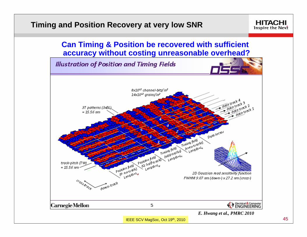
Timing and Position Recovery at very low SNR
Can Timing & Position be recovered with sufficient accuracy without costing unreasonable overhead?
E. Hwang et al., PMRC 2010

46IEEE SCV MagSoc, Oct 19th, 2010
4 Tb/sq.in. - including timing & position recovery
(Timing+Posn.)
TDMR Recording Channel Model:- Random Voronoi / Rectangular bit- 2D Gaussian Reader Sensitivity
8 Tbit/in2 channel bit density(100 % overhead for coding, timing, positioning, etc.)15.6 nm x 5.2 nm channel bit(3:1 BAR, 1632 KTPI × 4900 KBPI)1.75 grains per channel bit(14 Tgrains/in2, D=6.79 nm, sigma-area=50%)
Target: 4 Tbit/in2 customer density
System achieves > 4Tbit/sq.in. on 14 Tgrains/sq.in. media(0.29 customer bits/grain)Including overhead for error-control and timing and position recovery!
Bit
Erro
r Rat
e or
Se
ctor
Fai
lure
Rat
e
E. Hwang et al., PMRC 2010

47IEEE SCV MagSoc, Oct 19th, 2010
More Realistic Write Process and Bit-Aspect Ratios
Raw detector bit error-rates from the “GFP” model (no parity coding) Red curves denote 1D-BCJR, Green curves denote a 2D-BCJRBAR is held constant at 2.7 while bit-area is varied along horizontal axis
Bit
Erro
r Rat
e
0 2 4 6 8 10 12 14 Grains per Channel Bit
K. Chann et al., PMRC 2010
~2x Areal-Density increase from 2D vs. 1D signal-processingSignificant degradation from increasingly realistic write process
“GFP” model has medium with grain-pitch = 6.5 nm and σA/A = 17%
Readback is with a 2D Gaussian sensitivity function with T50 = 24 x 8 nm
VM is simple Voronoi model (grains written by centroid in rectangular bit) (GFP model becomes similar to VM model as complexity reduced: “full GFP” “red321GFP”)

48IEEE SCV MagSoc, Oct 19th, 2010
Limits on Magnetic Recording
Technology options for 1 Tbit/sq.in & beyond
Shingled Magnetic Recording (SMR)
Two-Dimensional Magnetic Recording (TDMR)
Data architecture and Systems Issues
Future Scenarios
Topics
Future Technology Options & Limits for Hard Disk Drives

49IEEE SCV MagSoc, Oct 19th, 2010
Data Architecture and Systems Issues
Hyatt Regency at Lake Tahoe, Incline Village, Nevada, May 3-7th, 2010
Hitachi GST
SCU, UCSC
Industry must work closely with customers to understand & address changes in performance characteristics
Growing Interest in Storage Architectures for Shingled recording

50IEEE SCV MagSoc, Oct 19th, 2010
Layout
A. Amer et al. “Design Issues for a Shingled Write Disk System” MSST 2010
Random access zone(non-shingled)
track-pitch ~= write-width
(fast access/settle times)
Log Access Zones(tightly-shingled)
track-pitch ~= ½ write-width
Shingled Zones are used as circular log-structured files
Most of data is stored at much higher TPI in these circular log files
Data Architecture and Systems Issues

51IEEE SCV MagSoc, Oct 19th, 2010
Tune for best average performance or best worst-case performance?
Y. Cassuto et al. “Indirection Systems for Shingled-Recording Disk Drives” MSST 2010
Data Architecture and Systems Issues

52IEEE SCV MagSoc, Oct 19th, 2010
Garth Gibson, Intermag, April 2009, Paper FA-06
Data Architecture and Systems Issues
(We really need that multi-element reader!)

53IEEE SCV MagSoc, Oct 19th, 2010
Limits on Magnetic Recording
Technology options for 1 Tbit/sq.in & beyond
Shingled Magnetic Recording (SMR)
Two-Dimensional Magnetic Recording (TDMR)
Data architecture and Systems Issues
Future Scenarios
Topics
Future Technology Options & Limits for Hard Disk Drives

54IEEE SCV MagSoc, Oct 19th, 2010
“Perfect” Inventions
Bicycle Hard Disk Drive
• fluid-bearing spindle with multiple disks • rotary actuator carrying multiple heads • slider with self-generated air-bearing • thermal μ-actuator for magnetic spacing• perpendicular recording mode
• two large similar-diameter wheels• front-wheel pivots with handlebars• rear wheel driven through sprocket &
chain from rotating pedals • operated in seated position
G. Tarnopolsky, 4th Intnl. Conf. IGNOIE-SOIM, Jan. 23–25, 2007, Sendai, Japan, 2007
• Hard Disk drives will be here for many decades to come

55IEEE SCV MagSoc, Oct 19th, 2010
Evolving Markets
access-timethroughput
Enterprise
Desktop
Mobilelow-powerrobustness
traditional Mobile & Desktop
“Bulk storage”(write-once
read-rarely)• internet &
the “Cloud”• home server /
DVR • business
records• archive &
library“The Long Tail”
Enterprise (transaction processing)
Perfect for“TDMR”
“data-tub”or
“bit-bucket”
traditional EnterpriseSolid-state “SSD”
“Flash”/Solid-state
traditional HDD2.5” & 3.5”
• 3.5” form-factor• many heads/disks• helium sealed • microactuator• moderate rpm
& access times• high data-rates
(~3 Gb/s)
HD
D
HD
Dtime (decades)
Conceptual picture showing storage capacities shifting towards solid-state and to“bulk” storage on HDD
(personal perspective)
future?
today
R. Wood, J. MMM 321 (2009) pp. 555–561

56IEEE SCV MagSoc, Oct 19th, 2010
Limits on Magnetic Recording• Projections of 1 Tbit/sq.in. & ~3 Gbit/s still seem well founded
Technology options for 1 Tbit/sq.in & beyond• BPMR - lower technology risk but greater manufacturing challenges & cost• HAMR - higher risks for technology & reliability but more compatible with
current HDD architecture & manufacturing processes• SMR/TDMR - low risk but major customer acceptance issues (especially for TDMR)
Shingled Magnetic Recording (SMR)• Gaining acceptance as at least an interim solution (early-implementation of BPMR
and HAMR looks increasingly challenging)
Two-Dimensional Magnetic Recording (TDMR)• Still much work to do to understand & minimize large gap between Shannon capacity
promising >0.5 bits per grain and realistic write-processes giving ~0.1 bits/grain
Data architecture and Systems Issues• Attention now being drawn to this topic - work starting in both academia & industry
Future Scenarios• HDD will be eased out of traditional markets, but the “bulk” data storage market will
become immense and be ruled by HDD data tubs (using TDMR, of course!)
Summary

57IEEE SCV MagSoc, Oct 19th, 2010
Call for nominations for Invited Speakers & “Symposiums”
Propose Symposium on Shingled- and 2D Magnetic Recording ?
~6 papers covering key areas:• Shingled Writing: heads, media, measurements, system integration • 2D readback/TDMR: multi-readers, ITI mitigation, 2D-detection • Data handling: Architecture, performance, interface, customer impact
Closes on Oct 28th: let me know, please, if you have ideas or suggestions for topics or speakers ([email protected])
Intermag 2011

58IEEE SCV MagSoc, Oct 19th, 2010All Rights Reserved, Copyright(C) 2003, Hitachi, Ltd. 58
back-up

59IEEE SCV MagSoc, Oct 19th, 2010
Abtract & Bio


![[Marvin Camras (Auth.)] Magnetic Recording Handbo(BookZa.org)](https://img.dokumen.tips/doc/110x75/55cf97f8550346d03394be5f/marvin-camras-auth-magnetic-recording-handbobookzaorg.jpg)