Embed Size (px)
Citation preview
Shilpa Bollineni, Glen Langston, John Ford, Randy McCullough and
Paul Demorest
DATA ACQUISITION ON THE 43M TELESCOPE
2
DATA ACQUISITION ON THE 43M TELESCOPE
• The Digital Acquisition System is a clone of GUPPI(Green Bank Ultimate Pulsar Processing Instrument).
• It was developed to be placed on the 43m telescope in the feed-box.
• Why we did this?
1) The limitation with the fiber modem on the frequency range which will be eliminated and we can observe at higher range.
2) We will have more dynamic range in the system as the S/N will be better.
3) As the prime-focus box is controlled we will have a more stable environment.
3
Heater Control Circuit
Teledyne VT6 Vacuum Gauge
Lakeshore Model 218
Temp Monitor
Bias Cards(2)
Vacuum Sensor #1
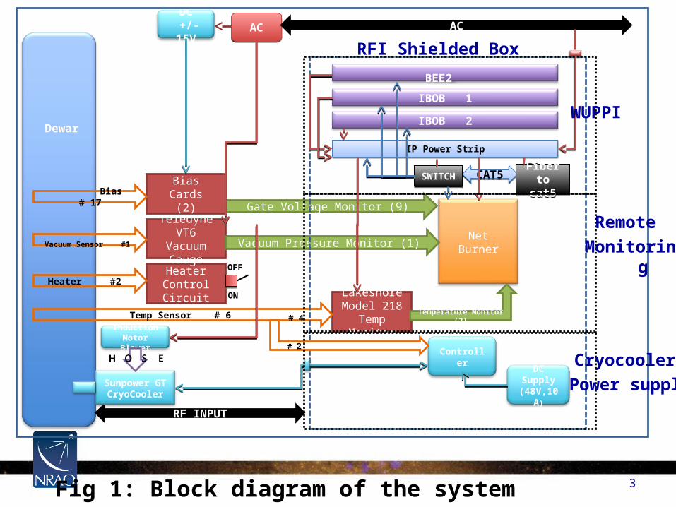
RFI Shielded Box
Net Burner
Heater #2
Bias # 17
Temp Sensor # 6
BEE2
IBOB 1
IBOB 2
Vacuum Pressure Monitor (1)
Gate Voltage Monitor (9)
DC +/-15V ACAC
Controller
Induction Motor Blower
AC
RF INPUT
Sunpower GT CryoCooler
Dewar
Temperature Monitor (2)
CAT5CAT5
DC Supply (48V,10A)
IP Power StripIP Power Strip
OFF
ON
# 2
# 4
Fig 1: Block diagram of the system
Fiber to cat5
Fiber to cat5
SWITCHSWITCH
WUPPI
Remote
Monitoring
Cryocooler
Power supply

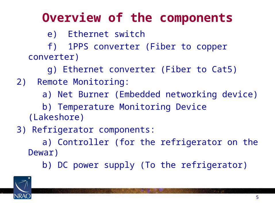
Overview of the components
4
1) WUPPI
a) IBOB’s (Sampling)
1) 8-bit sampling.
2) Bandwidth of 800MHZ.
b) BEE2 (Data Processing)
1) We have 4k channel FFT.
2) full polarization
c) IP power strip (Remotely control the power of the hardware)
d) Dual Synthesizer (800 MHz clock)
Overview of the components
e) Ethernet switch
f) 1PPS converter (Fiber to copper converter)
g) Ethernet converter (Fiber to Cat5)
2) Remote Monitoring:
a) Net Burner (Embedded networking device)
b) Temperature Monitoring Device (Lakeshore)
3) Refrigerator components:
a) Controller (for the refrigerator on the Dewar)
b) DC power supply (To the refrigerator)
5
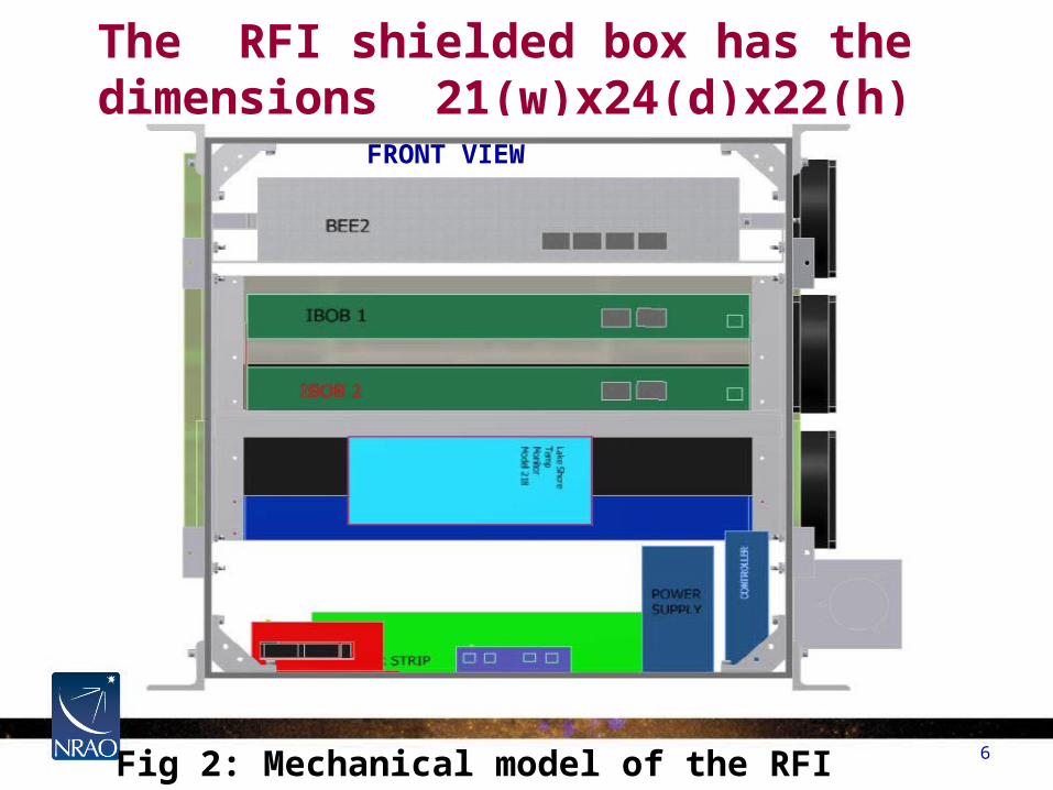
The RFI shielded box has the dimensions 21(w)x24(d)x22(h) inches
6Fig 2: Mechanical model of the RFI shielded box
FRONT VIEW
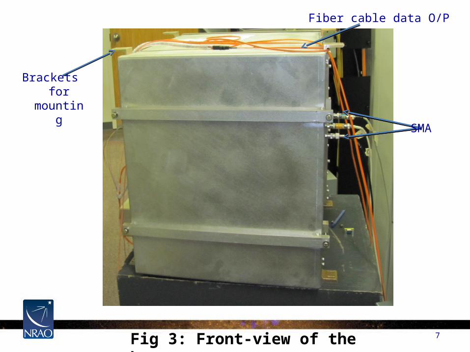
Fig 3: Front-view of the box 7
SMA
Fiber cable data O/P
Brackets for mounting
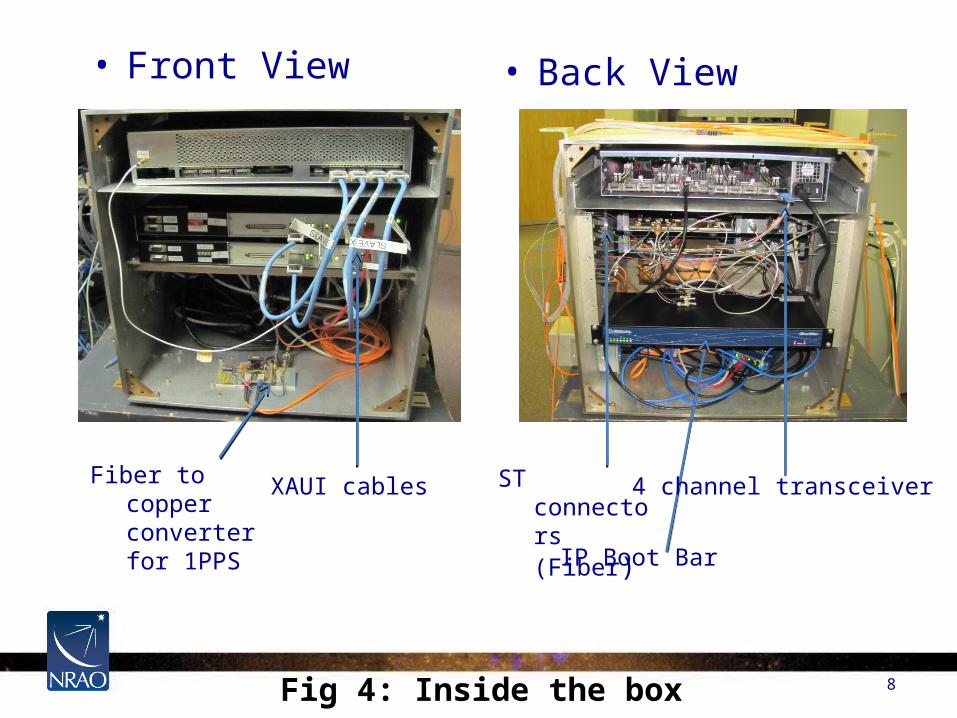
8Fig 4: Inside the box
• Front View • Back View
Fiber to copper converter for 1PPS
XAUI cables ST connectors (Fiber)
IP Boot Bar
4 channel transceiver
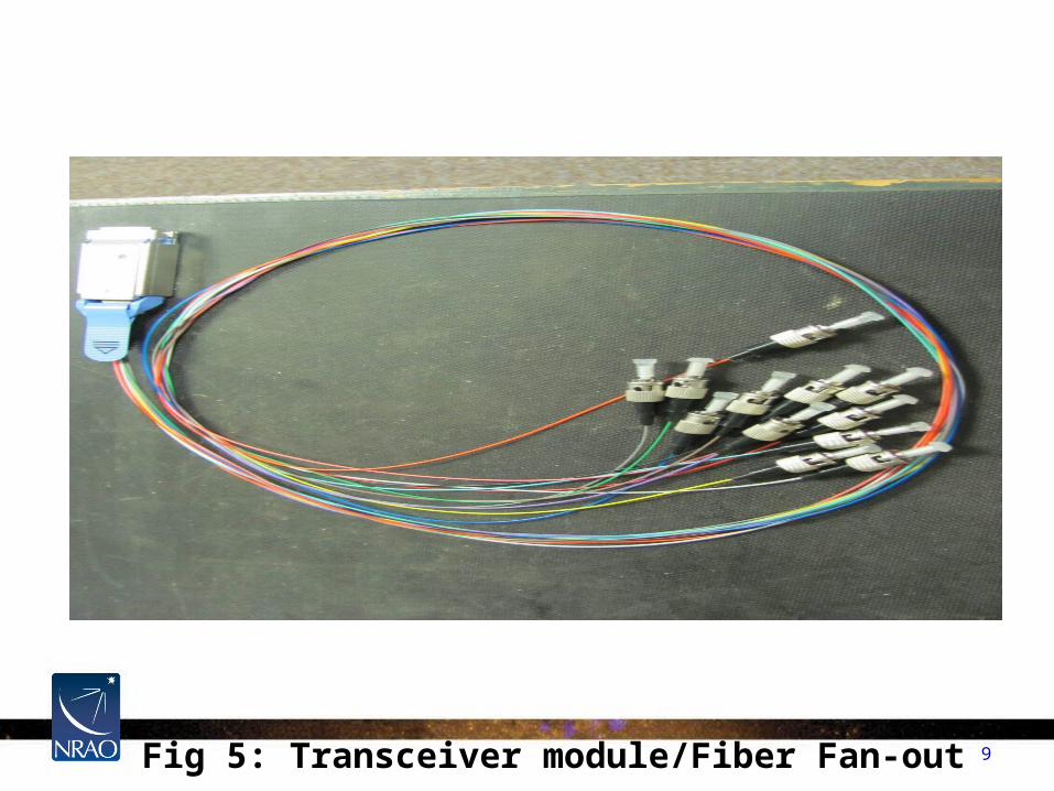
9Fig 5: Transceiver module/Fiber Fan-out
10
04
/18
/23
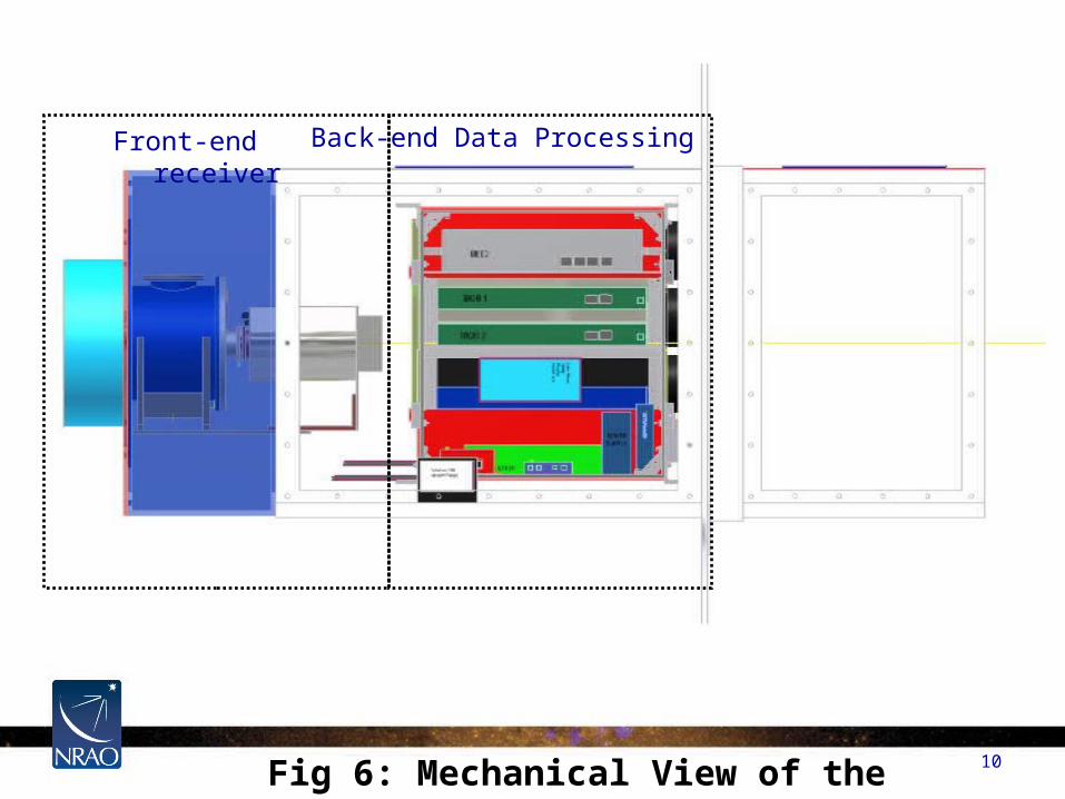
Fig 6: Mechanical View of the Front-End Box
Front-end receiver Back-end Data Processing
11
Different phases of testing
a) RFI test passed.
1) Frequency range: 20 MHz to 6.5 GHz no emissions.
b) Data was taken in the lab (plots follow).
b) Next the box will be placed in the 43m control room.
c) Finally it will be placed in the Front-end box so we can process the data at the antenna.
12
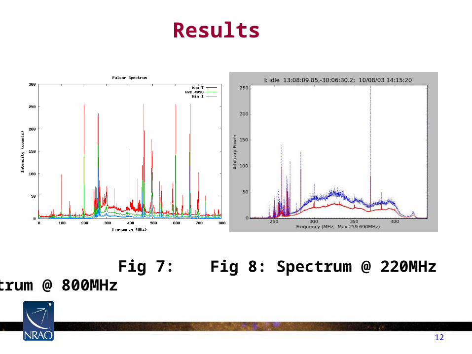
Results
Fig 7: Spectrum @ 800MHz Fig 8: Spectrum @ 220MHz
13
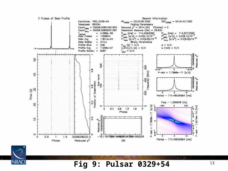
Fig 9: Pulsar 0329+54
14
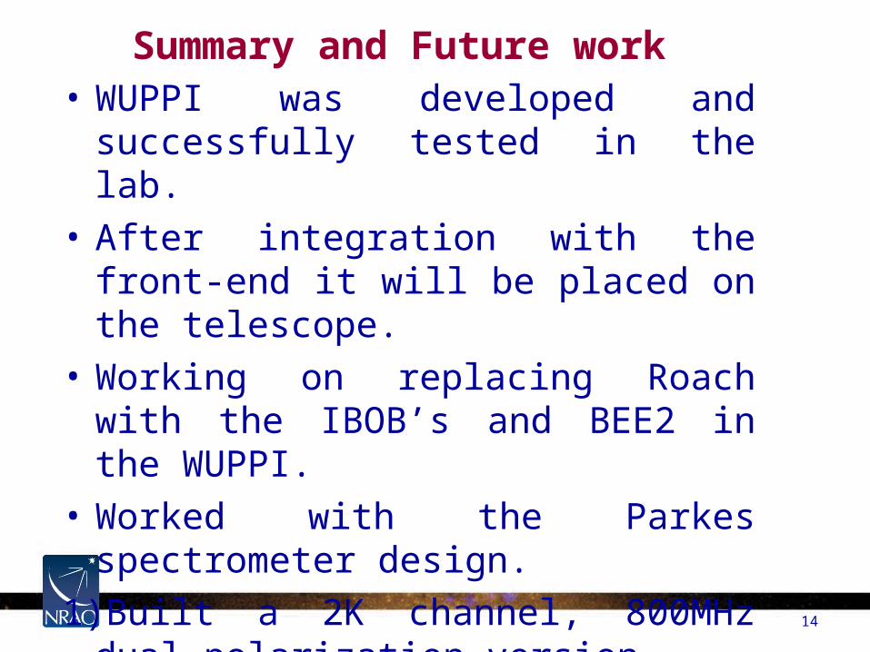
Summary and Future work• WUPPI was developed and successfully
tested in the lab.
• After integration with the front-end it will be placed on the telescope.
• Working on replacing Roach with the IBOB’s and BEE2 in the WUPPI.
• Worked with the Parkes spectrometer design.
1)Built a 2K channel, 800MHz dual polarization version.
2)Introduced the 1SFA concept from GUPPI into the design.
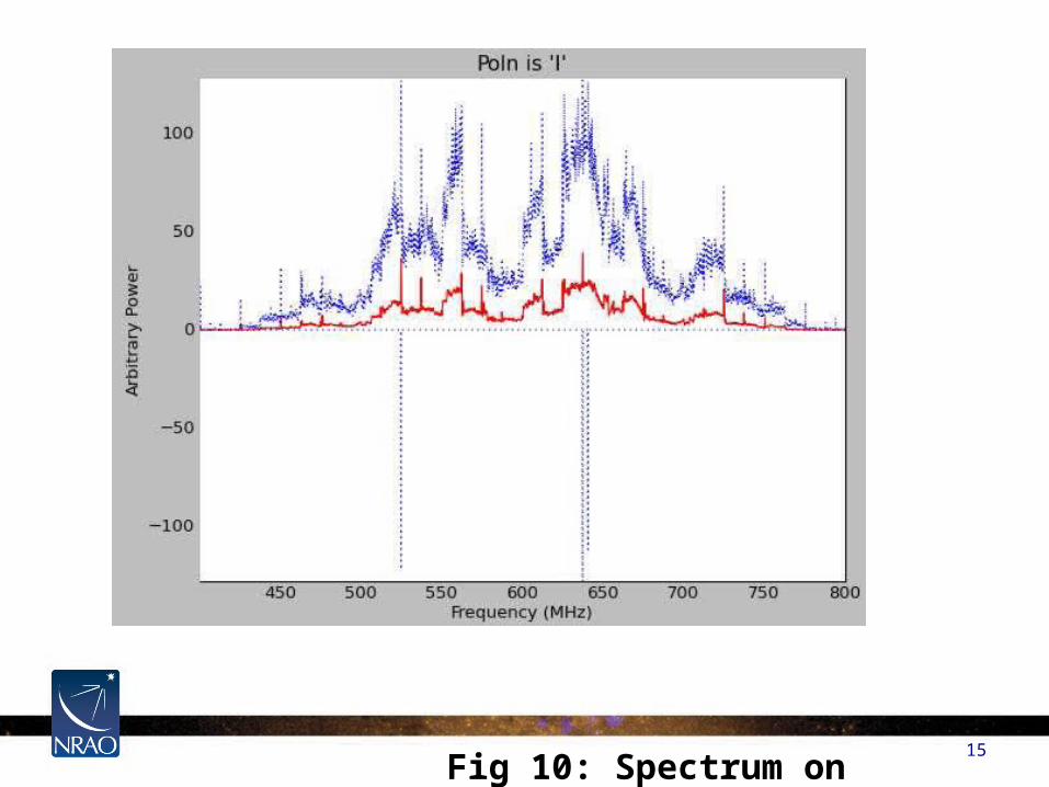
15 Fig 10: Spectrum on Roach

16 Fig 11: test signal @ 611 MHz
Acknowledgement
• Glen Langston
• John Ford
• Jeff Cromer
• Randy Mccullough
• Jason Ray
• Dennis Egan
• Gary Anderson
17
18