Embed Size (px)
Citation preview
9
Shift Invariant Biorthogonal Discrete Wavelet Transform
for EEG Signal Analysis
Juuso T. Olkkonen and Hannu Olkkonen VTT Technical Research Centre of Finland, 02044 VTT,
Department of Applied Physics, University of Kuopio, 70211 Kuopio,
Finland
1. Introduction
Since the discovery of the compactly supported conjugate quadrature filter (CQF) based
discrete wavelet transform (DWT) (Smith & Barnwell, 1986; Daubechies, 1988), a variety of
data and image processing tools have been developed. It is well known that real-valued
CQFs have nonlinear phase, which may cause image blurring or spatial dislocations in
multi-resolution analysis. In many applications the CQFs have been replaced by the
biorthogonal discrete wavelet transform (BDWT), where the low-pass scaling and high-pass
wavelet filters are symmetric and linear phase. In VLSI hardware the BDWT is usually
realized via the ladder network-type filter (Sweldens, 1988). Efficient lifting wavelet
transform algorithms implemented by integer arithmetic using only register shifts and
summations have been developed for VLSI applications (Olkkonen et al. 2005).
In multi-scale analysis the drawback of the BDWT is the sensitivity of the transform
coefficients to a small fractional shift [0,1]τ ∈ in the signal, which disturbs the statistical
comparison across different scales. There exist many approaches to construct the shift
invariant wavelet filter bank. Kingsbury (2001) proposed the use of two parallel filter banks
having even and odd number of coefficients. Selesnick (2002) has described the nearly shift
invariant CQF bank, where the two parallel filters are a half sample time shifted versions of
each other. Gopinath (2003) generalized the idea by introducing the M parallel CQFs, which
have a fractional phase shift with each other. Both Selesnick and Gopinath have constructed
the parallel CQF bank with the aid of the all-pass Thiran filters, which suffers from
nonlinear phase distortion effects (Fernandes, 2003).
In this book chapter we introduce a linear phase and shift invariant BDWT bank consisting
of M fractionally delayed wavelets. The idea is based on the B-spline interpolation and
decimation procedure, which is used to construct the fractional delay (FD) filters (Olkkonen
& Olkkonen, 2007). The FD B-spline filter produces delays τ =N/M (N, M∈N , N= 0,…,M-
1). We consider the implementation of the shift invariant FD wavelets, especially for the
VLSI environment. The usefulness of the method was tested in wavelet analysis of the EEG
signal waveforms.
www.intechopen.com
Discrete Wavelet Transforms - Theory and Applications
170
2. Theoretical considerations
2.1 Two-channel BDWT filter bank
The two-channel BDWT analysis filters are of the general form (Olkkonen et al. 2005)
1
0
11
( ) (1 ) ( )
( ) (1 ) ( )
K
K
H z z P z
H z z Q z
−−
= += − (1)
where 0( )H z is the Nth order low-pass scaling filter polynomial having the Kth order zero
at ω π= . ( )P z is polynomial in 1z− . 1( )H z is the corresponding Mth order high-pass
wavelet filter having Kth order zero at 0ω = . ( )Q z is polynomial in 1z− . For a two-channel
perfect reconstruction filter bank, the well known perfect reconstruction (PR) condition is
0 0 1 1
0 0 1 1
( ) ( ) ( ) ( ) 2
( ) ( ) ( ) ( ) 0
kH z G z H z G z z
H z G z H z G z
−+ =− + − = (2)
where 0( )G z and 1( )G z are the low-pass and high-pass reconstruction filters defined as
0 1
1 0
( ) ( )
( ) ( )
G z H z
G z H z
= −= − − (3)
A typical set of the scaling and wavelet filter coefficients is given in (Olkkonen et al. 2005). In this work we apply the following essential result concerning on the PR condition (2).
Lemma 1: If 0( )H z and 1( )H z are the scaling and wavelet filters, the following modified
analysis and synthesis filters obey the PR condition
0 0
11 1
10 0
1 1
( ) ( ) ( )
( ) ( ) ( )
( ) ( ) ( )
( ) ( ) ( )
H z P z H z
H z P z H z
G z P z G z
G z P z G z
−−
== −== −
(4)
where P(z) is any polynomial in 1z− and 1( )P z− its inverse. Proof: The result can be proved
by direct insertion of (4) into (2).
2.2 Fractional delay B-spline filter
The ideal FD operator has the z-transform
( , )D z z ττ −= (5)
where [0,1]τ ∈ . In (Olkkonen & Olkkonen, 2007) we have described the FD filter design
procedure based on the B-spline interpolation and decimation procedure for the
construction of the fractional delays /N Mτ = ( , , 0,1,..., 1)N M N M∈ = −N . The FD filter
has the following representation
1( , , ) ( ) ( ) ( )Np p
MD N M z z z z F zβ β− −
↓⎡ ⎤= ⎣ ⎦ (6)
www.intechopen.com

Shift Invariant Biorthogonal Discrete Wavelet Transform for EEG Signal Analysis
171
where ( )p zβ is the discrete B-spline filter (Appendix I). Decimation by M is denoted by
M↓ , and the polynomial ( )F z is of the form
1
1 1 1
1 1 1( )
1
p pM Mk
p pk o
zF z z
zM M
− − −− − − =⎛ ⎞ ⎛ ⎞−= =⎜ ⎟ ⎜ ⎟⎜ ⎟− ⎝ ⎠⎝ ⎠ ∑ (7)
For convenience we use the following polyphase decomposition
1
0
( ) ( ) ( )M
M kp k
k
z F z P z zβ − −=
= ∑ (8)
By inserting (8) into (6) we have
1( , , ) ( ) ( )p ND N M z z P zβ −= (9)
Table I gives the polyphase components ( )NP z for 4M = and 0,1,...,N M= . It appears
generally that 0( ) ( )pP z zβ= and 1( ) ( ).M pP z z zβ−= Hence, (0, , ) 1D M z = and 1( , , )D M M z z−= . The implementation of the inverse discrete B-spline filter 1( )p zβ − in (9) is
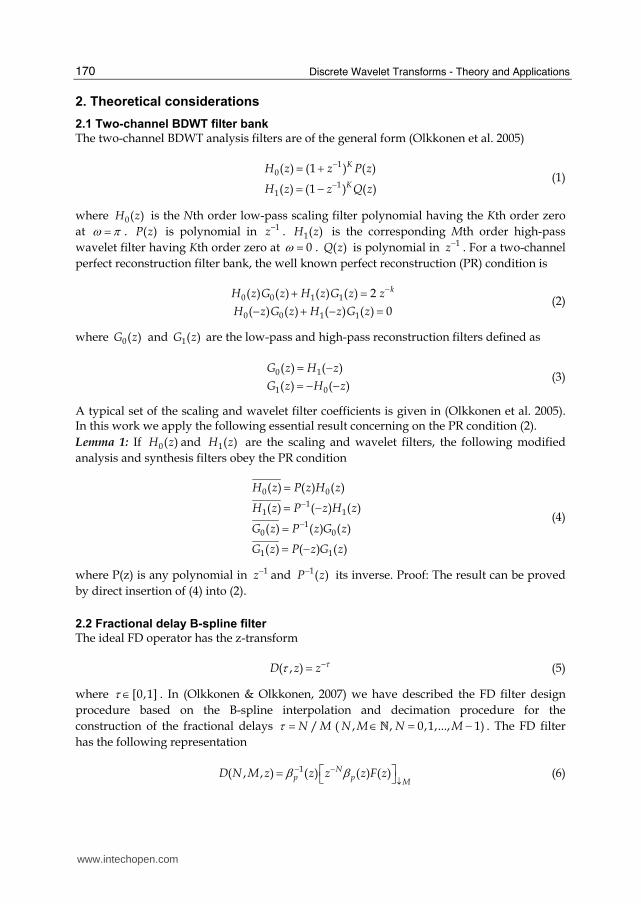
described in Appendix I. Fig. 1 shows the magnitude and phase spectra of the FD B-spline
filter (9) for 4M = and 1,2 and 3N = .
2.3 FD BDWT bank
As a direct application of Lemma 1, the fractionally delayed BDWT consists of the analysis
and synthesis filters ( 0,1,2,..., 1N M= − )
0 0
11 1
10 0
1 1
( , , ) ( , , ) ( )
( , , ) ( , , ) ( )
( , , ) ( , , ) ( )
( , , ) ( , , ) ( )
H N M z D N M z H z
H N M z D N M z H z
G N M z D N M z G z
G N M z D N M z G z
−−
== −== −
(10)
The FD B-spline filter (9) suits readily for the implementation of the FD BDWT bank (10).
For example, if we construct the four parallel filter banks, we select 4M = and
0,1,2 and 3N = . For M=4 the wavelet filter 1(0,4, )H z equals the original 1( )H z , which is
FIR. However, the filters 1(1,4, )H z , 1(2,4, )H z and 1(3,4, )H z are IIR-type. In the following
we present a novel modification of the FD BDWT filter bank (10), where all FD wavelet
filters are FIR-type.
Table I. Polyphase components ( )NP z for 4M = and 0,1,...,N M= ( 4p = ).
www.intechopen.com
Discrete Wavelet Transforms - Theory and Applications
172
Fig. 1. The FD B-spline ( 4p = ) filter for 4M = and 1,2 and 3N = .
2.4 FIR FD wavelet filters
In VLSI and microprocessor environment the FIR filters are preferable due to the
straightforward implementation by direct convolution. In tree structured multi-scale
analysis the nondelayed scaling coefficients are fed to the following scale and only the
wavelet coefficients are fractionally delayed. Next we describe a modification of the FD
BDWT bank (10), where all the FD wavelet filters are FIR. The idea is based on the fact that
only the relative time shift of the wavelet coefficients is essential for shift invariance. Hence,
due to Lemma 1 we may replace the original scaling and wavelet filters by
10 0
1 1
(0, , ) ( ) ( )
(0, , ) ( ) ( )
p
p
H M z z H z
H M z z H z
ββ−=
= − (11)
which obey the PR condition. Since the discrete B-spline filter ( )p zβ contains no zeroes at
1z = − , the regulatory degree (the number of zeros at 1z = − ) of the scaling filter is not
affected. The corresponding fractionally delayed wavelet filters are
1 1( , , ) ( ) ( ) 1,2,..., 1NH N M z P z H z N M= − = − (12)
Now, for 0,1,..., 1N M= − all the wavelet filters are FIR-type and they are the fractionally
delayed versions of each other. The polyphase components ( )NP z− in (12) have high-pass
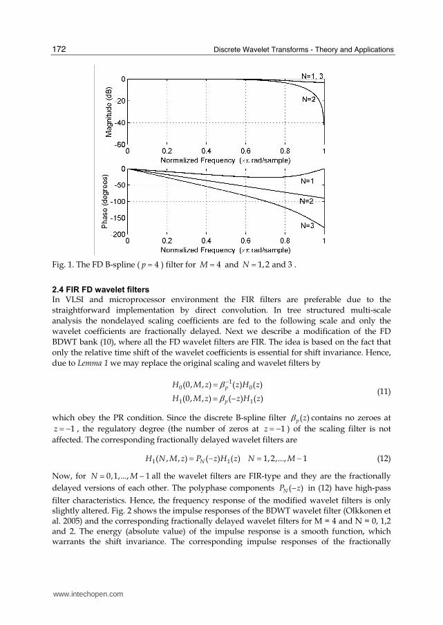
filter characteristics. Hence, the frequency response of the modified wavelet filters is only slightly altered. Fig. 2 shows the impulse responses of the BDWT wavelet filter (Olkkonen et al. 2005) and the corresponding fractionally delayed wavelet filters for M = 4 and N = 0, 1,2 and 2. The energy (absolute value) of the impulse response is a smooth function, which warrants the shift invariance. The corresponding impulse responses of the fractionally
www.intechopen.com
Shift Invariant Biorthogonal Discrete Wavelet Transform for EEG Signal Analysis
173
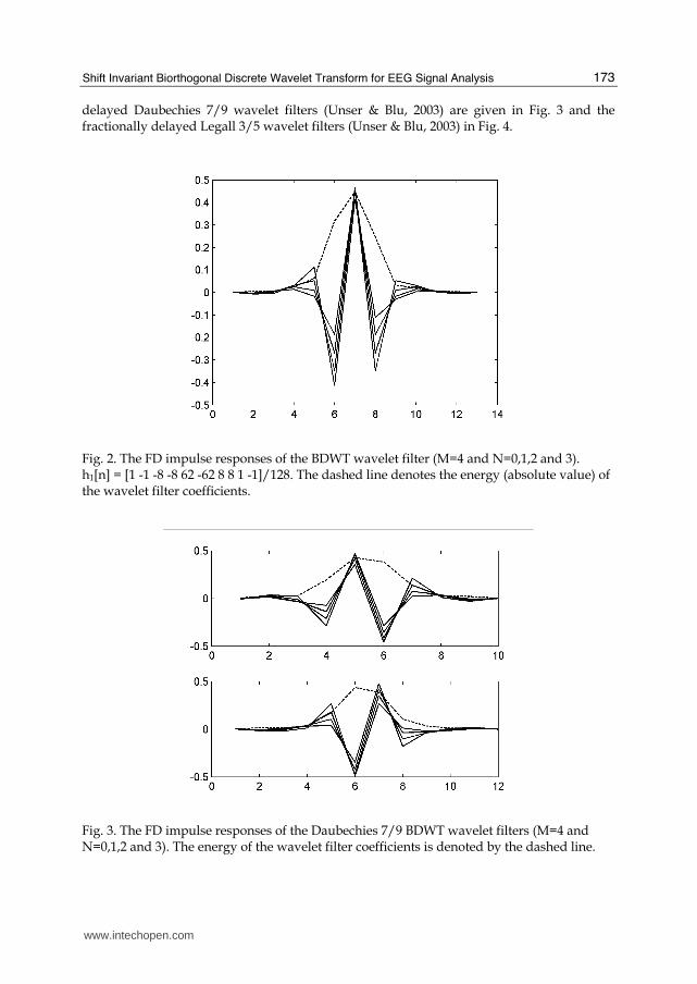
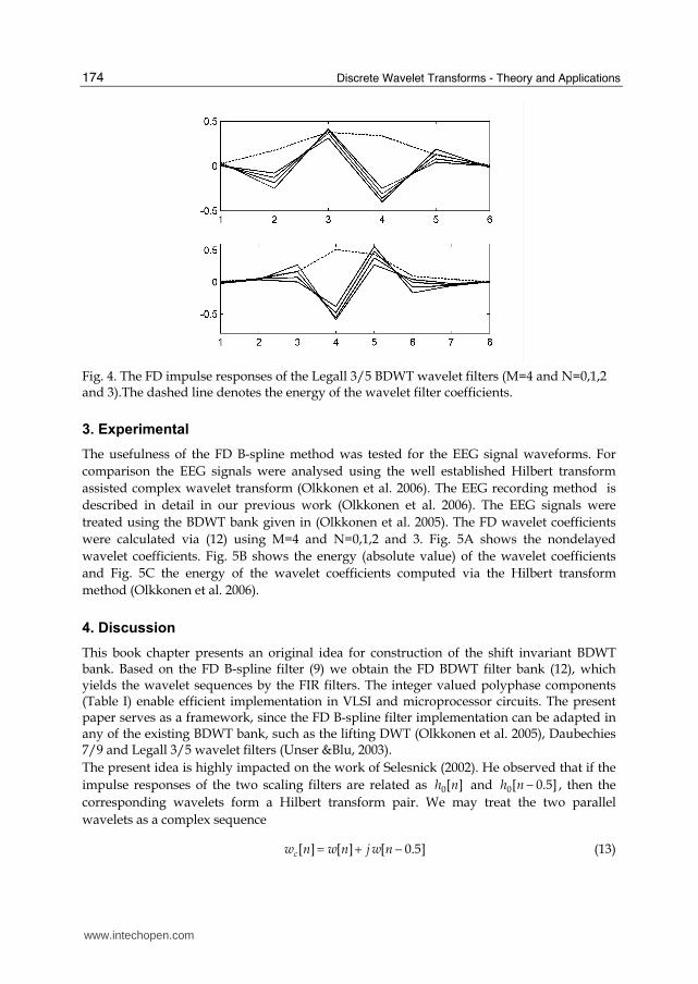
delayed Daubechies 7/9 wavelet filters (Unser & Blu, 2003) are given in Fig. 3 and the fractionally delayed Legall 3/5 wavelet filters (Unser & Blu, 2003) in Fig. 4.
Fig. 2. The FD impulse responses of the BDWT wavelet filter (M=4 and N=0,1,2 and 3). h1[n] = [1 -1 -8 -8 62 -62 8 8 1 -1]/128. The dashed line denotes the energy (absolute value) of the wavelet filter coefficients.
Fig. 3. The FD impulse responses of the Daubechies 7/9 BDWT wavelet filters (M=4 and N=0,1,2 and 3). The energy of the wavelet filter coefficients is denoted by the dashed line.
www.intechopen.com
Discrete Wavelet Transforms - Theory and Applications
174
Fig. 4. The FD impulse responses of the Legall 3/5 BDWT wavelet filters (M=4 and N=0,1,2 and 3).The dashed line denotes the energy of the wavelet filter coefficients.
3. Experimental
The usefulness of the FD B-spline method was tested for the EEG signal waveforms. For
comparison the EEG signals were analysed using the well established Hilbert transform
assisted complex wavelet transform (Olkkonen et al. 2006). The EEG recording method is
described in detail in our previous work (Olkkonen et al. 2006). The EEG signals were
treated using the BDWT bank given in (Olkkonen et al. 2005). The FD wavelet coefficients
were calculated via (12) using M=4 and N=0,1,2 and 3. Fig. 5A shows the nondelayed
wavelet coefficients. Fig. 5B shows the energy (absolute value) of the wavelet coefficients
and Fig. 5C the energy of the wavelet coefficients computed via the Hilbert transform
method (Olkkonen et al. 2006).
4. Discussion
This book chapter presents an original idea for construction of the shift invariant BDWT bank. Based on the FD B-spline filter (9) we obtain the FD BDWT filter bank (12), which yields the wavelet sequences by the FIR filters. The integer valued polyphase components (Table I) enable efficient implementation in VLSI and microprocessor circuits. The present paper serves as a framework, since the FD B-spline filter implementation can be adapted in any of the existing BDWT bank, such as the lifting DWT (Olkkonen et al. 2005), Daubechies 7/9 and Legall 3/5 wavelet filters (Unser &Blu, 2003).
The present idea is highly impacted on the work of Selesnick (2002). He observed that if the
impulse responses of the two scaling filters are related as 0[ ]h n and 0[ 0.5]h n − , then the
corresponding wavelets form a Hilbert transform pair. We may treat the two parallel
wavelets as a complex sequence
[ ] [ ] [ 0.5]cw n w n j w n= + − (13)
www.intechopen.com
Shift Invariant Biorthogonal Discrete Wavelet Transform for EEG Signal Analysis
175
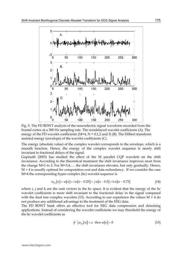
Fig. 5. The FD BDWT analysis of the neuroelectric signal waveform recorded from the frontal cortex at a 300 Hz sampling rate. The nondelayed wavelet coefficients (A). The energy of the FD wavelet coefficients (M=4, N = 0,1,2 and 3) (B). The Hilbert transform assisted energy (envelope) of the wavelet coefficients (C).
The energy (absolute value) of the complex wavelet corresponds to the envelope, which is a smooth function. Hence, the energy of the complex wavelet sequence is nearly shift invariant to fractional delays of the signal. Gopinath (2003) has studied the effect of the M parallel CQF wavelets on the shift invariance. According to the theoretical treatment the shift invariance improves most from the change M=1 to 2. For M=3,4,…. the shift invariance elevates, but only gradually. Hence, M = 4 is usually optimal for computation cost and data redundancy. If we consider the case M=4 the corresponding hyper complex (hc) wavelet sequence is
[ ] [ ] [ 0.25] [ 0.5] [ 0.75]hcw n w n i w n j w n k w n= + − + − + − (14)
where i, j and k are the unit vectors in the hc space. It is evident that the energy of the hc wavelet coefficients is more shift invariant to the fractional delay in the signal compared with the dual tree complex wavelets (13). According to our experience the values M > 4 do not produce any additional advantage to the treatment of the EEG data. The FD BDWT bank offers an effective tool for EEG data compression and denoising applications. Instead of considering the wavelet coefficients we may threshold the energy of the hc wavelet coefficients as
[ ] [ ] 0hcif w n then w nε< = (15)
www.intechopen.com
Discrete Wavelet Transforms - Theory and Applications
176
where ε is a small number. Due to the smooth behaviour of the energy function, ε can be made relatively high compared with the conventional wavelet denoising methods. In tree structured BDWT applications only the nondelayed scaling sequence is fed to the next scale. Usually the scaling sequence is not thresholded, but only the wavelet coefficients. The FD BDWT bank does not increase the memory requirement (redundancy) compared with the original nondelayed BDWT bank, since the reconstruction of the data can be performed by knowing only the nondelayed scaling and wavelet sequences. The FD BDWT bank can be considered as a subsampling device, which improves the quality of the critically sampled wavelet sequence. As an example we consider the multi-scale analysis of the neuroelectric signal (Fig. 5). The energy of the signal in different scales can be estimated with the aid of the Hilbert transform (Olkkonen et al. 2006). Applying the result of this work the energy of the wavelet sequence [ ]hcw n (14) approaches closely to the energy (envelope) of the signal. However, the delayed wavelet sequence is produced only by the polyphase filter
( )NP z (N=1,2,…,M-1)(12), while the Hilbert transform requires the FFT based signal processing (Olkkonen et al. 2006). In the EEG signal recorded from the frontal cortex, the spindle waves have concentrated energy, which is clearly revealed both by the FD BDWT and the Hilbert transform analysis (Fig. 5). The energy content of the EEG signal yielded by the two different methods is remarkably similar. The essential difference compared with the half-sample shifted CQF filter bank (Selesnick, 2002) is the linear phase of the BDWT bank and the FD B-spline filters adapted in this work. The shifted CQF filter bank is constructed with the aid of the all-pass Thiran filters and the scaling and wavelet coefficients suffer from nonlinear phase distortion effects (Fernandes, 2003). The linear phase warrants that the wavelet sequences in different scales are accurately time related. The FD wavelet coefficients enable the high resolution computation of the cross and autocorrelation and other statistical functions.
Appendix I
The discrete B-spline filter
B-splines ( )p tβ are defined as p -times convolution of a rectangular pulse
1 0 1
( ) ( ) ( ) ( ) ( )0p
p times
for tt p t p t p t p t
elsewhereβ ≤ ≤⎧= ∗ ∗ = ⎨⎩…'***(***) (16)
The Laplace transform of the B-spline comes from
{ } ( )0
1 1( ) (1 ) ( ) 1 ( 1)
p k sps s k
p p pk
p eL p t e s e
ks s sβ −− −
=⎛ ⎞= − ⇒ = − = − ⎜ ⎟⎝ ⎠∑ (17)
and the inverse Laplace transform gives the time domain solution
1
0
1( ) ( 1) ( )
( 1)!
ppk
pk
pt t k
kpβ −+=
⎛ ⎞= − −⎜ ⎟− ⎝ ⎠∑ (18)
The discrete B-spline [ ]p nβ equals to the continuous B-spline at integer values of time. Hence, the Laplace transform (17) and the z-transform of the discrete B-spline have inverse transforms which coincide at integer values in the time domain. Using the relation
www.intechopen.com
Shift Invariant Biorthogonal Discrete Wavelet Transform for EEG Signal Analysis
177
1
1 1
( 1)!
p
p
tL
ps
−− +⎛ ⎞ =⎜ ⎟ −⎝ ⎠ (19)
we obtain the z-transform of the discrete B-spline
{ } 1 11( ) [ ] (1 ) ( )(1 )p ps
p p ppz Z n Z L e N z z
sβ β − − −⎧ ⎫⎛ ⎞= = − = −⎨ ⎬⎜ ⎟⎝ ⎠⎩ ⎭ (20)
where
1
1
0
1( )
( 1)!
pn
p pn
nN z Z L z
ps
−∞− −=
⎧ ⎫⎛ ⎞= =⎨ ⎬⎜ ⎟ −⎝ ⎠⎩ ⎭ ∑ (21)
We have 11( ) 1 /(1 )N z z−= − . By differentiating in respect to z we obtain a recursion
1
( )( )
pp
dN zzN z
p d z+
−= (22)
As an example we may obtain the discrete B-spline for p=4 as 1 24( ) (1 4 ) /6z z zβ − −= + + .
The inverse discrete B-spline filter can be written as a cascade realization
11 1
1 1 1 1
1 1( ) ( ) ( )
1 1
n m n m
p i ji j i ji j
z c c S z R zb z b z
β − − −= = = == =− −∏ ∏ ∏ ∏ (23)
where c is a constant and the roots 1ib ≤ and 1jb > . The ( )iS z filters in (23) can be directly
implemented. The ( )jR z filters in (23) can be implemented by the following recursive
filtering procedure. First we replace z by z-1
1 1 11
1 1 1 1
1 ( ) ( )( ) ( )
( )1 1 ( )
ji i
j j
b zY z Y zR z R z
U zb z b z U z
− − −−− − − −−= = ⇒ = =− − (24)
where ( )U z and ( )Y z denote z-transforms of the input [ ]u n and output [ ]y n signals
( 0,1,2,..., )n N= . The 1( )U z− and 1( )Y z− are the z-transforms of the time reversed input
[ ]u N n− and output [ ]y N n− . The 1( )jR z− filter is stable having a root 1jb− inside the unit
circle. The following Matlab program rfilter.m demonstrates the computation procedure:
function y=rfilter(u,b) u=u(end:-1:1); y=filter([0 -1/b],[1 -1/b],u); y=y(end:-1:1);
5. References
Daubechies, I. (1988). Orthonormal bases of compactly supported wavelets. Commmun. Pure Appl. Math., Vol. 41, 909-996.
www.intechopen.com
Discrete Wavelet Transforms - Theory and Applications
178
Fernandes,F., Selesnick , I.W., van Spaendonck, R. & Burrus, C. (2003). Complex wavelet transforms with allpass filters, Signal Processing, Vol. 83, 1689-706.
Gopinath, R.A. (2003).The phaselet transform - An integral redundancy nearly shift invariant wavelet transform, IEEE Trans. Signal Process. Vol. 51, No. 7, 1792-1805.
Kingsbury, N.G. (2001). Complex wavelets for shift invariant analysis and filtering of signals. J. Appl. Comput. Harmonic Analysis. Vol. 10, 234-253.
Olkkonen, H., Pesola, P. & Olkkonen, J.T. (2005). Efficient lifting wavelet transform for microprocessor and VLSI applications. IEEE Signal Process. Lett. Vol. 12, No. 2, 120-122.
Olkkonen, H., Pesola, P., Olkkonen, J.T. & Zhou, H. (2006). Hilbert transform assisted complex wavelet transform for neuroelectric signal analysis. J. Neuroscience Meth. Vol. 151, 106-113.
Olkkonen, J.T. & and Olkkonen, H. (2007). Fractional Delay Filter Based on the B-Spline Transform, IEEE Signal Processing Letters, Vol. 14, No. 2, 97-100.
Selesnick, I.W. (2002). The design of approximate Hilbert transform pairs of wavelet bases. IEEE Trans. Signal Process. Vol. 50, No. 5, 1144-1152.
Smith, M.J.T. & Barnwell, T.P. (1986). Exaxt reconstruction for tree-structured subband coders. IEEE Trans. Acoust. Speech Signal Process. Vol. 34, 434-441.
Sweldens, W. (1988). The lifting scheme: A construction of second generation wavelets. SIAM J. Math. Anal. Vol. 29, 511-546.
Unser, M. & Blu,T. (2003), Mathematical properties of the JPEG2000 wavelet filters, IEEE Trans. Image Process., Vol. 12, No. 9, 1080-1090.
www.intechopen.com
Discrete Wavelet Transforms - Theory and ApplicationsEdited by Dr. Juuso T. Olkkonen
ISBN 978-953-307-185-5Hard cover, 256 pagesPublisher InTechPublished online 04, April, 2011Published in print edition April, 2011
InTech EuropeUniversity Campus STeP Ri Slavka Krautzeka 83/A 51000 Rijeka, Croatia Phone: +385 (51) 770 447 Fax: +385 (51) 686 166www.intechopen.com
InTech ChinaUnit 405, Office Block, Hotel Equatorial Shanghai No.65, Yan An Road (West), Shanghai, 200040, China
Phone: +86-21-62489820 Fax: +86-21-62489821
Discrete wavelet transform (DWT) algorithms have become standard tools for discrete-time signal and imageprocessing in several areas in research and industry. As DWT provides both frequency and locationinformation of the analyzed signal, it is constantly used to solve and treat more and more advanced problems.The present book: Discrete Wavelet Transforms: Theory and Applications describes the latest progress inDWT analysis in non-stationary signal processing, multi-scale image enhancement as well as in biomedicaland industrial applications. Each book chapter is a separate entity providing examples both the theory andapplications. The book comprises of tutorial and advanced material. It is intended to be a reference text forgraduate students and researchers to obtain in-depth knowledge in specific applications.
How to referenceIn order to correctly reference this scholarly work, feel free to copy and paste the following:
Juuso T. Olkkonen and Hannu Olkkonen (2011). Shift Invariant Biorthogonal Discrete Wavelet Transform forEEG Signal Analysis, Discrete Wavelet Transforms - Theory and Applications, Dr. Juuso T. Olkkonen (Ed.),ISBN: 978-953-307-185-5, InTech, Available from: http://www.intechopen.com/books/discrete-wavelet-transforms-theory-and-applications/shift-invariant-biorthogonal-discrete-wavelet-transform-for-eeg-signal-analysis