Embed Size (px)
Citation preview

1
SHAKE TABLE TESTS ON UNREINFORCED LOAD-BEARING
MASONRY STRUCTURAL ELEMENTS
Christophe MORDANT1 and Hervé DEGEE2
ABSTRACT
The field of application of unreinforced load-bearing masonry has been widely extended in the past
two decades thanks to a better understanding of the structural behaviour and a better control of
production methods, leading to improvements of their design and a more rational use of the material.
Multi-storey apartment buildings and lightweight concrete houses are now widespread. Nevertheless,
this structural solution is still questionable in seismic areas, even for low-to-moderate activity, and
requires additional investigations to properly understand the structural behaviour under these specific
horizontal dynamic actions. Moreover, these new applications are associated to new requirements,
like the individual comfort or the low energy-consumption, achieved by resorting to technical
solutions that are likely to influence on the dynamic response of the structure.
In this context, experimental shake table tests have been performed on unreinforced load-
bearing clay masonry sub-structures. In this paper, the main observations derived from the direct
experimental measurements are summarized and followed by resulting preliminary conclusions. A
major observation is a significant rocking behaviour for the tests with the highest seismic input,
strongly influenced by the presence of rubber devices and the frame effect. Dynamic characterization
of the tested specimens (natural frequencies and modal shapes) is also detailed.
INTRODUCTION
For many centuries, masonry has been used for private dwellings as well as for churches, town halls,
etc. Historically, the design of these buildings has essentially been relying on good practice methods
and was left under the combined responsibility of the architects and builders, with no or limited
engineering input. The past 20 years have however seen an increasing interest of engineers in this
field and led to improvements in the knowledge and design of masonry structures, leading for instance
to the spreading of multi-storey apartment buildings or of lightweight concrete houses (see Figure 1)
and to a more rational use of the materials, reducing thus the cost and consumption. All these
considerations are supported by the “Eurocode 6 – Design of masonry structures” (Eurocode 6, 2004)
Figure 1. Multi-storey apartments (left) and lightweight concrete house (right)
1 PhD student, University of Liège, Liège, Belgium, [email protected] 2 Associate Professor, Hasselt University, Hasselt, Belgium, [email protected]

2
Besides this, several earthquakes in Europe and, in particular, in North-Western European
countries like Belgium (see Figure 2), resulted in the awareness of the governments and public
authorities that the seismic event has to be considered in the structural design. Nevertheless, the
consideration of the earthquake impacts cannot be adequate without an additional proper
understanding of the structural behaviour under these specific horizontal dynamic actions. Basic
principles of this characterization and the consequent analysis and design methodologies are proposed
in (Tomazevic, 1999) and are at the base of a specific chapter on masonry structures in the “Eurocode
8 – Design of structures for earthquake resistance” (Eurocode 8, 2004). These general considerations
need however to be specifically transposed to each particular type of masonry structures.
Figure 2. Liège, earthquake in November 1983
Several researches have been carried out in the past 15 years (e.g. Kazemi et al., 2010,
Nakagawa et al., 2012 and Schermer, 2005) in this field. These were however mainly dedicated to
other type of masonry and other construction methods than the most common types of masonry
structural configurations used in North-Western Europe, namely relatively thin bearing walls (from 10
to 20 cm) with high strength units (compression resistance up to 15 N/mm² or even more) working at a
very high compression ratio under service loads and more and more implemented using horizontal
thin-bed layered jointing and open "tongue and groove" vertical joints for constructional efficiency
purpose.
Moreover, a review of the available literature shows out that, on the one hand, many researchers
are pointing out the over-conservatism and the mismatch with common construction habits of the
current standards design rules (Degée et al., 2007, Karantoni & Lirantzaki, 2009) when comparing the
resistance predicted based on code design rules with experimental results on full scale houses. Such
discrepancy is probably due to the fact that the codes don’t commonly consider the contribution of the
walls perpendicular to the seismic action and that the horizontal elements, such as the lintels or the
spandrels, are also often neglected or modelled questionably. On the other hand, additional
requirements are now needed when designing apartment buildings in order to fit with the standards in
terms of individual comfort (in particular in terms of acoustic and thermal performances). Limited
research works have dealt with the consequences of technical solutions (Figure 3) developed in this
purpose, but they were focused on the structural strength and static behaviour, with no interests of the
influences on the dynamic behaviour and on the seismic response.
Figure 3. Technical solution for the acoustic performances
Consequently, experimental tests on unreinforced masonry structural elements (walls) and sub-
structures have been performed in collaboration with the Earthquake and Large Structures Laboratory
(EQUALS) at the University of Bristol, in the framework of the SERIES project. The experimental
campaign was composed of two sets of specimens. The first set contains four simple unreinforced
masonry walls, two of them including soundproofing devices (see Figure 4), and follows a double aim.
The first one is to better understand the general behaviour of single walls in dynamic conditions in the
perspective of calibrating theoretical models and of extending the conclusions to entire buildings. The
second one is to investigate the consequences of the use of rubber elements placed for acoustic reasons

C. Mordant and H. Degée 3
on the seismic behaviour by comparing the structural response of walls with the same geometry, but
respectively with or without soundproofing elements.
Figure 4. First set of specimens
The second set of specimens includes two unreinforced masonry frames with T- or L-shaped
piers (see Figure 5). The objectives of these tests are to improve the design methodologies by
considering properly the frame effect and the contribution of walls perpendicular to the seismic action.
Neglecting these contributions may appear as safe from a pure "resistance" point of view. It can
however be more problematic with regard to the dynamic response of the structures. Indeed, the
response depends on the stiffness of the structures, which is increased because of the presence of
perpendicular walls. Neglecting them can thus be unsafe when referring to the current methodologies
proposed by the standards. This second experimental set is focused on (i) the frame behaviour and (ii)
the influence of the spanning structural elements. Beside these general objectives, the geometry of the
frame with T-shaped piers has also been designed to investigate (iii) the effects of a global torsion
triggered by vertical piers oriented differently, while the frame with L-shaped piers is dedicated to (iv)
the comparison of different connection methods (a classical alternated pattern or a glued connection)
between the shear wall and the perpendicular flange wall constituting the piers and (v) the influence of
the gravity loading case, in particular the case of a frame with piers partially loaded shaken in the
direction perpendicular to the plan of the loaded walls.
Figure 5. Second set of specimens
This paper describes the results of shaking table tests carried out to contribute to these issues.
Both sets use the same instrumental devices, namely accelerometers and LVDTS, and an Imetrum
Vision system to measure and characterize the wall behaviour. The main observations derived from
the direct experimental measurements are summarized and followed by resulting preliminary
conclusions. The main observation is a significant rocking behaviour for the tests with the highest
seismic input, strongly influenced by the presence of rubber devices and the frame effect. The
dynamic characterization of the specimens (modal frequencies and shapes) is also a major outcome.
DESCRIPTION OF THE TESTS
The four specimens of the first set are simple unreinforced load-bearing walls with thin bed-layered
clay masonry units and empty vertical joints. They have two different aspects (Length x Height),
namely close to 0.4 and 1, to target different failure modes, one in shear and the other one in bending
respectively. As said in the introduction, one wall of each aspect ratio includes rubber devices at top
and bottom extremities. The general dimensions of these walls are (Length x Height x Width):
- 2.10 m x 1.9 m x 0.14 m (long walls, see Figure 6, left )
- 0.72 m x 1.9 m x 0.14 m (short walls, see Figure 6, middle)
Acoustic device

4
The walls are loaded with an additional mass of 5 tons, lying on their top (Figure 6, right). This
mass has been chosen to fits with current compression level in masonry structures and with the
shaking table payload capacities. The resulting average compressive stress is about 0.15 MPa (long
walls) or 0.5 MPa (short walls).
Figure 6. Specimens of the first set (left and middle) and additional mass (right)
The second set comprises two single-storey frames with respectively T- and L-shaped piers
connected by a RC lintel and a RC slab (Figure 5). The piers are also made of thin bed-layered clay
masonry units with empty vertical joints. For each pier, the wall in the frame plan is further called
“shear wall” and the perpendicular wall is called “flange”. The general dimensions of the specimen
are (Length x Height x Width):
- 0.74 m x 1.90 m x 0.14 m (shear wall)
- 0.74 m x 1.90 m x 0.14 m (shear wall)
- 0.90 m x 1.70 m (opening)
- 1.80 m x 0.20 m x 0.14 m (lintel)
The structural floor load is here emulated by the RC slab with additional steel blocks (Figure 7,
left). In view of testing different loading cases, steel plates are used and located between the slab and
the masonry frame (Figure 7, right). The compression level is about 0.135 MPa for fully loaded walls
and 0.25 MPa when only the flanges are loaded.
Figure 7. RC slab and steel connectors
Both sets use the same instrumentation devices, but with different layouts. These layouts
include SETRA devices to measure the acceleration, LVDT sensors to recorded relative displacements
and in an Imetrum Vision System for the global displacements. Details of the instrumentation layouts
are given in (Mordant, 2012)
The testing procedure is also extensively described in (Mordant, 2012) and consists in an
alternation of two types of tests. The first type is performed to characterize the dynamic properties of
the specimens thanks to “white noise” table excitation. Such tests are carried out in the direction of
the wall plan only for the first set (wall tests), while it is carried out in both directions for the second
set (frame tests) because the dynamic properties of the frame have to be evaluated in the frame plan as
well as in the plan perpendicular to it. The second type is the seismic tests strictly speaking with an
increasing acceleration input generated with a chosen waveform compatible with the Eurocode 8 –
type 2 spectrum. Additional differences are also noted between the seismic tests of the first and
second series: those of the first set are unidirectional with some repeated levels to study the effects of
multiple earthquakes, while the second set includes tests in both directions.

C. Mordant and H. Degée 5
For latter exploitation, it is important to insist on the fact that the different gravity loading cases
studied for the frame with L-shaped piers are applied on the same specimen. The tests for the second
loading case are therefore performed on a pre-damaged specimen.
A preliminary assessment had been carried out prior to the tests in order to assess the maximum
acceleration that the specimens could withstand, in order to prevent premature collapse. The
procedure is described in (Mordant, 2012) and is based on the normative procedures of the dedicated
chapters of Eurocodes 6 and 8.
EXPERIMENTAL TESTS RESULTS
Test results are summarized in this section. The first part is dedicated to conclusions based on direct
visual observations and direct analysis of the seismic input. Thanks to a direct visual observations
(Mordant et al., 2014 & 2015), the need to improve the seismic design rules for masonry structures is
demonstrated and obvious. Indeed, the currently recommended procedure of Eurocode 8 makes use of
a static equivalent model, assuming given behaviour and failure modes as proposed by Eurocode 6 for
static load cases. However, the observed general behaviour of both experimental sets differs
significantly from these assumptions. Due to a global rocking behaviour, the specimens of the first set
sustained much higher acceleration than predicted. This behaviour depends on the aspect ratio and is
influenced by the presence of soundproofing devices. Therefore, the models have to be improved in
order to take into account the dynamic character of the seismic action. On the other side, the
specimens of the second sets collapsed prematurely, even if a global rocking behaviour was also
observed. The early collapse was due to torsional effects or to the failure of the wall connection.
These two failure modes are not explicitly covered by the common approaches because of the
dissociated analysis according to two perpendicular plans and the disregard of walls perpendicular to
the earthquake direction in the current design procedures.
The most commonly considered parameter to quantify the seismic action is the maximum
ground acceleration (PGA). This one has been experimentally measured for the different tests and is
tabulated in Table 1 and Table 2, respectively for the first and second experimental set.
Table 1. Measured PGA [g] of the first set
Test S1 S2 S3 S4 S5 S6 S7 S8 S9
Long wall without rubber 0.039 0.078 0.078 0.158 0.238 0.323 0.450 0.572 0.688
Long wall with rubber 0.043 0.090 0.088 0.187 0.278 0.356 0.457 0.569 0.639
Short wall without rubber 0.041 0.065 0.064 0.087 0.136 0.133 0.178 0.187 0.234
Short wall with rubber 0.042 0.060 0.061 0.080 0.124 0.128 0.171 0.042 0.060
Table 2. Measured PGA [g] of the second set
Test S1 S2 S3 S4 S5 S6 S7 S8 S9
T-shaped x
fully loaded y
0.007
0.074
0.018
0.148
0.046
0.285
0.038
0.005
0.083
0.008
0.176
0.025
0.276
0.057
0.107
0.477
/
/
L-shaped x
fully loaded y
0.006
0.066
0.038
0.006
0.014
0.149
0.087
0.013
0.036
0.221
0.135
0.023
0.077
0.269
0.180
0.042
/
/
L-shaped x
flanges loaded y
0.011
0.063
0.039
0.007
0.014
0.083
0.080
0.018
0.026
0.133
0.125
0.035
0.039
0.195
0.170
0.037
0.058
0.197
Table 1 shows the repeated levels (S2 & S3, S5 & S6) and the well-known difficulty to
perfectly control the table response, given that the measurements differ from the theoretical input (see
Mordant 2012). This difficulty is even more important when the mass of the tested specimen
increases, as in the case of the second set. For this set, this also leads to a measured bidirectional input,

6
while the theoretical signal was unidirectional. The residual transverse component varies from 8 to 29
% of the main one (in bold in Table 2) and influences the seismic response, creating for instance
unexpected damages to the specimen.
The data of the first set has been extensively processed and provides results in terms of dynamic
properties and quantities for the seismic design. Referring to a classification of the tests based on the
acceleration level (low, moderate or high), further developments allow an efficient reproduction of the
test results according to different type of simulation models (cantilever beams or rocking of a rigid
body).
Finally, the data of the second set gives preliminary results in terms of natural frequencies and
modal shapes. The ones corresponding to the undamaged situation compare well with the predictions
of a shell finite element model. These results will be published soon.
FIRST EXPERIMENTAL SET
Based on a procedure described in (Mordant, 2012), the natural frequencies, the damping ratio and the
modal shapes of the walls are derived from the white noise tests. The first two shows out a
degradation of the walls, as given in Figure 8 for the first and second natural frequencies and in Table
3 for the corresponding damping ratio. The first modal shapes are drawn in Figure 9 for a wall
without and with rubber devices.
Figure 8. Natural frequencies of the long (left) and short (right) walls
The analysis of Figure 8 outlines (i) the progressive damage of the specimen, evidenced by the
decreasing frequency values as the acceleration input increases and (ii) the influence of the rubber
devices. For undamaged configuration, the presence of rubber layers results in a 30% to 40% lower
frequency. Nevertheless, it has a positive effect, given that the frequency drop associated with
increasing seismic level is less important in presence of soundproofing devices, translating a lower
deterioration for a similar acceleration level. This can be explained by the change from a classical
rocking behaviour to the situation of a wall resting on an elastic foundation. The progressive damage
is also related to an increase of the damping ratio, as observed in Table 3. The relevance of the results
are however questionable with regard to values obtained for the highest stages (more than 100%).
Both results in Figure 8 and Table 3 show that the long wall without rubber is the most subjected to
damage.
Table 3. Damping ratio [%]
Test Before S1 S2 S3 S4 S5 S6 S7 S8 S9
Long wall 1st peak
without rubber 2nd peak 96.49
2.76
8.94
1.56
23.71
1.74
28.46
1.82
93.77
2.21
82.94
2.42
126.3
2.50
132.2
2.50
160.9
2.65
95.8
2.41
Long wall 1st peak
with rubber 2nd peak 44.88
8.60
8.33
5.88
14.30
5.78
13.90
5.93
28.16
6.23
40.43
6.59
26.29
7.18
42.54
6.81
36.83
7.80
31.93
8.37
Short wall 1st peak
without rubber 2nd peak
17.05
2.02
3.86
1.30
7.27
1.45
14.97
1.45
10.87
1.56
15.06
1.91
15.54
1.74
17.44
2.05
19.60
2.00
17.84
2.32
Short wall 1st peak
with rubber 2nd peak
3.51
2.80 9.14
4.01
6.53
3.76
6.70
3.87
6.52
3.99
9.41
2.74
8.45
4.29
9.19
5.22
/
/
/
/
C. Mordant and H. Degée 7
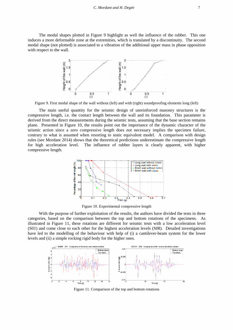
The modal shapes plotted in Figure 9 highlight as well the influence of the rubber. This one
induces a more deformable zone at the extremities, which is translated by a discontinuity. The second
modal shape (not plotted) is associated to a vibration of the additional upper mass in phase opposition
with respect to the wall.
Figure 9. First modal shape of the wall without (left) and with (right) soundproofing elements long (left)
The main useful quantity for the seismic design of unreinforced masonry structures is the
compressive length, i.e. the contact length between the wall and its foundation. This parameter is
derived from the direct measurements during the seismic tests, assuming that the base section remains
plane. Presented in Figure 10, the results point out the importance of the dynamic character of the
seismic action since a zero compressive length does not necessary implies the specimen failure,
contrary to what is assumed when resorting to static equivalent model. A comparison with design
rules (see Mordant 2014) shows that the theoretical predictions underestimate the compressive length
for high acceleration level. The influence of rubber layers is clearly apparent, with higher
compressive length.
Figure 10. Experimental compressive length
With the purpose of further exploitation of the results, the authors have divided the tests in three
categories, based on the comparison between the top and bottom rotations of the specimens. As
illustrated in Figure 11, these rotations are different for seismic tests with a low acceleration level
(S01) and come close to each other for the highest acceleration levels (S08). Detailed investigations
have led to the modelling of the behaviour with help of (i) a cantilever-beam system for the lower
levels and (ii) a simple rocking rigid body for the higher ones.
Figure 11. Comparison of the top and bottom rotations

8
Model (i) is based on the Timoshenko beam theory (Timoshenko, 1939) and also allows the
determination of a so-called frequency equation. Its expression is derived from the boundary
conditions of the system, these latter being adapted to fit with the testing configurations. This
equation is able to provide the natural frequencies of the system, depending on the geometrical,
material and mechanical properties. In this case, only these latter properties are unknown and need to
be characterized by tests or to be assessed according to standards recommendations. Therefore, Figure
12 plots the combination of elastic and shear moduli required to reach a given natural frequency
(namely the values of the undamaged situations, see Figure 8), focusing on walls without rubber.
Similar results are available for the mechanical properties of the rubber devices in Figure 13. In
comparison to (Mordant 2013a), the results have been updated to consider the rotary inertia of the
additional mass and the lever arm between the gravity centre of the mass and the wall top. Details of
the developed models and of the expressions of the frequency equation will be presented in an
upcoming contribution.
If the undamaged situation is considered, these coupled values of elastic and shear moduli can
be compared to the values suggested in normative recommendations. The conclusion is that the
suggested values are too stiff for the considered type of masonry, especially regarding the long wall.
Indeed, the recommended couple is (E = 3900 MPa and G/E = 0.4), which lies pretty much above the
drawn lines and would thus lead to overestimated values of the frequencies. Concerning the rubber
devices, the results obtained in terms of elastic modulus are in the range of proposed by the producer,
namely a compression modulus of about 10 MPa, for a Poisson ratio of 0.5.
Figure 12. Results of the frequency equation for walls without rubber devices (left: long wall, right: short wall)
Figure 13. Results of the frequency equation for walls with rubber devices (left: long wall, right: short wall)
The second model (ii) relies on the theoretical developments of Housner (Housner, 1963) and
has been extended to consider the additional upper mass and the intrinsic deformability of the
specimen, resulting in adjustments of the restitution coefficient and of the criterion defining the
initiation of the rocking motion. The results for the walls without rubber are detailed in (Mordant,
2013b) and are illustrated in Figure 14 for the short wall. A good agreement of the physical tests and
of the model is observed, except at the end of the signal. This difference can possibly be explained by
the influence of the table motion, which modifies artificially the damping through its breaking system.
Given the empirical formulation of the restitution coefficient, having a perfect correspondence is
difficult, due to its limited physical background.

C. Mordant and H. Degée 9
2 4 6 8 10 12-0.015
-0.01
-0.005
0
0.005
0.01
0.015
Time [s]
Rota
tion [-]
Short wall - S07 Comparisons of the rotation
Theoretical rotation
Measured rotation
2 4 6 8 10 12 14-0.03
-0.02
-0.01
0
0.01
0.02
0.03
Time [s]
Rota
tion [-]
Short wall - S09 Comparisons of the rotation
Theoretical rotation
Measured rotation
Figure 14. Results of the rocking model for the short wall (top: S07, bottom: S09)
SECOND EXPERIMENTAL SET
The only currently available results of the second experimental set corresponds to the exploitation of
the white noise tests and provide information about the natural frequencies and the corresponding
modal shapes. Full results are given in (Mordant 2015) while the results for the frame with T-shaped
piers are detailed hereby (Figure 15) for the first two natural frequencies. As for the first set, a
frequency drop is observed, translating the progressive damages of the specimens when the
acceleration level increases.
In Table 4, the first two experimental frequency values of the undamaged situation in both
directions are compared to results obtained with a shell finite elements model. The mechanical
properties leading to these close values are given by the coupled values [E, G/E] equal to [1287 MPa,
1/3]. These values are again lower than the recommended values given by the standards.
0 2 4 6 8 100
5
10
15
20
25
30
35
N° of the previous seismic test
Fre
quency [H
z]
Natural frequencies of the specimen with T-shaped piers (X-direction)
1st
natural frequency
2nd
natural frequency
3rd
natural frequency
0 2 4 6 8 100
5
10
15
20
25
30
35
N° of the previous seismic test
Fre
quency [H
z]
Natural frequencies of the specimen with T-shaped piers (Y-direction)
1st
natural frequency
2nd
natural frequency
3rd
natural frequency
Figure 15. Natural frequencies of the second set
Table 4. Natural frequencies of the undamaged frame with T-shaped piers
Direction Experimental values
[Hz]
Model values
[Hz]
1st frequency Perpendicular plan 5.18 5.18
1st frequency Frame plan 6.86 6.94
2nd frequency Perpendicular plan 9.71 9.51
2nd frequency Frame plan 9.19 9.51
The modal shapes in Figure 16, 17 & 18 (left) are identified on the base of the measurement
recorded by the four accelerometers fixed on the RC slab. These describe the overall response of the
specimen in the horizontal plan, assuming that the slab behaves as a rigid body. The identified modes
are a combination of translations and rotation of this rigid body. The translation component is more
important for the first and third modes, while the second one is essentially rotational and is therefore
more or less similar whatever the excitation direction. These experimental results are compared to
those provided by the numerical model, drawn in Figure 16, 17 & 18 (right). The modal shapes
correspond respectively to the first frequency perpendicular to the frame plan, the first frequency in

10
the frame plan and the second frequency. The fitting of the modal shapes shows an extremely good
agreement.
-1.5 -1 -0.5 0 0.5 1 1.5-1.5
-1
-0.5
0
0.5
1
1.5Slab - Initial position (blue) and deformation mode n°1 (red)
Figure 16. Corresponding modal shapes of the first mode perpendicular to the fame plan (left: experimental,
right: model)
-1.5 -1 -0.5 0 0.5 1 1.5-1.5
-1
-0.5
0
0.5
1
1.5Slab - Initial position (blue) and deformation mode n°1 (red)
Figure 17. Corresponding modal shapes of the first mode in the fame plan (left: experimental, right: model)
-1.5 -1 -0.5 0 0.5 1 1.5-1.5
-1
-0.5
0
0.5
1
1.5Slab - Initial position (blue) and deformation mode n°2 (red)
Figure 18. Corresponding modal shapes of the second mode (left: experimental, right: model)
CONCLUSIONS
This paper gives an overview of experimental shake table tests results on unreinforced load-bearing
clay masonry sub-structures with glued horizontal joints and empty vertical ones. Divided in two sets,
the specimens comprise four simple walls including or not soundproofing devices and two masonry
frames with T- or L-shaped piers.
The objectives of the first set were to investigate the dynamic behaviour of simple masonry
walls and to study the influence of rubber devices used for acoustic reasons. Beside the direct
exploitation of the experimental measurements, modelling of the specimens has been proposed and
leads to the following conclusions:
The natural frequencies of the masonry walls without sound-proofing elements decrease
progressively for increasing seismic intensity. This frequency drop translates a progressive
damaging of the specimens concentrated in the base mortar joint;
The presence of soundproofing devices also leads to decreasing natural frequencies of the
specimens but a beneficial influence of these devices can be identified through a more

C. Mordant and H. Degée 11
limited the frequency drop and an increased the contact length. Nevertheless, this
conclusion is mitigated by larger horizontal displacements that could become problematic at
the scale of an entire building;
The compressive length can be easily assessed. The procedure proposed by the design
standards is relevant for low acceleration level but underestimates the experimental value
for higher acceleration;
The natural frequencies can be theoretically calculated thanks to a frequency equation derived
from a Timoshenko beam theory. Such a model is relevant for the lowest seismic input
where no or very limited uplift of the base is observed. The use of such a methodology
allows a characterization of the mechanical properties of the masonry and a comparison
with the recommended standards values leads to the conclusions that the couple
elastic/shear moduli proposed by the norms is too stiff for the considered type of masonry;
Concerning the highest seismic input, a significant rocking behaviour is observed and a simple
"rigidly rocking" model allows reproducing the experimental observations with a reasonable
accuracy.
The second test series had the objectives to develop a better understanding of the seismic
response of masonry frames and to investigate the contribution of spandrels elements and walls
perpendicular to the earthquake direction. Other points of interest are the influence of torsional
effects, of the connection type between perpendicular walls and of the gravity loading cases. The
experimental test results still require further exploitation, but the dynamic properties of the specimens
(natural frequencies, modal shapes) are shown to be easily predicted thanks to a simple finite elements
model with shell elements.
Further perspectives cover the investigation of the modelling and behaviour of walls with
rubber, the extensive exploitation of the results on the second set of tests and the globalization of the
theoretical model to study entire buildings.
ACKNOWLEDGEMENTS
The research leading to these results has received funding from the European Union Seventh Framework
Programme (FP7/2007-2013) under grant agreement n° 227887, SERIES. C. Mordant also acknowledges the
F.R.I.A. for the support of his PhD. The support received from EQUALS laboratory or University of Bristol, and
in particular from Dr. M. Dietz, as well as the support of the company Wienerberger in providing the materials
are also deeply acknowledged.
REFERENCES
Degée H, Denoël V, Candeias P, Campos Costa A, Coelho E (2007) “Experimental investigation on the seismic
behaviour of North-European masonry houses”. 7° Congresso de Sismologia e Engenharia Sismica
(SISMICA), Porto, Portugal, 26-27-28 September
Eurocode 6 (2004) “Eurocode 6: Design of masonry structures – Part 1.1 : Common rules for reinforced and
unreinforced masonry structures.”
Eurocode8. (2004). “Eurocode 8 : Design of structures for earthquake resistance - Part 1 : General rules, seismic
actions and rules for buildings”.
Housner, G.W. (1963) The behaviour of inverted pendulum structures during earthquakes. Bulletin of the
Seismological Society of America, 53 2, 403-417.
Karantoni F, Lirantzaki FN (2009). “Seismic behaviour of "Simple Masonry Buildings" according to EN 1998”.
7th International Conference on Earthquake Resistant Engineering Structures, Limassol, North Cypris,
11-12-13 May
Kazemi, MT, Hoseinzadeh Asl M, Bakhshi A, Rahimzadeh Rofooei F (2010) “Shaking table study of a full-scale
single storey confined brick masonry building.” Scientia Iranica, 17(3), 184-193
Mordant, C. (2012) “Contribution to experimental tests on the seismic behaviour of masonry structural
elements.” Master-Thesis, University of Liège.
Mordant, C., Dietz, M. & Degée, H (2013a) Experimental tests on the seismic behaviour of unreinforced load-
bearing masonry structures (Paper no 243). In: Proc. Vienna Congress on Recent Advances in Earthquake
12
Engineering and Structural Dynamics 2013 (VEESD 2013), eds. C. Adam, R. Heuer & C. Schranz,
Vienna, Austria, 28-30 August 2013
Mordant, C., Dietz, M. & Degée, H. (2013b) Shaking table tests on unreinforced load-bearing masonry walls –
comparison with simple rocking models (Paper n°1238). In: Proc. 4th ECCOMAS Thematic Conference
on Computational Methods in Structural Dynamics and Earthquake Engineering (COMPDYN 2013), eds.
M. Papadrakakis, V. Papadopoulos & V. Plevris, Kos Island, Greece, 12-14 June 2013
Mordant, C., Dietz, M., Taylor, C., Plumier, A. & Degée, H. (2014) Seismic behaviour of thin-bed layered
unreinforced clay masonry shear walls including soundproofing elements, Chapter 6. In: Seismic
Evaluation and Rehabilitation of Structures, eds Alper Ilki and Mochal N. Fardis, Geotechnical,
Geological and Earthquake Engineering series Vol. 26, Springer International Publishing Switzerland
2014, 77-93
Mordant, C., Dietz, M., Taylor, C. & Degée, H. (2015) Seismic behaviour of thin-bed layered unreinforced clay
masonry frames with T- or L-shaped piers. In: Seismic Evaluation and Rehabilitation of Structures, eds
Alper Ilki and Mochal N. Fardis, Geotechnical, Geological and Earthquake Engineering series, Springer
2015. (in press)
Nakagawa T, Narafu T, Imai H et al (2012) “Collapse behaviour of a brick masonry house using a shaking table
and numerical simulation based on the extended distinct element method”, Bulletin of Earthquake
Engineering, 10:269-283
Schermer DC (2005) “Autoclaved Aerated Concrete Innovation and Development”, 4th International
Conference on Autoclaved Aerated Concrete, AAC, London, United Kingdom, September
Timoshenko, S. (1939) Théorie des vibrations, Librairie polytechnique, ed. Béranger, Ch.: Paris et Liège 1939.
Tomazevic M (1999) Earthquake-Resistant Design of Masonry Buildings, Imperial College Press, London