Embed Size (px)
Citation preview
Setup for Failover Clustering andMicrosoft Cluster Service
Update 1ESXi 5.1
vCenter Server 5.1
This document supports the version of each product listed andsupports all subsequent versions until the document isreplaced by a new edition. To check for more recent editionsof this document, see http://www.vmware.com/support/pubs.
EN-000794-00
Setup for Failover Clustering and Microsoft Cluster Service
2 VMware, Inc.
You can find the most up-to-date technical documentation on the VMware Web site at:
http://www.vmware.com/support/
The VMware Web site also provides the latest product updates.
If you have comments about this documentation, submit your feedback to:
Copyright © 2006–2012 VMware, Inc. All rights reserved. Copyright and trademark information.
VMware, Inc.3401 Hillview Ave.Palo Alto, CA 94304www.vmware.com
Contents
Setup for Failover Clustering and Microsoft Cluster Service 5Getting Started with MSCS 5Cluster Virtual Machines on One Physical Host 10Cluster Virtual Machines Across Physical Hosts 17Cluster Physical and Virtual Machines 25Use MSCS in an vSphere HA and vSphere DRS Environment 30vSphere MSCS Setup Checklist 37
Index 39
VMware, Inc. 3

Setup for Failover Clustering and Microsoft Cluster Service
4 VMware, Inc.
Setup for Failover Clustering and MicrosoftCluster Service
Setup for Failover Clustering and Microsoft Cluster Service describes the types of clusters you can implementusing virtual machines with Microsoft Cluster Service for Windows Server 2003 and Failover Clustering forWindows Server 2008. You get step-by-step instructions for each type of cluster and a checklist of clusteringrequirements and recommendations.
Unless stated otherwise, the term Microsoft Cluster Service (MSCS) applies to Microsoft Cluster Service withWindows Server 2003 and Failover Clustering with Windows Server 2008.
Setup for Failover Clustering and Microsoft Cluster Service covers ESXi and VMware® vCenter® Server.
Intended AudienceThis information is for system administrators who are familiar with VMware technology andMicrosoft Cluster Service.
NOTE This is not a guide to using Microsoft Cluster Service or Failover Clustering. Use your Microsoftdocumentation for information about installation and configuration of Microsoft Cluster Service orFailover Clustering.
Getting Started with MSCSVMware® vSphere® supports clustering using MSCS across virtual machines. Clustering virtual machinescan reduce the hardware costs of traditional high-availability clusters.
NOTE vSphere High Availability (vSphere HA) supports a clustering solution in conjunction withvCenter Server clusters. vSphere Availability describes vSphere HA functionality.
Clustering Configuration OverviewSeveral applications use clustering, including stateless applications such as Web servers, and applicationswith built-in recovery features such as database servers. You can set up MSCS clusters in severalconfigurations, depending on your environment.
A typical clustering setup includes:
n Disks that are shared between nodes. A shared disk is required as a quorum disk. In a cluster of virtualmachines across physical hosts, the shared disk must be on a Fibre Channel (FC) SAN.
n A private heartbeat network between nodes.
You can set up the shared disks and private heartbeat using one of several clustering configurations.
VMware, Inc. 5
Clustering MSCS Virtual Machines on a Single HostA cluster of MSCS virtual machines on a single host (also known as a cluster in a box) consists of clusteredvirtual machines on the same ESXi host. The virtual machines are connected to the same storage, either localor remote. This configuration protects against failures at the operating system and application level, but itdoes not protect against hardware failures.
NOTE Windows Server 2008 R2 systems support up to five nodes (virtual machines). Windows Server 2003SP2 systems support two nodes.
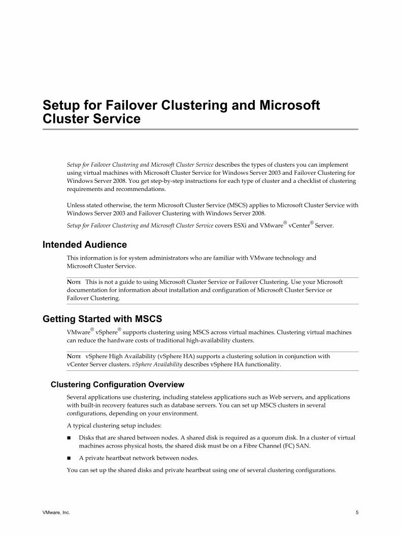
The following figure shows a cluster in a box setup.
n Two virtual machines on the same physical machine (ESXi host) run clustering software.
n The virtual machines share a private network connection for the private heartbeat and a public networkconnection.
n Each virtual machine is connected to shared storage, which can be local or on a SAN.
Figure 1. Virtual Machines Clustered on a Single Host
physical machine
virtual machineNode1
clustersoftware
virtual machineNode2
clustersoftware
storage (local or SAN)
privatenetwork
publicnetwork
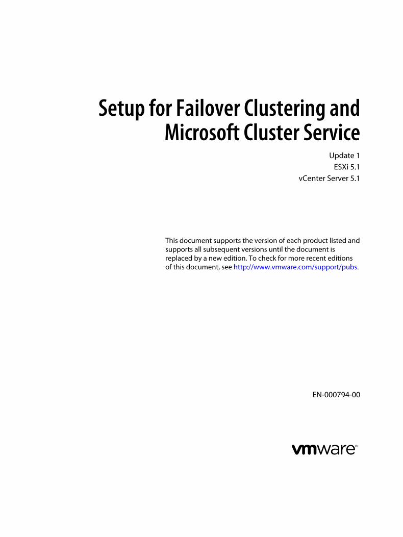
Clustering Virtual Machines Across Physical HostsA cluster of virtual machines across physical hosts (also known as a cluster across boxes) protects againstsoftware failures and hardware failures on the physical machine by placing the cluster nodes on separateESXi hosts. This configuration requires shared storage on an Fibre Channel SAN for the quorum disk.
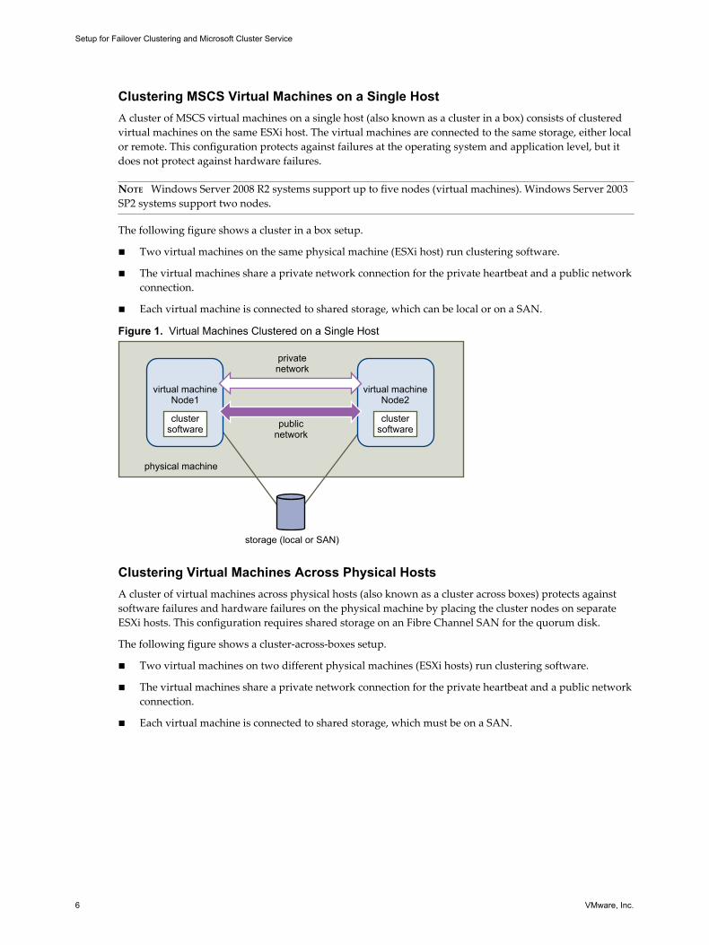
The following figure shows a cluster-across-boxes setup.
n Two virtual machines on two different physical machines (ESXi hosts) run clustering software.
n The virtual machines share a private network connection for the private heartbeat and a public networkconnection.
n Each virtual machine is connected to shared storage, which must be on a SAN.
Setup for Failover Clustering and Microsoft Cluster Service
6 VMware, Inc.
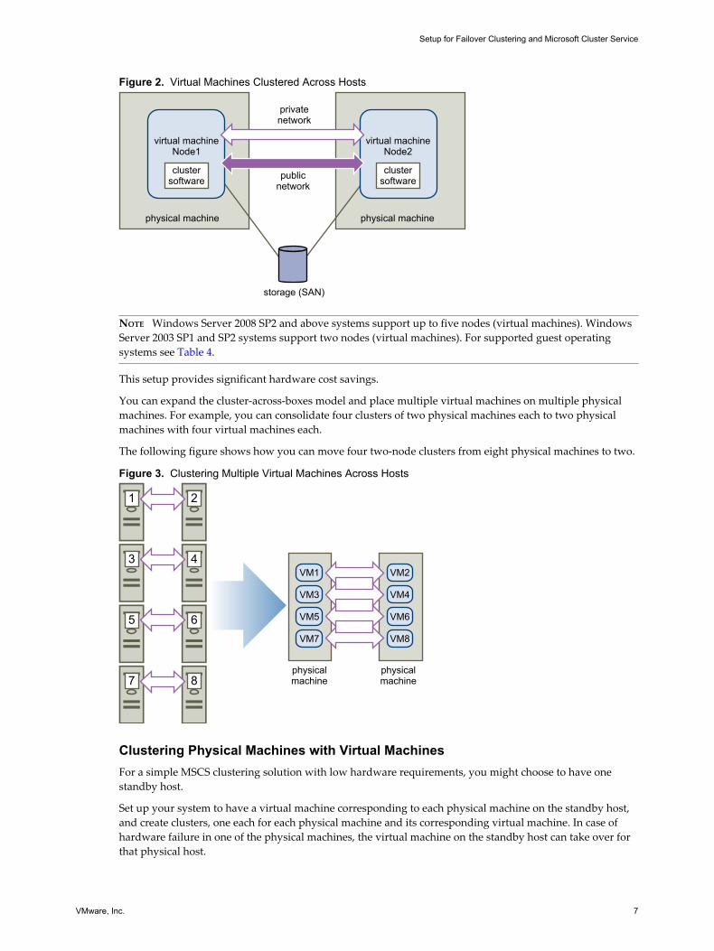
Figure 2. Virtual Machines Clustered Across Hosts
physical machine physical machine
virtual machineNode1
clustersoftware
virtual machineNode2
clustersoftware
storage (SAN)
privatenetwork
publicnetwork
NOTE Windows Server 2008 SP2 and above systems support up to five nodes (virtual machines). WindowsServer 2003 SP1 and SP2 systems support two nodes (virtual machines). For supported guest operatingsystems see Table 4.
This setup provides significant hardware cost savings.
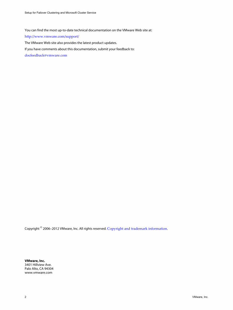
You can expand the cluster-across-boxes model and place multiple virtual machines on multiple physicalmachines. For example, you can consolidate four clusters of two physical machines each to two physicalmachines with four virtual machines each.
The following figure shows how you can move four two-node clusters from eight physical machines to two.
Figure 3. Clustering Multiple Virtual Machines Across Hosts
physicalmachine
physicalmachine
VM1
VM3
VM5
VM7
VM2
VM4
VM6
VM8
1
3
5
7
2
4
6
8
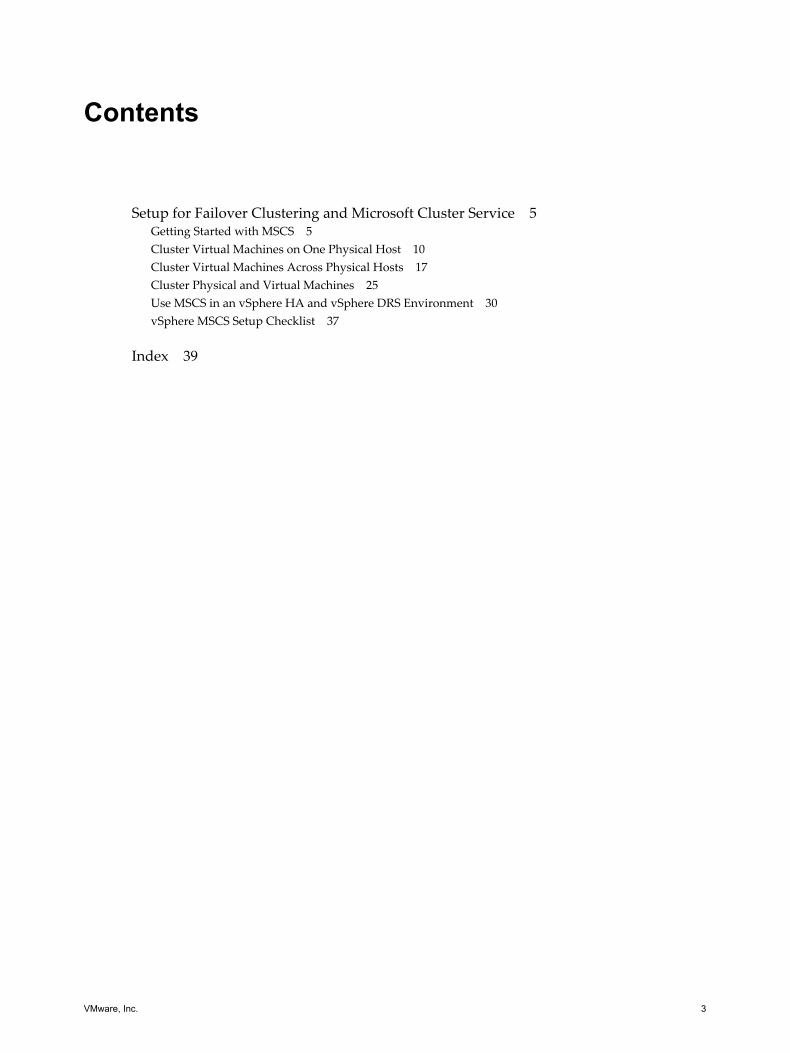
Clustering Physical Machines with Virtual MachinesFor a simple MSCS clustering solution with low hardware requirements, you might choose to have onestandby host.
Set up your system to have a virtual machine corresponding to each physical machine on the standby host,and create clusters, one each for each physical machine and its corresponding virtual machine. In case ofhardware failure in one of the physical machines, the virtual machine on the standby host can take over forthat physical host.
Setup for Failover Clustering and Microsoft Cluster Service
VMware, Inc. 7
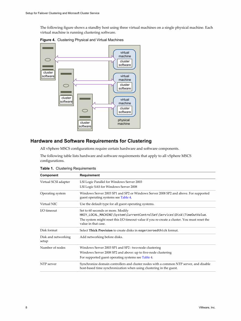
The following figure shows a standby host using three virtual machines on a single physical machine. Eachvirtual machine is running clustering software.
Figure 4. Clustering Physical and Virtual Machines
physicalmachine
virtualmachinecluster
software
virtualmachinecluster
software
virtualmachinecluster
software
clustersoftware
clustersoftware
clustersoftware
Hardware and Software Requirements for ClusteringAll vSphere MSCS configurations require certain hardware and software components.
The following table lists hardware and software requirements that apply to all vSphere MSCSconfigurations.
Table 1. Clustering Requirements
Component Requirement
Virtual SCSI adapter LSI Logic Parallel for Windows Server 2003LSI Logic SAS for Windows Server 2008
Operating system Windows Server 2003 SP1 and SP2 or Windows Server 2008 SP2 and above. For supportedguest operating systems see Table 4.
Virtual NIC Use the default type for all guest operating systems.
I/O timeout Set to 60 seconds or more. ModifyHKEY_LOCAL_MACHINE\System\CurrentControlSet\Services\Disk\TimeOutValue.The system might reset this I/O timeout value if you re-create a cluster. You must reset thevalue in that case.
Disk format Select Thick Provision to create disks in eagerzeroedthick format.
Disk and networkingsetup
Add networking before disks.
Number of nodes Windows Server 2003 SP1 and SP2 : two-node clusteringWindows Server 2008 SP2 and above: up to five-node clusteringFor supported guest operating systems see Table 4.
NTP server Synchronize domain controllers and cluster nodes with a common NTP server, and disablehost-based time synchronization when using clustering in the guest.
Setup for Failover Clustering and Microsoft Cluster Service
8 VMware, Inc.
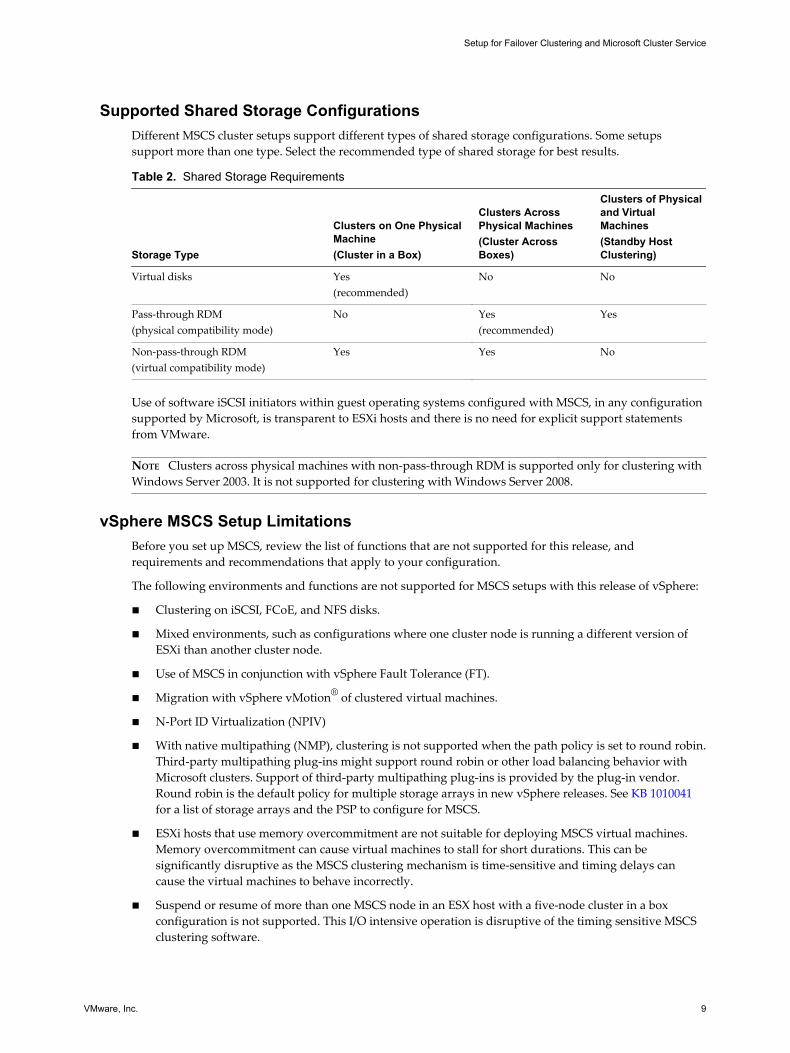
Supported Shared Storage ConfigurationsDifferent MSCS cluster setups support different types of shared storage configurations. Some setupssupport more than one type. Select the recommended type of shared storage for best results.
Table 2. Shared Storage Requirements
Storage Type
Clusters on One PhysicalMachine(Cluster in a Box)
Clusters AcrossPhysical Machines(Cluster AcrossBoxes)
Clusters of Physicaland VirtualMachines(Standby HostClustering)
Virtual disks Yes(recommended)
No No
Pass-through RDM(physical compatibility mode)
No Yes(recommended)
Yes
Non-pass-through RDM(virtual compatibility mode)
Yes Yes No
Use of software iSCSI initiators within guest operating systems configured with MSCS, in any configurationsupported by Microsoft, is transparent to ESXi hosts and there is no need for explicit support statementsfrom VMware.
NOTE Clusters across physical machines with non-pass-through RDM is supported only for clustering withWindows Server 2003. It is not supported for clustering with Windows Server 2008.
vSphere MSCS Setup LimitationsBefore you set up MSCS, review the list of functions that are not supported for this release, andrequirements and recommendations that apply to your configuration.
The following environments and functions are not supported for MSCS setups with this release of vSphere:
n Clustering on iSCSI, FCoE, and NFS disks.
n Mixed environments, such as configurations where one cluster node is running a different version ofESXi than another cluster node.
n Use of MSCS in conjunction with vSphere Fault Tolerance (FT).
n Migration with vSphere vMotion® of clustered virtual machines.
n N-Port ID Virtualization (NPIV)
n With native multipathing (NMP), clustering is not supported when the path policy is set to round robin.Third-party multipathing plug-ins might support round robin or other load balancing behavior withMicrosoft clusters. Support of third-party multipathing plug-ins is provided by the plug-in vendor.Round robin is the default policy for multiple storage arrays in new vSphere releases. See KB 1010041for a list of storage arrays and the PSP to configure for MSCS.
n ESXi hosts that use memory overcommitment are not suitable for deploying MSCS virtual machines.Memory overcommitment can cause virtual machines to stall for short durations. This can besignificantly disruptive as the MSCS clustering mechanism is time-sensitive and timing delays cancause the virtual machines to behave incorrectly.
n Suspend or resume of more than one MSCS node in an ESX host with a five-node cluster in a boxconfiguration is not supported. This I/O intensive operation is disruptive of the timing sensitive MSCSclustering software.
Setup for Failover Clustering and Microsoft Cluster Service
VMware, Inc. 9
MSCS and Booting from a SANYou can put the boot disk of a virtual machine on a SAN-based VMFS volume.
Booting from a SAN is complex. Problems that you encounter in physical environments extend to virtualenvironments. For general information about booting from a SAN, see the vSphere Storage documentation.
Follow these guidelines when you place the boot disk of a virtual machine on a SAN-based VMFS volume:
n Consider the best practices for boot-from-SAN that Microsoft publishes in the following knowledgebase article: http://support.microsoft.com/kb/305547/en-us.
n Use StorPort LSI Logic drivers instead of SCSIport drivers when running Microsoft Cluster Service forWindows Server 2003 or 2008 guest operating systems.
n Test clustered configurations in different failover scenarios before you put them into productionenvironments.
Setting up Clustered Continuous Replication or Database Availability Groupswith Exchange 2010
You can set up Clustered Continuous Replication (CCR) with Exchange 2007 or Database AvailabilityGroups (DAG) with Exchange 2010 in your vSphere environment.
When working in a vSphere environment:
n Use virtual machines instead of physical machines as the cluster components.
n If the boot disks of the CCR or DAG virtual machines are on a SAN, see “MSCS and Booting from aSAN,” on page 10.
For more information, see Microsoft’s documentation for CCR or DAG on the Microsoft Web site.
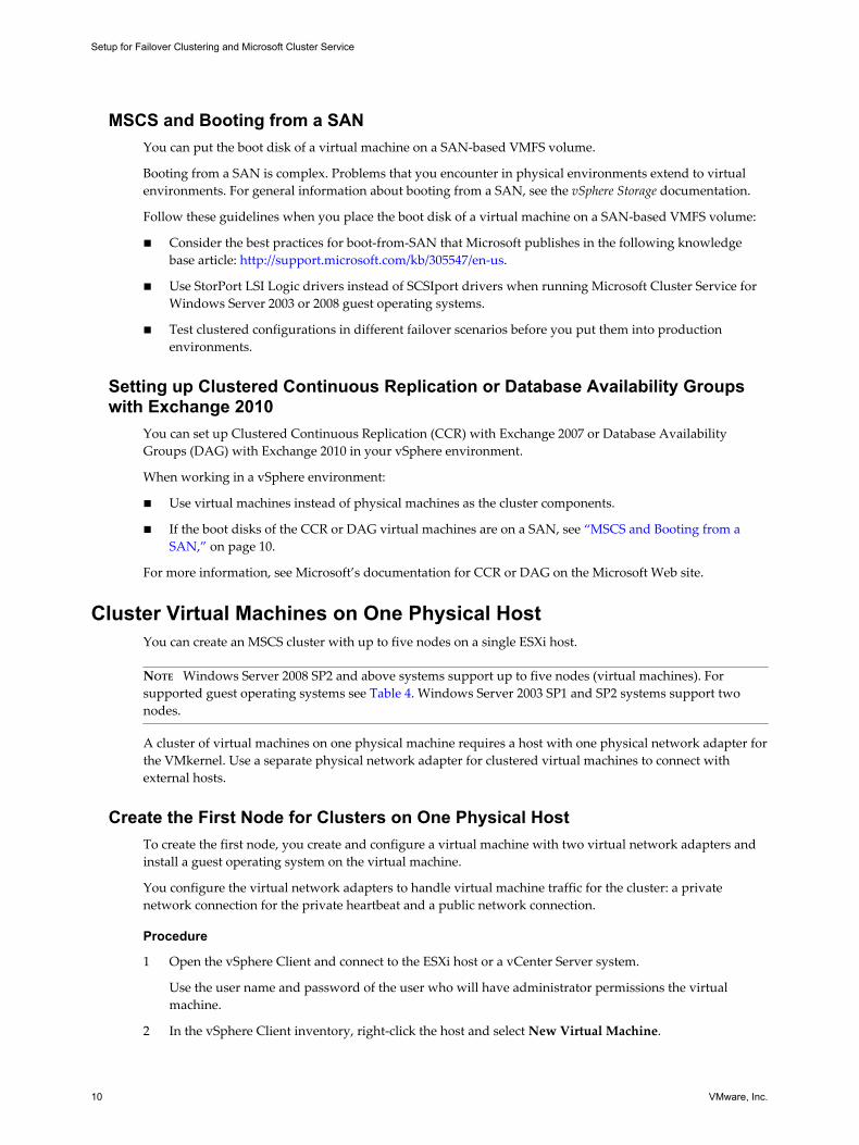
Cluster Virtual Machines on One Physical HostYou can create an MSCS cluster with up to five nodes on a single ESXi host.
NOTE Windows Server 2008 SP2 and above systems support up to five nodes (virtual machines). Forsupported guest operating systems see Table 4. Windows Server 2003 SP1 and SP2 systems support twonodes.
A cluster of virtual machines on one physical machine requires a host with one physical network adapter forthe VMkernel. Use a separate physical network adapter for clustered virtual machines to connect withexternal hosts.
Create the First Node for Clusters on One Physical HostTo create the first node, you create and configure a virtual machine with two virtual network adapters andinstall a guest operating system on the virtual machine.
You configure the virtual network adapters to handle virtual machine traffic for the cluster: a privatenetwork connection for the private heartbeat and a public network connection.
Procedure
1 Open the vSphere Client and connect to the ESXi host or a vCenter Server system.
Use the user name and password of the user who will have administrator permissions the virtualmachine.
2 In the vSphere Client inventory, right-click the host and select New Virtual Machine.
Setup for Failover Clustering and Microsoft Cluster Service
10 VMware, Inc.
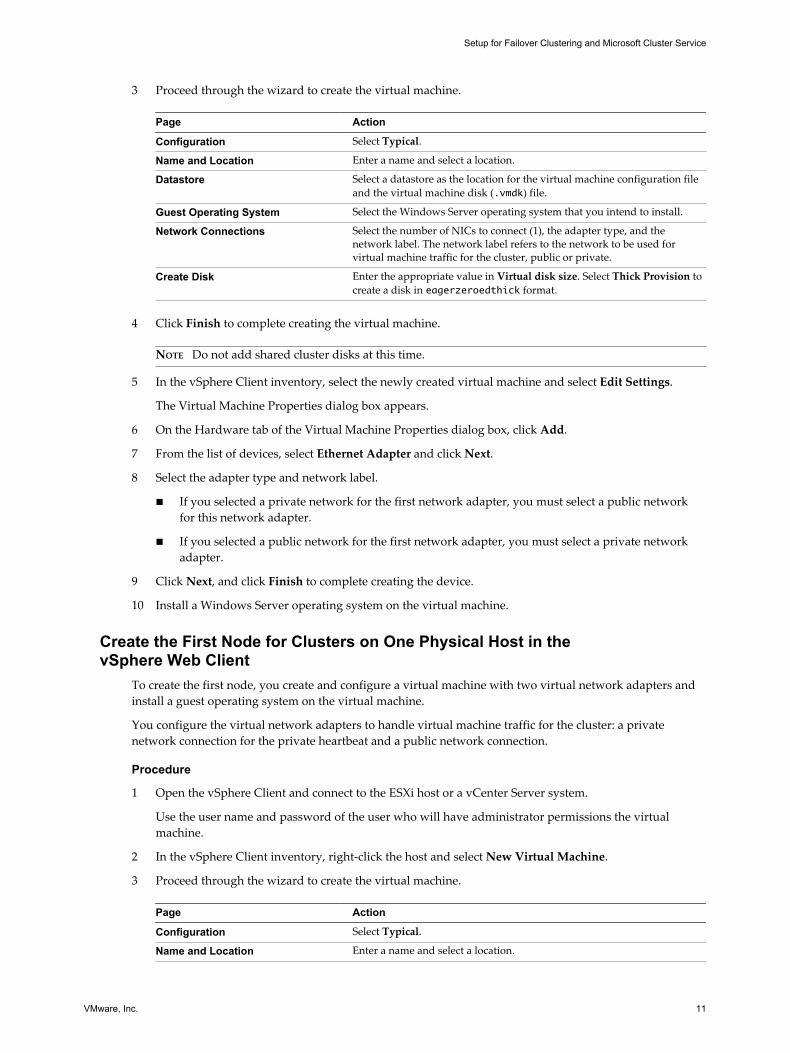
3 Proceed through the wizard to create the virtual machine.
Page Action
Configuration Select Typical.
Name and Location Enter a name and select a location.
Datastore Select a datastore as the location for the virtual machine configuration fileand the virtual machine disk (.vmdk) file.
Guest Operating System Select the Windows Server operating system that you intend to install.
Network Connections Select the number of NICs to connect (1), the adapter type, and thenetwork label. The network label refers to the network to be used forvirtual machine traffic for the cluster, public or private.
Create Disk Enter the appropriate value in Virtual disk size. Select Thick Provision tocreate a disk in eagerzeroedthick format.
4 Click Finish to complete creating the virtual machine.
NOTE Do not add shared cluster disks at this time.
5 In the vSphere Client inventory, select the newly created virtual machine and select Edit Settings.
The Virtual Machine Properties dialog box appears.
6 On the Hardware tab of the Virtual Machine Properties dialog box, click Add.
7 From the list of devices, select Ethernet Adapter and click Next.
8 Select the adapter type and network label.
n If you selected a private network for the first network adapter, you must select a public networkfor this network adapter.
n If you selected a public network for the first network adapter, you must select a private networkadapter.
9 Click Next, and click Finish to complete creating the device.
10 Install a Windows Server operating system on the virtual machine.
Create the First Node for Clusters on One Physical Host in thevSphere Web Client
To create the first node, you create and configure a virtual machine with two virtual network adapters andinstall a guest operating system on the virtual machine.
You configure the virtual network adapters to handle virtual machine traffic for the cluster: a privatenetwork connection for the private heartbeat and a public network connection.
Procedure
1 Open the vSphere Client and connect to the ESXi host or a vCenter Server system.
Use the user name and password of the user who will have administrator permissions the virtualmachine.
2 In the vSphere Client inventory, right-click the host and select New Virtual Machine.
3 Proceed through the wizard to create the virtual machine.
Page Action
Configuration Select Typical.
Name and Location Enter a name and select a location.
Setup for Failover Clustering and Microsoft Cluster Service
VMware, Inc. 11
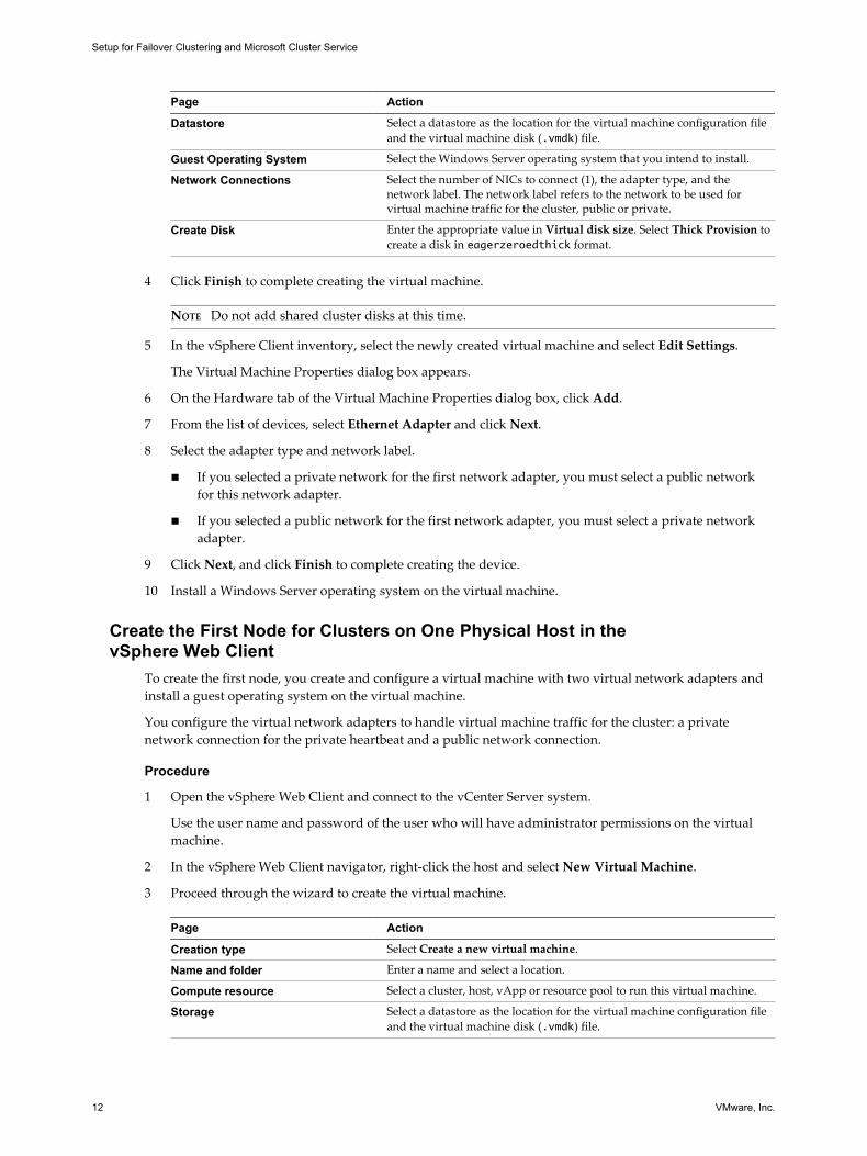
Page Action
Datastore Select a datastore as the location for the virtual machine configuration fileand the virtual machine disk (.vmdk) file.
Guest Operating System Select the Windows Server operating system that you intend to install.
Network Connections Select the number of NICs to connect (1), the adapter type, and thenetwork label. The network label refers to the network to be used forvirtual machine traffic for the cluster, public or private.
Create Disk Enter the appropriate value in Virtual disk size. Select Thick Provision tocreate a disk in eagerzeroedthick format.
4 Click Finish to complete creating the virtual machine.
NOTE Do not add shared cluster disks at this time.
5 In the vSphere Client inventory, select the newly created virtual machine and select Edit Settings.
The Virtual Machine Properties dialog box appears.
6 On the Hardware tab of the Virtual Machine Properties dialog box, click Add.
7 From the list of devices, select Ethernet Adapter and click Next.
8 Select the adapter type and network label.
n If you selected a private network for the first network adapter, you must select a public networkfor this network adapter.
n If you selected a public network for the first network adapter, you must select a private networkadapter.
9 Click Next, and click Finish to complete creating the device.
10 Install a Windows Server operating system on the virtual machine.
Create the First Node for Clusters on One Physical Host in thevSphere Web Client
To create the first node, you create and configure a virtual machine with two virtual network adapters andinstall a guest operating system on the virtual machine.
You configure the virtual network adapters to handle virtual machine traffic for the cluster: a privatenetwork connection for the private heartbeat and a public network connection.
Procedure
1 Open the vSphere Web Client and connect to the vCenter Server system.
Use the user name and password of the user who will have administrator permissions on the virtualmachine.
2 In the vSphere Web Client navigator, right-click the host and select New Virtual Machine.
3 Proceed through the wizard to create the virtual machine.
Page Action
Creation type Select Create a new virtual machine.
Name and folder Enter a name and select a location.
Compute resource Select a cluster, host, vApp or resource pool to run this virtual machine.
Storage Select a datastore as the location for the virtual machine configuration fileand the virtual machine disk (.vmdk) file.
Setup for Failover Clustering and Microsoft Cluster Service
12 VMware, Inc.
Page Action
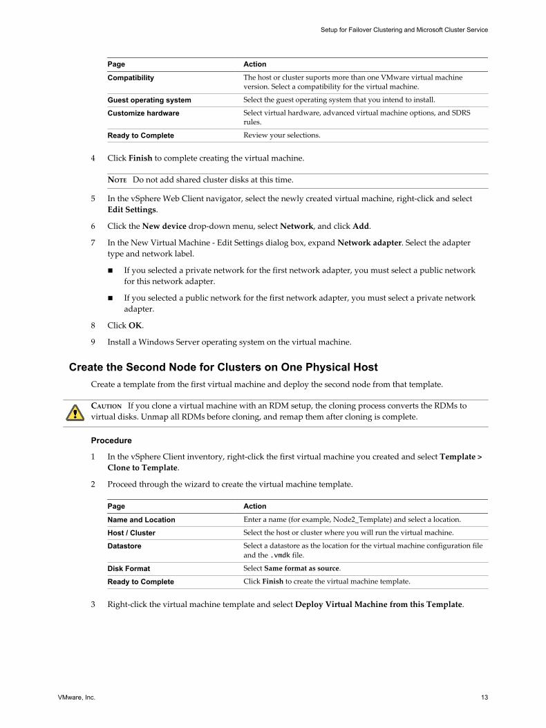
Compatibility The host or cluster suports more than one VMware virtual machineversion. Select a compatibility for the virtual machine.
Guest operating system Select the guest operating system that you intend to install.
Customize hardware Select virtual hardware, advanced virtual machine options, and SDRSrules.
Ready to Complete Review your selections.
4 Click Finish to complete creating the virtual machine.
NOTE Do not add shared cluster disks at this time.
5 In the vSphere Web Client navigator, select the newly created virtual machine, right-click and selectEdit Settings.
6 Click the New device drop-down menu, select Network, and click Add.
7 In the New Virtual Machine - Edit Settings dialog box, expand Network adapter. Select the adaptertype and network label.
n If you selected a private network for the first network adapter, you must select a public networkfor this network adapter.
n If you selected a public network for the first network adapter, you must select a private networkadapter.
8 Click OK.
9 Install a Windows Server operating system on the virtual machine.
Create the Second Node for Clusters on One Physical HostCreate a template from the first virtual machine and deploy the second node from that template.
CAUTION If you clone a virtual machine with an RDM setup, the cloning process converts the RDMs tovirtual disks. Unmap all RDMs before cloning, and remap them after cloning is complete.
Procedure
1 In the vSphere Client inventory, right-click the first virtual machine you created and select Template >Clone to Template.
2 Proceed through the wizard to create the virtual machine template.
Page Action
Name and Location Enter a name (for example, Node2_Template) and select a location.
Host / Cluster Select the host or cluster where you will run the virtual machine.
Datastore Select a datastore as the location for the virtual machine configuration fileand the .vmdk file.
Disk Format Select Same format as source.
Ready to Complete Click Finish to create the virtual machine template.
3 Right-click the virtual machine template and select Deploy Virtual Machine from this Template.
Setup for Failover Clustering and Microsoft Cluster Service
VMware, Inc. 13
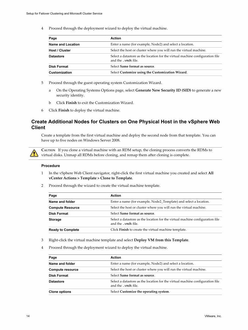
4 Proceed through the deployment wizard to deploy the virtual machine.
Page Action
Name and Location Enter a name (for example, Node2) and select a location.
Host / Cluster Select the host or cluster where you will run the virtual machine.
Datastore Select a datastore as the location for the virtual machine configuration fileand the .vmdk file.
Disk Format Select Same format as source.
Customization Select Customize using the Customization Wizard.
5 Proceed through the guest operating system Customization Wizard.
a On the Operating Systems Options page, select Generate New Security ID (SID) to generate a newsecurity identity.
b Click Finish to exit the Customization Wizard.
6 Click Finish to deploy the virtual machine.
Create Additional Nodes for Clusters on One Physical Host in the vSphere WebClient
Create a template from the first virtual machine and deploy the second node from that template. You canhave up to five nodes on Windows Server 2008.
CAUTION If you clone a virtual machine with an RDM setup, the cloning process converts the RDMs tovirtual disks. Unmap all RDMs before cloning, and remap them after cloning is complete.
Procedure
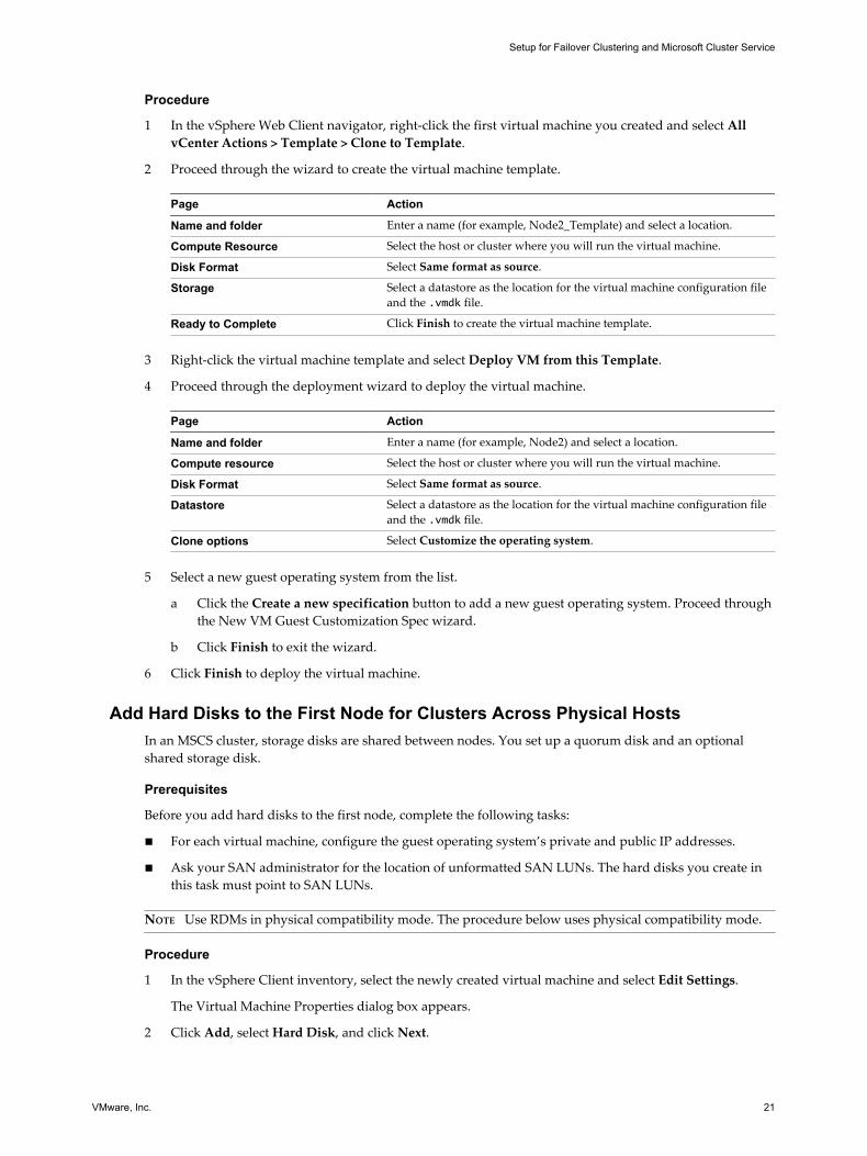
1 In the vSphere Web Client navigator, right-click the first virtual machine you created and select AllvCenter Actions > Template > Clone to Template.
2 Proceed through the wizard to create the virtual machine template.
Page Action
Name and folder Enter a name (for example, Node2_Template) and select a location.
Compute Resource Select the host or cluster where you will run the virtual machine.
Disk Format Select Same format as source.
Storage Select a datastore as the location for the virtual machine configuration fileand the .vmdk file.
Ready to Complete Click Finish to create the virtual machine template.
3 Right-click the virtual machine template and select Deploy VM from this Template.
4 Proceed through the deployment wizard to deploy the virtual machine.
Page Action
Name and folder Enter a name (for example, Node2) and select a location.
Compute resource Select the host or cluster where you will run the virtual machine.
Disk Format Select Same format as source.
Datastore Select a datastore as the location for the virtual machine configuration fileand the .vmdk file.
Clone options Select Customize the operating system.
Setup for Failover Clustering and Microsoft Cluster Service
14 VMware, Inc.
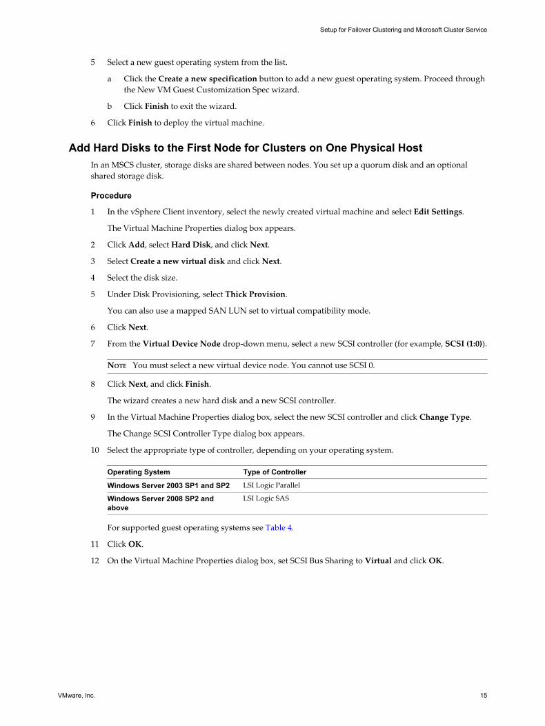
5 Select a new guest operating system from the list.
a Click the Create a new specification button to add a new guest operating system. Proceed throughthe New VM Guest Customization Spec wizard.
b Click Finish to exit the wizard.
6 Click Finish to deploy the virtual machine.
Add Hard Disks to the First Node for Clusters on One Physical HostIn an MSCS cluster, storage disks are shared between nodes. You set up a quorum disk and an optionalshared storage disk.
Procedure
1 In the vSphere Client inventory, select the newly created virtual machine and select Edit Settings.
The Virtual Machine Properties dialog box appears.
2 Click Add, select Hard Disk, and click Next.
3 Select Create a new virtual disk and click Next.
4 Select the disk size.
5 Under Disk Provisioning, select Thick Provision.
You can also use a mapped SAN LUN set to virtual compatibility mode.
6 Click Next.
7 From the Virtual Device Node drop-down menu, select a new SCSI controller (for example, SCSI (1:0)).
NOTE You must select a new virtual device node. You cannot use SCSI 0.
8 Click Next, and click Finish.
The wizard creates a new hard disk and a new SCSI controller.
9 In the Virtual Machine Properties dialog box, select the new SCSI controller and click Change Type.
The Change SCSI Controller Type dialog box appears.
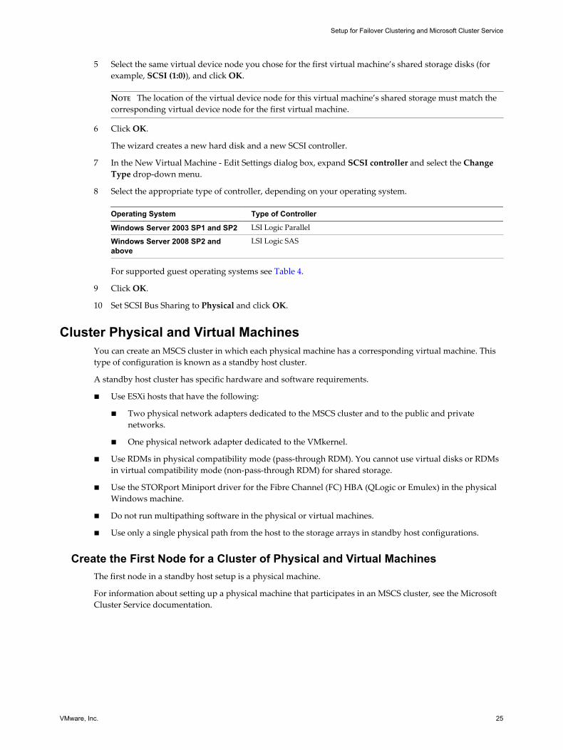
10 Select the appropriate type of controller, depending on your operating system.
Operating System Type of Controller
Windows Server 2003 SP1 and SP2 LSI Logic Parallel
Windows Server 2008 SP2 andabove
LSI Logic SAS
For supported guest operating systems see Table 4.
11 Click OK.
12 On the Virtual Machine Properties dialog box, set SCSI Bus Sharing to Virtual and click OK.
Setup for Failover Clustering and Microsoft Cluster Service
VMware, Inc. 15
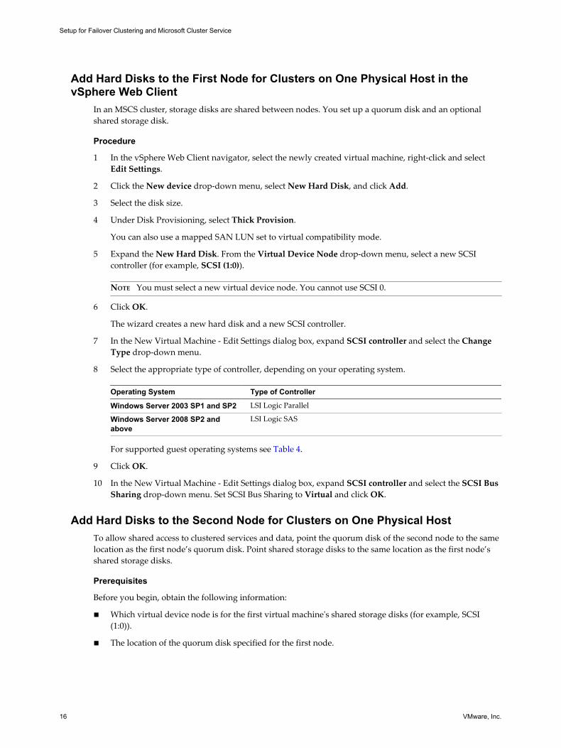
Add Hard Disks to the First Node for Clusters on One Physical Host in thevSphere Web Client
In an MSCS cluster, storage disks are shared between nodes. You set up a quorum disk and an optionalshared storage disk.
Procedure
1 In the vSphere Web Client navigator, select the newly created virtual machine, right-click and selectEdit Settings.
2 Click the New device drop-down menu, select New Hard Disk, and click Add.
3 Select the disk size.
4 Under Disk Provisioning, select Thick Provision.
You can also use a mapped SAN LUN set to virtual compatibility mode.
5 Expand the New Hard Disk. From the Virtual Device Node drop-down menu, select a new SCSIcontroller (for example, SCSI (1:0)).
NOTE You must select a new virtual device node. You cannot use SCSI 0.
6 Click OK.
The wizard creates a new hard disk and a new SCSI controller.
7 In the New Virtual Machine - Edit Settings dialog box, expand SCSI controller and select the ChangeType drop-down menu.
8 Select the appropriate type of controller, depending on your operating system.
Operating System Type of Controller
Windows Server 2003 SP1 and SP2 LSI Logic Parallel
Windows Server 2008 SP2 andabove
LSI Logic SAS
For supported guest operating systems see Table 4.
9 Click OK.
10 In the New Virtual Machine - Edit Settings dialog box, expand SCSI controller and select the SCSI BusSharing drop-down menu. Set SCSI Bus Sharing to Virtual and click OK.
Add Hard Disks to the Second Node for Clusters on One Physical HostTo allow shared access to clustered services and data, point the quorum disk of the second node to the samelocation as the first node’s quorum disk. Point shared storage disks to the same location as the first node’sshared storage disks.
Prerequisites
Before you begin, obtain the following information:
n Which virtual device node is for the first virtual machine's shared storage disks (for example, SCSI(1:0)).
n The location of the quorum disk specified for the first node.
Setup for Failover Clustering and Microsoft Cluster Service
16 VMware, Inc.
Procedure
1 In the vSphere Client inventory, select the second virtual machine that you created and select EditSettings.
The Virtual Machine Properties dialog box appears.
2 Click Add, select Hard Disk, and click Next.
3 Select Use an existing virtual disk and click Next.
4 Select the same virtual device node you chose for the first virtual machine’s shared storage disks (forexample, SCSI (1:0)), and click Next.
NOTE The location of the virtual device node for this virtual machine’s shared storage must match thecorresponding virtual device node for the first virtual machine.
5 In Disk File Path, browse to the location of the quorum disk specified for the first node.
Add Hard Disks to Additional Nodes for Clusters on One Physical Host in thevSphere Web Client
To allow shared access to clustered services and data, point the quorum disk of the second node to the samelocation as the first node’s quorum disk. Point shared storage disks to the same location as the first node’sshared storage disks.
Prerequisites
Before you begin, obtain the following information:
n Which virtual device node is for the first virtual machine's shared storage disks (for example, SCSI(1:0)).
n The location of the quorum disk specified for the first node.
Procedure
1 In the vSphere Web Client navigator, select the newly created virtual machine, right-click and selectEdit Settings.
2 Click the New device drop-down menu, select Existing Hard Disk, and click Add.
3 Select the same virtual device node you chose for the first virtual machine’s shared storage disks (forexample, SCSI (1:0)), and click OK.
NOTE The location of the virtual device node for this virtual machine’s shared storage must match thecorresponding virtual device node for the first virtual machine.
4 In Disk File Path, browse to the location of the quorum disk specified for the first node.
Cluster Virtual Machines Across Physical HostsYou can create a MSCS cluster that consists of two or more virtual machines on two ESXi or more hosts.
A cluster across physical hosts requires specific hardware and software.
n ESXi hosts that have the following:
n Two physical network adapters dedicated to the MSCS cluster and to the public and privatenetworks.
n One physical network adapter dedicated to the VMkernel.
n Fibre Channel (FC) SAN. Shared storage must be on an FC SAN.
Setup for Failover Clustering and Microsoft Cluster Service
VMware, Inc. 17
n RDM in physical compatibility (pass-through) or virtual compatibility (non-pass-through) mode.VMware recommends physical compatibility mode. The cluster cannot use virtual disks for sharedstorage.
Failover clustering with Windows Server 2008 is not supported with virtual compatibility mode (non-pass-through) RDMs.
Create the First Node for MSCS Clusters Across Physical HostsTo create the first node, you create and configure a virtual machine with two virtual network adapters andinstall a guest operating system on the virtual machine.
You configure the virtual network adapters to handle virtual machine traffic for the cluster: a privatenetwork connection for the private heartbeat and a public network connection.
Procedure
1 Open the vSphere Client and connect to the ESXi host or a vCenter Server system.
Use the user name and password of the user who will have administrator permissions the virtualmachine.
2 In the vSphere Client inventory, right-click the host and select New Virtual Machine.
3 Proceed through the wizard to create the virtual machine.
Page Action
Configuration Select Typical.
Name and Location Enter a name and select a location.
Datastore Select a datastore as the location for the virtual machine configuration fileand the virtual machine disk (.vmdk) file.
Guest Operating System Select the Windows Server operating system that you intend to install.
Network Connections Select the number of NICs to connect (1), the adapter type, and thenetwork label. The network label refers to the network to be used forvirtual machine traffic for the cluster, public or private.
Create Disk Enter the appropriate value in Virtual disk size. Select Thick Provision tocreate a disk in eagerzeroedthick format.
4 Click Finish to complete creating the virtual machine.
NOTE Do not add shared cluster disks at this time.
5 In the vSphere Client inventory, select the newly created virtual machine and select Edit Settings.
The Virtual Machine Properties dialog box appears.
6 On the Hardware tab of the Virtual Machine Properties dialog box, click Add.
7 From the list of devices, select Ethernet Adapter and click Next.
8 Select the adapter type and network label.
n If you selected a private network for the first network adapter, you must select a public networkfor this network adapter.
n If you selected a public network for the first network adapter, you must select a private networkadapter.
9 Click Next, and click Finish to complete creating the device.
10 Install a Windows Server operating system on the virtual machine.
Setup for Failover Clustering and Microsoft Cluster Service
18 VMware, Inc.
Create the First Node for MSCS Clusters Across Physical Hosts in thevSphere Web Client
To create the first node, you create and configure a virtual machine with two virtual network adapters andinstall a guest operating system on the virtual machine.
You configure the virtual network adapters to handle virtual machine traffic for the cluster: a privatenetwork connection for the private heartbeat and a public network connection.
Procedure
1 Open the vSphere Web Client and connect to the vCenter Server system.
Use the user name and password of the user who will have administrator permissions on the virtualmachine.
2 In the vSphere Web Client navigator, right-click the host and select New Virtual Machine.
3 Proceed through the wizard to create the virtual machine.
Page Action
Creation type Select Create a new virtual machine.
Name and folder Enter a name and select a location.
Compute resource Select a cluster, host, vApp or resource pool to run this virtual machine.
Storage Select a datastore as the location for the virtual machine configuration fileand the virtual machine disk (.vmdk) file.
Compatibility The host or cluster suports more than one VMware virtual machineversion. Select a compatibility for the virtual machine.
Guest operating system Select the guest operating system that you intend to install.
Customize hardware Select virtual hardware, advanced virtual machine options, and SDRSrules.
Ready to Complete Review your selections.
4 Click Finish to complete creating the virtual machine.
NOTE Do not add shared cluster disks at this time.
5 In the vSphere Web Client navigator, select the newly created virtual machine, right-click and selectEdit Settings.
6 Click the New device drop-down menu, select Network, and click Add.
7 In the New Virtual Machine - Edit Settings dialog box, expand Network adapter. Select the adaptertype and network label.
n If you selected a private network for the first network adapter, you must select a public networkfor this network adapter.
n If you selected a public network for the first network adapter, you must select a private networkadapter.
8 Click OK.
9 Install a Windows Server operating system on the virtual machine.
Setup for Failover Clustering and Microsoft Cluster Service
VMware, Inc. 19
Create the Second Node for Clusters Across Physical HostsTo create the second node in a cluster of virtual machines across physical hosts, you create a template of thefirst virtual machine and use it to deploy a second virtual machine onto a second ESXi host.
CAUTION If you clone a virtual machine with an RDM setup, the cloning process converts the RDMs tovirtual disks. Unmap all RDMs before cloning, and remap them after cloning is complete.
Procedure
1 In the vSphere Client inventory, right-click the first virtual machine you created and select Template >Clone to Template.
2 Proceed through the wizard to create the virtual machine template.
Page Action
Name and Location Enter a name and select a location.
Host or Cluster Select the second host for the cluster setup.
Resource Partition Select the resource pool for the virtual machine, or select the host if noresource pools exist.
Datastore Select a datastore as the location for the virtual machine configuration fileand the .vmdk file.
Ready to Complete Click OK to create the virtual machine template.
3 Right-click the virtual machine template and select Deploy Virtual Machine from this Template.
4 Proceed through the deployment wizard to deploy the virtual machine.
Page Action
Name and Location Enter a name (for example, Node2) and select a location.
Host / Cluster Select the host or cluster where you will run the virtual machine.
Datastore Select a datastore as the location for the virtual machine configuration fileand the .vmdk file.
Disk Format Select Same format as source.
Customization Select Customize using the Customization Wizard.
5 Proceed through the guest operating system Customization Wizard.
a On the Operating Systems Options page, select Generate New Security ID (SID) to generate a newsecurity identity.
b Click Finish to exit the Customization Wizard.
6 Click Finish to deploy the virtual machine.
Create Additional Nodes for Clusters Across Physical Hosts in the vSphereWeb Client
To create additional nodes in a cluster of virtual machines across physical hosts, you create a template of thefirst virtual machine and use it to deploy additional virtual machines onto another ESXi host.
CAUTION If you clone a virtual machine with an RDM setup, the cloning process converts the RDMs tovirtual disks. Unmap all RDMs before cloning, and remap them after cloning is complete.
Setup for Failover Clustering and Microsoft Cluster Service
20 VMware, Inc.
Procedure
1 In the vSphere Web Client navigator, right-click the first virtual machine you created and select AllvCenter Actions > Template > Clone to Template.
2 Proceed through the wizard to create the virtual machine template.
Page Action
Name and folder Enter a name (for example, Node2_Template) and select a location.
Compute Resource Select the host or cluster where you will run the virtual machine.
Disk Format Select Same format as source.
Storage Select a datastore as the location for the virtual machine configuration fileand the .vmdk file.
Ready to Complete Click Finish to create the virtual machine template.
3 Right-click the virtual machine template and select Deploy VM from this Template.
4 Proceed through the deployment wizard to deploy the virtual machine.
Page Action
Name and folder Enter a name (for example, Node2) and select a location.
Compute resource Select the host or cluster where you will run the virtual machine.
Disk Format Select Same format as source.
Datastore Select a datastore as the location for the virtual machine configuration fileand the .vmdk file.
Clone options Select Customize the operating system.
5 Select a new guest operating system from the list.
a Click the Create a new specification button to add a new guest operating system. Proceed throughthe New VM Guest Customization Spec wizard.
b Click Finish to exit the wizard.
6 Click Finish to deploy the virtual machine.
Add Hard Disks to the First Node for Clusters Across Physical HostsIn an MSCS cluster, storage disks are shared between nodes. You set up a quorum disk and an optionalshared storage disk.
Prerequisites
Before you add hard disks to the first node, complete the following tasks:
n For each virtual machine, configure the guest operating system’s private and public IP addresses.
n Ask your SAN administrator for the location of unformatted SAN LUNs. The hard disks you create inthis task must point to SAN LUNs.
NOTE Use RDMs in physical compatibility mode. The procedure below uses physical compatibility mode.
Procedure
1 In the vSphere Client inventory, select the newly created virtual machine and select Edit Settings.
The Virtual Machine Properties dialog box appears.
2 Click Add, select Hard Disk, and click Next.
Setup for Failover Clustering and Microsoft Cluster Service
VMware, Inc. 21
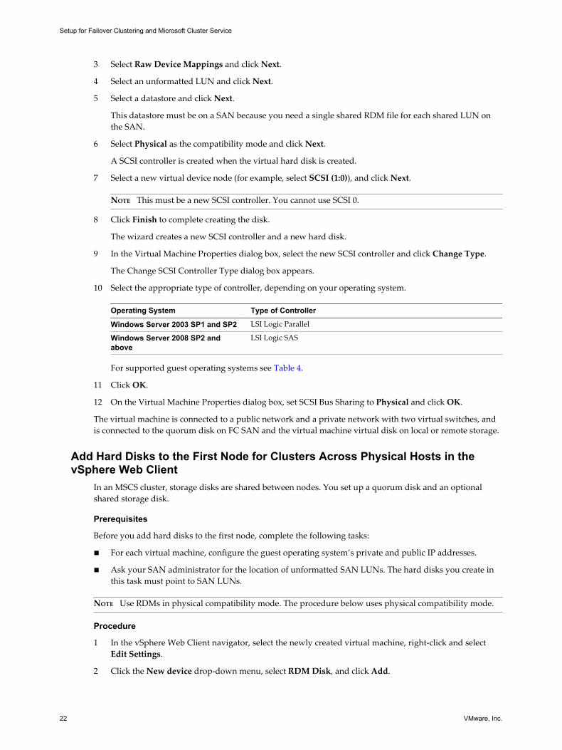
3 Select Raw Device Mappings and click Next.
4 Select an unformatted LUN and click Next.
5 Select a datastore and click Next.
This datastore must be on a SAN because you need a single shared RDM file for each shared LUN onthe SAN.
6 Select Physical as the compatibility mode and click Next.
A SCSI controller is created when the virtual hard disk is created.
7 Select a new virtual device node (for example, select SCSI (1:0)), and click Next.
NOTE This must be a new SCSI controller. You cannot use SCSI 0.
8 Click Finish to complete creating the disk.
The wizard creates a new SCSI controller and a new hard disk.
9 In the Virtual Machine Properties dialog box, select the new SCSI controller and click Change Type.
The Change SCSI Controller Type dialog box appears.
10 Select the appropriate type of controller, depending on your operating system.
Operating System Type of Controller
Windows Server 2003 SP1 and SP2 LSI Logic Parallel
Windows Server 2008 SP2 andabove
LSI Logic SAS
For supported guest operating systems see Table 4.
11 Click OK.
12 On the Virtual Machine Properties dialog box, set SCSI Bus Sharing to Physical and click OK.
The virtual machine is connected to a public network and a private network with two virtual switches, andis connected to the quorum disk on FC SAN and the virtual machine virtual disk on local or remote storage.
Add Hard Disks to the First Node for Clusters Across Physical Hosts in thevSphere Web Client
In an MSCS cluster, storage disks are shared between nodes. You set up a quorum disk and an optionalshared storage disk.
Prerequisites
Before you add hard disks to the first node, complete the following tasks:
n For each virtual machine, configure the guest operating system’s private and public IP addresses.
n Ask your SAN administrator for the location of unformatted SAN LUNs. The hard disks you create inthis task must point to SAN LUNs.
NOTE Use RDMs in physical compatibility mode. The procedure below uses physical compatibility mode.
Procedure
1 In the vSphere Web Client navigator, select the newly created virtual machine, right-click and selectEdit Settings.
2 Click the New device drop-down menu, select RDM Disk, and click Add.
Setup for Failover Clustering and Microsoft Cluster Service
22 VMware, Inc.
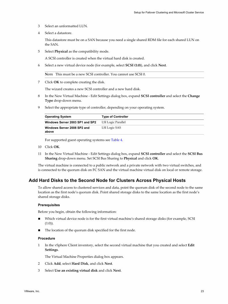
3 Select an unformatted LUN.
4 Select a datastore.
This datastore must be on a SAN because you need a single shared RDM file for each shared LUN onthe SAN.
5 Select Physical as the compatibility mode.
A SCSI controller is created when the virtual hard disk is created.
6 Select a new virtual device node (for example, select SCSI (1:0)), and click Next.
NOTE This must be a new SCSI controller. You cannot use SCSI 0.
7 Click OK to complete creating the disk.
The wizard creates a new SCSI controller and a new hard disk.
8 In the New Virtual Machine - Edit Settings dialog box, expand SCSI controller and select the ChangeType drop-down menu.
9 Select the appropriate type of controller, depending on your operating system.
Operating System Type of Controller
Windows Server 2003 SP1 and SP2 LSI Logic Parallel
Windows Server 2008 SP2 andabove
LSI Logic SAS
For supported guest operating systems see Table 4.
10 Click OK.
11 In the New Virtual Machine - Edit Settings dialog box, expand SCSI controller and select the SCSI BusSharing drop-down menu. Set SCSI Bus Sharing to Physical and click OK.
The virtual machine is connected to a public network and a private network with two virtual switches, andis connected to the quorum disk on FC SAN and the virtual machine virtual disk on local or remote storage.
Add Hard Disks to the Second Node for Clusters Across Physical HostsTo allow shared access to clustered services and data, point the quorum disk of the second node to the samelocation as the first node’s quorum disk. Point shared storage disks to the same location as the first node’sshared storage disks.
Prerequisites
Before you begin, obtain the following information:
n Which virtual device node is for the first virtual machine's shared storage disks (for example, SCSI(1:0)).
n The location of the quorum disk specified for the first node.
Procedure
1 In the vSphere Client inventory, select the second virtual machine that you created and select EditSettings.
The Virtual Machine Properties dialog box appears.
2 Click Add, select Hard Disk, and click Next.
3 Select Use an existing virtual disk and click Next.
Setup for Failover Clustering and Microsoft Cluster Service
VMware, Inc. 23
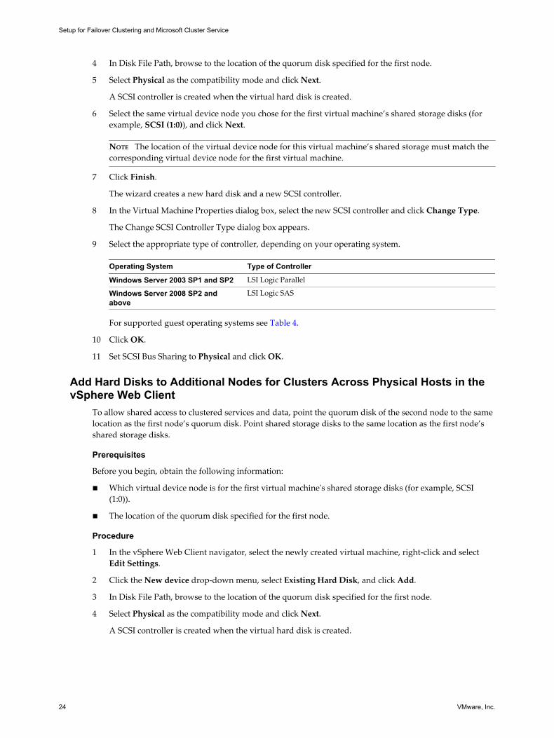
4 In Disk File Path, browse to the location of the quorum disk specified for the first node.
5 Select Physical as the compatibility mode and click Next.
A SCSI controller is created when the virtual hard disk is created.
6 Select the same virtual device node you chose for the first virtual machine’s shared storage disks (forexample, SCSI (1:0)), and click Next.
NOTE The location of the virtual device node for this virtual machine’s shared storage must match thecorresponding virtual device node for the first virtual machine.
7 Click Finish.
The wizard creates a new hard disk and a new SCSI controller.
8 In the Virtual Machine Properties dialog box, select the new SCSI controller and click Change Type.
The Change SCSI Controller Type dialog box appears.
9 Select the appropriate type of controller, depending on your operating system.
Operating System Type of Controller
Windows Server 2003 SP1 and SP2 LSI Logic Parallel
Windows Server 2008 SP2 andabove
LSI Logic SAS
For supported guest operating systems see Table 4.
10 Click OK.
11 Set SCSI Bus Sharing to Physical and click OK.
Add Hard Disks to Additional Nodes for Clusters Across Physical Hosts in thevSphere Web Client
To allow shared access to clustered services and data, point the quorum disk of the second node to the samelocation as the first node’s quorum disk. Point shared storage disks to the same location as the first node’sshared storage disks.
Prerequisites
Before you begin, obtain the following information:
n Which virtual device node is for the first virtual machine's shared storage disks (for example, SCSI(1:0)).
n The location of the quorum disk specified for the first node.
Procedure
1 In the vSphere Web Client navigator, select the newly created virtual machine, right-click and selectEdit Settings.
2 Click the New device drop-down menu, select Existing Hard Disk, and click Add.
3 In Disk File Path, browse to the location of the quorum disk specified for the first node.
4 Select Physical as the compatibility mode and click Next.
A SCSI controller is created when the virtual hard disk is created.
Setup for Failover Clustering and Microsoft Cluster Service
24 VMware, Inc.
5 Select the same virtual device node you chose for the first virtual machine’s shared storage disks (forexample, SCSI (1:0)), and click OK.
NOTE The location of the virtual device node for this virtual machine’s shared storage must match thecorresponding virtual device node for the first virtual machine.
6 Click OK.
The wizard creates a new hard disk and a new SCSI controller.
7 In the New Virtual Machine - Edit Settings dialog box, expand SCSI controller and select the ChangeType drop-down menu.
8 Select the appropriate type of controller, depending on your operating system.
Operating System Type of Controller
Windows Server 2003 SP1 and SP2 LSI Logic Parallel
Windows Server 2008 SP2 andabove
LSI Logic SAS
For supported guest operating systems see Table 4.
9 Click OK.
10 Set SCSI Bus Sharing to Physical and click OK.
Cluster Physical and Virtual MachinesYou can create an MSCS cluster in which each physical machine has a corresponding virtual machine. Thistype of configuration is known as a standby host cluster.
A standby host cluster has specific hardware and software requirements.
n Use ESXi hosts that have the following:
n Two physical network adapters dedicated to the MSCS cluster and to the public and privatenetworks.
n One physical network adapter dedicated to the VMkernel.
n Use RDMs in physical compatibility mode (pass-through RDM). You cannot use virtual disks or RDMsin virtual compatibility mode (non-pass-through RDM) for shared storage.
n Use the STORport Miniport driver for the Fibre Channel (FC) HBA (QLogic or Emulex) in the physicalWindows machine.
n Do not run multipathing software in the physical or virtual machines.
n Use only a single physical path from the host to the storage arrays in standby host configurations.
Create the First Node for a Cluster of Physical and Virtual MachinesThe first node in a standby host setup is a physical machine.
For information about setting up a physical machine that participates in an MSCS cluster, see the MicrosoftCluster Service documentation.
Setup for Failover Clustering and Microsoft Cluster Service
VMware, Inc. 25
Procedure
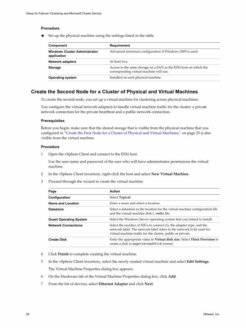
u Set up the physical machine using the settings listed in the table.
Component Requirement
Windows Cluster Administratorapplication
Advanced minimum configuration if Windows 2003 is used.
Network adapters At least two.
Storage Access to the same storage on a SAN as the ESXi host on which thecorresponding virtual machine will run.
Operating system Installed on each physical machine.
Create the Second Node for a Cluster of Physical and Virtual MachinesTo create the second node, you set up a virtual machine for clustering across physical machines.
You configure the virtual network adapters to handle virtual machine traffic for the cluster: a privatenetwork connection for the private heartbeat and a public network connection.
Prerequisites
Before you begin, make sure that the shared storage that is visible from the physical machine that youconfigured in “Create the First Node for a Cluster of Physical and Virtual Machines,” on page 25 is alsovisible from the virtual machine.
Procedure
1 Open the vSphere Client and connect to the ESXi host.
Use the user name and password of the user who will have administrator permissions the virtualmachine.
2 In the vSphere Client inventory, right-click the host and select New Virtual Machine.
3 Proceed through the wizard to create the virtual machine.
Page Action
Configuration Select Typical.
Name and Location Enter a name and select a location.
Datastore Select a datastore as the location for the virtual machine configuration fileand the virtual machine disk (.vmdk) file.
Guest Operating System Select the Windows Server operating system that you intend to install.
Network Connections Select the number of NICs to connect (1), the adapter type, and thenetwork label. The network label refers to the network to be used forvirtual machine traffic for the cluster, public or private.
Create Disk Enter the appropriate value in Virtual disk size. Select Thick Provision tocreate a disk in eagerzeroedthick format.
4 Click Finish to complete creating the virtual machine.
5 In the vSphere Client inventory, select the newly created virtual machine and select Edit Settings.
The Virtual Machine Properties dialog box appears.
6 On the Hardware tab of the Virtual Machine Properties dialog box, click Add.
7 From the list of devices, select Ethernet Adapter and click Next.
Setup for Failover Clustering and Microsoft Cluster Service
26 VMware, Inc.
8 Select the adapter type and network label.
n If you selected a private network for the first network adapter, you must select a public networkfor this network adapter.
n If you selected a public network for the first network adapter, you must select a private networkadapter.
9 Click Next, and click Finish to complete creating the device.
10 Install a Windows Server operating system on the virtual machine.
Create the Second Node for a Cluster of Physical and Virtual Machines in thevSphere Web Client
To create the second node, you set up a virtual machine for clustering across physical machines.
You configure the virtual network adapters to handle virtual machine traffic for the cluster: a privatenetwork connection for the private heartbeat and a public network connection.
Prerequisites
Before you begin, make sure that the shared storage that is visible from the physical machine that youconfigured in “Create the First Node for a Cluster of Physical and Virtual Machines,” on page 25 is alsovisible from the virtual machine.
Procedure
1 Open the vSphere Web Client and connect to the vCenter Server system.
Use the user name and password of the user who will have administrator permissions on the virtualmachine.
2 In the vSphere Web Client navigator, right-click the host and select New Virtual Machine.
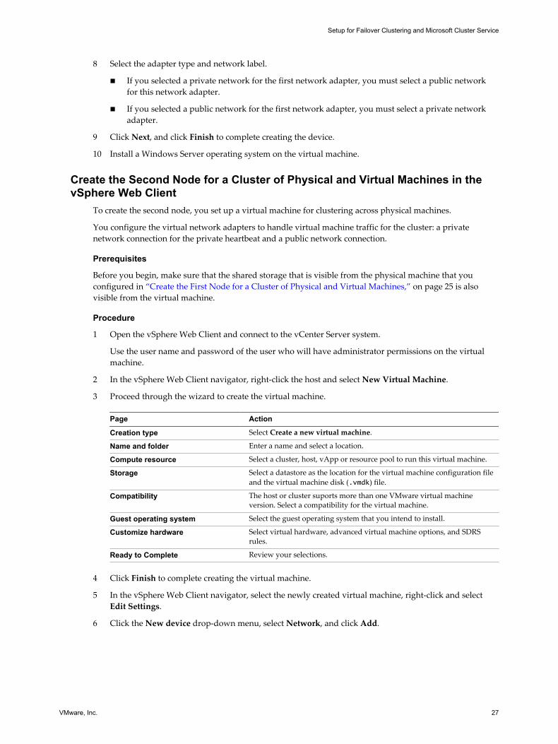
3 Proceed through the wizard to create the virtual machine.
Page Action
Creation type Select Create a new virtual machine.
Name and folder Enter a name and select a location.
Compute resource Select a cluster, host, vApp or resource pool to run this virtual machine.
Storage Select a datastore as the location for the virtual machine configuration fileand the virtual machine disk (.vmdk) file.
Compatibility The host or cluster suports more than one VMware virtual machineversion. Select a compatibility for the virtual machine.
Guest operating system Select the guest operating system that you intend to install.
Customize hardware Select virtual hardware, advanced virtual machine options, and SDRSrules.
Ready to Complete Review your selections.
4 Click Finish to complete creating the virtual machine.
5 In the vSphere Web Client navigator, select the newly created virtual machine, right-click and selectEdit Settings.
6 Click the New device drop-down menu, select Network, and click Add.
Setup for Failover Clustering and Microsoft Cluster Service
VMware, Inc. 27
7 In the New Virtual Machine - Edit Settings dialog box, expand Network adapter. Select the adaptertype and network label.
n If you selected a private network for the first network adapter, you must select a public networkfor this network adapter.
n If you selected a public network for the first network adapter, you must select a private networkadapter.
8 Click Finish to complete creating the device.
9 Install a Windows Server operating system on the virtual machine.
Add Hard Disks to the Second Node for a Cluster of Physical and VirtualMachines
When you add hard disks to the second node, you set up the disks to point to the quorum disk and sharedstorage disks, if any, for the first node. The setup allows shared access to clustered services and data.
Procedure
1 In the vSphere Client inventory, select the newly created virtual machine and select Edit Settings.
The Virtual Machine Properties dialog box appears.
2 Click Add, select Hard Disk, and click Next.
3 Select Raw Device Mappings and click Next.
4 Select the LUN that is used by the physical machine.
5 Select the datastore, which is also the location of the boot disk, and click Next.
6 Select Physical as the compatibility mode and click Next.
A SCSI controller is created when the virtual hard disk is created.
7 From the Virtual Device Node drop-down menu, select a new SCSI controller (for example, SCSI (1:0)).
NOTE You must select a new virtual device node. You cannot use SCSI 0.
8 Click Next, and click Finish.
The wizard creates a new hard disk and a new SCSI controller.
9 In the Virtual Machine Properties dialog box, select the new SCSI controller and click Change Type.
The Change SCSI Controller Type dialog box appears.
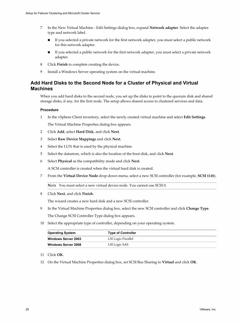
10 Select the appropriate type of controller, depending on your operating system.
Operating System Type of Controller
Windows Server 2003 LSI Logic Parallel
Windows Server 2008 LSI Logic SAS
11 Click OK.
12 On the Virtual Machine Properties dialog box, set SCSI Bus Sharing to Virtual and click OK.
Setup for Failover Clustering and Microsoft Cluster Service
28 VMware, Inc.
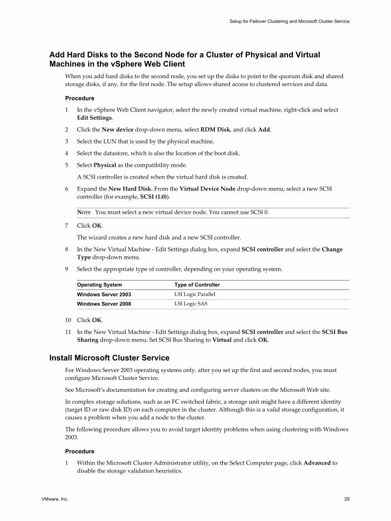
Add Hard Disks to the Second Node for a Cluster of Physical and VirtualMachines in the vSphere Web Client
When you add hard disks to the second node, you set up the disks to point to the quorum disk and sharedstorage disks, if any, for the first node. The setup allows shared access to clustered services and data.
Procedure
1 In the vSphere Web Client navigator, select the newly created virtual machine, right-click and selectEdit Settings.
2 Click the New device drop-down menu, select RDM Disk, and click Add.
3 Select the LUN that is used by the physical machine.
4 Select the datastore, which is also the location of the boot disk.
5 Select Physical as the compatibility mode.
A SCSI controller is created when the virtual hard disk is created.
6 Expand the New Hard Disk. From the Virtual Device Node drop-down menu, select a new SCSIcontroller (for example, SCSI (1:0)).
NOTE You must select a new virtual device node. You cannot use SCSI 0.
7 Click OK.
The wizard creates a new hard disk and a new SCSI controller.
8 In the New Virtual Machine - Edit Settings dialog box, expand SCSI controller and select the ChangeType drop-down menu.
9 Select the appropriate type of controller, depending on your operating system.
Operating System Type of Controller
Windows Server 2003 LSI Logic Parallel
Windows Server 2008 LSI Logic SAS
10 Click OK.
11 In the New Virtual Machine - Edit Settings dialog box, expand SCSI controller and select the SCSI BusSharing drop-down menu. Set SCSI Bus Sharing to Virtual and click OK.
Install Microsoft Cluster ServiceFor Windows Server 2003 operating systems only, after you set up the first and second nodes, you mustconfigure Microsoft Cluster Service.
See Microsoft’s documentation for creating and configuring server clusters on the Microsoft Web site.
In complex storage solutions, such as an FC switched fabric, a storage unit might have a different identity(target ID or raw disk ID) on each computer in the cluster. Although this is a valid storage configuration, itcauses a problem when you add a node to the cluster.
The following procedure allows you to avoid target identity problems when using clustering with Windows2003.
Procedure
1 Within the Microsoft Cluster Administrator utility, on the Select Computer page, click Advanced todisable the storage validation heuristics.
Setup for Failover Clustering and Microsoft Cluster Service
VMware, Inc. 29
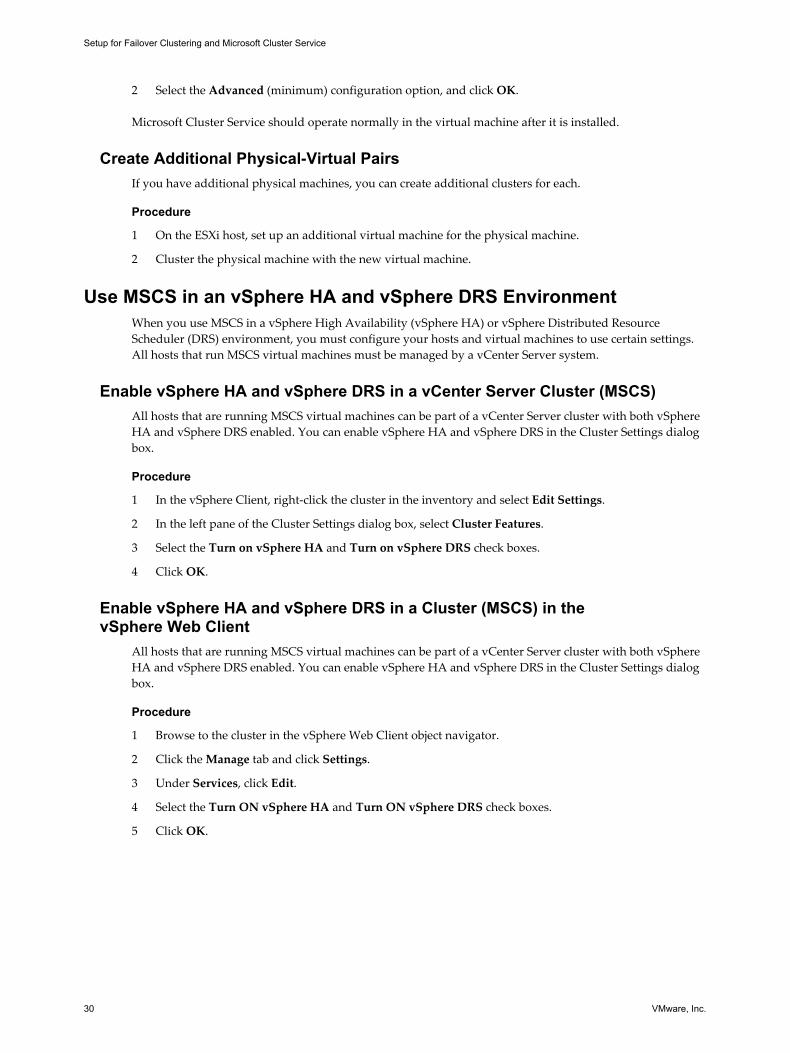
2 Select the Advanced (minimum) configuration option, and click OK.
Microsoft Cluster Service should operate normally in the virtual machine after it is installed.
Create Additional Physical-Virtual PairsIf you have additional physical machines, you can create additional clusters for each.
Procedure
1 On the ESXi host, set up an additional virtual machine for the physical machine.
2 Cluster the physical machine with the new virtual machine.
Use MSCS in an vSphere HA and vSphere DRS EnvironmentWhen you use MSCS in a vSphere High Availability (vSphere HA) or vSphere Distributed ResourceScheduler (DRS) environment, you must configure your hosts and virtual machines to use certain settings.All hosts that run MSCS virtual machines must be managed by a vCenter Server system.
Enable vSphere HA and vSphere DRS in a vCenter Server Cluster (MSCS)All hosts that are running MSCS virtual machines can be part of a vCenter Server cluster with both vSphereHA and vSphere DRS enabled. You can enable vSphere HA and vSphere DRS in the Cluster Settings dialogbox.
Procedure
1 In the vSphere Client, right-click the cluster in the inventory and select Edit Settings.
2 In the left pane of the Cluster Settings dialog box, select Cluster Features.
3 Select the Turn on vSphere HA and Turn on vSphere DRS check boxes.
4 Click OK.
Enable vSphere HA and vSphere DRS in a Cluster (MSCS) in thevSphere Web Client
All hosts that are running MSCS virtual machines can be part of a vCenter Server cluster with both vSphereHA and vSphere DRS enabled. You can enable vSphere HA and vSphere DRS in the Cluster Settings dialogbox.
Procedure
1 Browse to the cluster in the vSphere Web Client object navigator.
2 Click the Manage tab and click Settings.
3 Under Services, click Edit.
4 Select the Turn ON vSphere HA and Turn ON vSphere DRS check boxes.
5 Click OK.
Setup for Failover Clustering and Microsoft Cluster Service
30 VMware, Inc.
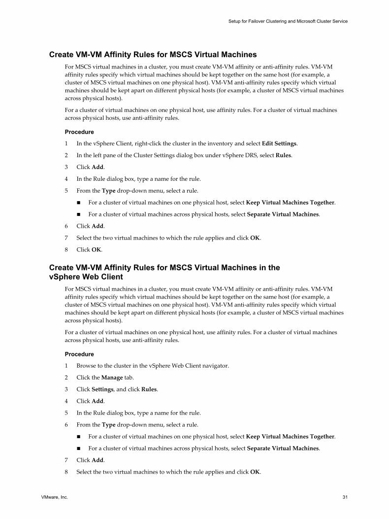
Create VM-VM Affinity Rules for MSCS Virtual MachinesFor MSCS virtual machines in a cluster, you must create VM-VM affinity or anti-affinity rules. VM-VMaffinity rules specify which virtual machines should be kept together on the same host (for example, acluster of MSCS virtual machines on one physical host). VM-VM anti-affinity rules specify which virtualmachines should be kept apart on different physical hosts (for example, a cluster of MSCS virtual machinesacross physical hosts).
For a cluster of virtual machines on one physical host, use affinity rules. For a cluster of virtual machinesacross physical hosts, use anti-affinity rules.
Procedure
1 In the vSphere Client, right-click the cluster in the inventory and select Edit Settings.
2 In the left pane of the Cluster Settings dialog box under vSphere DRS, select Rules.
3 Click Add.
4 In the Rule dialog box, type a name for the rule.
5 From the Type drop-down menu, select a rule.
n For a cluster of virtual machines on one physical host, select Keep Virtual Machines Together.
n For a cluster of virtual machines across physical hosts, select Separate Virtual Machines.
6 Click Add.
7 Select the two virtual machines to which the rule applies and click OK.
8 Click OK.
Create VM-VM Affinity Rules for MSCS Virtual Machines in thevSphere Web Client
For MSCS virtual machines in a cluster, you must create VM-VM affinity or anti-affinity rules. VM-VMaffinity rules specify which virtual machines should be kept together on the same host (for example, acluster of MSCS virtual machines on one physical host). VM-VM anti-affinity rules specify which virtualmachines should be kept apart on different physical hosts (for example, a cluster of MSCS virtual machinesacross physical hosts).
For a cluster of virtual machines on one physical host, use affinity rules. For a cluster of virtual machinesacross physical hosts, use anti-affinity rules.
Procedure
1 Browse to the cluster in the vSphere Web Client navigator.
2 Click the Manage tab.
3 Click Settings, and click Rules.
4 Click Add.
5 In the Rule dialog box, type a name for the rule.
6 From the Type drop-down menu, select a rule.
n For a cluster of virtual machines on one physical host, select Keep Virtual Machines Together.
n For a cluster of virtual machines across physical hosts, select Separate Virtual Machines.
7 Click Add.
8 Select the two virtual machines to which the rule applies and click OK.
Setup for Failover Clustering and Microsoft Cluster Service
VMware, Inc. 31
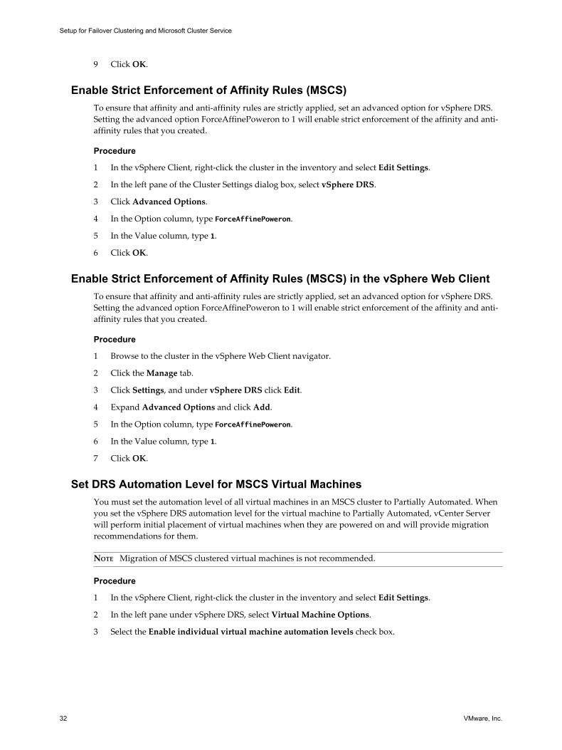
9 Click OK.
Enable Strict Enforcement of Affinity Rules (MSCS)To ensure that affinity and anti-affinity rules are strictly applied, set an advanced option for vSphere DRS.Setting the advanced option ForceAffinePoweron to 1 will enable strict enforcement of the affinity and anti-affinity rules that you created.
Procedure
1 In the vSphere Client, right-click the cluster in the inventory and select Edit Settings.
2 In the left pane of the Cluster Settings dialog box, select vSphere DRS.
3 Click Advanced Options.
4 In the Option column, type ForceAffinePoweron.
5 In the Value column, type 1.
6 Click OK.
Enable Strict Enforcement of Affinity Rules (MSCS) in the vSphere Web ClientTo ensure that affinity and anti-affinity rules are strictly applied, set an advanced option for vSphere DRS.Setting the advanced option ForceAffinePoweron to 1 will enable strict enforcement of the affinity and anti-affinity rules that you created.
Procedure
1 Browse to the cluster in the vSphere Web Client navigator.
2 Click the Manage tab.
3 Click Settings, and under vSphere DRS click Edit.
4 Expand Advanced Options and click Add.
5 In the Option column, type ForceAffinePoweron.
6 In the Value column, type 1.
7 Click OK.
Set DRS Automation Level for MSCS Virtual MachinesYou must set the automation level of all virtual machines in an MSCS cluster to Partially Automated. Whenyou set the vSphere DRS automation level for the virtual machine to Partially Automated, vCenter Serverwill perform initial placement of virtual machines when they are powered on and will provide migrationrecommendations for them.
NOTE Migration of MSCS clustered virtual machines is not recommended.
Procedure
1 In the vSphere Client, right-click the cluster in the inventory and select Edit Settings.
2 In the left pane under vSphere DRS, select Virtual Machine Options.
3 Select the Enable individual virtual machine automation levels check box.
Setup for Failover Clustering and Microsoft Cluster Service
32 VMware, Inc.
4 Change the virtual machine automation level for each MSCS virtual machine in the cluster.
a In the Virtual Machine column, select the virtual machine.
b In the Automation Level column, select Partially Automated from the drop-down menu.
c Repeat Step 4a and Step 4b for each virtual machine.
5 Click OK.
Set DRS Automation Level for MSCS Virtual Machines in thevSphere Web Client
You must set the automation level of all virtual machines in an MSCS cluster to Partially Automated. Whenyou set the vSphere DRS automation level for the virtual machine to Partially Automated, vCenter Serverwill perform initial placement of virtual machines when they are powered on and will provide migrationrecommendations for them.
NOTE Migration of MSCS clustered virtual machines is not recommended.
Procedure
1 Browse to the cluster in the vSphere Web Client object navigator.
2 Click the Manage tab and click Settings.
3 Under Services, click Edit.
4 Expand DRS Automation, under Virtual Machine Automation select the Enable individual virtualmachine automation levels check box and click OK.
5 Under Configuration, select VM Overrides and click Add.
6 Click the + button, select the MSCS virtual machines in the cluster and click OK.
7 Click the Automation level drop-down menu, and select Partially Automated.
8 Click OK.
Using vSphere DRS Groups and VM-Host Affinity Rules with MSCS VirtualMachines
You can use the vSphere Client to set up two types of DRS groups: virtual machine DRS groups, whichcontain at least one virtual machine, and host DRS groups, which contain at least one host. A VM-Hostaffinity rule establishes an affinity (or anti-affinity) relationship between a virtual machine DRS group and ahost DRS group.
You must use VM-Host affinity rules because vSphere HA does not obey VM-VM affinity rules. This meansthat if a host fails, vSphere HA might separate clustered virtual machines that are meant to stay together, orvSphere HA might put clustered virtual machines that are meant to stay apart on the same host. You canavoid this problem by setting up DRS groups and using VM-Host affinity rules, which are obeyed byvSphere HA.
For a cluster of virtual machines on one physical host, all MSCS virtual machines must be in the samevirtual machine DRS group, linked to the same host DRS group with the affinity rule "Must run on hosts ingroup."
Setup for Failover Clustering and Microsoft Cluster Service
VMware, Inc. 33
For a cluster of virtual machines across physical hosts, each MSCS virtual machine must be in a differentvirtual machine DRS group, linked to a different host DRS group with the affinity rule "Must run on hosts ingroup."
CAUTION Limit the number of hosts to two when you define host DRS group rules for a cluster of virtualmachines on one physical host. (This does not apply to clusters of virtual machines across physical hosts.)Since vSphere HA does not obey VM-VM affinity rules, virtual machines in the configuration could bespread across hosts during a vSphere HA recovery from host failure if more than two hosts are included in ahost DRS group rule.
Create a Virtual Machine DRS Group (MSCS)Before you can create a VM-Host affinity rule, you must create the host DRS group and the virtual machineDRS group that the rule applies to.
For a cluster of virtual machines on one physical host, create one virtual machine DRS group that containsall MSCS virtual machines. For example, VMGroup_1 contains MSCS_VM_1 and MSCS_VM_2.
For a cluster of virtual machines across physical hosts, create one virtual machines DRS group for eachMSCS virtual machine. For example, VMGroup_1 contains MSCS_VM_1 and VMGroup_2 containsMSCS_VM_2.
Procedure
1 In the vSphere Client, right-click the cluster in the inventory and select Edit Settings.
2 In the left pane of the cluster Settings dialog box under vSphere DRS, select DRS Groups Manager.
3 In the Virtual Machines DRS Groups section, click Add.
4 In the DRS Group dialog box, type a name for the group (for example, VMGroup_1).
5 In the left pane, select the virtual machine and click >> to add it to the group.
n For a cluster of virtual machines on one physical host, add all MSCS virtual machines to one group.
n For a cluster of virtual machines across physical hosts, add one MSCS virtual machine per group.
6 Click OK.
Create a Virtual Machine DRS Group (MSCS) in the vSphere Web ClientBefore you can create a VM-Host affinity rule, you must create the host DRS group and the virtual machineDRS group that the rule applies to.
For a cluster of virtual machines on one physical host, create one virtual machine DRS group that containsall MSCS virtual machines. For example, VMGroup_1 contains MSCS_VM_1 and MSCS_VM_2.
For a cluster of virtual machines across physical hosts, create one virtual machines DRS group for eachMSCS virtual machine. For example, VMGroup_1 contains MSCS_VM_1 and VMGroup_2 containsMSCS_VM_2.
Procedure
1 Browse to the cluster in the vSphere Web Client navigator.
2 Click the Manage tab.
3 Click Settings, click DRS Groups and click Add.
4 In the DRS Group dialog box, type a name for the group.
5 Select VM DRS Group from the Type drop down box and click Add.
Setup for Failover Clustering and Microsoft Cluster Service
34 VMware, Inc.
6 Click the check box next to a virtual machine to add it. Continue this process until all desired virtualmachines have been added.
n For a cluster of virtual machines on one physical host, add all MSCS virtual machines to one group.
n For a cluster of virtual machines across physical hosts, add one MSCS virtual machine per group.
7 Click OK.
Create a Host DRS Group (MSCS)Before you can create a VM-Host affinity rule, you must create the host DRS group and the virtual machineDRS group that the rule applies to.
For a cluster of virtual machines on one physical host, create one host DRS group that contains the ESXihosts. For example, HostGroup_1 contains ESXi_HOST_1 and ESXi_HOST_2.
For a cluster of virtual machines across physical hosts, create groups with sets of hosts that do not overlap.This ensures that virtual machines placed in different host groups do not ever run on the same hostsimultaneously.
Procedure
1 In the vSphere Client, right-click the cluster in the inventory and select Edit Settings.
2 In the left pane of the cluster Settings dialog box under vSphere DRS, select DRS Groups Manager.
3 In the Host DRS Groups section, click Add.
4 In the DRS Group dialog box, type a name for the group (for example, HostGroup_1).
5 In the left pane, select a host and click >> to add it to the group.
6 Click OK.
Create a Host DRS Group (MSCS) in the vSphere Web ClientBefore you can create a VM-Host affinity rule, you must create the host DRS group and the virtual machineDRS group that the rule applies to.
For a cluster of virtual machines on one physical host, create one host DRS group that contains the ESXihosts. For example, HostGroup_1 contains ESXi_HOST_1 and ESXi_HOST_2.
For a cluster of virtual machines across physical hosts, create groups with sets of hosts that do not overlap.This ensures that virtual machines placed in different host groups do not ever run on the same hostsimultaneously.
Procedure
1 Browse to the cluster in the vSphere Web Client navigator.
2 Click the Manage tab.
3 Click Settings, click DRS Groups and click Add.
4 In the DRS Group dialog box, type a name for the group (for example, HostGroup_1).
5 Select Host DRS Group from the Type drop down box and click Add.
6 Click the check box next to a host to add it. Continue this process until all desired hosts have beenadded.
7 Click OK.
Setup for Failover Clustering and Microsoft Cluster Service
VMware, Inc. 35
Set up VM-Host Affinity Rules for DRS Groups (MSCS)Create VM-Host affinity rules to specify whether the members of a selected virtual machine DRS group canrun on the members of a specific host DRS group.
Prerequisites
Create virtual machine DRS groups that contain one or more MSCS virtual machines as described in “Createa Virtual Machine DRS Group (MSCS),” on page 34.
Create host DRS groups that contain one or more ESXi hosts, as described in “Create a Host DRS Group(MSCS),” on page 35.
Procedure
1 In the vSphere Client, right-click the cluster in the inventory and select Edit Settings.
2 In the left pane of the Cluster Settings dialog box under vSphere DRS, select Rules.
3 Click Add.
4 In the Rule dialog box, type a name for the rule.
5 From the Type menu, select Virtual Machines to Hosts.
6 Select the virtual machine DRS group and the host DRS group to which the rule applies.
For example, select VMGroup_1 and HostGroup_1.
7 Select Must run on hosts in group.
8 Click OK.
Set up VM-Host Affinity Rules for DRS Groups (MSCS) in the vSphere Web ClientCreate VM-Host affinity rules to specify whether the members of a selected virtual machine DRS group canrun on the members of a specific host DRS group.
Prerequisites
Create virtual machine DRS groups that contain one or more MSCS virtual machines as described in “Createa Virtual Machine DRS Group (MSCS),” on page 34.
Create host DRS groups that contain one or more ESXi hosts, as described in “Create a Host DRS Group(MSCS),” on page 35.
Procedure
1 Browse to the cluster in the vSphere Web Client navigator.
2 Click the Manage tab.
3 Click Settings, click DRS Rules and click Add.
4 In the DRS Rule dialog box, type a name for the rule.
5 From the Type menu, select Virtual Machines to Hosts.
6 Select the virtual machine DRS group and the host DRS group to which the rule applies.
For example, select VMGroup_1 and HostGroup_1.
7 Select Must run on hosts in group.
8 Click OK.
Setup for Failover Clustering and Microsoft Cluster Service
36 VMware, Inc.
vSphere MSCS Setup ChecklistWhen you set up MSCS on ESXi, see the checklists to configure your environment according to therequirements. You can also use the checklists to verify that your setup meets the requirements if you needtechnical support.
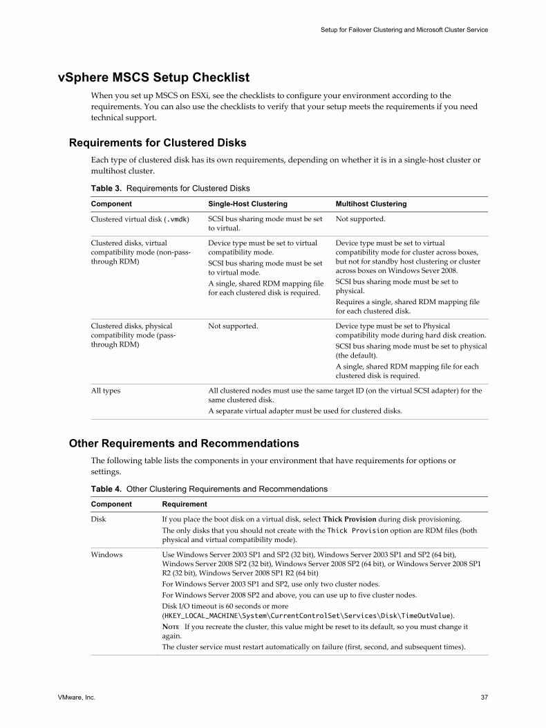
Requirements for Clustered DisksEach type of clustered disk has its own requirements, depending on whether it is in a single-host cluster ormultihost cluster.
Table 3. Requirements for Clustered Disks
Component Single-Host Clustering Multihost Clustering
Clustered virtual disk (.vmdk) SCSI bus sharing mode must be setto virtual.
Not supported.
Clustered disks, virtualcompatibility mode (non-pass-through RDM)
Device type must be set to virtualcompatibility mode.SCSI bus sharing mode must be setto virtual mode.A single, shared RDM mapping filefor each clustered disk is required.
Device type must be set to virtualcompatibility mode for cluster across boxes,but not for standby host clustering or clusteracross boxes on Windows Sever 2008.SCSI bus sharing mode must be set tophysical.Requires a single, shared RDM mapping filefor each clustered disk.
Clustered disks, physicalcompatibility mode (pass-through RDM)
Not supported. Device type must be set to Physicalcompatibility mode during hard disk creation.SCSI bus sharing mode must be set to physical(the default).A single, shared RDM mapping file for eachclustered disk is required.
All types All clustered nodes must use the same target ID (on the virtual SCSI adapter) for thesame clustered disk.A separate virtual adapter must be used for clustered disks.
Other Requirements and RecommendationsThe following table lists the components in your environment that have requirements for options orsettings.
Table 4. Other Clustering Requirements and Recommendations
Component Requirement
Disk If you place the boot disk on a virtual disk, select Thick Provision during disk provisioning.The only disks that you should not create with the Thick Provision option are RDM files (bothphysical and virtual compatibility mode).
Windows Use Windows Server 2003 SP1 and SP2 (32 bit), Windows Server 2003 SP1 and SP2 (64 bit),Windows Server 2008 SP2 (32 bit), Windows Server 2008 SP2 (64 bit), or Windows Server 2008 SP1R2 (32 bit), Windows Server 2008 SP1 R2 (64 bit)For Windows Server 2003 SP1 and SP2, use only two cluster nodes.For Windows Server 2008 SP2 and above, you can use up to five cluster nodes.Disk I/O timeout is 60 seconds or more(HKEY_LOCAL_MACHINE\System\CurrentControlSet\Services\Disk\TimeOutValue).NOTE If you recreate the cluster, this value might be reset to its default, so you must change itagain.The cluster service must restart automatically on failure (first, second, and subsequent times).
Setup for Failover Clustering and Microsoft Cluster Service
VMware, Inc. 37
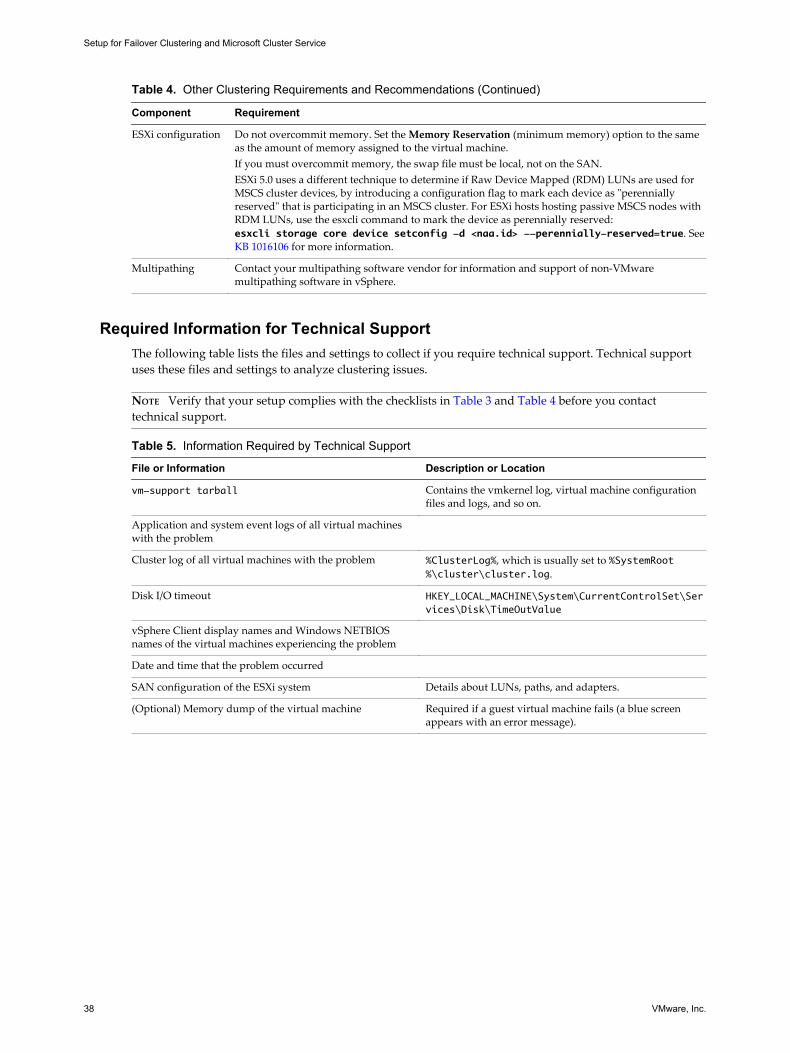
Table 4. Other Clustering Requirements and Recommendations (Continued)
Component Requirement
ESXi configuration Do not overcommit memory. Set the Memory Reservation (minimum memory) option to the sameas the amount of memory assigned to the virtual machine.If you must overcommit memory, the swap file must be local, not on the SAN.ESXi 5.0 uses a different technique to determine if Raw Device Mapped (RDM) LUNs are used forMSCS cluster devices, by introducing a configuration flag to mark each device as "perenniallyreserved" that is participating in an MSCS cluster. For ESXi hosts hosting passive MSCS nodes withRDM LUNs, use the esxcli command to mark the device as perennially reserved:esxcli storage core device setconfig -d <naa.id> --perennially-reserved=true. See KB 1016106 for more information.
Multipathing Contact your multipathing software vendor for information and support of non-VMwaremultipathing software in vSphere.
Required Information for Technical SupportThe following table lists the files and settings to collect if you require technical support. Technical supportuses these files and settings to analyze clustering issues.
NOTE Verify that your setup complies with the checklists in Table 3 and Table 4 before you contacttechnical support.
Table 5. Information Required by Technical Support
File or Information Description or Location
vm-support tarball Contains the vmkernel log, virtual machine configurationfiles and logs, and so on.
Application and system event logs of all virtual machineswith the problem
Cluster log of all virtual machines with the problem %ClusterLog%, which is usually set to %SystemRoot%\cluster\cluster.log.
Disk I/O timeout HKEY_LOCAL_MACHINE\System\CurrentControlSet\Services\Disk\TimeOutValue
vSphere Client display names and Windows NETBIOSnames of the virtual machines experiencing the problem
Date and time that the problem occurred
SAN configuration of the ESXi system Details about LUNs, paths, and adapters.
(Optional) Memory dump of the virtual machine Required if a guest virtual machine fails (a blue screenappears with an error message).
Setup for Failover Clustering and Microsoft Cluster Service
38 VMware, Inc.
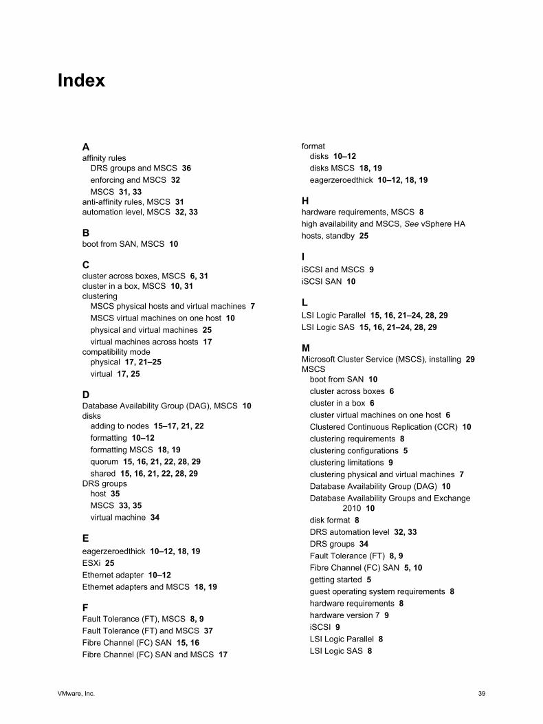
Index
Aaffinity rules
DRS groups and MSCS 36enforcing and MSCS 32MSCS 31, 33
anti-affinity rules, MSCS 31automation level, MSCS 32, 33
Bboot from SAN, MSCS 10
Ccluster across boxes, MSCS 6, 31cluster in a box, MSCS 10, 31clustering
MSCS physical hosts and virtual machines 7MSCS virtual machines on one host 10physical and virtual machines 25virtual machines across hosts 17
compatibility modephysical 17, 21–25virtual 17, 25
DDatabase Availability Group (DAG), MSCS 10disks
adding to nodes 15–17, 21, 22formatting 10–12formatting MSCS 18, 19quorum 15, 16, 21, 22, 28, 29shared 15, 16, 21, 22, 28, 29
DRS groupshost 35MSCS 33, 35virtual machine 34
Eeagerzeroedthick 10–12, 18, 19ESXi 25Ethernet adapter 10–12Ethernet adapters and MSCS 18, 19
FFault Tolerance (FT), MSCS 8, 9Fault Tolerance (FT) and MSCS 37Fibre Channel (FC) SAN 15, 16Fibre Channel (FC) SAN and MSCS 17
formatdisks 10–12disks MSCS 18, 19eagerzeroedthick 10–12, 18, 19
Hhardware requirements, MSCS 8high availability and MSCS, See vSphere HAhosts, standby 25
IiSCSI and MSCS 9iSCSI SAN 10
LLSI Logic Parallel 15, 16, 21–24, 28, 29LSI Logic SAS 15, 16, 21–24, 28, 29
MMicrosoft Cluster Service (MSCS), installing 29MSCS
boot from SAN 10cluster across boxes 6cluster in a box 6cluster virtual machines on one host 6Clustered Continuous Replication (CCR) 10clustering requirements 8clustering configurations 5clustering limitations 9clustering physical and virtual machines 7Database Availability Group (DAG) 10Database Availability Groups and Exchange
2010 10disk format 8DRS automation level 32, 33DRS groups 34Fault Tolerance (FT) 8, 9Fibre Channel (FC) SAN 5, 10getting started 5guest operating system requirements 8hardware requirements 8hardware version 7 9iSCSI 9LSI Logic Parallel 8LSI Logic SAS 8
VMware, Inc. 39
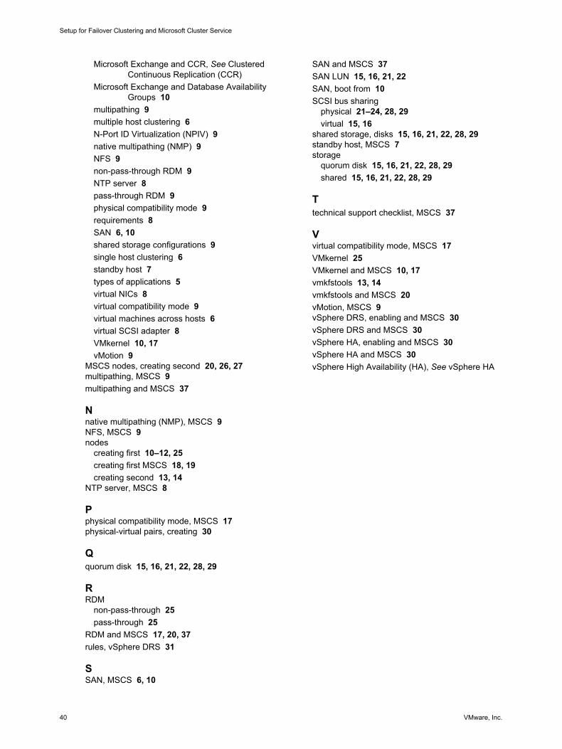
Microsoft Exchange and CCR, See ClusteredContinuous Replication (CCR)
Microsoft Exchange and Database AvailabilityGroups 10
multipathing 9multiple host clustering 6N-Port ID Virtualization (NPIV) 9native multipathing (NMP) 9NFS 9non-pass-through RDM 9NTP server 8pass-through RDM 9physical compatibility mode 9requirements 8SAN 6, 10shared storage configurations 9single host clustering 6standby host 7types of applications 5virtual NICs 8virtual compatibility mode 9virtual machines across hosts 6virtual SCSI adapter 8VMkernel 10, 17vMotion 9
MSCS nodes, creating second 20, 26, 27multipathing, MSCS 9multipathing and MSCS 37
Nnative multipathing (NMP), MSCS 9NFS, MSCS 9nodes
creating first 10–12, 25creating first MSCS 18, 19creating second 13, 14
NTP server, MSCS 8
Pphysical compatibility mode, MSCS 17physical-virtual pairs, creating 30
Qquorum disk 15, 16, 21, 22, 28, 29
RRDM
non-pass-through 25pass-through 25
RDM and MSCS 17, 20, 37rules, vSphere DRS 31
SSAN, MSCS 6, 10
SAN and MSCS 37SAN LUN 15, 16, 21, 22SAN, boot from 10SCSI bus sharing
physical 21–24, 28, 29virtual 15, 16
shared storage, disks 15, 16, 21, 22, 28, 29standby host, MSCS 7storage
quorum disk 15, 16, 21, 22, 28, 29shared 15, 16, 21, 22, 28, 29
Ttechnical support checklist, MSCS 37
Vvirtual compatibility mode, MSCS 17VMkernel 25VMkernel and MSCS 10, 17vmkfstools 13, 14vmkfstools and MSCS 20vMotion, MSCS 9vSphere DRS, enabling and MSCS 30vSphere DRS and MSCS 30vSphere HA, enabling and MSCS 30vSphere HA and MSCS 30vSphere High Availability (HA), See vSphere HA
Setup for Failover Clustering and Microsoft Cluster Service
40 VMware, Inc.


![[MS-CSVP]: Failover Cluster: Setup and Validation … · Failover Cluster: Setup and Validation Protocol ... Failover Cluster: Setup and Validation Protocol (ClusPrep) ... cluster](https://img.dokumen.tips/doc/110x75/5add98057f8b9ae1408d3169/ms-csvp-failover-cluster-setup-and-validation-cluster-setup-and-validation.jpg)