Embed Size (px)
Citation preview
1
Session 4
Risk and Reliability
Design of Retaining Structures
Slopes, Overall Stability and
Embankments
(Blarney Castle)
2
Session 4a
Risk and reliability
3
Complexity and Geotechnical Risk
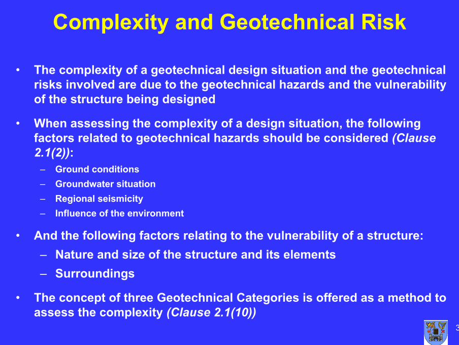
• The complexity of a geotechnical design situation and the geotechnical risks involved are due to the geotechnical hazards and the vulnerability of the structure being designed
• When assessing the complexity of a design situation, the following factors related to geotechnical hazards should be considered (Clause 2.1(2)):
– Ground conditions– Groundwater situation– Regional seismicity– Influence of the environment
• And the following factors relating to the vulnerability of a structure:– Nature and size of the structure and its elements– Surroundings
• The concept of three Geotechnical Categories is offered as a method to assess the complexity (Clause 2.1(10))
4
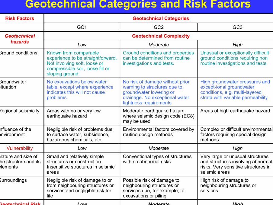
Geotechnical Categories and Risk Factors
HighModerateLowGeotechnical Risk
High risk of damage to neighbouring structures or services
Possible risk of damage to neighbouring structures or services due, for example, to excavations or piling
Negligible risk of damage to or from neighbouring structures or services and negligible risk for life
Surroundings
Very large or unusual structures and structures involving abnormal risks. Very sensitive structures in seismic areas
Conventional types of structures with no abnormal risks
Small and relatively simple structures or construction. Insensitive structures in seismic areas
Nature and size of the structure and its elements
HighModerateLowVulnerability
Complex or difficult environmental factors requiring special design methods
Environmental factors covered by routine design methods
Negligible risk of problems due to surface water, subsidence, hazardous chemicals, etc.
Influence of the environment
Areas of high earthquake hazardModerate earthquake hazard where seismic design code (EC8) may be used
Areas with no or very low earthquake hazard
Regional seismicity
High groundwater pressures and except-ional groundwater conditions, e.g. multi-layered strata with variable permeability
No risk of damage without prior warning to structures due to groundwater lowering or drainage. No exceptional water tightness requirements
No excavations below water table, except where experience indicates this will not cause problems
Groundwater situation
Unusual or exceptionally difficult ground conditions requiring non routine investigations and tests
Ground conditions and properties can be determined from routine investigations and tests.
Known from comparable experience to be straightforward. Not involving soft, loose or compressible soil, loose fill or sloping ground.
Ground conditions
HighModerateLow
Geotechnical ComplexityGeotechnicalhazards
GC3GC2GC1
Geotechnical CategoriesRisk Factors
5
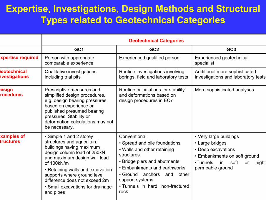
Expertise, Investigations, Design Methods and Structural Types related to Geotechnical Categories
• Very large buildings• Large bridges• Deep excavations• Embankments on soft ground•Tunnels in soft or highly permeable ground
Conventional:• Spread and pile foundations• Walls and other retaining structures• Bridge piers and abutments• Embankments and earthworks• Ground anchors and other support systems• Tunnels in hard, non-fractured rock
• Simple 1 and 2 storey structures and agricultural buildings having maximum design column load of 250kN and maximum design wall load of 100kN/m• Retaining walls and excavation supports where ground level difference does not exceed 2m• Small excavations for drainage and pipes
Examples of structures
More sophisticated analysesRoutine calculations for stability and deformations based on design procedures in EC7
Prescriptive measures and simplified design procedures, e.g. design bearing pressures based on experience or published presumed bearing pressures. Stability or deformation calculations may not be necessary.
Design procedures
Additional more sophisticated investigations and laboratory tests
Routine investigations involving borings, field and laboratory tests
Qualitative investigations including trial pits
Geotechnical investigations
Experienced geotechnical specialist
Experienced qualified personPerson with appropriate comparable experience
Expertise requiredGC3GC2GC1
Geotechnical Categories
6
Reliability
• All Eurocodes based on reliability analyses – i.e. aim to achieve structures with a certain target probability of failure:– 1x10⁻⁶ in 1 year for a ULS– 2x10⁻³ for an SLS– β = 3.8
• Target reliability achieved through:– Use of characteristic loads– Selection of characteristic parameter values– Choice of appropriate partial factor values
• Hence appropriate selection of characteristic values is essential to obtain the required reliability for geotechnical designs
7
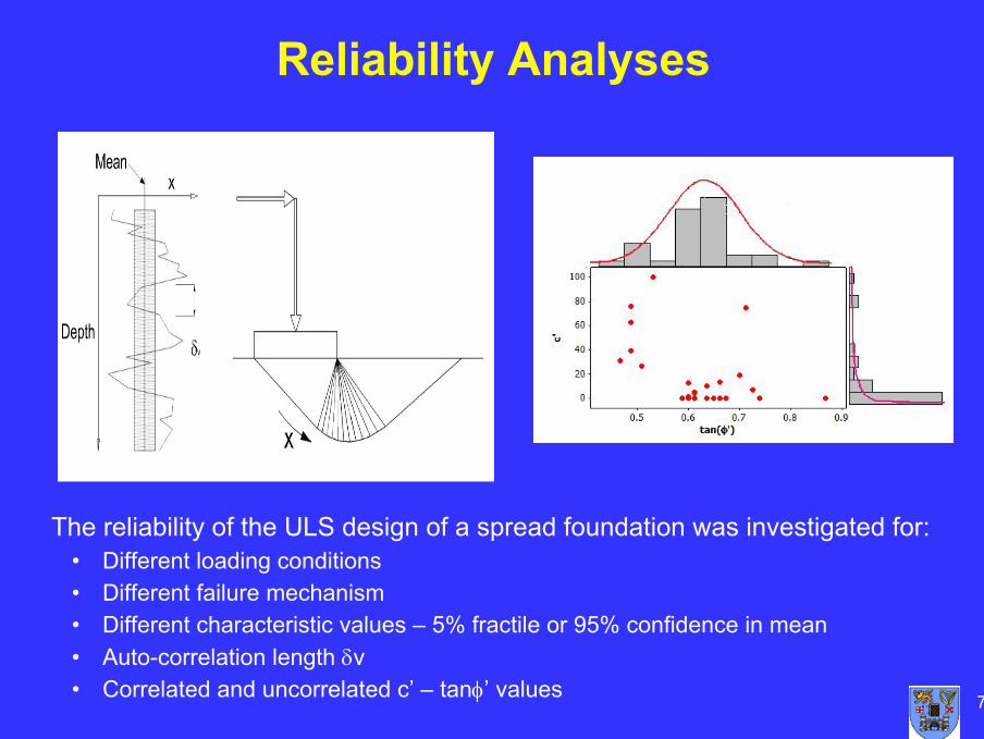
Reliability Analyses
The reliability of the ULS design of a spread foundation was investigated for:• Different loading conditions• Different failure mechanism • Different characteristic values – 5% fractile or 95% confidence in mean• Auto-correlation length δv• Correlated and uncorrelated c’ – tanφ’ values

8
Example Details
• Loading conditions• Results shown for Load Case 1
• FORM analysis and β values
9
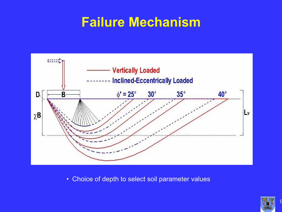
Failure Mechanism
• Choice of depth to select soil parameter values
10
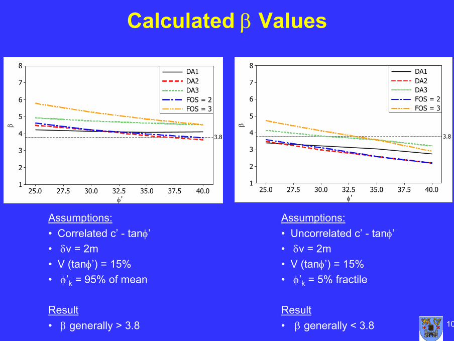
Calculated β Values
40.037.535.032.530.027.525.0
8
7
6
5
4
3
2
1
φ
β
3.8
DA1DA2DA3FOS = 2FOS = 3
'40.037.535.032.530.027.525.0
8
7
6
5
4
3
2
1
φ
β
3.8
DA1DA2DA3FOS = 2FOS = 3
'
Assumptions:• Uncorrelated c’ - tanφ’• δv = 2m• V (tanφ’) = 15%• φ’k = 5% fractile
Result• β generally < 3.8
Assumptions:• Correlated c’ - tanφ’• δv = 2m• V (tanφ’) = 15%• φ’k = 95% of mean
Result• β generally > 3.8

11
Discussion
Any questions
12
Session 4b
Design of Retaining Structures
(Carton House)
13
Scope
• Requirements in Section 9: Retaining Structures of Eurocode 7 apply to structures which retain ground comprising soil, rock or backfill and water at a slope steeper than it would eventually adopt if no structure were present
• Main types are gravity walls and embedded walls
• Eurocode 7 also covers composite walls which are defined in Eurocode 7 as walls as composed of elements from the above two types of wall. A large variety of such walls exists and examples include double sheet pile wall cofferdams, earth structures reinforced by tendons, geotextilesor grouting and structures with multiple rows of ground anchorages or soil nails
• Pressures in silos are not covered by Eurocode 7 but by EN1991-4
14
Relevant CEN Standards
• Eurocode 7 refers to the following CEN standards that are relevant to the design and construction (execution) of retaining walls
• EN 1997-3: Part 53-Pt 5 Design of Steel Structures - Piling (EN 1993-5:1997)
• Execution standard –Execution of special geotechnical work
• EN 1538 - Diaphragm Walls
• EN 12063 - Sheet pile walls
• EN 1536 - Bored Piles
15
Table 9 2
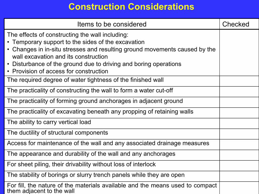
For fill, the nature of the materials available and the means used to compact them adjacent to the wall
The stability of borings or slurry trench panels while they are open
For sheet piling, their drivability without loss of interlock
The appearance and durability of the wall and any anchorages
Access for maintenance of the wall and any associated drainage measures
The ductility of structural components
The ability to carry vertical load
The practicality of excavating beneath any propping of retaining walls
The practicality of forming ground anchorages in adjacent ground
The practicality of constructing the wall to form a water cut-off
The required degree of water tightness of the finished wall
The effects of constructing the wall including:• Temporary support to the sides of the excavation• Changes in in-situ stresses and resulting ground movements caused by the
wall excavation and its construction• Disturbance of the ground due to driving and boring operations• Provision of access for construction
CheckedItems to be considered
Table 9 2
Construction Considerations
16
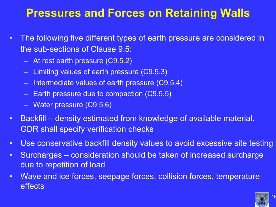
Pressures and Forces on Retaining Walls
• The following five different types of earth pressure are considered in the sub-sections of Clause 9.5:– At rest earth pressure (C9.5.2)– Limiting values of earth pressure (C9.5.3)– Intermediate values of earth pressure (C9.5.4)– Earth pressure due to compaction (C9.5.5)– Water pressure (C9.5.6)
• Backfill – density estimated from knowledge of available material. GDR shall specify verification checks
• Use conservative backfill density values to avoid excessive site testing• Surcharges – consideration should be taken of increased surcharge
due to repetition of load• Wave and ice forces, seepage forces, collision forces, temperature
effects
17
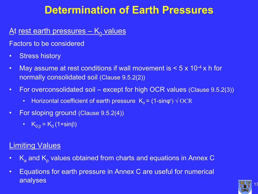
At rest earth pressures – K0 valuesFactors to be considered
• Stress history
• May assume at rest conditions if wall movement is < 5 x 10⁻⁴ x h for normally consolidated soil (Clause 9.5.2(2))
• For overconsolidated soil – except for high OCR values (Clause 9.5.2(3))
• Horizontal coefficient of earth pressure K0 = (1-sinφ') √ OCR
• For sloping ground (Clause 9.5.2(4))
• K0;β = K0 (1+sinβ)
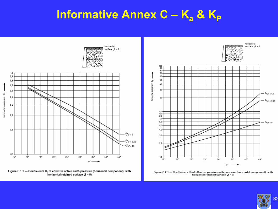
Limiting Values• Ka and Kp values obtained from charts and equations in Annex C
• Equations for earth pressure in Annex C are useful for numericalanalyses
Determination of Earth Pressures
18
Water Pressures
• For silts and clays - The ground water level shall be assumed to be at surface of retained material unless reliable drainage system or infiltration is prevented
• Effects of water filled tension cracks shall be considered where no special drainage or flow prevention measures are installed (principle)
19
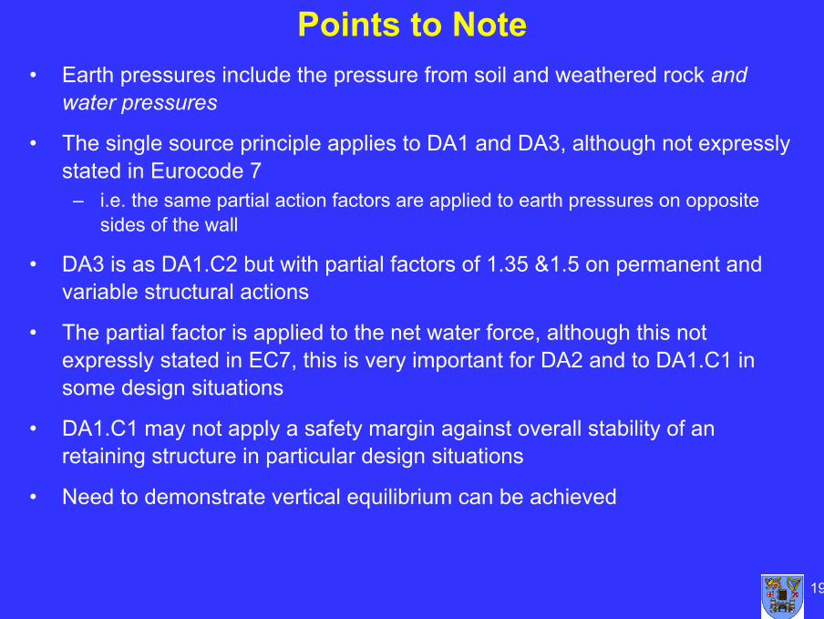
Points to Note• Earth pressures include the pressure from soil and weathered rock and
water pressures
• The single source principle applies to DA1 and DA3, although not expressly stated in Eurocode 7
– i.e. the same partial action factors are applied to earth pressures on opposite sides of the wall
• DA3 is as DA1.C2 but with partial factors of 1.35 &1.5 on permanent and variable structural actions
• The partial factor is applied to the net water force, although this not expressly stated in EC7, this is very important for DA2 and to DA1.C1 in some design situations
• DA1.C1 may not apply a safety margin against overall stability of an retaining structure in particular design situations
• Need to demonstrate vertical equilibrium can be achieved
20
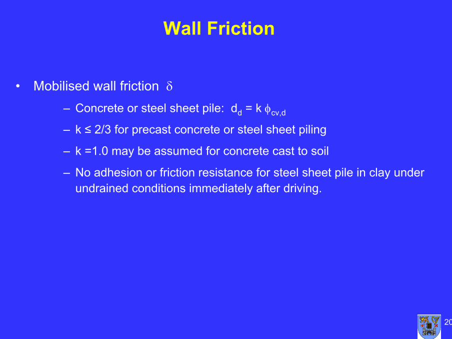
• Mobilised wall friction δ– Concrete or steel sheet pile: dd = k φcv,d
– k ≤ 2/3 for precast concrete or steel sheet piling
– k =1.0 may be assumed for concrete cast to soil
– No adhesion or friction resistance for steel sheet pile in clay under undrained conditions immediately after driving.
Wall Friction
21
Allowance for Unplanned Excavations
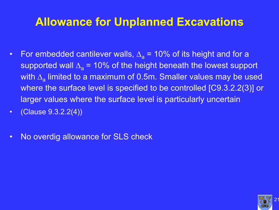
• For embedded cantilever walls, ∆a = 10% of its height and for a supported wall ∆a = 10% of the height beneath the lowest support with ∆a limited to a maximum of 0.5m. Smaller values may be used where the surface level is specified to be controlled [C9.3.2.2(3)] or larger values where the surface level is particularly uncertain
• (Clause 9.3.2.2(4))
• No overdig allowance for SLS check
22
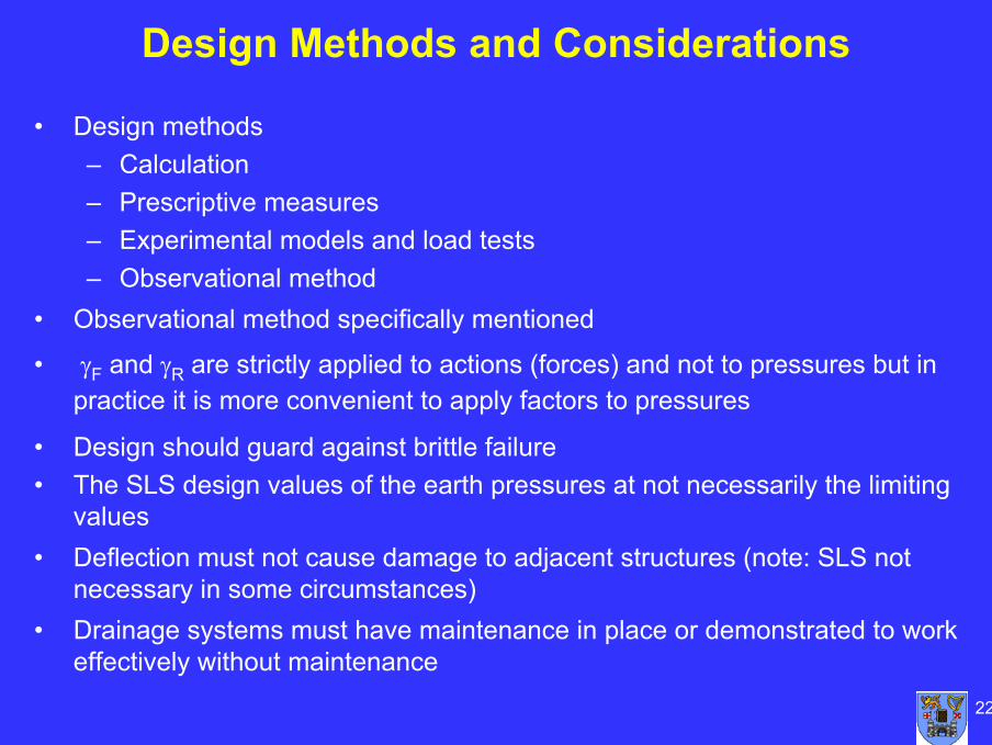
Design Methods and Considerations
• Design methods– Calculation– Prescriptive measures– Experimental models and load tests– Observational method
• Observational method specifically mentioned
• γF and γR are strictly applied to actions (forces) and not to pressures but in practice it is more convenient to apply factors to pressures
• Design should guard against brittle failure• The SLS design values of the earth pressures at not necessarily the limiting
values• Deflection must not cause damage to adjacent structures (note: SLS not
necessary in some circumstances)• Drainage systems must have maintenance in place or demonstrated to work
effectively without maintenance
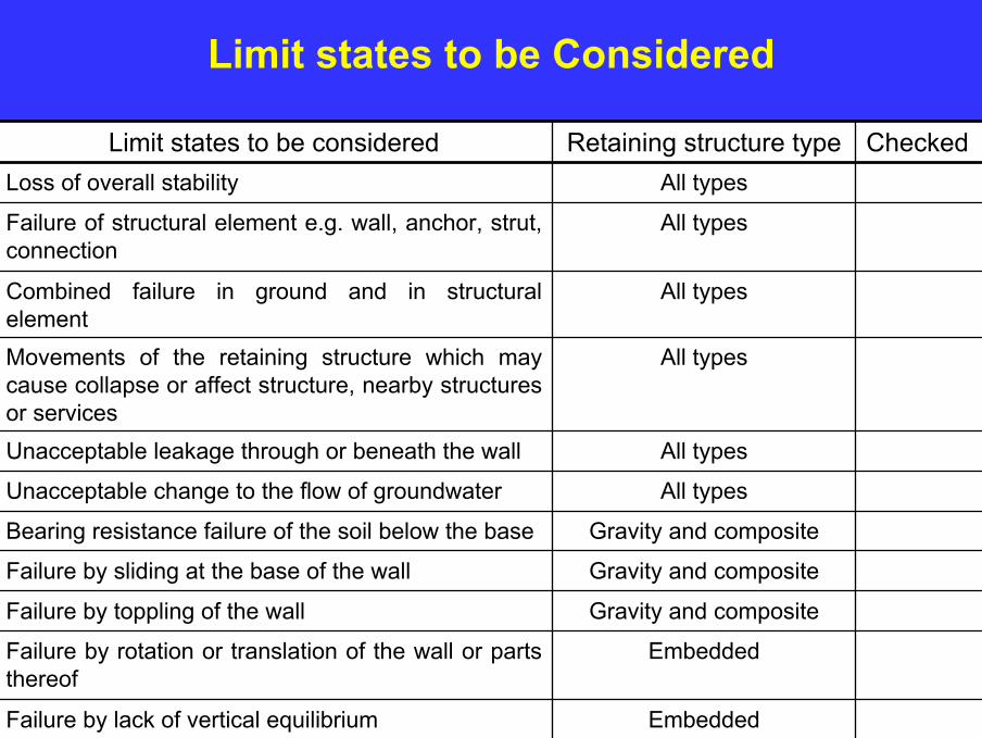
23EmbeddedFailure by lack of vertical equilibrium
EmbeddedFailure by rotation or translation of the wall or parts thereof
Gravity and compositeFailure by toppling of the wall
Gravity and compositeFailure by sliding at the base of the wall
Gravity and compositeBearing resistance failure of the soil below the base
All typesUnacceptable change to the flow of groundwater
All typesUnacceptable leakage through or beneath the wall
All typesMovements of the retaining structure which may cause collapse or affect structure, nearby structures or services
All typesCombined failure in ground and in structural element
All typesFailure of structural element e.g. wall, anchor, strut, connection
All typesLoss of overall stability
CheckedRetaining structure typeLimit states to be considered
Limit states to be Considered
24
Actions and Resistances
Geotechnical Action• Eurocode 7 defines a geotechnical action as an action transmitted to the
structure by the ground, fill, standing water or ground-water (Clause 1.5.2.1)
Passive Earth Pressure• The passive earth pressure, PP acting on resistance side of a gravity wall
should be considered as an earth resistance (Table A.13) when considering base sliding and as a favourable geotechnical action (Table A3) when considering bearing failure
Design water levels/pressures• The design value of the water table is generally taken as the worst
reasonable scenario. An alternative approach is to consider the variations in the water level as a variable action and the apply appropriate partial factor
25
Design Actions
DA1.C1 & DA2• In DA1.C1 and DA2, design values of action are obtained by applying γF to the
characteristic values of non geotechnical actions e.g. self weight of the wall Fd = γF Fkand to geotechnical actions obtained from the characteristic values of the ground parameters Fd = γFF(Xk) or alternatively to the effect of actions Ed = γEE(Fk,Xk,ad)
DA1.C2 & DA3• In DA1.C2 and DA3, design values are obtained by applying γF to the characteristic
values of non geotechnical actions Fd = γF Fk and the design values of geotechnical actions are obtained by factoring the ground parameters Fd = γF F(Xk / γm)
Effects of actions• Where the application of the partial values to geotechnical actions gives
unreasonable results, the partial factors for actions can be applied directly to the effect of actions, e.g. BM or SF, calculated using representative values of the actions(Clause 2.4.7.3.2(2))
26
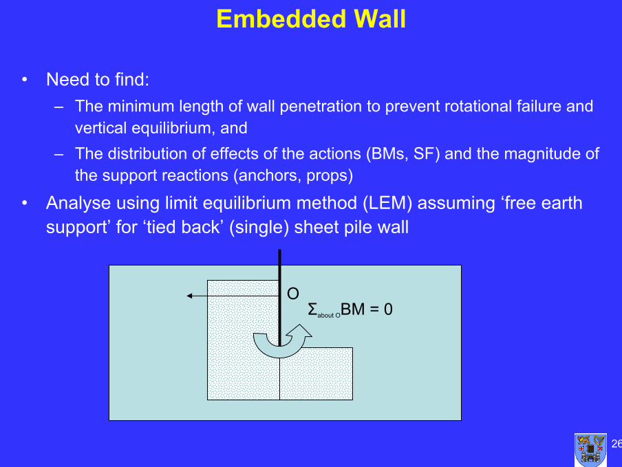
Embedded Wall
OΣabout OBM = 0
• Need to find:– The minimum length of wall penetration to prevent rotational failure and
vertical equilibrium, and– The distribution of effects of the actions (BMs, SF) and the magnitude of
the support reactions (anchors, props)
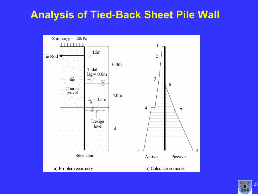
• Analyse using limit equilibrium method (LEM) assuming ‘free earth support’ for ‘tied back’ (single) sheet pile wall
27
Analysis of Tied-Back Sheet Pile Wall
6.0m
4.0m
d
∆ = 0.5m
a) Problem geometry
Silty sand
levelDesign
d
gravelCoarse
Surcharge = 20kPa
Tie Rod
Tidallag = 0.6m
1.5m
8Active
b) Calculation model
4
5Passive
7
3
1
2
6
28
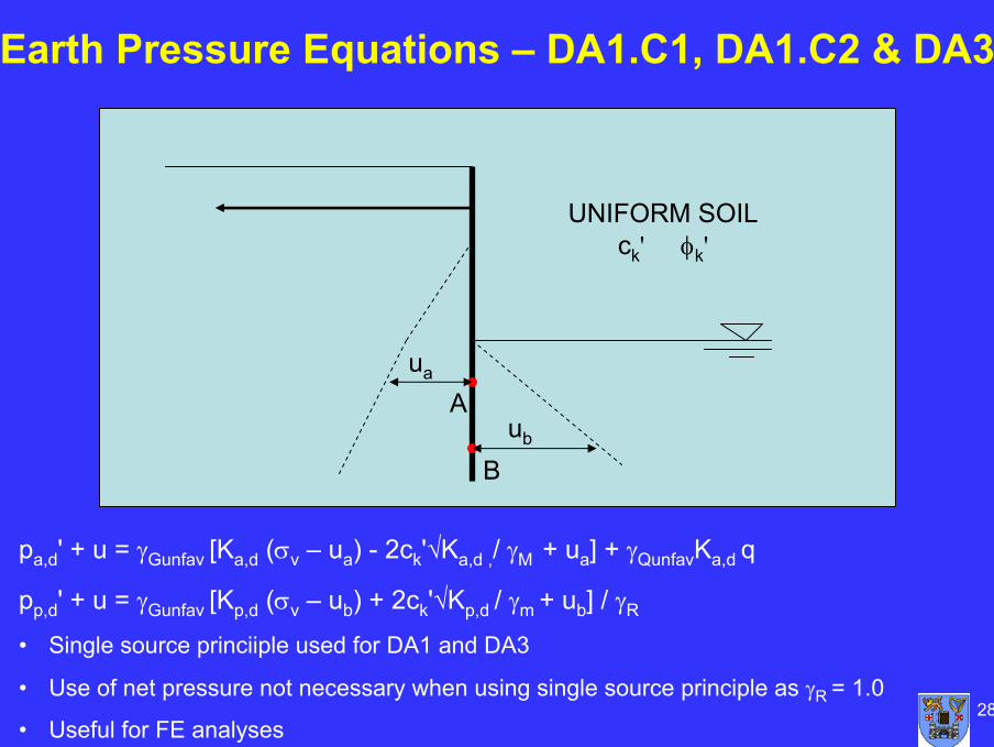
Earth Pressure Equations – DA1.C1, DA1.C2 & DA3
pa,d' + u = γGunfav [Ka,d (σv – ua) - 2ck'√Ka,d ,/ γM + ua] + γQunfavKa,d q
pp,d' + u = γGunfav [Kp,d (σv – ub) + 2ck'√Kp,d / γm + ub] / γR
• Single source princiiple used for DA1 and DA3
• Use of net pressure not necessary when using single source principle as γR = 1.0
• Useful for FE analyses
Aua
UNIFORM SOIL ck' φk'
Bub
29
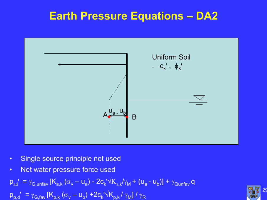
Earth Pressure Equations – DA2
• Single source principle not used• Net water pressure force used
pad' = γG,unfav [Ka,k (σv – ua) - 2ck'√Ka,k/γM + (ua - ub)] + γQunfav q
pp,d' = γG,fav [Kp,k (σv – ub) +2ck'√Kp,k / γM] / γR
Aua - ub
Uniform Soil . ck' , φk'
B
30
Calculation Stages
• Compute the design earth pressure
• Determine the sheet pile length by taking moments about the tie rod
• Determine the design tie rod force by balancing horizontal forces
• Determine the bending moments using the design earth pressure values.
31
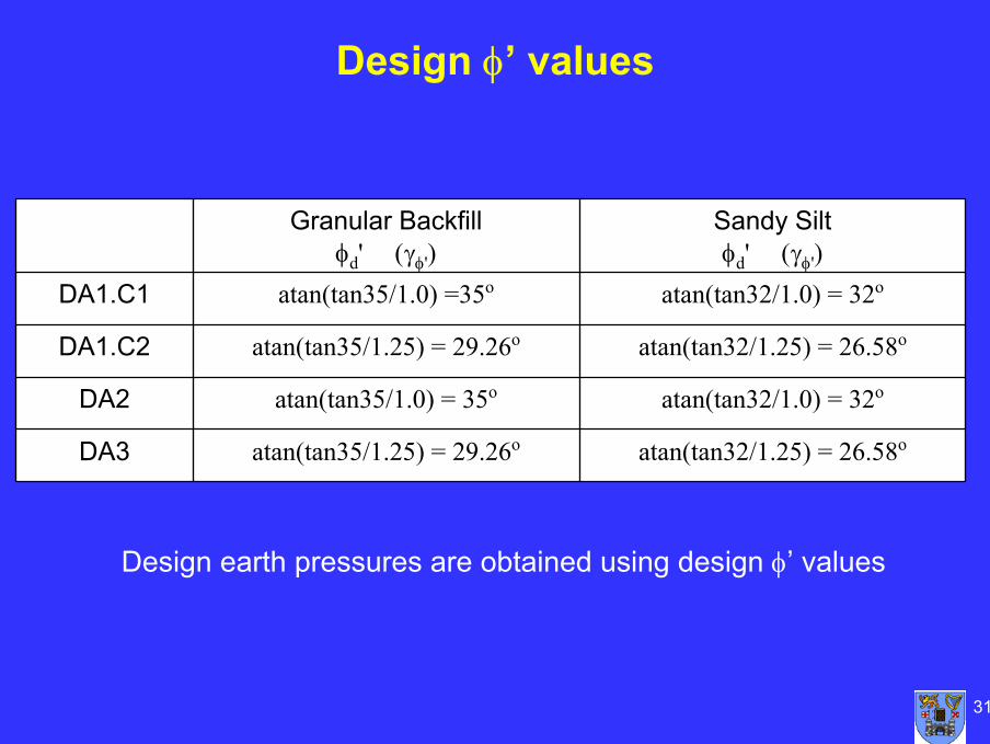
Design φ’ values
DA3 M3 γcu=1.4; γc'=1.25; γφ'=1.25
atan(tan32/1.25) = 26.58oatan(tan35/1.25) = 29.26oDA3
atan(tan32/1.0) = 32oatan(tan35/1.0) = 35oDA2
atan(tan32/1.25) = 26.58oatan(tan35/1.25) = 29.26oDA1.C2
atan(tan32/1.0) = 32oatan(tan35/1.0) =35oDA1.C1
Sandy Siltφd' (γφ')
Granular Backfillφd' (γφ')
Design earth pressures are obtained using design φ’ values
32
Informative Annex C – Ka & KP
33
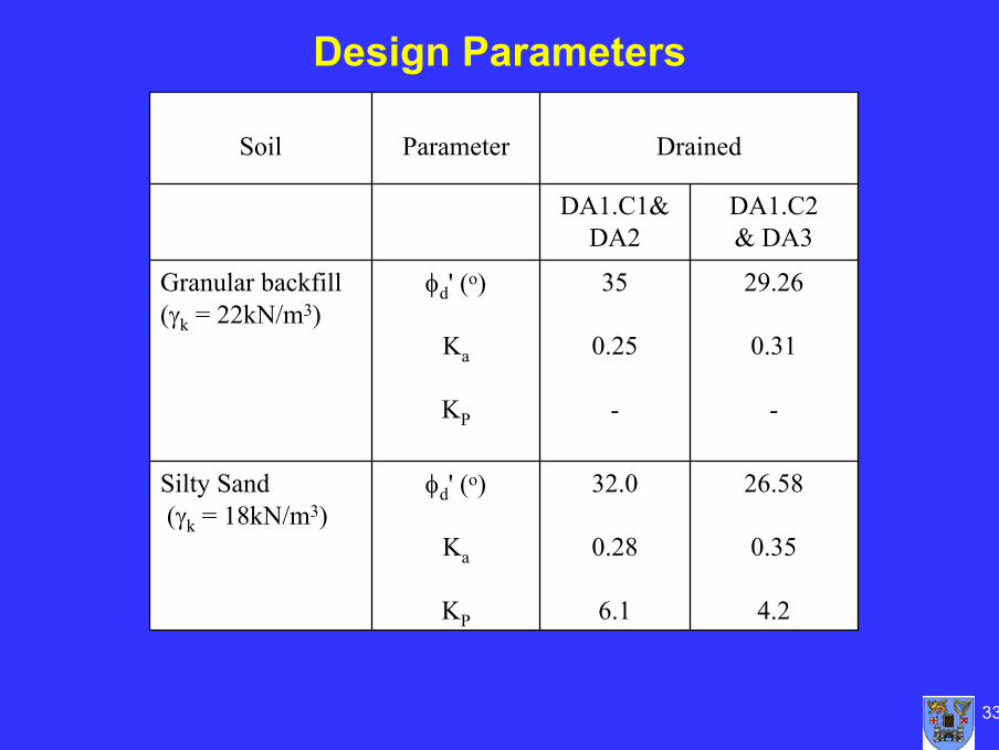
26.58
0.35
4.2
32.0
0.28
6.1
φd' (o)
Ka
KP
Silty Sand(γk = 18kN/m3)
29.26
0.31
-
35
0.25
-
φd' (o)
Ka
KP
Granular backfill(γk = 22kN/m3)
DA1.C2& DA3
DA1.C1& DA2
DrainedParameterSoil
Design Parameters
34
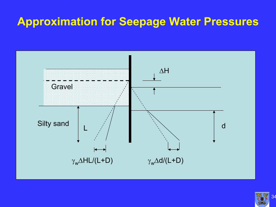
Approximation for Seepage Water Pressures
Gravel
Silty sand d
∆H
L
γw∆HL/(L+D) γw∆d/(L+D)
35
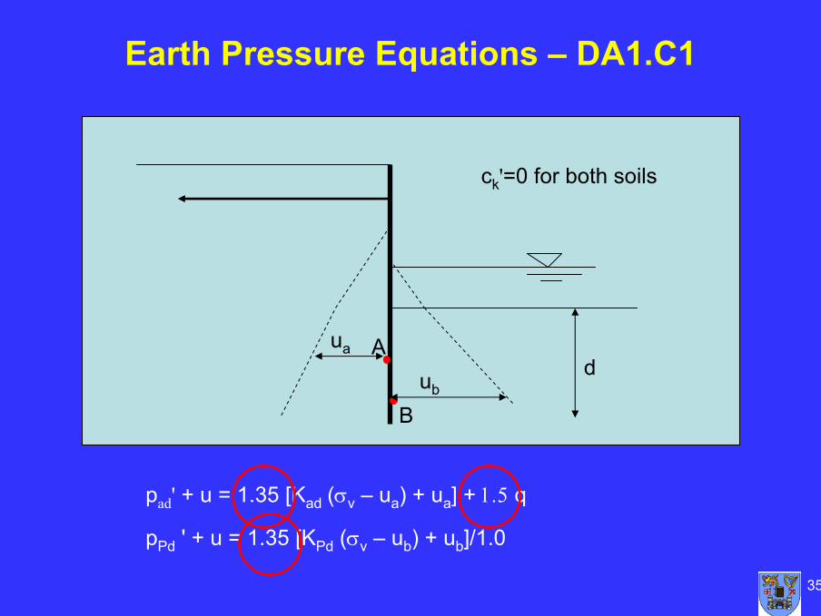
Earth Pressure Equations – DA1.C1
pad' + u = 1.35 [Kad (σv – ua) + ua] + 1.5 q
pPd ' + u = 1.35 [KPd (σv – ub) + ub]/1.0
Aua
Bub
ck'=0 for both soils
d
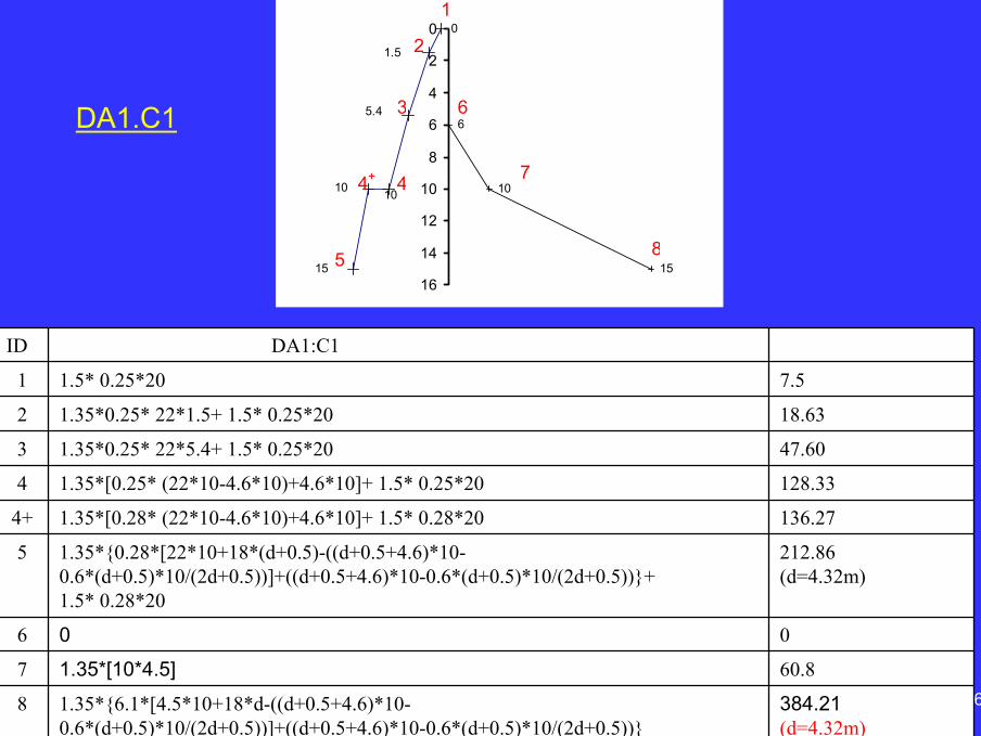
361.35*{6.1*[4.5*10+18*d-((d+0.5+4.6)*10-0.6*(d+0.5)*10/(2d+0.5))]+((d+0.5+4.6)*10-0.6*(d+0.5)*10/(2d+0.5))}
1.35*[10*4.5]
0
1.35*{0.28*[22*10+18*(d+0.5)-((d+0.5+4.6)*10-0.6*(d+0.5)*10/(2d+0.5))]+((d+0.5+4.6)*10-0.6*(d+0.5)*10/(2d+0.5))}+1.5* 0.28*20
1.35*[0.28* (22*10-4.6*10)+4.6*10]+ 1.5* 0.28*20
1.35*[0.25* (22*10-4.6*10)+4.6*10]+ 1.5* 0.25*20
1.35*0.25* 22*5.4+ 1.5* 0.25*20
1.35*0.25* 22*1.5+ 1.5* 0.25*20
1.5* 0.25*20
DA1:C1
384.21(d=4.32m)
8
60.87
06
212.86(d=4.32m)
5
136.274+
128.334
47.603
18.632
7.51
ID
0
6
10
1515
1.5
5.4
1010
0
2
4
6
8
10
12
14
16
-150 -100 -50 0 50 100 150 200 2501
2
3
44+
5
6
7
8
DA1.C1
37
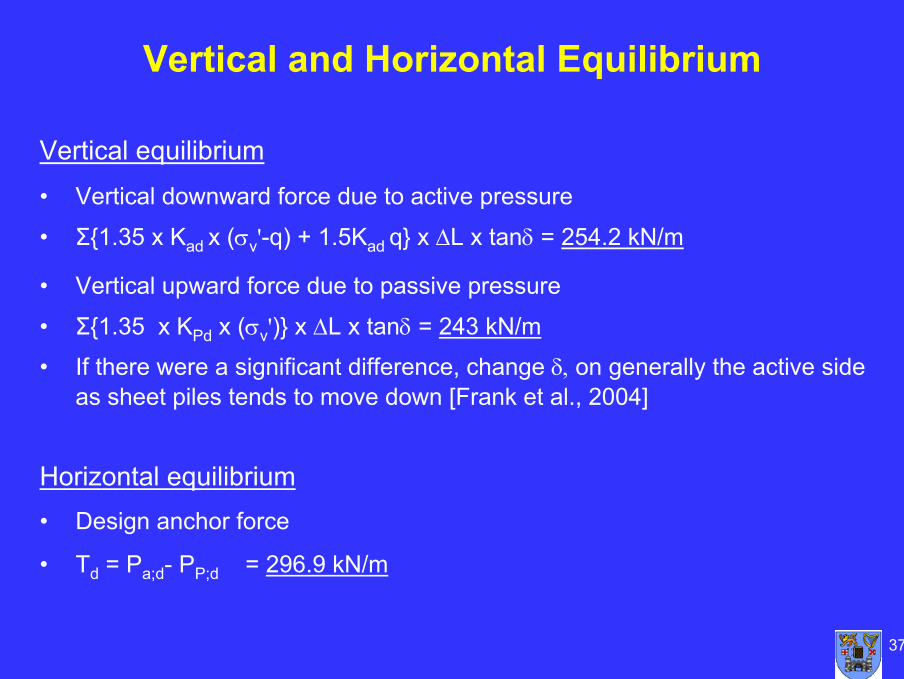
Vertical equilibrium
• Vertical downward force due to active pressure
• Σ{1.35 x Kad x (σv'-q) + 1.5Kad q} x ∆L x tanδ = 254.2 kN/m
• Vertical upward force due to passive pressure
• Σ{1.35 x KPd x (σv')} x ∆L x tanδ = 243 kN/m
• If there were a significant difference, change δ, on generally the active side as sheet piles tends to move down [Frank et al., 2004]
Horizontal equilibrium• Design anchor force
• Td = Pa;d- PP;d = 296.9 kN/m
Vertical and Horizontal Equilibrium
38
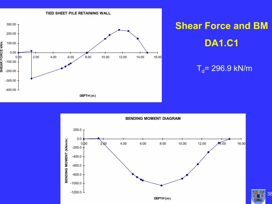
TIED SHEET PILE RETAINING WALL
-400.00
-300.00
-200.00
-100.00
0.00
100.00
200.00
300.00
0.00 2.00 4.00 6.00 8.00 10.00 12.00 14.00 16.00
DEPTH (m)
SHEA
R F
OR
CE
kN/m
BENDING MOMENT DIAGRAM
-1200.0
-1000.0
-800.0
-600.0
-400.0
-200.0
0.0
200.0
0.00 2.00 4.00 6.00 8.00 10.00 12.00 14.00 16.00
DEPTH (m)
BEN
DIN
G M
OM
ENT
(kN
m/m
)
Shear Force and BM
DA1.C1
Td= 296.9 kN/m
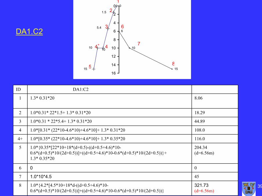
391.0*{4.2*[4.5*10+18*d-((d+0.5+4.6)*10-0.6*(d+0.5)*10/(2d+0.5))]+((d+0.5+4.6)*10-0.6*(d+0.5)*10/(2d+0.5))}
1.0*10*4.5
0
1.0*{0.35*[22*10+18*(d+0.5)-((d+0.5+4.6)*10-0.6*(d+0.5)*10/(2d+0.5))]+((d+0.5+4.6)*10-0.6*(d+0.5)*10/(2d+0.5))}+1.3* 0.35*20
1.0*[0.35* (22*10-4.6*10)+4.6*10]+ 1.3* 0.35*20
1.0*[0.31* (22*10-4.6*10)+4.6*10]+ 1.3* 0.31*20
1.0*0.31 * 22*5.4+ 1.3* 0.31*20
1.0*0.31* 22*1.5+ 1.3* 0.31*20
1.3* 0.31*20
DA1:C2
321.73(d=6.56m)
8
457
06
204.34(d=6.56m)
5
116.04+
108.04
44.893
18.292
8.061
ID
0
6
10
1515
1.5
5.4
1010
0
2
4
6
8
10
12
14
16
-150 -100 -50 0 50 100 150 200 2501
2
3
44+
5
6
7
8
DA1.C2
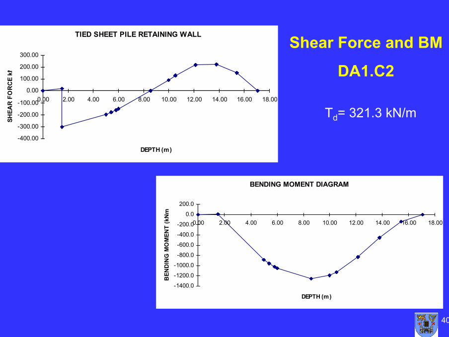
40
Td= 321.3 kN/m
TIED SHEET PILE RETAINING WALL
-400.00
-300.00
-200.00
-100.00
0.00
100.00
200.00
300.00
0.00 2.00 4.00 6.00 8.00 10.00 12.00 14.00 16.00 18.00
DEPTH (m)
SHEA
R F
OR
CE
kN
BENDING MOMENT DIAGRAM
-1400.0
-1200.0
-1000.0
-800.0
-600.0
-400.0
-200.0
0.0
200.0
0.00 2.00 4.00 6.00 8.00 10.00 12.00 14.00 16.00 18.00
DEPTH (m)
BEN
DIN
G M
OM
ENT
(kN
m
Shear Force and BM
DA1.C2
41
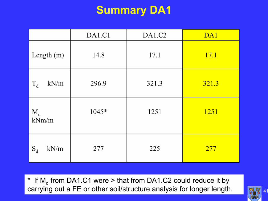
Summary DA1
277225277Sd kN/m
125112511045*MdkNm/m
321.3321.3296.9Td kN/m
17.117.114.8Length (m)
DA1DA1.C2DA1.C1
* If Md from DA1.C1 were > that from DA1.C2 could reduce it by carrying out a FE or other soil/structure analysis for longer length.
42
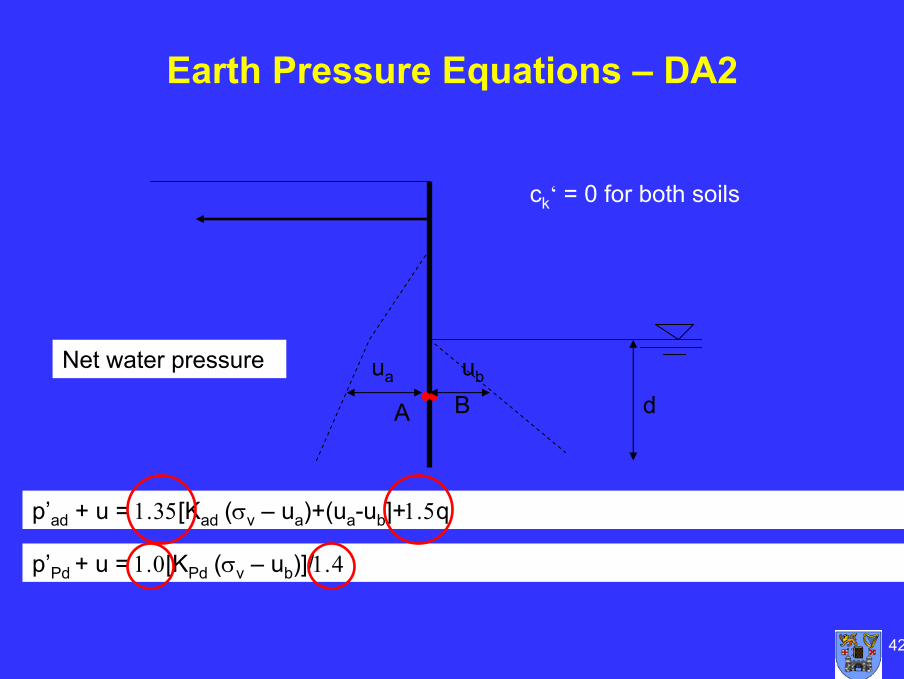
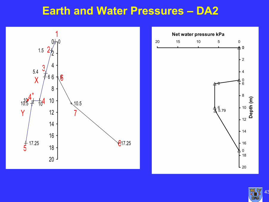
Earth Pressure Equations – DA2
p’ad + u = 1.35[Kad (σv – ua)+(ua-ub]+1.5q
A
ua
Bub
p’Pd + u = 1.0[KPd (σv – ub)]/1.4
ck‘ = 0 for both soils
d
Net water pressure
43
0
06
65.79
0
0
2
4
6
8
10
12
14
16
18
20
05101520
Net water pressure kPa
Dep
th (m
)
0
6
17.25
6
10.5
17.25
10.5
1.5
5.4
1010
0
2
4
6
8
10
12
14
16
18
20
-150 -100 -50 0 50 100 150 200 2501
2
3
44+
5
6
7
8
X
Y
Earth and Water Pressures – DA2
44
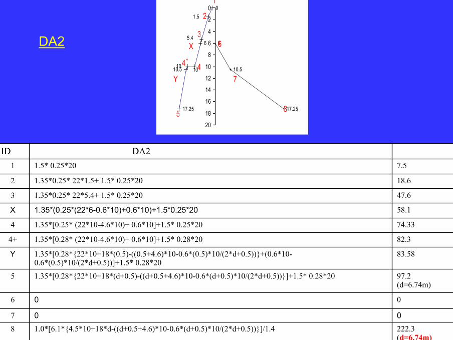
58.11.35*(0.25*(22*6-0.6*10)+0.6*10)+1.5*0.25*20X
222.3(d=6.74m)
1.0*[6.1*{4.5*10+18*d-((d+0.5+4.6)*10-0.6*(d+0.5)*10/(2*d+0.5))}]/1.48
0
0
1.35*[0.28*{22*10+18*(d+0.5)-((d+0.5+4.6)*10-0.6*(d+0.5)*10/(2*d+0.5))}]+1.5* 0.28*20
1.35*[0.28*{22*10+18*(0.5)-((0.5+4.6)*10-0.6*(0.5)*10/(2*d+0.5))}+(0.6*10-0.6*(0.5)*10/(2*d+0.5))]+1.5* 0.28*20
1.35*[0.28* (22*10-4.6*10)+ 0.6*10]+1.5* 0.28*20
1.35*[0.25* (22*10-4.6*10)+ 0.6*10]+1.5* 0.25*20
1.35*0.25* 22*5.4+ 1.5* 0.25*20
1.35*0.25* 22*1.5+ 1.5* 0.25*20
1.5* 0.25*20
DA2
07
06
97.2(d=6.74m)
5
83.58Y
82.34+
74.334
47.63
18.62
7.51
ID
0
6
17.25
6
10.5
17.25
10.5
1.5
5.4
1010
0
2
4
6
8
10
12
14
16
18
20
-150 -100 -50 0 50 100 150 200 2501
2
3
44+
5
6
7
8
X
Y
DA2
45
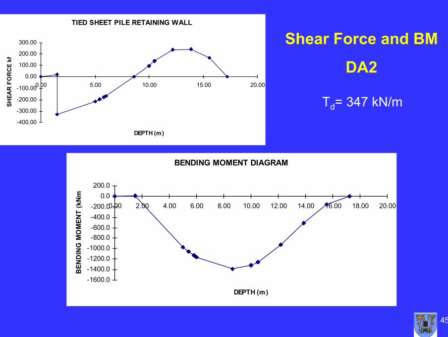
TIED SHEET PILE RETAINING WALL
-400.00
-300.00
-200.00
-100.00
0.00
100.00
200.00
300.00
0.00 5.00 10.00 15.00 20.00
DEPTH (m)
SHEA
R F
OR
CE
kN
BENDING MOMENT DIAGRAM
-1600.0-1400.0-1200.0-1000.0-800.0-600.0-400.0-200.0
0.0200.0
0.00 2.00 4.00 6.00 8.00 10.00 12.00 14.00 16.00 18.00 20.00
DEPTH (m)
BEN
DIN
G M
OM
ENT
(kN
m
Shear Force and BM
DA2
Td= 347 kN/m
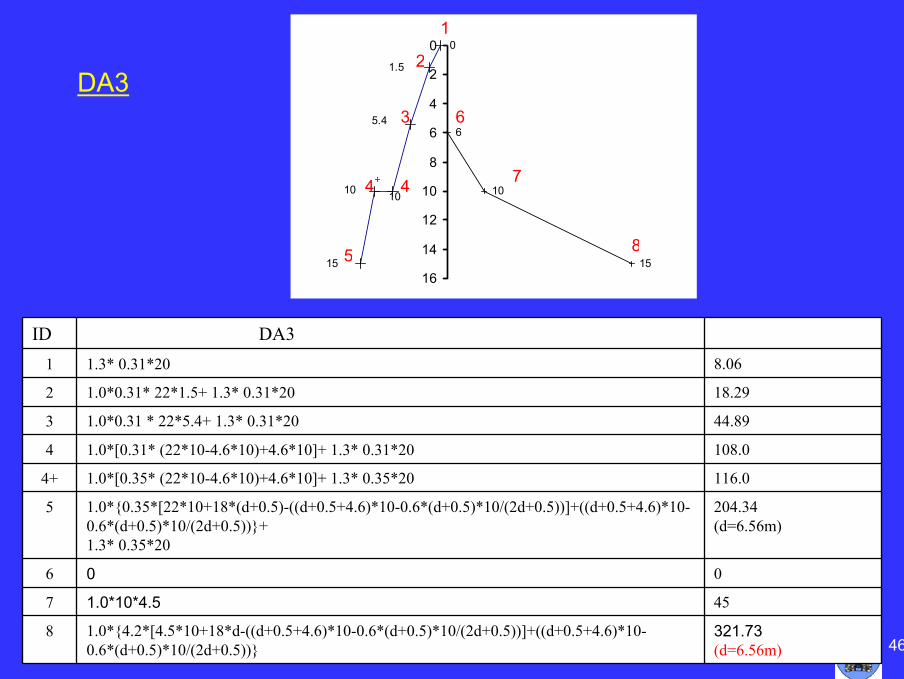
461.0*{4.2*[4.5*10+18*d-((d+0.5+4.6)*10-0.6*(d+0.5)*10/(2d+0.5))]+((d+0.5+4.6)*10-0.6*(d+0.5)*10/(2d+0.5))}
1.0*10*4.5
0
1.0*{0.35*[22*10+18*(d+0.5)-((d+0.5+4.6)*10-0.6*(d+0.5)*10/(2d+0.5))]+((d+0.5+4.6)*10-0.6*(d+0.5)*10/(2d+0.5))}+1.3* 0.35*20
1.0*[0.35* (22*10-4.6*10)+4.6*10]+ 1.3* 0.35*20
1.0*[0.31* (22*10-4.6*10)+4.6*10]+ 1.3* 0.31*20
1.0*0.31 * 22*5.4+ 1.3* 0.31*20
1.0*0.31* 22*1.5+ 1.3* 0.31*20
1.3* 0.31*20
DA3
321.73(d=6.56m)
8
457
06
204.34(d=6.56m)
5
116.04+
108.04
44.893
18.292
8.061
ID
0
6
10
1515
1.5
5.4
1010
0
2
4
6
8
10
12
14
16
-150 -100 -50 0 50 100 150 200 2501
2
3
44+
5
6
7
8
DA3
47
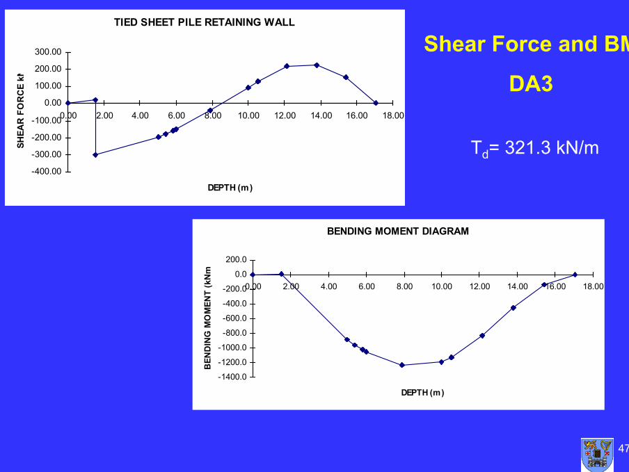
TIED SHEET PILE RETAINING WALL
-400.00
-300.00
-200.00
-100.00
0.00
100.00
200.00
300.00
0.00 2.00 4.00 6.00 8.00 10.00 12.00 14.00 16.00 18.00
DEPTH (m)
SHEA
R F
OR
CE
kN
BENDING MOMENT DIAGRAM
-1400.0
-1200.0
-1000.0
-800.0
-600.0
-400.0
-200.0
0.0
200.0
0.00 2.00 4.00 6.00 8.00 10.00 12.00 14.00 16.00 18.00
DEPTH (m)
BEN
DIN
G M
OM
ENT
(kN
m
Shear Force and BM
DA3
Td= 321.3 kN/m
48
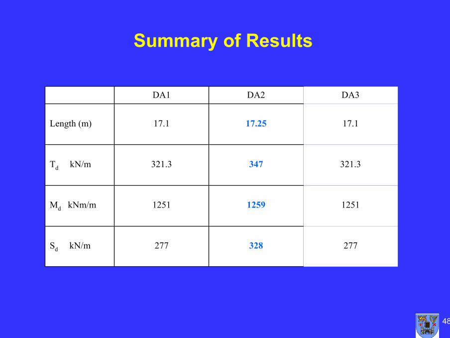
277328277Sd kN/m
125112591251Md kNm/m
321.3347321.3Td kN/m
17.117.2517.1Length (m)
DA3DA2DA1
Summary of Results
49
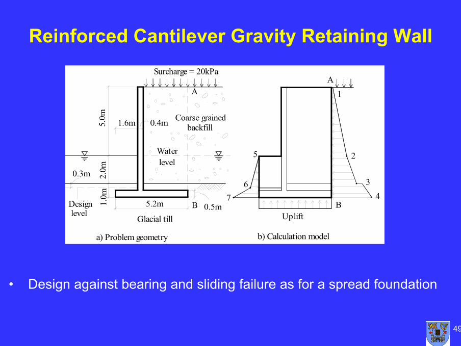
Reinforced Cantilever Gravity Retaining Wall
Coarse grained backfill
Surcharge = 20kPa
0.5m1.0m
a) Problem geometry
levelDesign B
Glacial till
5.2m
1.6m5.0m
2.0m0.3m
Waterlevel
A
0.4m
7 4
Uplift
b) Calculation model
B
6
5
1
2
3
A
• Design against bearing and sliding failure as for a spread foundation

50
Discussion
Any Questions
51
Session 4c
Slopes, Overall Stability and Embankments
52
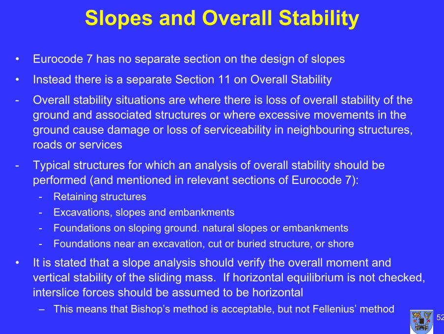
Slopes and Overall Stability
• Eurocode 7 has no separate section on the design of slopes
• Instead there is a separate Section 11 on Overall Stability
- Overall stability situations are where there is loss of overall stability of the ground and associated structures or where excessive movements in the ground cause damage or loss of serviceability in neighbouring structures, roads or services
- Typical structures for which an analysis of overall stability should be performed (and mentioned in relevant sections of Eurocode 7):
- Retaining structures- Excavations, slopes and embankments- Foundations on sloping ground. natural slopes or embankments- Foundations near an excavation, cut or buried structure, or shore
• It is stated that a slope analysis should verify the overall moment and vertical stability of the sliding mass. If horizontal equilibrium is not checked, interslice forces should be assumed to be horizontal
– This means that Bishop’s method is acceptable, but not Fellenius’ method
53
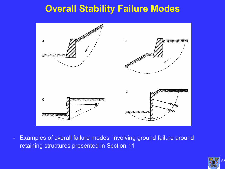
Overall Stability Failure Modes
- Examples of overall failure modes involving ground failure around retaining structures presented in Section 11
54
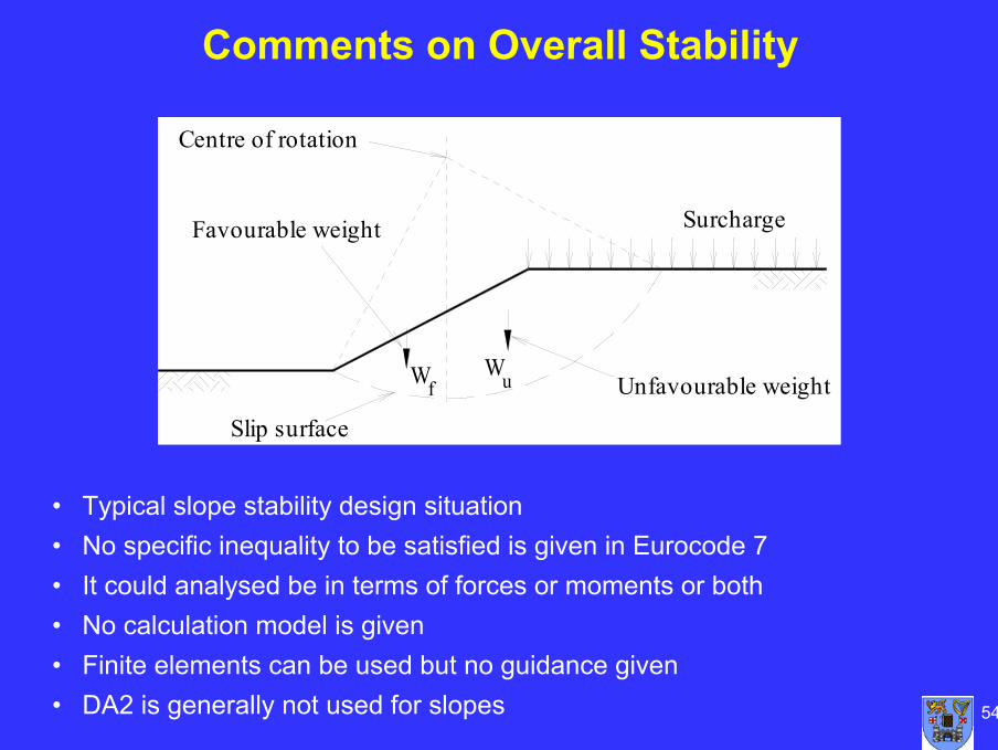
Comments on Overall Stability
Unfavourable weight
SurchargeFavourable weight
Centre of rotation
Wf
Slip surface
Wu
• Typical slope stability design situation• No specific inequality to be satisfied is given in Eurocode 7• It could analysed be in terms of forces or moments or both• No calculation model is given• Finite elements can be used but no guidance given• DA2 is generally not used for slopes
55
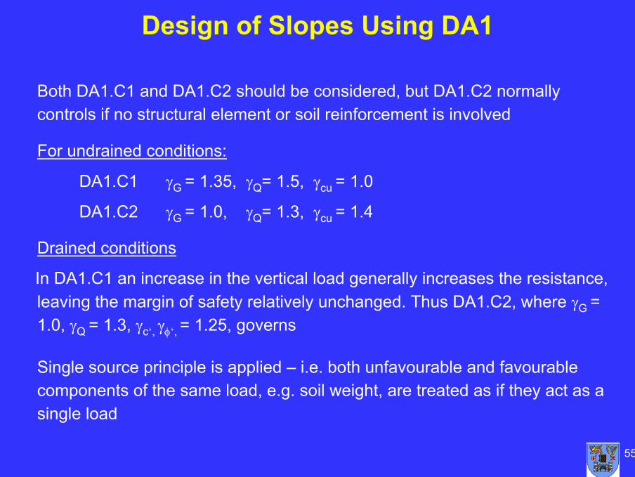
Design of Slopes Using DA1
Both DA1.C1 and DA1.C2 should be considered, but DA1.C2 normallycontrols if no structural element or soil reinforcement is involved
For undrained conditions:
DA1.C1 γG = 1.35, γQ= 1.5, γcu = 1.0
DA1.C2 γG = 1.0, γQ= 1.3, γcu = 1.4
Drained conditions
In DA1.C1 an increase in the vertical load generally increases the resistance, leaving the margin of safety relatively unchanged. Thus DA1.C2, where γG = 1.0, γQ = 1.3, γc‘, γφ‘, = 1.25, governs
Single source principle is applied – i.e. both unfavourable and favourable components of the same load, e.g. soil weight, are treated as if they act as a single load
56
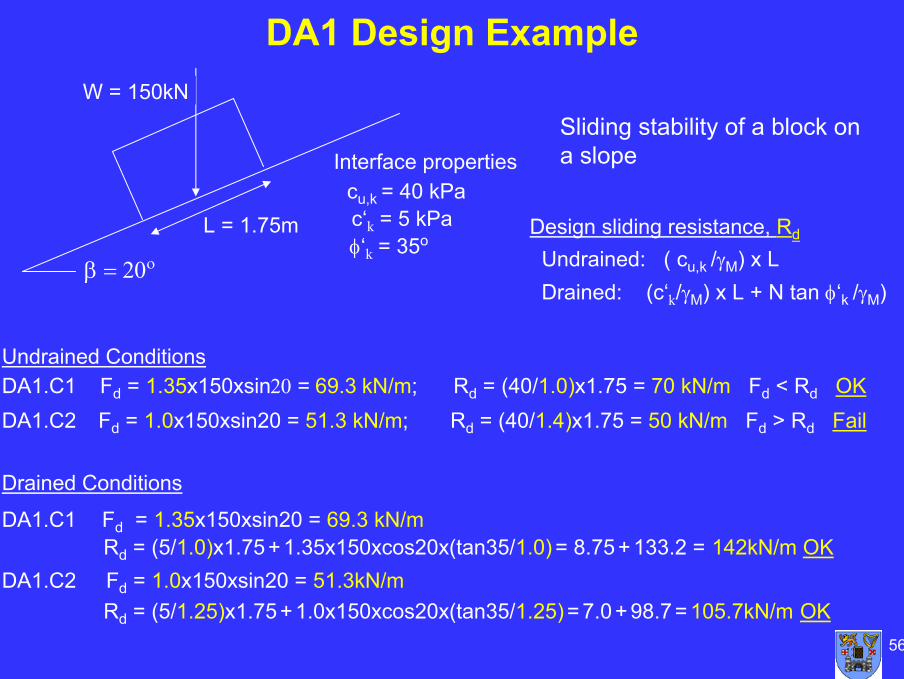
W = 150kN
β = 20ο
Interface propertiescu,k = 40 kPac‘k = 5 kPaφ‘k = 35o
Undrained ConditionsDA1.C1 Fd = 1.35x150xsin20 = 69.3 kN/m; Rd = (40/1.0)x1.75 = 70 kN/m Fd < Rd OKDA1.C2 Fd = 1.0x150xsin20 = 51.3 kN/m; Rd = (40/1.4)x1.75 = 50 kN/m Fd > Rd Fail
Drained Conditions
DA1.C1 Fd = 1.35x150xsin20 = 69.3 kN/mRd = (5/1.0)x1.75 +1.35x150xcos20x(tan35/1.0) = 8.75 + 133.2 = 142kN/m OK
DA1.C2 Fd = 1.0x150xsin20 = 51.3kN/mRd = (5/1.25)x1.75 +1.0x150xcos20x(tan35/1.25) = 7.0 + 98.7= 105.7kN/m OK
L = 1.75m
DA1 Design Example
Sliding stability of a block on a slope
Design sliding resistance, Rd
Undrained: ( cu,k /γM) x LDrained: (c‘k/γM) x L + N tan φ‘k /γM)
57
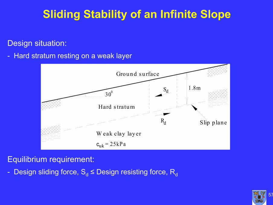
Sliding Stability of an Infinite Slope
S
Rd
d
Ground s u rface
W eak clay layer
Slip p lane
1.8m
c = 25kP auk
30
Hard s tratum
0
Design situation:- Hard stratum resting on a weak layer
Equilibrium requirement:- Design sliding force, Sd ≤ Design resisting force, Rd

58
Infinite Slope with Seepage
β
Slip plane
β
hz
bcos
b
For water table at the surface:
Traditional design
βγφγ
tan'tan'
sat
F =
If F = 1.25
γsat tan β ≤ γ’ (tanφ’/ 1.25)
i.e Eurocode 7 condition

59
Slope Stability Analysis Using Method of Slices
0
5
10
15
20
25
30
35
40
0 10 20 30 40 50 60 70 80
x Axis
y A
xis
Radius, r
Eurocode 7 requirements when using the method of slices:- Both vertical and moment equilibrium should be checked, and- If horizontal equilibrium is not checked, then the interslice forces shall
be assumed to be horizontal- This means some simpler methods not acceptable
Centre of rotation
60
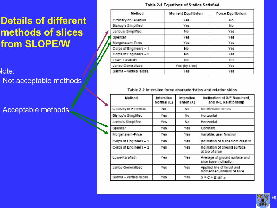
Details of different methods of slices from SLOPE/W
Note:- Not acceptable methods
- Acceptable methods
61
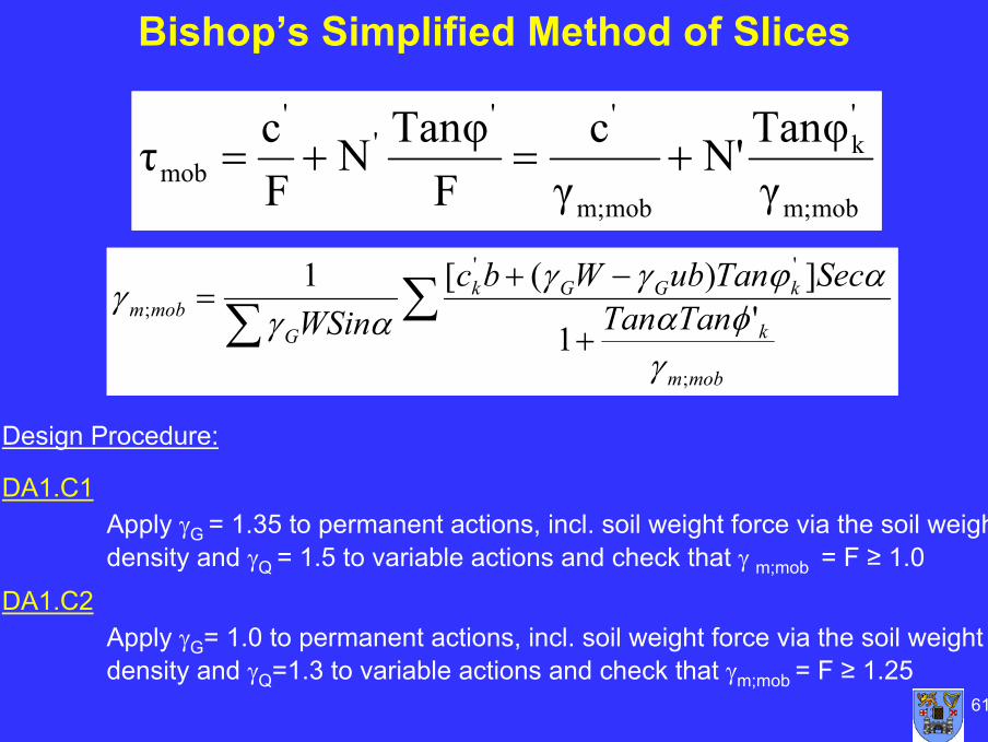
Bishop’s Simplified Method of Slices
mobm;
'k
mobm;
'''
'
mob γTanφN'
γc
FTanφN
Fcτ +=+=
Design Procedure:
DA1.C1Apply γG = 1.35 to permanent actions, incl. soil weight force via the soil weight density and γQ = 1.5 to variable actions and check that γ m;mob = F ≥ 1.0
DA1.C2Apply γG= 1.0 to permanent actions, incl. soil weight force via the soil weight density and γQ=1.3 to variable actions and check that γm;mob = F ≥ 1.25
∑∑ +
−+=
mobm
k
kGGk
Gmobm TanTan
SecTanubWbcWSin
;
''
; '1
])([1
γφα
αϕγγαγ
γ
62
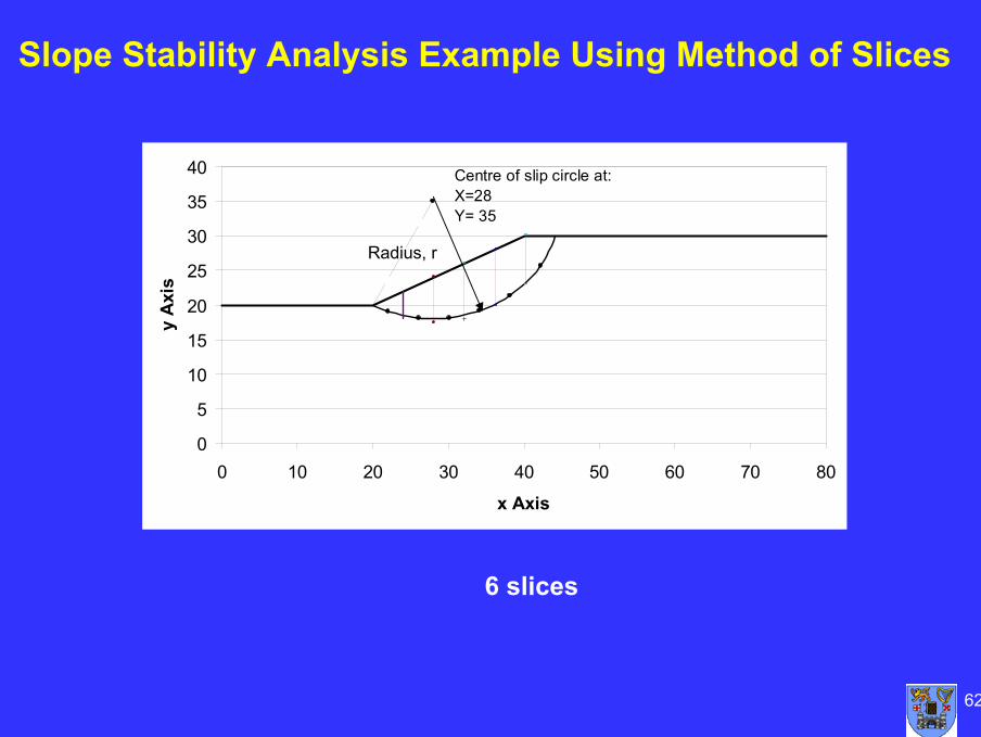
Slope Stability Analysis Example Using Method of Slices
0
5
10
15
20
25
30
35
40
0 10 20 30 40 50 60 70 80
x Axis
y A
xisCentre of slip circle at:X=28Y= 35
Radius, r
6 slices
63
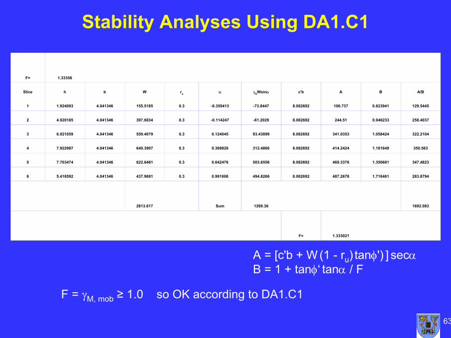
Stability Analyses Using DA1.C1
F = γM, mob ≥ 1.0 so OK according to DA1.C1
1.333021F=
1692.0831269.36Sum2813.617
283.87941.716461487.26788.082692494.82660.9916060.3437.96814.0413465.4185926
347.48231.350681469.33768.082692503.65560.6424760.3622.64814.0413467.7034745
350.5631.181649414.24248.082692312.48660.3698260.3640.39074.0413467.9229874
322.21041.058424341.03538.08269293.438990.1240450.3559.40794.0413466.9210593
258.40370.946233244.518.082692-61.2029-0.1142470.3397.68344.0413464.9201852
129.54450.823941106.7378.082692-73.8447-0.3594130.3155.51854.0413461.9240931
A/BBAc'bγGWsinααruWbhSlice
1.33356F=
A = [c'b + W (1 - ru) tanφ') ] secαB = 1 + tanφ‘ tanα / F
64
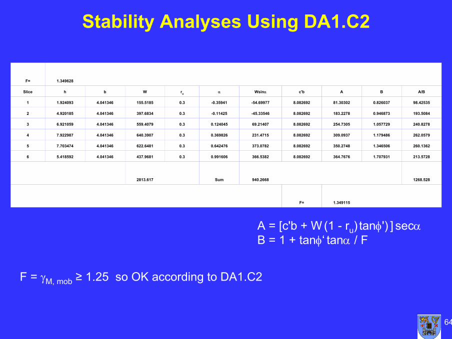
Stability Analyses Using DA1.C2
F = γM, mob ≥ 1.25 so OK according to DA1.C2
1.349115F=
1268.528940.2668Sum2813.617
213.57281.707931364.76768.082692366.53820.9916060.3437.96814.0413465.4185926
260.13621.346506350.27488.082692373.07820.6424760.3622.64814.0413467.7034745
262.05791.179486309.09378.082692231.47150.3698260.3640.39074.0413467.9229874
240.82781.057729254.73058.08269269.214070.1240450.3559.40794.0413466.9210593
193.50840.946873183.22788.082692-45.33546-0.114250.3397.68344.0413464.9201852
98.425350.82603781.303028.082692-54.69977-0.359410.3155.51854.0413461.9240931
A/BBAc'bWsinααruWbhSlice
1.349628F=
A = [c'b + W (1 - ru) tanφ') ] secαB = 1 + tanφ‘ tanα / F
65
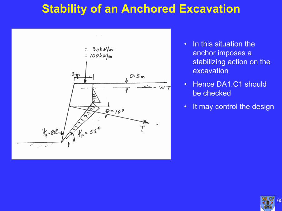
Stability of an Anchored Excavation
• In this situation the anchor imposes a stabilizing action on the excavation
• Hence DA1.C1 should be checked
• It may control the design
66
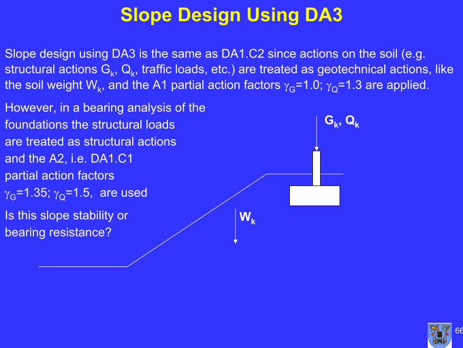
Slope Design Using DA3
Slope design using DA3 is the same as DA1.C2 since actions on the soil (e.g. structural actions Gk, Qk, traffic loads, etc.) are treated as geotechnical actions, likethe soil weight Wk, and the A1 partial action factors γG=1.0; γQ=1.3 are applied.
However, in a bearing analysis of thefoundations the structural loads are treated as structural actions and the A2, i.e. DA1.C1partial action factorsγG=1.35; γQ=1.5, are used
Is this slope stability orbearing resistance?
Gk, Qk
Wk
67
Design of Embankments
• Section 12: Embankments of EN 1997 provides the principles and requirements for the design of embankments for small dams and for infrastructure projects, such as road embankments
– No definition is given for the word “small” but Frank et al. state that it may be appropriate to assume “small dams” include dams (and embankments for infrastructure) up to a height of approximately 10m
• A long list of possible limit states, both GEO and HYD types, that should be checked is provided including:
– Loss of overall stability– Failure in the embankment slope or crest– Failure by internal erosion– Failure by surface erosion or scour– Excessive deformation– Deformations caused by hydraulic actions
• Limit states involving adjacent structures, roads and services are included in the list
68
Particular Aspects Regarding Embankment Design
• Since embankments are constructed by placing fill and sometimes involve ground improvement, the provisions in Section 5 should be applied
• For embankments on ground with low strength and high compressibility, EN 1997-1 states that the construction process shall be specified, i.e. in Geotechnical Design Report, to ensure that the bearing resistance is not exceeded or excessive movements do not occur during construction
• Since the behaviour of embankments on soft ground during construction is usually monitored to ensure failure does not occur, it is often appropriate to use the Observational Method for design
• The importance of both supervision and monitoring in the case of embankments is demonstrated by the fact that there is a separate sub-section on the supervision of the construction of embankments and the monitoring of embankments during and after construction in Section 12
• The only other section of Eurocode 7 that has provisions for both supervision and monitoring is the section on ground anchorages
69
Conclusions
• Sections 11 and 12 set out the provisions for designing against overall stability and for the design of embankments
• The focus is on the relevant limit states to be checked
• No calculation models are provided
• When using method of slices for slope stability, some simplified methods not acceptable
• The relevance and importance of other sections of EN 1997-1 is demonstrated, for example:– The section on Fill and Ground Improvement– The sub-section on the Observational Method– The sub-section on the Geotechnical Design Report– The section on Supervision and Monitoring

70
Discussion
Any questions

71
Tomorrow
- Special Features of Soil- Geotechnical Design
Triangle- Associated CEN
Standards- Implementation and Future Development- Tutorial Examples