Embed Size (px)
Citation preview
Page 1
Corp. 0903−L1
TSA6, 7.5, 10, 12.5, 15 & 20 ton
Revised: March 2011
TSA SERIES UNITS
The TSA units are designed for light commercial applica-tions, with a remotely located blower−coil unit or a furnacewith an add−on evaporator coil. Capacities for the seriesare 6, 7−1/2, 10, 12.5, 15 and 20 tons (21, 26, 35, 44, 53,and 70 kW). All TS units use single speed scroll compres-sors. The 10 (120S4D), 12.5, 15 and 20 ton units each havetwo single−speed scroll compressors. TS units match withthe TA blower−coil units. All TS units are three−phase anduse HFC−410A refrigerant.
This manual covers TSA072S4S, TSA090S4S,TSA120S4S, TSA120S4D, TSA150S4D, TSA180S4Dand TSA240S4D units. It is divided into sections which dis-cuss the major components, refrigerant system, chargingprocedure, maintenance and operation sequence.
Information in this manual is intended for qualified servicetechnicians only. All specifications are subject to change.Procedures in this manual are presented as a recommen-dation only and do not supersede or replace local or statecodes.
WARNING
Electric shock hazard. Can cause injuryor death. Before attempting to performany service or maintenance, turn theelectrical power to unit OFF at discon-nect sw itch(es). Unit may have multiplepower supplies.
WARNINGRefrigerant can be harmful if it is inhaled. Refrigerantmust be used and recovered responsibly.Failure to follow this warning may result in person-al injury or death.
ALL major components (indoor blower/coil) mustbe matched to Lennox recommendations forcompressor to be covered under warranty. Refer toEngineering Handbook for approved systemmatchups.
IMPORTANT
Improper installation, adjustment, alteration,service or maintenance can cause propertydamage, personal injury or loss of life. Installationand service must be performed by a licensedprofessional installer or service agency.
WARNING
TABLE of CONTENTS
Specifications / Electrical Page 2. . . . . . . . .
Parts Arrangement Page 6. . . . . . . . . . . . . . .
I UNIT COMPONENTS Page 10. . . . . . . . . . .
II REFRIGERANT SYSTEM Page 13. . . . . .
III START UP Page 15. . . . . . . . . . . . . . . . . .
IV CHARGING Page 15. . . . . . . . . . . . . . . . . .
V MAINTENANCE Page 21. . . . . . . . . . . . . . .
VI WIRING & OPERATION SEQUENCEPage 22. . . . . . . . . . . . . . . . . . . . . . . . . . . . . . . .
Service Literature
Page 2
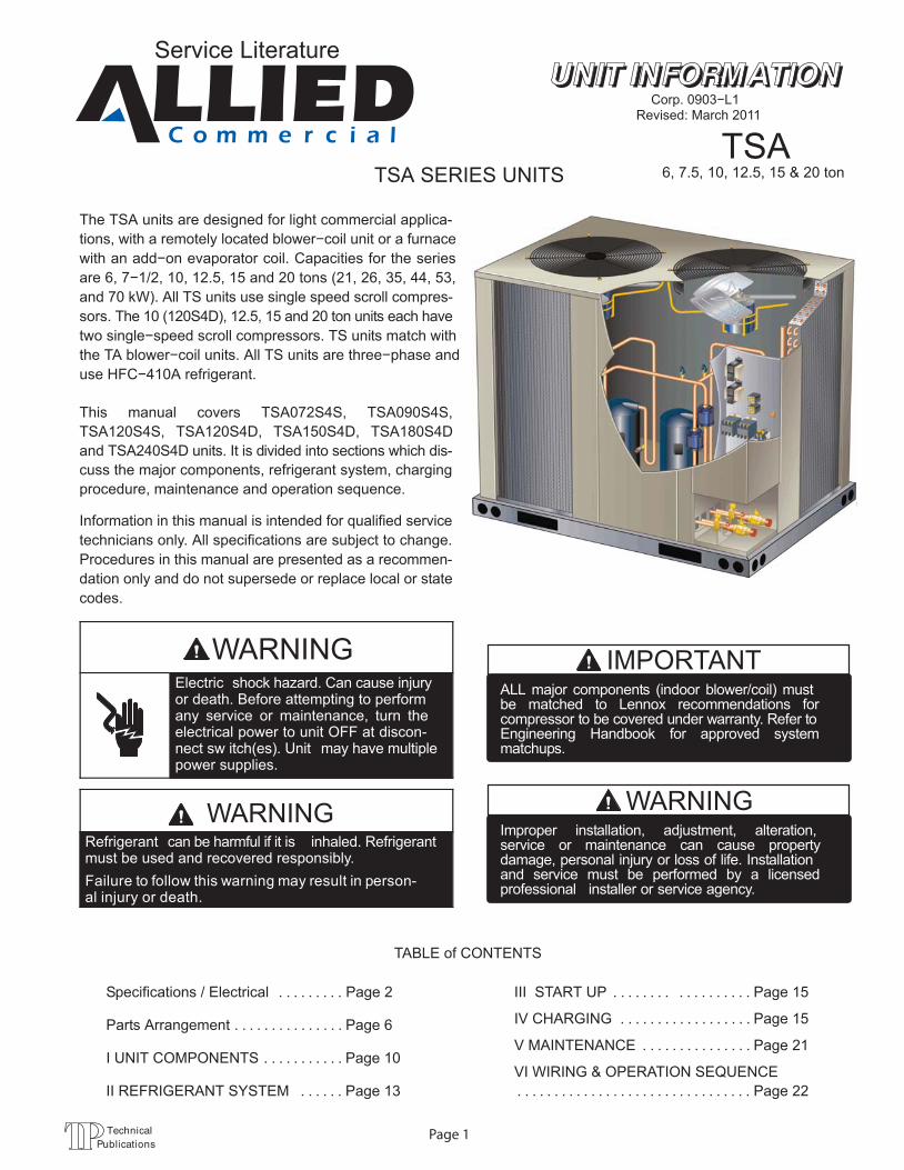
SPECIFICATIONS 6 − 7.5 TON
GeneralData
Model No. TSA072S4S TSA090S4S
Nominal Size − Tons 6 7.5
Connections(sweat)
Liquid line − in. (o.d) (1) 5/8 (1) 5/8
Suction line − in. (o.d) (1) 1−1/8 (1) 1−1/8
Refrigerant R−410A holding charge
CondenserCoil
Net face area − sq. ft. Outer coil 29.3 29.3
Inner coil − − − 28.4
Tube diameter − in. & no. ofrows
3/8 − 1 3/8 − 2
Fins per inch 20 20
CondenserFan(s)
Diameter − in. & no. of blades (1) 24 − 3 (1) 24 − 4
Motor hp (1) 1/3 (1) 1/2
Total air volume − cfm 5100 5600
Rpm 1075 1075
Watts 430 580
Shipping Data lbs. − 1 package 313 367
ELECTRICAL DATA
Line voltage data − 60 hz − 3 phase 208/230V 460V 575V 208/230V 460V 575V
1 Maximum Overcurrent Protection (amps) 45 20 15 50 25 20
2 Minimum circuit ampacity 27 14 11 35 17 13
Compressor No. of Compressors 1 1 1 1 1 1
Rated load amps 19 9.7 7.4 25 12.2 9
Locked rotor amps 123 62 50 164 100 78
CondenserFan�Motor(1 phase)
No. of motors 1 1 1 1 1 1
Full load amps 2.4 1.3 1 3 1.5 1.2
Locked rotor amps 4.7 2.4 1.9 6 3 2.9
NOTE − Extremes of operating range are plus and minus 10% of line voltage.1 HACR type circuit breaker or fuse.2 Refer to National or Canadian Electrical Code manual to determine wire, fuse and disconnect size requirements.
Page 3
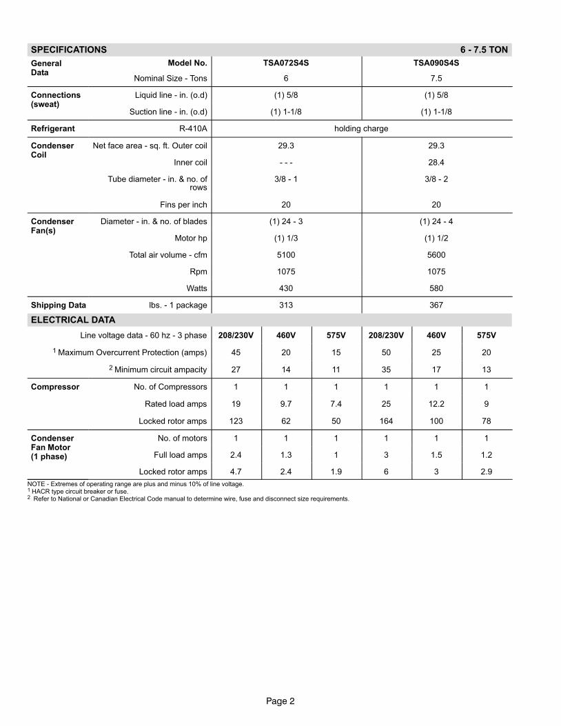
SPECIFICATIONS 10 TON
GeneralData
Model No. TSA120S4S TSA120S4D
Nominal Size − Tons 10 10
Connections(sweat)
Liquid line − in. (o.d) (1) 5/8 (2) 5/8
Suction line − in. (o.d) (1) 1−3/8 (2) 1−1/8
Refrigerant R−410A holding charge
CondenserCoil
Net face area − sq. ft. Outer coil 29.3 29.3
Inner coil 28.4 28.4
Tube diameter − in. & no. of rows 3/8 − 2 3/8 − 2
Fins per inch 20 20
CondenserFan(s)
Diameter − in. & no. of blades (2) 24 − 3 (2) 24 − 3
Motor hp (2) 1/3 (2) 1/3
Total air volume − cfm 8300 8300
Rpm 1075 1075
Watts 830 830
Shipping Data lbs. − 1 package 427 505
ELECTRICAL DATA
Line voltage data − 60 hz − 3 phase 208/230V 460V 575V 208/230V 460V 575V
1 Maximum Overcurrent Protection (amps) 70 40 25 50 25 20
2 Minimum circuit ampacity 43 24 18 41 21 15
Compressor No. of Compressors 1 1 1 2 2 2
Rated load amps (total) 30.1 16.7 12.2 18 (32) 7.8 (15.6) 5.7 (11.4)
Locked rotor amps (total) 225 114 80 110 (220) 52 (104) 38.9 (77.8)
CondenserFan�Motor(1 phase)
No. of motors 2 2 2 2 2 2
Full load amps (total) 2.4 (4.8) 1.3 (2.6) 1 (2) 2.4 (4.8) 1.3 (2.6) 1 (2)
Locked rotor amps (total) 4.7 (9.4) 2.4 (4.8) 1.9 (3.8) 4.7 (9.4) 2.4 (4.8) 1.9 (3.8)
NOTE − Extremes of operating range are plus and minus 10% of line voltage.1 HACR type circuit breaker or fuse.2 Refer to National or Canadian Electrical Code manual to determine wire, fuse and disconnect size requirements.
Page 4
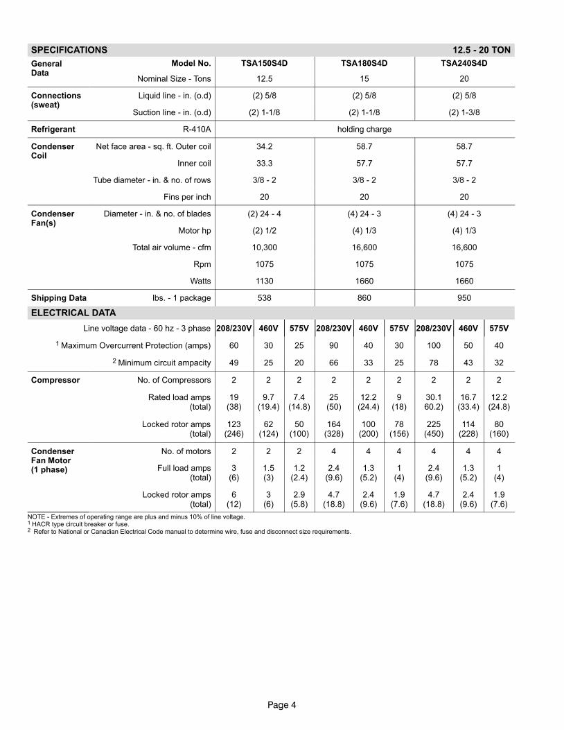
SPECIFICATIONS 12.5 − 20 TON
GeneralData
Model No. TSA150S4D TSA180S4D TSA240S4D
Nominal Size − Tons 12.5 15 20
Connections(sweat)
Liquid line − in. (o.d) (2) 5/8 (2) 5/8 (2) 5/8
Suction line − in. (o.d) (2) 1−1/8 (2) 1−1/8 (2) 1−3/8
Refrigerant R−410A holding charge
CondenserCoil
Net face area − sq. ft. Outer coil 34.2 58.7 58.7
Inner coil 33.3 57.7 57.7
Tube diameter − in. & no. of rows 3/8 − 2 3/8 − 2 3/8 − 2
Fins per inch 20 20 20
CondenserFan(s)
Diameter − in. & no. of blades (2) 24 − 4 (4) 24 − 3 (4) 24 − 3
Motor hp (2) 1/2 (4) 1/3 (4) 1/3
Total air volume − cfm 10,300 16,600 16,600
Rpm 1075 1075 1075
Watts 1130 1660 1660
Shipping Data lbs. − 1 package 538 860 950
ELECTRICAL DATA
Line voltage data − 60 hz − 3 phase 208/230V 460V 575V 208/230V 460V 575V 208/230V 460V 575V
1 Maximum Overcurrent Protection (amps) 60 30 25 90 40 30 100 50 40
2 Minimum circuit ampacity 49 25 20 66 33 25 78 43 32
Compressor No. of Compressors 2 2 2 2 2 2 2 2 2
Rated load amps(total)
19(38)
9.7(19.4)
7.4(14.8)
25(50)
12.2(24.4)
9(18)
30.160.2)
16.7(33.4)
12.2(24.8)
Locked rotor amps(total)
123(246)
62(124)
50(100)
164(328)
100(200)
78(156)
225(450)
114(228)
80(160)
CondenserFan�Motor(1 phase)
No. of motors 2 2 2 4 4 4 4 4 4
Full load amps(total)
3(6)
1.5(3)
1.2(2.4)
2.4(9.6)
1.3(5.2)
1(4)
2.4(9.6)
1.3(5.2)
1(4)
Locked rotor amps(total)
6(12)
3(6)
2.9(5.8)
4.7(18.8)
2.4(9.6)
1.9(7.6)
4.7(18.8)
2.4(9.6)
1.9(7.6)
NOTE − Extremes of operating range are plus and minus 10% of line voltage.1 HACR type circuit breaker or fuse.2 Refer to National or Canadian Electrical Code manual to determine wire, fuse and disconnect size requirements.
Page 5
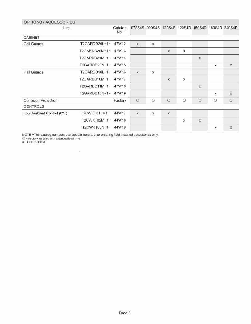
OPTIONS / ACCESSORIES golataCmetI
No.072S4S 090S4S 120S4S 120S4D 150S4D 180S4D 240S4D
CABINET
Coil Guards T2GARDD20L−1− 47W12 x x
T2GARDD20M−1− 47W13 x x
T2GARDD21M−1− 47W14 x
T2GARDD20N−1− 47W15 x x
Hail Guards T2GARDD10L−1− 47W16 x x
T2GARDD10M−1− 47W17 x x
T2GARDD11M−1− 47W18 x
T2GARDD10N−1− 47W19 x x
Corrosion Protection FactoryCONTROLS
Low Ambient Control (0ºF) T2CWKT01LM1− 44W17 x x x
T2CWKT02M−1− 44W18 x x
T2CWKT03N−1− 44W19 x x
NOTE − The catalog numbers that appear here are for ordering field installed accessories only. − Factory Installed with extended lead time
.
X − Field Installed
Page 6
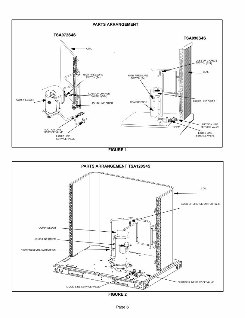
PARTS ARRANGEMENT
HIGH PRESSURESWITCH (S4)
LIQUID LINE DRIER
SUCTION LINESERVICE VALVE
LIQUID LINESERVICE VALVE
LOSS OF CHARGESWITCH (S24)
COIL
COMPRESSOR
COIL
LOSS OF CHARGESWITCH (S24)
SUCTION LINESERVICE VALVE
LIQUID LINESERVICE VALVE
LIQUID LINE DRIERCOMPRESSOR
HIGH PRESSURESWITCH (S4)
TSA090S4STSA072S4S
FIGURE 1
COMPRESSOR
LIQUID LINE SERVICE VALVE
SUCTION LINE SERVICE VALVE
LIQUID LINE DRIER
HIGH PRESSURE SWITCH (S4)
LOSS OF CHARGE SWITCH (S24)
COIL
FIGURE 2
PARTS ARRANGEMENT TSA120S4S
Page 7
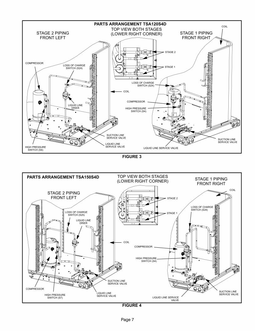
FIGURE 3
STAGE 2 PIPINGFRONT LEFT
STAGE 1 PIPINGFRONT RIGHT
COMPRESSOR
LIQUID LINESERVICE VALVE
SUCTION LINESERVICE VALVE
LIQUID LINEDRIER
HIGH PRESSURESWITCH (S4)
LOSS OF CHARGESWITCH (S24)
COMPRESSOR
LOSS OF CHARGESWITCH (S24)
HIGH PRESSURESWITCH (S4)
SUCTION LINESERVICE VALVE
LIQUID LINE SERVICE VALVE
COIL
COILPARTS ARRANGEMENT TSA120S4D
TOP VIEW BOTH STAGES(LOWER RIGHT CORNER)
STAGE 1
STAGE 2
PARTS ARRANGEMENT TSA150S4D
FIGURE 4
STAGE 1 PIPINGFRONT RIGHT
TOP VIEW BOTH STAGES(LOWER RIGHT CORNER)
COMPRESSOR
LIQUID LINESERVICE VALVE
SUCTION LINESERVICE VALVE
HIGH PRESSURESWITCH (S7)
COMPRESSOR
LOSS OF CHARGESWITCH (S24)
HIGH PRESSURESWITCH (S4)
SUCTION LINESERVICE VALVE
LIQUID LINE SERVICEVALVE
COIL
STAGE 2 PIPINGFRONT LEFT
LOSS OF CHARGESWITCH (S25)
LIQUID LINEDRIER
COIL
STAGE 1
STAGE 2
Page 8
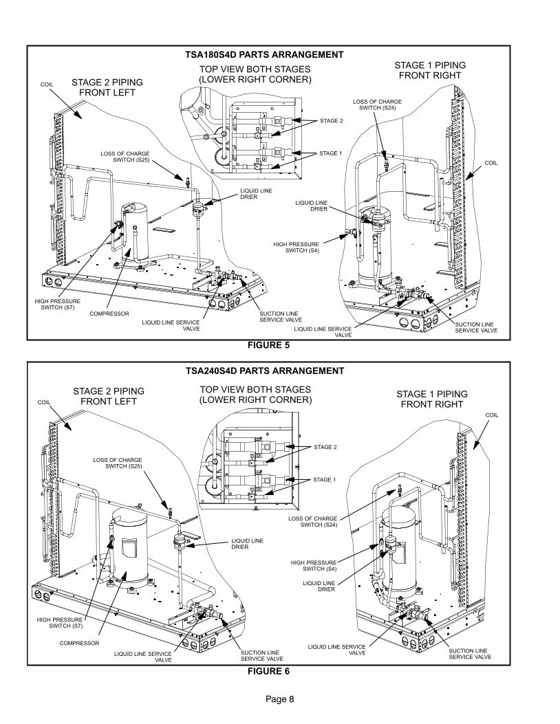
TSA180S4D PARTS ARRANGEMENT
FIGURE 5
STAGE 1 PIPINGFRONT RIGHT
TOP VIEW BOTH STAGES(LOWER RIGHT CORNER)STAGE 2 PIPING
FRONT LEFT
COMPRESSOR
LIQUID LINE SERVICEVALVE
SUCTION LINESERVICE VALVE
HIGH PRESSURESWITCH (S7)
COIL
LOSS OF CHARGESWITCH (S25)
LIQUID LINEDRIER
COIL
SUCTION LINESERVICE VALVELIQUID LINE SERVICE
VALVE
HIGH PRESSURESWITCH (S4)
LOSS OF CHARGESWITCH (S24)
LIQUID LINEDRIER
STAGE 1
STAGE 2
TSA240S4D PARTS ARRANGEMENT
FIGURE 6
STAGE 1 PIPINGFRONT RIGHT
TOP VIEW BOTH STAGES(LOWER RIGHT CORNER)
STAGE 2 PIPINGFRONT LEFT
COMPRESSOR
LIQUID LINE SERVICEVALVE
SUCTION LINESERVICE VALVE
HIGH PRESSURESWITCH (S7)
COIL
LOSS OF CHARGESWITCH (S25)
LIQUID LINEDRIER
LIQUID LINEDRIER
SUCTION LINESERVICE VALVE
LIQUID LINE SERVICEVALVE
HIGH PRESSURESWITCH (S4)
LOSS OF CHARGESWITCH (S24)
COIL
STAGE 1
STAGE 2
Page 9
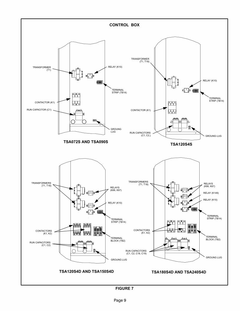
CONTROL BOX
FIGURE 7
CONTACTOR (K1)
RUN CAPACITOR (C1)
TSA072S AND TSA090S
TSA120S4D AND TSA150S4D
TSA120S4S
TSA180S4D AND TSA240S4D
GROUNGLUG
TERMINALSTRIP (TB14)
RELAY (K10)TRANSFORMER(T1)
TRANSFORMER(T1, T18)
CONTACTOR (K1)
RUN CAPACITORS(C1, C2,) GROUNG LUG
TERMINALSTRIP (TB14)
RELAY (K10)
TRANSFORMERS(T1, T18)
CONTACTORS(K1, K2)
RUN CAPACITORS(C1, C2)
GROUNG LUG
TERMINALSTRIP (TB14)
TERMINALBLOCK (TB2)
RELAY (K10)
RELAYS(K66, K67)
GROUNG LUG
TERMINALBLOCK (TB2)
TERMINALSTRIP (TB14)
TRANSFORMERS(T1, T18)
CONTACTORS(K1, K2)
RUN CAPACITORS(C1, C2, C18, C19)
RELAY (K149)
RELAYS(K66, K67)
RELAY (K10)
Page 10
I−UNIT COMPONENTS
The TSA parts arrangements are shown in figures 1
through 5 and control boxes in figure 7.
ELECTROSTATIC DISCHARGE (ESD)
Precautions and Procedures
CAUTIONElectrostatic discharge can affect electronic com-ponents. Take precautions during unit installationand service to protect the unit’s electronic con-trols. Precautions will help to avoid control expo-sure to electrostatic discharge by putting the unit,the control and the technician at the same electro-static potential. Neutralize electrostatic charge bytouching hand and all tools on an unpainted unitsurface before performing any service procedure.
A−CONTROL BOX COMPONENTS
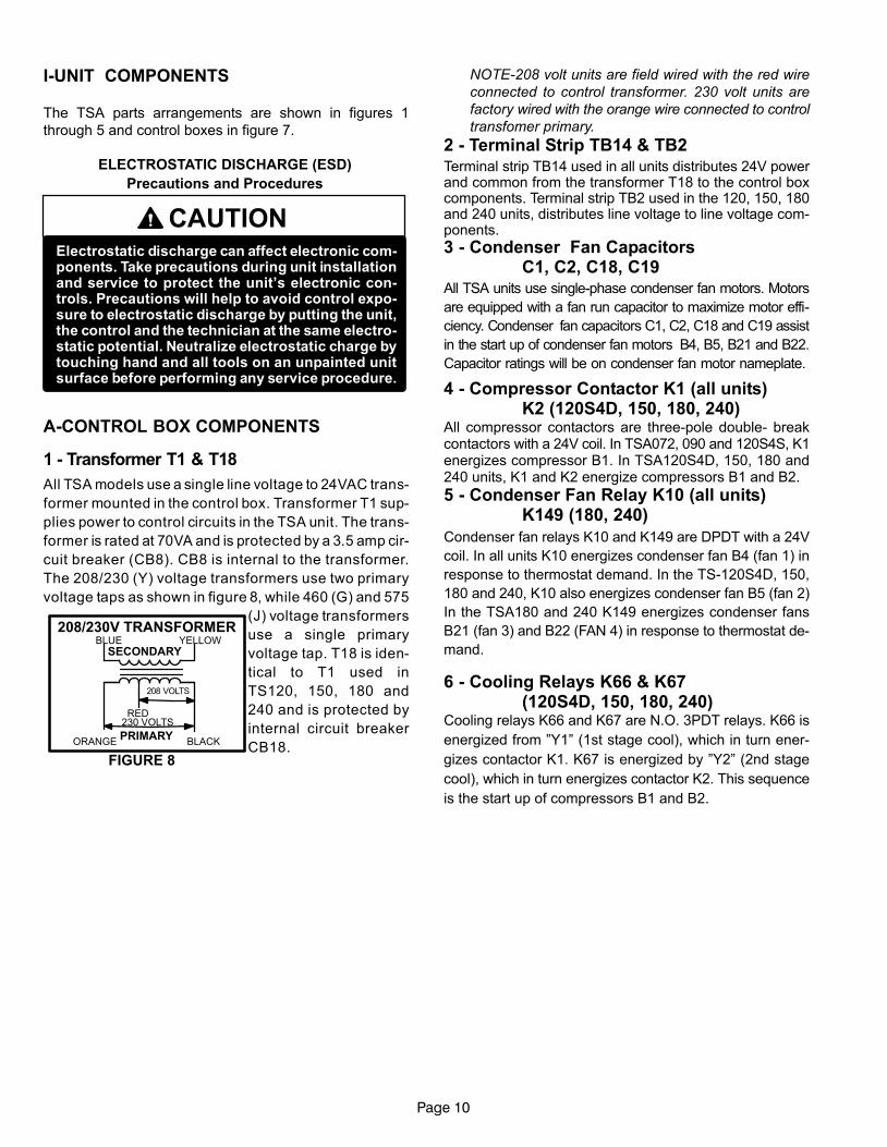
1 − Transformer T1 & T18
All TSA models use a single line voltage to 24VAC trans-
former mounted in the control box. Transformer T1 sup-
plies power to control circuits in the TSA unit. The trans-
former is rated at 70VA and is protected by a 3.5 amp cir-
cuit breaker (CB8). CB8 is internal to the transformer.
The 208/230 (Y) voltage transformers use two primary
voltage taps as shown in figure 8, while 460 (G) and 575
(J) voltage transformers
use a single primary
voltage tap. T18 is iden-
tical to T1 used in
TS120, 150, 180 and
240 and is protected by
internal circuit breaker
CB18.
NOTE−208 volt units are field wired with the red wire
connected to control transformer. 230 volt units are
factory wired with the orange wire connected to control
transfomer primary.
2 − Terminal Strip TB14 & TB2Terminal strip TB14 used in all units distributes 24V powerand common from the transformer T18 to the control boxcomponents. Terminal strip TB2 used in the 120, 150, 180and 240 units, distributes line voltage to line voltage com-ponents.
3 − Condenser Fan CapacitorsC1, C2, C18, C19
All TSA units use single−phase condenser fan motors. Motors
are equipped with a fan run capacitor to maximize motor effi-
ciency. Condenser fan capacitors C1, C2, C18 and C19 assist
in the start up of condenser fan motors B4, B5, B21 and B22.
Capacitor ratings will be on condenser fan motor nameplate.
4 − Compressor Contactor K1 (all units) K2 (120S4D, 150, 180, 240)
All compressor contactors are three−pole double− breakcontactors with a 24V coil. In TSA072, 090 and 120S4S, K1energizes compressor B1. In TSA120S4D, 150, 180 and240 units, K1 and K2 energize compressors B1 and B2.
5 − Condenser Fan Relay K10 (all units) K149 (180, 240)
Condenser fan relays K10 and K149 are DPDT with a 24V
coil. In all units K10 energizes condenser fan B4 (fan 1) in
response to thermostat demand. In the TS−120S4D, 150,
180 and 240, K10 also energizes condenser fan B5 (fan 2)
In the TSA180 and 240 K149 energizes condenser fans
B21 (fan 3) and B22 (FAN 4) in response to thermostat de-
mand.
6 − Cooling Relays K66 & K67(120S4D, 150, 180, 240)
Cooling relays K66 and K67 are N.O. 3PDT relays. K66 is
energized from "Y1" (1st stage cool), which in turn ener-
gizes contactor K1. K67 is energized by "Y2" (2nd stage
cool), which in turn energizes contactor K2. This sequence
is the start up of compressors B1 and B2.
FIGURE 8
BLUE YELLOW
ORANGE
RED
BLACK
230 VOLTS
208 VOLTS
PRIMARY
SECONDARY
208/230V TRANSFORMER
Page 11
B−COOLING COMPONENTS
WARNINGRefrigerant can be harmful if it is inhaled. Refrigerantmust be used and recovered responsibly.
Failure to follow this warning may result in person-al injury or death.
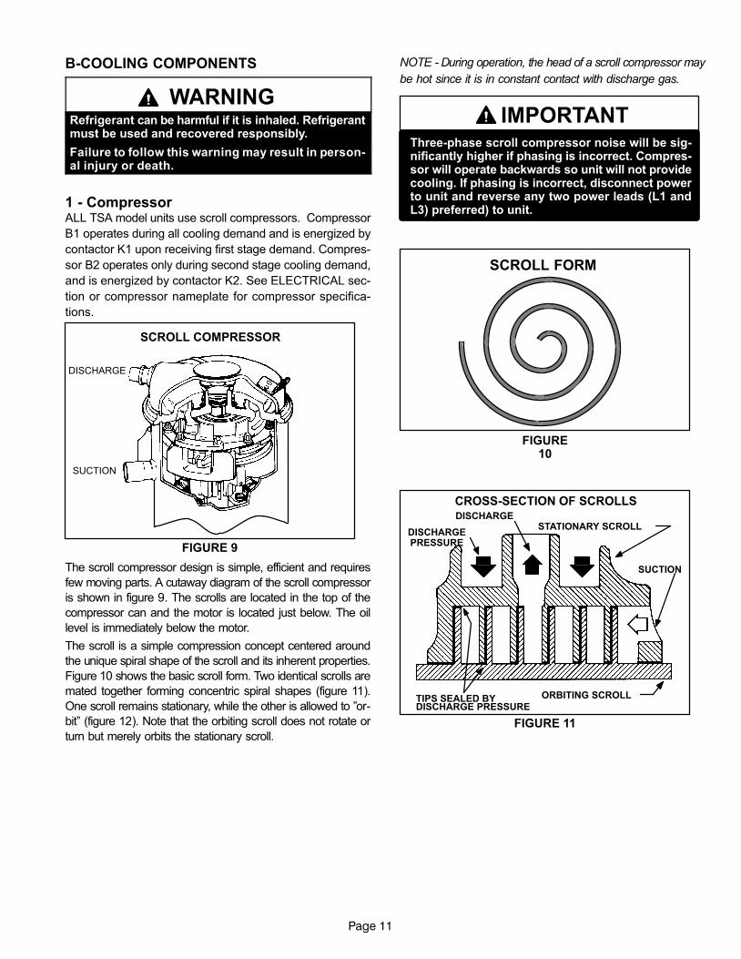
1 − CompressorALL TSA model units use scroll compressors. Compressor
B1 operates during all cooling demand and is energized by
contactor K1 upon receiving first stage demand. Compres-
sor B2 operates only during second stage cooling demand,
and is energized by contactor K2. See ELECTRICAL sec-
tion or compressor nameplate for compressor specifica-
tions.
FIGURE 9
SCROLL COMPRESSOR
DISCHARGE
SUCTION
The scroll compressor design is simple, efficient and requires
few moving parts. A cutaway diagram of the scroll compressor
is shown in figure 9. The scrolls are located in the top of the
compressor can and the motor is located just below. The oil
level is immediately below the motor.
The scroll is a simple compression concept centered around
the unique spiral shape of the scroll and its inherent properties.
Figure 10 shows the basic scroll form. Two identical scrolls are
mated together forming concentric spiral shapes (figure 11).
One scroll remains stationary, while the other is allowed to "or-
bit" (figure 12). Note that the orbiting scroll does not rotate or
turn but merely orbits the stationary scroll.
NOTE − During operation, the head of a scroll compressor may
be hot since it is in constant contact with discharge gas.
IMPORTANTThree−phase scroll compressor noise will be sig-nificantly higher if phasing is incorrect. Compres-sor will operate backwards so unit will not providecooling. If phasing is incorrect, disconnect powerto unit and reverse any two power leads (L1 andL3) preferred) to unit.
FIGURE10
SCROLL FORM
FIGURE 11
STATIONARY SCROLL
ORBITING SCROLL
DISCHARGE
SUCTION
CROSS−SECTION OF SCROLLS
TIPS SEALED BYDISCHARGE PRESSURE
DISCHARGEPRESSURE
Page 12
1 2
3 4
SUCTIONPOCKET
SUCTION
ORBITING SCROLL
STATIONARY SCROLL
SUCTIONSUCTION
DISCHARGE POCKET
SUCTION INTERMEDIATE PRESSUREGAS
CRECENT SHAPEDGAS POCKET
HIGH PRESSURE GAS
FLANKS SEALEDBY CENTRIFUGAL
FORCE
MOVEMENT OF ORBIT
FIGURE 12
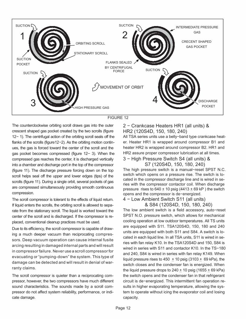
The counterclockwise orbiting scroll draws gas into the outercrescent shaped gas pocket created by the two scrolls (figure12− 1). The centrifugal action of the orbiting scroll seals off theflanks of the scrolls (figure12−2). As the orbiting motion contin-ues, the gas is forced toward the center of the scroll and thegas pocket becomes compressed (figure 12− 3). When thecompressed gas reaches the center, it is discharged verticallyinto a chamber and discharge port in the top of the compressor(figure 11). The discharge pressure forcing down on the topscroll helps seal off the upper and lower edges (tips) of thescrolls (figure 11). During a single orbit, several pockets of gasare compressed simultaneously providing smooth continuouscompression.The scroll compressor is tolerant to the effects of liquid return.If liquid enters the scrolls, the orbiting scroll is allowed to sepa-rate from the stationary scroll. The liquid is worked toward thecenter of the scroll and is discharged. If the compressor is re-placed, conventional cleanup practices must be used.Due to its efficiency, the scroll compressor is capable of draw-ing a much deeper vacuum than reciprocating compres-sors. Deep vacuum operation can cause internal fusitearcing resulting in damaged internal parts and will resultin compressor failure. Never use a scroll compressor for
damage can be detected and will result in denial of war-ranty claims.
The scroll compressor is quieter than a reciprocating com-pressor, however, the two compressors have much differentsound characteristics. The sounds made by a scroll com-pressor do not affect system reliability, performance, or indi-cate damage.
2 − Crankcase Heaters HR1 (all units) & HR2 (120S4D, 150, 180, 240)All TSA series units use a belly−band type crankcase heat-er. Heater HR1 is wrapped around compressor B1 andheater HR2 is wrapped around compressor B2. HR1 andHR2 assure proper compressor lubrication at all times.3 − High Pressure Switch S4 (all units) &
S7 (120S4D, 150, 180, 240)The high pressure switch is a manual−reset SPST N.C.switch which opens on a pressure rise. The switch is lo-cated in the compressor discharge line and is wired in se-ries with the compressor contactor coil. When dischargepressure rises to 640 + 10 psig (4413 + 69 kP ) the switchopens and the compressor is de−energized.4 − Low Ambient Switch S11 (all units)
& S84 (120S4D, 150, 180, 240)The low ambient switch is a field accessory, auto−resetSPST N.O. pressure switch, which allows for mechanicalcooling operation at low outdoor temperatures. All TS unitsare equipped with S11. TSA120S4D, 150, 180 and 240units are equipped with both S11 and S84. A switch is lo-cated in each liquid line. In all TSA units, S11 is wired in se-ries with fan relay K10. In the TSA120S4D and 150, S84 iswired in series with S11 and contactor K10. In the TS−180and 240, S84 is wired in series with fan relay K149. Whenliquid pressure rises to 450 + 10 psig (3103 + 69 kPa), theswitch closes and the condenser fan is energized. Whenthe liquid pressure drops to 240 + 10 psig (1655 + 69 kPa)the switch opens and the condenser fan in that refrigerantcircuit is de−energized. This intermittent fan operation re-sults in higher evaporating temperature, allowing the sys-tem to operate without icing the evaporator coil and losingcapacity.
Page 13
5 − Filter Drier (all units)All TS model units have a filter drier that is located in the
liquid line of each refrigerant circuit at the exit of each con-
denser coil. The drier removes contaminants and moisture
from the system.
6 − Condenser Fan B4 (all units)B5 (120S4D, 150, 180, 240)B21 & B22 (180, 240)
See page 2 for the specifications on the condenser fans
used in the TS units. All condenser fans have single− phase
motors. The TSA072 and 090 units are equipped with a
single condenser fan. The TSA120 and 150 are equipped
with two fans and the 180 and 240 have four fans. The fan
assembly may be removed for servicing by removing the
fan grill, unplugging the motor then loosening the motor
bracket. The assembly will lift out.
7 − Loss of Charge Switch S24 & S25The loss of charge switch is an auto−reset SPST N.C.
switch which opens on a pressure drop (almost a complete
loss of charge). All TSA units have S24 and the 120S4D
through 240 have S25. The switch is located in the liquid
line and wired in series with compressor contactor and high
pressure switch. S24 is wired in series with first stage cool
and S25 is wired in series with second stage cool. When
pressure drops below 40+ 5 psig (indicating loss of charge
in the system) the switch opens and compressor is de−en-
ergized. The switch automatically resets when refrigerant
is added and pressure in the discharge line rises above 90+
5 psig.
II− REFRIGERANT SYSTEMA−PlumbingField refrigerant piping consists of liquid and suction lines
connecting the condensing unit and the indoor unit. Liquid
and suction service valves are located in a compartment at
the corner of the unit below the control box. Piping can be
routed directly from the service valves or field supplied el-
bows can be added to divert the piping as required
Refer to table 1 for field−fabricated refrigerant line sizes for
runs up to 50 linear feet (15 m).
TABLE 1
TSA Unit Liquid Line Suction Line
072 5/8" (16 mm) 1−1/8" (29 mm)
090 5/8" (16 mm) 1−1/8" (29 mm)
120S4S 5/8" (16 mm) 1−3/8" (35 mm)
120S4D 5/8" (16 mm) 1−1/8" (29 mm)
150 5/8" (16 mm) 1−1/8" (29 mm)
180 5/8" (16 mm) 1−1/8" (29 mm)
240 5/8" (16 mm) 1−3/8" (35 mm)
Refrigerant Line Limitations
You may install the unit in applications that have line set
lengths of up to 50 linear feet (15 m) with refrigerant line
sizes as outlined in table 1 (excluding equivalent length of
fittings). Size refrigerant lines greater than 50 linear feet
(15m or greater) according to the Lennox Refrigerant Pip-
ing Design and Fabrication Guidelines (Corp. 9351−L9) or
latest version.
B−Service Valves
OPERATING SERVICE VALVES
The liquid and suction line service valves are typically used
for removing refrigerant, flushing, leak testing, evacuating,
checking charge and charging.
IMPORTANTOnly use Allen wrenches of sufficient hardness(50Rc − Rockwell Harness Scale minimum). Fullyinsert the wrench into the valve stem recess.
Service valve stems are factory−torqued (from 9ft−lbs for small valves, to 25 ft−lbs for large valves) toprevent refrigerant loss during shipping andhandling. Using an Allen wrench rated at less than50Rc risks rounding or breaking off the wrench, orstripping the valve stem recess.
Each valve is equipped with a service port which has a fac-
tory−installed valve stem.
123
45
678
910
11 12
1/6 TURN
123
4567
8910
11 12
1/12 TURN
FIGURE 13
Cap Tightening Distances
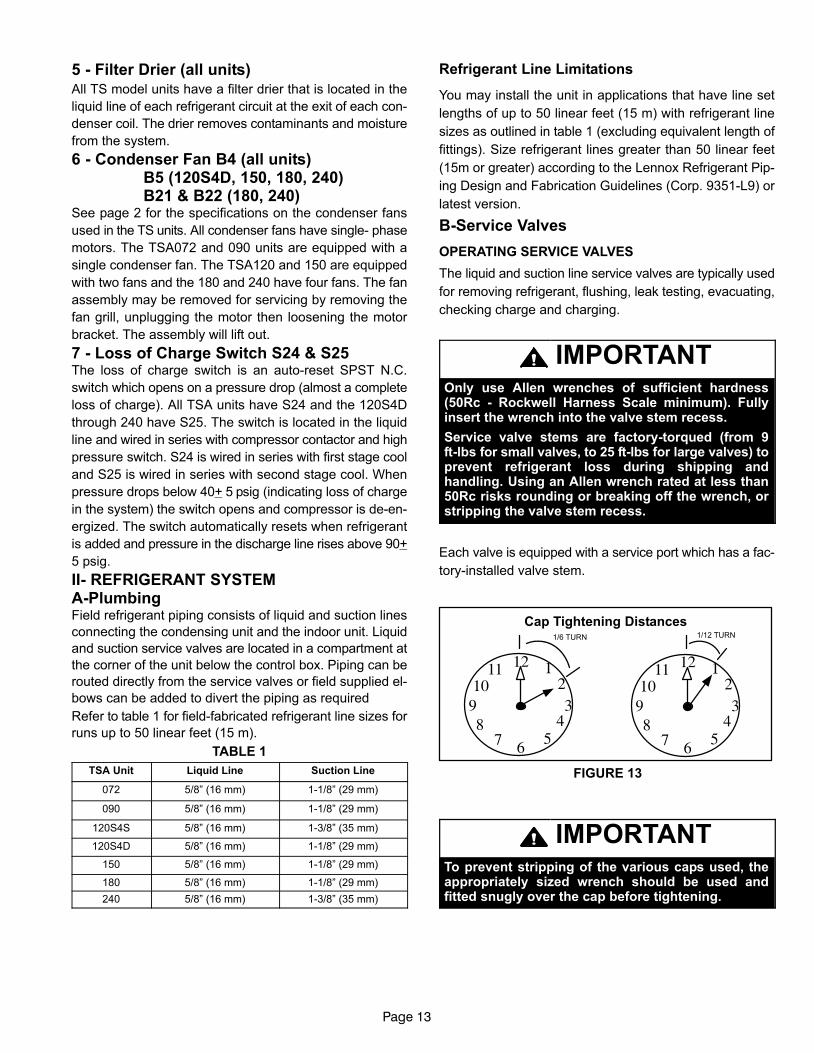
IMPORTANTTo prevent stripping of the various caps used, theappropriately sized wrench should be used andfitted snugly over the cap before tightening.
Page 14
TABLE 2Torque Requirements
Part Recommended Torque
Service valve cap 8 ft.− lb. 11 NM
Sheet metal screws 16 in.− lb. 2 NM
Machine screws #10 28 in.− lb. 3 NM
Compressor bolts 90 in.− lb. 10 NM
Gauge port seal cap 8 ft.− lb. 11 NM
To Access Angle−Type Service Port:
A service port cap protects the service port core from con-
tamination and serves as the primary leak seal.
1.. Remove service port cap with an appropriately sized
wrench.
2.. Connect gauge to the service port.
3.. When testing is completed, replace service port cap and
tighten as follows:
� With Torque Wrench: Finger tighten and then tight-
en per table 2.
� Without Torque Wrench: Finger tighten and use an
appropriately sized wrench to turn an additional
1/6 turn clockwise as illustrated in figure 13.
To Open Liquid Line Service Valve:
1 − Remove stem cap with an adjustable wrench.
2 − Using service wrench and 5/16" hex head extension if
needed (part #49A71) back the stem out counterclock-
wise until the valve stem just touches the retaining ring.
3 − Replace stem cap. Tighten finger tight, then tighten an
additional 1/6 turn. Do not over torque.
To Close Liquid Line Service Valve:
1 − Remove stem cap with an adjustable wrench.
2 − Using service wrench and 5/16" hex head extension if
needed (part #49A71), turn stem clockwise to seat the
valve. Tighten firmly.
3 − Replace stem cap. Tighten finger tight, then tighten an
additional 1/6 turn. Do not over torque.
3 − Replace stem cap. Tighten finger tight, then tighten an
additional 1/6 turn. Do not over torque.
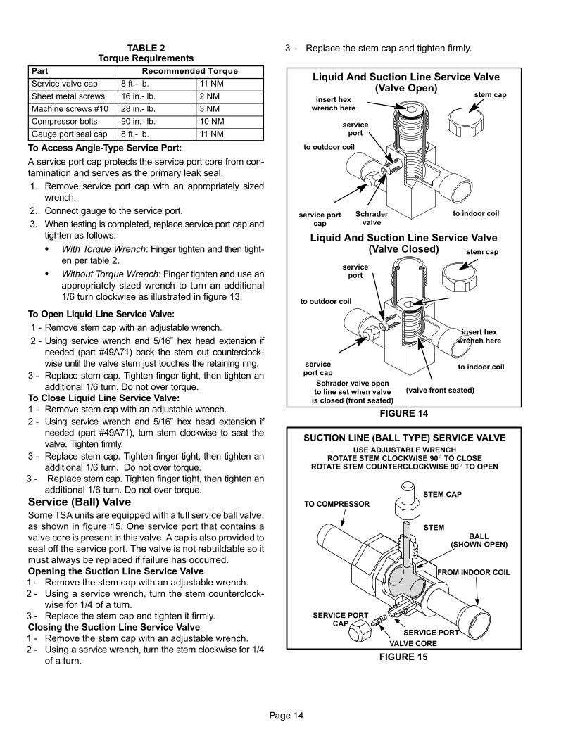
Service (Ball) ValveSome TSA units are equipped with a full service ball valve,
as shown in figure 15. One service port that contains a
valve core is present in this valve. A cap is also provided to
seal off the service port. The valve is not rebuildable so it
must always be replaced if failure has occurred.
Opening the Suction Line Service Valve
1 − Remove the stem cap with an adjustable wrench.
2 − Using a service wrench, turn the stem counterclock-
wise for 1/4 of a turn.
3 − Replace the stem cap and tighten it firmly.
Closing the Suction Line Service Valve
1 − Remove the stem cap with an adjustable wrench.
2 − Using a service wrench, turn the stem clockwise for 1/4
of a turn.
3 − Replace the stem cap and tighten firmly.
FIGURE 14
Liquid And Suction Line Service Valve(Valve Open)
Schradervalve
serviceport
service portcap
insert hexwrench here
to indoor coil
to outdoor coil
stem cap
Schrader valve opento line set when valve
is closed (front seated)
serviceport
serviceport cap
stem cap
insert hexwrench here
Liquid And Suction Line Service Valve(Valve Closed)
(valve front seated)
to outdoor coil
to indoor coil
SUCTION LINE (BALL TYPE) SERVICE VALVE
VALVE CORE
SERVICE PORT
STEM CAP
STEM
USE ADJUSTABLE WRENCHROTATE STEM CLOCKWISE 90� TO CLOSE
ROTATE STEM COUNTERCLOCKWISE 90� TO OPEN
BALL(SHOWN OPEN)
FROM INDOOR COIL
TO COMPRESSOR
SERVICE PORTCAP
FIGURE 15
Page 15
III−START UP
The following is a general procedure and does not apply to
all thermostat control systems. Refer to sequence of op-
eration in this manual for more information.
WARNINGCrankcase heaters must be energized for 24 hoursbefore attempting to start compressors. Set ther-mostat so there is no compressor demand beforeclosing disconnect switch. Attempting to startcompressors during the 24−hour warm −up periodcould result in damage or failed compressors.
1 − Set fan switch to AUTO or ON and move the system
selection switch to COOL. Adjust the thermostat to a
setting far enough below room temperature to bring on
compressors. Compressors will start and cycle on de-
mand from the thermostat (allowing for unit and thermo-
stat time delays).
2 − Each circuit is field charged with HCFC−410A refrigerant.
3 − Refer to Charging section for proper method of check-
ing and charging the system.
IMPORTANTThree-phase scroll compressors must be phasedsequentially to ensure correct compressor rotationand operation. At compressor start-up, a rise indischarge and drop in suction pressures indicateproper compressor phasing and operation. If dis-charge and suctions pressures do not perform nor-mally, follow the steps below to correctly phase inthe unit.
1 − Disconnect power to the unit.
2 − Reverse any two field power leads (L1 and L3 pre-
ferred) to the unit.
3 − Reapply power to the unit.
Discharge and suction pressures should operate at their
normal start-up ranges.
NOTE − Compressor noise level will be significantly higher
when phasing is incorrect and the unit will not provide cool-
ing when compressor is operating backwards. Continued
backward operation will cause the compressor to cycle on
internal protector.
IV− CHARGING
A−Leak Testing
IMPORTANTLeak detector must be capable of sensing HFCrefrigerant.
WARNINGRefrigerant can be harmful if it is inhaled.Refrigerant must be used and recoveredresponsibly.
Failure to follow this warning may result in personalinjury or death.
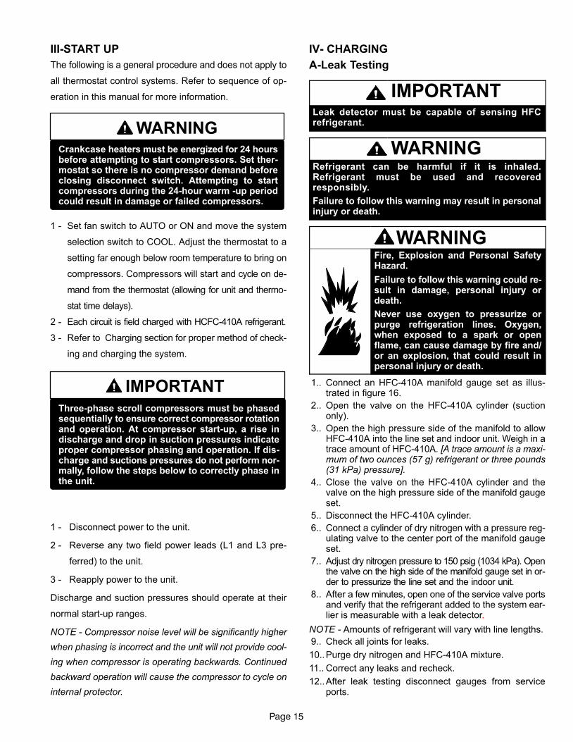
WARNINGFire, Explosion and Personal SafetyHazard.
Failure to follow this warning could re-sult in damage, personal injury ordeath.
Never use oxygen to pressurize orpurge refrigeration lines. Oxygen,when exposed to a spark or openflame, can cause damage by fire and/or an explosion, that could result inpersonal injury or death.
1.. Connect an HFC−410A manifold gauge set as illus-trated in figure 16.
2.. Open the valve on the HFC−410A cylinder (suctiononly).
3.. Open the high pressure side of the manifold to allowHFC−410A into the line set and indoor unit. Weigh in atrace amount of HFC−410A. [A trace amount is a maxi-mum of two ounces (57 g) refrigerant or three pounds(31 kPa) pressure].
4.. Close the valve on the HFC−410A cylinder and thevalve on the high pressure side of the manifold gaugeset.
5.. Disconnect the HFC−410A cylinder.
6.. Connect a cylinder of dry nitrogen with a pressure reg-ulating valve to the center port of the manifold gaugeset.
7.. Adjust dry nitrogen pressure to 150 psig (1034 kPa). Openthe valve on the high side of the manifold gauge set in or-der to pressurize the line set and the indoor unit.
8.. After a few minutes, open one of the service valve portsand verify that the refrigerant added to the system ear-lier is measurable with a leak detector.
NOTE − Amounts of refrigerant will vary with line lengths.
9.. Check all joints for leaks.
10..Purge dry nitrogen and HFC−410A mixture.
11.. Correct any leaks and recheck.
12..After leak testing disconnect gauges from serviceports.
Page 16
TO SUCTION
SERVICE VALVE
HFC−410A
MANIFOLD
GAUGE SET
NITROGEN
OUTDOOR UNIT
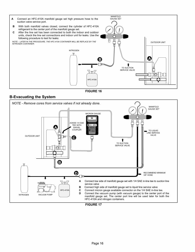
A Connect an HFC−410A manifold gauge set high pressure hose to thesuction valve service port.
B With both manifold valves closed, connect the cylinder of HFC−410Arefrigerant to the center port of the manifold gauge set.
C After the line set has been connected to both the indoor and outdoorunits, check the line set connections and indoor unit for leaks. Use thefollowing procedure to test for leaks:
AB
NOTE − LATER IN THE PROCEDURE, THE HFC−410A CONTAINER WILL BE REPLACE BY THENITROGEN CONTAINER.
FIGURE 16
B−Evacuating the System
OUTDOOR UNIT
TO SUCTION
SERVICE VALVE
TO LIQUID
LINE SERVICE
VALVE
MICRON GAUGE
VACUUM PUMP
A34000 1/4 SAE
TEE WITH
SWIVEL
COUPLER
NITROGEN
50
MANIFOLD
GAUGE SET
HFC−410A
RECOMMEND MINIMUM
3/8" HOSE
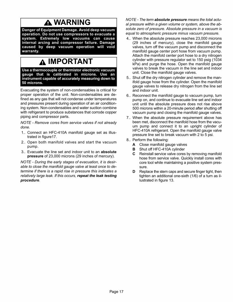
A Connect low side of manifold gauge set with 1/4 SAE in−line tee to suction lineservice valve
B Connect high side of manifold gauge set to liquid line service valve
C Connect micron gauge available connector on the 1/4 SAE in−line tee.
D Connect the vacuum pump (with vacuum gauge) to the center port of themanifold gauge set. The center port line will be used later for both theHFC−410A and nitrogen containers.
A
B
C
D
NOTE − Remove cores from service valves if not already done.
FIGURE 17
Page 17
WARNINGDanger of Equipment Damage. Avoid deep vacuumoperation. Do not use compressors to evacuate asystem. Extremely low vacuums can causeinternal arcing and compressor failure. Damagecaused by deep vacuum operation will voidwarranty.
IMPORTANTUse a thermocouple or thermistor electronic vacuumgauge that is calibrated in microns. Use aninstrument capable of accurately measuring down to50 microns.
Evacuating the system of non−condensables is critical forproper operation of the unit. Non−condensables are de-fined as any gas that will not condense under temperaturesand pressures present during operation of an air condition-ing system. Non−condensables and water suction combinewith refrigerant to produce substances that corrode copperpiping and compressor parts.
NOTE − Remove cores from service valves if not already
done.
1.. Connect an HFC−410A manifold gauge set as illus-trated in figure17.
2.. Open both manifold valves and start the vacuumpump.
3.. Evacuate the line set and indoor unit to an absolutepressure of 23,000 microns (29 inches of mercury).
NOTE − During the early stages of evacuation, it is desir-
able to close the manifold gauge valve at least once to de-
termine if there is a rapid rise in pressure this indicates a
relatively large leak. If this occurs, repeat the leak testing
procedure.
NOTE − The term absolute pressure means the total actu-
al pressure within a given volume or system, above the ab-
solute zero of pressure. Absolute pressure in a vacuum is
equal to atmospheric pressure minus vacuum pressure.
4.. When the absolute pressure reaches 23,000 microns(29 inches of mercury), close the manifold gaugevalves, turn off the vacuum pump and disconnect themanifold gauge center port hose from vacuum pump.Attach the manifold center port hose to a dry nitrogencylinder with pressure regulator set to 150 psig (1034kPa) and purge the hose. Open the manifold gaugevalves to break the vacuum in the line set and indoorunit. Close the manifold gauge valves.
5.. Shut off the dry nitrogen cylinder and remove the man-ifold gauge hose from the cylinder. Open the manifoldgauge valves to release dry nitrogen from the line setand indoor unit.
6.. Reconnect the manifold gauge to vacuum pump, turnpump on, and continue to evacuate line set and indoorunit until the absolute pressure does not rise above500 microns within a 20−minute period after shutting offvacuum pump and closing the manifold gauge valves.
7.. When the absolute pressure requirement above hasbeen met, disconnect the manifold hose from the vacu-um pump and connect it to an upright cylinder ofHFC−410A refrigerant. Open the manifold gauge valvepressure line set to break vacuum with 2 to 5 psi.
8.. Perform the following:
A Close manifold gauge valves
B Shut off HFC−410A cylinder
C Reinstall service valve cores by removing manifoldhose from service valve. Quickly install cores withcore tool while maintaining a positive system pres-sure.
D Replace the stem caps and secure finger tight, thentighten an additional one−sixth (1/6) of a turn as il-lustrated in figure 13.
Page 18
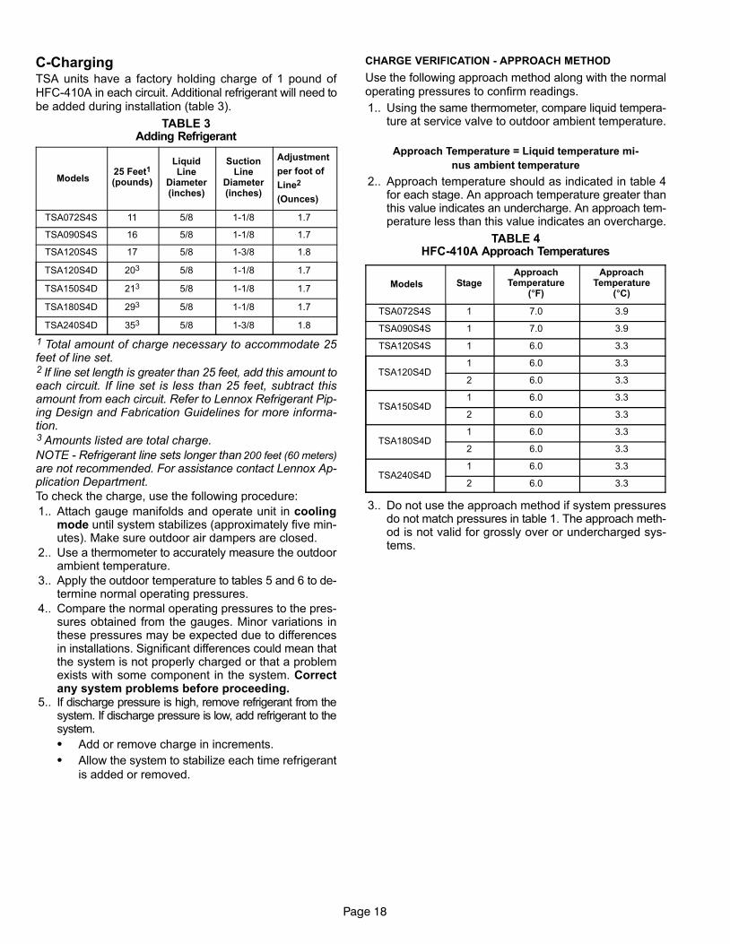
C−ChargingTSA units have a factory holding charge of 1 pound ofHFC−410A in each circuit. Additional refrigerant will need tobe added during installation (table 3).
TABLE 3Adding Refrigerant
Models25 Feet1
(pounds)
LiquidLine
Diameter(inches)
SuctionLine
Diameter(inches)
Adjustment
per foot of
Line2
(Ounces)
TSA072S4S 11 5/8 1−1/8 1.7
TSA090S4S 16 5/8 1−1/8 1.7
TSA120S4S 17 5/8 1−3/8 1.8
TSA120S4D 203 5/8 1−1/8 1.7
TSA150S4D 213 5/8 1−1/8 1.7
TSA180S4D 293 5/8 1−1/8 1.7
TSA240S4D 353 5/8 1−3/8 1.8
1 Total amount of charge necessary to accommodate 25feet of line set.2 If line set length is greater than 25 feet, add this amount toeach circuit. If line set is less than 25 feet, subtract thisamount from each circuit. Refer to Lennox Refrigerant Pip-ing Design and Fabrication Guidelines for more informa-tion.3 Amounts listed are total charge.
NOTE − Refrigerant line sets longer than 200 feet (60 meters)
are not recommended. For assistance contact Lennox Ap-plication Department.
To check the charge, use the following procedure:
1.. Attach gauge manifolds and operate unit in coolingmode until system stabilizes (approximately five min-utes). Make sure outdoor air dampers are closed.
2.. Use a thermometer to accurately measure the outdoorambient temperature.
3.. Apply the outdoor temperature to tables 5 and 6 to de-termine normal operating pressures.
4.. Compare the normal operating pressures to the pres-sures obtained from the gauges. Minor variations inthese pressures may be expected due to differencesin installations. Significant differences could mean thatthe system is not properly charged or that a problemexists with some component in the system. Correctany system problems before proceeding.
5.. If discharge pressure is high, remove refrigerant from thesystem. If discharge pressure is low, add refrigerant to thesystem.
� Add or remove charge in increments.
� Allow the system to stabilize each time refrigerant
is added or removed.
CHARGE VERIFICATION − APPROACH METHOD
Use the following approach method along with the normaloperating pressures to confirm readings.
1.. Using the same thermometer, compare liquid tempera-ture at service valve to outdoor ambient temperature.
Approach Temperature = Liquid temperature mi-
nus ambient temperature
2.. Approach temperature should as indicated in table 4for each stage. An approach temperature greater thanthis value indicates an undercharge. An approach tem-perature less than this value indicates an overcharge.
TABLE 4HFC−410A Approach Temperatures
Models StageApproach
Temperature(�F)
ApproachTemperature
(�C)
TSA072S4S 1 7.0 3.9
TSA090S4S 1 7.0 3.9
TSA120S4S 1 6.0 3.3
TSA120S4D1 6.0 3.3
2 6.0 3.3
TSA150S4D1 6.0 3.3
2 6.0 3.3
TSA180S4D1 6.0 3.3
2 6.0 3.3
TSA240S4D1 6.0 3.3
2 6.0 3.3
3.. Do not use the approach method if system pressuresdo not match pressures in table 1. The approach meth-od is not valid for grossly over or undercharged sys-tems.
Page 19
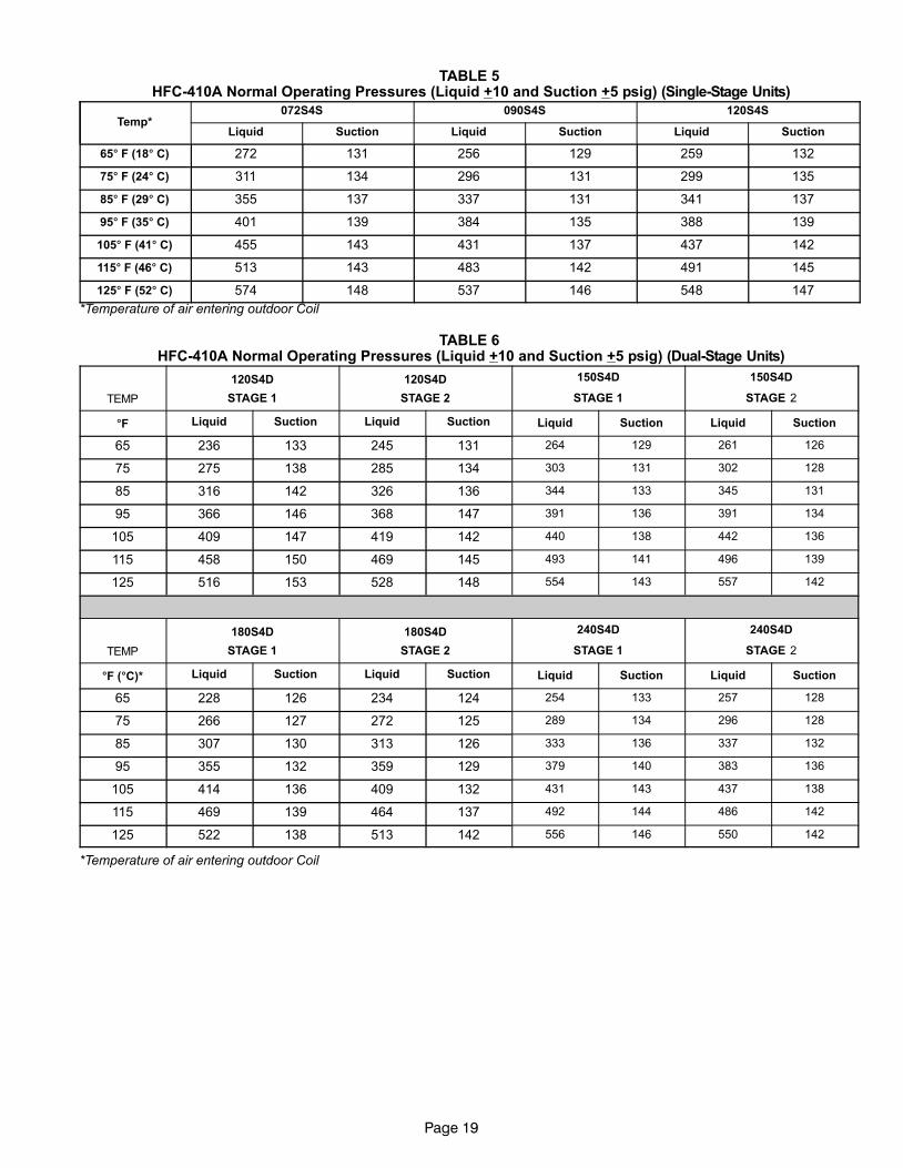
TABLE 5 HFC−410A Normal Operating Pressures (Liquid +10 and Suction +5 psig) (Single−Stage Units)
Temp*072S4S 090S4S 120S4S
Liquid Suction Liquid Suction Liquid Suction
65� F (18� C) 272 131 256 129 259 132
75� F (24� C) 311 134 296 131 299 135
85� F (29� C) 355 137 337 131 341 137
95� F (35� C) 401 139 384 135 388 139
105� F (41� C) 455 143 431 137 437 142
115� F (46� C) 513 143 483 142 491 145
125� F (52� C) 574 148 537 146 548 147
*Temperature of air entering outdoor Coil
TABLE 6 HFC−410A Normal Operating Pressures (Liquid +10 and Suction +5 psig) (Dual−Stage Units)
TEMP
120S4D
STAGE 1
120S4D
STAGE 2
150S4D
STAGE 1
150S4D
STAGE 2
�F Liquid Suction Liquid Suction Liquid Suction Liquid Suction
65 236 133 245 131 264 129 261 126
75 275 138 285 134 303 131 302 128
85 316 142 326 136 344 133 345 131
95 366 146 368 147 391 136 391 134
105 409 147 419 142 440 138 442 136
115 458 150 469 145 493 141 496 139
125 516 153 528 148 554 143 557 142
TEMP
180S4D
STAGE 1
180S4D
STAGE 2
240S4D
STAGE 1
240S4D
STAGE 2
�F (�C)* Liquid Suction Liquid Suction Liquid Suction Liquid Suction
65 228 126 234 124 254 133 257 128
75 266 127 272 125 289 134 296 128
85 307 130 313 126 333 136 337 132
95 355 132 359 129 379 140 383 136
105 414 136 409 132 431 143 437 138
115 469 139 464 137 492 144 486 142
125 522 138 513 142 556 146 550 142
*Temperature of air entering outdoor Coil
Page 20
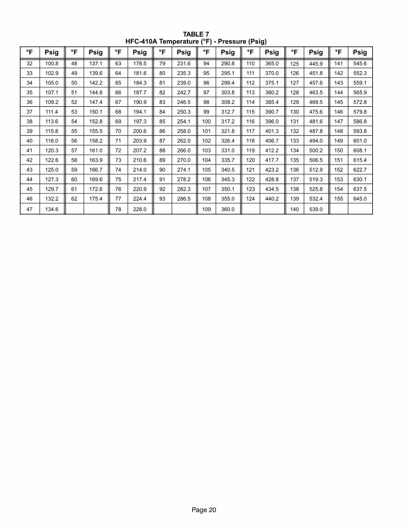
TABLE 7HFC−410A Temperature (°F) − Pressure (Psig)
°F Psig °F Psig °F Psig °F Psig °F Psig °F Psig °F Psig °F Psig
32 100.8 48 137.1 63 178.5 79 231.6 94 290.8 110 365.0 125 445.9 141 545.6
33 102.9 49 139.6 64 181.6 80 235.3 95 295.1 111 370.0 126 451.8 142 552.3
34 105.0 50 142.2 65 184.3 81 239.0 96 299.4 112 375.1 127 457.6 143 559.1
35 107.1 51 144.8 66 187.7 82 242.7 97 303.8 113 380.2 128 463.5 144 565.9
36 109.2 52 147.4 67 190.9 83 246.5 98 308.2 114 385.4 129 469.5 145 572.8
37 111.4 53 150.1 68 194.1 84 250.3 99 312.7 115 390.7 130 475.6 146 579.8
38 113.6 54 152.8 69 197.3 85 254.1 100 317.2 116 396.0 131 481.6 147 586.8
39 115.8 55 155.5 70 200.6 86 258.0 101 321.8 117 401.3 132 487.8 148 593.8
40 118.0 56 158.2 71 203.9 87 262.0 102 326.4 118 406.7 133 494.0 149 601.0
41 120.3 57 161.0 72 207.2 88 266.0 103 331.0 119 412.2 134 500.2 150 608.1
42 122.6 58 163.9 73 210.6 89 270.0 104 335.7 120 417.7 135 506.5 151 615.4
43 125.0 59 166.7 74 214.0 90 274.1 105 340.5 121 423.2 136 512.9 152 622.7
44 127.3 60 169.6 75 217.4 91 278.2 106 345.3 122 428.8 137 519.3 153 630.1
45 129.7 61 172.6 76 220.9 92 282.3 107 350.1 123 434.5 138 525.8 154 637.5
46 132.2 62 175.4 77 224.4 93 286.5 108 355.0 124 440.2 139 532.4 155 645.0
47 134.6 78 228.0 109 360.0 140 539.0
Page 21
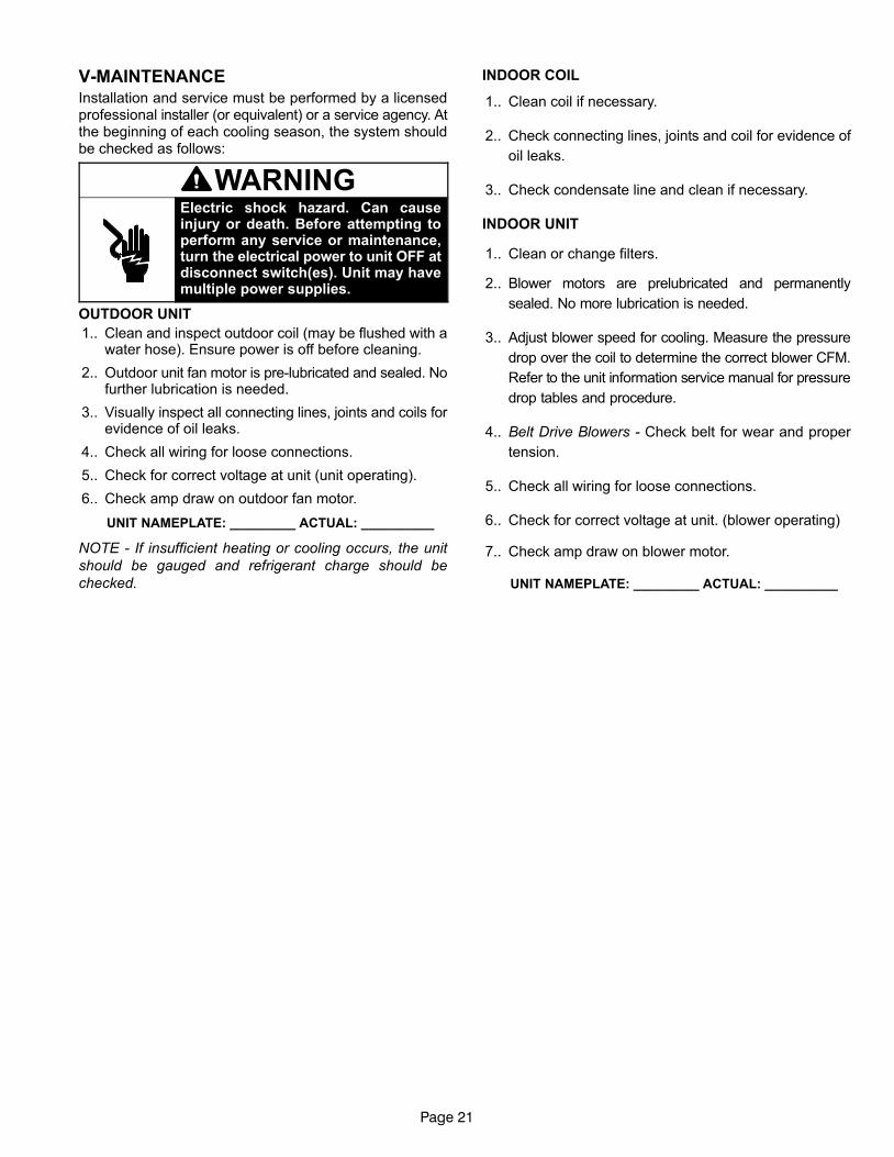
V−MAINTENANCEInstallation and service must be performed by a licensedprofessional installer (or equivalent) or a service agency. Atthe beginning of each cooling season, the system shouldbe checked as follows:
WARNINGElectric shock hazard. Can causeinjury or death. Before attempting toperform any service or maintenance,turn the electrical power to unit OFF atdisconnect switch(es). Unit may havemultiple power supplies.
OUTDOOR UNIT
1.. Clean and inspect outdoor coil (may be flushed with awater hose). Ensure power is off before cleaning.
2.. Outdoor unit fan motor is pre−lubricated and sealed. Nofurther lubrication is needed.
3.. Visually inspect all connecting lines, joints and coils forevidence of oil leaks.
4.. Check all wiring for loose connections.
5.. Check for correct voltage at unit (unit operating).
6.. Check amp draw on outdoor fan motor.
UNIT NAMEPLATE: _________ ACTUAL: __________
NOTE - If insufficient heating or cooling occurs, the unit
should be gauged and refrigerant charge should be
checked.
INDOOR COIL
1.. Clean coil if necessary.
2.. Check connecting lines, joints and coil for evidence of
oil leaks.
3.. Check condensate line and clean if necessary.
INDOOR UNIT
1.. Clean or change filters.
2.. Blower motors are prelubricated and permanently
sealed. No more lubrication is needed.
3.. Adjust blower speed for cooling. Measure the pressure
drop over the coil to determine the correct blower CFM.
Refer to the unit information service manual for pressure
drop tables and procedure.
4.. Belt Drive Blowers − Check belt for wear and proper
tension.
5.. Check all wiring for loose connections.
6.. Check for correct voltage at unit. (blower operating)
7.. Check amp draw on blower motor.
UNIT NAMEPLATE: _________ ACTUAL: __________
Page 22
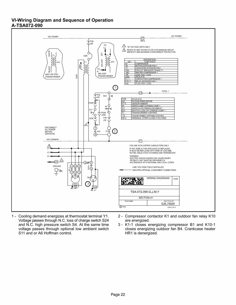
VI−Wiring Diagram and Sequence of OperationA−TSA072−090
1
2
3
1 − Cooling demand energizes at thermostat terminal Y1.Voltage passes through N.C. loss of charge switch S24and N.C. high pressure switch S4. At the same timevoltage passes through optional low ambient switchS11 and or A6 Hoffman control.
2 − Compressor contactor K1 and outdoor fan relay K10are energized.
3 − K1−1 closes energizing compressor B1 and K10−1closes energizing outdoor fan B4. Crankcase heaterHR1 is denergized.
Page 23
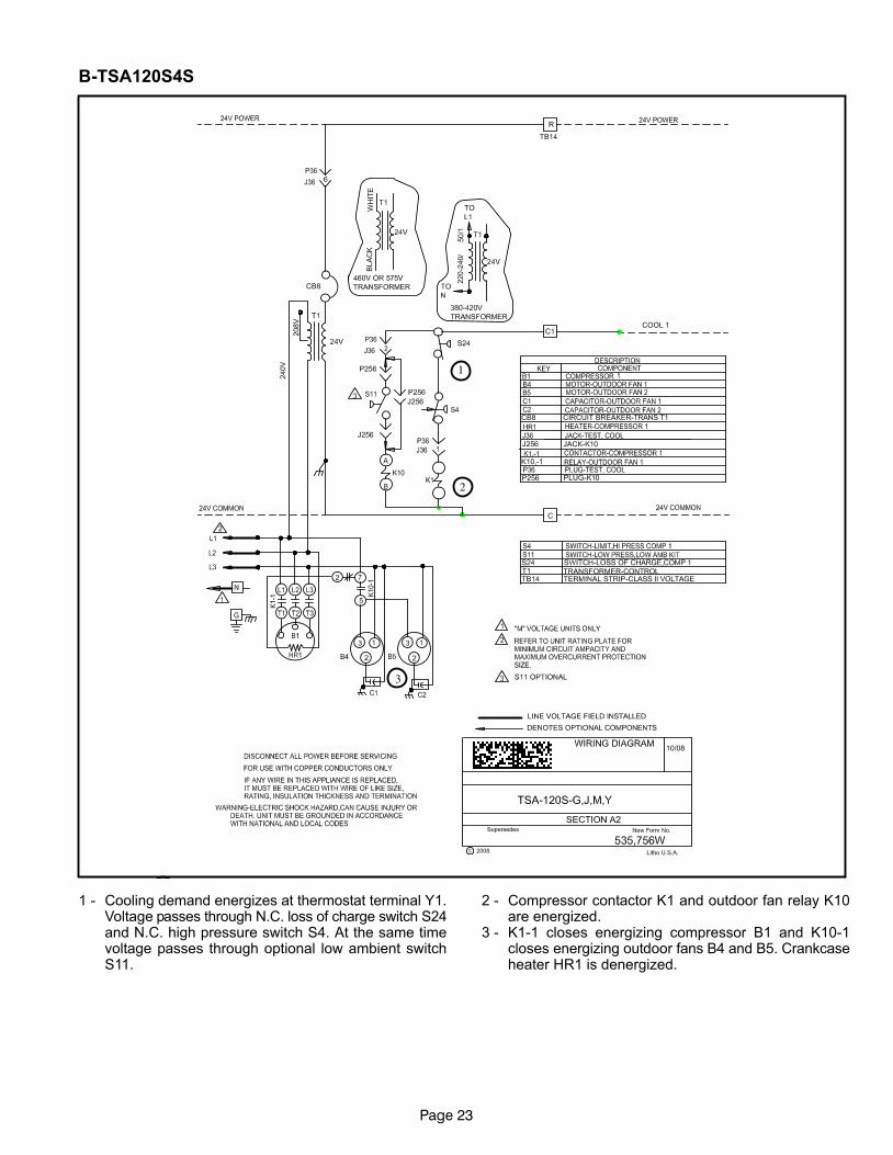
B−TSA120S4S
2
3
1
1 − Cooling demand energizes at thermostat terminal Y1.Voltage passes through N.C. loss of charge switch S24and N.C. high pressure switch S4. At the same timevoltage passes through optional low ambient switchS11.
2 − Compressor contactor K1 and outdoor fan relay K10are energized.
3 − K1−1 closes energizing compressor B1 and K10−1closes energizing outdoor fans B4 and B5. Crankcaseheater HR1 is denergized.
Page 24
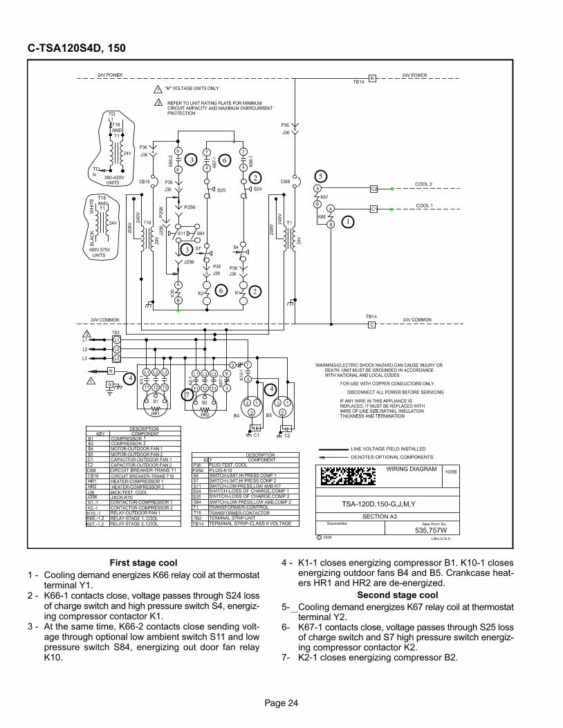
C−TSA120S4D, 150
5
6
2
3
1
4
2
3
4
6
7
First stage cool
1 − Cooling demand energizes K66 relay coil at thermostatterminal Y1.
2 − K66−1 contacts close, voltage passes through S24 lossof charge switch and high pressure switch S4, energiz-ing compressor contactor K1.
3 − At the same time, K66−2 contacts close sending volt-age through optional low ambient switch S11 and lowpressure switch S84, energizing out door fan relayK10.
4 − K1−1 closes energizing compressor B1. K10−1 closesenergizing outdoor fans B4 and B5. Crankcase heat-ers HR1 and HR2 are de−energized.
Second stage cool
5− Cooling demand energizes K67 relay coil at thermostatterminal Y2.
6− K67−1 contacts close, voltage passes through S25 lossof charge switch and S7 high pressure switch energiz-ing compressor contactor K2.
7− K2−1 closes energizing compressor B2.
Page 25
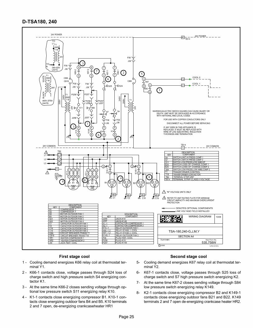
D−TSA180, 240
5
6
2
3
1
4
2
3
4
6
7
7
88
First stage cool
1 − Cooling demand energizes K66 relay coil at thermostat ter-
minal Y1.
2 − K66−1 contacts close, voltage passes through S24 loss of
charge switch and high pressure switch S4 energizing con-
tactor K1.
3 − At the same time K66−2 closes sending voltage through op-
tional low pressure switch S11 energizing relay K10.
4 − K1−1 contacts close energizing compressor B1. K10−1 con-
tacts close energizing outdoor fans B4 and B5. K10 terminals
2 and 7 open, de−energizing crankcaseheater HR1
Second stage cool
5− Cooling demand energizes K67 relay coil at thermostat ter-
minal Y2.
6− K67−1 contacts close, voltage passes through S25 loss of
charge switch and S7 high pressure switch energizing K2.
7− At the same time K67−2 closes sending voltage through S84
low pressure switch energizing relay K149.
8− K2−1 contacts close energizing compressor B2 and K149−1
contacts close energizing outdoor fans B21 and B22. K149
terminals 2 and 7 open de−energizing crankcase heater HR2.