Embed Size (px)
Citation preview
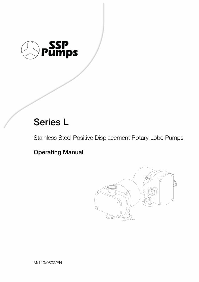
Series L
Stainless Steel Positive Displacement Rotary Lobe Pumps
Operating Manual
TD 246-034
M/110/0802/EN

8
9
Table of contents
1. General description ............................................................................. 10
2. Safety ................................................................................................... 112.1 Important information ...................................................................... 112.2 Warning signs ................................................................................. 112.3 Safety precautions .......................................................................... 12
3. Installation ........................................................................................... 133.1 Unpacking, Handling and Storage ................................................... 133.2 System design and installation ........................................................ 143.3 Flushing seal arrangement and pre-start up checks ........................ 17
4. Maintenance ........................................................................................ 194.1 Cleaning in place (CIP) .................................................................... 194.2 Maintenance schedule .................................................................... 204.3 Disassembly ................................................................................... 214.4 Assembly ........................................................................................ 244.5 Primary seals removal and fitting ..................................................... 294.6 Troubleshooting .............................................................................. 31
5. Technical data ...................................................................................... 325.1 Technical data ................................................................................. 325.2 Pumphead Clearance information ................................................... 33
6. Parts list ............................................................................................... 346.1 Series L Pump Range ..................................................................... 34
The information contained herein is correct at the time of issue but may be subject to change without prior notice.
10
TD 246-035
1.1 General description 1. General description
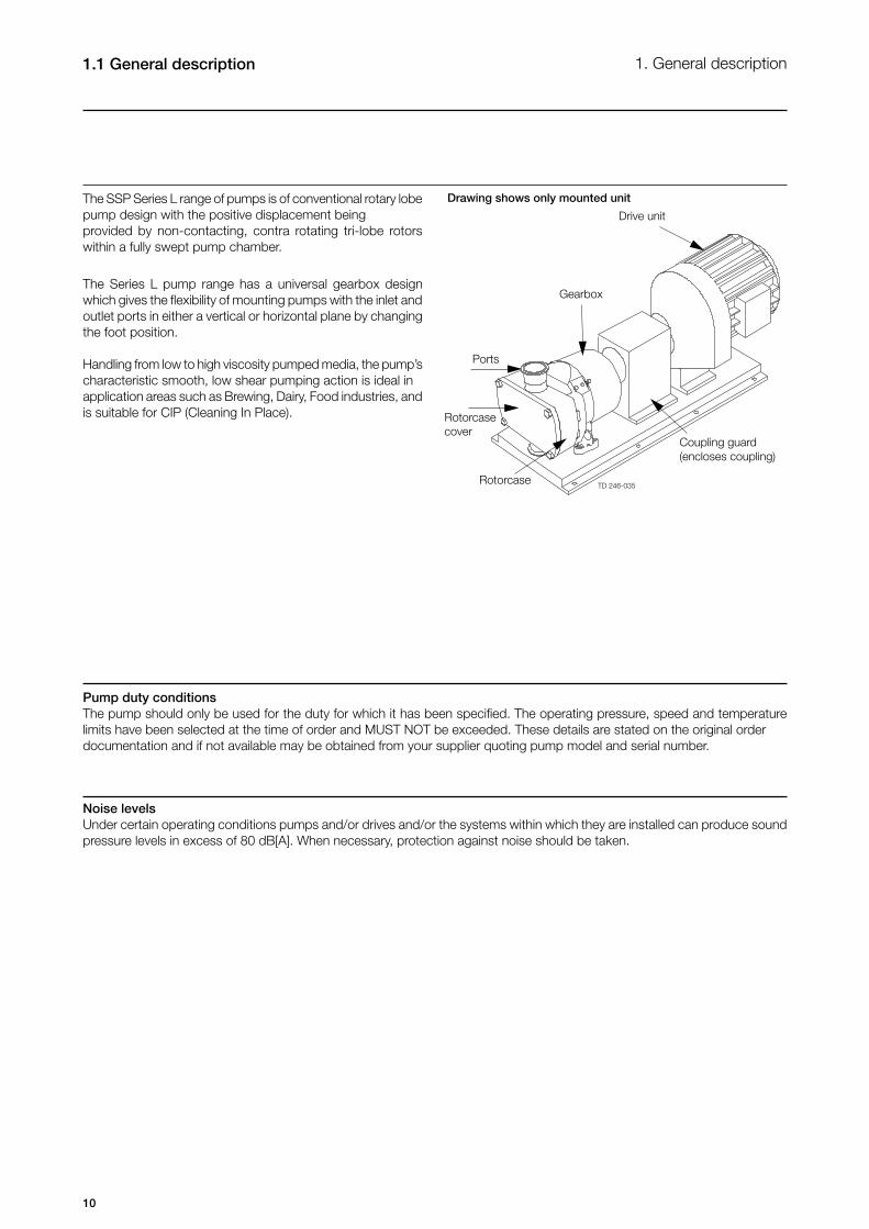
The SSP Series L range of pumps is of conventional rotary lobe pump design with the positive displacement being provided by non-contacting, contra rotating tri-lobe rotors within a fully swept pump chamber.
The Series L pump range has a universal gearbox design which gives the flexibility of mounting pumps with the inlet and outlet ports in either a vertical or horizontal plane by changing the foot position.
Handling from low to high viscosity pumped media, the pump’s characteristic smooth, low shear pumping action is ideal in application areas such as Brewing, Dairy, Food industries, and is suitable for CIP (Cleaning In Place).
Coupling guard(encloses coupling)
Rotorcase
Rotorcase cover
Ports
Gearbox
Drive unit
Noise levelsUnder certain operating conditions pumps and/or drives and/or the systems within which they are installed can produce sound pressure levels in excess of 80 dB[A]. When necessary, protection against noise should be taken.
Drawing shows only mounted unit
Pump duty conditionsThe pump should only be used for the duty for which it has been specified. The operating pressure, speed and temperature limits have been selected at the time of order and MUST NOT be exceeded. These details are stated on the original order documentation and if not available may be obtained from your supplier quoting pump model and serial number.
11
2. Safety 2.1 Important information2.2 Warning signs
Always read the manual before using the pump!
WARNING!Indicates that special procedures must be followed to avoid severe personal injury.
CAUTION!Indicates that special procedures must be followed to avoid damage to the pump.
NOTE!Indicates important information to simplify or clarify practices.
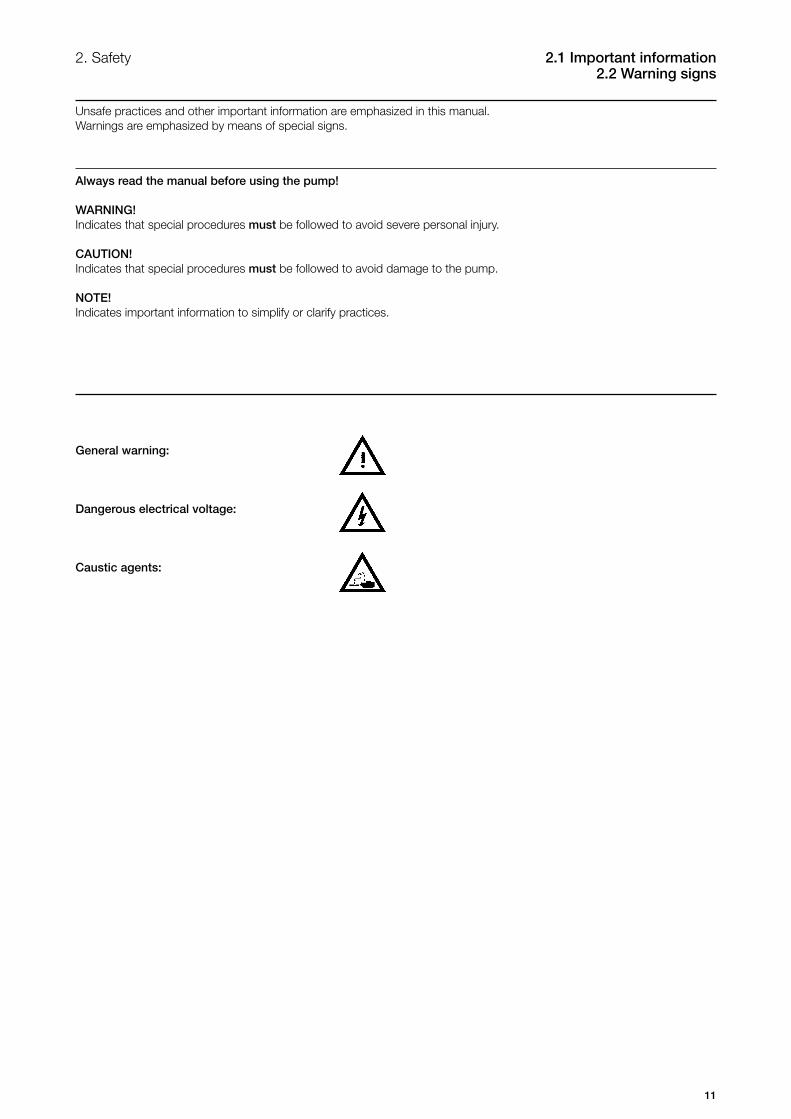
General warning:
Dangerous electrical voltage:
Caustic agents:
Unsafe practices and other important information are emphasized in this manual.Warnings are emphasized by means of special signs.
12
2.3 Safety precautions 2. Safety
Pay special attention to the instructions below so that severe personal injury or damage to the pump are avoided.
Installation- Always observe the technical data (see chapter 5).- Never start in the wrong direction of rotation with liquid in the pump.- Never put your hands or fingers inside the port connections or anywhere close to rotating shafts.
The pump must be electrically connected by authorised personnel (see the motor instructions supplied with the drive unit).
Operation- Always observe the technical data (see chapter 5).- Never touch the pump or the pipelines when pumping hot liquids or when sterilising.- Never stand on the pump or pipelines.- Never run the pump with either the suction side or the pressure side blocked.- Never put your hands or fingers inside the port connections or anywhere close to rotating parts.- Never run the pump unless fully assembled and all guards are securely fitted, i.e. pump head must not be removed from gearcase.
Only handle toxic and acidic liquids in accordance with the manufacturers instructions and recommendations.
Maintenance- Always observe the technical data (see chapter 5).- The pump must never be serviced when hot.- The pump and the pipelines must never be pressurised when the pump is being serviced.- Never put your hands or fingers inside the port connections or anywhere close to rotating parts.- Installation and operation of the pump must always comply with health and safety regulations. Any hazardous and/or hot, drained or leaked, liquid shall be disposed in compliance with health and safety regulations. If requested at the time of order, the equipment can be supplied with means of safe removal of any hazardous and/or hot, drained or leaked liquid.
- Always disconnect the power supply when the pump is being serviced.
13
TD 246-041 TD 246-042TD 246-043
TD 246-044
3. Installation 3.1 Unpacking, Handling and Storage
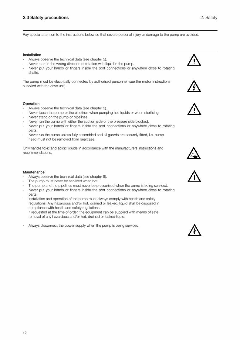
Step 1Refer to the pump weights guide (chapter 5) before selecting and using any lifting gear. The drawings show how the pump should be lifted.
Ensure that lifting equipment is correctly rated and used within these limits.
Bareshaft pumpPump with drive unit
Step 2On receipt always:- Check the delivery note against the goods received.- If motorised, check that the drive instructions are available.- Be careful not to discard any manuals that may be enclosed with the packaging.- Inspect the packing for signs of damage in transit.- Carefully remove the packing away from the pump.- Inspect the pump for any visible signs of damage.- Clean away the packing from the pump port connections.- Report any damage immediately to the carrier.
Step 3After receipt and inspection, if the pump is not to be installed immediately, the pump should be repacked and placed in suitable storage. The following points should be noted:
- Plastic or gasket type port covers should be left in place.- Pumps received wrapped with corrosion inhibiting treatment material should have wrapping replaced.- A clean, dry storage location free from vibration should be selected. If a moist or dusty atmosphere is used for storage, further protect the pump or unit with a suitable cover.- Rotate the pump/pump unit by hand weekly, to prevent bearing damage.- All associated ancillary equipment should be treated similarly.
14
3.2 System design and installation 3. Installation
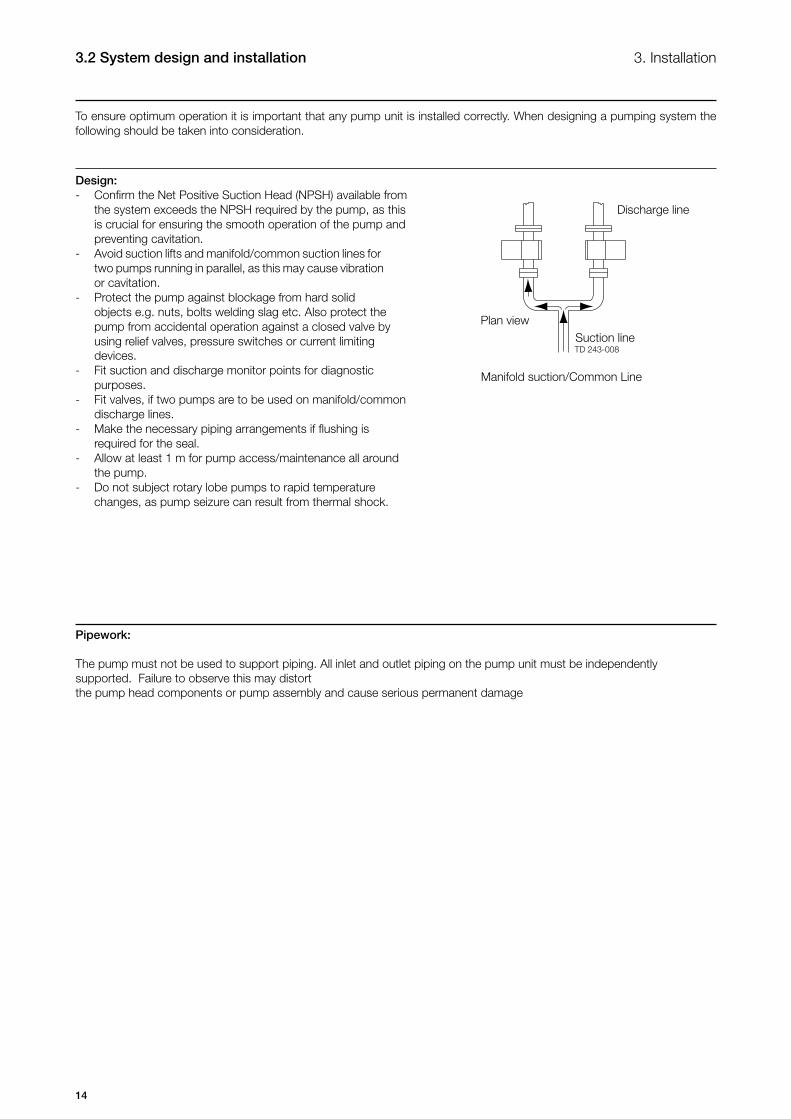
Design: - Confirm the Net Positive Suction Head (NPSH) available from the system exceeds the NPSH required by the pump, as this is crucial for ensuring the smooth operation of the pump and preventing cavitation.- Avoid suction lifts and manifold/common suction lines for two pumps running in parallel, as this may cause vibration or cavitation. - Protect the pump against blockage from hard solid objects e.g. nuts, bolts welding slag etc. Also protect the pump from accidental operation against a closed valve by using relief valves, pressure switches or current limiting devices.- Fit suction and discharge monitor points for diagnostic purposes.- Fit valves, if two pumps are to be used on manifold/common discharge lines.- Make the necessary piping arrangements if flushing is required for the seal.- Allow at least 1 m for pump access/maintenance all around the pump.- Do not subject rotary lobe pumps to rapid temperature changes, as pump seizure can result from thermal shock.
Discharge line
Plan viewSuction line
Pipework:
The pump must not be used to support piping. All inlet and outlet piping on the pump unit must be independently supported. Failure to observe this may distort the pump head components or pump assembly and cause serious permanent damage
Manifold suction/Common Line
To ensure optimum operation it is important that any pump unit is installed correctly. When designing a pumping system the following should be taken into consideration.
15
TD 246-014
3. Installation 3.2 System design and installation
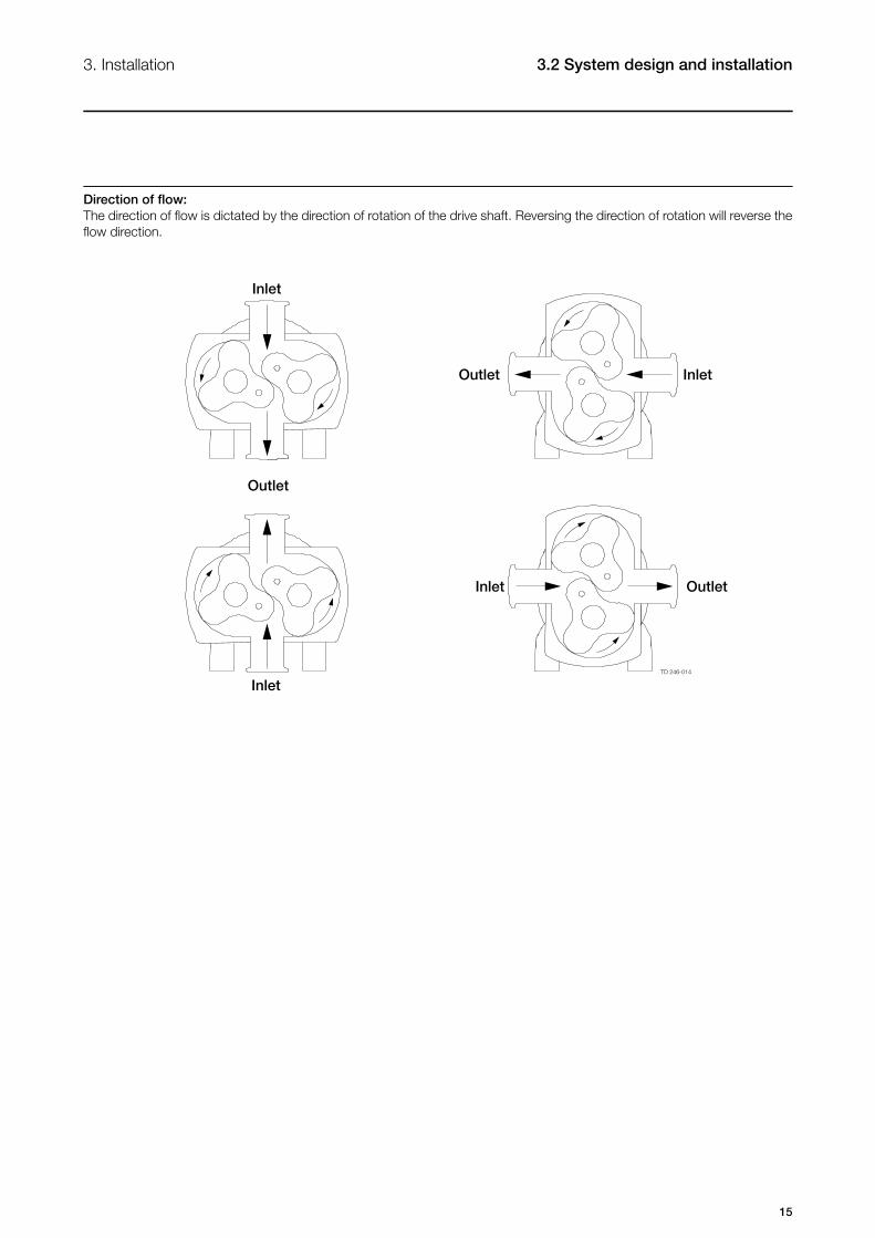
Direction of flow:The direction of flow is dictated by the direction of rotation of the drive shaft. Reversing the direction of rotation will reverse the flow direction.
Inlet
OutletInlet
Inlet
InletOutlet
Outlet
16
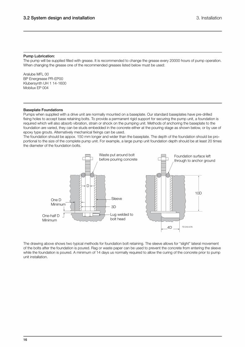
Baseplate FoundationsPumps when supplied with a drive unit are normally mounted on a baseplate. Our standard baseplates have pre-drilled fixing holes to accept base retaining bolts. To provide a permanent rigid support for securing the pump unit, a foundation is required which will also absorb vibration, strain or shock on the pumping unit. Methods of anchoring the baseplate to the foundation are varied, they can be studs embedded in the concrete either at the pouring stage as shown below, or by use of epoxy type grouts. Alternatively mechanical fixings can be used.The foundation should be appox. 150 mm longer and wider than the baseplate. The depth of the foundation should be pro-portional to the size of the complete pump unit. For example, a large pump unit foundation depth should be at least 20 times the diameter of the foundation bolts.
The drawing above shows two typical methods for foundation bolt retaining. The sleeve allows for “slight” lateral movement of the bolts after the foundation is poured. Rag or waste paper can be used to prevent the concrete from entering the sleeve while the foundation is poured. A minimum of 14 days us normally required to allow the curing of the concrete prior to pump unit installation.
3.2 System design and installation 3. Installation
Pump Lubrication:The pump will be supplied filled with grease. It is recommended to change the grease every 20000 hours of pump operation.When changing the grease one of the recommended greases listed below must be used:
Aralube MFL 00BP Energrease PR-EP00Klubersynth UH 1 14-1600Mobilux EP 004
Waste put around bolt before pouring concrete
Foundation surface left through to anchor ground
One DMinimum
One-half DMinimum
Sleeve
3D
Lug welded to bolt head
10D
4D
D
17
TD 246-047
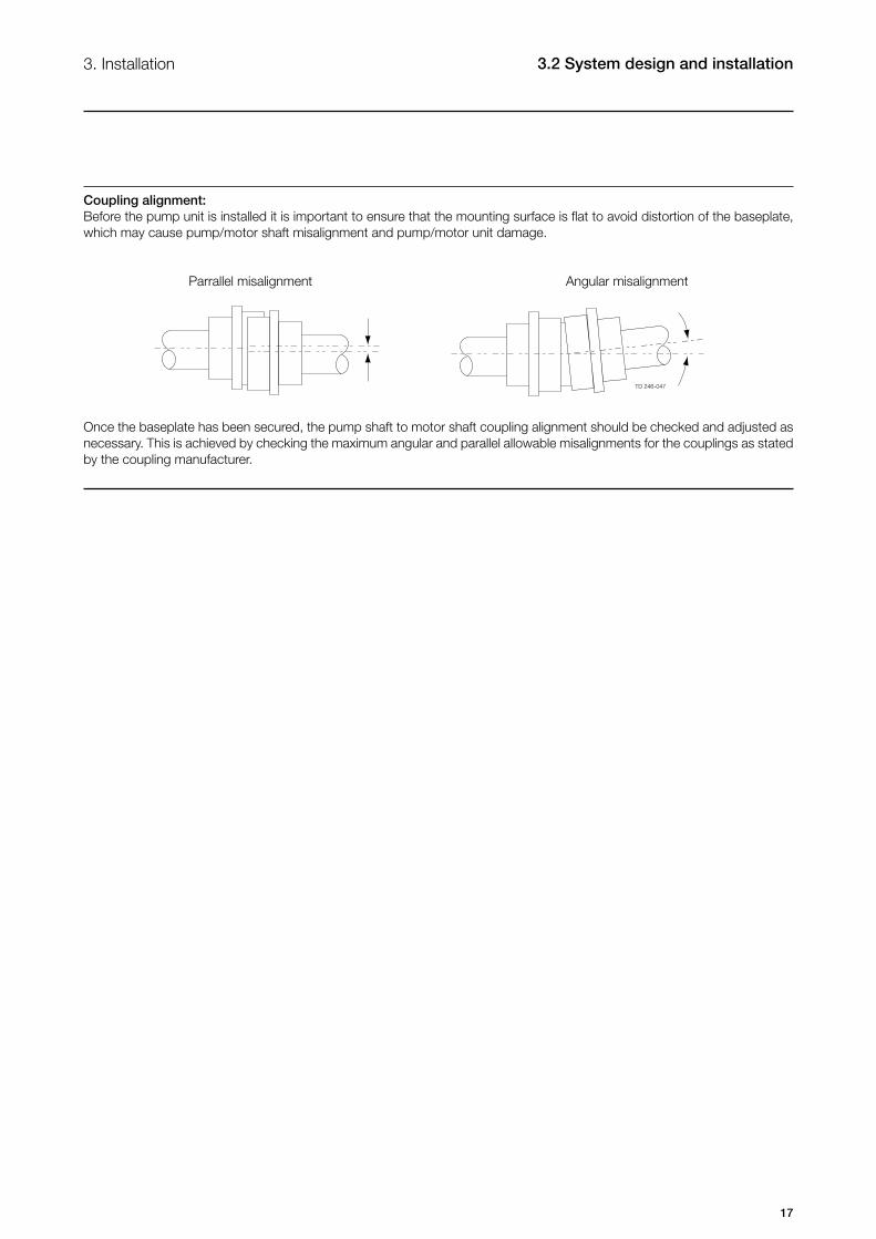
Coupling alignment:Before the pump unit is installed it is important to ensure that the mounting surface is flat to avoid distortion of the baseplate, which may cause pump/motor shaft misalignment and pump/motor unit damage.
Parrallel misalignment Angular misalignment
Once the baseplate has been secured, the pump shaft to motor shaft coupling alignment should be checked and adjusted as necessary. This is achieved by checking the maximum angular and parallel allowable misalignments for the couplings as stated by the coupling manufacturer.
3. Installation 3.2 System design and installation
18
TD 246-048
TD 246-049
3.3 Flushing seal arrangement and pre-start up checks 3. Installation
Step 4Flushing fluidThe choice of flushing fluid is dependent upon the fluid being pumped and duty conditions i.e. pressure and temperature. Usually water is used for cooling or flushing water soluble products. For single flushed mechanical seal arrangements the temperature of flush media should never allowed to exceed the maximum temperature of the pumped media. For advice on selecting a suitable flushing fluid please contact pump supplier.
Step 5Flushing pressure and flow rateSingle flushed mechanical seal 0.5 bar (7 psi) maximum. Any further increase in pressure will result in lip seal failure.
The flushing flow rate must be adequate to ensure that the temperature limitation of the seals is not exceeded. Contact your pump supplier for further information on the recommended flow.
Minimum flow rate required per shaft seal is 30 l/hr
Step 6Pre-start up checks- Check the pipework system has been purged to remove debris.- Check all obstructions have been removed from pipework and pump.- Check pump connections and pipework joints are tight.- Check lubrication levels are correct.- Check seal flushing is connected if applicable.- Check all safety guards are in place.- Check that inlet and outlet valves are open.
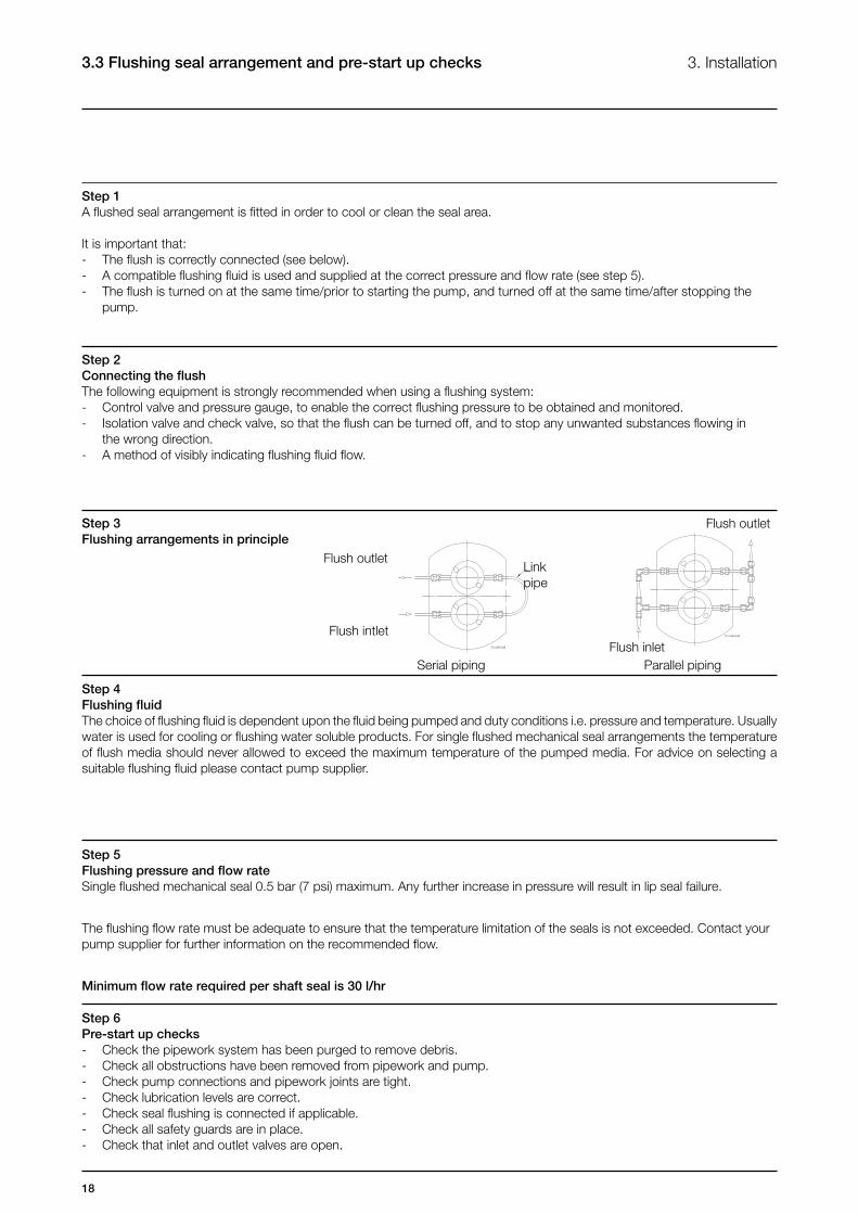
Step 3Flushing arrangements in principle
Flush outlet
Flush inlet
Flush outlet
Flush intlet
Linkpipe
Parallel pipingSerial piping
Step 1A flushed seal arrangement is fitted in order to cool or clean the seal area.
It is important that:- The flush is correctly connected (see below).- A compatible flushing fluid is used and supplied at the correct pressure and flow rate (see step 5).- The flush is turned on at the same time/prior to starting the pump, and turned off at the same time/after stopping the pump.
Step 2Connecting the flushThe following equipment is strongly recommended when using a flushing system:- Control valve and pressure gauge, to enable the correct flushing pressure to be obtained and monitored.- Isolation valve and check valve, so that the flush can be turned off, and to stop any unwanted substances flowing in the wrong direction.- A method of visibly indicating flushing fluid flow.
19
4. Maintenance 4.1 Cleaning in place (CIP)
The pump can be manually cleaned or cleaned in place (CIP). The following is an example of a typical CIP procedure. However specific advice for each application should be sought from the pump supplier.
Typical CIP procedure1. Flush through the system with cold water or bore water (6°C) (43°F).2. Run hot caustic soda (70-80°C) (158-176°F) at 2.5% dilution through the system for 20-30 minutes.3. Final flush through with cold water again.
Warnings
- Never touch the pump or the pipelines as they can be extremely hot!- Do not subject the pump to rapid temperature changes during CIP procedures, as pump seizure can result from thermal shock. A suitable by-pass is recommended.- Always rinse well with clean water after using a cleaning agent.
- Always use rubber gloves and protective goggles when handling caustic agents.- Always store/discharge cleaning agents in accordance with current rules/directives.
20
4.2 Maintenance schedule 4. Maintenance
It is advisable to install pressure gauges on both sides of the pump so that any problems within the pump/pipework can be monitored.
Maintenance scheduleYour weekly schedule should include:- Checking the seals for leakage.- Checking the lip seals for leakage.- Check pumping pressures.
In certain operational circumstances the pump will pose a thermal hazard and as such should not be touched during operation. After shutdown the pump unit should be allowed time to cool.
Part description Quantity
O-ring rotorcase cover 1
O-ring rotor sealing shaft end 2
O-ring rotor sealing rotor retainer end 2
Primary seals 2
Recommended Spare PartsThe table shows recommended spare parts that should be retained within your maintenance schedule.
Rotor nut O-ring Seal Replacement IntervalIt is recommended that the rotor nut O-ring seal is replaced every 12 months to maintain a bacteria tight seal.
Rotor Nut Seal InspectionPeriodically inspect the rotor nut O-ring seal for any discoloration, nicks, or cracks. If any of the defects above are noticed, the O-ring seal must be replaced. Inspection and replacement refer to the seal replacement procedure below.
Seal Replacement Procedure1. Remove rotor case cover (see 4.3, step 1).2. Undo rotor nuts and ensure components are dry before servicing.3. With a penlight, inspect rotor nut blind tapped hole for contamination. If soiled, refer to cleaning procedure below.4. Remove and discard rotor nut O-ring seal.5. Fit new rotor nut O-ring seal.6. Fit rotor nut and use a torque wrench to tighten to correct torque value (see table 5.1.3).7. Fit the rotor case cover.
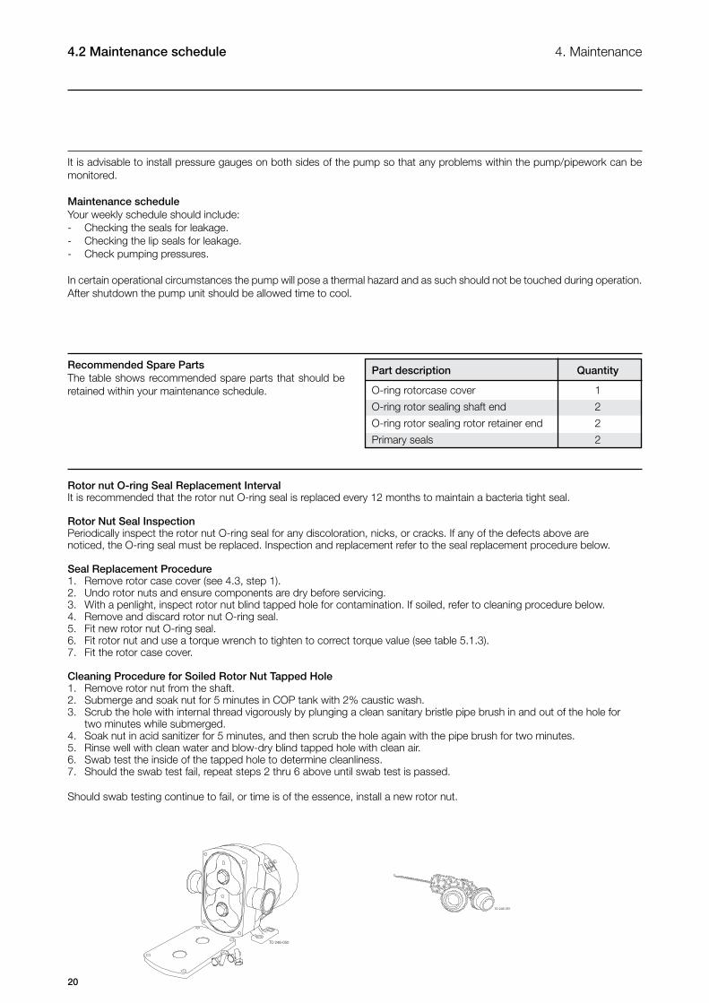
Cleaning Procedure for Soiled Rotor Nut Tapped Hole1. Remove rotor nut from the shaft.2. Submerge and soak nut for 5 minutes in COP tank with 2% caustic wash. 3. Scrub the hole with internal thread vigorously by plunging a clean sanitary bristle pipe brush in and out of the hole for two minutes while submerged.4. Soak nut in acid sanitizer for 5 minutes, and then scrub the hole again with the pipe brush for two minutes.5. Rinse well with clean water and blow-dry blind tapped hole with clean air.6. Swab test the inside of the tapped hole to determine cleanliness. 7. Should the swab test fail, repeat steps 2 thru 6 above until swab test is passed.
Should swab testing continue to fail, or time is of the essence, install a new rotor nut.
TD 246-050
TD 246-051
21
4. Maintenance 4.3 Disassembly
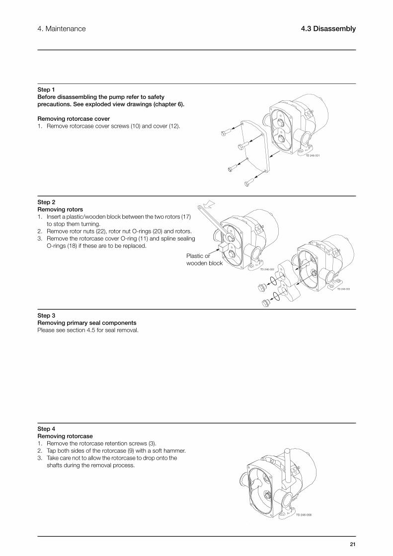
Step 1Before disassembling the pump refer to safety precautions. See exploded view drawings (chapter 6).
Removing rotorcase cover1. Remove rotorcase cover screws (10) and cover (12).
Step 2Removing rotors1. Insert a plastic/wooden block between the two rotors (17) to stop them turning.2. Remove rotor nuts (22), rotor nut O-rings (20) and rotors.3. Remove the rotorcase cover O-ring (11) and spline sealing O-rings (18) if these are to be replaced.
Plastic or wooden block
Step 3Removing primary seal componentsPlease see section 4.5 for seal removal.
Step 4Removing rotorcase1. Remove the rotorcase retention screws (3).2. Tap both sides of the rotorcase (9) with a soft hammer.3. Take care not to allow the rotorcase to drop onto the shafts during the removal process.
TD 246-001
TD 246-002
TD 246-068
TD 246-003
22
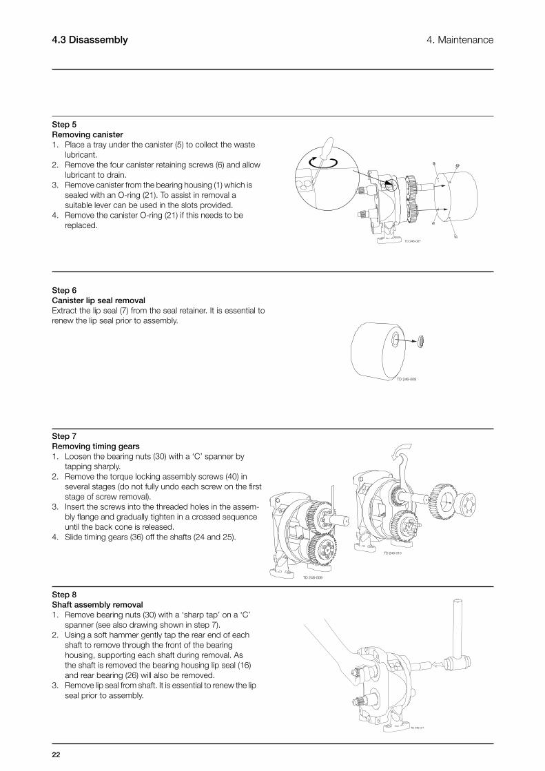
Step 7Removing timing gears1. Loosen the bearing nuts (30) with a ‘C’ spanner by tapping sharply.2. Remove the torque locking assembly screws (40) in several stages (do not fully undo each screw on the first stage of screw removal).3. Insert the screws into the threaded holes in the assem- bly flange and gradually tighten in a crossed sequence until the back cone is released. 4. Slide timing gears (36) off the shafts (24 and 25).
4.3 Disassembly 4. Maintenance
Step 5Removing canister1. Place a tray under the canister (5) to collect the waste lubricant.2. Remove the four canister retaining screws (6) and allow lubricant to drain. 3. Remove canister from the bearing housing (1) which is sealed with an O-ring (21). To assist in removal a suitable lever can be used in the slots provided.4. Remove the canister O-ring (21) if this needs to be replaced.
Step 8Shaft assembly removal1. Remove bearing nuts (30) with a ‘sharp tap’ on a ‘C’ spanner (see also drawing shown in step 7).2. Using a soft hammer gently tap the rear end of each shaft to remove through the front of the bearing housing, supporting each shaft during removal. As the shaft is removed the bearing housing lip seal (16) and rear bearing (26) will also be removed.3. Remove lip seal from shaft. It is essential to renew the lip seal prior to assembly.
Step 6Canister lip seal removalExtract the lip seal (7) from the seal retainer. It is essential to renew the lip seal prior to assembly.
TD 246-007
TD 246-008
TD 246-009
TD 246-010
TD 246-011
23
4. Maintenance 4.3 Disassembly
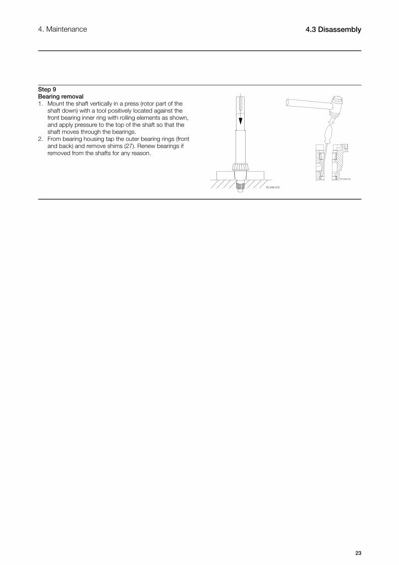
Step 9Bearing removal1. Mount the shaft vertically in a press (rotor part of the shaft down) with a tool positively located against the front bearing inner ring with rolling elements as shown, and apply pressure to the top of the shaft so that the shaft moves through the bearings.2. From bearing housing tap the outer bearing rings (front and back) and remove shims (27). Renew bearings if removed from the shafts for any reason.
TD 246-015
TD 246-016
24
4.4 Assembly 4. Maintenance
Take care not to damage shaft surfaces, in particular where bearings and lipseals will be locatedEnsure all fastenings are tightened to the torque settings as shown in Technical Data (section 5).
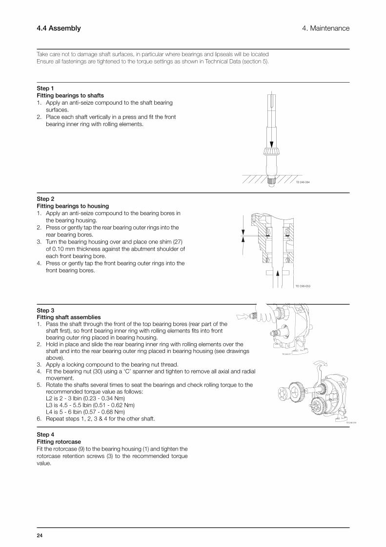
Step 1Fitting bearings to shafts1. Apply an anti-seize compound to the shaft bearing surfaces.2. Place each shaft vertically in a press and fit the front bearing inner ring with rolling elements.
Step 2Fitting bearings to housing1. Apply an anti-seize compound to the bearing bores in the bearing housing.2. Press or gently tap the rear bearing outer rings into the rear bearing bores.3. Turn the bearing housing over and place one shim (27) of 0.10 mm thickness against the abutment shoulder of each front bearing bore.4. Press or gently tap the front bearing outer rings into the front bearing bores.
Step 4Fitting rotorcaseFit the rotorcase (9) to the bearing housing (1) and tighten the rotorcase retention screws (3) to the recommended torque value.
TD 246-064
TD 246-053
TD 246-017
Step 3Fitting shaft assemblies1. Pass the shaft through the front of the top bearing bores (rear part of the shaft first), so front bearing inner ring with rolling elements fits into front bearing outer ring placed in bearing housing.2. Hold in place and slide the rear bearing inner ring with rolling elements over the shaft and into the rear bearing outer ring placed in bearing housing (see drawings above).3. Apply a locking compound to the bearing nut thread.4. Fit the bearing nut (30) using a ‘C’ spanner and tighten to remove all axial and radial movement.5. Rotate the shafts several times to seat the bearings and check rolling torque to the recommended torque value as follows: L2 is 2 - 3 lbin (0.23 - 0.34 Nm) L3 is 4.5 - 5.5 lbin (0.51 - 0.62 Nm) L4 is 5 - 6 lbin (0.57 - 0.68 Nm)6. Repeat steps 1, 2, 3 & 4 for the other shaft.
TD 246-018
25
4. Maintenance 4.4 Assembly
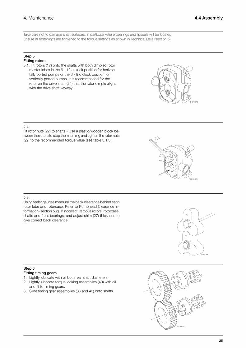
Step 5Fitting rotors5.1. Fit rotors (17) onto the shafts with both dimpled rotor master lobes in the 6 - 12 o’clock position for horizon tally ported pumps or the 3 - 9 o’clock position for vertically ported pumps. It is recommended for the rotor on the drive shaft (24) that the rotor dimple aligns with the drive shaft keyway.
5.2. Fit rotor nuts (22) to shafts - Use a plastic/wooden block be-tween the rotors to stop them turning and tighten the rotor nuts (22) to the recommended torque value (see table 5.1.3).
5.3. Using feeler gauges measure the back clearance behind each rotor lobe and rotorcase. Refer to Pumphead Clearance In-formation (section 5.2). If incorrect, remove rotors, rotorcase, shafts and front bearings, and adjust shim (27) thickness to give correct back clearance.
Step 6Fitting timing gears1. Lightly lubricate with oil both rear shaft diameters.2. Lightly lubricate torque locking assemblies (40) with oil and fit to timing gears.3. Slide timing gear assemblies (36 and 40) onto shafts.
Take care not to damage shaft surfaces, in particular where bearings and lipseals will be locatedEnsure all fastenings are tightened to the torque settings as shown in Technical Data (section 5).
TD 246-019
TD 246-020
TD 246-021
TD 246-054
26
TD 246-055
4. Maintenance4.4 Assembly
Take care not to damage shaft surfaces, in particular where bearings and lipseals will be locatedEnsure all fastenings are tightened to the torque settings as shown in Technical Data (section 5).
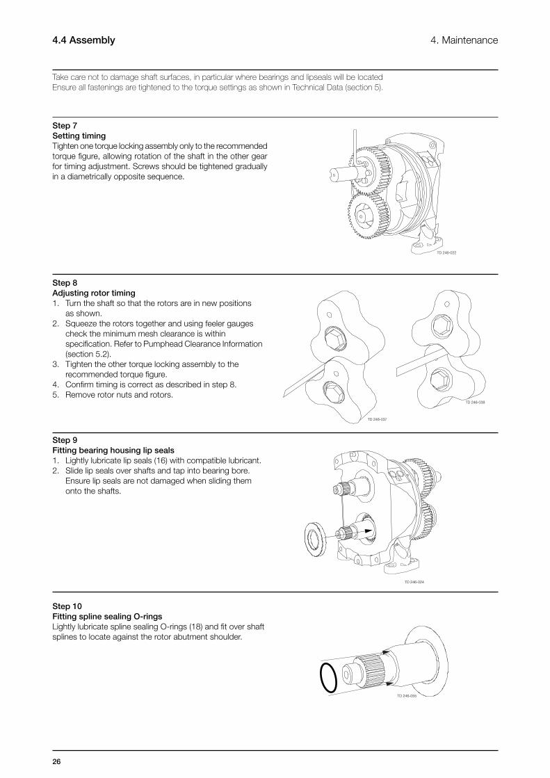
Step 7Setting timingTighten one torque locking assembly only to the recommended torque figure, allowing rotation of the shaft in the other gear for timing adjustment. Screws should be tightened gradually in a diametrically opposite sequence.
Step 8Adjusting rotor timing1. Turn the shaft so that the rotors are in new positions as shown.2. Squeeze the rotors together and using feeler gauges check the minimum mesh clearance is within specification. Refer to Pumphead Clearance Information (section 5.2). 3. Tighten the other torque locking assembly to the recommended torque figure.4. Confirm timing is correct as described in step 8.5. Remove rotor nuts and rotors.
Step 9Fitting bearing housing lip seals1. Lightly lubricate lip seals (16) with compatible lubricant. 2. Slide lip seals over shafts and tap into bearing bore. Ensure lip seals are not damaged when sliding them onto the shafts.
Step 10Fitting spline sealing O-ringsLightly lubricate spline sealing O-rings (18) and fit over shaft splines to locate against the rotor abutment shoulder.
TD 246-022
TD 246-037
TD 246-038
TD 246-024
27
4.4 Assembly4. Maintenance
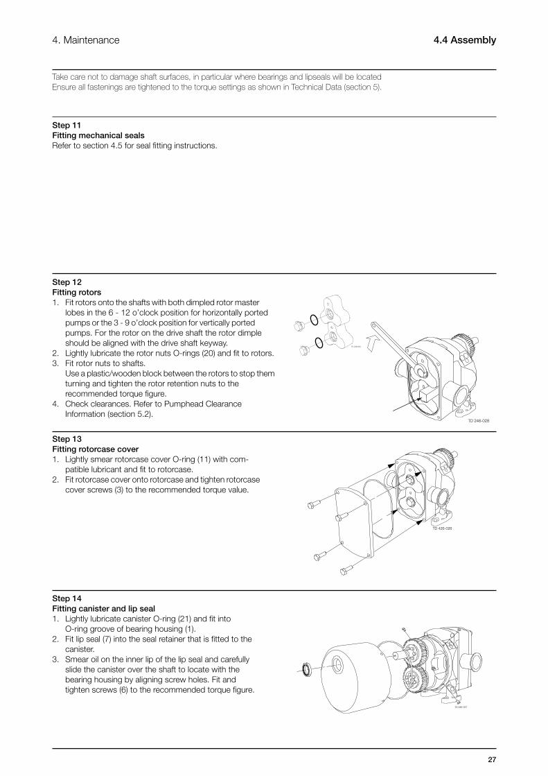
Step 12Fitting rotors1. Fit rotors onto the shafts with both dimpled rotor master lobes in the 6 - 12 o’clock position for horizontally ported pumps or the 3 - 9 o’clock position for vertically ported pumps. For the rotor on the drive shaft the rotor dimple should be aligned with the drive shaft keyway.2. Lightly lubricate the rotor nuts O-rings (20) and fit to rotors.3. Fit rotor nuts to shafts. Use a plastic/wooden block between the rotors to stop them turning and tighten the rotor retention nuts to the recommended torque figure.4. Check clearances. Refer to Pumphead Clearance Information (section 5.2).
Step 13Fitting rotorcase cover1. Lightly smear rotorcase cover O-ring (11) with com- patible lubricant and fit to rotorcase.2. Fit rotorcase cover onto rotorcase and tighten rotorcase cover screws (3) to the recommended torque value.
Step 14 Fitting canister and lip seal1. Lightly lubricate canister O-ring (21) and fit into O-ring groove of bearing housing (1).2. Fit lip seal (7) into the seal retainer that is fitted to the canister.3. Smear oil on the inner lip of the lip seal and carefully slide the canister over the shaft to locate with the bearing housing by aligning screw holes. Fit and tighten screws (6) to the recommended torque figure.
Step 11Fitting mechanical sealsRefer to section 4.5 for seal fitting instructions.
Take care not to damage shaft surfaces, in particular where bearings and lipseals will be locatedEnsure all fastenings are tightened to the torque settings as shown in Technical Data (section 5).
TD 246-025
TD 246-028
TD 426-026
TD 246-027
28
4. Maintenance4.4 Assembly
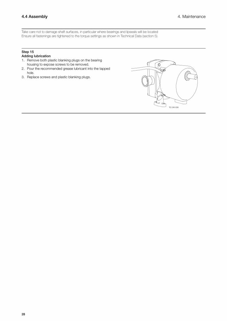
Step 15Adding lubrication1. Remove both plastic blanking plugs on the bearing housing to expose screws to be removed.2. Pour the recommended grease lubricant into the tapped hole.3. Replace screws and plastic blanking plugs.
Take care not to damage shaft surfaces, in particular where bearings and lipseals will be locatedEnsure all fastenings are tightened to the torque settings as shown in Technical Data (section 5).
TD 246-039
29
4.5 Primary seals removal and fitting4. Maintenance
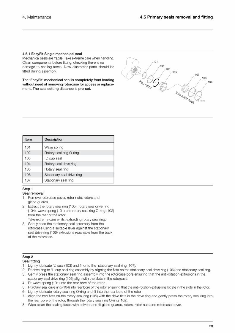
4.5.1 EasyFit Single mechanical sealMechanical seals are fragile. Take extreme care when handling. Clean components before fitting, checking there is no damage to sealing faces. New elastomer parts should be fitted during assembly.
The ‘EasyFit’ mechanical seal is completely front loading without need of removing rotorcase for access or replace-ment. The seal setting distance is pre-set.
Step 1Seal removal1. Remove rotorcase cover, rotor nuts, rotors and gland guards.2. Extract the rotary seal ring (105), rotary seal drive ring (104), wave spring (101) and rotary seal ring O-ring (102) from the rear of the rotor. Take extreme care whilst extracting rotary seal ring.3. Gently ease the stationary seal assembly from the rotorcase using a suitable lever against the stationary seal drive ring (106) extrusions reachable from the back of the rotorcase.
Step 2Seal fitting1. Lightly lubricate ‘L’ seal (103) and fit onto the stationary seal ring (107).2. Fit drive ring to ‘L’ cup seal ring assembly by aligning the flats on the stationary seal drive ring (106) and stationary seal ring.3. Gently press the stationary seal ring assembly into the rotorcase bore ensuring that the anti-rotation extrusions in the stationary seal drive ring (106) align with the slots in the rotorcase.4. Fit wave spring (101) into the rear bore of the rotor.5. Fit rotary seal drive ring (104) into rear bore of the rotor ensuring that the anti-rotation extrusions locate in the slots in the rotor.6. Lightly lubricate rotary seal ring O-ring and fit into the rear bore of the rotor7. Align the two flats on the rotary seal ring (105) with the drive flats in the drive ring and gently press the rotary seal ring into the rear bore of the rotor, through the rotary seal ring O-ring (102). 8. Wipe clean the sealing faces with solvent and fit gland guards, rotors, rotor nuts and rotorcase cover.
Item Description
101 Wave spring
102 Rotary seal ring O-ring
103 ‘L’ cup seal
104 Rotary seal drive ring
105 Rotary seal ring
106 Stationary seal drive ring
107 Stationary seal ring
101
104102
105
TD 246-070
107103
106Into rotorInto rotorcase
30
4.5 Primary seals removal and fitting 4. Maintenance
Step 1Seal removal1. Remove rotorcase cover, rotor nuts, rotors and gland guards.2. Extract the rotary seal ring (105), rotary seal drive ring (104), wave spring (101) and rotary seal ring O-ring (102) from the rear of the rotor. Take extreme care whilst extracting rotary seal ring.3. Drain seal housing (108) for any liquid and dispose drained liquid in accordance to existing legislation. 4. If only the mechanical seals are to be replaced, a suitable lever can be used to gently ease the stationary seal assembly from the rotorcase. If complete disassembly of the flushed seal components is necessary, remove the rotorcase complete with seal housing.5. Undo the seal housing retention nuts.6. Remove the seal housings and extract the lip seals from the seal housings.7. Remove the seal housing O-ring from the rotorcase.8. Gently ease the stationary seal assembly from the rotorcase using a suitable lever against the stationary seal drive ring extrusions reachable from the back of the rotorcase.
Step 2Seal fitting1. Lightly lubricate ‘L’ cup seal (103) and fit onto the stationary seal ring (107).2. Fit stationary seal drive ring (106) to ‘L’ cup seal face assembly by aligning the flats on the stationary seal drive ring and stationary seal ring.3. Gently press the stationary seal drive ring assembly into the rotorcase bore ensuring that the anti-rotation extrusions in the stationary seal drive ring align with the slots in the rotorcase.4. If the rotorcase has been removed, lightly lubricate the seal housing O-rings and fit to the rotorcase.5. Press new lip seals into the seal housings.6. Fit seal housings to the rotorcase and tighten the seal housing retention nuts to the recommended torque figure.7. Refit the rotorcase to the bearing housing.8. Fit wave spring (101) into the rear bore of the rotor.9. Fit rotary seal drive ring (104) into rear bore of the rotor ensuring that the anti-rotation extrusions locate in the slots in the rotor.10. Lightly lubricate rotay seal ring O-ring elastomer and fit into the rear bore of the rotor11. Align the two flats on the rotary seal ring (105) with the drive flats in the rotary seal drive ring (104) and gently press the rotary seal ring into the rear bore of the rotor, through the rotary seal ring O-ring (102). On the front face of the seal ring there is an alignment mark to show the position of the flats on the rear face.12. Wipe clean the sealing faces with solvent and fit gland guards, rotors, rotor nuts and rotorcase cover.
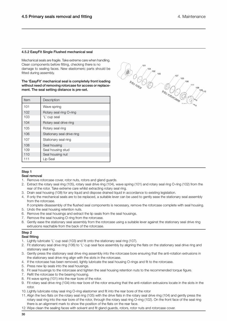
4.5.2 EasyFit Single Flushed mechanical seal
Mechanical seals are fragile. Take extreme care when handling. Clean components before fitting, checking there is no damage to sealing faces. New elastomeric parts should be fitted during assembly.
The ‘EasyFit’ mechanical seal is completely front loading without need of removing rotorcase for access or replace-ment. The seal setting distance is pre-set.
Item Description
101 Wave spring
102 Rotary seal ring O-ring 103 ‘L’ cup seal
104 Rotary seal drive ring
105 Rotary seal ring
106 Stationary seal drive ring
107 Stationary seal ring
108 Seal housing 109 Seal housing stud 110 Seal housing nut 111 Lip Seal
101
104102
105
TD 246-071
107103
106
111108
109110
Into rotorInto rotorcase
31
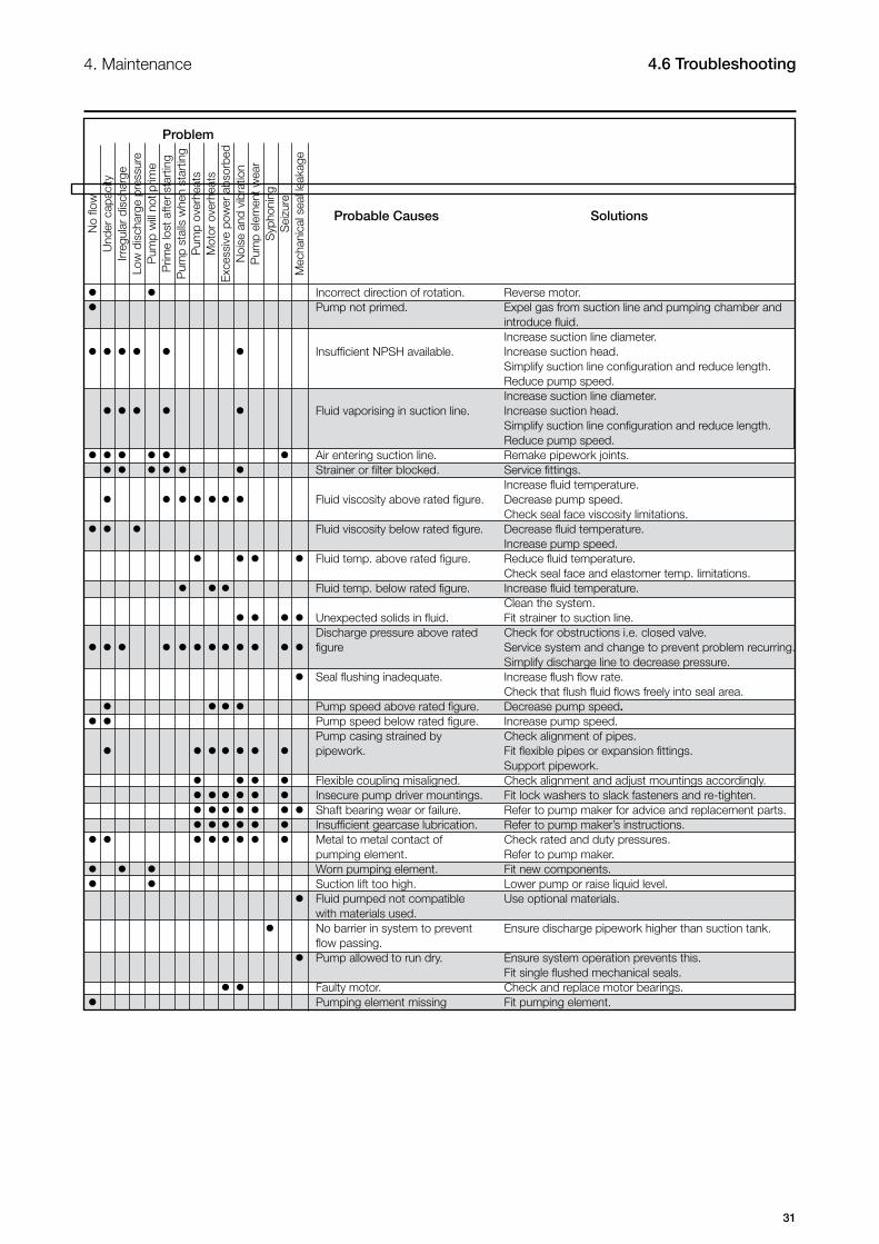
4. Maintenance 4.6 Troubleshooting
Problem
Probable Causes Solutions
ll Incorrect direction of rotation. Reverse motor.l Pump not primed. Expel gas from suction line and pumping chamber and introduce fluid. Increase suction line diameter.llllll Insufficient NPSH available. Increase suction head. Simplify suction line configuration and reduce length. Reduce pump speed. Increase suction line diameter.lllll Fluid vaporising in suction line. Increase suction head. Simplify suction line configuration and reduce length. Reduce pump speed.llllll Air entering suction line. Remake pipework joints.ll lll l Strainer or filter blocked. Service fittings. Increase fluid temperature.lllllll Fluid viscosity above rated figure. Decrease pump speed. Check seal face viscosity limitations.ll l Fluid viscosity below rated figure. Decrease fluid temperature. Increase pump speed. llllFluid temp. above rated figure. Reduce fluid temperature. Check seal face and elastomer temp. limitations.lll Fluid temp. below rated figure. Increase fluid temperature. Clean the system. llll Unexpected solids in fluid. Fit strainer to suction line. Discharge pressure above rated Check for obstructions i.e. closed valve.llllllllllllfigure Service system and change to prevent problem recurring. Simplify discharge line to decrease pressure. l Seal flushing inadequate. Increase flush flow rate. Check that flush fluid flows freely into seal area. l lll Pump speed above rated figure. Decrease pump speed.ll Pump speed below rated figure. Increase pump speed. Pump casing strained by Check alignment of pipes. l llllll pipework. Fit flexible pipes or expansion fittings. Support pipework. llll Flexible coupling misaligned. Check alignment and adjust mountings accordingly. llllll Insecure pump driver mountings. Fit lock washers to slack fasteners and re-tighten. lllll ll Shaft bearing wear or failure. Refer to pump maker for advice and replacement parts. llllll Insufficient gearcase lubrication. Refer to pump maker’s instructions.ll llllll Metal to metal contact of Check rated and duty pressures. pumping element. Refer to pump maker.l ll Worn pumping element. Fit new components.ll Suction lift too high. Lower pump or raise liquid level. lFluid pumped not compatible Use optional materials. with materials used. l No barrier in system to prevent Ensure discharge pipework higher than suction tank. flow passing. l Pump allowed to run dry. Ensure system operation prevents this. Fit single flushed mechanical seals. ll Faulty motor. Check and replace motor bearings.l Pumping element missing Fit pumping element.
No
flow
Und
er c
apac
ityIrr
egul
ar d
isch
arge
Low
dis
char
ge p
ress
ure
Pum
p w
ill no
t prim
eP
rime
lost
afte
r st
artin
gP
ump
stal
ls w
hen
star
ting
Pum
p ov
erhe
ats
Mot
or o
verh
eats
Exc
essi
ve p
ower
abs
orbe
dN
oise
and
vib
ratio
nP
ump
elem
ent w
ear
Syp
honi
ngS
eizu
reM
echa
nica
l sea
l lea
kage
32
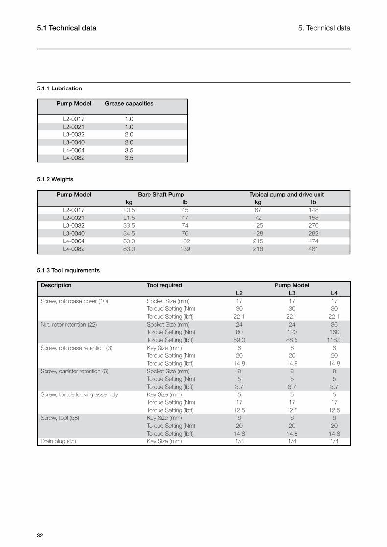
5.1 Technical data 5. Technical data
5.1.1 Lubrication
Pump Model Grease capacities
L2-0017 1.0 L2-0021 1.0 L3-0032 2.0 L3-0040 2.0 L4-0064 3.5 L4-0082 3.5
5.1.2 Weights
Pump Model Bare Shaft Pump Typical pump and drive unit kg lb kg lb L2-0017 20.5 45 67 148 L2-0021 21.5 47 72 158 L3-0032 33.5 74 125 276 L3-0040 34.5 76 128 282 L4-0064 60.0 132 215 474 L4-0082 63.0 139 218 481
5.1.3 Tool requirements
Description Tool required Pump Model L2 L3 L4Screw, rotorcase cover (10) Socket Size (mm) 17 17 17 Torque Setting (Nm) 30 30 30 Torque Setting (lbft) 22.1 22.1 22.1Nut, rotor retention (22) Socket Size (mm) 24 24 36 Torque Setting (Nm) 80 120 160 Torque Setting (lbft) 59.0 88.5 118.0Screw, rotorcase retention (3) Key Size (mm) 6 6 6 Torque Setting (Nm) 20 20 20 Torque Setting (lbft) 14.8 14.8 14.8Screw, canister retention (6) Socket Size (mm) 8 8 8 Torque Setting (Nm) 5 5 5 Torque Setting (lbft) 3.7 3.7 3.7Screw, torque locking assembly Key Size (mm) 5 5 5 Torque Setting (Nm) 17 17 17 Torque Setting (lbft) 12.5 12.5 12.5Screw, foot (58) Key Size (mm) 6 6 6 Torque Setting (Nm) 20 20 20 Torque Setting (lbft) 14.8 14.8 14.8Drain plug (45) Key Size (mm) 1/8 1/4 1/4
33
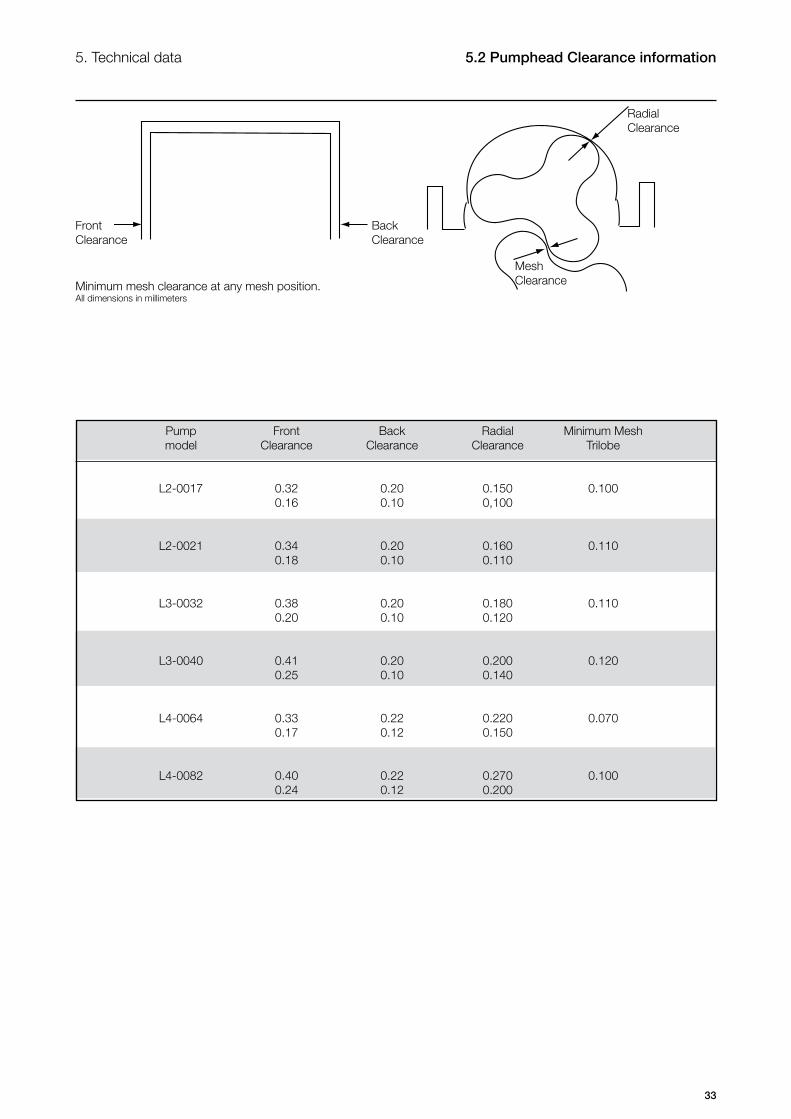
Pump Front Back Radial Minimum Mesh model Clearance Clearance Clearance Trilobe
L2-0017 0.32 0.20 0.150 0.100 0.16 0.10 0,100 L2-0021 0.34 0.20 0.160 0.110 0.18 0.10 0.110 L3-0032 0.38 0.20 0.180 0.110 0.20 0.10 0.120
L3-0040 0.41 0.20 0.200 0.120 0.25 0.10 0.140 L4-0064 0.33 0.22 0.220 0.070 0.17 0.12 0.150 L4-0082 0.40 0.22 0.270 0.100 0.24 0.12 0.200
Minimum mesh clearance at any mesh position. All dimensions in millimeters
5.2 Pumphead Clearance information5. Technical data
RadialClearance
MeshClearance
BackClearance
FrontClearance
34
6.1 Series L Pump Range 6. Parts list
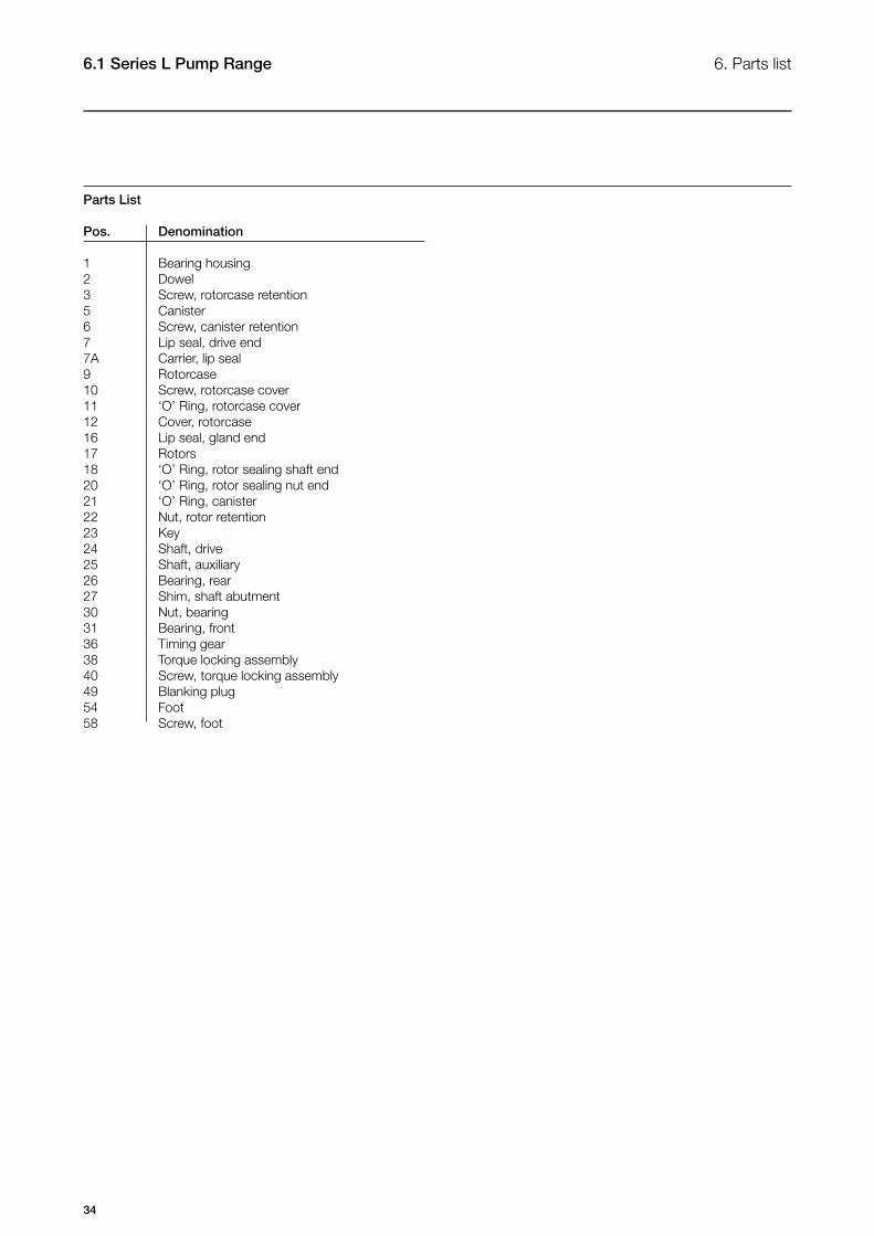
Parts List
Pos. Denomination
1 Bearing housing2 Dowel3 Screw, rotorcase retention5 Canister6 Screw, canister retention7 Lip seal, drive end7A Carrier, lip seal9 Rotorcase10 Screw, rotorcase cover 11 ‘O’ Ring, rotorcase cover12 Cover, rotorcase16 Lip seal, gland end17 Rotors18 ‘O’ Ring, rotor sealing shaft end20 ‘O’ Ring, rotor sealing nut end21 ‘O’ Ring, canister22 Nut, rotor retention23 Key24 Shaft, drive25 Shaft, auxiliary26 Bearing, rear27 Shim, shaft abutment30 Nut, bearing31 Bearing, front36 Timing gear38 Torque locking assembly40 Screw, torque locking assembly49 Blanking plug54 Foot58 Screw, foot
35
TD 246-046
7a
2
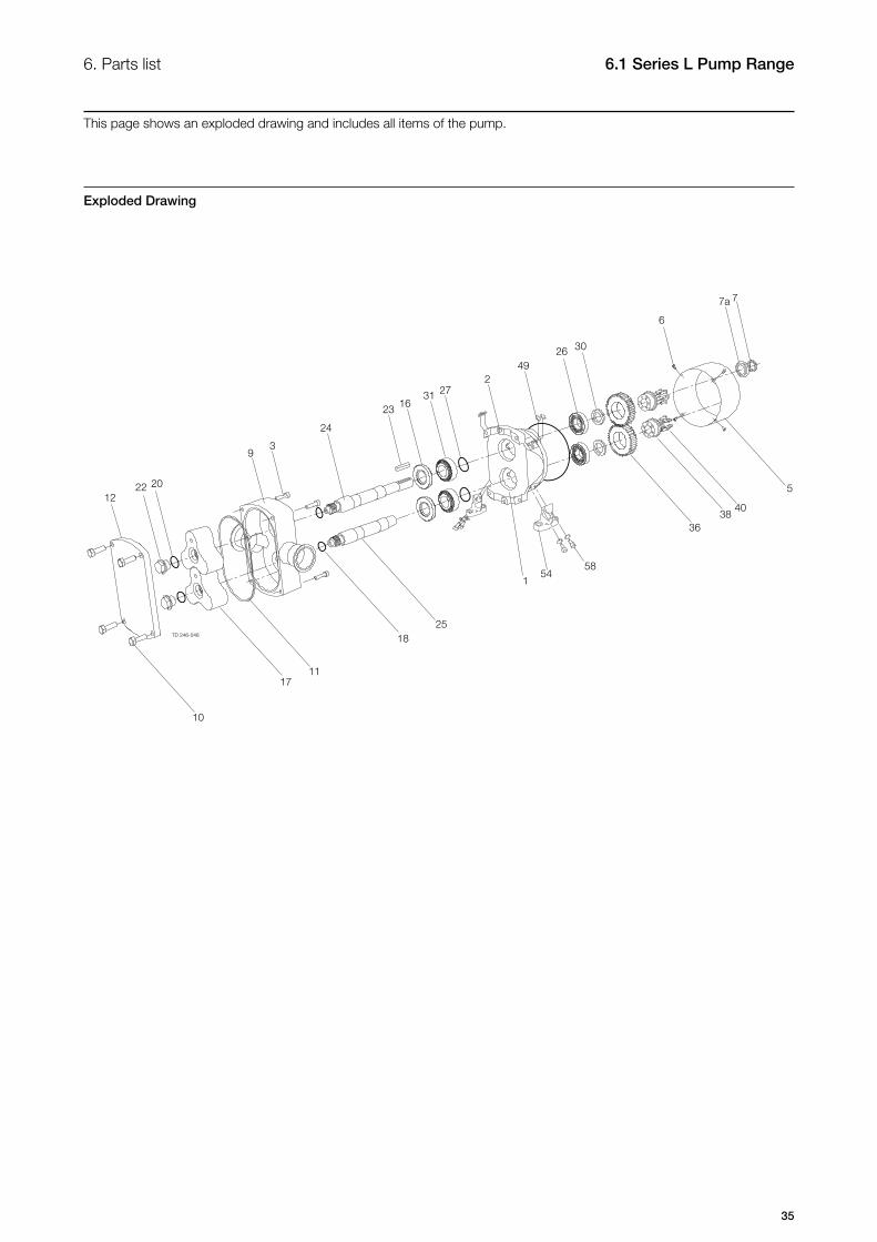
This page shows an exploded drawing and includes all items of the pump.
Exploded Drawing
6. Parts list 6.1 Series L Pump Range