Embed Size (px)
Citation preview

GRUNDFOS PRODUCT GUIDE
Magna
Series 2000 circulator pumps
2
Contents
Mission
Product dataMAGNA 4Duty range 4Characteristic features 4Benefits 4Applications 5Heating systems 5Pumped liquids 5Type key 6Performance range, MAGNA 6
Product rangeProduct range 7Pump selection 7Pump size 7Operating conditions 7Communication 7Control mode 7
Operating conditionsGeneral recommendations 8Liquid temperature 8Ambient conditions 8Maximum operating pressure 8Minimum inlet pressure 8Electrical data 9Sound pressure level 9
FunctionsFunctions 10Control modes (factory setting) 11AUTOADAPT 11Additional control and operating modes 11Proportional-pressure control 11Constant-pressure control 12Constant-curve duty 12Max. or min. curve duty 12Temperature influence 12Automatic night-time duty 13Additional operating modes two pumps in parallel 13Readings and settings on the pump 13Communication 14Digital input 14Digital output 15Analog input 15Bus communication via GENIbus 16Bus communication via LON 16Functions of expansion modules 16
ConstructionMotor and electronic controller 17Pump connections 17Paint 17Material specification 18
InstallationMechanical installation 19Electrical connection 20Cables 20Wiring diagram 20Additional protection 20Operating modes: 21Examples of connections 22
Curve conditionsCurve conditions 23
Performance curves/technical dataMAGNA 65-60 F 24MAGNA 40-120 F 26MAGNA 65-120 F 28
AccessoriesPackaged fitting sets 30Insulation kits 30Expansion modules for MAGNA 31GENI module 31LON module 32R100 32
Order dataMAGNA, cast iron 33MAGNA, stainless steel 33
Further product documentationWebCAPS 34WinCAPS 35

Magna
3
Mission
- to successfully develop, produce, and sell high quality pumps and pumping systems worldwide, contributing to a better quality of life and healthier environment
• One of the 3 largest pump companies in the world
• The second largest manufacturer of submersible motors in the world
• World headquarters in Denmark
• North American headquarters in Kansas City - Manufacturing in Fresno, California
• 73 companies in 41 countries
• More than 10 million motors and pumps produced annually worldwide
• North American companies operating in USA, Canada and Mexico
• Continuous reinvestment in growth and development enables the company to
BE responsible, THINK ahead, and INNOVATE
Bjerringbro, Denmark
Fresno, California Olathe, Kansas
Monterrey, Mexico Allentown, Pennsylvania Oakville, Ontario

4
MagnaProduct data
MAGNAThe MAGNA ranges of circulator pumps are specially designed for
• heating systems
• domestic hot-water systems (stainless-steel pump housing).
Duty range
Fig. 1 MAGNA pump
Characteristic features• AUTOADAPT
• proportional-pressure duty
• constant-pressure duty
• constant-curve duty
• max. or min. curve duty
• parallel connection of two pumps (requires additional expansion mod ule).
• no external motor protection required.
Benefits• low noise level
• safe selection
• simple installation
• low energy consumption, all MAGNA pumps are high efficiency with permanent magnet (PM) motors. Energy class "A' in European energy labeling schedule.
• in addition to this, the AUTOADAPT function ensures energy savings for MAGNA pumps
• long life and no maintenance
• external control and monitoring enabled via optional expansion modules.
Data MAGNAMaximum flow, Q 170 GPM
Maximum head, H 42 ft
Maximum system pressure 175 PSI (12 bar, 1.2 MPa)
Liquid temperature +50 to +230°F *(+15 to +110°C.)
GR
8384
Product data Magna
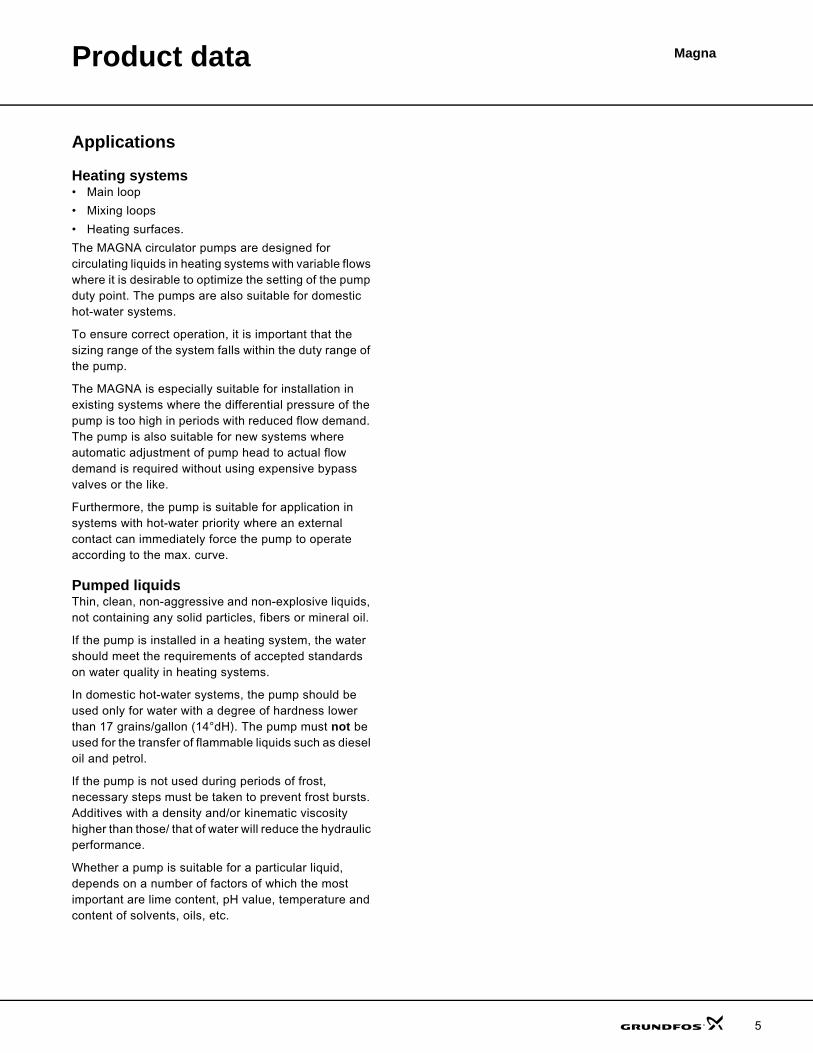
Applications
Heating systems • Main loop
• Mixing loops
• Heating surfaces.
The MAGNA circulator pumps are designed for circulating liquids in heating systems with variable flows where it is desirable to optimize the setting of the pump duty point. The pumps are also suitable for domestic hot-water systems.
To ensure correct operation, it is important that the sizing range of the system falls within the duty range of the pump.
The MAGNA is especially suitable for installation in existing systems where the differential pressure of the pump is too high in periods with reduced flow demand. The pump is also suitable for new systems where automatic adjustment of pump head to actual flow demand is required without using expensive bypass valves or the like.
Furthermore, the pump is suitable for application in systems with hot-water priority where an external contact can immediately force the pump to operate according to the max. curve.
Pumped liquidsThin, clean, non-aggressive and non-explosive liquids, not containing any solid particles, fibers or mineral oil.
If the pump is installed in a heating system, the water should meet the requirements of accepted standards on water quality in heating systems.
In domestic hot-water systems, the pump should be used only for water with a degree of hardness lower than 17 grains/gallon (14°dH). The pump must not be used for the transfer of flammable liquids such as diesel oil and petrol.
If the pump is not used during periods of frost, necessary steps must be taken to prevent frost bursts. Additives with a density and/or kinematic viscosity higher than those/ that of water will reduce the hydraulic performance.
Whether a pump is suitable for a particular liquid, depends on a number of factors of which the most important are lime content, pH value, temperature and content of solvents, oils, etc.
5
Product data Magna
6
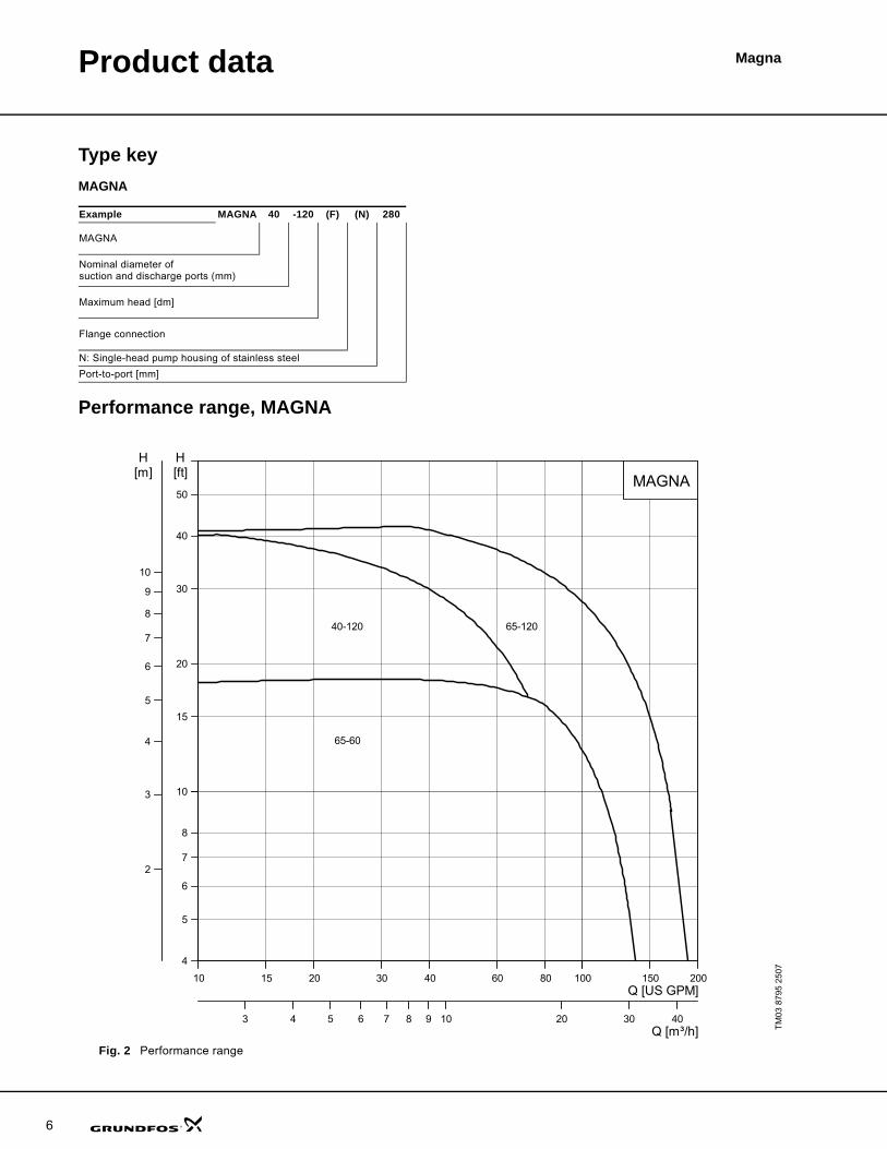
Type keyMAGNA
Performance range, MAGNA
Fig. 2 Performance range
Example MAGNA 40 -120 (F) (N) 280
MAGNA
Nominal diameter of suction and discharge ports (mm)
Maximum head [dm]
Flange connection
N: Single-head pump housing of stainless steel
Port-to-port [mm]
TM
03 8
795
2507
10 15 20 30 40 60 80 100100 150 200Q [US GPM]
4
5
6
7
8
1010
15
20
30
40
50
[ft]H
3 4 5 6 7 8 9 1010 20 30 40Q [m³/h]
2
3
4
5
6
7
8
9
1010
[m]H
MAGNA
40-120
65-60
65-120

Magna
7
Product range
Product range
Pump selection
Pump sizeSelection of pump size should be based on
• required maximum flow and
• maximum head loss in the system.
Operating conditionsThe operating conditions should be within published pump limits. When selecting a MAGNA pump following limitations shall be considered
• liquid temperature and ambient conditions
• minimum inlet pressure
• maximum operating pressure.
CommunicationThe requirements for external control or monitoring of the pump should be considered, such as access to
• speed control of pump or change of setpoint
• reading of pump data
• start/stop, fault indication or forced control to max. or min. curve.
Control modeIn general, Grundfos recommends
• the factory setting which is suitable for most installations
• proportional-pressure control in systems with relatively great head losses
• constant-pressure control in systems with relatively small head losses.
Fig. 3 Performance curve
Pump typeSupply voltage Port-to-port length Nominal pipe connection Flange connection
1 x 230 V [inch] [mm] 1.5" 2.5" GF15/26 GF 40/43 GF 53MAGNA 40-120 F (N) 8 ½ 216
MAGNA 65-60 F (N) 11 ½ 292
MAGNA 65-120 F (N) 11 ½ 292
TM
02 2
040
3301
Flow
Duty point
Head

8
MagnaOperating conditions
General recommendations
Liquid temperature
To avoid condensation in the terminal box and the stator, the liquid temperature must always be higher than the ambient temperature.
Ambient conditions
Maximum operating pressure175 psi (12 bar, 1.2 MPa).
Minimum inlet pressureThe following relative minimum pressures must be available at the pump inlet during operation:
Note: Actual inlet pressure + pump pressure against a closed valve must be lower than the maximum permissible system pressure.
MAGNAWater in heating systems
Water quality according to local standards.
Domestic hot water Degree of hardness up to 17 grains/gallon (14 d°H).
Water containing glycol Max. 50% glycol.Viscosity ≤ 0.3785 ft2/hr (10 mm2/s).
Application Time MAGNA
GeneralShort periods 230°F (+110°C)
Continuously 59 to 203°F (15 to 95°C)
Domestic hot-water systems Continuously 59 to 140°F (15 to 60°C)
Ambient temperatureduring operation
32 to 104 °F (0 to 40 °C)
Ambient temperatureduring storage/transport
–40 to 140 °F (–40 to 60 °C)
Relative air humidity Maximum 95 %.
Pump typeLiquid temperature
167 °F/75 °C 194 °F/90 °CInlet pressure [psi/bar]
MAGNA 40-120 F 13.1/0.9 17.5/1.2
MAGNA 65-60 F 13.1/0.9 17.5/1.2
MAGNA 65-120 F 13.1/0.9 17.5/1.2

Operating conditions Magna
Electrical dataMAGNA
Expansion module
Sound pressure level
Pump type Single-phase MAGNA, 40-120, 65-60, 65-120Enclosure class IP 44 (IEC 85)
Insulation class F
External start/stop inputExternal potential-free switch.Screened cable.Maximum contact load:5 V, 10 mA.
Setpoint signals GENI module
Signal output
Internal potential-free changeover contact.Screened cable.Maximum contact load:250 VAC, 2 A. Minimum contact load:5 VDC, 1 mA.
Bus input GENI moduleLON module
Supply voltage 1 x 230 V +/-10 %, 50/60 Hz, PE
The pump requires no external motor protection.
Earth leakage current Ileak < 3.5 mAThe leakage currents are measured in accordance with EN 60355-1.
EMC EN 61800-3.
Pump type Single-phase MAGNA, 40-120, 65-60, 65-120Sound pressure level ≤ 54 dB(A)
9
10
MagnaFunctions
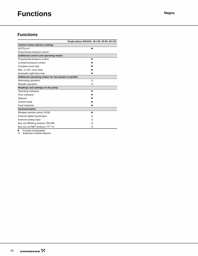
Functions
Function incorporated.Expansion module required.
Single-phase MAGNA, 40-120, 65-60, 65-120Control modes (factory setting)AUTOADAPT
Proportional-pressure control
Additional control and operating modesProportional-pressure control
Constant-pressure control
Constant-curve duty
Max. or min. curve duty
Automatic night-time duty
Additional operating modes for two pumps in parallelAlternating operation
Standby operation
Readings and settings on the pumpOperating indication
Flow indication
Setpoint
Control mode
Fault indication
CommunicationWireless remote control, R100
External digital input/output
External analog input
Bus via GENIbus protocol, RS-485
Bus via LonTalk® protocol, FTT 10
Functions Magna
Control modes (factory setting)The pumps have been factory-set to
• AUTOADAPT.
The setpoint is factory-set to approximately half of the maximum pump head.
The factory setting is suitable for most installations.
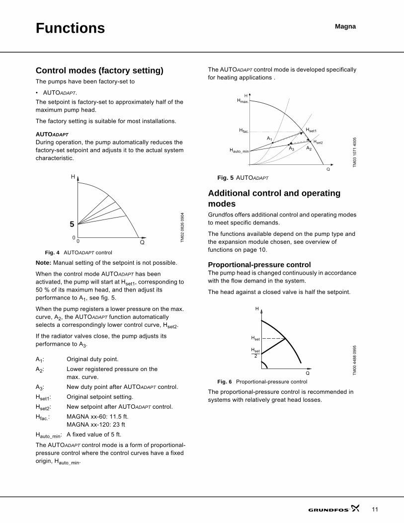
AUTOADAPT
During operation, the pump automatically reduces the factory-set setpoint and adjusts it to the actual system characteristic.
Fig. 4 AUTOADAPT control
Note: Manual setting of the setpoint is not possible.
When the control mode AUTOADAPT has been activated, the pump will start at Hset1, corresponding to 50 % of its maximum head, and then adjust its performance to A1, see fig. 5.
When the pump registers a lower pressure on the max. curve, A2, the AUTOADAPT function automatically selects a correspondingly lower control curve, Hset2.
If the radiator valves close, the pump adjusts its performance to A3.
The AUTOADAPT control mode is a form of proportional-pressure control where the control curves have a fixed origin, Hauto_min.
The AUTOADAPT control mode is developed specifically for heating applications .
Fig. 5 AUTOADAPT
Additional control and operating modesGrundfos offers additional control and operating modes to meet specific demands.
The functions available depend on the pump type and the expansion module chosen, see overview of functions on page 10.
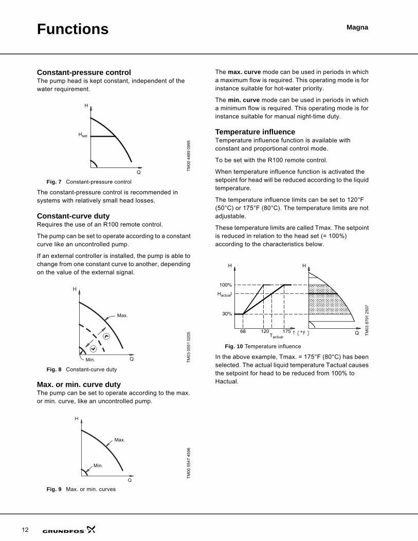
Proportional-pressure controlThe pump head is changed continuously in accordance with the flow demand in the system.
The head against a closed valve is half the setpoint.
Fig. 6 Proportional-pressure control
The proportional-pressure control is recommended in systems with relatively great head losses.
TM
02 0
826
0904
A1: Original duty point.
A2: Lower registered pressure on the max. curve.
A3: New duty point after AUTOADAPT control.
Hset1: Original setpoint setting.
Hset2: New setpoint after AUTOADAPT control.
Hfac.: MAGNA xx-60: 11.5 ft. MAGNA xx-120: 23 ft
Hauto_min: A fixed value of 5 ft.
H
Q00
1.55
TM
03 1
071
4005
TM
00 4
488
0995
Q
H
Hmax.
Hfac.
A1
A3 A2
Hset1
Hset2
Hauto_min
2
H
Q
Hset
Hset
11
Functions Magna
12
Constant-pressure controlThe pump head is kept constant, independent of the water requirement.
Fig. 7 Constant-pressure control
The constant-pressure control is recommended in systems with relatively small head losses.
Constant-curve dutyRequires the use of an R100 remote control.
The pump can be set to operate according to a constant curve like an uncontrolled pump.
If an external controller is installed, the pump is able to change from one constant curve to another, depending on the value of the external signal.
Fig. 8 Constant-curve duty
Max. or min. curve dutyThe pump can be set to operate according to the max. or min. curve, like an uncontrolled pump.
Fig. 9 Max. or min. curves
The max. curve mode can be used in periods in which a maximum flow is required. This operating mode is for instance suitable for hot-water priority.
The min. curve mode can be used in periods in which a minimum flow is required. This operating mode is for instance suitable for manual night-time duty.
Temperature influenceTemperature influence function is available with constant and proportional control mode.
To be set with the R100 remote control.
When temperature influence function is activated the setpoint for head will be reduced according to the liquid temperature.
The temperature influence limits can be set to 120°F (50°C) or 175°F (80°C). The temperature limits are not adjustable.
These temperature limits are called Tmax. The setpoint is reduced in relation to the head set (= 100%) according to the characteristics below.
Fig. 10 Temperature influence
In the above example, Tmax. = 175°F (80°C) has been selected. The actual liquid temperature Tactual causes the setpoint for head to be reduced from 100% to Hactual.
TM
00 4
489
0995
TM
03 0
551
0205
TM
00 5
547
4596
H
Q
Hset
H
Q
Max.
Min.
Q
H
Max.
Min.
TM
03 8
791
2507
30%
100%
FT17512068
H H
Q
Hactual
Tactual
Functions Magna
The temperature influence function requires:
• Proportional- or constant-pressure control mode.
• The pump must be installed in the supply side pipe.
• System with supply pipe temperature control.
Temperature influence is suitable in:
• systems with variable flows (e.g. two-pipe heating systems), in which the activation of the temperature influence function will ensure a further reduction of the pump performance in periods with small heating demands and consequently a reduced supply pipe temperature.
• systems with almost constant flows (e.g. one-pipe heating systems and radiant floor heating systems), in which variable heating demands cannot be regis-tered as changes in the head as is the case with two-pipe heating systems. In such systems, the pump performance can only be adjusted by activat-ing the temperature influence function.
Selection of Tmax.
In systems with a supply pipe temperature of:
• up to and including 131°F (55°C), select Tmax. = 120°F (50°C),
• above 131°F (55°C), select Tmax. = 175°F (80°C).
Automatic night-time dutyWhen automatic night-time duty has been selected, the pump will change automatically between normal duty and night-time duty. Changeover between normal duty and night-time duty takes place as a result of the supply pipe temperature measured by an integrated temperature sensor.
The automatic changeover to night-time duty takes place when the temperature sensor registers a supply pipe temperature drop of more than 18-27°F (10-15°C) within approx. 2 hours. The required temperature drop is a minimum of 18-27°F (10-15°C).
Changeover to normal duty takes place without a time lag when the temperature has increased by approx. 18°F (10°C).
Additional operating modes two pumps in parallelThe following operating modes are available for two pumps in parallel if both pumps are equipped with optional GENI module:
Alternating operation Pump operation alternates every 24 hours. If the duty pump stops due to a fault, the other pump starts.
Standby operation One pump operates continuously. In order to prevent seizing-up, the standby pump starts at a fixed frequency (every 24 hours) and runs for a short period. If the duty pump stops due to a fault, the standby pump starts.
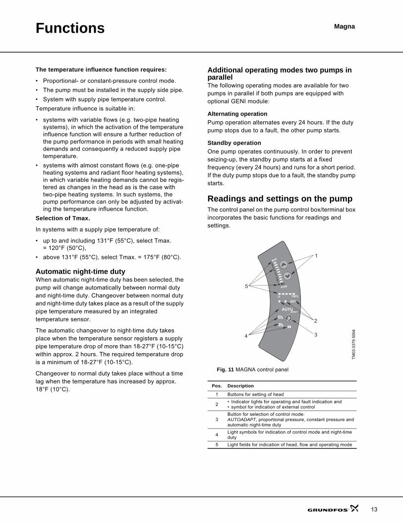
Readings and settings on the pumpThe control panel on the pump control box/terminal box incorporates the basic functions for readings and settings.
Fig. 11 MAGNA control panel
TM
03 0
379
5004
Pos. Description
1 Buttons for setting of head
2 • Indicator lights for operating and fault indication and • symbol for indication of external control
3Button for selection of control mode:AUTOADAPT, proportional pressure, constant pressure and automatic night-time duty
4 Light symbols for indication of control mode and night-time duty
5 Light fields for indication of head, flow and operating mode
AUTO
EXT
100%
MAX
STOPH
Q
5
4
1
2
3
ADAPT
13
Functions Magna
14
CommunicationMAGNA pump enables communication via
• wireless remote control, R100
• connection to an external alarm device
• digital input/output
• analog input.
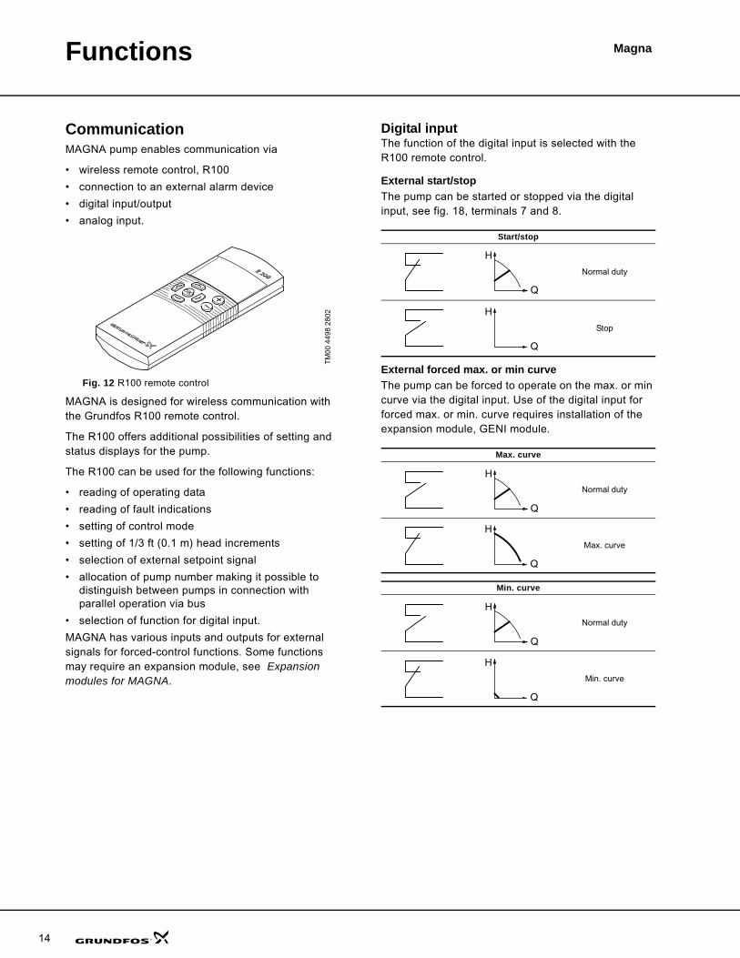
Fig. 12 R100 remote control
MAGNA is designed for wireless communication with the Grundfos R100 remote control.
The R100 offers additional possibilities of setting and status displays for the pump.
The R100 can be used for the following functions:
• reading of operating data
• reading of fault indications
• setting of control mode
• setting of 1/3 ft (0.1 m) head increments
• selection of external setpoint signal
• allocation of pump number making it possible to distinguish between pumps in connection with parallel operation via bus
• selection of function for digital input.
MAGNA has various inputs and outputs for external signals for forced-control functions. Some functions may require an expansion module, see Expansion modules for MAGNA.
Digital inputThe function of the digital input is selected with the R100 remote control.
External start/stopThe pump can be started or stopped via the digital input, see fig. 18, terminals 7 and 8.
External forced max. or min curve The pump can be forced to operate on the max. or min curve via the digital input. Use of the digital input for forced max. or min. curve requires installation of the expansion module, GENI module.
TM
00 4
498
2802
Start/stop
Normal duty
Stop
Max. curve
Normal duty
Max. curve
Min. curve
Normal duty
Min. curve
Q
H
Q
H
Q
H
Q
H
Q
H
Q
H
Functions Magna
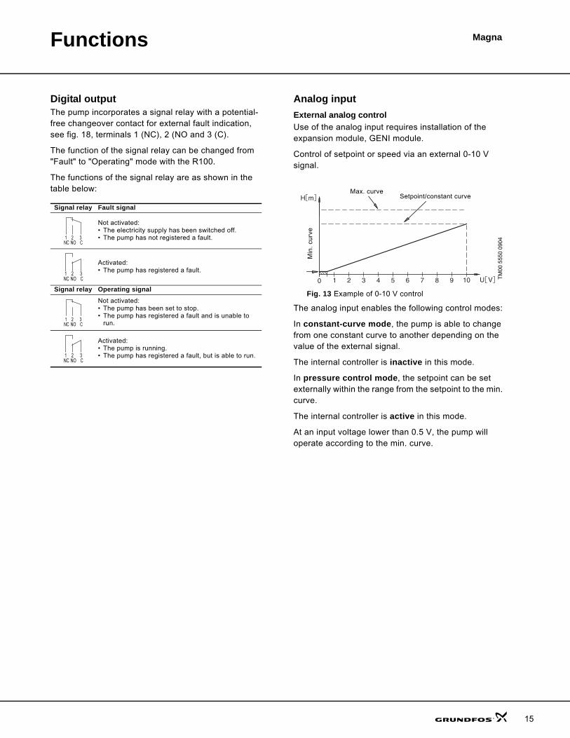
Digital outputThe pump incorporates a signal relay with a potential-free changeover contact for external fault indication, see fig. 18, terminals 1 (NC), 2 (NO and 3 (C).
The function of the signal relay can be changed from "Fault" to "Operating" mode with the R100.
The functions of the signal relay are as shown in the table below:
Analog inputExternal analog control Use of the analog input requires installation of the expansion module, GENI module.
Control of setpoint or speed via an external 0-10 V signal.
Fig. 13 Example of 0-10 V control
The analog input enables the following control modes:
In constant-curve mode, the pump is able to change from one constant curve to another depending on the value of the external signal.
The internal controller is inactive in this mode.
In pressure control mode, the setpoint can be set externally within the range from the setpoint to the min. curve.
The internal controller is active in this mode.
At an input voltage lower than 0.5 V, the pump will operate according to the min. curve.
Signal relay Fault signal
Not activated:• The electricity supply has been switched off.• The pump has not registered a fault.
Activated:• The pump has registered a fault.
Signal relay Operating signal
Not activated:• The pump has been set to stop.• The pump has registered a fault and is unable to
run.
Activated:• The pump is running.• The pump has registered a fault, but is able to run.
1 32NC NO C1 32
NC NO C
1 2 3NC NO C
1 32NC NO C1 32
NC NO C
1 2 3NC NO C
TM
00 5
550
0904
8 9 107654321
m
V
H
U0
Min
. cu
rve
Setpoint/constant curveMax. curve
15
Functions Magna
16
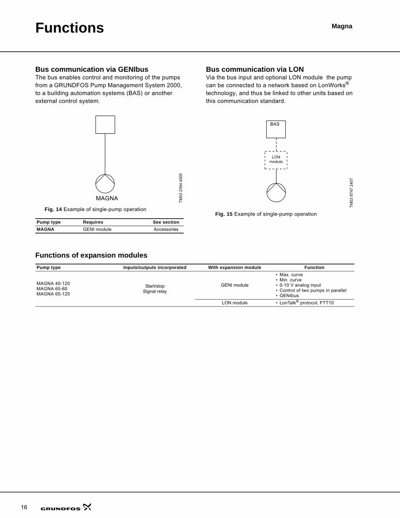
Bus communication via GENIbusThe bus enables control and monitoring of the pumps from a GRUNDFOS Pump Management System 2000, to a building automation systems (BAS) or another external control system.
Fig. 14 Example of single-pump operation
Bus communication via LONVia the bus input and optional LON module the pump can be connected to a network based on LonWorks® technology, and thus be linked to other units based on this communication standard.
Fig. 15 Example of single-pump operation
Functions of expansion modules
TM
03 2
394
4005
Pump type Requires See section MAGNA GENI module Accessories
MAGNA
TM
03 8
747
2407
BAS
LON module
Pump type Inputs/outputs incorporated With expansion module Function
MAGNA 40-120 MAGNA 65-60MAGNA 65-120
Start/stopSignal relay
GENI module
• Max. curve• Min. curve• 0-10 V analog input• Control of two pumps in parallel• GENIbus
LON module • LonTalk® protocol, FTT10
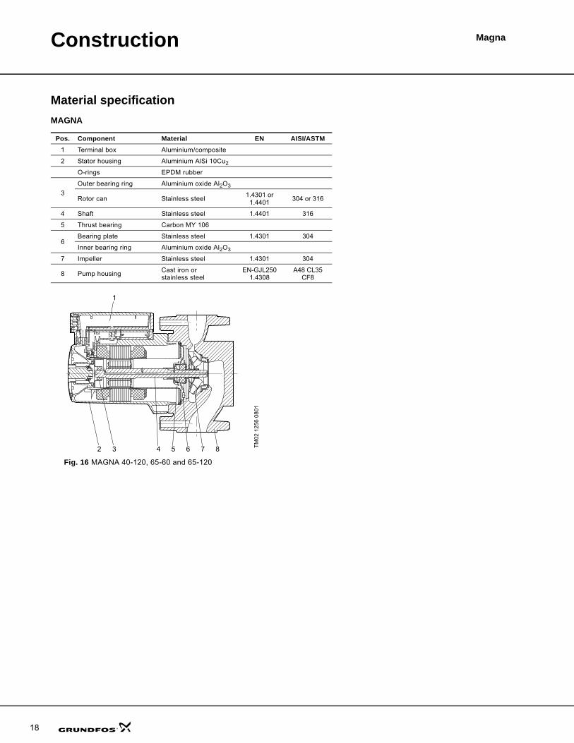
MagnaConstruction
The MAGNA is of the canned-rotor type. The pump and motor form an integral unit without shaft seal and with only two gaskets for sealing. The bearings are lubricated by the pumped liquid.
The pump features are
• controller integrated in the terminal box
• control panel on the terminal box
• terminal box prepared for optional modules
• differential-pressure and temperature detection
• cast-iron or stainless-steel pump housing
• no external motor protection required.
Motor and electronic controllerThe single-phase MAGNA motor is a 4- or 8-pole, synchronous, permanent-magnet motor (PM motor). This motor type has higher efficiency than a conventional asynchronous squirrel-cage motor.
Pump speed is controlled by an integrated frequency converter.
Pump connectionsMAGNA 40-120: Two bolt oval combination flange. Matches GF15/26 and GF 40/43.
MAGNA 65-60 and 65-120: GF53, 4 bolt Non ANSI flange. Can be connected to GF53, 2", 2.5" and , 3" counter flanges.
PaintEnamel paint.Color: Grundfos Red (NCS40-50R)
17
Construction Magna
18
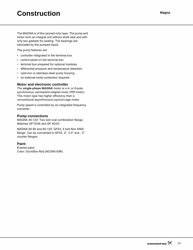
Material specificationMAGNA
Fig. 16 MAGNA 40-120, 65-60 and 65-120
Pos. Component Material EN AISI/ASTM1 Terminal box Aluminium/composite
2 Stator housing Aluminium AlSi 10Cu2
O-rings EPDM rubber
3Outer bearing ring Aluminium oxide Al2O3
Rotor can Stainless steel 1.4301 or1.4401 304 or 316
4 Shaft Stainless steel 1.4401 316
5 Thrust bearing Carbon MY 106
6Bearing plate Stainless steel 1.4301 304
Inner bearing ring Aluminium oxide Al2O3
7 Impeller Stainless steel 1.4301 304
8 Pump housing Cast iron or stainless steel
EN-GJL2501.4308
A48 CL35CF8
TM
02 1
256
0801
765432 8
1

MagnaInstallation
Mechanical installationMAGNA is for indoor installation. The pump shaft shall be installed horizontally.
MAGNA may be installed in horizontal as well as vertical pipes as long as the pump shaft is parallel to the ground. Pump shaft shall not be installed vertically.
Arrows on the pump housing indicate the liquid flow direction through the pump. The liquid flow direction can be horizontal or vertical, depending on the terminal box position.
The terminal box can be turned to various positions. This is described in the installation and operating instructions.
The pump must be installed in such a way that strain from the pipework is not transferred to the pump housing.
The pump may be suspended direct in the pipes, provided the pipework can support the pump. If not, the pump must be installed on a mounting bracket or base plate.
To ensure cooling of motor and electronics, the following must be observed:
• Place the pump in such a way that sufficient cooling is ensured.
• The temperature of the cooling air must not exceed 140°F (40°C.)
19
Installation Magna
20
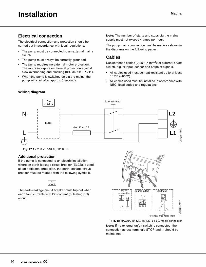
Electrical connectionThe electrical connection and protection should be carried out in accordance with local regulations.
• The pump must be connected to an external mains switch.
• The pump must always be correctly grounded.
• The pump requires no external motor protection. The motor incorporates thermal protection against slow overloading and blocking (IEC 34-11: TP 211).
• When the pump is switched on via the mains, the pump will start after approx. 5 seconds.
Note: The number of starts and stops via the mains supply must not exceed 4 times per hour.
The pump mains connection must be made as shown in the diagrams on the following pages.
CablesUse screened cables (0.25-1.5 mm2) for external on/off switch, digital input, sensor and setpoint signals.
• All cables used must be heat-resistant up to at least 185°F (+85°C).
• All cables used must be installed in accordance with NEC, local codes and regulations.
Wiring diagram
Fig. 17 1 x 230 V +/-10 %, 50/60 Hz
Additional protectionIf the pump is connected to an electric installation where an earth-leakage circuit breaker (ELCB) is used as an additional protection, the earth-leakage circuit breaker must be marked with the following symbols.
The earth-leakage circuit breaker must trip out when earth fault currents with DC content (pulsating DC) occur.
Fig. 18 MAGNA 40-120, 65-120, 65-60, mains connection
Note: If no external on/off switch is connected, the connection across terminals STOP and should be maintained.
TM
03 2
397
4005
External switch
Max. 10 A/16 A
ELCB
L2
L1
TM
02 0
235
1007S
TOP
78
NC NO C
21 3
NL
Mains connection
Signal output Start/stop
Potential-free relay input

Installation Magna
Two pumps in parallel
Two pumps plumbed in parallel can communicate each other with the help of optional GENI module. The modules has to be connected to each other with a wire.
Wiring diagrams: • Master pump, see fig. 19.
• Slave pump, see fig. 20.
Operating modes:Alternating operationPump operation alternates every 24 hours. If the duty pump stops due to a fault, the other pump will start.
Standby operationOne pump is operating continuously. In order to prevent seizing-up, the other pump will start at a fixed frequency and run for a short period. If the duty pump stops due to a fault, the other pump will start.
Fig. 19 Two pumps in parallel, master
Fig. 20 Two pumps in parallel, slave
TM
02 0
480
1004
Max. ø7
CNONCNLOP
TS
A Y B X Q ZMIN
MA
X10
V
2322211211109765478321
Max
. O
D:
0.27
5 in
che s
(7 m
m)
TM
02 0
481
1004
Max. ø7
CNONCNLOP
TS
A Y B X Q ZMIN
MA
X10
V
2322211211109765478321
Max
. O
D:
0.27
5 in
ches
(7 m
m)
21
Installation Magna
22
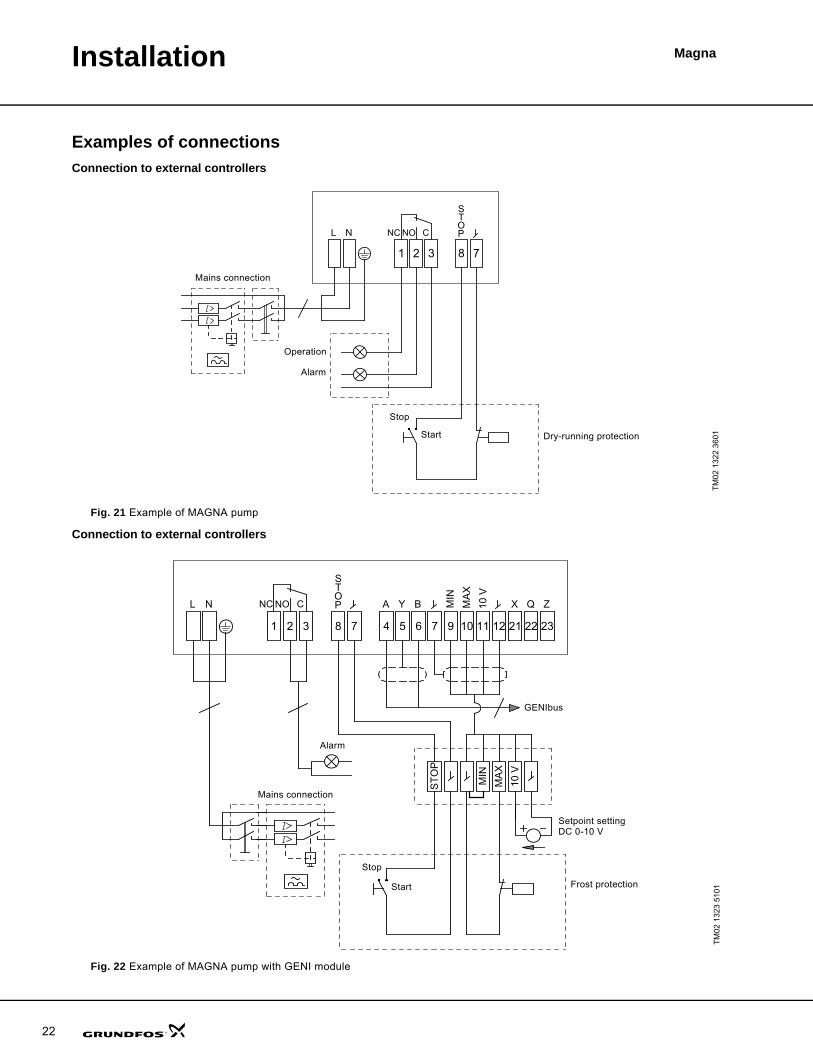
Examples of connectionsConnection to external controllers
Fig. 21 Example of MAGNA pump
Connection to external controllers
Fig. 22 Example of MAGNA pump with GENI module
TM
02 1
322
3601
NC NO C
STOPL N
321 8 7
Mains connection
Alarm
Operation
Stop
Start Dry-running protection
TM
02 1
323
5101
STOP X Q ZBYA M
INM
AX
10 V
NC NO CL N
10 V
MA
XM
IN
1 2 3 8 7 4 5 6 7 9 10 11 12 21 22 23
STO
P
Start
Stop
Mains connection
Alarm
GENIbus
Frost protection
Setpoint setting DC 0-10 V
Magna
23
Curve conditions
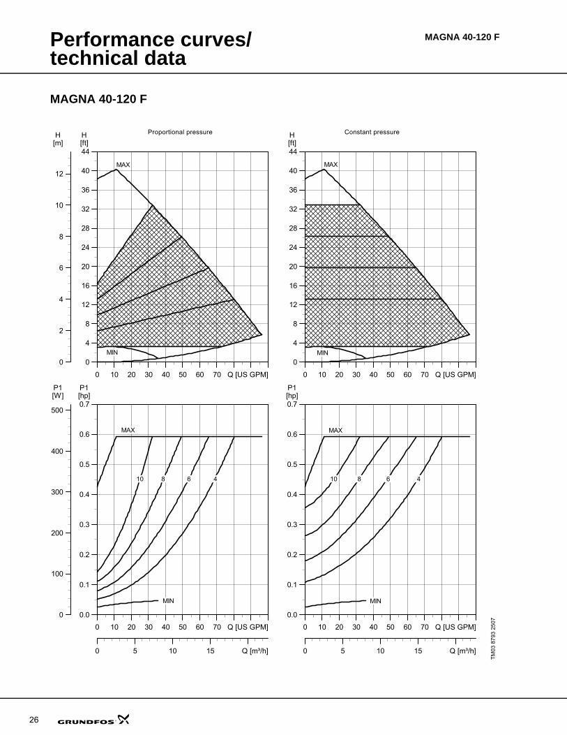
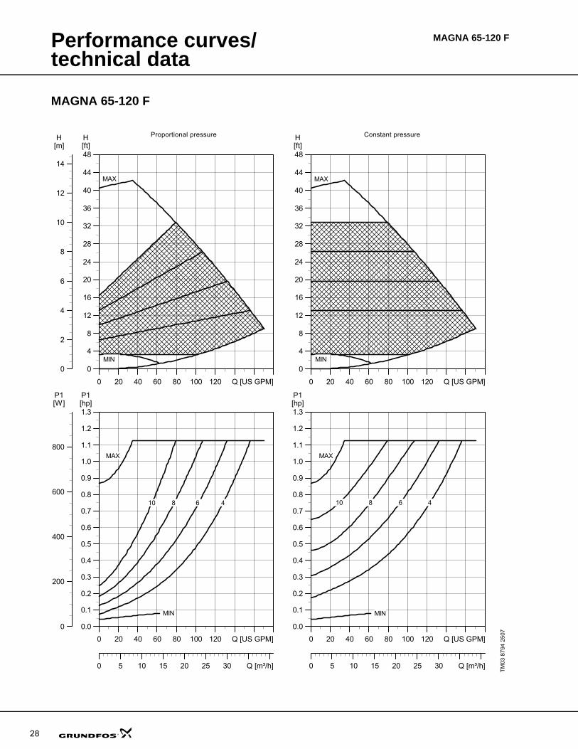
Curve conditionsThe guidelines below apply to the performance curves on pages 23 to 50:
• The bold parts of the curves show the recommended performance range.
• Test liquid: Airless water.
• All curves show average values and should not be used as guarantee curves. If a stated minimum performance is required, individual measurements must be made.
• MAGNA has been tested at 140°F (60°C.)The conversion between head H [ft] and pressure [psi] has been made for water at 140°F (60°C) SG= 0.983. For liquids with other specific gravities, e.g. hot water, the discharge pressure is propor-tional to the specific gravities.
The pumps should not be used at a minimum flow rate lying outside the areas indicated by the bold-faced curves due to danger of pump overheating.
Note: Within MAGNA's performance range, the constant- and proportional-pressure curves can be set in steps of 3.3 ft (1 m) head on the control panel and 0.33 ft (0.1 m) head with the R100.

24
Performance curves/technical data
MAGNA 65-60 F
TM
03 8
792
2507
0 20 40 60 80 100 Q [US GPM]
0
2
4
6
8
10
12
14
16
18
20[ft]H
0
1
2
3
4
5
6[m]H
MAX
MIN
0 20 40 60 80 100 Q [US GPM]
0.0
0.1
0.2
0.3
0.4
0.5
0.6
0.7[hp]P1
0
100
200
300
400
500
[W]P1
0 5 10 15 20 25 Q [m³/h]
MAX
MIN
2 3 4 5
0 20 40 60 80 100 Q [US GPM]
0
2
4
6
8
10
12
14
16
18
20[ft]H
MAX
MIN
0 20 40 60 80 100 Q [US GPM]
0.0
0.1
0.2
0.3
0.4
0.5
0.6
0.7[hp]P1
0 5 10 15 20 25 Q [m³/h]
MAX
MIN
2 3 5 4
Proportional pressure Constant pressure
MAGNA 65-60 F
Performance curves/technical data
MAGNA 65-60 F
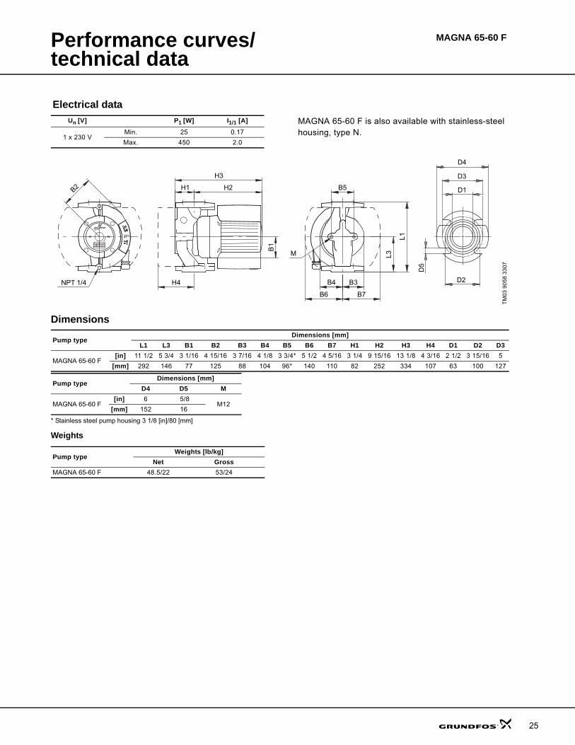
Dimensions
* Stainless steel pump housing 3 1/8 [in]/80 [mm]
Weights
Electrical dataUn [V] P1 [W] I1/1 [A] MAGNA 65-60 F is also available with stainless-steel
housing, type N.1 x 230 V
Min. 25 0.17
Max. 450 2.0
TM
03 9
058
3307
D5
D4
D3
D1
D2NPT 1/4
B2 H2H1
H3
B1
H4
L1
B5
B6 B7
M
B4 B3
L3
Pump typeDimensions [mm]
L1 L3 B1 B2 B3 B4 B5 B6 B7 H1 H2 H3 H4 D1 D2 D3
MAGNA 65-60 F[in] 11 1/2 5 3/4 3 1/16 4 15/16 3 7/16 4 1/8 3 3/4* 5 1/2 4 5/16 3 1/4 9 15/16 13 1/8 4 3/16 2 1/2 3 15/16 5
[mm] 292 146 77 125 88 104 96* 140 110 82 252 334 107 63 100 127
Pump typeDimensions [mm]
D4 D5 M
MAGNA 65-60 F[in] 6 5/8
M12[mm] 152 16
Pump typeWeights [lb/kg]
Net GrossMAGNA 65-60 F 48.5/22 53/24
25
Performance curves/technical data
26
MAGNA 40-120 F
MAGNA 40-120 F
TM
03 8
793
2507
0 10 20 30 40 50 60 70 Q [US GPM]
0
4
8
12
16
20
24
28
32
36
40
44[ft]H
0
2
4
6
8
10
12
[m]H
MAX
MIN
0 10 20 30 40 50 60 70 Q [US GPM]
0.0
0.1
0.2
0.3
0.4
0.5
0.6
0.7[hp]P1
0
100
200
300
400
500
[W]P1
0 5 10 15 Q [m³/h]
MAX
MIN
4 6 8 10
0 10 20 30 40 50 60 70 Q [US GPM]
0
4
8
12
16
20
24
28
32
36
40
44[ft]H
MAX
MIN
0 10 20 30 40 50 60 70 Q [US GPM]
0.0
0.1
0.2
0.3
0.4
0.5
0.6
0.7[hp]P1
0 5 10 15 Q [m³/h]
MAX
MIN
4 6 10 8
Proportional pressure Constant pressure

Performance curves/technical data
MAGNA 40-120 F
Dimensions and weights
* Stainless steel pump housing 3 1/8 [in]/80 [mm]
Weights
Electrical dataUn [V] P1 [W] I1/1 [A] MAGNA 40-120 F is also available with stainless-steel
housing, type N.1 x 230 V
Min. 25 0.17
Max. 450 2.0
TM
03 9
055
3207
D6
D2
D3
D7
D1
D4
D5
Rp 1/4
B2 H2H1
H3
B1
H4
L1
B5
B6 B7
M
B4 B3
L3
NPT
Pump typeDimensions [mm]
L1 L3 B1 B2 B3 B4 B5 B6 B7 H1 H2 H3 H4 D1 D2 D3
MAGNA 40-120 F[in] 8 1/2 4 1/4 3 1/16 4 1/2 2 15/16 3 1/8 3 3/4* 5 1/2 4 5/16 2 11/16 9 1/2 12 3/16 3 3/4 1 9/16 2 15/16 3 1/8 or
3 7/16
[mm] 216 108 77 115 75 80 96* 140 110 68 242 310 96 40 75 80 or 87
Pump typeDimensions [mm]
D4 D5 D6 D7 M
MAGNA 40-120 F[in] 4 3/4 1/2 1 15/16 2 3/8
M12[mm] 120 12 49 60
Pump typeWeights [lb/kg]
Net GrossMAGNA 40-120 F 34/15.5 38/17.5
27
Performance curves/technical data
28
MAGNA 65-120 F
MAGNA 65-120 F
TM
03 8
794
2507
0 20 40 60 80 100 120 Q [US GPM]
0
4
8
12
16
20
24
28
32
36
40
44
48[ft]H
0
2
4
6
8
10
12
14
[m]H
MAX
MIN
0 20 40 60 80 100 120 Q [US GPM]
0.0
0.1
0.2
0.3
0.4
0.5
0.6
0.7
0.8
0.9
1.0
1.1
1.2
1.3[hp]P1
0
200
400
600
800
[W]P1
0 5 10 15 20 25 30 Q [m³/h]
4 6 8 10
MAX
MIN
0 20 40 60 80 100 120 Q [US GPM]
0
4
8
12
16
20
24
28
32
36
40
44
48[ft]H
MAX
MIN
0 20 40 60 80 100 120 Q [US GPM]
0.0
0.1
0.2
0.3
0.4
0.5
0.6
0.7
0.8
0.9
1.0
1.1
1.2
1.3[hp]P1
0 5 10 15 20 25 30 Q [m³/h]
MAX
MIN
10 8 6 4
Proportional pressure Constant pressure
Performance curves/technical data
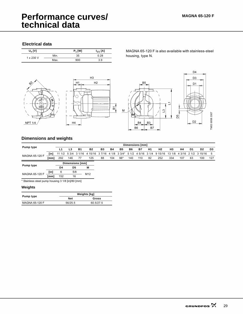
MAGNA 65-120 F
Dimensions and weights
* Stainless steel pump housing 3 1/8 [in]/80 [mm]
Weights
Electrical dataUn [V] P1 [W] I1/1 [A] MAGNA 65-120 F is also available with stainless-steel
housing, type N.1 x 230 V
Min. 35 0.28
Max. 900 3.9
TM
03 9
058
3307
D5
D4
D3
D1
D2NPT 1/4
B2 H2H1
H3
B1
H4
L1
B5
B6 B7
M
B4 B3
L3
Pump typeDimensions [mm]
L1 L3 B1 B2 B3 B4 B5 B6 B7 H1 H2 H3 H4 D1 D2 D3
MAGNA 65-120 F[in] 11 1/2 5 3/4 3 1/16 4 15/16 3 7/16 4 1/8 3 3/4* 5 1/2 4 5/16 3 1/4 9 15/16 13 1/8 4 3/16 2 1/2 3 15/16 5
[mm] 292 146 77 125 88 104 96* 140 110 82 252 334 107 63 100 127
Pump typeDimensions [mm]
D4 D5 M
MAGNA 65-120 F[in] 6 5/8
M12[mm] 152 16
Pump typeWeights [kg]
Net GrossMAGNA 65-120 F 56/25.5 60.5/27.5
29
30
MagnaAccessories
Packaged fitting sets
Flange sets include: 2 each - flanges, gaskets, bolts with nuts.
Use bronze counter flange for stainless steel MAGNA
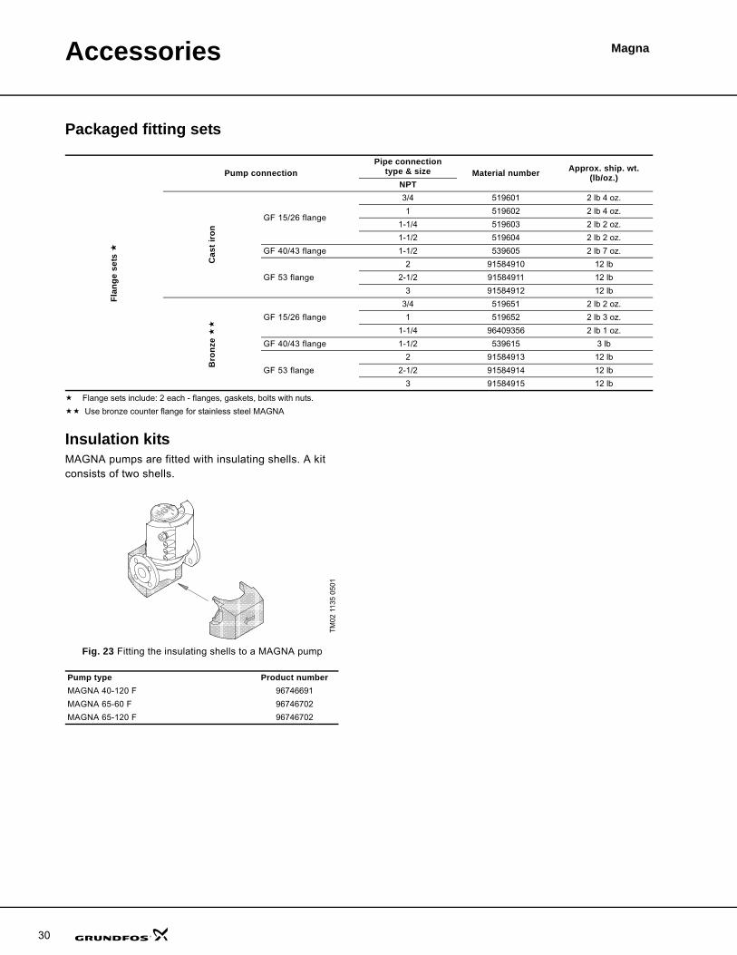
Insulation kitsMAGNA pumps are fitted with insulating shells. A kit consists of two shells.
Fig. 23 Fitting the insulating shells to a MAGNA pump
Flan
ge s
ets
Pump connectionPipe connection
type & size Material number Approx. ship. wt. (lb/oz.)
NPT
Cas
t iro
nGF 15/26 flange
3/4 519601 2 lb 4 oz.
1 519602 2 lb 4 oz.
1-1/4 519603 2 lb 2 oz.
1-1/2 519604 2 lb 2 oz.
GF 40/43 flange 1-1/2 539605 2 lb 7 oz.
GF 53 flange
2 91584910 12 lb
2-1/2 91584911 12 lb
3 91584912 12 lb
Bro
nze
GF 15/26 flange
3/4 519651 2 lb 2 oz.
1 519652 2 lb 3 oz.
1-1/4 96409356 2 lb 1 oz.
GF 40/43 flange 1-1/2 539615 3 lb
GF 53 flange
2 91584913 12 lb
2-1/2 91584914 12 lb
3 91584915 12 lb
TM
02 1
135
0501
Pump type Product numberMAGNA 40-120 F 96746691
MAGNA 65-60 F 96746702
MAGNA 65-120 F 96746702

Accessories Magna
Expansion modules for MAGNAMAGNA pumps can be fitted with an optional expansion module enabling communication via external signals (signal transmitters).
Two types of expansion module are available:
• GENI module
• LON module.
The expansion module is fitted by opening the terminal box cover and placing the module inside the terminal box.
GENI moduleThe GENI module has an input for an external 0-10 VDC analog signal transmitter (terminal 10 V and ). Via this input, the pump can be controlled by an external controller if the pump has been set to one of the following control modes:
• Constant curve
• Proportional- or constant-pressure control.
The GENI module also incorporates inputs for external signals for the forced-control functions:
• Max. curve duty
• Min. curve duty.
Fig. 24 Connection of GENI module
Product Product number GENI module 605945
LON module 605809
Input signals
Setpoint signals
• Max. and min. curve inputExternal potential-free switch.Maximum contact load: 5 V, 1 mA.Screened cable.Maximum loop resistance: 130 Ω.
• Input for analog 0-10 V signalExternal signal: 0-10 VDC.Maximum load: 0.1 mA.Screened cable.
Bus input
Grundfos GENIbus protocol, RS-485.Screened cable.Lead cross section: 0.25 - 1 mm2.Maximum cable length: 3940 ft (1200 m).
TM
02 0
236
1007
4X Q ZBYA M
INM
AX10
V
5 6 7 9 10 1112 2122 23
31
Accessories Magna
32
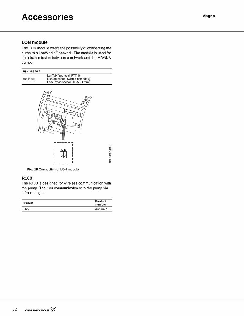
LON moduleThe LON module offers the possibility of connecting the pump to a LonWorks® network. The module is used for data transmission between a network and the MAGNA pump.
Fig. 25 Connection of LON module
R100The R100 is designed for wireless communication with the pump. The 100 communicates with the pump via infra-red light.
Input signals
Bus inputLonTalk®protocol, FTT 10.Non-screened, twisted-pair cable.Lead cross section: 0.25 - 1 mm2.
TM
02 0
237
0904
Product Product number
R100 96615297
BA

Magna
33
Order data
MAGNA, cast iron
MAGNA, stainless steel
Pump typePipe connection
Product numberFlange connection
1.5" 2.5" GF 15/40 GF 53MAGNA 65-60 F X – 96734634
MAGNA 40-120 F X 96734489 –
MAGNA 65-120 F X – 96734640
Pump typePipe connection
Product numberFlange connection
1.5" 2.5" GF 15/40 GF 53MAGNA 65-60 FN X – 96734637
MAGNA 40-120 FN X 96734633 –
MAGNA 65-120 FN X – 96734642

34
MagnaFurther product documentation
WebCAPSWebCAPS is a Web-based Computer Aided Product Selection program available on www.grundfos.com.
WebCAPS contains detailed information on more than 185,000 Grundfos products in more than 22 languages.
In WebCAPS, all information is divided into 6 sections:
• Catalogue
• Literature
• Service
• Sizing
• Replacement
• CAD drawings.
Catalogue
This section is based on fields of application and pump types, and contains • technical data• curves (QH, Eta, P1, P2, etc) which can be adapted to the den-
sity and viscosity of the pumped liquid and show the number of pumps in operation
• product photos• dimensional drawings• wiring diagrams• quotation texts, etc.
Literature
In this section you can access all the latest documents of a given pump, such as• data booklets• installation and operating instructions• service documentation, such as Service kit catalogue and
Service kit instructions• quick guides• product brochures, etc.
Service
This section contains an easy-to-use interactive service catalogue. Here you can find and identify service parts of both existing and dis-continued Grundfos pumps.Furthermore, this section contains service videos showing you how to replace service parts.

Further product documentation
Magna
WinCAPS
Fig. 26 WinCAPS CD-ROM
WinCAPS is a Windows-based Computer Aided Product Selection program containing detailed informa-tion on more than 185,000 Grundfos products in more than 22 languages.
The program contains the same features and functions as WebCAPS, but is an ideal solution if no Internet connection is available.
WinCAPS is available on CD-ROM and updated once a year.
Sizing
This section is based on different fields of application and installa-tion examples, and gives easy step-by-step instructions in how to• select the most suitable and efficient pump for your installation• carry out advanced calculations based on energy consumption,
payback periods, load profiles, life cycle costs, etc.• analyse your selected pump via the built-in life cycle cost tool• determine the flow velocity in wastewater applications, etc.
Replacement
In this section you find a guide to selecting and comparing replace-ment data of an installed pump in order to replace the pump with a more efficient Grundfos pump. The section contains replacement data of a wide range of pumps produced by other manufacturers than Grundfos.
Based on an easy step-by-step guide, you can compare Grundfos pumps with the one you have installed on your site. When you have specified the installed pump, the guide will suggest a number of Grundfos pumps which can improve both comfort and efficiency.
CAD drawings
In this section it is possible to download 2-dimensional (2D) and 3-dimensional (3D) CAD drawings of most Grundfos pumps.
These formats are available in WebCAPS:
2-dimensional drawings:• .dxf, wireframe drawings• .dwg, wireframe drawings.
3-dimensional drawings:• .dwg, wireframe drawings (without surfaces)• .stp, solid drawings (with surfaces)• .eprt, E-drawings.
0 1
35

GRUNDFOS Pumps Corporation 17100 West 118th TerraceOlathe, Kansas 66061Phone: +1-913-227-3400 Telefax: +1-913-227-3500
GRUNDFOS Canada Inc. 2941 Brighton Road Oakville, Ontario L6H 6C9 CanadaPhone: +1-905 829 9533 Telefax: +1-905 829 9512
Bombas GRUNDFOS de Mexico S.A. de C.V. Boulevard TLC No. 15Parque Industrial Stiva AeropuertoApodaca, N.L. Mexico 66600Phone: +52-81-8144 4000 Telefax: +52-81-8144 4010
www.grundfos.com
L-MAG-PG-01 09/07 USSubject to alterations.
Being responsible is our foundationThinking ahead makes it possible
Innovation is the essence