Embed Size (px)
Citation preview
-1-
DocumentazioneTecnica
S19rev. 1.302/2001
© CAMECANCELLI
AUTOMATICI
319S19
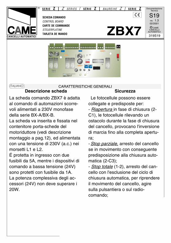
SCHEDA COMANDOCONTROL BOARDCARTE DE COMMANDESTEUERPLATINETARJETA DE MANDO
SERIE Z | Z SERIES / SÉRIE Z | BAUREIHE Z | SERIE Z
ZBX7CANCELLI AUTOMATICI
CARATTERISTICHE GENERALI��������
Descrizione scheda
La scheda comando ZBX7 è adattaal comando di automazioni scorre-voli alimentati a 230V monofasedella serie BX-A/BX-B.La scheda va inserita e fissata nelcontenitore porta-schede delmotoriduttore (vedi descrizionemontaggio a pag.12), ed alimentatacon una tensione di 230V (a.c.) neimorsetti L1 e L2.É protetta in ingresso con duefusibili da 5A, mentre i dispositivi dicomando a bassa tensione (24V)sono protetti con fusibile da 1A.La potenza complessiva degli ac-cessori (24V) non deve superare i20W.
� � � � � � � � �
� � � � � �
����� ��������
��
� � � �
� � � � � � � � � � �
�� ���� � � � � � �
� �
� � � � � �� � � �
Sicurezza
Le fotocellule possono esserecollegate e predisposte per:- Riapertura in fase di chiusura (2-C1), le fotocellule rilevando unostacolo durante la fase di chiusuradel cancello, provocano l'inversionedi marcia fino alla completa apertu-ra;- Stop parziale, arresto del cancellose in movimento con conseguentepredisposizione alla chiusura auto-matica (2-C3);- Stop totale (1-2), arresto del can-cello con l'esclusione del ciclo dichiusura automatica, per riprendereil movimento del cancello, agiresulla pulsantiera o sul radio-comando;
-2-
Nota: Se un contatto di sicurezzanormalmente chiuso (2-C1, 2-C3, 1-2) si apre, viene segnalato dallampeggio del LED di segnalazione(pag.14 - n°10);- Rilevazione di presenza ostacolo.A motore fermo (cancello chiuso,aperto o dopo un comando di stoptotale), impedisce qualsiasi movi-mento se i dispositivi di sicurezza(es.fotocellule) rilevano un ostacolo;
Accessori collegabili
- Lettore ottico art.001B4336, rilevagli ostacoli durante i movimenti delcancello, nella fase di apertura ilcancello si ferma e riprende il movi-mento di chiusura dopo il conteggiodella chiusura automatica, mentre inchiusura inverte il senso di marcia.Attenzione! Nella fase di chiusura,dopo tre rilevamenti consecutivi, ilcancello si ferma in apertura e vieneesclusa la chiusura automatica, perriprendere il movimento del cancel-lo, agire sulla pulsantiera o sulradiocomando.- Lampada ciclo. Lampada cheillumina la zona di manovra, rimaneaccesa dal momento in cui le anteiniziano l’apertura fino alla completachiusura (compreso il tempo dichiusura automatica). Nel caso non
viene inserita la chiusura automati-ca, rimane accesa solo durante ilmovimento.La funzione della lampada ciclo siottiene in uscita W-E1 solo se i dipn°1 «chiusura automatica» e n°6«rilevazione presenza ostacolo»sono posizionati in ON, vedi pagina16.
Altre funzioni
- Chiusura automatica. Iltemporizzatore di chiusura automati-ca si autoalimenta a finecorsa inapertura. Il tempo prefissatoregolabile, è in ogni modo subordi-nato dall'intervento di eventualiaccessori di sicurezza e si escludedopo un intervento di "stop" o inmancanza d'energia elettrica.- Apertura parziale. Apertura delcancello per passaggio pedonale,viene attivata collegandosi aimorsetti 2-3P ed è regolabile me-diante trimmer AP.PARZ.. Conquesta funzione, la chiusura auto-
-3-
matica varia nel seguente modo:1) Dip 1 in ON «chiusura automaticaattivata».- Dopo un'apertura parziale, il tempodi chiusura è dipendente dallaregolazione del trimmer TCA.2) Dip 1 in OFF «chiusura automaticadisattivata».- Se il trimmer del TCA è regolato alminimo, dopo un'apertura parzialenon parte il conteggio di chiusura au-tomatica.;- Se il trimmer del TCA è regolato almassimo, dopo un'apertura parziale,il tempo di chiusura è fisso a 8 secon-di.- "Uomo presente". Funzionamento delcancello mantenendo premuto il pul-sante (esclude la funzione delradiocomando);- Rallentamento a finecorsa.
FUNZIONE DISPONIBILE SOLO PER
CANCELLI CON PESO MASSIMO DI 300KG, ALTRIMENTI DEVE ESSERE
DISATTIVATA
Il cancello rallenta la corsa primadella completa apertura o chiusura.Funziona solo con lettore otticoinserito.Dopo ogni chiusura e apertura dellosportellino di sicurezza o dopo unripristino della tensione, la funzionedi rallentamento è attiva dal 2°comando in poi.- Prelampeggio. Dopo un comando
di apertura o di chiusura, il lampeg-giatore collegato su W-E1, lampeg-gia per 5 secondi prima di iniziare lamanovra.- Comando di chiusura. Funzione disola chiusura del cancello, condispositivo di comando collegato sulcontatto 2-7, posizionare il dip 1 inON (modulo a 4 vie), vedi pagina22;- Comando di apertura. Funzione disola apertura del cancello, condispositivo collegato sul contatto 2-3P, posizionare il dip 2 in ON (mo-dulo a 4 vie), vedi pagina 22;-Tipo di comando:-apre-stop-chiude-stop con pulsantee/o trasmettitore;-apre-chiude con pulsante e/otrasmettitore;-solo apre per trasmettitore.
Regolazioni
- Tempo chiusura automatica;- Tempo di apertura parziale.
ATTENZIONE : prima di intervenireall'interno dell'apparecchiatura, togliere la
tensione di linea
-4-
GENERAL CHARACTERISTICS�����
Description of control panel
The ZBX7 control board is used as aremote control for BX-A/BX-B series230V single-phase automated slidinggates.The board is introduced and fixed inplace in the gearmotor's circuit boardholder (see assembly description onpage 12), at 230V (a.c.) in terminals L1and L2.The inlet is protected with two 5A fuses,while the low voltage (24V) controldevices are protected with a 1A fuse.The accessorie's total capacity (24V)should not exceed 20W.
Safety
Photocells can be connected to obtain:- Re-opening during closure (2-C1), ifthe photocells identify an obstacle whilethe gate is closing, they will reverse thedirection of movement until the gate iscompletely open;- Partial stop, shutdown of moving gate,with activation of an automatic closingcycle (2-C3);- Total stop (1-2), shutdown of gatemovement without automatic closing; apushbutton or radio remote control mustbe actuated to resume movement).N.B: If an NC safety contact (2-C1, 2-C3, 1-2) is opened, the LED (pag.14-n°10) will flash to indicate this fact;
-Obstacle presence detection. When themotor is stopped (gate is closed, openor half-open after an emercency stopcommand), the transmitter and thecontrol pushbutton will be deactivated ifan obstacle is detected by one of thesafety devices (for example, thephotocells);
Accessories which can be connectedto this unit
- Item. 001B4336 optical reader, detectsobstacles during the gate's movement;during the opening phase, the gatestops and then begins a closingmovement after the automatic closurecount, whilst during closure the directionof movement is inverted.Warning: during closure, if obstacles aredetected three times consecutively, thegate will remain open and automaticclosure will be discontinued. To resumethe gate's movement, use the push-button panel or the remote control;- Cycle lamp. The lamp which lights themanoeuvring zone: it remains lit fromthe moment the doors begin to openuntil they are completely closed(including the time required for theautomatic closure). In case automaticclosure is not enabled, the lamp remainslit only during movement.The function of the cycle lamp isobtained in output W-E1 only if dipswitch numbers: 1 “automatic closing”and No. 6 “detect obstacle presence”are set to ON (see page 16).
-5-
Other functions
- Automatic closing. The automaticclosing timer is automatically activatedat the end of the opening cycle. Thepreset, adjustable automatic closingtime is automatically interrupted by theactivation of any safety system, and isdeactivated after a STOP command orin case of power failure;- Partial opening. Gate opening forpassage on foot is activated byconnecting to the 2-3P terminal blocksand it can be adjusted by the AP.PARZ.trimmer. By using this function,automatic closure varies as follows:1) Dip 1 ON - Automatic closureactivated.-after a partial opening, the closure timedoes depend on any adjustment of theTCA trimmer.2) Dip 1 OFF - Automatic closuredeactivated.- If the TCA trimmer is set to theminimum, after a partial opening,automatic closure counting does notbegin;- If the TCA trimmer is set to themaximum, after a partial opening,closing time is set to 8 seconds.- "Operator present". Gate operates onlywhen the pushbutton is held down (theradio remote control system isdeactivated);- Slowing at the limit switch.
FUNCTION AVAIABLE ONLY FOR GATES
WEIGHING UP TO 300 KG, OTHERWISE ITMUST BE DISACTIVATED
The gate slows down before theopening or closing movement iscompleted.
Only works with the optical reader on.After every opening and closing of thesafety door or after restoring thevoltage, the slowing function is activefrom the 2nd command onwards.- Pre-flashing. After an opening orclosing command, the flasher connectedto the W-E1 flashes for 5 secondsbefore beginning the procedure;- Closing command. Function of closingthe gate only, with a wireless controldevice connected to contact 2-7, set dip1 to ON (4-way module), see page 22;- Opening command. Function ofopening the gate only, with a wirelesscontrol device connected to contact 2-3P, set dip 2 to ON (4-way module), seepage 22;-Type of command:-Open-stop-close-stop by button andtransmitter;-Open-close by button and transmitter;-Open only by transmitter.
Adjiustments
- Automatic closure time;- Partial opening time.
IMPORTANT: Shut off the mains powerbefore servicing the inside of the unit.
-6-
CARACTÉRISTIQUES GÉNÉRALES���� ��
Description armoire de commande
La carte de commande ZBX7 estindiquée pour commander lesautomatismes coulissants alimentés à230V et monophasés de la série BX-A/BX-B.Introduire la carte et la fixer dans leporte-cartes du motoréducteur (voirdescription du montage à la page 12).La carte est alimentée avec une tensionde 230V (c.a.) dans les bornes L1 et L2.Elle est protégée à l'entrée par deuxfusibles de 5A, tandis que les dispositifsde commande à basse tension (24V)sont protégés par un fusible de 1A.La puissance totale des accessoires(24V) ne doit pas dépasser 20W.
Sécurité
Il est possible de brancher desphotocellules et de les programmerpour:-Réouverture en phase de fermeture (2-C1), les cellules photoélectriquesprovoquent l'inversion de marchejusqu'à l'ouverture complète si ellesrelèvent un obstacle durant la phase defermeture du portail;-Stop partiel, arrêt du portail, si enmouvement, et conséquente program-mation pour la fermeture automatique(2-C3);-Stop total (1-2), arrêt du portail etdésactivation d’un éventuel cycle defermeture automatique; pour activer denouveau le mouvement, il faut agir surles boutons-poussoirs ou sur laradiocommande.Remarque: Le voyant de signalisation(pag.14 - n°10) qui clignote indiquequ'un contact de sécurité normalmentfermé (2-C1, 2-C3, 1-2) s'ouvre.
-Détection de présence obstacle. Quandle moteur est arrête (portail fermé,ouvert ou semi-ouvert, cette position estobtenue avec une commande de stoptotal), annule toute fonction del'émetteur ou du bouton-poussoir en casd'obstacle détecté par les dispositifs desécurité (ex. Photocellules);
Accessoires pouvant être branchés
- Lecteur optique art. 001B4336, il relèveles obstacles durant les mouvements duportail; durant la phase d'ouverture, leportail s'arrête et reprend le mouvementde fermeture après le comptage de lafermeture automatique tandis qu'ilinverse le sens de marche durant laphase de fermeture.Attention: durant la phase de fermeture,le portail s'arrête en ouverture et lafermeture automatique est exclue aprèstrois relevés consécutifs. Pour reprendrele mouvement du portail, agir sur letableau de commande ou sur laradiocommande;- Lampe cycle. Ampoule qui illumine lazone de manoeuvre: elle reste allumée àpartir du moment ou les portescommencent l’ouverture jusqu’à lafermeture complète (y compris le tempsde fermeture automatique). Si elle n’estpas insérée la fermeture automatiquereste allumée seulement durant lemouvement.On n’obtient la fonction de la lampecycle à la sortie W-E1 que si lescommutateurs à bascule n°1 «fermetureautomatique» et n°6 «relevé présenceobstacle» sont positionnés sur ON, voirpag.16.
-7-
Autres functions
- Fermeture automatique. Le tempo-risateur de fermeture automatique estautoalimenté à la fin du temps de lacourse en ouverture. Le temps réglableest programmé, cependant, il estsubordonné à l’intervention d’éventuelsaccessoires de sécurité et il est excluaprès une intervention de “stop” ou encas de coupure de courant;- Ouverture partielle. Ouverture de lagrille pour le passage pour piétons, elleest enclenchée en la reliant aux bornes2-3P et est réglable par le trimmerAP.PARZ..Avec cette fonction, la fermetureautomatique varie de la façon suivante:1) Dip 1 sur ON Fermeture automatiqueenclenchée.- Aprés une ouverture partielle, le tempsde fermeture est dépendant du réglagedu trimmer TCA.2) Dip 1 sur OFF Fermetureautomatique désenclenchée.- Si le trimmer du TCA est réglé auminimum, aprés une ouverture partiellele comptage de fermeture automatiquene part pas;- Si le trimmer du TCA est réglé aumaximum, aprés une ouverturepartielle, le temps de fermeture est fixeà 8 sec.- Fonction “homme mort”. Fonction-nement du portail en maintenant appuyéle bouton-poussoir (exclut la fonction dela radiocommande);- Ralentissement en fin de course.
FONCTION DISPONIBLE UNIQUEMENT POUR
PORTAILS AYANT UN POIDS MAXIMUM DE 300KG, SINON ELLE DOIT ETRE DESACTIVEE
Le portail ralentit sa course avantl'ouverture ou la fermeture complète.Ne fonctionne que si le lecteur optiqueest installé.La fonction de ralentissement estactivée à partir de la 2e commande,aprés chaque ouverture et fermeture dela porte de sécurité ou après lerétablissement de la tension.- Pré-clignotement. Après unecommande d'ouverture ou de fermeture,le clignotant branché sur W-E1, clignotependant 5 secondes avant decommencer la manoeuvre;- Commande de fermeture. Fonctionuniquement de fermeture du portail,avec dispositif de commande branchésur le contact 2-7, mettre lecommutateur à bascule 1 sur ON(module à 4 voies), voir page 22;- Commande d'ouverture. Fonctionuniquement d'ouverture du portail, avecdispositif de commande branché sur lecontact 2-3P, mettre le commutateur àbascule 2 sur ON (module à 4 voies),voir page 22;-Type de commande:-ouvre-stop-ferme-stop pour bouton etémetteur;-ouvre-ferme pour bouton et émetteur;-seulement ouverture pour émetteur.
Réglages
- Temps de fermeture automatique;- Temps d'ouverture partielle.
ATTENTION: avant d'intervenir à l'intérieurde l'appareillage, couper la tension de
ligne
-8-
ALLGEMEINE MERKMALE�����
Beschreibung des SteuergerätsDie Steuerplatine ZBX7 eignet sich zurSteuerung der Automatik vonSchiebetoren der Baureihe BX-A undBX-B mit 230V Einphasenversorgung.Die Karte wird in das Kartenhalter-Gehäuse des Getriebemotorseingesetzt und dort befestigt (sieheMontageanleitung auf S.12) und miteiner Spannung von 230V (WS) überdie Klemmen L1 und L2 gespeist.Die Karte ist am Eingang mit 2 5A-Sicherungen geschützt, dieNiederspannungs-Steuervorrichtungen(24V) dagegen sind mit einer 1A-Sicherung geschützt.Die Gesamtleistung der Zubehörteile(24V) darf 20W nicht übersteigen.
SicherheitsvorrichtungenDie Lichtschranken können für folgendeFunktionen angeschlossen bzw.vorbereitet werden:- Wiederöffnen beim Schließen (2-C1),die Lichtschranken ermitteln einHindernis während des schließens vomTor und lösen die Umkehr derLaufrichtung vom Tor aus, bis dieseswieder vollständig geöffnet ist;- Teilstop, Stillstand des Tores währenddes Torlaufs, mit darauffolgenderautomatischer Torschließung (2-C3);- Totalstop (1-2), sofortiger Stillstand desTores mit Ausschluß eventuellerSchließautomatik: Fortsetzung desTorlaufs über Drucktaster- bzw.Funksendersteuerung;Hinweis: Wenn sich ein normalerweisegeschlossener (NC) Sicherheitskontakt(2-C1, 2-C3, 1-2) öffnet, wird dies durchBlinken der Kontrolleuchte (S.14 - n°10)angezeigt;
-Ermittlung eventuell vorhandenerHindernisse. Bei stillstehendem Motor(Tor geschlossen, geöffnet oder durcheine Totalstop-Steuerung halb geöffnet)wird bei durch die Sicherheits-vorrichtungen (z.B.:Lichtschranken)erfaßtem Hindernis jede Sensor-oderDrucktasterfunktion annulliert.
Anschließbares Zubehör- Optischer Leser Art.001B4336,Ermittelt eventuelle Hindernisse,während das Tor in Bewegung ist.Wenn das Hindernis in derÖffnungsphase ermittelt wird, hält dasTor an und schließt sich dann wieder,nachdem die für das automatischeSchließen vorgegebene Zeit abgelaufenist. Wenn das Hindernis dagegen in derSchließphase ermittelt wird, wird einfachdie Laufrichtung vom Tor umgekehrt.Achtung! Wenn in der Schließphasedremal hintereinander ein Hindernisermittelt wird, bleibt das Tor offen unddas automatische Schlißen wirddeaktiviert. Damit das Tor seine norma-le Funktion wieder aufnimmt, einfacheine Taste an der Steuerung oder derFernbedienung drücken;- Betriebszyklus-Anzeigeleuchte. DasLicht, das den Torbereich beleuchtet,bleibt vom Beginn des Öffnens bis zumvollständigen Schließen der Torflügeleingeschaltet (einschließlich Wartezeitfür automatisches Schließen nichtzugeschaltet ist, bleibt das Licht nurwährend der Torbewegungeingeschaltet.Die Funktion der Lampe für den Zykluserhält man nur dann auf dem AusgangW-E1, wenn die Dip-Switches Nr.1“Automatisches Schließen” und Nr.6“Ermittlung von Hindernisen” auf ONstehen (siehe S.16)
-9-
Andere Wahlfunktionen- Schließautomatik. Der Schließautoma-tik-Zeischalter speist sich beim Öffnenam Ende der Torlaufzeit selbst . Dievoreingestellte Zeit ist auf jeden Fallimmer dem Eingriff eventuellerSicherheitsvorrichtungen untergeordnetund schließt sich nach einem “Stop”-Eingriff bzw. bei Stromausfall selbst aus;-Teilweises Öffnung. Das Öffnen desTors für das Durchlassen vonFußgängern wird durch Anschluß an dieKlemmen 2-3P aktiviert und kann überden Trimmer AP.PARZ. eingestelltwerden; Wenn diese Funktion aktiviertist, variiert das automatische Schließenfolgendermaßen.1) Dip 1 auf ON - AutomatischesSchließen aktiviert.- Hach einem teilweisen Öffnen erfolgtdas Schließen des Tor untergebene vonder Einstellung der Trimmer TCA.2) Dip 1 auf OFF - AutomatischesSchließen abgeschaltet.- Wenn der Trimmer TCA auf dasMinimum gestellt ist, läuft das Abzählenfür das automatische Schließen nacheinem teilweisen Öffnen des Tors nichab;- Wenn der Trimmer TCA auf dasMaximum gestellt ist, beträgt dieZeitspanne zwischen einem teilweisenÖffnen und dem automatischenSchließen des Tors 8 Sekunden.- “Bedienung vom Steuerpult”. Torbetriebdurch Drucktasterbetätigung (Funk-fernsteuerung ausgeschlossen);- Abbremsen am Endanschlag.
DIE FUNKTION KANN NUR BEI TOREN MIT EI-NEM GEWICHT VON MAXIMAL 300 KG EINGE-
SETZT WERDEN. BEI SCHWEREREN TOREN
MUSS SIE DEAKTIVIERT WERDEN!
Das Tor bremst seinen Lauf ab, bevores sich komplett öffnet oder schließt.Diese Funktion ist nur dann aktiviert,wenn ein optisches Lesegeräteingesteckt ist.Nach dem Öffnen und Schließen derSicherheitsklappe oder nach einemStromausfall wird die Bremsfunktion abdem zweiten Öffnungs- oderSchließbefehl aktiviert.- Vorblinken. Nachdem der Befehl zumÖffnen oder Schließen gegeben wordenist, blinkt das Blinklicht, das an W-E1angeschlossen ist, zunächst 5Sekunden, bevor das Manöver beginnt;- Schließbefehl. Funktion ausschließlichzum Schließen des Tors. Dazu dieSteuervorrichtung an den Kontakt 2-7anschließen und den Dip-Schalter 1 aufON stellen (4-Weg Modul), Siehe hierzuS.22;- Öffnungsbefehl. Funktionausschließlich zum Öffnen des Tors.Dazu die Steuervorrichtung an denKontakt 2-3P anschließen und den Dip-Schalter 2 auf ON stellen (4-WegModul), Siehe hierzu S.22;-Befehlsarten:-Öffnen-Stop-Schließen-Stop fürDruckknopf und Sender;-Öffnen-Schließen für Druckknopf undSender;-nur Öffnen für Sender.
Einstellungen- Zeit für das automatische Schließen;- Zeit für das teilweise Öffnen.
ACHTUNG: Das Gerät vor Eingriffen iminneren spannungsfrei schalten
-10-
CARACTERISTICAS GENERALES������
Descripciön cuadro de mando
La tarjeta de mando ZBX7 es idóneapara el accionamiento deautomatizaciones de puertas correderasalimentadas a 230V monofásica de laserie BX-A/BX-B.La tarjeta se introduce y fija en la cajarespectiva en el motorreductor (véasedescripción montaje en pág.12), y sealimenta con una tensión de 230V (c.a.)en los bornes L1 y L2.La tarjeta está protegida en la entradapor dos fusibles de 5A, mientras que losdispositivos de accionamiento de bajatensión (24V) están protegidos porfusible de 1A.La potencia total de los accesorios (24V)no tiene que superar los 20W.
Seguridad
Il est possible de brancher desphotocellules et de les programmerpour:- Réouverture en phase de fermeture(2-C1), les cellules photoélectriquesprovoquent l'inversion de marchejusqu'à l'ouverture complète si ellesrelèvent un obstacle durant la phase defermeture du portail;-Parada parcial, parada de la puerta sise encuentra en movimiento con laconsiguiente predisposición al cierreautomático (2-C3);-Parada total (1-2), parada de la puertaexcluyendo el posible ciclo de cierreautomático, para reactivar el movimientoes preciso actuar en el teclado o en elmando a distancia;Nota: La apertura de un contacto deseguridad normalmente cerrado (2-C1,2-C3, 1-2) es señalada por medio del
destello del LED de señalización(pág.14 - n°10).-Detección de presencia obstáculo. Conel motor parado (puerta cerrada, abiertao en posición semi-abierta obtenida através de un comando de stop total),anula cualquier función del transmisor odel botón en caso de obstáculodetectado por los dispositivos deseguridad (por ejemplo: fotocélulas).
Accesorios conectables
- Lector óptico art. 001B4336, detectalos obstáculos durante los movimientosde la puerta; durante la apertura lapuerta se detiene e inicia el movimientode cierre, después de la cuenta delcierre automático; mientras, que duranteel cierre, invierte la dirección delmovimiento.Atención: durante el cierre, tras tresdetecciones consecutivas, la puerta sedetiene en el movimiento de apertura yse desconecta el cierre automático, parareactivar el movimiento de la puerta, useel pulsador o el radiocontrol;- Lámpara ciclo. Lámpara que alumbrala zona de maniobra: se quedaencendida a partir del momento en quelas hojas empiezan la apertura hasta elcierre completo (incluyendo el tiempo decierre automático). Si no se habilita elcierre automático, el cierre permaneceencendido sólo durante el movimiento.El funcionamiento de la lámpara ciclo seobtiene en la salida W-E1 sólo si los dipsn°1 “cierre automático” y n°6 “detecciónpresencia obstáculo” están colocadosen ON, véase página 16.
-11-
Otras funciones
- Cierre automático. El temporizador decierre automático se autoalimenta enfin-de-tiempo carrera en fase de apertu-ra. El tiempo prefijado regulable, sinembargo, está subordinado a laintervención de posibles accesorios deseguridad y se excluye después de unaintervención de parada o en caso defalta de energía eléctrica;- Apertura parcial. La apertura de laverja para el paso peatonal, se activaconectado los bprnes 2-3P y puede serregulada por medio del trimmerAP.PARZ.;Con esta función, el cierre automáticose modifica de la siguiente manera:1) Dip 1 en ON «cierre automáticoactivo».- Tras una apertura parcial, el tiempo decierre es dependiente de la regulacióndel trimmer TCA.2) Dip 1 en OFF «cierre automáticodesactivado».-Si el trimmer del TCA está regulado almínimo, tras una apertura parcial no seacciona la cuenta de cierre automático;- Si el trimmer del TCA está regulado almáximo, tras una apertura parcial, eltiempo de cierre queda fijo en 8".- Función a "hombre presente".Funcionamiento de la puertamanteniendo pulsada la tecla (excluyela función del mando a distancia);- Desaceleración en final de carrera.
FUNCIÓN DISPONIBLE SÓLO PARA CANCELAS
CON 300 KG DE PESO MÁXIMO, EN CASO
CONTRARIO DEBE SER DESACTIVADA
La puerta desacelera la carrera antesde completar la apertura o el cierre.Funciona sólo con lector ópticoconectado.Tras cada apertura o cierre de la tapade seguridad, o tras una reactivación dela tensión, la función de desaceleraciónestá activa desde el 2° mando enadelante.- Intermitencia. Después de un mandode apertura o cierre, la lámparaintermitente conectada en W-E1,parpadea por 5 segundos antes decomenzar la maniobra;- Mando de cierre. Función sólo decierre de la puerta, con dispositivo demando conectado en el contacto 2-7,coloque el dip 1 en ON (módulo de 4vías), véase página 22;- Mando de apertura. Función sólo deapertura de la puerta, con dispositivo demando conectado en el contacto 2-3P,coloque el dip 2 en ON (módulo de 4vías), véase página 22;-Tipo de mando:-abrir-stop-cerrar-stop para botón ytransmisor;-abrir-cerrar para botón y transmisor;-sólo apertura para transmisor.
Regulaciones
- Tiempo de cierre automático;- Tiempo de apertura parcial.
ATENCION: antes de actuar dentro delaparado, quitar la tensión de línea
-12-
DESCRIZIONE DI MONTAGGIO - ASSEMBLY DESCRIPTION - DESCRIPTION DU MONTAGEMONTAGEANLEITUNG - DESCRIPTIÓN DEL MONTAJE
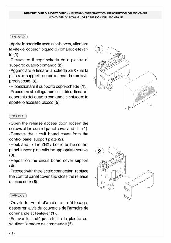
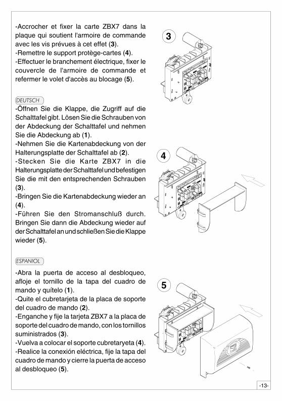
-Aprire lo sportello accesso sblocco, allentarela vite del coperchio quadro comando e levar-lo (1).-Rimuovere il copri-scheda dalla piastra disupporto quadro comando (2).-Agganciare e fissare la scheda ZBX7 nellapiastra di supporto quadro comando con le vitipredisposte (3).-Riposizionare il supporto copri-schede (4).-Procedere al collegamento elettrico, fissare ilcoperchio del quadro comando e chiudere losportello accesso blocco (5).
��������
�����
1
2
-Open the release access door, loosen thescrews of the control panel cover and lift it (1).-Remove the circuit board cover from thecontrol panel support plate (2).-Hook and fix the ZBX7 board to the controlpanel support plate with the appropriate screws(3).-Reposition the circuit board cover support(4).-Proceed with the electric connection, replacethe control panel cover and close the releaseaccess door (5).
���� ��
-Ouvrir le volet d'accès au déblocage,desserrer la vis du couvercle de l'armoire decommande et l'enlever (1).-Enlever le protège-carte de la plaque quisoutient l'armoire de commande (2).
-13-
3
�����
�������
-Öffnen Sie die Klappe, die Zugriff auf dieSchalttafel gibt. Lösen Sie die Schrauben vonder Abdeckung der Schalttafel und nehmenSie die Abdeckung ab (1).-Nehmen Sie die Kartenabdeckung von derHalterungsplatte der Schalttafel ab (2).-Stecken Sie die Karte ZBX7 in dieHalterungsplatte der Schalttafel und befestigenSie die mit den entsprechenden Schrauben(3).-Bringen Sie die Kartenabdeckung wieder an(4).-Führen Sie den Stromanschluß durch.Bringen Sie dann die Abdeckung wieder aufder Schalttafel an und schließen Sie die Klappewieder (5).
-Abra la puerta de acceso al desbloqueo,afloje el tornillo de la tapa del cuadro demando y quítelo (1).-Quite el cubretarjeta de la placa de soportedel cuadro de mando (2).-Enganche y fije la tarjeta ZBX7 a la placa desoporte del cuadro de mando, con los tornillossuministrados (3).-Vuelva a colocar el soporte cubretaryeta (4).-Realice la conexión eléctrica, fije la tapa delcuadro de mando y cierre la puerta de accesoal desbloqueo (5).
4
5
-Accrocher et fixer la carte ZBX7 dans laplaque qui soutient l'armoire de commandeavec les vis prévues à cet effet (3).-Remettre le support protège-cartes (4).-Effectuer le branchement électrique, fixer lecouvercle de l'armoire de commande etrefermer le volet d'accès au blocage (5).
-14-
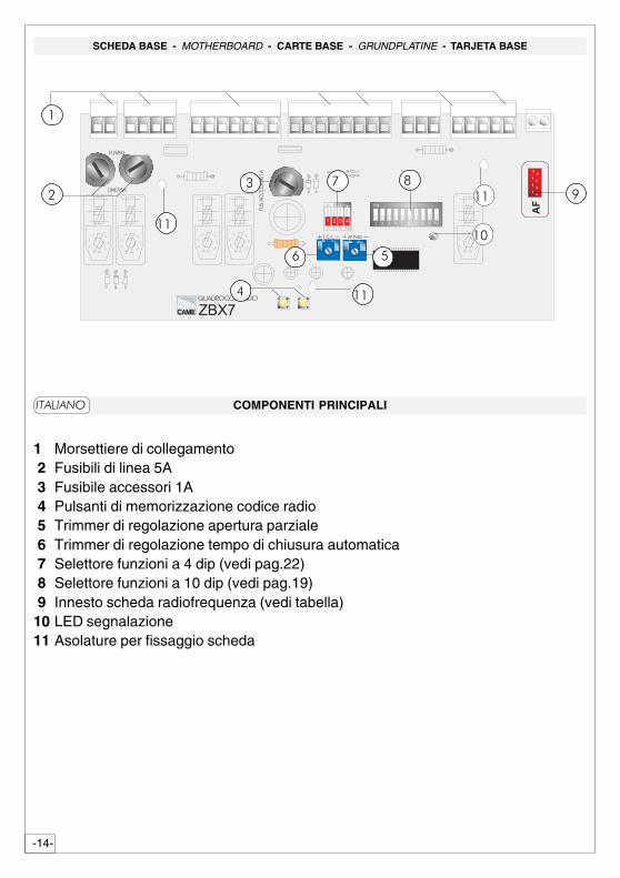
SCHEDA BASE - MOTHERBOARD - CARTE BASE - GRUNDPLATINE - TARJETA BASE
COMPONENTI PRINCIPALI
1 Morsettiere di collegamento 2 Fusibili di linea 5A 3 Fusibile accessori 1A 4 Pulsanti di memorizzazione codice radio 5 Trimmer di regolazione apertura parziale 6 Trimmer di regolazione tempo di chiusura automatica 7 Selettore funzioni a 4 dip (vedi pag.22) 8 Selettore funzioni a 10 dip (vedi pag.19) 9 Innesto scheda radiofrequenza (vedi tabella)10 LED segnalazione11 Asolature per fissaggio scheda
��������
� � � � � � � � �
� � � � � �
����� ��������
��
� � � �
� � � � � � � � � � �
�� ���� � � � � � �
� �
� � � � � �� � � �
�
��
��
�
�
�
�
��
��
��
-15-
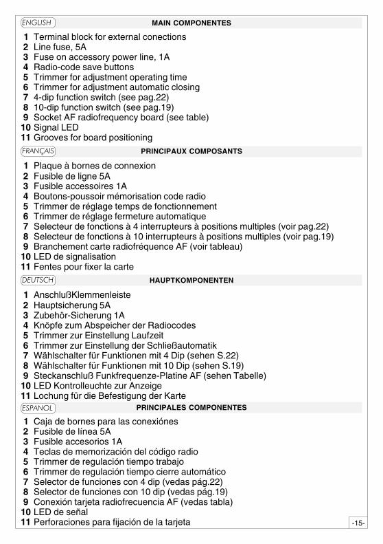
HAUPTKOMPONENTEN
1 AnschlußKlemmenleiste 2 Hauptsicherung 5A 3 Zubehör-Sicherung 1A 4 Knöpfe zum Abspeicher der Radiocodes 5 Trimmer zur Einstellung Laufzeit 6 Trimmer zur Einstellung der Schließautomatik 7 Wählschalter für Funktionen mit 4 Dip (sehen S.22) 8 Wählschalter für Funktionen mit 10 Dip (sehen S.19) 9 Steckanschluß Funkfrequenze-Platine AF (sehen Tabelle)10 LED Kontrolleuchte zur Anzeige11 Lochung für die Befestigung der Karte
PRINCIPALES COMPONENTES
1 Caja de bornes para las conexiónes 2 Fusible de línea 5A 3 Fusible accesorios 1A 4 Teclas de memorización del código radio 5 Trimmer de regulación tiempo trabajo 6 Trimmer de regulación tiempo cierre automático 7 Selector de funciones con 4 dip (vedas pág.22) 8 Selector de funciones con 10 dip (vedas pág.19) 9 Conexión tarjeta radiofrecuencia AF (vedas tabla)10 LED de señal11 Perforaciones para fijación de la tarjeta
MAIN COMPONENTES
�1 Terminal block for external conections 2 Line fuse, 5A 3 Fuse on accessory power line, 1A 4 Radio-code save buttons 5 Trimmer for adjustment operating time 6 Trimmer for adjustment automatic closing 7 4-dip function switch (see pag.22) 8 10-dip function switch (see pag.19) 9 Socket AF radiofrequency board (see table)10 Signal LED11 Grooves for board positioning
�����
�����
������
PRINCIPAUX COMPOSANTS
1 Plaque à bornes de connexion 2 Fusible de ligne 5A 3 Fusible accessoires 1A 4 Boutons-poussoir mémorisation code radio 5 Trimmer de réglage temps de fonctionnement 6 Trimmer de réglage fermeture automatique 7 Selecteur de fonctions à 4 interrupteurs à positions multiples (voir pag.22) 8 Selecteur de fonctions à 10 interrupteurs à positions multiples (voir pag.19) 9 Branchement carte radiofréquence AF (voir tableau)10 LED de signalisation11 Fentes pour fixer la carte
���� ��
-16-
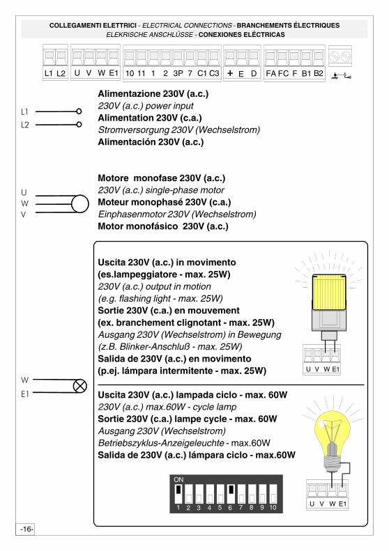
COLLEGAMENTI ELETTRICI - ELECTRICAL CONNECTIONS - BRANCHEMENTS ÉLECTRIQUES ELEKRISCHE ANSCHLÜSSE - CONEXIONES ELÉCTRICAS
�
��
�
�
��
��
Alimentazione 230V (a.c.)230V (a.c.) power inputAlimentation 230V (c.a.)Stromversorgung 230V (Wechselstrom)Alimentación 230V (a.c.)
Motore monofase 230V (a.c.)230V (a.c.) single-phase motorMoteur monophasé 230V (c.a.)Einphasenmotor 230V (Wechselstrom)Motor monofásico 230V (a.c.)
Uscita 230V (a.c.) in movimento(es.lampeggiatore - max. 25W)230V (a.c.) output in motion(e.g. flashing light - max. 25W)Sortie 230V (c.a.) en mouvement(ex. branchement clignotant - max. 25W)Ausgang 230V (Wechselstrom) in Bewegung(z.B. Blinker-Anschluß - max. 25W)Salida de 230V (a.c.) en movimento(p.ej. lámpara intermitente - max. 25W)
Uscita 230V (a.c.) lampada ciclo - max. 60W230V (a.c.) max.60W - cycle lampSortie 230V (c.a.) lampe cycle - max. 60WAusgang 230V (Wechselstrom)Betriebszyklus-Anzeigeleuchte - max.60WSalida de 230V (a.c.) lámpara ciclo - max.60W
10 11 1 2 7 C1L1 L2 U V W E1 3P C3 FA FC F B1 B2E D
U V W E1
U V W E1
21 3 4 5 6 7 8 9 10
ON
-17-
��
��
��
��
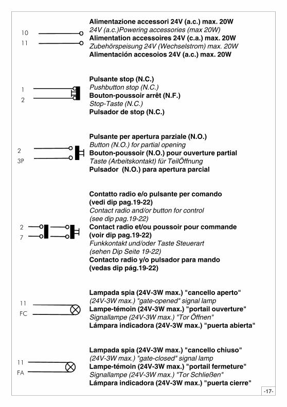
Alimentazione accessori 24V (a.c.) max. 20W24V (a.c.)Powering accessories (max 20W)Alimentation accessoires 24V (c.a.) max. 20WZubehörspeisung 24V (Wechselstrom) max. 20WAlimentación accesoios 24V (a.c.) max. 20W
Pulsante stop (N.C.)Pushbutton stop (N.C.)Bouton-poussoir arrêt (N.F.)Stop-Taste (N.C.)Pulsador de stop (N.C.)
Pulsante per apertura parziale (N.O.)Button (N.O.) for partial openingBouton-poussoir (N.O.) pour ouverture partialTaste (Arbeitskontakt) für TeilÖffnungPulsador (N.O.) para apertura parcial
Contatto radio e/o pulsante per comando(vedi dip pag.19-22)Contact radio and/or button for control(see dip pag.19-22)Contact radio et/ou poussoir pour commande(voir dip pag.19-22)Funkkontakt und/oder Taste Steuerart(sehen Dip Seite 19-22)Contacto radio y/o pulsador para mando(vedas dip pág.19-22)
Lampada spia (24V-3W max.) "cancello aperto"(24V-3W max.) "gate-opened" signal lampLampe-témoin (24V-3W max.) "portail ouverture"Signallampe (24V-3W max.) "Tor Öffnen"Lámpara indicadora (24V-3W max.) "puerta abierta"
Lampada spia (24V-3W max.) "cancello chiuso"(24V-3W max.) "gate-closed" signal lampLampe-témoin (24V-3W max.) "portail fermeture"Signallampe (24V-3W max.) "Tor Schließen"Lámpara indicadora (24V-3W max.) "puerta cierre"
��
��
��
��
��
��
��
��
-18-
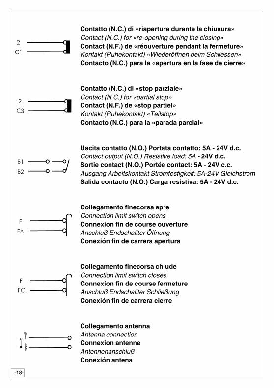
Contatto (N.C.) di «riapertura durante la chiusura»Contact (N.C.) for «re-opening during the closing»Contact (N.F.) de «réouverture pendant la fermeture»Kontakt (Ruhekontakt) «Wiederöffnen beim Schliessen»Contacto (N.C.) para la «apertura en la fase de cierre»
Contatto (N.C.) di «stop parziale»Contact (N.C.) for «partial stop»Contact (N.F.) de «stop partiel»Kontakt (Ruhekontakt) «Teilstop»Contacto (N.C.) para la «parada parcial»
Uscita contatto (N.O.) Portata contatto: 5A - 24V d.c.Contact output (N.O.) Resistive load: 5A - 24V d.c.Sortie contact (N.O.) Portée contact: 5A - 24V c.c.Ausgang Arbeitskontakt Stromfestigkeit: 5A-24V GleichstromSalida contacto (N.O.) Carga resistiva: 5A - 24V d.c.
Collegamento finecorsa apreConnection limit switch opensConnexion fin de course ouvertureAnschluß Endschallter ÖffnungConexión fin de carrera apertura
Collegamento finecorsa chiudeConnection limit switch closesConnexion fin de course fermetureAnschluß Endschallter SchließungConexión fin de carrera cierre
Collegamento antennaAntenna connectionConnexion antenneAntennenanschlußConexión antena
��
��
��
��
��
��
��
�
��
��
-19-
SELEZIONI FUNZIONI - SELECTION OF FUNCTIONS - SÉLECTION FONCTIONSFUNKTIONSWAHL- SELECCIÓN DE LAS FUNCIONES
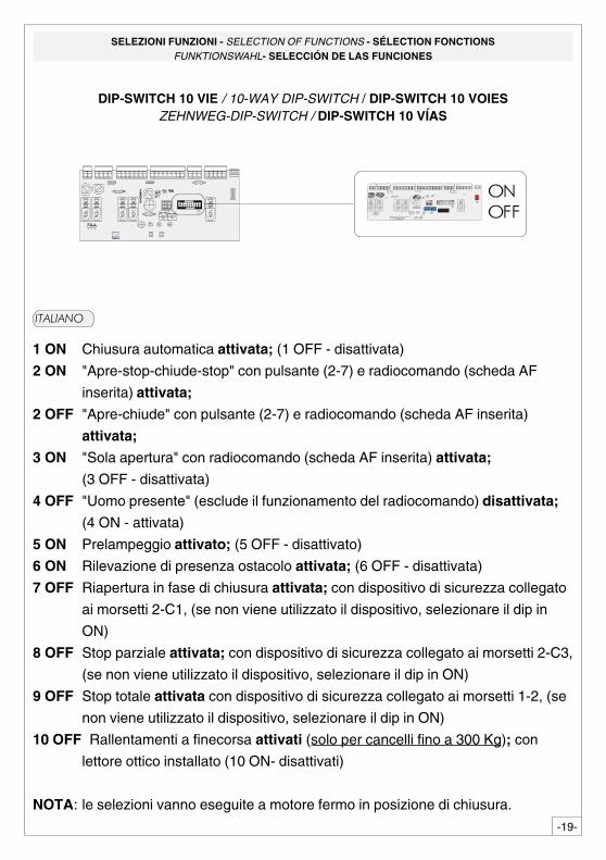
DIP-SWITCH 10 VIE / 10-WAY DIP-SWITCH / DIP-SWITCH 10 VOIESZEHNWEG-DIP-SWITCH / DIP-SWITCH 10 VÍAS
� ����������������
21 3 4 5 6 7 8 9 10
ON
� � � � � � � � �
� � � � � �
����� ���
�����
��
� � � �
� � � � � � � � � � �
�� ���� � � � � � �
� �
� � � � � �� � � �
��������
1 ON Chiusura automatica attivata; (1 OFF - disattivata)
2 ON "Apre-stop-chiude-stop" con pulsante (2-7) e radiocomando (scheda AF
inserita) attivata;
2 OFF "Apre-chiude" con pulsante (2-7) e radiocomando (scheda AF inserita)
attivata;
3 ON "Sola apertura" con radiocomando (scheda AF inserita) attivata;
(3 OFF - disattivata)
4 OFF "Uomo presente" (esclude il funzionamento del radiocomando) disattivata;
(4 ON - attivata)
5 ON Prelampeggio attivato; (5 OFF - disattivato)
6 ON Rilevazione di presenza ostacolo attivata; (6 OFF - disattivata)
7 OFF Riapertura in fase di chiusura attivata; con dispositivo di sicurezza collegato
ai morsetti 2-C1, (se non viene utilizzato il dispositivo, selezionare il dip in
ON)
8 OFF Stop parziale attivata; con dispositivo di sicurezza collegato ai morsetti 2-C3,
(se non viene utilizzato il dispositivo, selezionare il dip in ON)
9 OFF Stop totale attivata con dispositivo di sicurezza collegato ai morsetti 1-2, (se
non viene utilizzato il dispositivo, selezionare il dip in ON)
10 OFF Rallentamenti a finecorsa attivati (solo per cancelli fino a 300 Kg); con
lettore ottico installato (10 ON- disattivati)
NOTA: le selezioni vanno eseguite a motore fermo in posizione di chiusura.
�����
-20-
���� ��
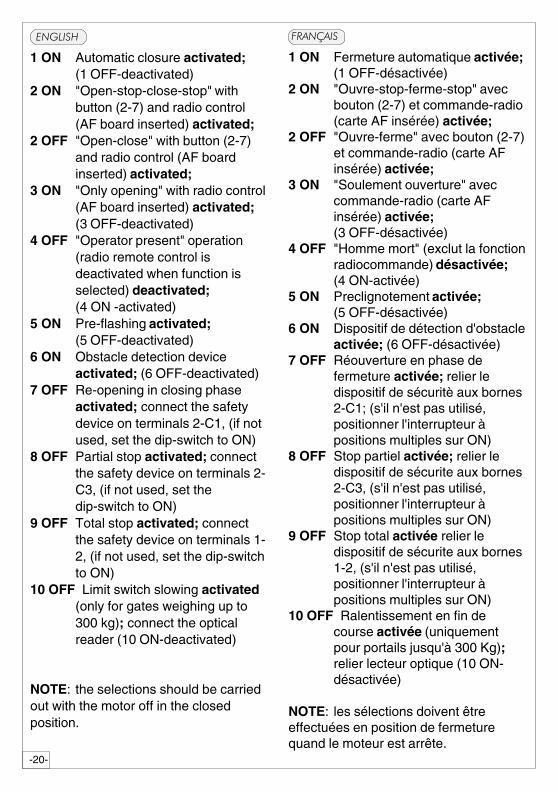
1 ON Fermeture automatique activée;(1 OFF-désactivée)
2 ON "Ouvre-stop-ferme-stop" avecbouton (2-7) et commande-radio(carte AF insérée) activée;
2 OFF "Ouvre-ferme" avec bouton (2-7)et commande-radio (carte AFinsérée) activée;
3 ON "Soulement ouverture" aveccommande-radio (carte AFinsérée) activée;(3 OFF-désactivée)
4 OFF "Homme mort" (exclut la fonctionradiocommande) désactivée;(4 ON-activée)
5 ON Preclignotement activée;(5 OFF-désactivée)
6 ON Dispositif de détection d'obstacleactivée; (6 OFF-désactivée)
7 OFF Réouverture en phase defermeture activée; relier ledispositif de sécuritè aux bornes2-C1; (s'il n'est pas utilisé,positionner l'interrupteur àpositions multiples sur ON)
8 OFF Stop partiel activée; relier ledispositif de sécurite aux bornes2-C3, (s'il n'est pas utilisé,positionner l'interrupteur àpositions multiples sur ON)
9 OFF Stop total activée relier ledispositif de sécurite aux bornes1-2, (s'il n'est pas utilisé,positionner l'interrupteur àpositions multiples sur ON)
10 OFF Ralentissement en fin decourse activée (uniquementpour portails jusqu'à 300 Kg);relier lecteur optique (10 ON-désactivée)
NOTE: les sélections doivent êtreeffectuées en position de fermeturequand le moteur est arrête.
�����
1 ON Automatic closure activated;(1 OFF-deactivated)
2 ON "Open-stop-close-stop" withbutton (2-7) and radio control(AF board inserted) activated;
2 OFF "Open-close" with button (2-7)and radio control (AF boardinserted) activated;
3 ON "Only opening" with radio control(AF board inserted) activated;(3 OFF-deactivated)
4 OFF "Operator present" operation(radio remote control isdeactivated when function isselected) deactivated;(4 ON -activated)
5 ON Pre-flashing activated;(5 OFF-deactivated)
6 ON Obstacle detection deviceactivated; (6 OFF-deactivated)
7 OFF Re-opening in closing phaseactivated; connect the safetydevice on terminals 2-C1, (if notused, set the dip-switch to ON)
8 OFF Partial stop activated; connectthe safety device on terminals 2-C3, (if not used, set thedip-switch to ON)
9 OFF Total stop activated; connectthe safety device on terminals 1-2, (if not used, set the dip-switchto ON)
10 OFF Limit switch slowing activated(only for gates weighing up to300 kg); connect the opticalreader (10 ON-deactivated)
NOTE: the selections should be carriedout with the motor off in the closedposition.
-21-
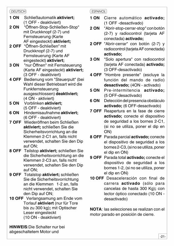
1 ON Schließautomatik aktiviert;(1 OFF - deaktiviert)
2 ON "Öffnen-Stop-Schließen-Stop"mit Druckknopf (2-7) undFernsteuerung (KarteAF eingesteckt) aktiviert;
2 OFF "Öffnen-Schließen" mitDruckknopf (2-7) undFernsteuerung (Karte AFeingesteckt) aktiviert;
3 ON "nur Öffnen" mit Fernsteuerung(Karte AF eingesteckt) aktiviert;(3 OFF - deaktiviert)
4 OFF Bedienung vom "Steuerpult" (beiWahl dieser Betriebsart wird dieFunkfernsteuerungausgeschlossen) deaktiviert;(4 ON - aktiviert)
5 ON Vorblinken aktiviert;(5 OFF - deaktiviert)
6 ON Hindemisaufnahme aktiviert;(6 OFF - deaktiviert)
7 OFF Wiederöffnen beim Schließenaktiviert; schließen Sie dieSicherheitsvorrichtung an dieKlemmen 2-C1 an, falls nichtverwendet, schalten Sie den Dipauf ON;
8 OFF Teilstop aktiviert; schließen Siedie Sicherheitsvorrichtung an dieKlemmen 2-C3 an, falls nichtverwendet, schalten Sie den Dipauf ON;
9 OFF Totalstop aktiviert; schließenSie die Sicherheitsvorrichtungan die Klemmen 1-2 an, fallsnicht verwendet, schalten Sieden Dip auf ON;
10 OFF Verlangsamung am Ende vomTorlauf aktiviert (nur für Torebis zu 300 kg); mit OptischerLeser eingesteckt(10 ON - deaktiviert)
HINWEIS:Die Schalter nur beiabgeschaltetem Motor und
�����
1 ON Cierre automático activado;(1 OFF -desactivado)
2 ON "Abrir-stop-cerrar-stop" con botón(2-7) y radiocontrol (tarjeta AFconectada) activado;
2 OFF "Abrir-cerrar" con botón (2-7) yradiocontrol (tarjeta AF conectada)activado;
3 ON "Solo apertura" con radiocontrol(tarjeta AF conectada) activado;(3 OFF-desactivado)
4 OFF "Hombre presente" (escluye lafunción del mando de radio)desactivado; (4ON - activado)
5 ON Pre-intermitencia activado;(5 OFF-desactivado)
6 ON Detección del presencia obstáculoactivado; (6 OFF-desactivado)
7 OFF Reapertura en la fase de cierreactivado; conecte el dispositivode seguridad a los bornes 2-C1,(si no se utiliza, poner el dip enON)
8 OFF Parada parcial activado; conecteel dispositivo de seguridad a losbornes 2-C3, (si no se utiliza, ponerel dip en ON)
9 OFF Parada total activado; conecte eldispositivo de seguridad a losbornes 1-2, (si no se utiliza, ponerel dip en ON)
10 OFF Desaceleración con final decarrera activado (sólo paracancelas de hasta 300 Kg); conlector óptico conectado (10 ON -desactivado)
NOTA: las selecciones se realizan con elmotor parado en posición de cierre.
������
-22-
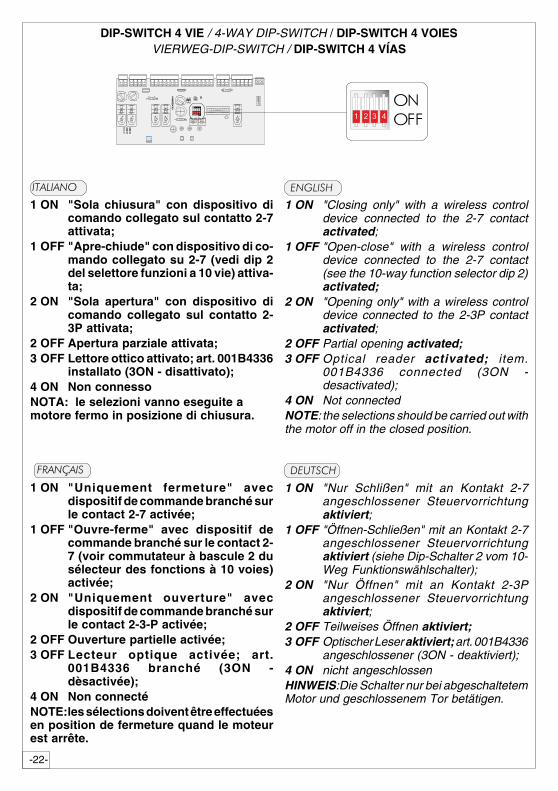
DIP-SWITCH 4 VIE / 4-WAY DIP-SWITCH / DIP-SWITCH 4 VOIESVIERWEG-DIP-SWITCH / DIP-SWITCH 4 VÍAS
���� ��
1 ON "Uniquement fermeture" avecdispositif de commande branché surle contact 2-7 activée;
1 OFF "Ouvre-ferme" avec dispositif decommande branché sur le contact 2-7 (voir commutateur à bascule 2 dusélecteur des fonctions à 10 voies)activée;
2 ON "Uniquement ouverture" avecdispositif de commande branché surle contact 2-3-P activée;
2 OFF Ouverture partielle activée;3 OFF Lecteur optique activée; art.
001B4336 branché (3ON -dèsactivée);
4 ON Non connectéNOTE:les sélections doivent être effectuéesen position de fermeture quand le moteurest arrête.
1 ON "Nur Schlißen" mit an Kontakt 2-7angeschlossener Steuervorrichtungaktiviert;
1 OFF "Öffnen-Schließen" mit an Kontakt 2-7angeschlossener Steuervorrichtungaktiviert (siehe Dip-Schalter 2 vom 10-Weg Funktionswählschalter);
2 ON "Nur Öffnen" mit an Kontakt 2-3Pangeschlossener Steuervorrichtungaktiviert;
2 OFF Teilweises Öffnen aktiviert;3 OFF Optischer Leser aktiviert; art. 001B4336
angeschlossener (3ON - deaktiviert);4 ON nicht angeschlossenHINWEIS:Die Schalter nur bei abgeschaltetemMotor und geschlossenem Tor betätigen.
�����
1 ON "Closing only" with a wireless controldevice connected to the 2-7 contactactivated;
1 OFF "Open-close" with a wireless controldevice connected to the 2-7 contact(see the 10-way function selector dip 2)activated;
2 ON "Opening only" with a wireless controldevice connected to the 2-3P contactactivated;
2 OFF Partial opening activated;3 OFF Optical reader activated; item.
001B4336 connected (3ON -desactivated);
4 ON Not connectedNOTE: the selections should be carried out withthe motor off in the closed position.
�������������
1 ON "Sola chiusura" con dispositivo dicomando collegato sul contatto 2-7attivata;
1 OFF "Apre-chiude" con dispositivo di co-mando collegato su 2-7 (vedi dip 2del selettore funzioni a 10 vie) attiva-ta;
2 ON "Sola apertura" con dispositivo dicomando collegato sul contatto 2-3P attivata;
2 OFF Apertura parziale attivata;3 OFF Lettore ottico attivato; art. 001B4336
installato (3ON - disattivato);4 ON Non connessoNOTA: le selezioni vanno eseguite amotore fermo in posizione di chiusura.
� ����������������
21 43
������� ��
-23-
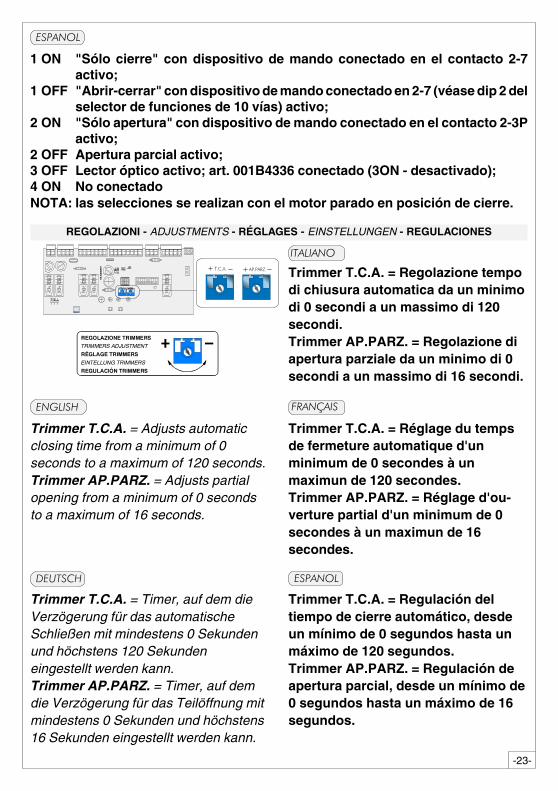
REGOLAZIONI - ADJUSTMENTS - RÉGLAGES - EINSTELLUNGEN - REGULACIONES
1 ON "Sólo cierre" con dispositivo de mando conectado en el contacto 2-7activo;
1 OFF "Abrir-cerrar" con dispositivo de mando conectado en 2-7 (véase dip 2 delselector de funciones de 10 vías) activo;
2 ON "Sólo apertura" con dispositivo de mando conectado en el contacto 2-3Pactivo;
2 OFF Apertura parcial activo;3 OFF Lector óptico activo; art. 001B4336 conectado (3ON - desactivado);4 ON No conectadoNOTA: las selecciones se realizan con el motor parado en posición de cierre.
� ����������������
����������� ���
��������
���� ��
Trimmer T.C.A. = Regolazione tempodi chiusura automatica da un minimodi 0 secondi a un massimo di 120secondi.Trimmer AP.PARZ. = Regolazione diapertura parziale da un minimo di 0secondi a un massimo di 16 secondi.
�����
�����������
� � � � � �� � � �
������������ ���
���������������
����������� ���
������ �������
�������������� ���
Trimmer T.C.A. = Regulación deltiempo de cierre automático, desdeun mínimo de 0 segundos hasta unmáximo de 120 segundos.Trimmer AP.PARZ. = Regulación deapertura parcial, desde un mínimo de0 segundos hasta un máximo de 16segundos.
Trimmer T.C.A. = Réglage du tempsde fermeture automatique d'unminimum de 0 secondes à unmaximun de 120 secondes.Trimmer AP.PARZ. = Réglage d'ou-verture partial d'un minimum de 0secondes à un maximun de 16secondes.
Trimmer T.C.A. = Adjusts automaticclosing time from a minimum of 0seconds to a maximum of 120 seconds.Trimmer AP.PARZ. = Adjusts partialopening from a minimum of 0 secondsto a maximum of 16 seconds.
Trimmer T.C.A. = Timer, auf dem dieVerzögerung für das automatischeSchließen mit mindestens 0 Sekundenund höchstens 120 Sekundeneingestellt werden kann.Trimmer AP.PARZ. = Timer, auf demdie Verzögerung für das Teilöffnung mitmindestens 0 Sekunden und höchstens16 Sekunden eingestellt werden kann.
������
-24-
� ����������������
21 43
��
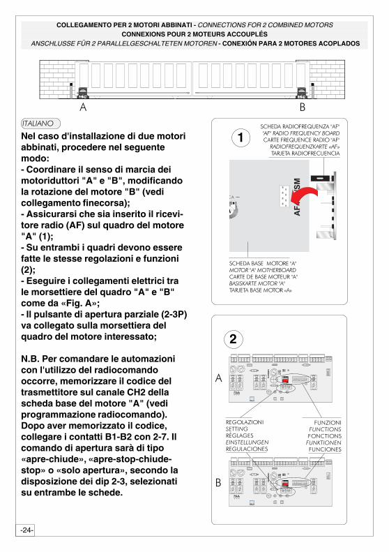
COLLEGAMENTO PER 2 MOTORI ABBINATI - CONNECTIONS FOR 2 COMBINED MOTORSCONNEXIONS POUR 2 MOTEURS ACCOUPLÉS
ANSCHLUSSE FÜR 2 PARALLELGESCHALTETEN MOTOREN - CONEXIÓN PARA 2 MOTORES ACOPLADOS
��������
Nel caso d'installazione di due motoriabbinati, procedere nel seguentemodo:- Coordinare il senso di marcia deimotoriduttori "A" e "B", modificandola rotazione del motore "B" (vedicollegamento finecorsa);- Assicurarsi che sia inserito il ricevi-tore radio (AF) sul quadro del motore"A" (1);- Su entrambi i quadri devono esserefatte le stesse regolazioni e funzioni(2);- Eseguire i collegamenti elettrici trale morsettiere del quadro "A" e "B"come da «Fig. A»;- Il pulsante di apertura parziale (2-3P)va collegato sulla morsettiera delquadro del motore interessato;
N.B. Per comandare le automazionicon l'utilizzo del radiocomandooccorre, memorizzare il codice deltrasmettitore sul canale CH2 dellascheda base del motore "A" (vediprogrammazione radiocomando).Dopo aver memorizzato il codice,collegare i contatti B1-B2 con 2-7. Ilcomando di apertura sarà di tipo«apre-chiude», «apre-stop-chiude-stop» o «solo apertura», secondo ladisposizione dei dip 2-3, selezionatisu entrambe le schede.
������������� ������!�!�������������������
�������������� ��� ��!�!�� ���������������
���"��������� �����#�$
���������������% �����!��!�������� ��������������
���������% �����������!��!��� ����������������
���"������������� �����
1
� �
��������
� ����������� ���
�������������� ���
� �������
��&����������� ��
�'&��&�� ���������
��& ��������
2
� ����������������
21 43
�
�
-25-
���� ��
�����
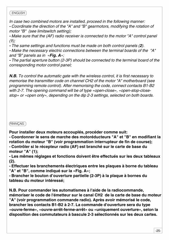
In case two combined motors are installed, proceed in the following manner:- Coordinate the direction of the "A" and "B" gearmotors, modifying the rotation ofmotor "B" (see limitswitch setting);- Make sure that the (AF) radio receiver is connected to the motor "A" control panel(1);- The same settings and functions must be made on both control panels (2).- Make the necessary electric connections between the terminal boards of the "A"and "B" panels as in «Fig. A»;- The partial aperture button (2-3P) should be connected to the terminal board of thecorresponding motor control panel;
N.B. To control the automatic gate with the wireless control, it is first necessary tomemorise the transmitter code on channel CH2 of the motor "A" motherboard (seeprogramming remote control). After memorising the code, connect contacts B1-B2with 2-7. The opening command will be of type «open-close», «open-stop-close-stop» or «open only», depending on the dip 2-3 settings, selected on both boards.
Pour installer deux moteurs accouplés, procéder comme suit:- Coordonner le sens de marche des motoréducteurs "A" et "B" en modifiant larotation du moteur "B" (voir programmation interrupteur de fin de course);- Contrôler si le récepteur radio (AF) est branché sur le carte de base dumoteur "A" (1);- Les mêmes réglages et fonctions doivent être effectués sur les deux tableaux(2).- Effectuer les branchements électriques entre les plaques à borne du tableau"A" et "B", comme indiqué sur la «Fig. A»;- Brancher le bouton d’ouverture partielle (2-3P) à la plaque à bornes dutableau du moteur intéressé;
N.B. Pour commander les automatismes à l'aide de la radiocommande,mémoriser le code de l'émetteur sur le canal CH2 de la carte de base du moteur"A" (voir programmation commande radio). Après avoir mémorisé le code,brancher les contacts B1-B2 à 2-7. La commande d'ouverture sera du type«ouvre-ferme», «ouvre-arrêt-ferme-arrêt» ou «uniquement ouverture», selon ladisposition des commutateurs à bascule 2-3 sélectionnés sur les deux cartes.
-26-
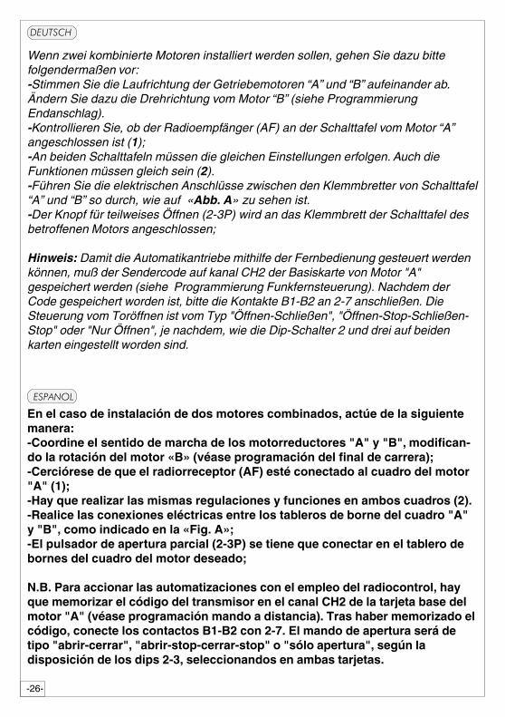
En el caso de instalación de dos motores combinados, actúe de la siguientemanera:-Coordine el sentido de marcha de los motorreductores "A" y "B", modifican-do la rotación del motor «B» (véase programación del final de carrera);-Cerciórese de que el radiorreceptor (AF) esté conectado al cuadro del motor"A" (1);-Hay que realizar las mismas regulaciones y funciones en ambos cuadros (2).-Realice las conexiones eléctricas entre los tableros de borne del cuadro "A"y "B", como indicado en la «Fig. A»;-El pulsador de apertura parcial (2-3P) se tiene que conectar en el tablero debornes del cuadro del motor deseado;
N.B. Para accionar las automatizaciones con el empleo del radiocontrol, hayque memorizar el código del transmisor en el canal CH2 de la tarjeta base delmotor "A" (véase programación mando a distancia). Tras haber memorizado elcódigo, conecte los contactos B1-B2 con 2-7. El mando de apertura será detipo "abrir-cerrar", "abrir-stop-cerrar-stop" o "sólo apertura", según ladisposición de los dips 2-3, seleccionandos en ambas tarjetas.
������
�����
Wenn zwei kombinierte Motoren installiert werden sollen, gehen Sie dazu bittefolgendermaßen vor:-Stimmen Sie die Laufrichtung der Getriebemotoren “A” und “B” aufeinander ab.Ändern Sie dazu die Drehrichtung vom Motor “B” (siehe ProgrammierungEndanschlag).-Kontrollieren Sie, ob der Radioempfänger (AF) an der Schalttafel vom Motor “A”angeschlossen ist (1);-An beiden Schalttafeln müssen die gleichen Einstellungen erfolgen. Auch dieFunktionen müssen gleich sein (2).-Führen Sie die elektrischen Anschlüsse zwischen den Klemmbretter von Schalttafel“A” und “B” so durch, wie auf «Abb. A» zu sehen ist.-Der Knopf für teilweises Öffnen (2-3P) wird an das Klemmbrett der Schalttafel desbetroffenen Motors angeschlossen;
Hinweis: Damit die Automatikantriebe mithilfe der Fernbedienung gesteuert werdenkönnen, muß der Sendercode auf kanal CH2 der Basiskarte von Motor "A"gespeichert werden (siehe Programmierung Funkfernsteuerung). Nachdem derCode gespeichert worden ist, bitte die Kontakte B1-B2 an 2-7 anschließen. DieSteuerung vom Toröffnen ist vom Typ "Öffnen-Schließen", "Öffnen-Stop-Schließen-Stop" oder "Nur Öffnen", je nachdem, wie die Dip-Schalter 2 und drei auf beidenkarten eingestellt worden sind.
-27-
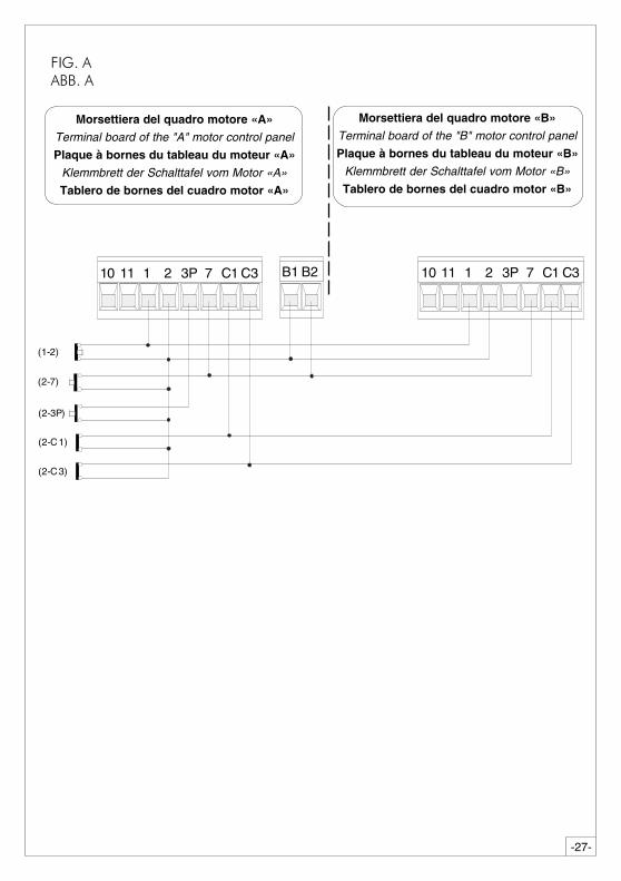
Morsettiera del quadro motore «A»
Terminal board of the "A" motor control panel
Plaque à bornes du tableau du moteur «A»
Klemmbrett der Schalttafel vom Motor «A»
Tablero de bornes del cuadro motor «A»
Morsettiera del quadro motore «B»
Terminal board of the "B" motor control panel
Plaque à bornes du tableau du moteur «B»
Klemmbrett der Schalttafel vom Motor «B»
Tablero de bornes del cuadro motor «B»
��&���������
10 11 1 2 7 C13P C3 B1 10 11 1 2 7 C13P C3B2
(1-2)
(2-7)
(2-3P)
(2-C1)
(2-C3)
-28-
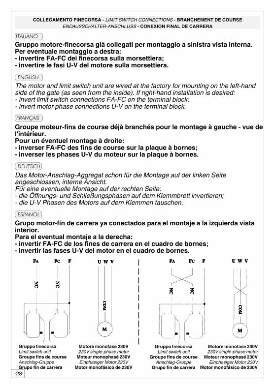
Gruppo motore-finecorsa già collegati per montaggio a sinistra vista interna.Per eventuale montaggio a destra:- invertire FA-FC dei finecorsa sulla morsettiera;- invertire le fasi U-V del motore sulla morsettiera.
The motor and limit switch unit are wired at the factory for mounting on the left-handside of the gate (as seen from the inside). If right-hand installation is desired:- invert limit switch connections FA-FC on the terminal block;- invert motor phase connections U-V on the terminal block.
Groupe moteur-fins de course déjà branchés pour le montage à gauche - vue del'intérieur.Pour un éventuel montage à droite:- inverser FA-FC des fins de course sur la plaque à bornes;- inverser les phases U-V du moteur sur la plaque à bornes.
Das Motor-Anschlag-Aggregat schon für die Montage auf der linken Seiteangeschlossen, interne Ansicht.Für eine eventuelle Montage auf der rechten Seite:- die Öffnungs- und Schließungsphasen auf dem Klemmbrett invertieren;- die U-V Phasen des Motors auf dem Klemmen tauschen.
Grupo motor-fin de carrera ya conectados para el montaje a la izquierda vistainterior.Para el eventual montaje a la derecha:- invertir FA-FC de los fines de carrera en el cuadro de bornes;- invertir las fases U-V del motor en el cuadro de bornes.
COLLEGAMENTO FINECORSA - LIMIT SWITCH CONNECTIONS - BRANCHEMENT DE COURSEENDAUSSCHALTER-ANSCHLUSS - CONEXION FINAL DE CARRERA
��������
�����
���� ��
�����
������
Gruppo finecorsaLimit switch unitGroupe fins de courseAnschlag-GruppeGrupo fin de carrera
Motore monofase 230V230V single-phase motor
Moteur monophasé 230VEinphasiger Motor 230V
Motor monofásico de 230V
Motore monofase 230V230V single-phase motor
Moteur monophasé 230VEinphasiger Motor 230V
Motor monofásico de 230V
Gruppo finecorsaLimit switch unit
Groupe fins de courseAnschlag-Gruppe
Grupo fin de carrera
CO
MC
OM
CO
MC
OM
CO
M
U W VU W VU W VU W VU W V
NC
NC
NC
NC
NC
NC
NC
NC
NC
NC
NC
NC
NC
NC
NC
NC
NC
NC
NC
NC
U W VU W VU W VU W VU W V
CO
MC
OM
CO
MC
OM
CO
M
FFFFFFFFFFCCCCCFFFFFAAAAA FFFFFCCCCCFFFFFAAAAA FFFFF
MMMMMMMMMM
-29-
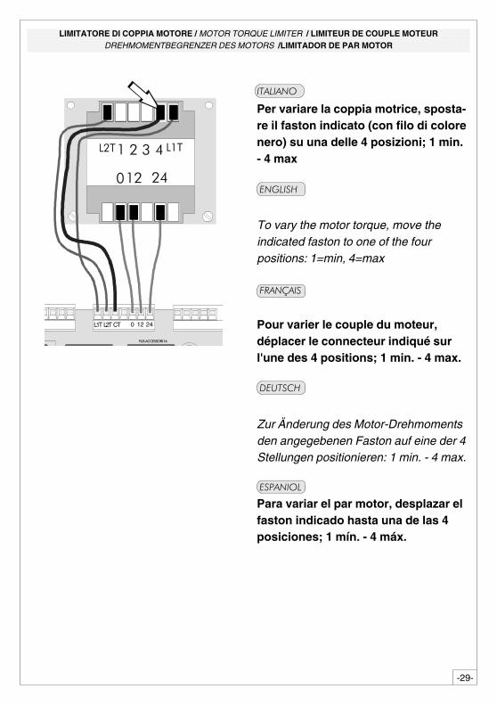
LIMITATORE DI COPPIA MOTORE / MOTOR TORQUE LIMITER / LIMITEUR DE COUPLE MOTEURDREHMOMENTBEGRENZER DES MOTORS /LIMITADOR DE PAR MOTOR
Per variare la coppia motrice, sposta-re il faston indicato (con filo di colorenero) su una delle 4 posizioni; 1 min.- 4 max
To vary the motor torque, move theindicated faston to one of the fourpositions: 1=min, 4=max
Pour varier le couple du moteur,déplacer le connecteur indiqué surl'une des 4 positions; 1 min. - 4 max.
Zur Änderung des Motor-Drehmomentsden angegebenen Faston auf eine der 4Stellungen positionieren: 1 min. - 4 max.
��������
�����
���� ��
�������
�����
Para variar el par motor, desplazar elfaston indicado hasta una de las 4posiciones; 1 mín. - 4 máx.
� � ���� ���
� ����
� ����������������
L1T 0 12 24L2T CT
-30-
ENGLISH
PROCEDURE
A. insert an
AF card **.
B. encodetransmitter/s.
C. store code inthemotherboard.
FRANÇAIS
PROCEDURE
A. placer unecarte AF **.
B. codifier le/sémetteur/s.
C. mémoriser lacodificationsur la cartebase.
DEUTSCH
PROZEDUR
A. Stecken Sieeine Karte
AF **.
B. Codieren Sieden/dieSender.
C. Speichern Siedie Codierungauf derGrundplatine.
ITALIANO
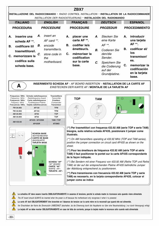
PROCEDURA
A. inserire una
scheda AF **.
B. codificare il/i
trasmettitore/i.
C. memorizzare la
codifica sulla
scheda base.
zHM/azneuqerFzHM/ycneuqerFzHM/ecneuqerF
zHM/zneuqerFzHM/aicneucerF
azneuqerfoidaradehcSdraobycneuqerfoidaRecneuqérfoidaretraC
enitalP-zneuqerfknuFaicneucerfoidaratejraT
erotittemsarTrettimsnarT
ruettemErednesknuFrosimsnarT
599.62MF 031FA MFT
009.03MF 051FA MFT
599.62MA 62FA POT
009.03MA 03FA POT
29.334MAMS34FA/S34FA POT/MAT
RS34FA OMOTA
ZBX7INSTALLAZIONE DEL RADIOCOMANDO - RADIO CONTROL INSTALLATION - INSTALLATION DE LA RADIOCOMMANDE
INSTALLATION DER RADIOSTEUERUNG - INSTALACIÓN DEL RADIOMANDO
ESPANOL
PROCEDIMIENTO
A. introduciruna tarjetaAF **.
B. codificar el/lostransmisor/es.
C. memorizar lacodificaciónen la tarjetabase.
(**) Per trasmettitori con frequenza 433.92 AM (serie TOP e serie TAM)bisogna, sulla relativa scheda AF43S, posizionare il jumper comeillustrato.
(**) On AM transmitters operating at 433.92 MHz (TOP and TAM series),position the jumper connection on circuit card AF43S as shown on thesheet.
(**) Pour les émetteurs de fréquence 433.92 AM (série TOP et sérieTAM) il faut positionner le pontet sur la carte AF43S correspondantede la façon indiquée.
(**) Bei Sendern mit einer Frequenz von 433.92 AM (Reihe TOP und ReiheTAM) ist der auf der entsprechenden Platine AF43S befindliche Jumperder Abbildung entsprechend zu positionieren.
(**) Para transmisores con frecuencia 433.92 AM (serie TOP y serieTAM) es necesario, en la tarjeta corespondiente AF43S, colocar eljumper como se indica
TOP TAM
SCHEDA BASEMOTHERBOARDCARTE DE BASEBASISKARTETARJETA BASE
SCHEDA "AF""AF" BOARDCARTE "AF"KARTE «AF»TARJETA «AF»
La schedina AF deve essere inserita OBBLIGATORIAMENTE in assenza di tensione, perché la scheda madre la riconosce solo quando viene alimentata
The AF board should ALWAYS be inserted when the power is off because the motherboard only recognises it when it is powered.
La carte AF doit OBLIGATOIREMENT être branchée en l’absence de tension car la carte mère ne la reconnaît que quand elle est alimentée.
Vor Einschieben der Karte die Stromzufuhr UNBEDINGT abschalten, da die Erkennung durch die Hauptkarte nur über eine Neueinschaltung ( nur durch Versorgung) erfolgt.
La tarjeta AF se debe montar OBLIGATORIAMENTE en caso de falta de corriente, porque la tarjeta madre la reconoce sólo cuando está alimentada
INSERIMENTO SCHEDA AF - AF BOARD INSERTION - NSTALLATION DE LA CARTE AFEINSTECKEN DER KARTE AF / MONTAJE DE LA TARJETA AFA
��
-31-
AT01 - AT02
vedi foglio istruzioni inserito nella confezionedella scheda AF43SR
see instruction sheet inside the pack of AF43SR circuit cardvoir les instructions qui se trouve dans l'emballage
de la carte AF43SRSiehe Anleitungen, die der Packung beiliegen der Platine AF43SR
ver hoja de instrucciones adjunta en el embalajede la tarjeta AF43SR
ATOMO
CODIFICA TRASMETTITORI - TRANSMITTER ENCODING - CODIFICATION DES EMETTEURS
CODIERUNG DER SENDER - CODIFICACIÓN TRANSMISORESB
vedi istruzioni su confezionesee instructions on pack
voir instructions sur l'emballageSiehe Anleitungen auf der Packung.ver instrucciones en el embalaje
T432S / T432SA
TOP
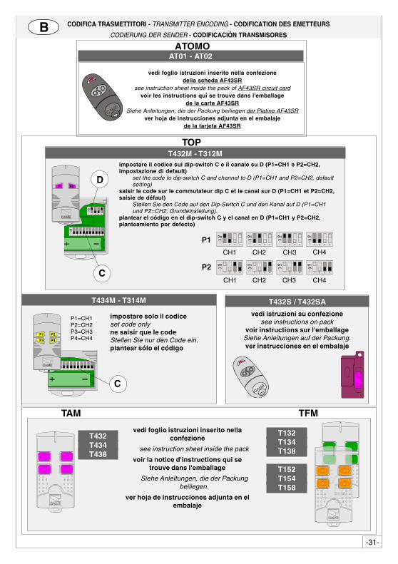
impostare il codice sul dip-switch C e il canale su D (P1=CH1 e P2=CH2,impostazione di default)
set the code to dip-switch C and channel to D (P1=CH1 and P2=CH2, defaultsetting)
saisir le code sur le commutateur dip C et le canal sur D (P1=CH1 et P2=CH2,saisie de défaut)
Stellen Sie den Code auf den Dip-Switch C und den Kanal auf D (P1=CH1und P2=CH2; Grundeinstellung).
plantear el código en el dip-switch C y el canal en D (P1=CH1 y P2=CH2,planteamiento por defecto)
T432M - T312M
1 2 3 4 5 6 7 8 9 10
1 2 3 4
C
DP1 P2
P2
CH1 CH2 CH3 CH4
P1
CH1 CH2 CH3 CH41 2 3 4 1 2 3 4 1 2 3 41 2 3 4
1 2 3 4 1 2 3 4 1 2 3 4 1 2 3 4
vedi foglio istruzioni inserito nellaconfezione
see instruction sheet inside the pack
voir la notice d'instructions qui setrouve dans l'emballage
Siehe Anleitungen, die der Packungbeiliegen.
ver hoja de instrucciones adjunta en elembalaje
TAM
T132T134T138
T152T154T158
T432T434T438
TFM
T434M - T314M
impostare solo il codiceset code onlyne saisir que le codeStellen Sie nur den Code ein.plantear sólo el código
P1=CH1P2=CH2P3=CH3P4=CH4
1 2 3 4 5 6 7 8 9 10
C
P1 P2
P3 P4
-32-
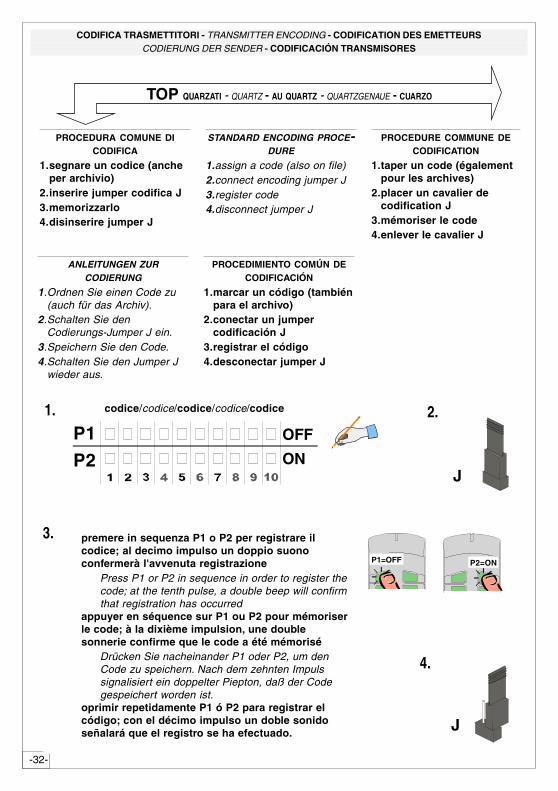
PROCEDURA COMUNE DICODIFICA
1.segnare un codice (ancheper archivio)
2.inserire jumper codifica J3.memorizzarlo4.disinserire jumper J
STANDARD ENCODING PROCE-DURE
1.assign a code (also on file)2.connect encoding jumper J3.register code4.disconnect jumper J
PROCEDURE COMMUNE DECODIFICATION
1.taper un code (égalementpour les archives)
2.placer un cavalier decodification J
3.mémoriser le code4.enlever le cavalier J
ANLEITUNGEN ZURCODIERUNG
1.Ordnen Sie einen Code zu(auch für das Archiv).
2.Schalten Sie denCodierungs-Jumper J ein.
3.Speichern Sie den Code.4.Schalten Sie den Jumper J
wieder aus.
PROCEDIMIENTO COMÚN DECODIFICACIÓN
1.marcar un código (tambiénpara el archivo)
2.conectar un jumpercodificación J
3.registrar el código4.desconectar jumper J
premere in sequenza P1 o P2 per registrare ilcodice; al decimo impulso un doppio suonoconfermerà l'avvenuta registrazione
Press P1 or P2 in sequence in order to register thecode; at the tenth pulse, a double beep will confirmthat registration has occurred
appuyer en séquence sur P1 ou P2 pour mémoriserle code; à la dixième impulsion, une doublesonnerie confirme que le code a été mémorisé
Drücken Sie nacheinander P1 oder P2, um denCode zu speichern. Nach dem zehnten Impulssignalisiert ein doppelter Piepton, daß der Codegespeichert worden ist.
oprimir repetidamente P1 ó P2 para registrar elcódigo; con el décimo impulso un doble sonidoseñalará que el registro se ha efectuado.
2.
J
3.
ON
OFFP1
P2
codice/codice/codice/codice/codice1.
4.
J
P1=OFF P2=ON
TOP QUARZATI - QUARTZ - AU QUARTZ - QUARTZGENAUE - CUARZO
CODIFICA TRASMETTITORI - TRANSMITTER ENCODING - CODIFICATION DES EMETTEURSCODIERUNG DER SENDER - CODIFICACIÓN TRANSMISORES
-33-
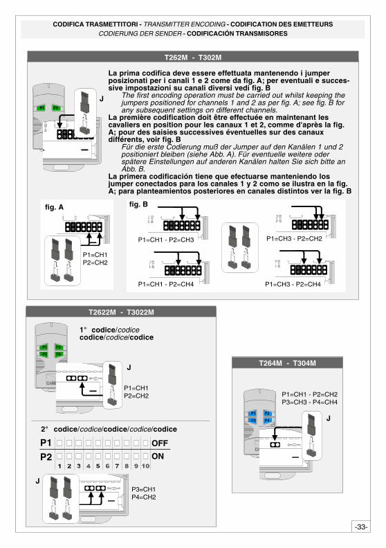
La prima codifica deve essere effettuata mantenendo i jumperposizionati per i canali 1 e 2 come da fig. A; per eventuali e succes-sive impostazioni su canali diversi vedi fig. B
The first encoding operation must be carried out whilst keeping thejumpers positioned for channels 1 and 2 as per fig. A; see fig. B forany subsequent settings on different channels.
La première codification doit être effectuée en maintenant lescavaliers en position pour les canaux 1 et 2, comme d'après la fig.A; pour des saisies successives éventuelles sur des canauxdifférents, voir fig. B
Für die erste Codierung muß der Jumper auf den Kanälen 1 und 2positioniert bleiben (siehe Abb. A). Für eventuelle weitere oderspätere Einstellungen auf anderen Kanälen halten Sie sich bitte anAbb. B.
La primera codificación tiene que efectuarse manteniendo losjumper conectados para los canales 1 y 2 como se ilustra en la fig.A; para planteamientos posteriores en canales distintos ver la fig. B
T262M - T302M
P1 P2
J
T2622M - T3022M
P1 P2
P3 P4
P1=CH1 - P2=CH2P3=CH3 - P4=CH4
J
T264M - T304M
P1=CH1P2=CH2
fig. A
2° codice/codice/codice/codice/codice
ON
OFFP1P2
P3=CH1P4=CH2
J
1° codice/codicecodice/codice/codice
P1 P2
P3 P4
P1=CH1P2=CH2
J
fig. B
P1=CH1 - P2=CH4
P1=CH1 - P2=CH3 P1=CH3 - P2=CH2
P1=CH3 - P2=CH4
CODIFICA TRASMETTITORI - TRANSMITTER ENCODING - CODIFICATION DES EMETTEURSCODIERUNG DER SENDER - CODIFICACIÓN TRANSMISORES
-34-
MEMORIZZAZIONE CODICE - CODE STORAGE - MEMORISATION DU CODESPEICHERN VOM CODE - MEMORIZACIÓN CÓDIGOC
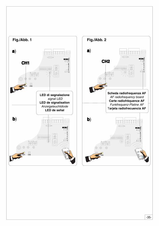
a) Drücken Sie dieTaste "CH1" auf derBasiskarte und haltenSie die gedrückt(LED blinkt);b) Mit einer Tastevom Sender wird derCode abgeschickt.Das LED hört auf zublinken und bleibt an,sobald das Speichernerfolgt ist (Abb.1)Gehen Sie ebensomit Taste "CH2" vorund ordnen sie ihreine andere Tastedes Senders zu(Abb.2).CH1 = Kanal für dieDirektsteuerung einerFunktion desGetriebemotor-Schaltkastens(Steuerung "nurÖffnen" / "Öffnen-Schließen-Sicherheitsrücklauf"bzw. "Öffnen-Stp-Schließen-Stop", jenach über Dip-Switch2 und 3 ausgeführterWahl).CH2 = Kanal fürDirektsteuerung einesüber B1-B2angeschlossenenZubehörs.
Hinweis: beieventuell erwünschterSendercodeänderung ist derbeschriebeneVorgang zuwiederholen.
DEUTSCH
a) appuyer pendantquelques secondessur la touche "CH1"située sur la carte debase (le voyant designalisationclignote);b) saisir le code àl'aide d'une touchede l'émetteur, levoyant reste allumépour signaler que lamémorisation a étéeffectuée (fig.1).Suivre la mêmeprocédure avec latouche "CH2" enl'associant avec uneautre touche duemetteur (fig.2).CH1 = Canal pourobtenir la commandedirecte d'unefonction du boîtierdu motoréducteur (commande"uniquementouverture" /"ouverture-fermeture-inversion"ou "ouverte-stop-ferme-stop" enfonction de lasélection effectuéesur les dip-switchs 2et 3).CH2 = Canal pourobtenir la commandedirecte d'undispositif accessoirebranché sur B1-B2.
Remarque: si,successivement, onveut changer le codedes émetteur, il suffitde répéter laséquence décrite ci-dessus.
FRANÇAIS
a) press down andhold the "CH1" key onthe base board (thesignal LED will flash);b) send the code witha button on thetransmitter, the LEDwill remain lit toindicate that the datahas been saved place(fig.1).Perform the sameprocedure with the"CH2" key,associating it withanother transmitterkey (fig.2).CH1 = Channel fordirect control of onefunction performed bythe control unit on thegear motor ("openonly" / "open-close-reverse" or "open-stop-close-stop",depending on theposition of dipswitches 2 and 3).CH2 = Channel fordirect control of anaccessory connectedacross B1-B2.
N.B. If you wish tochange the code onyour transmitters inthe future, simplyrepeat the proceduredescribed above.
ENGLISH
a) mantengaapretada la tecla"CH1" en la tarjetabase (el indicadorluminoso de señalparpadea);b) con la tecla deltransmisor se envíael código, elindicador luminosopermaneceencendido paraindicar que lamemorización se hallevado a cabo (fig.1).Efectuar el mismoprocedimiento con latecla "CH2"asociándola a otratecla del transmisor(fig.2).CH1 = Canal paramando directo a unafunción de la centraldel motorreductor(mando "solo abre" /"abre-cierra-inversión" o "abre-stop-cierra-stop",según la selecciónefectuada en los dip-switch 2 y 3).CH2 = Canal para unmando directo a undispositivoaccesorio conectadoen B1-B2.Nota: si posterior-mente se quisieracambiar el código delos propiostransmisores, sólohay que repetir lasecuencia descrita.
ESPANOL
a) tenere premuto iltasto "CH1" sullascheda base, il led disegnalazionelampeggia;b) con un tasto deltrasmettitore s'inviail codice, il ledrimarrà acceso asegnalare l'avvenutamemorizzazione(fig.1).Eseguire la stessaprocedura con iltasto "CH2"associandolo con unaltro tasto deltrasmettitore (fig.2).CH1 = Canale percomandi diretti aduna funzione dellacentralina delmotoriduttore(comando "soloapre" / "apre-chiude-inversione" oppure"apre-stop-chiude-stop", a secondadella selezioneeffetuata sui dip-switch 2 e 3).CH2 = Canale percomandi diretti ad undispositivoaccessorio, collegatosu B1-B2.
N.B.: se in seguito sivuol cambiarecodice, ripetere lasequenza descritta.
ITALIANO
-35-
CH1 CH2
CH1 CH2CH1 CH2
CH1 CH2
LED di segnalazione signal LED
LED de signalisationAnzeigeleuchtdiode
LED de señal
aaaaa)
bbbbb)
CH1CH1CH1CH1CH1
Scheda radiofrequenza AFAF radiofrequency board
Carte radiofrèquence AFFunkfrequenz-Platine AF
Tarjeta radiofrecuencia AF
aaaaa)
CH2CH2CH2CH2CH2
bbbbb)
Fig./Abb. 2Fig./Abb. 1
-36-
CAME LOMBARDIA S.R.L.___COLOGNO M. (MI)(+39) 02 26708293 (+39) 02 25490288
CAME SUD S.R.L. _________________NAPOLI(+39) 081 752445 (+39) 081 7529109
CAME (AMERICA) L.L.C._________MIAMI (FL)(+1) 305 5930227 (+1) 305 5939823
CAME AUTOMATISMOS S.A_________MADRID(+34) 091 5285009 (+34) 091 4685442
CAME BELGIUM____________LESSINES(+32) 068 333014 (+32) 068 338019
CAME CANCELLI AUTOMATICI S.P.A.DOSSON DI CASIER (TREVISO)
(+39) 0422 (+39) 0422 490944
CANCELLI AUTOMATICI
CAME FRANCE S.A.___NANTERRE CEDEX (PARIS)(+33) 01 46130505 (+33) 01 46130500
CAME GMBH____KORNTAL BEI (STUTTGART)(+49) 07 11839590 (+49) 07 118395925
CAME GMBH________SEEFELD BEI (BERLIN)(+49) 03 33988390 (+49) 03 339885508
CAME PL SP.ZO.O_________WARSZAWA(+48) 022 8699933 (+48) 022 6399933
CAME UNITED KINGDOM LTD___NOTTINGHAM(+44) 01159 387200 (+44) 01159 382694
ASSISTENZA TECNICA
NUMERO VERDE
800 295830
WEBwww.came.it
SISTEMA QUALITÀCERTIFICATO
NOTE - NOTE - NOTE - HINWEIS - NOTA