Embed Size (px)
Citation preview

915S E R I E S
MANUAL
Specifications are subject to modification without prior notice.
ALCAD S.L. designs and manufactures its products to the highest possible standards. However, the specifications of products currently being manufactured may be modified to take advantage of newly available components or to improve performance. In such cases it is possible that the latest specifications may not appear in this manual. Future editions of the manual will be updated, however, to take account of any changes.
In the meantime, our web site (www.alcad.net) provides all the latest information concerning our products, including up-to-date specifications..
ENGLISH
3
PAGE
www.alcad.net

3 CONTENTS4 915-SV SERIES 4 SAFETY INSTRUCTIONS 6 DESCRIPTION 6 Description of the power supply unit7 Description of the SV-200 module 7 INSTALLATION7 Power supply of the equipment 8 PROGRAMMING OF THE SV MODULE 11 INTRODUCTION TO THE ALCAD IPTV WEB CONFIGURATOR 12 DESCRIPTION OF THE ALCAD IPTV WEB CONFIGURATOR 13 MENUS OF THE ALCAD IPTV WEB CONFIGURATOR 13 Status17 Network 24 Maintenance 29 EXAMPLE OF CONFIGURATION AND OPERATION 39 TROUBLE SHOOTING
PÁG.
ENG ALCAD IPTV web configurator manual - 3
915-SV SERIES
The A/V to IP streaming equipment (915-SV) broadcasts both multicast streams and programmes, from a maximum of 2 audio-video devices connected to the equipment, over a TCP-IP network.
TV services broadcast as IPTV streams can be viewed on an individual IPTV receiver or by using video playback software
The SV modules are mounted in an SP-725 19” rack (code 9120136). It is possible to connect up to eight SV-200 modules per power supply unit. Each SV module can handle a maximum of two MPEG streams; the IP broadcast, therefore, consists of two A/V services per module.
The SV modules are configured via TCP/IP, using either the HTTP protocol (web browser) or TELNET (virtual terminal).
SAFETY INSTRUCTIONS
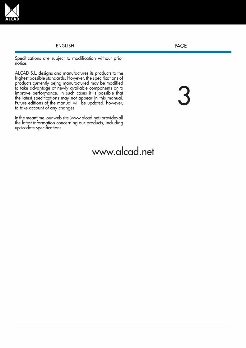
Make all the A/V and power connections before connecting the equipment to the mains supply. To comply with safety regulations, the electrical installation must be protected using a differential circuit-breaker
Fig.1 - Earthing the equipment
Do not remove the covers of the equipment while it is connected to the mains. All repairs must be carried out by authorised technical personnel. Any internal manipulation of the equipment will annul all warranties.
Make sure that the equipment is properly ventilated.
ENG4 - ALCAD IPTV web configurator manual
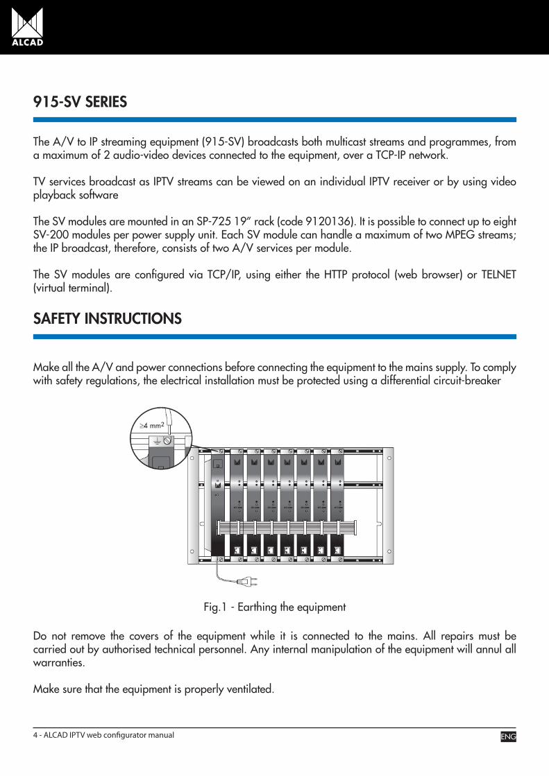
Equipment operating outside its temperature range (-10°C to +65°C) may be damaged beyond repair. Do not block or cover the ventilation slots of the power supply unit.
Fig.2 - Do not handle while the equipment is connected
If you have any doubts regarding the installation, operation or safety requirements of the equipment, consult your supplier.
ENG ALCAD IPTV web configurator manual - 5
DESCRIPTION
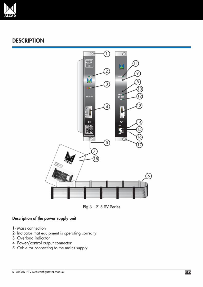
Fig.3 - 915-SV Series
Description of the power supply unit
1- Mass connection 2- Indicator that equipment is operating correctly 3- Overload indicator4- Power/control output connector 5- Cable for connecting to the mains supply
ENG6 - ALCAD IPTV web configurator manual
6- Power/control cable7- Technical datasheet
Description of the SV-200 module
8- JACK connector for audio/video signal input from the originating device to ENCODER 1 9- JACK connector for audio/video signal input from the originating device to ENCODER 210- Indicator that the input connector of ENCODER 1 is available. 11- Indicator that the input connector of ENCODER 2 is available.12- Indicator that transport stream processor is correct13- Power/control connector 14- Indicator that Ethernet link is correct15- RJ-45 output port 16- Indicator of Ethernet activity 17- Mass connection 18- Technical datasheet
INSTALATION
Supplying power to the equipment
When all the A/V signal connections and power connections of the modules have been made, connect the equipment to the electrical mains.
To power the equipment, it is necessary to connect all the modules to the SP-725 19” rack (code 9120136), which earths the equipment.
ENG ALCAD IPTV web configurator manual - 7

PROGRAMMING THE SV MODULE
When the A/V to IP streaming equipment (915-SV) has been assembled, each SV module can then be configured.
All SV modules leave the factory with the following IP address: 192.168.10.100. To avoid conflicts with other IP addresses, it is necessary to perform an initial configuration in local mode. Subsequently, it will be possible to access the A/V to IP streaming equipment (915-SV) via the local area network (LAN), either to reprogram it or to check is operating status.
Fig.4 - Configuration in local mode
ENG8 - ALCAD IPTV web configurator manual
CO
NEX
IÓN
A L
A R
ED D
E Á
REA
LO
CA
L (L
AN
)C
ON
NEC
TIO
N T
O T
HE
LAN
CO
NN
EXIO
N A
U R
ESEA
U L
OC
AL
(LA
N)
1 G
b (m
ax 1
00 m
)C
AT-5
e /
CAT
-6
SS-1
00
Build
ing
distr
ibut
or
19"
Rack IG
MP
1 G
b (m
ax 1
00 m
)C
AT-5
e /
CAT
-6
F.O
. 1G
B (S
X/LX
mul
timod
e m
ax 5
50 m
)
(LX
m
onom
ode
max
500
0 m
)
Cam
pus
distr
ibut
or
19"
Rack IG
MP
SS-1
10ST
-100
ST-1
10SV
-200
DVB
-T
DVB
-S2
DVB
-S
TV
19"
Rack
IGM
P
100
Mb
(max
100
m)
CAT
-5e
/ C
AT-6
TV
STB-
020
STB-
020
TV
STB-
020
TV
STB-
020
Floo
r dist
ribut
or
Floo
r dist
ribut
or
19"
Rack
IGM
P
100
Mb
(max
100
m)
CAT
-5e
/ C
AT-6
Ethe
rnet
cab
leC
AT-5
e /
CAT
6
Ethe
rnet
cab
leC
AT-5
e /
CAT
6
ENG ALCAD IPTV web configurator manual - 9

As mentioned above, the SV modules leave the factory with the following TCP/IP configuration:
IP address of the module: 192.168.10.100 Subnet mask: 255.255.255.0
Default Gateway: 192.168.10.1
To access each SV module, use a PC or MAC personal computer equipped with an Ethernet card and an RJ-45 cable (CAT-5E or CAT-6).
The IP address of the PC/MAC must be configured within the following range: 192.168.10.2 – 192.168.10.254
(do not use 192.168.10.100, since this is the IP address of the module to be configured).
To start the configuration of the SV module, open your web browser and type in the following address: http://192.168.10.100.
The first page of the ALCAD IPTV configuration program will appear on the screen. Access to the site is protected by username and password, so that once the default key has been changed, the only people who can enter the site will be those who have been provided with a permanent key by the installation company. By default, the first time the module is accessed, the key is:
User: alcad Password: alcad
Fig.5 - Initial screen
ENG10 - ALCAD IPTV web configurator manual
INTRODUCTION TO THE ALCAD IPTV WEB CONFIGURATOR
As explained above, the SV modules are configured using a graphical menu displayed on a web page. Using this menu, it is possible to move through the different configuration screens so as to set all the parameters of the module.
Navigation between the different configuration screens is intuitive and very simple. On the following pages we explain how to access each screen.
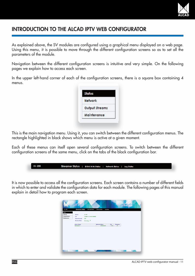
In the upper left-hand corner of each of the configuration screens, there is a square box containing 4 menus.
This is the main navigation menu. Using it, you can switch between the different configuration menus. The rectangle highlighted in black shows which menu is active at a given moment.
Each of these menus can itself open several configuration screens. To switch between the different configuration screens of the same menu, click on the tabs of the black configuration bar.
It is now possible to access all the configuration screens. Each screen contains a number of different fields in which to enter and validate the configuration data for each module. The following pages of this manual explain in detail how to program each screen.
ENG ALCAD IPTV web configurator manual - 11
DESCRIPTION OF THE ALCAD IPTV WEB CONFIGURATOR
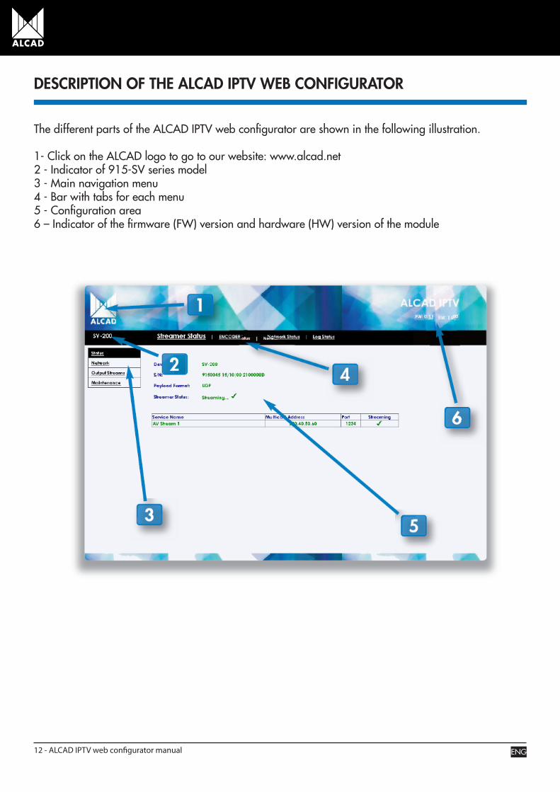
The different parts of the ALCAD IPTV web configurator are shown in the following illustration.
1- Click on the ALCAD logo to go to our website: www.alcad.net 2 - Indicator of 915-SV series model3 - Main navigation menu4 - Bar with tabs for each menu 5 - Configuration area6 – Indicator of the firmware (FW) version and hardware (HW) version of the module
ENG12 - ALCAD IPTV web configurator manual
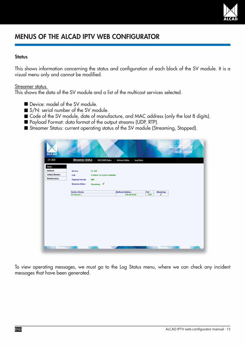
Status
This shows information concerning the status and configuration of each block of the SV module. It is a visual menu only and cannot be modified.
Streamer status This shows the data of the SV module and a list of the multicast services selected.
Device: model of the SV module. S/N: serial number of the SV module. Code of the SV module, date of manufacture, and MAC address (only the last 8 digits). Payload Format: data format of the output streams (UDP, RTP). Streamer Status: current operating status of the SV module (Streaming, Stopped).
MENUS OF THE ALCAD IPTV WEB CONFIGURATOR
To view operating messages, we must go to the Log Status menu, where we can check any incident messages that have been generated.
ENG ALCAD IPTV web configurator manual - 13

ENCODER statusThis shows the status of the encoders associated to the composite video signal inputs.
ENG14 - ALCAD IPTV web configurator manual
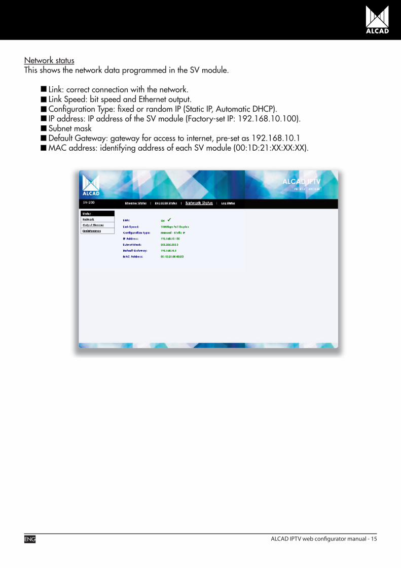
Network statusThis shows the network data programmed in the SV module.
Link: correct connection with the network. Link Speed: bit speed and Ethernet output. Configuration Type: fixed or random IP (Static IP, Automatic DHCP). IP address: IP address of the SV module (Factory-set IP: 192.168.10.100). Subnet mask Default Gateway: gateway for access to internet, pre-set as 192.168.10.1 MAC address: identifying address of each SV module (00:1D:21:XX:XX:XX).
ENG ALCAD IPTV web configurator manual - 15
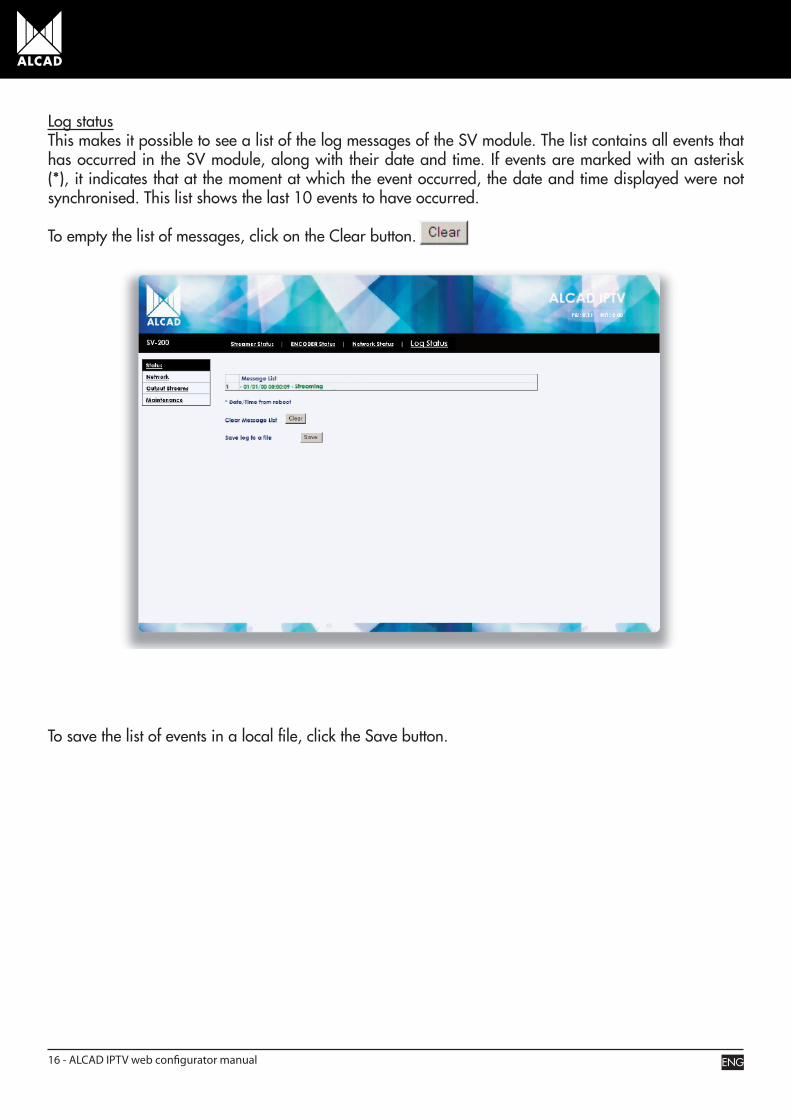
Log statusThis makes it possible to see a list of the log messages of the SV module. The list contains all events that has occurred in the SV module, along with their date and time. If events are marked with an asterisk (*), it indicates that at the moment at which the event occurred, the date and time displayed were not synchronised. This list shows the last 10 events to have occurred.
To empty the list of messages, click on the Clear button.
To save the list of events in a local file, click the Save button.
ENG16 - ALCAD IPTV web configurator manual
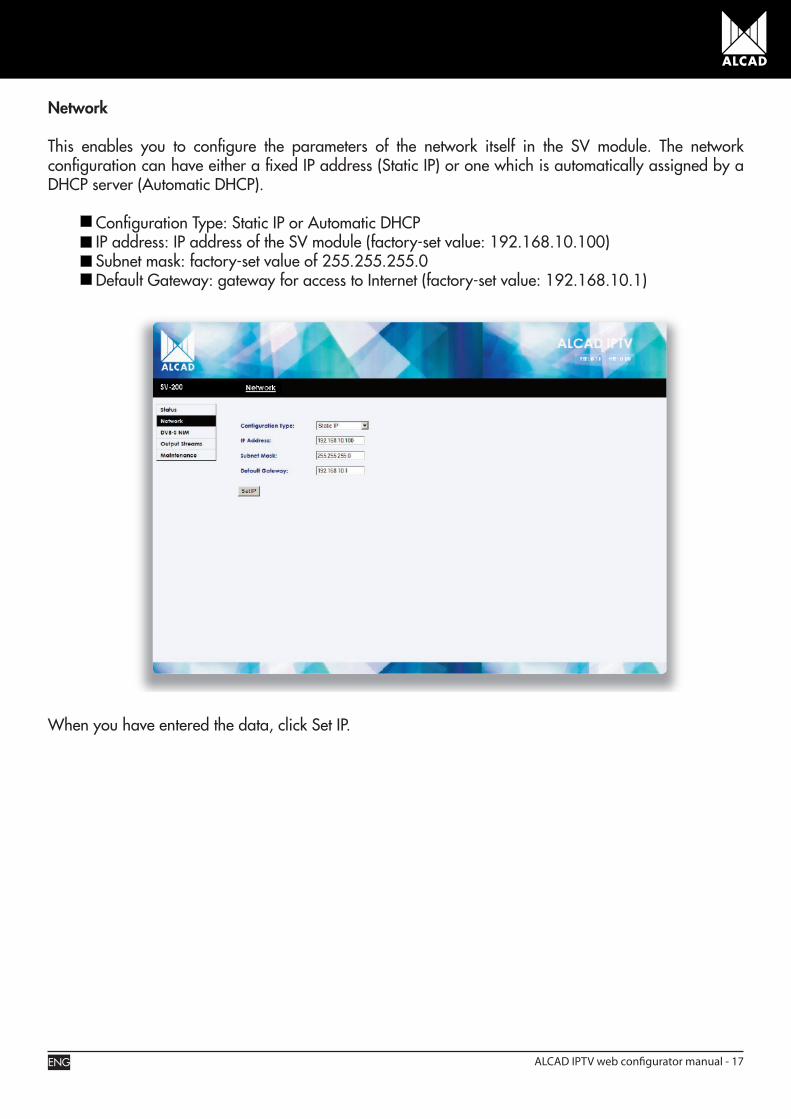
Network
This enables you to configure the parameters of the network itself in the SV module. The network configuration can have either a fixed IP address (Static IP) or one which is automatically assigned by a DHCP server (Automatic DHCP).
Configuration Type: Static IP or Automatic DHCP IP address: IP address of the SV module (factory-set value: 192.168.10.100) Subnet mask: factory-set value of 255.255.255.0 Default Gateway: gateway for access to Internet (factory-set value: 192.168.10.1)
When you have entered the data, click Set IP.
ENG ALCAD IPTV web configurator manual - 17
Output Stream
This lets you activate/deactivate the encoders of the audio/video to be broadcast over the TCP/IP network.
Encoder Configuration
This makes it possible to activate/deactivate any of the A/V inputs and to configure the way in which they are encoded (service quality and aspect ratio), thereby creating the services which will be broadcast over the TCP/IP network
Service Name: the name that will be assigned to the service and be shown on the Multicast Assignment screen. Service Quality: the quality level at which the service will be encoded for broadcasting (factory- set value: Very High Quality VBR). Very High Quality CBR High Quality CBR Medium Quality CBR Low Quality CBR Very High Quality VBR High Quality VBR Medium Quality VBR Low Quality VBR Aspect Ratio: the aspect ratio at which the image will be broadcast (factory-set value: 4:3). 4:3 16:9. Open Matte Format: this activates the “open matte” or “borderless” format. The borders of the 16:9 format are removed, with the result that the service is played back in “fullscreen” mode (available only for Service Quality: High Quality CBR/VBR and Very High Quality CBR/VBR with Aspect Ratio 16:9). Selected: this shows if the service is or is not selected to be broadcast.
ENG18 - ALCAD IPTV web configurator manual

To confirm the selection, click on the Apply button.
Advanced users have the possibility of opening a menu with further configuration options for the services to be broadcast. To open this menu, press the Select Params button.
ENG ALCAD IPTV web configurator manual - 19
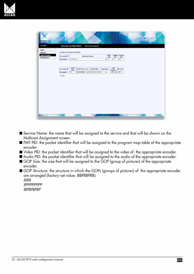
Service Name: the name that will be assigned to the service and that will be shown on the Multicast Assignment screen. PMT PID: the packet identifier that will be assigned to the program map table of the appropriate encoder. Video PID: the packet identifier that will be assigned to the video of the appropriate encoder. Audio PID: the packet identifier that will be assigned to the audio of the appropriate encoder. GOP Size: the size that will be assigned to the GOP (group of pictures) of the appropriate encoder. GOP Structure: the structure in which the GOPs (groups of pictures) of the appropriate encoder are arranged (factory-set value: IBBPBBPBB). IIIIIIII IPPPPPPPPP IBPBPBPBP
ENG20 - ALCAD IPTV web configurator manual
Video Filter: the video filtering mode that will be applied to the appropriate encoder (factory-set value: STANDARD). SOFT STANDARD SHARP. Resolution: the resolution that will be applied to the image of the appropriate encoder (factory-set value: D1). D1. HD1 SIF QSIF 2/3 D1 3/4 D1 BR Mode: the application mode of the bit rate of the appropriate encoder (factory-set value: VBR). CBR VBR Bit Rate: the bit rate value that will be assigned to the appropriate encoder (factory-set value: 12288).
To confirm the selection, click on the Apply button.
ENG ALCAD IPTV web configurator manual - 21
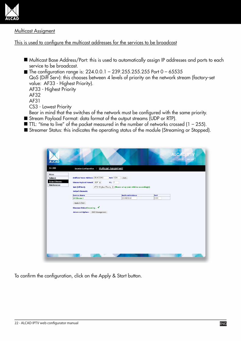
Multicast Assigment
This is used to configure the multicast addresses for the services to be broadcast
Multicast Base Address/Port: this is used to automatically assign IP addresses and ports to each service to be broadcast. The configuration range is: 224.0.0.1 – 239.255.255.255 Port 0 – 65535 QoS (Diff Serv): this chooses between 4 levels of priority on the network stream (factory-set value: AF33 - Highest Priority). AF33 - Highest Priority AF32 AF31 CS3 - Lowest Priority Bear in mind that the switches of the network must be configured with the same priority. Stream Payload Format: data format of the output streams (UDP or RTP). TTL: “time to live” of the packet measured in the number of networks crossed (1 – 255). Streamer Status: this indicates the operating status of the module (Streaming or Stopped).
To confirm the configuration, click on the Apply & Start button.
ENG22 - ALCAD IPTV web configurator manual
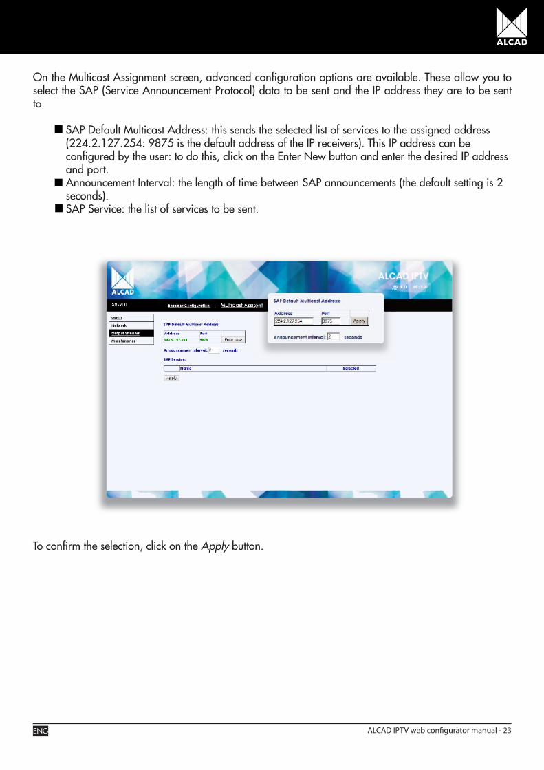
On the Multicast Assignment screen, advanced configuration options are available. These allow you to select the SAP (Service Announcement Protocol) data to be sent and the IP address they are to be sent to. SAP Default Multicast Address: this sends the selected list of services to the assigned address (224.2.127.254: 9875 is the default address of the IP receivers). This IP address can be configured by the user: to do this, click on the Enter New button and enter the desired IP address and port. Announcement Interval: the length of time between SAP announcements (the default setting is 2 seconds). SAP Service: the list of services to be sent.
To confirm the selection, click on the Apply button.
ENG ALCAD IPTV web configurator manual - 23

Maintenance
Maintenance and adjustment of the SV module.
Streaming Control
This is used to control the status of the SV module. Two states are possible: Streaming (i.e. sending data streams via the RJ-45 outlet) or Stopped (i.e. not sending any data streams).
Streamer: to turn the SV module on or off, press Start or Stop. Streamer Status: shows the operating status of the SV module.
ENG24 - ALCAD IPTV web configurator manual
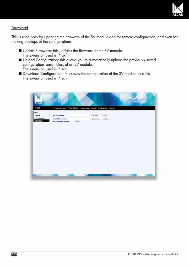
Download
This is used both for updating the firmware of the SV module and for remote configuration; and even for making backups of the configurations.
Update Firmware: this updates the firmware of the SV module. The extension used is: *.axf Upload Configuration: this allows you to automatically upload the previously saved configuration parameters of an SV module. The extension used is: *.scn Download Configuration: this saves the configuration of the SV module as a file. The extension used is: *.scn
ENG ALCAD IPTV web configurator manual - 25
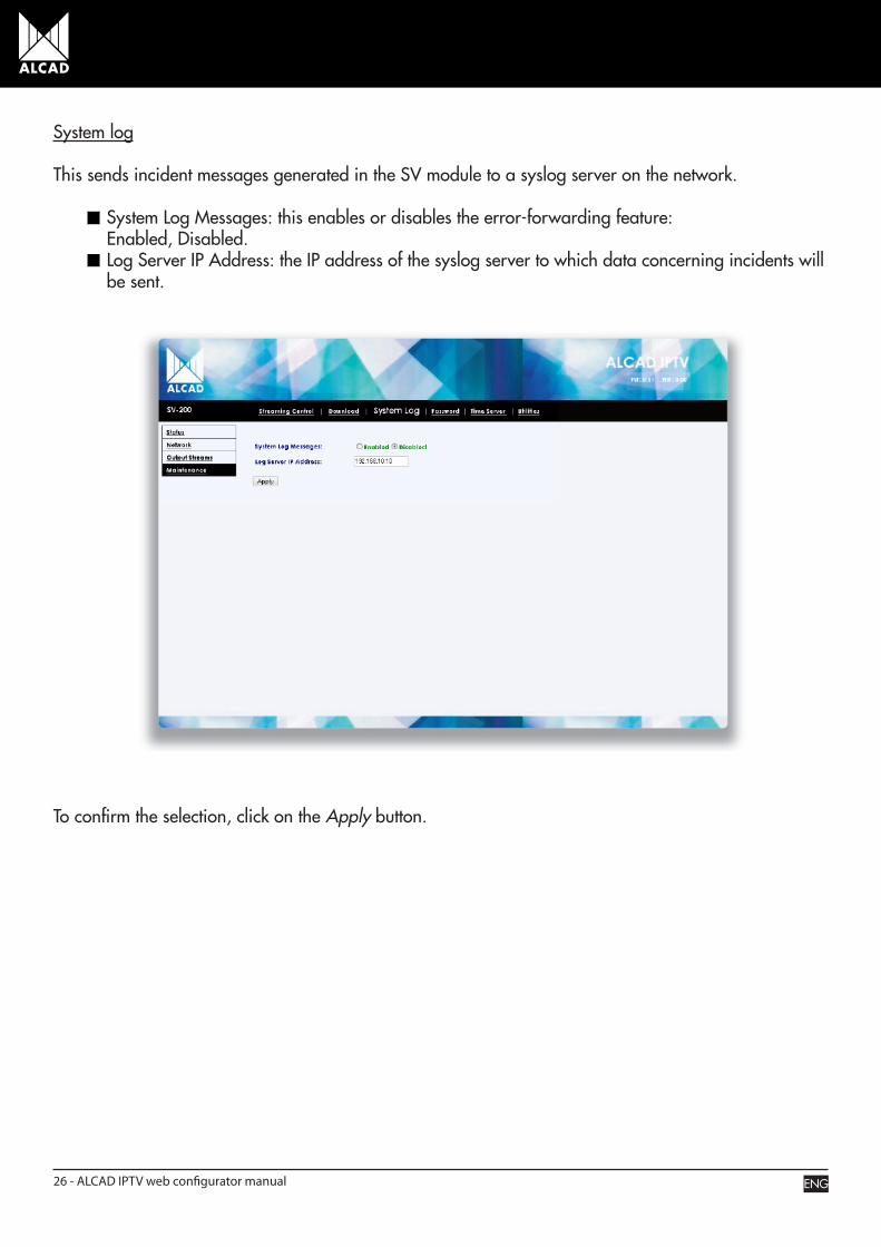
System log
This sends incident messages generated in the SV module to a syslog server on the network.
System Log Messages: this enables or disables the error-forwarding feature: Enabled, Disabled. Log Server IP Address: the IP address of the syslog server to which data concerning incidents will be sent.
To confirm the selection, click on the Apply button.
ENG26 - ALCAD IPTV web configurator manual
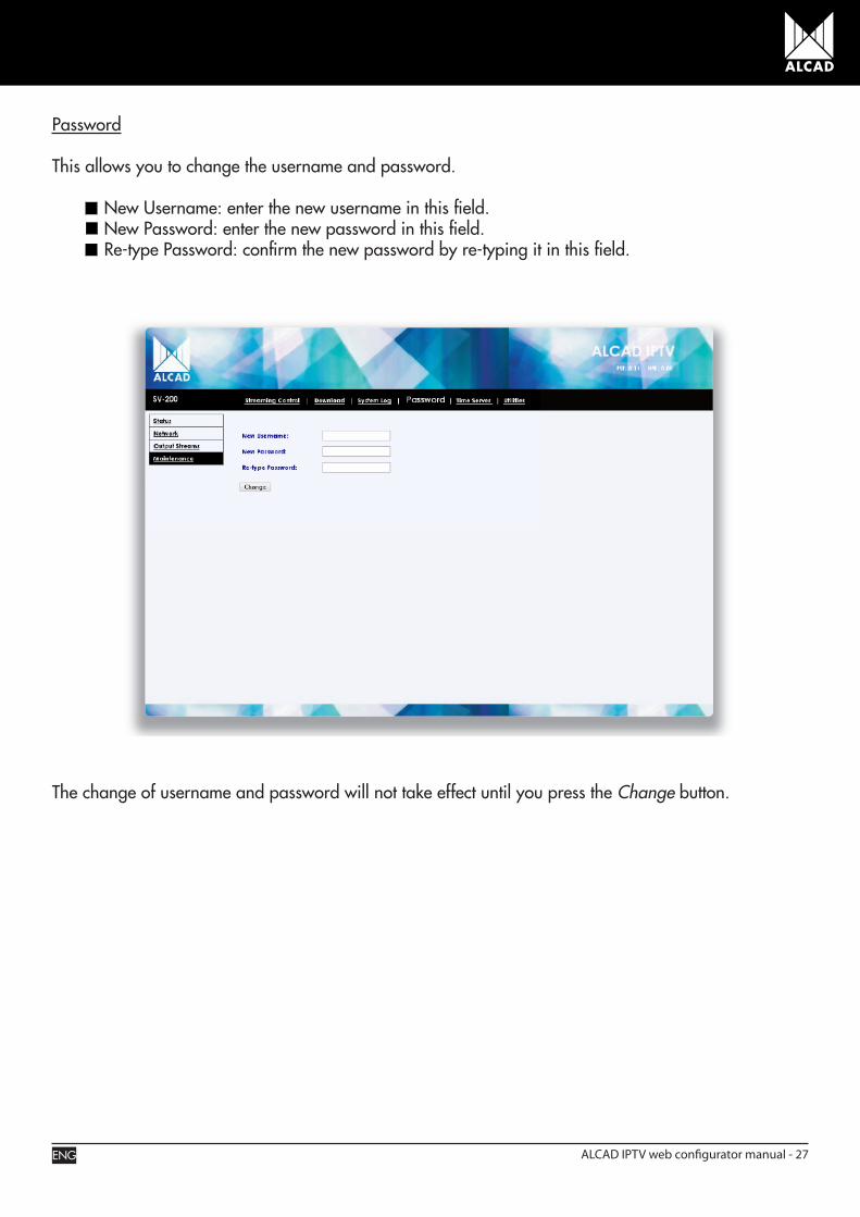
Password
This allows you to change the username and password.
New Username: enter the new username in this field. New Password: enter the new password in this field. Re-type Password: confirm the new password by re-typing it in this field.
The change of username and password will not take effect until you press the Change button.
ENG ALCAD IPTV web configurator manual - 27
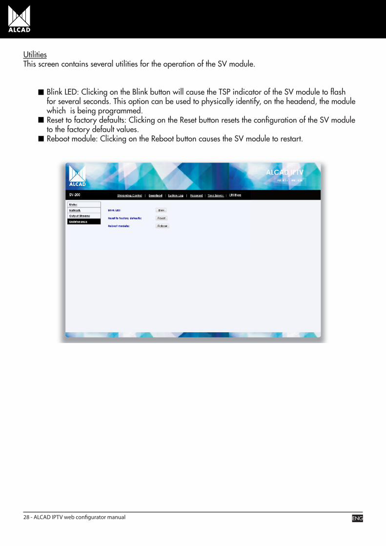
UtilitiesThis screen contains several utilities for the operation of the SV module.
Blink LED: Clicking on the Blink button will cause the TSP indicator of the SV module to flash for several seconds. This option can be used to physically identify, on the headend, the module which is being programmed. Reset to factory defaults: Clicking on the Reset button resets the configuration of the SV module to the factory default values. Reboot module: Clicking on the Reboot button causes the SV module to restart.
ENG28 - ALCAD IPTV web configurator manual
EXAMPLE OF CONFIGURATION AND OPERATION
When the equipment has been connected, the SV modules must be programmed on-line using the graphical environment described in the preceding pages. So far, we have explained all the possible configuration options. Now, as an example, we shall consider the programming of equipment consisting of 8 modules of the 915-SV series.
FACTORY NETWORK CONFIGURATION OF THE MODULES
Configuration type: Static IP IP address: 192.168.10.100 Subnet mask: 255.255.255.0
Default Gateway: 192.168.10.1
DESIRED NETWORK CONFIGURATION
Configuration type: Static IP IP address: 192.168.23.2 – 192.168.23.10
Subnet mask: 255.255.255.0 Default Gateway: 192.168.23.1
MULTICAST CONFIGURATION
Multicast Base Address: 230.40.50.60 Port 1234Differentiated Service: AF33-Highest Priority
Stream Payload Format: UDP TTL: 1
ENG ALCAD IPTV web configurator manual - 29
1
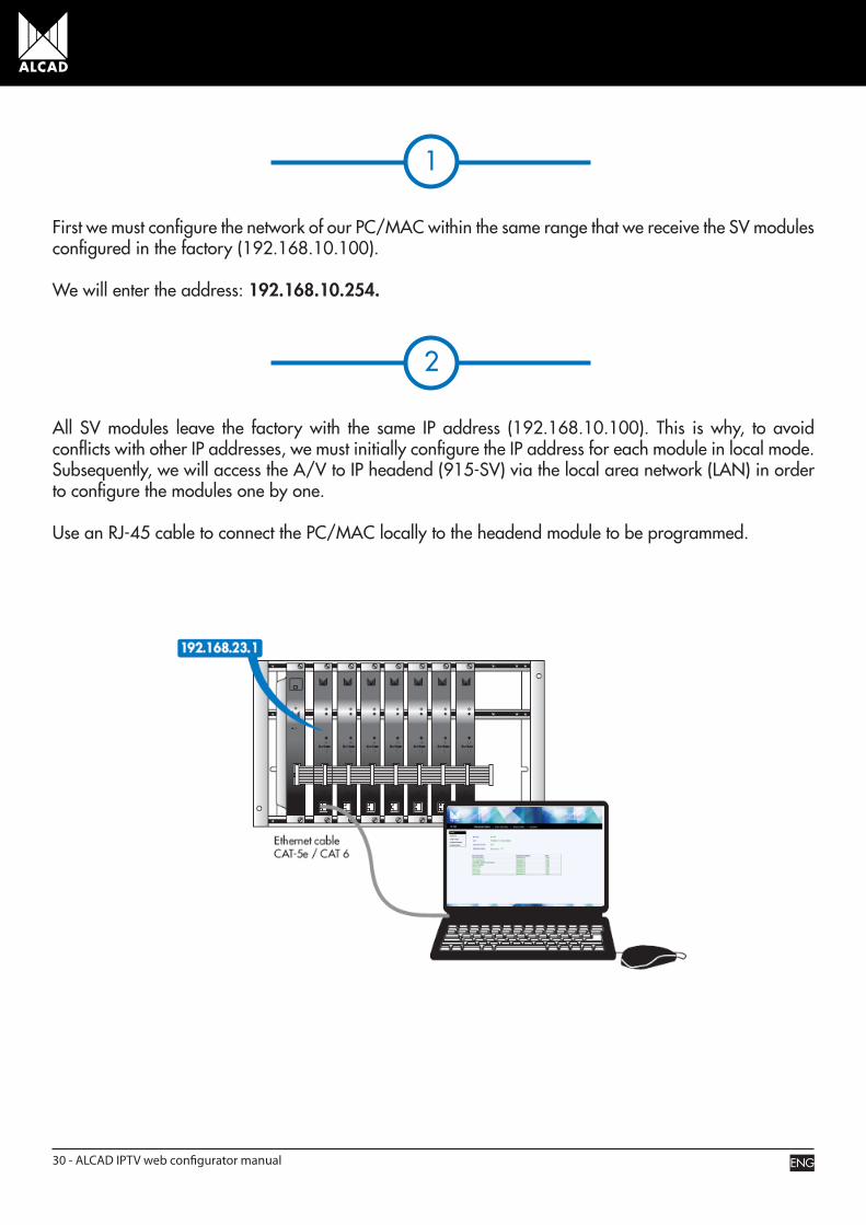
First we must configure the network of our PC/MAC within the same range that we receive the SV modules configured in the factory (192.168.10.100).
We will enter the address: 192.168.10.254.
2
All SV modules leave the factory with the same IP address (192.168.10.100). This is why, to avoid conflicts with other IP addresses, we must initially configure the IP address for each module in local mode. Subsequently, we will access the A/V to IP headend (915-SV) via the local area network (LAN) in order to configure the modules one by one.
Use an RJ-45 cable to connect the PC/MAC locally to the headend module to be programmed.
ENG30 - ALCAD IPTV web configurator manual
3
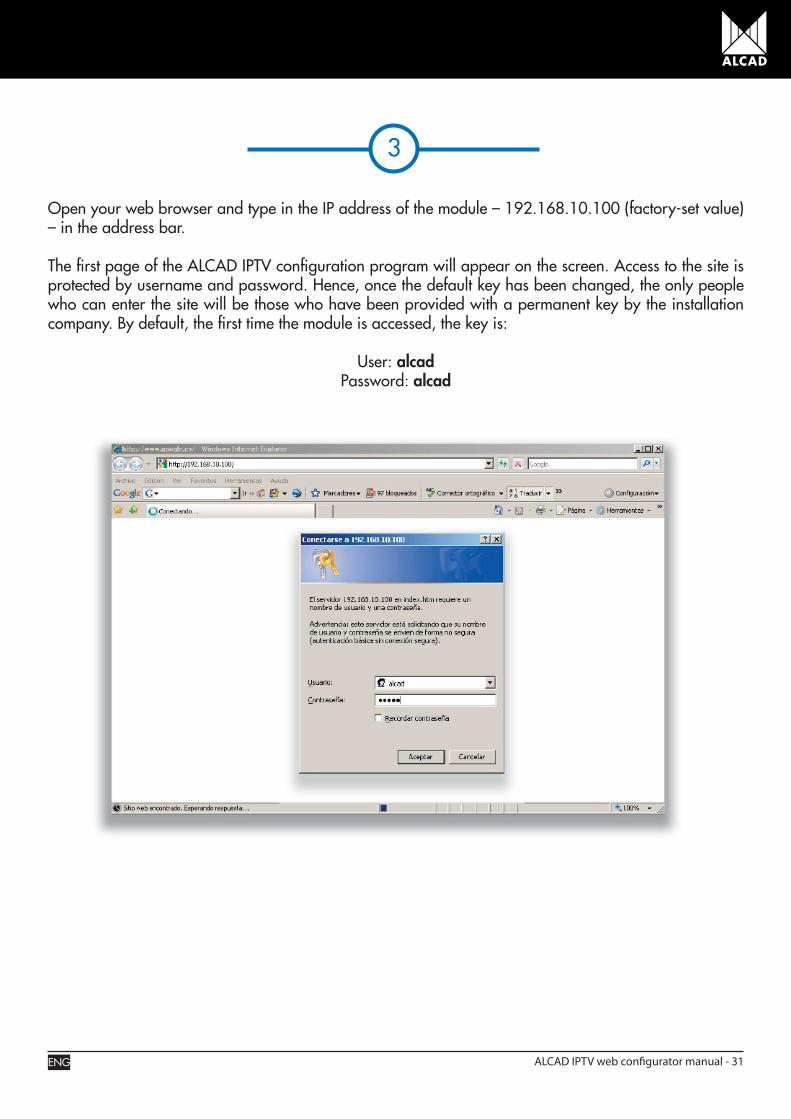
Open your web browser and type in the IP address of the module – 192.168.10.100 (factory-set value) – in the address bar.
The first page of the ALCAD IPTV configuration program will appear on the screen. Access to the site is protected by username and password. Hence, once the default key has been changed, the only people who can enter the site will be those who have been provided with a permanent key by the installation company. By default, the first time the module is accessed, the key is:
User: alcad Password: alcad
ENG ALCAD IPTV web configurator manual - 31
4
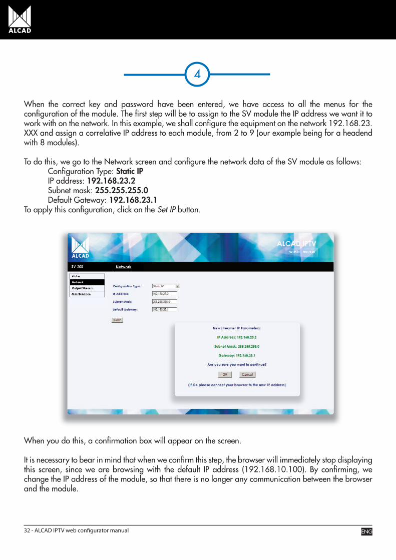
When the correct key and password have been entered, we have access to all the menus for the configuration of the module. The first step will be to assign to the SV module the IP address we want it to work with on the network. In this example, we shall configure the equipment on the network 192.168.23.XXX and assign a correlative IP address to each module, from 2 to 9 (our example being for a headend with 8 modules).
To do this, we go to the Network screen and configure the network data of the SV module as follows: Configuration Type: Static IP IP address: 192.168.23.2 Subnet mask: 255.255.255.0 Default Gateway: 192.168.23.1 To apply this configuration, click on the Set IP button.
When you do this, a confirmation box will appear on the screen.
It is necessary to bear in mind that when we confirm this step, the browser will immediately stop displaying this screen, since we are browsing with the default IP address (192.168.10.100). By confirming, we change the IP address of the module, so that there is no longer any communication between the browser and the module.
ENG32 - ALCAD IPTV web configurator manual

5
After configuring the IP address of the first module, we repeat the process from step 2 to step 4 with all the modules of the headend, assigning to each its appropriate IP address. In this way, we will have all the modules configured on the same network but with different IP addresses.
We can now connect all the SV modules to the switch without causing any problems with IP address conflicts. Now we connect the PC/MAC to the switch, configuring it on the same network as the modules and the switch itself, but with a different IP address.
We configure the IP of the PC/MAC with the following data:
IP address: 192.168.23.254 Subnet mask: 255.255.255.0 Default gateway: 192.168.23.1
ENG ALCAD IPTV web configurator manual - 33

6
At this point, we can now configure the parameters of all the SV modules simply by entering the IP address of each module in turn in the address bar of the browser.
We will again be asked to enter the username and password in order to have access to the program (by default: username = alcad; password = alcad). We type in this information and start the configuration.
First comes the configuration of the encoders of the composite video (A/V) signal which we wish to broadcast. To configure this, we click on Output Streams and select the Encoder Configuration tab.
We begin by activating the encoders to which we have connected the devices emitting the A/V signal (cameras, playback devices, etc.).
Next we enter the desired configuration parameters for the output streams.
When all the data has been entered, we click on the Apply button.
To show the advanced configuration screen, we click on the Select Params button.
ENG34 - ALCAD IPTV web configurator manual
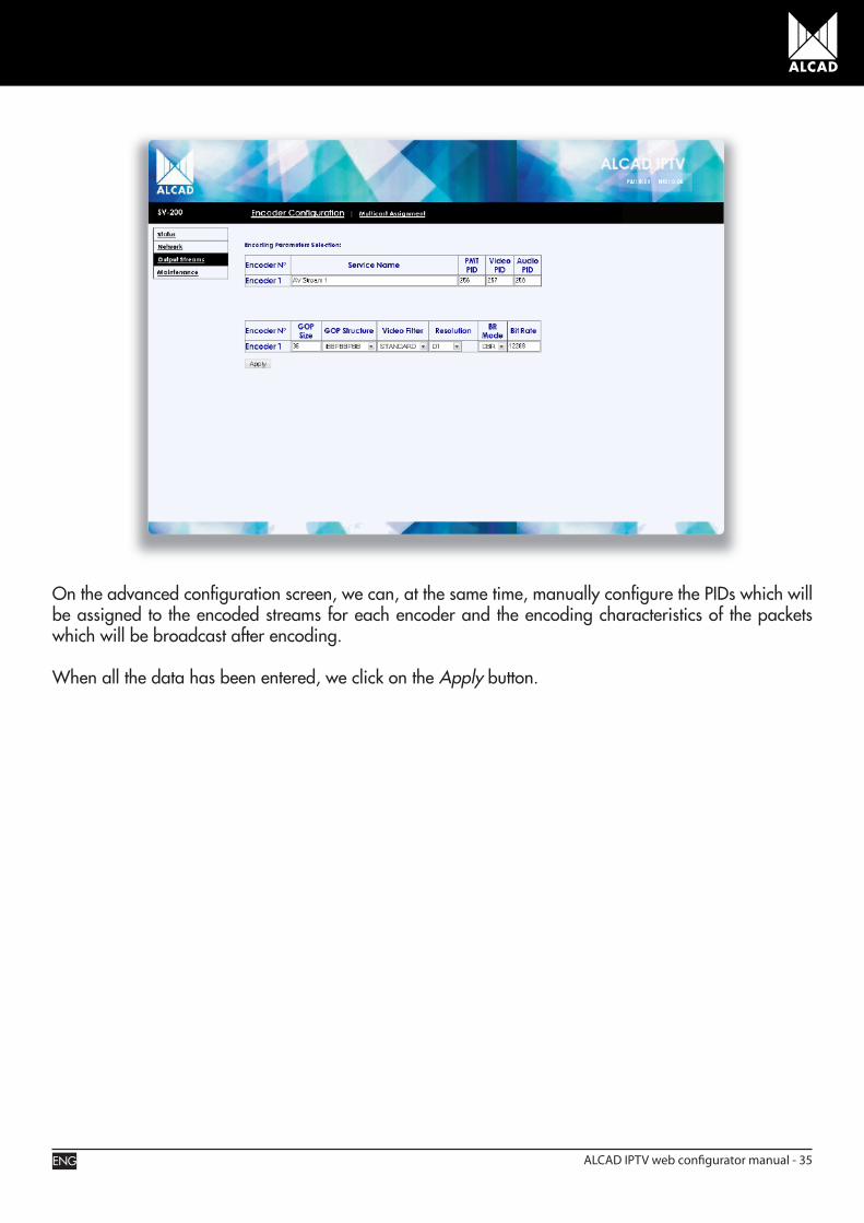
On the advanced configuration screen, we can, at the same time, manually configure the PIDs which will be assigned to the encoded streams for each encoder and the encoding characteristics of the packets which will be broadcast after encoding.
When all the data has been entered, we click on the Apply button.
ENG ALCAD IPTV web configurator manual - 35
7
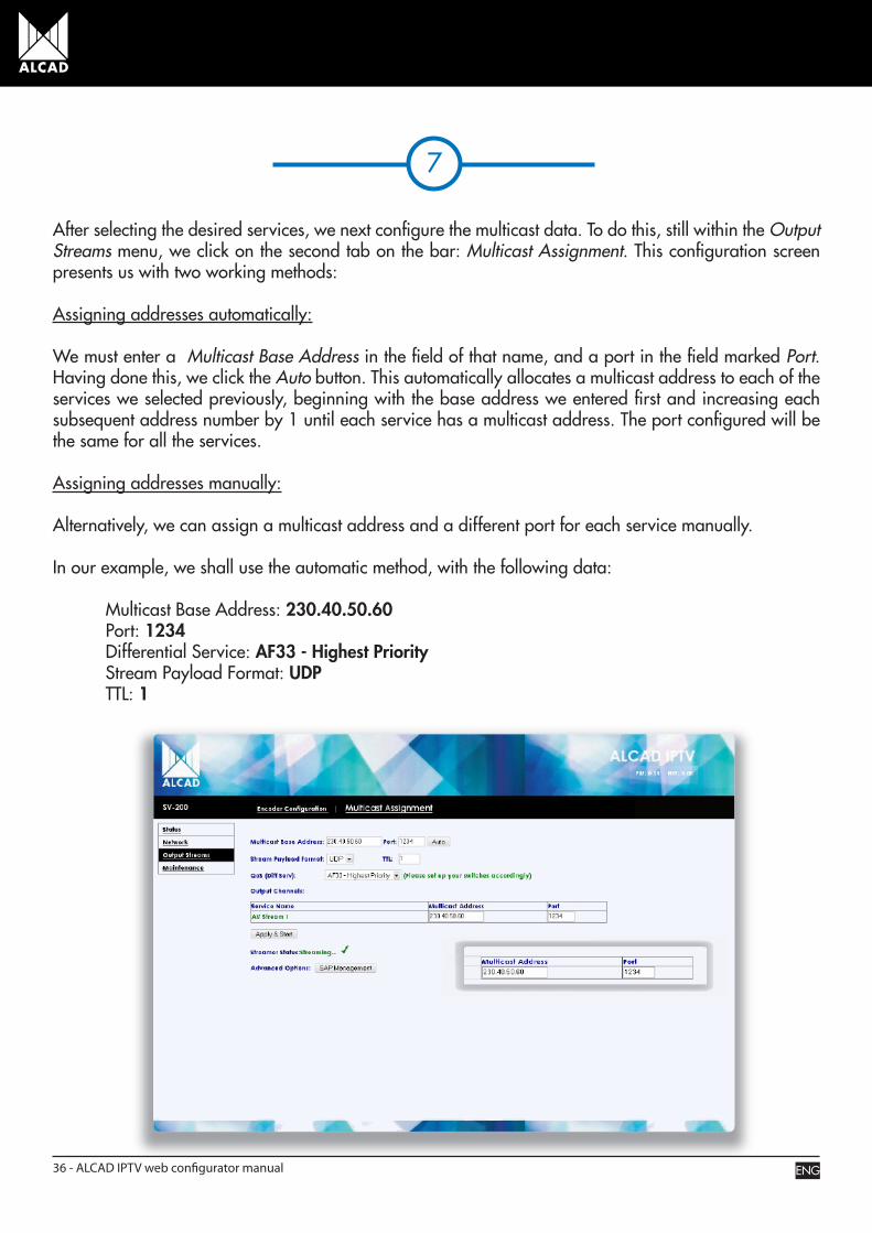
After selecting the desired services, we next configure the multicast data. To do this, still within the Output Streams menu, we click on the second tab on the bar: Multicast Assignment. This configuration screen presents us with two working methods:
Assigning addresses automatically:
We must enter a Multicast Base Address in the field of that name, and a port in the field marked Port. Having done this, we click the Auto button. This automatically allocates a multicast address to each of the services we selected previously, beginning with the base address we entered first and increasing each subsequent address number by 1 until each service has a multicast address. The port configured will be the same for all the services.
Assigning addresses manually:
Alternatively, we can assign a multicast address and a different port for each service manually.
In our example, we shall use the automatic method, with the following data:
Multicast Base Address: 230.40.50.60 Port: 1234 Differential Service: AF33 - Highest Priority Stream Payload Format: UDP TTL: 1
ENG36 - ALCAD IPTV web configurator manual
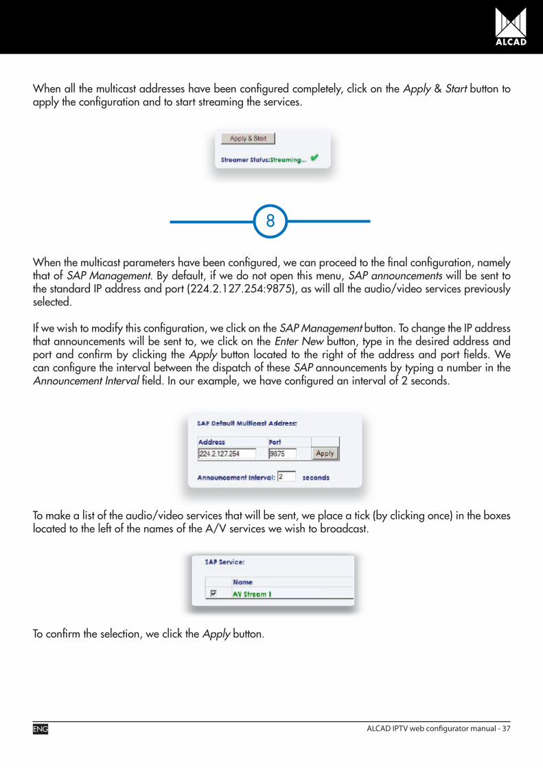
When all the multicast addresses have been configured completely, click on the Apply & Start button to apply the configuration and to start streaming the services.
8
When the multicast parameters have been configured, we can proceed to the final configuration, namely that of SAP Management. By default, if we do not open this menu, SAP announcements will be sent to the standard IP address and port (224.2.127.254:9875), as will all the audio/video services previously selected.
If we wish to modify this configuration, we click on the SAP Management button. To change the IP address that announcements will be sent to, we click on the Enter New button, type in the desired address and port and confirm by clicking the Apply button located to the right of the address and port fields. We can configure the interval between the dispatch of these SAP announcements by typing a number in the Announcement Interval field. In our example, we have configured an interval of 2 seconds.
To make a list of the audio/video services that will be sent, we place a tick (by clicking once) in the boxes located to the left of the names of the A/V services we wish to broadcast.
To confirm the selection, we click the Apply button.
ENG ALCAD IPTV web configurator manual - 37

9
At this point, the module is fully configured and operating correctly, broadcasting the desired services via its RJ-45 output.
To configure the remaining SV modules, repeat steps 5 through 8 for each module. The headend will then be ready to be connected to the rest of the network via the different switches. To check on the configuration of any of the modules, we simply go to the Status menu.
ENG38 - ALCAD IPTV web configurator manual

TROUBLE SHOOTING
P = PROBLEM C = CAUSE S = SOLUTION
P. General problems, some indicators do not light up.C. The streaming module has not been programmed correctly.S. Check the data used to program the SV module with the ALCAD IPTV Web Configurator, in the Status menu.
P. The activation indicator of encoder ENC 1 and/or encoder ENC 2 does not light up.C. The encoder associated to the indicator is deactivated. S. Use the ALCAD IPTV software to ensure that the encoder is activated: OUTPUT STREAMS menu, Encoder Configuration tab.
P. The ENC 1 and ENC 2 indicators are lit up but the picture is black. C. There is no input audio-video signal. S. Ensure that the originating devices of the composite video signal (cameras, playback devices, etc.) are correctly connected to the appropriate SV-200 module.
P. The ENC 1 and ENC 2 indicators are lit up, the originating devices of the A/V signal are connected correctly, but the picture is black.C. There is no audio/video input signal. S. Check that the originating devices of the composite video signal (cameras, playback devices, etc.) are switched on and are functioning correctly.
P. The orange Ethernet connection indicator does not light up.C. You are not connected to any network. S. Check that the connection of the network cable is correct.
P. The indicators of the RJ-45 connector (LINK and DATA) do not blink. C. The SV module is not configured or streaming is stopped. S. Configure all the parameters of the module and click on the Start button to begin streaming.
P. The green indicator showing Ethernet activity is blinking although the module has not yet been configured. C. The module is receiving data traffic from some other source (e.g. another streamer or PC) and is connected to a switch that does not have IGMP or does not have this function enabled. S. Check that the switch supports the IGMP protocol and that this function is enabled.
ENG ALCAD IPTV web configurator manual - 39

2635
140.
01