Embed Size (px)
Citation preview
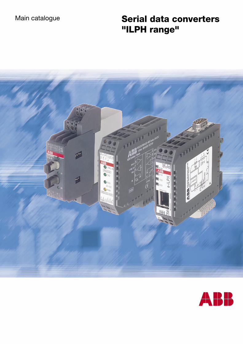
Main catalogue Serial data converters "ILPH range"

1N07001 060209
RS-232 RS-485
RS-232 RS-232RS-422
RS-422 RS-422
RS-422
RS-232
RS-232 RS-232 RS-232 RS-232
RS-232 RS-23215 m
max.
1.2 km
max.
15 m
max.
1.2 km
max.
TCPRS-232 RS-485
Modbus / RTUModbus / TCP
1SNC 116 001 C0202
Serial data converters
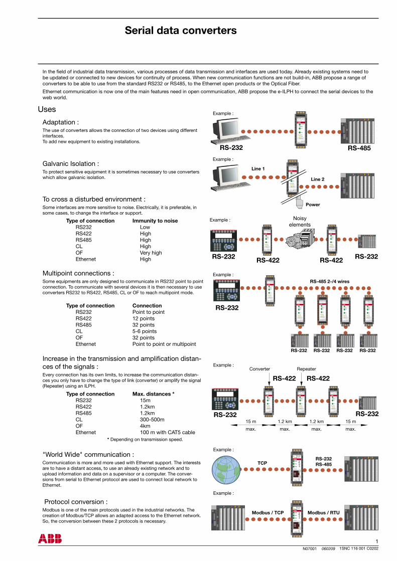
In the field of industrial data transmission, various processes of data transmission and interfaces are used today. Already existing systems need to be updated or connected to new devices for continuity of process. When new communication functions are not build-in, ABB propose a range of converters to be able to use from the standard RS232 or RS485, to the Ethernet open products or the Optical Fiber.
Ethernet communication is now one of the main features need in open communication, ABB propose the e-ILPH to connect the serial devices to the web world.
Uses
Adaptation :The use of converters allows the connection of two devices using different interfaces. To add new equipment to existing installations.
Galvanic Isolation :To protect sensitive equipment it is sometimes necessary to use converters which allow galvanic isolation.
Type of connection Immunity to noise RS232 Low RS422 High RS485 High CL High OF Very high Ethernet High
To cross a disturbed environment :Some interfaces are more sensitive to noise. Electrically, it is preferable, in some cases, to change the interface or support.
Multipoint connections :Some equipments are only designed to communicate in RS232 point to point connection. To communicate with several devices it is then necessary to use converters RS232 to RS422, RS485, CL or OF to reach multipoint mode.
Type of connection Connection RS232 Point to point RS422 12 points RS485 32 points CL 5-6 points OF 32 points Ethernet Point to point or multipoint
Type of connection Max. distances * RS232 15m RS422 1.2km RS485 1.2km CL 300-500m OF 4km Ethernet 100 m with CAT5 cable
Increase in the transmission and amplification distan-ces of the signals :Every connection has its own limits, to increase the communication distan-ces you only have to change the type of link (converter) or amplify the signal (Repeater) using an ILPH.
* Depending on transmission speed.
Example :
Example :
Line 1
Line 2
Power
Converter Repeater
Example :
Example :
Example :
Noisyelements
RS-485 2-/4 wires
"World Wide" communication :Communication is more and more used with Ethernet support. The interests are to have a distant access, to use an already existing network and to upload information and data on a supervisor or a computer. The conver-sions from serial to Ethernet protocol are used to connect local network to Ethernet.
Protocol conversion :Modbus is one of the main protocols used in the industrial networks. The creation of Modbus/TCP allows an adapted access to the Ethernet network. So, the conversion between these 2 protocols is necessary.
Example :
Example :
2N07002 060209
• • • • • • • • • • • • • • • • • • • • • • • • • • • • • • • • • • • •
1SNA 684 234 R2000
1SNA 684 244 R0200
1SNA 684 231 R2500
1SNA 684 233 R2700
1SNA 684 333 R2300
1SNA 684 334 R2400
1SNA 684 202 R0100
1SNA 684 236 R2200
1SNA 684 237 R2300
1SNA 684 238 R0400
1SNA 684 239 R0500
1SNA 684 212 R2200
1SNA 684 232 R2600
1SNA 684 246 R0400
1SNA 684 247 R0500
1SNA 684 248 R1600
1SNA 684 249 R1700
1SNA 684 252 R0200
RS232
RS422 / RS485
RS485
RS232 / RS485
RS2
32
RS4
22 /
RS4
85
24 V
DC
24-4
8 V
DC
110-
240
V AC
24-4
2 V
AC/D
C
Ethe
rnet
10-3
4 VDC
, 10-
24 V
AC
1SNC 116 001 C0202
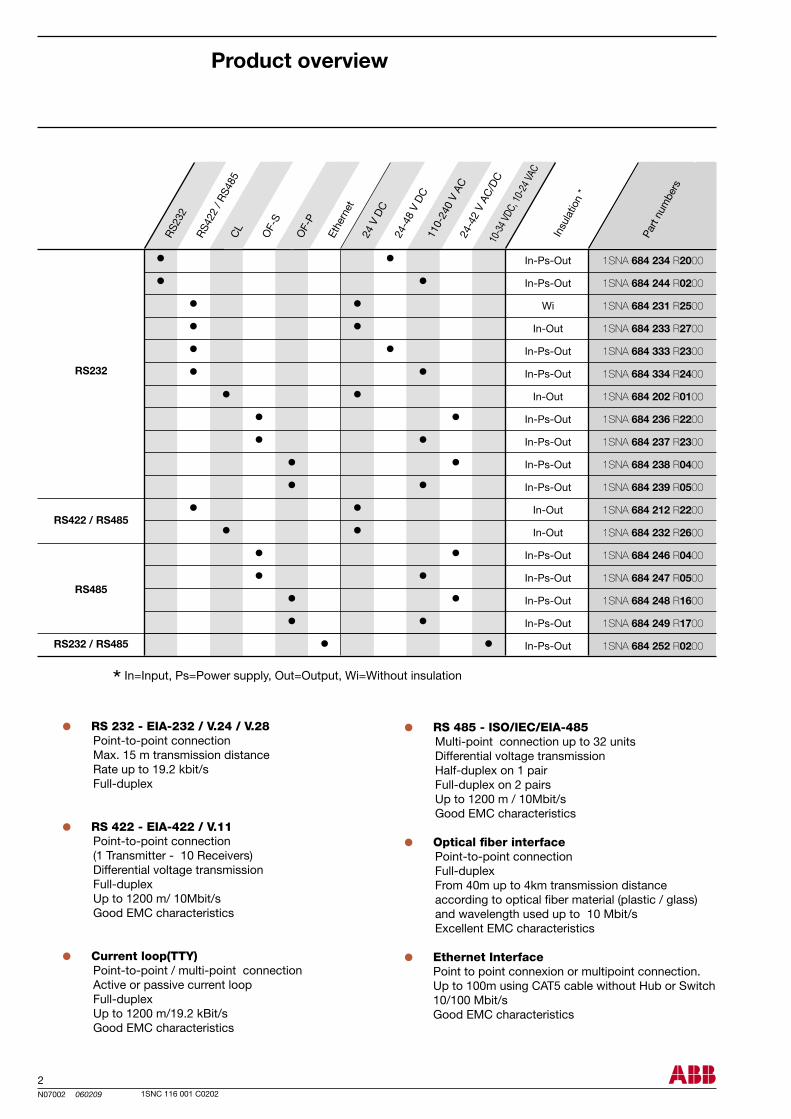
RS 232 - EIA-232 / V.24 / V.28 Point-to-point connection Max. 15 m transmission distance Rate up to 19.2 kbit/s Full-duplex
RS 422 - EIA-422 / V.11 Point-to-point connection (1 Transmitter - 10 Receivers) Differential voltage transmission Full-duplex Up to 1200 m/ 10Mbit/s Good EMC characteristics
Current loop(TTY) Point-to-point / multi-point connection Active or passive current loop Full-duplex Up to 1200 m/19.2 kBit/s Good EMC characteristics
RS 485 - ISO/IEC/EIA-485 Multi-point connection up to 32 units Differential voltage transmission Half-duplex on 1 pair Full-duplex on 2 pairs Up to 1200 m / 10Mbit/s Good EMC characteristics
Optical fiber interface Point-to-point connection Full-duplex From 40m up to 4km transmission distance according to optical fiber material (plastic / glass) and wavelength used up to 10 Mbit/s Excellent EMC characteristics
Ethernet Interface Point to point connexion or multipoint connection. Up to 100m using CAT5 cable without Hub or Switch 10/100 Mbit/s Good EMC characteristics
In-Ps-Out
In-Ps-Out
Wi
In-Out
In-Ps-Out
In-Ps-Out
In-Out
In-Ps-Out
In-Ps-Out
In-Ps-Out
In-Ps-Out
In-Out
In-Out
In-Ps-Out
In-Ps-Out
In-Ps-Out
In-Ps-Out
In-Ps-Out
Insu
latio
n *
Part
num
bers
* In=Input, Ps=Power supply, Out=Output, Wi=Without insulation
CL
OF-
S
OF-
P
Product overview
3N07012 060209
ILPH RS 232-RS 485 / Ethernet 1 0,12
ILPH RS 232 - 485 / Ethernet
+24V0V
24V
TXTX
GND
RXRX
B1+
B2-
M
JH
G
ML
K
DE
A
GND
RX
TX
Ethernet
LINK
TXD
RXD
e-ILPH
SPEE
D
PWR
ACTIVITY
M LK
JH
G
ML
K
43
21
ON
43
21
ON56
78
KL
DE A
1SNC 116 001 C0202
Serial data converters"ILPH Range"
Power supply 1 Voltage 10...34 V DC, 10...24 V AC Voltage tolerance -10%, +10% Consumption 2 W max Connections coding screw removable connector 0 to 2,5 mm² (22-14 AWG)
Power supply 2 Voltage 10...34 V DC Voltage tolerance -10%, +10% Consumption 2 W max Connections screw connector (AWG 20)
Serial link 1 : RS 232 EIA RS 232 Overvoltage protection integrated Baud rate / Transmission distance max. 115,2 kbits/s / max. 15 m Connections 2,5 mm² screw connector (AWG 20) or male SubD 9 points
Serial link 2 : RS 485 EIA RS 485 Overvoltage protection integrated Line polarization integrated End line resistance integrated Baud rate / Transmission distance max. 115,2 kbits/s / max. 1200 m Connections coding screw removable connector 0 to 2,5 mm² (22-14 AWG)
Ethernet link Overvoltage protection integrated Baud rate / Transmission distance 10-100 Mbits/s / max. 100 m without Hub or Switch with CAT5 cable Connections RJ45 connector
Traffic indication Voltage 1 yellow LED Status of signal 3 green LED (RxD, TxD, LINK), 2 amber or green LED (Speed, Activity)
EMC behavior Electrostatic discharge EN 61000-4-2 Radiated electromagnetic field EN 61000-4-3 Burst EN 61000-4-4 Surge EN 61000-4-5 Electromagnetic compatibility EN 55022
Other characteristics Galvanic isolation between serial link / power supply / Ethernet link 750 VDC / 1500 VAC Configuration of the operating mode using internal switches or/and software (TELNET or HYPERTERMINAL) Operating temperature 0°C ... +60°C Storage temperature -20°C ... +70°C Mounting any required DIN rail fixing (EN 50002) snap-on mounting Wire size 2,5 mm² / stranded with ferrule, 4 mm² solid Dimensions (W x D x H) 94 x 22,5 x 100 mm Weight 120 g
Serial data converter e-ILPH
Description Type Order P/N Packaging Weight kg
Technical data
Power supply
Power supply 2Power supply 1
center of rail
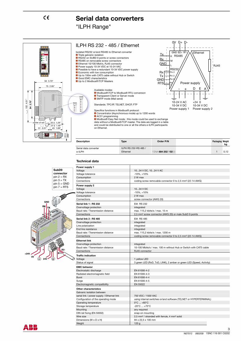
Isolated RS232 or/and RS485 to Ethernet converter Triple galvanic isolation RS232 on SUBD 9 points or screw connectors RS485 on removable screw connectors Ethernet 10/100 Mbit/s, RJ45 connector Power supply 10-34 VDC et 10-24 VAC Possible to have a redundant 10-34 VDC power supply Economic with low consumption Up to 100m with CAT5 cable without Hub or Switch Good EMC characteristics Up to 2 Modbus®\TCP Masters
Available modes: Modbus®\TCP to Modbus® RTU conversion Transparent Client or Server mode SMTP mode (Mail send)
Standards: TPC/IP, TELNET, DHCP, FTP
Specifics functions in Modbus® protocol: Concentrator (Asynchronous mode) up to 1200 words AC31 programming Modbus® Easy Net mode : this mode could be used to exchange data without a Modbus®/TCP master. The data are logged in a table and could be distributed to one or all the others e-ILPH participants on Ethernet.
SubD9 connector pin 2 = RXpin 3 = TXpin 5 = GNDpin 7 = RTS
1SNA 684 252 R0200
4N07003 060209
RRt E
R
E
R
E
Rt
Rt
Rt
R
E
ILPH RS 232 / RS 422-485 1 0,1
1SNC 116 001 C0202
Serial data converters"ILPH Range"
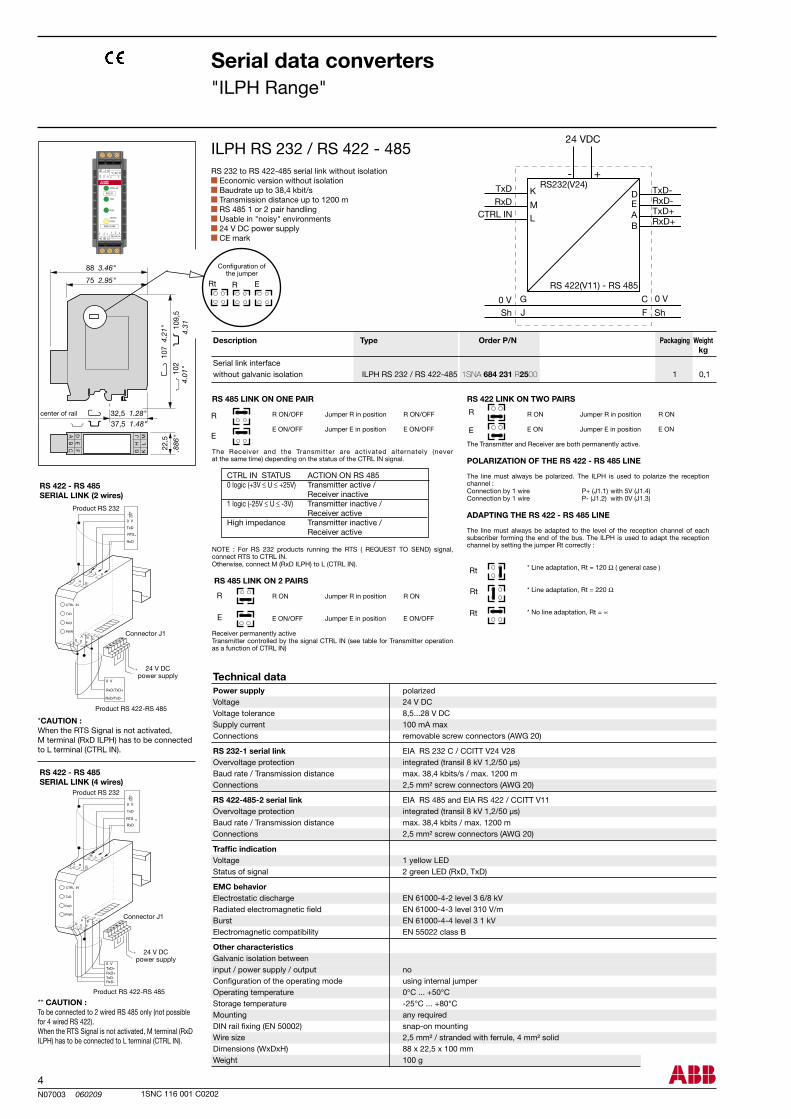
ILPH RS 232 / RS 422 - 485RS 232 to RS 422-485 serial link without isolation
Economic version without isolation Baudrate up to 38,4 kbit/s Transmission distance up to 1200 m RS 485 1 or 2 pair handling Usable in "noisy" environments 24 V DC power supply CE mark
center of rail
Configuration ofthe jumper
Power supply polarized Voltage 24 V DC Voltage tolerance 8,5...28 V DC Supply current 100 mA max Connections removable screw connectors (AWG 20)
RS 232-1 serial link EIA RS 232 C / CCITT V24 V28 Overvoltage protection integrated (transil 8 kV 1,2/50 µs) Baud rate / Transmission distance max. 38,4 kbits/s / max. 1200 m Connections 2,5 mm² screw connectors (AWG 20)
RS 422-485-2 serial link EIA RS 485 and EIA RS 422 / CCITT V11 Overvoltage protection integrated (transil 8 kV 1,2/50 µs) Baud rate / Transmission distance max. 38,4 kbits / max. 1200 m Connections 2,5 mm² screw connectors (AWG 20)
Traffic indication Voltage 1 yellow LED Status of signal 2 green LED (RxD, TxD)
EMC behavior Electrostatic discharge EN 61000-4-2 level 3 6/8 kV Radiated electromagnetic field EN 61000-4-3 level 310 V/m Burst EN 61000-4-4 level 3 1 kV Electromagnetic compatibility EN 55022 class B
Other characteristics Galvanic isolation between input / power supply / output no Configuration of the operating mode using internal jumper Operating temperature 0°C ... +50°C Storage temperature -25°C ... +80°C Mounting any required DIN rail fixing (EN 50002) snap-on mounting Wire size 2,5 mm² / stranded with ferrule, 4 mm² solid Dimensions (WxDxH) 88 x 22,5 x 100 mm Weight 100 g
*CAUTION : When the RTS Signal is not activated, M terminal (RxD ILPH) has to be connected to L terminal (CTRL IN).
RS 422 - RS 485SERIAL LINK (2 wires)
Product RS 232
Connector J1
24 V DCpower supply
Product RS 422-RS 485
** CAUTION :To be connected to 2 wired RS 485 only (not possible for 4 wired RS 422). When the RTS Signal is not activated, M terminal (RxD ILPH) has to be connected to L terminal (CTRL IN).
RS 422 - RS 485SERIAL LINK (4 wires)
Product RS 232
Connector J1
24 V DCpower supply
Product RS 422-RS 485
RS 485 LINK ON ONE PAIR
R ON/OFF Jumper R in position R ON/OFF
E ON/OFF Jumper E in position E ON/OFF
The Receiver and the Transmitter are activated alternately (never at the same time) depending on the status of the CTRL IN signal.
CTRL IN STATUS ACTION ON RS 485 0 logic (+3V ≤ U ≤ +25V) Transmitter active / Receiver inactive 1 logic (-25V ≤ U ≤ -3V) Transmitter inactive / Receiver active High impedance Transmitter inactive / Receiver active
NOTE : For RS 232 products running the RTS ( REQUEST TO SEND) signal, connect RTS to CTRL IN.Otherwise, connect M (RxD ILPH) to L (CTRL IN).
RS 485 LINK ON 2 PAIRS
R ON Jumper R in position R ON
E ON/OFF Jumper E in position E ON/OFF
Receiver permanently activeTransmitter controlled by the signal CTRL IN (see table for Transmitter operation as a function of CTRL IN)
RS 422 LINK ON TWO PAIRS
R ON Jumper R in position R ON
E ON Jumper E in position E ON
The Transmitter and Receiver are both permanently active.
POLARIZATION OF THE RS 422 - RS 485 LINE
The line must always be polarized. The ILPH is used to polarize the reception channel :Connection by 1 wire P+ (J1.1) with 5V (J1.4)Connection by 1 wire P- (J1.2) with 0V (J1.3)
ADAPTING THE RS 422 - RS 485 LINE
The line must always be adapted to the level of the reception channel of each subscriber forming the end of the bus. The ILPH is used to adapt the reception channel by setting the jumper Rt correctly :
* Line adaptation, Rt = 120 Ω ( general case )
* Line adaptation, Rt = 220 Ω
* No line adaptation, Rt = ∝
Serial link interface without galvanic isolation
Description Type Order P/N Packaging Weight kg
Technical data
1SNA 684 231 R2500
5N07004 060209
ILPH RS 232 / RS 422-485 1 0,1
R
Rt
E
R
E
R
E
R
E
Rt
Rt
Rt
ILPH RS 232 / RS 422 - 485
1SNC 116 001 C0202
Serial data converters"ILPH Range"
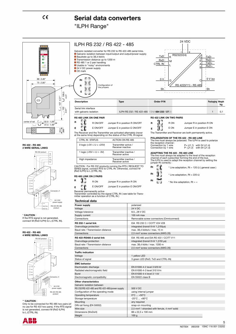
Galvanic isolated converter for RS 232 to RS 422-485 serial links. Galvanic isolation between input/output and output/power supply Baudrate up to 38,4 kbit/s Transmission distance up to 1200 m RS 485 1 or 2 pair handling Usable in "noisy" environments 24 V DC power supply CE mark
** CAUTION :Only to be connected for RS 485 two pairs (of no use for RS 422 two pairs). If the RTS signal is not generated, connect M (RxD ILPH) to L (CTRL IN).
* CAUTION : If the RTS signal is not generated, connect M (RxD ILPH) to L (CTRL IN).
RS 422 - RS 4852 WIRE SERIAL LINKS
RS 422 - RS 4854 WIRE SERIAL LINKS
Connector J1
24 V DCpower supply
RS 422-RS 485 product
RS 232 product
Connector J1
24 V DCpower supply
RS 422-RS 485 product
RS 232 product
Serial link interface with galvanic isolation
Configuration ofthe jumpers
center of rail
RS 422 LINK ON TWO PAIRS
R ON Jumper R in position R ON
E ON Jumper E in position E ON
The Transmitter and Receiver are both permanently active.
POLARIZATION OF THE RS 422 - RS 485 LINEThe line must always be polarized. The ILPH is used to polarize the reception channel :Connection by 1 wire P+ (J1.1) with 5V (J1.4)Connection by 1 wire P- (J1.2) with 0V (J1.3)
ADAPTING THE RS 422 - RS 485 LINEThe line must always be adapted to the level of the reception channel of each subscriber forming the end of the bus.The ILPH is used to adapt the reception channel by setting the jumper Rt correctly :
* Line adaptation, Rt = 120 Ω ( general case )
* Line adaptation, Rt = 220 Ω
* No line adaptation, Rt = ∝
RS 485 LINK ON ONE PAIR
R ON/OFF Jumper R in position R ON/OFF
E ON/OFF Jumper E in position E ON/OFF
The Receiver and the Transmitter are activated alternately (never at the same time) depending on the status of the CTRL IN signal.
CTRL IN STATUS ACTION ON RS 485
0 logic (+3V ≤ U ≤ +25V) Transmitter active / Receiver inactive
1 logic (-25V ≤ U ≤ -3V) Transmitter inactive / Receiver active
High impedance Transmitter inactive / Receiver active
CAUTION : For RS 232 products running the RTS ( REQUEST TO SEND) signal, connect RTS to CTRL IN. Otherwise, connect M (RxD ILPH) to L (CTRL IN).
RS 485 LINK ON 2 PAIRS
R ON Jumper R in position R ON E ON/OFF Jumper E in position E ON/OFF
Receiver permanently activeTransmitter controlled by the signal CTRL IN ( see table for Trans-mitter operation as a function of CTRL IN )
Technical dataPower supply polarized Voltage 24 V DC Voltage tolerance 8,5...28 V DC Supply current 100 mA max Connections Removable screw connectors (Omniconnect)
RS 232-1 serial link EIA RS 232 C / CCITT V24 V28 Overvoltage protection integrated (transil 8 kV 1,2/50µs) Baud rate / Transmission distance max. 38,4 kbits/s / max. 15 m Connections 2,5 mm² screw connectors (AWG 20)
RS 422-RS485-2 serial link EIA RS 485 and EIA RS 422 / CCITT V11 Overvoltage protection integrated (transil 8 kV 1,2/50 µs) Baud rate / Transmission distance max. 38,4 kbits / max. 1200 m Connections 2,5 mm² screw connectors (AWG 20)
Traffic indication Voltage 1 yellow LED Status of signal 3 green LED (RxD, TxD and CTRL-IN)
EMC behavior Electrostatic discharge EN 61000-4-2 level 3 6/8 kV Radiated electromagnetic field EN 61000-4-3 level 310 V/m Burst EN 61000-4-4 level 3 1 kV Electromagnetic compatibility EN 55022 class B
Other characteristics Galvanic isolation between RS 232/RS 422-485 and RS 422-485/power supply 500 V DC Configuration of the operating mode using internal jumper Operating temperature 0°C ... +50°C Storage temperature -25°C ... +80°C Mounting any required DIN rail fixing (EN 50002) snap-on mounting Wire size 2,5 mm² / stranded with ferrule, 4 mm² solid Dimensions (WxDxH) 88 x 22,5 x 100 mm Weight 100 g
Description Type Order P/N Packaging Weight kg
1SNA 684 233 R2700
6N07005 060209
ILPH RS 232 / RS 422-485 1 0,1 1 0,1
ILPH RS 232 / RS 422 - 485
1SNC 116 001 C0202
Serial data converters"ILPH Range"
RS 422 - RS 4852 WIRE SERIAL LINK
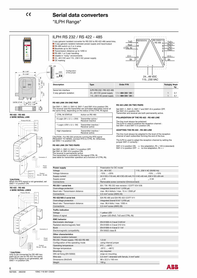
3 way galvanic isolated converter for RS 232 to RS 422-485 serial links. 3 way galvanic isolation between power supply and input/output RS 485 switch on 2 or 4 wires Baudrate up to 38,4 kbit/s Transmission distance up to 1200 m RS 485 1 or 2 pair handling Usable in "noisy" environments 24...48 V DC and 115...230 V AC power supply CE marking
**CAUTION :Only to be connected for RS 485 two pairs (of no use for RS 422 two pairs).If the RTS signal is not generated, set SW2-1 in position ON.
*CAUTION : When the RTS signal is not generated, set SW2-1 in position ON.
RS 422 - RS 4854 WIRE SERIAL LINKS
Connector J1
Powersupply
Product RS 232
Connector J1
Powersupply
ProductRS 422 - RS 485
Product RS 232
ProductRS 422 - RS 485
Power supply Polarization for DC model Voltage 24...48 V DC 115...230 V AC (50/60 Hz) Voltage tolerance -15% ... +20% -15% ... +15% Supply current 24 V DC<110 mA, 48 V DC<55 mA,115 V AC<40 mA, 230 V DC<26 mA Supply power ~ 3 W ~ 3 VA Connections Removable screw connector (Omniconnect)
RS 232-1 serial link EA / TIA RS 232 new revision / CCITT V24 V28 Overvoltage protection integrated (transil 8 kV 1,2/50 µs) Baud rate / Transmission distance max. 38,4 kbits/s / max. 15 m / 2500 pF Connections 2,5 mm² screw (AWG 20)
RS 422/485-2 serial link EIA RS 485 and EIA RS 422 CCITT V11 Overvoltage protection integrated (transil 8 kV 1,2/50 µs) Baud rate / Transmission distance max. 38,4 kbits / max. 1200 m Connections 2,5 mm² screw (AWG 20)
Traffic indication Voltage 1 yellow LED Status of signal 3 green LED (RxD, TxD and CTRL-IN)
EMC behavior Electrostatic discharge EN 61000-4-2 level 3 6/8 kV Radiated electromagnetic field EN 61000-4-3 level 310 V/m Burst EN 61000-4-4 level 3 1 kV Electromagnetic compatibility EN 55022 class B
Other characteristics Galvanic isolation between RS 232 / Power supply / RS 422-RS 485 1,5 kV Configuration of the operating mode using internal jumper Operating temperature 0°C ... +50°C Storage temperature -25°C ... +80°C Mounting any required DIN rail fixing (EN 50002) snap-on mounting Wire size 2,5 mm² / stranded with ferrule, 4 mm² solid Dimensions (WxDxH) 88 x 22,5 x 100 mm Weight 100 g
RS 485 LINK ON ONE PAIR
Set SW1-1, SW1-3, SW1-6, SW1-7 and SW1-8 to position ON. The receiver and the transmitter are activated alternately (never at the same time), depending on the status of the CTRL IN signal.
CTRL IN STATUS Action on RS 485
0 Logic (3V ≤ U ≤ + 25V) Transmitter active / Receiver inactive
1 Logic (-25V ≤ U ≤ -3V) Transmitter inactive / Receiver active
High impedance Transmitter inactive / Receiver active
CAUTION : For RS 232 products running the RTS signal (REQUEST TO SEND), connect RTS to CTRL IN. Otherwise, set SW2-1 to position ON.
RS 485 LINK ON TWO PAIRS
Set SW1-1, SW1-3, SW1-7 in position OFF.Set SW1-6, SW1-8 in position ON.The receiver is permanently active.The transmitter is controlled by the signal CTRL IN (see table for transmitter operation as a fonction of CTRL IN).
RS 422 LINK ON TWO PAIRS
Set SW1-1, SW1-3, SW1-7 and SW1-8 in position OFF.Set SW1-6 in position ON.Transmitter and receiver are both permanently active.
POLARIZATION OF THE RS 422 - RS 485 LINE
The line must always be polarized. The ILPH is used to polarize the reception channel :Set SW1-4 and SW1-5 in position ON.
ADAPTING THE RS 422 - RS 485 LINE
The line must always be adapted to the level of the reception channel of each subscriber forming the end of the bus.
The ILPH is used to adapt the reception channel by setting the jumper SW1-2 correctly :
SW1-2 in position ON ⇒ line adaptation, Rt = 120 Ω (standard)SW1-2 in position OFF ⇒ no line adaptation, Rt = ∝
center of rail
Configurationof the jumper
Serial link interface 3 way galvanic isolation 24...48 V DC power supply 115...230 V AC power supply
Description Type Order P/N Packaging Weight kg
1SNA 684 333 R2300 1SNA 684 334 R2400
7N07006 060209
ILPH RS 232 / RS 232 1 0,1 1 0,1
ILPH RS 232 / RS 232
1SNC 116 001 C0202
Serial data converters"ILPH Range"
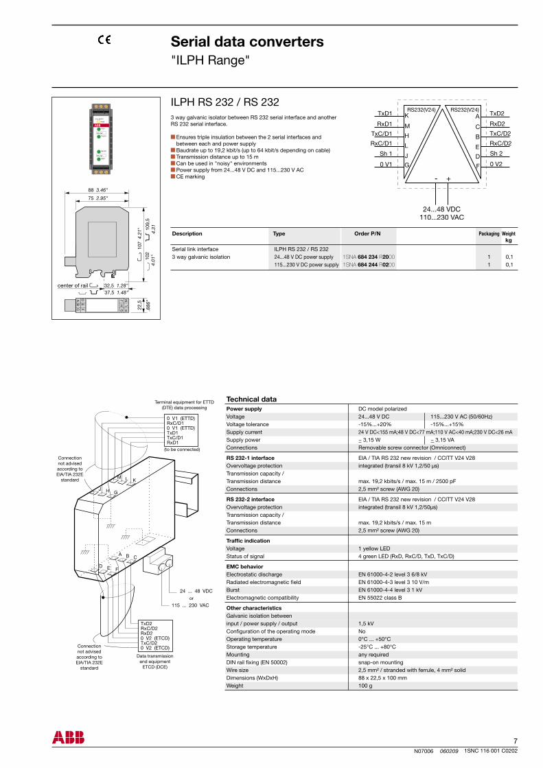
3 way galvanic isolator between RS 232 serial interface and another RS 232 serial interface.
Ensures triple insulation between the 2 serial interfaces and between each and power supply
Baudrate up to 19,2 kbit/s (up to 64 kbit/s depending on cable) Transmission distance up to 15 m Can be used in "noisy" environments Power supply from 24...48 V DC and 115...230 V AC CE marking
Power supply DC model polarized Voltage 24...48 V DC 115...230 V AC (50/60Hz) Voltage tolerance -15%...+20% -15%...+15% Supply current 24 V DC<155 mA;48 V DC<77 mA;110 V AC<40 mA;230 V DC<26 mA Supply power ~ 3,15 W ~ 3,15 VA Connections Removable screw connector (Omniconnect)
RS 232-1 interface EIA / TIA RS 232 new revision / CCITT V24 V28 Overvoltage protection integrated (transil 8 kV 1,2/50 µs) Transmission capacity / Transmission distance max. 19,2 kbits/s / max. 15 m / 2500 pF Connections 2,5 mm² screw (AWG 20)
RS 232-2 interface EIA / TIA RS 232 new revision / CCITT V24 V28 Overvoltage protection integrated (transil 8 kV 1,2/50µs) Transmission capacity / Transmission distance max. 19,2 kbits/s / max. 15 m Connections 2,5 mm² screw (AWG 20)
Traffic indication Voltage 1 yellow LED Status of signal 4 green LED (RxD, RxC/D, TxD, TxC/D)
EMC behavior Electrostatic discharge EN 61000-4-2 level 3 6/8 kV Radiated electromagnetic field EN 61000-4-3 level 3 10 V/m Burst EN 61000-4-4 level 3 1 kV Electromagnetic compatibility EN 55022 class B
Other characteristics Galvanic isolation between input / power supply / output 1,5 kV Configuration of the operating mode No Operating temperature 0°C ... +50°C Storage temperature -25°C ... +80°C Mounting any required DIN rail fixing (EN 50002) snap-on mounting Wire size 2,5 mm² / stranded with ferrule, 4 mm² solid Dimensions (WxDxH) 88 x 22,5 x 100 mm Weight 100 g
Connection not advised according to EIA/TIA 232E
standard
or
Connection not advised according to EIA/TIA 232E
standard
(to be connected)
Terminal equipment for ETTD (DTE) data processing
Data transmission end equipment
ETCD (DCE)
center of rail
Serial link interface 3 way galvanic isolation 24...48 V DC power supply 115...230 V DC power supply
Description Type Order P/N Packaging Weight kg
Technical data
1SNA 684 234 R2000 1SNA 684 244 R0200
8N07007 060209
ILPH RS 422 - 485 / RS 422 - 485 1 0,1
OFF
1 2 3 4
1 2 3 4 5 6
OFF
INT 3
INT 4
INT 3.1
INT 3.2
INT 4.1
INT 4.2
OFF
OFF
INT 3 1 2 3 4 5 6
INT 4 1 2 3 4
OFF
1 2 3 4
OFF
1 2 3 4 INT 1 INT 2
OFF
INT 1 1 2 3 4 1 2 3 4
INT 2
OFF
OFF
INT 4 1 2 3 4 5 6
OFF
INT 3 1 2 3 4
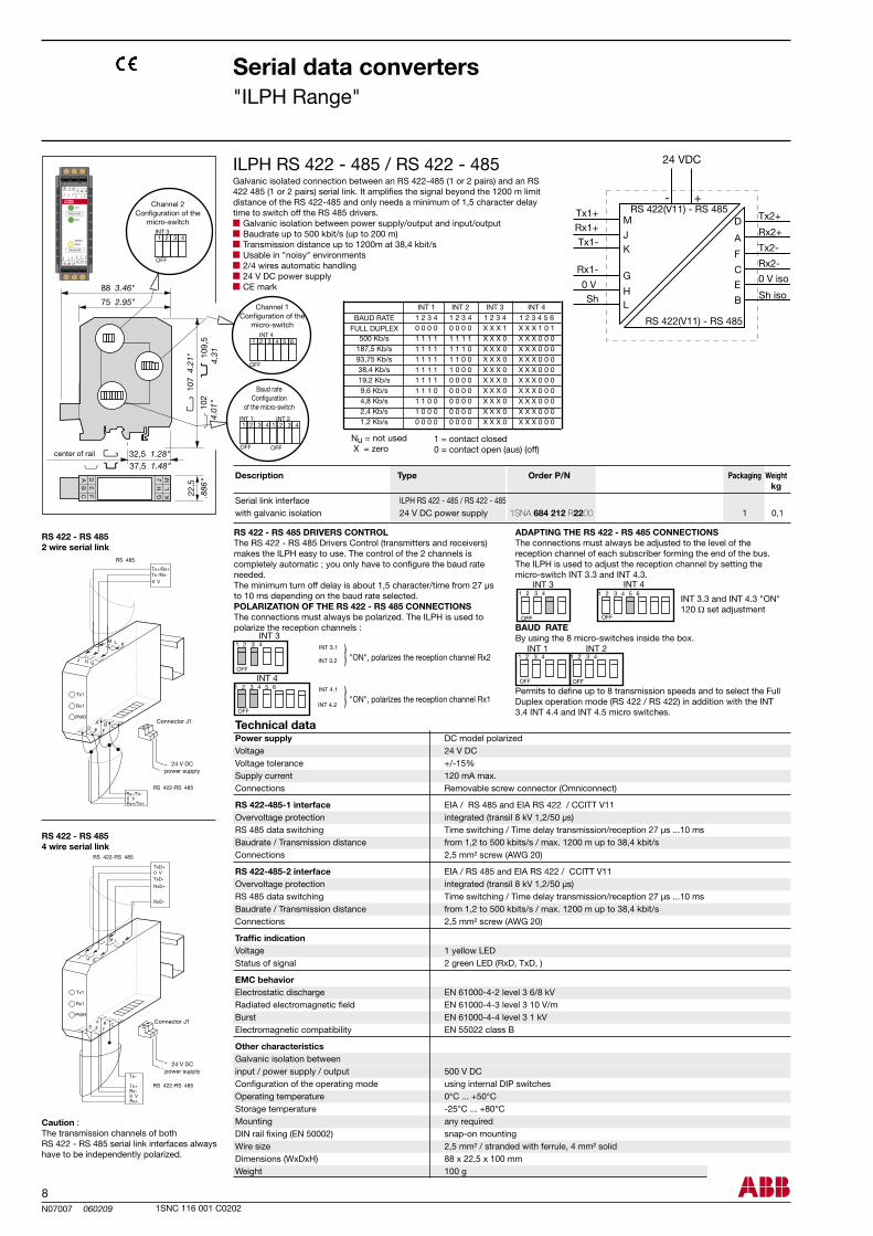
500 Kb/s187,5 Kb/s93,75 Kb/s38,4 Kb/s19,2 Kb/s9,6 Kb/s4,8 Kb/s2,4 Kb/s1,2 Kb/s
INT 1 1 2 3 4 0 0 0 0 1 1 1 1 1 1 1 1 1 1 1 1 1 1 1 1 1 1 1 1 1 1 1 0 1 1 0 0 1 0 0 0 0 0 0 0
INT 2 1 2 3 4 0 0 0 0 1 1 1 1 1 1 1 0 1 1 0 0 1 0 0 0 0 0 0 0 0 0 0 0 0 0 0 0 0 0 0 0 0 0 0 0
INT 3 1 2 3 4 X X X 1 X X X 0 X X X 0 X X X 0
X X X 0X X X 0X X X 0X X X 0X X X 0X X X 0
INT 4 1 2 3 4 5 6
X X X 1 0 1X X X 0 0 0X X X 0 0 0X X X 0 0 0X X X 0 0 0X X X 0 0 0X X X 0 0 0X X X 0 0 0X X X 0 0 0X X X 0 0 0
ILPH RS 422 - 485 / RS 422 - 485
1SNC 116 001 C0202
Serial data converters"ILPH Range"
Galvanic isolated connection between an RS 422-485 (1 or 2 pairs) and an RS 422 485 (1 or 2 pairs) serial link. It amplifies the signal beyond the 1200 m limit distance of the RS 422-485 and only needs a minimum of 1,5 character delay time to switch off the RS 485 drivers.
Galvanic isolation between power supply/output and input/output Baudrate up to 500 kbit/s (up to 200 m) Transmission distance up to 1200m at 38,4 kbit/s Usable in "noisy" environments 2/4 wires automatic handling 24 V DC power supply CE mark
Power supply DC model polarized Voltage 24 V DC Voltage tolerance +/-15% Supply current 120 mA max. Connections Removable screw connector (Omniconnect)
RS 422-485-1 interface EIA / RS 485 and EIA RS 422 / CCITT V11 Overvoltage protection integrated (transil 8 kV 1,2/50 µs) RS 485 data switching Time switching / Time delay transmission/reception 27 µs ...10 ms Baudrate / Transmission distance from 1,2 to 500 kbits/s / max. 1200 m up to 38,4 kbit/s Connections 2,5 mm² screw (AWG 20)
RS 422-485-2 interface EIA / RS 485 and EIA RS 422 / CCITT V11 Overvoltage protection integrated (transil 8 kV 1,2/50 µs) RS 485 data switching Time switching / Time delay transmission/reception 27 µs ...10 ms Baudrate / Transmission distance from 1,2 to 500 kbits/s / max. 1200 m up to 38,4 kbit/s Connections 2,5 mm² screw (AWG 20)
Traffic indication Voltage 1 yellow LED Status of signal 2 green LED (RxD, TxD, )
EMC behavior Electrostatic discharge EN 61000-4-2 level 3 6/8 kV Radiated electromagnetic field EN 61000-4-3 level 3 10 V/m Burst EN 61000-4-4 level 3 1 kV Electromagnetic compatibility EN 55022 class B
Other characteristics Galvanic isolation between input / power supply / output 500 V DC Configuration of the operating mode using internal DIP switches Operating temperature 0°C ... +50°C Storage temperature -25°C ... +80°C Mounting any required DIN rail fixing (EN 50002) snap-on mounting Wire size 2,5 mm² / stranded with ferrule, 4 mm² solid Dimensions (WxDxH) 88 x 22,5 x 100 mm Weight 100 g
Caution : The transmission channels of both RS 422 - RS 485 serial link interfaces always have to be independently polarized.
RS 422 - RS 4854 wire serial link
RS 422 - RS 4852 wire serial link
24 V DCpower supply
Connector J1
24 V DCpower supply
Connector J1
"ON", polarizes the reception channel Rx2
"ON", polarizes the reception channel Rx1
RS 422 - RS 485 DRIVERS CONTROLThe RS 422 - RS 485 Drivers Control (transmitters and receivers) makes the ILPH easy to use. The control of the 2 channels iscompletely automatic ; you only have to configure the baud rate needed. The minimum turn off delay is about 1,5 character/time from 27 µs to 10 ms depending on the baud rate selected.POLARIZATION OF THE RS 422 - RS 485 CONNECTIONSThe connections must always be polarized. The ILPH is used to polarize the reception channels :
ADAPTING THE RS 422 - RS 485 CONNECTIONSThe connections must always be adjusted to the level of the reception channel of each subscriber forming the end of the bus. The ILPH is used to adjust the reception channel by setting the micro-switch INT 3.3 and INT 4.3.
BAUD RATEBy using the 8 micro-switches inside the box.
Permits to define up to 8 transmission speeds and to select the FullDuplex operation mode (RS 422 / RS 422) in addition with the INT 3.4 INT 4.4 and INT 4.5 micro switches.
INT 3.3 and INT 4.3 "ON"120 Ω set adjustment
Nu = not used X = zero
center of rail
Channel 1Configuration of the
micro-switch
Channel 2Configuration of the
micro-switch
Baud rateConfiguration
of the micro-switch
1 = contact closed0 = contact open (aus) (off)
BAUD RATEFULL DUPLEX
Serial link interface with galvanic isolation 24 V DC power supply
Description Type Order P/N Packaging Weight kg
Technical data
1SNA 684 212 R2200
9N07008 060209
ILPH RS 232 / FO-S 1 0,15 1 0,15
ILPH RS 232 / FO-P 1 0,15 1 0,15
RS 232 / FO
RxDOV
TxD
OV
←→
~+
~-
(L)
(K)(M)
(J H G)
(E)
(F)(D)
(B)
(C)
(A)
ILPH RS 232 / FO
1SNC 116 001 C0202
Serial data converters"ILPH Range"
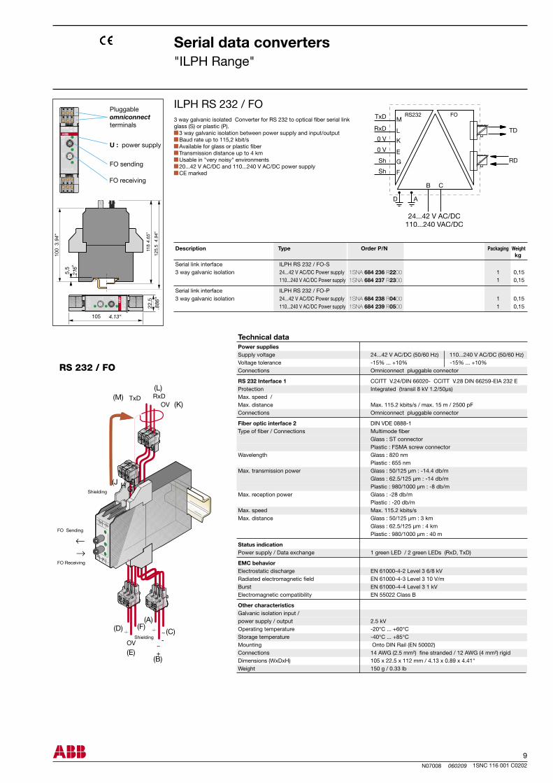
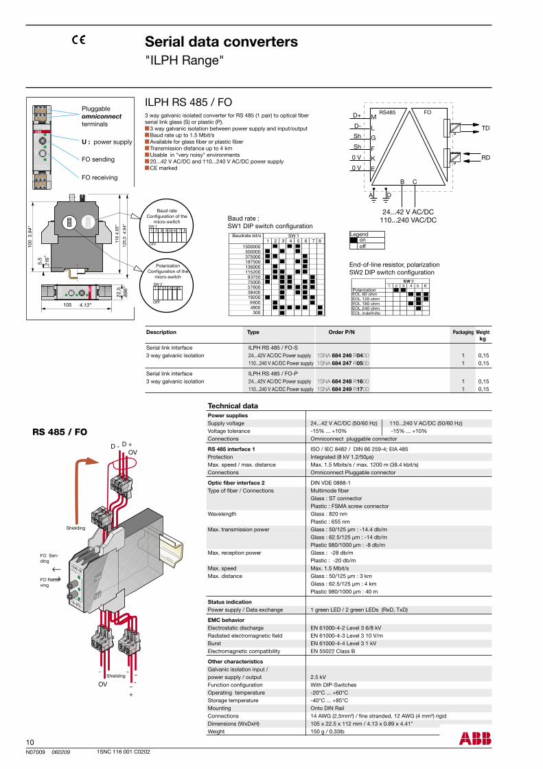
3 way galvanic isolated Converter for RS 232 to optical fiber serial link glass (S) or plastic (P).
3 way galvanic isolation between power supply and input/output Baud rate up to 115,2 kbit/s Available for glass or plastic fiber Transmission distance up to 4 km Usable in "very noisy" environments 20...42 V AC/DC and 110...240 V AC/DC power supply CE marked
Power supplies Supply voltage 24...42 V AC/DC (50/60 Hz) 110...240 V AC/DC (50/60 Hz) Voltage tolerance -15% ... +10% -15% ... +10% Connections Omniconnect pluggable connector
RS 232 Interface 1 CCITT V.24/DIN 66020- CCITT V.28 DIN 66259-EIA 232 E Protection Integrated (transil 8 kV 1.2/50µs) Max. speed / Max. distance Max. 115.2 kbits/s / max. 15 m / 2500 pF Connections Omniconnect pluggable connector
Fiber optic interface 2 DIN VDE 0888-1 Type of fiber / Connections Multimode fiber Glass : ST connector Plastic : FSMA screw connector Wavelength Glass : 820 nm Plastic : 655 nm Max. transmission power Glass : 50/125 µm : -14.4 db/m Glass : 62.5/125 µm : -14 db/m Plastic : 980/1000 µm : -8 db/m Max. reception power Glass : -28 db/m Plastic : -20 db/m Max. speed Max. 115.2 kbits/s Max. distance Glass : 50/125 µm : 3 km Glass : 62.5/125 µm : 4 km Plastic : 980/1000 µm : 40 m
Status indication Power supply / Data exchange 1 green LED / 2 green LEDs (RxD, TxD)
EMC behavior Electrostatic discharge EN 61000-4-2 Level 3 6/8 kV Radiated electromagnetic field EN 61000-4-3 Level 3 10 V/m Burst EN 61000-4-4 Level 3 1 kV Electromagnetic compatibility EN 55022 Class B
Other characteristics Galvanic isolation input / power supply / output 2.5 kV Operating temperature -20°C ... +60°C Storage temperature -40°C ... +85°C Mounting Onto DIN Rail (EN 50002) Connections 14 AWG (2.5 mm²) fine stranded / 12 AWG (4 mm²) rigid Dimensions (WxDxH) 105 x 22.5 x 112 mm / 4.13 x 0.89 x 4.41" Weight 150 g / 0.33 lb
Technical data
Shielding
FO Sending
FO Receiving
Shielding
Serial link interface 3 way galvanic isolation 24...42 V AC/DC Power supply 110...240 V AC/DC Power supply
Serial link interface 3 way galvanic isolation 24...42 V AC/DC Power supply 110...240 V AC/DC Power supply
U : power supply
FO sending
FO receiving
Pluggableomniconnect terminals
Description Type Order P/N Packaging Weight kg
1SNA 684 236 R2200 1SNA 684 237 R2300
1SNA 684 238 R0400 1SNA 684 239 R0500
10N07009 060209
ILPH RS 485 / FO-S 1 0,15 1 0,15
ILPH RS 485 / FO-P 1 0,15 1 0,15
OFF
1 2 3 4 5 6 7 8SW 1
OFF
SW 2 1 2 3 4 5 6
ILPH RS 485 / FO
RS 485 / FO
←
OVD - D +
OV
←
~-
~+
onoff
1SNC 116 001 C0202
Serial data converters"ILPH Range"
3 way galvanic isolated converter for RS 485 (1 pair) to optical fiber serial link glass (S) or plastic (P).
3 way galvanic isolation between power supply and input/output Baud rate up to 1.5 Mbit/s Available for glass fiber or plastic fiber Transmission distance up to 4 km Usable in "very noisy" environments 20...42 V AC/DC and 110...240 V AC/DC power supply CE marked
Baud rate :SW1 DIP switch configuration
Legend
End-of-line resistor, polarizationSW2 DIP switch configuration
Baudrate bit/s
U : power supply
Pluggable omniconnect terminals
FO sending
FO receiving
PolarizationConfiguration of the
micro-switch
Baud rateConfiguration of the
micro-switch
Power supplies Supply voltage 24...42 V AC/DC (50/60 Hz) 110...240 V AC/DC (50/60 Hz) Voltage tolerance -15% ... +10% -15% ... +10% Connections Omniconnect pluggable connector
RS 485 interface 1 ISO / IEC 8482 / DIN 66 259-4; EIA 485 Protection Integrated (8 kV 1.2/50µs) Max. speed / max. distance Max. 1.5 Mbits/s / max. 1200 m (38.4 kbit/s) Connections Omniconnect Pluggable connector
Optic fiber interface 2 DIN VDE 0888-1 Type of fiber / Connections Multimode fiber Glass : ST connector Plastic : FSMA screw connector Wavelength Glass : 820 nm Plastic : 655 nm Max. transmission power Glass : 50/125 µm : -14.4 db/m Glass : 62.5/125 µm : -14 db/m Plastic 980/1000 µm : -8 db/m Max. reception power Glass : -28 db/m Plastic : -20 db/m Max. speed Max. 1.5 Mbit/s Max. distance Glass : 50/125 µm : 3 km Glass : 62.5/125 µm : 4 km Plastic 980/1000 µm : 40 m
Status indication Power supply / Data exchange 1 green LED / 2 green LEDs (RxD, TxD)
EMC behavior Electrostatic discharge EN 61000-4-2 Level 3 6/8 kV Radiated electromagnetic field EN 61000-4-3 Level 3 10 V/m Burst EN 61000-4-4 Level 3 1 kV Electromagnetic compatibility EN 55022 Class B
Other characteristics Galvanic isolation input / power supply / output 2.5 kV Function configuration With DIP-Switches Operating temperature -20°C ... +60°C Storage temperature -40°C ... +85°C Mounting Onto DIN Rail Connections 14 AWG (2,5mm²) / fine stranded, 12 AWG (4 mm²) rigid Dimensions (WxDxH) 105 x 22.5 x 112 mm / 4.13 x 0.89 x 4.41" Weight 150 g / 0.33lb
Technical data
Description Type Order P/N Packaging Weight kg
Serial link interface 3 way galvanic isolation 24...42V AC/DC Power supply 110...240 V AC/DC Power supply
Serial link interface 3 way galvanic isolation 24...42V AC/DC Power supply 110...240 V AC/DC Power supply
Shielding
FO Sen-ding
FO Recei-ving
Shielding
1SNA 684 246 R0400 1SNA 684 247 R0500
1SNA 684 248 R1600 1SNA 684 249 R1700
11N07010 060209
ILPH BdC / RS 422 - 485 1 0,1
INT4
R
E
INT2
INT3
R
E
INT2 R ON INT3 E ON / OFF
R
E
INT2 R ON
INT3 E ON
Rt
Rt INT1
INT1
S1 S2 S3 S4ON OFF
INT4
INT1 INT2 INT3
Rt E R
S1 S2 S3 S4
INT4
onoff
1SNC 116 001 C0202
LINE AMPLIFIER CONFIGURATIONConfiguration of amplifiers of the RS 422 - RS 485 (Receiver, Trans-mitter) line provides greater flexibility of use.The various configurations can be selected using the 2 jumpers (R INT2, E INT1) located inside the box.
RS 485 LINK ON ONE PAIR
The Receiver and the Transmitter are activated alternately (never at the same time) depending on the status of the Current Loop Reception signal.
RS 485 LINK ON TWO PAIRS
Receiver permanently active. Transmitter controlled by the Current Loop Reception signal.
RS 422 LINK ON TWO PAIRS
The Receiver and the Transmitter are both permanently active.
Serial data converters"ILPH Range"
Configuration of the jumper
Configurationof the micro-switches
Polarization
center of rail
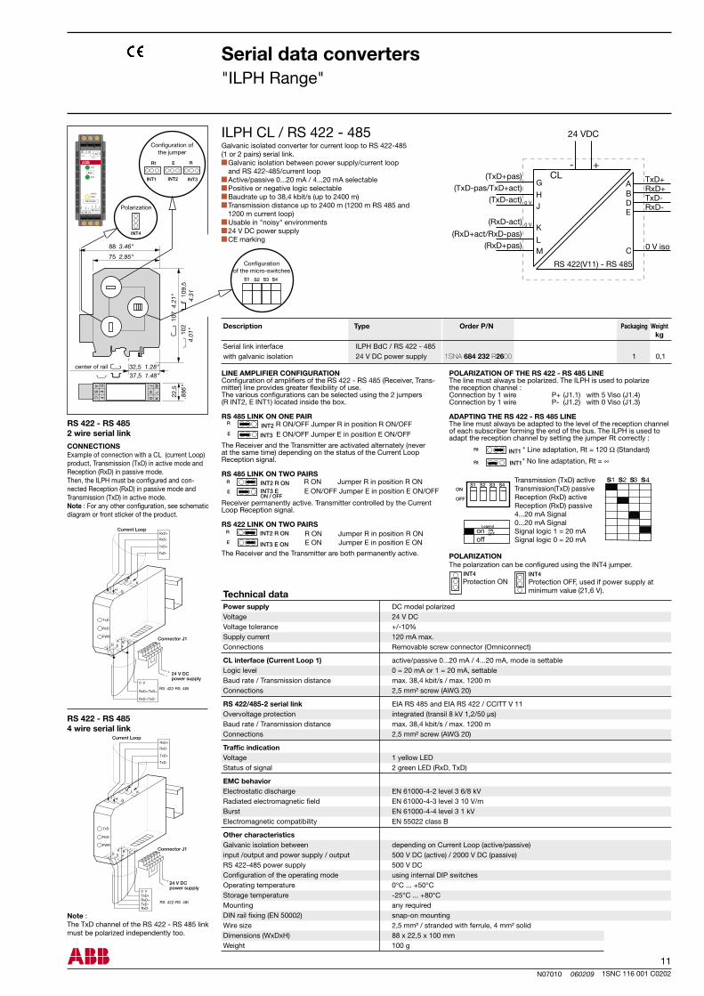
Galvanic isolated converter for current loop to RS 422-485 (1 or 2 pairs) serial link.
Galvanic isolation between power supply/current loop and RS 422-485/current loop
Active/passive 0...20 mA / 4...20 mA selectable Positive or negative logic selectable Baudrate up to 38,4 kbit/s (up to 2400 m) Transmission distance up to 2400 m (1200 m RS 485 and
1200 m current loop) Usable in "noisy" environments 24 V DC power supply CE marking
Serial link interface with galvanic isolation 24 V DC power supply
Technical data
RS 422 - RS 4852 wire serial link
CONNECTIONSExample of connection with a CL (current Loop) product, Transmission (TxD) in active mode and Reception (RxD) in passive mode.Then, the ILPH must be configured and con-nected Reception (RxD) in passive mode and Transmission (TxD) in active mode.Note : For any other configuration, see schematic diagram or front sticker of the product.
Note : The TxD channel of the RS 422 - RS 485 link must be polarized independently too.
RS 422 - RS 4854 wire serial link
Current Loop
Connector J1
24 V DCpower supply
Current Loop
Connector J1
24 V DCpower supply
Protection ON
Protection OFF, used if power supply at minimum value (21,6 V).
Power supply DC model polarized Voltage 24 V DC Voltage tolerance +/-10% Supply current 120 mA max. Connections Removable screw connector (Omniconnect)
CL interface (Current Loop 1) active/passive 0...20 mA / 4...20 mA, mode is settable Logic level 0 = 20 mA or 1 = 20 mA, settable Baud rate / Transmission distance max. 38,4 kbit/s / max. 1200 m Connections 2,5 mm² screw (AWG 20)
RS 422/485-2 serial link EIA RS 485 and EIA RS 422 / CCITT V 11 Overvoltage protection integrated (transil 8 kV 1,2/50 µs) Baud rate / Transmission distance max. 38,4 kbit/s / max. 1200 m Connections 2,5 mm² screw (AWG 20)
Traffic indication Voltage 1 yellow LED Status of signal 2 green LED (RxD, TxD)
EMC behavior Electrostatic discharge EN 61000-4-2 level 3 6/8 kV Radiated electromagnetic field EN 61000-4-3 level 3 10 V/m Burst EN 61000-4-4 level 3 1 kV Electromagnetic compatibility EN 55022 class B
Other characteristics Galvanic isolation between depending on Current Loop (active/passive) input /output and power supply / output 500 V DC (active) / 2000 V DC (passive) RS 422-485 power supply 500 V DC Configuration of the operating mode using internal DIP switches Operating temperature 0°C ... +50°C Storage temperature -25°C ... +80°C Mounting any required DIN rail fixing (EN 50002) snap-on mounting Wire size 2,5 mm² / stranded with ferrule, 4 mm² solid Dimensions (WxDxH) 88 x 22,5 x 100 mm Weight 100 g
E ON/OFF Jumper E in position E ON/OFFR ON/OFF Jumper R in position R ON/OFF
R ON Jumper R in position R ONE ON/OFF Jumper E in position E ON/OFF
R ON Jumper R in position R ONE ON Jumper E in position E ON
POLARIZATION OF THE RS 422 - RS 485 LINEThe line must always be polarized. The ILPH is used to polarizethe reception channel :Connection by 1 wire P+ (J1.1) with 5 Viso (J1.4)Connection by 1 wire P- (J1.2) with 0 Viso (J1.3)
ADAPTING THE RS 422 - RS 485 LINEThe line must always be adapted to the level of the reception channel of each subscriber forming the end of the bus. The ILPH is used to adapt the reception channel by setting the jumper Rt correctly :
POLARIZATIONThe polarization can be configured using the INT4 jumper.
* Line adaptation, Rt = 120 Ω (Standard)
* No line adaptation, Rt = ∞
Transmission (TxD) activeTransmission(TxD) passiveReception (RxD) activeReception (RxD) passive4...20 mA Signal0...20 mA SignalSignal logic 1 = 20 mA Signal logic 0 = 20 mA
LegendONOFF
Description Type Order P/N Packaging Weight kg
ILPH CL / RS 422 - 485
CL
1SNA 684 232 R2600
12N07011 060209
ILPH RS 232 / BdC 1 0,1
S1 S2 S3 S4
S1 S2 S3 S4ON
OFF
S1 S2 S3 S4ON
OFF
S1 S2 S3 S4ON
OFF
1SNC 116 001 C0202
Serial data converters"ILPH Range"
Technical data
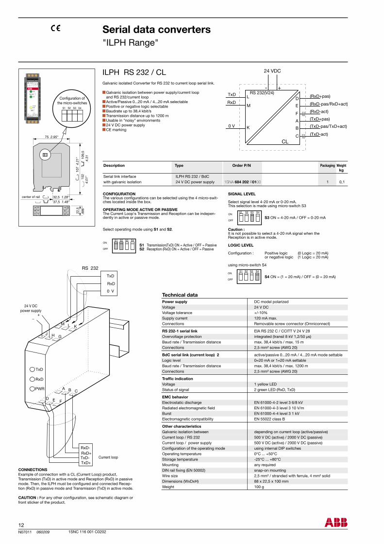
Galvanic isolated Converter for RS 232 to current loop serial link.
Galvanic isolation between power supply/current loop and RS 232/current loop
Active/Passive 0...20 mA / 4...20 mA selectable Positive or negative logic selectable Baudrate up to 38,4 kbit/s Transmission distance up to 1200 m Usable in "noisy" environments 24 V DC power supply CE marking
Configuration of the micro-switches
center of rail
Serial link interface with galvanic isolation 24 V DC power supply
Power supply DC model polarized Voltage 24 V DC Voltage tolerance +/-10% Supply current 120 mA max. Connections Removable screw connector (Omniconnect)
RS 232-1 serial link EIA RS 232 C / CCITT V 24 V 28 Overvoltage protection integrated (transil 8 kV 1,2/50 µs) Baud rate / Transmission distance max. 38,4 kbit/s / max. 15 m Connections 2,5 mm² screw (AWG 20)
BdC serial link (current loop) 2 active/passive 0...20 mA / 4...20 mA mode settable Logic level 0=20 mA or 1=20 mA settable Baud rate / Transmission distance max. 38,4 kbit/s / max. 1200 m Connections 2,5 mm² screw (AWG 20)
Traffic indication Voltage 1 yellow LED Status of signal 2 green LED (RxD, TxD)
EMC behavior Electrostatic discharge EN 61000-4-2 level 3 6/8 kV Radiated electromagnetic field EN 61000-4-3 level 3 10 V/m Burst EN 61000-4-4 level 3 1 kV Electromagnetic compatibility EN 55022 class B
Other characteristics Galvanic isolation between depending on current loop (active/passive) Current loop / RS 232 500 V DC (active) / 2000 V DC (passive) Current loop / power supply 500 V DC (active) / 2000 V DC (passive) Configuration of the operating mode using internal DIP switches Operating temperature 0°C ... +50°C Storage temperature -25°C ... +80°C Mounting any required DIN rail fixing (EN 50002) snap-on mounting Wire size 2,5 mm² / stranded with ferrule, 4 mm² solid Dimensions (WxDxH) 88 x 22,5 x 100 mm Weight 100 g
Current loop
24 V DCpower supply
CONNECTIONSExample of connection with a CL (Current Loop) product,Transmission (TxD) in active mode and Reception (RxD) in passive mode. Then, the ILPH must be configured and connected Recep-tion (RxD) in passive mode and Transmission (TxD) in active mode. CAUTION : For any other configuration, see schematic diagram or front sticker of the product.
CONFIGURATIONThe various configurations can be selected using the 4 micro-swit-ches located inside the box.
OPERATING MODE ACTIVE OR PASSIVEThe Current Loop's Transmission and Reception can be indepen-dently in active or passive mode.
Select operating mode using S1 and S2.
S1 Transmission(TxD) ON = Active / OFF = Passive S2 Reception (RxD) ON = Active / OFF = Passive
SIGNAL LEVEL
Select signal level 4-20 mA or 0-20 mA.This selection is made using micro-switch S3
S3 ON = 4-20 mA / OFF = 0-20 mA
Caution : It is not possible to select a 4-20 mA signal when theReception is in active mode.
LOGIC LEVEL
Configuration : Positive logic (0 Logic = 20 mA) or negative logic (1 Logic = 20 mA)
using micro-switch S4
S4 ON = (1 = 20 mA) / OFF = (0 = 20 mA)
Description Type Order P/N Packaging Weight kg
ILPH RS 232 / CL
CL
1SNA 684 202 R0100


As part of its on-going product improvement, ABB reserves the right to modify the characteristics or the products described in this document.The information given is not-contractual. For further details please contact the ABB company marketing these products in your country.
ABB EntrelecExport Department10, rue Ampère Z.I. - B.P. 114 F-69685 Chassieu cedex / France Tel. : +33 (0) 4 7222 1722 Fax : +33 (0) 4 7222 1935
1SN
C 1
60 0
01 C
0202
Prin
ted
in F
ranc
e (V
07.
2006
- B
raill
y)