Embed Size (px)
Citation preview

September 19/20, 2007
SIS 100Magnet cooling
andcryogenic distribution

September 19/20, 2007
Feed box
Feed
bo
x
Refrigerator
Distribution box
Reference
magnets
Feed
box
Supply line
Return line
shield cooling
transfer lines
4.4 K
4.3 K
50-80 K
. . .
. . .
. . . . .
. .
. . . . .
. .
. . . . .. .
. . . . .. .
. . . . .
. . .
Each sextant consists:18 Dipoles28 Quadrupoles24 Correctors? Scraper4 warm sections
Length: 180 m
SIS100
No collimators at cryogenic temperature

September 19/20, 2007
User 1 User 2 User i
supply
return
p
SIS100 cooling scheme
conditionsinletgeometryQmfp ,,
Maximal p = ? => dipole
All other users have to be adopted to this pressure drop p by:• introducing an orifice at the inlet (small rage due to manufacturing accuracy and/ or • Combination of different users

September 19/20, 2007
SIS100 cooling scheme
System requires nearly no pressure drop along the supply lines to achieve the same pressure head along the sector for every component.
psupply < 50 mbarpsuction< 20 mbar
dsupply = 0,038 m (0,045m) dsuction= 0,070 m (0,060 m)

September 19/20, 2007
Maximal flow given by the geometry <=> flow impedance
Minimal flow given by flow regime: slug or plug flow have to be avoided to reach equal temperature distribution within the coilpressure control
Vapour fraction at yoke outlet should be kept between .9 and 1., to achieve an energy efficient operation
SIS100 cooling dipole

September 19/20, 2007
Internal heat exchangerRecooler between supply line and magnet cooling
length string [m] 200length magnet [m] 2,4
supply line supply tube magnet
material Stainlessdiameter [m] 0,038 0,045thickness [m] 0,0015cross section [m 2̂] 0,0011 0,0016 0,000162pressure [Pa] 150000 1,10E+05Temperature [K] 4,5 4,5 4,31void fraction [-] 0 0,3
density [kg/m 3̂] 120,7 45,4Prandtl [-] 1,009
viscostity i [Pa s] 3,08E-06heat conductivity [W/mK] 0,0190 0,2644
mass flow rate [kg/s] 0,05 0,075 0,002Re [-] 5,44E+05 6,89E+05 [-] 0,0128 0,0123Nu [-] 881,4 1071,6
[W/m 2̂K] 441,1 452,8 176,2 1000
k [W/m 2̂K] 111,84 112,58A [m 2̂/m] 0,018T [K] 0,2
Q [W/m] 0,40 0,41
Approx. 50mdipole/200msextant= 0,25 => Qmax,supply=0.1 W/m
Supply line

September 19/20, 2007
SIS100 inlet conditions
4,40
4,42
4,44
4,46
4,48
4,50
4,52
0 20 40 60 80 100 120 140 160
length of a sector [m]
Te
mp
erat
ure
[K
]
no pressure loss
20kPa pressure lossUser 1 User 2 User i
supply
return
p
Q.
Subcooledfrom feed box
towards feed box
= 0.1W/m

September 19/20, 2007
Two traditional Nuclotron magnets:
Tests
0
0,1
0,2
0,3
0,4
0,5
0,6
0,7
0,8
0,9
1
0 5 10 15 20 25 30 35 40
Heat load [W]
pre
ssu
re d
rop
[b
ar]
Cycle 2c'
Cycle 1,2a
Cycle 3
Cycle 4,5'
sta
ble
ope
ratio
n
Cycle 3b

September 19/20, 2007
SIS100 cooling dipole
Curved double layer dipole
WkbBaP coildyn 3.911max1,
WkbBaP yokedyn 6.3022max2,
WP coilstat 1,
Cycle 2cB= 0 -> 1.9 TB=4T/scycle=1.8 s
.
WP yokestat 2,

September 19/20, 2007
SIS100 cooling
Coili
Yoke
supply
return
2
2v
d
lp
i
Pressure drop calculations
3.0Re3964.000540.0(Re) f Hermann, 2.104 < Re < 2.106
1vl
0,1,0,, xpvxpvxxpvxpv outoutoutoutoutoutout

September 19/20, 2007
SIS100 cooling
Pressure drop measurement
N 2
M a gne tflowm e te r
p0
2
4
6
8
10
12
14
0 0,5 1 1,5 2 2,5 3 3,5 4 4,5
mass flow rate [g/s]
pre
ssu
re d
rop
[b
ar]
Reihe1
Reihe2
Reihe3
calculated

September 19/20, 2007
SIS100 cooling
Tin=4.5K; Pin=1.56 bar; Psuction=1.1 bar; m=2.45g/s; coil= 63s, Yoke= 12 s
4,1
4,2
4,3
4,4
4,5
4,6
4,7
4,8
4,9
3 4 5 6 7 8 9
Entropy [J/gK]
Te
mp
era
ture
[K
]
x=0,25 x=0,5 x=0,75x=0 x=1
p=1 bar
p=1,3 bar
p=1,5 bar

September 19/20, 2007
SIS100 cooling
Tin=4.5K; Pin=1.56 bar; Psuction=1.1 bar; m=2.45g/s; coil= 66s, Yoke= 12 s
4,2
4,3
4,4
4,5
4,6
4,7
4,8
3,4 4,4 5,4 6,4 7,4 8,4 9,4
Entropy [J/gK]
Te
mp
era
ture
[K
]
d_i=0.0047m
d_i=0.0047m
x=0,5x=0
x=1
p=1,25 bar
p=1,5 bar
2,182,4501,900
1,56
1,51
p_in
p=1,0 bar
Tin=4.5K; Pin=1.51 bar; Psuction=1.12 bar; m=2.18g/s; coil= 68s, Yoke= 13 s

September 19/20, 2007
SIS100 cooling
Tin=4.5K; Pin=1.56 bar; Psuction=1.1 bar; m=2.45g/s; coil= 66s, Yoke= 12 s
Tin=4.4K; Pin=1.56 bar; Psuction=1.1 bar; m=2.56g/s; coil= 66s, Yoke= 12 s
4,2
4,3
4,4
4,5
4,6
4,7
4,8
3,4 4,4 5,4 6,4 7,4 8,4 9,4
Entropy [J/gK]
Te
mp
era
ture
[K
]
d_i=0.0047m
d_i=0.0047m
x=0,5x=0
x=1
p=1,25 bar
p=1,5 bar
2,182,4502,5550
1,56
1,56
p_in
p=1,0 bar

September 19/20, 2007
Tin = 4.51K
SIS100 cooling
4,4
4,5
4,6
4,7
4,8
4,9
5
5,1
1,0 1,5 2,0 2,5 3,0 3,5 4,0
mass flow [g/s]
max
. co
il te
mp
erat
ure
[K
]
1,41,61,82x=1x=0.9p_suction=1.1
inletpressure [bar]
field of operation
September 19/20, 2007
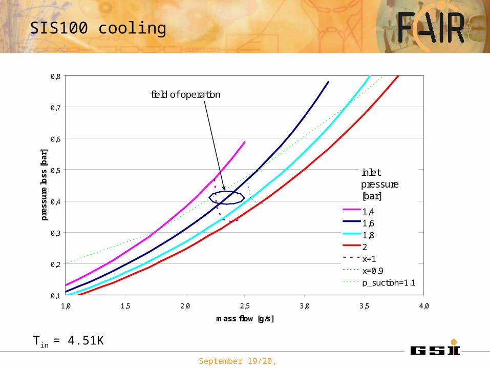
SIS100 cooling
Tin = 4.51K
0,1
0,2
0,3
0,4
0,5
0,6
0,7
0,8
1,0 1,5 2,0 2,5 3,0 3,5 4,0
mass flow [g/s]
pre
ssu
re lo
ss
[ba
r]
1,41,61,82x=1x=0.9p_suction=1.1
inletpressure [bar]
field of operation

September 19/20, 2007
SIS100 cooling
Tin = 4.51K
4
4,2
4,4
4,6
4,8
5
5,2
5,4
5,6
5,8
6
1,0 1,5 2,0 2,5 3,0 3,5 4,0
mass flow [g/s]
ou
tle
t te
mp
era
ture
[K]
1,41,61,82x=1x=0.9p_suction=1.1
inletpressure [bar]
superheating
liquid left in the
field of operation

September 19/20, 2007
0,1
0,2
0,3
0,4
0,5
0,6
0,7
0,8
1,0 1,5 2,0 2,5 3,0 3,5 4,0
mass flow [g/s]
pre
ssu
re lo
ss [
bar
]
1,4
1,6
1,8
2x=1
x=0.9
p_suction=1.1
inletpressure [bar]
field of operation
Tin = 4.5K
SIS100 cooling

September 19/20, 2007
SIS100 cooling

September 19/20, 2007
Curved double layer option• There is a common range of pressures of operation, where both magnets, the first and the last will work, but
• The heat load onto the supply line should not exceed .08 W/m in the magnet cryostats. This should be possible be special shielding from the return line.
•To achieve a similar operational field, following groups for the correction elements are proposed by H. Khodzhibagiyan:
• Module M1: a quadrupole, pickup and steerer• Module M2: a quadrupole, pickup and multipole• Module M3: a quadrupole, multipole and collimator• Module M4: a quadrupole, steerer and collimator
• The beam pipe cooling should be handled as a separate consumer and be put into the modules M1..M4
SIS100 cooling

September 19/20, 2007
SIS100 cooling
0
0,2
0,4
0,6
0,8
1
1,2
0 0,2 0,4 0,6 0,8 1
duty cycle/max. cycle [-]
heat
load
/ max
. hea
tload
[-]
0
0,2
0,4
0,6
0,8
1
1,2
requ
ired
pres
sure
hea
d/ d
esig
n pr
essu
re
head
[-]
staticpower 2linear
Dipole: static load 7W, load in cycle 2c: 35.7 WQuadrupole: static load 4W, load in cycle 2c: 18.7 WCorrectors: ?Beam pipe cooling:?Scraper: ?

September 19/20, 2007
Dipole1
Quadru-pole
600 m
supply line
return line
p supply, beam pipe cooling
p suction
p1
p14
1
preturn line
beam pipe cooling
p supply, quadrupole
p supply, dipole
180 m

September 19/20, 2007
Feed box
Feed
bo
x
Refrigerator
Distribution box Feed
box
Supply line
Return line
shield cooling
transfer lines
4.4 K
4.3 K
50-80 K
. . .
. . .
. . . . .
. . . . . . .
. .
. . . . .. .
. . . . .. .
. . . . .
. . .
• Feed box on tunnel level in niche=> short reaction time for the control valves• Transfer lines through the tunnel• as few valves as possible in the non accessible area

September 19/20, 2007
• Distribution box on tunnel level in niche=> Smaller space requirements in the transfer section• Transfer lines through the tunnel• valves in the non accessible area
Feed box
Feed
bo
x
Refrigerator
Feed
box
Supply line
Return line
shield cooling
transfer lines
4.4 K
4.3 K
50-80 K
. . .
. . .
. . . . .
. .
. . . . .
. .
. . . . .. .
. . . . .. .
. . . . .
. . .D
istribution
box

September 19/20, 2007
SIS100 cooling
-> T
o R
efr
ige
rato
r
Supply line
Return line
motive gas
shield cooling
transfer lines
bus bar
4.4 K
4.3 K
4.4 K
50-80 K
Feed box
PS PS
compressor
...
...

September 19/20, 2007

September 19/20, 2007
0,5
0,52
0,54
0,56
0,58
0,6
0,62
0,64
0,66
4 5 6 7 8 9 10 11
heat load on coil [W]
pre
ssu
re d
rop
[b
ar]
0,24 0,3 0,31
Classic Nuclotron
Prototype specification
liron
coil iron
Qcoil
. Qiron
.
lcoil
pin, Tin, xin, m.
pout, Tout, xout
Pressure drop versus heat load on the coil for a constant overall heat load of 30 W.

September 19/20, 2007
4,2
4,3
4,4
4,5
4,6
4,7
4,8
3,4 4,4 5,4 6,4 7,4 8,4 9,4
Entropy [J/gK]
Te
mp
era
ture
[K
]
first
middle
end
equal
x=0,5x=0
x=0,9
p=1,25
p=1,5 bar
1,70501,70501,705
1,672
1,669
1,6718
p_in
1,6713
p=1,0 bar
liron
Qcoil
.
lcoil
Qironlastfirst middle
T-s-Diagram for three different load distribution onto the coil. The pressure drop variation caused by this load variation is below 2 mbar (or .5%).