Embed Size (px)
Citation preview
Separator ManualHigh Speed Separator
S 927
Specification No. 881201-08-03/3Book No. 9006916-02 rev. 3
Published By:
Alfa Laval Tumba AB
SE-147 80 Tumba, Sweden
Telephone: +46 8 530 650 00
Telefax: +46 8 530 310 40
© Alfa Laval Tumba AB 04-2014
The original instructions are in English
This publication or any part there of may not bereproduced or transmitted by any process ormeans without prior written permission of AlfaLaval Tumba AB.
Contents
1 Read this first 9
2 Safety instructions 11
2.1 Warning signs in text 15
2.2 Environmental issues 16
2.3 Requirements of personnel 17
2.4 Remote start 17
3 Basic principles of separation 19
3.1 Introduction 19
3.2 Separation by gravity 19
3.3 Centrifugal separation 20
3.4 Separating temperatures 20
4 Design and function 21
4.1 Overview 22
4.2 Drive section 23
4.3 Process section 24
4.4 Sensors and indicators 26
4.5 Separating function 274.5.1 The liquid balance in the bowl 274.5.2 Liquid flow 284.5.3 Discharge of sludge and water (ALCAP™ concept) 294.5.4 Discharge of water through water outlet 30
5 Operating instructions 31
5.1 Before first start 315.1.1 Start after service 32
5.2 Normal operation 335.2.1 Before normal start 335.2.2 Start 345.2.3 Operating 365.2.4 Stop 38
5.3 Emergency stop 39
3
6 Service, dismantling, assembly 41
6.1 Periodic maintenance 416.1.1 Maintenance intervals 416.1.2 Maintenance procedure 436.1.3 Tightening of screws 446.1.4 Service kits 456.1.5 Cleaning 45
6.2 Maintenance logs 46
6.3 Dismantling 496.3.1 Introduction 496.3.2 Tools 496.3.3 Frame hood 516.3.4 Bowl 556.3.5 Driving device 726.3.6 Centrifugal clutch 91
6.4 Actions before assembly 996.4.1 Cleaning 996.4.2 Inspection for corrosion 1016.4.3 Inspection for cracks 1026.4.4 Inspection for erosion 1036.4.5 Exchange of frame feet 1056.4.6 Lubrication of bowl parts 106
6.5 Assembly 1076.5.1 Centrifugal clutch 1086.5.2 Driving device 1156.5.3 Bowl 1346.5.4 In and outlet device 1526.5.5 Unbalance sensor (optional) 1566.5.6 Speed sensor (optional) 1586.5.7 Actions after assembly 159
6.6 Oil change 1616.6.1 Lubricating oil 1616.6.2 Check oil level 1626.6.3 Oil change procedure 1626.6.4 Lubrication chart 1636.6.5 Recommended lubricants 1656.6.6 Lubricating oils 169
6.7 Lifting instructions 1716.7.1 Lifting the separator 1716.7.2 Lifting the bowl 173
7 Fault finding 175
7.1 Mechanical functions 1757.1.1 Separator vibration 1757.1.2 Smell 1767.1.3 Noise 1767.1.4 Speed too low 1767.1.5 Speed too high 176
4
7.1.6 Starting power too high 1777.1.7 Starting power too low 1777.1.8 Starting time too long 177
7.2 Separating functions 1787.2.1 Bowl opens accidentally during operation 1787.2.2 Bowl fails to open for sludge discharge 1787.2.3 Unsatisfactory separation result 1787.2.4 Bowl fails to close 179
8 Technical reference 181
8.1 Product description 1818.1.1 Directives and standards 182
8.2 Technical data 184
8.3 Connection list 185
8.4 Interface description 1878.4.1 Scope 1878.4.2 References 1878.4.3 Definitions 1878.4.4 Goal 1888.4.5 Description of separator modes 1888.4.6 Remote start 1908.4.7 Handling of connection interfaces 190
8.5 Demand specification water 196
8.6 Drawings 1978.6.1 Basic size drawing 1978.6.2 Foundation drawing 1988.6.3 Interconnection diagram 1998.6.4 PX sealing diagram 2008.6.5 Electric motor 201
9 Installation 203
9.1 Introduction 203
9.2 Upon arrival at the storage area 2049.2.1 Transport 2049.2.2 Protection and storage of goods 205
9.3 Planning of installation 2069.3.1 Important measurements 2069.3.2 Maintenance service 2079.3.3 Connections to surrounding equipment 208
9.4 Storage at out of operation 209
9.5 Before start-up 209
5

Study instruction manuals and observe thewarnings before installation, operation,service and maintenance.
Not following the instructions can resultin serious accidents.
In order to make the information clear onlyforeseeable conditions have been considered.No warnings are given, therefore, for situationsarising from the unintended usage of themachine and its tools.
7

1 Read this first
This manual is designed for operators,maintenance personnel and service engineersworking with the Alfa Laval separator
If the separator has been delivered and installedby Alfa Laval as a part of a processing system,this manual should be viewed as part of theSystem Documentation. Study carefully allinstructions in any System Documentation.
In addition to this Separator Manual a SpareParts Catalogue, SPC is supplied.
The Separator Manual consists of:
Safety instructions
Pay special attention to the safety instructionsfor the separator. Accidents causing damage toequipment and/or serious injury to persons orpersonnel can result if the safety instructionsare not followed.
Basic principles of separation
This chapter describes the purpose ofseparation and separation principles.
Design and function
This chapter contains a description of theseparator.
Operating instructions
This chapter contains operating instructions forthe separator only.
Service, dismantling, assembly
This chapter gives instructions for themaintenance procedures. It also containsstep-by-step instructions for dismantling andassembly of the separator for service and repair.
9
1 Read this first
Fault finding
Refer to this chapter if the separator functionsabnormally.
If the separator has been installed as a partof a processing system, always refer to thetrouble-tracing instructions, in the SystemDocumentation.
Technical reference
This chapter contains technical data concerningthe separator and drawings.
Installation
This chapter contains specifications andrecommendations concerning separatorinstallation.
NOTE
A complete reading of this manual by personnel incontact with the machine is essential to safety.Do not allow personnel to clean, assemble, operate ormaintain the separator until they have read and fullyunderstood this manual.Ensure that all personnel who operate and servicethe separator are well-trained and knowledgeableconcerning the machine and the work to be carried out.
10
2 Safety instructions
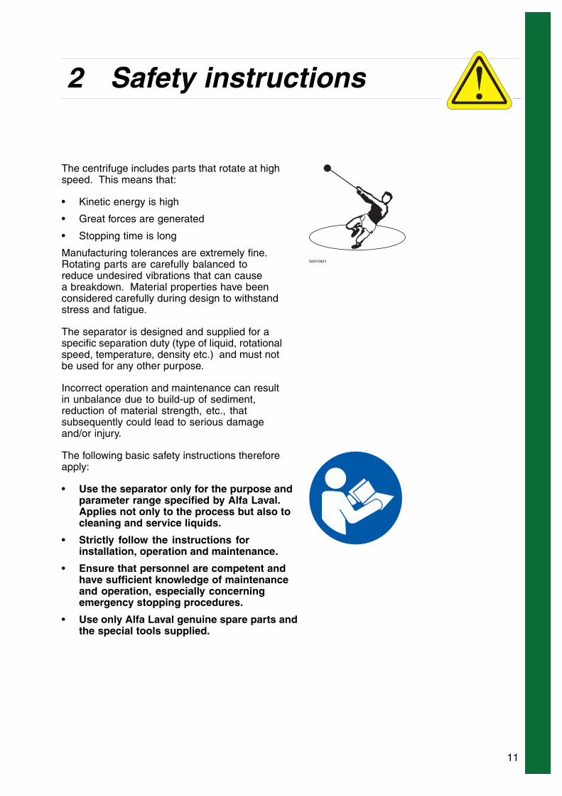
The centrifuge includes parts that rotate at highspeed. This means that:
• Kinetic energy is high
• Great forces are generated
• Stopping time is long
Manufacturing tolerances are extremely fine.Rotating parts are carefully balanced toreduce undesired vibrations that can causea breakdown. Material properties have beenconsidered carefully during design to withstandstress and fatigue.
G0010421
The separator is designed and supplied for aspecific separation duty (type of liquid, rotationalspeed, temperature, density etc.) and must notbe used for any other purpose.
Incorrect operation and maintenance can resultin unbalance due to build-up of sediment,reduction of material strength, etc., thatsubsequently could lead to serious damageand/or injury.
The following basic safety instructions thereforeapply:
• Use the separator only for the purpose andparameter range specified by Alfa Laval.Applies not only to the process but also tocleaning and service liquids.
• Strictly follow the instructions forinstallation, operation and maintenance.
• Ensure that personnel are competent andhave sufficient knowledge of maintenanceand operation, especially concerningemergency stopping procedures.
• Use only Alfa Laval genuine spare parts andthe special tools supplied.
11
2 Safety instructions
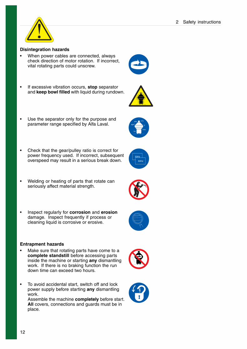
Disintegration hazards• When power cables are connected, always
check direction of motor rotation. If incorrect,vital rotating parts could unscrew.
• If excessive vibration occurs, stop separatorand keep bowl filled with liquid during rundown.
• Use the separator only for the purpose andparameter range specified by Alfa Laval.
kPa m /h3
3o
C
Hz
kg/m
r/min
• Check that the gear/pulley ratio is correct forpower frequency used. If incorrect, subsequentoverspeed may result in a serious break down.
50Hz
60Hz
• Welding or heating of parts that rotate canseriously affect material strength.
• Inspect regularly for corrosion and erosiondamage. Inspect frequently if process orcleaning liquid is corrosive or erosive.
Entrapment hazards• Make sure that rotating parts have come to a
complete standstill before accessing partsinside the machine or starting any dismantlingwork. If there is no braking function the rundown time can exceed two hours.
• To avoid accidental start, switch off and lockpower supply before starting any dismantlingwork.Assemble the machine completely before start.All covers, connections and guards must be inplace.
12
2 Safety instructions
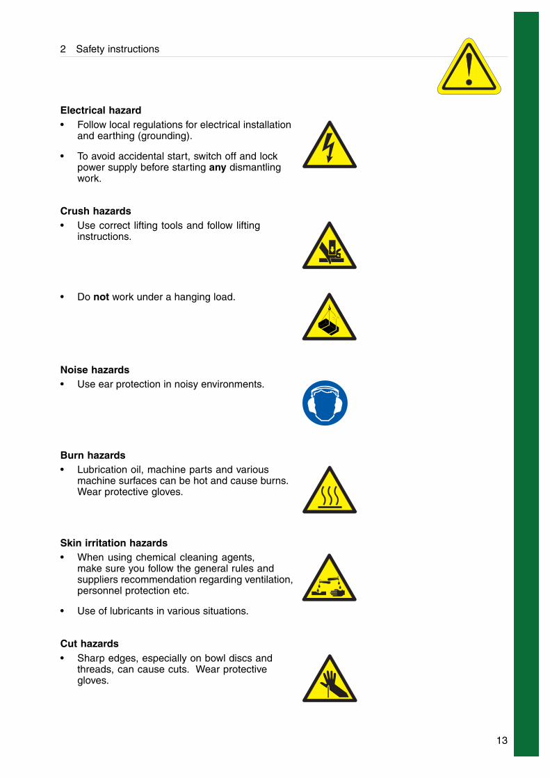
Electrical hazard• Follow local regulations for electrical installation
and earthing (grounding).
• To avoid accidental start, switch off and lockpower supply before starting any dismantlingwork.
Crush hazards• Use correct lifting tools and follow lifting
instructions.
• Do not work under a hanging load.
Noise hazards• Use ear protection in noisy environments.
Burn hazards• Lubrication oil, machine parts and various
machine surfaces can be hot and cause burns.Wear protective gloves.
Skin irritation hazards• When using chemical cleaning agents,
make sure you follow the general rules andsuppliers recommendation regarding ventilation,personnel protection etc.
• Use of lubricants in various situations.
Cut hazards• Sharp edges, especially on bowl discs and
threads, can cause cuts. Wear protectivegloves.
13
2 Safety instructions
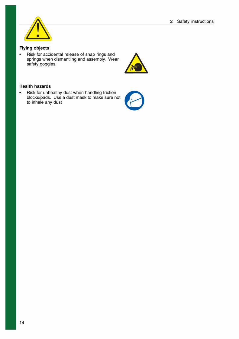
Flying objects• Risk for accidental release of snap rings and
springs when dismantling and assembly. Wearsafety goggles.
Health hazards• Risk for unhealthy dust when handling friction
blocks/pads. Use a dust mask to make sure notto inhale any dust
14
2 Safety instructions
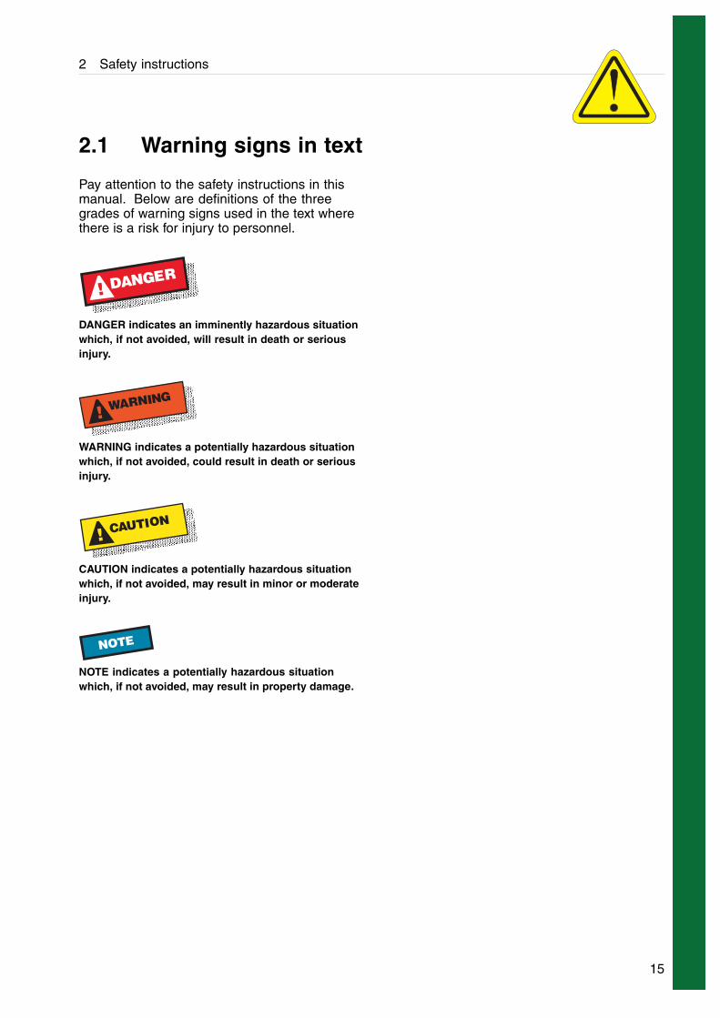
2.1 Warning signs in text
Pay attention to the safety instructions in thismanual. Below are definitions of the threegrades of warning signs used in the text wherethere is a risk for injury to personnel.
D! ANGER
DANGER indicates an imminently hazardous situationwhich, if not avoided, will result in death or seriousinjury.
! WARNING
WARNING indicates a potentially hazardous situationwhich, if not avoided, could result in death or seriousinjury.
! CAUTION
CAUTION indicates a potentially hazardous situationwhich, if not avoided, may result in minor or moderateinjury.
NOTE
NOTE indicates a potentially hazardous situationwhich, if not avoided, may result in property damage.
15
2 Safety instructions
2.2 Environmental issues
Unpacking
Packing material consists of wood, plastics,cardboard boxes and in some cases metalstraps.
Wood and cardboard boxes can be reused,recycled or used for energy recovery.
Plastics should be recycled or burnt at alicensed waste incineration plant.
Metal straps should be sent for materialrecycling.
Maintenance
During maintenance oil and wear parts in themachine are replaced.
Oil must be taken care of in agreement withlocal regulations.
Rubber and plastics should be burnt at alicensed waste incineration plant. If not availablethey should be disposed to a suitable licensedland fill site.
Bearings and other metal parts should be sentto a licensed handler for material recycling.
Seal rings and friction linings should bedisposed to a licensed land fill site. Check yourlocal regulations.
Worn out or defected electronic parts should besent to a licensed handler for material recycling.
16
2 Safety instructions
2.3 Requirements of personnel
Only skilled or instructed persons are allowedto operate the machine, e.g. operating andmaintenance staff.
• Skilled person: A person with technicalknowledge or sufficient experience to enablehim or her to perceive risks and to avoid hazardswhich electricity/mechanics can create.
• Instructed person: A person adequatelyadvised or supervised by a skilled person toenable him or her to perceive risks and to avoidhazards which electricity/mechanics can create.
In some cases special skilled personnel mayneed to be hired, like electricians and others.In some of these cases the personnel has tobe certified according to local regulations withexperience of similar types of work.
2.4 Remote start
If the separator is operated from a remoteposition where the separator cannot be seenor heard the power isolation device shall beequipped with an interlock device to prevent thata remote start command could result in liquidbeing fed to the separator when it is shut downfor service.
The first start after the separator has been takenapart or been standing still for a long time shallalways be manually supervised locally.
17

2 Safety instructions
3 Basic principles of separation
3.1 Introduction
The purpose of separation can be:
• to free a liquid of solid particles,
• to separate two mutually insoluble liquids withdifferent densities while removing any solidspresents at the same time,
• to separate and concentrate solid particles froma liquid.
3.2 Separation by gravity
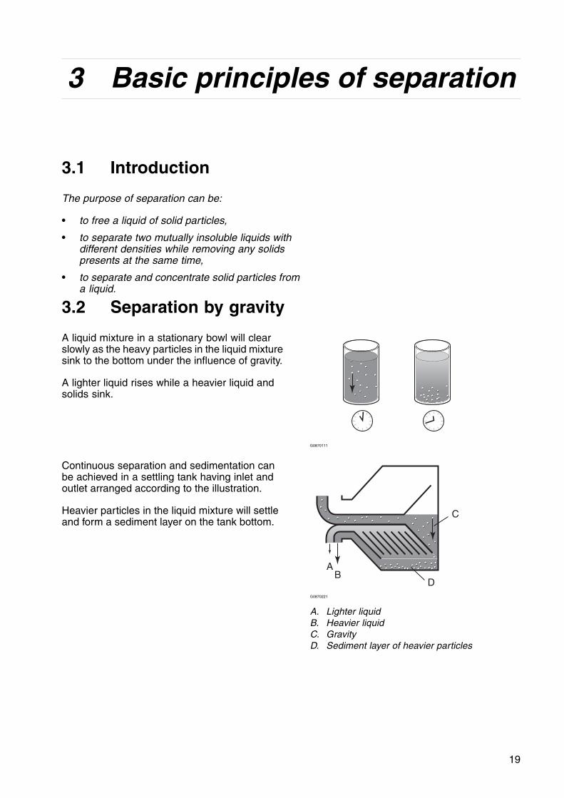
A liquid mixture in a stationary bowl will clearslowly as the heavy particles in the liquid mixturesink to the bottom under the influence of gravity.
A lighter liquid rises while a heavier liquid andsolids sink.
G0870111
Continuous separation and sedimentation canbe achieved in a settling tank having inlet andoutlet arranged according to the illustration.
Heavier particles in the liquid mixture will settleand form a sediment layer on the tank bottom.
AB
C
DG0870221
A. Lighter liquidB. Heavier liquidC. GravityD. Sediment layer of heavier particles
19

3.4 Separating temperatures 3 Basic principles of separation
3.3 Centrifugal separation
In a rapidly rotating bowl, the force of gravityis replaced by centrifugal force, which can bethousands of times greater.
Separation and sedimentation is continuous andhappens very quickly.
The centrifugal force in the separator bowl canachieve in a few seconds what takes manyhours in a tank under influence of gravity.
The separation efficiency is influencedby changes in the viscosity, separatingtemperatures and in throughput.
AB
CG0870321
A. Lighter liquidB. Heavier liquidC. Centrifugal force
3.4 Separating temperatures
For some types of process liquids a highseparating temperature will normally increasethe separation capacity. The temperatureinfluences viscosity and density and should bekept constant throughout the separation.
Viscosity Density differenceViscosity is a fluids resistance against movement.Low viscosity facilitates separation. Viscosity canbe reduced by heating.
Density is mass per volume unit. The greater thedensity difference between the two liquids, theeasier the separation. The density difference canbe increased by heating.
A B
G10348k1
A. High viscosityB. Low viscosity
A B
G10348j1
A. High density (with low temperature)B. Low density (with high temperature)
20
4 Design and function
1
2
3 4
5
6
7
G08707A1
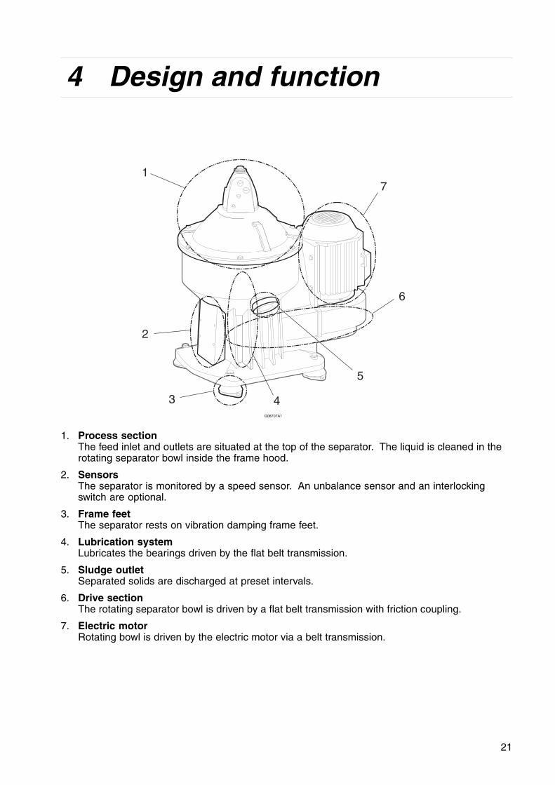
1. Process sectionThe feed inlet and outlets are situated at the top of the separator. The liquid is cleaned in therotating separator bowl inside the frame hood.
2. SensorsThe separator is monitored by a speed sensor. An unbalance sensor and an interlockingswitch are optional.
3. Frame feetThe separator rests on vibration damping frame feet.
4. Lubrication systemLubricates the bearings driven by the flat belt transmission.
5. Sludge outletSeparated solids are discharged at preset intervals.
6. Drive sectionThe rotating separator bowl is driven by a flat belt transmission with friction coupling.
7. Electric motorRotating bowl is driven by the electric motor via a belt transmission.
21

4.1 Overview 4 Design and function
4.1 Overview
The separator comprises a process section anda drive section powered by an electric motor.
The separator frame comprises a lower bodyand a frame hood. The motor is attached to theframe. The frame feet dampen vibration.
The bottom part of the separator contains a flatbelt transmission, a centrifugal clutch and avertical spindle. The lower body also containsan oil sump for lubrication of spindle bearings.
The frame hood contains the processing partsof the separator; the inlets, outlets and piping.
The process liquid is cleaned in the separatorbowl. The bowl is fitted on the upper part of avertical spindle and rotates at high speed insidethe frame hood. The bowl also contains thedischarge mechanism which empties the sludgeduring operation.
A speed sensor, and the optional unbalancesensor and lock switch, are parts of theequipment for monitoring the separatorfunctions.
22

4 Design and function 4.2 Drive section
4.2 Drive section
The separator bowl is driven by an electricmotor via a belt transmission. The belt pulley onthe motor shaft includes a centrifugal clutch.
The centrifugal clutch (2) with friction padsensures a gentle start and smooth acceleration,and at the same time prevents overloading ofthe belt and motor.
To reduce bearing wear and the transmissionof bowl vibrations to the frame and foundation,the top bearing of the bowl spindle is mountedin a spring dampened bearing seat (3). Thebearings on the spindle are lubricated by theoil spray produced by an oil mist generator (4)mounted on the lower end of the spindle.
The flat belt (1) transmission has a ratiowhich increases the bowl speed several timescompared with the motor speed.
23
1
4
g08707B1
1. Flat belt2. Centrifugal clutch3. Spring dampened bearing seat4. Oil mist generator
23
4.3 Process section 4 Design and function
4.3 Process section
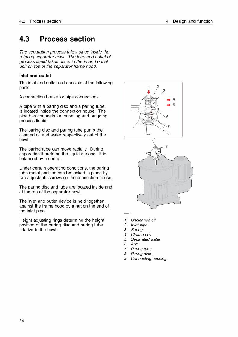
The separation process takes place inside therotating separator bowl. The feed and outlet ofprocess liquid takes place in the in and outletunit on top of the separator frame hood.
Inlet and outlet
The inlet and outlet unit consists of the followingparts:
A connection house for pipe connections.
A pipe with a paring disc and a paring tubeis located inside the connection house. Thepipe has channels for incoming and outgoingprocess liquid.
The paring disc and paring tube pump thecleaned oil and water respectively out of thebowl.
The paring tube can move radially. Duringseparation it surfs on the liquid surface. It isbalanced by a spring.
Under certain operating conditions, the paringtube radial position can be locked in place bytwo adjustable screws on the connection house.
The paring disc and tube are located inside andat the top of the separator bowl.
The inlet and outlet device is held togetheragainst the frame hood by a nut on the end ofthe inlet pipe.
Height adjusting rings determine the heightposition of the paring disc and paring tuberelative to the bowl.
1 2
3
4
5
6
7
8
9
G08861a1
1. Uncleaned oil2. Inlet pipe3. Spring4. Cleaned oil5. Separated water6. Arm7. Paring tube8. Paring disc9. Connecting housing
24
4 Design and function 4.3 Process section
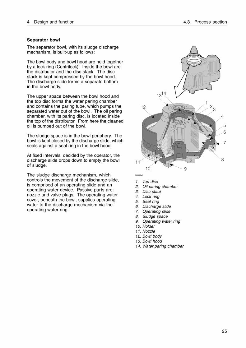
Separator bowl
The separator bowl, with its sludge dischargemechanism, is built-up as follows:
The bowl body and bowl hood are held togetherby a lock ring (Centrilock). Inside the bowl arethe distributor and the disc stack. The discstack is kept compressed by the bowl hood.The discharge slide forms a separate bottomin the bowl body.
The upper space between the bowl hood andthe top disc forms the water paring chamberand contains the paring tube, which pumps theseparated water out of the bowl. The oil paringchamber, with its paring disc, is located insidethe top of the distributor. From here the cleanedoil is pumped out of the bowl.
The sludge space is in the bowl periphery. Thebowl is kept closed by the discharge slide, whichseals against a seal ring in the bowl hood.
At fixed intervals, decided by the operator, thedischarge slide drops down to empty the bowlof sludge.
The sludge discharge mechanism, whichcontrols the movement of the discharge slide,is comprised of an operating slide and anoperating water device. Passive parts are:nozzle and valve plugs. The operating watercover, beneath the bowl, supplies operatingwater to the discharge mechanism via theoperating water ring.
12
3
4
5
6
7
8
910
11
12
1314
G08869a1
1. Top disc2. Oil paring chamber3. Disc stack4. Lock ring5. Seal ring6. Discharge slide7. Operating slide8. Sludge space9. Operating water ring10. Holder11. Nozzle12. Bowl body13. Bowl hood14. Water paring chamber
25
4.4 Sensors and indicators 4 Design and function
4.4 Sensors and indicators
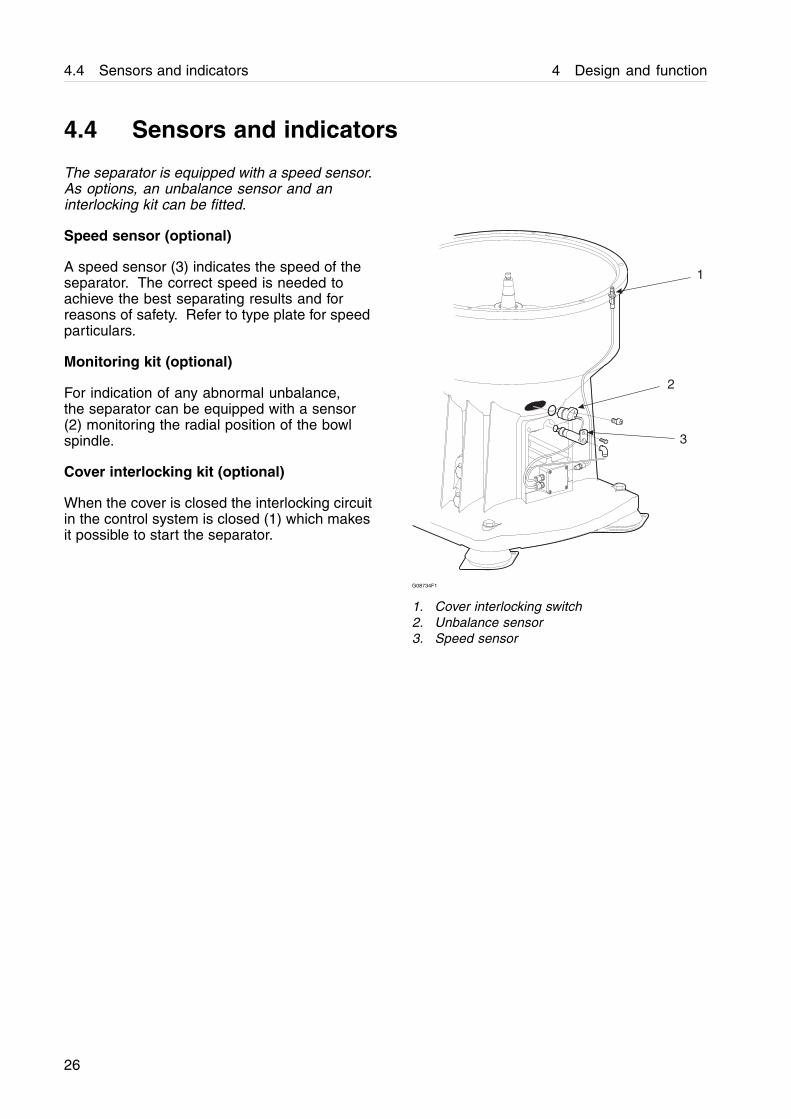
The separator is equipped with a speed sensor.As options, an unbalance sensor and aninterlocking kit can be fitted.
Speed sensor (optional)
A speed sensor (3) indicates the speed of theseparator. The correct speed is needed toachieve the best separating results and forreasons of safety. Refer to type plate for speedparticulars.
Monitoring kit (optional)
For indication of any abnormal unbalance,the separator can be equipped with a sensor(2) monitoring the radial position of the bowlspindle.
Cover interlocking kit (optional)
When the cover is closed the interlocking circuitin the control system is closed (1) which makesit possible to start the separator.
1
2
3
G08734F1
1. Cover interlocking switch2. Unbalance sensor3. Speed sensor
26
4 Design and function 4.5 Separating function
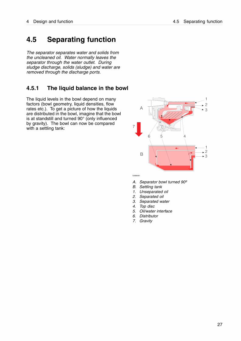
4.5 Separating function
The separator separates water and solids fromthe uncleaned oil. Water normally leaves theseparator through the water outlet. Duringsludge discharge, solids (sludge) and water areremoved through the discharge ports.
4.5.1 The liquid balance in the bowl
The liquid levels in the bowl depend on manyfactors (bowl geometry, liquid densities, flowrates etc.). To get a picture of how the liquidsare distributed in the bowl, imagine that the bowlis at standstill and turned 90° (only influencedby gravity). The bowl can now be comparedwith a settling tank:
1
2
3
1
2
3
6 5 4
7
A
B
G0886481
A. Separator bowl turned 90ºB. Settling tank1. Unseparated oil2. Separated oil3. Separated water4. Top disc5. Oil/water interface6. Distributor7. Gravity
27
4.5 Separating function 4 Design and function
4.5.2 Liquid flow
Unseparated oil is fed into the bowl through theinlet pipe and travels via the distributor towardsthe periphery of the bowl.
When the oil reaches slots in the distributor, itrises through the channels formed by the discstack, where it is evenly distributed.
The oil is continuously cleaned as it travelstowards the centre of the bowl. When thecleaned oil leaves the disc stack, it flows througha number of holes in the distributor and entersthe oil paring chamber. From here it is pumpedby the oil paring disc, and leaves the bowlthrough the oil outlet. Separated water, sludgeand solid particles, which are heavier than theoil, are forced towards the periphery of the bowland collect in the sludge space.
The space between the bowl hood and top disc,as well as the water paring chamber, is filledwith oil, which is distributed over the entirecircumference via the grooves in the top disc.
During normal operation-, the water drain valvein the water outlet is closed.
28
4 Design and function 4.5 Separating function
4.5.3 Discharge of sludge and water (ALCAP™ concept)
As the sludge space fills up and water entersthe disc stack, traces of water will escape withthe cleaned oil. The increase of water content inthe cleaned oil is the sign of reduced separationefficiency.
This condition is monitored by the processcontrol system, and water is removed from thebowl when maximum levels are recorded.
The water is removed by either of two ways:
• The water drain valve opens and the waterleaves the bowl through the water outlet.
• Through the sludge ports at sludge discharge.
Which way is decided by the process controlsystem.
29
4.5 Separating function 4 Design and function
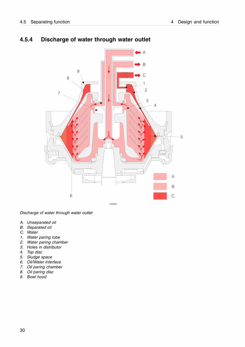
4.5.4 Discharge of water through water outlet
A
B
C
1
2
3
4
5
6
7
8
9
A
B
C
G08862b1
Discharge of water through water outlet
A. Unseparated oilB. Separated oilC. Water1. Water paring tube2. Water paring chamber3. Holes in distributor4. Top disc5. Sludge space6. Oil/Water interface7. Oil paring chamber8. Oil paring disc9. Bowl hood
30
5 Operating instructions
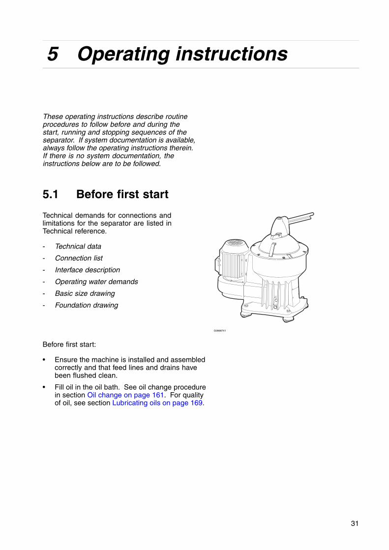
These operating instructions describe routineprocedures to follow before and during thestart, running and stopping sequences of theseparator. If system documentation is available,always follow the operating instructions therein.If there is no system documentation, theinstructions below are to be followed.
5.1 Before first start
Technical demands for connections andlimitations for the separator are listed inTechnical reference.
- Technical data
- Connection list
- Interface description
- Operating water demands
- Basic size drawing
- Foundation drawing
G0868741
Before first start:
• Ensure the machine is installed and assembledcorrectly and that feed lines and drains havebeen flushed clean.
• Fill oil in the oil bath. See oil change procedurein section Oil change on page 161. For qualityof oil, see section Lubricating oils on page 169.
31
5.1 Before first start 5 Operating instructions
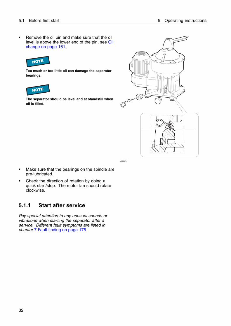
• Remove the oil pin and make sure that the oillevel is above the lower end of the pin, see Oilchange on page 161.
NOTE
Too much or too little oil can damage the separatorbearings.
NOTE
The separator should be level and at standstill whenoil is filled.
g08687h1
• Make sure that the bearings on the spindle arepre-lubricated.
• Check the direction of rotation by doing aquick start/stop. The motor fan should rotateclockwise.
5.1.1 Start after service
Pay special attention to any unusual sounds orvibrations when starting the separator after aservice. Different fault symptoms are listed inchapter 7 Fault finding on page 175.
32

5 Operating instructions 5.2 Normal operation
5.2 Normal operation
5.2.1 Before normal start
To achieve the best separation results, the bowlshould be in a clean condition.
1. Check:
- that all couplings and connections (1) aresecurely tightened to prevent leakages. Leakinghot liquid can cause burns.
- that the lock nut (2) is fully tightened. Do notforget the washer.
- that all frame hood bolts (3) as well as the beltcover are fully tightened.
- the direction of rotation by doing a quickstart/stop. The motor fan (4) should rotateclockwise
- the oil bath level and top up if necessary.
NOTE
The separator should be level and at standstill whenoil is filled.
! CAUTION
If power cable polarity has been reversed, theseparator will rotate in reverse, and vital rotating partscan loosen.
! CAUTION
Disintegration hazardAfter change of feed the sludge discharge intervalmust be adjusted. Breakdown may result if theintervals between discharges are too long.
1
2
3
4
G0871491
33
5.2 Normal operation 5 Operating instructions
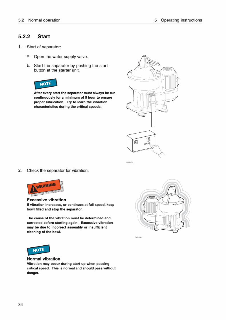
5.2.2 Start
1. Start of separator:
a. Open the water supply valve.
b. Start the separator by pushing the startbutton at the starter unit.
NOTE
After every start the separator must always be runcontinuously for a minimum of 5 hour to ensureproper lubrication. Try to learn the vibrationcharacteristics during the critical speeds.
RO
I
G08717c1
2. Check the separator for vibration.
! WARNING
Excessive vibrationIf vibration increases, or continues at full speed, keepbowl filled and stop the separator.
The cause of the vibration must be determined andcorrected before starting again! Excessive vibrationmay be due to incorrect assembly or insufficientcleaning of the bowl.
G0871881
NOTE
Normal vibrationVibration may occur during start up when passingcritical speed. This is normal and should pass withoutdanger.
34
5 Operating instructions 5.2 Normal operation
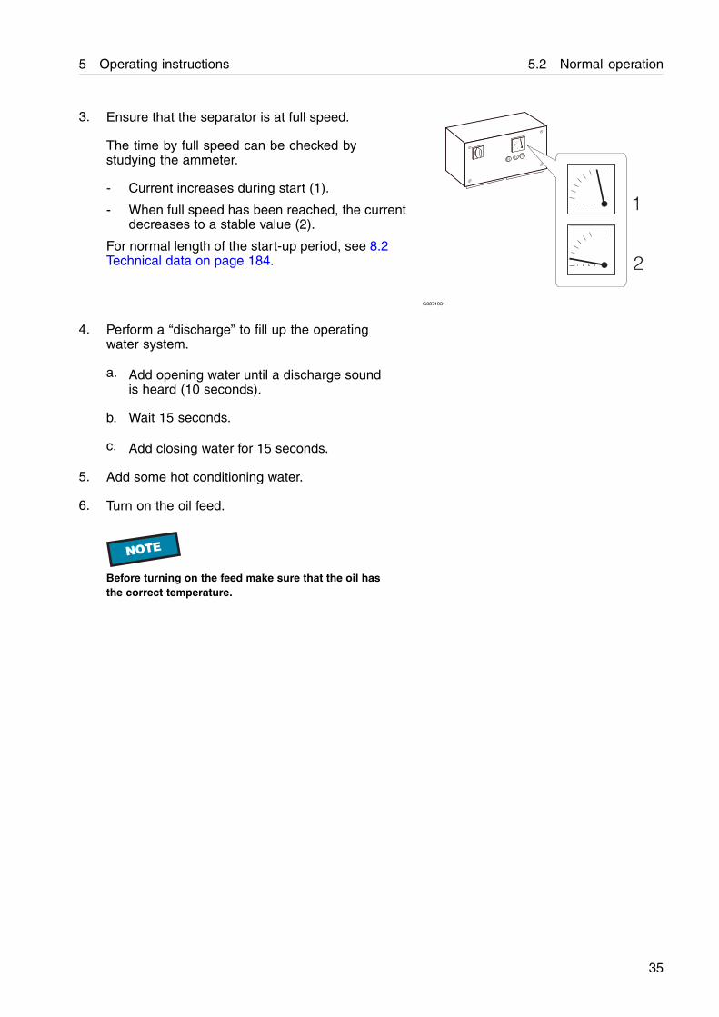
3. Ensure that the separator is at full speed.
The time by full speed can be checked bystudying the ammeter.
- Current increases during start (1).
- When full speed has been reached, the currentdecreases to a stable value (2).
For normal length of the start-up period, see 8.2Technical data on page 184.
RO
I
1
2
G0871931
4. Perform a “discharge” to fill up the operatingwater system.
a. Add opening water until a discharge soundis heard (10 seconds).
b. Wait 15 seconds.
c. Add closing water for 15 seconds.
5. Add some hot conditioning water.
6. Turn on the oil feed.
NOTE
Before turning on the feed make sure that the oil hasthe correct temperature.
35
5.2 Normal operation 5 Operating instructions
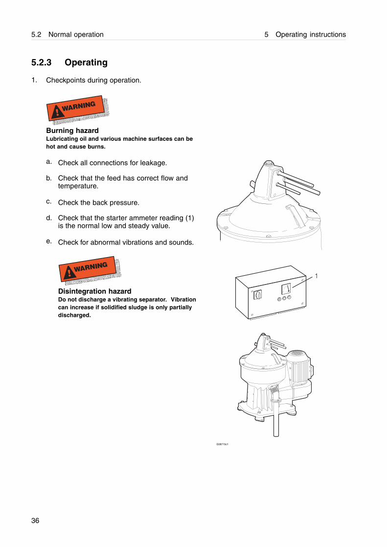
5.2.3 Operating
1. Checkpoints during operation.
! WARNING
Burning hazardLubricating oil and various machine surfaces can behot and cause burns.
a. Check all connections for leakage.
b. Check that the feed has correct flow andtemperature.
c. Check the back pressure.
d. Check that the starter ammeter reading (1)is the normal low and steady value.
e. Check for abnormal vibrations and sounds.
! WARNING
Disintegration hazardDo not discharge a vibrating separator. Vibrationcan increase if solidified sludge is only partiallydischarged.
R O 1
1
G08715c1
36
5 Operating instructions 5.2 Normal operation
5.2.3.1 Sludge discharge
1. Turn off the oil feed.
2. Perform a displacement of the oil by adding hotwater (not more than bowl volume).
3. Perform a sludge discharge.
a. Add opening water until a discharge soundis heard (max. 3 seconds).
b. Wait 15 seconds.
c. Add closing water for 15 seconds.
4. Turn on the oil feed.
NOTE
Before turning on the feed, make sure that the oil hasthe correct temperature.
37
5.2 Normal operation 5 Operating instructions
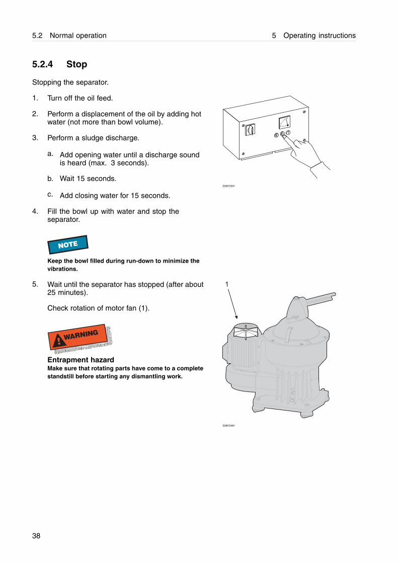
5.2.4 Stop
Stopping the separator.
1. Turn off the oil feed.
2. Perform a displacement of the oil by adding hotwater (not more than bowl volume).
3. Perform a sludge discharge.
a. Add opening water until a discharge soundis heard (max. 3 seconds).
b. Wait 15 seconds.
c. Add closing water for 15 seconds.
RO
I
G0872331
4. Fill the bowl up with water and stop theseparator.
NOTE
Keep the bowl filled during run-down to minimize thevibrations.
5. Wait until the separator has stopped (after about25 minutes).
Check rotation of motor fan (1).
! WARNING
Entrapment hazardMake sure that rotating parts have come to a completestandstill before starting any dismantling work.
1
G0872491
38

5 Operating instructions 5.3 Emergency stop
5.3 Emergency stop
1. If the separator vibrates excessively push theemergency stop button (1).
NOTE
Keep the bowl filled during run-down to minimize thevibrations.
1
G0871281
2. Evacuate the room.
! WARNING
Disintegration hazardNever discharge a vibrating separator.
! WARNING
Entrapment hazardMake sure that rotating parts have come to a completestandstill before starting any dismantling work.
! WARNING
Disintegration hazardAfter an emergency stop, the cause of the fault mustbe identified.
If all parts have been checked and the cause notfound, contact Alfa Laval for advice before restartingthe separator.
EXIT
G0871381
39

5.3 Emergency stop 5 Operating instructions
6 Service, dismantling, assembly
6.1 Periodic maintenance
Periodic (preventive) maintenance reduces therisk of unexpected stoppages and breakdowns.Follow the maintenance log in this chapter inorder to facilitate the periodic maintenance.
6.1.1 Maintenance intervals
The following directions for periodic maintenancegive a brief description of parts to be cleaned,checked and renewed at different maintenanceintervals. The maintenance log for eachmaintenance interval, see page 46, gives adetailed list of actions to be performed.
Inspection [i]
An Inspection consists of an overhaul of theseparator bowl, inlet/outlet and operating waterdevice at max. 6 months or 4000 operatinghours.Seals in bowl and gaskets in inlet/outlet deviceare renewed.
Overhaul [o]
An Overhaul consists of an overhaul of thecomplete separator (including separator bowl,inlet/outlet and operating device) at max. 18months or 12000 operating hours. Seals,bearings, friction blocks and flat belt in theseparator are renewed.
Oil change
The oil should be changed every 4000 hours,or at least once every year if the total number ofoperating hours is less than 4000 hours/year.
41
6.1 Periodic maintenance 6 Service, dismantling, assembly
Electric motor
Motor service consists of an overhaul of themotor at max. 36 months or 24000 operatinghours.Bearings, fan, seals and washers for the motorare renewed.
Ancillary
Verify correct flow at inspection service overhaulwater valveblock at least every 36 months.
42

6 Service, dismantling, assembly 6.1 Periodic maintenance
6.1.2 Maintenance procedure
At each Inspection and/or Overhaul, take a copyof the maintenance log and use it to make notesduring the service.
An inspection and overhaul should be carriedout as follows:
1. Dismantle the parts as described in 6.3Dismantling on page 49.
Place the separator parts on clean, soft surfacessuch as pallets.
2. Inspect and clean the dismantled separatorparts according to the maintenance log anddescription in 6.4 Actions before assembly onpage 99.
3. Fit all the parts delivered in the service kit whileassembling the separator as described in 6.5Assembly on page 107.
4. When the separator is assembled, makefinal checks described in 6.5.7 Actions afterassembly on page 159.
! WARNING
Disintegration hazardSeparator parts that are either missing, worn beyondtheir safe limits or incorrectly assembled, may causesevere damage or fatal injury.
! CAUTION
Burn and corrode hazardEscaping hot and/or corroding process material, whichcan be hazardous, may still remain in the separatorafter stop.
43
6.1 Periodic maintenance 6 Service, dismantling, assembly
The use of service symbols in the dismantling/assemblyinstructions
Parts that have to be renewed from the servicekits (see below) are marked [i] and/or [o] in theassembly instructions.
Example
a. Fit the O-ring [i].
When dismantling and assembling between theservice periods, some procedures do not haveto be carried out. These procedures are marked[i] and/or [o].
All symbols used in the instructions refer toactivities mentioned in the maintenance logs.
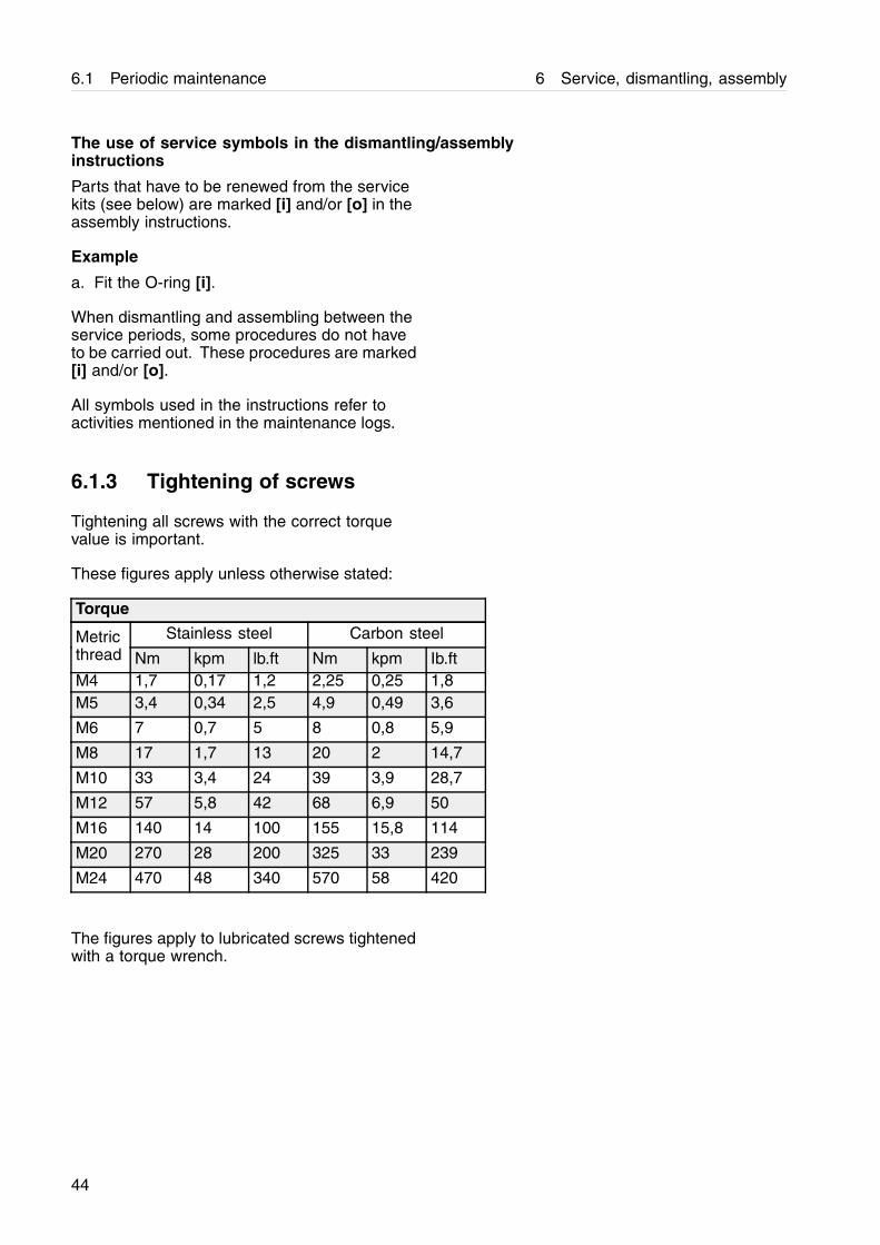
6.1.3 Tightening of screws
Tightening all screws with the correct torquevalue is important.
These figures apply unless otherwise stated:
Torque
Stainless steel Carbon steelMetricthread Nm kpm lb.ft Nm kpm Ib.ftM4 1,7 0,17 1,2 2,25 0,25 1,8M5 3,4 0,34 2,5 4,9 0,49 3,6
M6 7 0,7 5 8 0,8 5,9
M8 17 1,7 13 20 2 14,7
M10 33 3,4 24 39 3,9 28,7
M12 57 5,8 42 68 6,9 50
M16 140 14 100 155 15,8 114
M20 270 28 200 325 33 239
M24 470 48 340 570 58 420
The figures apply to lubricated screws tightenedwith a torque wrench.
44
6 Service, dismantling, assembly 6.1 Periodic maintenance
6.1.4 Service kits
Special service kits are available for Inspection,Overhaul and Motor.
For other services, a Support kit is available.Spare parts not included in the Support kit haveto be ordered separately.
Note that the parts for Inspection are includedin the Overhaul kit.
The contents of the kits are described in theSpare Parts Catalogue.
NOTE
Always use Alfa Laval genuine parts as otherwise thewarranty may become invalid. Alfa Laval takes noresponsibility for the safe operation of the equipmentif non-genuine spare parts are used.
! WARNING
Disintegration hazardUse of imitation spare parts may cause severe damage.
6.1.5 Cleaning
CIP (Cleaning In Place)
To prolong the intervals between manualcleaning of the separator the use of CIP togetherwith repeated discharges can be used.
Some CIP liquids can be corrosive to brass-and aluminium alloy parts which are includedin the separator.
! CAUTION
Use only Alfa Laval recommended CIP liquids.
45
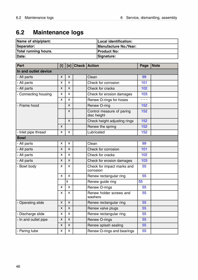
6.2 Maintenance logs 6 Service, dismantling, assembly
6.2 Maintenance logsName of ship/plant: Local identification:Separator: Manufacture No./Year:Total running hours. Product No:Date: Signature:
Part [i] [o] Check Action Page Note
In and outlet device
- All parts x x Clean 99
- All parts x x Check for corrosion 101
- All parts x x Check for cracks 102
- Connecting housing x x Check for erosion damages 103
x x Renew O-rings for hoses - - -
- Frame hood x Renew O-ring 152
x Control measure of paringdisc height
152
x Check height adjusting rings 152
x Renew the spring 152
- Inlet pipe thread x x Lubricated 152
Bowl
- All parts x x Clean 99
- All parts x x Check for corrosion 101
- All parts x x Check for cracks 102
- All parts x x Check for erosion damages 103
- Bowl body x x Check for impact marks andcorrosion
55
x x Renew rectangular ring 55
x Renew guide ring 55
x x Renew O-rings 55
x x Renew holder screws andwashers
55
- Operating slide x x Renew rectangular ring 55
x x Renew valve plugs 55
- Discharge slide x x Renew rectangular ring 55
- In and outlet pipe x x Renew O-rings 55
x x Renew splash sealing 55
- Paring tube x x Renew O-rings and bearings 55
46

6 Service, dismantling, assembly 6.2 Maintenance logs
Part [i] [o] Check Action Page Note
- Lock ring x Check for deformations 55
x Check for impact marks 55
x Check pin not deformed orloose
55
- Bowl hood x x Renew seal ring 55
x x Renew O-ring 55
- Operating water ring x x Renew seal ring and screws 55
Frame
- Frame feet Renew frame feet (includingwashers and screws)
115 Has to beorderedseparately
- Drain and oil fillingholes
x x Renew washers 115
- Oil pin x x Renew O-ring 115
Driving device
- All parts x Clean 99
- All parts x Check for corrosion 101
- All parts x Check for cracks 102
- Bottom bearinghousing
x Renew O-ring 115
- Labyrinth ring holder x Renew labyrinth ring 115
x Renew O-ring 115
- Top bearing housing x Renew springs 115
- Flat belt x Renew flat belt 115
- Bowl spindle x Pre-lubricate and renew ballbearing
115
x Pre-lubricate and renewself-aligning roller bearing
115
x Lubricate the spindle 115
x Measure the radial wobble 115
- Neck bearing cover x Renew O-ring 115
- Deflector ring x Renew O-ring 115
- Water inlet pipe x Renew O-ring 115
- Operating water cover x Renew seal ring and O-ring 115
x Check that operating waterchannel is free from blockage
115
- Fan x Renew O-ring 115
Coupling
- All parts x Clean 99
- All parts x Check for corrosion 101
- All parts x Check for cracks 102
47
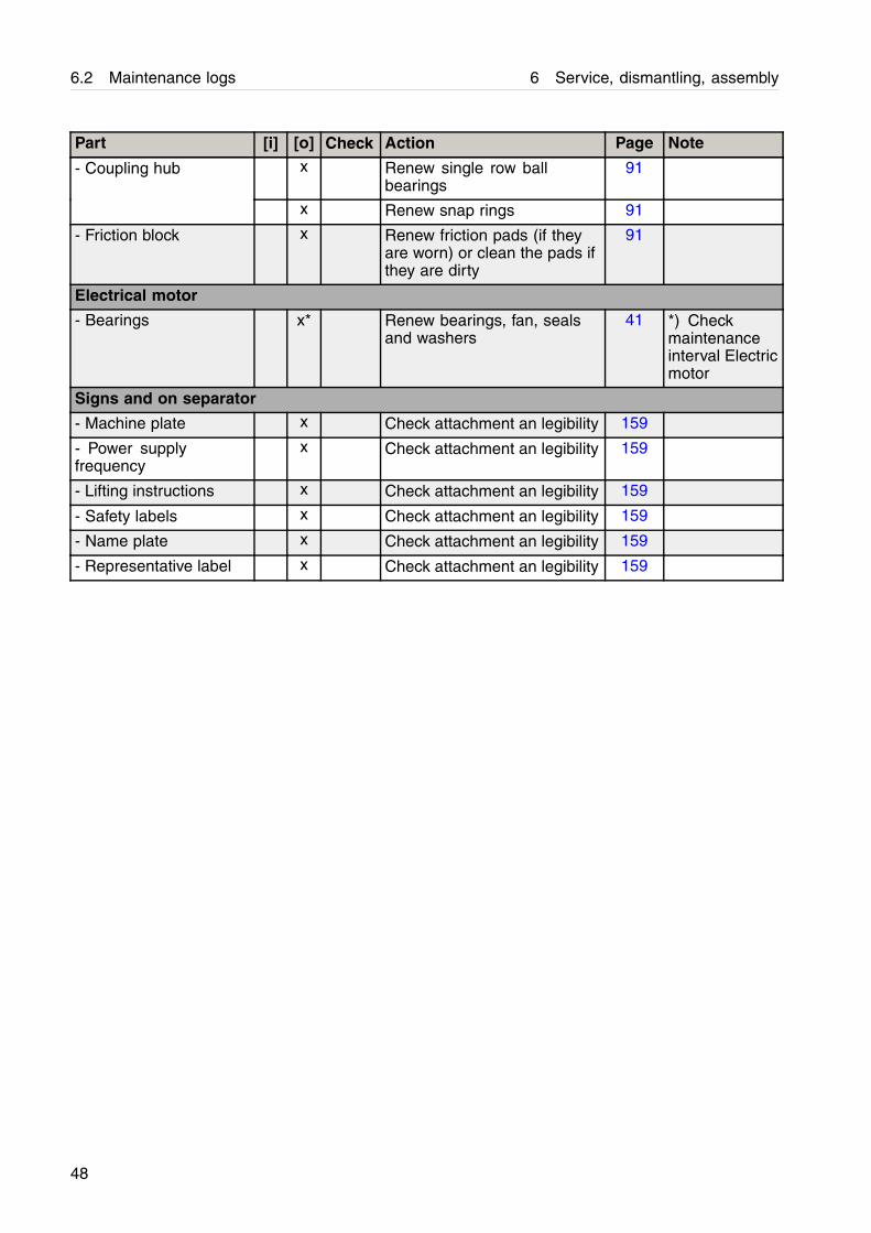
6.2 Maintenance logs 6 Service, dismantling, assembly
Part [i] [o] Check Action Page Note
- Coupling hub x Renew single row ballbearings
91
x Renew snap rings 91
- Friction block x Renew friction pads (if theyare worn) or clean the pads ifthey are dirty
91
Electrical motor
- Bearings x* Renew bearings, fan, sealsand washers
41 *) Checkmaintenanceinterval Electricmotor
Signs and on separator
- Machine plate x Check attachment an legibility 159
- Power supplyfrequency
x Check attachment an legibility 159
- Lifting instructions x Check attachment an legibility 159
- Safety labels x Check attachment an legibility 159
- Name plate x Check attachment an legibility 159
- Representative label x Check attachment an legibility 159
48
6 Service, dismantling, assembly 6.3 Dismantling
6.3 Dismantling
6.3.1 Introduction
The frame hood and heavy bowl parts must belifted by means of a hoist. Position the hoistexactly above the bowl centre. Use a lifting slingand lifting hooks with safety catches.
The parts must be handled carefully. Don’tplace parts directly on the floor, but on a cleanrubber mat, fiberboard or a suitable pallet.
NOTE
For safety reasons, it is essential that all personnelwho work with the separator read this manualthoroughly and completely. Do not allow personnel toclean, assemble, operate or maintain the separatoruntil they have read and fully understood this manual.Ensure that all personnel who operate and servicethe separator are well-trained and knowledgeableconcerning the separator and the work to be carriedout.
6.3.2 Tools
Special tools from the tool kit must be used fordismantling and assembly, as well as Standardtools (not included). The special tools arespecified in the Spare Parts Catalogue and areillustrated at the beginning of each dismantlingsection.
! WARNING
Entrapment hazardTo avoid accidental start, switch off and lock-outpower supply before starting any dismantling work.
Make sure that machine has come to a completestandstill before starting any dismantling work (takesabout 25 minutes from switch off).
49
6.3 Dismantling 6 Service, dismantling, assembly
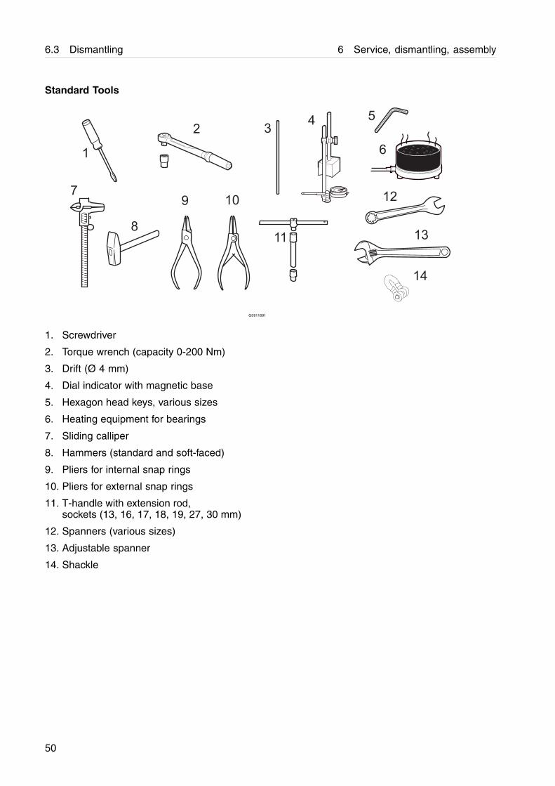
Standard Tools
G0911691
1. Screwdriver
2. Torque wrench (capacity 0-200 Nm)
3. Drift (Ø 4 mm)
4. Dial indicator with magnetic base
5. Hexagon head keys, various sizes
6. Heating equipment for bearings
7. Sliding calliper
8. Hammers (standard and soft-faced)
9. Pliers for internal snap rings
10. Pliers for external snap rings
11. T-handle with extension rod,sockets (13, 16, 17, 18, 19, 27, 30 mm)
12. Spanners (various sizes)
13. Adjustable spanner
14. Shackle
50
6 Service, dismantling, assembly 6.3 Dismantling
6.3.3 Frame hood
G0863351
1
G1019211
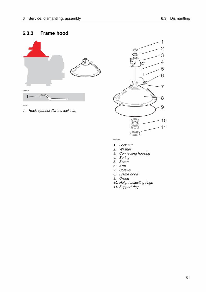
1. Hook spanner (for the lock nut)
G08634n1
1. Lock nut2. Washer3. Connecting housing4. Spring5. Screw6. Arm7. Screws8. Frame hood9. O-ring10. Height adjusting rings11. Support ring
51
6.3 Dismantling 6 Service, dismantling, assembly
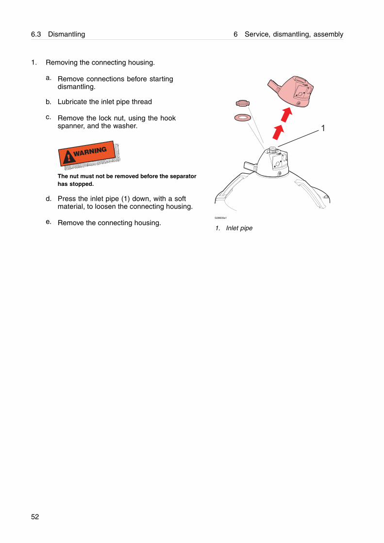
1. Removing the connecting housing.
a. Remove connections before startingdismantling.
b. Lubricate the inlet pipe thread
c. Remove the lock nut, using the hookspanner, and the washer.
! WARNING
The nut must not be removed before the separatorhas stopped.
d. Press the inlet pipe (1) down, with a softmaterial, to loosen the connecting housing.
e. Remove the connecting housing.G08635e1
1. Inlet pipe
52
6 Service, dismantling, assembly 6.3 Dismantling
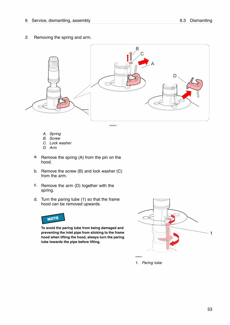
2. Removing the spring and arm.
D
A
BC
G08636m1
A. SpringB. ScrewC. Lock washerD. Arm
a. Remove the spring (A) from the pin on thehood.
b. Remove the screw (B) and lock washer (C)from the arm.
c. Remove the arm (D) together with thespring.
d. Turn the paring tube (1) so that the framehood can be removed upwards.
NOTE
To avoid the paring tube from being damaged andpreventing the inlet pipe from sticking to the framehood when lifting the hood, always turn the paringtube towards the pipe before lifting.
1
G08636J1
1. Paring tube
53
6.3 Dismantling 6 Service, dismantling, assembly
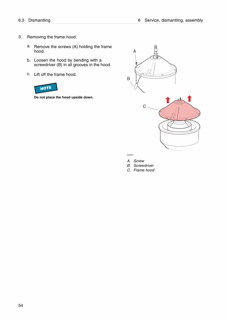
3. Removing the frame hood.
a. Remove the screws (A) holding the framehood.
b. Loosen the hood by bending with ascrewdriver (B) in all grooves in the hood.
c. Lift off the frame hood.
NOTE
Do not place the hood upside down.
A
B
C
G08636I1
A. ScrewB. ScrewdriverC. Frame hood
54
6 Service, dismantling, assembly 6.3 Dismantling
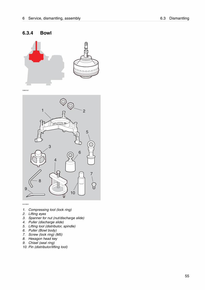
6.3.4 Bowl
G0861621
21
5
63
4
8
7
910
G1019221
1. Compressing tool (lock ring)2. Lifting eyes3. Spanner for nut (nut/discharge slide)4. Puller (discharge slide)5. Lifting tool (distributor, spindle)6. Puller (Bowl body)7. Screw (lock ring) (M5)8. Hexagon head key9. Chisel (seal ring)10. Pin (distributor/lifting tool)
55
6.3 Dismantling 6 Service, dismantling, assembly
1
2
3
6
45
78
9
10
11
12
131415
1617
1819202122
23242527
2829
31
11a
26
30G08626y3
56
6 Service, dismantling, assembly 6.3 Dismantling
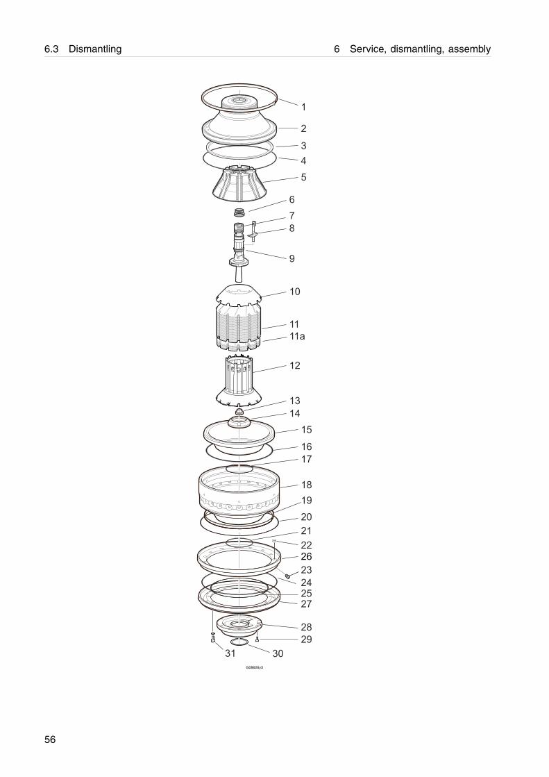
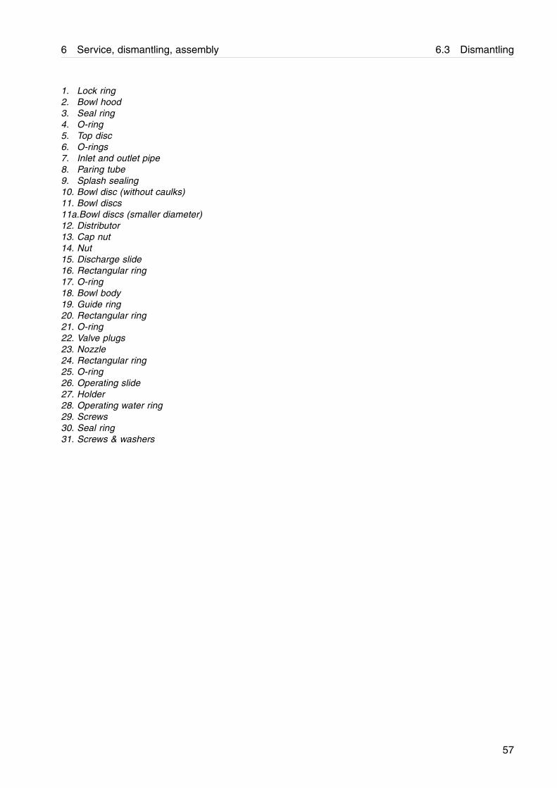
1. Lock ring2. Bowl hood3. Seal ring4. O-ring5. Top disc6. O-rings7. Inlet and outlet pipe8. Paring tube9. Splash sealing10. Bowl disc (without caulks)11. Bowl discs11a.Bowl discs (smaller diameter)12. Distributor13. Cap nut14. Nut15. Discharge slide16. Rectangular ring17. O-ring18. Bowl body19. Guide ring20. Rectangular ring21. O-ring22. Valve plugs23. Nozzle24. Rectangular ring25. O-ring26. Operating slide27. Holder28. Operating water ring29. Screws30. Seal ring31. Screws & washers
57

6.3 Dismantling 6 Service, dismantling, assembly
1. Removing the lock ring.
a. Fit the compressing tool (A).
b. Fit the clamps (C) and the screws (B) tostop.
NOTE
Be sure not to cover the threaded holes for thelock ring.
c. Compress the disc stack by alternatelytightening the inner screws (F) on thecompressing tool in increments of 5 Nm upto a maximum of 15 Nm.
NOTE
If the separator have been out of operation and thebowl is cold, a higher compression torque mightbe required due to oil residue between bowl hoodand bowl body. It these cases a compressiontorque up to 60 Nm can be used to open the bowl.
d. Fit the dismantling screws (D) to thebowl body and press out the lock ringby tightening the screws successivelyaccording to the numbering in the illustration(1-6). Start with the screw (1) nearest to thelock ring end (G), the one without pin (I), andthen continue around until the other end (H)is reached. The lock ring can be removedwhen it has passed the edge of the groove.
e. Remove the lock ring (E) from the groove.
NOTE
Remove the dismantling screws.
A
1
23
4
5
6
B
D
E
C
F
1
G
H
I
G08627B2
A. Compressing toolB. ScrewC. ClampD. Dismantling screwE. Lock ringF. Compressing screwG. Lock ring end without pinH. Lock ring end with pinI. Pin
58

6 Service, dismantling, assembly 6.3 Dismantling
2. Removing the bowl hood.
a. Remove the compressing screws (A).
b. Loosen the screws (B) on the clamp tool.Remove the tool. Remove the lock ring.
NOTE
See removing the bowl hood with optionalhydraulic tool (if purchased) on next page.
c. Fit the compressing tool and the pullerscrews (C). Pull the bowl hood off byscrewing the screws alternately (max. 1/2turn) and gradually increase the momentumevenly until the bowl hood come loose.
NOTE
The bowl hood must be pulled off straight up, inorder not to get stuck.
Recommendation: Take measurements with acalliper around the bowl, between the upper edgeof the bowl body and the bowl hood, to check thatthe bowl hood is being pulled off straight up.
d. Remove the clamps and attach lifting eyes(D) to the compressing tool and lift off thebowl hood using slings and hoist.
! WARNING
Crush hazardThe top disc can adhere to the bowl hood whenlifting. Be careful not to accidentally drop it.
A
B
C
D
G08628J1
A. Compressing screwB. ScrewC. Puller screwD. Lifting eye
59

6.3 Dismantling 6 Service, dismantling, assembly
3. Removing the bowl hood using the hydraulictool (optional).
NOTE
First remove the lock ring according to instructions a-b, on previous page.
a. Fit the larger stud bolt (A) into the in- andoutlet pipe (must rest on the cap nut).
b. Fit the nut (B) and the washer. Make surethat the nut is above the pipe.
c. Fit the stud bolts (C) into the compressingtool (equal length).
d. Fit the hydraulic piston (D) onto the bolt.
e. Fit the holder (E) and fasten with nuts. Makesure that the holder is in a level position (thebowl hood must be pulled off straight up).
f. Attach the hose from the hand pump to thehydraulic oil inlet (F).
Ease off the bowl hood by pumping thehandle on the pump.
NOTE
The bowl hood must be pulled off straight up, inorder not to get stuck.
g. Remove the hydraulic tool and clamps. Fitlifting eyes (G) and lift off the bowl hoodusing slings and hoist.
! WARNING
Crush hazardThe top disc can adhere to the bowl hood whenlifting. Be careful not to accidentally drop it.
G
A F
B
C
D
E
G08628K1
A. Larger stud boltB. Nut and washerC. Stud boltD. Hydraulic pistonE. Holder with nutsF. Oil inletG. Lifting eye
60
6 Service, dismantling, assembly 6.3 Dismantling
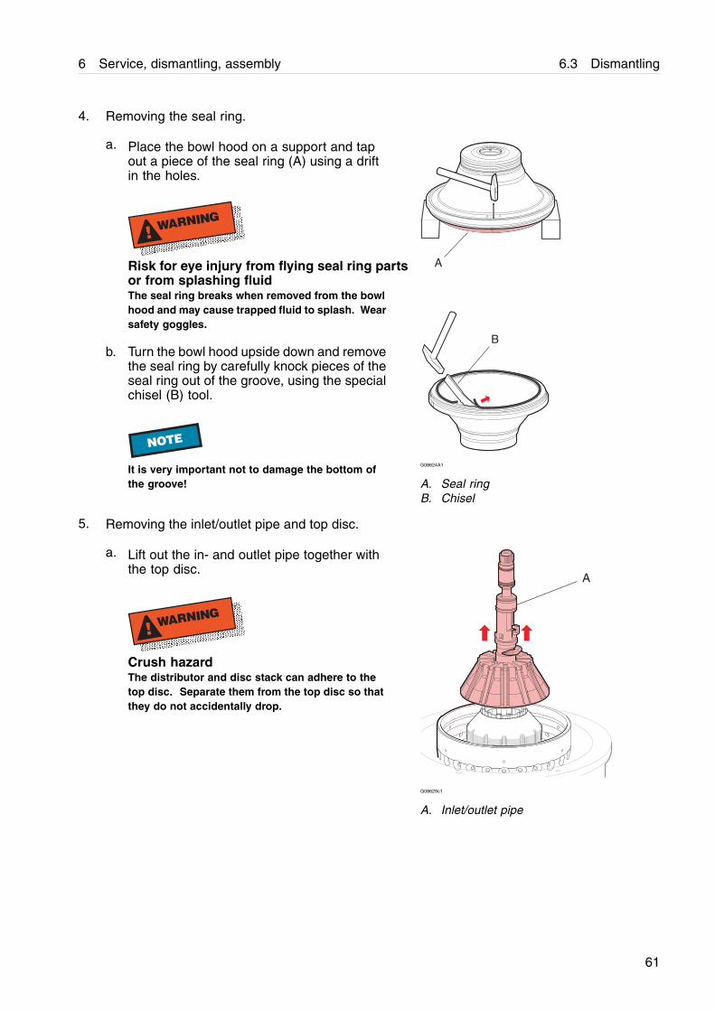
4. Removing the seal ring.
a. Place the bowl hood on a support and tapout a piece of the seal ring (A) using a driftin the holes.
! WARNING
Risk for eye injury from flying seal ring partsor from splashing fluidThe seal ring breaks when removed from the bowlhood and may cause trapped fluid to splash. Wearsafety goggles.
b. Turn the bowl hood upside down and removethe seal ring by carefully knock pieces of theseal ring out of the groove, using the specialchisel (B) tool.
NOTE
It is very important not to damage the bottom ofthe groove!
A
B
G08624A1
A. Seal ringB. Chisel
5. Removing the inlet/outlet pipe and top disc.
a. Lift out the in- and outlet pipe together withthe top disc.
! WARNING
Crush hazardThe distributor and disc stack can adhere to thetop disc. Separate them from the top disc so thatthey do not accidentally drop.
A
G08629c1
A. Inlet/outlet pipe
61
6.3 Dismantling 6 Service, dismantling, assembly
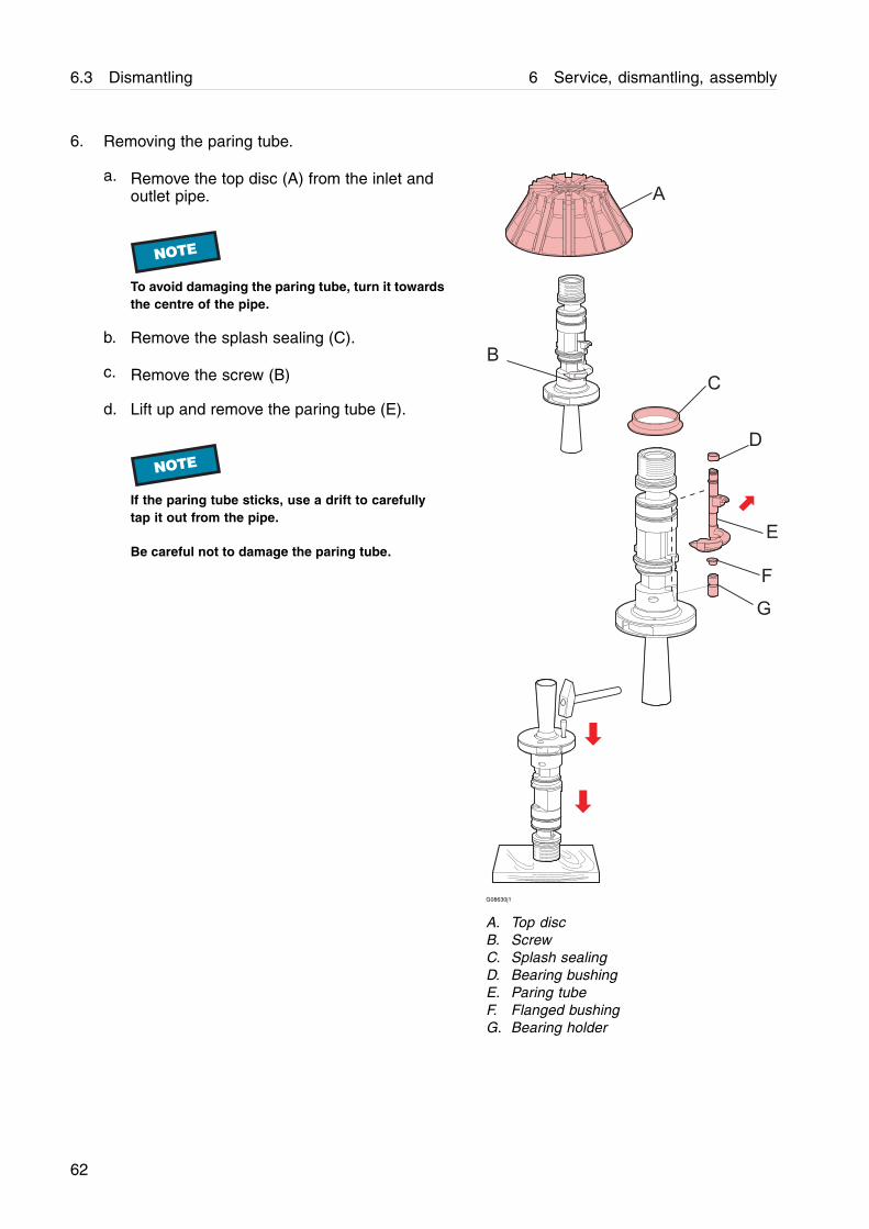
6. Removing the paring tube.
a. Remove the top disc (A) from the inlet andoutlet pipe.
NOTE
To avoid damaging the paring tube, turn it towardsthe centre of the pipe.
b. Remove the splash sealing (C).
c. Remove the screw (B)
d. Lift up and remove the paring tube (E).
NOTE
If the paring tube sticks, use a drift to carefullytap it out from the pipe.
Be careful not to damage the paring tube.
A
C
D
E
F
G
B
G08630j1
A. Top discB. ScrewC. Splash sealingD. Bearing bushingE. Paring tubeF. Flanged bushingG. Bearing holder
62
6 Service, dismantling, assembly 6.3 Dismantling
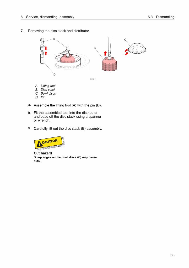
7. Removing the disc stack and distributor.
A
B
C
DG08631C1
A. Lifting toolB. Disc stackC. Bowl discsD. Pin
a. Assemble the lifting tool (A) with the pin (D).
b. Fit the assembled tool into the distributorand ease off the disc stack using a spanneror wrench.
c. Carefully lift out the disc stack (B) assembly.
! CAUTION
Cut hazardSharp edges on the bowl discs (C) may causecuts.
63
6.3 Dismantling 6 Service, dismantling, assembly
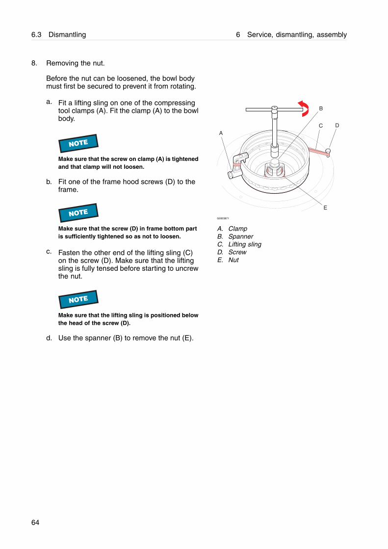
8. Removing the nut.
Before the nut can be loosened, the bowl bodymust first be secured to prevent it from rotating.
a. Fit a lifting sling on one of the compressingtool clamps (A). Fit the clamp (A) to the bowlbody.
NOTE
Make sure that the screw on clamp (A) is tightenedand that clamp will not loosen.
b. Fit one of the frame hood screws (D) to theframe.
NOTE
Make sure that the screw (D) in frame bottom partis sufficiently tightened so as not to loosen.
c. Fasten the other end of the lifting sling (C)on the screw (D). Make sure that the liftingsling is fully tensed before starting to uncrewthe nut.
NOTE
Make sure that the lifting sling is positioned belowthe head of the screw (D).
d. Use the spanner (B) to remove the nut (E).
A
B
C
E
D
G0923871
A. ClampB. SpannerC. Lifting slingD. ScrewE. Nut
64

6 Service, dismantling, assembly 6.3 Dismantling
9. Removing the discharge slide.
a. Fit the lifting tool (A) by pressing the pullerrods (E) towards each other and positionthem into the two slots on the bowl body (F).
Slide metal ring (D) down over bowl nave.
b. Ease off the discharge slide (C) by turningthe central screw (B).
NOTE
If discharge slide is difficult to remove, tap lightlyon outside edge with a soft faced hammer.
c. Lift out the discharge slide (C).
! WARNING
Crush hazardThe ring on the lifting tool must be pusheddown against the discharge slide, otherwise thedischarge slide may come loose from the tool.
B
C
A
DEC
F
E
G0863291
A. Lifting toolB. ScrewC. Discharge slideD. RingE. Puller rodF. Bowl body
65
6.3 Dismantling 6 Service, dismantling, assembly
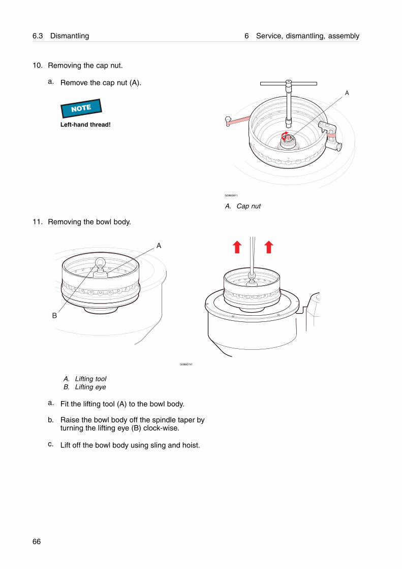
10. Removing the cap nut.
a. Remove the cap nut (A).
NOTE
Left-hand thread!
A
G08606F1
A. Cap nut
11. Removing the bowl body.
A
B
G0860741
A. Lifting toolB. Lifting eye
a. Fit the lifting tool (A) to the bowl body.
b. Raise the bowl body off the spindle taper byturning the lifting eye (B) clock-wise.
c. Lift off the bowl body using sling and hoist.
66
6 Service, dismantling, assembly 6.3 Dismantling
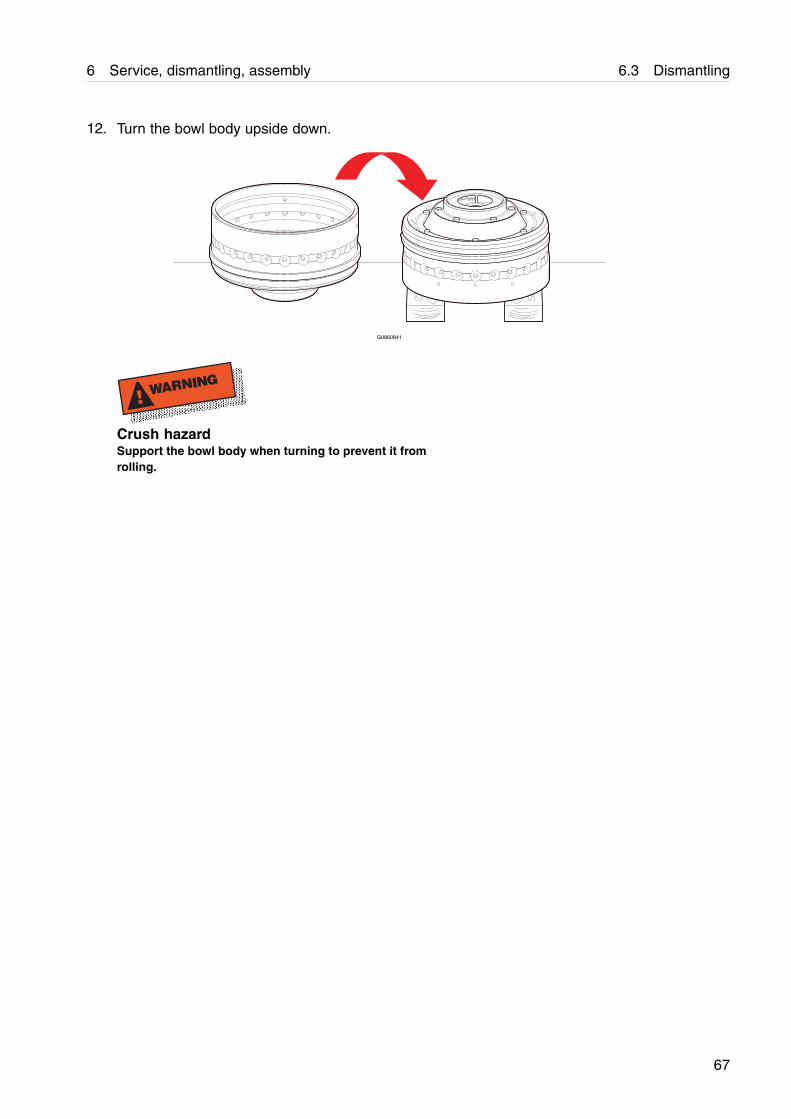
12. Turn the bowl body upside down.
G0860841
! WARNING
Crush hazardSupport the bowl body when turning to prevent it fromrolling.
67
6.3 Dismantling 6 Service, dismantling, assembly
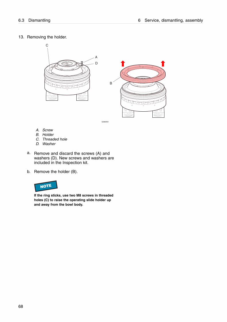
13. Removing the holder.
B
A
C
D
G0860951
A. ScrewB. HolderC. Threaded holeD. Washer
a. Remove and discard the screws (A) andwashers (D). New screws and washers areincluded in the Inspection kit.
b. Remove the holder (B).
NOTE
If the ring sticks, use two M8 screws in threadedholes (C) to raise the operating slide holder upand away from the bowl body.
68
6 Service, dismantling, assembly 6.3 Dismantling
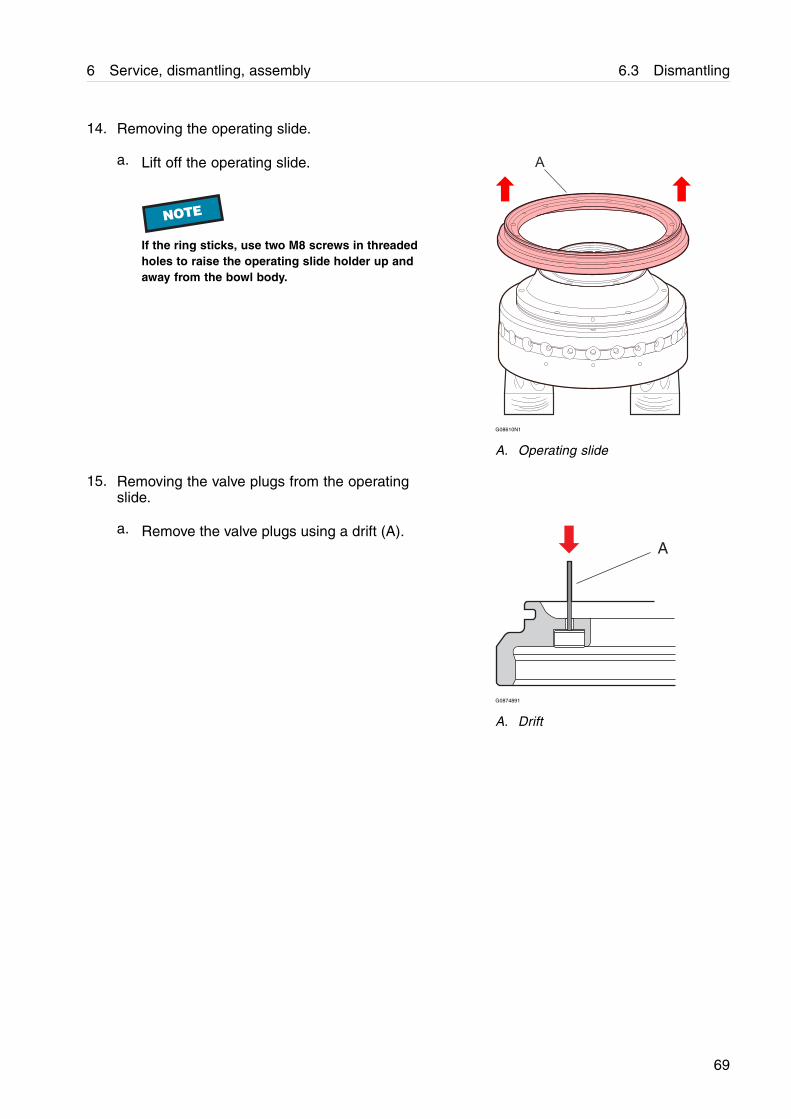
14. Removing the operating slide.
a. Lift off the operating slide.
NOTE
If the ring sticks, use two M8 screws in threadedholes to raise the operating slide holder up andaway from the bowl body.
A
G08610N1
A. Operating slide
15. Removing the valve plugs from the operatingslide.
a. Remove the valve plugs using a drift (A).A
G0874891
A. Drift
69
6.3 Dismantling 6 Service, dismantling, assembly
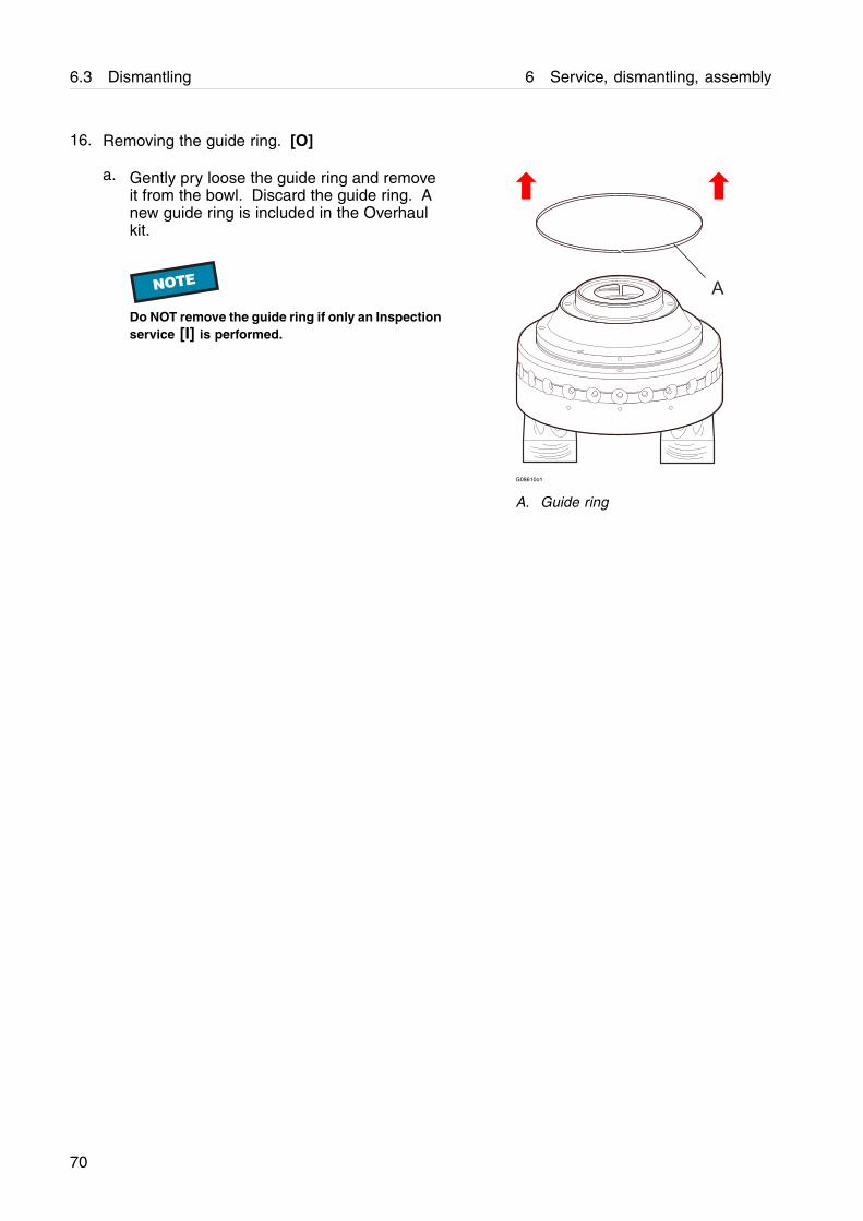
16. Removing the guide ring. [O]
a. Gently pry loose the guide ring and removeit from the bowl. Discard the guide ring. Anew guide ring is included in the Overhaulkit.
NOTE
Do NOT remove the guide ring if only an Inspectionservice [I] is performed.
G08610o1
A. Guide ring
70
6 Service, dismantling, assembly 6.3 Dismantling
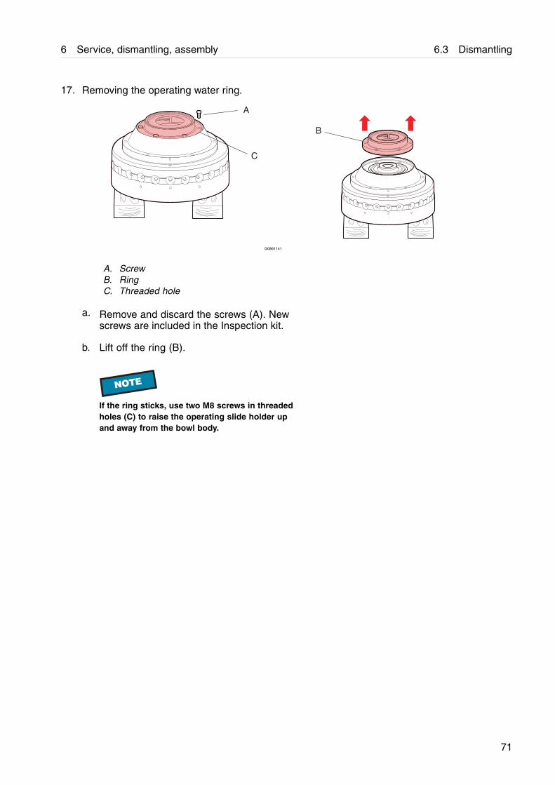
17. Removing the operating water ring.
B
A
C
G0861141
A. ScrewB. RingC. Threaded hole
a. Remove and discard the screws (A). Newscrews are included in the Inspection kit.
b. Lift off the ring (B).
NOTE
If the ring sticks, use two M8 screws in threadedholes (C) to raise the operating slide holder upand away from the bowl body.
71
6.3 Dismantling 6 Service, dismantling, assembly
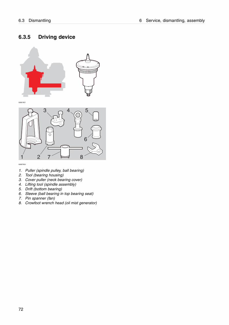
6.3.5 Driving device
G0857821
1 2
3 4 5
7
6
8G08579G1
1. Puller (spindle pulley, ball bearing)2. Tool (bearing housing)3. Cover puller (neck bearing cover)4. Lifting tool (spindle assembly)5. Drift (bottom bearing)6. Sleeve (ball bearing in top bearing seat)7. Pin spanner (fan)8. Crowfoot wrench head (oil mist generator)
72

6.3 Dismantling 6 Service, dismantling, assembly
6.3 Dismantling 6 Service, dismantling, assembly
1
2
3
9
10
11
12
13
14
15
16
17
18
19
20
22
21
23
25
26
27
29
30
31
33
34
35
36
37
38
39
45
6
7
8
24
28
32
40
42
41
G0859871
74
6 Service, dismantling, assembly 6.3 Dismantling
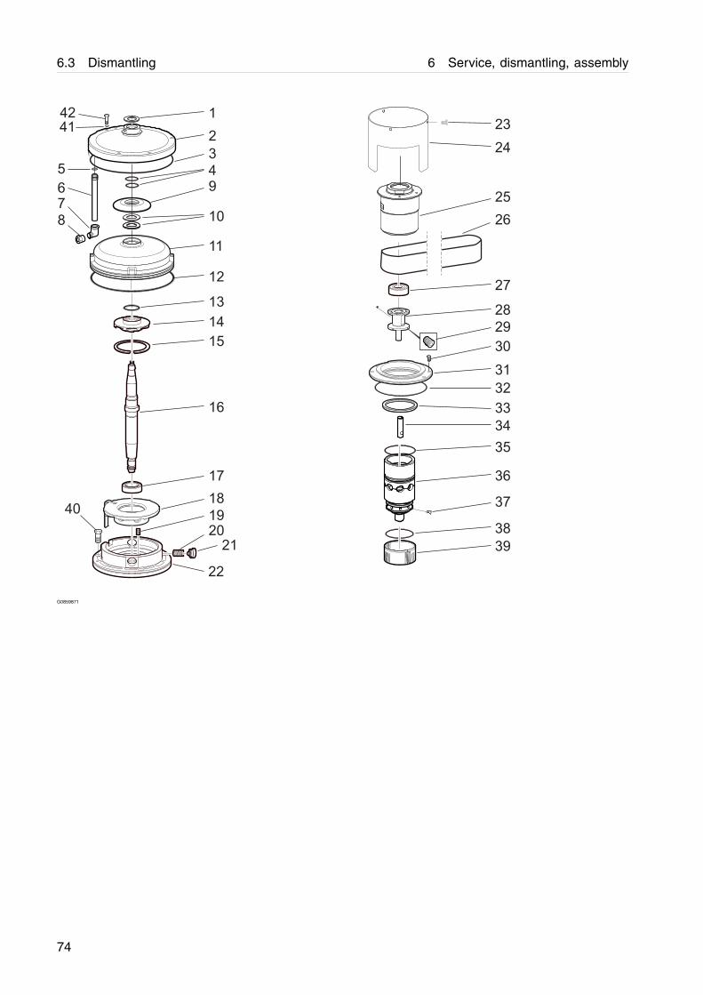
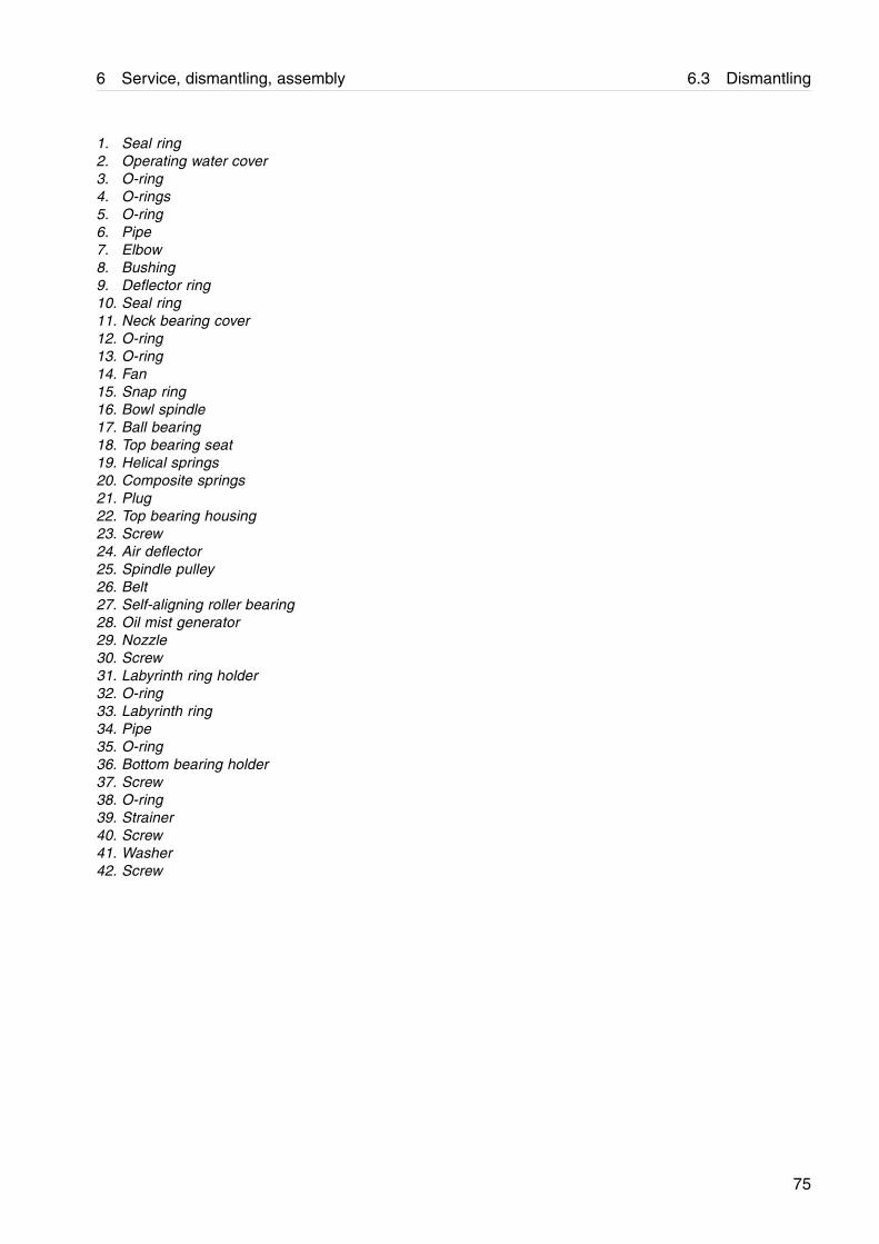
1. Seal ring2. Operating water cover3. O-ring4. O-rings5. O-ring6. Pipe7. Elbow8. Bushing9. Deflector ring10. Seal ring11. Neck bearing cover12. O-ring13. O-ring14. Fan15. Snap ring16. Bowl spindle17. Ball bearing18. Top bearing seat19. Helical springs20. Composite springs21. Plug22. Top bearing housing23. Screw24. Air deflector25. Spindle pulley26. Belt27. Self-aligning roller bearing28. Oil mist generator29. Nozzle30. Screw31. Labyrinth ring holder32. O-ring33. Labyrinth ring34. Pipe35. O-ring36. Bottom bearing holder37. Screw38. O-ring39. Strainer40. Screw41. Washer42. Screw
75
6.3 Dismantling 6 Service, dismantling, assembly
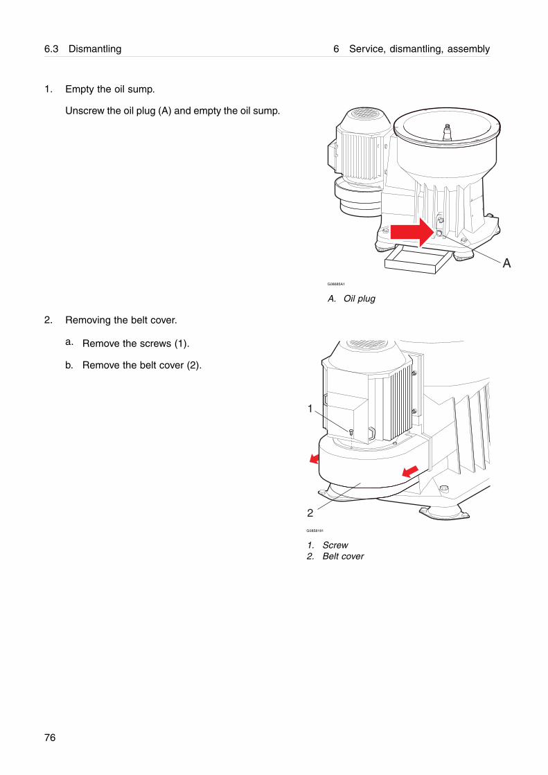
1. Empty the oil sump.
Unscrew the oil plug (A) and empty the oil sump.
AG08685A1
A. Oil plug
2. Removing the belt cover.
a. Remove the screws (1).
b. Remove the belt cover (2).
1
2G0858191
1. Screw2. Belt cover
76
6 Service, dismantling, assembly 6.3 Dismantling
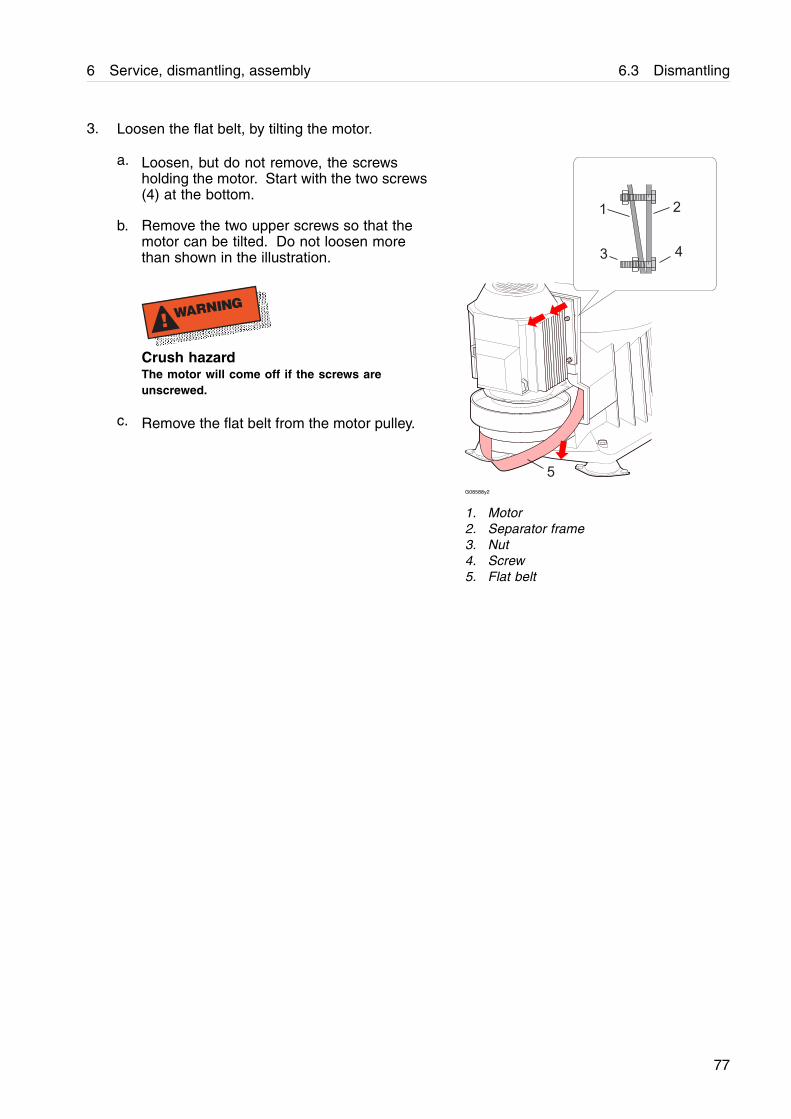
3. Loosen the flat belt, by tilting the motor.
a. Loosen, but do not remove, the screwsholding the motor. Start with the two screws(4) at the bottom.
b. Remove the two upper screws so that themotor can be tilted. Do not loosen morethan shown in the illustration.
! WARNING
Crush hazardThe motor will come off if the screws areunscrewed.
c. Remove the flat belt from the motor pulley.
1 2
3 4
5
G08588y2
1. Motor2. Separator frame3. Nut4. Screw5. Flat belt
77
6.3 Dismantling 6 Service, dismantling, assembly
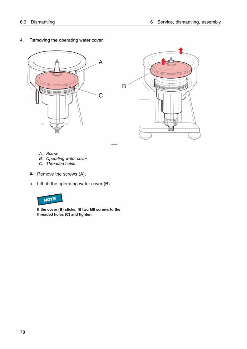
4. Removing the operating water cover.
A
B
C
G0858951
A. ScrewB. Operating water coverC. Threaded holes
a. Remove the screws (A).
b. Lift off the operating water cover (B).
NOTE
If the cover (B) sticks, fit two M8 screws to thethreaded holes (C) and tighten.
78
6 Service, dismantling, assembly 6.3 Dismantling
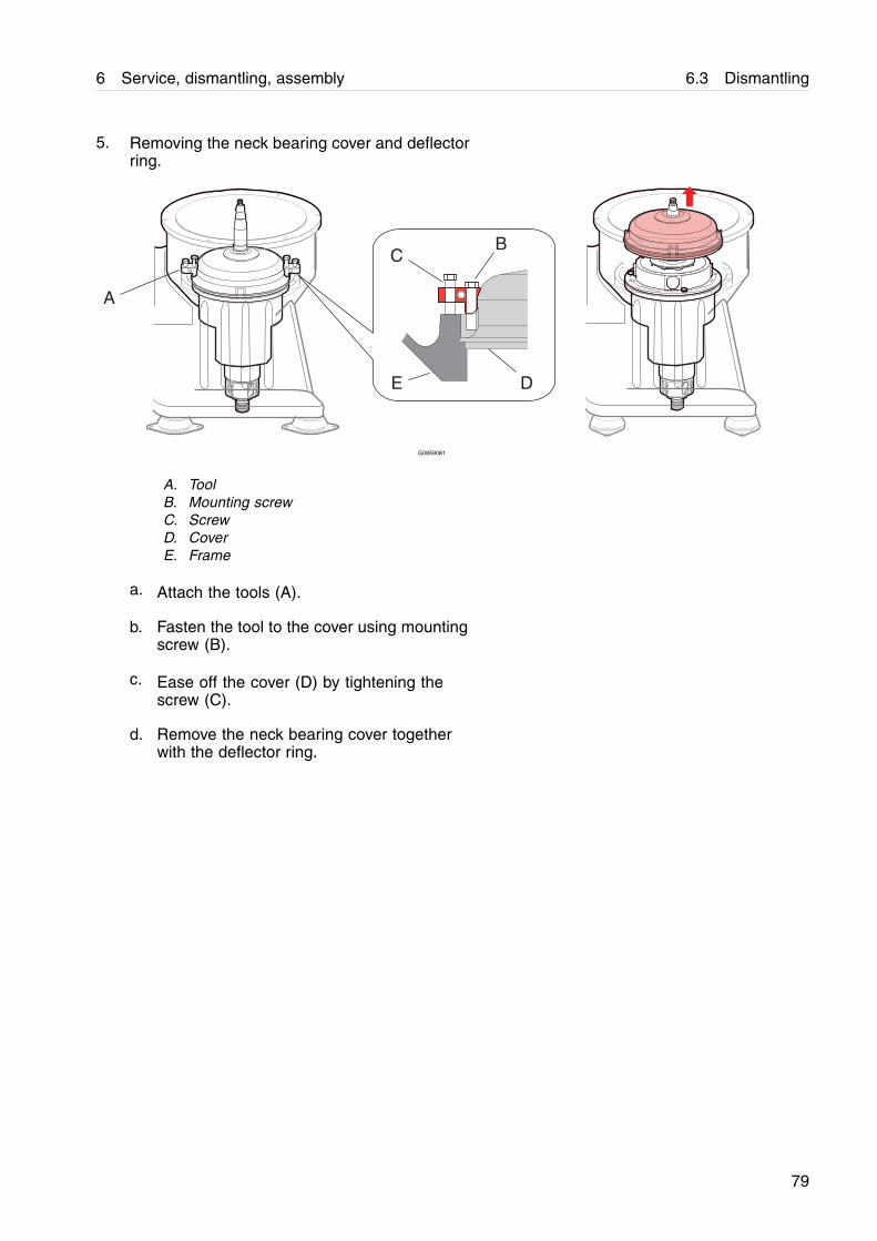
5. Removing the neck bearing cover and deflectorring.
A
BC
DE
G0859081
A. ToolB. Mounting screwC. ScrewD. CoverE. Frame
a. Attach the tools (A).
b. Fasten the tool to the cover using mountingscrew (B).
c. Ease off the cover (D) by tightening thescrew (C).
d. Remove the neck bearing cover togetherwith the deflector ring.
79
6.3 Dismantling 6 Service, dismantling, assembly
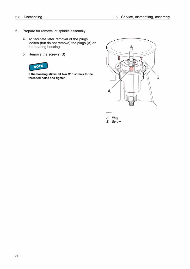
6. Prepare for removal of spindle assembly.
a. To facilitate later removal of the plugs,loosen (but do not remove) the plugs (A) onthe bearing housing.
b. Remove the screws (B)
NOTE
If the housing sticks, fit two M10 screws to thethreaded holes and tighten.
A
B
G0859181
A. PlugB. Screw
80
6 Service, dismantling, assembly 6.3 Dismantling
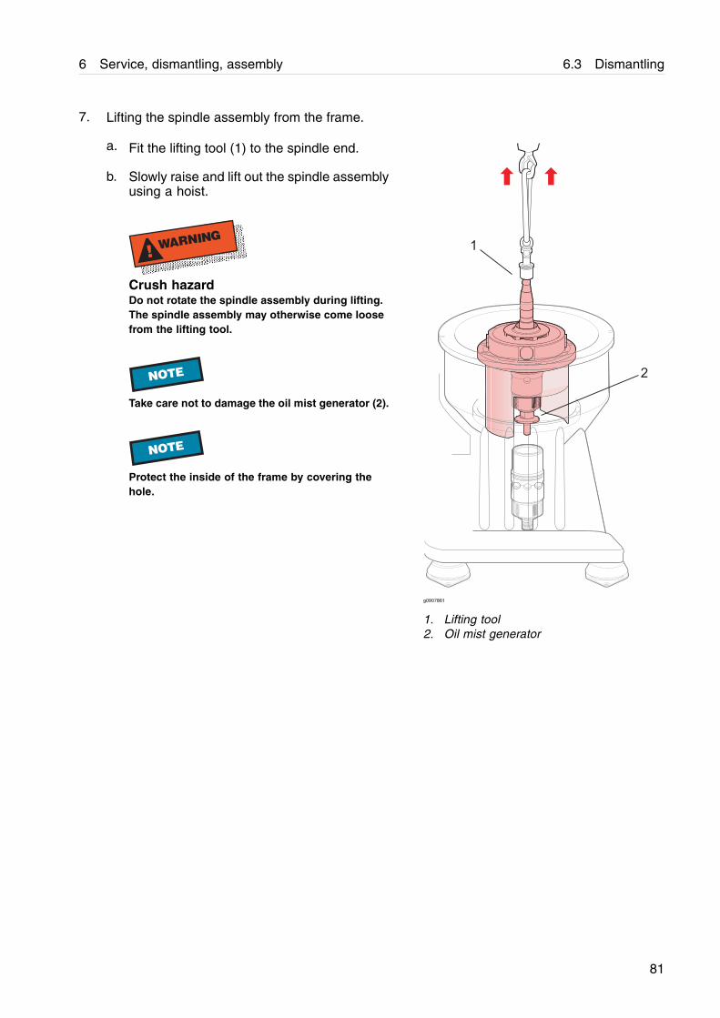
7. Lifting the spindle assembly from the frame.
a. Fit the lifting tool (1) to the spindle end.
b. Slowly raise and lift out the spindle assemblyusing a hoist.
! WARNING
Crush hazardDo not rotate the spindle assembly during lifting.The spindle assembly may otherwise come loosefrom the lifting tool.
NOTE
Take care not to damage the oil mist generator (2).
NOTE
Protect the inside of the frame by covering thehole.
g0907861
1. Lifting tool2. Oil mist generator
81
6.3 Dismantling 6 Service, dismantling, assembly
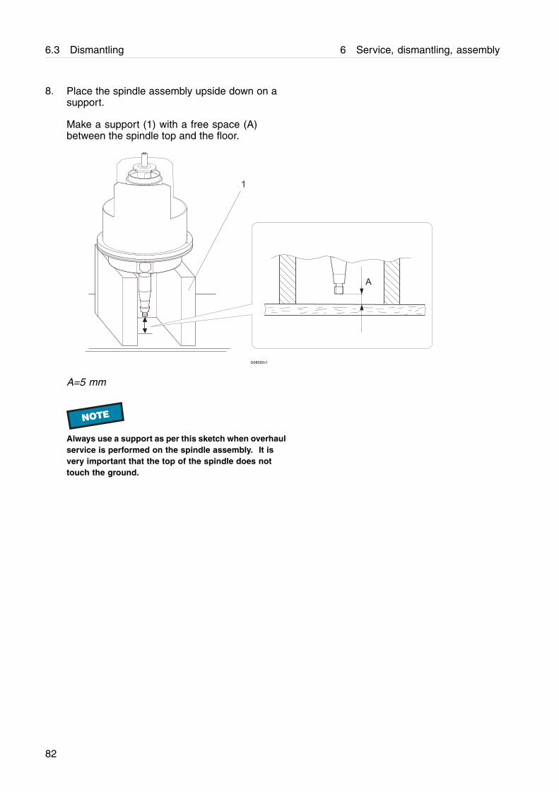
8. Place the spindle assembly upside down on asupport.
Make a support (1) with a free space (A)between the spindle top and the floor.
A
1
G08592c1
A=5 mm
NOTE
Always use a support as per this sketch when overhaulservice is performed on the spindle assembly. It isvery important that the top of the spindle does nottouch the ground.
82
6 Service, dismantling, assembly 6.3 Dismantling
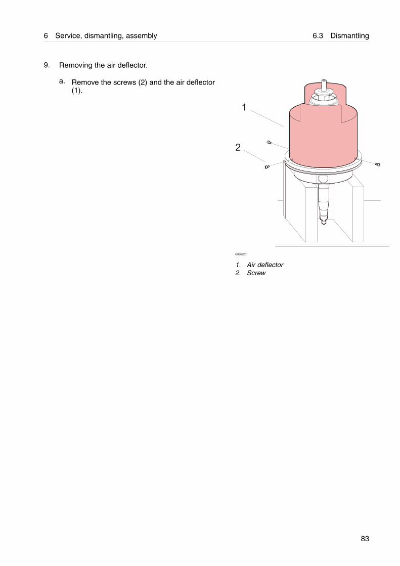
9. Removing the air deflector.
a. Remove the screws (2) and the air deflector(1).
G08592b1
1. Air deflector2. Screw
83
6.3 Dismantling 6 Service, dismantling, assembly
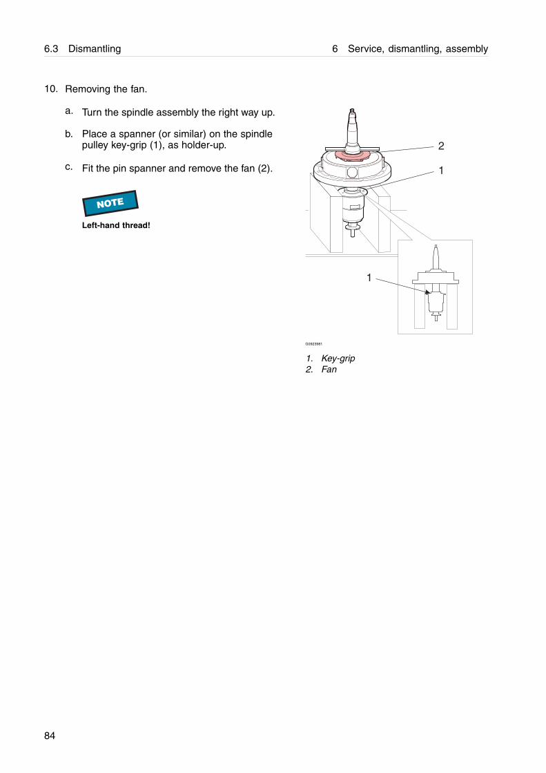
10. Removing the fan.
a. Turn the spindle assembly the right way up.
b. Place a spanner (or similar) on the spindlepulley key-grip (1), as holder-up.
c. Fit the pin spanner and remove the fan (2).
NOTE
Left-hand thread!
1
2
1
G0923981
1. Key-grip2. Fan
84
6 Service, dismantling, assembly 6.3 Dismantling
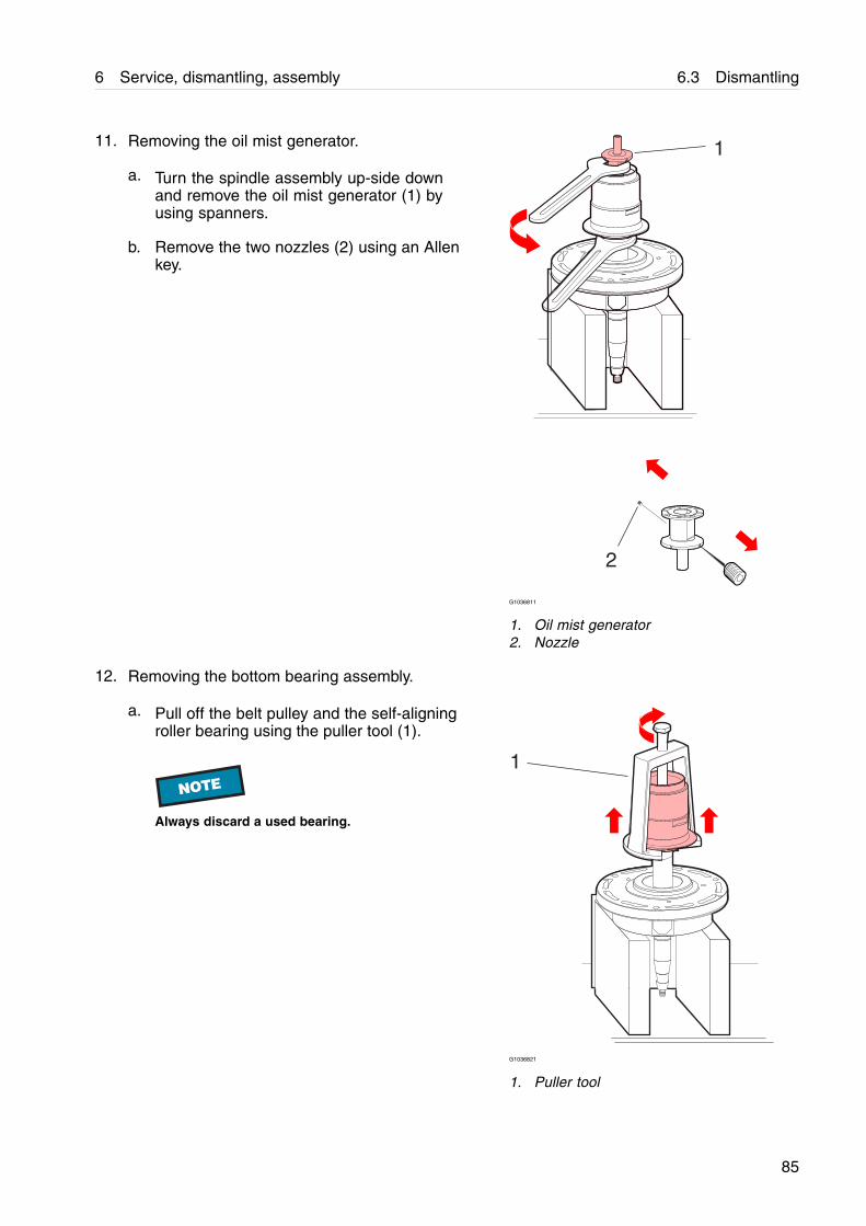
11. Removing the oil mist generator.
a. Turn the spindle assembly up-side downand remove the oil mist generator (1) byusing spanners.
b. Remove the two nozzles (2) using an Allenkey.
1
2
G1036811
1. Oil mist generator2. Nozzle
12. Removing the bottom bearing assembly.
a. Pull off the belt pulley and the self-aligningroller bearing using the puller tool (1).
NOTE
Always discard a used bearing.
1
G1036821
1. Puller tool
85
6.3 Dismantling 6 Service, dismantling, assembly
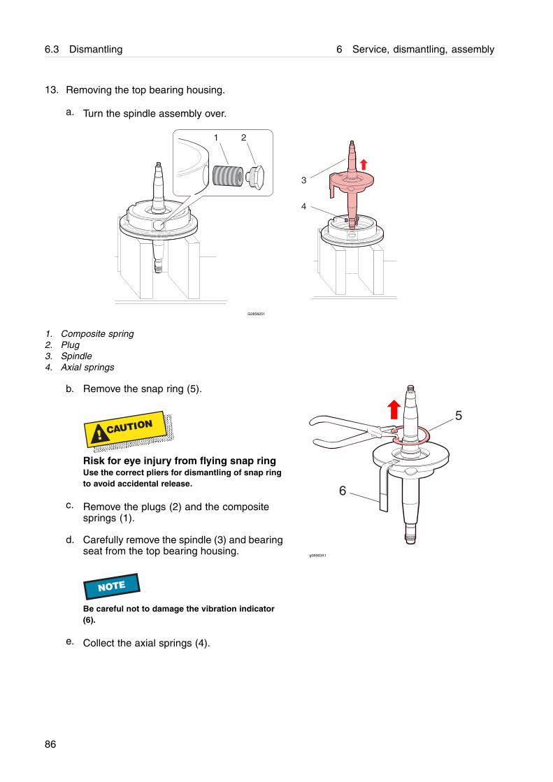
13. Removing the top bearing housing.
a. Turn the spindle assembly over.
3
1
4
2
G0858251
1. Composite spring2. Plug3. Spindle4. Axial springs
b. Remove the snap ring (5).
! CAUTION
Risk for eye injury from flying snap ringUse the correct pliers for dismantling of snap ringto avoid accidental release.
c. Remove the plugs (2) and the compositesprings (1).
d. Carefully remove the spindle (3) and bearingseat from the top bearing housing.
NOTE
Be careful not to damage the vibration indicator(6).
e. Collect the axial springs (4).
5
6
g08583A1
86
6 Service, dismantling, assembly 6.3 Dismantling
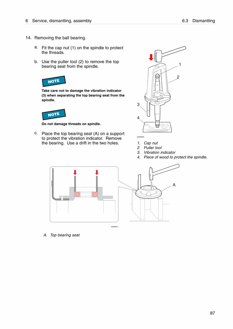
14. Removing the ball bearing.
a. Fit the cap nut (1) on the spindle to protectthe threads.
b. Use the puller tool (2) to remove the topbearing seat from the spindle.
NOTE
Take care not to damage the vibration indicator(3) when separating the top bearing seat from thespindle.
NOTE
Do not damage threads on spindle.
c. Place the top bearing seat (A) on a supportto protect the vibration indicator. Removethe bearing. Use a drift in the two holes.
1
2
3
4
G0858381
1. Cap nut2. Puller tool3. Vibration indicator4. Piece of wood to protect the spindle.
A
G0858371
A. Top bearing seat
87
6.3 Dismantling 6 Service, dismantling, assembly
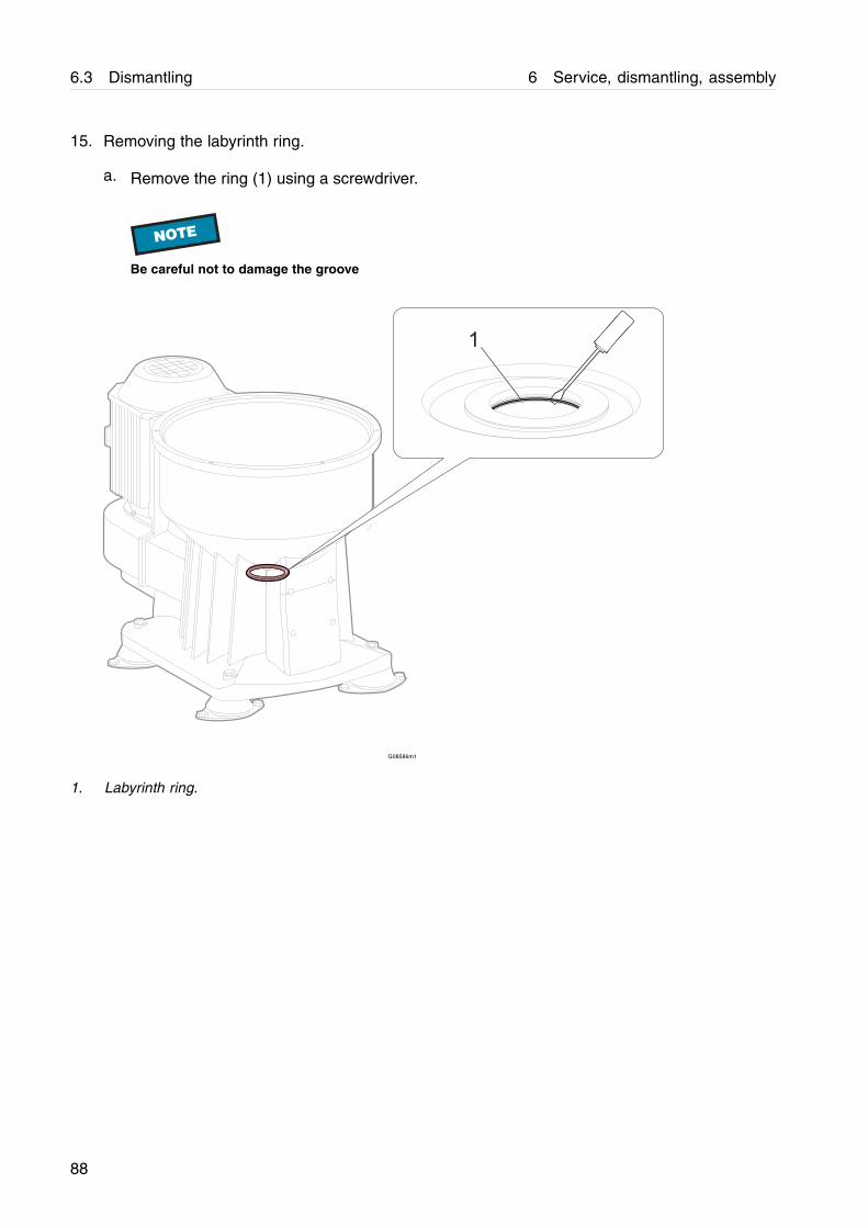
15. Removing the labyrinth ring.
a. Remove the ring (1) using a screwdriver.
NOTE
Be careful not to damage the groove
G08586m1
1. Labyrinth ring.
88

6 Service, dismantling, assembly 6.3 Dismantling
16. Removing the bottom bearing holder.
a. Fit the tool (4) into the bottom bearing holderand attach the socket (3), extension rod (2)and T-handle (1). 1
2
3
4
G08586J1
1. T-handle2. Extension rod3. Socket4. Tool
b. Loosen the bottom bearing holder (A) byturning it counter clockwise. Remove it byhand.
G08586k1
A. Bottom bearing holder
89
6.3 Dismantling 6 Service, dismantling, assembly
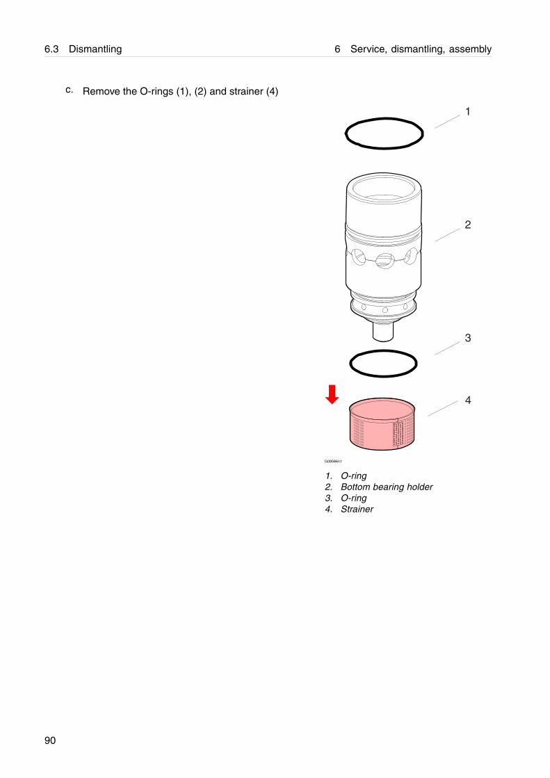
c. Remove the O-rings (1), (2) and strainer (4)
1
4
2
3
G08586n1
1. O-ring2. Bottom bearing holder3. O-ring4. Strainer
90
6 Service, dismantling, assembly 6.3 Dismantling
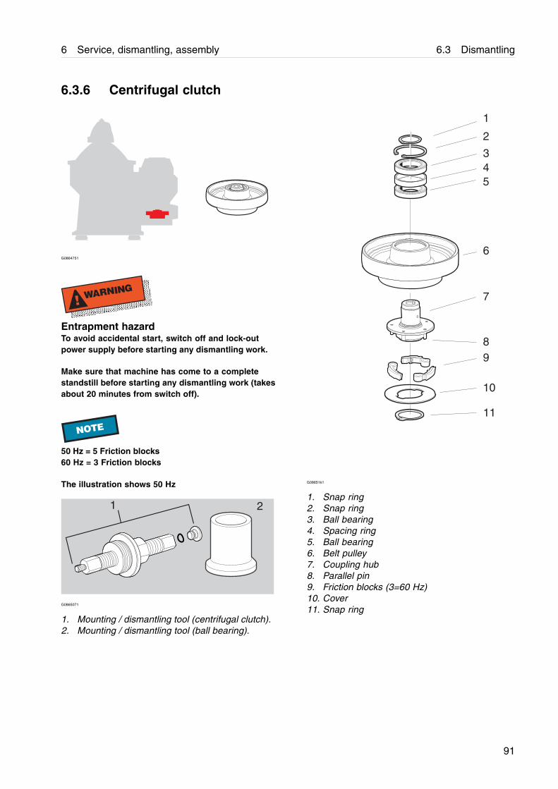
6.3.6 Centrifugal clutch
G0864751
! WARNING
Entrapment hazardTo avoid accidental start, switch off and lock-outpower supply before starting any dismantling work.
Make sure that machine has come to a completestandstill before starting any dismantling work (takesabout 20 minutes from switch off).
NOTE
50 Hz = 5 Friction blocks60 Hz = 3 Friction blocks
The illustration shows 50 Hz
1 2
G0865071
1. Mounting / dismantling tool (centrifugal clutch).2. Mounting / dismantling tool (ball bearing).
G08651k1
1. Snap ring2. Snap ring3. Ball bearing4. Spacing ring5. Ball bearing6. Belt pulley7. Coupling hub8. Parallel pin9. Friction blocks (3=60 Hz)10. Cover11. Snap ring
91
6.3 Dismantling 6 Service, dismantling, assembly
NOTE
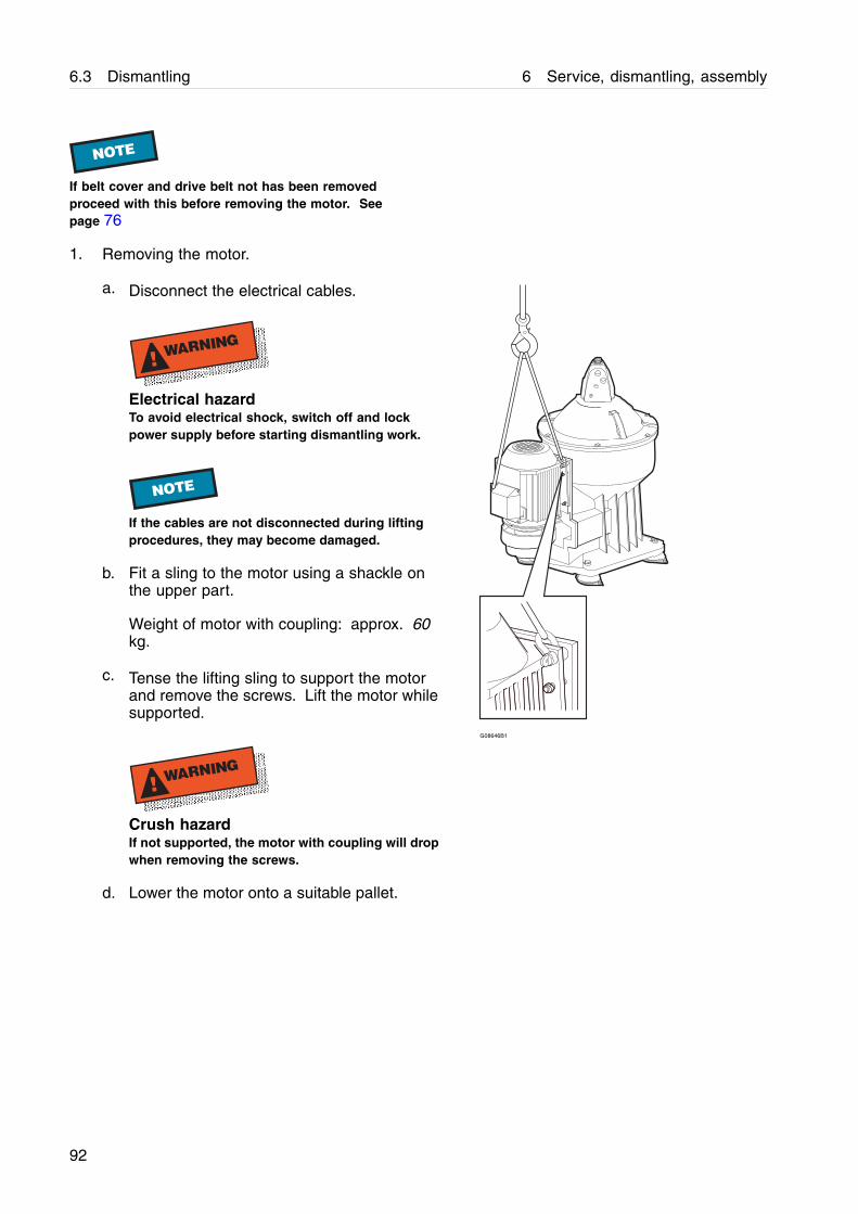
If belt cover and drive belt not has been removedproceed with this before removing the motor. Seepage 76
1. Removing the motor.
a. Disconnect the electrical cables.
! WARNING
Electrical hazardTo avoid electrical shock, switch off and lockpower supply before starting dismantling work.
NOTE
If the cables are not disconnected during liftingprocedures, they may become damaged.
b. Fit a sling to the motor using a shackle onthe upper part.
Weight of motor with coupling: approx. 60kg.
c. Tense the lifting sling to support the motorand remove the screws. Lift the motor whilesupported.
! WARNING
Crush hazardIf not supported, the motor with coupling will dropwhen removing the screws.
G08646B1
d. Lower the motor onto a suitable pallet.
92
6 Service, dismantling, assembly 6.3 Dismantling
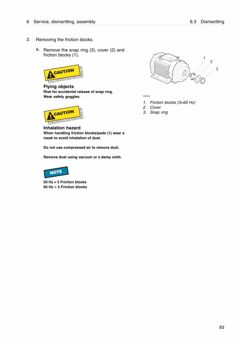
2. Removing the friction blocks.
a. Remove the snap ring (3), cover (2) andfriction blocks (1).
! CAUTION
Flying objectsRisk for accidental release of snap ring.Wear safety goggles.
! CAUTION
Inhalation hazardWhen handling friction blocks/pads (1) wear amask to avoid inhalation of dust.
Do not use compressed air to remove dust.
Remove dust using vacuum or a damp cloth.
NOTE
50 Hz = 5 Friction blocks60 Hz = 3 Friction blocks
G08652g1
1. Friction blocks (3=60 Hz)2. Cover3. Snap ring
93
6.3 Dismantling 6 Service, dismantling, assembly
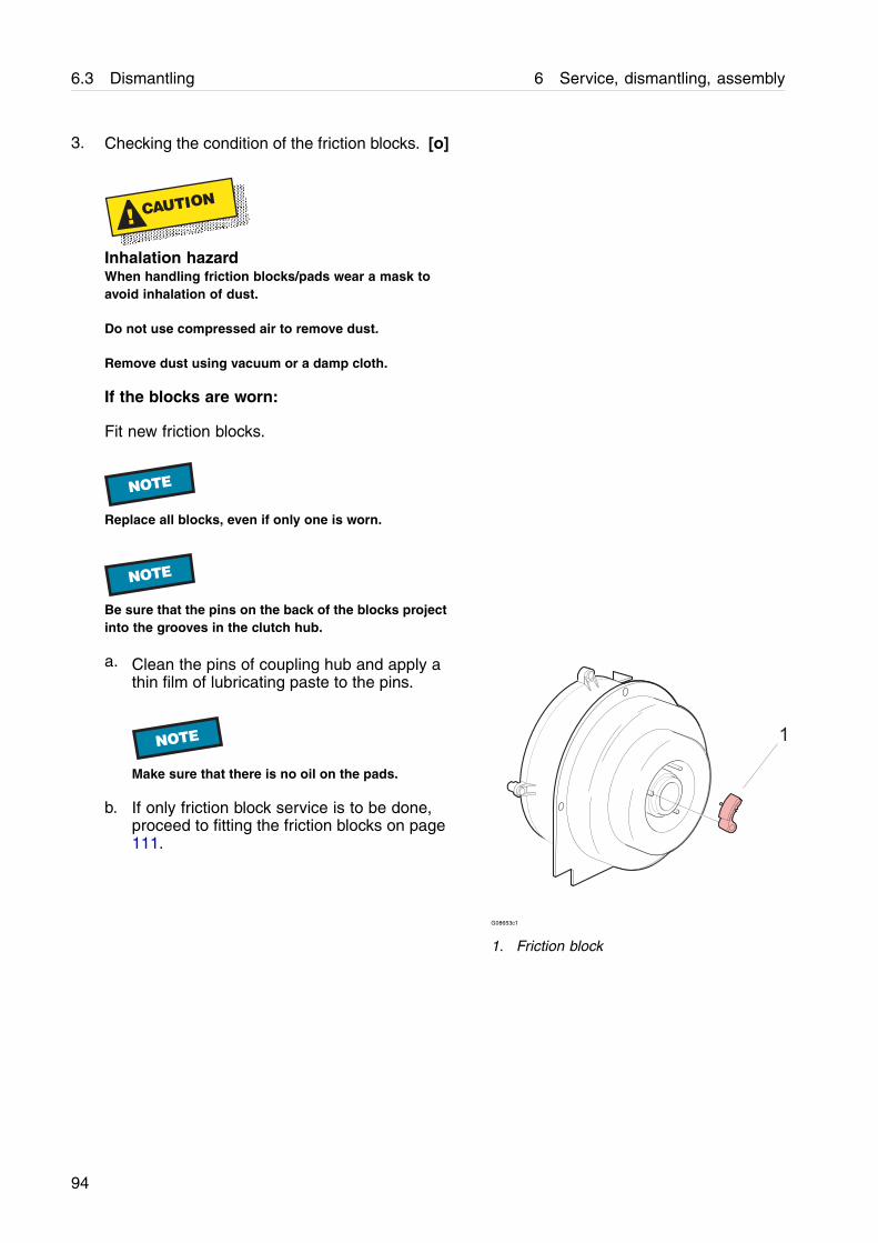
3. Checking the condition of the friction blocks. [o]
! CAUTION
Inhalation hazardWhen handling friction blocks/pads wear a mask toavoid inhalation of dust.
Do not use compressed air to remove dust.
Remove dust using vacuum or a damp cloth.
If the blocks are worn:
Fit new friction blocks.
NOTE
Replace all blocks, even if only one is worn.
NOTE
Be sure that the pins on the back of the blocks projectinto the grooves in the clutch hub.
a. Clean the pins of coupling hub and apply athin film of lubricating paste to the pins.
NOTE
Make sure that there is no oil on the pads.
b. If only friction block service is to be done,proceed to fitting the friction blocks on page111.
G08653c1
1. Friction block
94
6 Service, dismantling, assembly 6.3 Dismantling
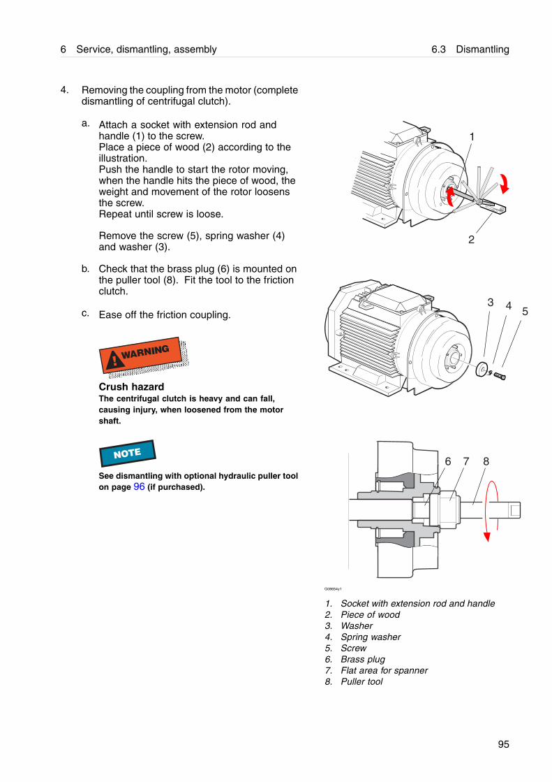
4. Removing the coupling from the motor (completedismantling of centrifugal clutch).
a. Attach a socket with extension rod andhandle (1) to the screw.Place a piece of wood (2) according to theillustration.Push the handle to start the rotor moving,when the handle hits the piece of wood, theweight and movement of the rotor loosensthe screw.Repeat until screw is loose.
Remove the screw (5), spring washer (4)and washer (3).
b. Check that the brass plug (6) is mounted onthe puller tool (8). Fit the tool to the frictionclutch.
c. Ease off the friction coupling.
! WARNING
Crush hazardThe centrifugal clutch is heavy and can fall,causing injury, when loosened from the motorshaft.
NOTE
See dismantling with optional hydraulic puller toolon page 96 (if purchased).
435
1
6 7 8
2
G08654y1
1. Socket with extension rod and handle2. Piece of wood3. Washer4. Spring washer5. Screw6. Brass plug7. Flat area for spanner8. Puller tool
95
6.3 Dismantling 6 Service, dismantling, assembly
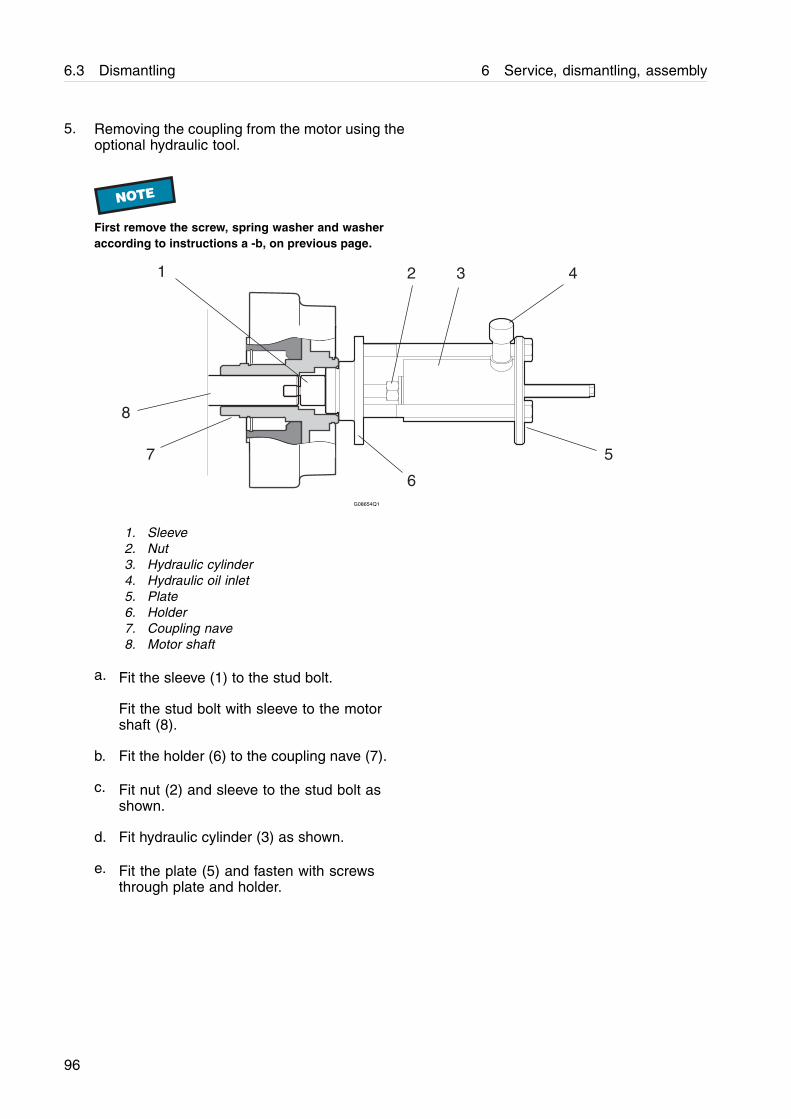
5. Removing the coupling from the motor using theoptional hydraulic tool.
NOTE
First remove the screw, spring washer and washeraccording to instructions a -b, on previous page.
1 2
5
3 4
6
7
8
G08654Q1
1. Sleeve2. Nut3. Hydraulic cylinder4. Hydraulic oil inlet5. Plate6. Holder7. Coupling nave8. Motor shaft
a. Fit the sleeve (1) to the stud bolt.
Fit the stud bolt with sleeve to the motorshaft (8).
b. Fit the holder (6) to the coupling nave (7).
c. Fit nut (2) and sleeve to the stud bolt asshown.
d. Fit hydraulic cylinder (3) as shown.
e. Fit the plate (5) and fasten with screwsthrough plate and holder.
96
6 Service, dismantling, assembly 6.3 Dismantling
f. Attach the hose from the hand pump to thehydraulic oil inlet (4).
Ease off the friction coupling by pumping thehandle on the pump until stop.
Release pressure on the hand pump andadjust the nut on the stud bolt.
Repeat until coupling is loose.
! WARNING
Crush hazardThe centrifugal clutch is heavy and can fall,causing injury, when loosened from the motorshaft.
97
6.3 Dismantling 6 Service, dismantling, assembly
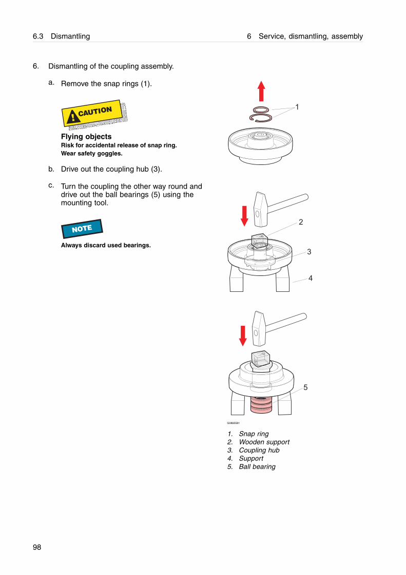
6. Dismantling of the coupling assembly.
a. Remove the snap rings (1).
! CAUTION
Flying objectsRisk for accidental release of snap ring.Wear safety goggles.
b. Drive out the coupling hub (3).
c. Turn the coupling the other way round anddrive out the ball bearings (5) using themounting tool.
NOTE
Always discard used bearings.
G0865581
1. Snap ring2. Wooden support3. Coupling hub4. Support5. Ball bearing
98
6 Service, dismantling, assembly 6.4 Actions before assembly
6.4 Actions before assembly
6.4.1 Cleaning
[i], [o]
Clean the separator parts according to thediagram below. Afterwards, protect all cleanedcarbon steel parts against corrosion by oiling.
! WARNING
Electrical hazardNever wash down a separator with a direct waterstream. Never play a water jet on the motor. Totallyenclosed motors can be damaged by direct hosingto the same extent as open motors, resulting inshort-circuit and internal corrosion.
! CAUTION
Cut hazardSharp edges on the separator discs may cause cuts.
99
6.4 Actions before assembly 6 Service, dismantling, assembly
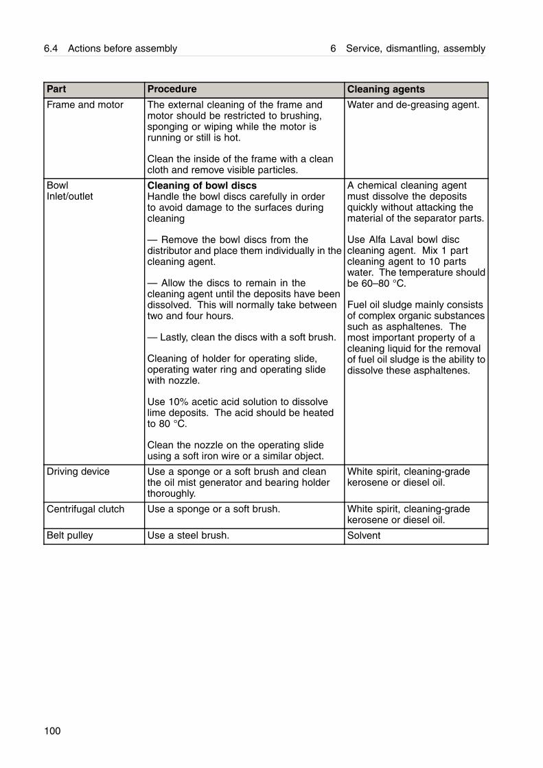
Part Procedure Cleaning agents
Frame and motor The external cleaning of the frame andmotor should be restricted to brushing,sponging or wiping while the motor isrunning or still is hot.
Clean the inside of the frame with a cleancloth and remove visible particles.
Water and de-greasing agent.
BowlInlet/outlet
Cleaning of bowl discsHandle the bowl discs carefully in orderto avoid damage to the surfaces duringcleaning
— Remove the bowl discs from thedistributor and place them individually in thecleaning agent.
— Allow the discs to remain in thecleaning agent until the deposits have beendissolved. This will normally take betweentwo and four hours.
— Lastly, clean the discs with a soft brush.
Cleaning of holder for operating slide,operating water ring and operating slidewith nozzle.
Use 10% acetic acid solution to dissolvelime deposits. The acid should be heatedto 80 °C.
Clean the nozzle on the operating slideusing a soft iron wire or a similar object.
A chemical cleaning agentmust dissolve the depositsquickly without attacking thematerial of the separator parts.
Use Alfa Laval bowl disccleaning agent. Mix 1 partcleaning agent to 10 partswater. The temperature shouldbe 60–80 °C.
Fuel oil sludge mainly consistsof complex organic substancessuch as asphaltenes. Themost important property of acleaning liquid for the removalof fuel oil sludge is the ability todissolve these asphaltenes.
Driving device Use a sponge or a soft brush and cleanthe oil mist generator and bearing holderthoroughly.
White spirit, cleaning-gradekerosene or diesel oil.
Centrifugal clutch Use a sponge or a soft brush. White spirit, cleaning-gradekerosene or diesel oil.
Belt pulley Use a steel brush. Solvent
100
6 Service, dismantling, assembly 6.4 Actions before assembly
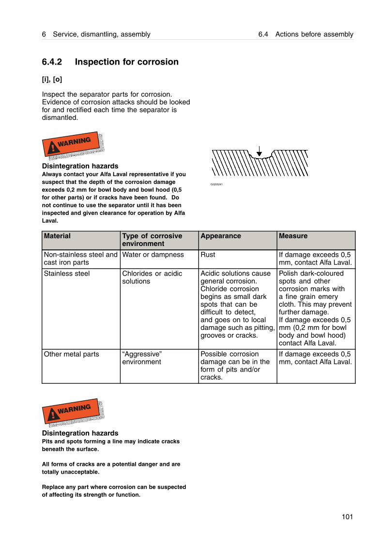
6.4.2 Inspection for corrosion
[i], [o]
Inspect the separator parts for corrosion.Evidence of corrosion attacks should be lookedfor and rectified each time the separator isdismantled.
! WARNING
Disintegration hazardsAlways contact your Alfa Laval representative if yoususpect that the depth of the corrosion damageexceeds 0,2 mm for bowl body and bowl hood (0,5for other parts) or if cracks have been found. Donot continue to use the separator until it has beeninspected and given clearance for operation by AlfaLaval.
G0205241
Material Type of corrosiveenvironment
Appearance Measure
Non-stainless steel andcast iron parts
Water or dampness Rust If damage exceeds 0,5mm, contact Alfa Laval.
Stainless steel Chlorides or acidicsolutions
Acidic solutions causegeneral corrosion.Chloride corrosionbegins as small darkspots that can bedifficult to detect,and goes on to localdamage such as pitting,grooves or cracks.
Polish dark-colouredspots and othercorrosion marks witha fine grain emerycloth. This may preventfurther damage.If damage exceeds 0,5mm (0,2 mm for bowlbody and bowl hood)contact Alfa Laval.
Other metal parts “Aggressive”environment
Possible corrosiondamage can be in theform of pits and/orcracks.
If damage exceeds 0,5mm, contact Alfa Laval.
! WARNING
Disintegration hazardsPits and spots forming a line may indicate cracksbeneath the surface.
All forms of cracks are a potential danger and aretotally unacceptable.
Replace any part where corrosion can be suspectedof affecting its strength or function.
101
6.4 Actions before assembly 6 Service, dismantling, assembly
6.4.3 Inspection for cracks
[i], [o]
Check the separator parts for cracks. It isparticularly important to inspect for cracks inrotating parts, and especially the pillars betweenthe sludge ports in the bowl wall.
! WARNING
Disintegration hazardAll forms of cracks are potentially dangerous asthey reduce the strength and functional ability ofcomponents.
Always replace a part if cracks are present.
Cracks can occur from cyclic material stressesand corrosion. Keeping the separator and itsparts clean and free from deposits will help toprevent corrosion attacks.
! WARNING
Disintegration hazardsAlways contact your Alfa Laval representative if yoususpect that the depth of the damage exceeds 0,2 mmfor bowl body and bowl hood (0,5 for other parts).
Do not continue to use the separator until it has beeninspected and given clearance for operation by AlfaLaval.
102
6 Service, dismantling, assembly 6.4 Actions before assembly
6.4.4 Inspection for erosion
[i], [o]
Erosion may occur when particles suspended inthe process liquid slide along or strike againsta surface.
Erosion is characterised by:
a. Burnished traces in the material.
b. Dents and pits having a granular and shiny surface.
1. Inspect the bowl and inlet/outlet parts for erosiondamages.
NOTE
Always contact your Alfa Laval representative if yoususpect that the depth of the damage exceeds 0,2 mmfor bowl body and bowl hood (0,5 for other parts). Donot continue to use the separator until it has beeninspected and cleared for operation by Alfa Laval.
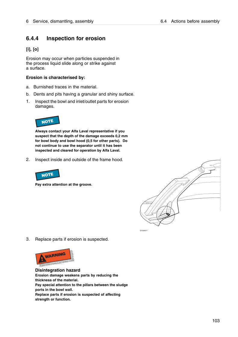
2. Inspect inside and outside of the frame hood.
NOTE
Pay extra attention at the groove.
G1034011
3. Replace parts if erosion is suspected.
! WARNING
Disintegration hazardErosion damage weakens parts by reducing thethickness of the material.Pay special attention to the pillars between the sludgeports in the bowl wall.Replace parts if erosion is suspected of affectingstrength or function.
103
6.4 Actions before assembly 6 Service, dismantling, assembly
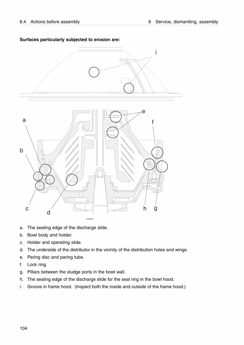
Surfaces particularly subjected to erosion are:
b
a
dc
e
f
gh
i
G1033631
a. The sealing edge of the discharge slide.
b. Bowl body and holder.
c. Holder and operating slide.
d. The underside of the distributor in the vicinity of the distribution holes and wings.
e. Paring disc and paring tube.
f. Lock ring.
g. Pillars between the sludge ports in the bowl wall.
h. The sealing edge of the discharge slide for the seal ring in the bowl hood.
i. Groove in frame hood. (Inspect both the inside and outside of the frame hood.)
104
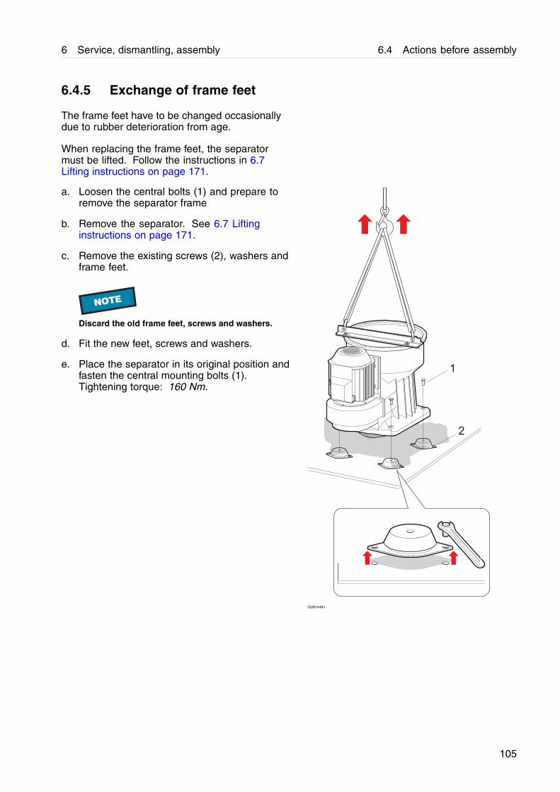
6 Service, dismantling, assembly 6.4 Actions before assembly
6.4.5 Exchange of frame feet
The frame feet have to be changed occasionallydue to rubber deterioration from age.
When replacing the frame feet, the separatormust be lifted. Follow the instructions in 6.7Lifting instructions on page 171.
a. Loosen the central bolts (1) and prepare toremove the separator frame
b. Remove the separator. See 6.7 Liftinginstructions on page 171.
c. Remove the existing screws (2), washers andframe feet.
NOTE
Discard the old frame feet, screws and washers.
d. Fit the new feet, screws and washers.
e. Place the separator in its original position andfasten the central mounting bolts (1).Tightening torque: 160 Nm.
1
2
G0874481
105

6.4 Actions before assembly 6 Service, dismantling, assembly
6.4.6 Lubrication of bowl parts
Apply a thin layer of Molykote, or equivalentlubrication, on all the contact surfaces shownin the illustration.
G09117j1
A. Molykote 10001. Bowl hood2. Bowl body3. Discharge slide4. Operating slide5. Holder6. Operating water ring7. Screw8. Nut
106

6 Service, dismantling, assembly 6.5 Assembly
6.5 Assembly
! WARNING
Entrapment hazardTo avoid accidental start, switch off and lock powersupply before starting any assembly work.
107
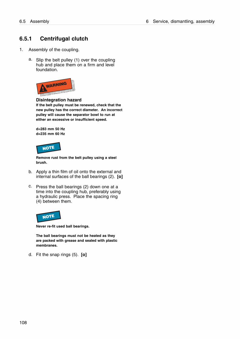
6.5 Assembly 6 Service, dismantling, assembly
6.5.1 Centrifugal clutch
1. Assembly of the coupling.
a. Slip the belt pulley (1) over the couplinghub and place them on a firm and levelfoundation.
! WARNING
Disintegration hazardIf the belt pulley must be renewed, check that thenew pulley has the correct diameter. An incorrectpulley will cause the separator bowl to run ateither an excessive or insufficient speed.
d=283 mm 50 Hzd=235 mm 60 Hz
NOTE
Remove rust from the belt pulley using a steelbrush.
b. Apply a thin film of oil onto the external andinternal surfaces of the ball bearings (2). [o]
c. Press the ball bearings (2) down one at atime into the coupling hub, preferably usinga hydraulic press. Place the spacing ring(4) between them.
NOTE
Never re-fit used ball bearings.
The ball bearings must not be heated as theyare packed with grease and sealed with plasticmembranes.
d. Fit the snap rings (5). [o]
108
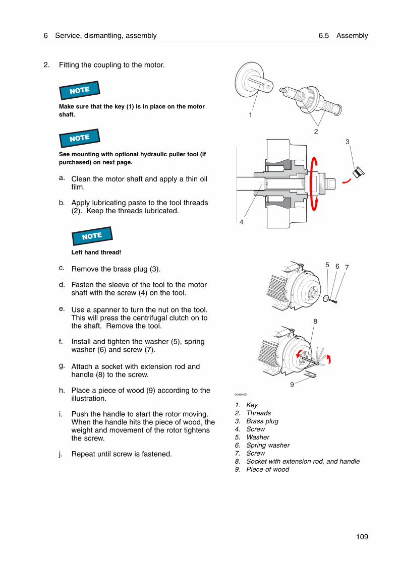
6 Service, dismantling, assembly 6.5 Assembly
2. Fitting the coupling to the motor.
NOTE
Make sure that the key (1) is in place on the motorshaft.
NOTE
See mounting with optional hydraulic puller tool (ifpurchased) on next page.
a. Clean the motor shaft and apply a thin oilfilm.
b. Apply lubricating paste to the tool threads(2). Keep the threads lubricated.
NOTE
Left hand thread!
c. Remove the brass plug (3).
d. Fasten the sleeve of the tool to the motorshaft with the screw (4) on the tool.
e. Use a spanner to turn the nut on the tool.This will press the centrifugal clutch on tothe shaft. Remove the tool.
f. Install and tighten the washer (5), springwasher (6) and screw (7).
g. Attach a socket with extension rod andhandle (8) to the screw.
h. Place a piece of wood (9) according to theillustration.
i. Push the handle to start the rotor moving.When the handle hits the piece of wood, theweight and movement of the rotor tightensthe screw.
j. Repeat until screw is fastened.
1
2
3
4
5 6 7
8
9G08654Z1
1. Key2. Threads3. Brass plug4. Screw5. Washer6. Spring washer7. Screw8. Socket with extension rod, and handle9. Piece of wood
109
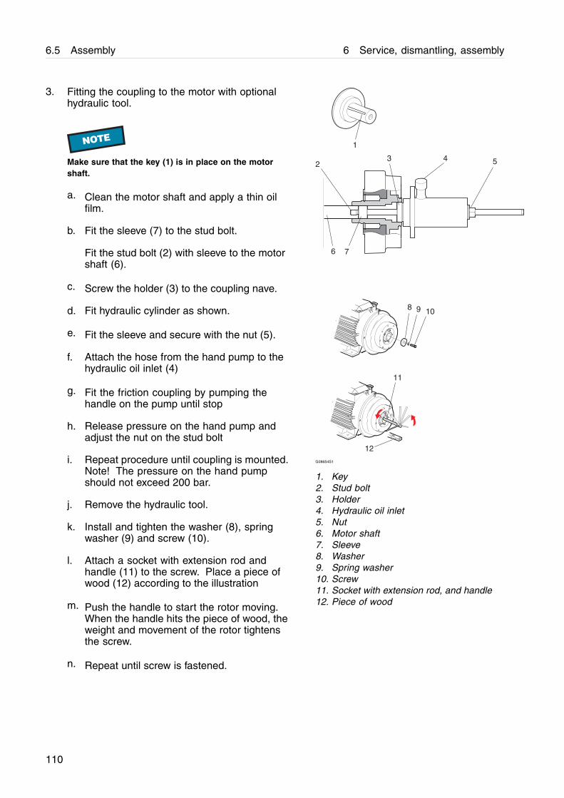
6.5 Assembly 6 Service, dismantling, assembly
3. Fitting the coupling to the motor with optionalhydraulic tool.
NOTE
Make sure that the key (1) is in place on the motorshaft.
a. Clean the motor shaft and apply a thin oilfilm.
b. Fit the sleeve (7) to the stud bolt.
Fit the stud bolt (2) with sleeve to the motorshaft (6).
c. Screw the holder (3) to the coupling nave.
d. Fit hydraulic cylinder as shown.
e. Fit the sleeve and secure with the nut (5).
f. Attach the hose from the hand pump to thehydraulic oil inlet (4)
g. Fit the friction coupling by pumping thehandle on the pump until stop
h. Release pressure on the hand pump andadjust the nut on the stud bolt
i. Repeat procedure until coupling is mounted.Note! The pressure on the hand pumpshould not exceed 200 bar.
j. Remove the hydraulic tool.
k. Install and tighten the washer (8), springwasher (9) and screw (10).
l. Attach a socket with extension rod andhandle (11) to the screw. Place a piece ofwood (12) according to the illustration
m. Push the handle to start the rotor moving.When the handle hits the piece of wood, theweight and movement of the rotor tightensthe screw.
n. Repeat until screw is fastened.
12
1
23 4 5
76
8 9 10
11
G08654S1
1. Key2. Stud bolt3. Holder4. Hydraulic oil inlet5. Nut6. Motor shaft7. Sleeve8. Washer9. Spring washer10. Screw11. Socket with extension rod, and handle12. Piece of wood
110
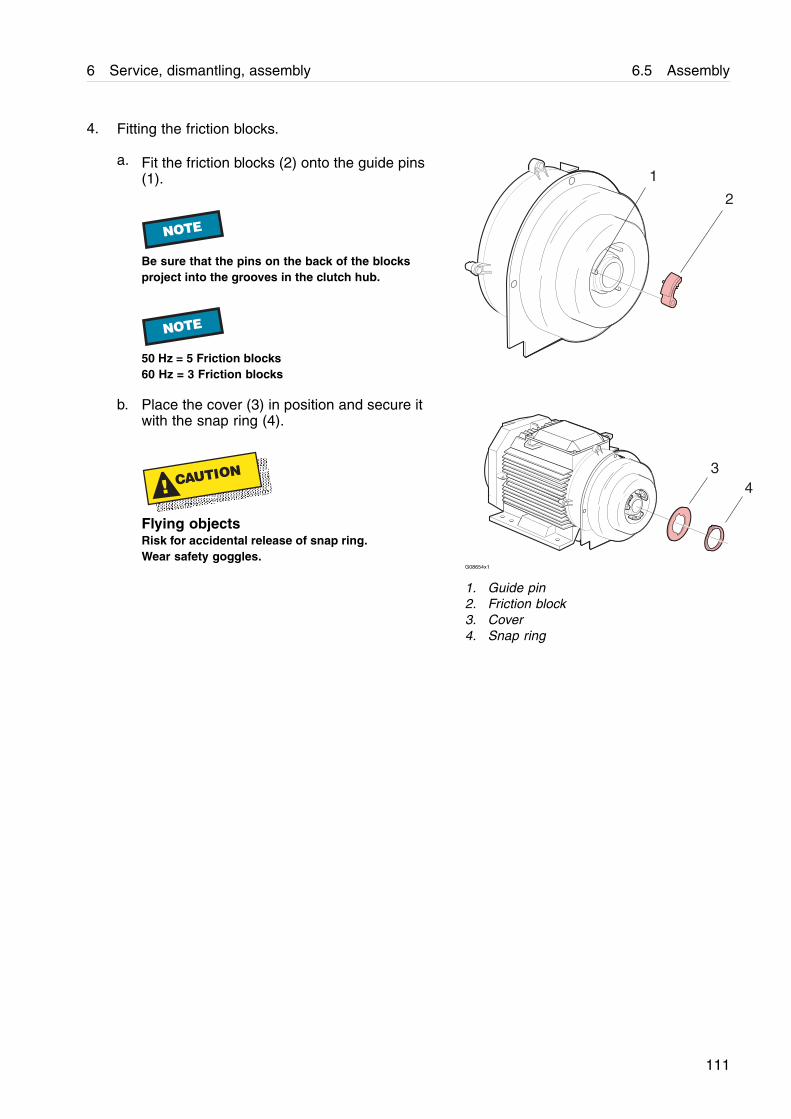
6 Service, dismantling, assembly 6.5 Assembly
4. Fitting the friction blocks.
a. Fit the friction blocks (2) onto the guide pins(1).
NOTE
Be sure that the pins on the back of the blocksproject into the grooves in the clutch hub.
NOTE
50 Hz = 5 Friction blocks60 Hz = 3 Friction blocks
b. Place the cover (3) in position and secure itwith the snap ring (4).
! CAUTION
Flying objectsRisk for accidental release of snap ring.Wear safety goggles.
G08654x1
1. Guide pin2. Friction block3. Cover4. Snap ring
111
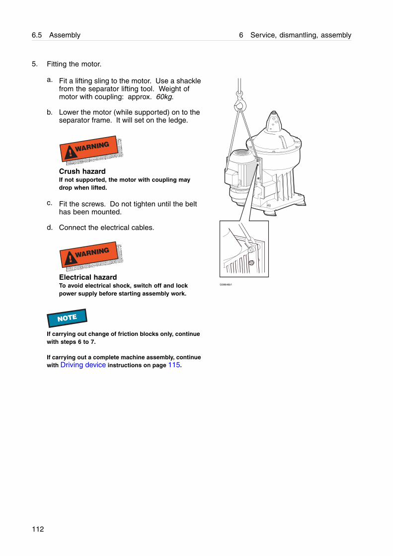
6.5 Assembly 6 Service, dismantling, assembly
5. Fitting the motor.
a. Fit a lifting sling to the motor. Use a shacklefrom the separator lifting tool. Weight ofmotor with coupling: approx. 60kg.
b. Lower the motor (while supported) on to theseparator frame. It will set on the ledge.
! WARNING
Crush hazardIf not supported, the motor with coupling maydrop when lifted.
c. Fit the screws. Do not tighten until the belthas been mounted.
d. Connect the electrical cables.
! WARNING
Electrical hazardTo avoid electrical shock, switch off and lockpower supply before starting assembly work.
G08646b1
NOTE
If carrying out change of friction blocks only, continuewith steps 6 to 7.
If carrying out a complete machine assembly, continuewith Driving device instructions on page 115.
112
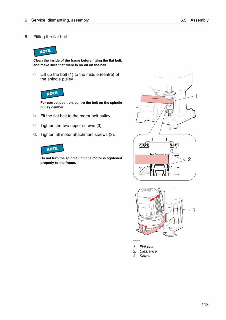
6 Service, dismantling, assembly 6.5 Assembly
6. Fitting the flat belt.
NOTE
Clean the inside of the frame before fitting the flat belt,and make sure that there is no oil on the belt.
a. Lift up the belt (1) to the middle (centre) ofthe spindle pulley.
NOTE
For correct position, centre the belt on the spindlepulley camber.
b. Fit the flat belt to the motor belt pulley.
c. Tighten the two upper screws (3).
d. Tighten all motor attachment screws (3).
NOTE
Do not turn the spindle until the motor is tightenedproperly to the frame.
2
3
1
G08588T1
1. Flat belt2. Clearance3. Screw
113
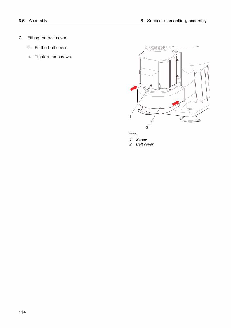
6.5 Assembly 6 Service, dismantling, assembly
7. Fitting the belt cover.
a. Fit the belt cover.
b. Tighten the screws.
1
2G08581A1
1. Screw2. Belt cover
114
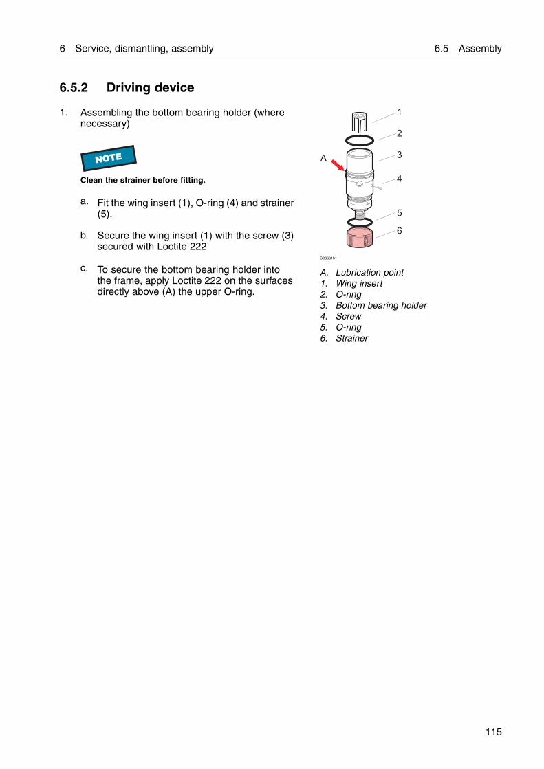
6 Service, dismantling, assembly 6.5 Assembly
6.5.2 Driving device
1. Assembling the bottom bearing holder (wherenecessary)
NOTE
Clean the strainer before fitting.
a. Fit the wing insert (1), O-ring (4) and strainer(5).
b. Secure the wing insert (1) with the screw (3)secured with Loctite 222
c. To secure the bottom bearing holder intothe frame, apply Loctite 222 on the surfacesdirectly above (A) the upper O-ring.
G08661h1
A. Lubrication point1. Wing insert2. O-ring3. Bottom bearing holder4. Screw5. O-ring6. Strainer
115
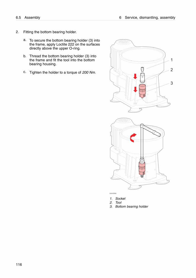
6.5 Assembly 6 Service, dismantling, assembly
2. Fitting the bottom bearing holder.
a. To secure the bottom bearing holder (3) intothe frame, apply Loctite 222 on the surfacesdirectly above the upper O-ring.
b. Thread the bottom bearing holder (3) intothe frame and fit the tool into the bottombearing housing.
c. Tighten the holder to a torque of 200 Nm.
G10157051
1. Socket2. Tool3. Bottom bearing holder
116
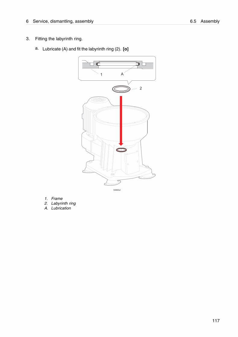
6 Service, dismantling, assembly 6.5 Assembly
3. Fitting the labyrinth ring.
a. Lubricate (A) and fit the labyrinth ring (2). [o]
G08663a1
1. Frame2. Labyrinth ringA. Lubrication
117
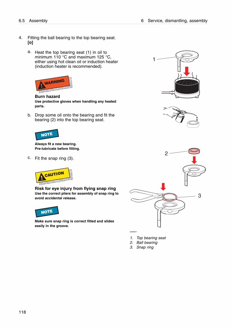
6.5 Assembly 6 Service, dismantling, assembly
4. Fitting the ball bearing to the top bearing seat.[o]
a. Heat the top bearing seat (1) in oil tominimum 110 °C and maximum 125 °C,either using hot clean oil or induction heater(induction heater is recommended).
! WARNING
Burn hazardUse protective gloves when handling any heatedparts.
b. Drop some oil onto the bearing and fit thebearing (2) into the top bearing seat.
NOTE
Always fit a new bearing.Pre-lubricate before fitting.
c. Fit the snap ring (3).
! CAUTION
Risk for eye injury from flying snap ringUse the correct pliers for assembly of snap ring toavoid accidental release.
NOTE
Make sure snap ring is correct fitted and slideseasily in the groove.
3
2
1
G0984871
1. Top bearing seat2. Ball bearing3. Snap ring
118
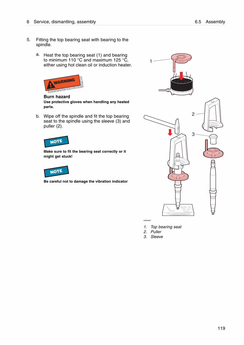
6 Service, dismantling, assembly 6.5 Assembly
5. Fitting the top bearing seat with bearing to thespindle.
a. Heat the top bearing seat (1) and bearingto minimum 110 °C and maximum 125 °C,either using hot clean oil or induction heater.
! WARNING
Burn hazardUse protective gloves when handling any heatedparts.
b. Wipe off the spindle and fit the top bearingseat to the spindle using the sleeve (3) andpuller (2).
NOTE
Make sure to fit the bearing seat correctly or itmight get stuck!
NOTE
Be careful not to damage the vibration indicator
1
2
3
G0984881
1. Top bearing seat2. Puller3. Sleeve
119
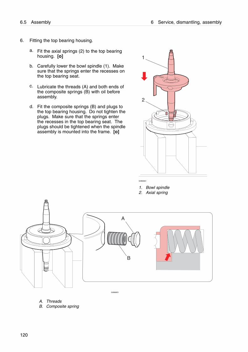
6.5 Assembly 6 Service, dismantling, assembly
6. Fitting the top bearing housing.
a. Fit the axial springs (2) to the top bearinghousing. [o]
b. Carefully lower the bowl spindle (1). Makesure that the springs enter the recesses onthe top bearing seat.
c. Lubricate the threads (A) and both ends ofthe composite springs (B) with oil beforeassembly.
d. Fit the composite springs (B) and plugs tothe top bearing housing. Do not tighten theplugs. Make sure that the springs enterthe recesses in the top bearing seat. Theplugs should be tightened when the spindleassembly is mounted into the frame. [o]
2
1
G0866661
1. Bowl spindle2. Axial spring
A
B
G0866651
A. ThreadsB. Composite spring
120
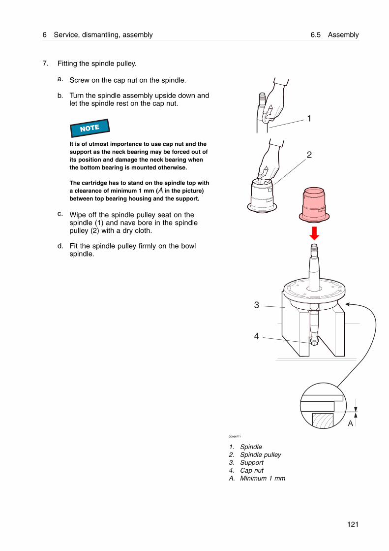
6 Service, dismantling, assembly 6.5 Assembly
7. Fitting the spindle pulley.
a. Screw on the cap nut on the spindle.
b. Turn the spindle assembly upside down andlet the spindle rest on the cap nut.
NOTE
It is of utmost importance to use cap nut and thesupport as the neck bearing may be forced out ofits position and damage the neck bearing whenthe bottom bearing is mounted otherwise.
The cartridge has to stand on the spindle top witha clearance of minimum 1 mm (A in the picture)between top bearing housing and the support.
c. Wipe off the spindle pulley seat on thespindle (1) and nave bore in the spindlepulley (2) with a dry cloth.
d. Fit the spindle pulley firmly on the bowlspindle.
2
3
4
1
A
G0866771
1. Spindle2. Spindle pulley3. Support4. Cap nutA. Minimum 1 mm
121
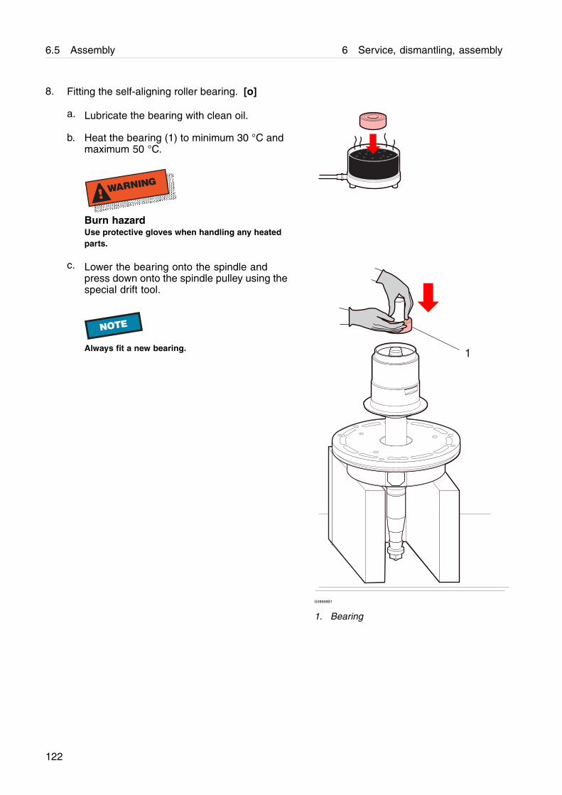
6.5 Assembly 6 Service, dismantling, assembly
8. Fitting the self-aligning roller bearing. [o]
a. Lubricate the bearing with clean oil.
b. Heat the bearing (1) to minimum 30 °C andmaximum 50 °C.
! WARNING
Burn hazardUse protective gloves when handling any heatedparts.
c. Lower the bearing onto the spindle andpress down onto the spindle pulley using thespecial drift tool.
NOTE
Always fit a new bearing. 1
G08668B1
1. Bearing
122
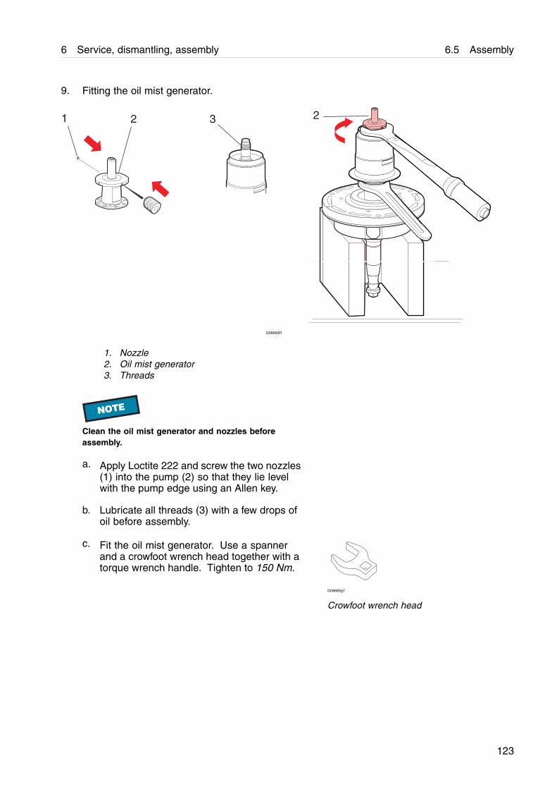
6 Service, dismantling, assembly 6.5 Assembly
9. Fitting the oil mist generator.
1 2 3 2
G08669f1
1. Nozzle2. Oil mist generator3. Threads
NOTE
Clean the oil mist generator and nozzles beforeassembly.
a. Apply Loctite 222 and screw the two nozzles(1) into the pump (2) so that they lie levelwith the pump edge using an Allen key.
b. Lubricate all threads (3) with a few drops ofoil before assembly.
c. Fit the oil mist generator. Use a spannerand a crowfoot wrench head together with atorque wrench handle. Tighten to 150 Nm.
G08669g1
Crowfoot wrench head
123
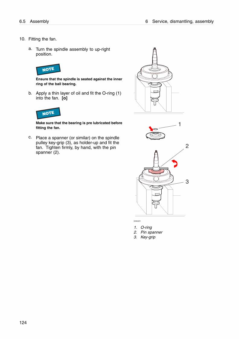
6.5 Assembly 6 Service, dismantling, assembly
10. Fitting the fan.
a. Turn the spindle assembly to up-rightposition.
NOTE
Ensure that the spindle is seated against the innerring of the ball bearing.
b. Apply a thin layer of oil and fit the O-ring (1)into the fan. [o]
NOTE
Make sure that the bearing is pre lubricated beforefitting the fan.
c. Place a spanner (or similar) on the spindlepulley key-grip (3), as holder-up and fit thefan. Tighten firmly, by hand, with the pinspanner (2).
2
1
3
G09240f1
1. O-ring2. Pin spanner3. Key-grip
124
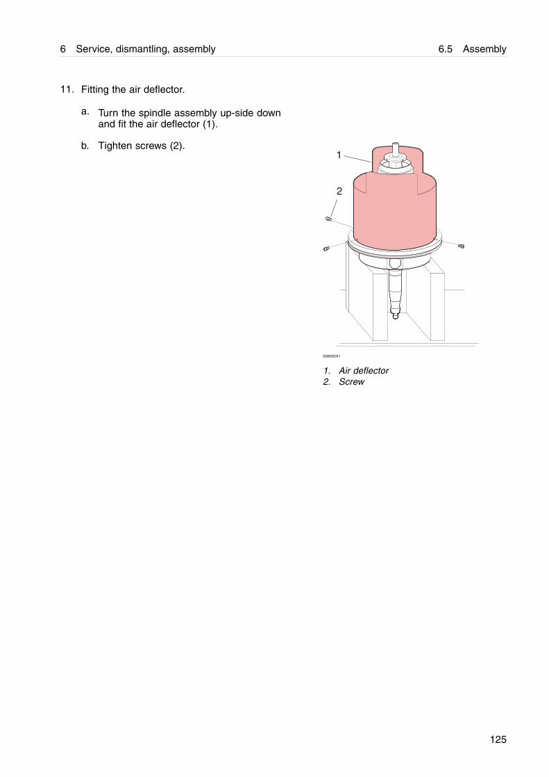
6 Service, dismantling, assembly 6.5 Assembly
11. Fitting the air deflector.
a. Turn the spindle assembly up-side downand fit the air deflector (1).
b. Tighten screws (2).1
2
G08592A1
1. Air deflector2. Screw
125
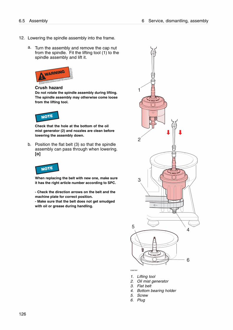
6.5 Assembly 6 Service, dismantling, assembly
12. Lowering the spindle assembly into the frame.
a. Turn the assembly and remove the cap nutfrom the spindle. Fit the lifting tool (1) to thespindle assembly and lift it.
! WARNING
Crush hazardDo not rotate the spindle assembly during lifting.The spindle assembly may otherwise come loosefrom the lifting tool.
NOTE
Check that the hole at the bottom of the oilmist generator (2) and nozzles are clean beforelowering the assembly down.
b. Position the flat belt (3) so that the spindleassembly can pass through when lowering.[o]
NOTE
When replacing the belt with new one, make sureit has the right article number according to SPC.
- Check the direction arrows on the belt and themachine plate for correct position.- Make sure that the belt does not get smudgedwith oil or grease during handling.
2
1
3
45
6
G0867981
1. Lifting tool2. Oil mist generator3. Flat belt4. Bottom bearing holder5. Screw6. Plug
126

6 Service, dismantling, assembly 6.5 Assembly
c. Carefully lower the spindle assembly andposition the bolt holes over the threadedframe holes. Make sure that the bottombearing, enters the bottom bearing holder(4) correctly. Do not use force.
! WARNING
Cut hazardDo not put fingers between the frame and airdeflector while lowering the assembly.
d. Fit and tighten the screws (5).
e. Firmly tighten the plugs (6) crosswise.
127
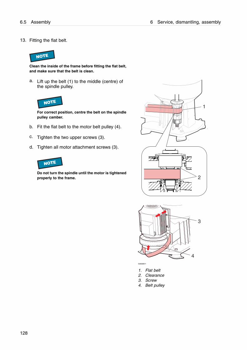
6.5 Assembly 6 Service, dismantling, assembly
13. Fitting the flat belt.
NOTE
Clean the inside of the frame before fitting the flat belt,and make sure that the belt is clean.
a. Lift up the belt (1) to the middle (centre) ofthe spindle pulley.
NOTE
For correct position, centre the belt on the spindlepulley camber.
b. Fit the flat belt to the motor belt pulley (4).
c. Tighten the two upper screws (3).
d. Tighten all motor attachment screws (3).
NOTE
Do not turn the spindle until the motor is tightenedproperly to the frame.
4
3
1
2
G08588V1
1. Flat belt2. Clearance3. Screw4. Belt pulley
128
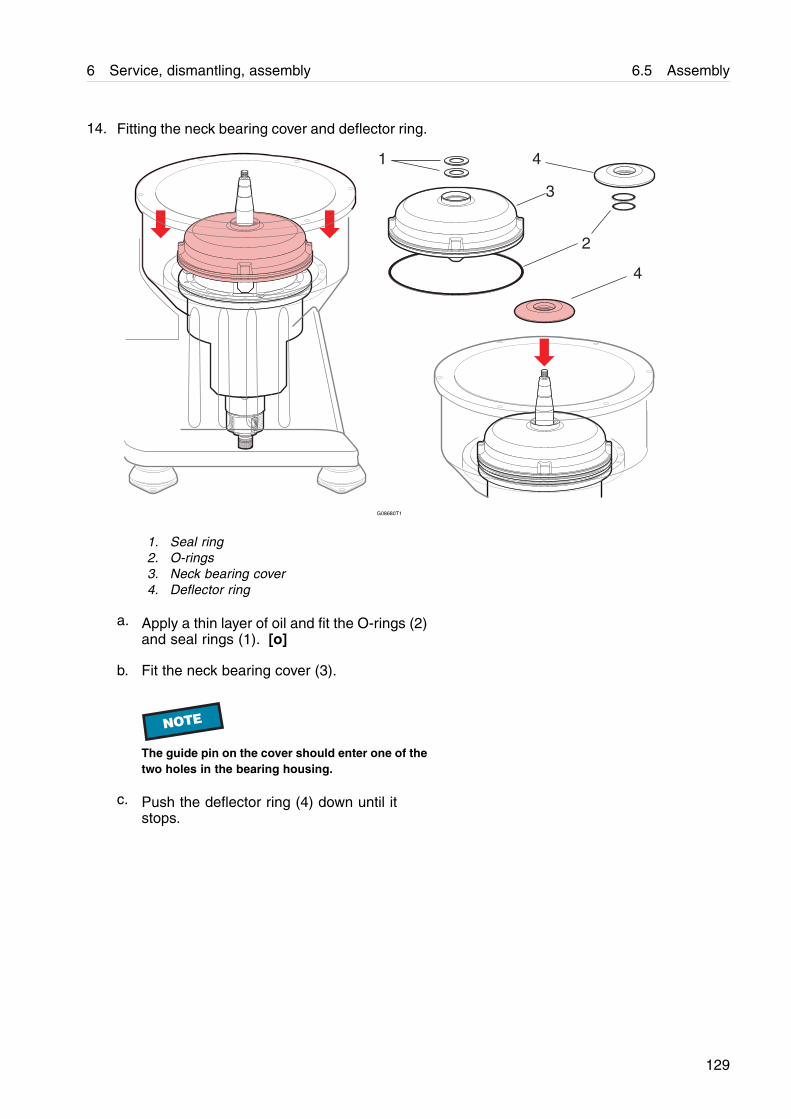
6 Service, dismantling, assembly 6.5 Assembly
14. Fitting the neck bearing cover and deflector ring.
G08680T1
1. Seal ring2. O-rings3. Neck bearing cover4. Deflector ring
a. Apply a thin layer of oil and fit the O-rings (2)and seal rings (1). [o]
b. Fit the neck bearing cover (3).
NOTE
The guide pin on the cover should enter one of thetwo holes in the bearing housing.
c. Push the deflector ring (4) down until itstops.
129
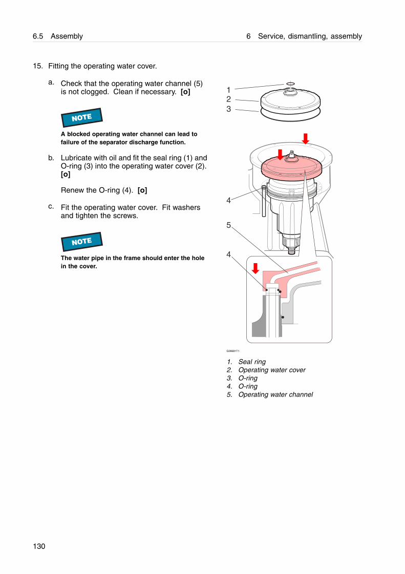
6.5 Assembly 6 Service, dismantling, assembly
15. Fitting the operating water cover.
a. Check that the operating water channel (5)is not clogged. Clean if necessary. [o]
NOTE
A blocked operating water channel can lead tofailure of the separator discharge function.
b. Lubricate with oil and fit the seal ring (1) andO-ring (3) into the operating water cover (2).[o]
Renew the O-ring (4). [o]
c. Fit the operating water cover. Fit washersand tighten the screws.
NOTE
The water pipe in the frame should enter the holein the cover.
1
3
4
2
4
5
G08681T1
1. Seal ring2. Operating water cover3. O-ring4. O-ring5. Operating water channel
130
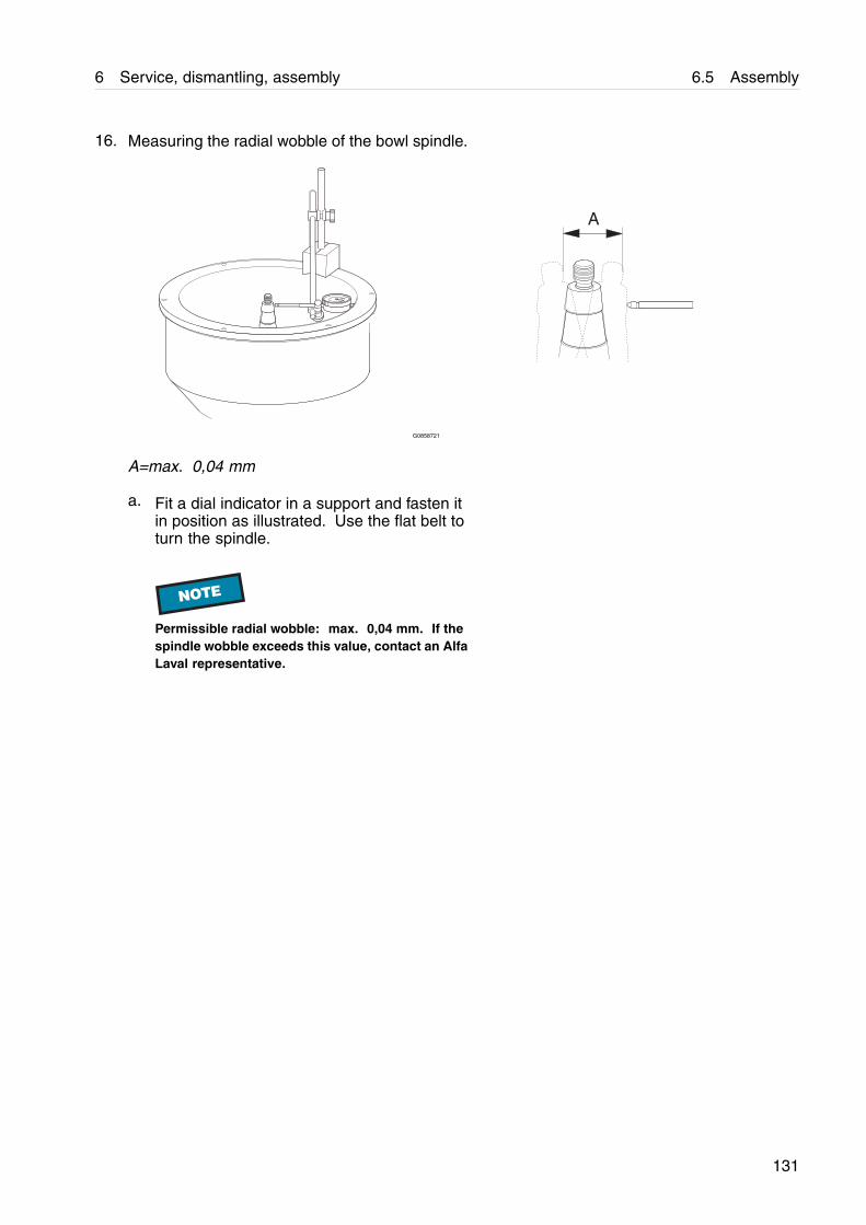
6 Service, dismantling, assembly 6.5 Assembly
16. Measuring the radial wobble of the bowl spindle.
A
G0858721
A=max. 0,04 mm
a. Fit a dial indicator in a support and fasten itin position as illustrated. Use the flat belt toturn the spindle.
NOTE
Permissible radial wobble: max. 0,04 mm. If thespindle wobble exceeds this value, contact an AlfaLaval representative.
131
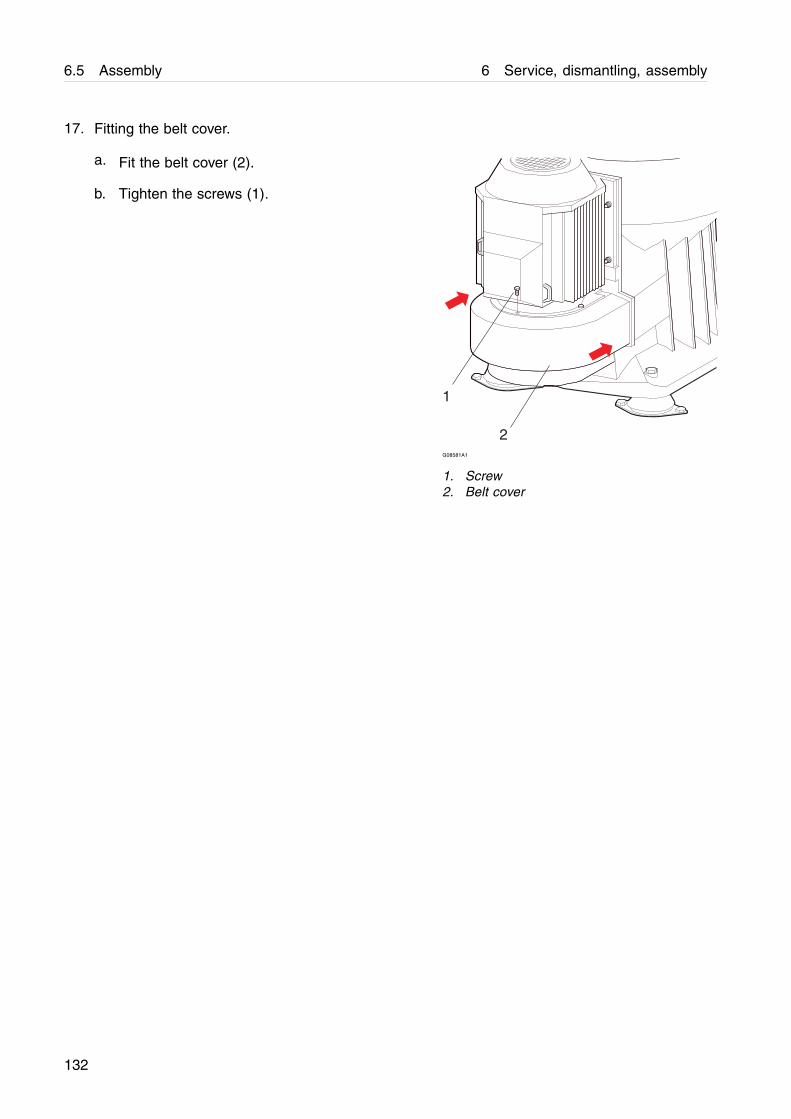
6.5 Assembly 6 Service, dismantling, assembly
17. Fitting the belt cover.
a. Fit the belt cover (2).
b. Tighten the screws (1).
1
2G08581A1
1. Screw2. Belt cover
132
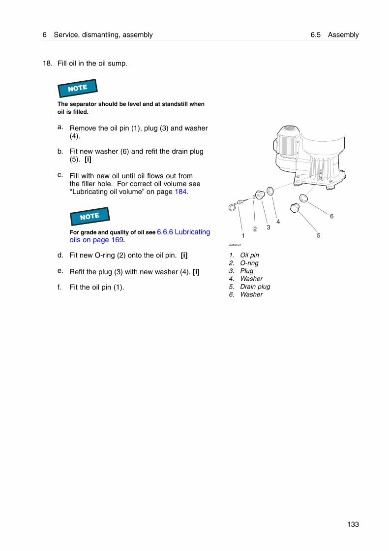
6 Service, dismantling, assembly 6.5 Assembly
18. Fill oil in the oil sump.
NOTE
The separator should be level and at standstill whenoil is filled.
a. Remove the oil pin (1), plug (3) and washer(4).
b. Fit new washer (6) and refit the drain plug(5). [i]
c. Fill with new oil until oil flows out fromthe filler hole. For correct oil volume see‘‘Lubricating oil volume” on page 184.
NOTE
For grade and quality of oil see 6.6.6 Lubricatingoils on page 169.
d. Fit new O-ring (2) onto the oil pin. [i]
e. Refit the plug (3) with new washer (4). [i]
f. Fit the oil pin (1).
12 3
4
5
6
G08687Z1
1. Oil pin2. O-ring3. Plug4. Washer5. Drain plug6. Washer
133
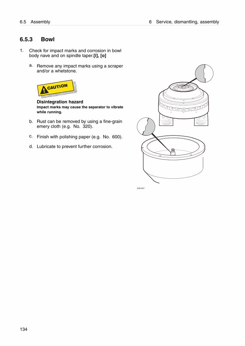
6.5 Assembly 6 Service, dismantling, assembly
6.5.3 Bowl
1. Check for impact marks and corrosion in bowlbody nave and on spindle taper.[i], [o]
a. Remove any impact marks using a scraperand/or a whetstone.
! CAUTION
Disintegration hazardImpact marks may cause the separator to vibratewhile running.
b. Rust can be removed by using a fine-grainemery cloth (e.g. No. 320).
c. Finish with polishing paper (e.g. No. 600).
d. Lubricate to prevent further corrosion.
G0874621
134

6 Service, dismantling, assembly 6.5 Assembly
2. Fitting new valve plugs on the operating slide. [i]
a. Carefully tap in new valve plugs, using aclean, soft-faced hammer.
NOTE
Make sure that the plugs are fitted as describedin the illustration.
G0874871
135
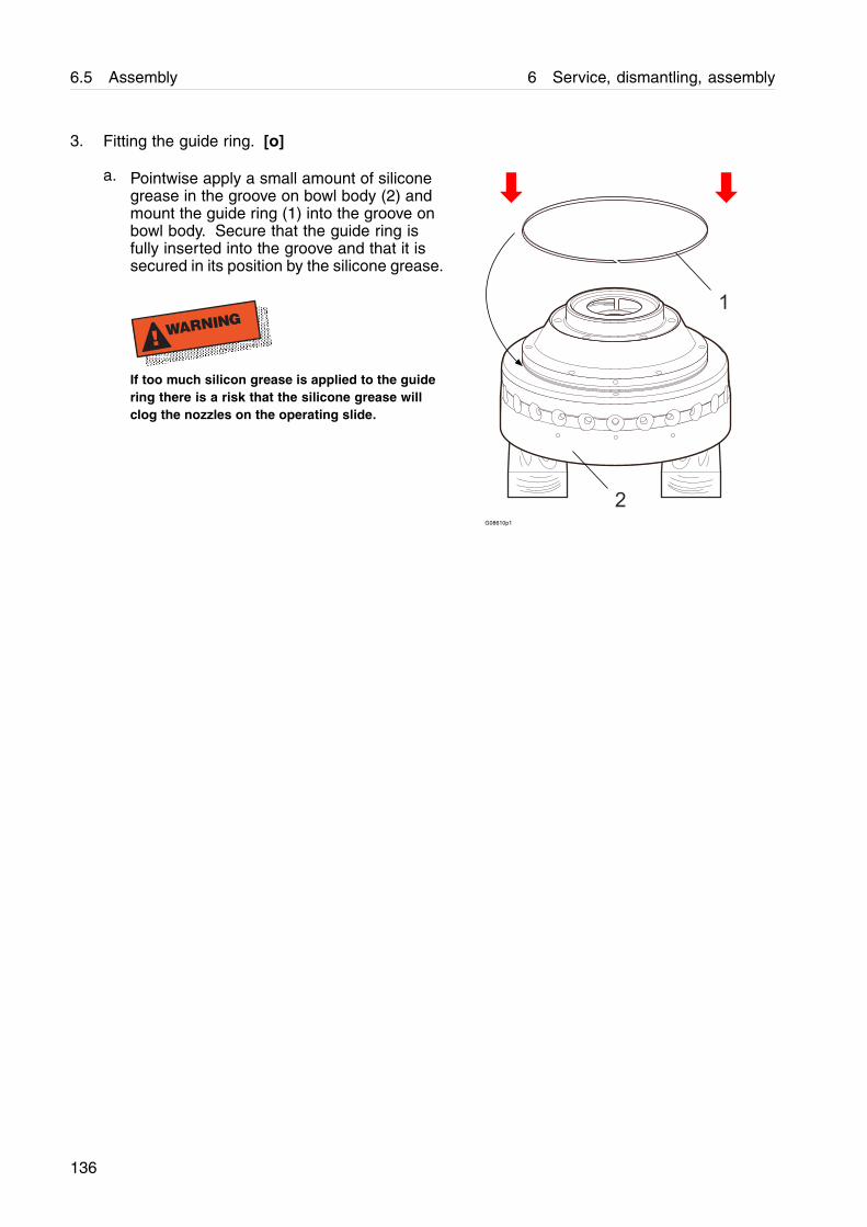
6.5 Assembly 6 Service, dismantling, assembly
3. Fitting the guide ring. [o]
a. Pointwise apply a small amount of siliconegrease in the groove on bowl body (2) andmount the guide ring (1) into the groove onbowl body. Secure that the guide ring isfully inserted into the groove and that it issecured in its position by the silicone grease.
! WARNING
If too much silicon grease is applied to the guidering there is a risk that the silicone grease willclog the nozzles on the operating slide.
G08610p1
136
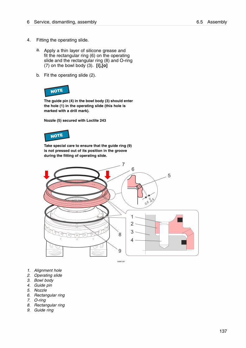
6 Service, dismantling, assembly 6.5 Assembly
4. Fitting the operating slide.
a. Apply a thin layer of silicone grease andfit the rectangular ring (6) on the operatingslide and the rectangular ring (8) and O-ring(7) on the bowl body (3). [i],[o]
b. Fit the operating slide (2).
NOTE
The guide pin (4) in the bowl body (3) should enterthe hole (1) in the operating slide (this hole ismarked with a drill mark).
Nozzle (5) secured with Loctite 243
NOTE
Take special care to ensure that the guide ring (9)is not pressed out of its position in the grooveduring the fitting of operating slide.
G0861261
1. Alignment hole2. Operating slide3. Bowl body4. Guide pin5. Nozzle6. Rectangular ring7. O-ring8. Rectangular ring9. Guide ring
137

6.5 Assembly 6 Service, dismantling, assembly
5. Fitting the operating slide holder.
a. Fit the holder (1) over the operating slide.
b. Apply a thin layer of molykote grease and fitand tighten new screws (2) and washers (3)to a torque of 30 ± 2 Nm. [i], [o]
NOTE
It is very important NOT to refit used screws andwashers. Always fit new ones included in theInspection kit!
Every washer (3) consists of two parts which mustbe correctly locked together.
13 2
G0861351
1. Holder2. Screw3. Washer
138
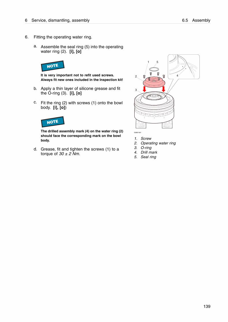
6 Service, dismantling, assembly 6.5 Assembly
6. Fitting the operating water ring.
a. Assemble the seal ring (5) into the operatingwater ring (2). [i], [o]
NOTE
It is very important not to refit used screws.Always fit new ones included in the Inspection kit!
b. Apply a thin layer of silicone grease and fitthe O-ring (3). [i], [o]
c. Fit the ring (2) with screws (1) onto the bowlbody. [i], [o])
NOTE
The drilled assembly mark (4) on the water ring (2)should face the corresponding mark on the bowlbody.
d. Grease, fit and tighten the screws (1) to atorque of 30 ± 2 Nm.
1
2
3
4
5
G0861461
1. Screw2. Operating water ring3. O-ring4. Drill mark5. Seal ring
139
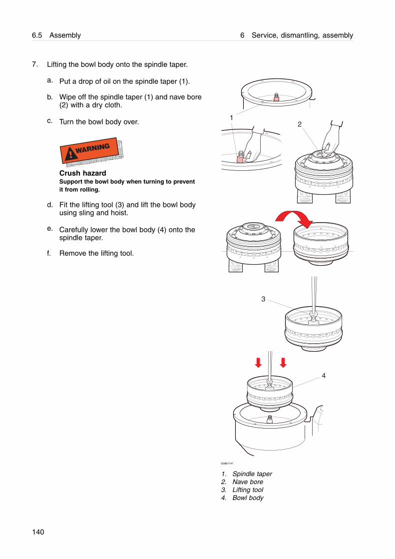
6.5 Assembly 6 Service, dismantling, assembly
7. Lifting the bowl body onto the spindle taper.
a. Put a drop of oil on the spindle taper (1).
b. Wipe off the spindle taper (1) and nave bore(2) with a dry cloth.
c. Turn the bowl body over.
! WARNING
Crush hazardSupport the bowl body when turning to preventit from rolling.
d. Fit the lifting tool (3) and lift the bowl bodyusing sling and hoist.
e. Carefully lower the bowl body (4) onto thespindle taper.
f. Remove the lifting tool.
1
3
2
4
G0861741
1. Spindle taper2. Nave bore3. Lifting tool4. Bowl body
140
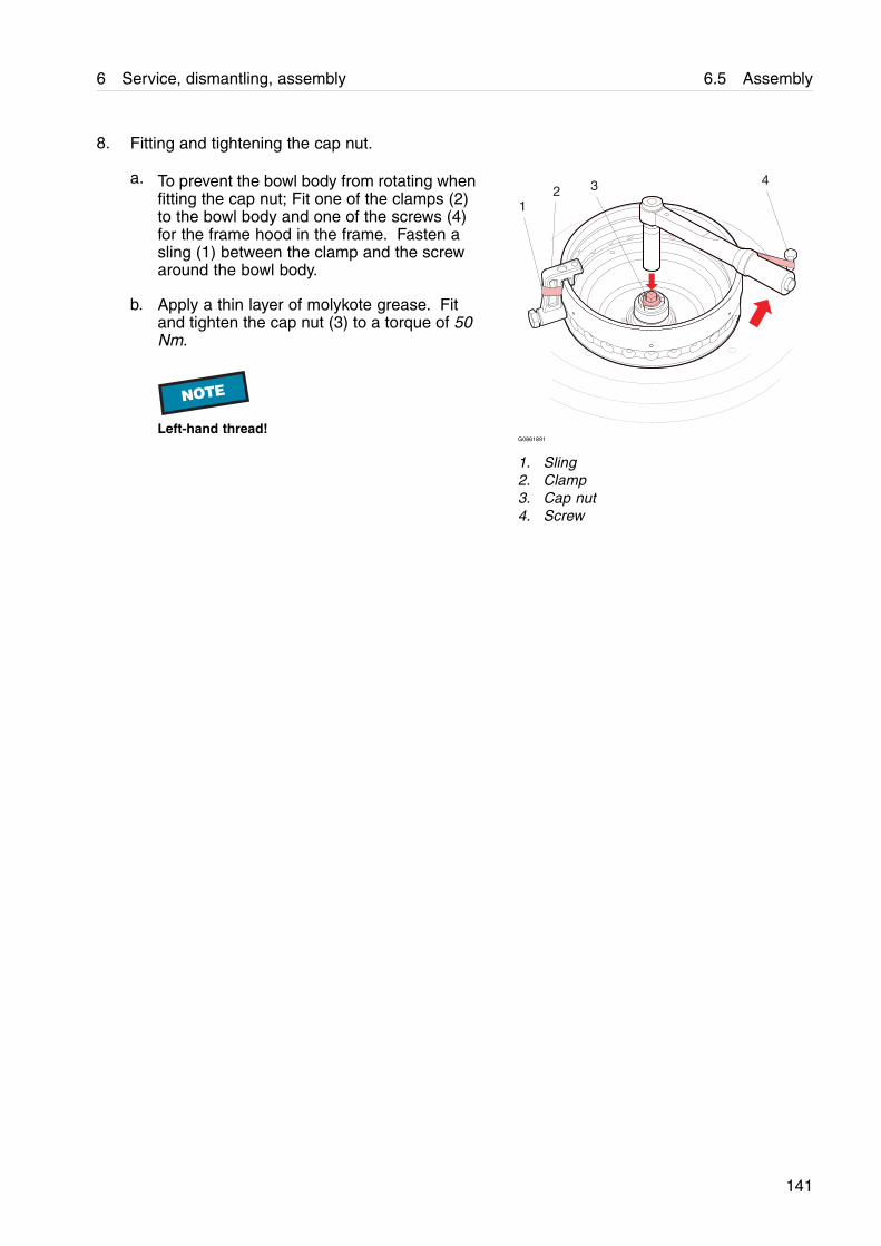
6 Service, dismantling, assembly 6.5 Assembly
8. Fitting and tightening the cap nut.
a. To prevent the bowl body from rotating whenfitting the cap nut; Fit one of the clamps (2)to the bowl body and one of the screws (4)for the frame hood in the frame. Fasten asling (1) between the clamp and the screwaround the bowl body.
b. Apply a thin layer of molykote grease. Fitand tighten the cap nut (3) to a torque of 50Nm.
NOTE
Left-hand thread!
1
432
G0861891
1. Sling2. Clamp3. Cap nut4. Screw
141
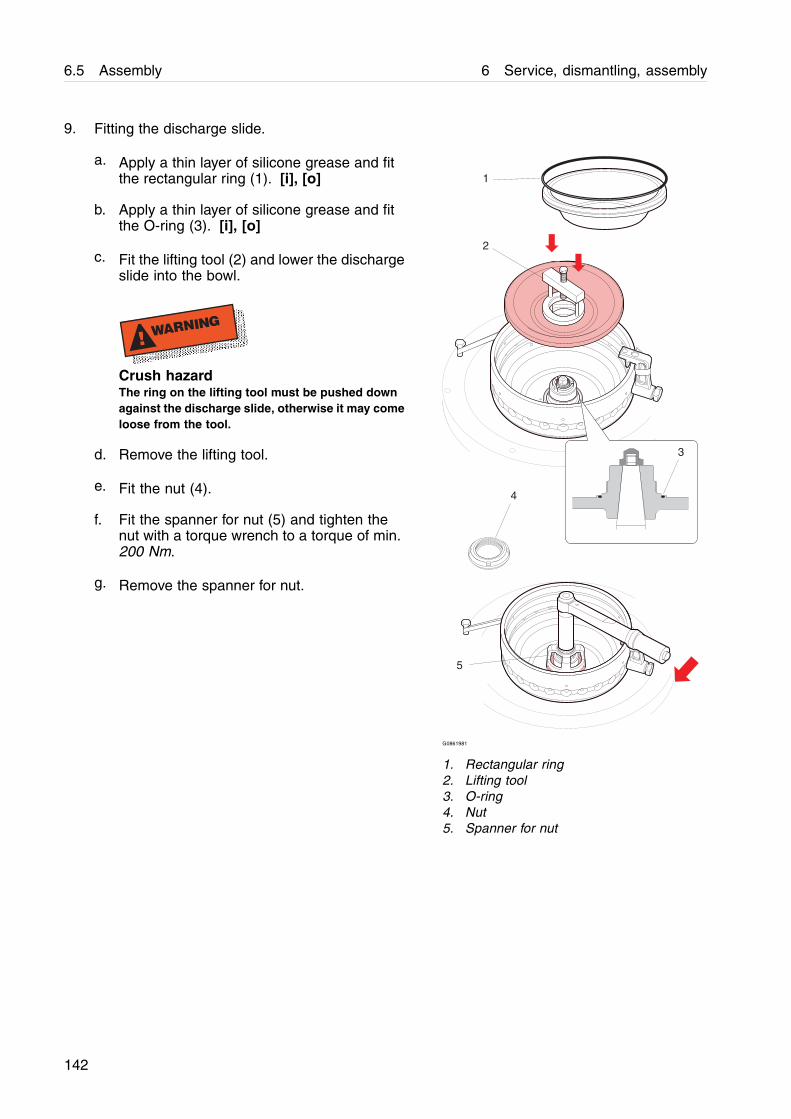
6.5 Assembly 6 Service, dismantling, assembly
9. Fitting the discharge slide.
a. Apply a thin layer of silicone grease and fitthe rectangular ring (1). [i], [o]
b. Apply a thin layer of silicone grease and fitthe O-ring (3). [i], [o]
c. Fit the lifting tool (2) and lower the dischargeslide into the bowl.
! WARNING
Crush hazardThe ring on the lifting tool must be pushed downagainst the discharge slide, otherwise it may comeloose from the tool.
d. Remove the lifting tool.
e. Fit the nut (4).
f. Fit the spanner for nut (5) and tighten thenut with a torque wrench to a torque of min.200 Nm.
g. Remove the spanner for nut.
1
2
3
4
5
G0861981
1. Rectangular ring2. Lifting tool3. O-ring4. Nut5. Spanner for nut
142
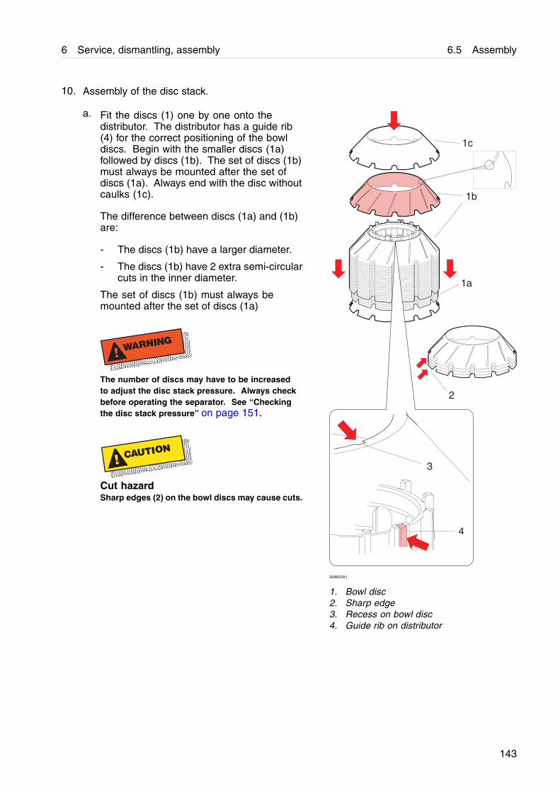
6 Service, dismantling, assembly 6.5 Assembly
10. Assembly of the disc stack.
a. Fit the discs (1) one by one onto thedistributor. The distributor has a guide rib(4) for the correct positioning of the bowldiscs. Begin with the smaller discs (1a)followed by discs (1b). The set of discs (1b)must always be mounted after the set ofdiscs (1a). Always end with the disc withoutcaulks (1c).
The difference between discs (1a) and (1b)are:
- The discs (1b) have a larger diameter.
- The discs (1b) have 2 extra semi-circularcuts in the inner diameter.
The set of discs (1b) must always bemounted after the set of discs (1a)
! WARNING
The number of discs may have to be increasedto adjust the disc stack pressure. Always checkbefore operating the separator. See ‘‘Checkingthe disc stack pressure” on page 151.
! CAUTION
Cut hazardSharp edges (2) on the bowl discs may cause cuts.
2
3
4
1b
1a
1c
G08620A1
1. Bowl disc2. Sharp edge3. Recess on bowl disc4. Guide rib on distributor
143
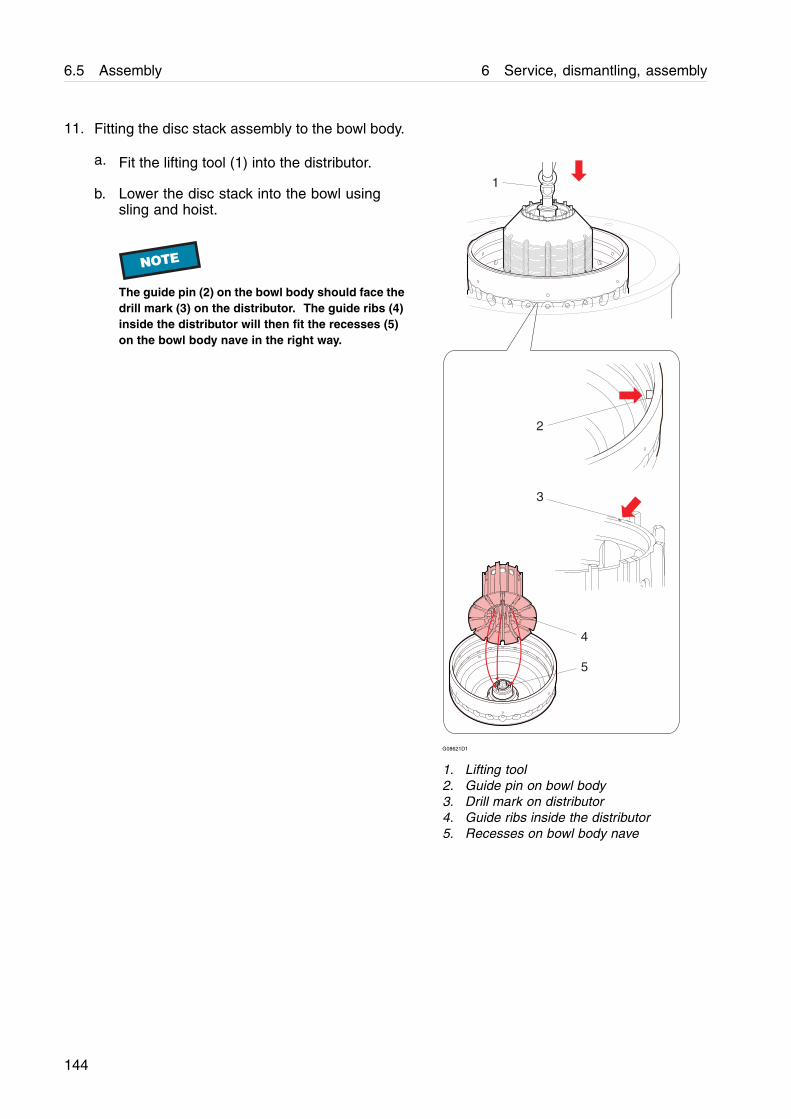
6.5 Assembly 6 Service, dismantling, assembly
11. Fitting the disc stack assembly to the bowl body.
a. Fit the lifting tool (1) into the distributor.
b. Lower the disc stack into the bowl usingsling and hoist.
NOTE
The guide pin (2) on the bowl body should face thedrill mark (3) on the distributor. The guide ribs (4)inside the distributor will then fit the recesses (5)on the bowl body nave in the right way.
1
2
3
4
5
G08621D1
1. Lifting tool2. Guide pin on bowl body3. Drill mark on distributor4. Guide ribs inside the distributor5. Recesses on bowl body nave
144
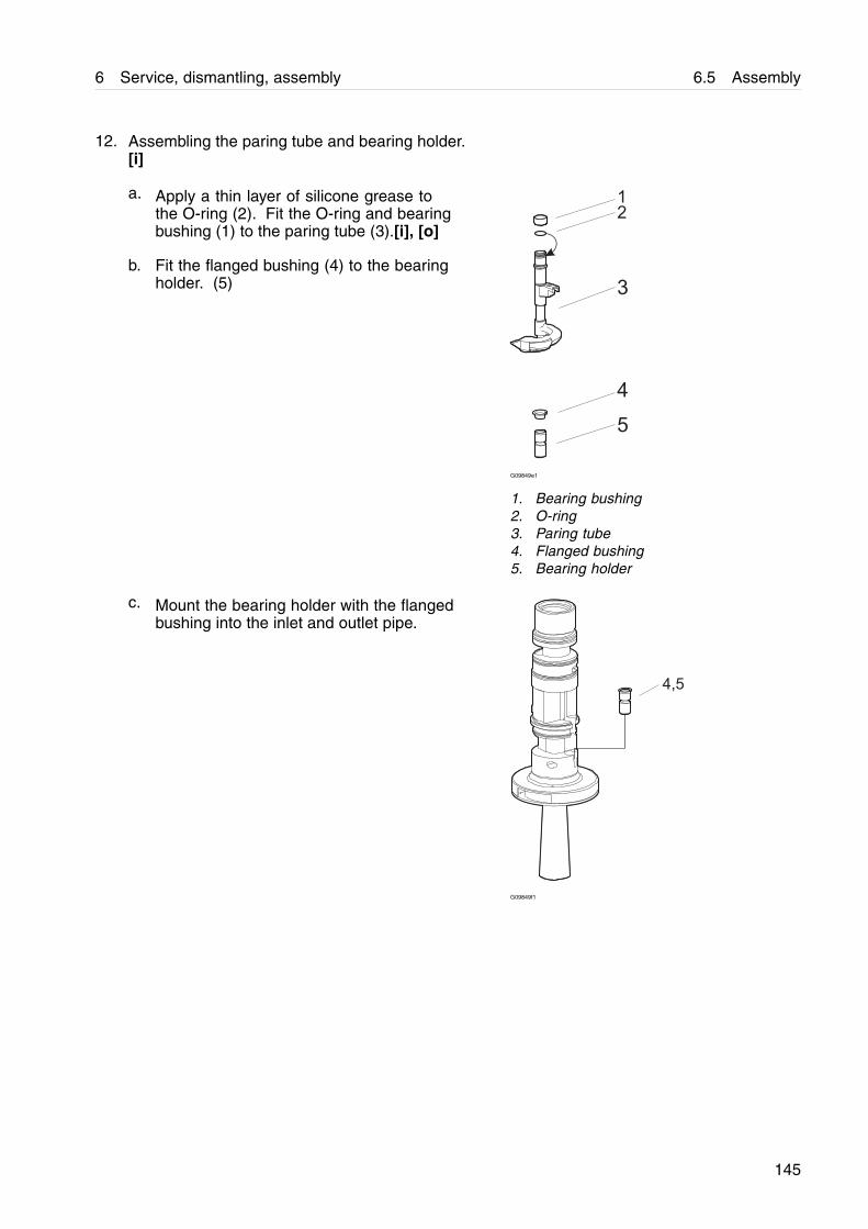
6 Service, dismantling, assembly 6.5 Assembly
12. Assembling the paring tube and bearing holder.[i]
a. Apply a thin layer of silicone grease tothe O-ring (2). Fit the O-ring and bearingbushing (1) to the paring tube (3).[i], [o]
b. Fit the flanged bushing (4) to the bearingholder. (5)
G09849e1
1. Bearing bushing2. O-ring3. Paring tube4. Flanged bushing5. Bearing holder
c. Mount the bearing holder with the flangedbushing into the inlet and outlet pipe.
G09849f1
145
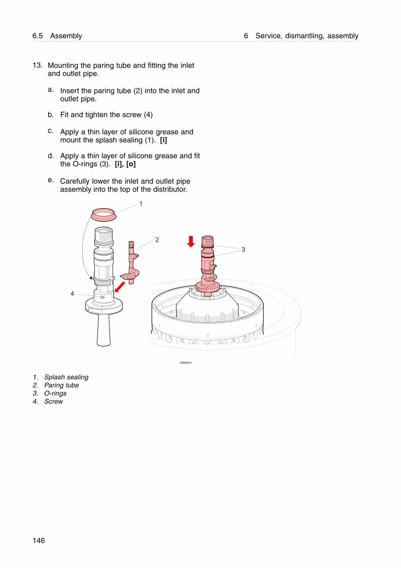
6.5 Assembly 6 Service, dismantling, assembly
13. Mounting the paring tube and fitting the inletand outlet pipe.
a. Insert the paring tube (2) into the inlet andoutlet pipe.
b. Fit and tighten the screw (4)
c. Apply a thin layer of silicone grease andmount the splash sealing (1). [i]
d. Apply a thin layer of silicone grease and fitthe O-rings (3). [i], [o]
e. Carefully lower the inlet and outlet pipeassembly into the top of the distributor.
G08622s1
1. Splash sealing2. Paring tube3. O-rings4. Screw
146
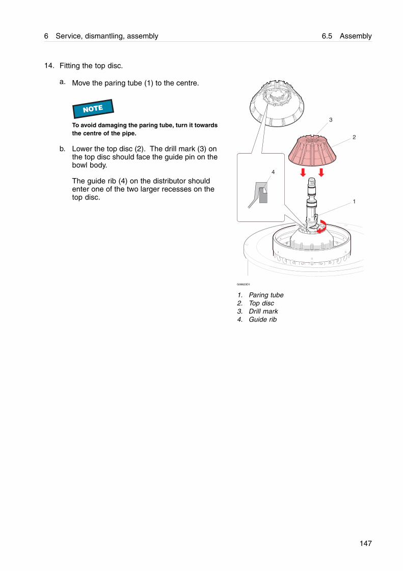
6 Service, dismantling, assembly 6.5 Assembly
14. Fitting the top disc.
a. Move the paring tube (1) to the centre.
NOTE
To avoid damaging the paring tube, turn it towardsthe centre of the pipe.
b. Lower the top disc (2). The drill mark (3) onthe top disc should face the guide pin on thebowl body.
The guide rib (4) on the distributor shouldenter one of the two larger recesses on thetop disc.
1
2
3
4
G08623D1
1. Paring tube2. Top disc3. Drill mark4. Guide rib
147
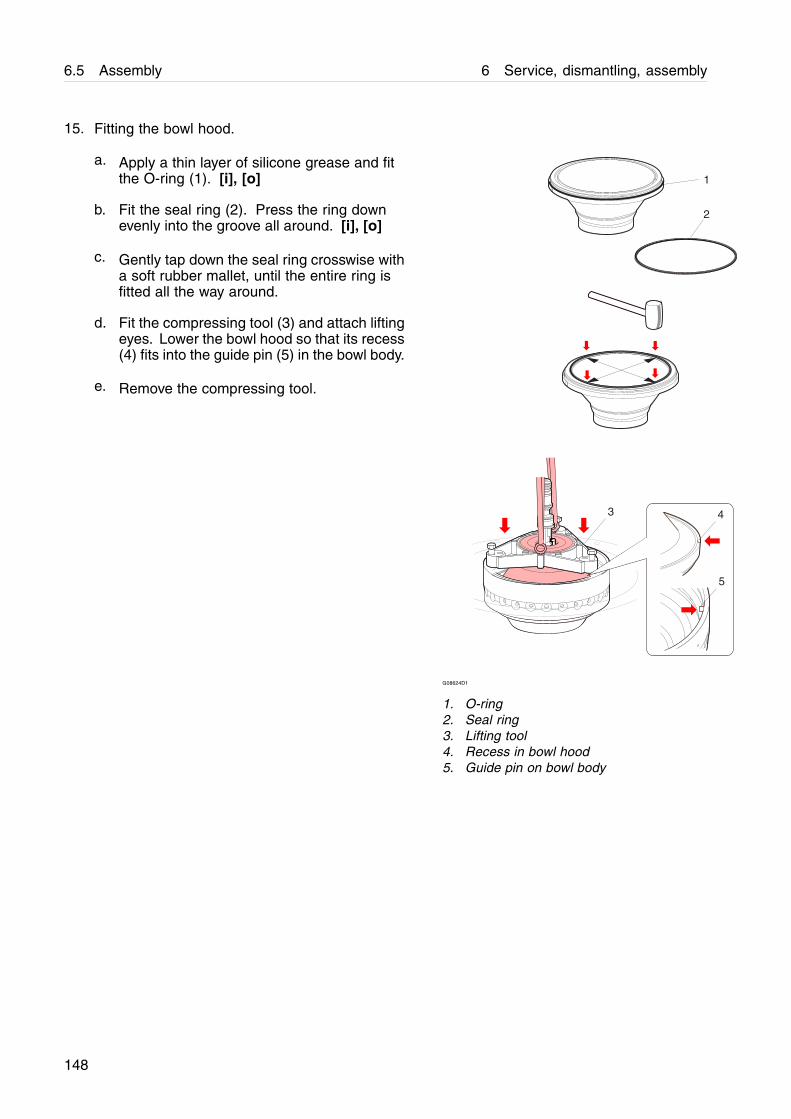
6.5 Assembly 6 Service, dismantling, assembly
15. Fitting the bowl hood.
a. Apply a thin layer of silicone grease and fitthe O-ring (1). [i], [o]
b. Fit the seal ring (2). Press the ring downevenly into the groove all around. [i], [o]
c. Gently tap down the seal ring crosswise witha soft rubber mallet, until the entire ring isfitted all the way around.
d. Fit the compressing tool (3) and attach liftingeyes. Lower the bowl hood so that its recess(4) fits into the guide pin (5) in the bowl body.
e. Remove the compressing tool.
1
2
3 4
5
G08624D1
1. O-ring2. Seal ring3. Lifting tool4. Recess in bowl hood5. Guide pin on bowl body
148

6 Service, dismantling, assembly 6.5 Assembly
16. Fitting the lock ring.
a. Place the lock ring (1) on the bowl hood(4) with its guide pin (5) close to thecorresponding hole (6) in the bowl body (2).
NOTE
Make sure that the groove in the bowl body whichretains the lock ring is clean.
b. Fit the compressing tool and compressthe disc stack by tightening the screws (3)alternately in increments of 5 Nm up to amaximum of 10 Nm until the lock ring fits intothe bowl body. Do not use excessive forceor any tool to knock the lock ring into thegroove. It must be possible to fit by hand.
For correct disc stack pressure see page151.
c. Make sure that the lock ring is fully engagedover it’s full length in the groove and doesnot flex anywhere. The lock ring ends mustbe facing each other with a gap betweenthem. The lock ring ends must not be flushor overlap each other.
NOTE
If there is not a gap between the lock ring ends,the lock ring is damaged and must be replacedwith a new one immediately
1
4
2
A B
1
2
3
5
6
C
G08625a1
1. Lock ring2. Bowl body3. Compressing tool screw4. Bowl hood5. Guide pin6. Hole for guide pinA. Before compressingB. Lock ring in positionC. Gap
149
6.5 Assembly 6 Service, dismantling, assembly
d. Measure gap C of lock ring and make sure itdoes not exceed 3 mm.
If the lock ring gap is greater than 3 mm, thelock ring is damaged and must be replacedwith a new one immediately.
! WARNING
Health hazardWelding of the lock ring is not allowed, as thiscan seriously affect the material strength. If thelock ring is either worn beyond the safety limitsor incorrectly assembled it may cause severedamage or fatal injury.
! WARNING
Health hazardNever remove any material from the lock ring.This may cause severe damage or fatal injury.
e. Release the pressure on the compressingtool and remove it.
150

6 Service, dismantling, assembly 6.5 Assembly
17. Checking the disc stack pressure. [i]
a. Remove bowl hood, top disc and inlet andoutlet pipe.
b. Add one disc (1) to the disc stack.
c. Refit the disc without caulks (2), the top discand bowl hood.
NOTE
Always refit the disc without caulks on top of thedisc stack!
d. Fit the lock ring (3) and fully compress thedisc stack with the compressing tool (4).
NOTE
Tighten the screws alternately in increments of 5Nm up to a maximum of 10 Nm.
e. If the lock ring enters the groove (5), repeatstep a-d until the lock ring does not enterthe groove.
f. Dismantle the bowl and remove one disc toget the correct disc stack pressure.
g. Assemble the bowl with inlet and outlet pipe.
12
4
3
5
G0874981
1. Bowl disc2. Disc without caulks3. Lock ring4. Compressing tool5. Groove
151
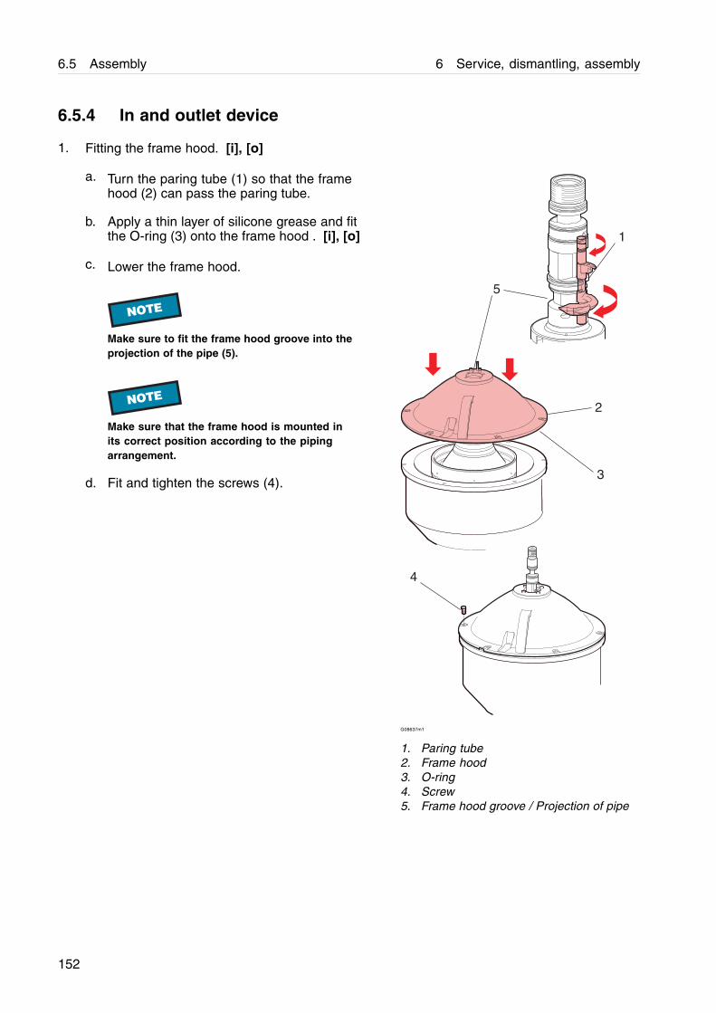
6.5 Assembly 6 Service, dismantling, assembly
6.5.4 In and outlet device
1. Fitting the frame hood. [i], [o]
a. Turn the paring tube (1) so that the framehood (2) can pass the paring tube.
b. Apply a thin layer of silicone grease and fitthe O-ring (3) onto the frame hood . [i], [o]
c. Lower the frame hood.
NOTE
Make sure to fit the frame hood groove into theprojection of the pipe (5).
NOTE
Make sure that the frame hood is mounted inits correct position according to the pipingarrangement.
d. Fit and tighten the screws (4).
G08637m1
1. Paring tube2. Frame hood3. O-ring4. Screw5. Frame hood groove / Projection of pipe
152

6 Service, dismantling, assembly 6.5 Assembly
2. Control measurement of paring disc height. [o]
Alfa Laval ref. 593336 Rev. 0
a. Remove the guide screw (A).
b. Measure the distance (D) through the screwhole.
Assemble the correct number of heightadjusting rings (B). (D) = 19 ± 0,5 mm.
c. Refit the guide screw (A)
G09115u1
A. Guide screwB. Height adjusting rings
153
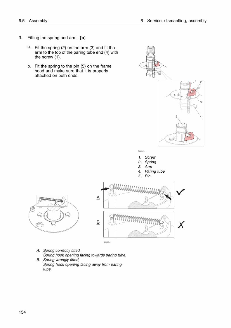
6.5 Assembly 6 Service, dismantling, assembly
3. Fitting the spring and arm. [o]
a. Fit the spring (2) on the arm (3) and fit thearm to the top of the paring tube end (4) withthe screw (1).
b. Fit the spring to the pin (5) on the framehood and make sure that it is properlyattached on both ends.
G08637n1
1. Screw2. Spring3. Arm4. Paring tube5. Pin
A
B
G08637r1
A. Spring correctly fitted,Spring hook opening facing towards paring tube.
B. Spring wrongly fitted,Spring hook opening facing away from paringtube.
154

6 Service, dismantling, assembly 6.5 Assembly
4. Fitting the connecting housing.
a. Lubricate the inlet pipe thread.
b. Fit the connecting housing (1) over theinlet/outlet pipe.
NOTE
Make sure that the screw, on top of the framehood, enters the guide hole at the underside ofthe connecting housing.
c. Lubricate the lock nut threads.
d. Fit the washer (3) and the lock nut (2) usingthe hook spanner.
NOTE
Fine threads on the pipe. Make sure that the locknut has entered the pipe threads correctly beforetightening with the hook spanner.
2
3
1
G08639a1
1. Connecting housing2. Lock nut3. Washer
155
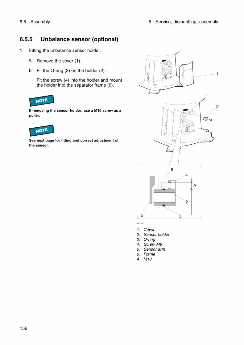
6.5 Assembly 6 Service, dismantling, assembly
6.5.5 Unbalance sensor (optional)
1. Fitting the unbalance sensor holder.
a. Remove the cover (1).
b. Fit the O-ring (3) on the holder (2).
Fit the screw (4) into the holder and mountthe holder into the separator frame (6).
NOTE
If removing the sensor holder; use a M10 screw as apuller.
NOTE
See next page for fitting and correct adjustment ofthe sensor.
1
2
3
2
4
A
6
5
G08734G1
1. Cover2. Sensor holder3. O-ring4. Screw M85. Sensor arm6. FrameA. M10
156
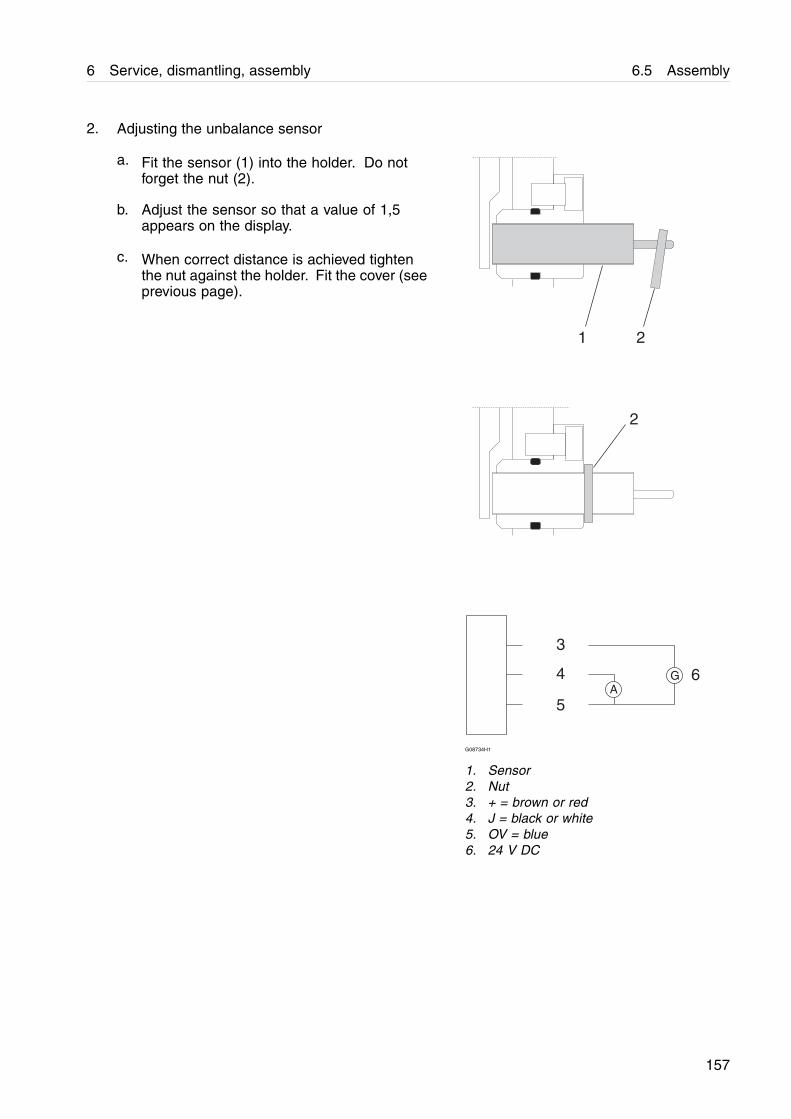
6 Service, dismantling, assembly 6.5 Assembly
2. Adjusting the unbalance sensor
a. Fit the sensor (1) into the holder. Do notforget the nut (2).
b. Adjust the sensor so that a value of 1,5appears on the display.
c. When correct distance is achieved tightenthe nut against the holder. Fit the cover (seeprevious page).
AG
21
2
3
4
5
6
G08734H1
1. Sensor2. Nut3. + = brown or red4. J = black or white5. OV = blue6. 24 V DC
157
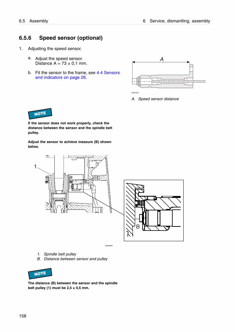
6.5 Assembly 6 Service, dismantling, assembly
6.5.6 Speed sensor (optional)
1. Adjusting the speed sensor.
a. Adjust the speed sensor.Distance A = 73 ± 0,1 mm.
b. Fit the sensor to the frame, see 4.4 Sensorsand indicators on page 26.
G08734E1
A. Speed sensor distance
NOTE
If the sensor does not work properly, check thedistance between the sensor and the spindle beltpulley.
Adjust the sensor to achieve measure (B) shownbelow.
B
1
G08588W1
1. Spindle belt pulleyB. Distance between sensor and pulley
NOTE
The distance (B) between the sensor and the spindlebelt pulley (1) must be 2,5 ± 0,5 mm.
158
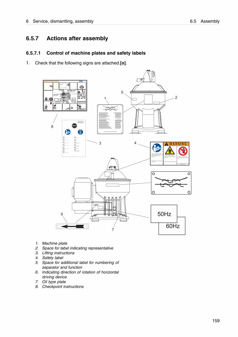
6 Service, dismantling, assembly 6.5 Assembly
6.5.7 Actions after assembly
6.5.7.1 Control of machine plates and safety labels
1. Check that the following signs are attached.[o].
50Hz
60Hz
Xxxxxx xx xxxx xxx xxx.
Xxxxxx xx xxxx xxx xxxxxx xxxx
xxx xxxxx.
Xxxxxx xx xxxx xxx xxxxxx xxxx
xxx xxxxx.
Xxxxxx xx xxxx xxx xxxxxx xxxx
xxx xxxxxxxx.
Xxxxxx xx xxxx xxx.
Xxxxxx xx xxxx xxx xxxxxx xxxx
xx xxxxxxxx.
Xxxxxx xx xxxx xxx xxxxxx xxxx
xx xxxxxxxx xxx xxx.
Xxxxxx xx xxxx xxx xxxxxx xxxx.
Xxxxxx xx xxxx xxx xxxxxx xxx
xx xxxxxxx xx xxxx.
Xxxxxx xx xxxx xxx x.
Xxxxxx xx xxxx xx xxxxxxx.
Xxxxxx xx xxxx xxx xxxxxx xxxx
xxxx xx.
Xxxxxx xx x Xxxxxx xx xxxxxx x xxxx
Xxxxxx xx xxxx xxx xxxxxx xxxx
xxxx xx xxx xxxxxxxx xxx xx.
XX
XX
XX
XX
XX
XX
XX
XX
XX
XX
XX
XX
XX
XXXXX XXX XXXX XXX XXXXX XXXX X
XXXX XXX XX.
XXX XXX X XXX XX XXXX XXXX XX X X
XXXXX XXX X XXX XXXX XXX XX XX X X
XXX X XXX.XX X XXXXX XX X XXXX XXX XXX X
XXXXXX XXX XXX XXX X XXXXX XXX X
XXXX .
XXXXXXXXXXXXXXXXXXXXX XXXX
XXXX XXXXXXXXXXXX XXX XXXXXXX
XXXXX XX XXXXX XXXXXXX
XXXXXXXXX.
XXXXXXX/XX,X XX
W A R N I N G
XXXXX X XXXXX XX X XXX XX XXX XXX XX
X.
!
21
3 4
5
7
6
8
1. Machine plate2. Space for label indicating representative3. Lifting instructions4. Safety label5. Space for additional label for numbering of
separator and function6. Indicating direction of rotation of horizontal
driving device7. Oil type plate8. Checkpoint instructions
159

6.5 Assembly 6 Service, dismantling, assembly
2. Check legibility.
Following texts should be read on the labels.
Machine plateSeparator typeSerial No / YearProduct NoMain group noConfiguration noDesignationMax. allowed speed (bowl)Direction of rotation (bowl)Speed motor shaftEl. current frequencyRecommended motor powerMax. density of feedMax. density of sedimentMax. density of operating liquidProcess temperature min./max.Inside diameter of bowl bodyManufacturerService enquiries: www.alfalaval.com
Safety labelText on label: Warning
Read the instruction manuals before installation, operationand maintenance. Consider inspection intervals.
Failure to strictly follow instructions can lead to fatal injury.
If excessive vibration occurs, stop separator and keep bowlfilled with liquid during rundown.
Out of balance vibration will become worse if bowl is not full.
Separator must stop rotating before any dismantling workis started.
Lifting instructionsText on label: Read instruction manual before lifting.
160
6 Service, dismantling, assembly 6.6 Oil change
6.6 Oil change
NOTE
The separator should be level and at standstill whenoil is filled or the oil level is checked
6.6.1 Lubricating oil
Do not mix different oil brands.
Always use clean vessels when handlinglubricating oil.
Great attention must be paid not to contaminatethe lubricating oil. Of particular importance is toavoid mixing of different types of oil. Even a fewdrops of motor oil mixed into a synthetic oil mayresult in severe foaming.
Any presence of black deposits in a mineraltype oil is an indication that the oil base hasdeteriorated seriously or that some of the oiladditives have precipitated. Always investigatewhy black deposits occurs.
If changing from one oil brand to another it isrecommended to do this in connection with anoverhaul of the separator. Clean the oil bathhousing and the spindle parts thoroughly andremove all deposits before filling the new oil.
NOTE
Always clean and dry parts (also tools) beforelubricants are applied.
! CAUTION
Check the oil level before start. Top up whennecessary. For correct oil volume, see “Lubricatingoil” in the table on page 184.
It is of utmost importance to use the lubricantsrecommended in our documentation.
161

6.6 Oil change 6 Service, dismantling, assembly
This does not exclude, however, the use of otherbrands, provided they have equivalently highquality properties as the brands recommended.The use of other oil brands and lubricantsthan recommended, is done on the exclusiveresponsibility of the user or oil supplier.
Applying, handling and storing of lubricants
Always be sure to follow lubricantsmanufacturer's instructions.
6.6.2 Check oil level
1. Remove the oil pin and make sure that the oillevel is above the lower end of the pin.
6.6.3 Oil change procedure
1. Remove the oil pin, plug and washer (B).
2. Place a vessel under the drain plug (C).
3. Remove the drain plug.
! CAUTION
Burn hazardThe lubricating oil and various machine surfaces canbe sufficiently hot to cause burns.
4. Collect the oil in the vessel.
5. Fit and tighten the drain plug (C).
6. Fill with new oil until oil flows out of oil filler hole(A).
NOTE
For grade and quality of oil, see 6.6.6 Lubricatingoils on page 169.
For correct oil volume, see “Lubricating oil” in thetable on page 184.
7. Fit the washer and the oil filling plug (B). Tightenthe plug.
8. Fit the oil pin.
B
A
Max.
C
Min.
G08687y1
A. Oil fillB. Plug and washerC. Oil drain plug
162
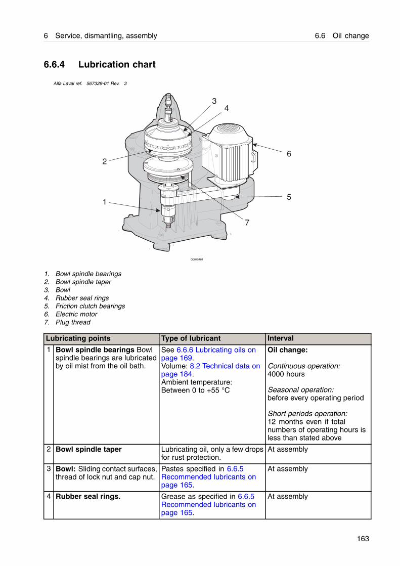
6 Service, dismantling, assembly 6.6 Oil change
6.6.4 Lubrication chart
Alfa Laval ref. 567329-01 Rev. 3
1
2
3
6
4
5
7
G0875481
1. Bowl spindle bearings2. Bowl spindle taper3. Bowl4. Rubber seal rings5. Friction clutch bearings6. Electric motor7. Plug thread
Lubricating points Type of lubricant Interval
1 Bowl spindle bearings Bowlspindle bearings are lubricatedby oil mist from the oil bath.
See 6.6.6 Lubricating oils onpage 169.Volume: 8.2 Technical data onpage 184.Ambient temperature:Between 0 to +55 °C
Oil change:
Continuous operation:4000 hours
Seasonal operation:before every operating period
Short periods operation:12 months even if totalnumbers of operating hours isless than stated above
2 Bowl spindle taper Lubricating oil, only a few dropsfor rust protection.
At assembly
3 Bowl: Sliding contact surfaces,thread of lock nut and cap nut.
Pastes specified in 6.6.5Recommended lubricants onpage 165.
At assembly
4 Rubber seal rings. Grease as specified in 6.6.5Recommended lubricants onpage 165.
At assembly
163

6.6 Oil change 6 Service, dismantling, assembly
Lubricating points Type of lubricant Interval
5 Friction clutch bearings The bearings are pre-lubricatedwith grease.
No need for extra lubrication.
6 Electric motor Follow the manufacturer’sinstructions.
Follow the manufacturer’sinstructions.
7 Plug thread(neck bearing assembly)
Lubricating oil. At assembly
NOTE
Check and pre-lubricate new spindle bearings andthose that have been out of service for one monthsor longer.
The lubrication chart can be complemented with moredetailed charts, showing the lubricating points indetail and what type of lubricants to use.
Instructions related to a specific design of the machinerefer to general assembly drawings
If not otherwise specified, follow the suppliersinstructions about applying, handling and storing oflubricants.
! CAUTION
Check the oil level before start.Top up when necessary.Do not overfill.Do not check the oil level when separator is running.
164
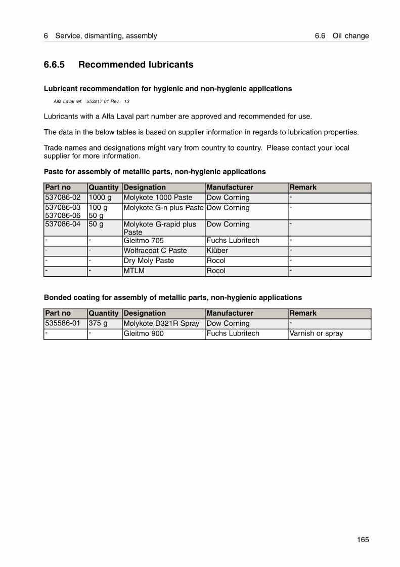
6 Service, dismantling, assembly 6.6 Oil change
6.6.5 Recommended lubricants
Lubricant recommendation for hygienic and non-hygienic applications
Alfa Laval ref. 553217 01 Rev. 13
Lubricants with a Alfa Laval part number are approved and recommended for use.
The data in the below tables is based on supplier information in regards to lubrication properties.
Trade names and designations might vary from country to country. Please contact your localsupplier for more information.
Paste for assembly of metallic parts, non-hygienic applications
Part no Quantity Designation Manufacturer Remark537086-02 1000 g Molykote 1000 Paste Dow Corning -
537086-03537086-06
100 g50 g
Molykote G-n plus Paste Dow Corning -
537086-04 50 g Molykote G-rapid plusPaste
Dow Corning -
- - Gleitmo 705 Fuchs Lubritech -- - Wolfracoat C Paste Klüber -- - Dry Moly Paste Rocol -- - MTLM Rocol -
Bonded coating for assembly of metallic parts, non-hygienic applications
Part no Quantity Designation Manufacturer Remark535586-01 375 g Molykote D321R Spray Dow Corning -- - Gleitmo 900 Fuchs Lubritech Varnish or spray
165
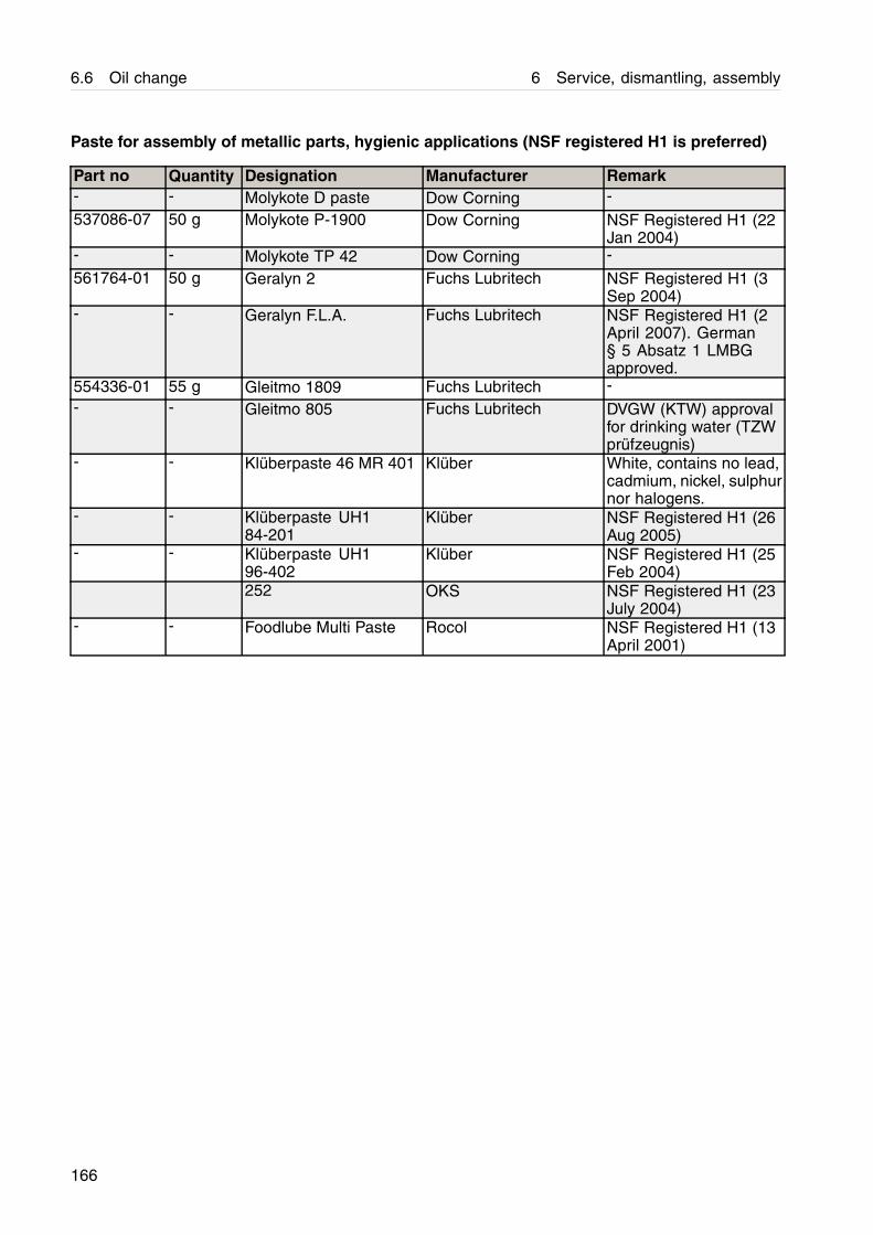
6.6 Oil change 6 Service, dismantling, assembly
Paste for assembly of metallic parts, hygienic applications (NSF registered H1 is preferred)
Part no Quantity Designation Manufacturer Remark- - Molykote D paste Dow Corning -
537086-07 50 g Molykote P-1900 Dow Corning NSF Registered H1 (22Jan 2004)
- - Molykote TP 42 Dow Corning -
561764-01 50 g Geralyn 2 Fuchs Lubritech NSF Registered H1 (3Sep 2004)
- - Geralyn F.L.A. Fuchs Lubritech NSF Registered H1 (2April 2007). German§ 5 Absatz 1 LMBGapproved.
554336-01 55 g Gleitmo 1809 Fuchs Lubritech -- - Gleitmo 805 Fuchs Lubritech DVGW (KTW) approval
for drinking water (TZWprüfzeugnis)
- - Klüberpaste 46 MR 401 Klüber White, contains no lead,cadmium, nickel, sulphurnor halogens.
- - Klüberpaste UH184-201
Klüber NSF Registered H1 (26Aug 2005)
- - Klüberpaste UH196-402
Klüber NSF Registered H1 (25Feb 2004)
252 OKS NSF Registered H1 (23July 2004)
- - Foodlube Multi Paste Rocol NSF Registered H1 (13April 2001)
166
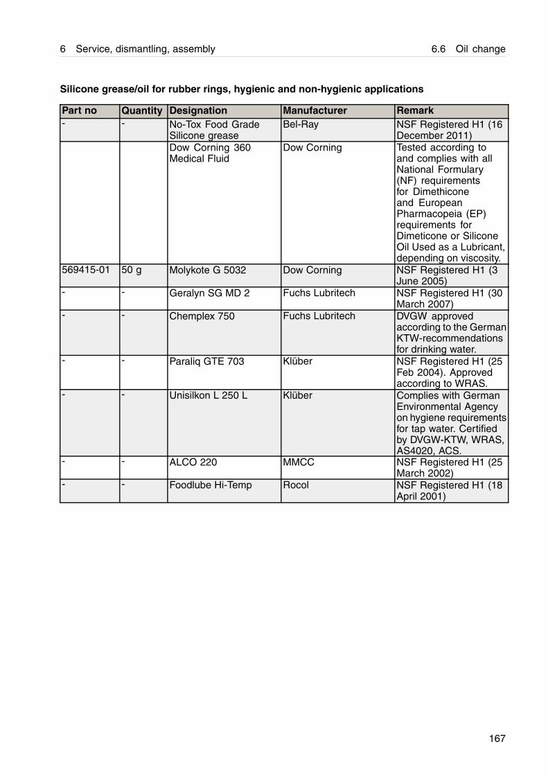
6 Service, dismantling, assembly 6.6 Oil change
Silicone grease/oil for rubber rings, hygienic and non-hygienic applications
Part no Quantity Designation Manufacturer Remark- - No-Tox Food Grade
Silicone greaseBel-Ray NSF Registered H1 (16
December 2011)Dow Corning 360Medical Fluid
Dow Corning Tested according toand complies with allNational Formulary(NF) requirementsfor Dimethiconeand EuropeanPharmacopeia (EP)requirements forDimeticone or SiliconeOil Used as a Lubricant,depending on viscosity.
569415-01 50 g Molykote G 5032 Dow Corning NSF Registered H1 (3June 2005)
- - Geralyn SG MD 2 Fuchs Lubritech NSF Registered H1 (30March 2007)
- - Chemplex 750 Fuchs Lubritech DVGW approvedaccording to the GermanKTW-recommendationsfor drinking water.
- - Paraliq GTE 703 Klüber NSF Registered H1 (25Feb 2004). Approvedaccording to WRAS.
- - Unisilkon L 250 L Klüber Complies with GermanEnvironmental Agencyon hygiene requirementsfor tap water. Certifiedby DVGW-KTW, WRAS,AS4020, ACS.
- - ALCO 220 MMCC NSF Registered H1 (25March 2002)
- - Foodlube Hi-Temp Rocol NSF Registered H1 (18April 2001)
167
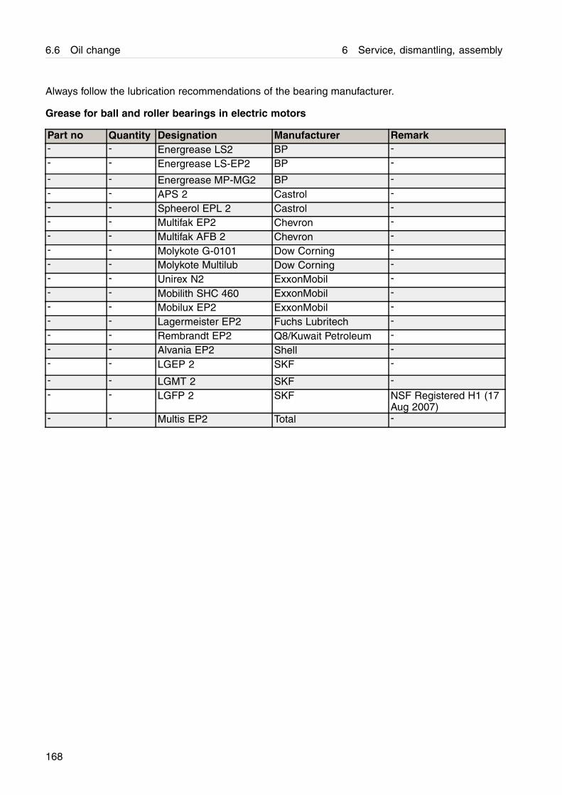
6.6 Oil change 6 Service, dismantling, assembly
Always follow the lubrication recommendations of the bearing manufacturer.
Grease for ball and roller bearings in electric motors
Part no Quantity Designation Manufacturer Remark- - Energrease LS2 BP -- - Energrease LS-EP2 BP -
- - Energrease MP-MG2 BP -- - APS 2 Castrol -- - Spheerol EPL 2 Castrol -- - Multifak EP2 Chevron -- - Multifak AFB 2 Chevron -- - Molykote G-0101 Dow Corning -- - Molykote Multilub Dow Corning -- - Unirex N2 ExxonMobil -- - Mobilith SHC 460 ExxonMobil -- - Mobilux EP2 ExxonMobil -- - Lagermeister EP2 Fuchs Lubritech -- - Rembrandt EP2 Q8/Kuwait Petroleum -- - Alvania EP2 Shell -- - LGEP 2 SKF -
- - LGMT 2 SKF -- - LGFP 2 SKF NSF Registered H1 (17
Aug 2007)- - Multis EP2 Total -
168
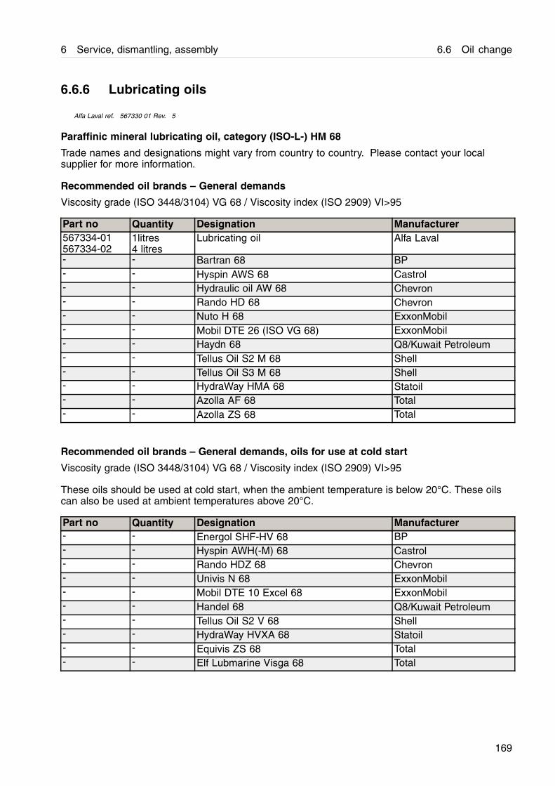
6 Service, dismantling, assembly 6.6 Oil change
6.6.6 Lubricating oils
Alfa Laval ref. 567330 01 Rev. 5
Paraffinic mineral lubricating oil, category (ISO-L-) HM 68
Trade names and designations might vary from country to country. Please contact your localsupplier for more information.
Recommended oil brands – General demands
Viscosity grade (ISO 3448/3104) VG 68 / Viscosity index (ISO 2909) VI>95
Part no Quantity Designation Manufacturer567334-01567334-02
1litres4 litres
Lubricating oil Alfa Laval
- - Bartran 68 BP- - Hyspin AWS 68 Castrol- - Hydraulic oil AW 68 Chevron- - Rando HD 68 Chevron- - Nuto H 68 ExxonMobil- - Mobil DTE 26 (ISO VG 68) ExxonMobil- - Haydn 68 Q8/Kuwait Petroleum- - Tellus Oil S2 M 68 Shell- - Tellus Oil S3 M 68 Shell- - HydraWay HMA 68 Statoil- - Azolla AF 68 Total- - Azolla ZS 68 Total
Recommended oil brands – General demands, oils for use at cold start
Viscosity grade (ISO 3448/3104) VG 68 / Viscosity index (ISO 2909) VI>95
These oils should be used at cold start, when the ambient temperature is below 20°C. These oilscan also be used at ambient temperatures above 20°C.
Part no Quantity Designation Manufacturer- - Energol SHF-HV 68 BP- - Hyspin AWH(-M) 68 Castrol- - Rando HDZ 68 Chevron- - Univis N 68 ExxonMobil- - Mobil DTE 10 Excel 68 ExxonMobil- - Handel 68 Q8/Kuwait Petroleum- - Tellus Oil S2 V 68 Shell- - HydraWay HVXA 68 Statoil- - Equivis ZS 68 Total- - Elf Lubmarine Visga 68 Total
169
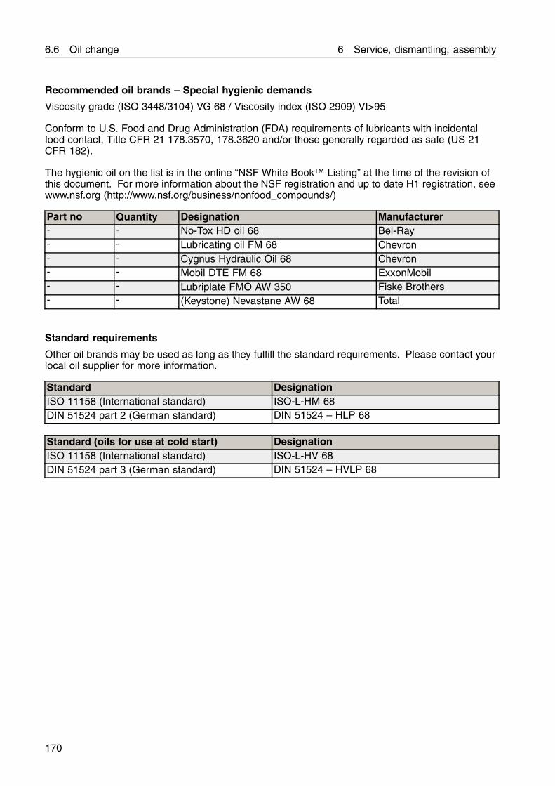
6.6 Oil change 6 Service, dismantling, assembly
Recommended oil brands – Special hygienic demands
Viscosity grade (ISO 3448/3104) VG 68 / Viscosity index (ISO 2909) VI>95
Conform to U.S. Food and Drug Administration (FDA) requirements of lubricants with incidentalfood contact, Title CFR 21 178.3570, 178.3620 and/or those generally regarded as safe (US 21CFR 182).
The hygienic oil on the list is in the online “NSF White Book™ Listing” at the time of the revision ofthis document. For more information about the NSF registration and up to date H1 registration, seewww.nsf.org (http://www.nsf.org/business/nonfood_compounds/)
Part no Quantity Designation Manufacturer- - No-Tox HD oil 68 Bel-Ray- - Lubricating oil FM 68 Chevron- - Cygnus Hydraulic Oil 68 Chevron- - Mobil DTE FM 68 ExxonMobil- - Lubriplate FMO AW 350 Fiske Brothers- - (Keystone) Nevastane AW 68 Total
Standard requirements
Other oil brands may be used as long as they fulfill the standard requirements. Please contact yourlocal oil supplier for more information.
Standard DesignationISO 11158 (International standard) ISO-L-HM 68DIN 51524 part 2 (German standard) DIN 51524 – HLP 68
Standard (oils for use at cold start) DesignationISO 11158 (International standard) ISO-L-HV 68DIN 51524 part 3 (German standard) DIN 51524 – HVLP 68
170
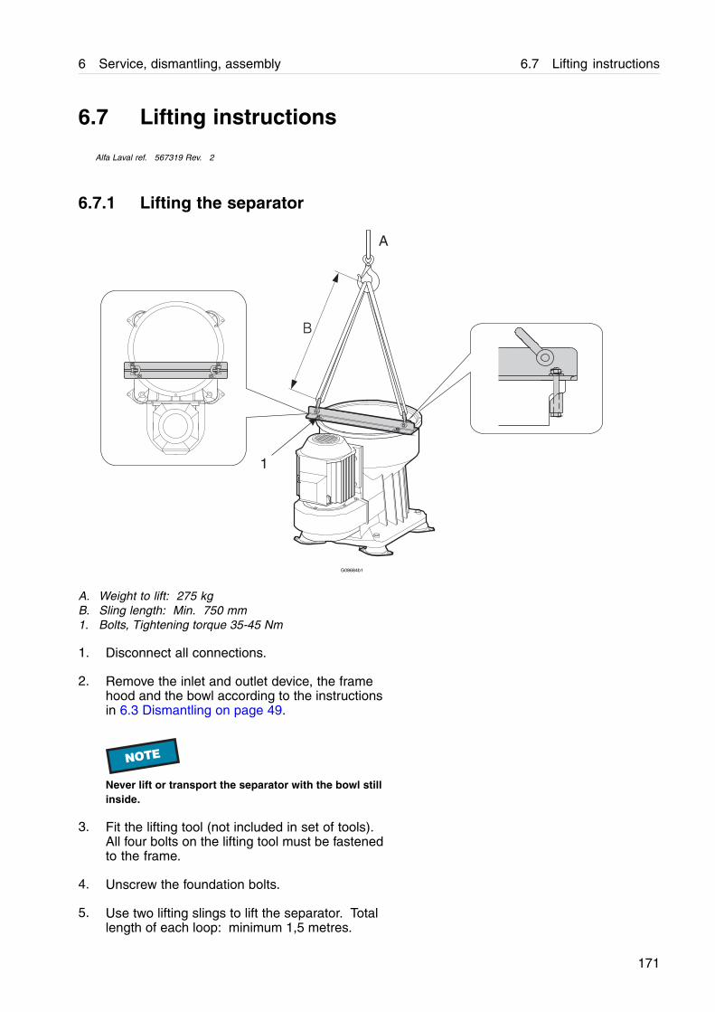
6 Service, dismantling, assembly 6.7 Lifting instructions
6.7 Lifting instructions
Alfa Laval ref. 567319 Rev. 2
6.7.1 Lifting the separator
1
A
B
G08684b1
A. Weight to lift: 275 kgB. Sling length: Min. 750 mm1. Bolts, Tightening torque 35-45 Nm
1. Disconnect all connections.
2. Remove the inlet and outlet device, the framehood and the bowl according to the instructionsin 6.3 Dismantling on page 49.
NOTE
Never lift or transport the separator with the bowl stillinside.
3. Fit the lifting tool (not included in set of tools).All four bolts on the lifting tool must be fastenedto the frame.
4. Unscrew the foundation bolts.
5. Use two lifting slings to lift the separator. Totallength of each loop: minimum 1,5 metres.
171

6.7 Lifting instructions 6 Service, dismantling, assembly
6. When lifting and moving the separator, follownormal safety precautions for lifting large heavyobjects.
! WARNING
Crush hazardA falling separator can cause accidents resulting inserious injury and damage.
Never lift the separator by any other method thandescribed in this manual.
NOTE
When lifting parts without weight specifications,always use lifting straps with the capacity of at least500 kg.
172

6 Service, dismantling, assembly 6.7 Lifting instructions
6.7.2 Lifting the bowl
When lifting and moving an assembled bowl,always follow these instructions.
1. Fit the lifting tool with lifting eyes to the bowlassembly.
2. Check that the lock ring is mounted correctlybefore lifting the complete bowl.
3. Lift the bowl using a sling with the proper rating.
NOTE
Never try to lift the bowl while it is still in the frame.The bowl body is fastened to the frame with the capnut.
2
1
A
G08684A1
1. Lifting eye, Tightening torque 40±5 Nm2. Lock ring (Make sure that lock ring is fitted.)
173

6.7 Lifting instructions 6 Service, dismantling, assembly
7 Fault finding
These fault finding instructions are for the separator only. If a fault occurs, study the SystemDocumentation fault finding section (if applicable).
7.1 Mechanical functions
7.1.1 Separator vibration
! WARNING
Disintegration hazardIf excessive vibration occurs, stop separator and keepbowl filled with liquid during rundown.The cause of the vibration must be identified andcorrected before the separator is restarted.
NOTE
Some vibration is normal during the starting andstopping sequences when the separator passesthrough its critical speed.
Cause Corrective action
Bowl out of balance due to:- poor cleaning- incorrect assembly- incorrect disc stack compression- bowl assembled with parts from otherseparators
Dismantle the separator and check the assemblyand cleaning.
Uneven sludge deposits in the sludge space. Dismantle and clean the separator bowl.
Height position of paring disc is incorrect. Stop the separator, measure, and if necessary,adjust the height.
Bowl spindle bent. Renew the bowl spindle.
Bearing(s) damaged or worn. Renew all bearings.
The frame feet are worn out. Renew the frame feet.
Spindle top bearing spring broken. Renew all springs.
175
7.1 Mechanical functions 7 Fault finding
7.1.2 Smell
Cause Corrective action
Normal occurrence during start while the frictionblocks are slipping.
None.If smell continues when separator is at full speed,stop the separator and replace friction blocks.
Oil level in oil sump too low. Check oil level and add oil if necessary.
7.1.3 Noise
Cause Corrective action
Height position of paring disc is incorrect. Stop the separator, measure and adjust theheight.
Bearing(s) damaged or worn. Renew all bearings.
7.1.4 Speed too low
Cause Corrective action
Friction blocks are oily or worn. Clean or renew friction blocks.
Bowl is not closed or leaking. Dismantle the bowl and check.
Motor failure. Repair the motor.
Bearing(s) damaged. Renew all bearings.
Incorrect transmission parts (60 Hz belt pulleyfor 50 Hz power supply).
! WARNING
Stop and change the belt transmission to suit thepower supply frequency.
7.1.5 Speed too high
Cause Corrective action
Incorrect transmission parts (50 Hz belt pulleyfor 60 Hz power supply).
! WARNING
Stop and change the belt transmission to suit thepower supply frequency.
176

7 Fault finding 7.1 Mechanical functions
7.1.6 Starting power too high
Cause Corrective action
Incorrect transmission parts (60 Hz belt pulleyfor 50 Hz power supply).
! WARNING
Stop and change the belt transmission to suit thepower supply frequency.
Wrong direction of rotation. Change electrical phase connections to themotor.
7.1.7 Starting power too low
Cause Corrective action
Incorrect transmission parts (50 Hz belt pulleyfor 60 Hz power supply).
! WARNING
Stop and change the belt transmission to suit thepower supply frequency.
Friction blocks are oily or worn. Clean or renew friction blocks.
Motor failure. Repair the motor.
7.1.8 Starting time too long
Cause Corrective action
Friction blocks are oily or worn. Renew or clean friction blocks.
Height position of paring disc is incorrect. Stop, check and adjust the height.
Motor failure. Repair the motor.
Bearing(s) damaged or worn. Renew all bearings.
177

7.2 Separating functions 7 Fault finding
7.2 Separating functions
7.2.1 Bowl opens accidentally during operation
Cause Corrective action
Strainer in the operating water supply is clogged. Clean the strainer.
No water in the operating water system. Check the operating water system and makesure the valve(s) are open.
Hoses between the supply valves and separatorare incorrectly fitted.
Correct.
Nozzle in operating slide clogged. Clean the nozzle.
Rectangular ring in discharge slide is defective. Renew the rectangular ring.
Valve plugs are defective. Renew all plugs.
Supply valve for opening water is leaking. Rectify the leak.
7.2.2 Bowl fails to open for sludge discharge
Cause Corrective action
Strainer in the operating water supply is clogged. Clean the strainer.
Water flow too low. Check the water flow
Hoses between the supply valves and separatorare incorrectly fitted.
Correct.
Nozzle in operating slide missing. Fit the nozzle.
Rectangular ring in the operating slide or bowlbody is defective.
Renew the rectangular rings.
7.2.3 Unsatisfactory separation result
Cause Corrective action
Incorrect separation temperature. Adjust.
Throughput too high. Adjust.
Disc stack is clogged. Clean disc stack.
Sludge space in bowl is filled. Clean and reduce the time between sludgedischarges.
Bowl speed too low. Examine the motor and power transmissionincluding the belt transmission (clutch).
Bowl rotates i wrong direction. Check the electrical connections to the motor.
178
7 Fault finding 7.2 Separating functions
7.2.4 Bowl fails to close
Cause Corrective action
Nozzle in operating slide clogged. Clean nozzle.
Hoses reversed. Adjust.
Rectangular ring in discharge slide is defective Renew rectangular ring.
Valve plugs in operating slide missing ordefective.
Renew valve plugs.
No water. Turn on water supply.
179

7.2 Separating functions 7 Fault finding
8 Technical reference
8.1 Product description
Alfa Laval ref. 9006045 Rev. 2
NOTE
The separator is a component operating in an integrated system including a monitoring system. If the technicaldata in the system description does not agree with the technical data in this instruction manual, the data inthe system description is the valid one.
Product specification: 881201 08 03
Commercial name: S927
Application: Cleaning of fuel oil and lubrication oil.Technical Design: Intended for marine- and land installations.
Total discharge.Centrilock® lock ring.
Directives and standards: 8.1.1 Directives and standards on page 182.
Operational limits:Feed temperature: 0 °C to 100 °CAmbient temperature: 5 °C to 55 °CMaximum allowed speed: 12150 r/min.Discharge intervals: Min. 2 minutes, max. 4 hours.Maximum allowed density ofoperating liquid: 1000 kg/m3.
Viscosity max.: 700 cSt at 50 °C.
Not to be used for liquids with flashpoint below 60 °C.Risk for corrosion and erosion have to be investigated in each case by the application centre.Remote restart allowed under certain conditions, see Interface description.
181
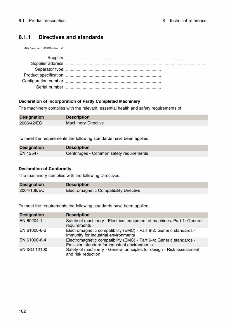
8.1 Product description 8 Technical reference
8.1.1 Directives and standards
Alfa Laval ref. 589764 Rev. 4
Supplier: ......................................................................................................................Supplier address: ......................................................................................................................
Separator type: ................................................................................Product specification: ................................................................................
Configuration number: ................................................................................Serial number: ................................................................................
Declaration of Incorporation of Partly Completed Machinery
The machinery complies with the relevant, essential health and safety requirements of:
Designation Description2006/42/EC Machinery Directive
To meet the requirements the following standards have been applied:
Designation DescriptionEN 12547 Centrifuges - Common safety requirements
Declaration of Conformity
The machinery complies with the following Directives:
Designation Description2004/108/EC Electromagnetic Compatibility Directive
To meet the requirements the following standards have been applied:
Designation DescriptionEN 60204-1 Safety of machinery - Electrical equipment of machines. Part 1: General
requirementsEN 61000-6-2 Electromagnetic compatibility (EMC) - Part 6-2: Generic standards -
Immunity for industrial environmentsEN 61000-6-4 Electromagnetic compatibility (EMC) - Part 6-4: Generic standards -
Emission standard for industrial environmentsEN ISO 12100 Safety of machinery - General principles for design - Risk assessment
and risk reduction
182
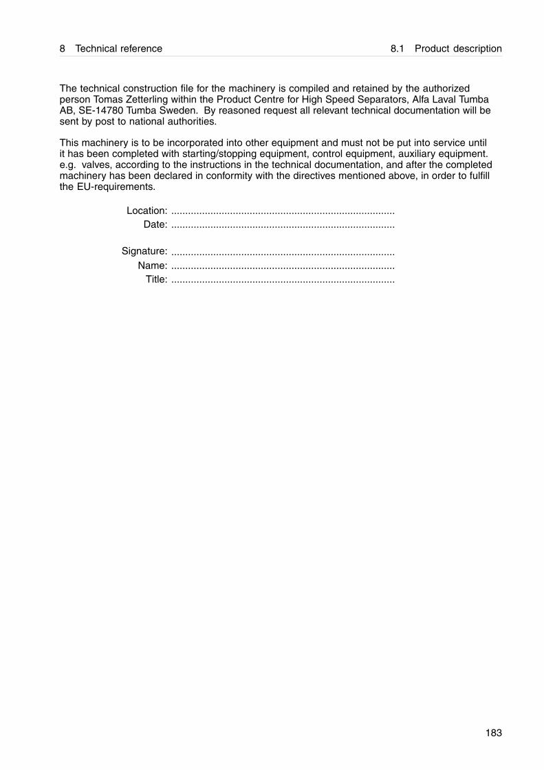
8 Technical reference 8.1 Product description
The technical construction file for the machinery is compiled and retained by the authorizedperson Tomas Zetterling within the Product Centre for High Speed Separators, Alfa Laval TumbaAB, SE-14780 Tumba Sweden. By reasoned request all relevant technical documentation will besent by post to national authorities.
This machinery is to be incorporated into other equipment and must not be put into service untilit has been completed with starting/stopping equipment, control equipment, auxiliary equipment.e.g. valves, according to the instructions in the technical documentation, and after the completedmachinery has been declared in conformity with the directives mentioned above, in order to fulfillthe EU-requirements.
Location: ................................................................................Date: ................................................................................
Signature: ................................................................................Name: ................................................................................
Title: ................................................................................
183

8.2 Technical data 8 Technical reference
8.2 Technical data
Alfa Laval ref. 598392 Rev. 0
Subject Value UnitGeneral technical data:Motor power: 5,5 / 6,4 kW 50Hz/60HzJp reduced to motor 5,12 / 3,53 kgm2 50Hz/60HzGear ratio: 50 Hz 283 / 70Gear ratio: 60 Hz 235 / 70Alarm levels for vibration monitor,connection 752, 1st/2nd:
0,2 / 0,3 mm
Max. bowl inner diameter: 208,5 mm
Min./Max. discharge interval: 2 / 240 minutesMax. density of operating liquid: 1000 kg/m³Max. density feed/sediment: 1100 / 2327 kg/m³Min./Max. feed temperature: 0 / 100 °CMax. running time without flow, bowlempty/filled:
30 / 30 minutes
Bowl material: AL 111 2377-02Operating data:Bowl speed, synchronous: 50 Hz / 60Hz
12129 / 12086 r/min
Motor speed, synchronous: 50 Hz / 60Hz
3000 / 3600 r/min
Maximum allowed speed: 12150 r/minMax. power consumption, start-up: 6,4 kWPower consumption, idling/max.capacity:
2,6 /6,3 kW
Start time min./max.: 60 / 150 secondsStopp time min./max.: 10 / 25 minutesSound power: 9 Bel(A)Sound pressure: 76 dB(A)Max. vibration level, separator in use: 9,1 mm/second (r.m.s)Volume and Capacity data:Maximum hydraulic capacity, bowl: 5,5 m³/hBowl liquid volume: 1,8 litresFixed discharge volume: 1,6 litresSludge volume, efficient/total: 0,25 / 0,64 litresLubricating oil volume: 1,6 litresWeight information:Motor drive weight: 58 kgBowl weight: 37 kgWeight of separator (without motor): 285 kg
184
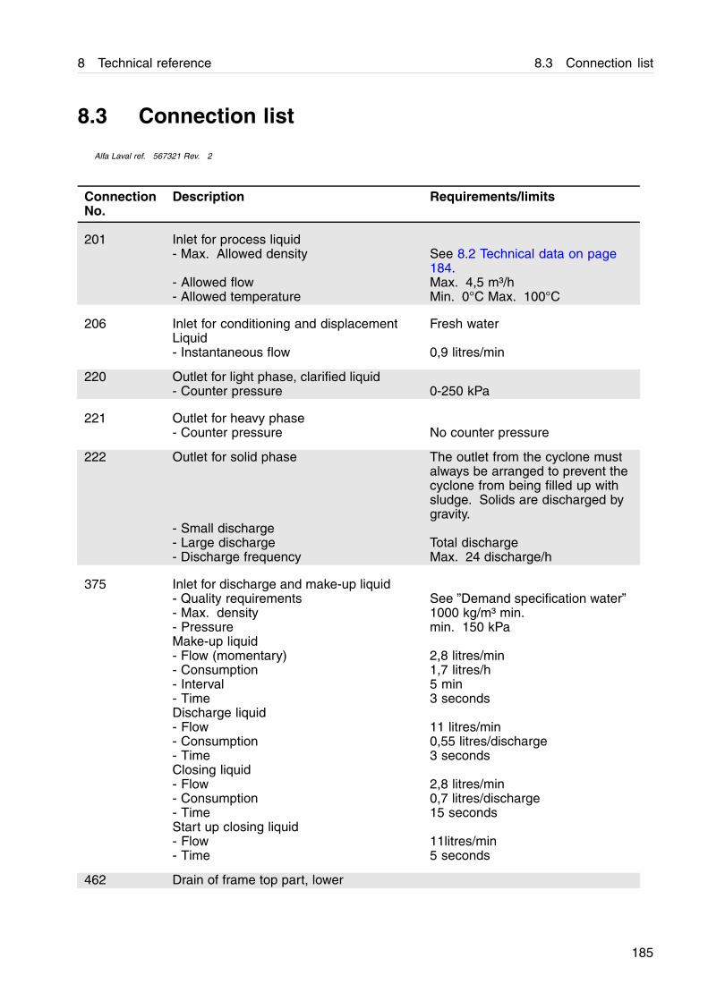
8 Technical reference 8.3 Connection list
8.3 Connection list
Alfa Laval ref. 567321 Rev. 2
Connection Description Requirements/limitsNo.
201 Inlet for process liquid- Max. Allowed density See 8.2 Technical data on page
184.- Allowed flow Max. 4,5 m³/h- Allowed temperature Min. 0°C Max. 100°C
206 Inlet for conditioning and displacementLiquid
Fresh water
- Instantaneous flow 0,9 litres/min
220 Outlet for light phase, clarified liquid- Counter pressure 0-250 kPa
221 Outlet for heavy phase- Counter pressure No counter pressure
222 Outlet for solid phase The outlet from the cyclone mustalways be arranged to prevent thecyclone from being filled up withsludge. Solids are discharged bygravity.
- Small discharge- Large discharge Total discharge- Discharge frequency Max. 24 discharge/h
375 Inlet for discharge and make-up liquid- Quality requirements See ”Demand specification water”- Max. density 1000 kg/m³ min.- Pressure min. 150 kPaMake-up liquid- Flow (momentary) 2,8 litres/min- Consumption 1,7 litres/h- Interval 5 min- Time 3 secondsDischarge liquid- Flow 11 litres/min- Consumption 0,55 litres/discharge- Time 3 secondsClosing liquid- Flow 2,8 litres/min- Consumption 0,7 litres/discharge- Time 15 secondsStart up closing liquid- Flow 11litres/min- Time 5 seconds
462 Drain of frame top part, lower
185
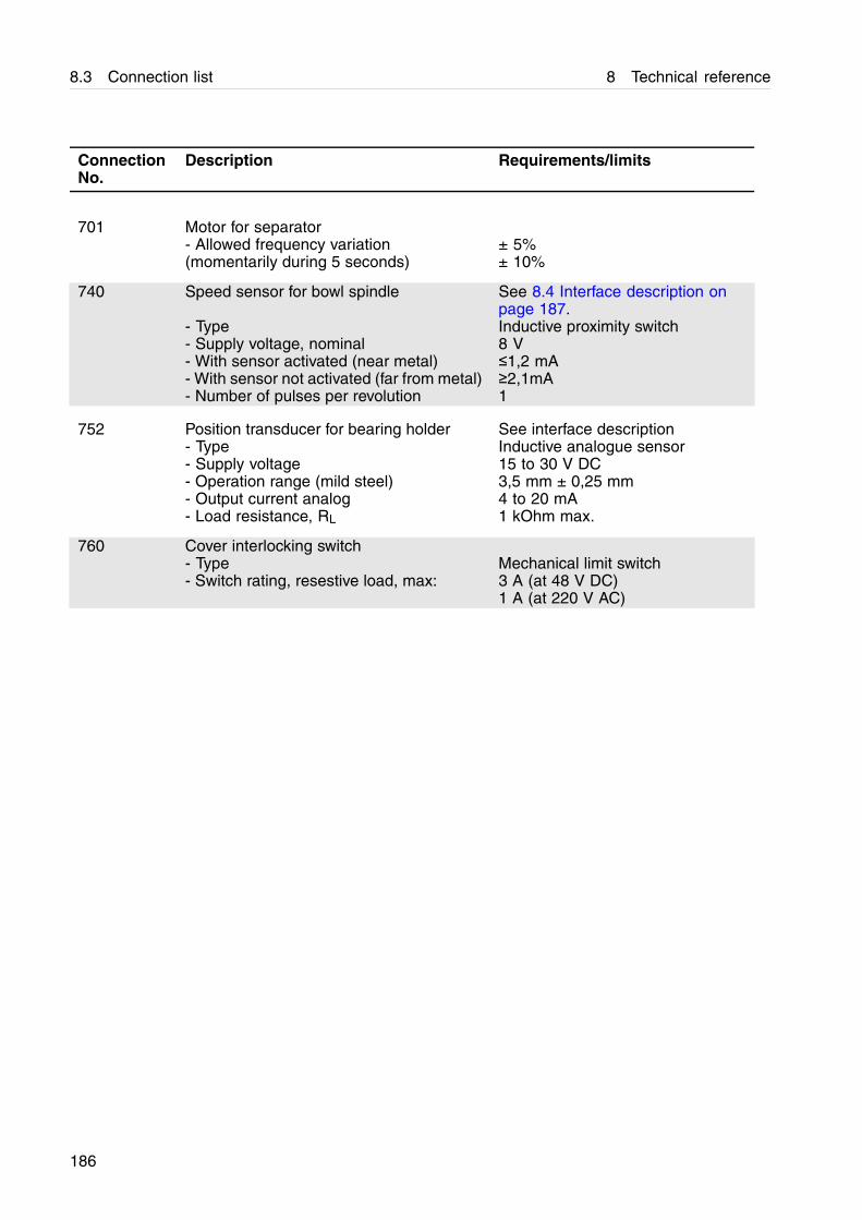
8.3 Connection list 8 Technical reference
Connection Description Requirements/limitsNo.
701 Motor for separator- Allowed frequency variation ± 5%(momentarily during 5 seconds) ± 10%
740 Speed sensor for bowl spindle See 8.4 Interface description onpage 187.
- Type Inductive proximity switch- Supply voltage, nominal 8 V- With sensor activated (near metal) ≤1,2 mA- With sensor not activated (far from metal) ≥2,1mA- Number of pulses per revolution 1
752 Position transducer for bearing holder See interface description- Type Inductive analogue sensor- Supply voltage 15 to 30 V DC- Operation range (mild steel) 3,5 mm ± 0,25 mm- Output current analog 4 to 20 mA- Load resistance, RL 1 kOhm max.
760 Cover interlocking switch- Type Mechanical limit switch- Switch rating, resestive load, max: 3 A (at 48 V DC)
1 A (at 220 V AC)
186
8 Technical reference 8.4 Interface description
8.4 Interface description
Alfa Laval ref. 564834 Rev. 3
8.4.1 Scope
This document gives information, requirements,and recommendations about operationalprocedures and signal processing for safe andreliable operation of the separator. It is intendedto be used for designing auxiliary equipmentand control systems for the separator.
8.4.2 References
This Interface Description is one complementarydocument to the separator. Other suchdocuments that contain necessary informationand are referred to here are:
• Interconnection Diagram
• Connection List
• Technical Data
Standards referred to are:
• EN 418 Safety of machinery - Emergency stopequipment, functional aspects - Principles ofdesign
• EN 1037 Safety of machinery - Prevention ofunexpected start-up
• EN 954-1 Safety of machinery - Safety relatedparts of control systems - Part 1 Generalprinciples for design.
8.4.3 Definitions
For the purpose of this document, the followingdefinitions apply:
• Synchronous speed: The speed the machinewill attain when it is driven by a three phasesquirrel-cage induction motor and there is noslip in the motor and the drive system.
• Full speed: The synchronous speed minusnormal slip.
187
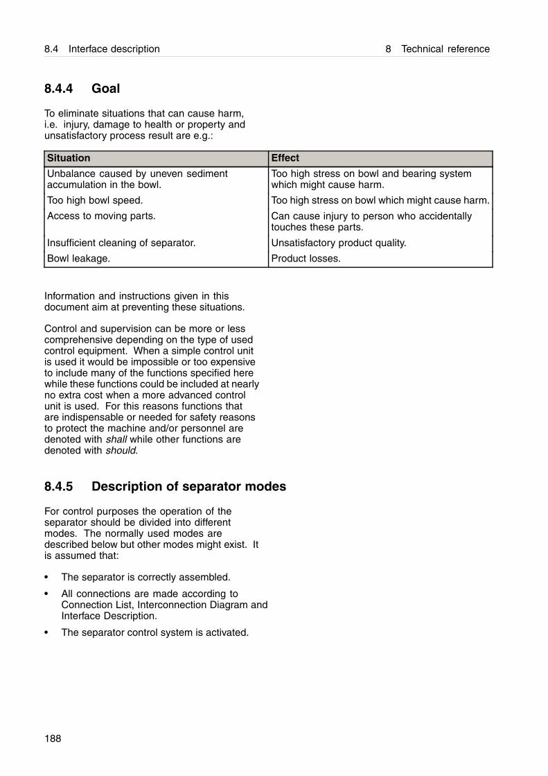
8.4 Interface description 8 Technical reference
8.4.4 Goal
To eliminate situations that can cause harm,i.e. injury, damage to health or property andunsatisfactory process result are e.g.:
Situation Effect
Unbalance caused by uneven sedimentaccumulation in the bowl.
Too high stress on bowl and bearing systemwhich might cause harm.
Too high bowl speed. Too high stress on bowl which might cause harm.
Access to moving parts. Can cause injury to person who accidentallytouches these parts.
Insufficient cleaning of separator. Unsatisfactory product quality.
Bowl leakage. Product losses.
Information and instructions given in thisdocument aim at preventing these situations.
Control and supervision can be more or lesscomprehensive depending on the type of usedcontrol equipment. When a simple control unitis used it would be impossible or too expensiveto include many of the functions specified herewhile these functions could be included at nearlyno extra cost when a more advanced controlunit is used. For this reasons functions thatare indispensable or needed for safety reasonsto protect the machine and/or personnel aredenoted with shall while other functions aredenoted with should.
8.4.5 Description of separator modes
For control purposes the operation of theseparator should be divided into differentmodes. The normally used modes aredescribed below but other modes might exist. Itis assumed that:
• The separator is correctly assembled.
• All connections are made according toConnection List, Interconnection Diagram andInterface Description.
• The separator control system is activated.
188
8 Technical reference 8.4 Interface description
If above conditions are not fulfilled the separatorwill be in SERVICE mode.
Stand still means:
• The power to the separator motor is off
• The bowl is not rotating.
Starting means:
• The power to the separator motor is on.
• The bowl is rotating and accelerating.
Running means:
• The power to the separator motor is on.
• The bowl is rotating at full speed.
• RUNNING is a collective denomination for anumber of sub modes which e.g. can be:
- STAND BY: Separator is in a waiting mode andnot producing.
- PRODUCTION: Separator is fed with productand producing.
- CLEANING: Separator is fed with cleaningliquids with the intention to clean the separator.
Stopping means:
• The power to the separator motor is off.
• The bowl is rotating and decelerating.
• STOPPING is a collective denomination for anumber of sub modes which e.g. can be:
- NORMAL STOP: A manually or automaticallyinitiated stop.
- SAFETY STOP: An automatically initiated stopat too high vibrations.
- EMERGENCY STOP: A manually initiated stopat emergency situations. This stop will be ineffect until it is manually reset.
189
8.4 Interface description 8 Technical reference
8.4.6 Remote start
This machine may be started from a remotelocation under the following conditions;
• First start after any kind of service or manualcleaning must be supervised locally in order toensure that no mistakes has been made duringassembly.
• The unbalance sensor is mandatory for remotestart.
• The installation must include equipment toprevent unintentional start-up from remotelocation when the machine is disassembled.
• The installation must include equipment toprevent unintentional start of process flowfrom remote location when the machine is notproperly connected to the piping.
8.4.7 Handling of connection interfaces
Electrical connections
701 Separator motor.
The separator is equipped with a 3-phase DOL- (direct on line) started motor. The separatorcan also be started by a Y/D starter, but thenthe time in Y-position must be maximized to 5seconds.
There shall be an emergency stop circuitdesigned according to EN 418 and a powerisolation device according to EN 1037.
There shall be a start button close to theseparator that shall be used for first start afterassembly of the separator.
There should be a counter to count number ofrunning hours.
There should be a current transformer to givean analogue signal to the control unit about themotor current.
190

8 Technical reference 8.4 Interface description
740 Speed sensor
A proximity sensor of inductive type accordingto Namur standard is giving a number of pulsesper revolution of the bowl (see Connection List).
Signal processing in STARTING:
• The separator should be stopped automaticallyaccording to NORMAL STOP procedureand an alarm should be given when theaccumulated time for acceleration is longerthan the maximum time specified in TechnicalData. An abnormal start time indicates somemalfunction of the separator equipment andshould be investigated.
• If the speed exceeds “Bowl speed, synchronous”in Technical Data with more than 5% theseparator shall be stopped automatically byNORMAL STOP and a high speed alarm shallbe given.
• The speed monitoring system shall be checkedcontinuously (e.g. by checking that pulsesare coming). In case of failure indication theseparator shall be stopped automatically byNORMAL STOP with a timer controlled stopsequence and an alarm for speed monitoringsystem failure shall be given.
• The acceleration should be supervised toensure that a certain speed (e.g. 250 r/min.)has been reached within a certain time (e.g. 30seconds).
191
8.4 Interface description 8 Technical reference
Signal processing in RUNNING:
• If the speed exceeds “Bowl speed, synchronous”in Technical Data with more than 5% for aperiod longer than 1 minute or momentarilyduring maximum 5 seconds more than 10%the separator shall be stopped automatically byNORMAL STOP and a high speed alarm shallbe given.
• If the speed falls more than 10% below thesynchronous speed for a period longer than 1minute or 15% during more than 5 seconds alow speed alarm should be given. Low speedindicates some malfunction of the separatorequipment and shall be investigated.
• The speed monitoring system shall be checkedcontinuously (e.g. by checking that pulses arecoming). In case of a failure indication an alarmfor speed monitoring system failure shall begiven. If there is a risk of too high speed theseparator shall be stopped by NORMAL STOP.
• The speed drop during DISCHARGE. comparedto the measured speed immediately before,should be between 3-8% which will indicate aproper discharge.
Signal processing in STOPPING:
• STAND STILL shall be indicated when no pulsesare detected within 30 seconds.
• Stopping the separator when alarm for speedmonitoring system failure is active, shall causea timer controlled stop. (See “Stop time” in 8.2Technical data on page 184.)
752 Unbalance sensor (optional).
For indication of any abnormal unbalanceand to be able to perform appropriatecountermeasures, the separator has beenequipped with an inductive analogue sensormonitoring the radial position of the Top bearingseat on the separator frame. The signal fromthe sensor shall be monitored and two alarmlevels according to the vibration alarm levels inTechnical data on page 184 should be set.
The vibration level shall be high for 3 seconds togenerate an alarm. The first level is only used togenerate an alarm while the second level shallstop the machine.
192
8 Technical reference 8.4 Interface description
The vibration monitor shall include self checkfunction to be performed at least at initiation ofSTARTING.
If vibrations exceed the second alarm level theseparator shall be stopped the quickest waypossible and it shall not been restarted until thereasons for the unbalance have been found andmeasures to remove them have been taken.
Signal processing in STARTING:
If vibrations exceed the second alarm level theseparator shall be stopped automatically bySAFETY STOP.
If the self check system triggers, an alarm shallbe given and an automatic stop by NORMALSTOP shall be initiated.
Signal processing in RUNNING:
• If vibrations exceed the first alarm level an alarmshould be given. Vibrations of this magnitudewill reduce the expected life time of the bearingsand should therefore be eliminated.
• If vibrations exceed the second alarm level theseparator shall be stopped automatically bySAFETY STOP.
• If the self check system triggers, an alarm shallbe given.
Signal processing in STOPPING:
• If the self check system triggers, an alarm shallbe given.
Signal processing in NORMAL STOP:
• If vibrations exceed the second level the systemshall turn over automatically to SAFETY STOP.
760 Cover interlocking switch (optional)
The separator is equipped with a interlockingswitch to detect if the cover is mounted.
Signal processing in STAND STILL:
• The circuit is closed when the cover of theseparator is mounted.
• The interlocking switch should be connectedin such a way that starting of the motor isprevented when the separator cover is notmounted.
193
8.4 Interface description 8 Technical reference
Signal processing in STARTING, RUNNING andCLEANING:
• If the circuit is broken the separator shouldbe stopped automatically by NORMAL STOP.This is to minimise the risk of having access tomoving parts.
Fluid connections
Complementary information is given in thedocument Connection List.
201 Inlet
Processing in STAND STILL:
• Shall be closed.
Processing in STARTING:
• Should be closed. Bowl will be open and emptyor closed and filled depending on if start is donefrom STAND STILL or STOPPING.
Processing in RUNNING:
• Could be closed or open.
Processing in CLEANING:
• A sequence of cleaning liquids should be fedto the separator. The flow rate should be ashigh as possible and preferably not less thanthe production flow rate.
Processing in NORMAL STOP or EMERGENCYSTOP:
• Could be closed or open but the bowl should befilled unless the stop is initiated in STARTING.
Processing in SAFETY STOP:
• Could be closed or open but the bowl shall befilled unless the stop is initiated in STARTING.
206 Inlet for conditioning and displacementliquid
• According to process
220, 221 and 222 Outlets
Processing in STAND STILL:
• Could be closed or open.
Processing in other modes:
• Shall be open.
194
8 Technical reference 8.4 Interface description
375 Inlet for discharge and make-up liquid
Processing in all modes:
• It is recommended to supervise the supplypressure. If pressure is too low (see ConnectionList), start should be interlocked and if ithappens in PRODUCTION or CLEANING turnover to STAND BY should take place.
Signal processing in STARTING:
• Below 85 % of synchronous bowl speed nowater supply may be made.
• When coming from PRODUCTION a dischargeshall be initiated to remove sediment from bowlto avoid problems due to solidification, seeConnection List.
Signal processing in PRODUCTION:
• Automatic discharges shall be initiated by timeror ALCAP system.
Signal processing in CLEANING:
• Automatic discharges shall be initiated by timeror CIP-control system.
Signal processing in NORMAL STOP:
• Discharges should not be made.
Signal processing in SAFETY STOP andEMERGENCY STOP:
• Discharges should not be made.
195
8.5 Demand specification water 8 Technical reference
8.5 Demand specification water
Alfa Laval ref. 574487 Rev. 2
Operating water is used in the separator forseveral different functions: e.g. to operate thedischarge mechanism, to lubricate and coolmechanical seals.
Poor quality of the operating water may causeerosion, corrosion and/or operating problem inthe separator and must therefore be treated tomeet certain demands.
NOTE
Alfa Laval accepts no liability for consequencesarising from unsatisfactorily purified operating watersupplied by the customer.
The following conditions must be fulfilled:
1. Turbidity free water, solids content <0.001% byvolume.Deposits must not be allowed to form in certainareas in the separator.
2. A maximum particle size of 50 µm.
3. A total hardness of <180 mg CaCO3 per litre,which corresponds to 10°dH or 12.5°E.Hard water may with time form deposits inthe operating mechanism. The precipitationrate is accelerated with increased operatingtemperature and low discharge frequency.These effects become more severe as thehardness of the water increase.
4. A chloride content of maximum 100 ppm NaCl(equivalent to 60 mg Cl/l).A chloride concentration above 60 mg/l is notrecommended.Chloride ions contribute to corrosion on theseparator surface in contact with the operatingwater, including the spindle. Corrosion isa process that is accelerated by increasedseparating temperature, low pH, and highchloride ion concentration.
5. 6.5 < pH < 9Increased acidity (lower pH) increases the riskfor corrosion; this is accelerated by increasedtemperature and high chloride ion content.
6. A bicarbonate content (HCO3) of minimum70 mg HCO3 per litre, which corresponds to3.2°dKH.
196
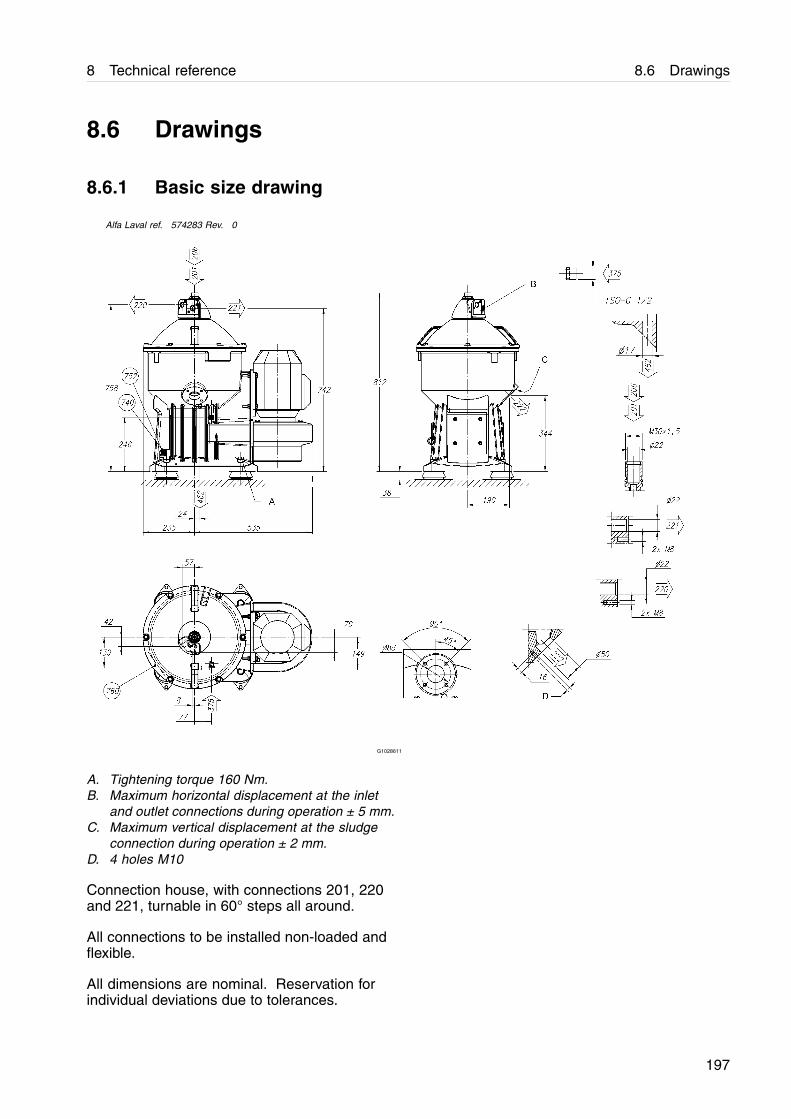
8 Technical reference 8.6 Drawings
8.6 Drawings
8.6.1 Basic size drawing
Alfa Laval ref. 574283 Rev. 0
G1028611
A. Tightening torque 160 Nm.B. Maximum horizontal displacement at the inlet
and outlet connections during operation ± 5 mm.C. Maximum vertical displacement at the sludge
connection during operation ± 2 mm.D. 4 holes M10
Connection house, with connections 201, 220and 221, turnable in 60° steps all around.
All connections to be installed non-loaded andflexible.
All dimensions are nominal. Reservation forindividual deviations due to tolerances.
197
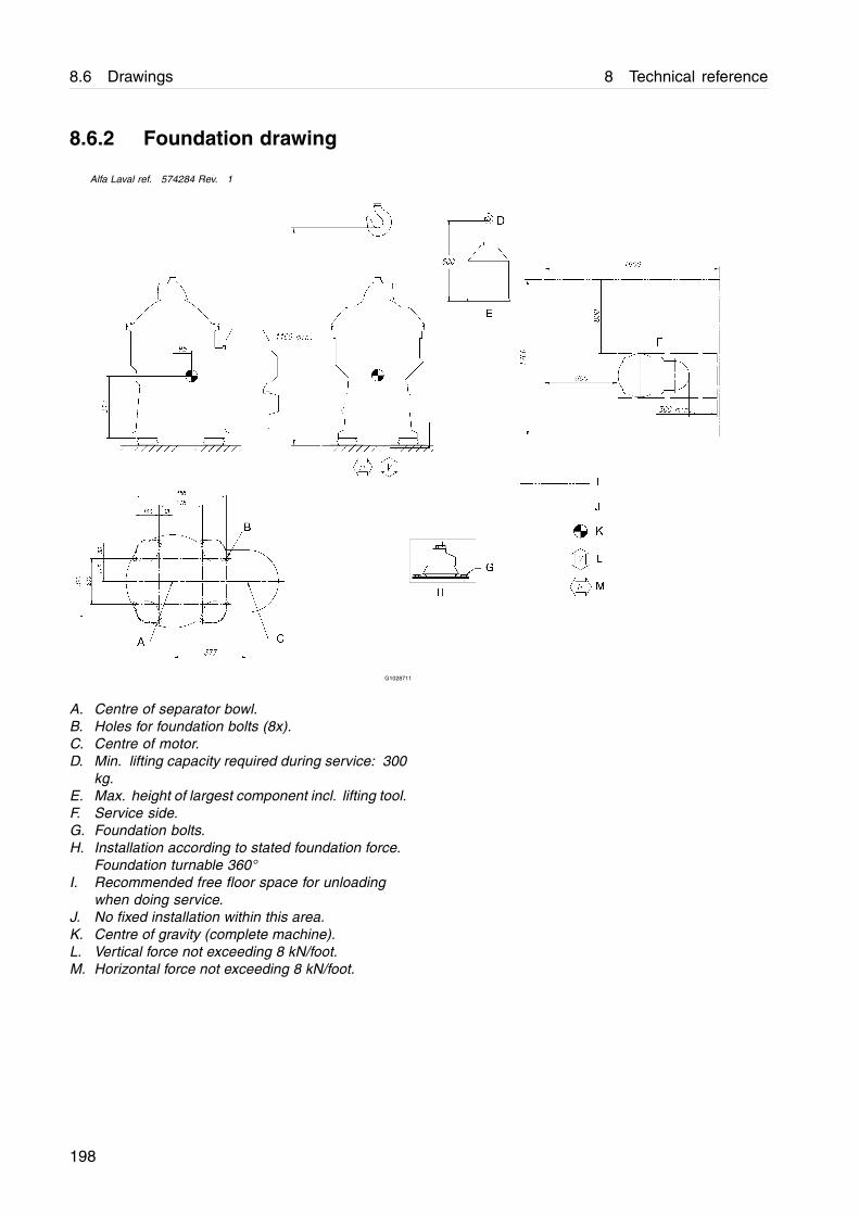
8.6 Drawings 8 Technical reference
8.6.2 Foundation drawing
Alfa Laval ref. 574284 Rev. 1
G1028711
A. Centre of separator bowl.B. Holes for foundation bolts (8x).C. Centre of motor.D. Min. lifting capacity required during service: 300
kg.E. Max. height of largest component incl. lifting tool.F. Service side.G. Foundation bolts.H. Installation according to stated foundation force.
Foundation turnable 360°I. Recommended free floor space for unloading
when doing service.J. No fixed installation within this area.K. Centre of gravity (complete machine).L. Vertical force not exceeding 8 kN/foot.M. Horizontal force not exceeding 8 kN/foot.
198
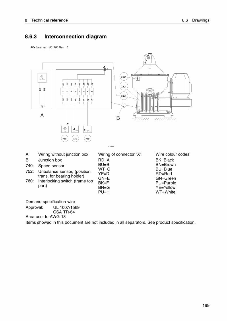
8 Technical reference 8.6 Drawings
8.6.3 Interconnection diagram
Alfa Laval ref. 561786 Rev. 5
N
752740
J
1 2 3 4 5 6 7 8
BU
BN
BU
BN
BK
GN
RD
BK
RD
BU
GN
YW
WT
BK
BN
PU
X
S
760
760
752
740
1
BU
BN
DC
- +
A B
G1019311
A: Wiring without junction box Wiring of connector “X”: Wire colour codes:B: Junction box740: Speed sensor752: Unbalance sensor, (position
trans. for bearing holder)760: Interlocking switch (frame top
part)
RD=ABU=BWT=CYE=DGN=EBK=FBN=GPU=H
BK=BlackBN=BrownBU=BlueRD=RedGN=GreenPU=PurpleYE=YellowWT=White
Demand specification wireApproval: UL 1007/1569
CSA TR-64Area acc. to AWG 18Items showed in this document are not included in all separators. See product specification.
199

8.6 Drawings 8 Technical reference
8.6.4 PX sealing diagram
Alfa Laval ref. 566570 Rev. 0
G08697d1
A. No sealingB. Operational envelopeC. Non physical
Separator bowl speed: 12129 r/min
Separator bowl number: 564214-01
References density for Feed: 1100 kg/m3
References density for Wet solids: 2327 kg/m3
NOTE
Max. allowed operating liquid density: 1000 kg/m3
200

8 Technical reference 8.6 Drawings
8.6.5 Electric motor
Alfa Laval ref. 9011208 Rev. 4
G10288g1
Manufacturer: ABB Motors Type of mounting Degree ofprotection
Type: M3AA 112 MB2Poles: 2
G0541421
IM 2111 IP 55
Bearings: D-end 6306-2Z/C3N-end 6206-2Z/C3
NOTE
For complete information about motor variants, pleasecontact your Alfa Laval representative.
201

8.6 Drawings 8 Technical reference
9 Installation
9.1 Introduction
The installation instructions are specifications,which are compulsory requirements.
Any specific requirements from classificationsocieties or other local authorities must befollowed.
NOTE
If the specifications are not followed, Alfa Laval cannot be held responsible for any malfunctions relatedto the installation.
203
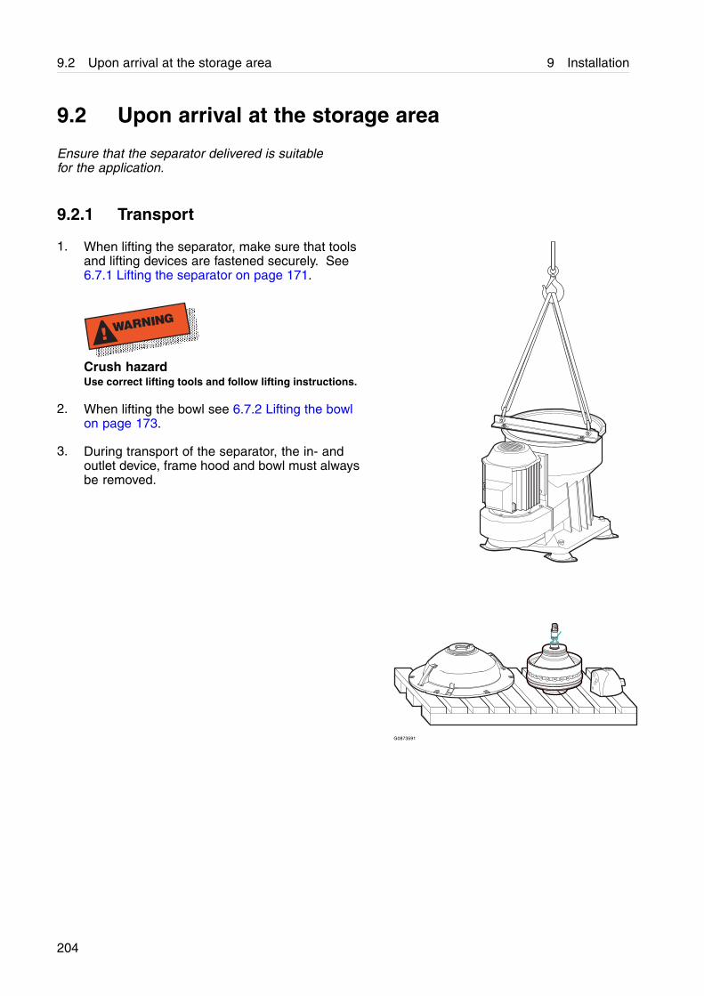
9.2 Upon arrival at the storage area 9 Installation
9.2 Upon arrival at the storage area
Ensure that the separator delivered is suitablefor the application.
9.2.1 Transport
1. When lifting the separator, make sure that toolsand lifting devices are fastened securely. See6.7.1 Lifting the separator on page 171.
! WARNING
Crush hazardUse correct lifting tools and follow lifting instructions.
2. When lifting the bowl see 6.7.2 Lifting the bowlon page 173.
3. During transport of the separator, the in- andoutlet device, frame hood and bowl must alwaysbe removed.
G0873591
204
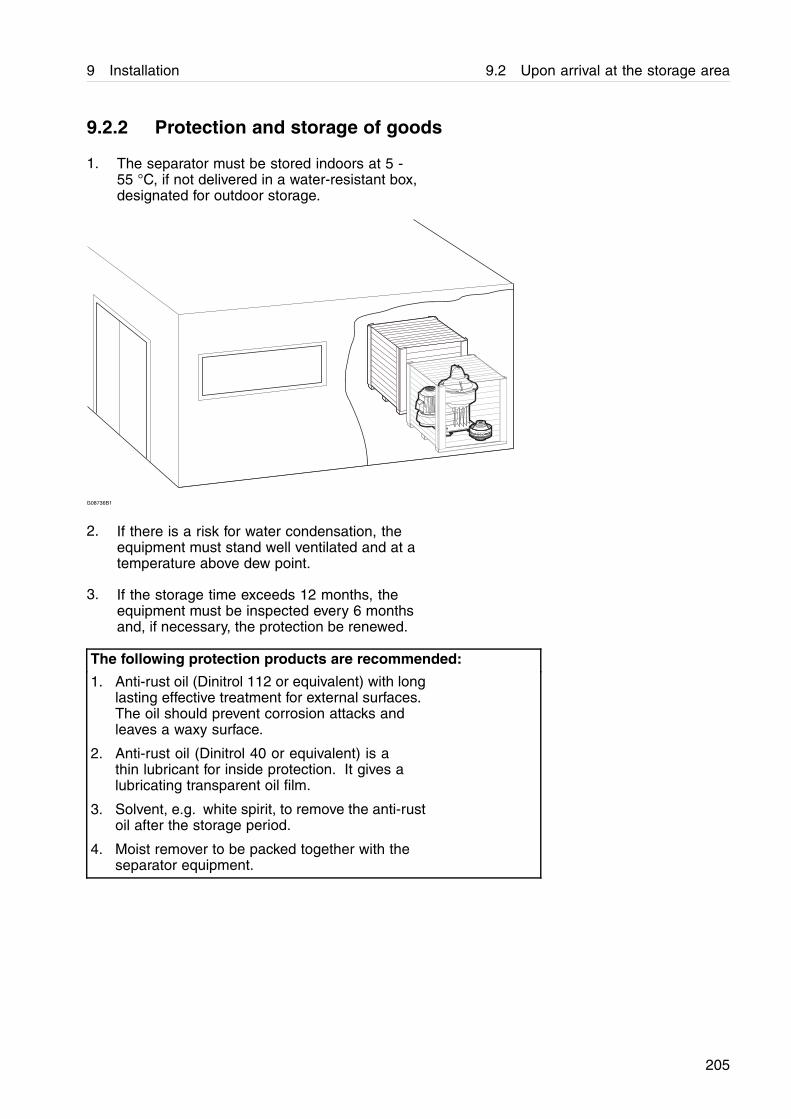
9 Installation 9.2 Upon arrival at the storage area
9.2.2 Protection and storage of goods
1. The separator must be stored indoors at 5 -55 °C, if not delivered in a water-resistant box,designated for outdoor storage.
G08736B1
2. If there is a risk for water condensation, theequipment must stand well ventilated and at atemperature above dew point.
3. If the storage time exceeds 12 months, theequipment must be inspected every 6 monthsand, if necessary, the protection be renewed.
The following protection products are recommended:
1. Anti-rust oil (Dinitrol 112 or equivalent) with longlasting effective treatment for external surfaces.The oil should prevent corrosion attacks andleaves a waxy surface.
2. Anti-rust oil (Dinitrol 40 or equivalent) is athin lubricant for inside protection. It gives alubricating transparent oil film.
3. Solvent, e.g. white spirit, to remove the anti-rustoil after the storage period.
4. Moist remover to be packed together with theseparator equipment.
205
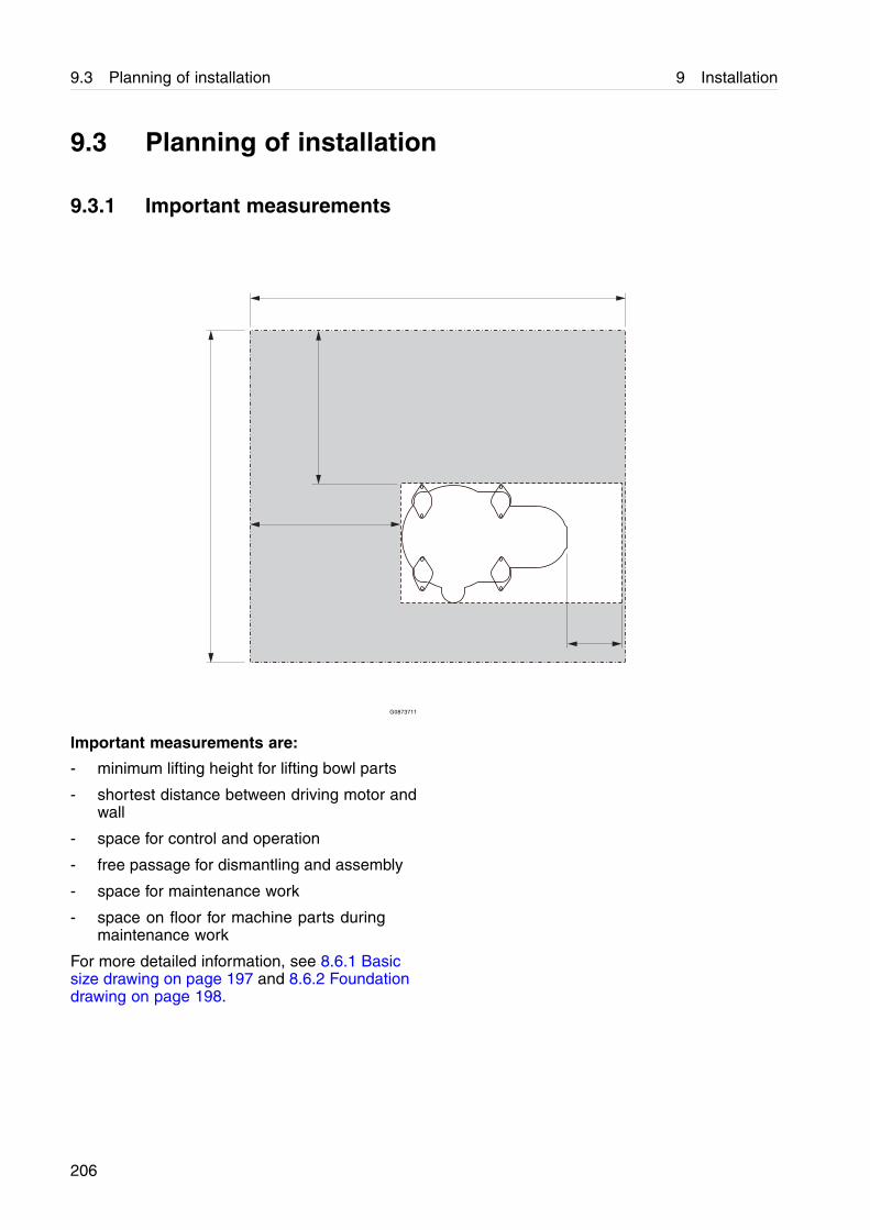
9.3 Planning of installation 9 Installation
9.3 Planning of installation
9.3.1 Important measurements
G0873711
Important measurements are:
- minimum lifting height for lifting bowl parts
- shortest distance between driving motor andwall
- space for control and operation
- free passage for dismantling and assembly
- space for maintenance work
- space on floor for machine parts duringmaintenance work
For more detailed information, see 8.6.1 Basicsize drawing on page 197 and 8.6.2 Foundationdrawing on page 198.
206
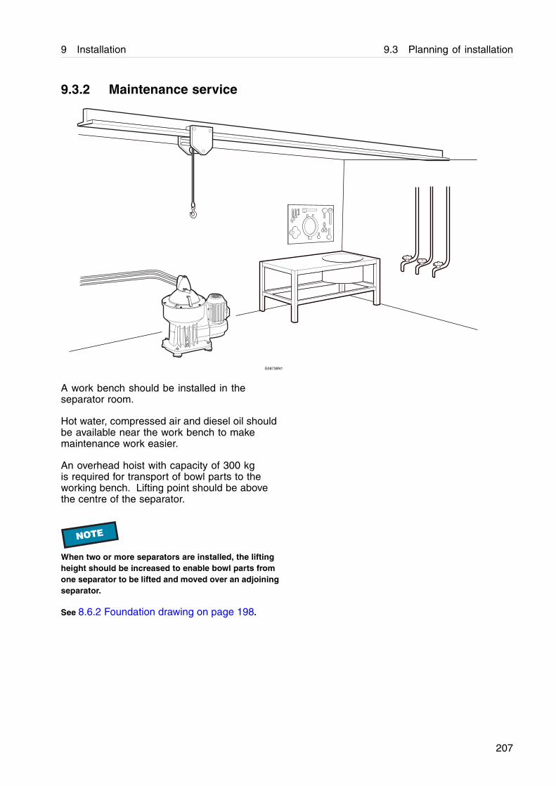
9 Installation 9.3 Planning of installation
9.3.2 Maintenance service
G08738N1
A work bench should be installed in theseparator room.
Hot water, compressed air and diesel oil shouldbe available near the work bench to makemaintenance work easier.
An overhead hoist with capacity of 300 kgis required for transport of bowl parts to theworking bench. Lifting point should be abovethe centre of the separator.
NOTE
When two or more separators are installed, the liftingheight should be increased to enable bowl parts fromone separator to be lifted and moved over an adjoiningseparator.
See 8.6.2 Foundation drawing on page 198.
207
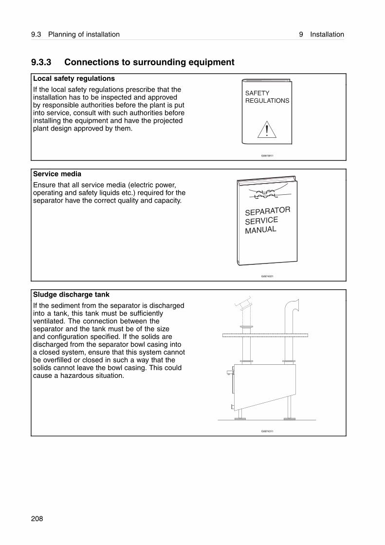
9.3 Planning of installation 9 Installation
9.3.3 Connections to surrounding equipment
Local safety regulations
If the local safety regulations prescribe that theinstallation has to be inspected and approvedby responsible authorities before the plant is putinto service, consult with such authorities beforeinstalling the equipment and have the projectedplant design approved by them.
G0873911
Service media
Ensure that all service media (electric power,operating and safety liquids etc.) required for theseparator have the correct quality and capacity.
G0874021
Sludge discharge tank
If the sediment from the separator is dischargedinto a tank, this tank must be sufficientlyventilated. The connection between theseparator and the tank must be of the sizeand configuration specified. If the solids aredischarged from the separator bowl casing intoa closed system, ensure that this system cannotbe overfilled or closed in such a way that thesolids cannot leave the bowl casing. This couldcause a hazardous situation.
G0874311
208
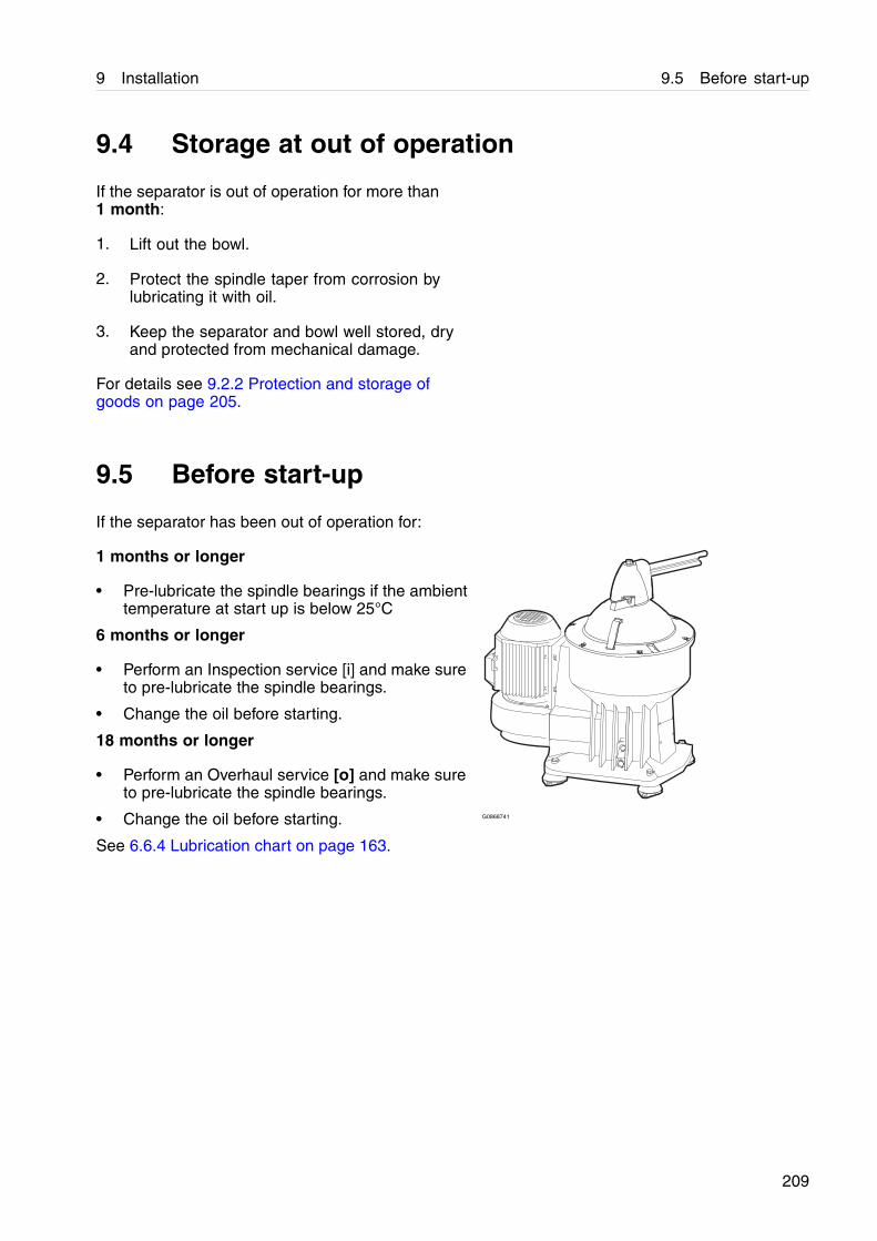
9 Installation 9.5 Before start-up
9.4 Storage at out of operation
If the separator is out of operation for more than1 month:
1. Lift out the bowl.
2. Protect the spindle taper from corrosion bylubricating it with oil.
3. Keep the separator and bowl well stored, dryand protected from mechanical damage.
For details see 9.2.2 Protection and storage ofgoods on page 205.
9.5 Before start-up
If the separator has been out of operation for:
1 months or longer
• Pre-lubricate the spindle bearings if the ambienttemperature at start up is below 25°C
6 months or longer
• Perform an Inspection service [i] and make sureto pre-lubricate the spindle bearings.
• Change the oil before starting.
18 months or longer
• Perform an Overhaul service [o] and make sureto pre-lubricate the spindle bearings.
• Change the oil before starting.
See 6.6.4 Lubrication chart on page 163.
G0868741
209