Embed Size (px)
Citation preview
Sentinel VoLTE Architecture
TAS-022-Issue 2.6.0-Release 1
August 2018
Sentinel VoLTE Architecture (V2.6.0)
Notices
Copyright © 2017 Metaswitch Networks. All rights reserved.
This manual is issued on a controlled basis to a specific person on the understanding that no part of the
Metaswitch Networks product code or documentation (including this manual) will be copied or distributed
without prior agreement in writing from Metaswitch Networks.
Metaswitch Networks reserves the right to, without notice, modify or revise all or part of this document
and/or change product features or specifications and shall not be responsible for any loss, cost, or
damage, including consequential damage, caused by reliance on these materials.
Metaswitch and the Metaswitch logo are trademarks of Metaswitch Networks. Other brands and products
referenced herein are the trademarks or registered trademarks of their respective holders.
2
Sentinel VoLTE Architecture (V2.6.0)
Contents
1 Sentinel VoLTE Architecture...................................................................................... 7
1.1 Intended audience....................................................................................................................... 7
1.2 Contents.......................................................................................................................................7
2 Overview.......................................................................................................................8
3 Product Overview........................................................................................................ 9
3.1 Open and fully-featured............................................................................................................... 9
3.2 MMTEL-AS and SCC-AS on the Rhino TAS............................................................................... 9
4 MMTel Services..........................................................................................................11
5 GSMA MMTel Supplementary Services................................................................... 12
5.1 Originating Identification Presentation/Restriction (OIP/OIR) (3GPP TS 24.607)......................12
5.2 Terminating Identification Presentation/Restriction (TIP/TIR) (3GPP TS 24.608)..................... 12
5.3 Communication Diversion (CDIV) (3GPP TS 24.604)................................................................13
5.4 Communication Hold (HOLD) (3GPP TS 24.610)......................................................................13
5.5 Communication Barring (CB) (3GPP 24.611)............................................................................ 13
5.6 Operator Determined Barring (ODB) (3GPP TS 24.315 and TS 24.041).................................. 14
5.7 Explicit Call Transfer (ECT) (3GPP TS24.629)..........................................................................17
5.8 Communication Waiting (CW) (3GPP TS24.615)...................................................................... 17
5.9 Ad-hoc multi-party conference (CONF) (3GPP 24.605)............................................................ 17
5.10 Anonymous Call Rejection (ACR) (3GPP TS24.611).............................................................. 18
5.10.1 XCAP interface (Ut)....................................................................................................18
6 Explicit Communication Transfer............................................................................ 19
6.1 Communication Transfer Modes................................................................................................19
6.2 Example Explicit Communication Transfer Call Flows...............................................................19
6.2.1 Blind ECT..................................................................................................................... 20
6.2.2 Consultive ECT............................................................................................................ 21
6.3 Instance models inside VoLTE.................................................................................................. 21
6.4 Charging.................................................................................................................................... 24
6.4.1 Out of Scope................................................................................................................ 24
7 Flexible Alerting.........................................................................................................25
7.1 What is Flexible Alerting............................................................................................................ 25
7.2 Group Members......................................................................................................................... 25
7.3 Alerting type............................................................................................................................... 25
3
Sentinel VoLTE Architecture (V2.6.0)
7.4 Flexible Alerting Features.......................................................................................................... 26
7.5 Flexible Alerting Mode Examples Call Flow...............................................................................26
7.5.1 Parallel Alerting for group type of multiple-users......................................................... 26
7.5.2 Parallel Alerting for group type of single-user.............................................................. 27
7.5.3 Sequential Alerting for group of type multiple-users.................................................... 28
7.5.4 Sequential Alerting for group type of single-user......................................................... 29
8 Session Transfer to Own Device..............................................................................31
8.1 Service description.....................................................................................................................31
8.2 Pre requisites............................................................................................................................. 31
8.3 Basic flow...................................................................................................................................31
8.4 Features.....................................................................................................................................32
9 Charging..................................................................................................................... 34
9.1 Multiple OCS support.................................................................................................................34
9.2 Re-authorization.........................................................................................................................35
9.3 CDR generation......................................................................................................................... 35
9.4 Use of a Prepaid SCP via CAP..................................................................................................35
10 SCC-AS Services..................................................................................................... 36
10.1 IMS Centralised Services (ICS) support.................................................................................. 36
10.2 Terminating Access Domain Selection (T-ADS)...................................................................... 37
10.2.1 Computing the Circuit Switched Routing Number......................................................38
10.2.2 The OC-Terminating-Domain Header........................................................................ 38
10.2.3 Extensibility................................................................................................................ 38
10.3 Service Continuity and Access Transfer.................................................................................. 39
11 Architecture Overview.............................................................................................42
11.1 Major components................................................................................................................... 42
11.1.1 JSLEE services.......................................................................................................... 43
11.2 Sentinel VoLTE in an LTE network.......................................................................................... 43
11.3 B2BUA architecture................................................................................................................. 43
11.3.1 iFC Triggering Chaining and the SCC and MMTEL................................................... 44
11.3.2 Co-location using the Rhino SIS................................................................................ 44
11.4 Subscriber Data Storage..........................................................................................................45
11.5 Supplementary services database...........................................................................................45
11.6 Media resource function...........................................................................................................45
11.7 Cloud and virtualisation............................................................................................................46
12 Cloud and Virtualisation......................................................................................... 47
4
Sentinel VoLTE Architecture (V2.6.0)
13 XCAP Support.......................................................................................................... 48
13.1 XCAP architecture within the IMS............................................................................................48
13.2 Sentinel VoLTE and XCAP...................................................................................................... 48
13.2.1 HTTP URIs and XCAP............................................................................................... 49
13.3 Integration with Rhino Element Manager and Sentinel............................................................49
13.3.1 Integrated components.............................................................................................. 49
13.3.2 Diameter Sh stacks and Rhino clusters..................................................................... 50
14 XCAP Query Examples............................................................................................51
14.1 Get simservs document........................................................................................................... 51
14.2 Get active state of OIP supplementary service........................................................................52
14.3 Get default-behaviour of OIR supplementary service.............................................................. 52
14.4 Enable OIP supplementary service..........................................................................................53
14.5 Disable OIP supplementary service.........................................................................................53
14.6 Set OIR default-behaviour to presentation-restricted...............................................................54
14.7 Set OIR default-behaviour to presentation-not-restricted........................................................ 55
15 Instance Architecture for Sentinel VoLTE.............................................................56
15.1 iFC triggering chaining and the SCC and MMTEL...................................................................56
15.2 Co-location using the Rhino SIS.............................................................................................. 57
16 Third Party Registrar Architecture.........................................................................58
17 Online Charging Support........................................................................................ 60
17.1 Charging instance model......................................................................................................... 60
17.2 Charging within the instance model......................................................................................... 61
17.3 SDP and charging....................................................................................................................62
17.4 Charging and Sessions Terminating in WiFi Networks............................................................63
17.5 Population of AVPs on the Diameter Ro interface................................................................... 64
18 Sh Cache RA Architecture...................................................................................... 65
18.1 Basic components....................................................................................................................65
18.1.1 Basic cache RA function............................................................................................ 66
18.1.2 Cache instances and types........................................................................................ 66
18.1.3 Cache configuration................................................................................................... 67
18.2 Diameter and Diameter Sh use................................................................................................67
18.2.1 Synchronous and asynchronous lookups.................................................................. 67
18.3 The Sh cache RA in VoLTE..................................................................................................... 68
18.4 Subscriber data lookup............................................................................................................ 68
18.4.1 Non-transparent data use.......................................................................................... 68
5
Sentinel VoLTE Architecture (V2.6.0)
18.4.2 Multi-tenancy within the cache................................................................................... 69
19 CAMEL and SIP support for SCC........................................................................... 70
20 Access to the HSS and HLR................................................................................... 72
20.1 HSS access............................................................................................................................. 72
20.2 HLR access..............................................................................................................................72
20.3 Supplementary Service Data................................................................................................... 73
21 Supplementary Service Data Access.....................................................................74
21.1 Supplementary Service Data stored in the HSS...................................................................... 74
21.2 Supplementary Service Data stored in the HLR...................................................................... 74
22 SDP conflict management...................................................................................... 75
22.1 SDP conflict management overview........................................................................................ 75
22.2 Access transfer example..........................................................................................................76
22.3 SDP conflict types....................................................................................................................78
22.3.1 Session ID and version.............................................................................................. 78
22.3.2 Media descriptions removed...................................................................................... 79
22.3.3 Media descriptions added.......................................................................................... 79
22.3.4 Reusing a media description that was previously set to zero.....................................80
22.3.5 Payload type conflicts................................................................................................ 81
22.3.6 Conflict types not supported.......................................................................................82
22.4 Using SDP conflict management in a feature.......................................................................... 82
22.5 SDP encoding issues and workarounds.................................................................................. 82
22.5.1 Number of ports in media lines.................................................................................. 82
23 Session Tracking..................................................................................................... 84
23.1 Tracked Session Information................................................................................................... 84
23.2 Use of Cassandra Database....................................................................................................85
23.2.1 Row Time-to-Live....................................................................................................... 86
23.2.2 Consistency Level...................................................................................................... 86
23.2.3 Cassandra Schema....................................................................................................87
23.3 Minimising the impact of Database issues on Session processing..........................................87
23.4 Session Tracking Features...................................................................................................... 88
24 Shared ATU-STI....................................................................................................... 89
24.1 Co-ordinating Access Transfer................................................................................................ 89
24.2 A simple co-ordination example...............................................................................................90
24.3 A more complex co-ordination example...................................................................................91
6
Sentinel VoLTE Architecture (V2.6.0)
1 Sentinel VoLTE Architecture
1.1 Intended audience
This document is intended for:
• network architects and engineers selecting and deploying VoLTE infrastructures
• solution architects defining solutions in the VoLTE space
• software developers using the Sentinel VoLTE to deliver services and features.
1.2 Contents
Find out here about:
• Sentinel VoLTE overview on page 8 — an overview of the architecture and product
• XCAP support on page 48 — support for XCAP, for user-equipment provisioning
• Instance architecture for Sentinel VoLTE on page 56 — session processing and
instances
• Access to the HSS and HLR on page 72 — an overview of use of the HSS and HLR
• Third Party Registrar architecture on page 58 — an overview of the Third Party Registrar.
• Online charging support on page 60 — how Sentinel VoLTE supports online charging
• Sh Cache RA architecture on page 65 — the interface to the HSS
• SDP conflict management on page 75 — how Sentinel VoLTE resolves SDP conflicts
during access transfer
• CAMEL and SIP support for SCC on page 70 — how Sentinel VoLTE interfaces to both
the GSM and IMS core networks.
7
Sentinel VoLTE Architecture (V2.6.0)
2 Overview
These sections provide an overview of Sentinel VoLTE and its architecture:
• Product Overview on page 9
• Architecture Overview on page 42 .
8
Sentinel VoLTE Architecture (V2.6.0)
3 Product Overview
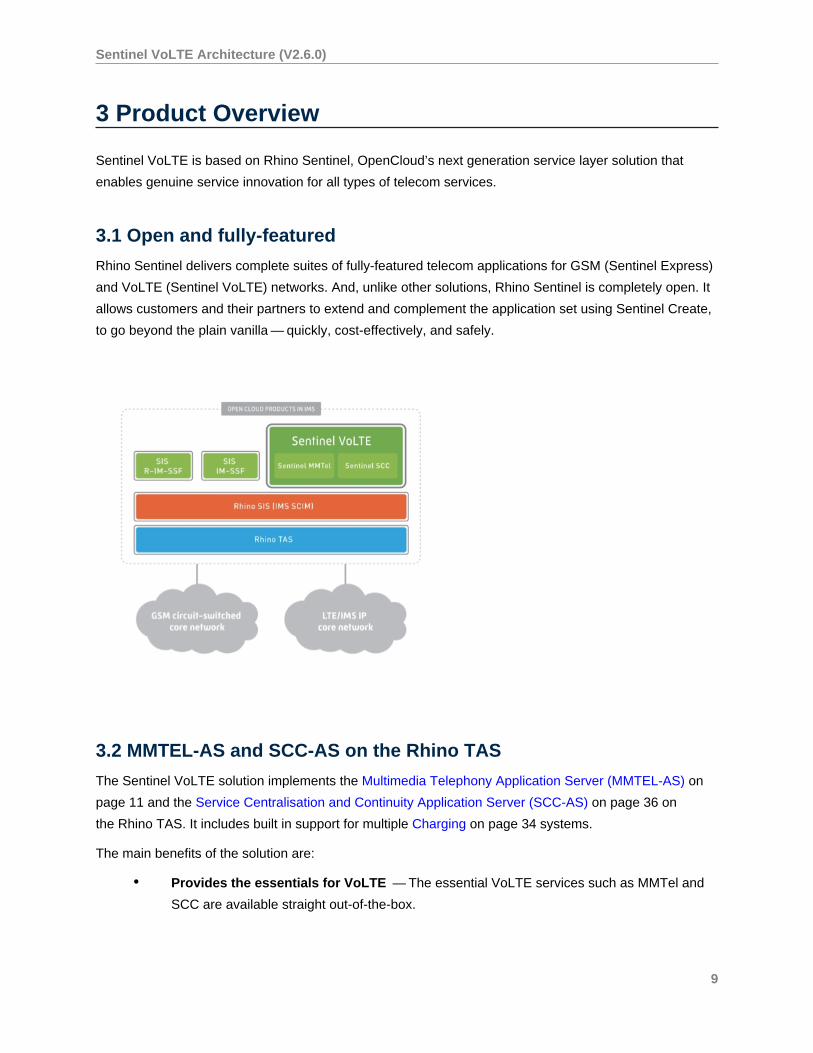
Sentinel VoLTE is based on Rhino Sentinel, OpenCloud’s next generation service layer solution that
enables genuine service innovation for all types of telecom services.
3.1 Open and fully-featured
Rhino Sentinel delivers complete suites of fully-featured telecom applications for GSM (Sentinel Express)
and VoLTE (Sentinel VoLTE) networks. And, unlike other solutions, Rhino Sentinel is completely open. It
allows customers and their partners to extend and complement the application set using Sentinel Create,
to go beyond the plain vanilla — quickly, cost-effectively, and safely.
3.2 MMTEL-AS and SCC-AS on the Rhino TAS
The Sentinel VoLTE solution implements the Multimedia Telephony Application Server (MMTEL-AS) on
page 11 and the Service Centralisation and Continuity Application Server (SCC-AS) on page 36 on
the Rhino TAS. It includes built in support for multiple Charging on page 34 systems.
The main benefits of the solution are:
• Provides the essentials for VoLTE — The essential VoLTE services such as MMTel and
SCC are available straight out-of-the-box.
9
Sentinel VoLTE Architecture (V2.6.0)
• NFV (virtualised model) — Rhino Sentinel can be virtualised and deployed in a private
cloud model, providing more flexible and cost-effective deployment models.
• Open platform and applications — Built on the Sentinel framework, VoLTE services can
be extended and differentiated.
• No vendor lock-in — You can choose to create new services or extend existing services
yourself, with support from the OpenCloud developer ecosystem.
10

Sentinel VoLTE Architecture (V2.6.0)
4 MMTel Services
What does MMTel do?
MMTel (Multi-Media Telephony applications) delivers the core call-control services for voice
and video communications, as well as the supplementary services for VoLTE.
Services General information
GSMA required
Supplementary Services on
page 12
Rhino Sentinel VoLTE delivers these services in an LTE/IMS network,
following the GSMA IR.92 (v9.0) and IR.94 (v10.0) standards.
• With the exception of Message Waiting Indication (MWI),
all IR.92 services are supported within Sentinel VoLTE.
Using Sentinel Create, it is possible to extend the feature
set to very easily include other services.
• Anonymous Call Rejection (ACR) is also supported, even
though it is not an IR.92 service.
Flexible Alerting on page
25
3GPP defines Flexible Alerting in TS 24.239 and the flexible alerting
subscriber data schema is defined in TS 24.239 and TS 29.364 .
The service allows the creation of a group, composed by members,
bounded by a single number, called Pilot Number . When a call to
the Pilot Number is identified VoLTE will alert all the members of the
group and the caller is bounded to the first member of the group that
answers the call.
Explicit Communication
Transfer on page 19
3GPP defines Explicit Communication Transfer in TS 24.629 . The
service allows a member in a communication dialogue called the
transferor to transfer their role in the dialogue to another user called
the transfer-target . The member that remains in the dialogue
during the transfer is called the transfeee .
Session Transfer to Own
Device on page 31
is a service that allows and existing originating or terminating session to
be transfered to another device. The target device is the one that pulls
the session.
11
Sentinel VoLTE Architecture (V2.6.0)
5 GSMA MMTel Supplementary Services
Rhino Sentinel VoLTE delivers these services in an LTE/IMS network, following the GSMA IR.92 (v9.0)
and IR.94 (v10.0) standards.
• With the exception of Message Waiting Indication (MWI), all IR.92 services are supported
within Sentinel VoLTE. Using Sentinel Create, it is possible to extend the feature set to very
easily include other services.
• Anonymous Call Rejection (ACR) is also supported, even though it is not an IR.92 service.
Below are details of GSMA required MMTel supplementary services that Rhino Sentinel VoLTE supports.
5.1 Originating Identification Presentation/Restriction (OIP/OIR) (3GPPTS 24.607)
The OIP service provides the terminating user with the possibility of receiving trusted (network-provided)
identity information in order to identify the originating user.
The OIR service is a service offered to the originating user that restricts presentation of the originating
user’s identity information to the terminating user. Both permanent and temporary modes are supported.
This service is implemented by the features:
• MMTelOIP
• MMTelOIR
5.2 Terminating Identification Presentation/Restriction (TIP/TIR) (3GPPTS 24.608)
The Terminating Identification Presentation (TIP) service provides the originating party with the possibility
of receiving trusted information in order to identify the terminating party.
The Terminating Identification Restriction (TIR) is a service offered to the terminating party which enables
the terminating party to prevent presentation of the terminating identity information to the originating party.
Both permanent and temporary modes are supported.
This service is implemented be the features:
• MMTelTIP
• MMTelTIR
12
Sentinel VoLTE Architecture (V2.6.0)
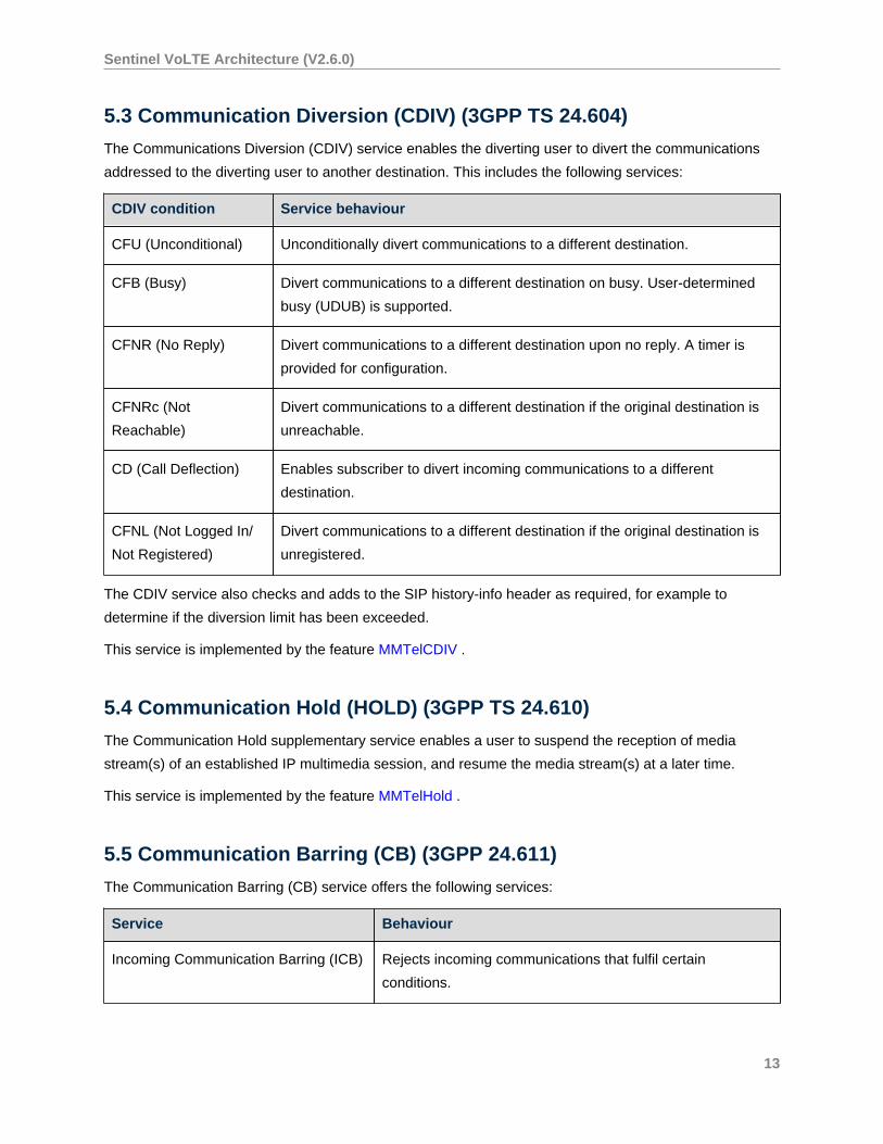
5.3 Communication Diversion (CDIV) (3GPP TS 24.604)
The Communications Diversion (CDIV) service enables the diverting user to divert the communications
addressed to the diverting user to another destination. This includes the following services:
CDIV condition Service behaviour
CFU (Unconditional) Unconditionally divert communications to a different destination.
CFB (Busy) Divert communications to a different destination on busy. User-determined
busy (UDUB) is supported.
CFNR (No Reply) Divert communications to a different destination upon no reply. A timer is
provided for configuration.
CFNRc (Not
Reachable)
Divert communications to a different destination if the original destination is
unreachable.
CD (Call Deflection) Enables subscriber to divert incoming communications to a different
destination.
CFNL (Not Logged In/
Not Registered)
Divert communications to a different destination if the original destination is
unregistered.
The CDIV service also checks and adds to the SIP history-info header as required, for example to
determine if the diversion limit has been exceeded.
This service is implemented by the feature MMTelCDIV .
5.4 Communication Hold (HOLD) (3GPP TS 24.610)
The Communication Hold supplementary service enables a user to suspend the reception of media
stream(s) of an established IP multimedia session, and resume the media stream(s) at a later time.
This service is implemented by the feature MMTelHold .
5.5 Communication Barring (CB) (3GPP 24.611)
The Communication Barring (CB) service offers the following services:
Service Behaviour
Incoming Communication Barring (ICB) Rejects incoming communications that fulfil certain
conditions.
13
Sentinel VoLTE Architecture (V2.6.0)
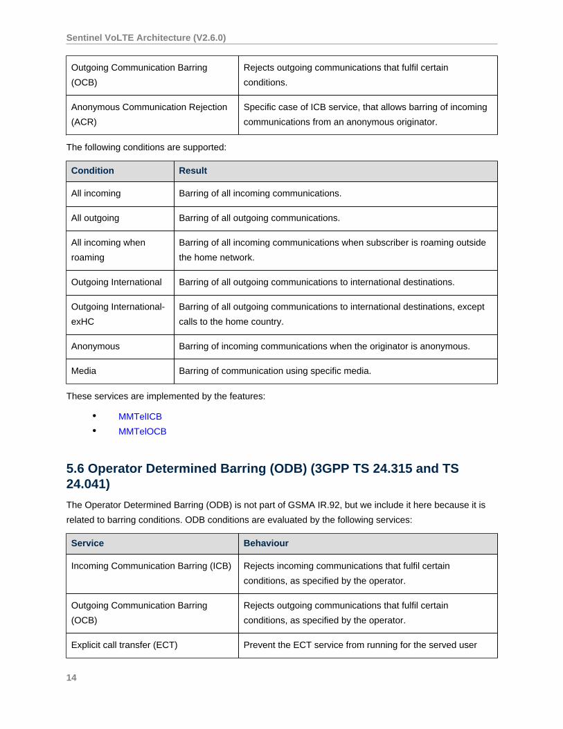
Outgoing Communication Barring
(OCB)
Rejects outgoing communications that fulfil certain
conditions.
Anonymous Communication Rejection
(ACR)
Specific case of ICB service, that allows barring of incoming
communications from an anonymous originator.
The following conditions are supported:
Condition Result
All incoming Barring of all incoming communications.
All outgoing Barring of all outgoing communications.
All incoming when
roaming
Barring of all incoming communications when subscriber is roaming outside
the home network.
Outgoing International Barring of all outgoing communications to international destinations.
Outgoing International-
exHC
Barring of all outgoing communications to international destinations, except
calls to the home country.
Anonymous Barring of incoming communications when the originator is anonymous.
Media Barring of communication using specific media.
These services are implemented by the features:
• MMTelICB
• MMTelOCB
5.6 Operator Determined Barring (ODB) (3GPP TS 24.315 and TS24.041)
The Operator Determined Barring (ODB) is not part of GSMA IR.92, but we include it here because it is
related to barring conditions. ODB conditions are evaluated by the following services:
Service Behaviour
Incoming Communication Barring (ICB) Rejects incoming communications that fulfil certain
conditions, as specified by the operator.
Outgoing Communication Barring
(OCB)
Rejects outgoing communications that fulfil certain
conditions, as specified by the operator.
Explicit call transfer (ECT) Prevent the ECT service from running for the served user
14
Sentinel VoLTE Architecture (V2.6.0)
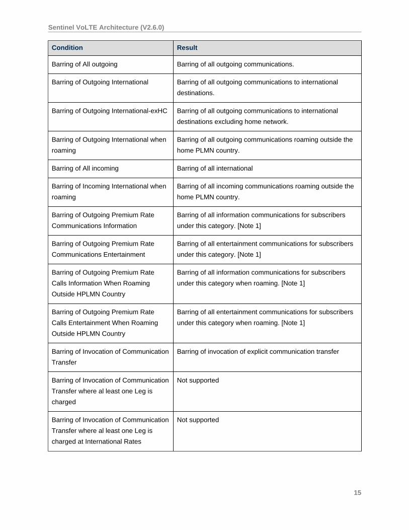
Condition Result
Barring of All outgoing Barring of all outgoing communications.
Barring of Outgoing International Barring of all outgoing communications to international
destinations.
Barring of Outgoing International-exHC Barring of all outgoing communications to international
destinations excluding home network.
Barring of Outgoing International when
roaming
Barring of all outgoing communications roaming outside the
home PLMN country.
Barring of All incoming Barring of all international
Barring of Incoming International when
roaming
Barring of all incoming communications roaming outside the
home PLMN country.
Barring of Outgoing Premium Rate
Communications Information
Barring of all information communications for subscribers
under this category. [Note 1]
Barring of Outgoing Premium Rate
Communications Entertainment
Barring of all entertainment communications for subscribers
under this category. [Note 1]
Barring of Outgoing Premium Rate
Calls Information When Roaming
Outside HPLMN Country
Barring of all information communications for subscribers
under this category when roaming. [Note 1]
Barring of Outgoing Premium Rate
Calls Entertainment When Roaming
Outside HPLMN Country
Barring of all entertainment communications for subscribers
under this category when roaming. [Note 1]
Barring of Invocation of Communication
Transfer
Barring of invocation of explicit communication transfer
Barring of Invocation of Communication
Transfer where al least one Leg is
charged
Not supported
Barring of Invocation of Communication
Transfer where al least one Leg is
charged at International Rates
Not supported
15
Sentinel VoLTE Architecture (V2.6.0)
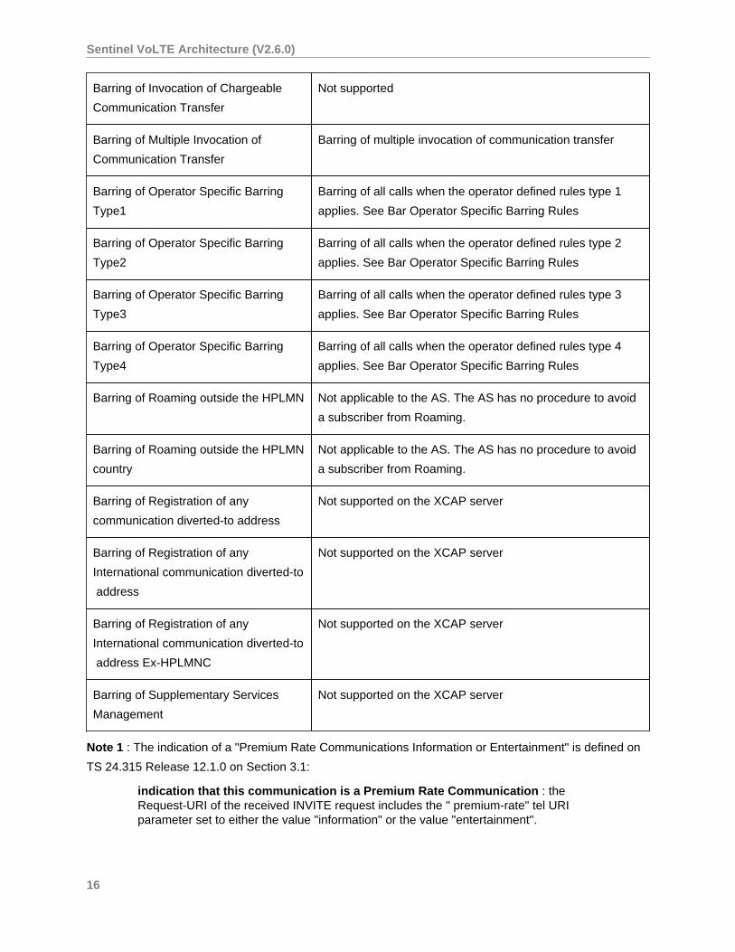
Barring of Invocation of Chargeable
Communication Transfer
Not supported
Barring of Multiple Invocation of
Communication Transfer
Barring of multiple invocation of communication transfer
Barring of Operator Specific Barring
Type1
Barring of all calls when the operator defined rules type 1
applies. See Bar Operator Specific Barring Rules
Barring of Operator Specific Barring
Type2
Barring of all calls when the operator defined rules type 2
applies. See Bar Operator Specific Barring Rules
Barring of Operator Specific Barring
Type3
Barring of all calls when the operator defined rules type 3
applies. See Bar Operator Specific Barring Rules
Barring of Operator Specific Barring
Type4
Barring of all calls when the operator defined rules type 4
applies. See Bar Operator Specific Barring Rules
Barring of Roaming outside the HPLMN Not applicable to the AS. The AS has no procedure to avoid
a subscriber from Roaming.
Barring of Roaming outside the HPLMN
country
Not applicable to the AS. The AS has no procedure to avoid
a subscriber from Roaming.
Barring of Registration of any
communication diverted-to address
Not supported on the XCAP server
Barring of Registration of any
International communication diverted-to
address
Not supported on the XCAP server
Barring of Registration of any
International communication diverted-to
address Ex-HPLMNC
Not supported on the XCAP server
Barring of Supplementary Services
Management
Not supported on the XCAP server
Note 1 : The indication of a "Premium Rate Communications Information or Entertainment" is defined on
TS 24.315 Release 12.1.0 on Section 3.1:
indication that this communication is a Premium Rate Communication : theRequest-URI of the received INVITE request includes the " premium-rate" tel URIparameter set to either the value "information" or the value "entertainment".
16
Sentinel VoLTE Architecture (V2.6.0)
For more information see Operator Determined Barring .
5.7 Explicit Call Transfer (ECT) (3GPP TS24.629)
The Explicit Call Transfer (ECT) service enables a transferor to transfer the call to a transfer target.
The transfer can be a blind transfer or a consultative transfer. In a blind transfer the transferor does not
consult the transfer target before the transfer, In a consultative transfer the transferor does consult the
transfer target.
The Explicit Call Transfer service uses 3PCC Call Transfer Procedures in case the transferee can not
handle the transfer request.
This service is implemented by the feature MMTelECT .
5.8 Communication Waiting (CW) (3GPP TS24.615)
The Communication Waiting (CW) service enables a terminating party to be informed at the time that a
new communication is requested. The user then has the choice of accepting, rejecting, or ignoring the
incoming communication.
This feature is implemented by the feature MMTelCW .
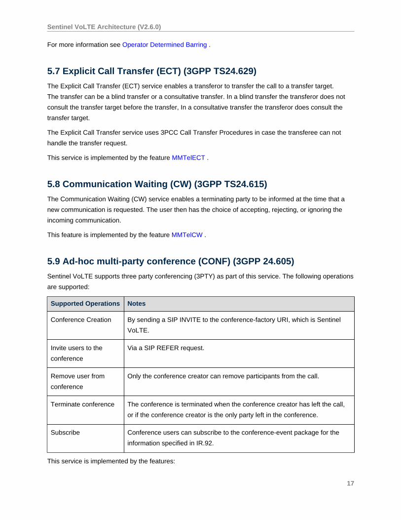
5.9 Ad-hoc multi-party conference (CONF) (3GPP 24.605)
Sentinel VoLTE supports three party conferencing (3PTY) as part of this service. The following operations
are supported:
Supported Operations Notes
Conference Creation By sending a SIP INVITE to the conference-factory URI, which is Sentinel
VoLTE.
Invite users to the
conference
Via a SIP REFER request.
Remove user from
conference
Only the conference creator can remove participants from the call.
Terminate conference The conference is terminated when the conference creator has left the call,
or if the conference creator is the only party left in the conference.
Subscribe Conference users can subscribe to the conference-event package for the
information specified in IR.92.
This service is implemented by the features:
17
Sentinel VoLTE Architecture (V2.6.0)
• MMTel Conference
• MMTel Conference Subscription
5.10 Anonymous Call Rejection (ACR) (3GPP TS24.611)
See Communication Barring on page 13 .
5.10.1 XCAP interface (Ut)
Sentinel VoLTE supports the XCAP interface over the Ut reference point between the UE and MMTEL-
AS, as per 3GPP TS24.623.
For more information please refer to the XCAP Support on page 48 section. For information on the
Authorization Proxy please refer to Sentinel Authentication Gateway .
18
Sentinel VoLTE Architecture (V2.6.0)
6 Explicit Communication Transfer
3GPP defines Explicit Communication Transfer in TS 24.629 . The service allows a member in a
communication dialogue called the transferor to transfer their role in the dialogue to another user
called the transfer-target . The member that remains in the dialogue during the transfer is called the
transfeee .
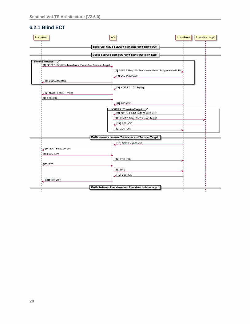
6.1 Communication Transfer Modes
There are two scenarios in which a transfer can be initiated:
• Consultive Transfer: The transferor has a consultation communication with the transfer
target. This allows:
• Classical charging models
• Anonymization of the transfer target
• Blind Transfer: The transferee has no consultative communication with the transfer target
Consultative ECT using the 3pcc procedure does not support reusing the existing leg between the AS
and the transfer-target, instead a new leg is created to link to the transferee.
Under certain circumstances the standard signalling flows may be interrupted and the feature will set up
the new dialogue using Third Party Call Control (3pcc) procedures.
For feature details see MMTelECT .
6.2 Example Explicit Communication Transfer Call Flows
Various IMS core elements and some SIP messages are omitted from the call flow diagramsfor the sake of clarity.
19
Sentinel VoLTE Architecture (V2.6.0)
6.2.1 Blind ECT
20
Sentinel VoLTE Architecture (V2.6.0)
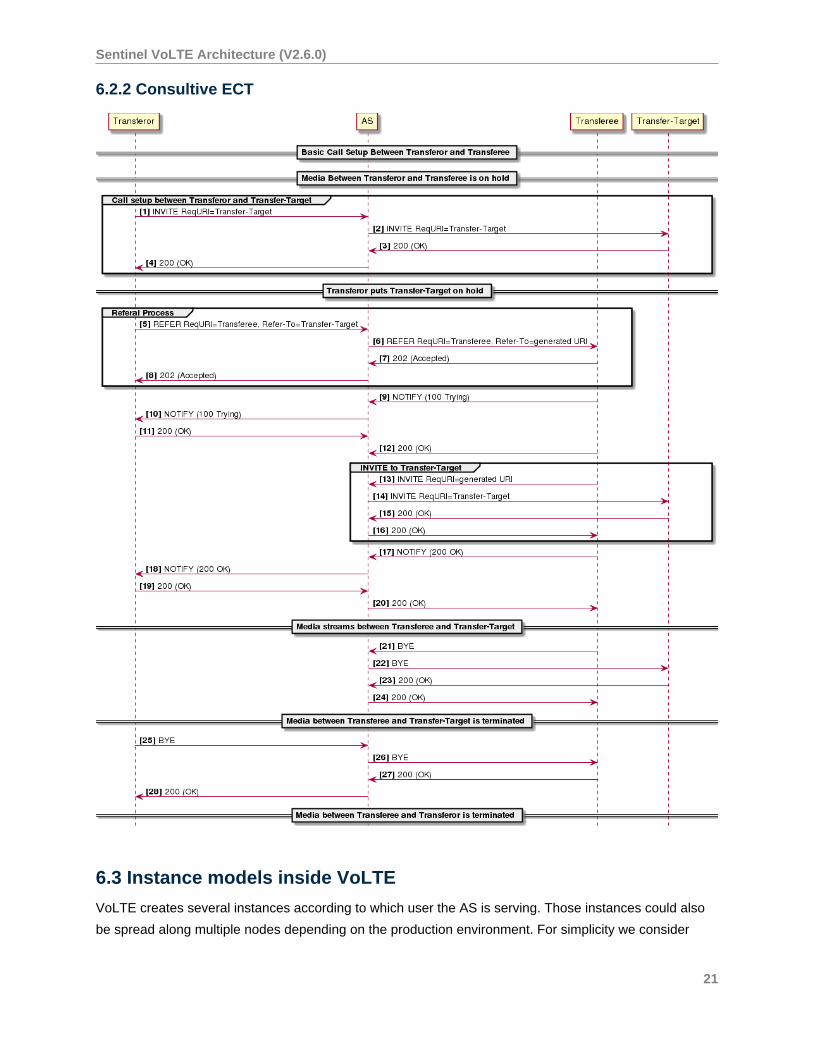
6.2.2 Consultive ECT
6.3 Instance models inside VoLTE
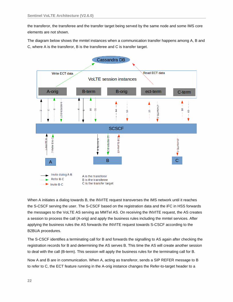
VoLTE creates several instances according to which user the AS is serving. Those instances could also
be spread along multiple nodes depending on the production environment. For simplicity we consider
21
Sentinel VoLTE Architecture (V2.6.0)
the transferor, the transferee and the transfer target being served by the same node and some IMS core
elements are not shown.
The diagram below shows the mmtel instances when a communication transfer happens among A, B and
C, where A is the transferor, B is the transferee and C is transfer target.
When A initiates a dialog towards B, the INVITE request transverses the IMS network until it reaches
the S-CSCF serving the user. The S-CSCF based on the registration data and the iFC in HSS forwards
the messages to the VoLTE AS serving as MMTel AS. On receiving the INVITE request, the AS creates
a session to process the call (A-orig) and apply the business rules including the mmtel services. After
applying the business rules the AS forwards the INVITE request towards S-CSCF according to the
B2BUA procedures.
The S-CSCF identifies a terminating call for B and forwards the signalling to AS again after checking the
registration records for B and determining the AS serves B. This time the AS will create another session
to deal with the call (B-term). This session will apply the business rules for the terminating call for B.
Now A and B are in communication. When A, acting as transferor, sends a SIP REFER message to B
to refer to C, the ECT feature running in the A-orig instance changes the Refer-to-target header to a
22
Sentinel VoLTE Architecture (V2.6.0)
generated URI (ECT URI) and stores the information in the database. This change has the objective
to maintain the AS in the signaling. The REFER message transverses all the existing instances until
it reaches the B party. When B receives the REFER message, it initiates a new dialog towards the
generated ECT URI.
The INVITE request sent by B creates a new mmtel instance for B originating (B-orig), that will apply the
proper business rules for this session. When the INVITE request reaches the AS again, a terminating
instance is created (ect-term in the picture). This instance will change the ECT URI to the proper target
destination stored in the database and send the INVITE request towards C. On receiving the INVITE
request for C,the S-CSCF identifies the C is served by the same AS and forward the INVITE request to
the AS. When the AS receives the INVITE request to C, it creates a terminating instance for C (C-term).
This instance will apply the business rules for this terminating call and forwards the INVITE request to C.
C accepts the call and eventually the call session between A and B will finish.
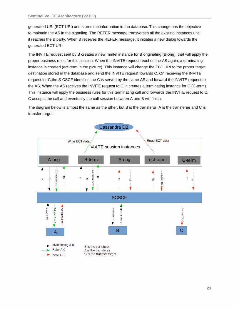
The diagram below is almost the same as the other, but B is the transferor, A is the transferee and C is
transfer target.
23
Sentinel VoLTE Architecture (V2.6.0)
For this scenario, when B sends a REFER to A to refer to C, the new ECT URI is generated on the B-term
instance. When A sends the INVITE to the ECT URI, a new instance is created for A (A-orig'). The flow
happens the same as the other.
6.4 Charging
The indication that the Explicit Communication Transfer service happened is present on the charging
procedures (Online charging and CDR generation). The Service-Type AVP set to 20 indicates the
ECT service was used. These information is set on the instances where it is possible to identify the ECT
service: A-orig , ect-term and B-term when acting as transferor.
The Service-Type AVP is present in MMTel-Information AVP . For more information see
Populated AVPs in the MMTel-Information AVP .
6.4.1 Out of Scope
Consultative ECT and REFER out of dialog are not supported. To implement such support it is necessary
to track all MMTel call sessions in progress along multiple nodes.
24
Sentinel VoLTE Architecture (V2.6.0)
7 Flexible Alerting
7.1 What is Flexible Alerting
3GPP defines Flexible Alerting in TS 24.239 and the flexible alerting subscriber data schema is defined in
TS 24.239 and TS 29.364 . The service allows the creation of a group, composed by members, bounded
by a single number, called Pilot Number . When a call to the Pilot Number is identified VoLTE will
alert all the members of the group and the caller is bounded to the first member of the group that answers
the call.
7.2 Group Members
The group of identities that may be contacted by the Flexible Alerting feature is called the FA Group .
The FA Group can be of two types:
• multiple-users or
• single-user
The difference between then consists on how to deal with the SIP Responses from the FA Group
members.
For single-user
• The Pilot Number is considered Busy when the any of the members are busy and no 200
(OK) was received before.
• The Pilot Number is considered in a state of Not Reachable when all group members are
in a state of not reachable.
• The Pilot Number is considered in a state of No Reply when all group members are in a
state of no reply.
For multiple-users
• The Pilot Number is considered Busy when all group members are busy.
• The Pilot Number is considered Not Reachable when all group members are not
reachable.
• The Pilot Number is considered No Reply when all group members are in a state of no
reply.
7.3 Alerting type
There are two ways of alerting the group members:
25
Sentinel VoLTE Architecture (V2.6.0)
• in sequential or
• in parallel
In sequential way the service alerts the FA Group members one after the other, while in parallel
way the service alerts FA Group members all at once.
Flexible Alerting allows the call to continue after final responses on one or more group members.
7.4 Flexible Alerting Features
OpenCloud’s Flexible Alerting supports both Parallel or Sequential alerting mode by a configuration under
MMTelDetermineFAConfigProfileTable . The configuration table can be accessed through REM
and is specified using the MMTelDetermineFAConfigProfileTable profile table name. The feature
profile is scoped by the sentinel key and the pilot number, meaning that each Pilot Number requires a
profile, otherwise VoLTE will fallback to a default profile not scoped by the Pilot Number .
7.5 Flexible Alerting Mode Examples Call Flow
Various IMS core elements and some SIP messages are omitted from the call flow diagramsfor the sake of clarity.
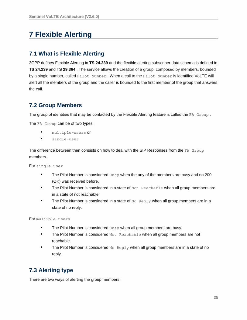
7.5.1 Parallel Alerting for group type of multiple-users
In the following Flexible Alerting call example there are two members in the FA group configured to
receive the call in the HSS Service Data. The alerting mode is set to Parallel, so all members will be
alerted at the same time. The Member B answers the call.
26
Sentinel VoLTE Architecture (V2.6.0)
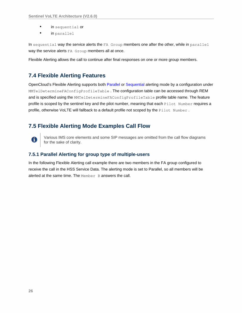
7.5.2 Parallel Alerting for group type of single-user
In the following Flexible Alerting call example there are two members in the FA group configured to
receive the call in the HSS Service Data. The alerting mode is set to Parallel, so all members will be
alerted at the same time. The Member B responds with 486 (Busy here) and the service cancel the
ongoing alerting and finish the session.
27
Sentinel VoLTE Architecture (V2.6.0)
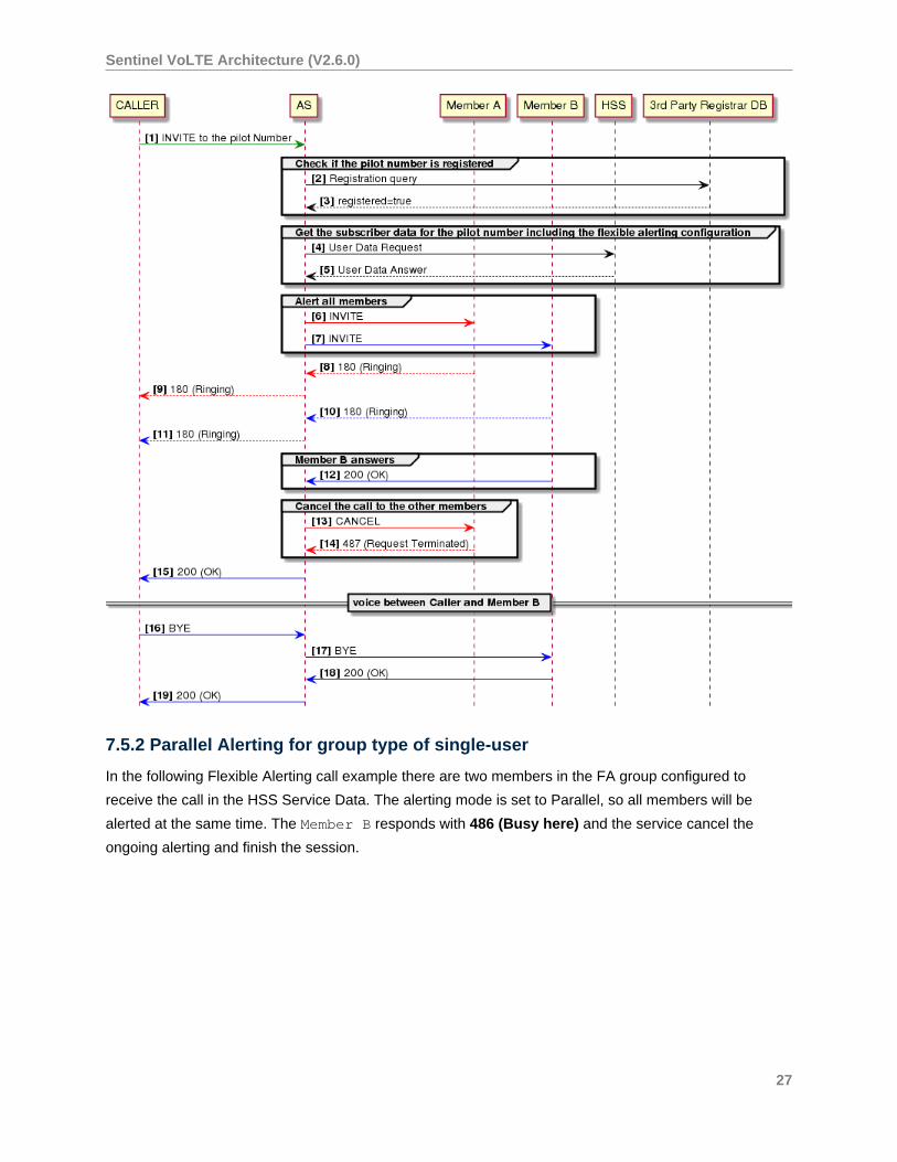
7.5.3 Sequential Alerting for group of type multiple-users
In the following Flexible Alerting call example there are two members in the FA group configured to
receive the call in the HSS Service Data. The alerting mode is set to Sequential, so all members will be
alerted one after the other. The Member B answers the call.
28
Sentinel VoLTE Architecture (V2.6.0)
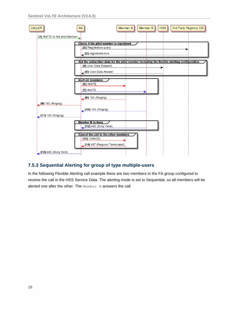
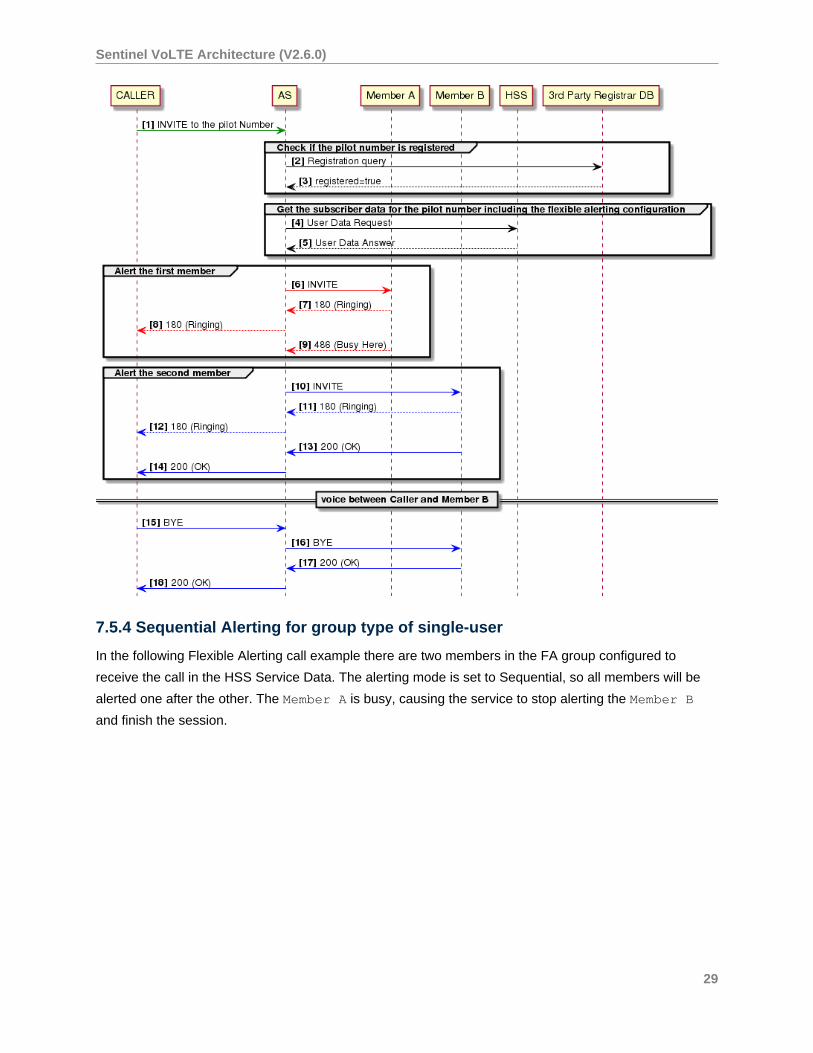
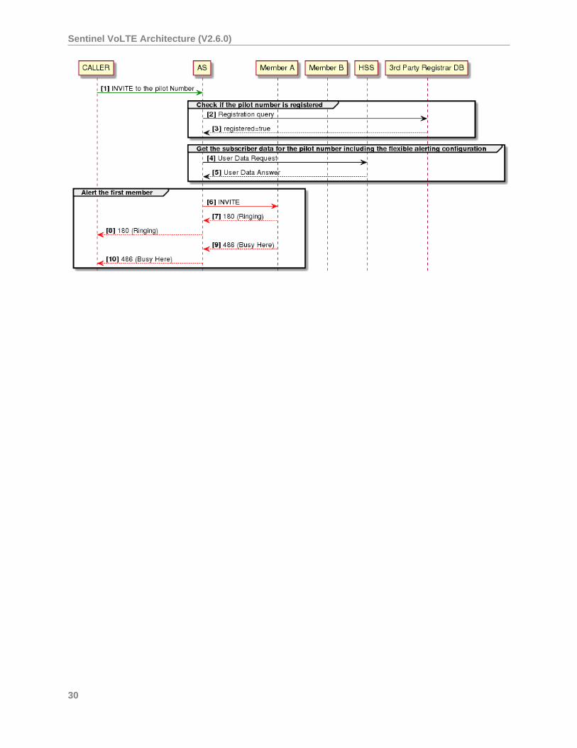
7.5.4 Sequential Alerting for group type of single-user
In the following Flexible Alerting call example there are two members in the FA group configured to
receive the call in the HSS Service Data. The alerting mode is set to Sequential, so all members will be
alerted one after the other. The Member A is busy, causing the service to stop alerting the Member B
and finish the session.
29
Sentinel VoLTE Architecture (V2.6.0)
30
Sentinel VoLTE Architecture (V2.6.0)
8 Session Transfer to Own Device
is a service that allows and existing originating or terminating session to be transfered to another device.
The target device is the one that pulls the session. The service is experimental and has some constraints
(see Pre requisites on page 31 ).
8.1 Service description
A subscriber with 2 registered devices (UE1 and UE2) under the same IMPU makes a call to another
device B from UE1. Once the call between UE1 and B is established, the subscriber can use the
registered UE2 to pull the call to that device. The user calls a special URI previously configured in the AS
(see DetermineVoltePlanId ). The AS will verify the called URI is a Session Transfer to Own Device URI
service and pull the call to the UE2. The UE1 will be disconnected as soon as the session between UE2
and B is established.
The service also works for the terminating case, which means that the subscriber B receiving a call can
also use another registered device (B') under the same IMPU to pull the call.
8.2 Pre requisites• the subscriber has to have the STOD service enabled (see MMTelStodEnabled )
• the special number has to be configured in the AS (see DetermineVoltePlanId )
• the service supports just one active session to be transfered
• both sessions have to be in the same VoLTE node
• the provisioning is done by feature profile
• see the DetermineVoltePlanId for the MmtelTransferNumber configuration
• see the MMTelStodEnabled for the subscriber provisioning
8.3 Basic flow
The flow below shows a basic call flow with a simple transfer.
31

Sentinel VoLTE Architecture (V2.6.0)
8.4 Features
The service is composed of several features:
32

Sentinel VoLTE Architecture (V2.6.0)
• DetermineVoltePlanId
• MMTelStodEnabled
• MMTelStodBind
• MMTelStodTriggerAnchor
• MMTelStodProcessHandover
The interactions among the features are show below:
The DetermineVoltePlanId sets the session to mmtel and also checks if the request URI is for the STOD
service.
The MMTelStodEnabled checks its profile to assert that the user is allowed to trigger the service and
if allowed the MMTelStodBind feature will bind the session to an ACI name. This ACI name will be
reconstructed by the MMTelStodTriggerAnchor feature on receiving a transfer INVITE and will route the
transfer INVITE to the existing session.
The MMTelStodProcessHandover intercepts the transfer INVITE and do the procedures to connect the
existing called party to the new calling party.
33
Sentinel VoLTE Architecture (V2.6.0)
9 Charging
The Sentinel framework, which Sentinel VoLTE is based on, uses the Diameter Ro interface to the OCS
to enable online charging.
For more details on this please see the Sentinel product documentation.
Highlighted below are the key pieces of charging functionality:
• Multiple OCS support on page 34
• Re-authorization on page 35
• CDR generation on page 35
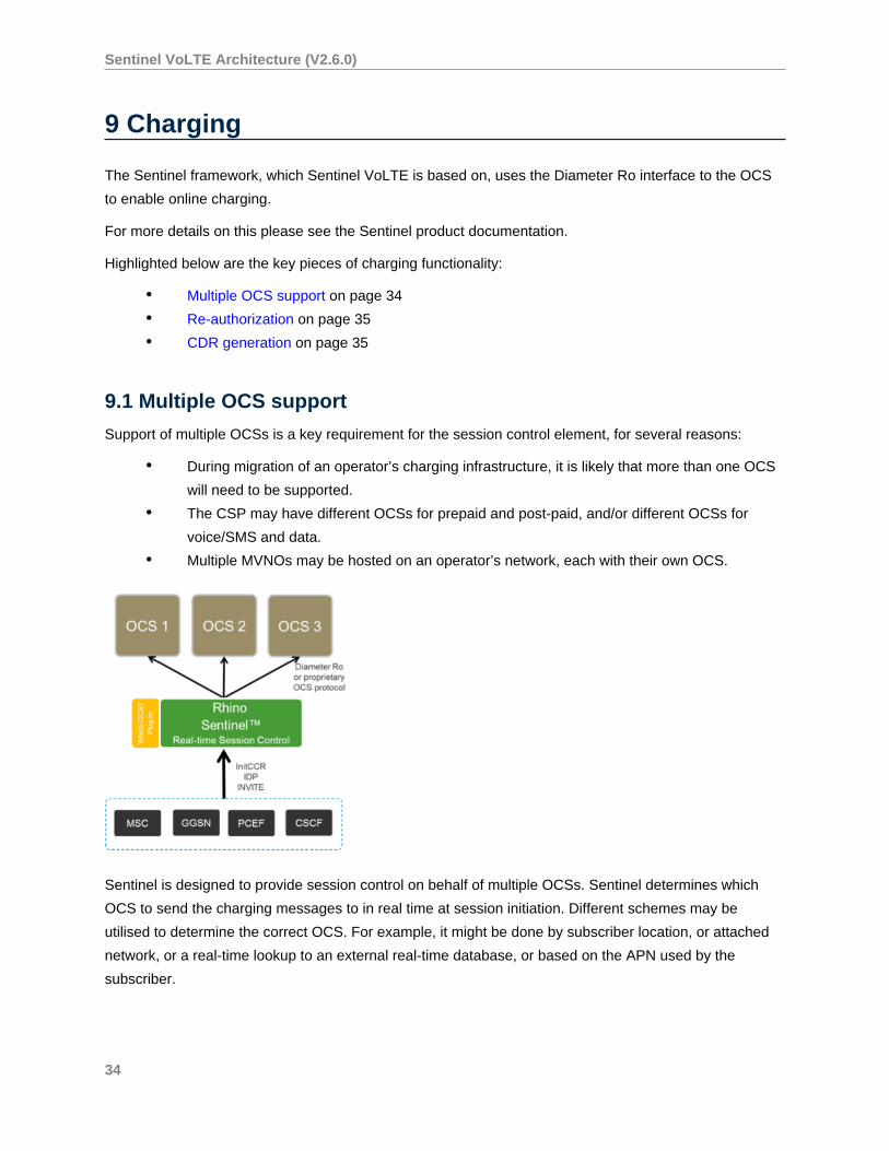
9.1 Multiple OCS support
Support of multiple OCSs is a key requirement for the session control element, for several reasons:
• During migration of an operator’s charging infrastructure, it is likely that more than one OCS
will need to be supported.
• The CSP may have different OCSs for prepaid and post-paid, and/or different OCSs for
voice/SMS and data.
• Multiple MVNOs may be hosted on an operator’s network, each with their own OCS.
Sentinel is designed to provide session control on behalf of multiple OCSs. Sentinel determines which
OCS to send the charging messages to in real time at session initiation. Different schemes may be
utilised to determine the correct OCS. For example, it might be done by subscriber location, or attached
network, or a real-time lookup to an external real-time database, or based on the APN used by the
subscriber.
34
Sentinel VoLTE Architecture (V2.6.0)
9.2 Re-authorization
In the middle of a SIP session, media streams may be added and removed, as well as having their
codecs changed. When codecs change, Sentinel VoLTE consults its SDP codec configuration to
determine if the change was a “meaningful” change from a charging perspective (for example, if an audio
call was changed to an audio and video call).
If a change is deemed meaningful, Sentinel performs client-initiated re-authorization towards the Online
Charging System. If a change is not meaningful, the current credit reservation remains valid. This is
explained in more detail in the Online Charging on page 60 section.
9.3 CDR generation
Rhino Sentinel writes a CDR for all charging session attempts, whether the session was successfully
completed or could not be completed due to some error.
CDRs generated by Sentinel may also be used for offline charging situations.
The CDRs are written to a file in a configurable location and contain all the parameters that are available
to the Rhino Sentinel. More detail on Sentinel VoLTE CDRs can be found in the Charging Information
section of the Sentinel VoLTE Administration Guide .
9.4 Use of a Prepaid SCP via CAP
Sentinel VoLTE can be installed to use a Prepaid Service Control Point as the OCS, rather than
communicating via Diameter Ro to the OCS. The use of Ro, CAP or neither for online charging is enabled
through the Selection of charging mode . In all cases, Sentinel VoLTE will write a CDR for the session.
35
Sentinel VoLTE Architecture (V2.6.0)
10 SCC-AS Services
What are SCC-AS services?
The SCC-AS is a home network element that enables three main functions:
• IMS centralised services (ICS) on page 36• Terminating Access Domain Selection (T-ADS) on page 37• Service Continuity on page 39
Sentinel SCC is compliant with GSMA IR.64 (v12.0) IMS Service Centralization and Continuity
Guidelines.
10.1 IMS Centralised Services (ICS) support
True ICS rely on either enhanced handsets (ICS UEs) or enhanced MSC Servers (e-MSS).
The ICS approach stated in GSMA IR.64 is based on the e-MSS, and therefore ICS UEs are not currently
considered in Sentinel VoLTE. However this support can easily be added to the solution.
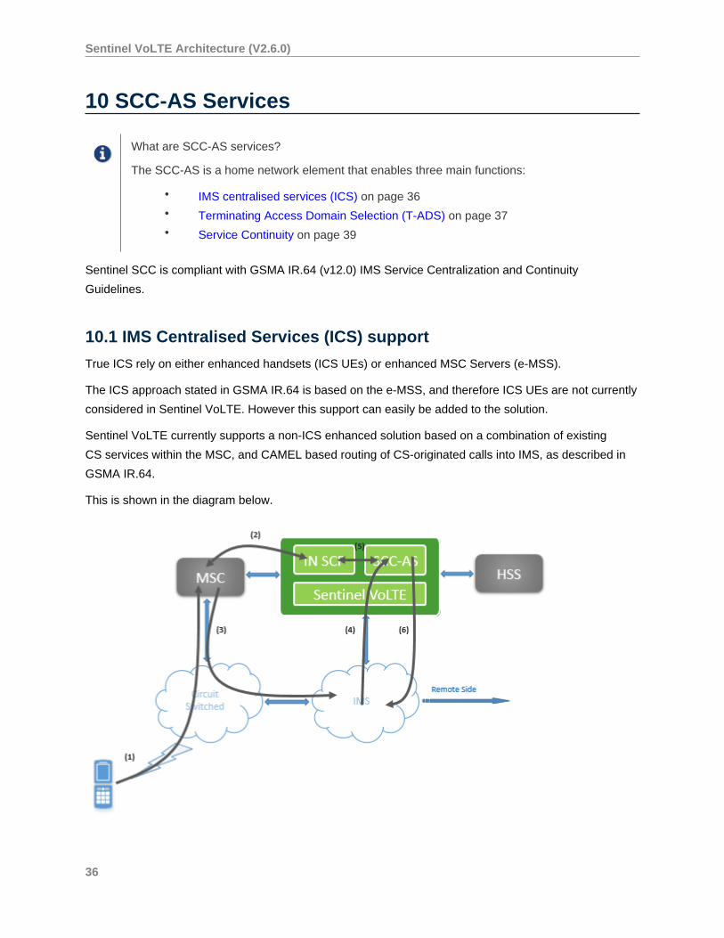
Sentinel VoLTE currently supports a non-ICS enhanced solution based on a combination of existing
CS services within the MSC, and CAMEL based routing of CS-originated calls into IMS, as described in
GSMA IR.64.
This is shown in the diagram below.
36
Sentinel VoLTE Architecture (V2.6.0)
In this diagram:
1. The UE attempts a CS originated call.
2. The MSC VLR sends an InitialDP to the IN SCP function in Sentinel VOLTE, which then
returns an IMS Routing Number (IMRN).
3. The CS network uses the IMRN to route toward the IMS.
4. The IMS network then routes the call based on the IMRN contained within the Request-URI
of the SIP INVITE.
5. The SCC-AS correlates the SIP INVITE with the received InitialDP.
6. The SCC-AS generates an IMS session on behalf of the CS user.
This mechanism can be considered as “network-facilitated” ICS.
10.2 Terminating Access Domain Selection (T-ADS)
For sessions that terminate in the IMS domain, the SCC-AS is responsible for deciding whether to route
the session to the CS network or the PS network — depending on registration, network characteristics,
and subscriber preferences. This is called T-ADS.
Out of the box, Sentinel VoLTE supports a standard algorithm for T-ADS, which is fully extensible and
customisable by a third party:
• Sentinel VoLTE optionally performs a Diameter Sh lookup on the HSS to determine “IMS
voice over PS Session Supported Indication”
• The Circuit Switch Routing number is formed through either querying the HSS for the
Correlation MSISDN (C-MSISDN), or the HLR for the Mobile Station Roaming Number
(MSRN)
• The third-party registration state is also examined, in order to determine subscriber state.
In addition to the standard T-ADS algorithm, Sentinel VoLTE support different strategies for routing
signaling towards PS or CS domains. These include:
• Support for flexible sequential routing. Sentinel VoLTE can send sends INVITEs towards the
PS or CS domains either order (PS first, or CS first).
• Support for routing towards a single domain only (either PS only, or CS only)
• Support for parallel routing. Sentinel VoLTE initiates a Parallel Fork, sending INVITE
messages towards the PS and CS domains simultaneously. The selected access network
depends on received responses.
For further details refer to the Terminating Access Domain Selection Features section of the
Administration Guide.
37
Sentinel VoLTE Architecture (V2.6.0)
10.2.1 Computing the Circuit Switched Routing Number
The Circuit Switched Routing Number (CSRN) is generated by retrieving either the C-MSISDN from
the HSS, or the MSRN from the HLR, and adding a routing prefix to it. When fetching the C-MSISDN
from the HSS an “Sh-Pull” is used. Alternatively if requesting the MSRN from the HLR a “Send Routing
Information” operation is used.
1. The SCC-AS optionally uses an “Sh-Pull” operation toward the HSS requesting the “IMS
voice over PS Session Supported Indication”
2. The SCC-AS uses the retrieved information to determine where to route the call, depending
on the algorithm described above. In case the session needs to be routed to CS, the SCC-
AS re-targets the session to the CSRN — in other words, the Request-URI of the INVITE is
now the CSRN.
The Circuit Switched Routing Number (CSRN) is used to force the S-CSCF to invoke the BGCF, which
in turn directs the session toward an appropriate MSC-S/MGCF entry point to the CS network. When the
SCC-AS changes the Request-URI to the CSRN, the S-CSCF will halt iFC processing and attempt to
locate the new Request-URI target. Since the CSRN is not an IMS identity, the BGCF is used to route
toward the CS domain.
Sentinel VoLTE contains configuration such that the MSRN and/or CMSISDN for a subscriber is able to
be fetched upon initial registration. It is then stored into Sentinel Registrar data storage.
During INVITE processing, Sentinel Registrar data storage is consulted. If it contains an MSRN, or
CMSISDN, the Registration time value is used. If there is no MSRN or CMSISDN available in the
Registration Data store, the HLR or HSS are consulted during INVITE processing prior to computation of
the CSRN.
10.2.2 The OC-Terminating-Domain Header
Sentinel VoLTE T-ADS implementation inserts a header in all provisional and success responses to an
initial INVITE. This header provides information about the terminating access domain for the response.
This allows systems "upstream" of the SCC-AS to alter their charging, if required.
OpenCloud’s MMTel-AS and IM-SSF include behaviour to alter charging if the terminating domain is
PS=WLAN (WiFi access).
For further details of this header refer to the T-ADS section of the Sentinel VoLTE Administration Guide .
10.2.3 Extensibility
The Sentinel implementation of T-ADS is split into three features — a centralized decision, and two
routing features. This approach coupled with the Sentinel feature-based implementation model allows
operators to replace or augment default processing. In addition, the CSRN is calculated in a flexible way
meaning that different "sources" for the CSRN can be used to compute the CSRN.
For example,
38
Sentinel VoLTE Architecture (V2.6.0)
• Route a terminating call to CS based on the decision taken for a previous call, in order to
reduce HSS traffic.
• Route a terminating call to CS if the subscriber is on PS but PS coverage in that location is
deemed inadequate.
• Route a terminating call to PS and CS simultaneously and select the network with best
media offer.
Sentinel provides access to T-ADS context and TAS capabilities such as database queries, signalling
queries, and cache access, enabling custom algorithms to be built easily.
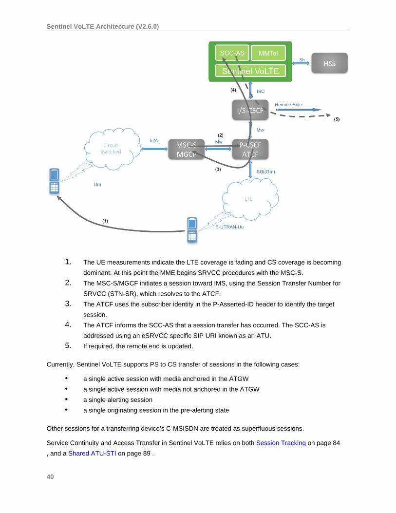
10.3 Service Continuity and Access Transfer
Sentinel VoLTE supports enhanced Single Radio Voice Call Continuity (eSRVCC — from 3GPP Rel 10);
providing bi-directional transfer of sessions between the IMS packet-switched and GSM circuit-switched
networks. This mechanism relies on the presence of an ATCF (Access Transfer Control Function) in the
operator’s network.
ATCF and ATGW were introduced as an enhancement to the base SRVCC specification as a means
to localise media transfer. Previously, the new SDP offer from the MSC-S/MGCF had to be negotiated
hop-by-hop to the remote UE, which incurred a delay. Using the ATCF, which architecturally sits in the
Serving/Visited network — alongside the MSC-S/MGCF — normally entails a single hop of SDP Offer/
Answer, which represents a significant optimisation of the session transfer.
39
Sentinel VoLTE Architecture (V2.6.0)
1. The UE measurements indicate the LTE coverage is fading and CS coverage is becoming
dominant. At this point the MME begins SRVCC procedures with the MSC-S.
2. The MSC-S/MGCF initiates a session toward IMS, using the Session Transfer Number for
SRVCC (STN-SR), which resolves to the ATCF.
3. The ATCF uses the subscriber identity in the P-Asserted-ID header to identify the target
session.
4. The ATCF informs the SCC-AS that a session transfer has occurred. The SCC-AS is
addressed using an eSRVCC specific SIP URI known as an ATU.
5. If required, the remote end is updated.
Currently, Sentinel VoLTE supports PS to CS transfer of sessions in the following cases:
• a single active session with media anchored in the ATGW
• a single active session with media not anchored in the ATGW
• a single alerting session
• a single originating session in the pre-alerting state
Other sessions for a transferring device’s C-MSISDN are treated as superfluous sessions.
Service Continuity and Access Transfer in Sentinel VoLTE relies on both Session Tracking on page 84
, and a Shared ATU-STI on page 89 .
40

Sentinel VoLTE Architecture (V2.6.0)
Features that implement Access Transfer are documented in the Packet Switched to Circuit Switched
Access Transfer Features section of the administration guide.
41
Sentinel VoLTE Architecture (V2.6.0)
11 Architecture Overview
OpenCloud’s Rhino Sentinel VoLTE product implements the Service Centralisation and Continuity
Application Server (SCC-AS) on page 36 and Multimedia Telephony Application Server (MMTel-AS) on
page 11 .
Sentinel VoLTE is based on OpenCloud’s Sentinel architecture and frameworks, and
automatically gains from all benefits of Sentinel, including:
• flexible online/offline/hybrid charging through configuration• remaining an open system… after it is deployed• feature-based extensibility.
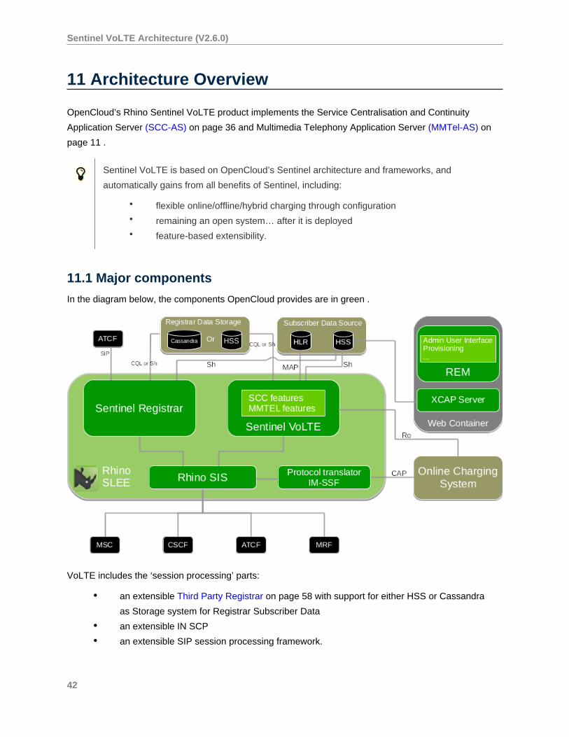
11.1 Major components
In the diagram below, the components OpenCloud provides are in green .
VoLTE includes the ‘session processing’ parts:
• an extensible Third Party Registrar on page 58 with support for either HSS or Cassandra
as Storage system for Registrar Subscriber Data
• an extensible IN SCP
• an extensible SIP session processing framework.
42
Sentinel VoLTE Architecture (V2.6.0)
It provides web-server based infrastructure for:
• the administration web user interface (Rhino Element Manager)
• RESTful Provisioning Services
• an XCAP Server for UE self-provisioning
• JSLEE services.
It also provides Online Charging Support on page 60 by either using the Ro interface or CAP interface
with IM-SSF Protocol Translator.
11.1.1 JSLEE services
Sentinel VoLTE’s JSLEE services are based on OpenCloud’s Sentinel architecture and frameworks.
It includes four JSLEE services:
• Sentinel-based SIP Third Party Registrar (for SCC and MMTEL)
• Sentinel-based SIP based Service — hosting the ‘main session processing logic’ (for SCC
and MMTEL)
• Sentinel-based IN SCP Service (for SCC)
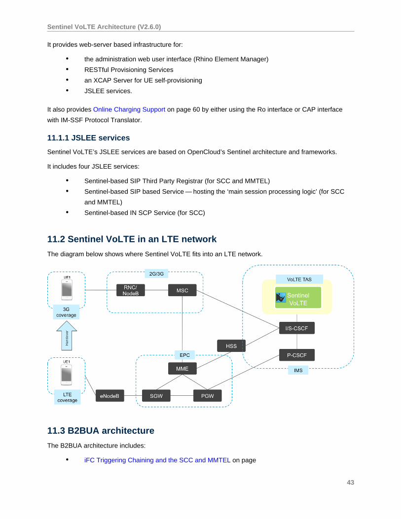
11.2 Sentinel VoLTE in an LTE network
The diagram below shows where Sentinel VoLTE fits into an LTE network.
11.3 B2BUA architecture
The B2BUA architecture includes:
• iFC Triggering Chaining and the SCC and MMTEL on page
43
Sentinel VoLTE Architecture (V2.6.0)
• Co-location using the Rhino SIS on page 44
• Optimised performance using Sentinel on page
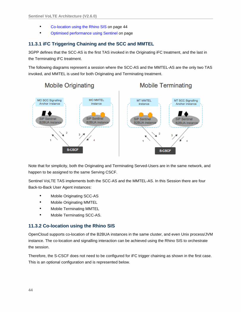
11.3.1 iFC Triggering Chaining and the SCC and MMTEL
3GPP defines that the SCC-AS is the first TAS invoked in the Originating iFC treatment, and the last in
the Terminating iFC treatment.
The following diagrams represent a session where the SCC-AS and the MMTEL-AS are the only two TAS
invoked, and MMTEL is used for both Originating and Terminating treatment.
Note that for simplicity, both the Originating and Terminating Served-Users are in the same network, and
happen to be assigned to the same Serving CSCF.
Sentinel VoLTE TAS implements both the SCC-AS and the MMTEL-AS. In this Session there are four
Back-to-Back User Agent instances:
• Mobile Originating SCC-AS
• Mobile Originating MMTEL
• Mobile Terminating MMTEL
• Mobile Terminating SCC-AS.
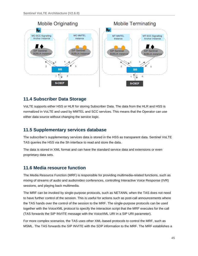
11.3.2 Co-location using the Rhino SIS
OpenCloud supports co-location of the B2BUA instances in the same cluster, and even Unix process/JVM
instance. The co-location and signalling interaction can be achieved using the Rhino SIS to orchestrate
the session.
Therefore, the S-CSCF does not need to be configured for iFC trigger chaining as shown in the first case.
This is an optional configuration and is represented below.
44
Sentinel VoLTE Architecture (V2.6.0)
11.4 Subscriber Data Storage
VoLTE supports either HSS or HLR for storing Subscriber Data. The data from the HLR and HSS is
normalized in VoLTE and used by MMTEL and SCC services. This means that the Operator can use
either data source without changing the service logic.
11.5 Supplementary services database
The subscriber’s supplementary services data is stored in the HSS as transparent data. Sentinel VoLTE
TAS queries the HSS via the Sh interface to read and store the data.
The data is stored in XML format and can have the standard service data and extensions or even
proprietary data sets.
11.6 Media resource function
The Media Resource Function (MRF) is responsible for providing multimedia-related functions, such as
mixing of streams of audio and audio/video conferences, controlling Interactive Voice Response (IVR)
sessions, and playing back multimedia.
The MRF can be invoked by single-purpose protocols, such as NETANN, when the TAS does not need
to have further control of the session. This is useful for actions such as post-call announcements where
the TAS hands over the control of the session to the MRF. The single-purpose protocols can be used
together with the VoiceXML protocol to specify the interaction script that the MRF executes for the call
(TAS forwards the SIP INVITE message with the VoiceXML URI in a SIP URI parameter).
For more complex scenarios, the TAS uses other XML-based protocols to control the MRF, such as
MSML. The TAS forwards the SIP INVITE with the SDP information to the MRF. The MRF establishes a
45
Sentinel VoLTE Architecture (V2.6.0)
RTP stream with the UE. After that, the TAS sends MSML documents inside SIP INFO messages with the
actions that MRF should execute (for example, play announcement).
Sentinel VoLTE supports NETANN and the MSML interface. A H.248 interface is not supported, so the
MRF is expected to provide both the MRFC and MRFP elements.
An MRF is not included within Sentinel VoLTE; however, Rhino TAS has been integrated multiple times
with MRFs and media servers from all major vendors (including RadiSys, Dialogic, and Alcatel-Lucent).
11.7 Cloud and virtualisation
Sentinel VoLTE is well-suited to cloud deployment. Find out more at the cloud and virtualisation page on
page 47 .
46
Sentinel VoLTE Architecture (V2.6.0)
12 Cloud and Virtualisation
Sentinel VoLTE is based on Rhino Sentinel, which is not bound to a specific hardware architecture and
supports the major virtualization technologies.
VMWare is certified as part of the latest release of the Rhino platform. Rhino applications have been
deployed in a virtualised environment in a number of live deployments. A Rhino cluster can also be
deployed using a mix of virtualised and non-virtualised instances.
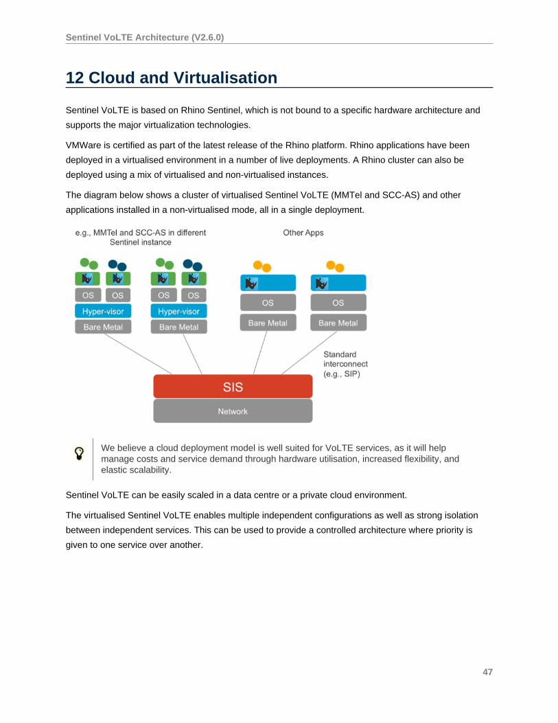
The diagram below shows a cluster of virtualised Sentinel VoLTE (MMTel and SCC-AS) and other
applications installed in a non-virtualised mode, all in a single deployment.
We believe a cloud deployment model is well suited for VoLTE services, as it will helpmanage costs and service demand through hardware utilisation, increased flexibility, andelastic scalability.
Sentinel VoLTE can be easily scaled in a data centre or a private cloud environment.
The virtualised Sentinel VoLTE enables multiple independent configurations as well as strong isolation
between independent services. This can be used to provide a controlled architecture where priority is
given to one service over another.
47
Sentinel VoLTE Architecture (V2.6.0)
13 XCAP Support
Sentinel VoLTE includes the following features to support XCAP.
See also the XCAP Query Examples on page 51 .
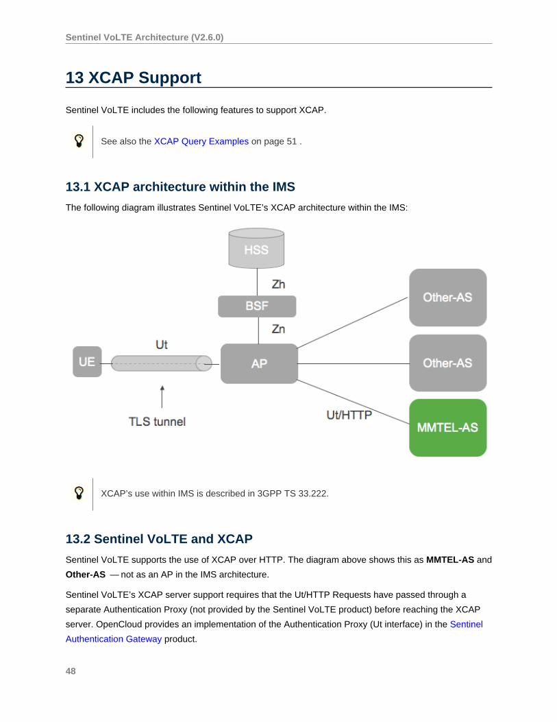
13.1 XCAP architecture within the IMS
The following diagram illustrates Sentinel VoLTE’s XCAP architecture within the IMS:
XCAP’s use within IMS is described in 3GPP TS 33.222.
13.2 Sentinel VoLTE and XCAP
Sentinel VoLTE supports the use of XCAP over HTTP. The diagram above shows this as MMTEL-AS and
Other-AS — not as an AP in the IMS architecture.
Sentinel VoLTE’s XCAP server support requires that the Ut/HTTP Requests have passed through a
separate Authentication Proxy (not provided by the Sentinel VoLTE product) before reaching the XCAP
server. OpenCloud provides an implementation of the Authentication Proxy (Ut interface) in the Sentinel
Authentication Gateway product.
48
Sentinel VoLTE Architecture (V2.6.0)
13.2.1 HTTP URIs and XCAP
Rhino VoLTE’s XCAP server runs alongside other HTTP servers. So it does not run on the “root URI” of a
server; rather, it runs on a URI relative to the root URI.
For example, if the XCAP Server is running on xcap.server.net with port 8080, the base XCAP URL will
be
http://xcap.server.net:8080/rem/sentinel/xcap.
The IMS XCAP standards place the XCAP URI at the root of the host. This means URI re-writing may be
required before hitting Sentinel VoLTE’s XCAP server.
This could be done via the AP, or via an HTTP proxy or web-server (such as Apache Web Server)
between the AP and Sentinel VoLTE’s XCAP server.
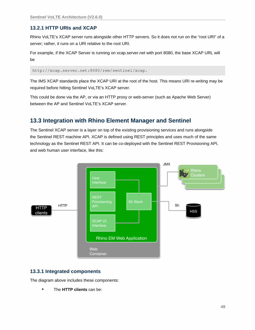
13.3 Integration with Rhino Element Manager and Sentinel
The Sentinel XCAP server is a layer on top of the existing provisioning services and runs alongside
the Sentinel REST machine API. XCAP is defined using REST principles and uses much of the same
technology as the Sentinel REST API. It can be co-deployed with the Sentinel REST Provisioning API,
and web human user interface, like this:
13.3.1 Integrated components
The diagram above includes these components:
• The HTTP clients can be:
49
Sentinel VoLTE Architecture (V2.6.0)
• a web browser
• a provisioning application
• an XCAP client (such as XCAP-enabled user equipment connecting through an
aggregation proxy).
• The HTTP servlet container configuration is used to specify the IP interfaces and port
numbers that the REM Web application is running on. Therefore, if the port that the REM
application is running on is to be reconfigured, the HTTP servlet container needs restarting.
• The REM web application is packaged as a web archive (WAR). It can be deployed into
various HTTP servlet containers. OpenCloud tests the application in Apache Tomcat and
Jetty HTTP servlet containers.
• The three HTTP-triggered components (web user interface, REST Provisioning API,
and XCAP server) are triggered from the same port. The HTTP Request URI is used to
distinguish which component processes a certain request.
Each of the components has their own security configuration.
13.3.2 Diameter Sh stacks and Rhino clusters
Each REM application includes one or more instances of the Diameter Sh stack . Each instance is
scoped to the Rhino cluster it is associated with. The Rhino cluster is selected when the REM user
selects a “Rhino instance” to log into.
Each instance of the Diameter Sh stack has Diameter peer configuration — including Realm tables for
multiple Destination Realms. In other words, a single Diameter stack instance can be configured to
connect to more than one distinct HSS.
Each instance of the Diameter Sh stack is shared by both the XCAP server and parts of the web user
interface.
Each Rhino cluster has connectivity to various systems. (That connectivity is not shown in the diagram
above.)
50
Sentinel VoLTE Architecture (V2.6.0)
14 XCAP Query Examples
Below are examples of XCAP queries with Sentinel VoLTE.
These examples assume that the XCAP Server is running on localhost with port 8090.
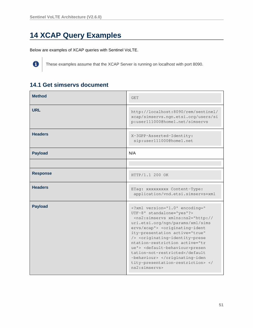
14.1 Get simservs document
Method GET
URL http://localhost:8090/rem/sentinel/xcap/simservs.ngn.etsi.org/users/sip:[email protected]/simservs
Headers X-3GPP-Asserted-Identity: sip:[email protected]
Payload N/A
Response HTTP/1.1 200 OK
Headers ETag: xxxxxxxxx Content-Type: application/vnd.etsi.simservs+xml
Payload <?xml version="1.0" encoding="UTF-8" standalone="yes"?> <ns2:simservs xmlns:ns2="http://uri.etsi.org/ngn/params/xml/simservs/xcap"> <originating-identity-presentation active="true"/> <originating-identity-presentation-restriction active="true"> <default-behaviour>presentation-not-restricted</default-behaviour> </originating-identity-presentation-restriction> </ns2:simservs>
51
Sentinel VoLTE Architecture (V2.6.0)
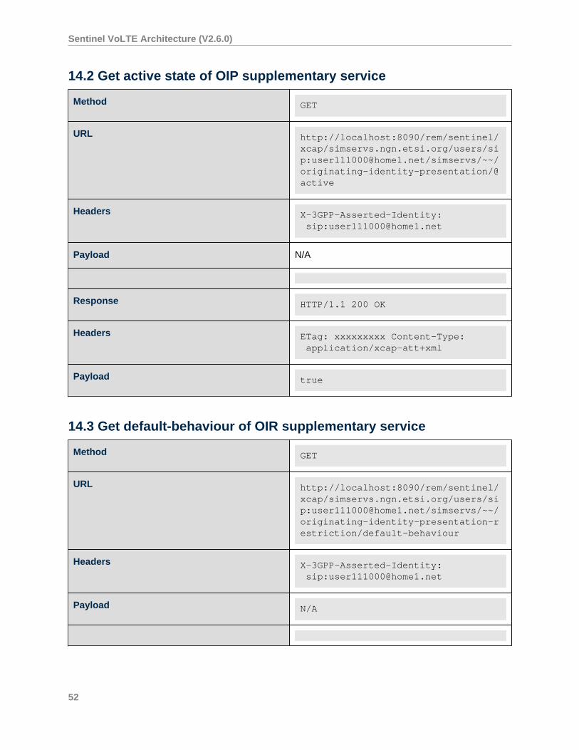
14.2 Get active state of OIP supplementary service
Method GET
URL http://localhost:8090/rem/sentinel/xcap/simservs.ngn.etsi.org/users/sip:[email protected]/simservs/~~/originating-identity-presentation/@active
Headers X-3GPP-Asserted-Identity: sip:[email protected]
Payload N/A
Response HTTP/1.1 200 OK
Headers ETag: xxxxxxxxx Content-Type: application/xcap-att+xml
Payload true
14.3 Get default-behaviour of OIR supplementary service
Method GET
URL http://localhost:8090/rem/sentinel/xcap/simservs.ngn.etsi.org/users/sip:[email protected]/simservs/~~/originating-identity-presentation-restriction/default-behaviour
Headers X-3GPP-Asserted-Identity: sip:[email protected]
Payload N/A
52
Sentinel VoLTE Architecture (V2.6.0)
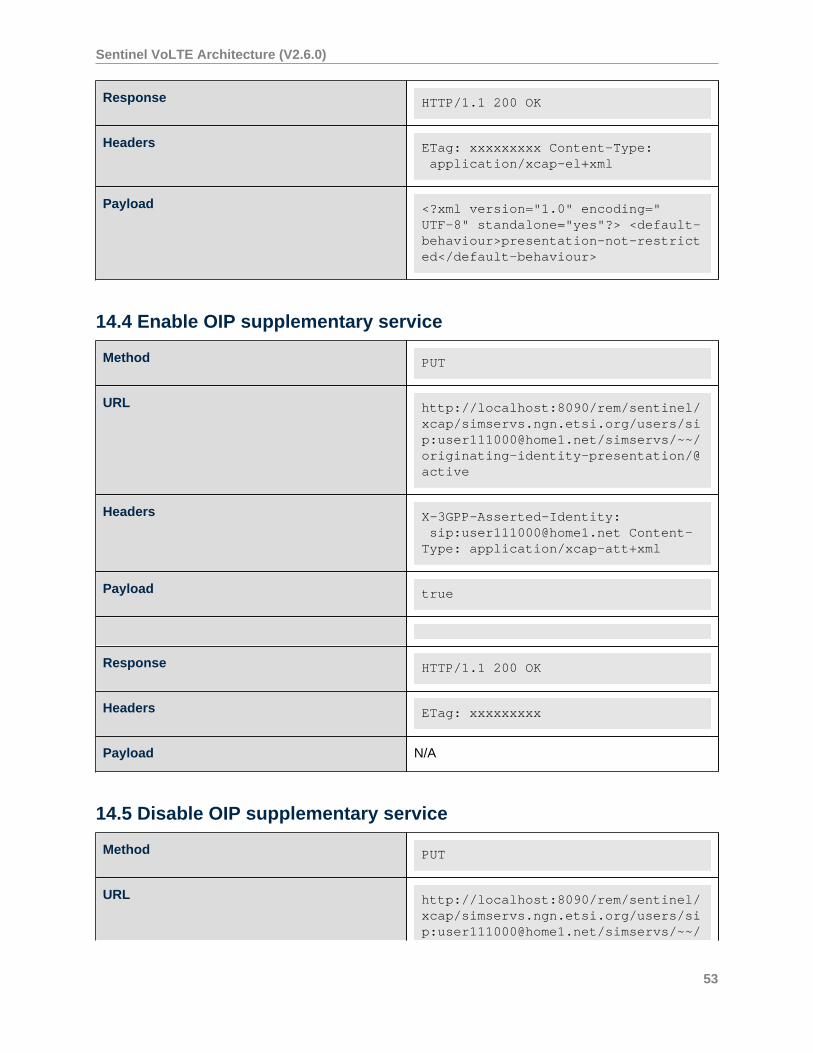
Response HTTP/1.1 200 OK
Headers ETag: xxxxxxxxx Content-Type: application/xcap-el+xml
Payload <?xml version="1.0" encoding="UTF-8" standalone="yes"?> <default-behaviour>presentation-not-restricted</default-behaviour>
14.4 Enable OIP supplementary service
Method PUT
URL http://localhost:8090/rem/sentinel/xcap/simservs.ngn.etsi.org/users/sip:[email protected]/simservs/~~/originating-identity-presentation/@active
Headers X-3GPP-Asserted-Identity: sip:[email protected] Content-Type: application/xcap-att+xml
Payload true
Response HTTP/1.1 200 OK
Headers ETag: xxxxxxxxx
Payload N/A
14.5 Disable OIP supplementary service
Method PUT
URL http://localhost:8090/rem/sentinel/xcap/simservs.ngn.etsi.org/users/sip:[email protected]/simservs/~~/
53
Sentinel VoLTE Architecture (V2.6.0)
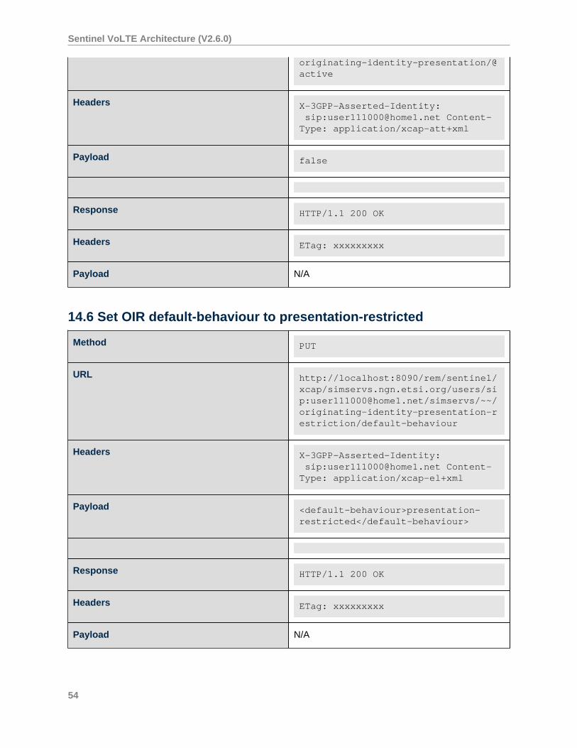
originating-identity-presentation/@active
Headers X-3GPP-Asserted-Identity: sip:[email protected] Content-Type: application/xcap-att+xml
Payload false
Response HTTP/1.1 200 OK
Headers ETag: xxxxxxxxx
Payload N/A
14.6 Set OIR default-behaviour to presentation-restricted
Method PUT
URL http://localhost:8090/rem/sentinel/xcap/simservs.ngn.etsi.org/users/sip:[email protected]/simservs/~~/originating-identity-presentation-restriction/default-behaviour
Headers X-3GPP-Asserted-Identity: sip:[email protected] Content-Type: application/xcap-el+xml
Payload <default-behaviour>presentation-restricted</default-behaviour>
Response HTTP/1.1 200 OK
Headers ETag: xxxxxxxxx
Payload N/A
54
Sentinel VoLTE Architecture (V2.6.0)
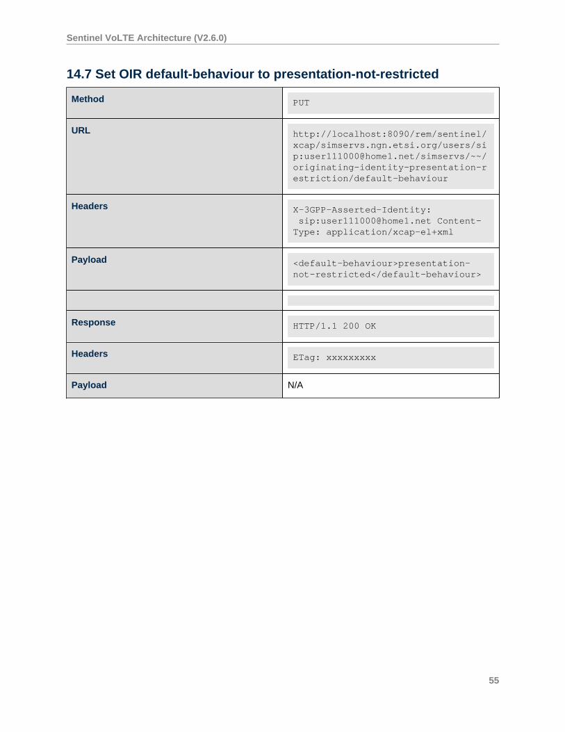
14.7 Set OIR default-behaviour to presentation-not-restricted
Method PUT
URL http://localhost:8090/rem/sentinel/xcap/simservs.ngn.etsi.org/users/sip:[email protected]/simservs/~~/originating-identity-presentation-restriction/default-behaviour
Headers X-3GPP-Asserted-Identity: sip:[email protected] Content-Type: application/xcap-el+xml
Payload <default-behaviour>presentation-not-restricted</default-behaviour>
Response HTTP/1.1 200 OK
Headers ETag: xxxxxxxxx
Payload N/A
55
Sentinel VoLTE Architecture (V2.6.0)
15 Instance Architecture for Sentinel VoLTE
Features of the instance architecture of the Sentinel VoLTE include:
• iFC triggering chaining and the SCC and MMTEL on page 56
• Co-location using the Rhino SIS on page 57
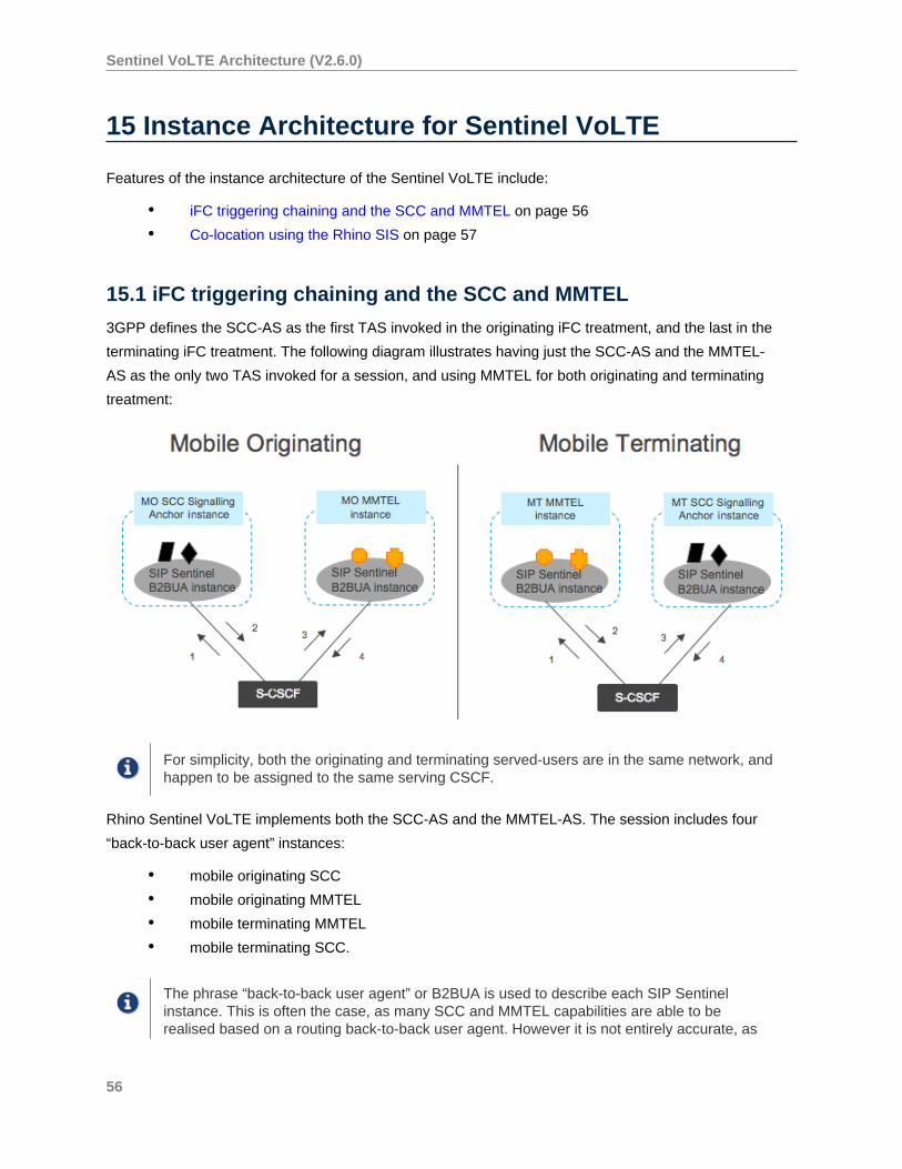
15.1 iFC triggering chaining and the SCC and MMTEL
3GPP defines the SCC-AS as the first TAS invoked in the originating iFC treatment, and the last in the
terminating iFC treatment. The following diagram illustrates having just the SCC-AS and the MMTEL-
AS as the only two TAS invoked for a session, and using MMTEL for both originating and terminating
treatment:
For simplicity, both the originating and terminating served-users are in the same network, andhappen to be assigned to the same serving CSCF.
Rhino Sentinel VoLTE implements both the SCC-AS and the MMTEL-AS. The session includes four
“back-to-back user agent” instances:
• mobile originating SCC
• mobile originating MMTEL
• mobile terminating MMTEL
• mobile terminating SCC.
The phrase “back-to-back user agent” or B2BUA is used to describe each SIP Sentinelinstance. This is often the case, as many SCC and MMTEL capabilities are able to berealised based on a routing back-to-back user agent. However it is not entirely accurate, as
56
Sentinel VoLTE Architecture (V2.6.0)
various capabilities, such as Access Transfer and MMTEL conferencing, require a much moresophisticated structure than a “Routing B2BUA”.
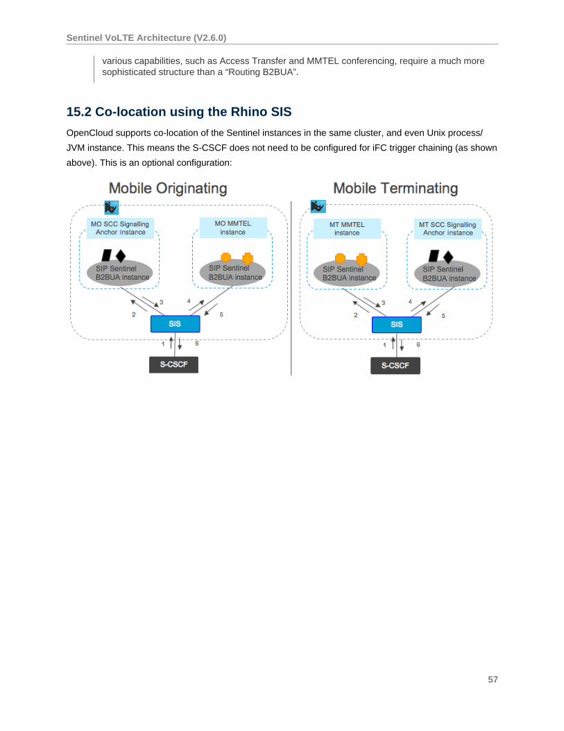
15.2 Co-location using the Rhino SIS
OpenCloud supports co-location of the Sentinel instances in the same cluster, and even Unix process/
JVM instance. This means the S-CSCF does not need to be configured for iFC trigger chaining (as shown
above). This is an optional configuration:
57
Sentinel VoLTE Architecture (V2.6.0)
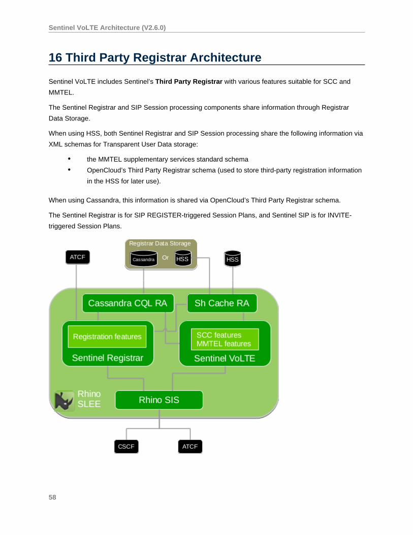
16 Third Party Registrar Architecture
Sentinel VoLTE includes Sentinel’s Third Party Registrar with various features suitable for SCC and
MMTEL.
The Sentinel Registrar and SIP Session processing components share information through Registrar
Data Storage.
When using HSS, both Sentinel Registrar and SIP Session processing share the following information via
XML schemas for Transparent User Data storage:
• the MMTEL supplementary services standard schema
• OpenCloud’s Third Party Registrar schema (used to store third-party registration information
in the HSS for later use).
When using Cassandra, this information is shared via OpenCloud’s Third Party Registrar schema.
The Sentinel Registrar is for SIP REGISTER-triggered Session Plans, and Sentinel SIP is for INVITE-
triggered Session Plans.
58
Sentinel VoLTE Architecture (V2.6.0)
The Third Party Registrar includes a feature that accesses the ATCF for 3GPP Release 10 Enhanced
SR-VCC.
Both the Third Party Registrar and Sentinel SIP Features use the Sh Cache RA to access the HSS or
Cassandra CQL RA to access the Cassandra database.
For more information, see Sentinel Registrar Overview and Concepts documentation .
59
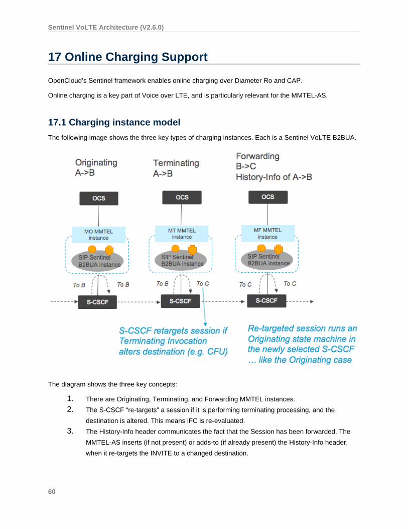
Sentinel VoLTE Architecture (V2.6.0)
17 Online Charging Support
OpenCloud’s Sentinel framework enables online charging over Diameter Ro and CAP.
Online charging is a key part of Voice over LTE, and is particularly relevant for the MMTEL-AS.
17.1 Charging instance model
The following image shows the three key types of charging instances. Each is a Sentinel VoLTE B2BUA.
The diagram shows the three key concepts:
1. There are Originating, Terminating, and Forwarding MMTEL instances.
2. The S-CSCF “re-targets” a session if it is performing terminating processing, and the
destination is altered. This means iFC is re-evaluated.
3. The History-Info header communicates the fact that the Session has been forwarded. The
MMTEL-AS inserts (if not present) or adds-to (if already present) the History-Info header,
when it re-targets the INVITE to a changed destination.
60
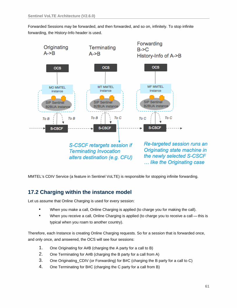
Sentinel VoLTE Architecture (V2.6.0)
Forwarded Sessions may be forwarded, and then forwarded, and so on, infinitely. To stop infinite
forwarding, the History-Info header is used.
MMTEL’s CDIV Service (a feature in Sentinel VoLTE) is responsible for stopping infinite forwarding.
17.2 Charging within the instance model
Let us assume that Online Charging is used for every session:
• When you make a call, Online Charging is applied (to charge you for making the call).
• When you receive a call, Online Charging is applied (to charge you to receive a call — this is
typical when you roam to another country).
Therefore, each Instance is creating Online Charging requests. So for a session that is forwarded once,
and only once, and answered, the OCS will see four sessions:
1. One Originating for A#B (charging the A party for a call to B)
2. One Terminating for A#B (charging the B party for a call from A)
3. One Originating_CDIV (or Forwarding) for B#C (charging the B party for a call to C)
4. One Terminating for B#C (charging the C party for a call from B)
61
Sentinel VoLTE Architecture (V2.6.0)
In the Terminating case — typically if the B party is not roaming — then the B party is often not charged.
In order to disable Online Charging for the B-parties Terminating Instance (for example, when not
roaming), you can:
• return the Online Charging System “credit control not applicable”, or
• disable the Sentinel Session Plan Online Charging (in the terminating and not-roaming case)
or
• both of the above approaches.
All instances within a network can be tied to the same “real world session” through the IMS Charging
Identifier (ICID).
17.3 SDP and charging
Under the SIP protocol, media streams may be added and removed, as well as having their codecs
changed.
When codecs change, Sentinel may consult its SDP codec configuration to determine if the change was a
“meaningful” change from a charging perspective.
• If a change is deemed meaningful, then Sentinel will perform client initiated re-authorization
towards the Online Charging System.
• If a change is not meaningful, then the current credit reservation remains.
Below is a screen showing Sentinel VoLTE’s default codec configuration:
62
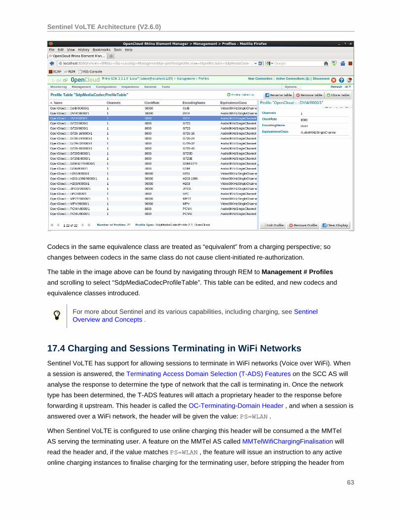
Sentinel VoLTE Architecture (V2.6.0)
Codecs in the same equivalence class are treated as “equivalent” from a charging perspective; so
changes between codecs in the same class do not cause client-initiated re-authorization.
The table in the image above can be found by navigating through REM to Management # Profiles
and scrolling to select “SdpMediaCodecProfileTable”. This table can be edited, and new codecs and
equivalence classes introduced.
For more about Sentinel and its various capabilities, including charging, see SentinelOverview and Concepts .
17.4 Charging and Sessions Terminating in WiFi Networks
Sentinel VoLTE has support for allowing sessions to terminate in WiFi networks (Voice over WiFi). When
a session is answered, the Terminating Access Domain Selection (T-ADS) Features on the SCC AS will
analyse the response to determine the type of network that the call is terminating in. Once the network
type has been determined, the T-ADS features will attach a proprietary header to the response before
forwarding it upstream. This header is called the OC-Terminating-Domain Header , and when a session is
answered over a WiFi network, the header will be given the value: PS=WLAN .
When Sentinel VoLTE is configured to use online charging this header will be consumed a the MMTel
AS serving the terminating user. A feature on the MMTel AS called MMTelWifiChargingFinalisation will
read the header and, if the value matches PS=WLAN , the feature will issue an instruction to any active
online charging instances to finalise charging for the terminating user, before stripping the header from
63
Sentinel VoLTE Architecture (V2.6.0)
the upstream forwarded response. When Sentinel VoLTE is not configured to use online charging, the
header will not be stripped by the MMTel AS. This allows it to be read by upstream charging functions.
The IM-SSF contains support for the OC-Terminating-Domain header. It terminates the IN dialog towards
the Prepaid SCP if it is processing a terminating session, and the terminating 2xx response to the INVITE
contains the OC-Terminating-Domain header with value PS=WLAN . In this case it strips the header before
forwarding the 2xx response upstream.
17.5 Population of AVPs on the Diameter Ro interface
The AVPs that are populated on the Diameter Ro interface are documented on the Ro Interface AVPs
section of the Sentinel VoLTE Administration guide.
64
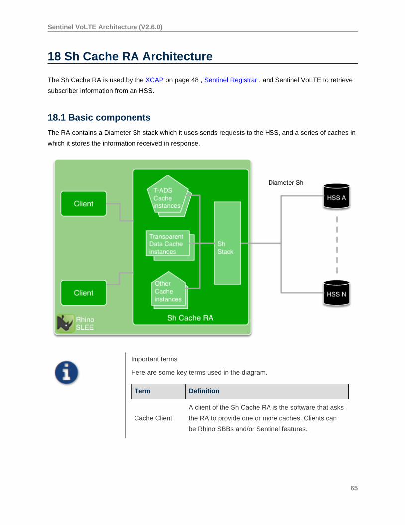
Sentinel VoLTE Architecture (V2.6.0)
18 Sh Cache RA Architecture
The Sh Cache RA is used by the XCAP on page 48 , Sentinel Registrar , and Sentinel VoLTE to retrieve
subscriber information from an HSS.
18.1 Basic components
The RA contains a Diameter Sh stack which it uses sends requests to the HSS, and a series of caches in
which it stores the information received in response.
Important terms
Here are some key terms used in the diagram.
Term Definition
Cache Client
A client of the Sh Cache RA is the software that asks
the RA to provide one or more caches. Clients can
be Rhino SBBs and/or Sentinel features.
65
Sentinel VoLTE Architecture (V2.6.0)
Non-transp
arent Data
Non-transparent data as defined in the Diameter Sh
protocol (such as IMS User State, MSISDN, or IMS
Public Identity).
Transparent
Data
User-specified data that is transmitted over Diameter
Sh protocol.
Service
Indication
A string used to identify a specific type of transparent
data (such as MMTel-Services).
18.1.1 Basic cache RA function
When a cache client requires a piece of information for a given subscriber, it must ask the RA to provide
it with the appropriate cache instance for that type of information. The client then queries the cache
directly. If the cache already contains the requested information ,it can provide it immediately. If it does
not have the information, the cache will request the information from the appropriate HSS. When the data
is received from the HSS,the cache will automatically store the information and then provide it back to the
original requesting client.
The precise behaviour of a given cache instance is determined by its cache configuration. This
configuration determines how and when to use data within the cache and when to request information
from the HSS.
18.1.2 Cache instances and types
The Sh Cache RA holds many cache instances. These caches are contained within the JVM heap.
Instances are created on demand through an API. At creation each cache is provided with a configuration
that defines its caching behaviour.
Each cache instance has a specific type corresponding to the type of data contained within the cache
instance. These cache types fall into one of two categories:
• non-transparent data caches correspond to the non-transparent data fields defined in
the Sh protocolm where there is a cache type built into the Sh Cache RA for each of the
available fields. Each non-transparent cache contains a single value type — this is a Java
type that is directly mapped to the Sh protocol description.
• transparent data cache types are defined by the clients using the Sh Cache RA. Each
transparent data cache corresponds to a particular service indication as defined by the client.
The appropriate codec and Java type for the cache data must be provided by the client.
Each transparent cache stores the XML document (a DOM element) and is templated on the
Java type for this element, as well as the current sequence number for that Document. So
transparent data caches are “document caches”.
66
Sentinel VoLTE Architecture (V2.6.0)
Transparent data caches require a codec to convert their data between an XML document
and its associated Java type. There are many different frameworks available for use of XML
within Java. We have chosen JAXB for our Sh Cache RA, and therefore we also chose JAXB
for the MMTEL services codec; however, there is nothing to prevent the choice of DOM,
Apache JDOM, or any other framework instead of JAXB.
18.1.3 Cache configuration
Clients provide a cache configuration when asking for a cache. Each cache configuration corresponds
directly to a cache instance within the RA. The first call to the RA with a given configuration will result in a
new cache being created with that configuration. Subsequent calls to the RA with the same configuration
will retrieve the already extisting instance for that configuration. Clients can ask the RA to provide a
default configuration for each non-transparent cache type.
All cache configurations contain the following information:
• the Diameter destination host and destination realm for the HSS that is to be used by the
cache instance (different cache instances may interact with different HSSs)
• the Cache Retention Strategy, which includes:
• the basic caching strategy (no caching, cache with time-based eviction, cache with
size-based eviction)
• whether or not to subscribe to updates
• size and time parameters for the basic strategy.
Transparent data cache configurations also include:
• the Service Indication of the transparent data.
18.2 Diameter and Diameter Sh use
The Sh Cache RA embeds the OpenCloud Diameter Stack, and the Sh Protocol API. None of the Sh
protocol “efficiency” features are used by the RA. When a client asks the Sh Cache RA for some data,
the RA will check the cache for the data; if the data is not present, the RA will perform a single Sh query
to the HSS for the data. The Sh Cache RA will not ask the HSS for multiple items within the same Sh
request.
Diameter Peer and peer configuration in the Sh Cache RA works in the same way as other OpenCloud
Diameter RAs.
Therefore, an entity of the Sh Cache RA can connect to multiple discrete HSS.
18.2.1 Synchronous and asynchronous lookups
The Sh Cache RA supports both synchronous and asynchronous methods of retrieving and updating
information in the HSS:
67
Sentinel VoLTE Architecture (V2.6.0)
• Synchronous methods simply block the caller until the information retrieval/update is
complete. This means that if the request requires communication with the HSS, the client is
forced to wait until the Sh transaction is complete before doing anything else.
• Asynchronous methods are non-blocking for retrieving and updating information. They use
SLEE events to alert the client when their transaction is complete.
18.3 The Sh cache RA in VoLTE
The Sh Cache RA is used by Sentinel VoLTE for all of its interactions with an HSS over the Diameter Sh
protocol. The Sh Cache RA provides configurable caching functionality for any data requested from the
HSS. The main users of the Sh Cache RA within Sentinel VoLTE are the SCC features and the Sentinel
Registrar (our third-party registrar), which use the caches for Diameter Sh non-transparent data. The
MMTel features also store their subscriber-specific configuration data within Sh transparent data and
access it via the SubscriberDataLookupFromHSS feature.
18.4 Subscriber data lookup
In non-VoLTE versions of Sentinel there is a feature called SubscriberDataLookup that is used to
retrieve subscriber specific information and configuration. This version of SubscriberDataLookup
retrieves a row in an SQL database corresponding to a given subscriber and maps the columns in that
row to session state fields.
In Sentinel VoLTE, this feature has been replaced with the SubscriberDataLookupFromHSS feature.
This feature uses the HSS in place of an SQL database and retrieves data via Sh protocol through the Sh
Cache RA.
Sentinel VoLTE uses transparent data to store subscriber data for MMTel features in the HSS. This data
is accessed with the service indication “MMTEL-Services”. A codec that can convert the raw transparent
data from the HSS (stored as an XML document) into a Java object is provided by the feature.
The feature maps data in the resulting Java object to session state fields. The exact mapping
configuration is defined in a profile table.
It is also possible to configure the SubscriberDataLookupFromHSS to retrieve other kinds of transparent
data through a profile table.
Details for how the SubscriberDataLookupFromHSS feature is configured can be found on the
SubscriberDataLookupFromHSS feature page in the Sentinel VoLTE administration guide.
18.4.1 Non-transparent data use
Various SCC features depend on non-transparent user data, either directly, or through the Sentinel
Registrar. These features generally depend on the default cache configuration for the particular kind of
data they are interested in. See the Sentinel Volte Administration Guide for more details.
68
Sentinel VoLTE Architecture (V2.6.0)
18.4.2 Multi-tenancy within the cache
The network operator portion of the Sentinel selection key is used as part of the Sh Cache Configuration
object.
This means that each Network Operator’s data is stored in different cache instances within the RA.
69
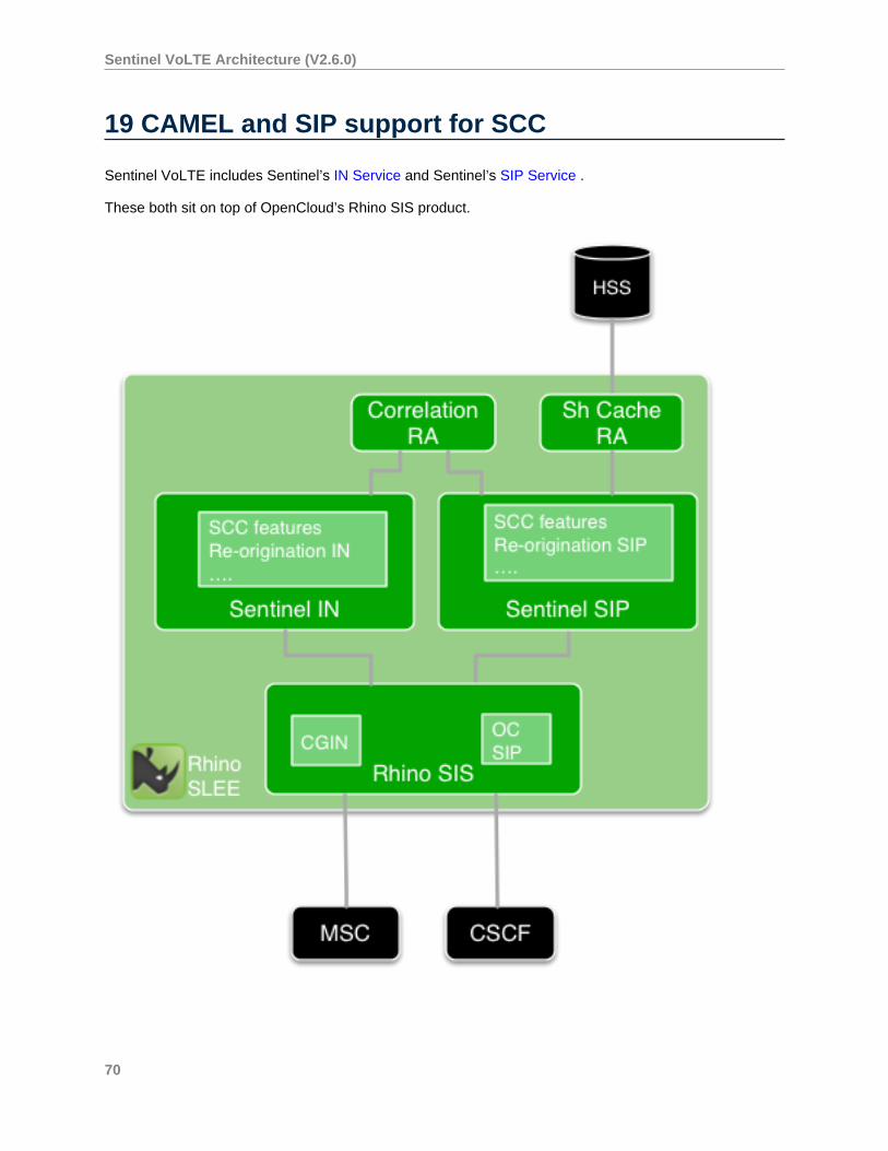
Sentinel VoLTE Architecture (V2.6.0)
19 CAMEL and SIP support for SCC
Sentinel VoLTE includes Sentinel’s IN Service and Sentinel’s SIP Service .
These both sit on top of OpenCloud’s Rhino SIS product.
70
Sentinel VoLTE Architecture (V2.6.0)
These services each contain features for IMS Service Centralisation. Of note are the Re-origination
features. One sits in the Sentinel IN service, and the other in the Sentinel SIP service. Re-origination data
is stored in the Correlation RA.
More information on these features is described in the VoLTE Administration Guide, under the Service
Centralisation Features .
71
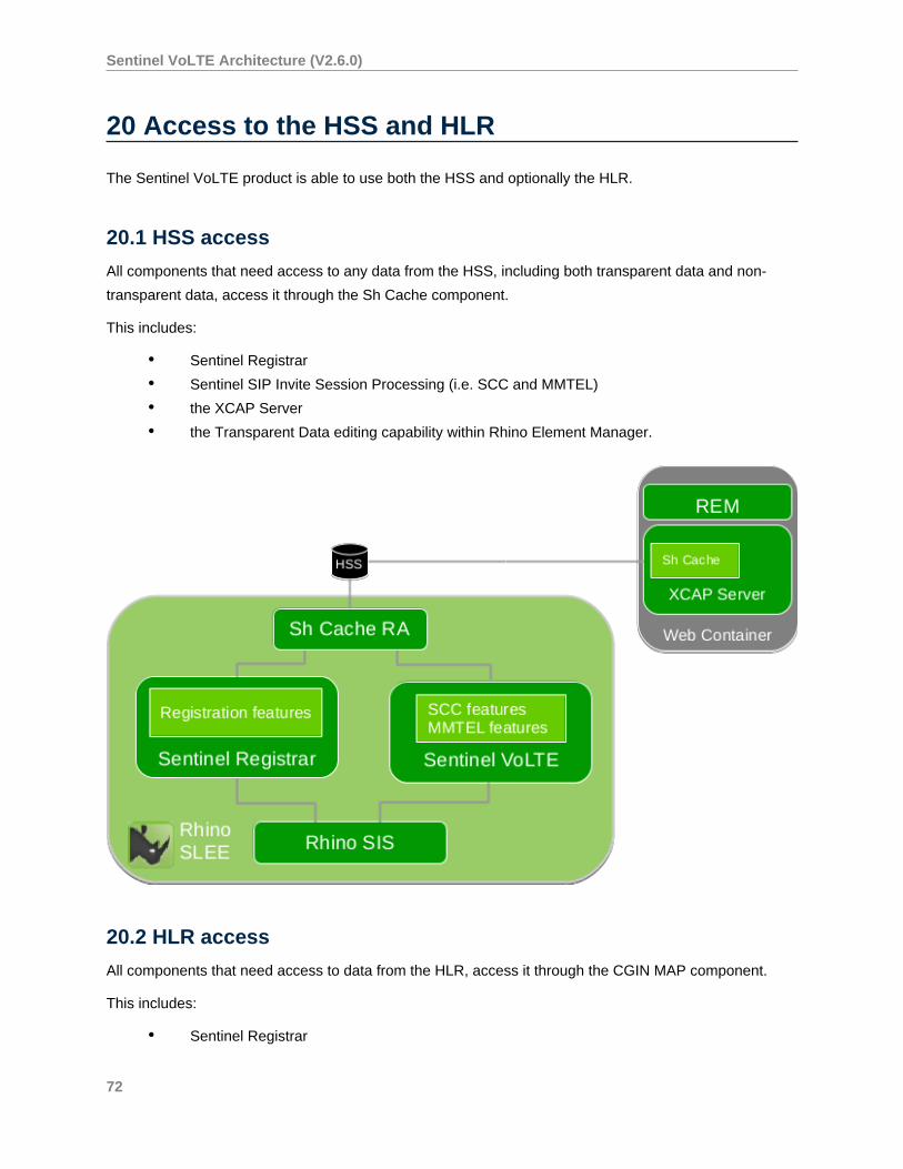
Sentinel VoLTE Architecture (V2.6.0)
20 Access to the HSS and HLR
The Sentinel VoLTE product is able to use both the HSS and optionally the HLR.
20.1 HSS access
All components that need access to any data from the HSS, including both transparent data and non-
transparent data, access it through the Sh Cache component.
This includes:
• Sentinel Registrar
• Sentinel SIP Invite Session Processing (i.e. SCC and MMTEL)
• the XCAP Server
• the Transparent Data editing capability within Rhino Element Manager.
20.2 HLR access
All components that need access to data from the HLR, access it through the CGIN MAP component.
This includes:
• Sentinel Registrar
72
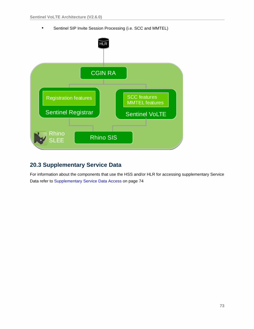
Sentinel VoLTE Architecture (V2.6.0)
• Sentinel SIP Invite Session Processing (i.e. SCC and MMTEL)
20.3 Supplementary Service Data
For information about the components that use the HSS and/or HLR for accessing supplementary Service
Data refer to Supplementary Service Data Access on page 74
73
Sentinel VoLTE Architecture (V2.6.0)
21 Supplementary Service Data Access
All standardised Supplementary Service Data is located in either the HLR (for GSM networks) and/or the
HSS (for IMS networks), and/or in a convergent HLR/HSS.
When accessing Supplementary Service Data from the HSS, the Diameter Sh interface is used. The
Supplementary Service Data is stored according to standardized XML schemas within Transparent User
Data.
When accessing Supplementary Service Data in the HLR, the GSM MAP protocol is used.
Supplementary Service Data is stored according to standardized schemas (often ASN.1 defined).
21.1 Supplementary Service Data stored in the HSS
All components that need access to any data from the HSS, including both Transparent and Non-
transparent data, access it through the Sh Cache component. Components that use Supplementary
Service Data in the HSS include:
Component Name Purpose
Sentinel Registrar Cache warming of the Served User’s
Supplementary Service Data upon Initial
Registration
Sentinel VoLTE MMTel Features Supplementary Service Data is necessary for
many features to operate
XCAP Server The purpose of the XCAP server is to enable
subscribers to query and modify their service
settings
Transparent Data editing capability within the
Rhino Element Manager
This capability enables an administrator to query
and edit the Supplementary Service Data
21.2 Supplementary Service Data stored in the HLR
All components that need access to data from the HLR, access it through the CGIN MAP component.
Components that use Supplementary Service Data in the HLR include:
• Sentinel VoLTE MMTel features - Supplementary Service Data is necessary for many
features to operate
74
Sentinel VoLTE Architecture (V2.6.0)
22 SDP conflict management
Sentinel VoLTE may need to manipulate SDP (Session Description Protocol — RFC 4566 ) content in
SIP message bodies to resolve conflicts. This section explains why SDP conflict management is required
in some cases, and how it is implemented in Sentinel VoLTE.
22.1 SDP conflict management overview
The Sentinel VoLTE SCC-AS may detect SDP conflicts when forwarding SDP between a pair of legs on
a session. This capability is currently only enabled in access transfer features. Other features may also
access it through the sentinel-sip-spi API, see Using SDP conflict management in a feature on
page 82 below.
Conflicts arise when there is an existing media session established, and the SCC-AS receives an SDP
offer from another source, that must replace the existing media. The new SDP offer must use the correct
session ID and version, as well as having the same number of media ( m= ) lines that the previous
offer had, otherwise the new offer will be rejected. If the new offer comes from a different entity to the
previous offer, then there will almost certainly be a conflict. This situation occurs in many access transfer
scenarios.
These are summarised from RFC 4566 and RFC 6337 , for reference.
• All SDP offers sent by a user agent in the same dialog must have the same session ID in the
origin ( o= ) line.
• An SDP offer that changes the session description must have a session version one greater
than the previous SDP offer.
• An SDP offer that does not change the session description must have the same session
version as the previous SDP offer.
• The order of media descriptions ( m= lines) is significant, it is used by UEs when comparing
with the previous SDP.
• Media descriptions can be added and changed, but never removed. To "remove" a media
description, leave it in place and set its port to zero.
• A disabled media description’s position can be reused in a later offer, using a different port
and codec etc.
The conflict management system is defined in terms of source and destination legs:
• The destination leg is the established leg between the SCC-AS and another entity, typically
a UE. A previous SDP offer has been sent on this leg, so all subsequent offers must follow
the same sequence of session ID and version, as well as matching the previous number of
media streams.
75
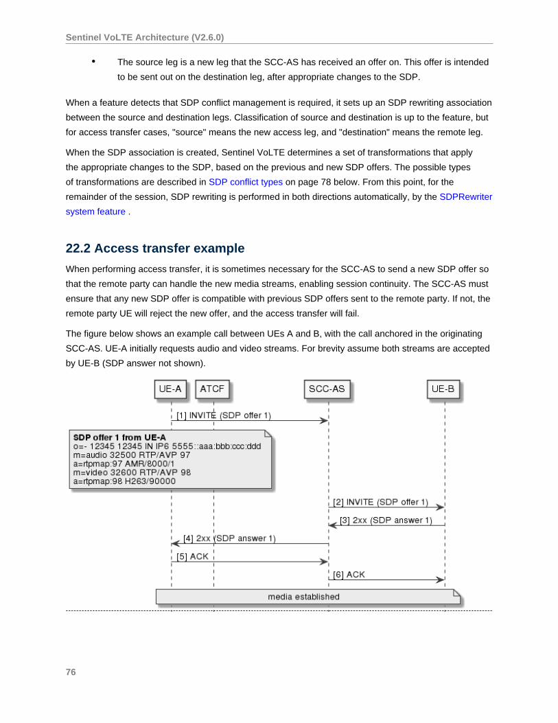
Sentinel VoLTE Architecture (V2.6.0)
• The source leg is a new leg that the SCC-AS has received an offer on. This offer is intended
to be sent out on the destination leg, after appropriate changes to the SDP.
When a feature detects that SDP conflict management is required, it sets up an SDP rewriting association
between the source and destination legs. Classification of source and destination is up to the feature, but
for access transfer cases, "source" means the new access leg, and "destination" means the remote leg.
When the SDP association is created, Sentinel VoLTE determines a set of transformations that apply
the appropriate changes to the SDP, based on the previous and new SDP offers. The possible types
of transformations are described in SDP conflict types on page 78 below. From this point, for the
remainder of the session, SDP rewriting is performed in both directions automatically, by the SDPRewriter
system feature .
22.2 Access transfer example
When performing access transfer, it is sometimes necessary for the SCC-AS to send a new SDP offer so
that the remote party can handle the new media streams, enabling session continuity. The SCC-AS must
ensure that any new SDP offer is compatible with previous SDP offers sent to the remote party. If not, the
remote party UE will reject the new offer, and the access transfer will fail.
The figure below shows an example call between UEs A and B, with the call anchored in the originating
SCC-AS. UE-A initially requests audio and video streams. For brevity assume both streams are accepted
by UE-B (SDP answer not shown).
76
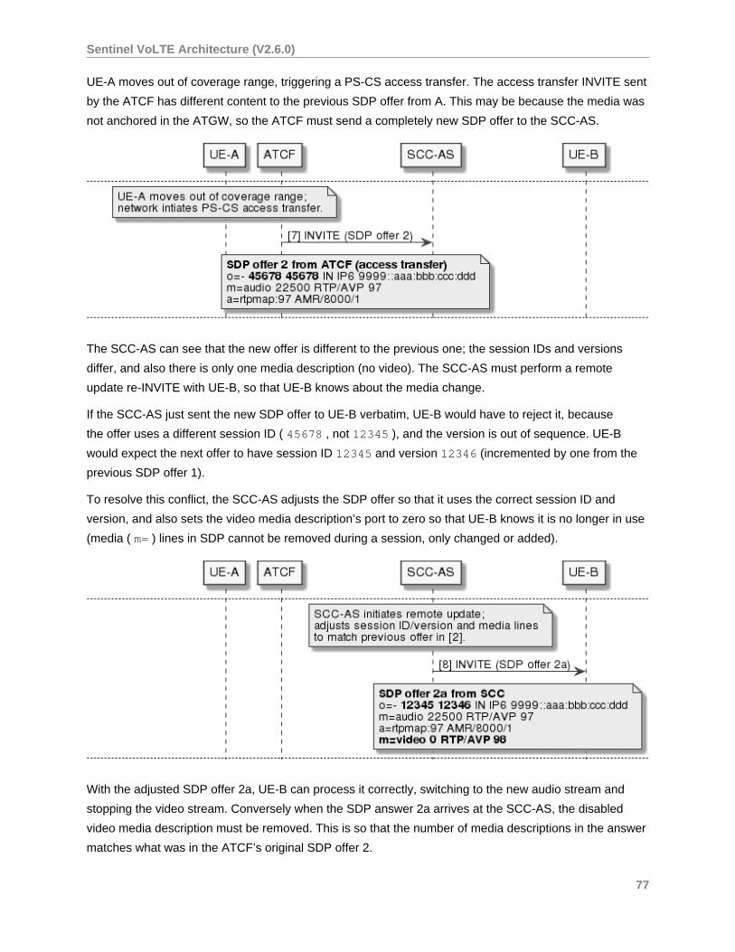
Sentinel VoLTE Architecture (V2.6.0)
UE-A moves out of coverage range, triggering a PS-CS access transfer. The access transfer INVITE sent
by the ATCF has different content to the previous SDP offer from A. This may be because the media was
not anchored in the ATGW, so the ATCF must send a completely new SDP offer to the SCC-AS.
The SCC-AS can see that the new offer is different to the previous one; the session IDs and versions
differ, and also there is only one media description (no video). The SCC-AS must perform a remote
update re-INVITE with UE-B, so that UE-B knows about the media change.
If the SCC-AS just sent the new SDP offer to UE-B verbatim, UE-B would have to reject it, because
the offer uses a different session ID ( 45678 , not 12345 ), and the version is out of sequence. UE-B
would expect the next offer to have session ID 12345 and version 12346 (incremented by one from the
previous SDP offer 1).
To resolve this conflict, the SCC-AS adjusts the SDP offer so that it uses the correct session ID and
version, and also sets the video media description’s port to zero so that UE-B knows it is no longer in use
(media ( m= ) lines in SDP cannot be removed during a session, only changed or added).
With the adjusted SDP offer 2a, UE-B can process it correctly, switching to the new audio stream and
stopping the video stream. Conversely when the SDP answer 2a arrives at the SCC-AS, the disabled
video media description must be removed. This is so that the number of media descriptions in the answer
matches what was in the ATCF’s original SDP offer 2.
77
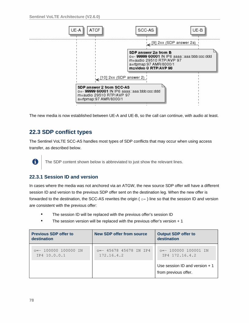
Sentinel VoLTE Architecture (V2.6.0)
The new media is now established between UE-A and UE-B, so the call can continue, with audio at least.
22.3 SDP conflict types
The Sentinel VoLTE SCC-AS handles most types of SDP conflicts that may occur when using access
transfer, as described below.
The SDP content shown below is abbreviated to just show the relevant lines.
22.3.1 Session ID and version
In cases where the media was not anchored via an ATGW, the new source SDP offer will have a different
session ID and version to the previous SDP offer sent on the destination leg. When the new offer is
forwarded to the destination, the SCC-AS rewrites the origin ( o= ) line so that the session ID and version
are consistent with the previous offer:
• The session ID will be replaced with the previous offer’s session ID
• The session version will be replaced with the previous offer’s version + 1
Previous SDP offer todestination
New SDP offer from source Output SDP offer todestination
o=- 100000 100000 IN IP4 10.0.0.1
o=- 45678 45678 IN IP4 172.16.4.2
o=- 100000 100001 IN IP4 172.16.4.2
Use session ID and version + 1
from previous offer.
78
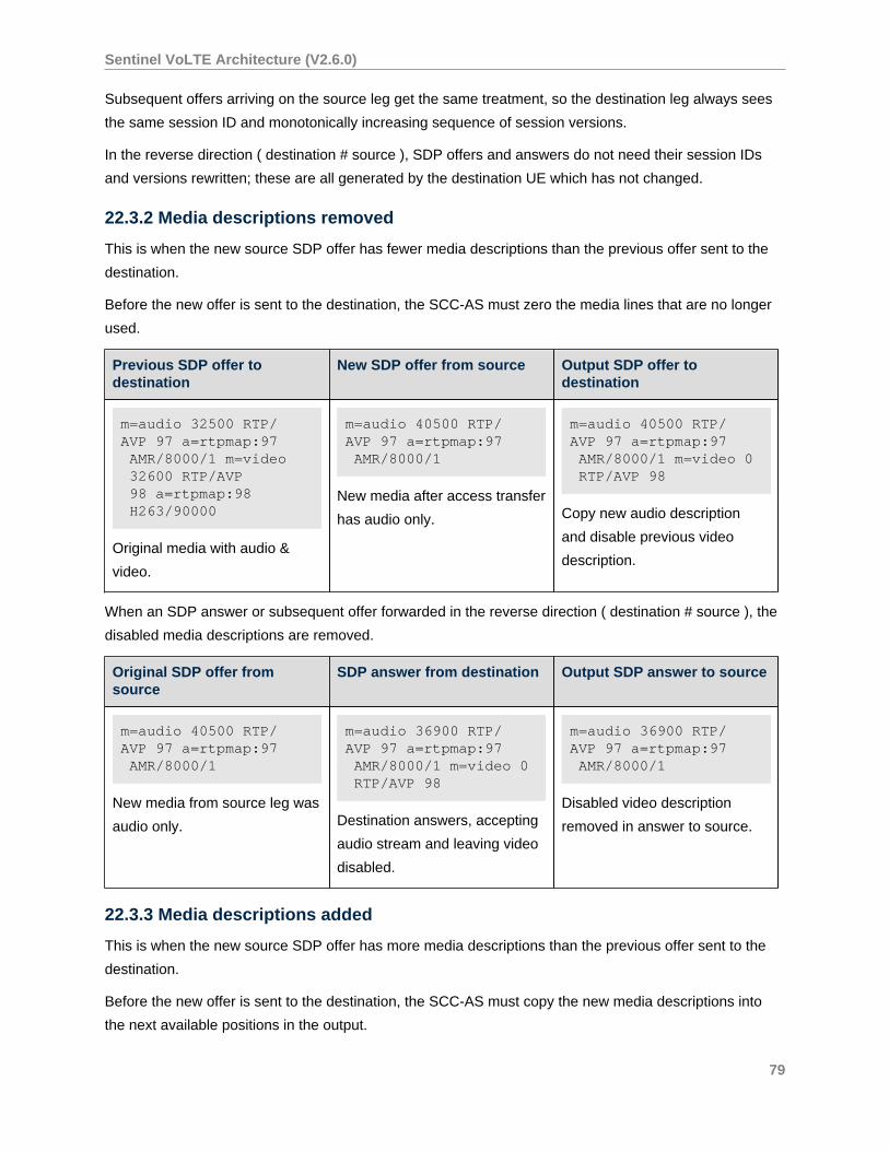
Sentinel VoLTE Architecture (V2.6.0)
Subsequent offers arriving on the source leg get the same treatment, so the destination leg always sees
the same session ID and monotonically increasing sequence of session versions.
In the reverse direction ( destination # source ), SDP offers and answers do not need their session IDs
and versions rewritten; these are all generated by the destination UE which has not changed.
22.3.2 Media descriptions removed
This is when the new source SDP offer has fewer media descriptions than the previous offer sent to the
destination.
Before the new offer is sent to the destination, the SCC-AS must zero the media lines that are no longer
used.
Previous SDP offer todestination
New SDP offer from source Output SDP offer todestination
m=audio 32500 RTP/AVP 97 a=rtpmap:97 AMR/8000/1 m=video 32600 RTP/AVP 98 a=rtpmap:98 H263/90000
Original media with audio &
video.
m=audio 40500 RTP/AVP 97 a=rtpmap:97 AMR/8000/1
New media after access transfer
has audio only.
m=audio 40500 RTP/AVP 97 a=rtpmap:97 AMR/8000/1 m=video 0 RTP/AVP 98
Copy new audio description
and disable previous video
description.
When an SDP answer or subsequent offer forwarded in the reverse direction ( destination # source ), the
disabled media descriptions are removed.
Original SDP offer fromsource
SDP answer from destination Output SDP answer to source
m=audio 40500 RTP/AVP 97 a=rtpmap:97 AMR/8000/1
New media from source leg was
audio only.
m=audio 36900 RTP/AVP 97 a=rtpmap:97 AMR/8000/1 m=video 0 RTP/AVP 98
Destination answers, accepting
audio stream and leaving video
disabled.
m=audio 36900 RTP/AVP 97 a=rtpmap:97 AMR/8000/1
Disabled video description
removed in answer to source.
22.3.3 Media descriptions added
This is when the new source SDP offer has more media descriptions than the previous offer sent to the
destination.
Before the new offer is sent to the destination, the SCC-AS must copy the new media descriptions into
the next available positions in the output.
79
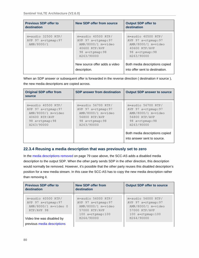
Sentinel VoLTE Architecture (V2.6.0)
Previous SDP offer todestination
New SDP offer from source Output SDP offer todestination
m=audio 32500 RTP/AVP 97 a=rtpmap:97 AMR/8000/1
m=audio 40500 RTP/AVP 97 a=rtpmap:97 AMR/8000/1 m=video 40600 RTP/AVP 98 a=rtpmap:98 H263/90000
New source offer adds a video
description.
m=audio 40500 RTP/AVP 97 a=rtpmap:97 AMR/8000/1 m=video 40600 RTP/AVP 98 a=rtpmap:98 H263/90000
Both media descriptions copied
into offer sent to destination.
When an SDP answer or subsequent offer is forwarded in the reverse direction ( destination # source ),
the new media descriptions are copied across.
Original SDP offer fromsource
SDP answer from destination Output SDP answer to source
m=audio 40500 RTP/AVP 97 a=rtpmap:97 AMR/8000/1 m=video 40600 RTP/AVP 98 a=rtpmap:98 H263/90000
m=audio 56700 RTP/AVP 97 a=rtpmap:97 AMR/8000/1 m=video 56800 RTP/AVP 98 a=rtpmap:98 H263/90000
m=audio 56700 RTP/AVP 97 a=rtpmap:97 AMR/8000/1 m=video 56800 RTP/AVP 98 a=rtpmap:98 H263/90000
Both media descriptions copied
into answer sent to source.
22.3.4 Reusing a media description that was previously set to zero
In the media descriptions removed on page 79 case above, the SCC-AS adds a disabled media
description to the output SDP. When the other party sends SDP in the other direction, this description
would normally be removed. However, it’s possible that the other party reuses this disabled description’s
position for a new media stream. In this case the SCC-AS has to copy the new media description rather
than removing it.
Previous SDP offer todestination
New SDP offer fromdestination
Output SDP offer to source
m=audio 40500 RTP/AVP 97 a=rtpmap:97 AMR/8000/1 m=video 0 RTP/AVP 98
Video line was disabled by
previous media descriptions
m=audio 56000 RTP/AVP 97 a=rtpmap:97 AMR/8000/1 m=video 57000 RTP/AVP 100 a=rtpmap:100 H264/90000
m=audio 56000 RTP/AVP 97 a=rtpmap:97 AMR/8000/1 m=video 57000 RTP/AVP 100 a=rtpmap:100 H264/90000
80
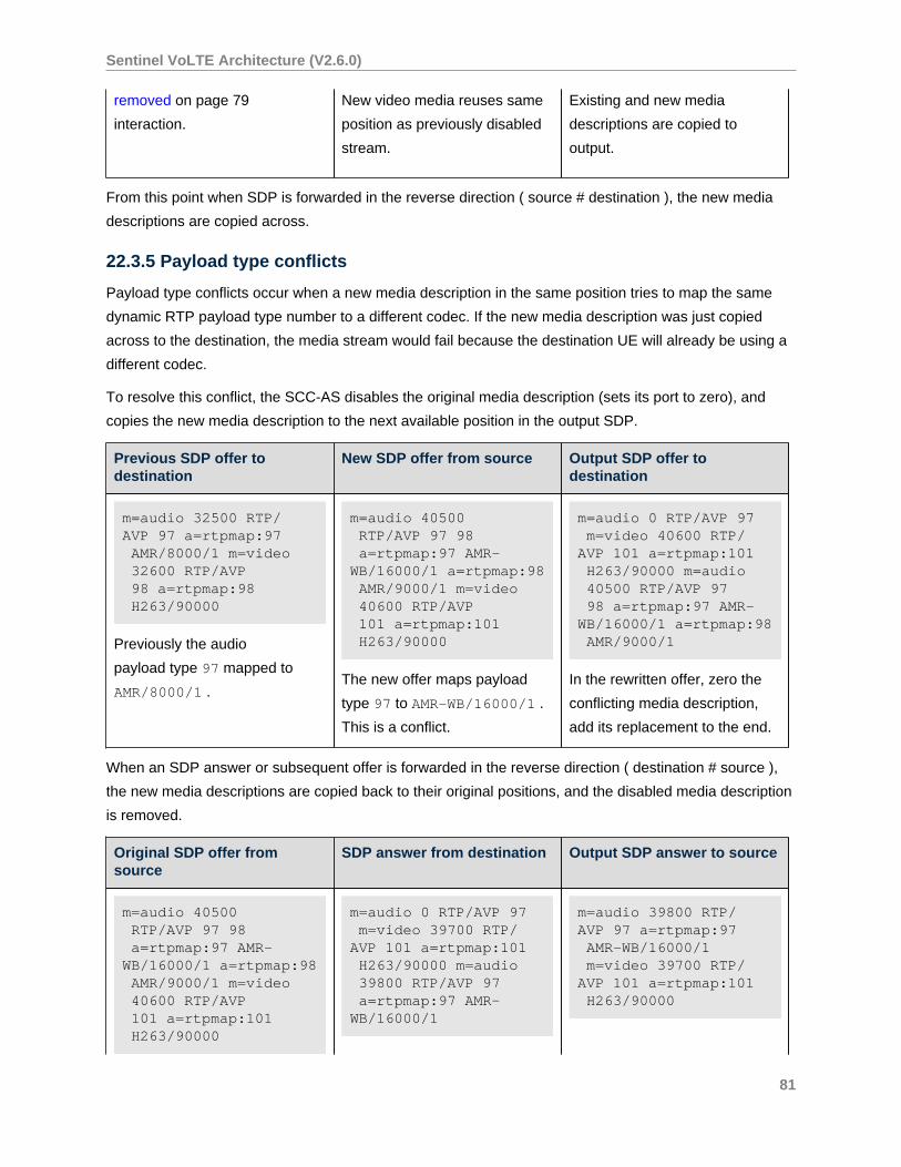
Sentinel VoLTE Architecture (V2.6.0)
removed on page 79
interaction.
New video media reuses same
position as previously disabled
stream.
Existing and new media
descriptions are copied to
output.
From this point when SDP is forwarded in the reverse direction ( source # destination ), the new media
descriptions are copied across.
22.3.5 Payload type conflicts
Payload type conflicts occur when a new media description in the same position tries to map the same
dynamic RTP payload type number to a different codec. If the new media description was just copied
across to the destination, the media stream would fail because the destination UE will already be using a
different codec.
To resolve this conflict, the SCC-AS disables the original media description (sets its port to zero), and
copies the new media description to the next available position in the output SDP.
Previous SDP offer todestination
New SDP offer from source Output SDP offer todestination
m=audio 32500 RTP/AVP 97 a=rtpmap:97 AMR/8000/1 m=video 32600 RTP/AVP 98 a=rtpmap:98 H263/90000
Previously the audio
payload type 97 mapped to
AMR/8000/1 .
m=audio 40500 RTP/AVP 97 98 a=rtpmap:97 AMR-WB/16000/1 a=rtpmap:98 AMR/9000/1 m=video 40600 RTP/AVP 101 a=rtpmap:101 H263/90000
The new offer maps payload
type 97 to AMR-WB/16000/1 .
This is a conflict.
m=audio 0 RTP/AVP 97 m=video 40600 RTP/AVP 101 a=rtpmap:101 H263/90000 m=audio 40500 RTP/AVP 97 98 a=rtpmap:97 AMR-WB/16000/1 a=rtpmap:98 AMR/9000/1
In the rewritten offer, zero the
conflicting media description,
add its replacement to the end.
When an SDP answer or subsequent offer is forwarded in the reverse direction ( destination # source ),
the new media descriptions are copied back to their original positions, and the disabled media description
is removed.
Original SDP offer fromsource
SDP answer from destination Output SDP answer to source
m=audio 40500 RTP/AVP 97 98 a=rtpmap:97 AMR-WB/16000/1 a=rtpmap:98 AMR/9000/1 m=video 40600 RTP/AVP 101 a=rtpmap:101 H263/90000
m=audio 0 RTP/AVP 97 m=video 39700 RTP/AVP 101 a=rtpmap:101 H263/90000 m=audio 39800 RTP/AVP 97 a=rtpmap:97 AMR-WB/16000/1
m=audio 39800 RTP/AVP 97 a=rtpmap:97 AMR-WB/16000/1 m=video 39700 RTP/AVP 101 a=rtpmap:101 H263/90000
81
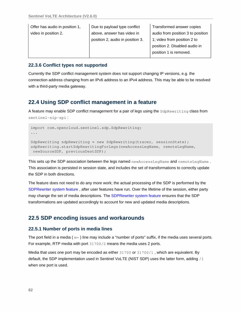
Sentinel VoLTE Architecture (V2.6.0)
Offer has audio in position 1,
video in position 2.
Due to payload type conflict
above, answer has video in
position 2, audio in position 3.
Transformed answer copies
audio from position 3 to position
1; video from position 2 to
position 2. Disabled audio in
position 1 is removed.
22.3.6 Conflict types not supported
Currently the SDP conflict management system does not support changing IP versions, e.g. the
connection address changing from an IPv6 address to an IPv4 address. This may be able to be resolved
with a third-party media gateway.
22.4 Using SDP conflict management in a feature
A feature may enable SDP conflict management for a pair of legs using the SdpRewriting class from
sentinel-sip-spi :
import com.opencloud.sentinel.sdp.SdpRewriting;...
SdpRewriting sdpRewriting = new SdpRewriting(tracer, sessionState);sdpRewriting.startSdpRewritingForLegs(newAccessLegName, remoteLegName, newSourceSDP, previousDestSDP);
This sets up the SDP association between the legs named newAccessLegName and remoteLegName .
This association is persisted in session state, and includes the set of transformations to correctly update
the SDP in both directions.
The feature does not need to do any more work; the actual processing of the SDP is performed by the
SDPRewriter system feature , after user features have run. Over the lifetime of the session, either party
may change the set of media descriptions. The SDPRewriter system feature ensures that the SDP
transformations are updated accordingly to account for new and updated media descriptions.
22.5 SDP encoding issues and workarounds
22.5.1 Number of ports in media lines
The port field in a media ( m= ) line may include a "number of ports" suffix, if the media uses several ports.
For example, RTP media with port 31700/2 means the media uses 2 ports.
Media that uses one port may be encoded as either 31700 or 31700/1 , which are equivalent. By
default, the SDP implementation used in Sentinel VoLTE (NIST SDP) uses the latter form, adding /1
when one port is used.
82
Sentinel VoLTE Architecture (V2.6.0)
SDP implementations on other devices may not expect the /1 suffix, despite this
being valid SDP syntax. This can be worked around by setting a Java system
property to disable adding the /1 suffix when the media uses one port. Simply add -
Dgov.nist.javax.sdp.fields.mediafield.encodenportsonlyge1=true to the JVM
command line.
In the Rhino SDK, add -
Dgov.nist.javax.sdp.fields.mediafield.encodenportsonlyge1=true to the file $RHINO/
config/jvm_args . In a production Rhino node, add the following to $RHINO/node-xxx/read-
config-variables :
OPTIONS="$OPTIONS -Dgov.nist.javax.sdp.fields.mediafield.encodenportsonlyge1=true"
83
Sentinel VoLTE Architecture (V2.6.0)
23 Session Tracking
Sentinel VoLTE includes a capability to store information related to ongoing SIP Sessions in a Cassandra
Database.
This enables global access from various Sentinel VoLTE cluster nodes to the same information. Session
Tracking is accessible to features through an API. It is primarily used by the SCC-AS supporting
implementation of various Access Transfer mechanisms.
Sessions are said to be Tracked Sessions if their existence and meta-data is stored in the Cassandra
Database. Not all sessions are tracked. The SCC-AS tracks any originating or terminating session where
the served user’s identity is registered by a UE that has a UE-SRVCC-Capability indicator.
In order to enable the Alternative Three-party conference setup the SCC-AS will track every originating
or terminating session if the EnableSCCConfHandling attribute is set to true . For further information
refer to SCC Conference Handling Configuration and Reuse of Access Transfer procedures for
conferencing .
23.1 Tracked Session Information
A Tracked Session is a session where Session Tracking is enabled. A session can have its tracking
enabled at various "points".
These are:
• Half dialog - A SIP INVITE request has been sent, and no dialog-creating 1xx response has
been received yet. This corresponds to the "Trying" and "Proceeding" states in RFC 4235 .
• Early - a SIP dialog is in the "early" state. This means that the INVITE request has received a
dialog-creating 1xx response. Forks of this dialog may exist due to SIP forking.
• Confirmed - a SIP dialog exists that has both local and remote tags, its INVITE request has
been responded to with a 2xx, and the ACK for the 2xx has arrived at the TAS.
In the case of the SCC-AS, session tracking is enabled for "Confirmed" if the UE is SR-VCC capable.
Session tracking is enabled for "Early" and "Confirmed" if there is a terminating attempt and the UE
indicates support for alerting access transfer. Session tracking is enabled for "Half dialog", "Early", and
"Confirmed" if the SCC-AS is triggered for an originating session, and the UE indicates support for PS to
CS SRVCC for originating calls in the pre-alerting state.
A tracked session writes information related to the SIP dialog(s) for the served user. In the case of an
originating B2BUA, this is the dialog(s) towards the originating user. In the case of a terminating B2BUA
this is the dialog(s) towards the terminating user.
84
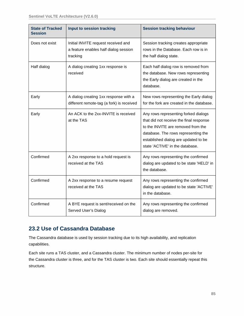
Sentinel VoLTE Architecture (V2.6.0)
State of TrackedSession
Input to session tracking Session tracking behaviour
Does not exist Initial INVITE request received and
a feature enables half dialog session
tracking
Session tracking creates appropriate
rows in the Database. Each row is in
the half dialog state.
Half dialog A dialog creating 1xx response is
received
Each half dialog row is removed from
the database. New rows representing
the Early dialog are created in the
database.
Early A dialog creating 1xx response with a
different remote-tag (a fork) is received
New rows representing the Early dialog
for the fork are created in the database.
Early An ACK to the 2xx-INVITE is received
at the TAS
Any rows representing forked dialogs
that did not receive the final response
to the INVITE are removed from the
database. The rows representing the
established dialog are updated to be
state 'ACTIVE' in the database.
Confirmed A 2xx response to a hold request is
received at the TAS
Any rows representing the confirmed
dialog are updated to be state 'HELD' in
the database.
Confirmed A 2xx response to a resume request
received at the TAS
Any rows representing the confirmed
dialog are updated to be state 'ACTIVE'
in the database.
Confirmed A BYE request is sent/received on the
Served User’s Dialog
Any rows representing the confirmed
dialog are removed.
23.2 Use of Cassandra Database
The Cassandra database is used by session tracking due to its high availability, and replication
capabilities.
Each site runs a TAS cluster, and a Cassandra cluster. The minimum number of nodes per-site for
the Cassandra cluster is three, and for the TAS cluster is two. Each site should essentially repeat this
structure.
85
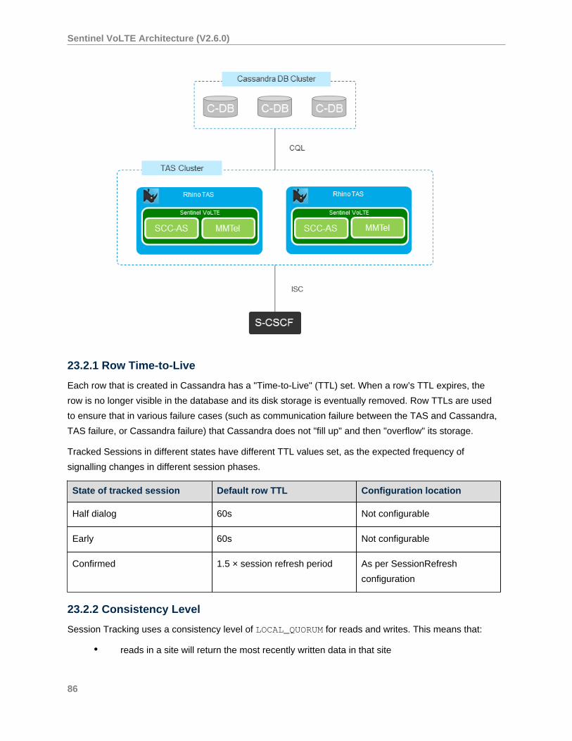
Sentinel VoLTE Architecture (V2.6.0)
23.2.1 Row Time-to-Live
Each row that is created in Cassandra has a "Time-to-Live" (TTL) set. When a row’s TTL expires, the
row is no longer visible in the database and its disk storage is eventually removed. Row TTLs are used
to ensure that in various failure cases (such as communication failure between the TAS and Cassandra,
TAS failure, or Cassandra failure) that Cassandra does not "fill up" and then "overflow" its storage.
Tracked Sessions in different states have different TTL values set, as the expected frequency of
signalling changes in different session phases.
State of tracked session Default row TTL Configuration location
Half dialog 60s Not configurable
Early 60s Not configurable
Confirmed 1.5 × session refresh period As per SessionRefresh
configuration
23.2.2 Consistency Level
Session Tracking uses a consistency level of LOCAL_QUORUM for reads and writes. This means that:
• reads in a site will return the most recently written data in that site
86
Sentinel VoLTE Architecture (V2.6.0)
• to survive a single database failure, a minimum of three Cassandra database instances must
be configured per site
• database replication occurs synchronously within a site, and asynchronously between sites
• there will be a replication lag between sites due to inter-site communication latency.
23.2.3 Cassandra Schema
Session Tracking uses two tables to represent a Tracked Session . Each tracked session has one
or more rows present in the Cassandra Database. These are the trackeddialog table, and the
trackeddialogkeys table. The trackeddialog table has the fully-formed Dialog ID of the SIP dialog
as the primary key. The trackeddialogkeys table uses a Cassandra capability of a two part primary
key, essentially to provide "Additional keys" to look up data, as Cassandra does not provide an optimal
secondary key mechanism.
The primary key for the trackeddialogkeys table is a composite of the trackingkey (text), and the
fully-formed dialog ID.
The schema itself can be viewed in External Session Tracking Cassandra Schema
23.3 Minimising the impact of Database issues on Session processing
As the SCC-AS is involved in potentially all originating IMS INVITE sessions, and all terminating IMS
sessions, care is taken to reduce the impact of a database failure.
When tracking sessions the TAS uses the following strategies:
• Write-only statements for session tracking - session tracking only writes to the Cassandra
Database. All data necessary to be written is held in local session state. Application features
(such as SCC features) then add a read path as necessary. This enables global access to
session tracking state.
• Batch statements - any query that affects multiple rows is executed as a batch statement.
• Asynchronous queries - threads used for processing signalling messages are not blocked
waiting for a response from the database.
• Signaling visibility after database transaction - signalling is only written "on the wire" after the
database transaction has completed, or a guard timer has fired.
• Per-query guard timeout - the TAS arms an internal timer for each Cassandra query, and if
it fires before there is a response from Cassandra, signalling continues and the session is
marked as "not tracked" so that further tracking of that session is disabled.
The effect of the guard timeout firing is that the user’s session setup can be successful, albeit with a small
delay (the guard timer value). However if PS to CS SR-VCC is attempted, the access transfer may fail as
when reading from the Cassandra Database the SCC-AS is likely to obtain either:
87
Sentinel VoLTE Architecture (V2.6.0)
• no tracked session information - as rows may not have been created, or may have been
removed due to TTL, or
• out-of-date information - as there may have been successful queries prior to a query hitting
its guard timer
23.4 Session Tracking Features
Session Tracking is implemented by the External Session Tracking Features in the Sentinel VoLTE
Administration Guide.
88
Sentinel VoLTE Architecture (V2.6.0)
24 Shared ATU-STI
The Access Transfer Update - Session Transfer Identifier (ATU-STI) is a SIP URI assigned to a device
during registration, if 3GPP Rel10 (or later) enhanced Single Radio VCC (eSRVCC) is to be applied to
that device’s sessions. In releases prior to Sentinel VoLTE 2.6.0 each TAS cluster member was required
to have its own ATU-STI. As of release 2.6.0, TAS cluster members may share an ATU-STI, and indeed
multiple TAS clusters may also share an ATU-STI.
The ATU-STI is used by the ATCF in order to route an INVITE due to ATU-STI to the SCC-AS as part of
PS to CS SRVCC Access Transfer with ATCF enhancements. In the rest of this page, an INVITE due to
ATU-STI, or an INVITE due to STN-SR that arrives at the SCC-AS is referred to as a "Handover INVITE".
Every TAS cluster member must be assigned a unique SCC-AS-URI that is routable between the TAS
cluster. If multiple TAS clusters share an ATU-STI, then all TAS cluster members must be assigned a
globally unique SCC-AS-URI, that must be routable from any node in any cluster, to any other node.
The ATU-STI must be routable between the ATCF (in the visited and home networks) and the SCC-AS (in
the home network).
The capability of having a Shared ATU-STI is possible through the SCC-AS using the Session Tracking
on page 84 infrastructure.
24.1 Co-ordinating Access Transfer
A device may participate in several sessions at once. For example, it may have an ACTIVE session,
and several HELD sessions; or it may have an ACTIVE session and an ALERTING session; and so-on.
The SCC-AS signalling anchor instances for each of this device’s sessions may reside on different TAS
cluster members, and possibly different TAS clusters. When multiple TAS nodes (regardless of which
cluster) share an ATU-STI, a Handover INVITE may arrive at any of the nodes. Yet different nodes may
be serving that device’s sessions. Therefore there is a need to co-ordinate Access Transfer between the
nodes sharing the ATU-STI.
The following diagram shows a four node TAS cluster, where all nodes share a single ATU-STI. There are
four sessions in progress. Three sessions share the same Correlation-MSISDN (C-MSISDN) (12345) and
so are for the same device. Each session’s signalling anchor is located on different TAS cluster members.
The Session Tracking Database (Cassandra) is storing the location and other meta-data (e.g. the SCC-
AS-URI, and state fields) related to each of these sessions.
89
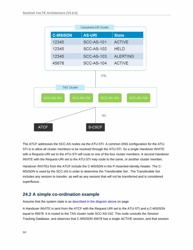
Sentinel VoLTE Architecture (V2.6.0)
The ATCF addresses the SCC-AS nodes via the ATU-STI. A common DNS configuration for the ATU-
STI is to allow all cluster members to be resolved through the ATU-STI. So a single Handover INVITE
with a Request-URI set to the ATU-STI will route to one of the four cluster members. A second Handover
INVITE with the Request-URI set to the ATU-STI may route to the same, or another cluster member.
Handover INVITEs from the ATCF include the C-MSISDN in the P-Asserted-Identity header. The C-
MSISDN is used by the SCC-AS in order to determine the Transferable Set . The Transferable Set
includes any session to transfer, as well as any session that will not be transferred and is considered
superfluous .
24.2 A simple co-ordination example
Assume that the system state is as described in the diagram above on page .
A Handover INVITE is sent from the ATCF with the Request URI set to the ATU-STI and a C-MSISDN
equal to 45678. It is routed to the TAS cluster node SCC-AS-102. This node consults the Session
Tracking Database, and observes that C-MSISDN 45678 has a single ACTIVE session, and that session
90
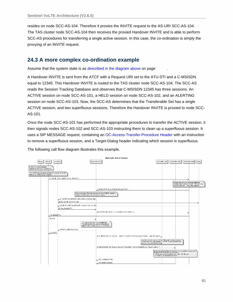
Sentinel VoLTE Architecture (V2.6.0)
resides on node SCC-AS-104. Therefore it proxies the INVITE request to the AS-URI SCC-AS-104.
The TAS cluster node SCC-AS-104 then receives the proxied Handover INVITE and is able to perform
SCC-AS procedures for transferring a single active session. In this case, the co-ordination is simply the
proxying of an INVITE request.
24.3 A more complex co-ordination example
Assume that the system state is as described in the diagram above on page .
A Handover INVITE is sent from the ATCF with a Request URI set to the ATU-STI and a C-MSISDN
equal to 12345. This Handover INVITE is routed to the TAS cluster node SCC-AS-104. The SCC-AS
reads the Session Tracking Database and observes that C-MSISDN 12345 has three sessions. An
ACTIVE session on node SCC-AS-101, a HELD session on node SCC-AS-102, and an ALERTING
session on node SCC-AS-103. Now, the SCC-AS determines that the Transferable Set has a single
ACTIVE session, and two superfluous sessions. Therefore the Handover INVITE is proxied to node SCC-
AS-101.
Once the node SCC-AS-101 has performed the appropriate procedures to transfer the ACTIVE session, it
then signals nodes SCC-AS-102 and SCC-AS-103 instructing them to clean up a superfluous session. It
uses a SIP MESSAGE request, containing an OC-Access-Transfer-Procedure Header with an instruction
to remove a superfluous session, and a Target-Dialog header indicating which session is superfluous.
The following call flow diagram illustrates this example.
91


![Architecture VoLTE/IMS · 2014. 2. 21. · Architecture VoLTE/IMS [SE17] Participants Architectes réseaux, Ingénierie réseaux, R&D. PA1 PA3 AC8 AC11 AC12 AC13 AC14 CO8 CO9 SE1](https://img.dokumen.tips/doc/110x75/6128b13f0ea3ba2f6a0fd605/architecture-volte-2014-2-21-architecture-volteims-se17-participants-architectes.jpg)