Embed Size (px)
Citation preview
Department of Electrical and Computer Engineering Howard University
Senior Design Project:
Blind Assist: Project Report
Oluwaseyitan Joshua Durodola Nathaniel Sims Chris Uruquhart
Date: April 25th 2012
Durodola, Sims, UruquhartBlind Assist: Final Report
2012
2
SUBMISSION AND APPROVAL This project report is submitted for partial fulfillment of the Senior Design course describing the design and implementation of our project. We certify that this is an accurate Final Report and we are in agreement that this report is an accurate representation of the project. __________________________________________________________________ Name Signature Date __________________________________________________________________ Name Signature Date __________________________________________________________________ Name Signature Date I certify that this report is an accurate representation of the Project and I approve it __________________________________________________________________ Course Instructor Signature Date
Durodola, Sims, UruquhartBlind Assist: Final Report
2012
3
Table of Contents 1. Executive Summary .................................................................................................................... 5
1.1 Objective of the project .................................................................................................... 5 1.2 Background of the project ..................................................................................................... 5
2. Problem ....................................................................................................................................... 5 2.1 Problem formulation ............................................................................................................. 5 2.2 Problem definition ................................................................................................................ 6 2.3 Design Requirements ............................................................................................................ 6
3. Current Status of Art ................................................................................................................... 8 3.1 Available devices .................................................................................................................. 8 3.2 Drawback on available devices ............................................................................................. 9
4. Solution Approach ...................................................................................................................... 9 4.1 Top Design Selection .......................................................................................................... 12
4.1.1 Distance Calculation sensors (Infra-red or Ultrasonic Sensors) .................................. 12 4.1.2 Obstacle Alert output (Wireless vibrating wristbands or audible tone/pulses) ............ 12 4.1.3 Method of inputting addresses (Voice synthesis or Braille Keyboard) ....................... 13
4.2 Device integration and description ..................................................................................... 14 5. Project Execution Overview: .................................................................................................... 15
5.1 Project execution plan ......................................................................................................... 15 5.2 Project Timeline .................................................................................................................. 16 5.3 Challenges, Risks and Control during execution ................................................................ 16
5.3.1 Wireless vibrating wristband ....................................................................................... 17 5.3.2 Overhead software (‘BOSS’) and function management ............................................ 18 5.3.3 Limited accuracy of GPS ............................................................................................. 19
5.4 Costs and resources ............................................................................................................. 19 6. Performance Evaluation: ........................................................................................................... 20 7. Recommendations ..................................................................................................................... 23 8. Nomenclature Glossary ............................................................................................................. 29 9. Conclusion ................................................................................................................................ 29 10. Acknowledgements ................................................................................................................. 30 11. References ............................................................................................................................... 30 12. Appendix ................................................................................................................................. 31
12.1 Technical Documentation: ................................................................................................ 31 12.1.1 Obstacle Alert ............................................................................................................ 32
Durodola, Sims, UruquhartBlind Assist: Final Report
2012
4
12.1.2 Directions to Location Software ................................................................................ 36 12.1.3 “BOSS” (Overhead software) .................................................................................... 39
Durodola, Sims, UruquhartBlind Assist: Final Report
2012
5
1. Executive Summary
This report contains details of the design and completion of the Blind Assist project.
1.1 Objective of the project
The aim of this project is to propose a portable device, designed for visually impaired
individuals to assist them with getting around. Unlike most commercially available assistive
devices, this device should provide directions to locations and alert the user of obstacles in their
path.
1.2 Background of the project
The project was born by the team’s intent to participate in the 2011 Cornell Cup
competition. The competition required each team to design a system that innovatively used
embedded technology. We considered the number of visually impaired individuals in the world
and decided it was a worthwhile project to create an assistive device for visually impaired
individuals.
2. Problem
2.1 Problem formulation
There are over 284 million people who are visually impaired and there are over 39
million people who are totally blind [1]. The lack of visual capabilities has limited these
individuals from completely perceiving their immediate surroundings which has potential safety
concerns and also lowers their quality of life since they must rely on some sort of aid to get
around. Currently, in order for visually impaired individuals to get around, they rely on walking
Durodola, Sims, UruquhartBlind Assist: Final Report
2012
6
canes, guide dogs, and/or personal human aids for assistance. While these walking canes and
guide dogs may allow the individual to get around independently, they each have a common
drawback. These aids lack the intelligence to provide directions to unvisited locations and cannot
completely warn individuals of obstruent objects in their vicinity. A human aid provides this
intelligence but makes the visually impaired individual very dependent on the human aid.
A good solution will be a device that is portable and is able to provide directions to new
locations and alert the user of obstacles in their path when the user is walking. For the purpose of
this project, we streamlined the problem defined above to assisting blind individuals with getting
around outdoors. We believe a project like this will create the case for further investment in
creating smarter electronic devices to assist visually impaired individuals with getting around.
By smarter we mean that the device is able to provide directions to unvisited locations, while
ensuring safe navigation. Additionally, the device is not intended to replace the use of walking
canes or guide dogs.
2.2 Problem definition
Design a portable device for visually impaired individuals that will provide direction to new
locations and alert the user of obstacles in their path during outdoor navigation.
2.3 Design Requirements
Design Requirements – Blind Assist
The constraints imposed on this project require that our proposed design must meet the
Following requirements:
1. Overall Function:
a. Should alert user of impeding obstacles while walking.
b. Should direct users using GPS to desired locations.
Durodola, Sims, UruquhartBlind Assist: Final Report
2012
7
2. Performance:
a. Should take no longer than 3 minutes to boot up from a full shutdown to fully
operational mode
b. Should be able to identify an obstacle with an area larger than 18 in2
c. Should alert user when obstacle is at a distance of at least 3 feet
d. Should operate when user is walking a maximum of 3 feet per second
e. Should not issue warning if the turn signal is activated.
f. Should direct users within 50 feet of their destination.
g. Should find GPS signal within 1 minute of initialization.
3. Aesthetics:
a. Should weigh less than 5 lbs
b. Main system should fit within a 12 x 8 x 4 in dimension
3. Compliance:
a. Blind Assist must meet all of the following regulations
The FCC rules and regulations part 24 (As regards GSM modem for internet access)
ADA regulations (Entire system)
FCC Hearing Aid Compatibility (HAC) Regulations for Wireless devices
(Bluetooth Earpiece)
FCC regulations on Specific Absorption Rate (SAR) of electronic devices (GSM
Modem, Bluetooth Earpiece, Electromagnetic Radiation from the Intel Atom
Board)
4. User-System Interface:
a. System should include vibration modules rated at 1.5V/10mA .
Durodola, Sims, UruquhartBlind Assist: Final Report
2012
8
b. System should issue an audible and/or haptic warning when the obstacle is within 3
feet.
c. System should issue warnings to denote status of system (idle/seized/loading).
5. Power:
a. Should operate for 5 hours of continuous use
b. Should be able to fully charge from nil within 3 hours
c. Battery should last 48hours on stand by
3. Current Status of Art
Assisting devices for the blind have been around for a while, but it wasn’t until recently
with the advancement of semiconductor technology that these devices really started to take off.
Though there are many devices that help the visually impaired, these devices often only serve
one purpose.
3.1 Available devices
Trekker- Talking GPS - Trekker introduces a GPS system for the visually impaired. The
Trekker Breeze is a handheld talking GPS that can be controlled with one hand. It verbally
announces the names of streets, intersections, and landmarks as you walk. This device is
supposed to allow you greater freedom and the independence of having to stop and ask a
passerby to know where you are. The Breeze also quickly becomes familiar with new routes that
Durodola, Sims, UruquhartBlind Assist: Final Report
2012
9
you travel. They also have a feature that allows you to easily retrace your steps if you get lost,
with the addition of a simple push button.
Kapten Plus Voice Activated GPS- the Kapten Plus is a GPS unit for the visually
impaired. It features high-performance GPS along with free navigation modes that provide real
time voice description of what’s around you. It has automatic speech recognition that allows you
to control the device just through your voice. It also features a multitransport navigation mode
that differentiates between pedestrian, bike, motorbike, and car modes. The Kapten also features
a voice-controlled FM radio and MP3 player.
WuFu - The WuFu is a proximity measuring device. This device makes use of ultrasonic
distance measurements. It uses ultrasonic sensors that sense obstacles in front of the user. It then
sends a signal to motors attached to the wrists of the wearer that vibrate, alerting the user of an
obstacle.
HandGuide –Talking Solutions gives us a system Uses high-tech, infrared sensors to
detect objects within four feet. It offers a choice of two modes to detect objects and provide a
sense of their distance. Audio modes uses pitch variation and vibration mode uses vibration
variations.
3.2 Drawback on available devices
All the devices mentioned above work great at one task. A few devices provide GPS
directions and the others sense impeding obstacles but none of them both provide GPS directions
and alert the user of obstacles in their path.
4. Solution Approach
Durodola, Sims, UruquhartBlind Assist: Final Report
2012
10
Our proposed solution approach is to design a mobile embedded device that will help
visually impaired individuals with their independent mobility. The device will direct them to and
from specified locations (mall, grocery store etc.), and alert the user of any potential obstructions
in their path. A technological approach would be useful because access to internet and GPS will
help increase their independence by helping them get to locations they don’t normally travel to.
The scope of the project is to provide user directions to locations when they are outdoors
and also alert the user of obstacles in their path while they are trying to get to those locations.
The blind assist project will be the integration of sensors (ultrasonic sensors, Bluetooth, etc),
GSM internet, GPS, and the ATOM processor. After we integrate all the hardware we will create
a software function that translates information gathered by the hardware into directions and
obstacle alerts. The device will not analyze and identify objects within the field of view of the
user. The device will not be designed to replace any human senses. For example the device will
not use a camera to describe a scene to the user as if to replace sight. We will also limit the
scope of our device to just being used only outdoors. We do not intend to eliminate use of
walking canes, guide dogs, or personal aides.
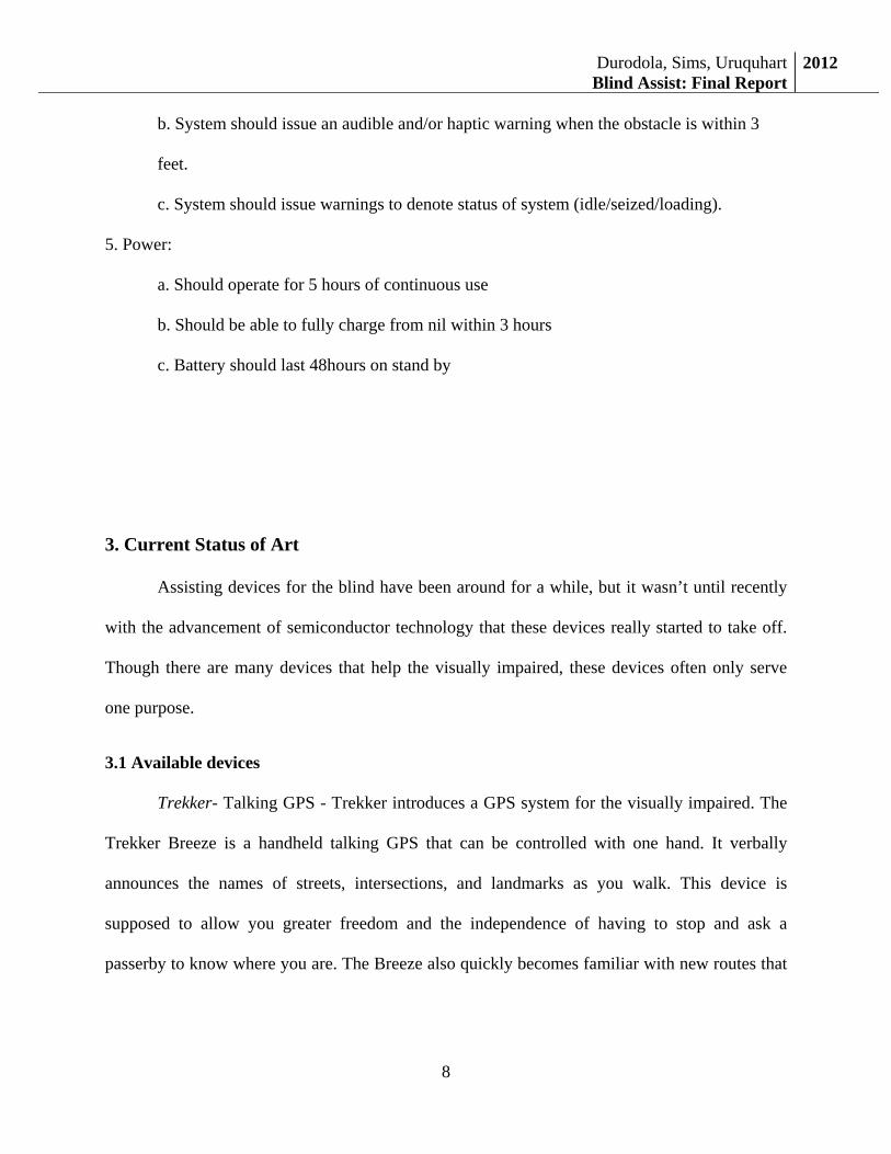
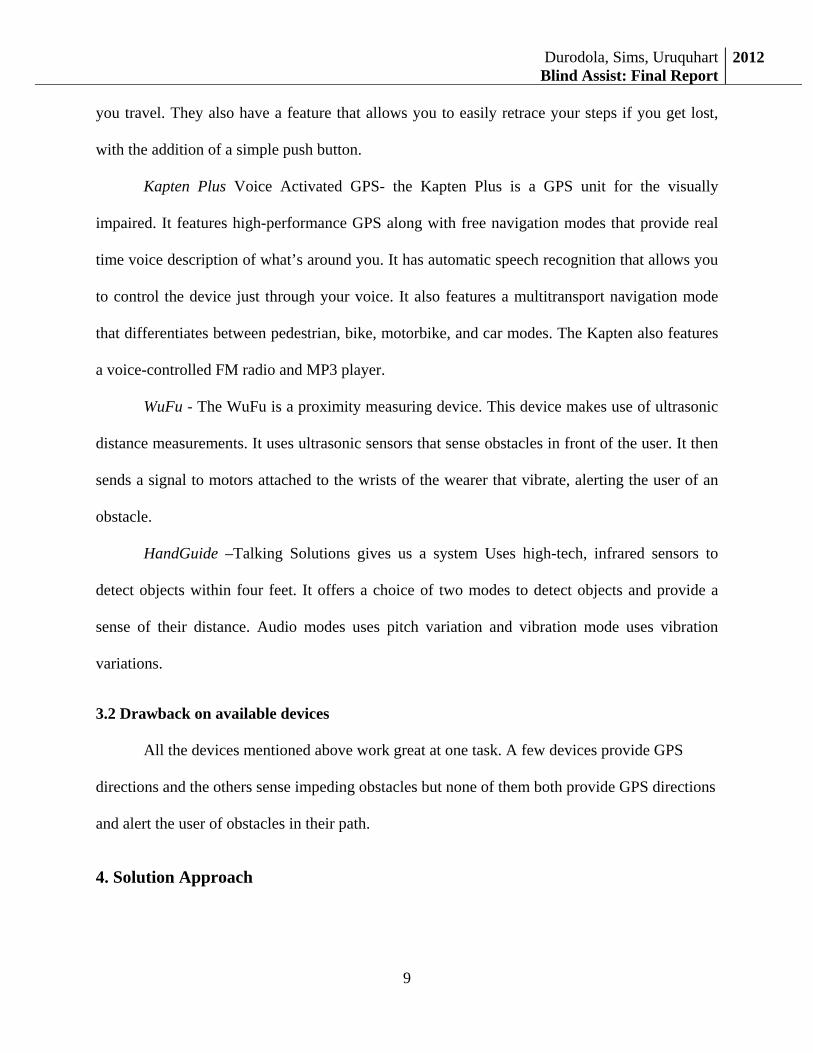
For our solution implementation the atom processor will be the focal point of our design.
It will constantly receive three core pieces of information from various sensors. The three pieces
of information are distance of an object from the user, user request for directions, and request for
date and time. The atom processor will use various functions illustrated in Figure 2 in order to
generate four outputs. The four outputs are; verbal turn by turn directions, confirmation of voice
request, obstacle alert, and verbal date and time response. Internet and GPS are two major
enabling resources whose resources are called upon by various function, this is also illustrated in
Figure 2.
Durodola, Sims, UruquhartBlind Assist: Final Report
2012
11
Figure 1: System Diagram
Voice
Requ
est
Processin
g
Info to
Voice
Processin
g
Figure 2: Atom software functions
Although the system diagrams above described input from the user through Bluetooth
transceiver, during the design process and when we analyzed possible components for the
Durodola, Sims, UruquhartBlind Assist: Final Report
2012
12
functions we needed with our device we made a couple of changes. One of the major changes
was we changed the input format for when the user wants to put in an address. Rather than
speaking and doing voice synthesis, we opted for a keyboard with braille stickers. Below are the
alternative components and our justification for our choice for our final system design.
4.1 Top Design Selection
For our top design selection, we considered all the functions we needed our device to
have, listed the possible components that could be used and weighed each of the options through
decision matrices.
4.1.1DistanceCalculationsensors(Infra‐redorUltrasonicSensors)
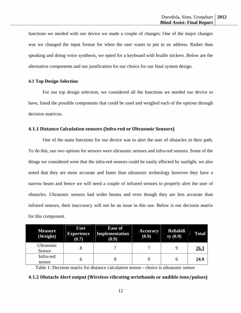
One of the main functions for our device was to alert the user of obstacles in their path.
To do this, our two options for sensors were ultrasonic sensors and infra-red sensors. Some of the
things we considered were that the infra-red sensors could be easily affected by sunlight, we also
noted that they are more accurate and faster than ultrasonic technology however they have a
narrow beam and hence we will need a couple of infrared sensors to properly alert the user of
obstacles. Ultrasonic sensors had wider beams and even though they are less accurate than
infrared sensors, their inaccuracy will not be an issue in this use. Below is our decision matrix
for this component.
Measure (Weight)
User Experience
(0.7)
Ease of Implementation
(0.9)
Accuracy (0.9)
Reliability (0.9) Total
Ultrasonic Sensor 8 7 7 9 26.3
Infra-red sensor 6 8 9 6 24.9
Table 1: Decision matrix for distance calculation sensor - choice is ultrasonic sensor
4.1.2ObstacleAlertoutput(Wirelessvibratingwristbandsoraudibletone/pulses)
Durodola, Sims, UruquhartBlind Assist: Final Report
2012
13
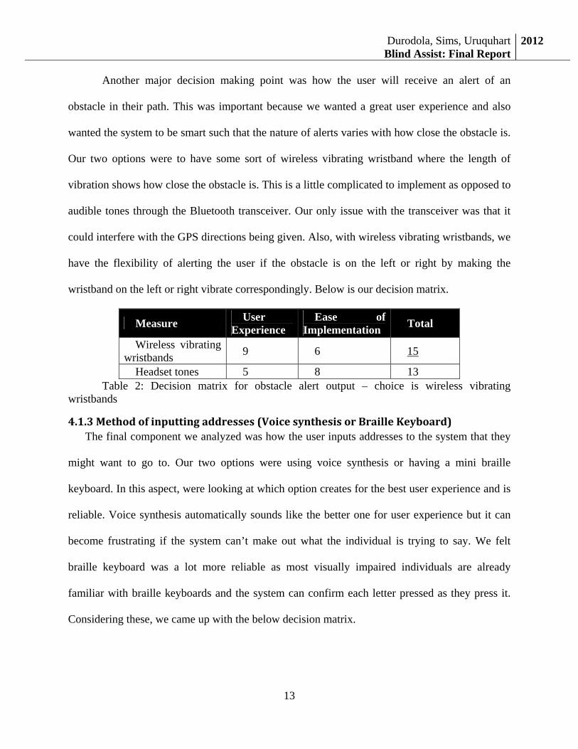
Another major decision making point was how the user will receive an alert of an
obstacle in their path. This was important because we wanted a great user experience and also
wanted the system to be smart such that the nature of alerts varies with how close the obstacle is.
Our two options were to have some sort of wireless vibrating wristband where the length of
vibration shows how close the obstacle is. This is a little complicated to implement as opposed to
audible tones through the Bluetooth transceiver. Our only issue with the transceiver was that it
could interfere with the GPS directions being given. Also, with wireless vibrating wristbands, we
have the flexibility of alerting the user if the obstacle is on the left or right by making the
wristband on the left or right vibrate correspondingly. Below is our decision matrix.
Measure User Experience
Ease of Implementation Total
Wireless vibrating wristbands 9 6 15
Headset tones 5 8 13 Table 2: Decision matrix for obstacle alert output – choice is wireless vibrating
wristbands
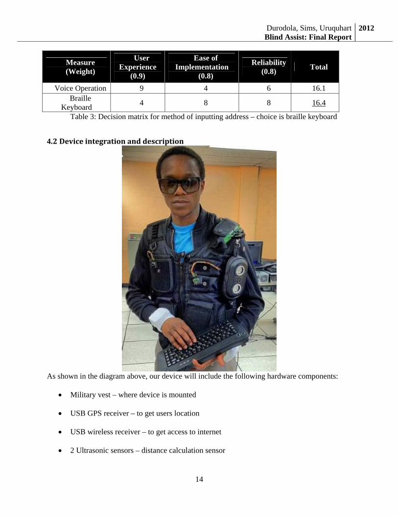
4.1.3Methodofinputtingaddresses(VoicesynthesisorBrailleKeyboard)The final component we analyzed was how the user inputs addresses to the system that they
might want to go to. Our two options were using voice synthesis or having a mini braille
keyboard. In this aspect, were looking at which option creates for the best user experience and is
reliable. Voice synthesis automatically sounds like the better one for user experience but it can
become frustrating if the system can’t make out what the individual is trying to say. We felt
braille keyboard was a lot more reliable as most visually impaired individuals are already
familiar with braille keyboards and the system can confirm each letter pressed as they press it.
Considering these, we came up with the below decision matrix.
Durodola, Sims, UruquhartBlind Assist: Final Report
2012
14
Measure (Weight)
User Experience
(0.9)
Ease of Implementation
(0.8)
Reliability (0.8) Total
Voice Operation 9 4 6 16.1 Braille
Keyboard 4 8 8 16.4
Table 3: Decision matrix for method of inputting address – choice is braille keyboard
4.2 Deviceintegrationanddescription
As shown in the diagram above, our device will include the following hardware components:
• Military vest – where device is mounted
• USB GPS receiver – to get users location
• USB wireless receiver – to get access to internet
• 2 Ultrasonic sensors – distance calculation sensor
Durodola, Sims, UruquhartBlind Assist: Final Report
2012
15
• Mini wireless keyboard with braille stickers – for inputting desired address
• Wire keypad – control keypad that allows user turn on/off system, request system
status(date, time, internet connection), turn on/off obstacle alert and turn on/off GPS
directions
• Arduino microcontroller – used to connect ultrasonic sensors to atom board
• 3 Sun Trust microprocessors – one acts as the base station while the other two are
connected wirelessly and are attached to a wristband with vibrators mounted on them.
These parts work together to create the Blind Assist. At the Cornell Cup Expo we plan to
blindfold a user and have them ask for directions to one of five predetermined locations within
ten minute walking distance of the expo center. At least one team member will walk with the
user to ensure their safety.
5.ProjectExecutionOverview:The execution of the project was our real design experience. Included in our project proposal
was a timeline for our project including major milestones and when we intend to complete these
milestones. The timeline and milestones were created based off our project execution plan.
5.1Projectexecutionplan
As planned by our team, our steps in the execution plan were:
• Learn about atom processor
• Divide system into functional blocks
o Obstacle Alert
o Directions to location
• Develop the functional blocks above
• Test components/functions against design requirements
Durodola, Sims, UruquhartBlind Assist: Final Report
2012
16
• Plan and implement system integration
• Test system against design requirements
• Modify the system as necessary
This project execution plan proved to be very useful as we followed it and were able to complete
our project and meet most of the design requirements
5.2ProjectTimeline
Below is an abridged version of the timeline we set for our project.
Time Period Tasks Deliverables
November 2011 Learn atom processor Know strengths, limitations, compatibility
December 2011 and January 2012
Commence in formulation of functional blocks
Obstacle Alert. Voice commands, Directions to Locations
February 2012 System Integration Plan and assemble for synchronous operation after component test
March 2012 Test prototype Test subsystems and device meet requirements
April 2012 Modify device Make changes for satisfactory performance
April to Mid May 2012 Develop final report and presentation for Intel Cup
Present at competition
Unfortunately, we were unable to follow our timeline as we fell almost a month behind after the
Christmas break, however we doubled our effort to ensure we completed our project.
5.3Challenges,RisksandControlduringexecution
During the execution of our project, we encountered a couple of issues that had to deal with.
Additionally, we continually highlighted risks to our project completion and some control steps
Durodola, Sims, UruquhartBlind Assist: Final Report
2012
17
against those risks. For areas that we could not implement the solutions, we included possible
solutions in future work. We will begin describing the challenges, risks and controls.
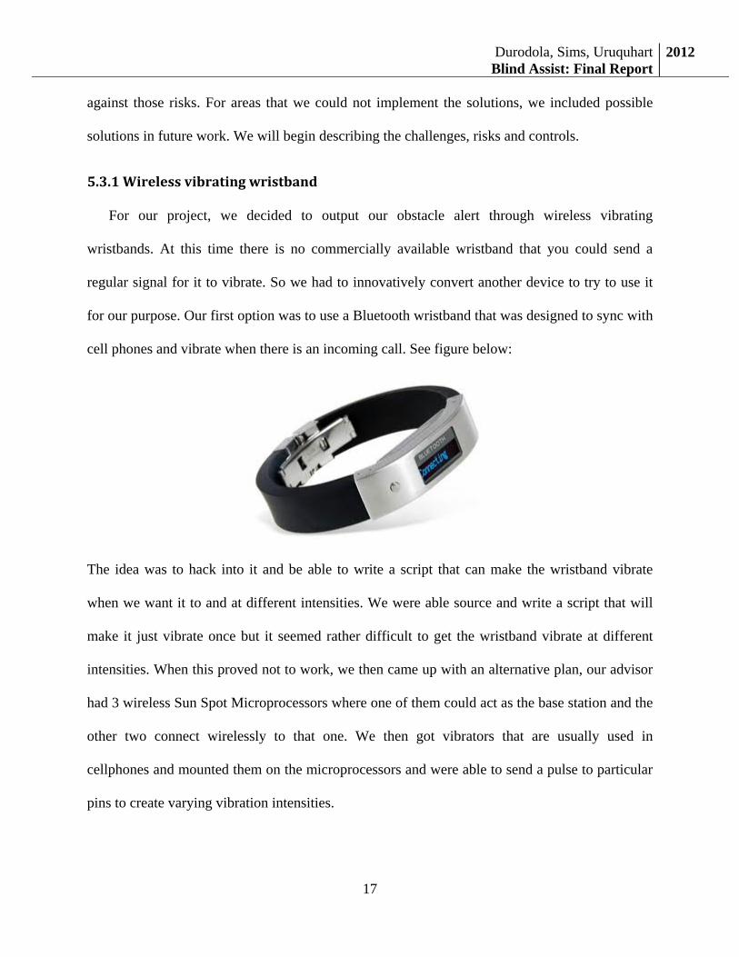
5.3.1Wirelessvibratingwristband
For our project, we decided to output our obstacle alert through wireless vibrating
wristbands. At this time there is no commercially available wristband that you could send a
regular signal for it to vibrate. So we had to innovatively convert another device to try to use it
for our purpose. Our first option was to use a Bluetooth wristband that was designed to sync with
cell phones and vibrate when there is an incoming call. See figure below:
The idea was to hack into it and be able to write a script that can make the wristband vibrate
when we want it to and at different intensities. We were able source and write a script that will
make it just vibrate once but it seemed rather difficult to get the wristband vibrate at different
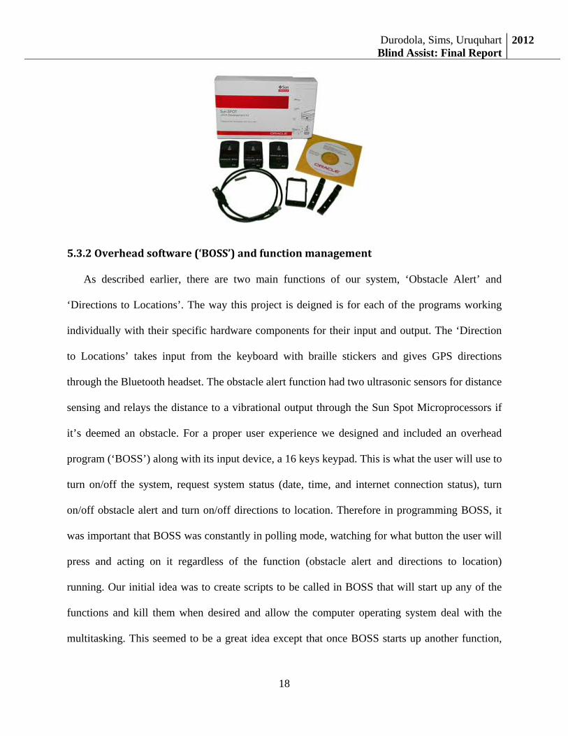
intensities. When this proved not to work, we then came up with an alternative plan, our advisor
had 3 wireless Sun Spot Microprocessors where one of them could act as the base station and the
other two connect wirelessly to that one. We then got vibrators that are usually used in
cellphones and mounted them on the microprocessors and were able to send a pulse to particular
pins to create varying vibration intensities.
Durodola, Sims, UruquhartBlind Assist: Final Report
2012
18
5.3.2Overheadsoftware(‘BOSS’)andfunctionmanagement
As described earlier, there are two main functions of our system, ‘Obstacle Alert’ and
‘Directions to Locations’. The way this project is deigned is for each of the programs working
individually with their specific hardware components for their input and output. The ‘Direction
to Locations’ takes input from the keyboard with braille stickers and gives GPS directions
through the Bluetooth headset. The obstacle alert function had two ultrasonic sensors for distance
sensing and relays the distance to a vibrational output through the Sun Spot Microprocessors if
it’s deemed an obstacle. For a proper user experience we designed and included an overhead
program (‘BOSS’) along with its input device, a 16 keys keypad. This is what the user will use to
turn on/off the system, request system status (date, time, and internet connection status), turn
on/off obstacle alert and turn on/off directions to location. Therefore in programming BOSS, it
was important that BOSS was constantly in polling mode, watching for what button the user will
press and acting on it regardless of the function (obstacle alert and directions to location)
running. Our initial idea was to create scripts to be called in BOSS that will start up any of the
functions and kill them when desired and allow the computer operating system deal with the
multitasking. This seemed to be a great idea except that once BOSS starts up another function,
Durodola, Sims, UruquhartBlind Assist: Final Report
2012
19
the active program does not return to BOSS so we are out of our polling mode. Therefore, we
had to implement multi-threading to allow BOSS hold the other two functions and create new
threads and keep BOSS in it’s a polling mode.
5.3.3LimitedaccuracyofGPS
Another major challenge we had to deal with is the current accuracy of GPS systems. Right
now, GPS systems are accurate to 33ft 95% of the time. Although we considered this when
creating our design requirements, we believe there is more work to be done as bringing a visually
impaired individual with 40ft of their desired destination is not suitable. Additionally, we are
considering including a digital compass in our system. This will allow us to give more useful
directions to the visually impaired individual. More of this is covered in our future plans.
5.4Costsandresources
Below, we outline the components we used alongside their costs or if they were sourced.
Component Cost Source Maxbotix Ultrasonic Sensors $73.00 Purchased Bluetooth dongle $24.00 Purchased Bluetooth headset transceiver $40.00 Provided by Chris
Sun SPOT microprocessors $300.00Provided by advisor
Arduino microcontroller $40.00 Provided by Chris Wireless mini keyboard $22.83 Purchased Bluetooth Vibrating bracelets(not used) $64.00 Purchased Connection wires $12.48 Purchased Military vest $42.53 Purchased Battery pack $80.00 Purchased Battery regulator $24.00 Purchased USB GPS receiver $48.00 Purchased 16 key Keypad $30.00 Purchased USB Wireless internet receiver $40.00 Sourced I/O Explorer (not used) $100.00 Purchased
Durodola, Sims, UruquhartBlind Assist: Final Report
2012
20
6.PerformanceEvaluation:
Our proposed solution was defined as mobile embedded device that will help visually
impaired individuals with their independent mobility. The device will direct them to and from
specified locations (mall, grocery store etc.), and alert the user of any potential obstructions in
their path. Looking back to this general definition of our proposed solution there where two key
tasks. First to direct them to and from a specific location and the second was to alert them of
possible obstructions. Looking at these two tasks from a high level our device is able to do both
core tasks.
The first task was direct the user to and from a location. Due to the complexities of voice
capture we decided to use hardware inputs to receive instructions from the user. We have two
hardware input methods; a small keypad and a small keyboard. The keypad is used to activate
and deactivate key functions like navigation, and obstacle alert. The keyboard is only used with
navigation and is how the user types where they want to go. Also the navigation system does not
require actual addresses but can use just a name and it will pull up nearby addresses (Ex:
Directions to Howard University).
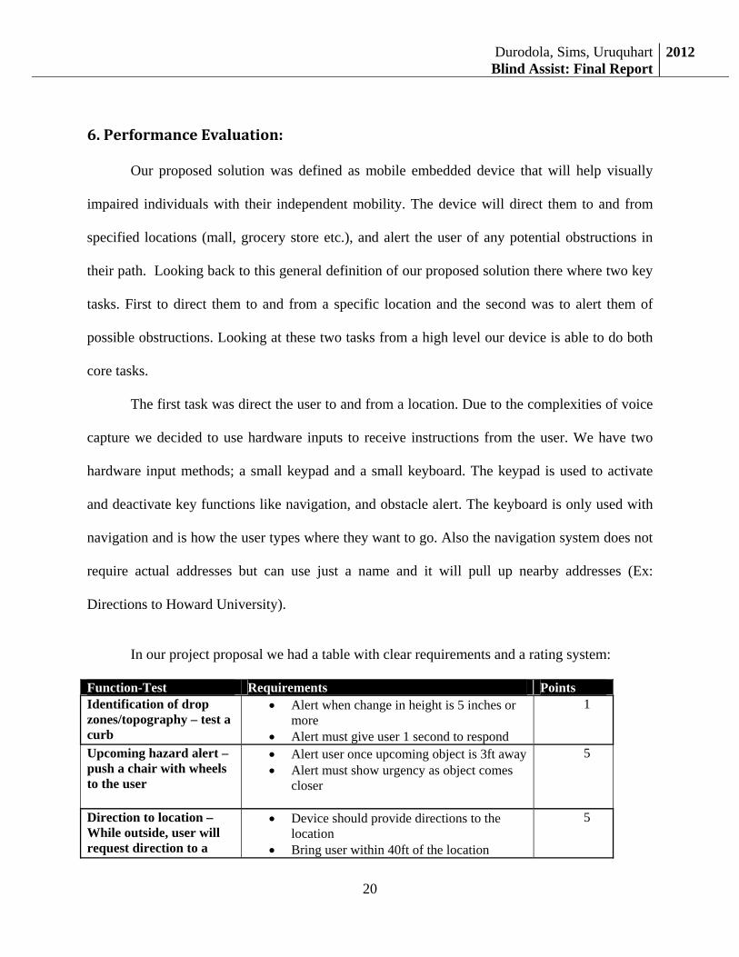
In our project proposal we had a table with clear requirements and a rating system:
Function-Test Requirements Points Identification of drop zones/topography – test a curb
• Alert when change in height is 5 inches or more
• Alert must give user 1 second to respond
1
Upcoming hazard alert – push a chair with wheels to the user
• Alert user once upcoming object is 3ft away • Alert must show urgency as object comes
closer
5
Direction to location – While outside, user will request direction to a
• Device should provide directions to the location
• Bring user within 40ft of the location
5
Durodola, Sims, UruquhartBlind Assist: Final Report
2012
21
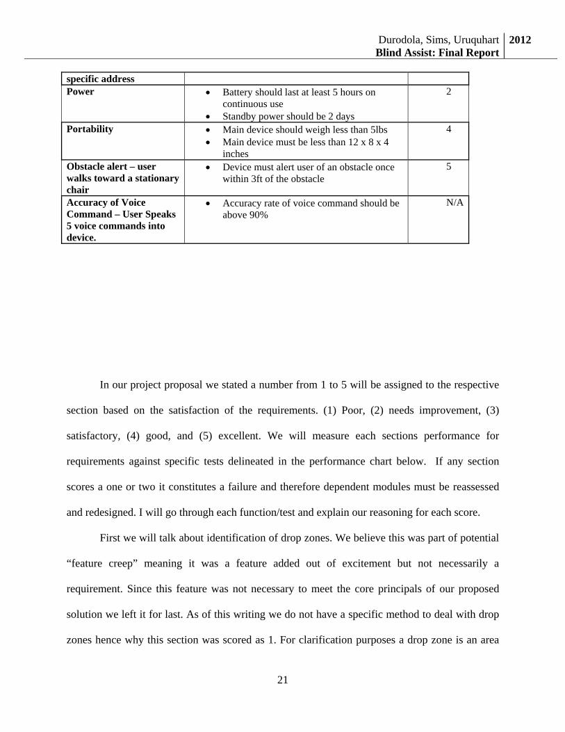
In our project proposal we stated a number from 1 to 5 will be assigned to the respective
section based on the satisfaction of the requirements. (1) Poor, (2) needs improvement, (3)
satisfactory, (4) good, and (5) excellent. We will measure each sections performance for
requirements against specific tests delineated in the performance chart below. If any section
scores a one or two it constitutes a failure and therefore dependent modules must be reassessed
and redesigned. I will go through each function/test and explain our reasoning for each score.
First we will talk about identification of drop zones. We believe this was part of potential
“feature creep” meaning it was a feature added out of excitement but not necessarily a
requirement. Since this feature was not necessary to meet the core principals of our proposed
solution we left it for last. As of this writing we do not have a specific method to deal with drop
zones hence why this section was scored as 1. For clarification purposes a drop zone is an area
specific address Power • Battery should last at least 5 hours on
continuous use • Standby power should be 2 days
2
Portability • Main device should weigh less than 5lbs • Main device must be less than 12 x 8 x 4
inches
4
Obstacle alert – user walks toward a stationary chair
• Device must alert user of an obstacle once within 3ft of the obstacle
5
Accuracy of Voice Command – User Speaks 5 voice commands into device.
• Accuracy rate of voice command should be above 90%
N/A
Durodola, Sims, UruquhartBlind Assist: Final Report
2012
22
where a person may have to abruptly “step down” (Ex: Curb, sharp slope). We thought a feature
like this could be advantageous for a blind person.
The next section was hazard alert. We scored this section as a 5 because we were able to
clearly meet this criterion. When a chair or person is moving towards the user and the objects
reach within 3 ft of the person our vibration modules alert the user. We have been able to log the
data of when the object crosses 3ft and creating the required vibrations.
The next section is directions to locations. This section was also scored with a 5 because
we are able to accurately receive an end location from the user and direct them to it. When the
user activates navigation they can use the brail keyboard to input a location, and using internet
and GPS the system will map the user to the end location and give them voice commands to get
them there.
Power received a score of two mainly because of the standby requirement. We have no
implementation of standby therefore the device is always on or off. When the device is on and
active we have only tested our device for two hours (The battery did not die though we just
stopped testing for the sake of time.)
Portability we scored ourselves a 5 because the device is extremely portable, we have
mounted all our components to a vest that a user can easily put on and take off.
Obstacle alert received a score of 5 and was tested at the same time we tested the hazard
section. As with the hazard section our device always vibrates when an obstacle enters within 3ft
of the user.
Accuracy of voice commands is no longer used as a metric because during the
implementation phase we decided against user voice input. Instead of using voice input we have
Durodola, Sims, UruquhartBlind Assist: Final Report
2012
23
hardware input choices a keypad and a keyboard. Using this method we have reduced all input
errors to user error rather than a system error.
7. Recommendations
In this section, we will be discussing the ways the blind assist device can be improved
through an addition of a compass, the usage of smart sensor system technology, the addition of a
lithium ion battery, and the deletion of the key pad for manual input.
The first step to improving this is to add a compass module to the Intel board. Using a ST
microelectronic MEMS digital compass module will allow this system to give more accurate
direction for the blind person. A digital compass module is a compass that combines high-
performance motion and magnetic sensing and enhances the mobile user experience. A digital
compass is actually a magnetometer. A magnetometer is a scientific instrument which measures
magnetic fields. In addition to determining the strength of a magnetic field, a magnetometer can
also determine its orientation and direction. These devices are used in the same way as a
compass. Incorporating this system would add a level of accuracy allowing the GPS portion of
the system to determine a person’s position allowing the individual to follow directives better.
Smart sensor system is the development of a new generation of smart sensors that can be
networked through the communication interface to have the capability of individual network
self-identification and communication allowing reprogramming of the smart sensor system as
necessary. A transformative advance in the field of sensor technology has been the development
of smart sensor system. The definition of a smart sensor is the combination of a sensing element
with processing capabilities provided by a microprocessor. Smart sensors are basic sensing
elements with embedded intelligence. The sensor signal is fed to the microprocessor, which
processes the data and provides and informative output to an external user. The fundamental idea
Durodola, Sims, UruquhartBlind Assist: Final Report
2012
24
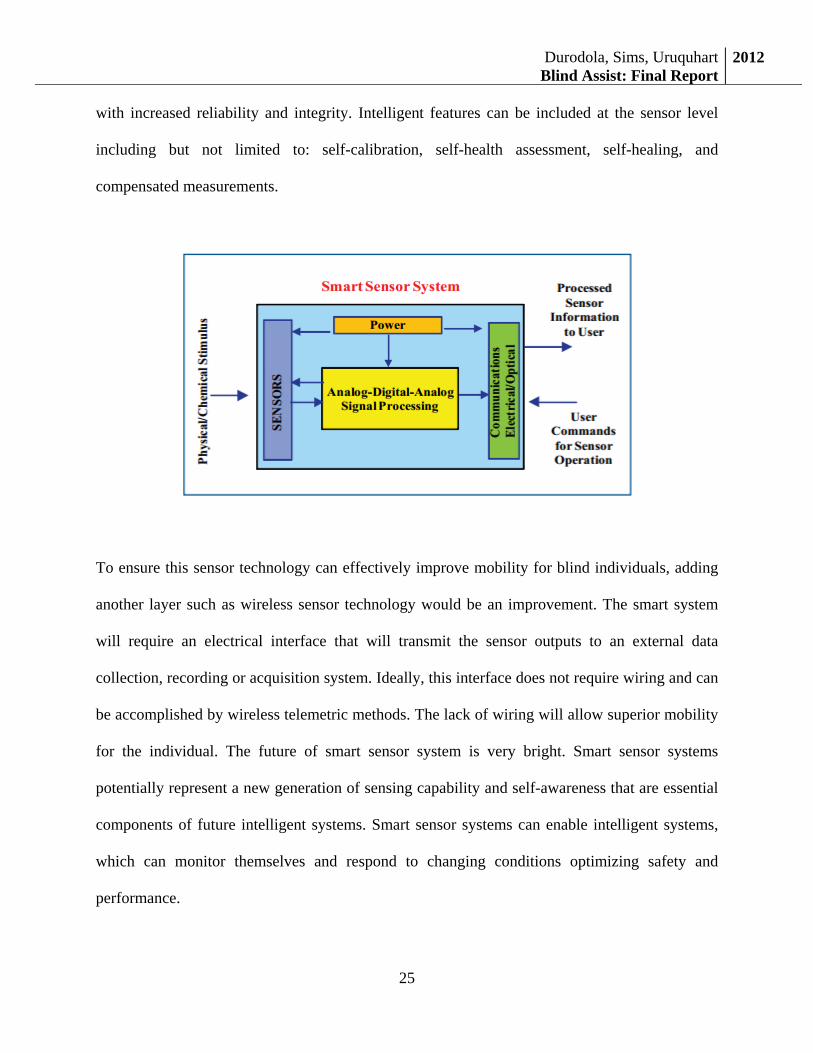
of a smart sensor is that the integration of silicon microprocessors with sensor technology can
not only provide interpretive power and customized outputs, but also significantly improve
sensor system performance and capabilities. Several functional layers of smart sensor exist:
signal processing, data validation and interpretation, and signal transmission and display.
Multiple sensors can be included in a single smart sensor system whose operating properties,
such as bias voltage or temperature can be set by the microprocessor. The sensor elements
interface to signal control and conditioning stages that will provide both excitation and signal
data logging and conditioning. The data acquisition layer will convert the signal from analog to
digital and acquire additional parameters of interest to provide compensation when needed for
thermal drift, long term drift, etc. There are plenty of uses for this system in the digital world.
Sensor inputs can be processed to reduce noise, integrated with other sensory inputs for
compensation, redundancy, and reliability improvements, and then interfaced to output
requirements that range from simple digital displays of sensor outputs to wirelessly transmitted
and stored data that feed-back to sensors or feed-forward to appropriate system controls.
This system will definitely improve our blind assist model. Using smart sensor will allow
versatility and ease of use interface due to the fact that the smart sensor will be handling most of
the input devices that will allow for easy integration of complete system. The smart system also
has capabilities to perform wirelessly. The smart sensor system will require an electrical
interface that will transmit the sensor outputs to an external data collection, recording or
acquisition system. Ideally, this interface does not require wiring and can be accompanied by
wireless telemetric methods. This system can also function as a noise cancelling device to allow
the user to fully concentrate on the instructions rather than being obstructed by outside noise.
One major implication of smart sensor system is that important data can be provided to the user
Durodola, Sims, UruquhartBlind Assist: Final Report
2012
25
with increased reliability and integrity. Intelligent features can be included at the sensor level
including but not limited to: self-calibration, self-health assessment, self-healing, and
compensated measurements.
To ensure this sensor technology can effectively improve mobility for blind individuals, adding
another layer such as wireless sensor technology would be an improvement. The smart system
will require an electrical interface that will transmit the sensor outputs to an external data
collection, recording or acquisition system. Ideally, this interface does not require wiring and can
be accomplished by wireless telemetric methods. The lack of wiring will allow superior mobility
for the individual. The future of smart sensor system is very bright. Smart sensor systems
potentially represent a new generation of sensing capability and self-awareness that are essential
components of future intelligent systems. Smart sensor systems can enable intelligent systems,
which can monitor themselves and respond to changing conditions optimizing safety and
performance.
Durodola, Sims, UruquhartBlind Assist: Final Report
2012
26
An item that could be removed from this system to improve the robustness of this system is the
keypad. With the key pad configuration there is a amount of accidental button pressing causing
the system to uses function that aren’t needed at the time or turn off function that are need. In
addition, we would add a better voice recognition software to the system which would also make
the key pad obsolete. Another option is to move the key pads functionality to the Braille key
board for manual input. The Braille keyboard would perform double duties as a function enabler
and manual input device as well. The reliability of the system would be improved with the
deletion of the keyboard because it can eliminate unnecessary entries causing errors.
Using a long lasting battery will ensure the user remains autonomous because they will be able to
utilize the device for longer periods of time. The current device utilizes a nickel metal hydride
“NIMH” battery that is 12 volt, 3 amp, and has approximately 1.5 hours of usage. Using a
lithium ion battery would have significant improvements in the following areas:
• The weight of the battery will be reduced
• Consume more power because the lithium batteries store more amp hours in a smaller
envelope so we can use it longer.
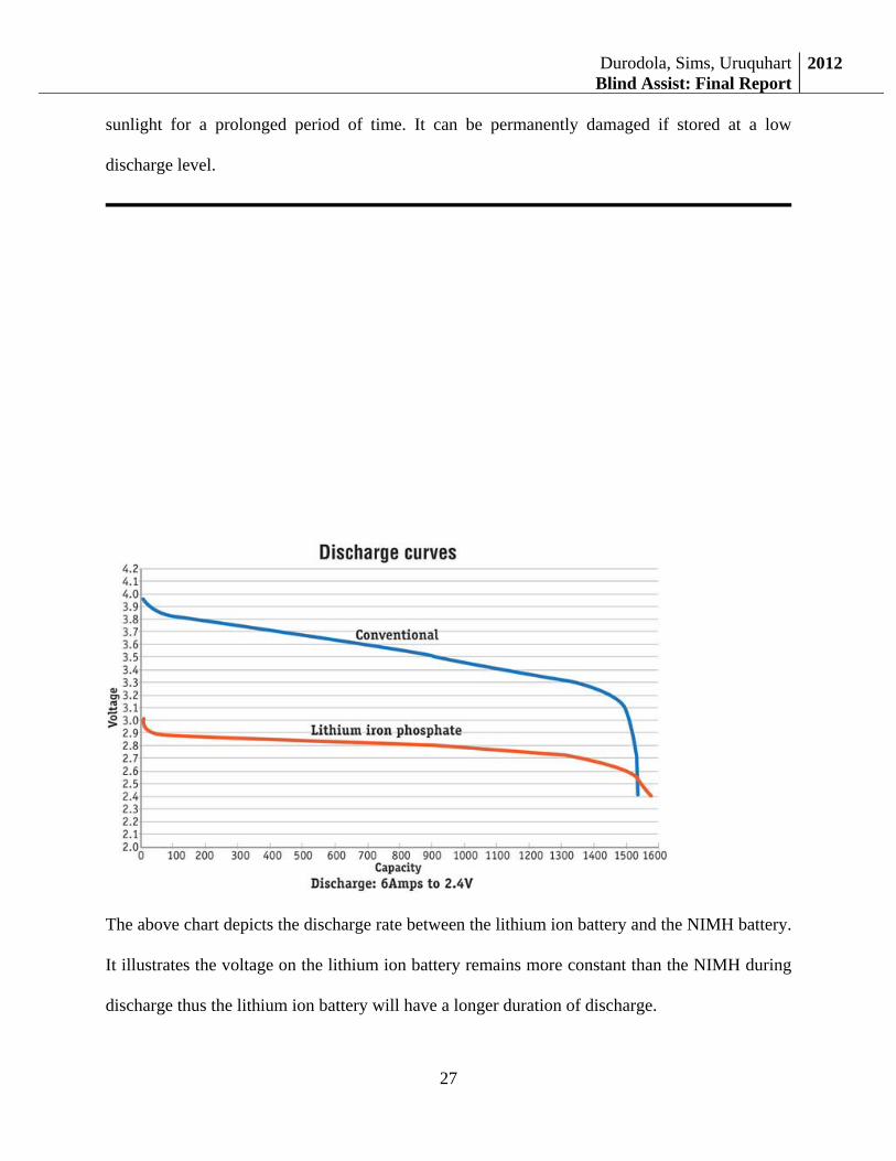
Lithium ion batteries are a newer type of battery and are the best choice for this application
because they have the best energy to weight ratio, no memory effect, slow to lose its charge
when not in use. Some of the advantages of lithium battery are the high performance in cold
weather making it ideal for winter outdoor use. It has a better life cycle than the NIMH battery so
the batteries will last longer. It has a more rapid charging time so there is less waiting time for
the next use. Some disadvantages are its tendency to explode due to high heat exposure or direct
Durodola, Sims, UruquhartBlind Assist: Final Report
2012
27
sunlight for a prolonged period of time. It can be permanently damaged if stored at a low
discharge level.
The above chart depicts the discharge rate between the lithium ion battery and the NIMH battery.
It illustrates the voltage on the lithium ion battery remains more constant than the NIMH during
discharge thus the lithium ion battery will have a longer duration of discharge.
Durodola, Sims, UruquhartBlind Assist: Final Report
2012
28
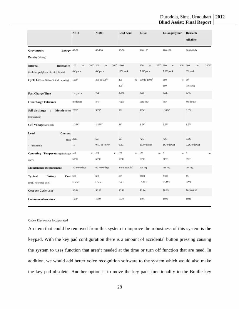
Cadex Electronics Incorporated
An item that could be removed from this system to improve the robustness of this system is the
keypad. With the key pad configuration there is a amount of accidental button pressing causing
the system to uses function that aren’t needed at the time or turn off function that are need. In
addition, we would add better voice recognition software to the system which would also make
the key pad obsolete. Another option is to move the key pads functionality to the Braille key
NiCd NiMH Lead Acid Li-ion Li-ion polymer Reusable
Alkaline
Gravimetric Energy
Density(Wh/kg)
45-80 60-120 30-50 110-160 100-130 80 (initial)
Internal Resistance
(includes peripheral circuits) in mW
100 to 2001
6V pack
200 to 3001
6V pack
<1001
12V pack
150 to 2501
7.2V pack
200 to 3001
7.2V pack
200 to 20001
6V pack
Cycle Life (to 80% of initial capacity) 15002 300 to 5002,3 200 to
3002
500 to 10003 300 to
500
503
(to 50%)
Fast Charge Time 1h typical 2-4h 8-16h 2-4h 2-4h 2-3h
Overcharge Tolerance moderate low High very low low Moderate
Self-discharge / Month (room
temperature)
20%4 30%4 5% 10%5 ~10%5 0.3%
Cell Voltage(nominal) 1.25V6 1.25V6 2V 3.6V 3.6V 1.5V
Load Current
- peak
- best result
20C
1C
5C
0.5C or lower
5C7
0.2C
>2C
1C or lower
>2C
1C or lower
0.5C
0.2C or lower
Operating Temperature(discharge
only)
-40 to
60°C
-20 to
60°C
-20 to
60°C
-20 to
60°C
0 to
60°C
0 to
65°C
Maintenance Requirement 30 to 60 days 60 to 90 days 3 to 6 months9 not req. not req. not req.
Typical Battery Cost
(US$, reference only)
$50
(7.2V)
$60
(7.2V)
$25
(6V)
$100
(7.2V)
$100
(7.2V)
$5
(9V)
Cost per Cycle(US$)11 $0.04 $0.12 $0.10 $0.14 $0.29 $0.10-0.50
Commercial use since 1950 1990 1970 1991 1999 1992
Durodola, Sims, UruquhartBlind Assist: Final Report
2012
29
board for manual input. The Braille keyboard would perform double duties as a function enabler
and manual input device as well. The reliability of the system would be improved with the
deletion of the keyboard because it can eliminate unnecessary entries causing errors.
The above additions and deletions will enhance the device by allowing the individual ease of
usage, prolonged usage with a better battery option, and more autonomy with wireless smart
sensor technology. Without the key pad, there will be fewer instances of accidental
activations/reactivations because the key pad is located inside of a pouch area and can be easily
depressed and activated. The lithium ion battery offers more battery life with less weight adding
to the portability of this system. Without these sensors being hard wired to the system, there is
less chance of interference or damage due to the fact that the wires are present. Additional
funding and research will be necessary to procure the items to upgrade the device.
8.NomenclatureGlossary
GPS – Global Positioning System
BOSS – The head program that runs the entire project. Sub programs are called from here.
Sun SPOT - (Sun Small Programmable Object Technology) is a wireless sensor network (WSN)
developed by Sun Microsystems
WSN – Wireless Sensor Network
9.Conclusion
In conclusion, this was an excellent design experience, we learned a lot as a team and as
individuals. We believe with the recommendations highlighted above, we can create a
commercial device that can assist visually impaired individuals with mobility.
Durodola, Sims, UruquhartBlind Assist: Final Report
2012
30
10.Acknowledgements
We want to appreciate all the help and support we have received from the Intel Cup
competition organizers. We are also grateful to our advisor, Dr Charles Kim and members of the
Senior Desgin I & II at Howard University.
11.References1] NFB - Home. Web. 08 Oct. 2011. <http://www.nfb.org/nfb/default.asp>. [2] "WHO | Visual Impairment and Blindness." Web. 09 Oct. 2011. <http://www.who.int/mediacentre/factsheets/fs282/en/>. [3] "Computer Vision Software » Blog Archive » USD Banknotes Recognition." Computer Vision Software. Web. 08 Oct. 2011. <http://www.computer-vision-software.com/blog/2009/12/usd-banknotes-recognition/>. [4] Bradski, Gary R., and Adrian Kaehler. Learning OpenCV: [computer Vision with the OpenCV Library]. Sebastopol: O'Reilly, 2008. Print. [5] Corporation, Parallax. "PING)))™ Ultrasonic Distance Sensor (#28015)." www.parallax.com, 11 Sept. 2009. Web. 08 Oct. 2011. [6] Freescale Semiconductor. "Ultrasonic Distance Measurer Implemented with the MC9RS08KA2." 2008. Web. 08 Oct. 2011. [7] Borenstein, J. Real-time Obstacle Avoidance for Fast Mobile Robots in Cluttered Environments. IEEE, 18 May 1990. Web. 08 Oct. 2011. [8] L. E. Kinsler and A. R. Frey, Fundamentals of Acoustics, 2nd ed. (New York: John Wiley & Sons, 1962). [9] LaPierre, Charles. Personal Navigation System for the Visually Impaired. Ontario, Canada. Carleton University. 1998. Other un-cited References Johnson, Dee laMont .”Computers in the special education classroom”, Psychology press 1987, p57. Ravindra, Thamma. Theory and prediction of position error for automated guided vehicles with ultrasonic sensing based on time-of-flight theory. ProQuest, 2004. 97.
Durodola, Sims, UruquhartBlind Assist: Final Report
2012
31
Calvert, J.B. "Sound Waves." Sound Waves. 6 May 2000. Web. 14 Oct. 2011. <http://mysite.du.edu/~jcalvert/waves/soundwav.htm>. Gissurarson, Gisli. "Ultrasound Distance Measurement and Ultrasonic Doppler Effect."Ultrasonic Industrial Positioning Systems, and Ranging. Web. 08 Oct. 2011. <http://www.hexamite.com/hetheory.htm>. Jernej Mrovlje and Damir Vrancic “Distance measuring based on stereoscopic pictures”, presented at the 9th International PhD Workshop on Systems and Control: Young Generation Viewpoint, Izola, Slovenia, 2008 Resources
L. Schwiebert, S. k. S. Gupta, and J. Weinmann, Research Challenges in Wireless Networks of Biomedical Sensors, in 7th annual International Conference on Mobile Computing and Networking, Rome, Italy, 2001, pp. 151-165.
Hunter, et al. Smart Sensor Systems. The Electrochemical Society Interface. http://www.electrochem.org/dl/interface/wtr/wtr10/wtr10_p029-034.pdf
Neves, et al. Applications of Wireless Sensor Networks to Healthcare Promotion. http://repositorio.ipcb.pt/bitstream/10400.11/548/1/JCOMSS_2009.pdf
http://iccnexergy.com/articles/1256/iron-phosphate-builds-a-better-battery/ Buchmann,Isidor. Cadex Electronics Inc. www.buchmann.ca.
http://www.buchmann.ca/Article4-Page1.asp [patent] http://www.patentstorm.us/patents/5687136.html
12.Appendix
12.1TechnicalDocumentation:The BlindAssist consists of two major functionalities to aid in avoiding obstacles, Obstacle Avoidance, and providing directions to a particular location using GPS, Directions to Location. In this technical documentation, we will cover the following:
• Obstacle Alert o Ultrasonic sensor o Arduino microcontroller o Serial communication o Processing o Sun Spots micro processors
• Directions to location • Overhead program (‘BOSS’)
o Polling and Keypad o Threading and cancelling threads o Getting system status: Internet and time o Text-to-Speech o Starting up program on booting the intel board
Durodola, Sims, UruquhartBlind Assist: Final Report
2012
32
12.1.1ObstacleAlertWe will describe the different components and software used to achieve the obstacle alert function
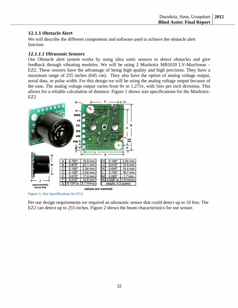
12.1.1.1UltrasonicSensorsOur Obstacle alert system works by using ultra sonic sensors to detect obstacles and give feedback through vibrating modules. We will be using 2 Maxbotix MB1020 LV-MaxSonar –EZ2. These sensors have the advantage of being high quality and high precision. They have a maximum range of 255 inches (645 cm). They also have the option of analog voltage output, serial data, or pulse width. For this design we will be using the analog voltage output because of the ease. The analog voltage output varies from 0v to 1.275v, with 5mv per inch divisions. This allows for a reliable calculation of distance. Figure 1 shows size specifications for the Maxbotix- EZ2
Figure 1: Size Specifications for EV2
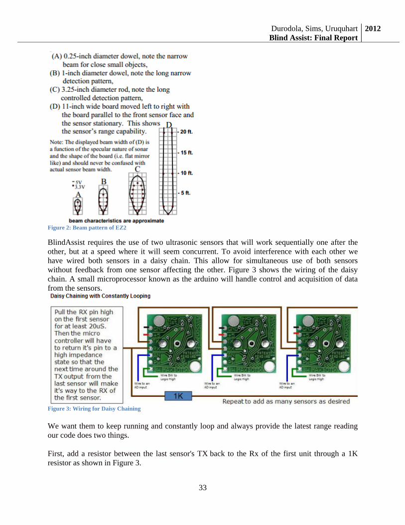
Per our design requirements we required an ultrasonic sensor that could detect up to 10 feet. The EZ2 can detect up to 255 inches. Figure 2 shows the beam characteristics for our sensor.
Durodola, Sims, UruquhartBlind Assist: Final Report
2012
33
Figure 2: Beam pattern of EZ2
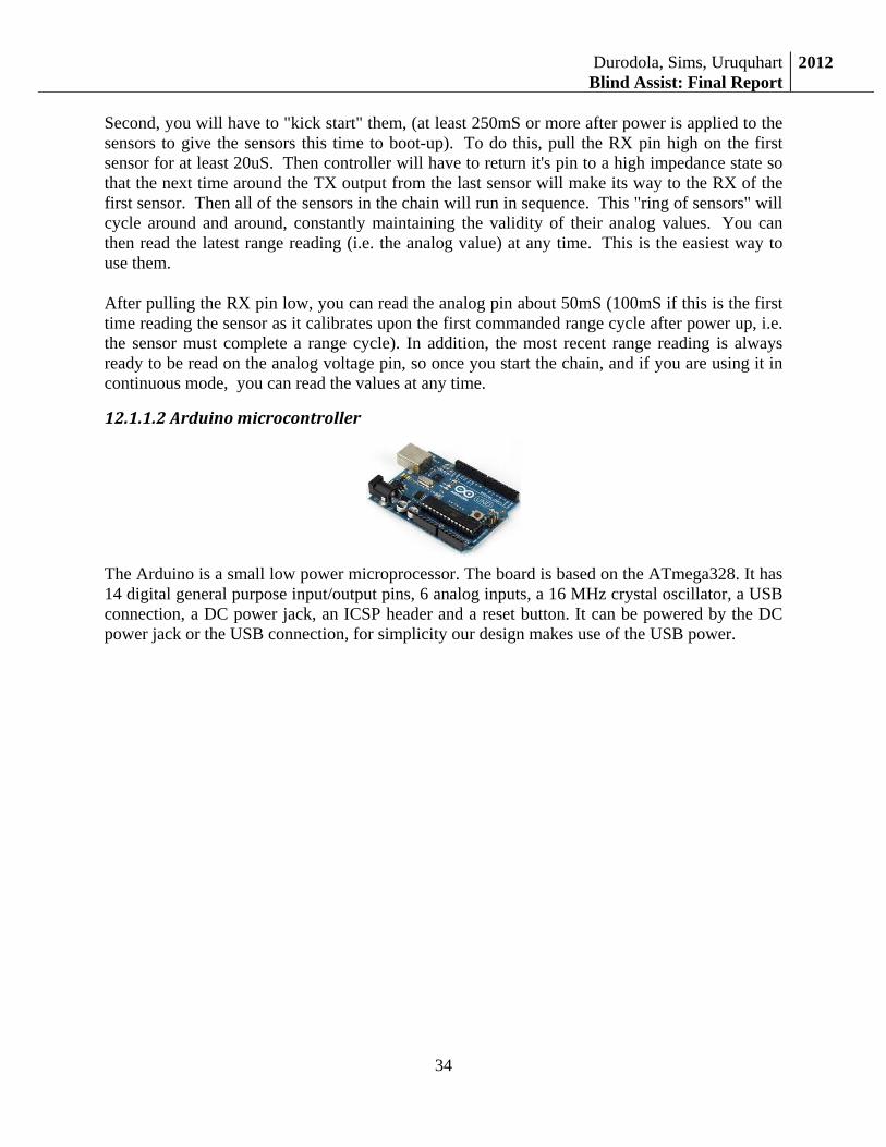
BlindAssist requires the use of two ultrasonic sensors that will work sequentially one after the other, but at a speed where it will seem concurrent. To avoid interference with each other we have wired both sensors in a daisy chain. This allow for simultaneous use of both sensors without feedback from one sensor affecting the other. Figure 3 shows the wiring of the daisy chain. A small microprocessor known as the arduino will handle control and acquisition of data from the sensors.
Figure 3: Wiring for Daisy Chaining
We want them to keep running and constantly loop and always provide the latest range reading our code does two things.
First, add a resistor between the last sensor's TX back to the Rx of the first unit through a 1K resistor as shown in Figure 3.
Durodola, Sims, UruquhartBlind Assist: Final Report
2012
34
Second, you will have to "kick start" them, (at least 250mS or more after power is applied to the sensors to give the sensors this time to boot-up). To do this, pull the RX pin high on the first sensor for at least 20uS. Then controller will have to return it's pin to a high impedance state so that the next time around the TX output from the last sensor will make its way to the RX of the first sensor. Then all of the sensors in the chain will run in sequence. This "ring of sensors" will cycle around and around, constantly maintaining the validity of their analog values. You can then read the latest range reading (i.e. the analog value) at any time. This is the easiest way to use them.
After pulling the RX pin low, you can read the analog pin about 50mS (100mS if this is the first time reading the sensor as it calibrates upon the first commanded range cycle after power up, i.e. the sensor must complete a range cycle). In addition, the most recent range reading is always ready to be read on the analog voltage pin, so once you start the chain, and if you are using it in continuous mode, you can read the values at any time.
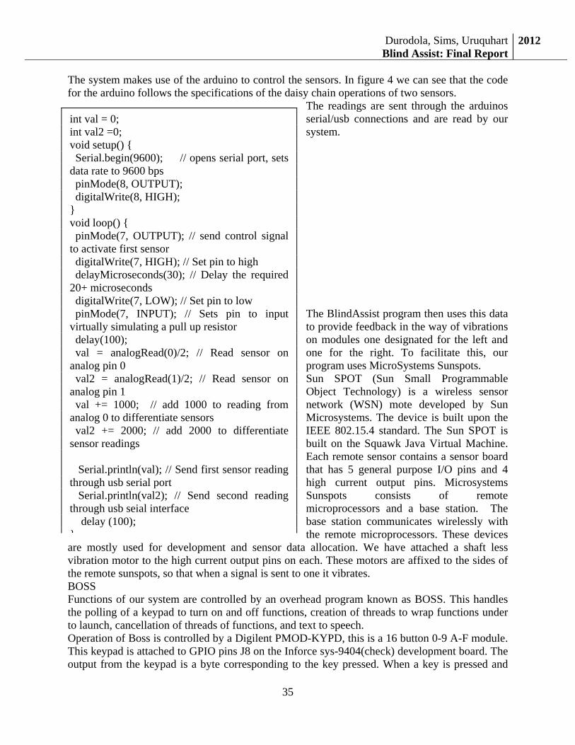
12.1.1.2Arduinomicrocontroller
The Arduino is a small low power microprocessor. The board is based on the ATmega328. It has 14 digital general purpose input/output pins, 6 analog inputs, a 16 MHz crystal oscillator, a USB connection, a DC power jack, an ICSP header and a reset button. It can be powered by the DC power jack or the USB connection, for simplicity our design makes use of the USB power.
Durodola, Sims, UruquhartBlind Assist: Final Report
2012
35
The system makes use of the arduino to control the sensors. In figure 4 we can see that the code for the arduino follows the specifications of the daisy chain operations of two sensors.
The readings are sent through the arduinos serial/usb connections and are read by our system. The BlindAssist program then uses this data to provide feedback in the way of vibrations on modules one designated for the left and one for the right. To facilitate this, our program uses MicroSystems Sunspots. Sun SPOT (Sun Small Programmable Object Technology) is a wireless sensor network (WSN) mote developed by Sun Microsystems. The device is built upon the IEEE 802.15.4 standard. The Sun SPOT is built on the Squawk Java Virtual Machine. Each remote sensor contains a sensor board that has 5 general purpose I/O pins and 4 high current output pins. Microsystems Sunspots consists of remote microprocessors and a base station. The base station communicates wirelessly with the remote microprocessors. These devices
are mostly used for development and sensor data allocation. We have attached a shaft less vibration motor to the high current output pins on each. These motors are affixed to the sides of the remote sunspots, so that when a signal is sent to one it vibrates. BOSS Functions of our system are controlled by an overhead program known as BOSS. This handles the polling of a keypad to turn on and off functions, creation of threads to wrap functions under to launch, cancellation of threads of functions, and text to speech. Operation of Boss is controlled by a Digilent PMOD-KYPD, this is a 16 button 0-9 A-F module. This keypad is attached to GPIO pins J8 on the Inforce sys-9404(check) development board. The output from the keypad is a byte corresponding to the key pressed. When a key is pressed and
int val = 0; int val2 =0; void setup() { Serial.begin(9600); // opens serial port, sets data rate to 9600 bps pinMode(8, OUTPUT); digitalWrite(8, HIGH); } void loop() { pinMode(7, OUTPUT); // send control signal to activate first sensor digitalWrite(7, HIGH); // Set pin to high delayMicroseconds(30); // Delay the required 20+ microseconds digitalWrite(7, LOW); // Set pin to low pinMode(7, INPUT); // Sets pin to input virtually simulating a pull up resistor delay(100); val = analogRead(0)/2; // Read sensor on analog pin 0 val2 = analogRead(1)/2; // Read sensor on analog pin 1 val += 1000; // add 1000 to reading from analog 0 to differentiate sensors val2 += 2000; // add 2000 to differentiate sensor readings Serial.println(val); // Send first sensor reading through usb serial port Serial.println(val2); // Send second reading through usb seial interface delay (100); }
Durodola, Sims, UruquhartBlind Assist: Final Report
2012
36
released we read this byte and relate this to a corresponding function. We put this function in a loop to constantly check for key presses. Our solution takes advantage of multithreading in that each functionality is launched in its own thread. We us POSIX threads since we are programming BOSS in c/c++ and we create a thread that launches a functionality such as obstacle avoidance. When we launch a new thread we receive a thread handler, this thread handler is needed in order for us to cancel and destroy the respective thread when required. A key function of our system is that is gives its user time and status of the system updates when requested. We use a series of functions to get the current time and status of the internet , and output is pushed to a text to speech program that allows for strings to be converted to audio speech. Our text to speech modules utilizes Freetts. FreeTTS is an open source speech synthesis system written entirely in the Java programming language. It is based upon Flite. FreeTTS is an implementation of Sun's Java Speech API. Being that this is a java implantation we simple run the module with a string as an parameter in its run. To output the time our system uses a Linux system command “ Java –jar TexttoSpeech.jar “9:30””. This allows easy implementation of a text to speech functionality. Finally we have set BOSS to run at start up. This will allow for us to function the system without having to connect into the system by either serial of ssh. So once the system starts up our program will begin running.
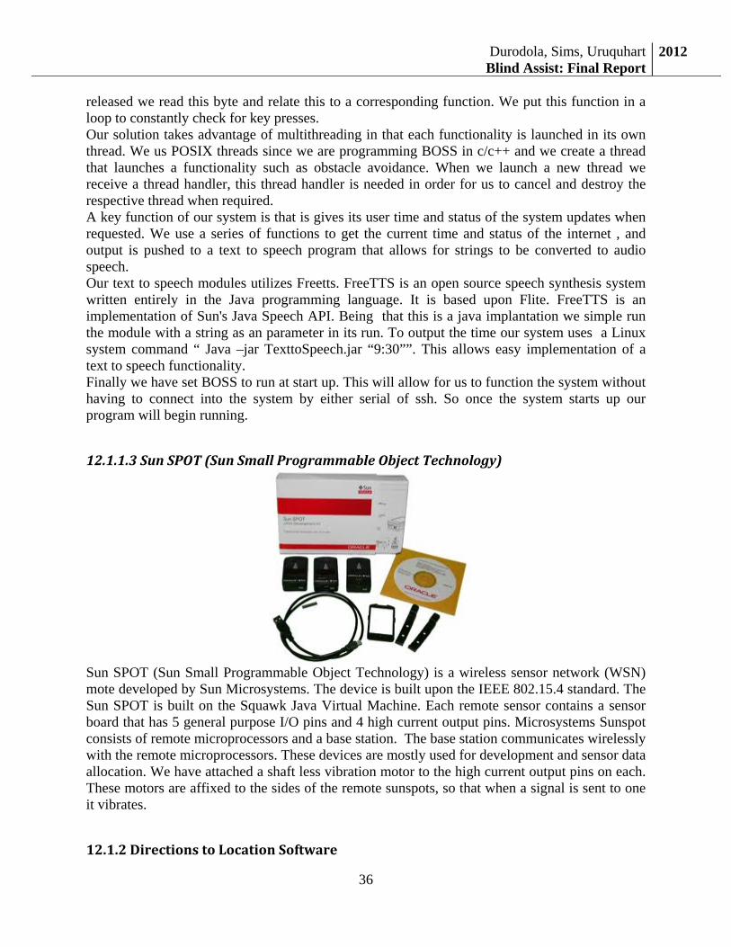
12.1.1.3SunSPOT(SunSmallProgrammableObjectTechnology)
Sun SPOT (Sun Small Programmable Object Technology) is a wireless sensor network (WSN) mote developed by Sun Microsystems. The device is built upon the IEEE 802.15.4 standard. The Sun SPOT is built on the Squawk Java Virtual Machine. Each remote sensor contains a sensor board that has 5 general purpose I/O pins and 4 high current output pins. Microsystems Sunspot consists of remote microprocessors and a base station. The base station communicates wirelessly with the remote microprocessors. These devices are mostly used for development and sensor data allocation. We have attached a shaft less vibration motor to the high current output pins on each. These motors are affixed to the sides of the remote sunspots, so that when a signal is sent to one it vibrates.
12.1.2DirectionstoLocationSoftware
Durodola, Sims, UruquhartBlind Assist: Final Report
2012
37
The Directions to Location feature allows the user to travel to any destination that they would like to walk to. Technologies used:
• Java v6
• Free TTS API
• Google Directions API
• Google Places API
• Google Geocode API
• Gson API
• GPS Dongle
Features:
• Turn by turn walking directions to a desired destination upon request
• Multiple address options to ensure destination accuracy
• Text To Speech to portray results to visually impaired user
• Can handle generic ambiguous destination input (i.e. Food, Wal-Mart)
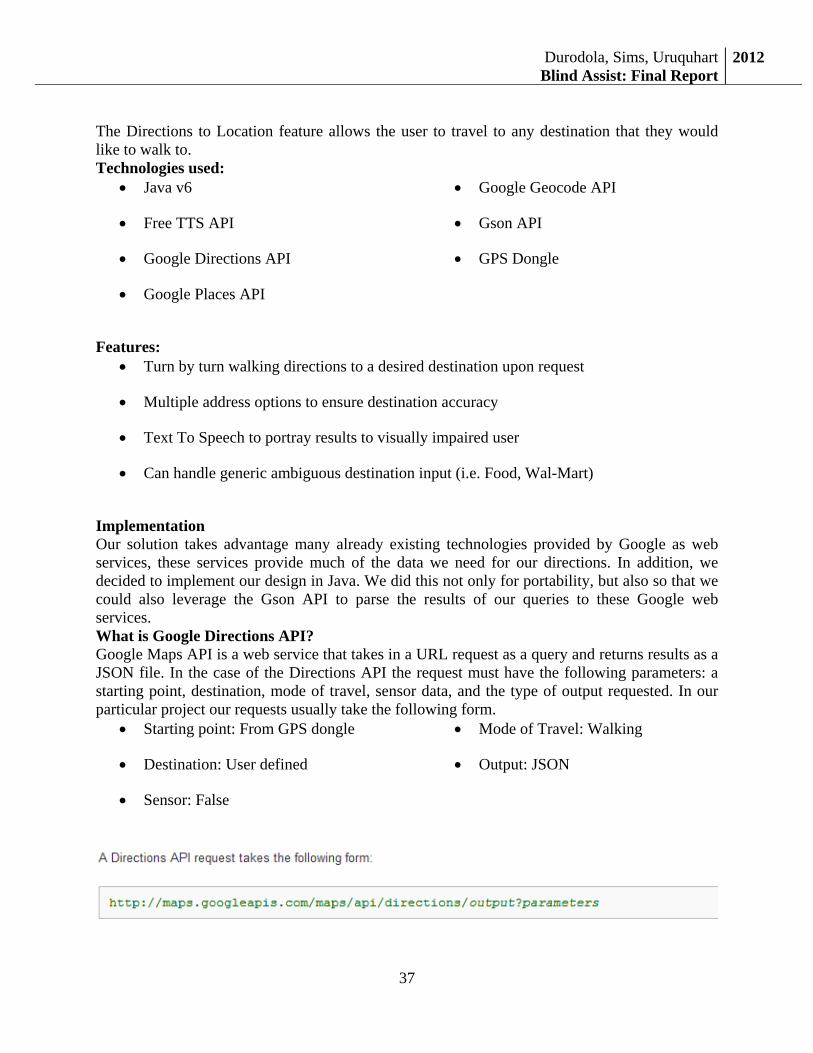
Implementation Our solution takes advantage many already existing technologies provided by Google as web services, these services provide much of the data we need for our directions. In addition, we decided to implement our design in Java. We did this not only for portability, but also so that we could also leverage the Gson API to parse the results of our queries to these Google web services. What is Google Directions API? Google Maps API is a web service that takes in a URL request as a query and returns results as a JSON file. In the case of the Directions API the request must have the following parameters: a starting point, destination, mode of travel, sensor data, and the type of output requested. In our particular project our requests usually take the following form.
• Starting point: From GPS dongle
• Destination: User defined
• Sensor: False
• Mode of Travel: Walking
• Output: JSON
Durodola, Simms, Urquhart Blind Assist: Project Final Report
38
Page38!
We send our request from within our program using a Java URL request. Then we cast that URL type to an HttpURLConnection type and open the connection. Next we connect to the server and send the request. The output of this request is returned in the JSON format, which is shown below. However in our program we do not display the results. { "status": "OK", "routes": [ { "summary": "I-40 W", "legs": [ { "steps": [ { "travel_mode": "DRIVING", "start_location": { "lat": 41.8507300, "lng": -87.6512600 }, "end_location": { "lat": 41.8525800, "lng": -87.6514100 }, "polyline": { "points": "a~l~Fjk~uOwHJy@P" }, "duration": { "value": 19, "text": "1 min" }, "html_instructions": "Head \u003cb\u003enorth\u003c/b\u003e on \u003cb\u003eS Morgan St\u003c/b\u003e toward \u003cb\u003eW Cermak Rd\u003c/b\u003e", "distance": { "value": 207, "text": "0.1 mi" } }, ... ... additional steps of this leg ... ... additional legs of this route
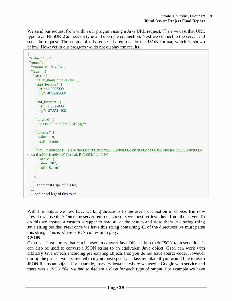
With this output we now have walking directions to the user’s destination of choice. But now how do we use this? Once the server returns its results we must retrieve them from the server. To do this we created a custom scrapper to read all of the results and store them in a string using Java string builder. Next once we have this string containing all of the directions we must parse this string. This is where GSON comes in to play. GSON Gson is a Java library that can be used to convert Java Objects into their JSON representation. It can also be used to convert a JSON string to an equivalent Java object. Gson can work with arbitrary Java objects including pre-existing objects that you do not have source-code. However during the project we discovered that you must specify a class template if you would like to use a JSON file as an object. For example, in every instance where we used a Google web service and there was a JSON file, we had to declare a class for each type of output. For example we have
Durodola, Simms, Urquhart Blind Assist: Project Final Report
39
Page39!
classes for AddressType, DirectionsType, and PlacesType. Each of these classes represents the result from a request we send to the Google web server except in Java Object form. A snippet from the DirectionsType is pictured below:
Once we have this specification we will then use the GSON API to convert the string containing the directions to an object of this class type. Again similar methods are used with the Places API and the Geocode API. The code that performs this transformation is as follows.
This is the most important line of code in our program! It allows us to manipulate the directions results in any way that we want. And now that we have the directions we need to portray them to the user. This is where the users experience in the directions comes in to play. Directions We are now at the point where we have retrieved the results and we are ready to guide the user to their destination. When the directions start, the first thing the user hears in the ending location and the starting location. Next thing they hear is the distance of the trip and the duration of the trip. Then the directions start.
12.1.3“BOSS”(Overheadsoftware)
Durodola, Simms, Urquhart Blind Assist: Project Final Report
40
Page40!
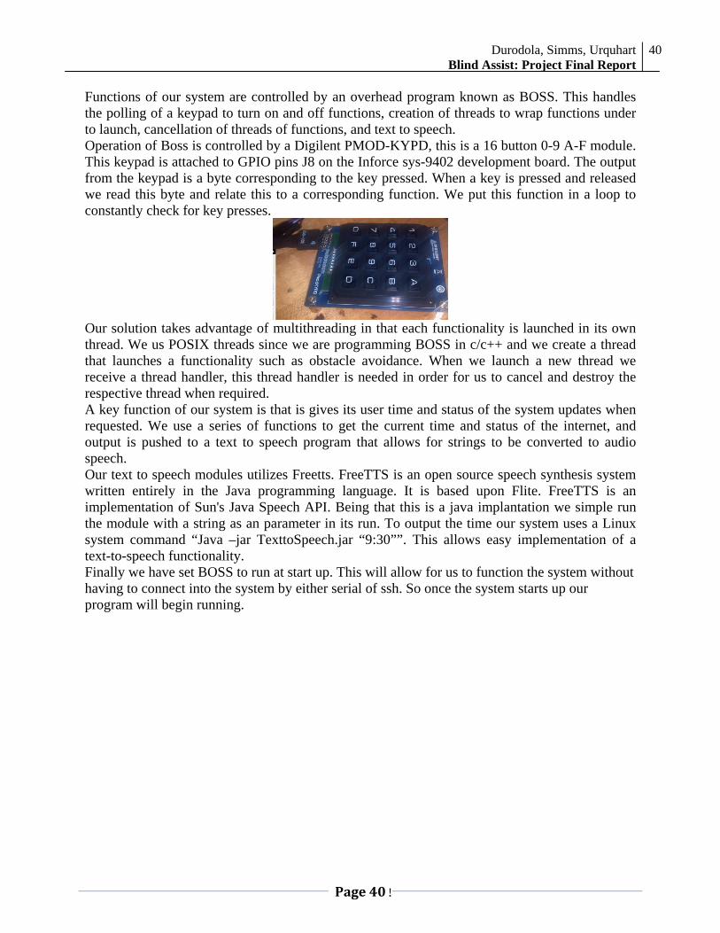
Functions of our system are controlled by an overhead program known as BOSS. This handles the polling of a keypad to turn on and off functions, creation of threads to wrap functions under to launch, cancellation of threads of functions, and text to speech. Operation of Boss is controlled by a Digilent PMOD-KYPD, this is a 16 button 0-9 A-F module. This keypad is attached to GPIO pins J8 on the Inforce sys-9402 development board. The output from the keypad is a byte corresponding to the key pressed. When a key is pressed and released we read this byte and relate this to a corresponding function. We put this function in a loop to constantly check for key presses.
Our solution takes advantage of multithreading in that each functionality is launched in its own thread. We us POSIX threads since we are programming BOSS in c/c++ and we create a thread that launches a functionality such as obstacle avoidance. When we launch a new thread we receive a thread handler, this thread handler is needed in order for us to cancel and destroy the respective thread when required. A key function of our system is that is gives its user time and status of the system updates when requested. We use a series of functions to get the current time and status of the internet, and output is pushed to a text to speech program that allows for strings to be converted to audio speech. Our text to speech modules utilizes Freetts. FreeTTS is an open source speech synthesis system written entirely in the Java programming language. It is based upon Flite. FreeTTS is an implementation of Sun's Java Speech API. Being that this is a java implantation we simple run the module with a string as an parameter in its run. To output the time our system uses a Linux system command “Java –jar TexttoSpeech.jar “9:30””. This allows easy implementation of a text-to-speech functionality. Finally we have set BOSS to run at start up. This will allow for us to function the system without having to connect into the system by either serial of ssh. So once the system starts up our program will begin running.


![David Pickett [Volvo Car Australia]; [National Road … · Park Assist Pilot Rear radar sensors • Blind Spot Information System • Lane Change/Merge Assist • Cross Traffic Alert](https://img.dokumen.tips/doc/110x75/5b7401097f8b9ae54f8e7174/david-pickett-volvo-car-australia-national-road-park-assist-pilot-rear-radar.jpg)