Embed Size (px)
Citation preview
IAEI NEWS July . August 2010 www.iaei.org
SELECTIVE COORDINATION ENFORCEMENT
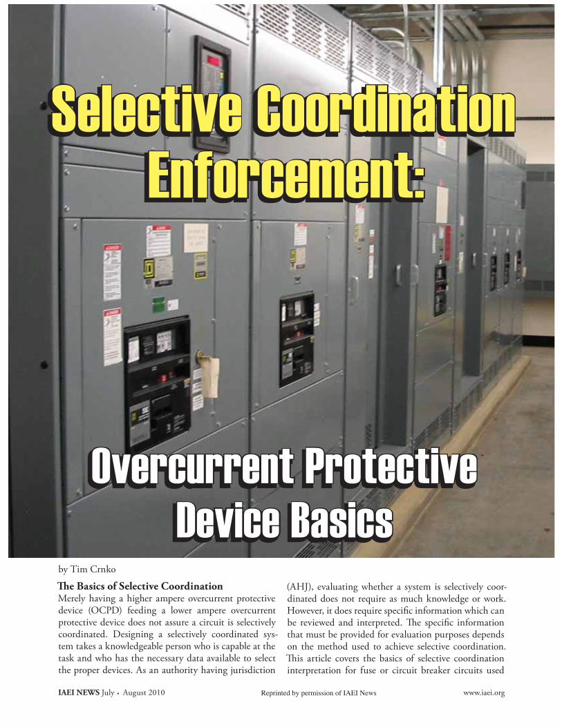
Merely having a higher ampere overcurrent protective device (OCPD) feeding a lower ampere overcurrent protective device does not assure a circuit is selectively coordinated. Designing a selectively coordinated sys-tem takes a knowledgeable person who is capable at the task and who has the necessary data available to select the proper devices. As an authority having jurisdiction
(AHJ), evaluating whether a system is selectively coor-dinated does not require as much knowledge or work. However, it does require specific information which can
that must be provided for evaluation purposes depends on the method used to achieve selective coordination.
interpretation for fuse or circuit breaker circuits used
by Tim Crnko
Selective CoordinationEnforcement:
Overcurrent ProtectiveDevice Basics
Selective CoordinationEnforcement:
Overcurrent ProtectiveDevice Basics
Reprinted by permission of IAEI News
www.iaei.org July . August 2010 IAEI NEWS
SELECTIVE COORDINATION ENFORCEMENT
in 600 V or less systems. It is not a comprehensive cov-erage, but should help the AHJ request the necessary documentation and facilitate checking. For more in-depth materials see the end of the article, “Additional Resources” section.
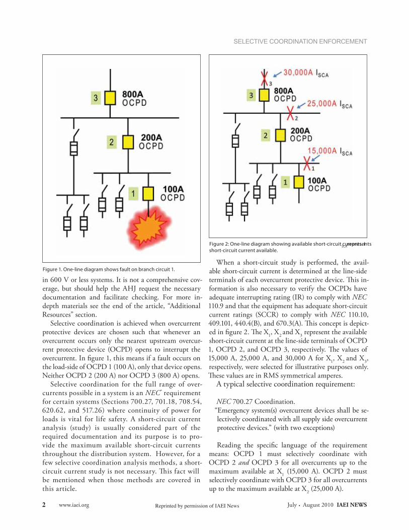
Selective coordination is achieved when overcurrent protective devices are chosen such that whenever an overcurrent occurs only the nearest upstream overcur-rent protective device (OCPD) opens to interrupt the overcurrent. In figure 1, this means if a fault occurs on the load-side of OCPD 1 (100 A), only that device opens. Neither OCPD 2 (200 A) nor OCPD 3 (800 A) opens.
Selective coordination for the full range of over-currents possible in a system is an NEC ® requirement for certain systems (Sections 700.27, 701.18, 708.54, 620.62, and 517.26) where continuity of power for loads is vital for life safety. A short-circuit current analysis (study) is usually considered part of the required documentation and its purpose is to pro-vide the maximum available short-circuit currents throughout the distribution system. However, for a few selective coordination analysis methods, a short-circuit current study is not necessary. This fact will be mentioned when those methods are covered in this article.
When a short-circuit study is performed, the avail-able short-circuit current is determined at the line-side
-formation is also necessary to verify the OCPDs have adequate interrupting rating (IR) to comply with NEC 110.9 and that the equipment has adequate short-circuit current ratings (SCCR) to comply with NEC 110.10,
-1, X2 and X3 represent the available
short-circuit current at the line-side terminals of OCPD
15,000 A, 25,000 A, and 30,000 A for X1, X2 and X3, respectively, were selected for illustrative purposes only.
symmetrical amperes.A typical selective coordination requirement:
NEC 700.27 Coordination.“Emergency system(s) overcurrent devices shall be se-lectively coordinated with all supply side overcurrent protective devices.” (with two exceptions)
Reading the specific language of the requirement means: OCPD 1 must selectively coordinate with OCPD 2 and OCPD 3 for all overcurrents up to the maximum available at X1 (15,000 A). OCPD 2 must selectively coordinate with OCPD 3 for all overcurrents up to the maximum available at X2 (25,000 A).
Figure 1. One-line diagram shows fault on branch circuit 1.
Figure 2: One-line diagram showing available short-circuit currents. ISCA represents short-circuit current available.
Reprinted by permission of IAEI News2
IAEI NEWS July . August 2010 www.iaei.org
SELECTIVE COORDINATION ENFORCEMENT
Selective Coordination Utilizing Fuses--
proaches: a. Fuse manufacturer’s published selectivity ampere rating ratiosb. Interpret time-current curves
Example a: Fuse Selectivity Ampere Rating Ratios
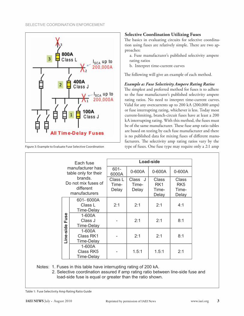
to the fuse manufacturer’s published selectivity ampere rating ratios. No need to interpret time-current curves. Valid for any overcurrents up to 200 kA (200,000 amps) or fuse interrupting rating, whichever is less. Today most current-limiting, branch-circuit fuses have at least a 200 kA interrupting rating. With this method, the fuses must
are based on testing by each fuse manufacturer and there is no published data for mixing fuses of different manu-
type of fuses. One fuse type may require only a 2:1 amp Figure 3: Example to Evaluate Fuse Selective Coordination
Table 1: Fuse Selectivity Amp Rating Ratio Guide
Each fuse manufacturer has table only for their
brands. Do not mix fuses of
different manufacturers
Load-side
601-6000A
0-600A 0-600A 0-600A
Class L Time-Delay
Class JTime-Delay
Class RK1
Time-Delay
Class RK5
Time-Delay
Lin
e-si
de
Fu
se
601- 6000A Class L
Time-Delay 2:1 2:1 2:1 4:1
1-600A Class J
Time-Delay - 2:1 2:1 8:1
1-600A Class RK1 Time-Delay
- 2:1 2:1 8:1
1-600A Class RK5 Time-Delay
- 1.5:1 1.5:1 2:1
Notes: 1. Fuses in this table have interrupting rating of 200 kA.
2. Selective coordination assured if amp rating ratio between line-side fuse and load-side fuse is equal or greater than the ratio shown.
Reprinted by permission of IAEI News 3
rating ratio between a line-side fuse and a load-side fuse. If different types of fuses from the same manufacturer are used line-side and load-side, then the ratio might be different, such as 3:1, 4:1, or 8:1. As with any method or table, be sure to read any applicable notes or footnotes.
Each fuse manufacturer publishes a selectivity ratio table specific to only their brands. Table 1 is for illustra-tive purposes and should not be used in actual studies.
Analysis for Figure 3 using Table 1Investigate the circuit for fuses 1, 2, and 3 in figure 3 us-ing the Selectivity Amp Rating Ratio Table method.
1. Check fuse 1 with fuse 2 For the actual fuses, the line-side to load-side amp rating ratio is 400 A:100 A = 4:1 Both fuse 1 and fuse 2 are Class J time-delay and Table 1 shows a ratio of 2:1 or greater is necessary.
and fuse 2 (4:1) is equal or greater than 2:1 (Table 1), fuse 1 will selectively coordinate with fuse 2 for any overcurrent up to 200 kA.
2. Check fuse 1 with fuse 3 Actual amp ratio is 800 A:100 A = 8:12:1 or greater is necessary (Table 1).
Fuse 1 selectively coordinates with fuse 3 up to 200 kA.
3. Check fuse 2 with fuse 3Actual amp rating ratio is 800 A:400 A = 2:12:1 or greater is necessary (Table 1).
Fuse 2 will selectively coordinate with fuse 3 for any overcurrent up to 200 kA.
Conclusion: for any overcurrent up to 200 kA; therefore, X1 and X2 could be any value of available short-circuit currents up to 200 kA. Using this method, there is no need to do a short-circuit current study if a quick assessment shows the short-circuit currents in the system will be 200 kA or less.
Example b: Fuse Selectivity Time-Current CurvesUse this method only for the portion of the curve that is
industry time-current curve has a vertical time axis from 0.01 seconds up to 300 seconds or 1000 seconds. However, fuses when operating in their current-lim-iting range, clear in less than 0.01 seconds. Depend-ing on the fuse type, amp rating, and available fault current, the clearing time can be less than 0.01 sec.
(Time-current curves typically are not published for times less than 0.01 seconds.) It is simpler and more comprehensive to use the Fuse Selectivity Ampere Rat-ing Ratios method illustrated previously rather than interpreting time-current curves.
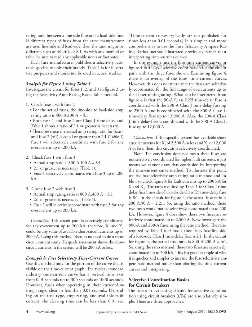
In this example, use the fuse time-current curves in figure 4 to analyze selective coordination for the circuit path with the three fuses shown. Examining figure 4, there is no overlap of the fuses’ time-current curves. However, this does not mean that the fuses are selective-ly coordinated for the full range of overcurrents up to their interrupting rating. What can be interpreted from figure 4 is that the 90-A Class RK5 time-delay fuse is coordinated with the 200-A Class J time-delay fuse up to 2500 A and is coordinated with the 800-A Class L time-delay fuse up to 12,000 A. Also, the 200-A Class J time-delay fuse is coordinated with the 800-A Class L fuse up to 12,000 A.
Conclusion: If this specific system has available short-circuit currents for X1 of 2,500 A or less and X2 of 12,000 A or less; then, this circuit is selectively coordinated.
not selectively coordinated for higher fault currents; it just means we cannot draw that conclusion by interpreting the time-current curve method. To illustrate this point, use the fuse selectivity amp rating ratio method and Ta-ble 1 to check figure 4 for fault currents up to 200 kA for X1and X2delay fuse line-side of a load-side Class K5 time-delay fuse is 8:1. In the circuit for figure 4, the actual fuse ratio is 200 A:90 A = 2.2:1. So, using the ratio method, these two fuses would not be selectively coordinated up to 200 kA. However, figure 4 does show these two fuses are se-lectively coordinated up to 2,500 A. Now investigate the
required by Table 1 for Class L time-delay fuse line-side of a load-side Class J time-delay fuse is 2:1. In the circuit for figure 4, the actual fuse ratio is 800 A:200 A = 4:1. So, using the ratio method, these two fuses are selectively
it is quicker and simpler to just use the fuse selectivity am-pere ratio method rather than plotting the time-current curves and interpreting.
Selective Coordination Basicsfor Circuit Breakers
-tion using circuit breakers (CBs) are also relatively sim-
www.iaei.org July . August 2010 IAEI NEWS
SELECTIVE COORDINATION ENFORCEMENT
Reprinted by permission of IAEI News4
SELECTIVE COORDINATION ENFORCEMENT
a. If the clearing time of all the CBs is great-er than 0.01 seconds for the line-side available short-circuit current, the CB time-current curves cannot cross.b. If the CB time-current curves cross, the available short-circuit current at the point of intersection is interpreted as the maximum short-circuit current to
an exception if CB manufacturers’ Selectivity Tables provide data verifying two specific CBs selectively coordinate to a higher short-circuit current level.c. If clearing time of the CB is less than 0.01 seconds, then data is needed from the circuit breaker manu-facturer’s table method discussed in b.
a and b.
Example a: CB Curves Do Not Cross
CB time-current curves do not cross. To achieve this “no overlap” situation, it normally requires the use of feeder and main CBs with short-time delay settings and no in-
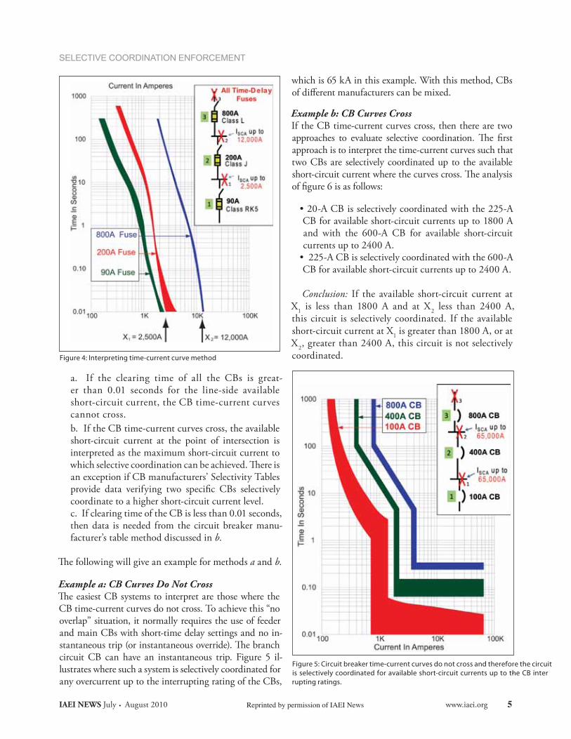
circuit CB can have an instantaneous trip. Figure 5 il-lustrates where such a system is selectively coordinated for any overcurrent up to the interrupting rating of the CBs,
which is 65 kA in this example. With this method, CBs of different manufacturers can be mixed.
Example b: CB Curves CrossIf the CB time-current curves cross, then there are two
approach is to interpret the time-current curves such that two CBs are selectively coordinated up to the available
of figure 6 is as follows:
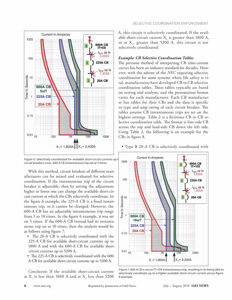
20-A CB is selectively coordinated with the 225-A CB for available short-circuit currents up to 1800 A and with the 600-A CB for available short-circuit currents up to 2400 A. 225-A CB is selectively coordinated with the 600-A CB for available short-circuit currents up to 2400 A.
Conclusion: If the available short-circuit current at X1 is less than 1800 A and at X2 less than 2400 A, this circuit is selectively coordinated. If the available short-circuit current at X1 is greater than 1800 A, or at X2, greater than 2400 A, this circuit is not selectively coordinated.Figure 4: Interpreting time-current curve method
Figure 5: Circuit breaker time-current curves do not cross and therefore the circuit is selectively coordinated for available short-circuit currents up to the CB inter-rupting ratings.
IAEI NEWS July . August 2010 www.iaei.orgReprinted by permission of IAEI News 5
SELECTIVE COORDINATION ENFORCEMENT
With this method, circuit breakers of different man-ufacturers can be mixed and evaluated for selective coordination. If the instantaneous trip of the circuit breaker is adjustable, then by setting the adjustment higher or lower one can change the available short-cir-cuit current at which the CBs selectively coordinate. In the figure 6 example, the 225-A CB is a fixed instan-taneous trip, so it cannot be changed. However, the 600-A CB has an adjustable instantaneous trip range from 5 to 10 times. In the figure 6 example, it was set on 5 times. If the 600-A CB instead had its instanta-neous trip set at 10 times, then the analysis would be as follows using figure 7:
225-A CB for available short-circuit currents up to 1800 A and with the 600-A CB for available short-circuit currents up to 5200 A.
A CB for available short-circuit currents up to 5200 A.
Conclusion: If the available short-circuit current at X1 is less than 1800 A and at X2 less than 5200
A, this circuit is selectively coordinated. If the avail-able short-circuit current X1 is greater than 1800 A, or at X2, greater than 5200 A, this circuit is not selectively coordinated.
Example: CB Selective Coordination Tables
curves has been an industry standard for decades. How-ever, with the advent of the NEC requiring selective coordination for some systems where life safety is vi-tal, manufacturers have developed CB to CB selective
on testing and analysis, and the presentation format varies for each manufacturer. Each CB manufactur-er has tables for their CBs and the data is specific
tables assume CB instantaneous trips are set on the highest settings. Table 2 is a fictitious CB to CB se-
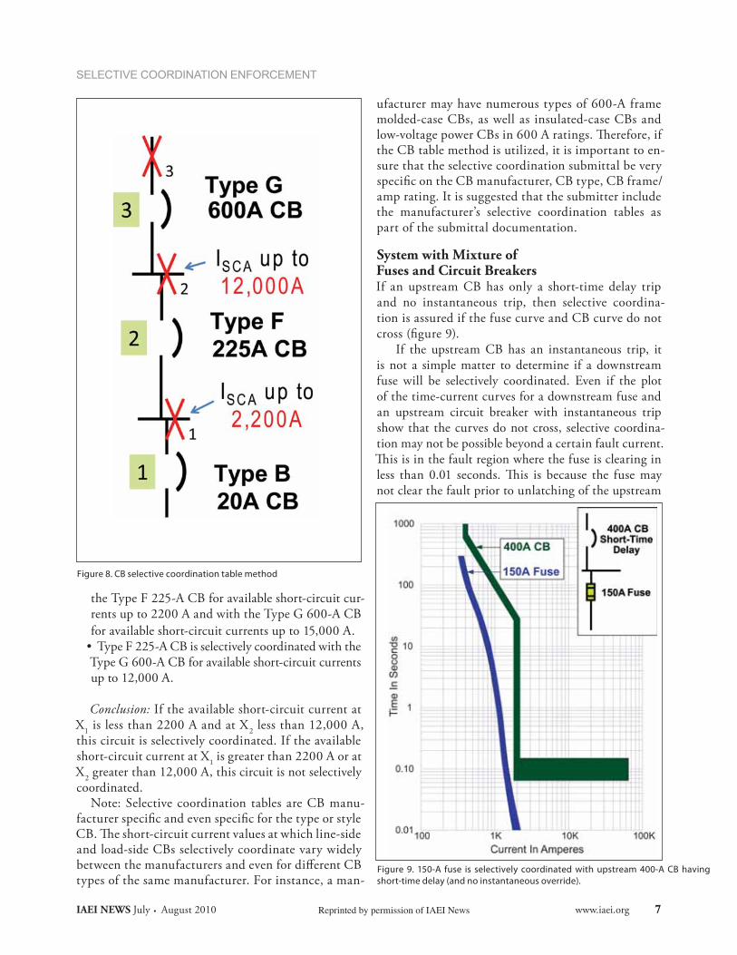
across the top and load-side CB down the left side. Using Table 2, the following is an example for the CBs in figure 8.
Type B 20-A CB is selectively coordinated with
Figure 6. Selectively coordinated for available short-circuit currents up to where circuit breakers cross. 600-A CB instantaneous trip set at 5 times.
Figure 7. 600-A CB is set on IT=10X instantaneous trip, resulting in its being able to selectively coordinate up to a higher available short-circuit current versus figure 6 example.
www.iaei.org July . August 2010 IAEI NEWS Reprinted by permission of IAEI News6
SELECTIVE COORDINATION ENFORCEMENT
the Type F 225-A CB for available short-circuit cur-rents up to 2200 A and with the Type G 600-A CB for available short-circuit currents up to 15,000 A. Type F 225-A CB is selectively coordinated with the Type G 600-A CB for available short-circuit currents up to 12,000 A.
Conclusion: If the available short-circuit current at X1 is less than 2200 A and at X2 less than 12,000 A, this circuit is selectively coordinated. If the available short-circuit current at X1 is greater than 2200 A or at X2 greater than 12,000 A, this circuit is not selectively coordinated.
Note: Selective coordination tables are CB manu-facturer specific and even specific for the type or style
and load-side CBs selectively coordinate vary widely between the manufacturers and even for different CB types of the same manufacturer. For instance, a man-
ufacturer may have numerous types of 600-A frame molded-case CBs, as well as insulated-case CBs and
the CB table method is utilized, it is important to en-sure that the selective coordination submittal be very specific on the CB manufacturer, CB type, CB frame/amp rating. It is suggested that the submitter include the manufacturer’s selective coordination tables as part of the submittal documentation.
System with Mixture ofFuses and Circuit BreakersIf an upstream CB has only a short-time delay trip and no instantaneous trip, then selective coordina-tion is assured if the fuse curve and CB curve do not cross (figure 9).
If the upstream CB has an instantaneous trip, it is not a simple matter to determine if a downstream fuse will be selectively coordinated. Even if the plot of the time-current curves for a downstream fuse and an upstream circuit breaker with instantaneous trip show that the curves do not cross, selective coordina-tion may not be possible beyond a certain fault current.
not clear the fault prior to unlatching of the upstream
Figure 8. CB selective coordination table method
Figure 9. 150-A fuse is selectively coordinated with upstream 400-A CB having short-time delay (and no instantaneous override).
IAEI NEWS July . August 2010 www.iaei.orgReprinted by permission of IAEI News 7
SELECTIVE COORDINATION ENFORCEMENT
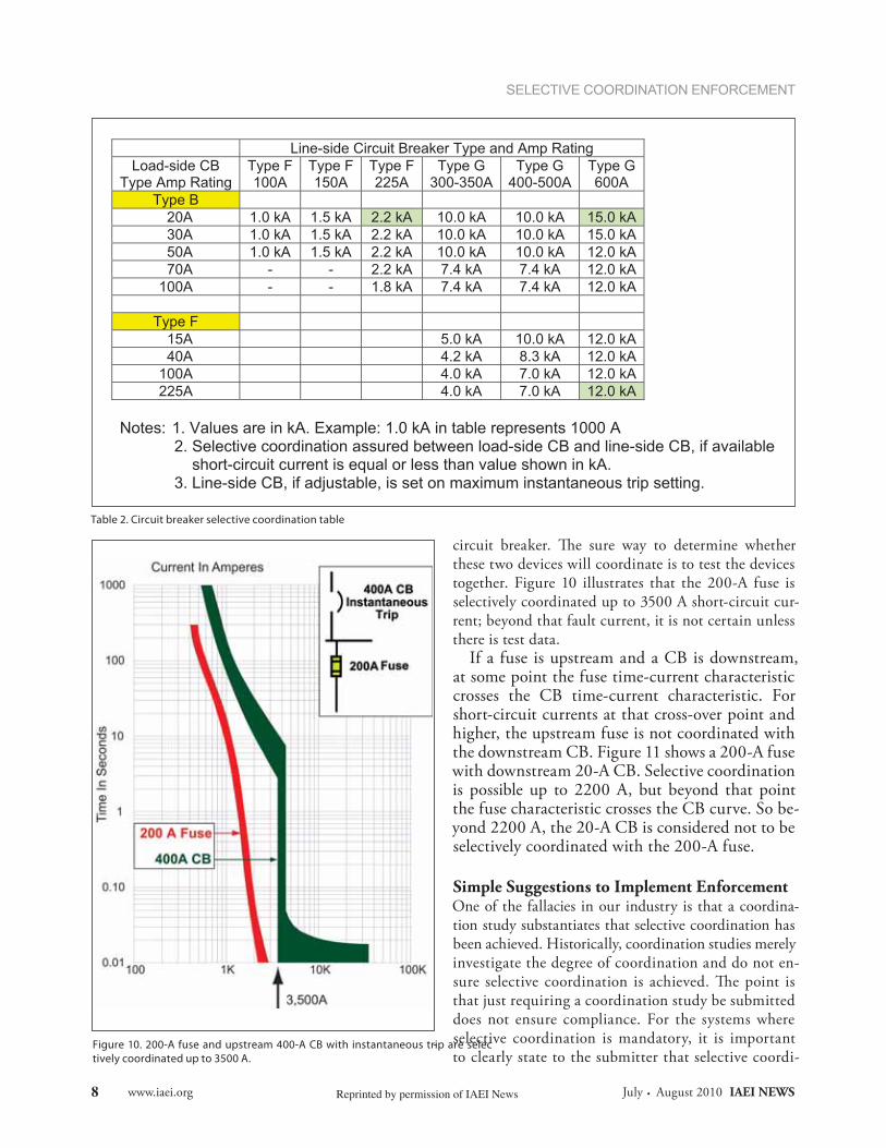
these two devices will coordinate is to test the devices together. Figure 10 illustrates that the 200-A fuse is selectively coordinated up to 3500 A short-circuit cur-rent; beyond that fault current, it is not certain unless there is test data.
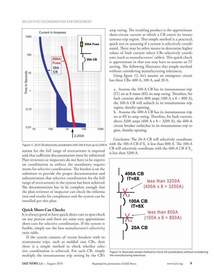
If a fuse is upstream and a CB is downstream, at some point the fuse time-current characteristic crosses the CB time-current characteristic. For short-circuit currents at that cross-over point and higher, the upstream fuse is not coordinated with the downstream CB. Figure 11 shows a 200-A fuse with downstream 20-A CB. Selective coordination is possible up to 2200 A, but beyond that point the fuse characteristic crosses the CB curve. So be-yond 2200 A, the 20-A CB is considered not to be selectively coordinated with the 200-A fuse.
Simple Suggestions to Implement EnforcementOne of the fallacies in our industry is that a coordina-tion study substantiates that selective coordination has been achieved. Historically, coordination studies merely investigate the degree of coordination and do not en-
that just requiring a coordination study be submitted does not ensure compliance. For the systems where selective coordination is mandatory, it is important to clearly state to the submitter that selective coordi-
Table 2. Circuit breaker selective coordination table
Line-side Circuit Breaker Type and Amp Rating Load-side CB
Type Amp Rating Type F 100A
Type F 150A
Type F225A
Type G 300-350A
Type G 400-500A
Type G 600A
Type B 20A 1.0 kA 1.5 kA 2.2 kA 10.0 kA 10.0 kA 15.0 kA 30A 1.0 kA 1.5 kA 2.2 kA 10.0 kA 10.0 kA 15.0 kA 50A 1.0 kA 1.5 kA 2.2 kA 10.0 kA 10.0 kA 12.0 kA 70A - - 2.2 kA 7.4 kA 7.4 kA 12.0 kA100A - - 1.8 kA 7.4 kA 7.4 kA 12.0 kA
Type F 15A 5.0 kA 10.0 kA 12.0 kA 40A 4.2 kA 8.3 kA 12.0 kA100A 4.0 kA 7.0 kA 12.0 kA225A 4.0 kA 7.0 kA 12.0 kA
Notes: 1. Values are in kA. Example: 1.0 kA in table represents 1000 A
2. Selective coordination assured between load-side CB and line-side CB, if available short-circuit current is equal or less than value shown in kA. 3. Line-side CB, if adjustable, is set on maximum instantaneous trip setting.
Figure 10. 200-A fuse and upstream 400-A CB with instantaneous trip are selec-tively coordinated up to 3500 A.
www.iaei.org July . August 2010 IAEI NEWS Reprinted by permission of IAEI News8
SELECTIVE COORDINATION ENFORCEMENT
Figure 11. 20-A CB selectively coordinates with 200-A fuse up to 2200 A.
nation for the full range of overcurrents is required and that sufficient documentation must be submitted. Plan reviewers or inspectors do not have to be experts on coordination to enforce the mandatory require-
submitter to provide the proper documentation and substantiation that selective coordination for the full range of overcurrents in the system has been achieved.
the plan reviewer or inspector can check the informa-tion and results for compliance and the system can be installed per this plan.
Quick Short-Cut ChecksIt is always good to have quick short-cuts to spot check on any process and there are some easy approximate short-cuts for selective coordination. If the system is fusible, simply use the fuse manufacturer’s selectivity ratio table.
If the system consists of circuit breakers with in-stantaneous trips, such as molded case CBs, then there is a simple method to check whether selec-tive coordination is achieved. For each CB, simply multiply the instantaneous trip setting by the CB’s
short-circuit current at which a CB enters its instan-
quick test in assessing if a system is selectively coordi-
values of fault current where CBs selectively coordi-
is approximate in that you may have to assume an IT
without considering manufacturing tolerances.Using figure 12, let’s assume an emergency circuit
has three CBs: 400 A, 100 A, and 20 A.
a. Assume the 100-A CB has its instantaneous trip
fault currents above 800 amps (100 A x 8 = 800 A), the 100-A CB will unlatch in its instantaneous trip region, thereby opening. b. Assume the 400-A CB has its instantaneous trip
above 3200 amps (400 A x 8 = 3200 A), the 400-A circuit breaker unlatches in its instantaneous trip re-gion, thereby opening.
Conclusion: with the 100-A CB if X1CB will selectively coordinate with the 400-A CB if X2 is less than 3200 A.
Figure 12. Illustrates simple method to check CB coordination without considering the manufacturing tolerances
IAEI NEWS July . August 2010 www.iaei.orgReprinted by permission of IAEI News 9
SELECTIVE COORDINATION ENFORCEMENT
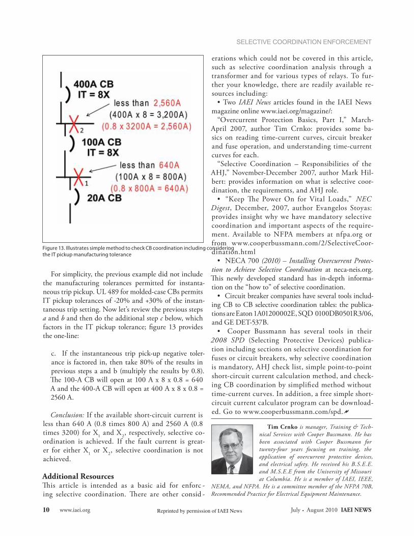
For simplicity, the previous example did not include the manufacturing tolerances permitted for instanta-neous trip pickup. UL 489 for molded-case CBs permits IT pickup tolerances of -20% and +30% of the instan-taneous trip setting. Now let’s review the previous steps a and b and then do the additional step c below, which factors in the IT pickup tolerance; figure 13 provides the one-line:
c. If the instantaneous trip pick-up negative toler-ance is factored in, then take 80% of the results in previous steps a and b (multiply the results by 0.8).
A and the 400-A CB will open at 400 A x 8 x 0.8 = 2560 A.
Conclusion: If the available short-circuit current is less than 640 A (0.8 times 800 A) and 2560 A (0.8 times 3200) for X1 and X2, respectively, selective co-ordination is achieved. If the fault current is great-er for either X1 or X2, selective coordination is not achieved.
Additional ResourcesThis article is intended as a basic aid for enforc -ing selective coordination. There are other consid -
erations which could not be covered in this article, such as selective coordination analysis through a transformer and for various types of relays. To fur-ther your knowledge, there are readily available re-sources including:
Two IAEI News articles found in the IAEI News magazine online www.iaei.org/magazine/:
“Overcurrent Protection Basics, Part I,” March-April 2007, author Tim Crnko: provides some ba-sics on reading time-current curves, circuit breaker and fuse operation, and understanding time-current curves for each.
“Selective Coordination – Responsibilities of the AHJ,” November-December 2007, author Mark Hil-bert: provides information on what is selective coor-dination, the requirements, and AHJ role.
“Keep The Power On for Vital Loads,” NEC Digest, December, 2007, author Evangelos Stoyas: provides insight why we have mandatory selective coordination and important aspects of the require-ment. Available to NFPA members at nfpa.org or from www.cooperbussmann.com/2/SelectiveCoor-dination.html
NECA 700 (2010) – Installing Overcurrent Protec-tion to Achieve Selective Coordination at neca-neis.org.
-tion on the “how to” of selective coordination.
Circuit breaker companies have several tools includ-ing CB to CB selective coordination tables: the publica-tions are Eaton 1A01200002E, SQD 0100DB0501R3/06, and GE DET-537B.
Cooper Bussmann has several tools in their 2008 SPD (Selecting Protective Devices) publica-tion including sections on selective coordination for fuses or circuit breakers, why selective coordination is mandatory, AHJ check list, simple point-to-point short-circuit current calculation method, and check-ing CB coordination by simplified method without time-current curves. In addition, a free simple short-circuit current calculator program can be download-ed. Go to www.cooperbussmann.com/spd.
Tim Crnko is manager, Training & Tech-nical Services with Cooper Bussmann. He has been associated with Cooper Bussmann for twenty-four years focusing on training, the application of overcurrent protective devices, and electrical safety. He received his B.S.E.E. and M.S.E.E from the University of Missouri at Columbia. He is a member of IAEI, IEEE,
NEMA, and NFPA. He is a committee member of the NFPA 70B, Recommended Practice for Electrical Equipment Maintenance.
Figure 13. Illustrates simple method to check CB coordination including considering the IT pickup manufacturing tolerance
www.iaei.org July . August 2010 IAEI NEWS Reprinted by permission of IAEI News10