Embed Size (px)
Citation preview
409
Chapter 9
Seismic Design of Steel Structures
Chia-Ming Uang, Ph.D.Professor of Structural Engineering, University of California, San Diego
Michel Bruneau, Ph.D., P.Eng.Professor of Civil Engineering, State University of New York at Buffalo
Andrew S. Whittaker, Ph.D., S.E.Associate Professor of Civil Engineering, State University of New York at Buffalo
Key-Chyuan Tsai, Ph.D., S.E.Professor of Civil Engineering, National Taiwan University
Key words: Seismic Design, Steel Structures, NEHRP Recommended Seismic Provisions, AISC Seismic Provisions, RFactor, Ductility, System Overstrength, Capacity Design, 1994 Northridge Earthquake, Moment-ResistingFrames, Brittle Fracture, Moment Connections, Concentrically Braced Frames, Buckling, Braces,Eccentrically Braced Frames, Links.
Abstract: Seismic design of steel building structures has undergone significant changes since the Northridge,California earthquake in 1994. Steel structures, thought to be ductile for earthquake resistance, experiencedbrittle fracture in welded moment connections. The latest AISC Seismic Provisions reflect the significantresearch findings that resulted from the Northridge earthquake. This chapter first starts with a description ofthe seismic design philosophy, the concept of system parameters (R, Cd, and Ωo) and capacity design.Background information for the seismic requirements in the AISC Seismic Provisions of Moment Frames,Concentrically Braced Frames, and Eccentrically Braced Frames are then presented. Design examples areprovided for each of the three structural systems.

410 Chapter 9

9. Seismic Design of Steel Structures 411
9.1 Introduction
9.1.1 General
Steel is one of the most widely usedmaterials for building construction in NorthAmerica. The inherent strength and toughnessof steel are characteristics that are well suited toa variety of applications, and its high ductility isideal for seismic design. To utilize theseadvantages for seismic applications, the designengineer has to be familiar with the relevantsteel design provisions and their intent and mustensure that the construction is properlyexecuted. This is especially important whenwelding is involved.
The seismic design of building structurespresented in this chapter is based on theNEHRP Recommended Provisions for theDevelopment of Seismic Regulation for NewBuildings (BSSC 1997). For seismic steeldesign, the NEHRP Recommended Provisionsincorporate by reference the AISC SeismicProvisions for Structural Steel Buildings(1997b).
9.1.2 NEHRP Seismic Design Concept
The NEHRP Recommended Provisions arebased on the R-factor design procedure. In thisprocedure, certain structural components aredesignated as the structural fuses and arespecially detailed to respond in the inelasticrange to dissipate energy during a majorearthquake. Since these components areexpected to experience significant damage,their locations are often selected such that thedamage of these components would not impairthe gravity load-carrying capacity of thesystem. Aside from these energy dissipatingcomponents, all other structural componentsincluding connections are then proportionedfollowing the capacity design concept to remainin the elastic range.
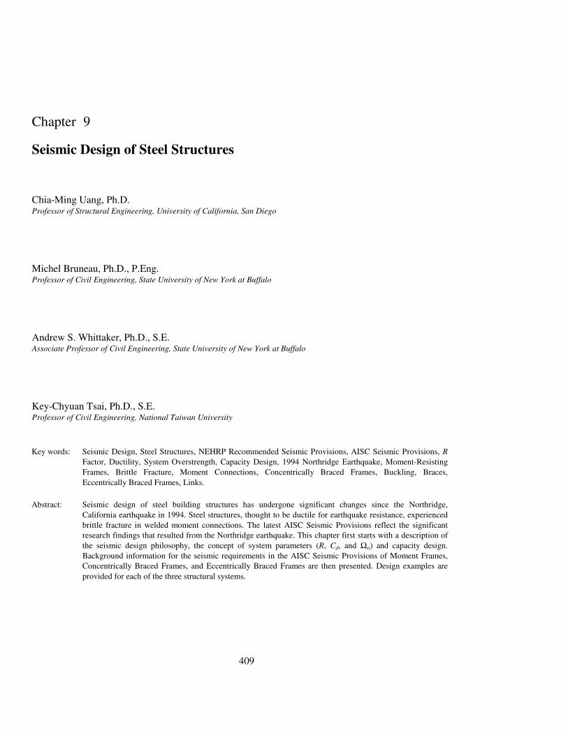
Consider a structural response envelopeshown in Figure 9-1, where the abscissa andordinate represent the story drift and base shear
ratio, respectively. If the structure is designed torespond elastically during a major earthquake,the required elastic base shear ratio, Ceu, wouldbe high. For economical reasons, the NEHRPRecommended Provisions take advantage of thestructure's inherent energy dissipation capacityby specifying a design seismic force level, Cs,which is reduced significantly from Ceu by aresponse modification factor, R:
R
CC eu
s = (9-1)
The Cs design force level is the firstsignificant yield level of the structure, whichcorresponds to the force level beyond which thestructural response starts to deviate significantlyfrom the elastic response. Idealizing the actualresponse envelope by a linearly elastic-perfectlyplastic response shown in Figure 9-1, it can beshown that the R factor is composed of twocontributing factors (Uang 1991):
oΩ= µRR (9-2)
The ductility reduction factor, Rµ, accountsfor the reduction of seismic forces from Ceu toCy, Such a force reduction is possible becauseductility, which is measured by the ductilityfactor µ (= δs/δy), is provided by the energy-dissipating components in the structural system.
The system overstrength factor, Ωo, in Eq.9-2 accounts for the reserve strength betweenthe force levels Cy and Cs. Several factorscontribute to this overstrength factor. Theseinclude structural redundancy, story drift limits,material overstrength, member oversize, non-seismic load combinations, and so on.
The R-factor design approach greatlysimplifies the design process because the designengineer only has to perform an elasticstructural analysis even though the structure isexpected to deform well into the inelastic rangeduring a major earthquake. After the elasticstory drift, δe, is computed from a structuralanalysis, the NEHRP Recommended Provisionsthen specify a deflection amplification factor,
412 Chapter 9
Cd, to estimate the Design Story Drift, δs, inFigure 9-1:
I
C eds
δ=δ (9-3)
where I is the Occupancy Importance Factor.The story drift thus computed cannot exceed theallowable drift specified in the NEHRPRecommended Provisions. Depending on theSeismic Use Group, the allowable drift for steelbuildings varies from 1.5% to 2.5% of the storyheight.
Note that the ultimate strength of thestructure (Cy in Figure 9-1) is not known if onlyan elastic analysis is performed at the Cs designforce level. Nevertheless, the ultimate strengthof the structure is required in capacity design toestimate, for example, the axial force in thecolumns when a yield mechanism forms in thestructure. For this purpose, the NEHRPRecommended Provisions specify Ωo values tosimplify the design process. Therefore, inaddition to the load combinations prescribed in
the AISC LRFD Specification (1993), the AISCSeismic Provisions require that the columns bechecked for two additional special loadcombinations using the amplified horizontalearthquake load effects, ΩoE:
ESLD o2.05.02.1 Ω+++ (9-4)
ED o9.0 Ω− (9-5)
The amplified seismic load effects are to beapplied without consideration of any concurrentbending moment on the columns. In addition,the required strengths determined from thesetwo load combinations need not exceed either(1) the maximum load transferred to the columnconsidering 1.1Ry times the nominal strengthsof the connecting beam or brace elements of theframe, or (2) the limit as determined by theresistance of the foundation to uplift. Refer tothe next section for the factor Ry.
The R, Cd, and Ωo values specified in theNEHRP Recommended Provisions for differenttypes of steel framing systems are listed in
Figure 9-1. General structural response envelope
9. Seismic Design of Steel Structures 413
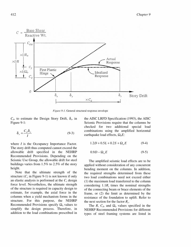
Table 9-1. Seismic design of three widely usedsystems (moment-resisting frames,concentrically braced frames, and eccentricallybraced frames) that are presented later in thischapter makes use of these parameters.
9.1.3 Structural Steel Materials
The ductility of steel generally reduces withan increase of the yield stress. Therefore, theAISC Seismic Provisions permit only thefollowing grades of steel for seismic design:ASTM A36, A53, A500 (Grades B and C),A501, A572 (Grades 42 or 50), A588, A913(Grade 50 or 65), or A992. Further, for thosestructural members that are designed to yieldunder load combinations involving Ωo times thedesign seismic forces, the specified minimumyield strength, Fy, shall not exceed 50 ksi unlessthe suitability of the material is determined bytesting or other rational criteria. This limitationdoes not apply to columns of A588 or A913
Grade 65 steel for which the only expectedinelastic behavior is yielding at the columnbase.
The specified minimum yield strength isused to design the structural components thatare expected to yield during the designearthquake. However, to estimate the forcedemand these components would impose onother structural components (includingconnections) that are expected to remain elastic,the expected yield strength, Fye, of the energydissipating components needs to be used forcapacity design:
yyye FRF = (9-6)
For rolled shapes and bars, the AISC SeismicProvisions stipulate that Ry shall be taken as 1.5for A36 and 1.3 for A572 Grade 42. For rolledshapes and bars of other grades of steel and forplates, Ry shall be taken as 1.1 (SSPC 1995).
Table 9-1. Steel framing systems and design parameters (NEHRP 1997)Frame System R Ωo Cd
Bearing Wall Systems Ordinary Concentrically Braced Frames (OCBFs) 4 2 3 ½Building Frame Systems Eccentrically Braced Frames (EBFs) • Moment connections at columns away from links 8 2 4 • Non-moment connections at columns away from links 7 2 4 Special Concentrically Braced Frames (SCBFs) 6 2 5 Ordinary Concentrically Braced Frames(OCBFs) 5 2 4 ½Moment Resisting Frame Systems Special Moment Frames (SMFs) 8 3 5 ½ Intermediate Moment Frames (IMFs) 6 3 5 Ordinary Moment Frames (OMFs) 4 3 3 ½ Special Truss Moment Frames (STMFs) 7 3 5 ½Dual Systems with SMFs Capable of Resisting at Least 25% of Prescribed SeismicForces Eccentrically Braced Frames (EBFs) • Moment connections at columns away from links 8 2 ½ 4 • Non-moment connections at columns away from links 7 2 ½ 4 Special Concentrically Braced frames (SCBFs) 8 2 ½ 6 ½ Ordinary Concentrically Braced Frames (OCBFs) 6 2 ½ 5
414 Chapter 9
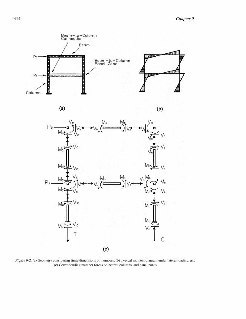
Figure 9-2. (a) Geometry considering finite dimensions of members, (b) Typical moment diagram under lateral loading, and(c) Corresponding member forces on beams, columns, and panel zones
9. Seismic Design of Steel Structures 415
9.2 Behavior and Design ofMoment-Resisting Frames
9.2.1 Introduction
Steel moment-resisting frames (SMFs) arerectilinear assemblies of columns and beamsthat are typically joined by welding or high-strength bolting or both. Resistance to lateralloads is provided by flexural and shearingactions in the beams and the columns. Lateralstiffness is provided by the flexural stiffness ofthe beams and columns; the flexibility of thebeam-column connections are often ignoredalthough such flexibility may substantiallyincrease deflections in a moment-resistingframe. Components of an SMF together withsample internal actions are shown in Figure. 9-2.
The AISC Seismic Provisions define threetypes of seismic steel moment-resisting frames:Ordinary Moment Frames, IntermediateMoment Frames, and Special Moment Frames.All three framing systems are designedassuming ductile behavior of varying degrees,for earthquake forces that are reduced from theelastic forces by a response modification factor,R (see Table 9-1 for values of R).
SMFs are considered to be the most ductileof the three types of moment frames consideredby AISC. For this reason, and due to theirarchitectural versatility, SMFs have been themost popular seismic framing system in highseismic regions in the United States. SMFs aredesigned for earthquake loads calculated usinga value of R equal to 8. Stringent requirementsare placed on the design of beams, columns,beam-to-column connections, and panel zones.Beam-to-column connections in SMFs arerequired to have a minimum inelastic rotationcapacity of 0.03 radian.
Intermediate Moment Frames (IMFs) areassumed to be less ductile than SMFs but areexpected to withstand moderate inelasticdeformations in the design earthquake. IMFsare designed using a value of R equal to 6; fullyrestrained (FR) or partially restrained (PR)
connections can be used in such frames. Beam-to-column connections in IMFs are required tohave an inelastic rotation capacity of 0.02radian. Other requirements are listed in theAISC Seismic Provisions (1997b).
Ordinary moment frames (OMFs) are lessductile than IMFs, and are expected to sustainonly limited inelastic deformations in theircomponents and connections in the designearthquake. Beam-to-column connections inOMFs are required to have an inelastic rotationcapacity of 0.01 radian. FR and PR connectionscan be used in OMFs. Because OMFs are lessductile than IMFs, an OMF must be designedfor higher seismic forces than an IMF; an OMFis designed for earthquake loads calculatedusing a value of R equal to 4.
The remainder of this section addressesissues associated with the design, detailing, andtesting of special moment frames andcomponents. The design philosophy for suchframes is to dissipate earthquake-inducedenergy in plastic hinging zones that typicallyform in the beams and panel zones of the frame.Columns and beam-to-column connections aretypically designed to remain elastic usingcapacity design procedures.
9.2.2 Analysis and Detailing of SpecialMoment Frames
Because the SMF is a flexible framingsystem, beam and column sizes in SMFs areoften selected to satisfy story driftrequirements. As such, the nominal structuralstrength of an SMF can substantially exceed theminimum base shear force required by theNEHRP Recommended Provisions. Whenanalyzing SMFs, all sources of deformationshould be considered in the mathematicalmodel. NEHRP stipulates that panel zonedeformations must be included in thecalculation of story drift.
The AISC Seismic Provisions prescribegeneral requirements for materials andconnections that are particularly relevant toSMF construction:
416 Chapter 9
1. Steel in SMF construction must complywith the requirements described inSection 9.1.3. In addition, a minimumCharpy V-notch toughness of 20 ft-lbs at70°F is required for thick materials inSMFs: ASTM A6 Group 3 shapes withflanges 1½ inches or thicker, ASTM A6Groups 4 and 5 shapes, and plates thatare 1½ inches or greater in thickness inbuilt-up members.
2. Calculation of maximum componentstrengths (e.g., for strong column-weakbeam calculations) for capacity designmust be based on the expected yieldstrength, yeF (see Eq. 9-6).
3. To prevent brittle fractures at the welds,AISC prescribes that welded joints beperformed in accordance with anapproved Welding ProcedureSpecifications and that all welds used inprimary members and connections in theseismic force resisting system be madewith a filler metal that has a minimumCharpy V-notch toughness of 20 ft-lbs atminus 20°F.
9.2.3 Beam Design
A beam in a steel SMF is assumed to be ableto develop its full plastic moment (Mp)calculated as
ybp FZM = (9-7)
where bZ is the plastic section modulus. Inorder to prevent premature beam flange or weblocal buckling, and to maintain this moment forlarge plastic deformations, the width-thicknessratios of the web and flange elements should belimited to the values of psλ given in Table 9-2.
(The pλ values are for non-seismic design.) In
addition, both flanges of the beam must belaterally braced near potential plastic hinges;the unbraced length of the beam must notexceed 2500 yr /Fy, where ry is the radius of
gyration about the weak axis for out-of-planebuckling.
9.2.4 Beam-to-Column Connections
Introduction
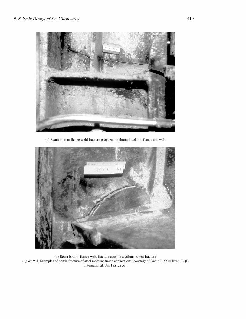
For discussion purposes, a beam-to-columnconnection includes the beam-column panelzone and the beam-to-column joints.Connections in an SMF need to satisfy threecriteria: (1) a sufficient strength to develop thefull plastic moment of the beam, (2) a sufficientstiffness to satisfy the assumption of a fullyrigid (FR) connection, and (3) a large post-yielddeformation capacity without significant loss ofstrength. Prior to the 1994 Northridge,California earthquake, the welded flange-boltedweb steel moment connections were assumedby design professionals to easily satisfy allthree criteria. Unfortunately, many moment-resisting connections suffered extensivedamage during this earthquake. In addition tobrittle fracture in the groove weldedconnections (mostly in the beam bottomflange), other types of fracture that were seldomobserved in laboratory testing prior to theNorthridge earthquake were also reported.Figure 9-3a shows cracks extending into thecolumn panel zone, and Figure 9-3b presents a“divot” pullout from the column flange. Thecauses of failure are discussed in Bruneau et al.(1997).
The poor performance of welded moment-frame connections in more than 200 multistorybuildings in the Northridge earthquake led tothe development of a national program, fundedby the Federal Emergency ManagementAgency (FEMA), to investigate the causes offailure and to develop alternative connectionsfor repair, rehabilitation, and new construction.Part of the FEMA program involved full-scaletesting of large-size steel beam-columnconnections (SAC 1996). The laboratory testingof the pre-Northridge prequalified weldedflange-bolted web connection replicated manyof the failure modes observed in the field afterthe earthquake. The mean value of beam plastic
9. Seismic Design of Steel Structures 417
rotation capacity from all of the tests of the pre-Northridge connection detail was 0.004 radian(Whittaker et al. 1998), which was significantlyless than the target value of 0.03 radian. Inresponse to these findings, the 1997 AISCSeismic Provisions require that (1) the design ofbeam-to-column joints and connections inSMFs must be based on qualifying tests of atleast two specimens, and (2) each connectionmust develop a plastic rotation of 0.03 radian.
Beam-to-Column Connection Details
Shortly after the 1994 earthquake, theprequalified welded flange-bolted webconnection was deleted from most buildingcodes and replaced by general provisions thatrequired the design professional to demonstratethe adequacy of the connection by either full-scale testing or calculations supported by testdata. In response to this action, designprofessionals have proposed new types ofmoment-resisting connections for steelbuildings. Some of these proposals arediscussed below. In all cases, the proposedconnection details relocate the beam plastichinge away from the face of the column. Only
welded connections are considered in thissection.
These connection details fall in one of thetwo categories: weakening the beam cross-section away from the face of the column, orreinforcing the beam cross-section at thecolumn face. Only non-proprietary momentconnections are discussed.
Reinforced Connections
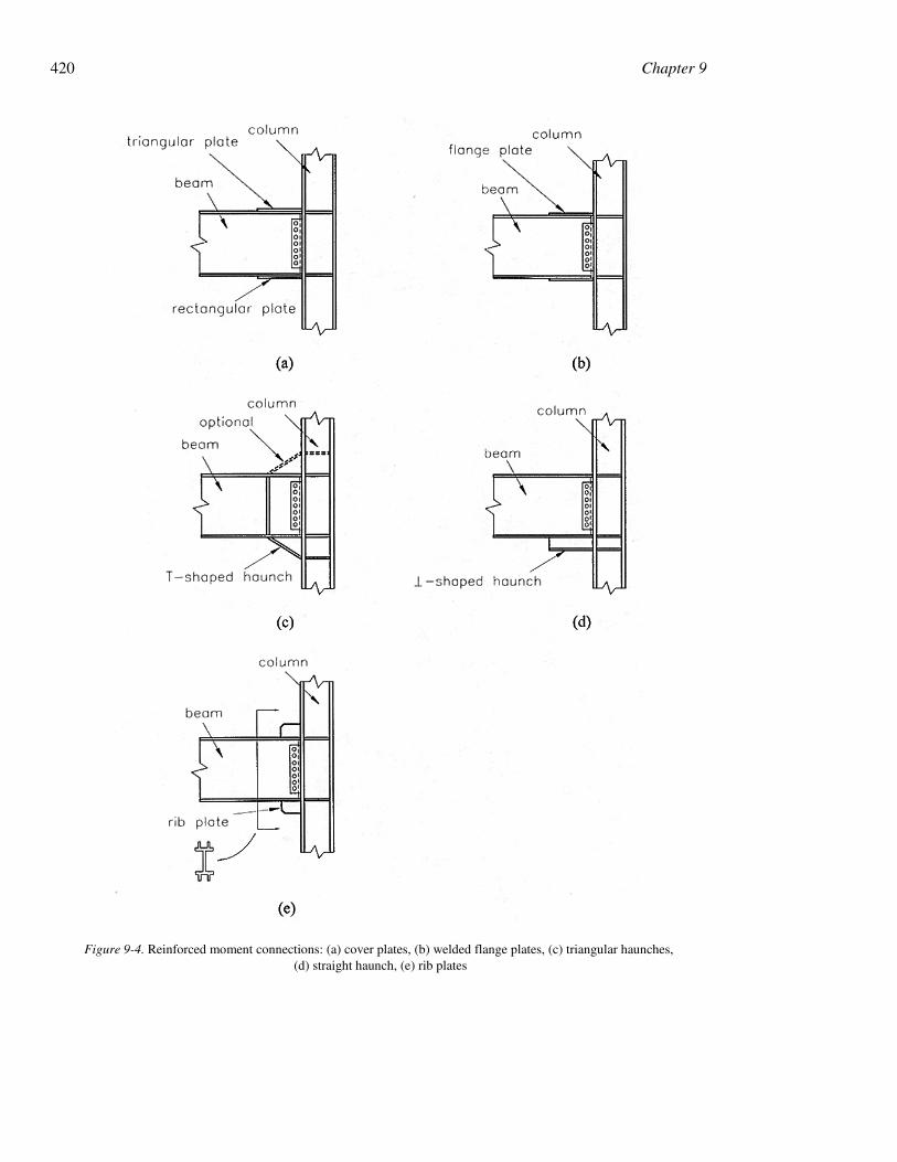
A variety of reinforced connections havebeen developed since the Northridgeearthquake. Some reinforced connection detailsare shown in Figure. 9-4: cover plates, weldedflange plates, triangular haunches, straighthaunches, and vertical plate ribs. Note thatthese connection details would not onlyincrease the beam plastic hinge rotation demandbut also increase the maximum momentdemand at the face of the column, which couldrequire a stronger panel zone or a larger sectionfor the column to maintain the strong column-weak beam system (SAC 1995). Typical designpractice for reinforced connections is to keepthe reinforced component in the elastic rangefor moments associated with substantial strain
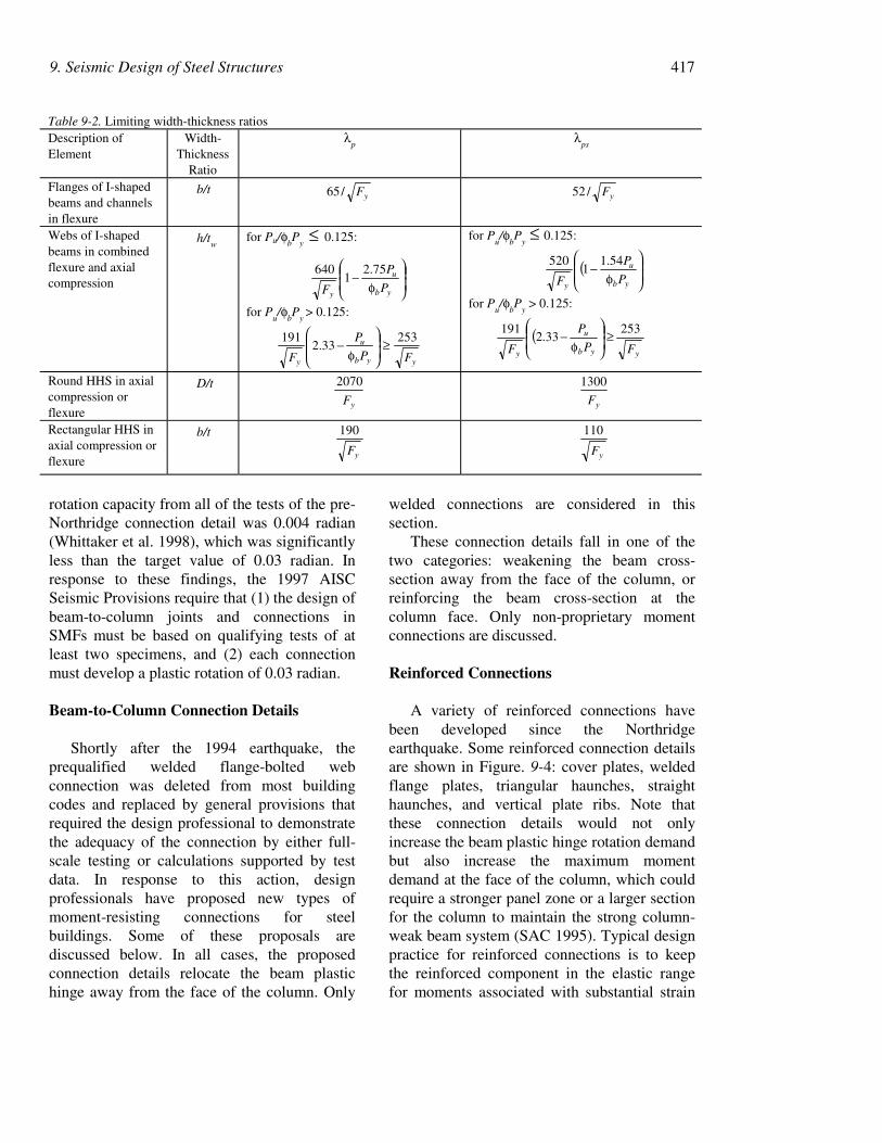
Table 9-2. Limiting width-thickness ratiosDescription ofElement
Width-Thickness
Ratio
λp
λps
Flanges of I-shapedbeams and channelsin flexure
b/tyF/65 yF/52
Webs of I-shapedbeams in combinedflexure and axialcompression
h/tw
for Pu/φbP
y ≤ 0.125:
φ−
yb
u
yP
P
F
75.21
640
for Pu/φ
bP
y > 0.125:
yyb
u
y FP
P
F
25333.2
191 ≥
φ−
for Pu/φ
bP
y ≤ 0.125:
(
φ−
yb
u
yP
P
F
54.11
520
for Pu/φ
bP
y > 0.125:
(yyb
u
y FP
P
F
25333.2
191 ≥
φ−
Round HHS in axialcompression orflexure
D/t
yF
2070
yF
1300
Rectangular HHS inaxial compression orflexure
b/t
yF
190
yF
110
418 Chapter 9
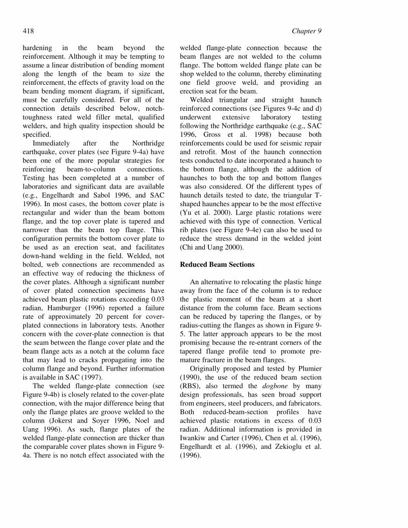
hardening in the beam beyond thereinforcement. Although it may be tempting toassume a linear distribution of bending momentalong the length of the beam to size thereinforcement, the effects of gravity load on thebeam bending moment diagram, if significant,must be carefully considered. For all of theconnection details described below, notch-toughness rated weld filler metal, qualifiedwelders, and high quality inspection should bespecified.
Immediately after the Northridgeearthquake, cover plates (see Figure 9-4a) havebeen one of the more popular strategies forreinforcing beam-to-column connections.Testing has been completed at a number oflaboratories and significant data are available(e.g., Engelhardt and Sabol 1996, and SAC1996). In most cases, the bottom cover plate isrectangular and wider than the beam bottomflange, and the top cover plate is tapered andnarrower than the beam top flange. Thisconfiguration permits the bottom cover plate tobe used as an erection seat, and facilitatesdown-hand welding in the field. Welded, notbolted, web connections are recommended asan effective way of reducing the thickness ofthe cover plates. Although a significant numberof cover plated connection specimens haveachieved beam plastic rotations exceeding 0.03radian, Hamburger (1996) reported a failurerate of approximately 20 percent for cover-plated connections in laboratory tests. Anotherconcern with the cover-plate connection is thatthe seam between the flange cover plate and thebeam flange acts as a notch at the column facethat may lead to cracks propagating into thecolumn flange and beyond. Further informationis available in SAC (1997).
The welded flange-plate connection (seeFigure 9-4b) is closely related to the cover-plateconnection, with the major difference being thatonly the flange plates are groove welded to thecolumn (Jokerst and Soyer 1996, Noel andUang 1996). As such, flange plates of thewelded flange-plate connection are thicker thanthe comparable cover plates shown in Figure 9-4a. There is no notch effect associated with the
welded flange-plate connection because thebeam flanges are not welded to the columnflange. The bottom welded flange plate can beshop welded to the column, thereby eliminatingone field groove weld, and providing anerection seat for the beam.
Welded triangular and straight haunchreinforced connections (see Figures 9-4c and d)underwent extensive laboratory testingfollowing the Northridge earthquake (e.g., SAC1996, Gross et al. 1998) because bothreinforcements could be used for seismic repairand retrofit. Most of the haunch connectiontests conducted to date incorporated a haunch tothe bottom flange, although the addition ofhaunches to both the top and bottom flangeswas also considered. Of the different types ofhaunch details tested to date, the triangular T-shaped haunches appear to be the most effective(Yu et al. 2000). Large plastic rotations wereachieved with this type of connection. Verticalrib plates (see Figure 9-4e) can also be used toreduce the stress demand in the welded joint(Chi and Uang 2000).
Reduced Beam Sections
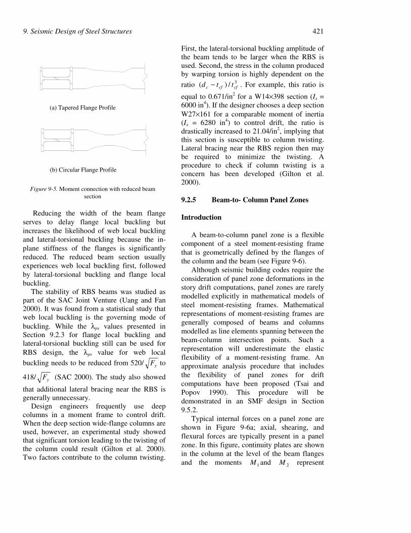
An alternative to relocating the plastic hingeaway from the face of the column is to reducethe plastic moment of the beam at a shortdistance from the column face. Beam sectionscan be reduced by tapering the flanges, or byradius-cutting the flanges as shown in Figure 9-5. The latter approach appears to be the mostpromising because the re-entrant corners of thetapered flange profile tend to promote pre-mature fracture in the beam flanges.
Originally proposed and tested by Plumier(1990), the use of the reduced beam section(RBS), also termed the dogbone by manydesign professionals, has seen broad supportfrom engineers, steel producers, and fabricators.Both reduced-beam-section profiles haveachieved plastic rotations in excess of 0.03radian. Additional information is provided inIwankiw and Carter (1996), Chen et al. (1996),Engelhardt et al. (1996), and Zekioglu et al.(1996).
9. Seismic Design of Steel Structures 419
(a) Beam bottom flange weld fracture propagating through column flange and web
(b) Beam bottom flange weld fracture causing a column divot fractureFigure 9-3. Examples of brittle fracture of steel moment frame connections (courtesy of David P. O’sullivan, EQE
International, San Francisco)
420 Chapter 9
Figure 9-4. Reinforced moment connections: (a) cover plates, (b) welded flange plates, (c) triangular haunches, (d) straight haunch, (e) rib plates
9. Seismic Design of Steel Structures 421
(a) Tapered Flange Profile
(b) Circular Flange Profile
Figure 9-5. Moment connection with reduced beamsection
Reducing the width of the beam flangeserves to delay flange local buckling butincreases the likelihood of web local bucklingand lateral-torsional buckling because the in-plane stiffness of the flanges is significantlyreduced. The reduced beam section usuallyexperiences web local buckling first, followedby lateral-torsional buckling and flange localbuckling.
The stability of RBS beams was studied aspart of the SAC Joint Venture (Uang and Fan2000). It was found from a statistical study thatweb local buckling is the governing mode ofbuckling. While the λps values presented inSection 9.2.3 for flange local buckling andlateral-torsional buckling still can be used forRBS design, the λps value for web local
buckling needs to be reduced from 520/ yF to
418/ yF (SAC 2000). The study also showed
that additional lateral bracing near the RBS isgenerally unnecessary.
Design engineers frequently use deepcolumns in a moment frame to control drift.When the deep section wide-flange columns areused, however, an experimental study showedthat significant torsion leading to the twisting ofthe column could result (Gilton et al. 2000).Two factors contribute to the column twisting.
First, the lateral-torsional buckling amplitude ofthe beam tends to be larger when the RBS isused. Second, the stress in the column producedby warping torsion is highly dependent on the
ratio 3/)( cfcfc ttd − . For example, this ratio is
equal to 0.671/in2 for a W14×398 section (Ix =6000 in4). If the designer chooses a deep sectionW27×161 for a comparable moment of inertia(Ix = 6280 in4) to control drift, the ratio isdrastically increased to 21.04/in2, implying thatthis section is susceptible to column twisting.Lateral bracing near the RBS region then maybe required to minimize the twisting. Aprocedure to check if column twisting is aconcern has been developed (Gilton et al.2000).
9.2.5 Beam-to- Column Panel Zones
Introduction
A beam-to-column panel zone is a flexiblecomponent of a steel moment-resisting framethat is geometrically defined by the flanges ofthe column and the beam (see Figure 9-6).
Although seismic building codes require theconsideration of panel zone deformations in thestory drift computations, panel zones are rarelymodelled explicitly in mathematical models ofsteel moment-resisting frames. Mathematicalrepresentations of moment-resisting frames aregenerally composed of beams and columnsmodelled as line elements spanning between thebeam-column intersection points. Such arepresentation will underestimate the elasticflexibility of a moment-resisting frame. Anapproximate analysis procedure that includesthe flexibility of panel zones for driftcomputations have been proposed (Tsai andPopov 1990). This procedure will bedemonstrated in an SMF design in Section9.5.2.
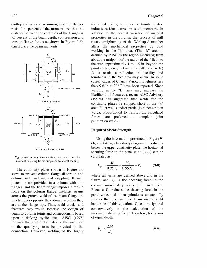
Typical internal forces on a panel zone areshown in Figure 9-6a; axial, shearing, andflexural forces are typically present in a panelzone. In this figure, continuity plates are shownin the column at the level of the beam flangesand the moments 1M and 2M represent
422 Chapter 9
earthquake actions. Assuming that the flangesresist 100 percent of the moment and that thedistance between the centroids of the flanges is95 percent of the beam depth, compression andtension flange forces as shown in Figure 9-6bcan replace the beam moments.
Figure 9-6. Internal forces acting on a panel zone of amoment-resisting frame subjected to lateral loading
The continuity plates shown in Figure 9-6serve to prevent column flange distortion andcolumn web yielding and crippling. If suchplates are not provided in a column with thinflanges, and the beam flange imposes a tensileforce on the column flange, inelastic strainsacross the groove weld of the beam flange aremuch higher opposite the column web than theyare at the flange tips. Thus, weld cracks andfractures may result. Because the design ofbeam-to-column joints and connections is basedupon qualifying cyclic tests, AISC (1997)requires that continuity plates of the size usedin the qualifying tests be provided in theconnection. However, welding of the highly
restrained joints, such as continuity plates,induces residual stress in steel members. Inaddition to the normal variation of materialproperties in the column, the process of millrotary straightening of the W-shaped memberalters the mechanical properties by coldworking in the “k” area. (The “k” area isdefined by AISC as the region extending fromabout the midpoint of the radius of the fillet intothe web approximately 1 to 1.5 in. beyond thepoint of tangency between the fillet and web.)As a result, a reduction in ductility andtoughness in the “k” area may occur. In somecases, values of Charpy V-notch toughness lessthan 5 ft-lb at 70° F have been reported. Sincewelding in the “k” area may increase thelikelihood of fracture, a recent AISC Advisory(1997a) has suggested that welds for thecontinuity plates be stopped short of the “k”area. Fillet welds and/or partial joint penetrationwelds, proportioned to transfer the calculatedforces, are preferred to complete jointpenetration welds.
Required Shear Strength
Using the information presented in Figure 9-6b, and taking a free-body diagram immediatelybelow the upper continuity plate, the horizontalshearing force in the panel zone ( pzV ) can becalculated as
c
bb
pz Vd
M
d
MV −+=
2
2
1
1
95.095.0 (9-8)
where all terms are defined above and in thefigure, and cV is the shearing force in thecolumn immediately above the panel zone.Because cV reduces the shearing force in thepanel zone, and its magnitude is substantiallysmaller than the first two terms on the righthand side of this equation, cV can be ignoredconservatively in the calculation of themaximum shearing force. Therefore, for beamsof equal depth,
bpz d
MV
∆≈ (9-9)

9. Seismic Design of Steel Structures 423
where )( 21 MMM +=∆ is the unbalancedbeam moment.
Prior to the publication of the 1988 UniformBuilding Code (ICBO 1988), panel zones weredesigned to remain elastic for pMMM == 21 ,
where pM is the nominal plastic moment of
the beam under consideration. The strength ofthe panel zone at first yield was computed as
wcyc AF55.0 , where ycF is the nominal yield
strength of the column and wcA is the area of
the column web (= cwctd ). This designprocedure was intended to produce strong panelzones such that yielding in the moment-resisting frame was minimized in the panelzone region.
Both the 1988 Uniform Building Code andthe 1992 AISC Seismic Provisions relaxed thedesign provisions for panel zone regions andpermitted intermediate strength panel zones andminimum strength panel zones. Previous studiesby Krawinkler et al. (1975) had shown thatpanel zone yielding could dissipate a largeamount of energy in a stable manner.Intermediate and minimum strength panel zoneswere introduced to encourage panel zoneyielding. According to the 1992 AISC SeismicProvisions, intermediate strength panel zoneswere designed for
gp MMM 2−=∆ ∑ (9-10)
where Mg is the gravity moment for onebeam. If the gravity moment is taken to be 20percent of the plastic moment, the aboveequation gives pMM Σ=∆ 8.0 . Minimum
strength panel zones were allowed for a valueof pE MMM Σ≤Σ=∆ 8.0 , where the
unbalanced beam moment produced by theprescribed design seismic forces is
)( 21 EEE MMM +=Σ . It has been shown (Tsaiand Popov 1988) that steel moment frames withintermediate- or minimum-strength panel zonesare likely to have a substantially smalleroverstrength factor, oΩ , than those with strongpanel zones. In addition, the lateral stiffness of
an intermediate- or minimum-strength panel-zone frame can be significantly smaller thanthat computed using a mathematical modelbased on centerline dimensions.
Current AISC provisions (AISC 1997)require the use of oΩ equal to 3.0 (see Table 9-1) for beam moments induced by the designearthquake loads. It also replaces the nominalplastic moment by the expected plastic momentand prescribes that the required strength of apanel zone need not exceed the shear force
determined from ∑ *8.0 pbM , where ∑ *pbM is
the sum of the beam moment(s) at theintersection of the beam and column
centrelines. ( ∑ *pbM is determined by
summing the projections of the expected beamflexural strength(s) at the plastic hingelocation(s) to the column centreline.) That is,the panel zone shall be designed for thefollowing unbalanced moment:
*o 8.0 pbE MMM Σ≤ΣΩ=∆ (9-11)
Substituting Eq. (9-11) into Eq. (9-9) wouldgive the required shear strength in the panelzone.
Post-Yield Strength and DetailingRequirements
The 1992 AISC equation for calculating thedesign shear strength of a panel zone ( nv Vφ ,where vφ =0.75) was based on the work ofKrawinkler et al. (1975):
+φ=φ
pcb
cfcfpcycvnv tdd
tbtdFV
23160.0 (9-12)
where cd is the depth of the column, pt is
the total thickness of the panel zone, includingdoubler plates ( cwp tt = if no doubler plates are
present), cfb is the width of the column flange,
cft is the thickness of the column flange, and
cd is the depth of the column. The second term

424 Chapter 9
in the parentheses represents the contribution ofcolumn flanges (assumed to be linearly elastic)to the shear strength of the panel zone. Theequation used to calculate Vn assumes a level ofshear strain of yγ4 in the panel zone, where yγis the yield shearing strain.
A panel zone must also be checked for aminimum thickness ( t ) to prevent prematurelocal buckling under large inelastic sheardeformations:
90
)( zz wdt
+= (9-13)
In this empirical equation, zd is the depth ofthe panel zone between the continuity plates,and zw is the width of the panel zone betweenthe column flanges. If doubler plates are used tosatisfy this equation for t , the plates must beplug welded to the column web such that theplates do not buckle independently of the web.
If used, doubler plates must be welded to thecolumn flanges using either a complete jointpenetration groove weld or a fillet weld thatdevelops the design shear strength of the fulldoubler plate thickness. When such plates arewelded directly to the column web and extendbeyond the panel zone, minimum weld size canbe used to connect the top and bottom edges tothe column web. However, because of the coldworking due to the rotary straightening practiceand the resulting variations of materialproperties exhibited in the column ”k” areas,the AISC Advisory (1997) suggested that, as aninterim measure, the design engineer increasethe column size to avoid the use of doublerplates.
9.2.6 Column Design
The column of an SMF must be designedper the LRFD Specifications (1997) as a beam-column to avoid axial yielding, buckling, andflexural yielding. Columns are routinely splicedby groove welding. Such connections arerequired to have sufficient strength to resist theimposed axial, shearing, and flexural forces
calculated using the specified loadcombinations. In addition, the column axialstrength should be sufficient to resist the axialforces produced by the special loadcombinations of Eqs. 9-4 and 9-5. Additionalstrength is required if either the welds arepartial penetration groove welds or the weldsare subjected to net tension forces. Columnsplices using fillet welds or partial jointpenetration groove welds shall not be locatedwithin 4 feet or one-half the column clearheight of beam-to-column connections, whichis less.
Special moment frames are designed usingthe strong column-weak beam philosophybecause such an approach improves the energydissipation capacity of the frame, promotesplastic hinge formation in the beams, increasesthe seismic resistance of the frame, andostensibly prevents the formation of a soft storymechanism. Seismic regulations seek to achievea strong column-weak beam system by ensuringthat, at a beam-to-column connection, the sumof the column plastic moments exceeds the sumof the beam plastic moments. With fewexceptions, AISC (1997) requires that:
0.1*
*
>∑∑
pb
pc
M
M(9-14)
where ∑ *pcM is the sum of the moment
capacities in the columns above and below thejoint at the intersection of the beam and column
centerlines, and ∑ *pbM is the sum of the
moment demands in the beams at theintersection of the beam and columncenterlines.
The value of ∑ *pcM is determined by
summing the projections of the nominalflexural strength of the columns above andbelow the connection to the beam centerline,with a reduction for the axial force in the
column. Σ *pcM can be conservatively
approximated as )/( gucycc APFZ −∑ , where
Ag is the gross area of the column, Puc is therequired column compressive strength, Zc is the
9. Seismic Design of Steel Structures 425
plastic section modulus of the column, and Fyc
is the minimum specified yield strength of
column. The value of ∑ *pbM is calculated by
summing the projection of the expected beamflexural strengths at the plastic hinge locations
to the column. ∑ *pbM can be approximated as
)1.1( vyy MZFR +∑ , where Z is the plastic
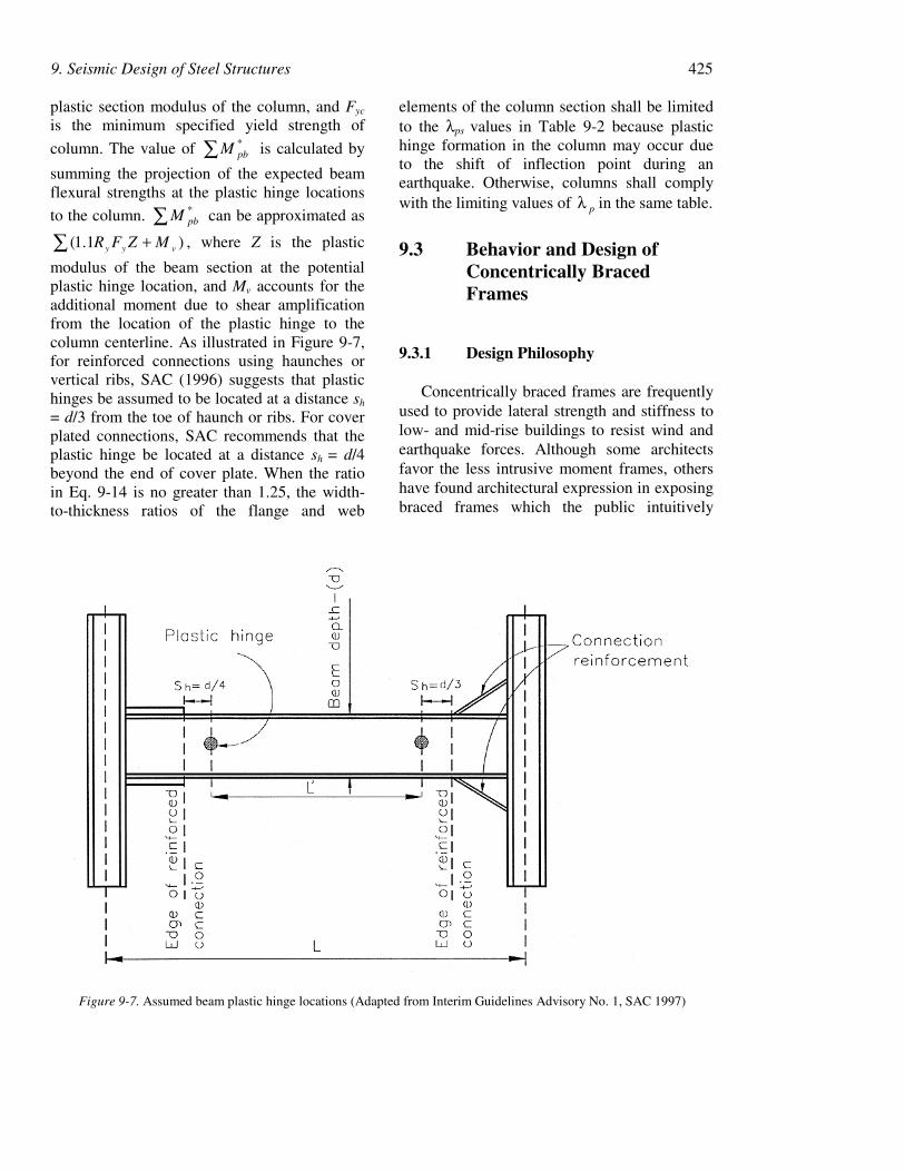
modulus of the beam section at the potentialplastic hinge location, and Mv accounts for theadditional moment due to shear amplificationfrom the location of the plastic hinge to thecolumn centerline. As illustrated in Figure 9-7,for reinforced connections using haunches orvertical ribs, SAC (1996) suggests that plastichinges be assumed to be located at a distance sh
= d/3 from the toe of haunch or ribs. For coverplated connections, SAC recommends that theplastic hinge be located at a distance sh = d/4beyond the end of cover plate. When the ratioin Eq. 9-14 is no greater than 1.25, the width-to-thickness ratios of the flange and web
elements of the column section shall be limitedto the λps values in Table 9-2 because plastichinge formation in the column may occur dueto the shift of inflection point during anearthquake. Otherwise, columns shall complywith the limiting values of pλ in the same table.
9.3 Behavior and Design ofConcentrically BracedFrames
9.3.1 Design Philosophy
Concentrically braced frames are frequentlyused to provide lateral strength and stiffness tolow- and mid-rise buildings to resist wind andearthquake forces. Although some architectsfavor the less intrusive moment frames, othershave found architectural expression in exposingbraced frames which the public intuitively
Figure 9-7. Assumed beam plastic hinge locations (Adapted from Interim Guidelines Advisory No. 1, SAC 1997)
426 Chapter 9
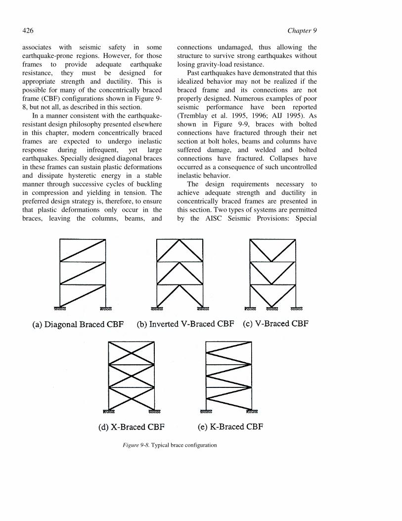
associates with seismic safety in someearthquake-prone regions. However, for thoseframes to provide adequate earthquakeresistance, they must be designed forappropriate strength and ductility. This ispossible for many of the concentrically bracedframe (CBF) configurations shown in Figure 9-8, but not all, as described in this section.
In a manner consistent with the earthquake-resistant design philosophy presented elsewherein this chapter, modern concentrically bracedframes are expected to undergo inelasticresponse during infrequent, yet largeearthquakes. Specially designed diagonal bracesin these frames can sustain plastic deformationsand dissipate hysteretic energy in a stablemanner through successive cycles of bucklingin compression and yielding in tension. Thepreferred design strategy is, therefore, to ensurethat plastic deformations only occur in thebraces, leaving the columns, beams, and
connections undamaged, thus allowing thestructure to survive strong earthquakes withoutlosing gravity-load resistance.
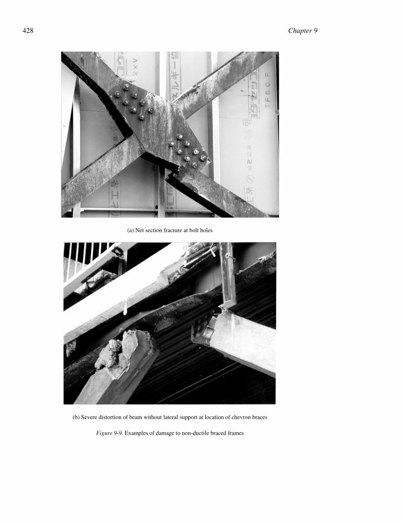
Past earthquakes have demonstrated that thisidealized behavior may not be realized if thebraced frame and its connections are notproperly designed. Numerous examples of poorseismic performance have been reported(Tremblay et al. 1995, 1996; AIJ 1995). Asshown in Figure 9-9, braces with boltedconnections have fractured through their netsection at bolt holes, beams and columns havesuffered damage, and welded and boltedconnections have fractured. Collapses haveoccurred as a consequence of such uncontrolledinelastic behavior.
The design requirements necessary toachieve adequate strength and ductility inconcentrically braced frames are presented inthis section. Two types of systems are permittedby the AISC Seismic Provisions: Special
Figure 9-8. Typical brace configuration
9. Seismic Design of Steel Structures 427
Concentrically Braced Frames (SCBs) andOrdinary Concentrically Braced Frames(OCBFs). The emphasis herein is on the SCBF,which is designed for stable inelasticperformance using a response modificationfactor, R, of 6. Some of the more stringentductile detailing requirements are relaxed forthe OCBFs because it is assumed that theseframes will be subjected to smaller inelasticdeformation demands due to the use of asmaller response modification factor. However,if an earthquake greater than that considered fordesign occurs, SCBFs are expected to performbetter than OCBFs because of theirsubstantially improved deformation capacity.
9.3.2 Hysteretic Energy DissipationCapacity of Braces
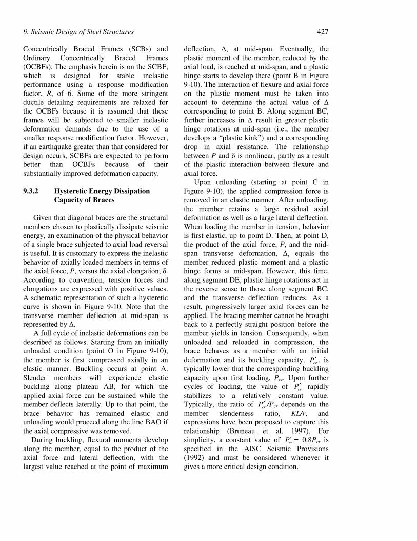
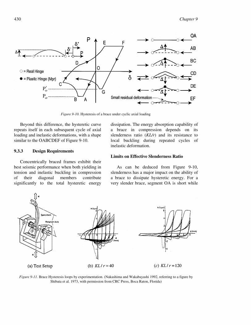
Given that diagonal braces are the structuralmembers chosen to plastically dissipate seismicenergy, an examination of the physical behaviorof a single brace subjected to axial load reversalis useful. It is customary to express the inelasticbehavior of axially loaded members in terms ofthe axial force, P, versus the axial elongation, δ.According to convention, tension forces andelongations are expressed with positive values.A schematic representation of such a hystereticcurve is shown in Figure 9-10. Note that thetransverse member deflection at mid-span isrepresented by ∆.
A full cycle of inelastic deformations can bedescribed as follows. Starting from an initiallyunloaded condition (point O in Figure 9-10),the member is first compressed axially in anelastic manner. Buckling occurs at point A.Slender members will experience elasticbuckling along plateau AB, for which theapplied axial force can be sustained while themember deflects laterally. Up to that point, thebrace behavior has remained elastic andunloading would proceed along the line BAO ifthe axial compressive was removed.
During buckling, flexural moments developalong the member, equal to the product of theaxial force and lateral deflection, with thelargest value reached at the point of maximum
deflection, ∆, at mid-span. Eventually, theplastic moment of the member, reduced by theaxial load, is reached at mid-span, and a plastichinge starts to develop there (point B in Figure9-10). The interaction of flexure and axial forceon the plastic moment must be taken intoaccount to determine the actual value of ∆corresponding to point B. Along segment BC,further increases in ∆ result in greater plastichinge rotations at mid-span (i.e., the memberdevelops a “plastic kink”) and a correspondingdrop in axial resistance. The relationshipbetween P and δ is nonlinear, partly as a resultof the plastic interaction between flexure andaxial force.
Upon unloading (starting at point C inFigure 9-10), the applied compression force isremoved in an elastic manner. After unloading,the member retains a large residual axialdeformation as well as a large lateral deflection.When loading the member in tension, behavioris first elastic, up to point D. Then, at point D,the product of the axial force, P, and the mid-span transverse deformation, ∆, equals themember reduced plastic moment and a plastichinge forms at mid-span. However, this time,along segment DE, plastic hinge rotations act inthe reverse sense to those along segment BC,and the transverse deflection reduces. As aresult, progressively larger axial forces can beapplied. The bracing member cannot be broughtback to a perfectly straight position before themember yields in tension. Consequently, whenunloaded and reloaded in compression, thebrace behaves as a member with an initialdeformation and its buckling capacity, crP′ , istypically lower that the corresponding bucklingcapacity upon first loading, Pcr. Upon furthercycles of loading, the value of crP′ rapidlystabilizes to a relatively constant value.Typically, the ratio of crP′ /Pcr depends on themember slenderness ratio, KL/r, andexpressions have been proposed to capture thisrelationship (Bruneau et al. 1997). Forsimplicity, a constant value of crP′ = 0.8Pcr isspecified in the AISC Seismic Provisions(1992) and must be considered whenever itgives a more critical design condition.
428 Chapter 9
(a) Net section fracture at bolt holes
(b) Severe distortion of beam without lateral support at location of chevron braces
Figure 9-9. Examples of damage to non-ductile braced frames

429 Chapter 9
(c) Fracture of welded connection and web tear-out in brace
(d) Weld fracture
Figure 9-9 Examples of damage to Non-Ductile braced frames (continued)
430 Chapter 9
Beyond this difference, the hysteretic curverepeats itself in each subsequent cycle of axialloading and inelastic deformations, with a shapesimilar to the OABCDEF of Figure 9-10.
9.3.3 Design Requirements
Concentrically braced frames exhibit theirbest seismic performance when both yielding intension and inelastic buckling in compressionof their diagonal members contributesignificantly to the total hysteretic energy
dissipation. The energy absorption capability ofa brace in compression depends on itsslenderness ratio (KL/r) and its resistance tolocal buckling during repeated cycles ofinelastic deformation.
Limits on Effective Slenderness Ratio
As can be deduced from Figure 9-10,slenderness has a major impact on the ability ofa brace to dissipate hysteretic energy. For avery slender brace, segment OA is short while
Figure 9-10. Hysteresis of a brace under cyclic axial loading
Figure 9-11. Brace Hysteresis loops by experimentation. (Nakashima and Wakabayashi 1992, referring to a figure byShibata et al. 1973, with permission from CRC Press, Boca Raton, Florida)

9. Seismic Design of Steel Structures 431
segment AB is long, resulting in poor energydissipation capacity in compression. For stockybraces, the reverse is true, and segment AB(i.e., elastic buckling) may not exist.Slenderness has no impact on the energydissipation capability of braces in tension.
Typical hysteretic loops obtainedexperimentally for axially loaded members ofintermediate and large slenderness ratios areshown in Figure 9-11, where the parameter λ(= EFrKl y /)/( π ) is a non-dimensionalslenderness ratio (Nakashima and Wakabayashi1992). Schematic illustrations of simplifiedhysteresis loops for short, intermediate and longbraces are shown in Figure 9-12.
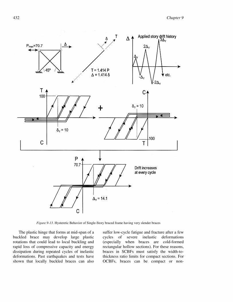
Very slender brace members (such as barsor plates) can result from a practice calledtension-only design, often used prior to thepromulgation of modern seismic provisions forsteel buildings, and still used in non-seismicregions. In that design approach, the tensionbrace is sized to resist all the lateral loads, andthe contribution of the buckled compressionbrace is ignored. While tension-only designmay be acceptable for wind resistance, it is notpermissible for earthquake resistance. Asshown in Figure 9-13, braced frames with veryslender members must progressively drift
further and further to be able to dissipate thesame amount of energy at each cycle, perhapsleading to collapse due to second-order effects.
Seismic detailing provisions typically limitbrace slenderness to prevent the above problemand to ensure good energy dissipation capacity.Many seismic codes require:
yFr
KL 720≤ (9-15)
where Fy is in ksi. For ASTM A992 or A572Grade 50 steel, this corresponds to an effectiveslenderness ratio of 102. Recently, the AISCSeismic Provisions (1997) have relaxed thislimit to:
yFr
KL 1000≤ (9-16)
for bracing members in SCBFs, but kept themore stringent limit of Eq. 9-15 for OCBFs.Nevertheless, the authors recommend the use ofEq. 9-15 for both SCBFs and OCBFs.
Limits on Width-to-Thickness Ratio
Figure 9-12. Schematic hysteretic behavior of braces of short, long, and intermediate slenderness (Nakashima andWakabayashi 1992, with permission from CRC Press, Boca Raton, Florida).
432 Chapter 9
The plastic hinge that forms at mid-span of abuckled brace may develop large plasticrotations that could lead to local buckling andrapid loss of compressive capacity and energydissipation during repeated cycles of inelasticdeformations. Past earthquakes and tests haveshown that locally buckled braces can also
suffer low-cycle fatigue and fracture after a fewcycles of severe inelastic deformations(especially when braces are cold-formedrectangular hollow sections). For these reasons,braces in SCBFs must satisfy the width-to-thickness ratio limits for compact sections. ForOCBFs, braces can be compact or non-
Figure 9-13. Hysteretic Behavior of Single-Story braced frame having very slender braces

9. Seismic Design of Steel Structures 433
compact, but not slender, i.e., tb / ≤ λr perLRFD Specification. Based on experimentalevidence, more stringent limits are specified forsome types of structural shapes. In particular,the width-to-thickness ratio of angles (b/t), theoutside diameter to wall thickness ratio ofunstiffened circular hollow sections (D/t), andthe outside width to wall thickness ratio ofunstiffened rectangular sections must not
exceed 52/ yF , 1300/Fy, and 110/ yF ,
respectively (see Table 9-2). Note that theAISC Seismic Provisions (1997) define b forrectangular hollow sections as the “out-to-outwidth”, not the flat-width (= b−3t) as defined inthe AISC Specifications (AISC 1994).
Redundancy
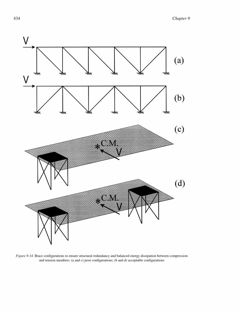
Energy dissipation by tension yielding ofbraces is more reliable than buckling of bracesin compression. To provide structuralredundancy and a good balance of energydissipation between compression and tensionmembers, structural configurations that dependpredominantly on the compression resistance ofbraces should be avoided. Examples of poorbraced frames layout are shown in Figure 9-14,together with recommended alternatives. Fourbraces in compression and only one brace intension resist the load applied on the 5-baybraced frame shown in Figure 9-14a. All bracesin the braced-core of Figure 9-14c are incompression to resist the torsional momentresulting from seismically-induced inertialforce acting at the center of mass. (Forsimplicity, columns resisting only gravity loadsare not shown in that figure.) Better designs areshown in Figures 9-14b and 9-14d for each ofthese cases, respectively.
Seismic design codes attempt to prevent theuse of non-redundant structural systems byrequiring that braces in a given line be deployedsuch that at least 30% of the total lateralhorizontal force acting along that line is resistedby tension braces, and at least 30% bycompression braces. Although the wording ofsuch clauses does not cover the case shown in
Figure 9-14c, the intent does. Codes generallywaive this requirement if nearly elasticresponse is expected during earthquakes,something achieved in the AISC SeismicProvisions by the special load conditionsdescribed in Section 9.1. Note that incalculating the strength of an OCBF, the AISCSeismic Provisions also require that φcPcr (=0.9φcPcr) be used instead of φcPcr, for thereasons described in the previous section. Thereis no such requirement for SCBFs, but theauthors prefer to observe this requirement forboth OCBFs and SCBFs, recognizing, however,that the tension brace may have sufficientstrength to accommodate the strengthdegradation of the compression brace uponrepeated cycling, and that such a forceredistribution may be considered whencalculating the strength of the braced panelusing φcPcr. This approach is not recommendedfor V- and inverted-V-types of OCBF.
9.3.4 Bracing Connections DesignRequirements
When a brace is in tension, net sectionfracture and block shear rupture at the end ofthe brace must be avoided. Likewise, the braceconnections to beams and columns must bestronger than the braces themselves. Usingcapacity design, calculation of brace strengthmust recognize that the expected yield strengthof the brace, Fye, will typically exceed itsspecified minimum yield strength, Fy (see Eq.9-6). Thus, connections must be designed toresist an axial force equal to RyFyAg. However,when plastic analysis is used to demonstratethat braces are unlikely to yield, connectionsmay be designed for the maximum forceobtained from such an analysis.
Connections must also be able to resist theforces due to buckling of the brace. If strongconnections permit the development of a plastichinge at each end of a brace, they should bedesigned to resist a moment equal to 1.1RyMp ofthe brace in the direction of buckling.Otherwise, the connecting elements willthemselves yield in flexure (such as gussets out
434 Chapter 9
Figure 9-14. Brace configurations to ensure structural redundancy and balanced energy dissipation between compressionand tension members: (a and c) poor configurations; (b and d) acceptable configurations
9. Seismic Design of Steel Structures 435
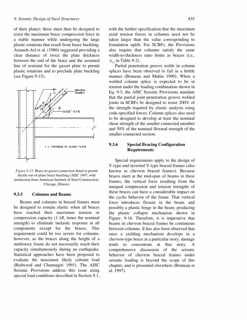
of their plane); these must then be designed toresist the maximum brace compression force ina stable manner while undergoing the largeplastic rotations that result from brace buckling.Astaneh-Asl et al. (1986) suggested providing aclear distance of twice the plate thicknessbetween the end of the brace and the assumedline of restraint for the gusset plate to permitplastic rotations and to preclude plate buckling(see Figure 9-15).
Figure 9-15. Brace-to-gusset connection detail to permitductile out-of-plane brace buckling (AISC 1997, with
permission from American Institute of Steel Construction,Chicago, Illinois)
9.3.5 Columns and Beams
Beams and columns in braced frames mustbe designed to remain elastic when all braceshave reached their maximum tension orcompression capacity (1.1Ry times the nominalstrength) to eliminate inelastic response in allcomponents except for the braces. Thisrequirement could be too severe for columns,however, as the braces along the height of amultistory frame do not necessarily reach theircapacity simultaneously during an earthquake.Statistical approaches have been proposed toevaluate the maximum likely column load(Redwood and Channagiri 1991). The AISCSeismic Provisions address this issue usingspecial load conditions described in Section 9.1,
with the further specification that the maximumaxial tension forces in columns need not betaken larger than the value corresponding tofoundation uplift. For SCBFs, the Provisionsalso require that columns satisfy the samewidth-to-thickness ratio limits as braces (i.e.,
psλ in Table 9-2).Partial penetration groove welds in column
splices have been observed to fail in a brittlemanner (Bruneau and Mahin 1990). When awelded column splice is expected to be intension under the loading combination shown inEq. 9-5, the AISC Seismic Provisions mandatethat the partial joint penetration groove weldedjoints in SCBFs be designed to resist 200% ofthe strength required by elastic analysis usingcode-specified forces. Column splices also needto be designed to develop at least the nominalshear strength of the smaller connected memberand 50% of the nominal flexural strength of thesmaller connected section.
9.3.6 Special Bracing ConfigurationRequirements
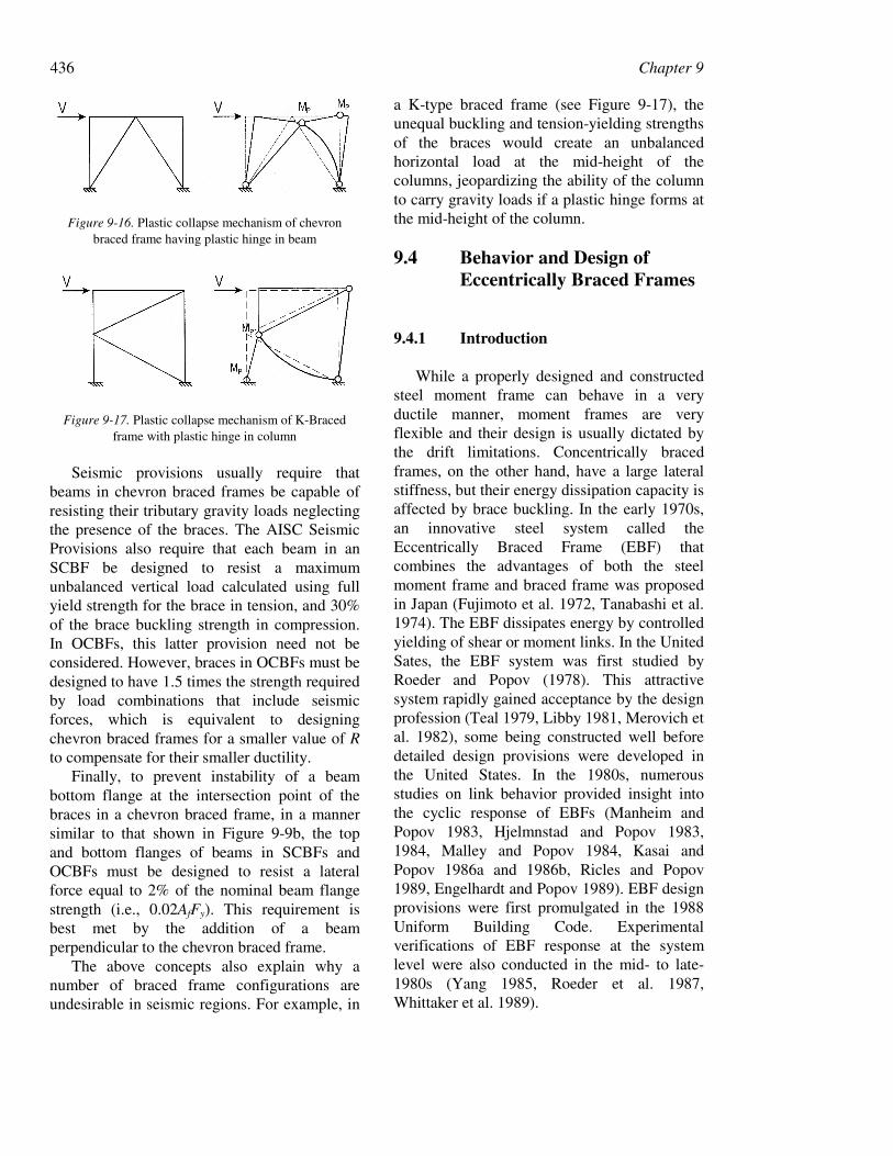
Special requirements apply to the design ofV-type and inverted V-type braced frames (alsoknown as chevron braced frames). Becausebraces meet at the mid-span of beams in theseframes, the vertical force resulting from theunequal compression and tension strengths ofthese braces can have a considerable impact onthe cyclic behavior of the frame. That verticalforce introduces flexure in the beam, andpossibly a plastic hinge in the beam, producingthe plastic collapse mechanism shown inFigure. 9-16. Therefore, it is imperative thatbeams in chevron braced frames be continuousbetween columns. It has also been observed thatonce a yielding mechanism develops in achevron-type brace at a particular story, damagetends to concentrate at that story. Acomprehensive discussion of the seismicbehavior of chevron braced frames underseismic loading is beyond the scope of thischapter, and is presented elsewhere (Bruneau etal. 1997).
436 Chapter 9
Figure 9-16. Plastic collapse mechanism of chevronbraced frame having plastic hinge in beam
Figure 9-17. Plastic collapse mechanism of K-Bracedframe with plastic hinge in column
Seismic provisions usually require thatbeams in chevron braced frames be capable ofresisting their tributary gravity loads neglectingthe presence of the braces. The AISC SeismicProvisions also require that each beam in anSCBF be designed to resist a maximumunbalanced vertical load calculated using fullyield strength for the brace in tension, and 30%of the brace buckling strength in compression.In OCBFs, this latter provision need not beconsidered. However, braces in OCBFs must bedesigned to have 1.5 times the strength requiredby load combinations that include seismicforces, which is equivalent to designingchevron braced frames for a smaller value of Rto compensate for their smaller ductility.
Finally, to prevent instability of a beambottom flange at the intersection point of thebraces in a chevron braced frame, in a mannersimilar to that shown in Figure 9-9b, the topand bottom flanges of beams in SCBFs andOCBFs must be designed to resist a lateralforce equal to 2% of the nominal beam flangestrength (i.e., 0.02AfFy). This requirement isbest met by the addition of a beamperpendicular to the chevron braced frame.
The above concepts also explain why anumber of braced frame configurations areundesirable in seismic regions. For example, in
a K-type braced frame (see Figure 9-17), theunequal buckling and tension-yielding strengthsof the braces would create an unbalancedhorizontal load at the mid-height of thecolumns, jeopardizing the ability of the columnto carry gravity loads if a plastic hinge forms atthe mid-height of the column.
9.4 Behavior and Design ofEccentrically Braced Frames
9.4.1 Introduction
While a properly designed and constructedsteel moment frame can behave in a veryductile manner, moment frames are veryflexible and their design is usually dictated bythe drift limitations. Concentrically bracedframes, on the other hand, have a large lateralstiffness, but their energy dissipation capacity isaffected by brace buckling. In the early 1970s,an innovative steel system called theEccentrically Braced Frame (EBF) thatcombines the advantages of both the steelmoment frame and braced frame was proposedin Japan (Fujimoto et al. 1972, Tanabashi et al.1974). The EBF dissipates energy by controlledyielding of shear or moment links. In the UnitedSates, the EBF system was first studied byRoeder and Popov (1978). This attractivesystem rapidly gained acceptance by the designprofession (Teal 1979, Libby 1981, Merovich etal. 1982), some being constructed well beforedetailed design provisions were developed inthe United States. In the 1980s, numerousstudies on link behavior provided insight intothe cyclic response of EBFs (Manheim andPopov 1983, Hjelmnstad and Popov 1983,1984, Malley and Popov 1984, Kasai andPopov 1986a and 1986b, Ricles and Popov1989, Engelhardt and Popov 1989). EBF designprovisions were first promulgated in the 1988Uniform Building Code. Experimentalverifications of EBF response at the systemlevel were also conducted in the mid- to late-1980s (Yang 1985, Roeder et al. 1987,Whittaker et al. 1989).
9. Seismic Design of Steel Structures 437
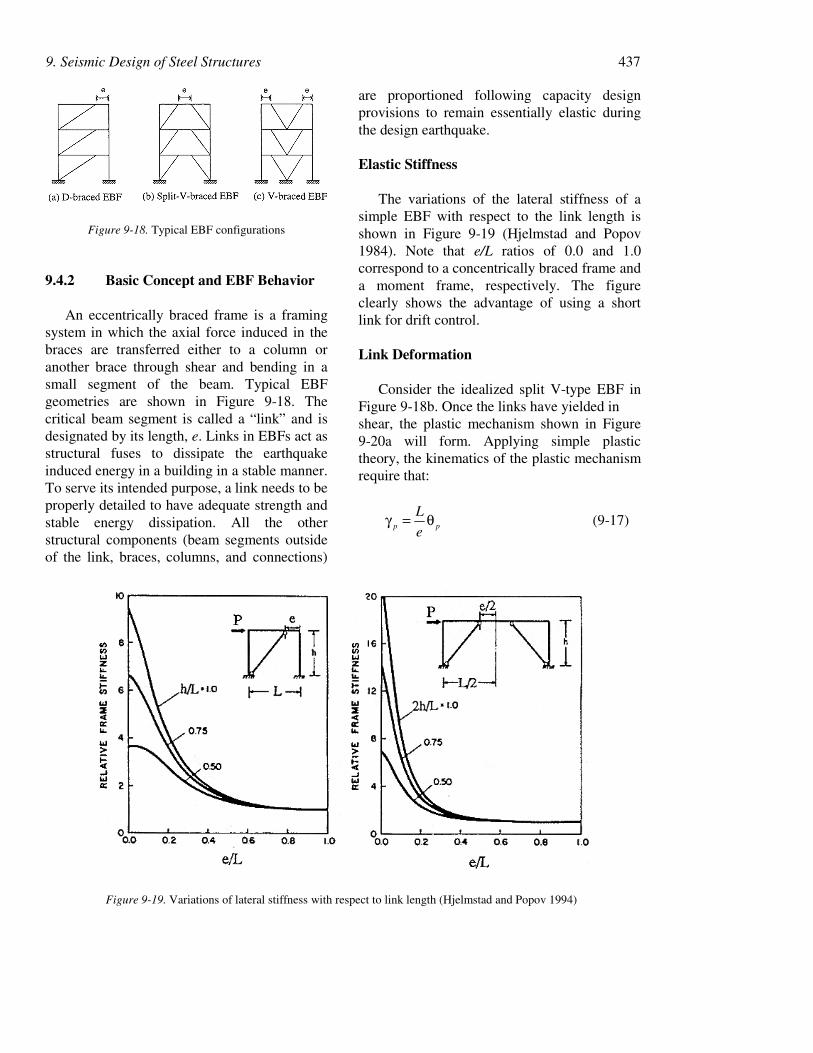
Figure 9-18. Typical EBF configurations
9.4.2 Basic Concept and EBF Behavior
An eccentrically braced frame is a framingsystem in which the axial force induced in thebraces are transferred either to a column oranother brace through shear and bending in asmall segment of the beam. Typical EBFgeometries are shown in Figure 9-18. Thecritical beam segment is called a “link” and isdesignated by its length, e. Links in EBFs act asstructural fuses to dissipate the earthquakeinduced energy in a building in a stable manner.To serve its intended purpose, a link needs to beproperly detailed to have adequate strength andstable energy dissipation. All the otherstructural components (beam segments outsideof the link, braces, columns, and connections)
are proportioned following capacity designprovisions to remain essentially elastic duringthe design earthquake.
Elastic Stiffness
The variations of the lateral stiffness of asimple EBF with respect to the link length isshown in Figure 9-19 (Hjelmstad and Popov1984). Note that e/L ratios of 0.0 and 1.0correspond to a concentrically braced frame anda moment frame, respectively. The figureclearly shows the advantage of using a shortlink for drift control.
Link Deformation
Consider the idealized split V-type EBF inFigure 9-18b. Once the links have yielded inshear, the plastic mechanism shown in Figure9-20a will form. Applying simple plastictheory, the kinematics of the plastic mechanismrequire that:
pp e
L θ=γ (9-17)
Figure 9-19. Variations of lateral stiffness with respect to link length (Hjelmstad and Popov 1994)
438 Chapter 9
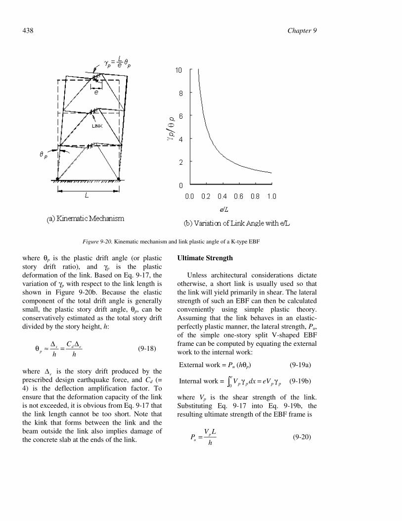
where θp is the plastic drift angle (or plasticstory drift ratio), and γp is the plasticdeformation of the link. Based on Eq. 9-17, thevariation of γp with respect to the link length isshown in Figure 9-20b. Because the elasticcomponent of the total drift angle is generallysmall, the plastic story drift angle, θp, can beconservatively estimated as the total story driftdivided by the story height, h:
h
C
heds
p
∆=∆≈θ (9-18)
where e∆ is the story drift produced by theprescribed design earthquake force, and Cd (=4) is the deflection amplification factor. Toensure that the deformation capacity of the linkis not exceeded, it is obvious from Eq. 9-17 thatthe link length cannot be too short. Note thatthe kink that forms between the link and thebeam outside the link also implies damage ofthe concrete slab at the ends of the link.
Ultimate Strength
Unless architectural considerations dictateotherwise, a short link is usually used so thatthe link will yield primarily in shear. The lateralstrength of such an EBF can then be calculatedconveniently using simple plastic theory.Assuming that the link behaves in an elastic-perfectly plastic manner, the lateral strength, Pu,of the simple one-story split V-shaped EBFframe can be computed by equating the externalwork to the internal work:
External work = Pu (hθp) (9-19a)
Internal work = ppp
e
p eVdxV γ=γ∫0 (9-19b)
where Vp is the shear strength of the link.Substituting Eq. 9-17 into Eq. 9-19b, theresulting ultimate strength of the EBF frame is
h
LVP p
u = (9-20)
Figure 9-20. Kinematic mechanism and link plastic angle of a K-type EBF

9. Seismic Design of Steel Structures 439
As long as the link yields in shear, the aboveequation shows that the ultimate strength isindependent of the link length. This simpleplastic theory can also be applied to multistoryframes (Kasai and Popov 1985).
Once the link length exceeds a thresholdvalue, flexure and shear dominates the linkstrength. The ultimate strength of the framethen decreases with an increase in link length.Figure 9-21 illustrates the strength variations.This figure also indicates that the ultimatestrength of an EBF with short links issignificantly larger than that of a moment frame(i.e., e/L = 1.0).
Figure 9-21. Variations of EBF ultimate strength with e/L(Kasai and Popov 1985)
9.4.3 Link Behavior
Critical Length for Shear Link
Figure 9-22 shows the free-body diagram ofa link. Ignoring the effects of axial force andthe interaction between moment and shear inthe link, flexural hinges form at two ends of thelink when both MA and MB reach the plastic
moment, Mp. A shear hinge is said to formwhen the shear reaches Vp. The plastic momentand shear capacities are respectively computedas follows:
Mp = Fy Z (9-21a)
Vp = wfy ttdF )2(6.0 − (9-21b)
Figure 9-22. Link deformation and free-body diagram
A balanced yielding condition corresponds tothe simultaneous formation of flexural hingesand a shear hinge. The corresponding linklength is
p
p
V
Me
20 = (9-22)
In a short link ( 0ee ≤ ), a shear hinge will form.When 0ee > , a flexural (or moment) hingeforms at both ends of the link, and thecorresponding shear force is:
e
MV p2
= (9-23)
Based on plastic theory, Eq. 9-22 can bemodified slightly to include the effect ofinteraction between M and V. Nevertheless,experimental results indicated that theinteraction is weak and that such interaction canbe ignored (Kasai and Popov 196b). Test resultsalso showed that a properly stiffened short linkcan strain harden and develop a shear strengthequal to 1.5Vp. The end moments of a link thathas yielded in shear can continue to increase
440 Chapter 9
due to strain hardening and, therefore, flexuralhinges can develop. To avoid low-cycle fatiguefailure of the link flanges due to high strains,these end moments are limited to 1.2Mp, and themaximum length (e0 in Eq. 9-22) for a shearlink was modified as follows (Kasai and Popov1986b):
p
p
p
p
V
M
V
Me
6.1
5.1
)2.1(20 == (9-24)
Longer Links
Experimental results have shown that theinelastic deformation capacity of an EBF can begreatly reduced when long links ( 0ee > ) areused. Following the above logic, it can beshown that flexural hinges dominate the linkresponse when e is larger than pp VM /6.2 . In
the transition region where
pppp VMeVM /6.2/6.1 << , the link undergoes
simultaneous shear and flexural yielding(Engelhardt and Popov 1989). Figure 9-23classifies links in EBFs. Note that when longerlinks are used in the D-type or V-type EBF (seeFigure 9-18), the welded connection betweenthe link and the column is subjected to highmoments and it could be vulnerable to brittlefracture if detailed similar to the connectionsthat failed during the Northridge earthquake(see Section 9.2).
Figure 9-23. Classification of links
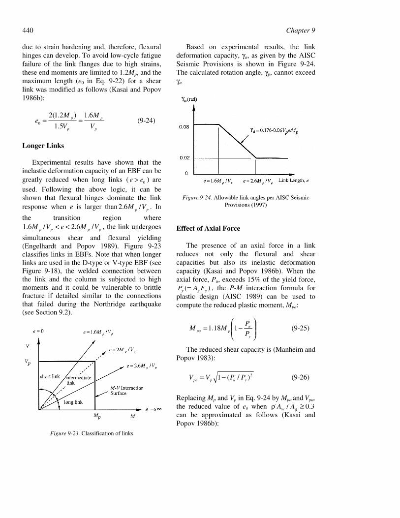
Based on experimental results, the linkdeformation capacity, γa, as given by the AISCSeismic Provisions is shown in Figure 9-24.The calculated rotation angle, γp, cannot exceedγa.
Figure 9-24. Allowable link angles per AISC SeismicProvisions (1997)
Effect of Axial Force
The presence of an axial force in a linkreduces not only the flexural and shearcapacities but also its inelastic deformationcapacity (Kasai and Popov 1986b). When theaxial force, Pu, exceeds 15% of the yield force,
)( ygy FAP = , the P-M interaction formula forplastic design (AISC 1989) can be used tocompute the reduced plastic moment, Mpa:
−=
y
uppa P
PMM 118.1 (9-25)
The reduced shear capacity is (Manheim andPopov 1983):
2)/(1 yuppa PPVV −= (9-26)
Replacing Mp and Vp in Eq. 9-24 by Mpa and Vpa,the reduced value of e0 when 3.0/ ≥ρ′ gw AAcan be approximated as follows (Kasai andPopov 1986b):

9. Seismic Design of Steel Structures 441
p
p
g
w
V
M
A
Ae
6.15.015.10
ρ′−= (9-27)
where VP /=ρ′ , and wfw ttdA )2( −= . Thecorrection is unnecessary if 3.0/ <ρ′
gw AA , inwhich case the AISC Seismic Provisions (1997)require that the link length shall not exceed thatgiven by Eq. 9-24.
Effect of Concrete Slab
Research conducted on composite linksshowed that composite action can significantlyincrease the link shear capacity during the firstcycles of large inelastic deformations.However, composite action deteriorates rapidlyin subsequent cycles due to local concrete floordamage at both ends of the link (Ricles andPopov 1989). For design purposes, it isconservative to ignore the contribution ofcomposite action for calculating the link shearstrength. But the overstrength produced by thecomposite slab effect needs to be consideredwhen estimating the maximum forces that theshear link imposes to other structuralcomponents (Whittaker et al. 1989).
Link Detailing
Full-depth web stiffeners must be placedsymmetrically on both sides of the link web atthe diagonal brace ends of the link. These endstiffeners are required to have a combinedwidth not less than (bf −2tw) and a thickness notless than 0.75tw nor 3/8 inch, whichever islarger.
The link section needs to satisfy the samecompactness requirement as the beam sectionfor special moment frames. Further, the linkneeds to be stiffened in order to delay the onsetof web buckling and to prevent flange localbuckling. The stiffening requirement isdependent on the length of link (see Figure 9-23). For a shear link with pp VMe /6.1≤ , a
relationship among the link web deformationangle, the web panel aspect ratio as well as thebeam web slenderness ratio was developed
(Kasai and Popov 1986a). A conservativeapproximation of the relationship follows:
5
dtCa wB −= (9-28)
where a = stiffener spacing, d = link depth, tw =link web thickness, and CB = 56, 38, and 29 for
pγ = 0.03, 0.06, and 0.09 radian, respectively.These CB values are slightly modified and areadopted in the AISC Seismic Provisions (1997)as follows: (1) When pp VMe /6.1≤ , intermediate
stiffeners are needed per Eq. 9-28, but thecoefficient CB is a function of the deformationdemand; the relationship between CB
and pγ implied by the AISC Seismic Provisions
is shown in Figure 9-25.(2) When pppp VMeVM /5/6.2 ≤≤ ,
intermediate stiffeners shall be provided at adistance 1.5bf from each end of the link tocontrol flange local buckling.
(3) When pppp V/M.eV/M. 6261 ≤≤ ,intermediate stiffeners satisfying therequirements of both Cases 1 and 2 are needed.
(4) When pp VMe /5> , intermediatestiffeners are not required.
Intermediate link web stiffeners must be fulldepth. While two-sided stiffeners are requiredat the end of the link where the diagonal braceintersects the link, intermediate stiffenersplaced on one side of the link web are sufficientfor links less than 25 inches in depth. Filletwelds connecting a link stiffener
Figure 9-25. Variation of CB
442 Chapter 9
to the link web shall have a design strength toresist a force of AstFy, where Ast is the stiffenerarea. The design strength of fillet weldsfastening the stiffener to the flanges shall beadequate to resist a force of AstFy/4.
Lateral Bracing of Link
To ensure stable hysteresis, a link must belaterally braced at each end to avoid out-of-plane twisting. Lateral bracing also stabilizesthe eccentric bracing and the beam segmentoutside the link. The concrete slab alone cannotbe relied upon to provide lateral bracing.Therefore, both top and bottom flanges of thelink beam must be braced. The bracing shouldbe designed for 6 percent of the expected linkflange strength, RyFybf tf.
9.4.4 Capacity Design of OtherStructural Components
Links in an EBF are designated as structuralfuses and are sized for code-specified designseismic forces. All other elements (beamsegments outside the link, braces, columns, andconnections) are then designed for the forcesgenerated by the actual (or expected) capacityof the links rather than the code-specifieddesign seismic forces. The capacity designconcept thus requires that the computation ofthe link strength not only be based on theexpected yield strength of the steel but alsoincludes the consideration of strain-hardeningand overstrength due to composite action of theslab.
Diagonal Brace
The required axial and flexural strength ofthe diagonal brace shall be those generated bythe expected shear strength of the link RyVn
increased by 125 percent to account for strain-hardening. The nominal shear capacity, Vn, isthe lesser of Vp or 2Mp/e. Although braces arenot expected to experience buckling, the AISCSeismic Provisions take a conservativeapproach by requiring that a compact section( pλ<λ ) be used for the brace.
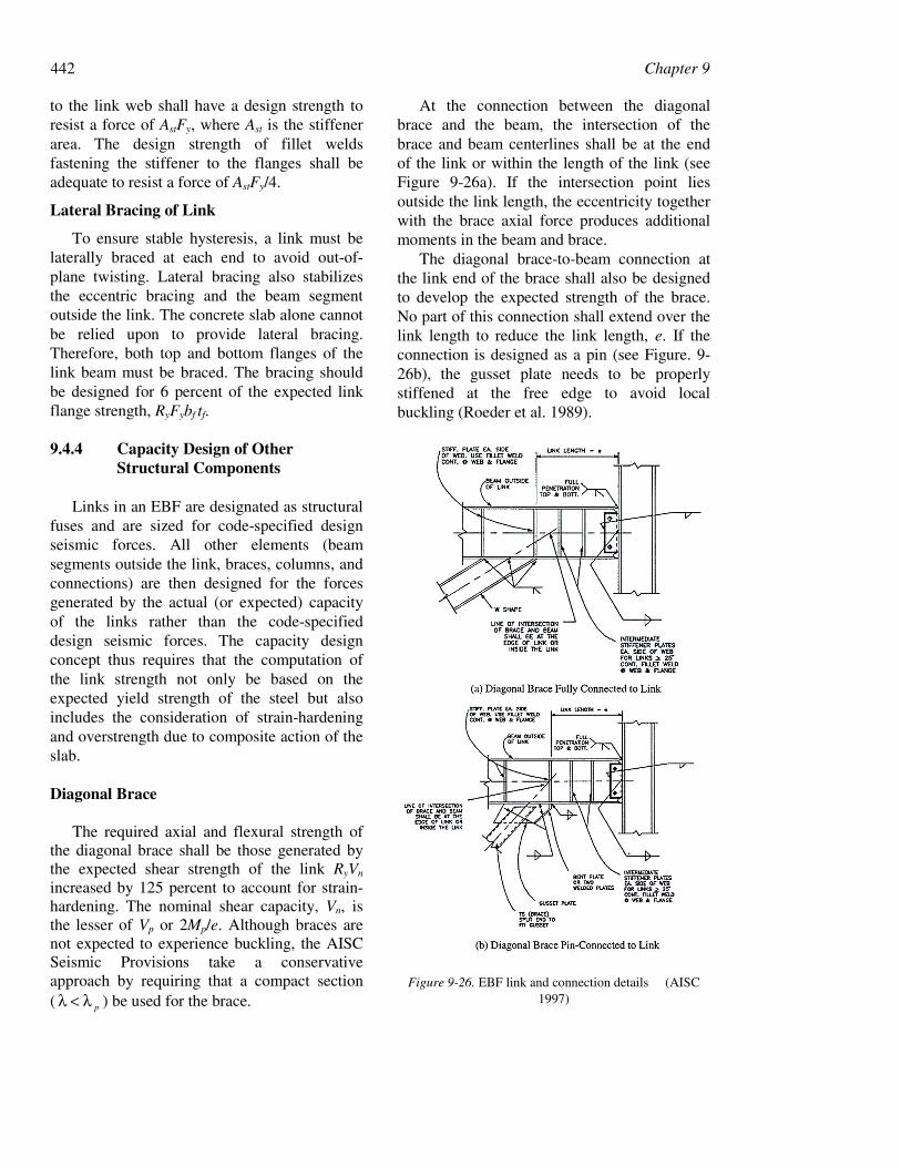
At the connection between the diagonalbrace and the beam, the intersection of thebrace and beam centerlines shall be at the endof the link or within the length of the link (seeFigure 9-26a). If the intersection point liesoutside the link length, the eccentricity togetherwith the brace axial force produces additionalmoments in the beam and brace.
The diagonal brace-to-beam connection atthe link end of the brace shall also be designedto develop the expected strength of the brace.No part of this connection shall extend over thelink length to reduce the link length, e. If theconnection is designed as a pin (see Figure. 9-26b), the gusset plate needs to be properlystiffened at the free edge to avoid localbuckling (Roeder et al. 1989).
Figure 9-26. EBF link and connection details (AISC1997)
9. Seismic Design of Steel Structures 443
Link-to-Column Connections
Of the common EBF configurations shownin Figure 9-18, it is highly desirable to use thesplit V-braced EBF in order to avoid themoment connection between the link andcolumn. Prior to the 1994 Northridgeearthquake, test results showed that the fullyrestrained welded connection between thecolumn and the link (especially longer links) isvulnerable to brittle fracture similar to thosefound in the beam-to-column momentconnections after the Northridge earthquake.Therefore, the AISC Seismic Provisions (1997)require that the deformation capacity of thelink-to-column connections be verified byqualifying cyclic tests. Test results shalldemonstrate that the link inelastic rotationcapacity is at least 20 percent greater than thatcalculated by Eq. 9-17.
When reinforcements like cover plates areused to reinforce the link-to-columnconnection, the link over the reinforced lengthmay not yield. Under such circumstances, thelink is defined as the segment between the endof the reinforcement and the brace connection.Cyclic testing is not needed when (1) theshortened link length does not exceed eo in Eq.9-24, and (2) the design strength of thereinforced connection is equal to or greater thanthe force produced by a shear force of 1.25 RyVn
in the link.Tests also demonstrated that the welded
connections of links to the weak-axis of acolumn were vulnerable to brittle fracture(Engelhardt and Popov 1989); this type ofconnection should be avoided.
Beam-to-Column Connection
For the preferred EBF configuration wherethe link is not adjacent to a column, a simpleframing connection between the beam and thecolumn is considered adequate if it providessome restraint against torsion in the beam. TheAISC Seismic Provisions stipulate that themagnitude of this torsion be calculated by
considering perpendicular forces equal to 2percent of the beam flange nominal strength,Fybf tf, applied in opposite directions on eachflange.
Beam Outside of Link
The link end moment is distributed betweenthe brace and the beam outside of the linkaccording to their relative stiffness. Inpreliminary design, it is conservative to assumethat all the link end moment is resisted by thebeam. The link end moment shall be calculatedusing 1.1 times the expected nominal shearstrength (RyVn) of the link. Because acontinuous member is generally used for boththe link and the beam outside the link, it is tooconservative to use the expected yield strength(RyFy) for estimating the force demandproduced by the link while the beam strength isbased on the nominal yield strength (Fy).Therefore, the AISC Seismic Provisions allowdesigners to increase the design strength of thebeam by a factor Ry.
The horizontal component of the braceproduces a significant axial force in the beam,particularly if the angle between the diagonalbrace and the beam is small. Therefore, thebeam outside the link needs to be designed as abeam-column. When lateral bracing is used toincrease the capacity of the beam-column, thisbracing must be designed to resist 2 percent ofthe beam flange nominal strength, Fybf tf.
Column
Using a capacity design approach, columnsin braced bays shall have a sufficient strength toresist the sum of gravity-load actions and themoments and axial forces generated by 1.1times the expected nominal strength (RyVn) ofthe link. This procedure assumes that all linkswill yield and reach their maximum strengthssimultaneously. Nevertheless, availablemultistory EBF test results showed that thispreferred yielding mechanism is difficult todevelop. For example, shaking table testing of a6-story reduced scale EBF model showed that
444 Chapter 9
links in the bottom two stories dissipated mostof the energy (Whittaker et al. 1989).Therefore, this design procedure may beappropriate for low-rise buildings and the upperstories of medium- and high-rise buildings butmay be too conservative in other instances.
The alternative design procedure permittedby the AISC Seismic Provisions is to amplifythe design seismic axial forces and moments incolumns by the overstrength factor, Ωo (= 2.0,see Table 9-1). See Eqs. 9-4 and 9-5 for theload combinations. The computed column
forces need not exceed those computed by thefirst procedure. Therefore, the first designprocedure will generally produce a moreconservative design for columns.
9.5 Design Examples
9.5.1 General
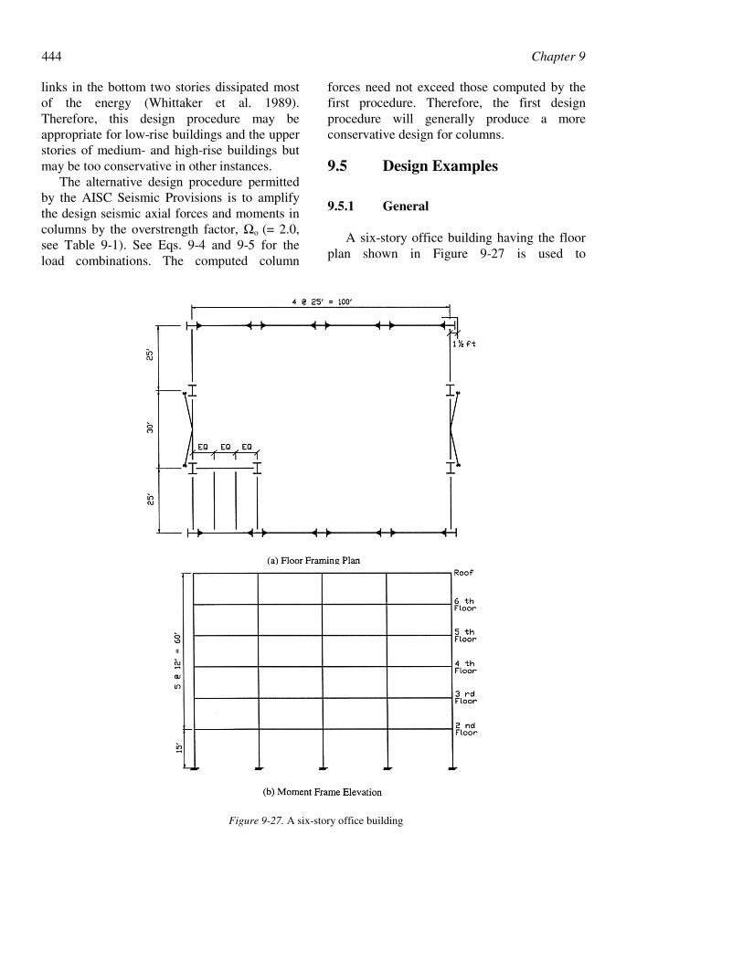
A six-story office building having the floorplan shown in Figure 9-27 is used to
Figure 9-27. A six-story office building
9. Seismic Design of Steel Structures 445
demonstrate the seismic design procedures. Thedesign follows the AISC Seismic Provisions(1997) and the Load and Resistance FactorDesign Specification for Structural SteelBuildings (1993). Special Moment-ResistingFrames (SMFs) are used in the E-W direction,and their design is presented in Section 9.5.2.Braced frames provide lateral load-resistance inthe N-S direction; these are designed as SpecialConcentrically Braced Frames (SCBFs) inSection 9.5.3 and Eccentrically Braced Frames(EBFs) in Section 9.5.4, respectively.
The design gravity loads are listed in Table9-3. The NEHRP Recommended Provisions(1997) are the basis for computing the designseismic forces. It is assumed that the building islocated in a high seismic region with thefollowing design parameters:
SS = 1.5 gS1 = 0.6 gSite Class = BI = 1.0 (Seismic User Group I)Seismic Design Category = D
The design response spectrum is shown inFigure 9-28.
The design follows the Equivalent LateralForce Procedure of the NEHRP RecommendedProvisions. The design base shear ratio, Cs, iscomputed as follows:
)/()/(1
IR
S
IRT
SC DSD
s ≤= (9-29)
where 1DS (= 0.4 g) and DSS (= 1.0 g) are thedesign spectral response accelerations at aperiod of 1.0 second and in the short periodrange, respectively. The values of R for thethree framing systems considered in thisexample are listed in Table 9-4. The NEHRPempirical period formula is used to compute theapproximate fundamental period, Ta:
4/3nTa hCT = (9-30)
where hn (ft) is the building height, and thecoefficient CT is equal to 0.035, 0.030, and 0.02for SMFs, EBFs, and SCBFs, respectively.Alternatively, the value of T obtained from adynamic analysis can be used in design, but theperiod thus obtained cannot be taken larger thanCuTa for the calculation of required structuralstrengths, where Cu = 1.2
Figure 9-28. Elastic design response spectrum
for this design example. To establish seismicforces for story drift computations, however,this upper limit is waived by the NEHRPRecommended Provisions. Recognizing that theanalytically predicted period of a multistorySMF is generally larger than CuTa, this upperbound value is used to compute the design baseshear ratio for preliminary design. Based on Eq.9-1, the design base shear ratios for the threetypes of frames are listed in Table 9-4.
The following two load combinations are tobe considered:
1.2D + 0.5L + 1.0E (9-31)
0.9D – 1.0E (9-32)
where E = ρ QE + 0.2 SDSD. The RedundancyFactor, ρ , is
13.1854925.0
202
202
max
=−=−=ρAr
(9-33)
(See the NEHRP Recommended Provisions onρ.) Therefore, the above two load combinationscan be expressed as
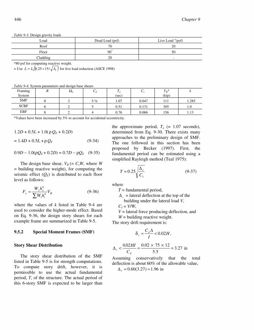
446 Chapter 9
1.2D + 0.5L + 1.0( ρ QE + 0.2D)
= 1.4D + 0.5L + ρ QE (9-34)
0.9D − 1.0(ρQE + 0.2D) = 0.7D − ρQE (9-35)
The design base shear, VB (= CsW, where W= building reactive weight), for computing theseismic effect (QE) is distributed to each floorlevel as follows:
Bkii
kxx
x VhW
hWF
∑= (9-36)
where the values of k listed in Table 9-4 areused to consider the higher-mode effect. Basedon Eq. 9-36, the design story shears for eachexample frame are summarized in Table 9-5.
9.5.2 Special Moment Frames (SMF)
Story Shear Distribution
The story shear distribution of the SMFlisted in Table 9-5 is for strength computations.To compute story drift, however, it ispermissible to use the actual fundamentalperiod, T, of the structure. The actual period ofthis 6-story SMF is expected to be larger than
the approximate period, Ta (= 1.07 seconds),determined from Eq. 9-30. There exists manyapproaches to the preliminary design of SMF.The one followed in this section has beenproposed by Becker (1997). First, thefundamental period can be estimated using asimplified Rayleigh method (Teal 1975):
1
25.0C
T r∆= (9-37)
whereT = fundamental period,
r∆ = lateral deflection at the top of the building under the lateral load V,C1 = V/W,V = lateral force producing deflection, andW = building reactive weight.
The story drift requirement is:
,HI
Cdx 02.0<
∆=δ
in27.35.5
127502.0020 =××
=<∆d
r C
HI.
Assuming conservatively that the totaldeflection is about 60% of the allowable value,
in96.1)27.3(60.0 ==∆ r
Table 9-3. Design gravity loads
Load Dead Load (psf) Live Load +(psf)
Roof 70 20
Floor 90* 50
Cladding 20 -
*80 psf for computing reactive weight.
+ Use ( )IALL /1525.00 += for live load reduction (ASCE 1998)
Table 9-4. System parameters and design base shearsFramingSystem
R Ωo Cd Ta
(sec)Cs VB*
(kip)k
SMF 8 3 5 ½ 1.07 0.047 111 1.285SCBF 6 2 5 0.51 0.131 305 1.0EBF 8 2 4 0.76 0.066 156 1.13
*Values have been increased by 5% to account for accidental eccentricity.
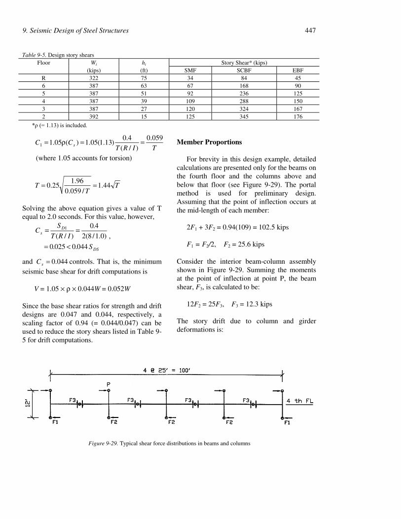
9. Seismic Design of Steel Structures 447
TIRTCC s
059.0
)/(
4.0)13.1(05.1)(05.11 ==ρ=
(where 1.05 accounts for torsion)
TT
T 44.1/059.0
96.125.0 ==
Solving the above equation gives a value of Tequal to 2.0 seconds. For this value, however,
DS
Ds
S..
.
IRT
SC
04400250
)0.1/8(2
40
)/(1
<=
==,
and 044.0=sC controls. That is, the minimumseismic base shear for drift computations is
V = 1.05 × ρ × 0.044W = 0.052W
Since the base shear ratios for strength and driftdesigns are 0.047 and 0.044, respectively, ascaling factor of 0.94 (= 0.044/0.047) can beused to reduce the story shears listed in Table 9-5 for drift computations.
Member Proportions
For brevity in this design example, detailedcalculations are presented only for the beams onthe fourth floor and the columns above andbelow that floor (see Figure 9-29). The portalmethod is used for preliminary design.Assuming that the point of inflection occurs atthe mid-length of each member:
2F1 + 3F2 = 0.94(109) = 102.5 kips
F1 = F2/2, F2 = 25.6 kips
Consider the interior beam-column assemblyshown in Figure 9-29. Summing the momentsat the point of inflection at point P, the beamshear, F3, is calculated to be:
12F2 = 25F3, F3 = 12.3 kips
The story drift due to column and girderdeformations is:
Table 9-5. Design story shearsFloor Wi hi Story Shear* (kips)
(kips) (ft) SMF SCBF EBFR 322 75 34 84 456 387 63 67 168 905 387 51 92 236 1254 387 39 109 288 1503 387 27 120 324 1672 392 15 125 345 176
*ρ (= 1.13) is included.
Figure 9-29. Typical shear force distributions in beams and columns

448 Chapter 9
gcgc EI
LhF
EI
hF
1212
22
32 +=∆+∆=∆ (9-38)
where∆ = story drift,∆ c = drift produced by column deformation,∆ g = drift produced by beam deformations,F2 = column shear,h = story height,L = beam length between points of inflection,Ic = moment of inertia of column, andIg = moment of inertia of beam.
Eq. 9-38 uses centerline dimensions andignores the shear and axial deformations of thebeams and column. In equating Eq. 9-38 to theallowable drift, it is assumed that the panel zonedeformation will contribute 15% to the storydrift; the actual contribution of the panel zonedeformation will be verified later.
in45.00031.0
,02.0)85.0(C
=≤∆
≤∆
=δ
h
hId
x
45.012
22 ≤
+
gc I
L
I
h
E
hF(9-39)
The above relationship dictates the stiffnessrequired for both the beams and columns inorder to meet the story drift requirement. Bysetting III c == as a first attempt, Eq. 9-39gives a required I = 1532 in4. Using A992 steelfor both the columns and the beams, it ispossible to select W14 132× columns( =cI 1530 in4) and W24× 62 beams( =gI 1532 in4).
In addition to satisfying the story driftrequirements, the strength of the columns andbeams also need to be checked for the forcesproduced by the normal seismic loadcombinations (Eqs. 9-34 and 9-35). However,beam and column sizes of this 6-story SMF aregenerally governed by the story drift andstrong-column weak-girder requirements.Therefore, the strength evaluations of thesemembers are not presented here.
A formal check of the strong column-weakbeam requirement will be performed later. A
quick check of this requirement for the flexuralstrength of both the beams and columns isworthwhile before the moment connections aredesigned. It is assumed that the column axialstress ( gu AP / ) is equal to 0.15Fy. Beams are
designed using the reduced beam sectionstrategy in this example. Assuming that (1) thereduced beam plastic sectional modulus (ZRBS)is 70% of the beam plastic sectional modulus(ZBM), and (2) the moment gradient (Mv) fromthe plastic hinge location to the columncenterline is 15% of the design plastic momentat the plastic hinge location:
)85.0( 2)]([2 c*
yCguypc F/AP FZM Ζ≈−=∑
)1.1(15.0,7.0 yRBSyvBMRBS FZRMZ ≈≈Ζ
]11[2 vyRBSy*pb M F ΖR.M +=∑
( )15.11.12 ×≈ yRBSy F ΖR
yBM
yBM
FZ
FZ
)97.0(2
)15.17.01.11.1(2
=×××≈
To satisfy Eq. 9-14:
0.1)97.0(2
)85.0(2*
*
≥ΖΖ
=∑
∑
BM
C
b
pc
M
M
15.1≥ΖΖ
BM
C
For the beam and column sizes selected:
15.153.1153
234 ≥==BM
C
Z
Z(OK)
Both W14×132 and W24×62 satisfy the psλrequirements given in Table 9-2. Since the RBSis to be used, additional check of the beam webcompactness is required:
1.59418
1.50 =<=yw Ft
h(OK)
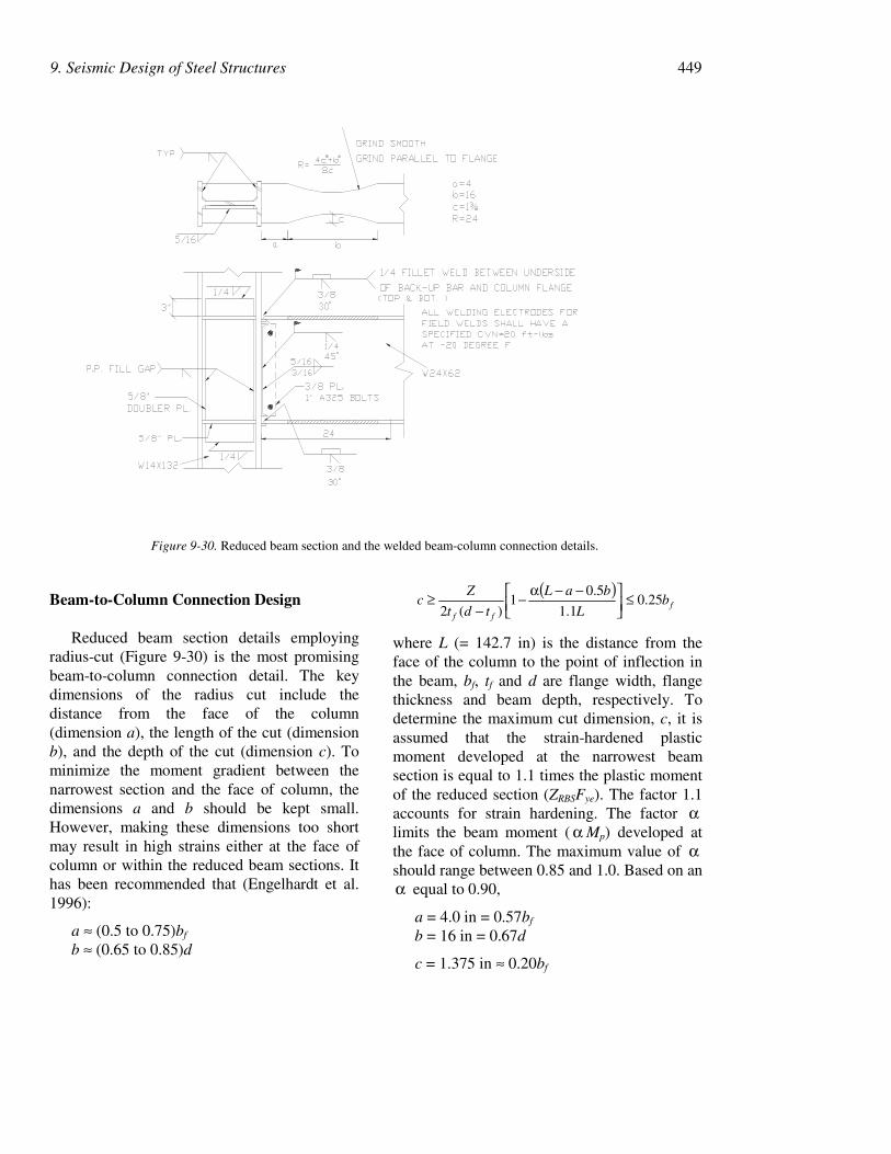
9. Seismic Design of Steel Structures 449
Beam-to-Column Connection Design
Reduced beam section details employingradius-cut (Figure 9-30) is the most promisingbeam-to-column connection detail. The keydimensions of the radius cut include thedistance from the face of the column(dimension a), the length of the cut (dimensionb), and the depth of the cut (dimension c). Tominimize the moment gradient between thenarrowest section and the face of column, thedimensions a and b should be kept small.However, making these dimensions too shortmay result in high strains either at the face ofcolumn or within the reduced beam sections. Ithas been recommended that (Engelhardt et al.1996):
a ≈ (0.5 to 0.75)bf
b ≈ (0.65 to 0.85)d
( )f
ff
bL
baL
tdt
Zc 25.0
1.1
5.01
)(2≤
−−α−
−≥
where L (= 142.7 in) is the distance from theface of the column to the point of inflection inthe beam, bf, tf and d are flange width, flangethickness and beam depth, respectively. Todetermine the maximum cut dimension, c, it isassumed that the strain-hardened plasticmoment developed at the narrowest beamsection is equal to 1.1 times the plastic momentof the reduced section (ZRBSFye). The factor 1.1accounts for strain hardening. The factor αlimits the beam moment ( α Mp) developed atthe face of column. The maximum value of αshould range between 0.85 and 1.0. Based on anα equal to 0.90,
a = 4.0 in = 0.57bf
b = 16 in = 0.67d
c = 1.375 in ≈ 0.20bf
Figure 9-30. Reduced beam section and the welded beam-column connection details.
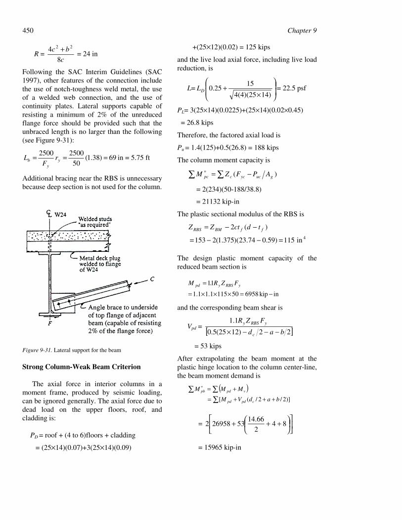
450 Chapter 9
R = c
bc
8
4 22 + = 24 in
Following the SAC Interim Guidelines (SAC1997), other features of the connection includethe use of notch-toughness weld metal, the useof a welded web connection, and the use ofcontinuity plates. Lateral supports capable ofresisting a minimum of 2% of the unreducedflange force should be provided such that theunbraced length is no larger than the following(see Figure 9-31):
69)38.1(50
25002500 === yy
b rF
L in = 5.75 ft
Additional bracing near the RBS is unnecessarybecause deep section is not used for the column.
Figure 9-31. Lateral support for the beam
Strong Column-Weak Beam Criterion
The axial force in interior columns in amoment frame, produced by seismic loading,can be ignored generally. The axial force due todead load on the upper floors, roof, andcladding is:
PD = roof + (4 to 6)floors + cladding
= (25×14)(0.07)+3(25×14)(0.09)
+(25×12)(0.02) = 125 kips
and the live load axial force, including live loadreduction, is
L=
×+
14)4(4)(25
1525.0DL = 22.5 psf
PL= 3(25×14)(0.0225)+(25×14)(0.02×0.45)
= 26.8 kips
Therefore, the factored axial load is
Pu = 1.4(125)+0.5(26.8) = 188 kips
The column moment capacity is
∑ ∑ −=∗ )( gucyccpc APFZM
= 2(234)(50-188/38.8)
= 21132 kip-in
The plastic sectional modulus of the RBS is
4in115)59.074.23)(375.1(2153
)(2
=−−=
−−= ffBMRBS tdctZZ
The design plastic moment capacity of thereduced beam section is
inkip6958501151.11.1
11
−=×××=
= yRBSypd FZR.M
and the corresponding beam shear is
Vpd = [ ]2212)(255.0
1.1
bad
FZR
c
yRBSy
−−−×
= 53 kips
After extrapolating the beam moment at theplastic hinge location to the column center-line,the beam moment demand is
( ))]2/2/([ badVM
MMM
cpdpd
vpdpb
+++=
+=
∑∑ ∑∗
=
+++ 84
2
66.1453269582
= 15965 kip-in
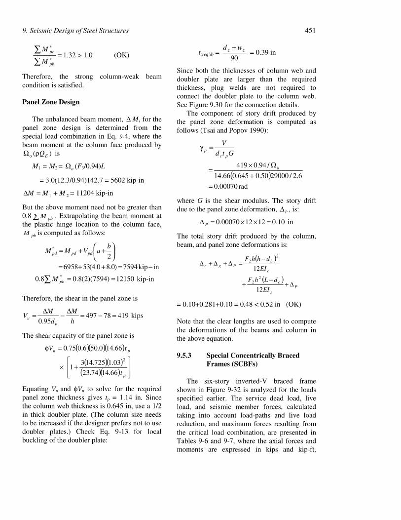
9. Seismic Design of Steel Structures 451
=∑∑
∗
∗
pb
pc
M
M1.32 > 1.0 (OK)
Therefore, the strong column-weak beamcondition is satisfied.
Panel Zone Design
The unbalanced beam moment, ∆ M, for thepanel zone design is determined from thespecial load combination in Eq. 9-4, where thebeam moment at the column face produced by
)(o EQρΩ is
M1 = M2 = oΩ (F3/0.94)L
= 3.0(12.3/0.94)142.7 = 5602 kip-in
21 MMM +=∆ = 11204 kip-in
But the above moment need not be greater than0.8 ∑ pbM . Extrapolating the beam moment atthe plastic hinge location to the column face,
pbM is computed as follows:
inkip7594)0.80.4(536958
2*
−=++=
++= baVMM pdpdpd
12150)7594)(2(8.08.0 * ==∑ pbM kip-in
Therefore, the shear in the panel zone is
4197849795.0
=−=∆−∆=h
M
d
MV
bu kips
The shear capacity of the panel zone is
( )( )( )( )( )
( )( )
+×
=φ
p
pn
t
tV
66.1474.23
03.1725.1431
66.140.506.075.0
2
Equating Vu and φVn to solve for the requiredpanel zone thickness gives tp = 1.14 in. Sincethe column web thickness is 0.645 in, use a 1/2in thick doubler plate. (The column size needsto be increased if the designer prefers not to usedoubler plates.) Check Eq. 9-13 for localbuckling of the doubler plate:
t(req’d) = 90
zz wd + = 0.39 in
Since both the thicknesses of column web anddoubler plate are larger than the requiredthickness, plug welds are not required toconnect the doubler plate to the column web.See Figure 9.30 for the connection details.
The component of story drift produced bythe panel zone deformation is computed asfollows (Tsai and Popov 1990):
( )rad00070.0
6.2/2900050.0645.066.14
/94.0419
=+
Ω×=
=γ
o
pcp Gtd
V
where G is the shear modulus. The story driftdue to the panel zone deformation, P∆ , is:
10.0121200070.0 =××=∆ P in
The total story drift produced by the column,beam, and panel zone deformations is:
( )
( )P
g
c
c
bPgc
EI
dLhF
EI
dhhF
∆+−
+
−=∆+∆+∆
12
122
2
22
= 0.10+0.281+0.10 = 0.48 < 0.52 in (OK)
Note that the clear lengths are used to computethe deformations of the beams and column inthe above equation.
9.5.3 Special Concentrically BracedFrames (SCBFs)
The six-story inverted-V braced frameshown in Figure 9-32 is analyzed for the loadsspecified earlier. The service dead load, liveload, and seismic member forces, calculatedtaking into account load-paths and live loadreduction, and maximum forces resulting fromthe critical load combination, are presented inTables 9-6 and 9-7, where the axial forces andmoments are expressed in kips and kip-ft,
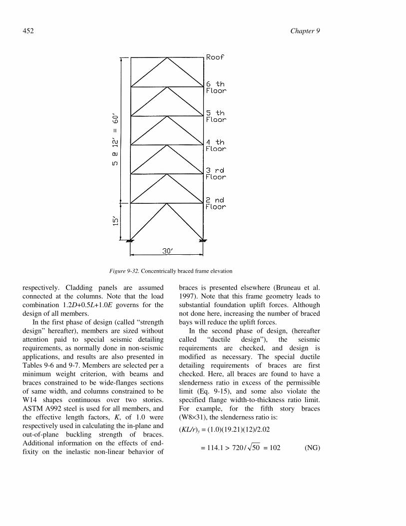
452 Chapter 9
respectively. Cladding panels are assumedconnected at the columns. Note that the loadcombination 1.2D+0.5L+1.0E governs for thedesign of all members.
In the first phase of design (called “strengthdesign” hereafter), members are sized withoutattention paid to special seismic detailingrequirements, as normally done in non-seismicapplications, and results are also presented inTables 9-6 and 9-7. Members are selected per aminimum weight criterion, with beams andbraces constrained to be wide-flanges sectionsof same width, and columns constrained to beW14 shapes continuous over two stories.ASTM A992 steel is used for all members, andthe effective length factors, K, of 1.0 wererespectively used in calculating the in-plane andout-of-plane buckling strength of braces.Additional information on the effects of end-fixity on the inelastic non-linear behavior of
braces is presented elsewhere (Bruneau et al.1997). Note that this frame geometry leads tosubstantial foundation uplift forces. Althoughnot done here, increasing the number of bracedbays will reduce the uplift forces.
In the second phase of design, (hereaftercalled “ductile design”), the seismicrequirements are checked, and design ismodified as necessary. The special ductiledetailing requirements of braces are firstchecked. Here, all braces are found to have aslenderness ratio in excess of the permissiblelimit (Eq. 9-15), and some also violate thespecified flange width-to-thickness ratio limit.For example, for the fifth story braces(W8×31), the slenderness ratio is:
(KL/r)y = (1.0)(19.21)(12)/2.02
= 114.1 > 50/720 = 102 (NG)
Figure 9-32. Concentrically braced frame elevation
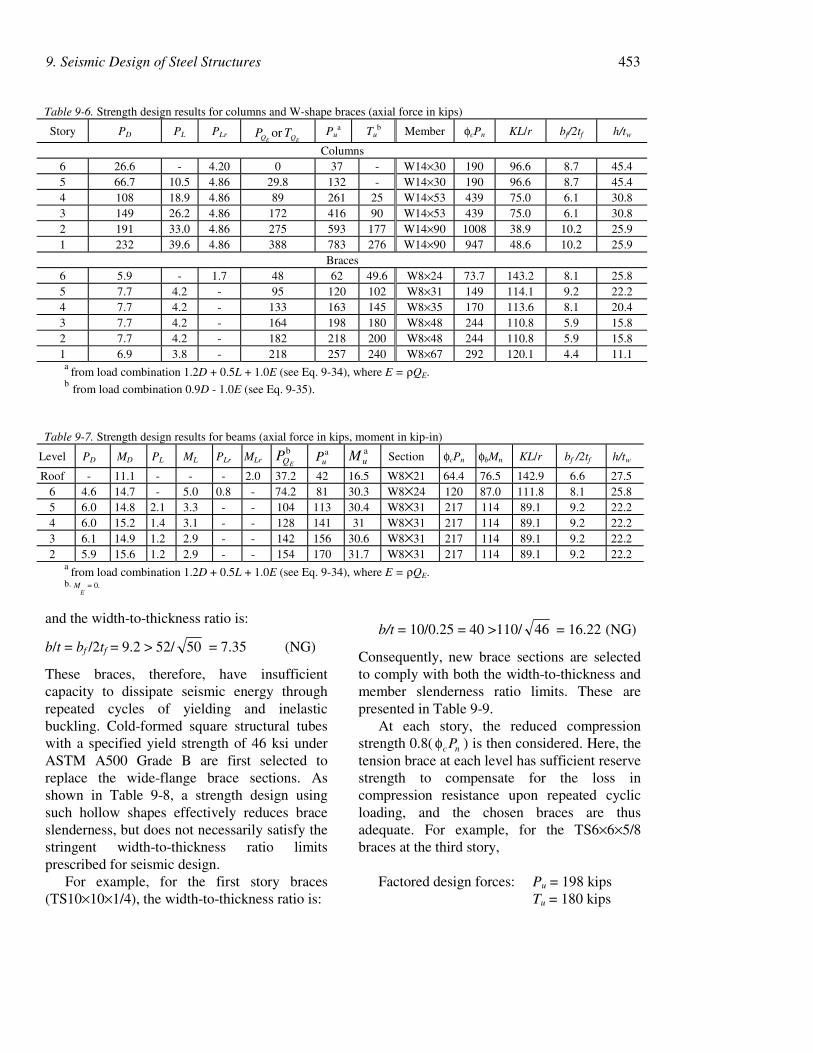
9. Seismic Design of Steel Structures 453
and the width-to-thickness ratio is:
b/t = bf /2tf = 9.2 > 52/ 50 = 7.35 (NG)
These braces, therefore, have insufficientcapacity to dissipate seismic energy throughrepeated cycles of yielding and inelasticbuckling. Cold-formed square structural tubeswith a specified yield strength of 46 ksi underASTM A500 Grade B are first selected toreplace the wide-flange brace sections. Asshown in Table 9-8, a strength design usingsuch hollow shapes effectively reduces braceslenderness, but does not necessarily satisfy thestringent width-to-thickness ratio limitsprescribed for seismic design.
For example, for the first story braces(TS10×10×1/4), the width-to-thickness ratio is:
b/t = 10/0.25 = 40 >110/ 46 = 16.22 (NG)
Consequently, new brace sections are selectedto comply with both the width-to-thickness andmember slenderness ratio limits. These arepresented in Table 9-9.
At each story, the reduced compressionstrength 0.8( ncPφ ) is then considered. Here, thetension brace at each level has sufficient reservestrength to compensate for the loss incompression resistance upon repeated cyclicloading, and the chosen braces are thusadequate. For example, for the TS6×6×5/8braces at the third story,
Factored design forces: Pu = 198 kipsTu = 180 kips
Table 9-6. Strength design results for columns and W-shape braces (axial force in kips)
Story PD PL PLrEE QQ TP or Pu
a Tub Member φcPn KL/r bf/2tf h/tw
Columns6 26.6 - 4.20 0 37 - W14×30 190 96.6 8.7 45.45 66.7 10.5 4.86 29.8 132 - W14×30 190 96.6 8.7 45.44 108 18.9 4.86 89 261 25 W14×53 439 75.0 6.1 30.83 149 26.2 4.86 172 416 90 W14×53 439 75.0 6.1 30.82 191 33.0 4.86 275 593 177 W14×90 1008 38.9 10.2 25.91 232 39.6 4.86 388 783 276 W14×90 947 48.6 10.2 25.9
Braces6 5.9 - 1.7 48 62 49.6 W8×24 73.7 143.2 8.1 25.85 7.7 4.2 - 95 120 102 W8×31 149 114.1 9.2 22.24 7.7 4.2 - 133 163 145 W8×35 170 113.6 8.1 20.43 7.7 4.2 - 164 198 180 W8×48 244 110.8 5.9 15.82 7.7 4.2 - 182 218 200 W8×48 244 110.8 5.9 15.81 6.9 3.8 - 218 257 240 W8×67 292 120.1 4.4 11.1a
from load combination 1.2D + 0.5L + 1.0E (see Eq. 9-34), where E = ρQE.b from load combination 0.9D - 1.0E (see Eq. 9-35).
Table 9-7. Strength design results for beams (axial force in kips, moment in kip-in)
Level PD MD PL ML PLr MLrb
EQP auP a
uM Section φcPn φbMn KL/r bf /2tf h/tw
Roof - 11.1 - - - 2.0 37.2 42 16.5 W8×21 64.4 76.5 142.9 6.6 27.56 4.6 14.7 - 5.0 0.8 - 74.2 81 30.3 W8×24 120 87.0 111.8 8.1 25.85 6.0 14.8 2.1 3.3 - - 104 113 30.4 W8×31 217 114 89.1 9.2 22.24 6.0 15.2 1.4 3.1 - - 128 141 31 W8×31 217 114 89.1 9.2 22.23 6.1 14.9 1.2 2.9 - - 142 156 30.6 W8×31 217 114 89.1 9.2 22.22 5.9 15.6 1.2 2.9 - - 154 170 31.7 W8×31 217 114 89.1 9.2 22.2
a from load combination 1.2D + 0.5L + 1.0E (see Eq. 9-34), where E = ρQE.
b. ME = 0.
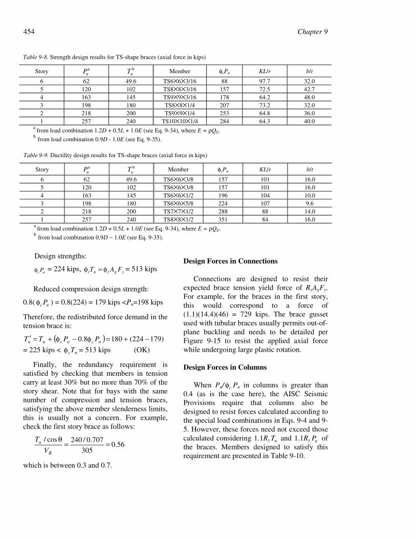
454 Chapter 9
Design strengths:
ncPφ = 224 kips, ygtnt FAT φ=φ = 513 kips
Reduced compression design strength:
0.8( ncPφ ) = 0.8(224) = 179 kips <Pu=198 kips
Therefore, the redistributed force demand in thetension brace is:
( ) )179224(1808.0 −+=φ−φ+=′ ncncuu PPTT
= 225 kips < ncTφ = 513 kips (OK)
Finally, the redundancy requirement issatisfied by checking that members in tensioncarry at least 30% but no more than 70% of thestory shear. Note that for bays with the samenumber of compression and tension braces,satisfying the above member slenderness limits,this is usually not a concern. For example,check the first story brace as follows:
56.0305
707.0/240cos/==
θ
B
u
V
T
which is between 0.3 and 0.7.
Design Forces in Connections
Connections are designed to resist theirexpected brace tension yield force of RyAgFy.For example, for the braces in the first story,this would correspond to a force of(1.1)(14.4)(46) = 729 kips. The brace gussetused with tubular braces usually permits out-of-plane buckling and needs to be detailed perFigure 9-15 to resist the applied axial forcewhile undergoing large plastic rotation.
Design Forces in Columns
When Pu/ cφ Pn in columns is greater than0.4 (as is the case here), the AISC SeismicProvisions require that columns also bedesigned to resist forces calculated according tothe special load combinations in Eqs. 9-4 and 9-5. However, these forces need not exceed thosecalculated considering 1.1Ry nT and 1.1Ry nP ofthe braces. Members designed to satisfy thisrequirement are presented in Table 9-10.
Table 9-8. Strength design results for TS-shape braces (axial force in kips)
Story auP b
uT Member φcPn KL/r b/t
6 62 49.6 TS6×6×3/16 88 97.7 32.05 120 102 TS8×8×3/16 157 72.5 42.74 163 145 TS9×9×3/16 178 64.2 48.03 198 180 TS8×8×1/4 207 73.2 32.02 218 200 TS9×9×1/4 253 64.8 36.01 257 240 TS10×10×1/4 284 64.3 40.0
a from load combination 1.2D + 0.5L + 1.0E (see Eq. 9-34), where E = ρQE.
b from load combination 0.9D - 1.0E (see Eq. 9-35).
Table 9-9. Ductility design results for TS-shape braces (axial force in kips)
Story auP b
uT Member φcPn KL/r b/t
6 62 49.6 TS6×6×3/8 157 101 16.05 120 102 TS6×6×3/8 157 101 16.04 163 145 TS6×6×1/2 196 104 10.03 198 180 TS6×6×5/8 224 107 9.62 218 200 TS7×7×1/2 288 88 14.01 257 240 TS8×8×1/2 351 84 16.0
a from load combination 1.2D + 0.5L + 1.0E (see Eq. 9-34), where E = ρQE.
b from load combination 0.9D − 1.0E (see Eq. 9-35).
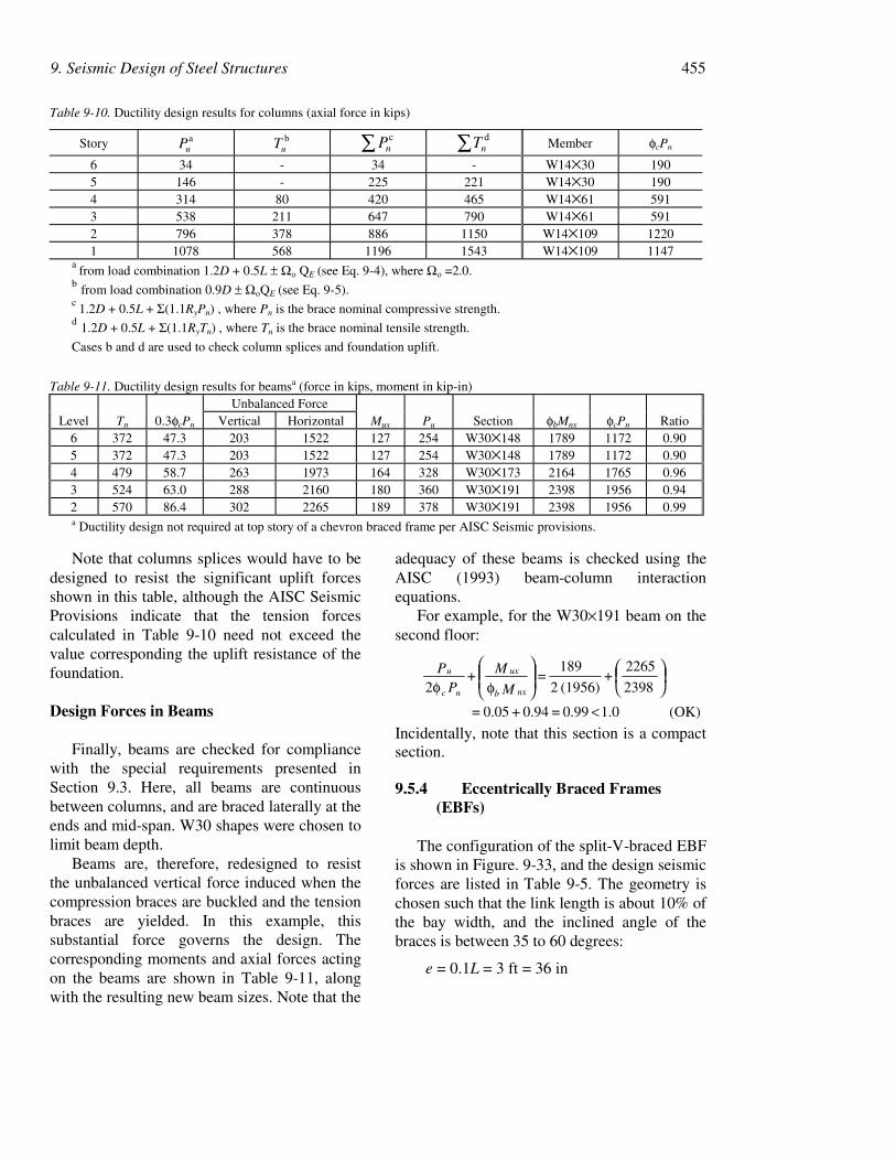
9. Seismic Design of Steel Structures 455
Note that columns splices would have to bedesigned to resist the significant uplift forcesshown in this table, although the AISC SeismicProvisions indicate that the tension forcescalculated in Table 9-10 need not exceed thevalue corresponding the uplift resistance of thefoundation.
Design Forces in Beams
Finally, beams are checked for compliancewith the special requirements presented inSection 9.3. Here, all beams are continuousbetween columns, and are braced laterally at theends and mid-span. W30 shapes were chosen tolimit beam depth.
Beams are, therefore, redesigned to resistthe unbalanced vertical force induced when thecompression braces are buckled and the tensionbraces are yielded. In this example, thissubstantial force governs the design. Thecorresponding moments and axial forces actingon the beams are shown in Table 9-11, alongwith the resulting new beam sizes. Note that the
adequacy of these beams is checked using theAISC (1993) beam-column interactionequations.
For example, for the W30×191 beam on thesecond floor:
OK)(1.0 0.99 = 0.94 + 0.05 =
2398
2265 +
(1956) 2
189 = +
2
<
φφ M
MP
P
nxb
ux
nc
u
Incidentally, note that this section is a compactsection.
9.5.4 Eccentrically Braced Frames(EBFs)
The configuration of the split-V-braced EBFis shown in Figure. 9-33, and the design seismicforces are listed in Table 9-5. The geometry ischosen such that the link length is about 10% ofthe bay width, and the inclined angle of thebraces is between 35 to 60 degrees:
e = 0.1L = 3 ft = 36 in
Table 9-10. Ductility design results for columns (axial force in kips)
Story auP b
uT ∑ cnP ∑ d
nT Member φcPn
6 34 - 34 - W14×30 1905 146 - 225 221 W14×30 1904 314 80 420 465 W14×61 5913 538 211 647 790 W14×61 5912 796 378 886 1150 W14×109 12201 1078 568 1196 1543 W14×109 1147
a from load combination 1.2D + 0.5L ± Ωo QE (see Eq. 9-4), where Ωo =2.0.
b from load combination 0.9D ± ΩoQE (see Eq. 9-5).c
1.2D + 0.5L + Σ(1.1RyPn) , where Pn is the brace nominal compressive strength.d 1.2D + 0.5L + Σ(1.1RyTn) , where Tn is the brace nominal tensile strength.
Cases b and d are used to check column splices and foundation uplift.
Table 9-11. Ductility design results for beamsa (force in kips, moment in kip-in)Unbalanced Force
Level Tn 0.3φcPn Vertical Horizontal Mux Pu Section φbMnx φcPn Ratio6 372 47.3 203 1522 127 254 W30×148 1789 1172 0.905 372 47.3 203 1522 127 254 W30×148 1789 1172 0.904 479 58.7 263 1973 164 328 W30×173 2164 1765 0.963 524 63.0 288 2160 180 360 W30×191 2398 1956 0.942 570 86.4 302 2265 189 378 W30×191 2398 1956 0.99a Ductility design not required at top story of a chevron braced frame per AISC Seismic provisions.

456 Chapter 9
°==θ − 48)5.13/15(tan 1 (first story)
°==θ − 42)5.13/12(tan 1 (other stories)
In this example, detailed design calculations areonly presented for members at the first story toillustrate the procedure. Unless indicatedotherwise, ASTM A992 steel is used.
Figure 9-33. Eccentrically braced frame elevation
Link Design
Shear links with e ≤ 1.6 Mp/Vp are used toachieve higher structural stiffness and strength.The AISC Seismic Provisions stipulate that thebeam outside the link shall be able to resist theforces generated by at least 1.1 times theexpected nominal shear strength of the link.
Assuming that the braces are rigidly connectedto the link, that the beam can resist 95% of thelink end moment, and that the beam flexuralcapacity is reduced by 30% due to the presenceof an axial force:
)2/()1.1(85.0)()7.0( eVRMR nypby ≥φ
or
1.35Mp/Vn ≥ e
For shear links, the above requirement for themaximum link length is more stringent than1.6Mp/Vp. The required strengths for the link onthe second floor are
kips1000.98)4.0(5.0)1.1(4.1
5.04.1
=++=++= ELDVu
ELDM u ++= 5.04.1)2/0.3(98)0.3(5.0)0.8(4.1 ++= 160=
kip-ft
Note that there is no axial force acting on theshear links (i.e., 0=uP kip). Illustrating thisprocedure for the shear link on the second floor:
in7.26/in36/35.1 ≥⇒≥ pppp VMVM
pnu VVV φ=φ≤= kips100
)2()50)(6.0(9.0 fw tdt −=2in70.3)2( ≥−⇒ fw tdt
( )eMVV pnu /2kips100 φ=φ≤=3in0.4036/)50)(9.0(2 ≥⇒= xx ZZ
Based on the above three requirements, select aW12×45 section for the link:
.Z x33 in0.40in764 >= (OK)
. .tdt fw22 in703in873)2( >=− (OK)
in726in927)26(0
. .ttd.
Z
V
M
wf
x
p
p >=−
= (OK)
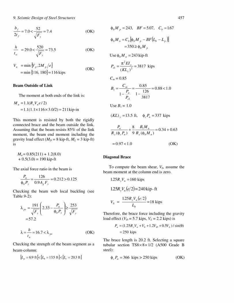
9. Seismic Design of Steel Structures 457
4.752
0.72
=<=yf
f
Ft
b(OK)
5.73520
0.29 =<=yw Ft
h(OK)
kips 116180116min
2min
==
=
,
eM,VV ppn (OK)
Beam Outside of Link
The moment at both ends of the link is:
)2/(1.1 eVRM nyu =2113.0/2)1161.1(1.1 =××= kip-in
This moment is resisted by both the rigidlyconnected brace and the beam outside the link.Assuming that the beam resists 85% of the linkmoment, the beam end moment including thegravity load effect (MD = 8 kip-ft, ML = 3 kip-ft)is
Mu = 0.85(211) + 1.2(8.0) + 0.5(3.0) = 190 kip-ft
The axial force ratio in the beam is
125.0212.090.
126 >==φ ygyb
u
FAP
P
Checking the beam web local buckling (seeTable 9-2):
2.57
25333.2
191
=
≥
φ
−=λyyb
u
y
psFP
P
F
pswt
h λ<==λ 7.16 (OK)
Checking the strength of the beam segment as a
beam-column:
[ ] [ ] [ ]ft320 ft513 ft96 .L .L .L rbp =<=<=
671 ,075 ,243 .C.BFM bpb ≈==φ
( )[ ] 350 pb
pbpbbnb
M
LLBFMCM
φ≥=
−−φ=φ
243 Use =φ nb M kip-ft
kips 3817)( 2
2
1 =π
=x
xe
KL
EIP
Cm = 0.85
0.188.0
3817
1261
85.0
11
1 <=−
=−
=
e
u
m
P
PC
B
Use B1 = 1.0
kips 337 ft,5.13)( =φ= ncy PKL
63.034.0)(9
8
)(1 +=φ
+φ nby
u
ncy
u
MR
MB
PR
P
(OK)0.197.0 <=
Diagonal Brace
To compute the beam shear, Vb, assume thebeam moment at the column end is zero.
kips160251 VR. ny =
( ) ft-kip2402251 eVR. ny =
( )kips18
2251
L
eVR. V
b
nyb ==
Therefore, the brace force including the gravityload effect (VD = 5.7 kips, VL = 2.2 kips) is
kips250
)sin(/)5.02.125.1(
=
θ+++= LDbnyu VVVVRP
The brace length is 20.2 ft. Selecting a squaretubular section TS8× 8× 1/2 (A500 Grade Bsteel):
366=φ nc P kips > 250 kips (OK)
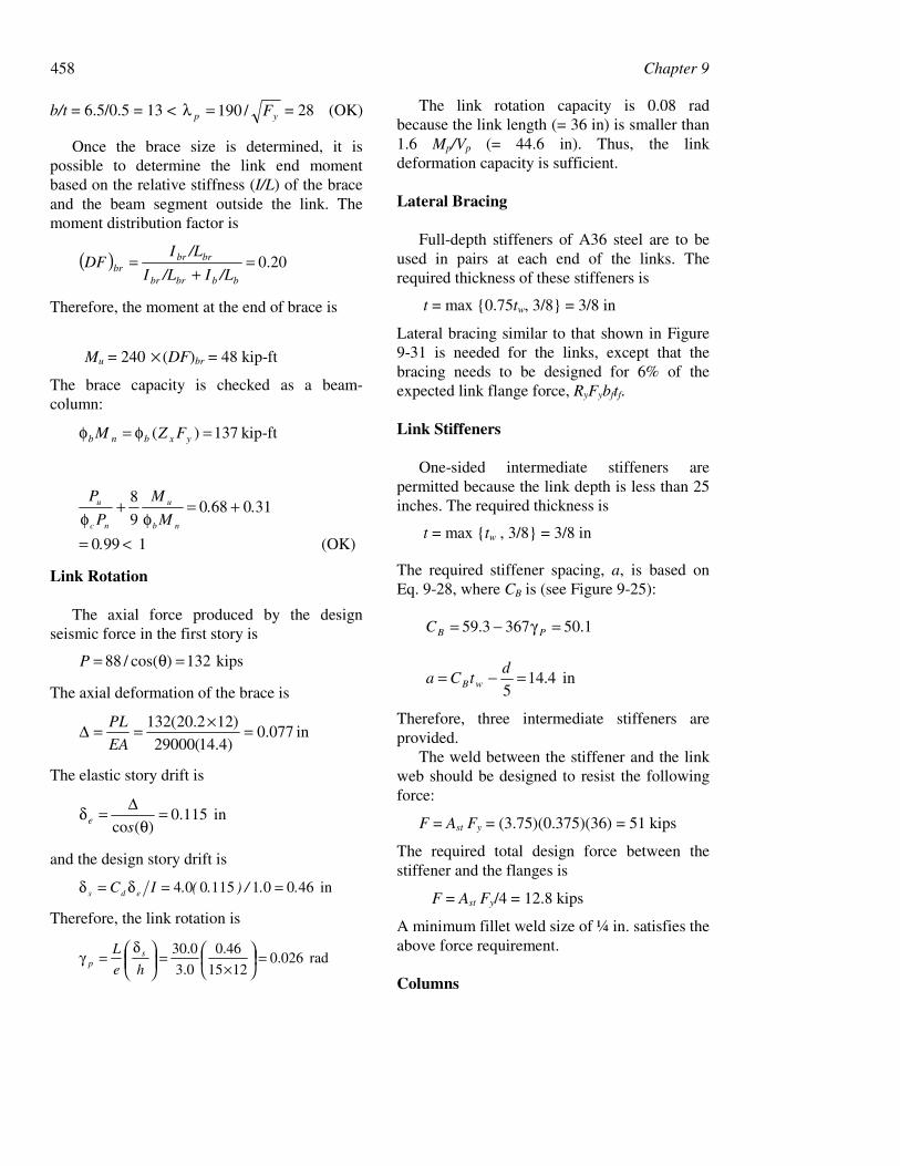
458 Chapter 9
b/t = 6.5/0.5 = 13 < yp F/190=λ = 28 (OK)
Once the brace size is determined, it ispossible to determine the link end momentbased on the relative stiffness (I/L) of the braceand the beam segment outside the link. Themoment distribution factor is
( ) 20.0=+
=bbbrbr
brbrbr /LI/LI
/LIDF
Therefore, the moment at the end of brace is
Mu = 240 × (DF)br = 48 kip-ft
The brace capacity is checked as a beam-column:
137)( =φ=φ yxbnb FZM kip-ft
(OK)1 990
3106809
8
.
..M
M
P
P
nb
u
nc
u
<=
+=φ
+φ
Link Rotation
The axial force produced by the designseismic force in the first story is
kips132)(cos/88 =θ=P
The axial deformation of the brace is
in 077.0)4.14(29000
)122.20(132 =×==∆EA
PL
The elastic story drift is
in 115.0)(co
=θ
∆=δse
and the design story drift is
in 46001115004 ../).(.IC eds ==δ=δ
Therefore, the link rotation is
rad 026.01215
46.0
0.3
0.30 =
×=
δ
=γhe
L sp
The link rotation capacity is 0.08 radbecause the link length (= 36 in) is smaller than1.6 Mp/Vp (= 44.6 in). Thus, the linkdeformation capacity is sufficient.
Lateral Bracing
Full-depth stiffeners of A36 steel are to beused in pairs at each end of the links. Therequired thickness of these stiffeners is
t = max 0.75tw, 3/8 = 3/8 in
Lateral bracing similar to that shown in Figure9-31 is needed for the links, except that thebracing needs to be designed for 6% of theexpected link flange force, RyFybftf.
Link Stiffeners
One-sided intermediate stiffeners arepermitted because the link depth is less than 25inches. The required thickness is
t = max tw , 3/8 = 3/8 in
The required stiffener spacing, a, is based onEq. 9-28, where CB is (see Figure 9-25):
1.503673.59 =γ−= PBC
in 4.145
=−= dtCa wB
Therefore, three intermediate stiffeners areprovided.
The weld between the stiffener and the linkweb should be designed to resist the followingforce:
F = Ast Fy = (3.75)(0.375)(36) = 51 kips
The required total design force between thestiffener and the flanges is
F = Ast Fy/4 = 12.8 kips
A minimum fillet weld size of ¼ in. satisfies theabove force requirement.
Columns
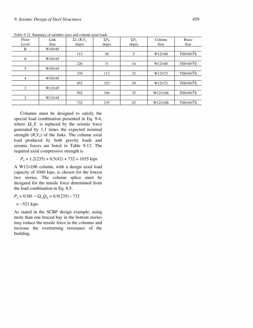
9. Seismic Design of Steel Structures 459
Columns must be designed to satisfy thespecial load combination presented in Eq. 9-4,where EoΩ is replaced by the seismic forcegenerated by 1.1 times the expected nominalstrength (RyVn) of the links. The column axialload produced by both gravity loads andseismic forces are listed in Table 9-12. Therequired axial compressive strength is
Pu = 1.2(235) + 0.5(42) + 732 = 1035 kips
A W12×106 column, with a design axial loadcapacity of 1040 kips, is chosen for the lowesttwo stories. The column splice must bedesigned for the tensile force determined fromthe load combination in Eq. 8.5:
Pu = 0.9D EQoΩ− = 0.9(235) 732−
= −521 kips
As stated in the SCBF design example, usingmore than one braced bay in the bottom storiesmay reduce the tensile force in the columns andincrease the overturning resistance of thebuilding.
Table 9-12. Summary of member sizes and column axial loadsFloor Link Σ1.1RyVn ΣPD ΣPL Column BraceLevel Size (kips) (kips) (kips) Size Size
R W10×45113 30 5 W12×40 TS8×8×½
6 W10×45226 71 14 W12×40 TS8×8×½
5 W10×45339 112 22 W12×72 TS8×8×½
4 W10×45452 153 29 W12×72 TS8×8×½
3 W12×45592 194 35 W12×106 TS8×8×½
2 W12×45732 235 42 W12×106 TS8×8×½
460 Chapter 9
REFERENCES
9-1 AIJ, Performance of Steel Buildings during the 1995Hyogoken-Nanbu Earthquake (in Japanese withEnglish summary), Architectural Inst. of Japan,Tokyo, Japan, 1995.
9-2 AISC, Load and Resistance Factor DesignSpecification for Structural Steel Buildings, AISC,Chicago, IL, 1993.
9-3 AISC, Specifications for Structural Steel Buildings,AISC, Chicago, IL, 1989.
9-4 AISC, Near the Fillet of Wide Flange Shapes andInterim Recommendations, Advisory Statement onMechanical Properties, AISC, Chicago, IL, 1997a.
9-5 AISC, Seismic Provisions for Structural SteelBuildings, with Supplement No. 1 (1999), AISC,Chicago, IL, 1992 and 1997b.
9-6 ASCE, Minimum Design Loads for Buildings andOther Structures, ASCE Standard 7-98, ASCE, NewYork, NY, 1998.
9-7 Astaneh-Asl, A., Goel, S.C., Hanson, R.D.,“Earthquake-resistant Design of Double AngleBracings,” Engrg. J., Vol. 23, No. 4, pp. 133-147,AISC, 1981.
9-8 Becker, R., “Seismic Design of Steel Buildings UsingLRFD,” in Steel Design Handbook (editor: A. R.Tamboli), McGraw-Hill, 1997.
9-9 Bruneau, M., Mahin, S.A., “Ultimate Behavior ofHeavy Steel Section Welded Splices and DesignImplications,” J. Struct. Engrg., Vol. 116, No. 8, pp.2214-2235, ASCE, 1990.
9-10 Bruneau, M., Uang, C.M, Whittaker, A., DuctileDesign of Steel Structures, McGraw Hill, New York,NY, 1997.
9-11 BSSC, NEHRP Recommended Provisions for theDevelopment of Seismic Regulations for NewBuildings, Federal Emergency Management Agency,Washington, DC, 1997.
9-12 Chen, S.J., Yeh, C.H. and Chu, J.M., “Ductile SteelBeam-Column Connections for Seismic Resistance,”J. Struct. Engrg., Vol. 122, No. 11, pp. 1292-1299.ASCE, 1996.
9-13 Chi, B. and Uang, C.M., “Seismic Retrofit Study onSteel Moment Connections for the Los AngelesDepartment of Public Works Headquarters Building,”Report No. TR-2000/14, Department of StructuralEngineering, University of California, San Diego, LaJolla, CA, 2000.
9-14 Engelhardt, M. D. and Popov, E. P., "On Design ofEccentrically Braced Frames," Earthquake Spectra,Vol. 5, No. 3, pp. 495-511, EERI, 1989.
9-15 Engelhardt, M.D. and Sabol, T., “Reinforcing ofSteel Moment Connections with Cover Plates:Benefits and Limitations,” Engrg. J., Vol. 20, Nos. 4-6, pp. 510-520, 1998.
9-16 Engelhardt, M.D., Winneburger, T., Zekany, A.J.,and Potyraj, T.J., “The Dogbone Connection: PartII,” Modern Steel Construct., Vol. 36. No. 8, pp. 46-55, AISC, 1996.
9-17 Fujimoto, M., Aoyagi, T., Ukai, K., Wada, A., and K.Saito, "Structural Characteristics of Eccentric K-Braced Frames," Trans., No. 195, pp. 39-49, AIJ,May 1972.
9-18 Gilton, C., Chi, B., and Uang, C.-M., "CyclicResponse of RBS Moment Connections: Weak-AxisConfiguration and Deep Column Effects," Report No.SSRP-2000/03, Department of StructuralEngineering, University of California, San Diego, LaJolla, CA, 2000.
9-19 Gross, J. L., Engelhardt, M. D., Uang, C.-M., Kasai,K., and N. Iwankiw, Modification of Existing WeldedSteel Moment Frame Connections for SeismicResistance, Steel Design Guide Series 12, AISC andNIST, 1998.
9-20 Hamburger, R. “More on Welded Connections,”SEAONC News, Structural Engineers Association ofNorthern California, San Francisco, CA, April, 1996.
9-21 Hjelmstad, K. D. and Popov, E. P., "Characteristicsof Eccentrically Braced Frames," J. Struct. Engrg.,Vol. 110, No. 2, pp. 340-353, ASCE, 1984.
9-22 Hjelmstad, K. D. and Popov, E. P., "Cyclic Behaviorand Design of Link Beams," J. Struct. Engrg., Vol.109, No. 10, pp. 2387-2403, ASCE, 1983.
9-23 ICBO, Uniform Building Code, Int. Conf. of BuildingOfficials, Whittier, CA, 1988.
9-24 Iwankiw, R.N. and Carter, C.J., “The Dogbone: ANew Idea to Chew On,” Modern Steel Construct.,Vol. 36. No. 4, pp. 18-23, AISC, Chicago IL, 1996.
9-25 Jokerst, M. S. and Soyer, C., "San Francisco CivicCenter Complex: Performance Based Design withPassive Dampers and Welded Steel Frames," Proc.,65th Annual Convention, pp. 119-134, SEAOC,1996.
9-26 Kasai, K. and Popov, E. P., "On Seismic Design ofEccentrically Braced Frames," Proc., 8th WorldConf. Earthquake Engrg., Vol. V, pp. 387-394, IAEE,San Francisco, 1985.
9-27 Kasai, K. and Popov, E. P., "Cyclic Web BucklingControl for Shear Link Beams," J. Struct. Engrg.,Vol. 112, No. 3, pp. 505-523, ASCE, 1986a.
9-28 Kasai, K. and Popov, E. P., "General Behavior of WFSteel Shear Link Beams," J. Struct. Engrg., Vol. 112,No. 2, pp. 362-382, ASCE, 1986b.
9-29 Krawinkler, H., Bertero, V.V., and Popov, E.P.,“Inelastic Behavior of Steel Beam-ColumnSubassemblages,” Report No. UCB/EERC-71/7,Univ. of Calif., Berkeley, Berkeley, CA, 1971.
9-30 Krawinkler, H., Bertero, V.V., and Popov, E.P.,“Shear Behavior of Steel Frame Joints,” J. Struct.Div., Vol. 101, ST11, pp. 2317-2338. ASCE, 1975.

9. Seismic Design of Steel Structures 461
9-31 Libby, J. R., "Eccentrically Braced FrameConstruction−A Case Study," Engrg. J., Vol. 18, No.4, pp. 149-153, AISC, 1981.
9-32 Malley, J. O. and Popov, E. P., "Shear Links inEccentrically Braced Frames," J. Struct. Engrg., Vol.110, No. 9, pp. 2275-2295, ASCE, 1984.
9-33 Manheim, D. N. and Popov, E. P., "Plastic ShearHinges in Steel Frames," J. Struct. Engrg., Vol. 109,No. 10, pp. 2404-2419, ASCE, 1983.
9-34 Merovich, A., Nicoletti, J. P., and Hartle, E.,"Eccentric Bracing in Tall Buildings," J. Struct. Div.,Vol. 108, No. ST9, pp. 2066-2080, ASCE, 1982.
9-35 Nakashima, M. And Wakabayashi, M., “Analysis andDesign of Steel Braces and Braced Frames,” inStability and Ductility of Steel Structures underCyclic Loading, pp. 309-322, CRC Press, 1992.
9-36 Noel, S. and Uang, C.-M., “Cyclic Testing of SteelMoment Connections for the San Francisco CivicCenter Complex,” Report No. TR-96/07, Univ. ofCalifornia, San Diego, La Jolla, CA, 1996.
9-37 Plumier, A., “New Idea for Safe Structures inSeismic Zones,” Proc., Symposium of MixedStructures Including New Materials, pp. 431-436,IABSE, Brussels, Belgium, 1990.
9-38 Redwood, R.G., and Channagiri, V.S., “Earthquake-Resistant Design of Concentrically Braced SteelFrames,” Canadian J. Civil Engrg., Vol. 18, No. 5,pp. 839-850, 1991.
9-39 Ricles, J. M. and Popov, E. P., "Composite Action inEccentrically Braced Frames," J. Struct. Engrg., Vol.115, No. 8, pp. 2046-2065, ASCE, 1989.
9-40 Roeder, C. W. and Popov, E. P., "EccentricallyBraced Steel Frames For Earthquakes," J. Struct.Div., Vol. 104, No. ST3, pp. 391-411, ASCE, 1978.
9-41 Roeder, C. W., Foutch, D. A., and Goel, S. C.,"Seismic Testing of Full-Scale Steel Building−PartII," J. Struct. Engrg., Vol. 113, No. 11, pp. 2130-2145, ASCE, 1987.
9-42 SAC, “Interim Guidelines: Evaluation, Repair,Modification, and Design of Welded Steel MomentFrame Structures,” Report FEMA No. 267/SAC-95-02, SAC Joint Venture, Sacramento, CA, 1995.
9-43 SAC, “Interim Guidelines Advisory No. 1,Supplement to FEMA 267,” Report No. FEMA267A/SAC-96-03, SAC Joint Venture, Sacramento,CA, 1997.
9-44 SAC, “Technical Report: Experimental Investigationsof Beam-Column Subassemblages, Parts 1 and 2,”Report No. SAC-96-01, SAC Joint Venture,Sacramento, CA, 1996.
9-45 SAC, “Recommended Seismic Design Criteria forNew Moment-Resisting Steel Frame Structures,”Report No. FEMA 350, SAC Joint Venture,Sacramento, CA, 2000.
9-46 Shibata, M., Nakamura T., Yoshida, N., Morino, S.,Nonaka, T., and Wakabayashi, M., “Elastic-PlasticBehavior of Steel Braces under Repeated Axial
Loading,” Proc., 5th World Conf. Earthquake Engrg.,Vol. 1, pp. 845-848, IAEE, Rome, Italy, 1973.
9-47 SSPC, Statistical Analysis of Tensile Data for Wide-Flange Structural Shapes, Chaparral Steel Co.,Midlothian, TX, 1994.
9-48 Tanabashi, R., Naneta, K., and Ishida, T., "On theRigidity and Ductility of Steel Bracing Assemblage,"Proc., 5th World Conf. Earthquake Engrg., Vol. 1,pp. 834-840, IAEE, Rome, Italy, 1974.
9-49 Teal, E. J., "Seismic Drift Control Criteria," Engrg.J., Vol. 12, No. 2, pp. 56-67, AISC, 1975.
9-50 Teal, E., Practical Design of Eccentric BracedFrames to Resist Seismic Forces, Struct. Steel Res.Council, CA, 1979.
9-51 Tremblay, R., Bruneau, M., Nakashima, M., Prion,H.G.L., Filiatrault, M., DeVall, R., “Seismic Designof Steel Buildings: Lessons from the 1995 Hyogo-ken Nanbu Earthquake”, Canadian J. Civil Engrg.,Vol. 23, No. 3, pp. 757-770, 1996.
9-52 Tremblay, R., Timler, P., Bruneau, M., Filiatrault, A.,“Performance of Steel Structures during the January17, 1994, Northridge Earthquake,” Canadian J. CivilEngrg., Vol. 22, No. 2, pp. 338-360, 1995.
9-53 Tsai, K.-C., and Popov, E.P., “Seismic Panel ZoneDesign Effects on Elastic Story Drift of SteelFrames,” J. Struct. Engrg., Vol. 116, No. 12, pp.3285-3301, ASCE, 1990.
9-54 Tsai, K.-C., and Popov, E.P., “Steel Beam-ColumnJoints in Seismic Moment-Resisting Frames,” ReportNo. UCB/EERC-88/19, Univ. of Calif., Berkeley,1988.
9-55 Yu, Q.S., Uang, C.M., and Gross, J., “SeismicRehabilitation Design of Steel Moment Connectionwith Welded Haunch,” Journal of StructuralEngineering, Vol. 126, No. 1, pp. 69-78, ASCE,2000.
9-56 Uang, C.-M. "Establishing R (or Rw) and Cd Factorsfor Building Seismic Provisions," J. Struct. Engrg.,Vol. 117, No. 1, pp. 19-28, ASCE, 1991.
9-57 Uang, C.-M. and Noel, S., “Cyclic Testing of Strong-and Weak-Axis Steel Moment Connection withReduced Beam Flanges,” Report No. TR-96/01, Univ.of Calif., San Diego, CA, 1996.
9-58 Uang, C.-M and Fan, C.C, “Cyclic Stability ofMoment Connections with Reduced Beam Section,”Report No. SSRP-99/21, Department of StructuralEngineering, University of California, San Diego, LaJolla, CA, 1999.
9-59 Whittaker, A. S., Uang, C.-M., and Bertero, V. V.,"Seismic Testing of Eccentrically Braced Dual SteelFrames," Earthquake Spectra, Vol. 5, No. 2, pp. 429-449, EERI, 1989.
9-60 Whittaker, A.S. and Gilani, A., “Cyclic Testing ofSteel Beam-Column Connections,” Report No.EERC-STI/96-04, Univ. of Calif., Berkeley, 1996.
9-61 Whittaker, A.S., Bertero V.V., and Gilani, A.S.“Evaluation of Pre-Northridge Steel Moment-

462 Chapter 9
Resisting Joints.” Struct. Design of Tall Buildings.Vol. 7, No. 4, pp. 263-283, 1998.
9-62 Yang, M.-S., "Shaking Table Studies of anEccentrically Braced Steel Structure," Proc., 8thWorld Conf. Earthquake Engrg., Vol. IV, pp. 257-264, IAEE, San Francisco, CA, 1985.
9-63 Zekioglu, A., Mozaffarian, H., Chang, K.L., Uang,C.-M., and Noel, S., “Designing after Northridge”,Modern Steel Construct., Vol. 37. No. 3, pp. 36-42,AISC, 1997.


![Seismic collapse performance of special moment steel …earthquake.hanyang.ac.kr/journal/2017/[2017]Han et al-Seismic... · Seismic collapse performance of special moment steel frames](https://img.dokumen.tips/doc/110x75/5b8364d47f8b9adc698cfc15/seismic-collapse-performance-of-special-moment-steel-2017han-et-al-seismic.jpg)