Embed Size (px)
Citation preview

Security Printing of Covert Codes using
NIR-to-NIR Upconversion Inks
Prepared by:
Cecilia Douma
Faculty Advisors:
Dr. Stanley May
REU Site Leader, Department of Chemistry
Dr. Alfred Boysen
Professor, Department of Humanities
Program Information:
National Science Foundation
NSF Grant EEC-1263343
Research Experience for Undergraduates
Summer 2014
University of South Dakota

2
TABLE OF CONTENTS
Abstract ..........................................................................................................................................3
Introduction ..................................................................................................................................4
Broader Impact ............................................................................................................................6
Procedure .......................................................................................................................................6
Visualization of NIR Emission ............................................................................................6
Synthesis and Characterization of NaYF4:Yb/Tm ...............................................................8
NIR Emission through Opaque Ink......................................................................................9
Results and Discussion ............................................................................................................10
Visualization of NIR Emission ..........................................................................................10
Synthesis and Characterization of NaYF4:Yb/Tm .............................................................12
NIR Emission through Opaque Ink....................................................................................14
Conclusion ..................................................................................................................................17
References ...................................................................................................................................17
Acknowledgments.....................................................................................................................18

3
Abstract
Upconversion nanoparticles (UCNPs) of β-phase NaYF4 doped with Yb and Tm exhibit
‘upconverted’ near-infrared 800 nm emission when excited with 980 nm light. This so-called
NIR-to-NIR luminescence is of interest for security printing because both the NIR excitation and
the upconverted NIR emission can pass through selective protective opaque ink or dye layers and
cannot be detected by the naked eye. The intensity of the emission is affected by the
concentration of Yb and Tm in the nanoparticles. In this report, we optimize dopant
concentrations for the NIR emission. Working with collaborators at SDSM&T, we develop inks
that can be used to print NIR-to-NIR upconversion images. We then demonstrate that these
images can still be read using CCD cameras even when they are covered with visibly opaque
protective coatings.

4
1. Introduction
Upconversion is the process by which low-energy photons are sequentially absorbed,
exciting electrons first from ground state to an excited state and then from that excited state to an
even higher state. When the electron returns to a lower energy state, a high-energy photon is
emitted.1 Upconversion nanoparticles (UCNPs) have been a focus of recent research because of
their wide range of potential applications, including bioimaging, lasers, lighting, and security
printing.2 Of these UCNPs, lanthanide-doped β-phase NaYF4 is recognized for its exceptionally
efficient near-infrared (NIR) to visible upconversion. The concentrations and combinations of
lanthanide dopants influence both the wavelength and the intensity of the emission.3,4,5 For
example, NaYF4 doped with Yb and Tm is known for its visible blue (440-500 nm) emission.
However, the system also emits 800 nm light. This NIR emission is much more intense than the
blue, but it is not visible to the naked eye (Figure 1).
Figure 1: Upconversion emission spectra of NaYF4:Yb/Tm (25/0.3 mol %) excited by a 980 nm laser at a
variety of power densities.
800
600
400
200
0
Inte
ns
ity
(d
N/d
t/d
)
1000900800700600500400
Wavelength (nm)
Power Density
10.1 W/cm2
9.2 W/cm2
7.7 W/cm2
6.1 W/cm2
4.6 W/cm2
3.2 W/cm2
1.9 W/cm2
0.7 W/cm2
980 nm
excitation
800 nm
emission
Blue
emission

5
UCNPs have been explored as a method to improve security printing, since inks made
with UCNPs are invisible unless excited at specific wavelengths and are more challenging to
formulate than traditional security inks. The emission color of the inks can be manipulated, and
the combination of color, luminescence, and image created by UCNP security inks is very
difficult to replicate.6 An additional level of protection could be added if the security ink code
some transmit NIR light. This means that UCNPs could be excited even when they are covered
by black ink. The 800 nm emission of NaYF4:Yb/Tm could also pass through the ink, although
the blue emission would be blocked. The NIR emission would not be visible to the naked eye
but could be visualized using a digital camera or smart phone. Therefore, an UCNP image
printed beneath a layer of ink would be undetectable without appropriate equipment and would
be resistant to tampering efforts by counterfeiters (Figure 2).
Figure 2: Diagram of NIR-to-NIR security printing concept.
Paper
UCNPs
Opaque Ink
980 nm
Excitation
800 nm
Emission
Blue Emission

6
2. Broader Impact
Counterfeiting is an area of great concern in the electronics industry, where counterfeit
electronic components are becoming increasingly common. 1,363 counterfeiting incidents were
reported and verified in 2011, a dramatic increase from previous years.7 The most common form
of electronics counterfeiting involves recycling and remarking. Counterfeiters can obtain old,
used, or discarded parts from improperly recycled electronics. They sand off or paint over any
labels or identifying marks, and then they print false labels onto the blank surface and sell the
parts as new. If these improperly labeled parts are used in military, medical, and industrial
technologies, their failure could lead to severe consequences.5 Therefore, it is important for
manufacturers and consumers to be able to verify the authenticity of the electronic components
that they purchase. Currently, most authentication procedures rely on optical inspection of the
part’s characteristics, like its printed labels, indentations, and finish. NIR-to-NIR upconversion
inks have the potential to increase the security of electronic parts because they can be printed
beneath the outer epoxy layer of the part. It would be much more difficult to remove a label
printed below the epoxy layer than a label printed on the surface of the epoxy layer. The
upconversion ink’s NIR emission also could not simply be hidden by an extra layer of paint or
ink on the surface of the part.
3. Procedure
Visualization of NIR Emission
This project relied on a reliable method of visualizing the NIR emission of
NaYF4:Yb/Tm. Since the emission is not visible to the naked eye, a CCD camera was used to
capture images of the excited nanoparticles. To measure the sensitivity of digital cameras to
800 nm light, a Canon Powershot A470 camera was used to record a range of wavelengths from

7
500 to 1000 nm as they were projected onto a white sheet of paper by a CARY 5000 UV-Vis-
NIR spectrophotometer. The procedure was repeated using light projected by a FluoroMax 4
spectrometer. For both setups, the camera was unable to adequately detect NIR light. The shell
of the camera was opened, and the factory-installed infrared filter was removed so that the
camera could detect in NIR light.
This modified digital camera was used to visualize the 800 nm emission of the UCNPs.
A piece of white paper with printed UCNPs on it was mounted on a vertical stage, and a 980 nm
diode laser was positioned to excite the printed areas. The modified camera was mounted so that
it record images of the excited UCNPs. A detector was also mounted to record the intensity of
the emissions (Figure 3).
Figure 3: Diagram of spectroscopy setup used to excite printed spots of NaYF4 and to detect and
photograph their emissions.
Modified Digital Camera
980 nm
Diode Laser
Detector

8
Synthesis and Characterization of UCNPs
Three separate precursor solutions were formed by reacting yttrium (III) oxide, ytterbium
(III), and thulium (III) oxide with water and acetone and then with oleic acid to form yttrium
oleate, ytterbium oleate, and thulium oleate. Stoichiometrically appropriate quantities of each of
the three precursor solutions, oleic acid (4 mL), and octadecene (16 mL) were added to a three-
neck round-bottom flask containing sodium acetate trihydrate (2 mmol), sodium fluoride (16
mmol), and a magnetic stir bar. The reaction mixture was stirred and heated under vacuum at 80
C for 60 minutes. The temperature was then increased to 120 C, and the reaction mixture was
heated and stirred for an additional 30 minutes. The reaction mixture was heated under argon
gas at 350 C for three hours. Synthesized nanoparticles were washed several times with
acetone, centrifuged, and dried.
The intensity of the upconversion emissions of all newly-synthesized nanoparticles was
determined spectroscopically. After the nanoparticles had been washed and dried, 100 mg of
dried nanoparticles were dispersed in 10 mL of toluene. One solution was made for each unique
combination of dopant concentrations. The upconversion emission spectrum of each
nanoparticle solution was measured using the Blue Wave miniature spectrometer. The
nanoparticles were excited by a 980 nm diode laser at seven different power densities ranging
from 3.23 to 33.31 W/cm2. The absorbance of each solution was measured using a Cary 2000
UV-Vis spectrophotometer. The absorbance spectrum of NaYF4:Yb/Tm contains a peak at 980
nm due to the absorption of the Yb3+ ion. The intensity of this peak corresponds to the relative
number of Yb ions in the solution. The upconversion emission spectra were corrected for
nanoparticle concentration by dividing the original values by the integrated area under the 980

9
nm absorbance peak and multiplying by the molar proportion of Yb in the nanoparticles. The
corrected values are called the “absolute intensity.”
NIR Emission through Opaque Ink
The NIR-to-NIR printing concept was tested through a series of proof-of-concept
experiments in which nanoparticle inks or solutions were covered by a layer of opaque black ink.
The ink used in all experiments was a black inkjet ink manufactured by Hobbicolor. The ink
absorbs visible light but transmits both the 800 nm emission of the nanoparticles and the 980 nm
light used to excited the nanoparticles (Figure 4).
Figure 4: Transmission spectra of Hobbicolor Ink-jet ink and Sharpie ink
Upconversion images were printed using a blue UCNP ink of 5 wt% blue OA-UCNPs
(NaYF4: 25%Yb, 0.3%Tm) in an ink base of 1 wt% PMMA dissolved in a solvent of 90:10 v/v
toluene–methyl benzoate.
100
80
60
40
20
0
%T
1000900800700600500400
Wavelength (nm)
Hobbicolor Inkjet Ink Sharpie Ink
10
4. Results and Discussion
Visualization of NIR Emission
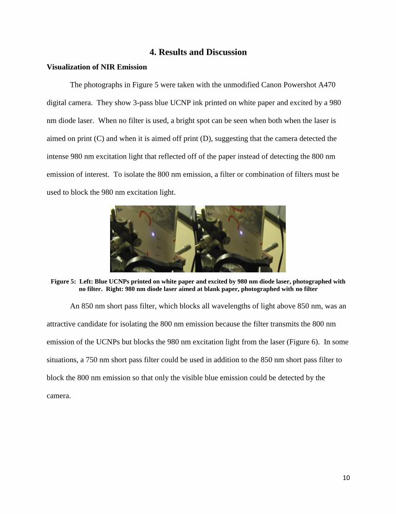
The photographs in Figure 5 were taken with the unmodified Canon Powershot A470
digital camera. They show 3-pass blue UCNP ink printed on white paper and excited by a 980
nm diode laser. When no filter is used, a bright spot can be seen when both when the laser is
aimed on print (C) and when it is aimed off print (D), suggesting that the camera detected the
intense 980 nm excitation light that reflected off of the paper instead of detecting the 800 nm
emission of interest. To isolate the 800 nm emission, a filter or combination of filters must be
used to block the 980 nm excitation light.
Figure 5: Left: Blue UCNPs printed on white paper and excited by 980 nm diode laser, photographed with
no filter. Right: 980 nm diode laser aimed at blank paper, photographed with no filter
An 850 nm short pass filter, which blocks all wavelengths of light above 850 nm, was an
attractive candidate for isolating the 800 nm emission because the filter transmits the 800 nm
emission of the UCNPs but blocks the 980 nm excitation light from the laser (Figure 6). In some
situations, a 750 nm short pass filter could be used in addition to the 850 nm short pass filter to
block the 800 nm emission so that only the visible blue emission could be detected by the
camera.

11
Figure 6: Transmission spectra of 750 nm shortpass filter (red) and 850 nm shortpass filter (black). The
upconversion emission spectrum of NaYF4 is shown for reference in blue.
To test the 850 nm short pass filter, four 3-layer printed circles of blue UCNP ink were
printed on an index card and excited with a 980 nm CW laser (power density of 4 W/cm2). The
modified Canon Powershot, equipped with the 850 nm short pass filter and a 715 long pass filter,
was used to record a video as the card was moved left and right across the stationary laser beam.
Bright spots appeared when the beam passed over the printed UCNPs, and only a dim spot was
visible when the beam passed over unprinted paper, suggesting that 850 nm short pass filter
could effectively block 980 nm excitation light but transmit the 800 nm emission.
100
80
60
40
20
0
Tra
nm
issio
n
900800700600500
Wavelength, nm
750 nm shortpass 850 nm shortpass Blue UCNPs

12
Figure 7 shows a printed UCNP circle excited by a 980 nm laser. The pictures were taken
with the 850 nm short pass filter only, the 850 nm short pass and 715 nm cutoff filters, and the
850 nm short pass and 475 nm cutoff filters, respectively. A bright spot is visible with all three
combinations of filters, suggesting that the 850 nm short pass filter does not block the emissions
of the nanoparticles. The 715 nm cutoff filter blocks visible light, so the bright spot in the center
picture is the 800 nm emission alone. This emission is intense and can be detected by our
camera when the camera is equipped with the 850 short pass filter.
Figure 7: Blue UCNPs printed on white paper and excited by 980 nm diode laser, photographed with 850 nm
short pass filter (left), 850 nm short pass and 715 cutoff filters (center), and 850 nm short pass and 475 nm
cutoff filters (right).
Synthesis and Characterization of UCNPs
Spectroscopic analysis showed that NaYF4 doped with 46.7% Yb and 3.7% Tm produced
the 800 nm emission with the greatest absolute intensity. NaYF4 doped 25% Yb and 0.3% Tm
produced the 800 nm emission with the lowest absolute intensity. When the concentration of Tm
was increased from 0.3% to 2% and then to 3.7%, the visible blue emission was eliminated, but
the absolute intensity of the 800 nm emission increased (Figures 8 and 9).

13
Figure 8: Absolute intensity of NaYF4:Yb/Tm emission under 980 nm excitation. An expansion of the visible
region of the spectrum is shown at right.
Figure 9: Log of the absolute intensity of the 800 nm emission vs. log of the excitation power
Optical observations reinforced the spectroscopic findings. For each combination of
dopant concentrations, a spot of nanoparticles in toluene was smeared on white paper. The
nanoparticles were excited with a 980 nm laser and photographed once with the 850 nm short
pass filter and again with the 850 nm short pass and the 750 nm short pass filters (Figure 10).
7.5
7.0
6.5
6.0
Lo
g In
ten
sit
y (
dN
/dt/
d
)
1.41.21.00.80.6
Log Power (W/cm2)
Log (I) =1.38 ± 0.03 * Log (P) + 4.98 ± 0.03Log (I) =1.47 ± 0.1 * Log (P) + 4.88 ± 0.11Log (I) =1.40 ± 0.02 * Log (P) + 5.45 ± 0.02
25%Yb 0.3%Tm 25%Yb 2%Tm 43.6%Yb 3.7%Tm
1.4x10⁶
1.2
1.0
0.8
0.6
0.4
0.2
0.0
Inte
nsit
y, d
N/d
t/d
900800700600500400
Wavelength, nm
25%Yb 0.3%Tm 46.3%Yb 3.7%Tm 25%Yb 2%Tm
14x103
12
10
8
6
4
2
0
Inte
nsit
y, d
N/d
t/d
700650600550500450400
Wavelength, nm
25%Yb 0.3%Tm 46.3%Yb 3.7%Tm 25% Yb 2%Tm

14
When only the 850 nm short pass filter is used, the camera can detect both the visible blue
emission and the 800 nm emission of the nanoparticles. When the 750 nm short pass filter is
added, the 800 nm emission is blocked and only the visible blue emission can be detected by the
camera. A bright spot is visible in all three photos with the 850 nm short pass filter only, but in
the photos with both the 850 nm short pass and 750 nm short pass filters, the camera can only
detect a significant emission from the 25% Yb and 0.3% Tm nanoparticles.
Figure 10: UCNPs with three different dopant concentrations printed on white paper and excited by 980 nm
diode laser, photographed with 850 nm short pass filter (top) and 850 nm and 750 nm short pass filters
(bottom)
NIR Emission through Opaque Ink
Spots of UCNP in toluene were smeared on white paper and then covered by layers of
Hobbicolor ink with varying density. The ink-covered spots were photographed once using the
modified digital camera with the 850 nm short pass filter to block the excitation light and again
using the camera with both the 850 nm short pass filter and the 750 short pass filter to block the
excitation light as well as the 800 nm emission (Figure 11). When only the 850 nm short pass
filter was used, a bright 800 nm emission was visible through all ink coatings. When the 750 nm
short pass filter blocked the 800 nm emission, the brightness of the blue emission decreased with

15
increasing ink density. No emission was visible when the UCNPs were covered by a 2-pass
layer of Hobbicolor ink.
Figure 11: Blue UCNPs in toluene smeared on white paper and excited by 980 nm diode laser,
photographed with 850 nm short pass filter (right column) and 850 nm and 750 nm short pass filters (left
column). UCNPs were covered in layers of ink of varying density, as described in the diagram at right.
Next, a series of images printed in blue UCNP ink were printed on paper and covered
with a 2-pass layer of Hobbicolor ink (Figure 12). Under 980 nm excitation, the modified
camera could capture well-defined NIR images even when the nanoparticles were completely
covered by opaque ink.
2-Pass Inkjet Ink
No Inkjet Ink
UCNPs
850 nm short pass filter:
800 nm and blue emission
850 nm and 750 nm short pass filters:
blue emission
No Inkjet Ink
2-Pass Inkjet Ink
Increasing Ink Density

16
Figure 12: Blue UCNP ink images printed on white paper and covered by a 2-Pass layer of black Hobbicolor
inkjet ink excited by 980 nm diode laser.
Blue UCNP ink images were then printed on thin layers of clear epoxy resin and covered
with a layer of epoxy mixed with Hobbicolor ink approximately 1 mm thick (Figure 13). Again,
when the UCNP ink was excited through the opaque epoxy coating, the camera could read well-
defined NIR images. These examples demonstrate the potential for NIR-to-NIR printing in anti-
counterfeiting applications. As we anticipated, the NaYF4:Yb/Tm can be excited through an
opaque coating and emit 800 nm light that can also pass through the opaque coating and be
detected by a digital camera.

17
Figure 13: Blue UCNP ink images printed on epoxy and covered by a 1 mm layer of epoxy mixed with black
Hobbicolor inkjet ink excited by 980 nm diode laser. A: USD logo under ambient room light with no
excitation. B: USD logo with excitation light and ambient room light. C: QR code with excitation and
ambient room light. D. QR code with excited in dark room.
6. Conclusion
Initial experiments prove that the 800 nm emission of NaYF4:Yb/Tm can be detected by a
CCD camera even when the nanoparticles are buried under a layer of opaque ink. By increasing
the concentrations of Yb and Tm in the nanoparticles, the intensity of the 800 nm emission can
be increased, and the blue emission can be eliminated, making the nanoparticles an even more
promising candidate for NIR-to-NIR security printing.

18
References
1. Werts, M.H.V. (2000). Luminescent Lanthanide Complexes: Visible Light Sensitised Red
and Near-infrared Luminescence.
2. Suyver, J.F., Grimm, J., van Veen, M.K., Biner, D., Kramer, K.W., & Gudel. (2005).
Upconversion spectroscopy and properties of NaYF4 doped with Er3+, Tm3+ and/or Yb3+.
Journal of Luminescence, 117, 1-12.
3. Meruga, J.M., Baride, A., Cross, W., Kellar, J.J., & May, P.S. (2014) Red-green-blue
printing using luminescence-upconversion inks. Journal of Materials Chemistry C, 2, 2221-
2227.
3. Wang, F., & Liu, X. (2008). Upconversion Multicolor Fine-Tuning: Visible to Near-Infrared
Emission from Lanthanide-Doped NaYF4 Nanoparticles. Journal of the American Chemical
Society, 130, 5642-5643.
4. Yin, A., Zhang, Y., Sun, L., & Yan, C. (2010). Collodial synthesis and blue based multicolor
upconversion emissions of size and composition controlled monodisperse hexagonal
NaYF4:Yb,Tm nanocrystals. Nanoscale, 2, 953-959.
5. Zhao, H., Zhang, X., Wang, X., Gao, H., Zhang, Z., & Cao, W. (2014). Monochromatic
Near-Infrared to Near-Infrared Upconversion Nanoparticles for High-Contrast Fluorescence
Imaging. Journal of Physical Chemistry C., 118, 2820-2825.
6. Cassell, J., & Jaramilla, D. (2012). Reports of Counterfeit Parts Quadruple Since 2009,
Challenging US Defense Industry and National Security. IHS Pressroom.
7. Guin, U., DiMase, D., & Tehranipoor, M. (2013). Counterfeit Integrated Circuits: Detection,
Avoidance, and the Challenges Ahead. Journal of Electronic Testing
Acknowledgments
Funding for this research was provided by the National Science Foundation through a
grant from the Research Experience for Undergraduates program. Special thanks to Dr. Stanley
May, Dr. Alfred Boysen, and Aravind Baride for their guidance, advice, and collaboration.
Thanks also to all faculty, staff, and students at the University of South Dakota and to
collaborators at the South Dakota School of Mines and Technology.