Embed Size (px)
Citation preview
Security Architectures for B3G Mobile Networks
Christos Xenakis, Christoforos Ntantogian
Security Group, Communication Networks Laboratory Department of Informatics and Telecommunications
University of Athens, Greece Email :{xenakis, ntantogian}@di.uoa.gr
Abstract
This paper analyses the security architectures employed in the interworking model that
integrates third-generation (3G) mobile networks and Wireless Local Area Networks
(WLANs), materializing Beyond 3G (B3G) networks. Currently, B3G networks are deployed
using two different access scenarios (i.e., WLAN Direct Access and WLAN 3GPP IP Access),
each of which incorporates a specific security architecture that aims at protecting the involved
parties and the data exchanged among them. These architectures consist of various security
protocols that provide mutual authentication (i.e., user and network authentication), as well as
confidentiality and integrity services to the data sent over the air interface of the deployed
WLANs and specific parts of the core network. The strengths and weaknesses of the applied
security measures are elaborated on the basis of the security services that they provide. In
addition, some operational and performance issues that derives from the application of these
measures in B3G networks are outlined. Finally, based on the analysis of the two access
scenarios and the security architecture that each one employs, this paper presents a comparison
of them, which aims at highlighting the deployment advantages of each scenario and
classifying them in terms of: a) security, b) mobility, and c) reliability.
Keywords: B3G networks, 3G, WLAN, EAP-SIM, EAP-AKA, IKEv2, 802.11i,
1 Introduction
The evolution and successful deployment of Wireless Local Area Networks (WLANs)
worldwide has yielded a demand to integrate them with third-generation (3G) mobile networks.
The key goal of this integration is to develop heterogeneous mobile data networks capable of
supporting new emerging data services, which require high data rates. The effort to develop
such heterogeneous networks, also referred as Beyond 3G (B3G) mobile networks, materializes
1
the vision for the next generation wireless systems, which promise to provide ubiquitous
computing to end users.
Currently, the network architecture [1] that integrates 3G and WLAN specifies two
different access scenarios: (a) the WLAN Direct IP Access and (b) the WLAN 3GPP IP Access. The
first scenario provides to a user IP connection to the public Internet or an intranet via a WLAN
Access Network (WLAN-AN), while the second allows a user to establish connection to the 3G
Packet Switch (PS) services (such as Wireless Application Protocol (WAP), Mobile Multimedia
Services (MMS), Location Based Services (LBS), etc.) or the public Internet through the 3G
Public Land Mobile Network (PLMN). Along with a variety of new perspectives, the new
network model (3G-WLAN) raises new security concerns, mainly, because of the complexity of
the deployed architecture and the heterogeneity of the employed technologies. Thus, the proper
design and a comprehensive evaluation of the security mechanisms used in the 3G-WLAN
network architecture is of vital importance for the effective integration of the different
technologies in a secure manner.
This paper analyses the security architectures of the 3G-WLAN interworking model that
materializes B3G networks. Currently, B3G networks are deployed using two different access
scenarios (i.e., WLAN Direct Access and WLAN 3GPP IP Access), each of which incorporates
a specific security architecture that aims at protecting the involved parties and the data
exchanged among them. These architectures consist of various security protocols that provide
mutual authentication (i.e., user and network authentication), as well as confidentiality and
integrity services to the data sent over the air interface of the deployed WLANs and specific
parts of the core network. The strengths and weaknesses of the applied security measures are
elaborated on the basis of the security services that they provide. In addition, some operational
and performance issues that derives from the application of these measures in B3G networks are
outlined. Finally, based on the analysis of the two access scenarios and the security architecture
that each one employs, this paper presents a comparison of them, which aims at highlighting the
2
deployment advantages of each scenario and classifying them in terms of: a) security, b)
mobility, and c) reliability.
The rest of this paper is organized as follows. Section 2 outlines the B3G network
architecture presenting the two access scenarios (i.e., the WLAN Direct IP and the WLAN 3GPP
IP). Section 3 analyses the security architecture and the specific security measure that each one
of the above access scenarios employs. Section 4 evaluates the employed security measures,
while section 5 compares the security architectures and, consequently, the two access scenarios.
Finally, section 6 contains the conclusions.
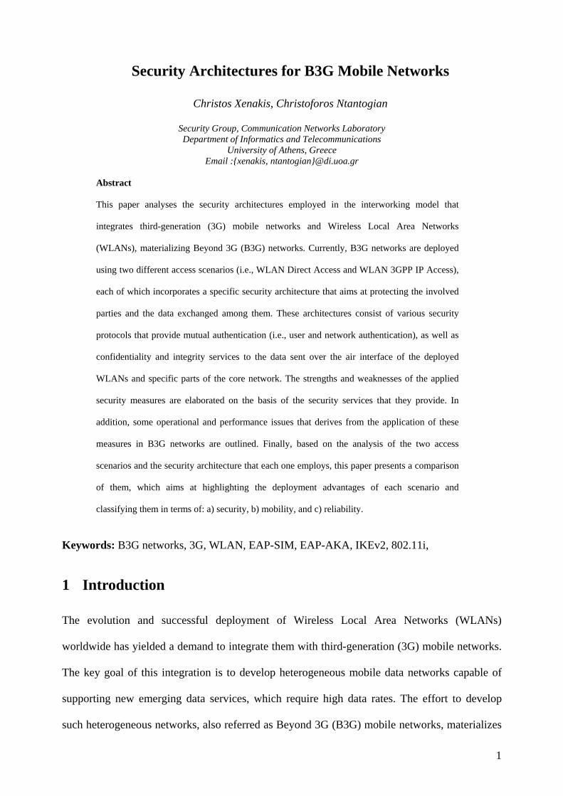
2 B3G Network Architecture
As shown in Fig. 1, the B3G network architecture consists of three individual parts: (I) the
WLAN Access Network (WLAN-AN), (II) the visited 3G PLMN, and (III) the home 3G
PLMN. Note that Fig. 1 illustrates the architecture for a general case where the WLAN is not
directly connected to the user’s home 3G PLMN. The WLAN-AN consist of the wireless
Access Points (APs), which act like Authentication, Authorization, Accounting (AAA) [19]
clients that forward security related messages to the AAA server through AAA proxies, the
Network Access Server (NAS) that provides to the mobile users access to the public internet,
and the WLAN-Access Gateway (WLAN-AG) which is a gateway to 3G PLMN networks. It is
assumed that WLAN is based on the IEEE 802.11 standard [8].
On the other hand, the visited 3G PLMN includes an AAA proxy that forwards AAA
information to the AAA server (located in the home 3G PLMN) and a Wireless Access Gateway
(WAG), which is a data gateway that routes users’ data to the home 3G PLMN. Finally, the
home 3G PLMN includes the AAA server that provides authentication services to the WLAN,
the Packed Data Gateway (PDG) and the core network elements of the Universal Mobile
Telecommunications System (UMTS), such as the Home Subscriber Service (HSS) or the Home
Location Register (HLR), the Authentication Centre (AuC), the Gateway GPRS Support Node
3
(GGSN) and the Serving GPRS Support Node (SGSN). The AAA server retrieves
authentication information from the HSS/HLR and validates authentication credentials provided
by users. The PDG routes user data traffic between a user and an external packet data network,
which is selected based on the 3G PS-services requested by the user. The latter identifies these
services by means of a WLAN-Access Point Name (W-APN) [25], which represents a reference
point to the external IP network that supports the PS services to be accessed by the user.
Fig. 1. B3G network architecture
As mentioned previously, the integrated architecture of B3G networks specifies two
different network access scenarios [1]: (a) the WLAN Direct IP Access and (b) the WLAN 3GPP
IP Access. The first scenario provides to a user connection to the public Internet or to an intranet
via the WLAN-AN. In this scenario both the user and the network are authenticated to each
other using the EAP-SIM [11] or the EAP-AKA [12] protocol. Moreover, in this scenario, the
confidentiality and integrity of users’ data transferred over the air interface are ensured by the
802.11i security framework [6]. On the other hand, the WLAN 3GPP IP Access scenario allows
a user to connect to the PS services (like WAP, MMS, LBS, etc.) or to the public Internet
through the 3G PLMN. In this scenario, the user is authenticated to the 3G PLMN using the
EAP-SIM or alternatively the EAP-AKA protocol encapsulated within IKEv2 [13] messages.
The execution of IKEv2 is also used for the establishment of an IPsec-based VPN [21] tunnel
4
between the user and the PDG that provides confidentiality and integrity services to the data
exchanged between them (see Fig. 1).
3 Security Architectures for B3G Networks
Each network access scenario (i.e., WLAN Direct Access and WLAN 3GPP IP Access) in B3G
networks incorporates a specific security architecture, which aims at protecting the involved
parties (i.e., the mobile users, the WLAN and the 3G network) and the data exchanged among
them. These architectures [2] consist of various security protocols that provide mutual
authentication (i.e., user and network authentication) as well as confidentiality and integrity
services to the data sent over the air interface of the deployed WLANs and specific parts of the
core network. In the following, the security architectures and the involved security protocols,
which are employed in B3G networks, are presented and analyzed focusing on their
functionality and the supported security services.
3.1 WLAN Direct IP Access scenario
In the WLAN Direct IP Access scenario, both the user and the network are authenticated to each
other using EAP-SIM or EAP-AKA, which are based on the 802.1X port access control [7].
After a successful authentication, the user obtains an IP address from the WLAN-AN and then
he gets access to the public Internet or an intranet, depending on the requested service. In this
scenario, the confidentiality and integrity of user’s data conveyed over the air interface of
WLAN are ensured by the security mechanisms of 802.11i [6], which are analyzed bellow.
3.1.1 Authentication The specific security protocol (i.e., EAP-AKA or EAP-SIM) that will be used for mutual
authentication between the user and the network depends on the user’s subscription. If the user
possesses a UMTS Subscribers Identity Module (USIM) card [4], then, the EAP-AKA protocol
is employed. Otherwise, EAP-SIM is used in cases that the user has a SIM-card [5] of Global
5
System for Mobile communications (GSM)/General Packet Radio Service (GPRS). When the
AAA server receives the user’s identity, it fetches from the HSS/HLR the user’s profile in order
to determine the authentication protocol that will be employed (i.e., EAP-SIM or EAP-AKA). In
the following, we analyze the functionality of these two protocols focusing on the security
services that each one provides.
EAP-SIM EAP-SIM [11] provides mutual authentication in a network environment that integrates 3G and
WLANs, using the credentials included in a SIM-card of a GSM/GPRS subscription. It involves
a user, an AAA client (which is actually a wireless AP), and an AAA server that obtains
authentication information (i.e., authentication triplets) from the HSS/HLR of the network
where the user is subscribed (see Fig. 2). EAP-SIM incorporates two basic enhancements that
eliminate known security weaknesses of the authentication and key agreement procedure of
GSM/GPRS [11]. First, the key used for encryption in EAP-SIM is enhanced to have 128-bits
security, in contrast to the 64-bit security of the original GSM/GPRS key. Second, EAP-SIM
supports mutual authentication, in contrast to the GSM/GPRS authentication, which performs
only user to network authentication.
For the generation of stronger keys, the EAP-SIM protocol combines n (n=2 or n=3)
individual RANDs that result in the derivation of n session keys, Kc. These keys are combined
with a random number (NONCE payload), the user identity and other context-related
information in order to generate the Master Key (MK) of the EAP-SIM protocol, as shown in the
formula below:
MK= SHA1(Identity| n*Kc| NONCE| Version List| Selected Version)1, (1)
where SHA1 is a hash function [18]. In the sequel, the produced key MK is used as input to a
pseudo random function (prf) that generates other keys used in EAP-SIM. From these keys the
most important are: (a) the Master Session Key (MSK), which is used in 802.11i to generate the
1 ( | means string concatenetation and the notation n*Kc denotes the n Kc keys concatenated)
6
encryption keys, as described later on, and (b) the K_auth key, which is used in EAP-SIM for
the generation of keyed Message Authentication Codes (MACs) for authentication purposes.
Fig. 2 The EAP-SIM authentication and session key agreement procedure
Fig. 2 shows the message exchange of EAP-SIM between the user and the AAA server.
Note that the user communicates with the wireless AP via the EAP over LAN (EAPOL)
protocol [7]. First, the user associates with the wireless AP and the latter sends an EAP-
Request/Identity message to the user asking for his identity. The user responds with a message
(EAP- Response/Identity) that includes his identity in the format of Network Access Identifier
(NAI) [20]. This identity can be either the International Mobile Subscriber Identity (IMSI), or a
temporary identity (i.e., pseudonym). Knowing the user’s identity, the AAA server issues an
EAP-Request/SIM/Start message, which actually starts the authentication procedure. The user
sends back an EAP-Response/SIM/Start message that includes a nonce parameter (NONCE),
which is the user’s challenge to the network. Upon receiving this message, the AAA server
communicates with HSS/HLR and obtains n (n=2 or n=3) authentication triplets (RAND, SRES,
Kc) for the specific user (the holder of the SIM-card). The generation of the GSM authentication
7
triplets is based on a permanent, pre-shared (between the user and the network) secret key, Ki,
which is assigned to the user when the latter is subscribed to the GSM/GPRS network. Then, the
AAA server sends to the user an EAP-Request/SIM/Challenge message, which contains the n
RANDs and the MACserver of the message payload, which is calculated using the K_auth key as
follows:
MACserver=HMAC_SHA1K_auth(EAP-Request/SIM/Challenge(n*RAND)| NONCE)1, (2)
where NONCE is the nonce sent by the user to the AAA server, and HMAC-SHA1 [23] is the
MAC algorithm that generates the keyed hash value. Before the calculation of the MACserver
value, the AAA server must first generate the MK key (see eq. (1)), and, subsequently, the
K_auth and MSK keys. Upon receiving the EAP-Request/SIM/Challenge, the user executes the
GSM/GPRS authentication algorithms n times (one for each received RAND), in order to
produce the n Kc keys and the n XRES values. In the sequel, using the produced n Kc keys he
generates the MK (see eq. (1)), and, consequently, the K_auth and the MSK keys, similarly, to
the AAA server. Next, the user verifies the MACserver using the K_auth key, and if this check is
successful, then, the network is authenticated to the user, and the latter conveys to the AAA
server the generated n XRES values within an EAP-Response/SIM/Challenge message. This
message also includes the MACuser value generated as follows:
MACuser=HMAC-SHA1K_auth(EAP-Response/SIM/Challenge(n*XRES) | n*XRES)2, (3)
Upon receiving this message, the AAA server examines whether the produced MACuser
is valid and if the n XRES values are equal to the n SRES values received from HSS/HLR for
authentication. If these checks are successful, the AAA server sends an EAP-Success message
to the user indicating the successful completion of the authentication procedure. In addition, the
AAA server sends to the wireless AP the session key MSK within an AAA message (e.g.,
Radius [24] or Diameter [17]). At this point, both the user and the network are mutually
1 (The notation n*RAND denotes the n RAND values concatenated) 2 (The notation n*XRES denotes the n XRES values concatenated)
8
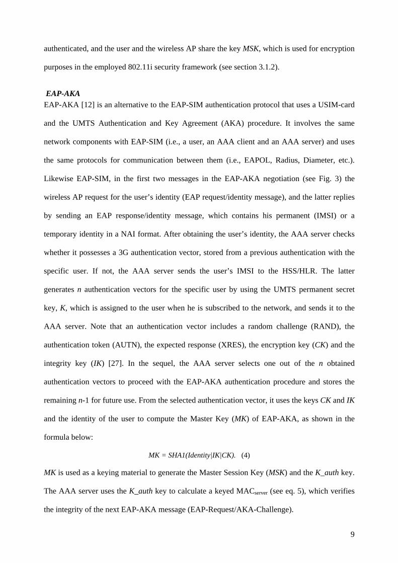
authenticated, and the user and the wireless AP share the key MSK, which is used for encryption
purposes in the employed 802.11i security framework (see section 3.1.2).
EAP-AKA EAP-AKA [12] is an alternative to the EAP-SIM authentication protocol that uses a USIM-card
and the UMTS Authentication and Key Agreement (AKA) procedure. It involves the same
network components with EAP-SIM (i.e., a user, an AAA client and an AAA server) and uses
the same protocols for communication between them (i.e., EAPOL, Radius, Diameter, etc.).
Likewise EAP-SIM, in the first two messages in the EAP-AKA negotiation (see Fig. 3) the
wireless AP request for the user’s identity (EAP request/identity message), and the latter replies
by sending an EAP response/identity message, which contains his permanent (IMSI) or a
temporary identity in a NAI format. After obtaining the user’s identity, the AAA server checks
whether it possesses a 3G authentication vector, stored from a previous authentication with the
specific user. If not, the AAA server sends the user’s IMSI to the HSS/HLR. The latter
generates n authentication vectors for the specific user by using the UMTS permanent secret
key, K, which is assigned to the user when he is subscribed to the network, and sends it to the
AAA server. Note that an authentication vector includes a random challenge (RAND), the
authentication token (AUTN), the expected response (XRES), the encryption key (CK) and the
integrity key (IK) [27]. In the sequel, the AAA server selects one out of the n obtained
authentication vectors to proceed with the EAP-AKA authentication procedure and stores the
remaining n-1 for future use. From the selected authentication vector, it uses the keys CK and IK
and the identity of the user to compute the Master Key (MK) of EAP-AKA, as shown in the
formula below:
MK = SHA1(Identity|IK|CK). (4)
MK is used as a keying material to generate the Master Session Key (MSK) and the K_auth key.
The AAA server uses the K_auth key to calculate a keyed MACserver (see eq. 5), which verifies
the integrity of the next EAP-AKA message (EAP-Request/AKA-Challenge).
9
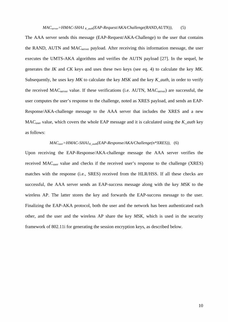
MACserver=HMAC-SHA1 K_auth(EAP-Request/AKA/Challenge(RAND,AUTN)), (5)
The AAA server sends this message (EAP-Request/AKA-Challenge) to the user that contains
the RAND, AUTN and MACserver payload. After receiving this information message, the user
executes the UMTS-AKA algorithms and verifies the AUTN payload [27]. In the sequel, he
generates the IK and CK keys and uses these two keys (see eq. 4) to calculate the key MK.
Subsequently, he uses key MK to calculate the key MSK and the key K_auth, in order to verify
the received MACserver value. If these verifications (i.e. AUTN, MACserver) are successful, the
user computes the user’s response to the challenge, noted as XRES payload, and sends an EAP-
Response/AKA-challenge message to the AAA server that includes the XRES and a new
MACuser value, which covers the whole EAP message and it is calculated using the K_auth key
as follows:
MACuser=HMAC-SHA1K_auth(EAP-Response/AKA/Challenge(n*XRES)), (6)
Upon receiving the EAP-Response/AKA-challenge message the AAA server verifies the
received MACuser value and checks if the received user’s response to the challenge (XRES)
matches with the response (i.e., SRES) received from the HLR/HSS. If all these checks are
successful, the AAA server sends an EAP-success message along with the key MSK to the
wireless AP. The latter stores the key and forwards the EAP-success message to the user.
Finalizing the EAP-AKA protocol, both the user and the network has been authenticated each
other, and the user and the wireless AP share the key MSK, which is used in the security
framework of 802.11i for generating the session encryption keys, as described below.
10
Fig. 3 The EAP-AKA authentication procedure and session key agreement
3.1.2 Data protection (802.11i standard)
As mentioned previously, 802.11i is employed to provide confidentiality and integrity services
to users’ data conveyed over the radio interface of the deployed WLANs in the WLAN Direct
IP Access scenario. The 802.11i standard was developed to enhance the security services
provided in WLANs. Its design was motivated by the fact that the WEP protocol, due to its
security flaws, could not adequately fulfill the security requirements of WLANs [32]. The
design goal of 802.11i is twofold: a) to provide session key management by specifying a four
way handshake and group key handshake procedures, and b) to enhance the confidentiality and
integrity services provided to users’ data by incorporating two security protocols: (i) the
Counter-Mode/CBC-MAC Protocol (CCMP), which employs the Advanced Encryption
Algorithm (AES), and (ii) the Temporal Key Integrity Protocol (TKIP), which uses the same
encryption (RC4) with WEP. In the following, we analyze the four-way and group key
handshake procedures of 802.11i, and we present the functional details of the CCMP protocol.
Since the TKIP protocol is considered to be a short term solution and it is merely a software
enhancement of WEP, we don’t elaborate further on it.
11
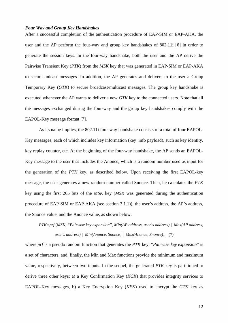
Four Way and Group Key Handshakes After a successful completion of the authentication procedure of EAP-SIM or EAP-AKA, the
user and the AP perform the four-way and group key handshakes of 802.11i [6] in order to
generate the session keys. In the four-way handshake, both the user and the AP derive the
Pairwise Transient Key (PTK) from the MSK key that was generated in EAP-SIM or EAP-AKA
to secure unicast messages. In addition, the AP generates and delivers to the user a Group
Temporary Key (GTK) to secure broadcast/multicast messages. The group key handshake is
executed whenever the AP wants to deliver a new GTK key to the connected users. Note that all
the messages exchanged during the four-way and the group key handshakes comply with the
EAPOL-Key message format [7].
As its name implies, the 802.11i four-way handshake consists of a total of four EAPOL-
Key messages, each of which includes key information (key_info payload), such as key identity,
key replay counter, etc. At the beginning of the four-way handshake, the AP sends an EAPOL-
Key message to the user that includes the Anonce, which is a random number used as input for
the generation of the PTK key, as described below. Upon receiving the first EAPOL-key
message, the user generates a new random number called Snonce. Then, he calculates the PTK
key using the first 265 bits of the MSK key (MSK was generated during the authentication
procedure of EAP-SIM or EAP-AKA (see section 3.1.1)), the user’s address, the AP’s address,
the Snonce value, and the Anonce value, as shown below:
PTK=prf (MSK, “Pairwise key expansion”, Min(AP address, user’s address) | Max(AP address,
user’s address) | Min(Anonce, Snonce) | Max(Anonce, Snonce)), (7)
where prf is a pseudo random function that generates the PTK key, “Pairwise key expansion” is
a set of characters, and, finally, the Min and Max functions provide the minimum and maximum
value, respectively, between two inputs. In the sequel, the generated PTK key is partitioned to
derive three other keys: a) a Key Confirmation Key (KCK) that provides integrity services to
EAPOL-Key messages, b) a Key Encryption Key (KEK) used to encrypt the GTK key as
12
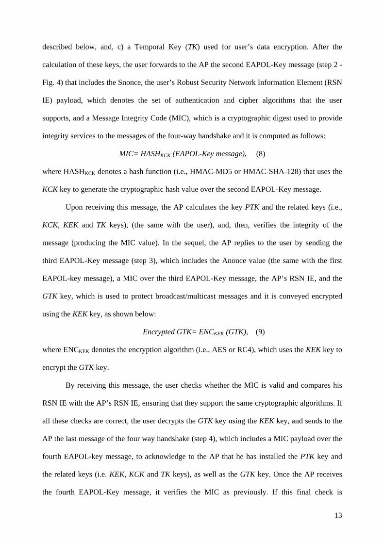
described below, and, c) a Temporal Key (TK) used for user’s data encryption. After the
calculation of these keys, the user forwards to the AP the second EAPOL-Key message (step 2 -
Fig. 4) that includes the Snonce, the user’s Robust Security Network Information Element (RSN
IE) payload, which denotes the set of authentication and cipher algorithms that the user
supports, and a Message Integrity Code (MIC), which is a cryptographic digest used to provide
integrity services to the messages of the four-way handshake and it is computed as follows:
MIC= HASHKCK (EAPOL-Key message), (8)
where HASHKCK denotes a hash function (i.e., HMAC-MD5 or HMAC-SHA-128) that uses the
KCK key to generate the cryptographic hash value over the second EAPOL-Key message.
Upon receiving this message, the AP calculates the key PTK and the related keys (i.e.,
KCK, KEK and TK keys), (the same with the user), and, then, verifies the integrity of the
message (producing the MIC value). In the sequel, the AP replies to the user by sending the
third EAPOL-Key message (step 3), which includes the Anonce value (the same with the first
EAPOL-key message), a MIC over the third EAPOL-Key message, the AP’s RSN IE, and the
GTK key, which is used to protect broadcast/multicast messages and it is conveyed encrypted
using the KEK key, as shown below:
Encrypted GTK= ENCKEK (GTK), (9)
where ENCKEK denotes the encryption algorithm (i.e., AES or RC4), which uses the KEK key to
encrypt the GTK key.
By receiving this message, the user checks whether the MIC is valid and compares his
RSN IE with the AP’s RSN IE, ensuring that they support the same cryptographic algorithms. If
all these checks are correct, the user decrypts the GTK key using the KEK key, and sends to the
AP the last message of the four way handshake (step 4), which includes a MIC payload over the
fourth EAPOL-key message, to acknowledge to the AP that he has installed the PTK key and
the related keys (i.e. KEK, KCK and TK keys), as well as the GTK key. Once the AP receives
the fourth EAPOL-Key message, it verifies the MIC as previously. If this final check is
13
successful, the four-way handshake is completed successfully, and both the user and the AP
share the TK and the GTK keys to encrypt/decrypt unicast and broadcast/multicast messages,
respectively.
In case that the AP wants to provide a new GTK key to the connected users, it executes
the group key handshake. As shown in Fig. 4, the AP first sends an EAPOL-Key message that
includes a MIC value and a new GTK key to the users. Note that MIC is computed over the
body of this EAPOL-Key message using the KCK key, and the GTK key is conveyed encrypted
using the KEK key. Recall that both the user and the AP share the KEK and KCK keys, which
were generated in the four-way handshake. Upon receiving the previous message, the user
employs the KCK key to verify whether the MIC is valid and then he decrypts the GTK key
using the KEK key. Finally, he replies to the AP with an EAPOL-Key message, which includes
a MIC that acknowledges to the AP that he has installed the GTK key. Once the AP receives this
message, it verifies the MIC. If this final verification is successful, then, the group key
handshake is completed successfully and the user can encrypt broadcast/multicast messages
using the new GTK key.
Fig. 4 The four-way and Group key handshakes of 802.11i.
14
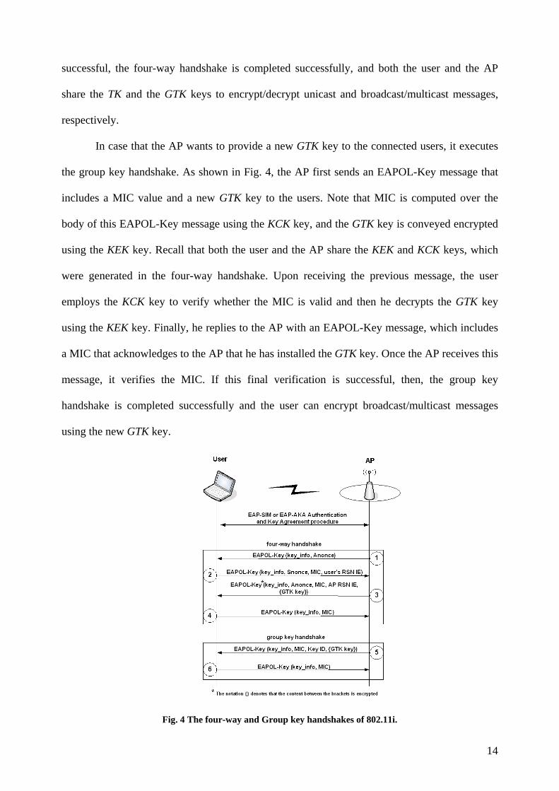
CCMP Protocol 802.11i incorporates the CCMP protocol to provide confidentiality and integrity services to
users’ data conveyed over the radio interface of WLANs. The CCMP protocol combines the
AES encryption algorithm in CounTeR mode (CTR-AES) to provide data confidentiality and
the Cipher Block Chaining Message Authentication Code (CBC-MAC) protocol to compute a
MIC over the transmitted user’s data that provides message integrity [16].
The operation of the CCMP protocol can be divided into three distinct phases. In phase
1, the CCMP protocol constructs an Additional Authentication Data (AAD) value from constant
fields of the 802.11 frame header (see Fig. 5) [6][8]. In addition, it creates the nonce value from
the priority field of the 802.11 frame header and the Packet Number (PN) parameter, which is a
48-bit counter incremented for each 802.11i protected frame. In phase 2, the CCMP protocol
computes a MIC value over the 802.11 frame header, the AAD, the nonce, and the 802.11 frame
payload using the CBC-MAC algorithm and the TK key (or the GTK key for broadcast/mulitcast
communication). Recall that the TK key is part of the PTK key that is generated in the four-way
handshake. In the sequel, CCMP forms the cipher text of the 802.11 frame payload and the
produced MIC, using the CTR-AES encryption algorithm and the TK key (or the GTK key).
Finally, in phase 3, the CCMP protocol constructs the 802.11i frame from the concatenation of:
(i) the 802.11 header, (ii) the CCMP header, which is created from the PN parameter and the
identity of the encryption key, (iii) the cipher text, and (iv) the 802.11 trailer (see Fig. 5). The
receiver of the 802.11i frame must verify that the PN parameter is fresh and the MIC value is
valid. If these checks are successful, then, the receiver decrypts the 802.11i frame payload using
the TK key (or the GTK key).
15
Fig. 5 The CCMP protocol
3.2 WLAN 3GPP IP Access
In contrast to the WLAN Direct IP Access scenario, in which a user gets access to the public
Internet, directly, through the WLAN AN, the WLAN 3GPP IP Access scenario provides to the
WLAN user access to the PS services or the Internet through the 3G PLMN. Before getting
access to them, the user must perform the six (6) discrete steps, presented in Fig. 6 and
described bellow:
16
Fig. 6 3GPP IP Access authentication procedure
1. Initial authentication. The user and the network are authenticated each other using
either the EAP-SIM or EAP-AKA protocol. This authentication step enables the user to
obtain a local IP address, called Transport IP address, which is used for access to the
WLAN environment and the PDG. Note that this initial authentication can be omitted, if
the PDG trusts the WLAN network and its users.
2. After the EAP-SIM or EAP-AKA execution, the four-way handshake and optionally the
group key handshake follow to provide the 802.11i session keys. Then, the
communication between the user and the wireless AP is encrypted using the CCMP or
alternatively the TKIP protocol.
3. After the completion of the initial authentication step and the 802.11i handshakes, the
user communicates with the DHCP server to obtain the Transport IP address. This local
address is used by the user to execute the IKEv2 in the following step 4.
17
4. The user retrieves the IP address of the PDG using the W-APN identity and the DNS
protocol. Thus, the user and the PDG participate in a second authentication step that
combines IKEv2 and EAP-SIM or EAP-AKA.
5. Second authentication. The user and the PDG execute the IKEv2 negotiation protocol,
which encapsulates either EAP-SIM or EAP-AKA for authentication of the negotiating
peers. After authentication completion, the user obtains a global IP address, called
Remote IP address, which is used for access to the PS services and the public Internet
via the 3G PLMN. In addition, the execution of IKEv2 results in the establishment of a
pair of IPsec Security Associations (SAs) between the user and the PDG, which are used
for the deployment of an IPsec-based Virtual Private Network (VPN).
6. The deployed IPsec based VPN protects user’s data exchanged between the user and the
PDG (in both directions), ensuring data origin authentication, data confidentiality and
message integrity.
Fig. 7 3GPP IP Access authentication protocol stack
Fig. 7 presents the protocol stack used in the 3GPP IP Access scenario for each entity
that participates in the authentication procedure. The main authentication protocol is EAP-SIM
or EAP-AKA, which is executed between the user and the AAA server. The user encapsulates
EAP-SIM or EAP-AKA messages within IKEv2 and conveys them to the PDG. The latter
acting as an AAA client transfers the EAP-SIM or EAP-AKA messages to the AAA server
using an AAA protocol. Note that the AAA protocol can be either RADIUS, which runs over
18
the User Datagram Protocol (UDP) or Diameter, which runs typically over the TCP protocol.
The AAA server also includes the Mobile Application Part (MAP) protocol stack to be able to
communicate with the HSS/HLR and obtain authentication triplets and authorization
information.
From the above steps that a user has to perform to get access to the PS services or the public
Internet in the WLAN 3GPP IP Access scenario, the initial authentication using either EAP-SIM
or EAP-AKA (step 1) and the 802.11i handshakes (step 2) are the same with these of the
WLAN Direct IP Access scenario, which have been analyzed in sections 3.1.1 and 3.1.2.
Moreover, the acquisition of a local IP address (step 3) and the retrieval of the PDG address
(step 4) do not present any significant interest from a security point of view. Thus, in the
following sections we analyze the second authentication step (step 5), which includes a
combined execution of IKEv2 with EAP-SIM or EAP-AKA, and the deployment of a
bidirectional VPN that protects data exchanged.
3.2.1 Authentication
IKEv2 [13] is a simplified redesign of IKE that allows two peers to authenticate each other (i.e.,
mutual authentication) and derive keys for secure communication with IPsec. The exchanged
messages within IKEv2 are protected ensuring confidentiality and integrity, while the peers are
authenticated using certificates, pre-shared keys or the EAP protocol. In the context of the
WLAN 3GPP IP Access scenario, the user and the PDG execute IKEv2. The authentication of
the user is based on EAP-SIM or EAP-AKA, while the authentication of the PDG is based on
certificates.
Similarly to IKE, the IKEv2 protocol is executed in two sequential phases (i.e., phase 1
and phase 2). In phase 1, the user and the PDG establish two distinct SAs: a) a bidirectional
IKE_SA that protects the messages of phase 2, and b) an one way IPsec_SA that protects user’s
data. During phase 2, the user and the PDG using the established IKE_SA can securely
19
negotiate a second IPsec_SA that is employed for the establishment of a bidirectional IPsec-
based VPN tunnel between them.
Fig. 8 The execution of IKEv2 based on EAP-SIM or EAP-AKA
The IKEv2 phase 1 negotiation between the user and the PDG is executed in two sub-
phases: (a) the IKE_SA_INIT and (b) the IKE_AUTH exchange, as shown in Fig. 8. The
IKE_SA_INIT exchange (noted as step 1 in Fig. 8) consists of a single request and reply
messages, which negotiate cryptographic algorithms, exchange nonces, and do a Diffie-Hellman
exchange. In the context of this sub-phase, four cryptographic algorithms are negotiated: (a) an
encryption algorithm, (b) an integrity protection algorithm, (c) a Diffie-Hellman group, and (d)
a pseudo-random function (prf). The latter (prf) is employed for the construction of keying
20
material for all of the cryptographic algorithms used. After the execution of the IKE_SA_INIT,
an IKE_SA is established that protects the IKE_AUTH exchange. The second sub-phase (i.e.,
IKE_AUTH) authenticates the previous messages, exchanges identities and certificates,
encapsulates EAP-SIM or alternatively EAP-AKA messages, and establishes an IPsec_SA (step
2-5 in Fig. 8). All the messages of IKEv2 include a header payload (HDR), which contains a
Security Parameter Index (SPI), a version number, and security related flags. The SPI is a value
chosen by the user and the PDG to identify a unique SA.
At the beginning of the IKEv2 negotiation (step 1 in Fig. 8), the user sends to the PDG
the SAi1, which denotes the set of cryptographic algorithms for the IKE_SA that he supports,
the KEi that is the Diffie-Hellman value, and a Ni value that represents the nonce. The nonce
(i.e., a random number at least 128 bits) is used as input to the cryptographic functions
employed by IKEv2 to ensure liveliness of the keying material and protect against replay
attacks. The PDG answers with a message that contains its choice from the set of cryptographic
algorithms for the IKE SA (SAr1), its value to complete the Diffie-Hellman exchange (KEr) and
its nonce (Nr).
At this point, both the user and the PDG can calculate the SKEYSEED value as follows:
)^),|(( irgNrNiprfSKEYSEED = 1, (10)
where prf is the pseudorandom function negotiated in the previous messages, and g^ir is the
shared secret key that derives from the Diffie-Hellman exchange. The SKEYSEED value is
used to calculate various secret keys. The most important are: the SK_d used for providing the
keying material for the IPsec SA; SK_ei and SK_ai used for encrypting and providing integrity
services, respectively, to the IKEv2 messages from the user to the PDG (IKE_SA); and, finally,
SK_er and SK_ar that provide security services in the opposite direction (IKE_SA).
Finalizing the IKE_SA_INIT exchange, the IKE_AUTH exchange can start. It is worth
noting that from this point all the payloads of the following IKEv2 messages, excluding the
1 | means string concatenation
21
message header (HDR payload), are encrypted and integrity protected using the IKE_SA (see
step 2 in Fig. 8). The IKE_AUTH exchange of messages starts when the user sends to the PDG
a message that includes his identity (IDi), which could be in a NAI format, the CERTREQ
payload (optionally), which is a list of the Certificate Authorities (CA) whose public keys the
user trusts, and the traffic selectors (TSi and TSr), which allow the peers to identify the packet
flows that require processing by IPsec. In addition, in the same message the user must include
the Configuration Payload Request (CP-Request), which is used to obtain a Remote IP address
from the PDG and get access to the 3G-PLMN.
After receiving this information, the PDG forwards to the AAA server the user identity
(IDi) including a parameter, which indicates that the authentication is being performed for VPN
tunnel establishment. This will facilitate the AAA server to distinguish between authentications
for WLAN access and authentications for VPN setup. Upon receiving the IDi, the AAA server
fetches the user’s profile and authentication credentials (GSM triplets if authentication is based
on EAP-SIM, or 3G authentication vectors if authentication is based on EAP-AKA) from
HSS/HLR (if these are not available in the AAA server in advance). Based on the user’s profile,
the AAA server initiates an EAP-AKA (if the user possesses a USIM card) or an EAP-SIM
authentication (if the user possesses a GSM/GPRS SIM card) by sending to the PDG the first
message of the related procedure (i.e., EAP-SIM or EAP-AKA) included in a AAA protocol
(i.e., Radius or Diameter) (step 3 in Fig. 8). Note that since there is no functional difference
between the EAP-SIM and the EAP-AKA authentication when these protocols are encapsulated
in IKEv2, we present them in a generic way. Thus, we introduce the EAP-AKA (SIM) payload
notation (see Fig. 8) to indicate that this payload can be an EAP-SIM or an EAP-AKA message.
Upon receiving the first EAP-AKA (SIM) message, the PDG encapsulate it within an
IKEv2 message and forwards the encapsulated message to the user. Except for the EAP-AKA
(SIM) payload, this message also includes the PDG’s identity, which identifies the provided 3G
services (W-APN) (see sect. 2), the PDG’s certificate (CERT), and the AUTHr field. The latter
22
contains signed data used by the user to authenticate the PDG. Similarly to the previous
messages, the payload of this IKEv2 message, except for the message header, is encrypted using
the IKE_SA. Upon receiving the EAP-AKA (SIM) payload, the user verifies the AUTHr field
by using the public key of the PDG included in the certificate field (CERT), and answers by
sending an EAP-AKA (SIM) response message encapsulated again within an IKEv2 message.
From this point, the IKEv2 messages contain only EAP-AKA (SIM) payloads, which are
encrypted and integrity protected as described previously. The EAP-SIM or EAP-AKA
exchange continues, normally, until an EAP-SUCCESS message (or an EAP-FAILURE in case
of a failure) is sent from the AAA server to the PDG, which ends the EAP-AKA or the EAP-
SIM dialogue. Together with the EAP-SUCCESS message, the key MSK is sent from the AAA
server to the PDG via the AAA protocol, as shown in Fig. 8 (step 4).
After finishing the EAP-AKA or EAP-SIM dialogue, the last step (step 5) of IKEv2 re-
authenticates the peers, in order to establish an IPsec_SA. This authentication step is necessary
in order defeat man-in-the-middle attacks, which might take place because the authentication
protocol (e.g., EAP-SIM or EAP-AKA) runs inside the secure protocol (e.g., IKEv2). This
combination creates a security hole since the initiator and the responder have no way to verify
that their peer in the authentication procedure is the entity at the other end of the outer protocol
[30]. Thus, in order to prevent possible attacks against IKEv2 (i.e., man in the middle attacks),
both the user and the PDG have to calculate the AUTHi and the AUTHr payloads, respectively,
using the MSK key that was generated from the EAP-SIM or EAP-AKA protocol. Then, both
the user and the PDG send each other the AUTHi and AUTHr payloads to achieve a security
binding between the inner protocol (EAP-SIM or EAP-AKA) and the outer protocol (IKEv2).
Note that the PDG together with the AUTHr payload sends also its traffic selector payloads (TSi
and TSr), the SAr2 payload, which contains the chosen cryptographic suit for the IPsec_SA and
the assigned user’s Remote IP address in the Configuration Payload Reply (CP-REPLY)
23
payload. After the establishment of the IPsec_SA the keying material (KEYMAT) for this SA is
calculated as follows:
)|,_( NrNidSKprfKEYMAT = , (11)
where Ni and Nr are the nonces from the IKE_SA_INIT exchange, and SK_d is the key that is
calculated from the SKEYSEED value (see eq. 10). The KEYMAT is used to extract the keys
that the IPsec protocol uses for security purposes. Note that the deployed IPsec_SA protects the
one way communication between the user and the PDG. For bi-directional secure
communication between them, one more SA needs to be established (between the PDG and the
user) by executing the IKEv2 phase 2 over the established IKE_SA.
3.2.2 Data protection
After the completion of the authentication procedure and the execution of IKEv2 between the
PDG and the user, a pair of IPsec_SAs has been established between these two nodes. This pair
deploys a bidirectional VPN between them that allows for secure data exchange over the
underlying network path. At the same time, the user has been subscribed to the 3G PLMN
network for charging and billing purposes using either the EAP-AKA or EAP-SIM protocol.
The deployed VPN runs on top of the wireless link and extends from the user’s computer
to the PDG, which is located in the user’s home 3G PLMN (see Fig. 1). It is based on IPsec
[21], which is a developing standard for providing security at the network layer. IPsec provides
two choices of security service through two distinct security protocols: the Authentication
Header (AH) [15] protocol, and the Encapsulating Security Payload (ESP) protocol [22]. The
AH protocol provides support for connectionless integrity, data origin authentication and
protection against replays, but it does not support confidentiality. The ESP protocol supports
confidentiality, connectionless integrity, anti-replay protection and optional data origin
authentication. Both AH and ESP support two modes of operation: transport and tunnel. The
transport mode of operation provides end-to-end protection between the communicating end-
24
points by encrypting the IP packet payload. The tunnel mode encrypts the entire IP packet (both
IP header and payload) and encapsulates the encrypted original IP packet in the payload of a
new IP packet.
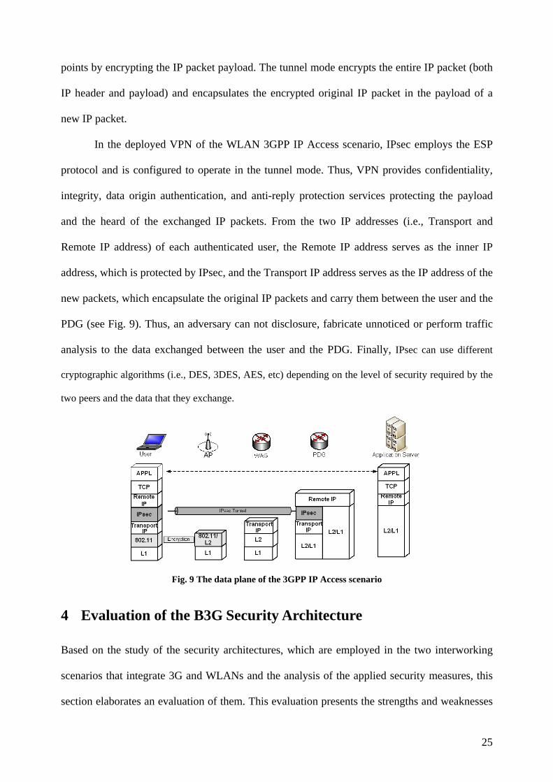
In the deployed VPN of the WLAN 3GPP IP Access scenario, IPsec employs the ESP
protocol and is configured to operate in the tunnel mode. Thus, VPN provides confidentiality,
integrity, data origin authentication, and anti-reply protection services protecting the payload
and the heard of the exchanged IP packets. From the two IP addresses (i.e., Transport and
Remote IP address) of each authenticated user, the Remote IP address serves as the inner IP
address, which is protected by IPsec, and the Transport IP address serves as the IP address of the
new packets, which encapsulate the original IP packets and carry them between the user and the
PDG (see Fig. 9). Thus, an adversary can not disclosure, fabricate unnoticed or perform traffic
analysis to the data exchanged between the user and the PDG. Finally, IPsec can use different
cryptographic algorithms (i.e., DES, 3DES, AES, etc) depending on the level of security required by the
two peers and the data that they exchange.
Fig. 9 The data plane of the 3GPP IP Access scenario
4 Evaluation of the B3G Security Architecture
Based on the study of the security architectures, which are employed in the two interworking
scenarios that integrate 3G and WLANs and the analysis of the applied security measures, this
section elaborates an evaluation of them. This evaluation presents the strengths and weaknesses
25
of the applied security measures on the basis of the security services that they provide, as well
as some operational and performance issues that their deployment might result in.
4.1 EAP-SIM
Although EAP-SIM was designed as an advanced authentication protocol, it does not meet its
security goals. An essential drawback of the EAP-SIM authentication procedure is related to the
fact that its sessions are not independent [34]. Specifically, if some authentication triplets of a
user are compromised, then an adversary may use them to authenticate himself to the user as
valid network. The ways in which an adversary can obtain authentication triplets are: (i) having
physical access to the SIM-card of the user, (ii) using a malicious piece of software that attacks
against the user platform, (iii) performing attacks on the GSM/GPRS network (it is assumed that
the same authentication triplets are used for both GSM/GPRS and WLAN access), and (iv)
getting access to the communication between the AuC and the AAA server that exchange
authentication information.
Obtaining authentication triplets the adversary may impersonate a valid network and
calculate valid keys. More specifically, he is able to calculate a valid MACserver value (see eq.
(2)) and the related K_auth key, as he possesses valid authentication triplets. Based on the
received MACserver value the user authenticates the attacker as a legitimate network, since there
is no way for the former to understand that there is a replay attack. Although EAP-SIM
mandates the use of fresh authentication triplets, there is no mechanism that enables the user to
check whether the authentication triplets, received from the AAA server, are fresh. The
adversary may use the compromised triplets as long as the secret key, Ki, which is included in
the SIM-card and uniquely identifies the user’s subscription in the network, remains the same
and this could be for years.
Except for the above serious deficiency, there are still a lot of more that a malicious may
exploit to attack EAP-SIM. For example, the mobile user is obligated to send his permanent
26
identity IMSI in clear text during the first time that is connected to the authentication server.
Thus, the privacy of user’s identity may be compromised, since a passive eavesdropper may
steal it. In addition, many EAP-SIM messages (e.g., EAP-Request/Notification, EAP-
Response/Notification, EAP-Success and EAP-Failure) are exchanged unprotected enabling an
attacker to send false notifications to the peers and mount denial of service attacks by spoofing
these messages.
A solution that increases the security level of EAP-SIM and may partially defeat the
impersonation attack against the EAP-SIM authentication protocol is the employment of so-
called special RANDs [3]. In this solution the network generates special authentication triplets,
which are used only for EAP-SIM authentication and not for GSM/GPRS. In such a triplet, the
RAND parameter contains a specific cryptographic part, which indicates that the specific triplet
is designed for EAP-SIM authentication. Thus, an adversary cannot reuse a compromised
authentication triplet from GSM/GPRS in EAP-SIM. However, this solution is relative complex
and can not be easily applied, since it requires changes in the existing infrastructure of the
GSM/GPRS network.
4.2 EAP-AKA
EAP-AKA, which is based on the UMTS authentication and key agreement procedure,
counteracts network impersonation attacks by using a mechanism that protects against
authentication message replay attacks. This mechanism involves the computation and
verification of a special value called authentication token (AUTN), which enhances the network
to user authentication [27].
More specifically, in the EAP-Request/AKA-Challenge message (see Fig. 3), the AAA
server together with the random challenge (RAND) and the related MAC also sends to the user
the AUTN payload, which authenticates it (i.e., the AAA server) to the user. The computation
(verification) of the AUTN is primarily based on two parameters, which explicitly refer to a
27
specific user. These parameters are: (a) the permanent secret key, K, of the user, and (b) a
UTMS-AKA SeQuence Number (SQN), which is stored only in the user’s USIM-card and the
AuC of the home network: Both these network entities (USIM and AuC) maintain a
synchronized counter for each user (i.e., SQNMS, SQNHE respectively), which proves to the user
that the employed authentication vector (the corresponding authentication triplet of UMTS) has
not been used before (i.e., it is fresh). Thus, the EAP-AKA authentication procedure defeats
potential replays of authentication messages. If an adversary compromises an authentication
vector, he cannot reuse it mounting an impersonation attack, since the AUTN verification will
fail because of the SQN mismatch. In case that he tries to recalculate a valid AUTN, he will fail
again since this calculation involves the secret key, K, which cannot be retrieved as it is kept
encrypted and never being exposed.
As described above, EAP-AKA enhances the security level provided in B3G networks by
counteracting replay attacks. However, it presents some security weaknesses similar to these of
EAP-SIM, which might result in the compromise of end-users and network security. More
specifically, EAP-AKA does not offer identity protection, since the IMSI identity may be
conveyed in clear text. An adversary, pretending a valid AAA server, can force the user to send
his IMSI revealing his permanent identity. In addition, many EAP-AKA messages (e.g., EAP-
Request/Notification, EAP-Response/Notification, EAP-Success and EAP-Failure) are
exchanged unprotected enabling a malicious party to send false notifications to the peers and
mount denial of service attacks by spoofing these EAP messages.
4.3 The IEEE 802.11i Standard
802.11i, which provides advanced security services to the data transferred over the radio
interface of WLANs, eliminates the security flaws of its ancestor (i.e., WEP). However, the
deployment of this standard arises some compatibility and energy consumption issues as well as
physical security concerns, which have to be carefully considered.
28
Regarding compatibility, the main concern has to do with the seamless cooperation
between the new emerging systems that support the 802.11i security framework and the legacy
systems that do not. The legacy WLAN infrastructure can not easily integrate the 802.11i
security framework, since it must incorporate additional software and hardware. The major
enhancements must be done to the legacy wireless APs, which have to implement the AES
algorithm that may require a special coprocessor. Thus, for the wide deployment of 802.11i, the
existing WLAN network infrastructure must be enhanced and possibly the legacy wireless APs
must be replaced.
Moreover, energy consumption comprises an obstacle for the acceptance of 802.11i from
end users and its deployment in WLANs. The main concern has to do with the limited battery
power of mobile devices, since 802.11i is not considered to be an energy efficient protocol. On
the contrary, the messages that are exchanged during the 802.11i four way and group key
handshakes, as well as the cryptographic algorithms associated with these handshakes consume
significant energy. Prasithsangaree et al. [29] identify such energy consumption issues as well as
they present methods to measure the energy consumption of cryptographic algorithms and
finally propose solutions to reduce energy consumption of security protocols.
Another deployment issue of 802.11i is related to the fact that it provides security
services only between users and APs, leaving unprotected the communication between the APs
and the NAS. Therefore, special attention should be paid to the physical security of the links
that connect the wireless APs to the NAS, since they may convey clear-text data (at least are not
protected by 802.11i). In addition, special attention should be paid to the physical security of the
wireless APs, which are distributed in the geographical area that is covered by the WLAN-AN.
If an AP is not adequately protected, then, an adversary may gain access to it and consequently
to the security information (i.e., session keys) that this module contains. Obtaining critical
security information, the adversary may perform various attacks (such as disclosure of the
exchanged data, unauthorized alternation of data, unauthorized access to services, denial of
29
service attack, etc.), which compromise the security level provided to users and the network
supports.
Lately, a solution to the above security weakness of 802.11i has been proposed [31],
which deploys a VPN between a user and the NAS of a WLAN. The deployed VPN, which is
based on IPsec, protects the exchanged data not only over the wireless interface (i.e., between
the user and the AP), but also on the wired link between the AP and the NAS. In addition, since
the NAS is a core network component of the WLAN infrastructure, it is assumed that it has a
higher level of physical security compared to the wireless APs. Thus, it is better suited to store
encryption keys and provide security services in a WLAN, since an adversary cannot have
physical access to it. The proposed security scheme can be easily integrated in the existing
WLAN infrastructure, and requires enhancements to the users and the NAS, which must
incorporate the appropriate IPsec software.
4.4 Security architecture applied to the 3GPP IP Access Scenario
Except for the aforementioned security considerations, which could downgrade the level of
security provided in B3G networks, some performance issues in the 3GPP IP Access scenario
may have an adverse impact on aspects of quality of service offered to end-users. More
specifically, in the 3GPP IP Access scenario, a user may experience long delays during
authentication, since he must perform two separate authentication steps (see section 3.2). In the
initial authentication step, the user executes EAP-SIM or EAP-AKA to obtain the transport IP
address (step 1 in Fig. 6). Then, (second authentication) the user executes EAP-SIM or EAP-
AKA once more, encapsulated in IKEv2 messages, to establish a VPN tunnel between him and
the PDG (step 5 in Fig. 6). Therefore, this duplicate execution of EAP-SIM or EAP-AKA
combined with the overhead of IKEv2 may cause delays in users’ authentication and consume
scarce network resources.
30
As mentioned in section 3.2, in cases that the PDG trusts the WLAN network, the first
execution of EAP-SIM or EAP-AKA (step 1 in Fig. 6) can be omitted, speeding up the
authentication procedure. However, this policy raises new security risks and threats. If the first
authentication step is omitted, then an adversary could merely obtain an IP address from the
WLAN network (step 3 in Fig. 6), without authentication. Using this IP address he may either
perform flooding attacks to the PDG exploiting the IKEv2 protocol or mount bandwidth attacks
to the wireless interface of the WLAN. Although IKEv2 employs cookies to protect the network
from flooding attacks, this mechanism can not provide an adequate level of protection. Since the
above Denial of Service (DoS) attacks may reduce significantly the quality of service provided
by B3G networks, the aforementioned policy must be carefully considered before applied.
Finally, the performance of the WLAN 3GPP IP Access scenario in data plane may be
reduced, because of the employment of IPsec. Specifically, the IPsec protocol increases the
bandwidth utilization due to the increase in packet size. In addition, the IPsec functionality
imposes computational cost associated with the memory needed for IPsec code and data
structures, the number of messages that are exchanged, and the computation of encryption and
decryption, which are added in a per-packet fashion. These operational issues of IPsec raise a
question regarding the feasibility of IPsec for deploying VPNs over B3G wireless networks.
Xenakis et al. [28] elaborate on the previous question by presenting an assessment of the
communication overheads of IPsec and evaluating the feasibility of deploying it on mobile
devices in a wireless environment, using non real time source of data. Moreover, Rajavelsamy et
al. [35] evaluate the performance of Voice over IP (VoIP) connections within IPsec tunnels in
3G-WLAN integrated networks. Their results indicate that the deployment of IPsec to protect
real time applications may have an adverse impact on aspects of quality of service offered to
end-users, deteriorating the overall system performance.
31
5 Comparison of the scenarios
Based on the presentation of the two access scenarios (i.e., WLAN Direct IP Access and 3GPP
IP Access) that integrate B3G networks and the analysis of the security measures that each one
employs, this section provides a brief comparison of them. The comparison aims at highlighting
the deployment advantages of each scenario and classifies them in terms of: a) security, b)
mobility, and c) reliability.
Regarding the provided security services, both scenarios support mutual authentication.
In the WLAN Direct IP Access scenario, the authentication procedure employs either EAP-SIM
or EAP-AKA, depending on the user’s subscription. However, as mentioned above, both
protocols present security weaknesses, which can be exploited by adversaries to perform several
attacks such as identity spoofing, DoS attacks, replay attacks, etc. (see sect 4.1 and 4.2). On the
other hand, the authentication procedure of the 3GPP IP Access scenario is more secured, since
it combines the above protocols (i.e., EAP-SIM and EAP-AKA) with IKEv2. Specifically, the
PDG is authenticated using its certificate, and the user is authenticated using EAP-SIM or EAP-
AKA. It is worth noting that since the EAP-SIM and EAP-AKA messages are encapsulated in
protected IKEv2 messages, the identified security weaknesses associated with them are
eliminated.
Regarding confidentiality and data integrity services, both scenarios protect sensitive
data conveyed over the air interface. More specifically, in the WLAN Direct IP Access scenario,
high level security services are provided only in cases that the CCMP security protocol is
applied, since it incorporates the strong AES encryption algorithm. A downside of applying
CCMP is that it requires hardware changes to the wireless APs, which might be replaced. In the
WLAN 3GPP IP Access scenario, data encryption is applied at the layer 2 (using WEP, TKIP or
CCMP) and layer 3 (using IPsec), simultaneously (see Fig. 9). This duplicate encryption
provides advanced security services to the data conveyed over the WLAN radio interface, but at
32
the same time it may cause radio resource consumption, longer delays and energy consumption
issues.
Another deployment feature, which can be used for comparing the two scenarios, has to
do with mobility. The WLAN Direct IP Access scenario supports user mobility by employing
one of the mobility protocols, proposed for seamless mobility in WLAN [26]. On the other
hand, in the WLAN 3GPP IP Access scenario, the established VPN between a user and the PDG
adds an extra layer of complexity to the associated mobility management protocols of this
scenario. This complexity arises from the fact that as the mobile user moves from one access
network to another and his IP address changes, the mobility protocols must incorporate
mechanisms that maintain dynamically the established VPN, enabling the notion of mobile
VPN. Such a mechanism is provided by the Mobility and Multihoming IKE (MOBIKE)
protocol [9][10], which enables a mobile user with an established VPN to move from one access
network to another, without re-establishing the IPsec_SAs. Moreover, Dutta et al. [33] design
and implement a secure universal mobility architecture, which incorporates standard mobility
management protocols, such as Mobile IP, to deploy a mobile VPN.
Finally, the deployed IPsec-based VPNs between the users and the PDG in the 3GPP IP
Access scenario may raise reliability issues. Reliability is perceived as the ability to use VPN
services at all times and it is highly related to the network connectivity and the capacity of the
underlying technology to provide VPN services. In the 3GPP IP Access scenario, all data traffic
passes through the VPN tunnels that are extend from the users to the PDG. The number of the
deployed VPNs can grow significantly, due to the fact that each user can establish multiple
VPNs at the same time to access different services. Thus, the PDG must be able to support a
large number of simultaneous VPNs in order to provide reliable security services.
33
6 Conclusions
This paper has analyzed the security architectures employed in the interworking model that
integrates 3G and WLANs, materializing B3G networks. The integrated architecture of B3G
networks specifies two different network access scenarios: (a) the WLAN Direct IP Access and
(b) the WLAN 3GPP IP Access. The first scenario provides to a user connection to the public
Internet or to an intranet via the WLAN-AN. In this scenario both the user and the network are
authenticated to each other using EAP-SIM or EAP-AKA, depending on the user’s subscription.
EAP-AKA supports a higher level of security services compared to EAP-SIM, however, both
present some common security weaknesses, which can be exploited by adversaries to perform
attacks like identity spoofing, DoS, etc. Moreover, in the WLAN Direct IP Access scenario, the
confidentiality and integrity of users’ data transferred over the air interface are ensured by the
802.11i security framework. 802.11i provides advanced security services eliminating the
security flaws of WEP, however, its deployment raise some compatibility, energy consumption
and physical security concerns that have to be carefully considered. On the other hand, the
WLAN 3GPP IP Access scenario allows a user to connect to the PS services (like WAP, MMS,
LBS, etc.) or to the public Internet through the 3G PLMN. In this scenario, the user is
authenticated to the 3G PLMN using EAP-SIM or alternatively EAP-AKA encapsulated within
IKEv2, which eliminates the identified security weaknesses of them. The network is
authenticated to the user using its certificate. In addition, the execution of IKEv2 is used for the
establishment of an IPsec-based VPN between the user and the network that provides extra
confidentiality and integrity services to the data exchanged between them.
Acknowledgement Work supported by the project CASCADAS (IST-027807) funded by the FET Program of the European
Commission.
34
7 References
[1] 3GPP TS 23.234 (v7.3.0), “3GPP System to WLAN Interworking; System description”, Release 7, Sep. 2006.
[2] 3GPP TS 33.234 (v7.2.0), “3G security; WLAN interworking security; System description”, Release 7, Sep. 2006.
[3] 3GPP Tdoc S3-0304, “Cipher Key Separation or A/Gb security enhancements”, SA3#29 Jul. 2003. [4] 3GPP TS 22.100 (v3.7.0), “UMTS Phase 1 Release ’99”, Oct. 2001. [5] ETSI TS 100 922 (v7.1.1), “Subscriber Identity Modules (SIM) Functional characteristics”, Jul. 1999. [6] IEEE Std 802.11i, “Wireless Medium Access Control (MAC) and Physical Layer (PHY) Specifications:
Medium Access Control (MAC) Security Enhancements”, 2004. [7] IEEE Std 802.11X, “Port Based Network Access Control”, 2004. [8] IEEE Std 802.11, “Wireless LAN Medium Access Control (MAC) and Physical Layer (PHY)
Specifications”, 1999. [9] T.Kivinen, H, Tschofenig, “Design of the Mobike Protocol”, RFC 4621, Aug. 2006. [10] P.Eronen, “IKEv2 Mobility and Multihoming Protocol (MOBIKE)”, RFC 4555, Jun. 2006. [11] H. Haverinen, J. Saloway “EAP-SIM Authentication”, RFC 4186, Jan. 2006. [12] J. Arkko, H. Haverinen, “EAP-AKA Authentication”, RFC 4187, Jan. 2006. [13] C. Kaufman, “The Internet Key Exchange (IKEv2) Protocol”, RFC 4306, Dec. 2005. [14] B.Aboba, L.Blunk, J.Vollbrecht, J.Carlson, H.Levkowetz, “The Extensible Authentication Protocol (EAP)”,
RFC 3748, Jun. 2004. [15] S. Kent, R. Atkinson, “IP Authentication Header (AH)”, RFC 2402, Nov. 1998. [16] D.Whiting, R.Housley, N.Ferguson, “Counter with CBC MAC (CCM)”, RFC 3610, Sep. 2003. [17] P. Calhoun, J. Loughney, E. Guttman, G. Zorn, J. Arkko, “Diameter Base Protocol”, RFC 3588, Sep. 2003. [18] D. Eastlake, P. Jones, “US Secure Hash Algorithm 1 (SHA1)”, RFC 3174, Sep. 2001. [19] C. Laat, G .Gross, L.Gommans, J.Vollbrecht, D. Spence, “Generic AAA Architecture”, RFC 2903, Aug.
2000. [20] B.Aboba, M.Beadles, “The Network Access Identifier”, RFC 2486, Jan. 1999. [21] S. Kent, R. Atkinson, “Security Architecture for Internet Protocol”, RFC 2401, Nov. 1998. [22] S.Kent, R.Atkinson, “IP Encapsulating Security Payload (ESP)”, RFC 2406, Nov. 1998. [23] H.Krawczyk, M.Bellare, R.Canetti, “HMAC: Keyed-Hashing for Message Authentication”, RFC 2104, Feb.
1997. [24] C. Rigney, A. Rubens, W. Simpson, S. Willens, “Remote Authentication Dial In User Services (RADIUS)”,
RFC 2138, Apr. 1997. [25] A.K. Salkintzis, "Interworking Techniques and Architectures for WLAN/3G Integration toward 4G Mobile
Data Networks", IEEE Wireless Communications, Vol. 11, No.3 pp. 50-61, Jun. 2004. [26] D. Saha, A. Mukherjee, I. S. Misra, M. Chakraborty, “Mobility Support in IP: A Survey of Related
Protocols”, IEEE Network, Vol. 18, No 6, pp. 34-40, Nov. 2004. [27] C. Xenakis, L. Merakos, “Security in third Generation Mobile Networks”, Computer Communications,
Elsevier Science, Vol.27, No. 7, pp 638-650, May 2004. [28] C. Xenakis, N. Laoutaris, L. Merakos, I. Stavrakakis, “A Generic Characterization of the Overheads
Imposed by IPsec and Associated Cryptographic Algorithms”, Computer Networks, Elsevier Science, Vol. 50, No. 17, pp. 3225-3241, Dec. 2006.
[29] P. Prasithsangaree, P. Krishnamurthy, “On a Framework for Energy-Efficient Security Protocols in Wireless Networks”, Computer Communications, Elsevier Science, Vol. 27, No.17, pp. 1716-1729, Nov. 2004.
35
[30] N. Asokan, V. Niemi, K. Nyberg. “Man-in-the-Middle in Tunneled Authentication Protocols”. Lecture Notes in Computer Science, Vol. 3364, pp. 28-41, Springer 2005.
[31] C. Ntantogian, C. Xenakis, L. Merakos, “An Enhanced EAP-SIM Authentication Scheme for Securing WLAN”, 15th IST Mobile & Wireless Communications, Myconos, Greece, Jun. 2006.
[32] N.Borisov, I.Goldberg, D.Wagner, “Intercepting Mobile Communications: The Insecurity of 802.11”, 7th ACM/IEEE International Conference on Mobile Computing and Networking (MOBICOM), Rome, Italy, Jul. 2001.
[33] A. Dutta, T. Zhang, S. Madhani, K. Taniuchi, K. Fujimoto, Y. Katsube, Y. Ohba, H. Schulzrinne, “Secure Universal Mobility for Wireless Internet”. Proceedings of the 2nd ACM international workshop on Wireless mobile applications and services on WLAN hotspots (WMASH), Philadelphia, USA, Oct. 2004.
[34] S.Patel, “Analysis of EAP-SIM Session Keys Agreement”, Lucent Technologies. [35] R. Rajavelsamy, V B. Holur, M Choudhary, O. Song. “Jeedigunta, Performance evaluation of VoIP over
3G-WLAN interworking system”, IEEE Wireless Communications and Networking Conference (WCNC), Vol.: 4, pp: 2312- 2317, Mar. 2005.
Biographies Christos Xenakis received his B.Sc degree in computer science in 1993 and his M.Sc degree in telecommunication and computer networks in 1996, both from the Department of Informatics and Telecommunications, University of Athens, Greece. In 2004 he received his Ph.D. from the University of Athens (Department of Informatics and Telecommunications). From 1998 – 2001 he was with a Greek telecoms system development firm, where he was involved in the design and development of advanced telecommunications subsystems for ISDN, ATM, GSM, and GPRS. Since 1996 he has been a member of the Communication Networks Laboratory of the University of Athens and, currently, he is the head of the Security Group. In addition, he is a lecturer in the Department of Technology Education and Digital Systems of the University of Piraeus, Greece. He has participated in numerous projects realized in the context of EU Programs (ACTS, ESPRIT, IST). His research interests are in the field of system and network security. He is the author of over 30 papers in the above area. Christoforos Ntantogian received his B.Sc degree in computer science and telecommunications from the Department of Informatics and Telecommunications, University of Athens, Greece. In 2006 he finished his postgraduate studies in Computer Systems Technology in the same department. Since 2004 he works for the Communication Networks Laboratory of the University of Athens and he is also a member of the Security Group. He has participated in national research projects (e.g., DIWAM) and currently he is working towards his PhD in the area of mobile/wireless network security.
36