Embed Size (px)
Citation preview

SECTION 4.0 NITRIFICATION TECHNOLOGY REVIEW
4.1 PREAMBLE
This Section describes the theory of nitrification for ammonia control in wastewater treatment plant effluents. Also, technologies that are available to the City of Winnipeg for providing nitrification at its three Water Pollution Control Centres (WPPCs) are described.
4.2 NITRIFICATION THEORY
The biological oxidation of ammonia to nitrite, and nitrite to nitrate, is generally attributed to two specific autotrophic organisms, nitrosamonas and nitrobacter. The resulting two sequential oxidation reactions are commonly termed nitrification, and are best described by the following reactions:
NH4+ + 3/2 O2 (nitrosamonas) ⇒ NO2
- + H2O + 2H+
NO2- + 1/2 O2 (nitrobacter) ⇒ NO3
-
By solving the above equations, it can be seen that for every gram of NH3-N oxidized to NO3
--N:
• 4.6 grams of O2 are consumed • 7.1 grams of alkalinity (as CaCO3) are destroyed.
Oxygen acts as an electron acceptor in the biochemical reactions involved in nitrification. The dissolved oxygen concentration in the process should be higher than 1.5 mg/L to prevent the possibility of the oxygen limitation.
When compared to hetrotrophic organisms, nitrifiers have a relatively small biomass yield, with approximately 0.1g of VSS being produced from every gram of NH3-N nitrified.
The maximum specific growth rate of the autotrophic organisms, µmax,a is largely a function of the incoming wastewater characteristics. Substances that may be inhibitory to nitrification include heavy metals and certain hydrocarbons. At 20°C, µmax,a varies between 0.3 and 1.0 d-1. The process temperature also has a significant effect of the growth rate of the nitrifiers, as can be seen by the following equation:
µmax,aT = µmax, a20 (1.123)(T-20)
4-1 L:\PROJECTS\Wat\6234000\03\100-Pre\Preliminary Design Report\Section 4.0.doc
12/3/2002
Section 4.0 – Nitrification Technology Review
From the above equation it can be seen that the maximum specific growth rate of the nitrifiers is halved for every 6°C drop in process temperature. For this reason, all plants required to nitrify must be designed for the minimum expected process temperature.
The maximum specific growth rate of the nitrifiers is also highly dependent on the process pH. It appears that high concentrations of either hydrogen and hydroxyl ions (H+ and OH-) can have an inhibitory effect on nitrification. As a result, optimum nitrification rates are observed at process pH values between 7.0 and 8.5, with sharp declines outside of this range. Because nitrification is an alkalinity consuming reaction, care must be taken to ensure that there is sufficient alkalinity available so that the process pH does not fall outside of this range.
4.3 POSSIBLE NITRIFICATION TECHNOLOGIES
There are various methods available to achieve nitrification at the City’s WPCCs.
Based on the experience of the process expert team, a long list of technologies was developed for consideration as follows:
• High Purity Oxygen (HPO) Single Stage Nitrification • HPO Step Feed Nitrification • HPO with Contact Stabilization • Integrated Fixed Film (hanging or floating media) • Integrated Immobilization • Membrane Treatment • Second Stage Suspended Growth • Second Stage Biological Aerated Filters • Second Stage Nitrifying Trickling Filters • Second Stage Rotating Biological Contactors • Second Stage Biological Nitrifying Fluidized Bed • HPO Two Stage Nitrification • Stripping • Ion Exchange • Breakpoint chlorination • Lagoons
For the case where periodic ammonia control (i.e. in certain years) is required, the following technologies were considered:
• Chemically Enhanced Primary Treatment (CEPT) with RAS Reaeration • Breakpoint Chlorination
4-2 L:\PROJECTS\Wat\6234000\03\100-Pre\Preliminary Design Report\Section 4.0.doc
12/3/2002

Section 4.0 – Nitrification Technology Review
For the case of ammonia removal from the NEWPCC Centrate, the following technologies were considered:
• Ammonia Stripping and Recovery • Biological Oxidation • MAP
Each of these technologies was described and its applicability to each of the three WPCCs was reviewed. This material was presented to the City Steering Committee at a Work Shop held on October 4 and 5, 1999. The information on the candidate technologies was presented in the form of summary sheets, which are included in the following pages.
4-3 L:\PROJECTS\Wat\6234000\03\100-Pre\Preliminary Design Report\Section 4.0.doc
12/3/2002

Section 4.0 – Nitrification Technology Review
HIGH PURITY OXYGEN SINGLE STAGE NITRIFICATION Description Implementation of single stage nitrification with high purity oxygen activated
sludge (HPOAS) facilities utilizes pure oxygen to support a single sludge for carbonaceous treatment and nitrification. Because of the additional sludge age requirement to sustain nitrification, significantly larger basins are required compared to carbonaceous treatment only. The key to the success of the process is pH control in order to prevent nitrification inhibition. Venting the last oxic cell to allow CO2 stripping or alkalinity addition to buffer against pH depression due to CO2 buildup and alkalinity consumption from nitrification have been successful control measures.
RAS
PRIMARYEFFLUENT
RELIEF VALVE RELIEF VALVE
TOSECONDARY CLARIFIER
OXYGEN SUPPLY VENT GAS
HPO SINGLE STAGE NITRIFICATION SCHEMATIC Level of Control
Ammonia With nitrification, wastewater temperature is critical, assuming that pH is maintained above 6.5. To achieve year round effluent ammonia concentrations of 2 or 5 mg/l will require longer SRTs and thus larger basins. If the effluent ammonia goal of 2 or 5 mg/L is seasonal, nitrification can be established following spring runoff for the summer and fall period, and then discontinued during the winter months. For ammonia concentrations of 10 or 15 mg/L, split treatment using only some of the aeration basins would be used. Effluent from the nitrification trains would be blended with the effluent from the carbonaceous treatment trains to meet the effluent goals.
4-4 L:\PROJECTS\Wat\6234000\03\100-Pre\Preliminary Design Report\Section 4.0.doc
12/3/2002
Section 4.0 – Nitrification Technology Review
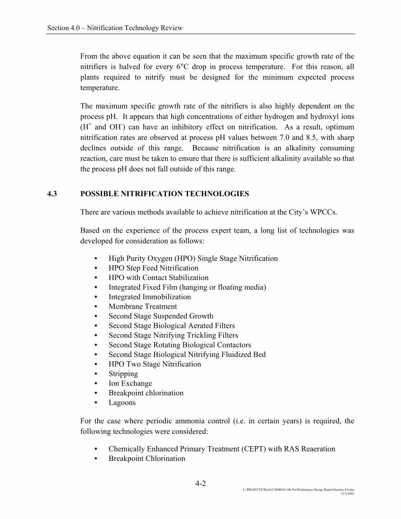
HIGH PURITY OXYGEN SINGLE STAGE NITRIFICATION (Cont’d.)
Plant Application North End The existing HPO activated sludge basins would be expanded to achieve
appropriate sludge age as required to support the ammonia limit imposed. Two key issues for nitrification implementation are (1) control of pH in the HPO basins in order to minimize nitrification inhibition, and (2) solids processing operations. Venting the last oxic cell to strip CO2 or alkalinity supplementation could be used to control pH. Since this plant processes sludge from all three WWTPs the potential for high ammonia in the centrate from dewatered digested sludge is great and needs critical consideration in the design of the liquid treatment process both with respect to aeration and alkalinity requirements.
South End The existing HPO activated sludge basins would be expanded to achieve appropriate sludge age as required to support the ammonia limit imposed. To control pH in the HPO basins to minimize nitrification inhibition may require venting the last oxic cell to strip CO2 or alkalinity supplementation.
West End Does not apply since the West End plant is conventional activated sludge.
Technical Reliability Single stage HPOAS nitrification facilities are rare because of the
complications which arise from combining HPO and nitrification, specifically pH control. Maintaining an appropriate pH in a single stage nitrifying HPOAS facility can be very tenuous due to the cumulative effects of increased carbon dioxide production from biological carbonaceous removal and of nitrification. As the CO2 content in the gas phase increases, the CO2 concentration in the wastewater increases and the system pH is depressed. Concurrently, alkalinity is consumed through the nitrification process. At a low pH (<6.5) the growth rate of the nitrifying organisms can be inhibited. To keep the system stable and reliable requires positive pH control.
Robustness Because of the sensitivity of nitrifiers and the potential for pH inhibition at a pH less than 6.5 unless there is a long SRT, the process is more susceptible to plant upset from flow and load variations.
Flexibility The process will be difficult to modify to meet changing effluent quality requirements as partial nitrification poses many operating problems. Once the process is established, changes should not be introduced except to correct process upset. Bringing basins on and off line will be complicated by the need for longer SRTs should the pH be low.
Impact on Other Parts of the Plant
The addition of nitrification would require an expansion to the existing HPOAS basin complex in order to increase the aerobic SRT to sustain nitrification. The increase in oxygen demand for nitrification may require total oxygen in excess of the current oxygen generation capacity. Additional final clarifiers may be needed depending on the resulting solids loading rate.
Space Requirements
New treatment trains could be accommodated within the site limits.
4-5 L:\PROJECTS\Wat\6234000\03\100-Pre\Preliminary Design Report\Section 4.0.doc
12/3/2002

Section 4.0 – Nitrification Technology Review
HIGH PURITY OXYGEN SINGLE STAGE NITRIFICATION (Cont’d.)
Technical (cont’d.) Expandability New treatment trains would be provided in parallel.
Constructability The construction of a new HPOAS facility would mostly be external to the existing plant and would not cause any disruption of normal plant operations. Structural requirements are not extraordinary, however, full concrete decks with insulation and cover would be required. The existing electrical service may require a major revamp to provide sufficient capacity for the additional mixers.
Operational Ease of Operation Nitrification is a sensitive process and is more susceptible to flow and load
changes than carbonaceous treatment operation because of the pH issue. Additional monitoring parameters will be required to assess plant stability.
Ease of Maintenance
Additional mechanical mixers for oxic zones would increase maintenance requirements but do not change the difficulty of maintenance.
Operator Safety No new safety concerns would arise since the processes are biological. If chemical addition is required for alkalinity supplementation this could result in some additional safety issues depending on the chemical used.
Operator Environment
No change from existing operations.
Environmental and Aesthetic Traffic There is no difference in traffic associated with this option.
Noise Operating equipment is similar to existing equipment in wastewater treatment plants. There would be no substantial impact.
Visual Aeration basins are underground and covered similar to existing tanks. Architectural finishes would be compatible and thus, would cause minimal impacts.
Odours With covered basins no odours are anticipated. Odours have not traditionally been a problem with anaerobic and anoxic zones at other plants.
4-6 L:\PROJECTS\Wat\6234000\03\100-Pre\Preliminary Design Report\Section 4.0.doc
12/3/2002

Section 4.0 – Nitrification Technology Review
HPO Step Feed Description Step Feed activated sludge systems are a modification to conventional plug
flow activated sludge processes. In this configuration primary effluent is discharged at a range of locations along the oxygen reactor. The step feed approach can be used to maintain a higher percentage of the biosolids in the upstream portion of the reactor. This lowers the downstream solids concentration and reduces the solids load on the secondary clarifiers, ensuring that clarifier performance is not compromised. As a result, step feed systems can be operated at higher SRTs than conventional systems, and can establish nitrification in smaller basins. When storm flows occur, the step feed configuration protects the large biomass inventory in the upstream stages of the reactor, preventing washout. Where combined nitrification and nitrogen removal are to be considered, alternating anoxic and aerobic zones are provided with the primary effluent always fed to the anoxic zones. This configuration provides a degree of CO2 stripping and alkalinity recovery in the anoxic zones so that the pH of the bioreactor is maintained in an acceptable range for nitrification.
RASTO CLARIFIERS
RAS
ANOXICCELL NO. 1
PURE OXYGENCELL NO. 1
MLSS6000 mg/L
5% FLOW 15% FLOW 20% FLOW 10% FLOW5% FLOW 15% FLOW 20% FLOW 10% FLOW
MLSS6000 mg/L
MLSS5000 mg/L
MLSS5000 mg/L
MLSS3000 mg/L
MLSS3000 mg/L
MLSS3000 mg/L
MLSS3000 mg/L
PURE OXYGEN CELL NO. 2
PURE OXYGEN CELL NO. 3
PURE OXYGEN CELL NO. 4
PURE OXYGEN CELL NO. 7
PURE OXYGEN CELL NO. 6
PURE OXYGENCELL NO. 5
PURE OXYGEN CELL NO. 8
ANOXICCELL NO. 5
ANOXICCELL NO. 2
ANOXICCELL NO. 3
ANOXICCELL NO. 4
ANOXICCELL NO. 8
ANOXICCELL NO. 7
ANOXICCELL NO. 6
INFLUENT
STEP FEED BIOREACTOR CONFIGURATION
Effluent Quality Limits Step feed systems can be tailored to meet varying effluent parameters. Preliminary analysis based on the City’s wastewater characteristics indicate that a 2.5 to 3.5 hour hydraulic retention time (HRT) is needed to meet an effluent ammonia concentration of 10 mg/L, 3.5 to 4.5 hour HRT to meet 5 mg/L, and 6.0 to 7.0 hour HRT to meet 2 mg/L. As with any biological system, temperature affects nitrification, and can result in a reduction in ammonia removal during winter months or spring runoff.
4-7 L:\PROJECTS\Wat\6234000\03\100-Pre\Preliminary Design Report\Section 4.0.doc
12/3/2002

Section 4.0 – Nitrification Technology Review
HPO Step Feed (Cont’d.)
Wastewater Treatment Plant Specific Considerations At the NEWPCC the existing six HPO reactors could be configured to four step feed trains complete with anoxic zones. The six HPO reactors would be segregated into two trains each with three HPO reactors. The three parallel HPO reactors would be converted to two step feed trains. The covers would be removed from the central module and a central dividing wall and primary effluent distribution channel constructed along its central axis. Four anoxic basins would be formed on both sides of the wall, parallel to the adjoining stages of the HPO basins. Similarly, at the SEWPCC three of the existing HPO reactors would be converted to two step feed trains. An anoxic module would be constructed for the fourth HPO reactor, giving a total of three complete step feed trains. At the WEWPCC step feed can be achieved by converting the two existing completely mixed conventional aeration reactors into two step feed modules.
Technical Reliability Step feed is a common arrangement for larger, conventional activated sludge
facilities. However, this specific arrangement has not been used in an HPO plant in the past.
Robustness The step feed system is less susceptible to plant upset from flow and load variations. The impact from these variations are minimized by distributing the primary effluent to various points through the length of the bioreactor. By distributing the load through the basin, oxygen requirements are equalized, minimizing the risks of low dissolved oxygen concentrations in the upstream end of the reactors.
Flexibility This system offers a higher degree of flexibility than conventional activated sludge processes. The distribution of primary effluent throughout the step feed basin can be varied seasonally and tailored to provide optimized results for each WWTP.
Impact on Other Parts of the Plant
The increase in oxygen demand for nitrification may require total oxygen in excess of the current oxygen generation capacity. The anoxic zones would be uncovered to allow CO2 stripping. Removal of the cover may generate problems due to cold weather, odour control and fog generation. The existing electrical system may require upgrading to accommodate the additional pumping requirements.
Space Requirements
New treatment works would be accommodated within the existing facility.
Expandability This process can be expanded as required to suit future flows by adding additional bioreactors.
Constructability Structural modifications would be required within the existing bioreactors and would temporarily disrupt normal operations. The work could be done in stages to maintain partial plant capacity through the construction period.
Operational Ease of Operation Nitrification is more sensitive than carbonaceous treatment. Additional
monitoring will be required to assess plant stability. Primary effluent flow splits to the various stages are critical and may involve greater operator attention to achieve process optimization.
4-8 L:\PROJECTS\Wat\6234000\03\100-Pre\Preliminary Design Report\Section 4.0.doc
12/3/2002

Section 4.0 – Nitrification Technology Review
HPO Step Feed (Cont’d.)
Operational (cont’d.) Ease of Maintenance
Additional pumps would increase maintenance requirements but do not change the difficulty of maintenance.
Operator Safety No new safety concerns would arise since the processes are biological. If chemical addition is required for alkalinity supplementation this could result in some additional safety issues depending on the chemical used.
Operator Environment
No change from existing operations.
Environmental and Aesthetic Traffic There is no difference in traffic associated with this option.
Noise Operating equipment is similar to existing equipment in wastewater treatment plants. There would be no substantial impact.
Visual There would be no significant visual impact.
Odours The anoxic zones would be uncovered to allow CO2 stripping. This may generate additional odour control requirements however, odour has not traditionally been a problem with anoxic zones at other plants.
4-9 L:\PROJECTS\Wat\6234000\03\100-Pre\Preliminary Design Report\Section 4.0.doc
12/3/2002
Section 4.0 – Nitrification Technology Review
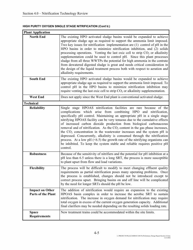
High Purity Oxygen with Contact Stabilization Nitrification Description High purity oxygen with contact stabilization for nitrification utilizes a
variation of the contact stabilization technology to achieve complete nitrification in a much reduced aerobic volume. Return activated sludge (RAS) combines with ammonia rich sidestreams in an aerated basin to allow nitrification of the sidestreams prior to the aeration basins. Nitrification of the influent ammonia occurs in the pure oxygen basins but at a much reduced in-basin sludge age. Total sludge age of the RAS reaeration basin plus the HPO basins meets minimum nitrification requirements in less overall tank volume, due to high solids concentration and detention time in the reaeration basin. Using the RAS reaeration for nitrification allows constant reseeding of nitrifying organisms to the HPO basins. The key to the success of the nitrification process is pH control in the HPO basins in order to prevent nitrification inhibition. Inhibition impacts in the HPO process will carry over to the reaeration basin. Venting the last oxic cell in the HPO basin to allow CO2 stripping or alkalinity addition to buffer against pH depression due to CO2 buildup and alkalinity consumption from nitrification have been successful control measures. Even if CO2 stripping is used, additional alkalinity may be required to compensate for alkalinity consumed through nitrification.
RELIEFVALVE
VENT GASRELIEFVALVE
OXYGENSUPPLY
SECONDARY CLARIFIER
PRIMARYEFFLUENT
REAERATION
CENTRATE
RAS CONTACT STABILIZATION NITRIFICATION SCHEMATIC
Level of Control Ammonia To achieve year round effluent ammonia concentrations of 2 or 5 mg/L will
require longer SRTs and thus larger reaeration basins than required with seasonal nitrification requirements. If the ammonia limit of 2 or 5 mg/L is seasonal and only applied to the summer and fall, nitrification can be established following spring runoff and then eliminated in winter. To prevent nitrification during the winter and spring, RAS would bypass reaeration and feed directly into the HPO basins. For ammonia concentrations of 10 or 15 mg/L split treatment would be used. For this process only a portion of the HPO basins would be coupled with RAS reaeration basins for nitrification. Effluent from the nitrification trains would be blended with the effluent from the carbonaceous treatment trains to meet the effluent goals.
4-10 L:\PROJECTS\Wat\6234000\03\100-Pre\Preliminary Design Report\Section 4.0.doc
12/3/2002

Section 4.0 – Nitrification Technology Review
High Purity Oxygen with Contact Stabilization Nitrification (Cont’d.)
Plant Application North End The existing HPO activated sludge basins and clarifiers would not be expanded;
however new reaeration tanks would be constructed to aerate RAS and centrate from dewatering. Since this plant processes sludge from all three WWTPs the potential for high ammonia in the centrate from dewatered digested sludge is great and should provide sufficient ammonia to support nitrification in the reaeration basins. This would off load a significant ammonia load from the HPO basins. Alkalinity supplementation will need to be evaluated.
South End Does not apply since there are no ammonia rich sidestreams at the SEWPCC.
West End Does not apply since the West End plant is conventional activated sludge and there are no ammonia rich sidestreams.
Technical Reliability Single stage HPOAS nitrification facilities are rare because of the
complications which arise from combining HPO and nitrification, specifically pH control. Maintaining an appropriate pH in a single stage nitrifying HPOAS facility can be very tenuous due to the cumulative effects of increased carbon dioxide production from biological carbonaceous removal and of nitrification. As the CO2 content in the gas phase increases, the CO2 concentration in the wastewater increases and the system pH is depressed. Concurrently, alkalinity is consumed through the nitrification process. At a low pH (<6.5) the growth rate of the nitrifying organisms can be inhibited. To keep the system stable and reliable requires positive pH control through venting or alkalinity supplementation. The addition of the RAS nitrification reaeration basin will provide process stability through the high concentration of nitrifying organisms maintained in the basin. In addition, a significant amount of ammonia variation which can occur from solids processing is kept out of the mainstream HPO basins thus minimizing load variation.
Robustness Because of the sensitivity of nitrifiers and the potential for pH inhibition, a single stage nitrifying HPO activated sludge process is more susceptible to upset from flow and load variations. However, since a majority of the nitrifying organism population is maintained in the reaeration basin, the potential for washout is greatly reduced. In addition, the ammonia load from solids processing will be treated in the reaeration basins; thus, load variation to the HPO basins is also reduced.
Flexibility The process will be difficult to modify to meet changing effluent quality requirements as partial nitrification poses many operating problems. Once the process is established, changes should not be introduced except to correct process upset. Partial RAS reaeration would not be feasible, therefore, if multiple HPO basins are serviced from a common RAS line, all basins tied to that RAS system would be part of the nitrification process.
4-11 L:\PROJECTS\Wat\6234000\03\100-Pre\Preliminary Design Report\Section 4.0.doc
12/3/2002

Section 4.0 – Nitrification Technology Review
High Purity Oxygen with Contact Stabilization Nitrification (Cont’d.)
Technical (cont’d.) Impact on Other Parts of the Plant
To add nitrification would require new reaeration basins to nitrify ammonia rich sidestream. The existing HPO complex would not be expanded. With this alternative, there would be no impact on the main liquid treatment plant hydraulics since the reaeration basins are off line. The increase in oxygen demand for nitrification could be provided by conventional aeration equipment with blowers or if sufficient oxygen generation capacity is available, pure oxygen could be used.
Space Requirements
New reaeration basins could be accommodated within the site limits.
Expandability Easily expanded by increasing RAS reaeration if split treatment used, or adding new parallel treatment trains for complete nitrification of the entire plant flow.
Constructability The construction of new reaeration basins would be external to the existing plant and would cause only minimal disruption of normal plant operations. The key issue will be re-piping the RAS through the reaeration basins. Structural requirements are not extraordinary.
Operational Ease of Operation The off-line nitrification process will simplify nitrification requirements
provided solids processing is a daily operation. Intermittent operation, i.e. no weekend or holiday operations, could pose problems for nitrification. Additional monitoring parameters and points will be required to assess plant stability with venting or alkalinity supplementation.
Ease of Maintenance
Additional aeration equipment would increase maintenance requirements but would not change the difficulty of maintenance.
Operator Safety No new safety concerns would arise since the processes are biological. If chemical addition is required for alkalinity supplementation, this could result in some additional safety issues depending on the chemical used.
Operator Environment
No change from existing operations.
Environmental and Aesthetic Traffic There is no difference in traffic associated with this option.
Noise Operating equipment is similar to existing equipment in wastewater treatment plants. There would be no substantial impact.
Visual Aeration basins are underground and covered similar to existing tanks. Architectural finishes would be compatible and thus, would cause minimal impacts.
Odours Off gasses from CO2 stripping could potentially increase emissions from the bioreactor. However, these types of emissions are not usually associated with odour complaints. If this option is included for further consideration, then a detail analysis of the off gas stream should be conducted.
4-12 L:\PROJECTS\Wat\6234000\03\100-Pre\Preliminary Design Report\Section 4.0.doc
12/3/2002

Section 4.0 – Nitrification Technology Review
Integrated Fixed Film Activated Sludge – Hanging Fixed Media Description Hanging fixed media IFAS systems incorporate rope-like media attached to
metal brackets that in turn are mounted on a metal framework. The completed metal framework is a modular unit that can be immersed in the aerobic zone of a bioreactor. The media are fabricated from polyvinyl chloridine (PVCE) filaments woven into rope-like strands with protruding ~5mm loops. The basic concept is to provide surfaces on which microorganisms can grow to effectively increase the SRT of an activated sludge treatment system and thus improve the nitrification performance of the system. Trade names include Ringlace and Biomatrix. Typical mean media density is about 120 lineal m/m3 based on the entire bioreactor volume.
Initially used in Japan and Germany, the technology was first applied in North America at the Annapolis, Maryland plant in the early 1990’s and since has been the subject of considerable research and development work at this plant as well as at others in the U.S. Northeast and in Southern Ontario. The technical literature reports ammonia removal as varying from ~0.4 kg/d/1000 lineal meters of rope at 10°C to ~1.7 kg/d/1000 m at 15°C.
PHOTOGRAPH OF TWO HANGING FIXED MEDIA IFAS MODULES INSTALLED IN A BIOREACTOR AT THE WATERDOWN, ONTARIO WWTP
Level of Control Hanging fixed film IFAS technology is perhaps better suited for installation in existing high rate activated sludge systems that must achieve an intermediate level of ammonia removal rather than in systems that must achieve very low effluent ammonia concentrations. Achieving low effluent ammonia concentrations in an activated sludge system requires that the system be operated at a relatively low F:M loading and long SRT. Under such operating conditions, little biomass develops on the media.
4-13 L:\PROJECTS\Wat\6234000\03\100-Pre\Preliminary Design Report\Section 4.0.doc
12/3/2002
Section 4.0 – Nitrification Technology Review
Integrated Fixed Film Activated Sludge – Hanging Fixed Media (Cont’d.)
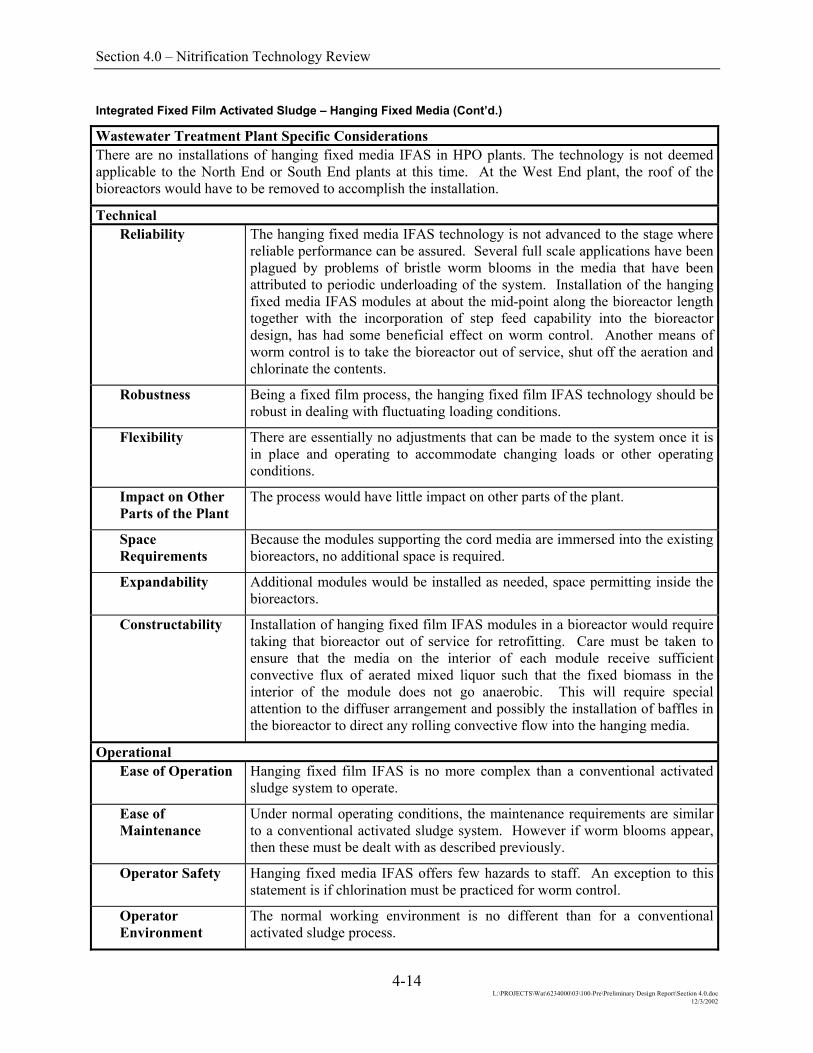
Wastewater Treatment Plant Specific Considerations There are no installations of hanging fixed media IFAS in HPO plants. The technology is not deemed applicable to the North End or South End plants at this time. At the West End plant, the roof of the bioreactors would have to be removed to accomplish the installation.
Technical Reliability The hanging fixed media IFAS technology is not advanced to the stage where
reliable performance can be assured. Several full scale applications have been plagued by problems of bristle worm blooms in the media that have been attributed to periodic underloading of the system. Installation of the hanging fixed media IFAS modules at about the mid-point along the bioreactor length together with the incorporation of step feed capability into the bioreactor design, has had some beneficial effect on worm control. Another means of worm control is to take the bioreactor out of service, shut off the aeration and chlorinate the contents.
Robustness Being a fixed film process, the hanging fixed film IFAS technology should be robust in dealing with fluctuating loading conditions.
Flexibility There are essentially no adjustments that can be made to the system once it is in place and operating to accommodate changing loads or other operating conditions.
Impact on Other Parts of the Plant
The process would have little impact on other parts of the plant.
Space Requirements
Because the modules supporting the cord media are immersed into the existing bioreactors, no additional space is required.
Expandability Additional modules would be installed as needed, space permitting inside the bioreactors.
Constructability Installation of hanging fixed film IFAS modules in a bioreactor would require taking that bioreactor out of service for retrofitting. Care must be taken to ensure that the media on the interior of each module receive sufficient convective flux of aerated mixed liquor such that the fixed biomass in the interior of the module does not go anaerobic. This will require special attention to the diffuser arrangement and possibly the installation of baffles in the bioreactor to direct any rolling convective flow into the hanging media.
Operational Ease of Operation Hanging fixed film IFAS is no more complex than a conventional activated
sludge system to operate.
Ease of Maintenance
Under normal operating conditions, the maintenance requirements are similar to a conventional activated sludge system. However if worm blooms appear, then these must be dealt with as described previously.
Operator Safety Hanging fixed media IFAS offers few hazards to staff. An exception to this statement is if chlorination must be practiced for worm control.
Operator Environment
The normal working environment is no different than for a conventional activated sludge process.
4-14 L:\PROJECTS\Wat\6234000\03\100-Pre\Preliminary Design Report\Section 4.0.doc
12/3/2002

Section 4.0 – Nitrification Technology Review
Integrated Fixed Film Activated Sludge – Hanging Fixed Media (Cont’d.)
Environmental and Aesthetic Traffic The process would have no impact on traffic.
Noise The process would have no impact on noise levels.
Visual The hanging media are submerged in the bioreactor and thus are not visible under normal operation.
Odours Odour emissions would be similar to a conventional activated sludge process.
4-15 L:\PROJECTS\Wat\6234000\03\100-Pre\Preliminary Design Report\Section 4.0.doc
12/3/2002

Section 4.0 – Nitrification Technology Review
Integrated Fixed Film Activated Sludge – Free Floating Media Description Free floating media IFAS technology employs small pieces of sponge cuboids
or rigid plastic rings that are essentially neutrally-buoyant and have a high surface area per unit volume of media. The media are added to a bioreactor and maintained in suspension by the mixing action therein. Microbial growth attaches to the surfaces of the media and thus an increase in biomass, and hence SRT, occurs.
Typically, the sponge cuboids are ~7.5 mL in volume with individual surface areas of ~25 cm2. Pore sizes are nominally 0.6 mm. The rigid plastic ring media consist of open cylinders approximately 22 mm diameter and 15 mm long with internal webbing to provide additional surface area. For combined carbonaceous removal and nitrification, the bulk media volume typically occupies 10 to 30 percent of the bioreactor volume.
Operating experience indicates that biomass growth on the sponge media has to be controlled continuously. This is accomplished by an air lift pump and washing system. Excessive biomass accumulations do not appear to be a problem with the rigid plastic media.
ON THE LEFT IS A PHOTOGRAPH OF FREE-FLOATING RIGID PLASTIC MEDIA (two pieces with biomass taken from an operating bioreactor and two clean pieces).
ON THE RIGHT IS A PHOTOGRAPH OF A BIOREACTOR WITH SUCH MEDIA IN OPERATION
Level of Control Full scale applications of free-floating media have demonstrated the ability of the technology to achieve treated effluent NH3-N concentrations of <2 mg/L during winter operation at 10 °C. However it is recommended that pilot and/or full-scale demonstration study be done to assist in the design of a site-specific system.
4-16 L:\PROJECTS\Wat\6234000\03\100-Pre\Preliminary Design Report\Section 4.0.doc
12/3/2002

Section 4.0 – Nitrification Technology Review
Integrated Fixed Film Activated Sludge – Free Floating Media (Cont’d.)
Wastewater Treatment Plant Specific Considerations At the West End plant, the media would be added directly to the bioreactors. A screen placed at the outlet of each bioreactor would prevent the media from passing into the final clarifiers.
We are not aware of any application of free floating IFAS media in mechanical aeration systems. It is suspected that the media would be fractured or rapidly abraded in such systems unless it were contained in “cages” to prevent contact with the rotating impellers of the aeration equipment. Alternately the media could be fabricated from a stronger material better able to resist the impact of the aeration equipment.
Technical Reliability The free-floating IFAS media have generally shown more reliable and trouble-
free performance than the hanging fixed media IFAS systems. Nevertheless as noted previously, it would be prudent to conduct a site-specific pilot study prior to committing to a full-plant retrofit with such media.
Robustness Being a fixed film process, the free floating IFAS media technology should be robust in dealing with fluctuating loading conditions.
Flexibility There are essentially no adjustments that can be made to the system once it is in place and operating, other than to add more media, to accommodate changing loads or other operating conditions.
Impact on Other Parts of the Plant
The process would have little impact on other parts of the plant.
Space Requirements
Because the media would be added to and suspended in the existing bioreactors, no additional space is required.
Expandability Additional media could be added to the bioreactors, as long as the media density did not interfere with mixing conditions and as long as the aeration system could meet the demand of the extra biomass that would grow.
Constructability No particular construction problems would be anticipated if free floating IFAS media were used at the West End plant. However at the North End and South End plants, the bioreactor covers would require removal in order to gain access to install the “cage” media retention structures mentioned previously, unless a stronger media could be supplied that is capable of withstanding the impacts of the rotating aeration equipment without disintegration.
Operational Ease of Operation A free floating fixed IFAS system is no more complex than a conventional
activated sludge system to operate.
Ease of Maintenance
In normal operation, the technology would be no more difficult to maintain than is a conventional activated sludge system. However should a bioreactor require removal from service for hands-on maintenance to the aeration equipment, the media may require removal from the bioreactor in order to gain unhampered access to the aeration diffusers. This could be accomplished by means of a vacuum truck and/or a recessed impeller type of pump.
4-17 L:\PROJECTS\Wat\6234000\03\100-Pre\Preliminary Design Report\Section 4.0.doc
12/3/2002
Section 4.0 – Nitrification Technology Review
Integrated Fixed Film Activated Sludge – Free Floating Media (Cont’d.)
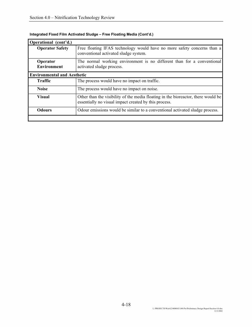
Operational (cont’d.) Operator Safety Free floating IFAS technology would have no more safety concerns than a
conventional activated sludge system.
Operator Environment
The normal working environment is no different than for a conventional activated sludge process.
Environmental and Aesthetic Traffic The process would have no impact on traffic.
Noise The process would have no impact on noise.
Visual Other than the visibility of the media floating in the bioreactor, there would be essentially no visual impact created by this process.
Odours Odour emissions would be similar to a conventional activated sludge process.
4-18 L:\PROJECTS\Wat\6234000\03\100-Pre\Preliminary Design Report\Section 4.0.doc
12/3/2002

Section 4.0 – Nitrification Technology Review
Integrated Immobilization Description Integrated immobilization involves adding polymeric cubes, approximately
3 mm square, to the bioreactor. These cubes are impregnated with nitrifying organisms, which in theory, allow the heterotrophic carbonaceous bacteria and the autotrophic nitrifying bacteria to be separated into two distinct cultures. Selected wasting of the carbonaceous bacteria can be conducted leaving an increased population of nitrifying bacteria. The increased population allows a higher level of ammonia removal without additional bioreactor volume. The impregnated cubes are retained in the mixed liquor by screens with 1.5 to 2.0 mm openings.
RAS
PRIMARYEFFLUENT
MEDIA CUBES DIFFUSER DISKS
TO SECONDARY CLARIFIER ANOXIC
ZONE
INTEGRATED IMMOBILIZATION
Level of Control Literature results of pilot testing indicate a wide range of acceptable loading rates required to achieve effluent ammonia concentrations less than 2 mg/L. It would appear that median loading rates in the order of 0.3 kgN/m3/d are required at a wastewater temperature of 23°C. Based on this loading rate two additional HPO reactors would be required at the NEWPCC and four additional HPO reactors at the SEWPCC. To confirm whether higher loading rates can be achieved, studies are required to determine the specific performance characteristics at each plant. One pilot study found that treatment of an industrial wastewater at a loading rate as low as 0.2 kgN/m3/d could not reduce effluent ammonia concentrations below 10 mg/L.
4-19 L:\PROJECTS\Wat\6234000\03\100-Pre\Preliminary Design Report\Section 4.0.doc
12/3/2002

Section 4.0 – Nitrification Technology Review
Integrated Immobilization (Cont’d.)
Plant Applications At the NEWPCC, the existing HPO reactors would be retrofitted to strip CO2 from the headspace of the reactors. New aerators would likely be required to prevent damage to the immobilized media. Based on the information available, a minimum of two additional HPO reactors would be required. Similar modifications to the SEWPCC aeration system would be required, with an additional four HPO reactors. The WEWPCC would not require CO2 stripping, as it is a conventional air activated sludge plant. The existing tankage at the WEWPCC would be sufficient to maintain effluent ammonia concentrations below 2 mg/L.
Technical Reliability This process was first reported in the early 1990’s and has been demonstrated
at relatively small scale in several plants. No installations have been reported where this technology has been used in HPO reactors. To alleviate the inhibitory effect of pH on the process it is likely that CO2 stripping would have to be incorporated. Based on the available information, the reliability of the integrated immobilization process would have to be confirmed at pilot scale prior to full scale design.
Robustness The nitrifiers present in the immobilized gel provides a continuous seed to the plant and ensures quick recovery from any surge or toxic shock loading. This process offers some promise; however, potential problems may include damage to the media during mixing.
Flexibility This process has a certain degree of flexibility as media can be introduced to the bioreactor as needed.
Impact on Other Parts of the Plant
To implement this process, additional HPO reactors and modifications to the existing basins would be required. These would likely include CO2 stripping and modifications to the mixing apparatus.
Space Requirements
One main advantage of this alternative, is that it requires less space than conventional treatment processes. The space requirement can be accommodated at all three of the City’s wastewater treatment plant sites.
Expandability New treatment trains could be added in parallel as needed.
Constructability The construction of additional trains would mostly be off-line and would not cause any disruption of normal plant operations. Structural requirements are not extraordinary.
Operational Ease of Operation Facility operation would be similar to the existing process. Additional testing
and monitoring of the process would be required to ensure that the conditions for nitrification are maintained.
Ease of Maintenance
Regular cleaning of screens is required to dislodge any particles and debris caught in the mesh. Additional mechanical mixers in the anoxic zones would be required, increasing the time required for maintenance purposes.
4-20 L:\PROJECTS\Wat\6234000\03\100-Pre\Preliminary Design Report\Section 4.0.doc
12/3/2002
Section 4.0 – Nitrification Technology Review
Integrated Immobilization (Cont’d.)
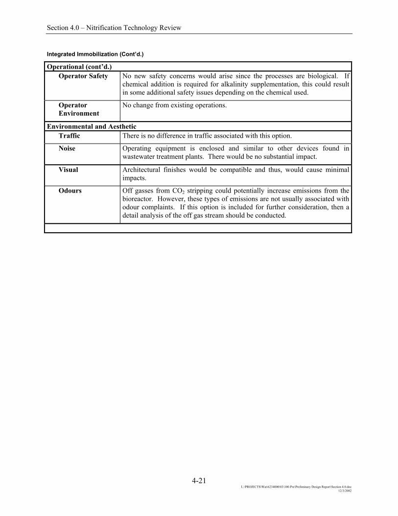
Operational (cont’d.) Operator Safety No new safety concerns would arise since the processes are biological. If
chemical addition is required for alkalinity supplementation, this could result in some additional safety issues depending on the chemical used.
Operator Environment
No change from existing operations.
Environmental and Aesthetic Traffic There is no difference in traffic associated with this option.
Noise Operating equipment is enclosed and similar to other devices found in wastewater treatment plants. There would be no substantial impact.
Visual Architectural finishes would be compatible and thus, would cause minimal impacts.
Odours Off gasses from CO2 stripping could potentially increase emissions from the bioreactor. However, these types of emissions are not usually associated with odour complaints. If this option is included for further consideration, then a detail analysis of the off gas stream should be conducted.
4-21 L:\PROJECTS\Wat\6234000\03\100-Pre\Preliminary Design Report\Section 4.0.doc
12/3/2002
Section 4.0 – Nitrification Technology Review
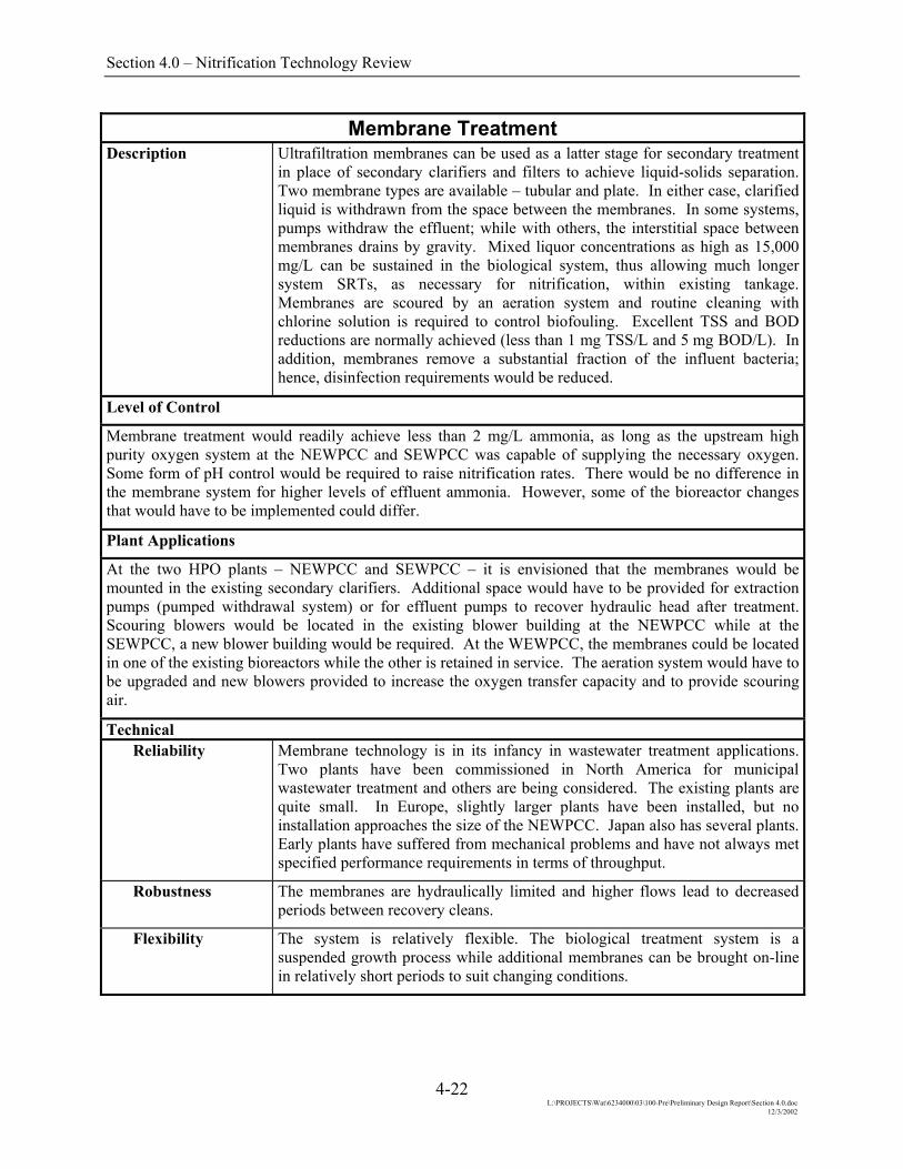
Membrane Treatment Description Ultrafiltration membranes can be used as a latter stage for secondary treatment
in place of secondary clarifiers and filters to achieve liquid-solids separation. Two membrane types are available – tubular and plate. In either case, clarified liquid is withdrawn from the space between the membranes. In some systems, pumps withdraw the effluent; while with others, the interstitial space between membranes drains by gravity. Mixed liquor concentrations as high as 15,000 mg/L can be sustained in the biological system, thus allowing much longer system SRTs, as necessary for nitrification, within existing tankage. Membranes are scoured by an aeration system and routine cleaning with chlorine solution is required to control biofouling. Excellent TSS and BOD reductions are normally achieved (less than 1 mg TSS/L and 5 mg BOD/L). In addition, membranes remove a substantial fraction of the influent bacteria; hence, disinfection requirements would be reduced.
Level of Control
Membrane treatment would readily achieve less than 2 mg/L ammonia, as long as the upstream high purity oxygen system at the NEWPCC and SEWPCC was capable of supplying the necessary oxygen. Some form of pH control would be required to raise nitrification rates. There would be no difference in the membrane system for higher levels of effluent ammonia. However, some of the bioreactor changes that would have to be implemented could differ.
Plant Applications
At the two HPO plants – NEWPCC and SEWPCC – it is envisioned that the membranes would be mounted in the existing secondary clarifiers. Additional space would have to be provided for extraction pumps (pumped withdrawal system) or for effluent pumps to recover hydraulic head after treatment. Scouring blowers would be located in the existing blower building at the NEWPCC while at the SEWPCC, a new blower building would be required. At the WEWPCC, the membranes could be located in one of the existing bioreactors while the other is retained in service. The aeration system would have to be upgraded and new blowers provided to increase the oxygen transfer capacity and to provide scouring air.
Technical Reliability Membrane technology is in its infancy in wastewater treatment applications.
Two plants have been commissioned in North America for municipal wastewater treatment and others are being considered. The existing plants are quite small. In Europe, slightly larger plants have been installed, but no installation approaches the size of the NEWPCC. Japan also has several plants. Early plants have suffered from mechanical problems and have not always met specified performance requirements in terms of throughput.
Robustness The membranes are hydraulically limited and higher flows lead to decreased periods between recovery cleans.
Flexibility The system is relatively flexible. The biological treatment system is a suspended growth process while additional membranes can be brought on-line in relatively short periods to suit changing conditions.
4-22 L:\PROJECTS\Wat\6234000\03\100-Pre\Preliminary Design Report\Section 4.0.doc
12/3/2002

Section 4.0 – Nitrification Technology Review
Membrane Treatment (Cont’d.)
Impact on Other Parts of the Plant
The existing bioreactors would have to be reconfigured to allow nitrification. WAS would be withdrawn at a concentration of 12,000 to 15,000 mg/L, directly from the bioreactor. At the increased concentration, less thickening would be required.
Space Requirements
Minimal additional space would be required at any of the plants to facilitate membrane treatment.
Expandability This process can be expanded to suit additional flows by adding more membranes. The practical limit would be a function of the bioreactor capacity. The bioreactors could be modified to achieve nitrogen removal and phosphorus removal.
Constructability The membrane system would be installed within the existing plant and would interfere with operations.
Operational Ease of Operation Membrane systems are difficult to operate due to the interaction of flux,
transmembrane pressure, recovery cleaning schedules, and mixed liquor fluctuations.
Ease of Maintenance
Recovery cleaning is a manually intensive operation and would be required on a frequent basis. Debris occasionally must be cleaned from the membranes by hand.
Operator Safety The use of chlorine solutions for cleaning adds to the plant hazards due to the presence of this chemical.
Operator Environment
The working environment does not differ from a conventional activated sludge plant.
Environmental and Aesthetic Traffic There is no difference in traffic associated with this option.
Noise Operating equipment is enclosed and similar to other devices found in wastewater treatment plants. There would be no substantial impact.
Environmental and Aesthetic (cont’d.) Visual The majority of the modifications would be located within the existing
structures. Minor additions at the SEWPCC would not create any visual impact.
Odours Odours would be no different than those emanating from a conventional activated sludge facility.
4-23 L:\PROJECTS\Wat\6234000\03\100-Pre\Preliminary Design Report\Section 4.0.doc
12/3/2002

Section 4.0 – Nitrification Technology Review
Second Stage Suspended Growth Description This process is essentially two activated sludge plants in series. The first stage
is aggressively designed and operated as a high rate system for carbonaceous removal only while the second stage is designed and operated at a lower rate for ammonia oxidation. Because the net yield of autotrophic (nitrifying) microorganisms is low compared to heterotrophic organisms, the MLSS concentration in the second stage bioreactor is often difficult to maintain unless there is a significant BOD and TSS breakthrough from the high rate fist stage system and/or a fraction of the secondary influent is step fed to the second stage.
Some of the earliest activated sludge plant nitrification upgrades in North America were second stage additions to an original high rate carbonaceous removal plant. Accordingly the technology is mature, although more recent developments have been to use single stage systems or second stage fixed media systems because of cost and/or space considerations.
BIOREACTOR 1 BIOREACTOR 2CLARIFIER 1 CLARIFIER 2
RAS 2
WAS 1 WAS 2
STEP FEEDCAPABILITY
PRIMARYEFFLUENT
TREATEDEFFLUENT
RAS 1
BLOCK DIAGRAM SCHEMATIC OF A SECOND STAGE SUSPENDED GROWTH NITRIFICATION SYSTEM
Level of Control The second stage suspended growth technology is capable of achieving relatively low levels of treated effluent ammonia nitrogen concentrations to below 2 mg/L.
Wastewater Treatment Plant Specific Considerations There would be space constraints at the North End plant to install a second stage section. There is sufficient space to accommodate a second stage at the South End and West End plants; however, the former would require an intermediate pumping station. It may be possible to reconfigure the three Winnipeg plants by placing certain existing bioreactor and clarifier tankage in series to operate as a two-stage suspended growth system. An intermediate lift station and appropriate piping would be required to pump treated effluent from one stage to another. While additional secondary treatment tankage likely would be required to maintain plant capacities, such a reconfiguration could reduce the need for a complete doubling of secondary treatment tankage. However it would be at the expense of a more complicated plant arrangement.
4-24 L:\PROJECTS\Wat\6234000\03\100-Pre\Preliminary Design Report\Section 4.0.doc
12/3/2002
Section 4.0 – Nitrification Technology Review
Second Stage Suspended Growth (Cont’d.)
Technical Reliability The second stage suspended growth nitrification technology is quite mature and
can be designed and operated to reliably meet relatively low treated effluent ammonia standards.
Robustness The tanks-in-series nature of the process serves to dampen diurnal loading variations somewhat, thereby making the process better able to handle loading fluctuations than a single stage system. The independent control of SRT in the two stages also adds a degree of robustness as well.
Flexibility The step feed capability and the independent control of SRT in each stage provides operational flexibility to cope with loading changes as well as seasonal temperature variations.
Impact on Other Parts of the Plant
There would be little impact on other parts of the plant by the implementation of a second stage suspended growth process.
Space Requirements
The addition of a second stage would essentially mean a doubling of the secondary section of each plant.
Expandability Future increases in flows and loads would be accommodated by the addition of more bioreactor and clarifier tankage. As noted previously, there may be significant space constraints at the North End plant site in this regard.
Constructability The construction of new second stage tankage would be relatively straightforward and be similar to the construction of an additional secondary treatment system, albeit one that would incorporate an interim pumping station. Retrofitting existing tankage in a series configuration would be more problematic, having to construct an intermediate pumping station, a forcemain and a secondary influent step feed capability.
Operational Ease of Operation Operation of a second stage suspended growth system is inherently more
complex due to the need to control two independent activated sludge systems and the step feed of secondary influent to the second stage.
Ease of Maintenance
There will be additional equipment to maintain, including a duplicate of what is required for a single stage system and the pumping system for the intermediate pumping stage.
Operator Safety Safety issues would be similar to those already occurring at the three Winnipeg plants.
Operator Environment
The normal working environment would be little different than for a conventional activated sludge process, other than the need to monitor and control the operation of two similar process stages rather than only one.
Environmental and Aesthetic Traffic The process would have little impact on traffic.
Noise The process would have little impact on noise.
4-25 L:\PROJECTS\Wat\6234000\03\100-Pre\Preliminary Design Report\Section 4.0.doc
12/3/2002

Section 4.0 – Nitrification Technology Review
Second Stage Suspended Growth (Cont’d.)
Environmental and Aesthetic (cont’d.) Visual Additional bioreactor and clarifier tankage would have a similar appearance to
existing tankage on the treatment plant site. Likewise for an intermediate pumping system.
Odours Odour emissions would be similar to a conventional activated sludge process.
4-26 L:\PROJECTS\Wat\6234000\03\100-Pre\Preliminary Design Report\Section 4.0.doc
12/3/2002

Section 4.0 – Nitrification Technology Review
Second Stage Biological Aerated Filter (BAF) Description BAF is similar to potable water rapid filtration, except that the media is
constantly aerated. It can be operated either in downflow (counter current) or in upflow (co-current) modes, with either heavier-than-water or lighter-than-water media. The following diagram shows the more common upflow arrangement. The filters are backwashed regularly, the frequency depending on the loading. When used for second stage nitrification, backwashing is required about once per week. Backwash waste is directed to sludge management. No secondary clarifiers are needed due to the filtering action of the media. The size of the modules are generally limited to about 100 m2.
UPFLOW BAF SCHEM Level of Control BAF design can be tailored to meet varying effluent parameteBOD removal, to achieve an effluent ammonia concentration oas high as 1.0 to 1.5 kgNH3-N/m3/d. The design loading cconcentration is relaxed. At an effluent standard of 10 mgNH3 to 4.5 kgNH3-N/m3/d. Alternatively, split stream treatmentammonia levels. Wastewater temperature affects nitrificattemperatures, the loadings must be reduced to as low as 60 pemaintain performance.
Plant Applications BAFs are relatively compact, so would fit within the spacespecific constraints would apply to this option. The centrateequalized or separately treated to ensure that the contributioflows did not cause erratic performance.
PROCESS AIRSUPPLY
FINAL EFFLUENT
RECIRCULATION
FOR TOTALNITROGEN REMOVAL
4-27
SECONDARYEFFLUENT
ATIC
rs. With effective upstream carbonaceous f 2 mgNH3-N/L, design loadings could be an be increased as the effluent ammonia 3-N/L, the loading rate can be increased to can be employed to achieve intermediate ion performance. At lower wastewater rcent of the above design loading values to
constraints of any plant. No other site load at the NEWPCC would have to be n of the ammonia from dewatering return
BACKWASH SUPPLY
L:\PROJECTS\Wat\6234000\03\100-Pre\Preliminary Design Report\Section 4.0.doc 12/3/2002

Section 4.0 – Nitrification Technology Review
Second Stage Biological Aerated Filter (BAF) (Cont’d.)
Technical Reliability BAFs have been used extensively in Europe for the last 10 years and have
more recently been installed in North America. There are several full scale installations in Europe and pilot installations have been operated in North America for tertiary nitrification.
Robustness The attached growth nature of the process makes the system capable of handling relatively high fluctuations in hydraulic and nitrogen loading.
Flexibility Aeration rates and backwashing frequency and flow can be modified to provide some flexibility; however, there are minimal other short term operational parameters that can be varied to suit influent fluctuations. In the longer term, modules can be removed and returned to service to suit seasonal changes in influent quality.
Impact on Other Parts of the Plant
BAF would be a standalone process, inserted after secondary treatment and prior to disinfection. Backwash waste would impose a hydraulic load on the remainder of the plant; however, the associated solids would be minimal.
Space Requirements
BAF requires minimal space. At the NEWPCC, the space allotment would be approximately 1.1 hectares; at the SEWPCC, 0.3 hectares; and at the WEWPCC, 0.15 hectares.
Expandability This process can be expanded as required to suit additional flows by adding filters. However, BAFs are incompatible with nitrogen removal and/or phosphorus removal.
Constructability The construction of a BAF facility would mostly be off-line and would not cause any disruption of normal plant operations. Structural requirements are not extraordinary. The existing electrical service would likely require a major revamp at the three plants to provide sufficient capacity for the BAF installation.
Operational Ease of Operation Nitrifying BAFs are relatively easy to operate. Backwashing initiation and
aeration control are the major operational tasks and these are not normally very onerous.
Ease of Maintenance
There are numerous valves, blowers, pumps, and drives associated with BAF. These all require regular maintenance; however, they are similar to other ancillary devices at wastewater treatment plants; thus, do not cause any additional complexity.
Operator Safety BAF offers few hazards to operations staff.
Operator Environment
The working environment is relatively innocuous. The oxidation of most contaminants reduces the potential for odours.
Environmental and Aesthetic Traffic There is no difference in traffic associated with this option.
4-28 L:\PROJECTS\Wat\6234000\03\100-Pre\Preliminary Design Report\Section 4.0.doc
12/3/2002

Section 4.0 – Nitrification Technology Review
Second Stage Biological Aerated Filter (BAF) (Cont’d.)
Environmental and Aesthetic (cont’d.) Noise Operating equipment is enclosed and similar to other devices found in
wastewater treatment plants. There would be no substantial impact.
Visual BAF would be housed in a new building or an addition to the existing building. Architectural finishes would be compatible and thus, would cause minimal impacts.
Odours When used for nitrification, minimal odours from this process area are anticipated.
4-29 L:\PROJECTS\Wat\6234000\03\100-Pre\Preliminary Design Report\Section 4.0.doc
12/3/2002

Section 4.0 – Nitrification Technology Review
Second Stage Nitrifying Trickling Filters (NTF) Description Nitrifying trickling filters (NTF) are similar to secondary treatment trickling
filters. However, when fed with secondary effluent, there is no need for clarifiers after the filters. Secondary effluent and recycle flow is pumped to the top surface and allowed to percolate through the bed. In most instances, cross flow or random plastic media is used with surface areas varying from 135 to 200 m2/m3. There is some evidence that deeper filters perform better than shallow filters; typical media heights are 4.5 to 8.0 metres. NTFs are more susceptible to predator induced degradation of performance. Accordingly, measures are usually incorporated to control flies, snails, worms and other macrofauna. In addition, high secondary effluent suspended solids reduce NTF performance.
SECONDARYEFFLUENT
TRICKLINGFILTER PUMP VENTILATION
FANTRICKLINGFILTER MEDIA
BACKWASH/FLOODING
DRAIN
FINALEFFLUENT
NITRIFYING TRICKLING FILTER SCHEMATIC Level of Control NTF design can be tailored to meet varying effluent parameters. With effective upstream carbonaceous BOD and TSS removal, to achieve an effluent ammonia concentration of 2 mgNH3-N/L, design loadings would range from 0.10 to 0.15 kgNH3-N/m3/d. The design loading can be increased as the effluent ammonia concentration is relaxed. At an effluent standard of 10 mgNH3-N/L, the loading rate can be increased to 0.20 to 0.30 kgNH3-N/m3/d. Alternatively, split stream treatment can be employed to achieve intermediate ammonia levels. Wastewater temperature affects nitrification performance, but not to the degree that other processes are affected. At lower wastewater temperatures, the loadings must be reduced to about 80 percent of the above design loading values to maintain performance.
4-30 L:\PROJECTS\Wat\6234000\03\100-Pre\Preliminary Design Report\Section 4.0.doc
12/3/2002

Section 4.0 – Nitrification Technology Review
Second Stage Nitrifying Trickling Filters (Cont’d.)
Plant Applications At the NEWPCC, to achieve an effluent ammonia concentration of 2.0 mg/L, four NTFs would be required, each about 50 metres in diameter with 7.2 metres of media. The space required for these filters, plus the associated ancillaries, would be difficult to site without locating them east of the existing buildings where they would be visible from Main Street. At the other two plants, much more space is available and the NTFs could be incorporated in the site without much difficulty. The centrate load at the NEWPCC would have to be equalized or separately treated to ensure that the contribution of the ammonia from dewatering return flows did not cause erratic performance.
Technical Reliability NTF have been used in North America and Europe for nitrification of
secondary effluents. Similar plants of comparable size are in operation.
Robustness The attached growth nature of the process makes the system capable of handling normal fluctuations in hydraulic and nitrogen loading, generally in the range of ± 50 percent of the average design load. Startup requires relatively long acclimation periods, generally needing up to a month to achieve optimal performance.
Flexibility In larger installations, series operation is preferred, with periodic switching of lead-lag duty. The ability to modify the switching period and the frequency of predator control (flooding, backwashing, etc.) offers a limited degree of flexibility. In addition, the dosing rate and recycle rate can be modified. At smaller plants such as SEWPCC and WEWPCC, the complexity associated with series operation would outweigh the advantages and some flexibility would be lost. Overall, there is limited flexibility in this process.
Impact on Other Parts of the Plant
NTFs would be a standalone process. Flooding/backwash waste would impose a hydraulic load on the remainder of the plant; however, the associated solids would be minimal. NTFs can be used for odour treatment; the NTF ventilation system could be incorporated in the plants’ odour control systems and possibly reduce or eliminate the need for other odour control systems.
Space Requirements
NTFs require some space. At the NEWPCC, the space allotment would be approximately 3.0 hectares; at the SEWPCC, 1.4 hectares; and at the WEWPCC, 1.25 hectares.
Expandability This process can be expanded as required to suit additional flows by adding filters. However, NTFs are incompatible with biological nitrogen removal and/or phosphorus removal.
Constructability The construction of a NTF facility would mostly be off-line and would not cause any disruption of normal plant operations. Structural requirements are not extraordinary. The existing electrical services would likely require a major revamp to provide sufficient capacity for NTF pumping and ventilation.
Operational Ease of Operation NTFs are relatively easy to operate. Flooding/Backwashing to control
predators are the major operational tasks and these are not normally very onerous. Pumps and recycles have to be operated to optimize the dosing rate.
4-31 L:\PROJECTS\Wat\6234000\03\100-Pre\Preliminary Design Report\Section 4.0.doc
12/3/2002

Section 4.0 – Nitrification Technology Review
Second Stage Nitrifying Trickling Filters (Cont’d.)
Operational (cont’d.) Ease of Maintenance
Trickling filter mechanisms are located within a confined area but the remainder of the equipment is readily accessible. Pumps, blowers and related ancillaries require regular maintenance; however, they are similar to other devices at wastewater treatment plants; thus, do not cause any additional complexity.
Operator Safety NTFs offer few hazards to operations staff. The enclosed headspace over the filter is potentially dangerous due to gases and the moving mechanism.
Operator Environment
The working environment, other than in the filter headspace, is relatively innocuous.
Environmental and Aesthetic Traffic There is no difference in traffic associated with this option.
Noise Operating equipment is enclosed and similar to other devices found in wastewater treatment plants. There would be no substantial impact.
Visual Trickling filters are large, above ground structures that will be visually evident at any of the sites.
Odours When used for nitrification, minimal odours from this NTFs are anticipated. In fact, the filters may be used for odour control for foul air streams from other parts of the plant.
4-32 L:\PROJECTS\Wat\6234000\03\100-Pre\Preliminary Design Report\Section 4.0.doc
12/3/2002
Section 4.0 – Nitrification Technology Review
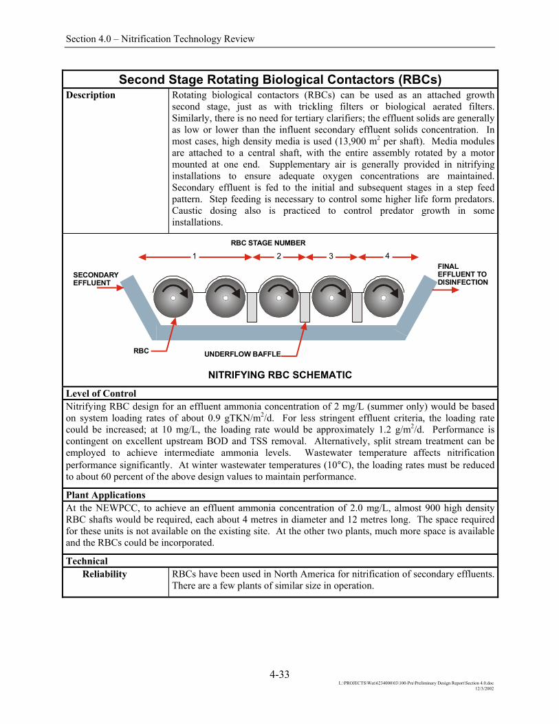
Second Stage Rotating Biological Contactors (RBCs) Description Rotating biological contactors (RBCs) can be used as an attached growth
second stage, just as with trickling filters or biological aerated filters. Similarly, there is no need for tertiary clarifiers; the effluent solids are generally as low or lower than the influent secondary effluent solids concentration. In most cases, high density media is used (13,900 m2 per shaft). Media modules are attached to a central shaft, with the entire assembly rotated by a motor mounted at one end. Supplementary air is generally provided in nitrifying installations to ensure adequate oxygen concentrations are maintained. Secondary effluent is fed to the initial and subsequent stages in a step feed pattern. Step feeding is necessary to control some higher life form predators. Caustic dosing also is practiced to control predator growth in some installations.
1 2 3 4
RBC UNDERFLOW BAFFLE
SECONDARYEFFLUENT
RBC STAGE NUMBER
FINALEFFLUENT TO DISINFECTION
NITRIFYING RBC SCHEMATIC
Level of Control Nitrifying RBC design for an effluent ammonia concentration of 2 mg/L (summer only) would be based on system loading rates of about 0.9 gTKN/m2/d. For less stringent effluent criteria, the loading rate could be increased; at 10 mg/L, the loading rate would be approximately 1.2 g/m2/d. Performance is contingent on excellent upstream BOD and TSS removal. Alternatively, split stream treatment can be employed to achieve intermediate ammonia levels. Wastewater temperature affects nitrification performance significantly. At winter wastewater temperatures (10°C), the loading rates must be reduced to about 60 percent of the above design values to maintain performance.
Plant Applications At the NEWPCC, to achieve an effluent ammonia concentration of 2.0 mg/L, almost 900 high density RBC shafts would be required, each about 4 metres in diameter and 12 metres long. The space required for these units is not available on the existing site. At the other two plants, much more space is available and the RBCs could be incorporated.
Technical Reliability RBCs have been used in North America for nitrification of secondary effluents.
There are a few plants of similar size in operation.
4-33 L:\PROJECTS\Wat\6234000\03\100-Pre\Preliminary Design Report\Section 4.0.doc
12/3/2002

Section 4.0 – Nitrification Technology Review
Second Stage Rotating Biological Contactors (RBCs) (Cont’d.)
Technical (cont’d.) Robustness The attached growth nature of the process makes the system capable of
handling normal fluctuations in hydraulic and nitrogen loading, generally in the range of ± 50 percent of the average design load. Startup requires relatively long acclimation periods, generally needing up to a month to achieve optimal performance.
Flexibility Multiple feed points are preferred to suppress some predator growth on the media. Manipulation of the feed between these inlets provides some flexibility. However, there is limited overall flexibility in this process.
Impact on Other Parts of the Plant
RBCs would be a standalone process. Waste from occasional caustic dosing would impose a small hydraulic load on the remainder of the plant; however, the associated alkalinity addition would likely benefit operations.
Space Requirements
RBCs require substantial space. At the NEWPCC, the space allotment would be approximately 8.0 hectares; at the SEWPCC, 3.5 hectares; and at the WEWPCC, 2.5 hectares.
Expandability This process can be expanded as required to suit additional flows by adding RBCs. RBCs have been used to achieve denitrification; however, a supplemental carbon source would be required. RBCs are incompatible with biological phosphorus removal.
Constructability The construction of a RBC facility would mostly be off-line and would not cause any disruption of normal plant operations. Structural requirements are relatively simple. The existing electrical services would likely require a major revamp to provide sufficient capacity for RBC drives and supplemental aeration blowers.
Operational Ease of Operation RBCs are relatively easy to operate. Step feeding and caustic dosing to control
predators are the major operational tasks and these are not very difficult.
Ease of Maintenance
The number of RBCs required would mandate a substantial maintenance program for the mechanical drives associated with each unit. RBCs are covered, so access is limited to interior components.
Operator Safety RBCs offer few hazards to operations staff.
Operator Environment
The working environment, other than within the RBC enclosure, is relatively innocuous.
Environmental and Aesthetic Traffic There is no difference in traffic associated with this option.
Noise Operating equipment is enclosed and similar to other devices found in wastewater treatment plants. There would be no substantial impact.
Visual RBCs are low profile and would not present much visual nuisance. Fibreglass covers over each unit could be provided in colours which blend with the surroundings and the remaining portions of the plants.
4-34 L:\PROJECTS\Wat\6234000\03\100-Pre\Preliminary Design Report\Section 4.0.doc
12/3/2002
Section 4.0 – Nitrification Technology Review
Second Stage Rotating Biological Contactors (RBCs) (Cont’d.)
Environmental and Aesthetic Odours When used for nitrification, minimal odours from the RBCs are anticipated. In
fact, routing foul air through the RBC enclosures may be an effective way to reduce low level odours in some air streams.
4-35 L:\PROJECTS\Wat\6234000\03\100-Pre\Preliminary Design Report\Section 4.0.doc
12/3/2002

Section 4.0 – Nitrification Technology Review
Second Stage Biological Nitrifying Fluidized Beds Description Fluidized bed treatment relies on generating a fluidized bed of support media
in an upward flow of wastewater. The media usually is graded sand with an effective diameter of about 1.0 mm, on which the nitrifying bacteria grow. Oxygen needed for the oxidation of the ammonia has to be introduced at the bottom of the reactor. To minimize space requirements, it is necessary to achieve very high oxygen levels which can be achieved by using oxygen and high pressures. A proven method is a deep shaft system that can enable a dissolved oxygen concentration of 60 g/L. This design limits the maximum ammonia concentration at the bottom of the reactor to 13 mg/L. A sand cleaning/biomass separation device removes excess biomass and maintains the sand in the reactor. No secondary clarification is needed, assuming the influent is of good quality.
FLUIDIZED BED OF MEDIA
EFFLUENT
OXYGENATEDINFLUENT
WASTEBIOMASS
BIOLOGICAL NITRIFYING FLUIDIZED BED SCHEMATIC
Level of Control Typical loading rates for this quality of effluent are 1 kgN/m3/d; however, treatment is limited by the amount of ammonia that can be removed with the available oxygen. It would be impossible to achieve an effluent ammonia concentration of 2.0 mg/L without high recycles or with excessively deep units. At the NEWPCC, treatment would be limited to about 10 mg/L. At other plants, it is possible that effluent ammonia concentrations as low as 5 mg/L could be reliably achieved. Less stringent levels could be accommodated by decreasing recycle rates.
Plant Applications Biological Nitrifying Fluidized Beds are relatively compact, so would fit within the space constraints of any plant. No other site specific constraints would apply to this option. The centrate load at the NEWPCC would have to be equalized or separately treated to ensure that the contribution of the ammonia from dewatering return flows did not cause erratic performance.
Technical Reliability Fluidized Bed treatment systems are not widely used for municipal wastewater
treatment. A small number of systems are used for industrial treatment including nitrification.
4-36 L:\PROJECTS\Wat\6234000\03\100-Pre\Preliminary Design Report\Section 4.0.doc
12/3/2002
Section 4.0 – Nitrification Technology Review
Second Stage Biological Nitrifying Fluidized Bed (Cont’d.)
Technical (cont’d.) Robustness The attached growth nature of the process makes the system capable of
handling relatively high variations in flow and load, generally in the range of ±50 percent of the average design load. The influent must contain a low concentration of suspended solids or the solids wastage system can become overloaded.
Flexibility Fluidized beds are reasonably flexible but the maximum concentration of ammonia is limited by the maximum dissolved oxygen concentration that can be achieved and the maximum recycle flow that can be pumped to the bottom of the reactor.
Impact on Other Parts of the Plant
Nitrifying fluidized beds would be a stand alone process. Oxygen from the existing plants would have to be routed to the new area and some pumping would need to be accommodated to fluidize the bed. Return solids loads would be minimal.
Space Requirements
Very little space is required for the fluidized beds and the shaft to dissolve the oxygen.
Expandability This process can be expanded as required to suit additional flows by adding fluidized beds. However, fluidized beds are incompatible with biological nitrogen removal and/or phosphorus removal.
Constructability The construction of a fluidized bed facility would mostly be off-line and would not cause any disruption of normal plant operations. The deep shaft for oxygen injection could be problematic at the Winnipeg plants. The existing electrical services would likely require a major revamp to provide sufficient capacity for fluidized bed pumping.
Operational Ease of Operation Fluidized beds are relatively easy to operate. The dissolved oxygen control
system is important to ensure good nitrification. If the variations in load are marked then a simple feedback loop may not be sufficient due to the time lag between oxygen addition and detection at a control point.
Ease of Maintenance
There are a few additional items to maintain; the pumps are the most critical. The dissolved oxygen control and the sand cleaning/solids wastage system must also be closely monitored and maintained as necessary.
Operator Safety The key safety issue is linked to the storage or generation of oxygen. The usual safety rules for oxygen must be observed.
Operator Environment
The working environment is relatively innocuous.
Environmental and Aesthetic Traffic There is no difference in traffic associated with this option.
Noise Operating equipment is enclosed and similar to other devices found in wastewater treatment plants. There would be no substantial impact.
4-37 L:\PROJECTS\Wat\6234000\03\100-Pre\Preliminary Design Report\Section 4.0.doc
12/3/2002

Section 4.0 – Nitrification Technology Review
Second Stage Biological Nitrifying Fluidized Bed (Cont’d.)
Environmental and Aesthetic (cont’d.) Visual Biological fluidized beds would be housed in a new building or an addition to
the existing building. Architectural finishes would be compatible and thus, would cause minimal impacts.
Odours When used for nitrification, minimal odours from this process area are anticipated.
4-38 L:\PROJECTS\Wat\6234000\03\100-Pre\Preliminary Design Report\Section 4.0.doc
12/3/2002

Section 4.0 – Nitrification Technology Review
High Purity Oxygen Two Stage Nitrification Description Two stage high purity oxygen activated sludge (HPOAS) is the most common
configuration for pure oxygen plants which require nitrification. In the two stage configuration, carbonaceous treatment is achieved in the first stage HPO basins and nitrification is achieved in the second stage HPO basins. Clarifiers follow each stage. With this configuration, the pH depression which occurs from CO2 buildup from carbonaceous treatment does not impact the nitrification process as the intermediate clarifier serves as a CO2 stripper. Provided sufficient alkalinity is present in the waste stream to compensate for the alkalinity consumed through nitrification, pH should not be an issue in the nitrification stage.
HPO TWO STAGE NITRIFICATION SCHEMATIC
Level of Control Ammonia With nitrification, wastewater temperature is critical, assuming that pH is
maintained above 6.5. To achieve year round effluent ammonia concentrations of 2 or 5 mg/l will require longer SRTs and thus larger basins. If the ammonia limit of 2 or 5 mg/L is seasonal and only applied to the summer and fall, nitrification can be established following spring runoff. For ammonia concentrations of 10 or 15 mg/L, split treatment using only some of the aeration basins would be used. Effluent from the nitrification trains would be blended with the effluent from the carbonaceous treatment trains to meet permit.
Plant Application North End The existing HPO activated sludge basins would be expanded by adding
downstream nitrification basins. This would involve new HPO basins and new clarifiers. Since this plant processes sludge from all three WWTPs the potential for high ammonia in the centrate from dewatered digested sludge is great and needs consideration in the design of the liquid treatment process both with respect to aeration and alkalinity requirements. The use of second stage nitrification basins may allow an increase in existing final clarifier operating capacity since permit compliance will be a function of the second stage clarifiers.
4-39 L:\PROJECTS\Wat\6234000\03\100-Pre\Preliminary Design Report\Section 4.0.doc
12/3/2002
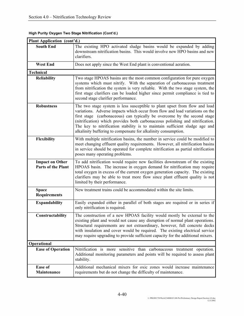
Section 4.0 – Nitrification Technology Review
High Purity Oxygen Two Stage Nitrification (Cont’d.)
Plant Application (cont’d.) South End The existing HPO activated sludge basins would be expanded by adding
downstream nitrification basins. This would involve new HPO basins and new clarifiers.
West End Does not apply since the West End plant is conventional aeration.
Technical Reliability Two stage HPOAS basins are the most common configuration for pure oxygen
systems which must nitrify. With the separation of carbonaceous treatment from nitrification the system is very reliable. With the two stage system, the first stage clarifiers can be loaded higher since permit compliance is tied to second stage clarifier performance.
Robustness The two stage system is less susceptible to plant upset from flow and load variations. Adverse impacts which occur from flow and load variations on the first stage (carbonaceous) can typically be overcome by the second stage (nitrification) which provides both carbonaceous polishing and nitrification. The key to nitrification stability is to maintain sufficient sludge age and alkalinity buffering to compensate for alkalinity consumption.
Flexibility With multiple nitrification basins, the number in service could be modified to meet changing effluent quality requirements. However, all nitrification basins in service should be operated for complete nitrification as partial nitrification poses many operating problems.
Impact on Other Parts of the Plant
To add nitrification would require new facilities downstream of the existing HPOAS basin. The increase in oxygen demand for nitrification may require total oxygen in excess of the current oxygen generation capacity. The existing clarifiers may be able to treat more flow since plant effluent quality is not limited by their performance.
Space Requirements
New treatment trains could be accommodated within the site limits.
Expandability Easily expanded either in parallel of both stages are required or in series if only nitrification is required.
Constructability The construction of a new HPOAS facility would mostly be external to the existing plant and would not cause any disruption of normal plant operations. Structural requirements are not extraordinary, however, full concrete decks with insulation and cover would be required. The existing electrical service may require upgrading to provide sufficient capacity for the additional mixers.
Operational Ease of Operation Nitrification is more sensitive than carbonaceous treatment operation.
Additional monitoring parameters and points will be required to assess plant stability.
Ease of Maintenance
Additional mechanical mixers for oxic zones would increase maintenance requirements but do not change the difficulty of maintenance.
4-40 L:\PROJECTS\Wat\6234000\03\100-Pre\Preliminary Design Report\Section 4.0.doc
12/3/2002

Section 4.0 – Nitrification Technology Review
High Purity Oxygen Two Stage Nitrification (Cont’d.)
Operational (cont’d.) Operator Safety No new safety concerns would arise since the processes are biological. If
chemical addition is required for alkalinity supplementation this could result in some additional safety issues depending on the chemical used.
Operator Environment
No change from existing operations.
Environmental and Aesthetic Traffic There is no difference in traffic associated with this option.
Noise Operating equipment is similar to existing equipment in wastewater treatment plants. There would be no substantial impact.
Visual Aeration basins are underground and covered similar to existing tanks. Architectural finishes would be compatible and thus, would cause minimal impacts.
Odours With covered basins no odours are anticipated. Odours have not traditionally been a problem with anaerobic and anoxic zones at other plants.
4-41 L:\PROJECTS\Wat\6234000\03\100-Pre\Preliminary Design Report\Section 4.0.doc
12/3/2002

Section 4.0 – Nitrification Technology Review
Mainstream Treatment Train – Ammonia Stripping Description As applied to the mainstream treatment train, ammonia stripping would be an
add-on process in which the pH of the wastewater would be raised to ~10.6 to ~11.5 in order to convert NH4
+ to NH3(g). The high pH wastewater would be passed through a trickle-flow packed tower with counter-current air flow. A second pH adjustment using acid addition is necessary prior to discharge to a receiving waterbody.
Tower media are typically horizontal packed members made of wooden slats or ~12 mm pipe lengths spaced about 5 cm apart both horizontally and vertically. The hydraulic loading on the media is kept relatively low in order to avoid sheet flow and to ensure multiple points of repeated droplet formation and rupture throughout the height of the tower thereby increasing the liquid film mass transfer coefficient which is an important limiting factor.
Conceivably NH3 could be recovered from the off gas stream by employing a closed loop stripper/absorber configuration; however, this has not been proven economically effective on mainstream treatment applications. Furthermore an environmental analysis of the tower exhaust (Culp et al, 1978) indicates that unless the tower is located immediately upwind in close proximity of a lake or reservoir, the return of ammonia to the aquatic environment will not be significant.
Two plant-scale installations of ammonia stripping were installed in the 1970’s – one at Lake Tahoe and the other in Orange County, California. Both have since been removed from service due to freezing problems with the former and scaling problems with both the former and the latter.
AIR OUTLET
WATER INLETWATER INLET
FILL
DRIFTELIMINATORS
WATEROUTLET
COLLECTIONBASIN
CROSS-FLOW TOWER
FAN
AIRINLET
AIRINLET
AIR OUTLET
WATER INLET
DRIFTELIMINATORS
DISTRIBUTION SYSTEM
WATERCOLLECTIONBASIN
CONCURRENT TOWER
FAN
AIRINLET
AIR INLET
FILL
TYPES OF STRIPPING TOWERS
[From Culp, Wesner & Clup, Handbook of Advanced Wastewater Treatment, 2nd Edition, Van Nostrand Reinhold Company, New York 1978]
4-42 L:\PROJECTS\Wat\6234000\03\100-Pre\Preliminary Design Report\Section 4.0.doc
12/3/2002

Section 4.0 – Nitrification Technology Review
Mainstream Treatment Train – Ammonia Stripping (Cont’d.)
Level of Control Air stripping towers are capable of achieving 90 to 95 % removal of ammonia from wastewater during warm weather operation. Under these conditions for a typical domestic wastewater, treated effluent NH3-N concentrations in the range of 2 to 4 mg/L can be realized. In colder weather, the wastewater temperature is usually lower and the solubility of ammonia is greater, thereby reducing the removal efficiency of the process to ~50 % or less. Steam stripping could be used to offset this phenomenon; however, the cost of providing steam to heat the entire mainstream treatment flow would be prohibitive.
Liquid flowing through the tower will tend to freeze due to evaporative cooling as the ambient air temperature approaches 0°C. Therefore it is not feasible to operate the system during cold weather. A closed loop system incorporating a stripping tower and an absorption tower could be used; however, as noted previously this would not be realistic for a mainstream treatment train.
Plant Applications This technology is specific for ammonia gas or the ammonium ion that is transformed to ammonia gas in solution at higher pH levels. Thus wastewater containing significant amounts of organic nitrogen must be given a sufficient amount of bacterial treatment to convert the organic nitrogen to ammonium but not to nitrite or to nitrate.
The facilities to be provided at each plant would include a pH adjustment system complete with bulk lime or caustic and acid storage and metering systems, an effluent pumping station to lift the wastewater to the top of the stripping tower, and the stripping tower system itself complete with structure, packing, air and liquid distribution baffles, and induced draft fans.
Technical Reliability While the concept is relatively simple and has been demonstrated to work, full-
scale applications have suffered from serious scaling problems which ultimately caused the technology to be abandoned in favour of other approaches. Attempts to address the scaling problem by using media with smooth surfaces have been only partially successful. In addition as noted previously, stripping towers cannot be operated during cold weather conditions.
Robustness Increases in ammonia loading rates can be handled to some extent by increasing the fan speed, and hence the flow of counter-current air, in the tower.
Flexibility The process is relatively simple and straightforward and little flexibility is provided, other than to increase the fan speed and air flowrate.
Impact on Other Parts of the Plant
There would be little impact on other parts of the plant.
Space Requirements
Assuming hydraulic loading on the tower packing of 1 L/s/m2 and a packing height of at least 10 m, the minimum area requirements at the NE, SE and WE plants would be approximately 2.0 ha, 0.4 ha and 0.3 ha respectively.
Expandability Additional stripping towers could be constructed to deal with increasing flows. Additional media and hence tower height could be added to cope with increasing ammonia concentrations. This likely would be problematic.
4-43 L:\PROJECTS\Wat\6234000\03\100-Pre\Preliminary Design Report\Section 4.0.doc
12/3/2002

Section 4.0 – Nitrification Technology Review
Mainstream Treatment Train – Ammonia Stripping (Cont’d.)
Technical (cont’d.) Constructability Because this is an add-on process, no special constructability issues are likely
to arise. The most critical construction item would be the final tie-in of the new effluent pumping station to the existing secondary effluent line.
Operational Ease of Operation The process would be relatively straightforward to operate and require few
skills in addition to those already available with the plant operating staff.
Ease of Maintenance
Excessive scaling problems reported in the early prototype installations eventually led to the abandonment of this technology. High pressure hoses were used to remove scale with varying degrees of success.
Operator Safety There is a need for elevated access to service the fan mechanisms. The provision of appropriate platforms, safety railings and safety harnesses should minimize any risk of injury.
Operator Environment
No particular adverse operating environment is envisioned provided that the unit is shut down for servicing of the fan.
Environmental and Aesthetic Traffic Bulk lime and acid delivery trucks would be the only additional traffic
anticipated for the facility.
Noise Fan noise and water dripping noises could be issues for nearby residence. To some extent, measures can be taken to control these noise emissions.
Visual The stripping towers would be highly visible on the site of each plant. The towers themselves would be a minimum of 15 m high including packing, flow distribution systems, fan mechanism and exhaust duct. In addition, there would be an obvious fog/mist plume emanating from each exhaust duct.
Odours Little or no odour emissions would be anticipated.
4-44 L:\PROJECTS\Wat\6234000\03\100-Pre\Preliminary Design Report\Section 4.0.doc
12/3/2002

Section 4.0 – Nitrification Technology Review
Mainstream Treatment Train – Selective Ion Exchange Description Filtered effluent is directed to a downflow packed bed ion adsorption column
containing 50 x 80 mesh of a naturally occurring zeolyte media called clinoptilolite. This media exhibits the following major ion selectivity:
K+ > NH3+ > Na+ > Ca++ > Mg++
Once the exchange capacity of the media is exhausted, the bed is backwashed to remove solids and then is regenerated with a concentrated brine solution. Ammonia can be recovered from the spent regenerant in the form of ammonia gas, ammonium sulphate or ammonium nitrate using a closed loop stripper/absorber system, depending on the recovery technology employed.
A handful of full-scale ammonia removal selective ion exchange plants have been constructed in North America, one of the largest being at the Upper Occoquan WWTP in Virginia which was commissioned in the early 1980’s but is no longer in service.
CLINOPTILOLITE BED
SPENT REGENERANT
FRESH REGENERANT
EFFLUENT
INFLUENT
AMMONIA OR NITROGEN
GAS OR RECOVERED
REGENERANTRECOVERY
SCHEMATIC OF SELECTIVE ION EXCHANGE PROCESS [From Culp, Wesner & Clup, Handbook of Advanced Wastewater Treatment, 2nd Edition, Van
Nostrand Reinhold, Company, 1978] Level of Control Treated effluent NH3-N concentrations in the range of 2 to 5 mg/L are achievable with single stage ion exchange columns. Lower concentrations are attainable by placing two or more columns in series with the last column in series being the one most recently regenerated. The complex piping and valving arrangements required for interchangeability adds significantly to the complexity and cost of series systems.
4-45 L:\PROJECTS\Wat\6234000\03\100-Pre\Preliminary Design Report\Section 4.0.doc
12/3/2002

Section 4.0 – Nitrification Technology Review
Mainstream Treatment Train – Selective Ion Exchange (Cont’d.)
Plant Applications This technology is specific for the ammonium ion and therefore must be operated in the pH range from ~4 to ~8 to prevent formation of ammonia gas in solution. Thus wastewater containing significant amounts of organic nitrogen must be given a sufficient amount of bacterial treatment to convert the organic nitrogen to ammonium but not to nitrite or to nitrate.
The facilities to be provided at each plant would include a pre-filtration system, the ion exchange beds, regenerant storage and pumping system, spent regenerant renewal and ammonia recovery system, and all related ancillaries. In addition, an effluent pumping station would be required to supply the wastewater to the ion exchange system.
Technical Reliability Ion exchange technology is quite well developed and has been used
successfully in the production of high quality boiler feedwater and also in the electronics industry for several years. Backup equipment would be provided for all critical systems.
Robustness Varying ammonia loads would best be handled by placing ion exchange columns in series, albeit at an increase in the complexity of the overall system.
Flexibility The pumping, piping, valving and control systems typically associated with ion exchange systems usually will provide sufficient operational flexibility to cope with a variety of conditions.
Impact on Other Parts of the Plant
Spent filter backwash water and sludge residuals from the regenerant solution renewal system would be directed to the primary treatment system of the plant for processing. These are expected to have little impact on the overall wastewater treatment process.
Space Requirements
Assuming hydraulic loading rate of 3 L/sec/m2 and 8 bed volumes per hour, the minimum area requirements at the NE, SE and WE plants would be approximately 3.0 ha, 0.75 ha and 0.5 ha respectively for the pre-filtration system, the ion exchange beds, the regenerant system, and the spent regenerant renewal and ammonia recovery systems.
Expandability Additional ion exchange systems could be added as necessary to cope with increased loads.
Constructability Because this is an add-on process, no special constructability issues are likely to arise. The most critical construction item would be the final tie-in of the new effluent pumping station to the existing secondary effluent line.
Operational Ease of Operation The system would be very complex; however, much of the equipment operation
could be automated.
Ease of Maintenance
Ion exchange would be a very complex and maintenance-intensive system. The equipment and materials of construction would be expensive.
Operator Safety Ion exchange will involve the handling of corrosive liquids and thus poses operator safety issues in addition to those commonly found around an activated sludge plant.
4-46 L:\PROJECTS\Wat\6234000\03\100-Pre\Preliminary Design Report\Section 4.0.doc
12/3/2002

Section 4.0 – Nitrification Technology Review
Mainstream Treatment Train – Selective Ion Exchange (Cont’d.)
Operational (cont’d.) Operator Environment
The operating environment of the ion exchange system would be typical of a very large boiler feedwater treatment system common to a high pressure steam power generation plant.
Environmental and Aesthetic Traffic Additional truck traffic associated with the delivery of the brine and acid make-
up solutions as well as the shipping of the recovered ammonia product would occur.
Noise All operating equipment would be enclosed in a building and thus noise emissions would be minimal.
Visual The ion exchange facility would be housed in a building that would be typical in construction to other buildings on the treatment plant site.
Odours There would be minimal odour emissions from the ion exchange facility.
4-47 L:\PROJECTS\Wat\6234000\03\100-Pre\Preliminary Design Report\Section 4.0.doc
12/3/2002

Section 4.0 – Nitrification Technology Review
Mainstream Treatment Train – Breakpoint Chlorine Description This process has been adopted from the water treatment industry. Chlorine,
when initially added to water containing ammonia, results in the formation of chloramines (NH2Cl and NHCl2) which produces a combined chlorine residual. The addition of more chlorine reacts with the chloramines resulting in nitrogen gas as a principal product and a reduction in the combined chlorine residual. Eventually a “breakpoint” is reached at which the continuing addition of chlorine results in a free chlorine residual (Cl2(g), HOCl or OCl-).
A theoretical molar ratio of [7.6 : 1] [Cl2 : NH4+-N] is required to reach the
“breakpoint” of the reaction. In wastewater treatment applications, there are numerous competing reactions and the required molar ratio is usually at least [10 : 1]. A considerable amount of alkalinity is consumed by the breakpoint reactions. The stoichiometric alkalinity loss is 14.3 mg/L of bicarbonate alkalinity (as CaCO3) per mg/L of NH4
+-N destroyed. In order to minimize the risk of chlorine toxicity, dechlorination with SO2 is required to remove the free chlorine residual prior to discharge to a receiving waterbody.
Reactions: Cl2 + H2O ⇒ HOCl + H+ + Cl-
NH4+ + HOCl ⇒ NH2Cl + H2O + 2H+
2NH2Cl + HOCl ⇒ N2 + H2O + 3H+ + 3Cl-
Overall: 1.5Cl2 + NH4
+ ⇒ 0.5N2 + 4H+ + 3Cl-
MOLE RATIO, Cl2:NH4-N
0
2
4
6
8
10
0 2 4 6 8 10
CHLORINE DOSAGE (mg/L)
RES
IDU
AL
CH
LOR
INE
(mg/
L)
0.5
12
1.0 1.5 2.0
CHLORINE APPLIED CURVE
BREAKPOINT
FREE CHLORINE RESIDUAL PREDOMINANTCOMBINED CHLORINE RESIDUALS PREDOMINANT
TYPICAL BREAKPOINT CHLORINATION CURVE
[From Culp, Wesner & Clup, Handbook of Advanced Wastewater Treatment, 2nd Edition, Van Nostrand Reinhold Company, New York 1978]
4-48 L:\PROJECTS\Wat\6234000\03\100-Pre\Preliminary Design Report\Section 4.0.doc
12/3/2002

Section 4.0 – Nitrification Technology Review
Mainstream Treatment Train – Breakpoint Chlorine (Cont’d.)
Level of Control The process is capable of achieving quite low NH3-N concentrations to less than 2 mg/L.
Because of the relatively large quantity of chlorine required to reach the breakpoint, the process is seldom used as a principal means of ammonia control; rather it has been applied more as a polishing step for ammonia removal following another type of treatment process.
Plant Applications This technology is specific for the ammonium ion and therefore must be operated at a pH of less than ~8 to prevent formation of ammonia gas in solution. Thus wastewater containing significant amounts of organic nitrogen must be given a sufficient amount of bacterial treatment to convert organic nitrogen to ammonium but not to nitrite or nitrate.
As a principal ammonia removal technology, chlorination will require large quantities of chemical to achieve the breakpoint. At the NEWPCC, this would amount to between one and two rail cars of liquid chlorine each day while at the SE and WE plants, about 15 and 10 one tonne chlorine cylinders would be required each day. If breakpoint chlorination were used as a polishing step, these amounts would be reduced by a factor of five to ten.
Facilities to be provided at each plant would include bulk chlorine and sulphur dioxide receiving, storage, evaporating and metering and control system, a containment and scrubbing system, a rapid mix injection and dispersion chamber for chlorine injection, a one minute plug flow contact tank to allow the breakpoint reactions to occur, and a second rapid mix and dispersion chamber for dechlorination with sulphur dioxide. These could be installed within the constraints of the hydraulic profiles of each plant with no need for effluent pumping.
Technical Reliability Chlorination and dechlorination technology is well developed and has been
widely applied for many decades. It is likely that for the amount of chlorine to be applied in this application, alkalinity will be required to maintain the pH of the effluent in a neutral range not only to comply with effluent discharge limits but also to minimize the risk of forming the toxic NCl3 byproduct of the breakpoint reactions.
Robustness Varying ammonia loads can be handled by adjusting the chlorine dosage accordingly. This would be done with an automatic control system including flow measurement and ammonia and chlorine sensing devices.
Flexibility Sufficient flexibility can be readily provided to deal with removal of equipment for maintenance.
Impact on Other Parts of the Plant
There would be little impact on other parts of the plant.
Space Requirements
Space requirements for breakpoint chlorination would be relatively modest. The most space would be required for the bulk chlorine and sulphur dioxide receiving, storage, evaporating and metering systems together with their related containment and scrubbing systems.
Expandability The process would be readily expandable by the addition of more chlorination equipment.
4-49 L:\PROJECTS\Wat\6234000\03\100-Pre\Preliminary Design Report\Section 4.0.doc
12/3/2002

Section 4.0 – Nitrification Technology Review
Mainstream Treatment Train – Breakpoint Chlorine (Cont’d.)
Technical (cont’d.) Constructability No particular impediments to construction are anticipated. Appropriate tie-ins
to the existing effluent channels would be required when it is time to commission the rapid mixing and contact tank.
Operational Ease of Operation Normal operation would be entirely automated and would generally require
only periodic attention and monitoring by the operating staff. The most labour intensive operational requirements would be for changing from empty to full chlorine (or sulphur dioxide) rail cars and containers.
Ease of Maintenance
Maintenance would be relatively straightforward and typical of equipment maintenance requirements commonly found in many water/wastewater treatment facilities.
Operator Safety Because of the extremely hazardous nature of chlorine and sulphur dioxide, special training must be given to the plant operating and maintenance staff to minimize the risk of an incident and to deal properly with an incident should one occur.
Operator Environment
The operator’s environment would be little different to that at a typical water/wastewater treatment facility.
Environmental and Aesthetic Traffic There would be additional traffic for the delivery and removal of full and empty
rail cars and cylinders containing chlorine and sulphur dioxide. In addition periodic deliveries of bulk caustic solution would be required.
Noise There would be little noise emitted from the facility.
Visual The new building housing the chlorination, containment and scrubbing facilities would be apparent on each plant site. In addition, a new rail car siding(s) would be required at the NEWPCC.
Odours Some chlorine odour may be noticeable in the immediate vicinity of the chlorine dosing point; however, the odour would dissipate rapidly as one moves away from this point.
4-50 L:\PROJECTS\Wat\6234000\03\100-Pre\Preliminary Design Report\Section 4.0.doc
12/3/2002

Section 4.0 – Nitrification Technology Review
Centrate Treatment – Ammonia Stripping & Recovery Description A closed loop system consisting of a counter-current trickle-flow packed
stripping tower followed by either a counter-current or co-current absorption tower would be used to strip and recover the ammonia from the centrate. (See sketches below.) An advantage of this system is that the nitrogen in the ammonia is removed from the treatment process entirely thus resulting in a certain degree of total nitrogen removal from the system.
Alkali would be added to the centrate feedstock to raise the pH and convert the ammonium ion to ammonia so that it can be more easily removed in the stripping column. There would be a relatively low loading on the stripping column to promote multiple points of repeated droplet formation and rupture throughout the column height and to avoid sheet flow. Steam could be used in the stripping column as necessary to increase the removal of ammonia.
Sulphuric acid (or hydrochloric or nitric acid) would be used in the absorption column to recover the ammonia as an ammonium salt solution. Due to the more favourable equilibrium associated with the absorption step, the absorption column would be about one-third of the size of the stripping column. The ammonium sulphate product may have a fertilizer value; alternately, it could be steam stripped to recover ammonia.
CENTRATE FEED
ALKALI SOLUTION
STRIPPED CENTRATE PRODUCT
H S0SOLUTION
2 4
AMMONIUM SULPHATE SOLUTION
BLOWDOWN
PACKING
DEMISTER
DEMISTER
FAN
SCHEMATIC OF SIDE-BY-SIDE COUNTER-CURRENT STRIPPING COLUMN AND CO-
CURRENT ABSORPTION COLUMN
4-51 L:\PROJECTS\Wat\6234000\03\100-Pre\Preliminary Design Report\Section 4.0.doc
12/3/2002

Section 4.0 – Nitrification Technology Review
Centrate Treatment – Ammonia Stripping & Recover (Cont’d.)
ALKALI SOLUTION
CENTRATE FEED
STRIPPED CENTRATE PRODUCT
H S0SOLUTION
2 4
AMMONIUM SULPHATE SOLUTION
BLOWDOWN
DEMISTER
PACKING
DEMISTER
PACKING
FAN
SCHEMATIC OF STACKED STRIPPER AND ABSORBER PACKED TOWERS
Level of Control Ammonia removal in the stripper column will be a function primarily of temperature, pH and the airflow to waterflow ratio. The warm temperature of the centrate stream will favour good ammonia removal because of a lower solubility than at typical effluent temperatures. The high pH and a high air to water ratio will also favour good ammonia removal. Under suitable design and operating conditions, ammonia removals in excess of 95% can be achieved in the tower. If the mainstream processing train is not designed to nitrify, then the total nitrogen removal from the integrated system will be in the order of 50% (~30% due to nitrogen removal by cellular synthesis in the mainstream bioreactor and ~20% from the ammonia stripping of the centrate).
Wastewater Treatment Plant Specific Considerations At the North End plant, three stripper/absorber systems would be installed, each one capable of processing one-half of the centrate flow. In this manner, full processing capacity would be available if one of the three units were out of service. One of the old digesters would be converted to a mixed centrate receiving tank, thereby serving as surge storage to equalize flow and load fluctuations of the centrate. Other facilities would include a centrate pumping station as well as alkali and acid storage and metering systems, and a receiving/holding tank for the ammonium sulphate solution product.
4-52 L:\PROJECTS\Wat\6234000\03\100-Pre\Preliminary Design Report\Section 4.0.doc
12/3/2002

Section 4.0 – Nitrification Technology Review
Centrate Treatment – Ammonia Stripping & Recover (Cont’d.)
Technical Reliability Because of the closed loop configuration of the system, the scaling and freezing
problems that have plagued mainstream ammonia stripping systems should not occur for this sidestream system. The stripping/absorption technology is relatively simple and has been applied in numerous applications in the chemical processing industries.
Robustness The process can withstand moderate fluctuations in ammonia loadings with adjustments to the alkali dosage and/or the counter-current gas flow rate.
Flexibility The process is relatively simple and straightforward to operate. A limited amount of flexibility is available for the operator in that the chemical dosages and the airflow rate can be adjusted.
Impact on Other Parts of the Plant
The main impact on other parts of the plant will be the elimination of the nitrogen load on the secondary treatment system originating from the centrate stream. This amounts to about 20 to 25 % of the secondary influent nitrogen loading.
Space Requirements
Approximately 0.2 ha would be required at the NEWPCC for the effluent pumping station, the three stripper/absorber units, the bulk alkali, acid and product storage tanks, and the related access roads.
Expandability The system would be easily expandable by adding a fourth stripper/absorber unit and ancillary equipment as necessary.
Constructability Construction can occur without hampering the ongoing operation of the plant. A brief minor interruption will occur when the tie-in of the new centrate pumping station is made.
Operational Ease of Operation While this would be new technology to the operating staff with which they
likely have no familiarity, it would be a relatively straightforward process to operate. With the appropriate training, the operators could acquire the few additional skills that they would need to operate it effectively.
Ease of Maintenance
Additional maintenance work will be required to service the pumps and fans, although this type of equipment would be familiar to the plant’s maintenance staff. Periodically, the tower packing will require inspection. It may be necessary to add slimicides to the liquid phase in order to minimize biological growths in the packing that could impair the efficiency of the process.
Operator Safety Elevated platforms would be required to access the top of the stripping and absorption columns. Appropriate access stairways and hand railings can be provided to minimize any safety risks. Proper training for the operators will be required for the handling of the bulk alkali and acid chemicals.
Operator Environment
Under normal operation, no particular adverse conditions should occur in the operators’ environment.
Environmental and Aesthetic Traffic There would be periodic bulk tanker truck receipts of acid and alkali, as well as
deliveries of ammonium sulphate solution product.
4-53 L:\PROJECTS\Wat\6234000\03\100-Pre\Preliminary Design Report\Section 4.0.doc
12/3/2002

Section 4.0 – Nitrification Technology Review
Centrate Treatment – Ammonia Stripping & Recover (Cont’d.)
Environmental and Aesthetic (cont’d.) Noise The major source of noise from the system would be the fan noise and this
could be contained.
Visual The stripping/absorption columns would be visible, as would the bulk liquid chemical storage tanks.
Odours The closed-loop design of the system will minimize the risk of odour emissions. There may be some odour associated with the ammonium sulphate product.
4-54 L:\PROJECTS\Wat\6234000\03\100-Pre\Preliminary Design Report\Section 4.0.doc
12/3/2002

Section 4.0 – Nitrification Technology Review
Centrate Treatment – Nitrifying Biox Unit Description A relatively small completely mixed activated sludge system operating
independently of the existing mainstream HPO treatment units would be installed to treat centrate. The system would be designed to nitrify the high ammonia concentration in the centrate stream. The relatively warm (25-30°C) centrate stream will enable nitrifying organisms to grow at a relatively modest HRT (say 10-15 hours) and SRT (say 5-8 days).
The nitrate-rich product stream would be returned to the primary effluent where the nitrate-oxygen could be used as an oxygen source to oxidize soluble biodegradable carbon if an anoxic zone were constructed at the head end of the mainstream bioreactor. The waste activated sludge from the centrate biox unit would be directed to the mainstream bioreactor to enhance the nitrification efficiency of the mainstream treatment process.
It is likely that the addition of alkali will be required to the centrate biox unit to maintain the pH in a range suitable for good nitrification. Also, the bioreactor of the biox unit will require covering and the exhaust gases treated for odour control.
CENTRATE DEWATERING CENTRIFUGES
ANAEROBIC DIGESTERS
RAWSEWAGE
O2O2
O2
PRIMARY TREATMENT
SIDESTREAM CLARIFIER
SIDESTREAM BIOX UNIT
ALKALINITY OFF-GAS SCRUBBER
EXHAUST TO ATMOSPHERE
BIOREACTOR SECONDARY TREATMENT
SECONDARYEFFLUENT
WAS-1
RAS-1
RAS-2
PRIMARYSLUDGE
NITRATE-RICHRETURN STREAM
BIOSLUDGE TOLAND APPLICATION
SCHEMATIC OF CENTRATE BIOLOGICAL TREATMENT SCHEME (Dotted Oval) AND ITS
RELATIONSHIP TO THE OVERALL TREATMENT PROCESS
4-55 L:\PROJECTS\Wat\6234000\03\100-Pre\Preliminary Design Report\Section 4.0.doc
12/3/2002
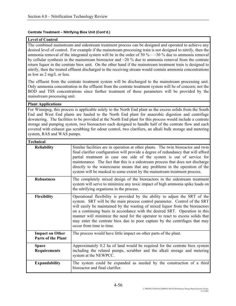
Section 4.0 – Nitrification Technology Review
Centrate Treatment – Nitrifying Biox Unit (Cont’d.)
Level of Control The combined mainstream and sidestream treatment process can be designed and operated to achieve any desired level of control. For example if the mainstream processing train is not designed to nitrify, then the ammonia removal of the integrated system will be in the order of 50 % – ~30 % due to ammonia removal by cellular synthesis in the mainstream bioreactor and ~20 % due to ammonia removal from the centrate return liquor in the centrate biox unit. On the other hand if the mainstream treatment train is designed to nitrify, then the treated effluent discharged to the receiving stream would contain ammonia concentrations as low as 2 mg/L or less.
The effluent from the centrate treatment system will be discharged to the mainstream processing unit. Only ammonia concentration in the effluent from the centrate treatment system will be of concern; not the BOD and TSS concentrations since further treatment of these parameters will be provided by the mainstream processing unit.
Plant Applications For Winnipeg, this process is applicable solely to the North End plant as the excess solids from the South End and West End plants are hauled to the North End plant for anaerobic digestion and centrifuge dewatering. The facilities to be provided at the North End plant for this process would include a centrate storage and pumping system, two bioreactors each designed to handle half of the centrate flow and each covered with exhaust gas scrubbing for odour control, two clarifiers, an alkali bulk storage and metering system, RAS and WAS pumps.
Technical Reliability Similar facilities are in operation at other plants. The twin bioreactor and twin
final clarifier configuration will provide a degree of redundancy that will afford partial treatment in case one side of the system is out of service for maintenance. The fact that this is a sidestream process that does not discharge directly to the watercourse means that any problems in the operation of the system will be masked to some extent by the mainstream treatment process.
Robustness The completely mixed design of the bioreactors in the sidestream treatment system will serve to minimize any toxic impact of high ammonia spike loads on the nitrifying organisms in the process.
Flexibility Operational flexibility is provided by the ability to adjust the SRT of the system. SRT will be the main process control parameter. Control of the SRT will easily be maintained by the wasting of mixed liquor from the bioreactors on a continuing basis in accordance with the desired SRT. Operation in this manner will minimize the need for the operator to react to excess solids that may enter the centrate biox due to poor capture by the centrifuges that may occur from time to time.
Impact on Other Parts of the Plant
The process would have little impact on other parts of the plant.
Space Requirements
Approximately 0.2 ha of land would be required for the centrate biox system including the related pumps, scrubber and the alkali storage and metering system at the NEWPCC.
Expandability The system could be expanded as needed by the construction of a third bioreactor and final clarifier.
4-56 L:\PROJECTS\Wat\6234000\03\100-Pre\Preliminary Design Report\Section 4.0.doc
12/3/2002

Section 4.0 – Nitrification Technology Review
Centrate Treatment – Nitrifying Biox Unit (Cont’d.)
Constructability No particular constructability issues are envisioned.
Operational Ease of Operation The system would be operated much like any other biological treatment system
owned and operated by the City. The only difference would be that the main operating parameter would be the SRT of the system and this would be established by the rate at which mixed liquor would be withdrawn from the bioreactors. For example, if it is desired to operate at an 8 day SRT, then the wasting pump would be set to withdraw 12.5% of the total bioreactor volume each day from the system.
Ease of Maintenance
Maintenance would be similar to that which is done in other parts of the plant.
Operator Safety No unusual operator safety issues are envisioned.
Operator Environment
The operator’s environment would be similar in many respects to that which exists in other parts of the plant.
Environmental and Aesthetic Traffic There would be little impact on traffic.
Noise Noise emissions would not be much different than at present.
Visual The addition of a relatively small clarifier and bioreactor complex, together with the associated building to house the ancillary equipment would be compatible with the existing appearance of the plant. The only unique feature would be the bulk alkali storage tank; however, such a tank would not be an unusual site at a wastewater treatment facility.
Odours As noted above, the bioreactor would be covered and the exhaust gases scrubbed to minimize any odours emanating from the incoming centrate stream.
4-57 L:\PROJECTS\Wat\6234000\03\100-Pre\Preliminary Design Report\Section 4.0.doc
12/3/2002

Section 4.0 – Nitrification Technology Review
Centrate Treatment – MAP (Struvite) Precipitation Description Magnesium Ammonium Phosphate (MAP - MgNH4PO4), a mineral often
referred to as “struvite” with a 1:1:1 molar ratio of Mg:N:P, would be precipitated at a slightly alkaline pH from the centrate stream of the NEWPCC. The intent would be to substantially lower the ammonia level in the centrate return to the mainstream treatment train.
The precipitation would be accomplished in an air-agitated crystallization column with the addition of a magnesium salt and phosphoric acid to achieve the desired molar ratio, and an alkali for pH control. An odour control system would be installed on the off gases from the reaction section of the crystallizer. The crystals in the product stream would be separated from the carrying fluid by means of a static screen and recovered for their nutrient value as an additive for compost, sludge, soil, etc. While relatively high chemical dosages would be required to accomplish the precipitation, an advantage of the process is that a useful product is generated. Another advantage is that the nitrogen load associated with the centrate is removed from the treatment process entirely thus resulting in a certain degree of total nitrogen removal from the system.
The process has been demonstrated on a full-scale basis in Japan and Europe for treatment of sidestream return liquors.
MAP PRODUCT
MAP/LIQUID SEPARATORAIR-ACTIVATED CRYSTALLIZER
PUMP
H PO3 4
MgCl2
NaOHCENTRATE FEED
AIR
RETURN TO MAINSTREAM
TO ATMOSPHERE
ODOUR CONTROL SYSTEM
SKETCH OF MAP CRYSTALLIZATION PROCESS FOR CENTRATE TREATMENT
4-58 L:\PROJECTS\Wat\6234000\03\100-Pre\Preliminary Design Report\Section 4.0.doc
12/3/2002
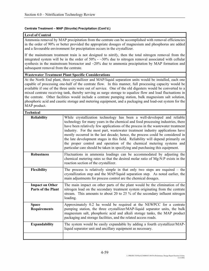
Section 4.0 – Nitrification Technology Review
Centrate Treatment – MAP (Struvite) Precipitation (Cont’d.)
Level of Control Ammonia removal by MAP precipitation from the centrate can be accomplished with removal efficiencies in the order of 90% or better provided the appropriate dosages of magnesium and phosphorus are added and a favourable environment for precipitation occurs in the crystallizer.
If the mainstream treatment train is not designed to nitrify, then the total nitrogen removal from the integrated system will be in the order of 50% - ~30% due to nitrogen removal associated with cellular synthesis in the mainstream bioreactor and ~20% due to ammonia precipitation by MAP formation and subsequent removal from the centrate.
Wastewater Treatment Plant Specific Considerations At the North End plant, three crystallizer and MAP/liquid separation units would be installed, each one capable of processing one-half of the centrate flow. In this manner, full processing capacity would be available if one of the three units were out of service. One of the old digesters would be converted to a mixed centrate receiving tank, thereby serving as surge storage to equalize flow and load fluctuations in the centrate. Other facilities would include a centrate pumping station, bulk magnesium salt solution, phosphoric acid and caustic storage and metering equipment, and a packaging and load-out system for the MAP product.
Technical Reliability While crystallization technology has been a well-developed and reliable
technology for many years in the chemical and food processing industries, there have been relatively few applications of the process in the wastewater treatment industry. For the most part, wastewater treatment industry applications have mostly occurred in the last decade; hence, the process could be considered in the late development stages in this field. Reliability will depend primarily on the proper control and operation of the chemical metering systems and particular care should be taken in specifying and purchasing this equipment.
Robustness Fluctuations in ammonia loadings can be accommodated by adjusting the chemical metering rates so that the desired molar ratio of Mg:N:P exists in the reaction section of the crystallizer.
Flexibility The process is relatively simple in that only two steps are required – the crystallization step and the MAP/liquid separation step. As noted earlier, the main adjustments for process control are the chemical dosages.
Impact on Other Parts of the Plant
The main impact on other parts of the plant would be the elimination of the nitrogen load on the secondary treatment system originating from the centrate stream. This amounts to about 20 to 25 % of the secondary influent nitrogen loading.
Space Requirements
Approximately 0.2 ha would be required at the NEWPCC for a centrate pumping station, the three crystallizer/MAP-liquid separator units, the bulk magnesium salt, phosphoric acid and alkali storage tanks, the MAP product packaging and storage facilities, and the related access roads.
Expandability The system would be easily expandable by adding a fourth crystallizer/MAP-liquid separator unit and ancillary equipment as necessary.
4-59 L:\PROJECTS\Wat\6234000\03\100-Pre\Preliminary Design Report\Section 4.0.doc
12/3/2002

Section 4.0 – Nitrification Technology Review
Centrate Treatment – MAP (Struvite) Precipitation (Cont’d.)
Technical (cont’d.) Constructability Construction can occur without hampering the ongoing operation of the plant.
A brief minor interruption will occur when the tie-in of the new centrate pumping station is made.
Operational Ease of Operation This would be a new technology for the operating staff and they would likely
have no familiarity with it. With the appropriate training, the operators could acquire the additional skills that they would need to operate it effectively. Particular care will be required to monitor and maintain the proper chemical dosage rates.
Ease of Maintenance
Additional maintenance work will be required to service the chemical metering equipment; however this type of work should be familiar to the plant’s maintenance staff.
Operator Safety Proper training will be required for the operators to handle the bulk chemicals required for the process.
Operator Environment
Under normal operation, no particular adverse environmental conditions should occur in the operator’s environment.
Environmental and Aesthetic Traffic There would be periodic bulk tanker truck receipts of magnesium salts,
phosphoric acid and alkali, as well as shipments of the MAP product.
Noise There would be little additional noise associated with the system.
Visual The crystallization and MAP-liquid separation units would be housed inside a new building. The bulk chemical storage tanks would be visible.
Odours Presuming an odour control device would be installed on the off gases from the reaction zone of the crystallizer, there would be little odour emissions from the facility.
4-60 L:\PROJECTS\Wat\6234000\03\100-Pre\Preliminary Design Report\Section 4.0.doc
12/3/2002
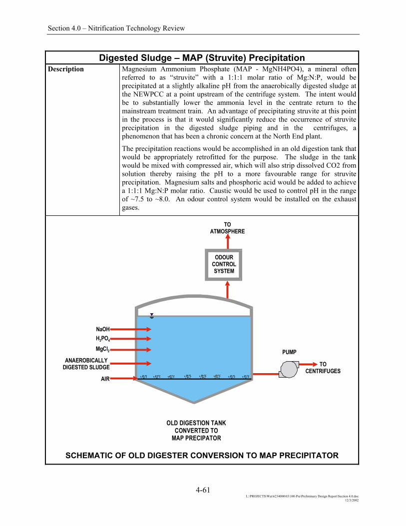
Section 4.0 – Nitrification Technology Review
Digested Sludge – MAP (Struvite) Precipitation Description Magnesium Ammonium Phosphate (MAP - MgNH4PO4), a mineral often
referred to as “struvite” with a 1:1:1 molar ratio of Mg:N:P, would be precipitated at a slightly alkaline pH from the anaerobically digested sludge at the NEWPCC at a point upstream of the centrifuge system. The intent would be to substantially lower the ammonia level in the centrate return to the mainstream treatment train. An advantage of precipitating struvite at this point in the process is that it would significantly reduce the occurrence of struvite precipitation in the digested sludge piping and in the centrifuges, a phenomenon that has been a chronic concern at the North End plant.
The precipitation reactions would be accomplished in an old digestion tank that would be appropriately retrofitted for the purpose. The sludge in the tank would be mixed with compressed air, which will also strip dissolved CO2 from solution thereby raising the pH to a more favourable range for struvite precipitation. Magnesium salts and phosphoric acid would be added to achieve a 1:1:1 Mg:N:P molar ratio. Caustic would be used to control pH in the range of ~7.5 to ~8.0. An odour control system would be installed on the exhaust gases.
OLD DIGESTION TANKCONVERTED TO
MAP PRECIPATOR
TO CENTRIFUGES
PUMP
H PO3 4
MgCl2
NaOH
ANAEROBICALLY DIGESTED SLUDGE
AIR
TO ATMOSPHERE
ODOUR CONTROL SYSTEM
SCHEMATIC OF OLD DIGESTER CONVERSION TO MAP PRECIPITATOR
4-61 L:\PROJECTS\Wat\6234000\03\100-Pre\Preliminary Design Report\Section 4.0.doc
12/3/2002
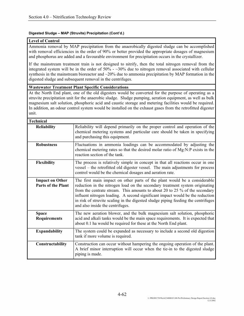
Section 4.0 – Nitrification Technology Review
Digested Sludge – MAP (Struvite) Precipitation (Cont’d.)
Level of Control Ammonia removal by MAP precipitation from the anaerobically digested sludge can be accomplished with removal efficiencies in the order of 90% or better provided the appropriate dosages of magnesium and phosphorus are added and a favourable environment for precipitation occurs in the crystallizer.
If the mainstream treatment train is not designed to nitrify, then the total nitrogen removal from the integrated system will be in the order of 50% - ~30% due to nitrogen removal associated with cellular synthesis in the mainstream bioreactor and ~20% due to ammonia precipitation by MAP formation in the digested sludge and subsequent removal in the centrifuges.
Wastewater Treatment Plant Specific Considerations At the North End plant, one of the old digesters would be converted for the purpose of operating as a struvite precipitation unit for the anaerobic sludge. Sludge pumping, aeration equipment, as well as bulk magnesium salt solution, phosphoric acid and caustic storage and metering facilities would be required. In addition, an odour control system would be installed on the exhaust gases from the retrofitted digester unit.
Technical Reliability Reliability will depend primarily on the proper control and operation of the
chemical metering systems and particular care should be taken in specifying and purchasing this equipment.
Robustness Fluctuations in ammonia loadings can be accommodated by adjusting the chemical metering rates so that the desired molar ratio of Mg:N:P exists in the reaction section of the tank.
Flexibility The process is relatively simple in concept in that all reactions occur in one vessel – the retrofitted old digester vessel. The main adjustments for process control would be the chemical dosages and aeration rate.
Impact on Other Parts of the Plant
The first main impact on other parts of the plant would be a considerable reduction in the nitrogen load on the secondary treatment system originating from the centrate stream. This amounts to about 20 to 25 % of the secondary influent nitrogen loading. A second significant impact would be the reduction in risk of struvite scaling in the digested sludge piping feeding the centrifuges and also inside the centrifuges.
Space Requirements
The new aeration blower, and the bulk magnesium salt solution, phosphoric acid and alkali tanks would be the main space requirements. It is expected that about 0.1 ha would be required for these at the North End plant.
Expandability The system could be expanded as necessary to include a second old digestion tank if more volume is required.
Constructability Construction can occur without hampering the ongoing operation of the plant. A brief minor interruption will occur when the tie-in to the digested sludge piping is made.
4-62 L:\PROJECTS\Wat\6234000\03\100-Pre\Preliminary Design Report\Section 4.0.doc
12/3/2002

Section 4.0 – Nitrification Technology Review
Digested Sludge – MAP (Struvite) Precipitation (Cont’d.)
Operational Ease of Operation This would be a new process for the operators to attend to and thus they would
need training on the technical concepts. The bulk chemical storage and metering equipment is typical of other equipment found at water and wastewater facilities and the operators should already have a certain degree of familiarity with such equipment. The odour control system installed on the exhaust from the retrofitted old digester tank would be new technology.
Ease of Maintenance
Additional maintenance work will be required to service the chemical metering equipment; however this type of work should be familiar to the plant’s maintenance staff.
Operator Safety Proper training will be required for the operators to handle the bulk chemicals required for the process.
Operator Environment
Under normal operation, no particular adverse environmental conditions should occur in the operator’s environment.
Environmental and Aesthetic Traffic There would be periodic bulk tanker truck receipts of magnesium salts,
phosphoric acid and alkali.
Noise There would be little additional noise associated with the system.
Visual The bulk chemical storage tanks would be visible.
Odours Presuming an odour control device would be installed on the exhaust gases from the retrofitted digestion tank, there should be little odour emission from the facility.
4-63 L:\PROJECTS\Wat\6234000\03\100-Pre\Preliminary Design Report\Section 4.0.doc
12/3/2002