Embed Size (px)
Citation preview

4-1
SECTION 4
Stormwater Quality, Erosion, and Sediment Control
4.1 Introduction The City has been identified by ADEM as an NPDES Stormwater Phase II community. One requirement of the Phase II program is to develop and implement a stormwater management program for construction and post-construction conditions. This section of the Manual is designed to provide resources to local agencies, engineers, developers, or others involved in erosion control and stormwater management in the City for helping to meet the NPDES Phase II requirements.
4.1.1 Erosion and Sediment Control Construction activities typically require the stripping of vegetation and/or removal of other existing stabilization from the ground surface, which exposes soil to rainfall energy and runoff velocities. As a result, significant soil erosion from construction sites can occur. The yield of soil erosion products from a construction site will depend on soil characteristics, climatic conditions, ground topography, and other site-specific factors. For this reason, varying amounts of sediment and turbidity will be generated and have a potential to discharge to Waters of the State, potentially violating State of Alabama Water Quality Standards. Sediment also can cause adverse impacts to offsite drainage conveyances and roads.
Construction activities that have the potential to affect the environment include, but are not limited to, land disturbance or discharges of pollutants associated with building, excavation, land clearing, grubbing, placement of fill, grading, blasting, reclamation, areas in which construction materials are stored in association with a land disturbance or handled aboveground; and other associated areas including, but not limited to, construction site vehicle parking, equipment or supply storage areas, material stockpiles, temporary office areas, and access roads. Construction activities of concern also include significant preconstruction land disturbance activities performed in support of NPDES construction activity including, but not limited to, land clearing, dewatering, and geotechnical investigations.
To protect water quality and to comply with the ADEM NPDES regulations (ADEM Admin. Code R. 335-6-12) and the City’s Erosion and Sediment Control Ordinance (ESC Ordinance), effective and applicable BMPs must be fully implemented to the maximum extent practicable. The operator must remediate any adverse impact that is caused by ineffective BMPs to maintain compliance with the requirements.

SECTION 4. STORMWATER QUALITY, EROSION, AND SEDIMENT CONTROL
4-2
4.1.2 Post-development Stormwater Quality Management Once completed, land development projects can have a long-lasting impact on water quality caused by the discharge of pollutants to nearby watercourses. These pollutants vary in type and concentration from place to place; but certain pollutants such as total suspended solids (TSS), petroleum-based contaminants, phosphorus, nitrogen, heavy metals, and fecal coliform bacteria are of particular concern. Water quality issues related to these non-point source pollutants generally are addressed through the implementation of post-development water quality BMPs. Various types of BMPs, as well as the benefits and drawbacks of each type and the methods to select them to address particular site concerns, are included in this section of the Manual.
The Manual will serve as a guide for city staff, consultants, and citizens to achieve consistency in the design and compliance of stormwater projects so that both growth and environmental guidelines can be followed effectively. Incorporating the guidelines contained in this Manual into applications and permits will aid in obtaining construction permits from the City.
4.1.3 Importance of Compliance Full compliance with both ADEM Phase II Stormwater regulations and the City’s ESC Ordinance are required to protect the quality of water and the quality of life in the Auburn area. Any noncompliance with the requirements constitutes a violation and is grounds for potential enforcement actions by ADEM, U.S. Environmental Protection Agency (EPA), and/or the City. An enforcement action could include, but not be limited to, a warning letter, notice of violation, consent or administrative order with monetary penalty, civil or criminal litigation, monetary fines imposed by the City, or an order to stop work on the site. In addition, holds may be placed on City Code inspections if erosion control measures are found to be non-compliant.
The ADEM Phase II Stormwater Regulations require that the stormwater runoff from construction activities be protective of water quality to the maximum extent practicable. To accomplish this goal, the regulations require that all site operators of NPDES Construction Sites develop and fully implement and maintain effective and applicable BMPs.
“NPDES Construction Sites” are construction activities that are required to obtain NPDES permit coverage under the ADEM regulations and are defined as the following:
• Construction activities with land disturbance that will disturb 1 acre or greater
• Construction activities that will disturb less than 1 acre but are part of a larger common plan of development or sale whose land-disturbing activities total 1 acre or greater.
• Construction or maintenance activities, irrespective of size, whose stormwater discharges have a reasonable potential to be a significant contributor of pollutants to a Water of the State, or whose stormwater discharges have a reasonable potential to cause or contribute to a violation of an applicable Alabama water quality standard as determined by a Qualified Credentialed Professional (QCP) or ADEM.

SECTION 4. STORMWATER QUALITY, EROSION, AND SEDIMENT CONTROL
4-3
Construction activities that will disturb less than 1 acre may not be required to obtain NPDES permit coverage, but are still required to implement the appropriate BMPs to protect water quality.
The continual assessment of the compliance status of an NPDES Construction Site is the responsibility of the construction site NPDES permit holder. This is accomplished through the full implementation of the Construction Best Management Practices Plan (CBMPP) and the inspection and maintenance activities required by the ADEM regulations and the City’s ESC Ordinance. These activities are discussed specifically in Section 4.3 of this Manual.
Because ADEM has primary regulatory authority of NPDES permitting of regulated construction activities in Alabama, permitting, compliance, and enforcement are all under the ADEM NPDES jurisdiction. Permitting and enforcement are under the ADEM Water Division. The field compliance unit is under the ADEM Field Operations Division. ADEM is responsible for the protection and preservation of water quality in Alabama by regulating activities that could lead to adverse impacts on the environment.
ADEM performs the following tasks as related to NPDES Construction Sites in Alabama:
• Review and approve or reject construction site NPDES construction stormwater permit coverage requests (Permitting Branch).
• Conduct routine compliance assurance site inspections in accordance with their guidelines (Field Operations).
• Conduct site inspections in response to citizen concerns (Field Operations).
• Review the compliance status of a construction site based on submitted documentation and field reports (Enforcement Branch).
• Issue enforcement actions when noncompliant issues are evident on the site that may result in any adverse impacts (Enforcement Branch).
Acting in the best interest of the community, the City developed local construction site erosion and sediment control regulations (ESC Ordinance) for construction activities within the jurisdiction of Auburn. The ESC Ordinance reinforces the Auburn goal to protect and preserve the local water resources and quality of life. The City developed the ESC Ordinance as a regulatory means to manage construction sites. The original Ordinance was developed by the Auburn, Lee County, Opelika, and Auburn University (ALOA) Citizen Advisory Committee in 2002 and was adopted by the Auburn City Council in July 2002. This ordinance provides guidelines for submitting CBMPPs, as well as for documenting City inspection and enforcement procedures. The City’s policies and procedures regarding erosion and sediment control inspection and enforcement are outlined in Section 4.3.3 of this Manual.
The City supports the ADEM permitting, compliance, and enforcement processes through the adoption of the ESC Ordinance and the City’s enforcement and site inspection efforts. The City’s response to post-storm events ensures that failed or
SECTION 4. STORMWATER QUALITY, EROSION, AND SEDIMENT CONTROL
4-4
deficient BMPs are corrected promptly. The City has adopted statewide standards for the design, construction, and maintenance of BMPs to provide a degree of uniformity in the requirements across the City. The City also routinely consults with ADEM to determine if there are any changes that need to be made to better support the ADEM efforts to protect the Waters of the State.
The City has not been delegated any authority to directly develop water quality standards. These are promulgated at the state and federal levels and managed through ADEM and EPA. The City works closely with these governing agencies when there appear to be deficiencies that may have resulted in adverse water quality or environmental impacts, as well as to learn ways to improve the City’s program to support the Auburn area.
4.1.3.1 Protecting Water Quality during Construction It is the responsibility of the developer or operator to retain or employ a qualified professional to design all aspects of the proposed project or development and a QCP to plan, design, and certify the CBMPP for the project. The QCP shall be responsible for preparing a CBMPP using good engineering practices that will result in specific strategies to protect water quality. The CBMPP must use the basic design principles available in the Alabama Handbook for Erosion Control, Sediment Control and Stormwater Management on Construction Sites and Urban Areas (Alabama Handbook), the City’s standard erosion and sediment control details (Appendix A), and other recognized BMP documents. The Alabama Handbook can be downloaded from the ADEM website. As part of its review, the City is responsible for determining if the QCP has considered the necessary measures in selecting and designing the site-specific BMPs. If there are any CBMPP deficiencies noted by the City, comments will be provided. This review will be similar to staff reviews of other aspects of the design, including streets and water and wastewater infrastructure, and is discussed in more detail in Section 4.2 of this Manual.
4.1.3.2 Avoiding Enforcement Actions by ADEM, EPA, and the City of Auburn To avoid enforcement actions and to protect water quality, the operator must take all actions necessary to achieve and maintain regulatory compliance at the site at all times. Regulatory enforcement by ADEM, EPA, and the City may include monetary fines and associated costs that can be significant and detrimental to the financial well-being of a development. NPDES permit holders can avoid enforcement actions by performing the following:
• Retain the services of a QCP who will prepare a CBMPP that will protect water quality.
• Fully implement the CBMPP for the project.
• Perform the regular inspections and corrective actions at the intervals and within the time frame required by the ADEM regulations and the City’s ESC Ordinance.
• If the CBMPP is deficient, communicate and work with the QCP so that the CBMPP can be revised and the additional BMPs installed in a timely manner.
SECTION 4. STORMWATER QUALITY, EROSION, AND SEDIMENT CONTROL
4-5
Because enforcement actions by ADEM, EPA, and/or the City could be in the form of fines and/or stop-work orders, the cost of noncompliance is high.
4.1.4 Common Needs on Construction Sites The common characteristics of all construction and development projects include the need to remove trees and/or other forms of vegetation. This action causes the underlying soils to be exposed to precipitation, resulting in a greater chance for erosion to occur. If allowed to occur without any controls, the products of erosion and sedimentation can enter Waters of the State and offsite conveyances and cause water quality and/or hydraulic impacts to occur. It is critical that the appropriate BMPs be designed and implemented using good engineering practices for each specific construction site to protect water quality and to comply with the ADEM regulations and the City’s ordinances. Common needs of all construction sites are discussed in this section.
4.1.4.1 Good Planning To ensure compliance with applicable regulatory requirements, the CBMPP must address effective measures that are to be implemented and maintained to prevent and/or minimize the discharge of all sources of pollution (i.e., sediment, trash, garbage, debris, oil and grease, chemicals, materials, etc.) to Waters of the State in stormwater runoff. Good planning is a crucial element in any CBMPP. Preconstruction planning should consider site soil types, steepness and stability of cut-and-fill slopes, precipitation patterns that are typical for the area, preservation of existing vegetative cover, and site-specific and effective erosion prevention, along with site-specific and effective sediment control.
The operator shall incorporate basic planning principles related to erosion prevention and sediment control for all construction sites in the City regardless of the size of the project or its registration status. These principles should be discussed in the CBMPP and should be implemented to address the following minimum site planning goals:
• Preconstruction gathering and analysis of information to plan and conduct the construction activity in such a manner to prevent or avoid potential discharges or problems; know where all the stormwater receptors and streams are located and locate regulated activities accordingly.
• Identify and divert upslope water around the disturbance areas.
• Limit the exposure of disturbed areas to precipitation to the shortest amount of time possible.
• Use a phased development plan when possible to minimize the amount of surface area that is disturbed at any one time.
• Identify the clearing limits and provide barriers and/or other methods to confine disturbance activities to that area.
• Show all applicable buffers on the CBMPP and preserve them throughout the construction period.
SECTION 4. STORMWATER QUALITY, EROSION, AND SEDIMENT CONTROL
4-6
• Immediately correct any deficiencies in BMP implementation and maintenance.
• Incrementally implement stabilization practices as soon as possible following final grading.
• Give special attention to critical areas such as slopes because they are difficult to stabilize.
• Perform site inspections to ensure BMP effectiveness.
4.1.4.2 Site-specific Construction Best Management Practices Plan Each NPDES Construction Site must have a site-specific CBMPP that has been prepared and certified by a QCP. The CBMPP shall identify the applicable and effective BMPs that must be implemented and maintained to meet the requirements of the ADEM regulations and the City’s ESC Ordinance. The CBMPP and the individual BMPs shall meet or exceed the following technical standards and guidelines:
• The Alabama Handbook • ADEM’s regulations and the City’s ESC Ordinance and standard details
The permit holder of an NPDES Construction Site is responsible for fully implementing the CBMPP, which shall be maintained at the project site and shall describe in detail the structural and/or nonstructural practices and management strategies that will be implemented and continually maintained to prevent or minimize the discharge of all sources of pollutants. The CBMPP shall be updated as necessary to address any potential or observed deficiencies.
4.1.4.3 CBMPP Inspection and Maintenance Permit holders shall ensure that their construction activities are evaluated continually to ensure compliance with the provisions of the ADEM regulations and the City’s ordinance. All NPDES Construction Site operators shall ensure that their construction activities are regularly inspected by a Qualified Credentialed Inspector (QCI), QCP, or a qualified person under the direct supervision of a QCP, as applicable, to ensure compliance with the provisions of the ADEM requirements. Each NPDES Construction Site permit holder shall fully implement and maintain a comprehensive CBMPP in accordance with the requirements of the ADEM regulations and the City’s ordinance until the regulated activities have ceased and the registration has been properly terminated.
All required site inspections shall be noted in the CBMPP and shall be performed and documented as required by the ADEM regulations. A copy of all required site inspection reports should be submitted to the City’s Watershed Division, WRM Department, 1501 West Samford Avenue, Auburn, Alabama, 36832. Corrective actions on deficient BMPs shall be completed within the timeframe required by the ADEM regulations and/or the City’s regulations.
SECTION 4. STORMWATER QUALITY, EROSION, AND SEDIMENT CONTROL
4-7
4.1.4.4 Erosion Prevention Emphasis It is strongly encouraged that permit holders on construction projects in the Auburn area place emphasis on the use of erosion prevention on their sites. Erosion prevention strategies could include, but not be limited to, maintaining stabilization, limiting the amount of area that is cleared at one time, and limiting the duration of soil exposure and other erosion prevention strategies. By placing an emphasis on erosion prevention, a smaller amount of erosion products will be generated, resulting in a greater chance for success in protecting water quality.
4.1.5 City of Auburn Requirements and Special Conditions under the Municipal Separate Storm Sewer System Designation by ADEM
The Phase II regulations are an extension of the Phase I Stormwater Regulations and became effective in March 2003. The City came under the Phase II Stormwater regulations because of the overall population of Auburn, Opelika, and surrounding Lee County. Under its General Permit, the City is required to perform monitoring of water quality within its MS4 that discharge to impaired waters and/or to a water for which a TMDL has been approved by the EPA. When the City began its Phase II Stormwater Program, coordination and implementation of the individual stormwater management program was the responsibility of the City‘s Public Works Department. In October 2005, management of the City’s stormwater program was transitioned from the Public Works Department to the City’s Water and Sewer Department under a newly created Watershed Division. Coinciding with the formation of the Watershed Division was the renaming of the City’s Water and Sewer Department to the WRM Department. The intent of the move was to manage water supply operations, wastewater operations, and stormwater operations based on a watershed perspective for all components that affect water quality within areas of jurisdiction for Auburn, including construction stormwater.
4.1.5.1 Phase II General MS4 Permit–Construction Activities Under the federal Phase II Stormwater regulations, provisions are provided that require a permitting authority to implement the minimum control measures for the Municipal Separate Storm Sewer System (MS4). If the permitting authority provides this recognition, then the MS4 is not required to include that minimum control measure in its Program. ADEM Administrative Code Chapter 335-6-12 implements a statewide construction stormwater regulatory program that meets NPDES requirements for construction activities. Additionally, under General Permit ALG040000, it is specifically stated that this General Permit requires an MS4 to implement a local construction stormwater control program, but may rely upon ADEM for enforcement. City regulations do not supersede the ADEM regulations and are intended to support the ADEM efforts.
4.1.5.2 Erosion and Sedimentation Control Policy and Ordinance To fulfill its goal to provide additional protection to the Waters of the State in the Auburn area, the City has implemented an ESC Ordinance and Policies and Procedures

SECTION 4. STORMWATER QUALITY, EROSION, AND SEDIMENT CONTROL
4-8
dealing with its overall Stormwater Management Program; construction stormwater is included under this program.
4.1.5.3 Tier 1 and Priority Waters–Construction Activities ADEM considers Tier 1 Waters related to Construction Activities as those waters that are affected by construction activities and that: 1) do not meet use classification water quality standards; 2) have use classifications less than Fish and Wildlife; or 3) have implemented total maximum daily loads (TMDLs). These waters are listed in the ADEM Construction Stormwater TMDL and 303(d) Listed Tier 1 Water bodies, which is periodically updated by ADEM and provided at www.adem.state.al.us under the Water Division. Moore’s Mill Creek (AL03150110-0301-400) has the following use classifications: 1) Swimming; and 2) Fish and Wildlife. However, it is listed on the ADEM Construction Stormwater TMDL and 303(d) Listed Tier 1 Waterbodies for siltation from its source to Chewacla Creek. The sources that have caused this sediment listing are land development and urban and storm sewers.
For priority construction sites, which include any site that discharges to (1) a waterbody which is listed on the most recently EPA approved 303(d) list of impaired waters for turbidity, siltation, or sedimentation, (2) any waterbody for which a TMDL has been finalized or approved by EPA for turbidity, siltation, or sedimentation, (3) any waterbody assigned the Outstanding Alabama Water use classification in accordance with ADEM Admin. Code r. 335-6-10-.09, and (4) any waterbody assigned a special designation in accordance with ADEM Admin. Code r. 335-6-10-.10, the CBMPP must be submitted to ADEM for review along with the NOI. Per the National Pollutant Discharge Elimination System General Permit ALR100000 (Alabama Construction General Permit), no land development shall commence within a Priority Watershed, as defined above, without (1) an approved ADEM Construction Stormwater Permit or (2) proof that an NOI has been submitted and received by ADEM, and ADEM has failed to respond within 30 days of that receipt.
SECTION 4. STORMWATER QUALITY, EROSION, AND SEDIMENT CONTROL
4-9
4.2 City of Auburn Erosion and Sedimentation Control Permitting
4.2.1 Erosion and Sedimentation Control Ordinance The City’s ESC Ordinance and related Policy and Procedures identify the permitting steps involved for construction activities as related to erosion and sediment control. The City’s review process for permitting includes the following reviews:
• CBMPP review • Stream buffer review • Steep slope review
For the protection of water quality and other area resources, these reviews are conducted by the City for all land disturbance projects. Review comments will be provided to the permit holder and must be corrected before any construction activities are begun.
4.2.2 City of Auburn Erosion and Sedimentation Control Guidelines and Requirements
The City’s desire to protect water quality and the quality of life for residents of the Auburn area has led it to develop regulations and documents for use by local developers and contractors during construction activities. The ordinances and documents that describe the guidelines and requirements are as follows:
• Erosion and Sedimentation Control Ordinance • Illicit Discharge Ordinance • City of Auburn Stormwater Management Program, Policies and Procedures • Summary of Auburn’s Stormwater Program–Erosion and Sediment Control
These and other related documents are available through the City and provide the City’s requirements for development at construction sites.
4.2.3 City of Auburn Design and Construction Standards The following is a list of the City’s major design and construction standards and policies related to erosion prevention and sediment control on all construction sites:
• A CBMPP shall be developed for any construction activity where soil is disturbed to the point at which Waters of the State or adjoining property could possibly be affected by sediment transport. The CBMPP shall comply with applicable ADEM regulations and shall contain sufficient information to describe the structural, nonstructural, and planning procedures that are to be used to prevent erosion.
• Minimize sediment transport from the site and address potential hydrologic impacts resulting from the activity.
SECTION 4. STORMWATER QUALITY, EROSION, AND SEDIMENT CONTROL
4-10
• Erosion prevention and sediment control measures shall be incorporated prior to or concurrent with all clearing and grubbing construction activity and prior to grading and utility construction activity, and shall be maintained to maximize performance and efficiency during construction. The CBMPP may be revised and control measures altered during construction as necessary to comply with the City’s ESC regulations.
• The City shall perform monthly inspections (at a minimum) of active construction sites and shall at times perform water quality monitoring to assess the impacts of an active construction site on the City's stormwater conveyance system and/or waterways. Any deficiencies shall be documented and reported to the contractor and/or developer/operator for immediate attention and remediation. If the water quality monitoring indicates that the current BMPs are insufficient because of a rise in the water turbidity by 50 nephelometric turbidity units (NTUs) or greater, the contractor and/or developer/operator shall be notified to revisit the CBMPP to improve the performance of BMP measures or add to measures that currently are installed.
• All CBMPP BMPs shall be inspected monthly at a minimum or within 48 hours following a 0.75-inch or greater rainfall within any 24-hour period. Copies of the ADEM inspection report for applicable sites shall be submitted to the City‘s WRM Department. Maintenance, repair, and improvements to the CBMPP control measures shall be completed within the timeframe outlined in the inspection report.
• A construction exit pad (CEP) shall be installed at all points of ingress or egress to the site, as approved by the City, and shall be maintained at all times to minimize the transport of sediment from construction sites to City public streets. No more than one CEP is allowed per construction site unless otherwise approved by the City. For construction sites which cannot install and maintain a 20’x50’ CEP per the COA Standard Details, or the CEP is determined by Water Resource Management or Public Works to be ineffective or inadequate for site conditions, a Wheel Wash System or approved equivalent shall be used.
• Erosion control blankets and netting and/or a flocculant such as polyacrylamide (PAM) shall be used on steep slopes (greater than 3 horizontal: 1 vertical [3H:1V]) and in channels to stabilize soils while establishing vegetative cover. The City may require the use of flocculants on developments that discharge directly to the water bodies and in other areas as deemed necessary by the City.
• All bare areas shall be mulched immediately following the completion of initial grading practices. All bare areas shall receive temporary seeding and mulching when the area has been graded for 5 calendar days and will not be worked for more than 13 calendar days.
• All erosion and sediment control measures shall be designed and maintained in accordance with the Alabama Handbook (latest version) and the City’s standards.
• Erosion and sediment control BMPs shall be designed and installed according to their intended application. In the event BMPs are misapplied, they shall be replaced immediately upon notification by the QCI and QCP or City.

SECTION 4. STORMWATER QUALITY, EROSION, AND SEDIMENT CONTROL
4-11
• Buffer zones shall be clearly marked such that no excavation shall occur within this zone other than what is prescribed for the construction of approved utilities and access routes (roads, streets, greenways, etc.); any and all such work shall be performed in a workmanlike manner as to minimize impacts within the reasonable construction limits.
• Any work outside the boundaries of the construction limits or buffer zones is not allowed. The developer/operator shall modify the CBMPP prior to disturbance and receive approval from ADEM and the City prior to any work beginning outside the boundaries of the construction limits or buffer zones.
• Permits shall be obtained from ADEM and the USACE, as applicable, for any land disturbance activity. Any work performed or impacts made outside the boundaries of approved wetland and stream impact zones shall be reported to ADEM and/or the USACE.
• Each day on which there is activity at the construction site, the operator, a QCI, a QCP, a qualified person under the direct supervision of a QCP, other qualified consultant, or other qualified persons shall visually observe that portion of the construction project where active disturbance, work, or construction occurred and report any apparent BMP deficiencies observed to the operator, QCP, or QCI for maintenance.

SECTION 4. STORMWATER QUALITY, EROSION, AND SEDIMENT CONTROL
4-12
4.3 CBMPP Approval, Implementation, Inspection, and Maintenance Requirements
4.3.1 Submittals For NPDES construction sites, the following submittals to the City are required as part of the City’s permitting and review process:
• Completed ADEM Notice of Intent • CBMPP • ADEM Notice of Receipt of Registration • For sites within the Moore’s Mill watershed, a copy of the permit or approval letter
from ADEM is required.
As described in Section 4.3.1.1 of this Manual, the City has a formal review and approval process for all CBMPPs.
4.3.1.1 Review and Approval of Construction Best Management Practices Plans Watershed Division personnel will review the CBMPP submitted for each individual development and will provide written comments to the engineer and/or QCP regarding the CBMPP in accordance with the City’s DRT, which is covered in a previous section of this Manual. Generally, the developer’s QCP (as defined by ADEM) is responsible for designing, planning, and certifying the CBMPP BMPs that will ensure protection of Waters of the State and ensure compliance with the City’s rules, as well as compliance with the ADEM regulations. The City has adopted the statewide standards to encourage uniformity in CBMPP design, implementation, and maintenance.
As described previously, the CBMPPs shall be submitted to the City by the QCP, along with other applicable engineering drawings and specifications for the project. The CBMPP will be reviewed as part of the City’s plan review process by Watershed Division staff to ensure that minimum criteria are met. City staff will issue comments to address deficiencies or areas of concern with the submitted plan. Comments generally will be emailed to the City’s Public Works Department and subsequently mailed, along with additional plan review comments, to the engineer of record.
Once all comments have been addressed, a preconstruction meeting will be scheduled by the City’s Public Works Inspection Division Manager. The developer, contractor, engineer of record, QCP, and any other applicable parties should attend the preconstruction meeting.
Following the preconstruction meeting, an Erosion and Sediment Control (ESC) Permit will be issued to the permit holder by the Inspection Division Manager provided that the permit holder has provided documentation to the City showing that the NOI has been submitted to ADEM. For priority construction sites, a copy of the NPDES Permit must be provided to the City prior to issuance of the ESC Permit. Any applicable USACE permits also should be provided to the City prior to issuance of the ESC Permit. This ESC Permit allows the contractor to begin implementation of the site CBMPP, and then to begin conducting clearing and grubbing operations. A Grading
SECTION 4. STORMWATER QUALITY, EROSION, AND SEDIMENT CONTROL
4-13
and Utility Permit will not be issued until the CBMPP has been fully implemented by the permit holder, and has been inspected and approved by the City.
In addition to the normal items that are reviewed in the CBMPPs, the Watershed Division personnel specifically review two special areas: 1) stream buffers; and 2) steep slopes. The City’s CBMPP stream buffer review is intended to ensure that the CBMPP has included requirements of the City‘s stream buffer regulations, Article IV, Section 413, of the City Code. The City may use its Geographic Information System (GIS) Watershed Delineation Tool in situations where the buffer shown is in question to ensure that the applicable buffers have been applied. The purpose of this review is for staff to ensure that proper identification of stream buffers and buffer requirements are documented on the CBMPP, subdivision plats, and other site plans and that the proper delineation and documentation are provided on engineering plans.
The second specific area of concern during the City’s CBMPP review involves steep slopes, which should be designated as critical areas and should be noted on the CBMPP. To encourage the uniform establishment of stabilization, steep slopes require special attention and treatment. These must be specifically identified in the CBMPP. Steep slope restabilization shall begin immediately following final grading. Typical BMPs may include, but not be limited to, slope tracking, installation of geofabrics and other BMPs that are specifically applicable to steep slope critical areas. The Watershed Division personnel will review the CBMPP and analyze GIS topography of steep slope areas on developments to ensure that the designer has included an evaluation and requirements of the City’s steep slope regulations, as shown below, and included appropriate delineation and documentation on the plat and plan, and appropriate BMPs in the CBMPP to promote the management of any land disturbance in an area where steep slopes exist. The City’s steep slope regulations include the following requirements:
• Areas subject to steep slope restriction shall be indicated on a map maintained by the Information Technology Department and available to the public.
• Steep slope areas within 600 feet of the top of any perennial or intermittent stream shall be preserved in their natural state whenever possible. Where construction of roads, building, driveways, or infrastructure cannot be avoided, disturbance shall be kept to a minimum, and in no case, shall it exceed the following limits:
A. Fifteen- to 30-percent slopes: Site disturbance shall be minimized to the maximum extent practicable. The site erosion and sediment control plan should provide BMPs to minimize erosion of these slope areas during development.
B. More than 30-percent slopes: No more than 25 percent of such areas containing 1 acre or more of continuous slopes shall be developed and/or regraded or stripped of vegetation and the slope area to be developed, regarded, or stripped of vegetation shall be shown on the plat or plan. If the application of these steep slope regulations results in the loss of buildable area on a lot, mitigation measures in accordance with Section 413.10 of the Zoning Ordinance may be proposed by the engineer of record and considered by the City’s WRM Department to allow for disturbance within these slope areas.

SECTION 4. STORMWATER QUALITY, EROSION, AND SEDIMENT CONTROL
4-14
C. Steep Slopes in a Stream Buffer: No slopes greater than 30 percent that lie within a stream buffer shall be developed and/or regraded or stripped of vegetation unless approved in accordance with Sections 413.09 through 413.12 of the City’s Zoning Ordinance.
4.3.1.2 Design Calculations The QCP will develop design calculations to provide supporting documentation for the CBMPP. Design calculations shall be in accordance with the Alabama Handbook (latest revision) and shall be submitted to the City for review and comment.
4.3.2 Checklists The permit holder shall be aware of the standard checklists that the City will use to assess completeness of a development design and items that will be reviewed by the City while performing site inspections. The major checklists are described below.
4.3.2.1 City of Auburn Site Development Plans Submittal Checklist The plan submittal checklist deals directly with the CBMPP and must be submitted with every set of engineering construction plans for site developments. All items on the checklist shall be addressed. This checklist is not intended to be all-inclusive, and fulfillment of this checklist does not alleviate the obligation of the permit holder to protect Waters of the State and to meet all related City codes, regulations, ordinances, and specifications. The purpose of this checklist is to facilitate a more efficient plan review process for the designer and the review team. The CBMPP requirements are outlined in the checklist found in Appendix B of this Manual and may be in addition to the CBMPP requirements in the ADEM regulations:
• Used a phased plan when applicable.
• Show clearing limits.
• Show stream and wetland buffers. Drainage basin of stream should be delineated from the commencement point of the stream, to the point that it leaves the property. Basin area determines buffer widths (see Zoning Ordinance).
• Provide an ESC legend.
• Identify project site identification sign location and provide project rain gauge onsite.
• Provide a CEP (minimum 20 feet x 50 feet). Use #1 stone with geotextile fabric underneath. Use one CEP per site at any given time.
• All silt fencing shall be Type “A” (wire-reinforced, metal-staked, trenched) or C-POP.
• Hay bales may not be used as stand-alone inlet protection. They can be used in conjunction with silt fence or other sediment barriers.
• Use rock check dams, wattles, or silt fence check dams (rather than hay bales) where applicable.
SECTION 4. STORMWATER QUALITY, EROSION, AND SEDIMENT CONTROL
4-15
• Design and show outlet protection at all discharges.
• Show curb inlet protection devices (no stand–alone hay bales).
• Slopes greater than 3:1 require erosion control blankets. Specify types of blankets being used.
• Show all sediment basin location, filter volumes, and sediment volumes.
• Submit copies of all sediment storage design calculations.
• Attach City standard erosion and sedimentation control details (Appendix A).
• Include the following notes on the ESC or CBMP Plans:
a. Any area that has been disturbed and will remain so for more than 13 days shall be seeded and mulched within 5 days of being disturbed.
b. Additional BMPs may be required by the QCP and/or City over the course of the project to minimize sediment release from the site
c. All BMPs shall be designed and installed in accordance with the Alabama Handbook and the City’s standard erosion and sediment control details.
d. The use of floc-blocks, PAM, or other settling enhancement materials may be required by the QCP or the City during the course of construction to minimize turbidity and sediment release from the site.
4.3.2.2 City of Auburn ESC Inspection Checklist This checklist is used by the City inspectors to guide and document site inspection activities. Its specific use is discussed in the Inspection section.
4.3.3 City of Auburn Inspection and Enforcement Program The City staff has developed an inspection and enforcement strategy that promotes compliance with the City’s erosion and sediment control regulations by monitoring sites in a proactive manner and responding to deficiencies with the appropriate action to ensure that the City’s standards are being met to the maximum extent practical. The City’s program does not supplement, but supports, the ADEM construction site inspection program in that a majority of issues and deficiencies are resolved before any significant water quality impacts have occurred.
The City requires developers and/or contractors to develop and fully implement a CBMPP on all NPDES Construction Sites to minimize erosion and sedimentation impacts on the surrounding environment and natural resources. Although CBMPPs are only required for NPDES Construction Sites, carefully planned Erosion and Sediment Control Plans are required for all sites where land is disturbed. Actual selection and installation of BMPs will depend on the specific needs of each individual site characteristics and will be displayed and marked on the CBMPP, which is approved by City personnel prior to site clearing and development. Inspection comments and recommendations will be based on the measures outlined in the CBMPP.

SECTION 4. STORMWATER QUALITY, EROSION, AND SEDIMENT CONTROL
4-16
Upon issuance of the City’s ESC Permit, the contractor is authorized to begin installing erosion and sediment control measures at the site. Prior to beginning any clearing and grubbing activities, appropriate BMPs must be implemented. Once all BMPs have been fully implemented, the contractor or operator should schedule an initial CBMPP walk-through inspection with the Watershed Division Manager and/or Public Works Inspection Division Manager. The Division Manager will then conduct a walk-through inspection of the BMPs onsite in accordance with the approved CBMPP. If all measures are satisfactorily installed, the Public Works Inspection Division Manager will issue a Grading and Utility Permit to the contractor authorizing the contractor to begin grading operations and utility installation onsite. If the BMPs onsite have not been satisfactorily installed in accordance with the CBMPP or other deficiencies are noted, the Division Manager will notify the contractor of the issues onsite and will schedule a follow-up inspection prior to issuing the Grading and Utility Permit.
4.3.3.1 City of Auburn Construction Site Inspections In addition to the ADEM inspection requirements, the City staff will be performing certain other inspections and compliance determinations for each site, using the inspection checklist provided in Appendix B. Even with these additional inspections, it is still the operator’s sole responsibility to continually assess the compliance status of each site. The City’s and the ADEM site inspections are Compliance Assurance Inspections. The timing and general processes of construction stormwater inspections within the City’s jurisdictions are summarized below:
• Routine inspections will be made on a monthly basis to determine site compliance with City Ordinances and the CBMPP.
• Rainfall inspections will begin within 48 hours after each rainfall event that equals or exceeds 0.75 inch in any 24-hour period to determine site compliance with City ordinances and the CBMPP.
• The Watershed Division Manager will determine the schedule of inspections.
• Documentation of inspection, including inspection report, photographs (if applicable), and letter to permit holder will be emailed and filed within 48 hours of inspection.
• When major deficiencies are observed upon inspection, the Watershed Division Manager shall coordinate with the Stormwater Coordinator to determine if a Notice of Violation (NOV) is warranted.
• Inspection reports shall be entered into the City’s Construction Site Database within 1 month of the inspection.
The following general guidelines are used by the City when performing CBMPP inspections for construction sites.
The City’s inspector shall use commonly accepted procedures and practices for conducting each inspection. Site inspections will include a review of existing BMPs to determine effectiveness and to develop recommendations to modify, add, or improve existing measures.
SECTION 4. STORMWATER QUALITY, EROSION, AND SEDIMENT CONTROL
4-17
Each inspection sheet will note the following:
• Date, time, and inspector • Development or construction site name, name of developer, contractor or operator,
and location of site
Site deficiencies will be noted by the inspector on the inspection report and/or letter. Additionally, the inspector will note whether a BMP requires maintenance, as well as including any relevant comments or considerations. All deficiencies should be documented on the inspection form and by digital photograph.
City staff will inspect the installation and maintenance of the BMPs. However, it is the sole responsibility of the operator to fully inspect the construction site, to make continual assessments of the compliance status, and to identify corrective actions for the BMPs that are needed to protect Waters of the State and offsite conveyances. The City does not direct work, but points out deficiencies and takes necessary enforcement actions when deficiencies are not addressed in a timely manner.
Site inspections will determine and document whether uncontrolled releases of sediment or turbid water have occurred, as well as what corrective actions are necessary for proper control. If it is determined that significant releases of sediment have occurred and/or there is evidence of water quality impairment as a result of the deficiencies, then the NPDES permit holder shall provide a 24-hour verbal and 5-day written Noncompliance Notification Report (ADEM Form No. 501) to ADEM and the City. The Watershed Division Manager also may immediately notify ADEM of these deficiencies.
The Inspector shall communicate any major deficiencies noted during the inspection so that issues may be addressed while a report is prepared. The compliance inspection and monitoring processes are self-monitoring in that the operator must have on his staff or hire a QCP to design, prepare, and certify the CBMPP. A QCP, qualified person under the direct supervision of a QCP, or a QCI must inspect the BMPs for proper installation and maintenance. ADEM inspection reports (Stormwater Inspection Report and BMP Certification [ADEM Form No. 500]) must be prepared and signed by the inspector and placed in the file ready for ADEM or the City’s review within 15 days of the date of the inspection. If noncompliant issues are found during the routine inspections, the QCP is required to provide ADEM with a verbal notification within 24 hours of becoming aware of the noncompliant BMP and/or discharge and then provide ADEM, within 5 days, a written Stormwater Noncompliance Notification Report that fully describes the noncompliant issue(s), the period of the noncompliance, and the measures taken and/or being taken to correct the noncompliant condition and to keep it from recurring.
In addition to the BMPs and other strategies provided in the Alabama Handbook, the City has identified certain control measures for inspection emphasis. Also, the City has prepared standard details for certain BMPs that are accepted by the City and used frequently on projects within the City’s jurisdiction. These standard details are provided in the two Erosion Control drawings provided in Appendix A. The City’s inspection emphasis is provided herein for certain construction BMPs and strategies.
SECTION 4. STORMWATER QUALITY, EROSION, AND SEDIMENT CONTROL
4-18
4.3.3.2 Sediment Control Structures Appropriate BMPs must be selected by the QCP and will vary by site. Typically, sediment control devices will serve as the second line of defense to protect water quality and are intended to minimize sediment from entering waters of the state or Waters of the United States or adjacent parcels of property. Sediment control structures are effective in providing a location to collect sediment-laden stormwater and to remove sediment by filtering or settling. In general, inspectors should observe the site overall, paying special attention to areas of existing or potential erosion and accumulation of sediment.
Sediment control structures should include the following, at a minimum:
1. Sediment traps–Typically, these are small, temporary structures that are removed when construction activities have been completed. Overall condition should be assessed during inspections (stabilization of trap slopes, buildup of sediment, inlet structures, etc.). Required volume calculations for sediment traps are based solely on 3,600 cubic feet per acre of drainage area.
2. Filter structures and/or Skimmer Device–Should be clean and functioning properly.
3. Detention/retention pond–See sediment trap comments. Detention and retention ponds are retrofitted for sediment storage to serve as sediment basins until the site is completely stabilized, provided that proper outlet and filter structures are in place.
4. Outlet structure–Overall condition and proper installation.
5. Flocculants (logs blocks PAM)–Assess the need for flocculants. Is the water flowing through the outlet structure still significantly turbid? Check slopes and other critical areas to determine the need for additional stabilization.
6. Discharge headwalls–Overall condition (proper installation, stabilization, and outlet protection): Are stilling basins or energy dissipaters required to maximize efficiency of the structures?
7. Sediment Forebays and Baffles–Evaluate the need for sediment forebays and/or baffles in the basin. Baffle design requirements can be found in a publication produced by the North Carolina State Cooperative Extension Service (Using Baffles to Improve Sediment Basins, Publication No. AG-439-59) and calculations must be submitted to the City’s WRM Department for review. Baffles are required if the basin cannot be designed in accordance with the City’s 3:1 length:width ratio requirement. Forebays and/or baffles can be used in conjunction with flocculants to minimize turbidity leaving the basin. If forebays and/or baffles are in place, check the need for maintenance of the structures.
4.3.3.3 Sheet Flow Barriers The City’s Ordinances require that measures be taken to control erosion and runoff of disturbed soil areas and open areas that are affected by development and construction activities. Furthermore, City Ordinances require that disturbed soil that is not to be
SECTION 4. STORMWATER QUALITY, EROSION, AND SEDIMENT CONTROL
4-19
worked for at least 13 days be stabilized with seed and mulch within 5 days of initial disturbance.
Inspections of sheet flow barriers should include, at a minimum, the following:
1. Silt fences erected to control sheet water flow–Assess for proper installation, correct type of silt fence, breached or damaged silt fence, etc.
2. Seeding, mulching, chemical stabilization (PAM, hydro seeding, etc., and other methods of stabilization for exposed areas to encourage vegetative growth).
3. Daily mulching may be required when utilities are constructed adjacent to or within stream buffers.
4. Sediment and erosion control blankets (ECBs) should be installed on all slopes greater than 3H:1V. The engineer of record or QCP shall be responsible for designing and specifying the correct type of ECB for the slope and soil in question in accordance with the Alabama Handbook. The contractor or operator shall be responsible for installing the ECBs in accordance with the Alabama Handbook guidelines and manufacturers’ recommendations.
4.3.3.4 Channel Check Structures Drainage channels, both natural and manmade, shall be inspected to ensure that appropriate BMPs have been implemented to control erosion and sedimentation impacts from stormwater runoff. In no case shall BMP measures be placed within Waters of the State and or Waters of the United States unless otherwise permitted through a site-specific USACE Section 404 permit.
Inspections of channel check structures should include the following:
1. Rock check structures–Proper installation, cleaning, and/or maintenance, etc. 2. Silt fence checks–Proper installation, cleaning, and/or maintenance, etc.
4.3.3.5 Stream Bank Stabilization Special considerations exist for streams that flow through areas being developed. Stabilization of stream banks is critical for preventing further erosion, as well as preventing unnecessary damage to the environment due to discharges into the stream from construction activities. It is important for inspections to note the effect of all the CBMPP measures on streambeds, especially when considering issues of stream bank stabilization.
Specifically, inspections will cover the following stream bank stabilization issues:
1. Chemical stabilization (use of PAM, hydro seeding, etc.) of banks. Is coverage adequate and complete?
2. Rip-rap–Is sizing and installation appropriate? Is filter fabric underlining required and has it been installed?
3. Stream crossing and protection–Assess the installation of or the need for installing additional CBMPP measures such as silt fences, erosion and sediment control blankets, etc.
SECTION 4. STORMWATER QUALITY, EROSION, AND SEDIMENT CONTROL
4-20
4.3.3.6 Inlet Protection All storm drain inlets shall be protected against the entry of sediment and silt at all times. Because conditions may change throughout the development process, modifications to these barriers are to be expected to be implemented. Inlet protection BMPs should be appropriate for the type of inlet and surrounding areas.
Inspections for inlet protection BMPs should include the following, at a minimum:
1. Silt fences or other prefabricated inlet barriers such as molded polyethylene cage with filter fabric at storm drain inlets. The use of hay bales for inlet protection is strictly prohibited unless used in conjunction with silt fencing around the inlet.
2. Curb inlet protection to include gravel filter bags or other approved devices.
4.3.3.7 General Site Measures Inspections of general site BMPs and other management strategies typically entail observation of good grounds keeping and also consider how the overall site is affecting the surrounding areas. General site measures inspections will include inspections of the following:
1. General maintenance of construction entrances and buffer areas–Sediment and debris tracked by vehicles onto roadway will wash into stormwater systems and may cause hazardous road conditions for the general public. Does the construction entrance consist of ALDOT No. 1 course aggregate with geofabric? Is the construction entrance the proper length and width? Should the contractor consider lengthening or widening the construction entrance?
2. Posting of all applicable federal, state, and local permits in a visible location near the construction entrance and clear marking of construction limits and buffer areas.
3. Rain gauges should be posted onsite in a visible location near the construction entrance.
4. A designated and controlled concrete washout area is required on all construction sites utilizing concrete.
4.3.3.8 Inspection Report and Follow-up Documentation Inspection report checklists will be completed for each inspection as it is performed, as follows:
1. Digital photographs will be taken of all site deficiencies and any other area of interest. Photographs shall be time and date stamped.
2. Inspection report results shall be entered into the City’s Construction Site database within 1 month of the inspection.
3. A formal letter detailing the inspection results, as well as any other relevant comments, shall be delivered to the permit holder and other applicable parties within 48 hours of inspection. Photographsmay be obtained by the owner or permittee upon request.
SECTION 4. STORMWATER QUALITY, EROSION, AND SEDIMENT CONTROL
4-21
4. All documentation shall be maintained by the City of Auburn WRM Department.
4.3.3.9 City of Auburn Construction Site Enforcement Procedures Under the authority of the City’s Ordinances dealing with erosion prevention and sediment control, the City may initiate enforcement actions, if needed, to ensure that construction sites are in compliance with its ordinances and are protecting water quality. The City’s action is independent and in addition to any enforcement actions that may be initiated by ADEM. The City’s enforcement approach is summarized below:
1. If no deficiencies are found onsite, a copy of the inspection report and letter should be mailed to the permit holder stating that no deficiencies were found onsite at the time of inspection.
2. If minor deficiencies are noted onsite at the time of inspection, a copy of the inspection report, along with a letter outlining the deficiencies and proposed corrective actions, will be mailed to the permit holder stating that these issues should be corrected prior to the next rain event. The inspector should also follow up with the permit holder via phone and/or email to ensure that the permit holder understands the nature of the deficiencies and proposed corrective actions. The inspector will follow up onsite as necessary prior to a subsequent rain event to ensure that these items are being addressed.
3. If major deficiencies (sediment is leaving the site, failure to correct minor deficiencies since the last inspection, failure to adequately install or maintain BMPs, etc.) are noted onsite, the following enforcement process shall be initiated:
a. A NOV is issued in writing to the permit holder and/or responsible party documenting the deficiencies noted during the site inspection. This NOV will provide a specific time to comply with action items listed in the NOV, normally 72 hours from the date of communication of the NOV.
b. When the time specified in the NOV has expired, a follow-up inspection is conducted by the Watershed Division Manager, the inspector, and/or the WRM Director. If the permit holder has failed to satisfactorily address the deficiencies onsite at the end of this time period, a citation will be issued by the City to the permit holder for violations of the City’s ESC Ordinance. City personnel also have the ability to issue a stop-work order onsite if conditions warrant.
c. Penalties for violating the City’s ESC Ordinance are $500 per day per offense and/or possible jail time, as determined by the City of Auburn Municipal Judge.
4. In cases where there are repeat violators or repeat violations by the same contractor for the same or similar items, the City may issue a citation in lieu of an NOV. This is to allow more timely action by the City against the contractors that continue to violate the ordinance.

SECTION 4. STORMWATER QUALITY, EROSION, AND SEDIMENT CONTROL
4-22
4.4 Post-development Stormwater for Water Quality Management
4.4.1 Introduction A non-disturbed watershed generally has stormwater storage widely distributed in small-volume components throughout the watershed (shallow depressions, porous soils, etc.). This natural storage usually is reduced when urbanization occurs. If the reduction is significant, onsite stormwater storage measures are required to offset the increase in stormwater peak discharge and the reduction in water quality. These measures are known as stormwater BMPs, a variety of which have been developed to address specific stormwater quality or quantity concerns. Because the City has been designated by ADEM as a Phase II Small MS4 community under the NPDES, the City is required to show that stormwater runoff into local streams does not degrade the water quality of the stream. This section identifies various types of stormwater BMPs that are deemed to be appropriate for use in the Auburn area and to achieve compliance with the NPDES requirements. In addition to the types of stormwater hydrologic controls, this section discusses which BMP is most suitable to achieve specific treatment objectives and the general design considerations for each BMP.
Structural stormwater BMPs are engineered facilities intended to treat stormwater runoff and/or mitigate the effects of increased stormwater runoff peak rate, volume, and velocity caused by urbanization. This section provides an overview of structural stormwater controls that can be used to address the minimum stormwater management standards outlined below.
The City’s requirements for stormwater quality treatment satisfy 1) its obligation to “demonstrate the discharges, as controlled by the Permittee, do not cause or contribute to the impairment” of a waterbody included on the latest §303(d) list or with an approved Total Maximum Daily Load (TMDL) and/or 2) its desire to protect the City’s principal source water (Lake Ogletree).
4.4.1.1 Applicability The Post-Development Stormwater criteria described in this section shall be applicable to land development and redevelopment activities proposing to introduce new or altered stormwater discharges within the City’s Lake Ogletree source water watershed, any watershed with a finalized Total Maximum Daily Load, and/or any watershed of a Waters of the State listed on the Alabama Department of Environmental Management’s 303(d) List of Impaired Waters. Specific applicability criteria are outlined below:
Redevelopment – Post-Development Stormwater Criteria apply unless a) the proposed post-redevelopment site condition will be more protective of water quality than the pre-redevelopment site condition. This may be demonstrated by comparative modeling of the pre and post-redevelopment stormwater pollutant load for the design WQv described in Section 4.4.1.2 or by demonstrating that the post-redevelopment impervious surface ratio (ISR) is less than the pre-redevelopment ISR.

SECTION 4. STORMWATER QUALITY, EROSION, AND SEDIMENT CONTROL
4-23
New Developments <1 Acre (Excluding Single-Family Residential) – Post-Development Stormwater Quality Criteria apply. A waiver, or variance, may be authorized by Water Resource Management staff if the applicant/developer demonstrates that the proposed site development condition will be as protective of water quality as the pre-development site condition. This may be demonstrated by comparative modeling of the pre and post-redevelopment stormwater pollutant load for the design WQv described in Section 4.4.1.2 or by demonstrating that the post-redevelopment impervious surface ratio (ISR) is less than the pre-redevelopment ISR.
New Development >1 Acre – Post-Development Stormwater Quality Criteria apply and the applicant must utilize the City’s Site Development Review Tool or other method approved by Water Resource Management staff to demonstrate the required pollutant removal efficiencies described in Section 4.4.1.2.
Exemptions – All development already exempt as per Section 7-73 (d) of the Erosion and Sediment Control Ordinance.
Incentive for use of Green Infrastructure – The City will waive these criteria for any proposed developments utilizing the City’s Conservation Subdivision Regulations or can demonstrate that a Low Impact Development approach (as detailed in the Low Impact Development Handbook for the State of Alabama) has been employed for the development
4.4.1.2 Structural Stormwater Controls and Stormwater Treatment Criteria The stormwater management criteria established by the City are defined as follows:
• Provide stormwater treatment for the Water Quality Volume (WQv), the runoff generated by the first 1.2 inches of rainfall. The WQv can be calculated using the City’s stormwater quality site development review tool, available from the City’s web site at:
http://www.auburnalabama.org/wrm/sitedevelopment.asp.
• The post-development peak discharge from a detention facility must be less than or equal to pre-development peak discharges for the following design storms: 2-, 5-, 10-, and 25-year, 24-hour.
• The post-development peak discharge from a detention facility must be limited based on the discharge capacity to the first City-maintained stormwater management facility downstream from the project.
In addition, it is recommended that the designer provide for extreme flood events by either: 1) control of the peak discharge increase from the 100-year storm event discharge through detention; or 2) safely pass the 100-year storm event discharge through the structural control and allow it to discharge into receiving water whose protected floodplain is sufficiently sized to account for extreme flow increases without causing damage.
SECTION 4. STORMWATER QUALITY, EROSION, AND SEDIMENT CONTROL
4-24
The design and sizing calculations for stormwater facilities are reviewed by the City’s Public Works Department and/or WRM Department. Therefore, this Manual focuses on the water quality objectives to be achieved through new development or redevelopment projects.
The City’s requirements for stormwater quality treatment are:
Sougahatchee Creek Watershed – A minimum of 50-percent reduction in total phosphorus (TP) – REFERENCE: Final TMDL for Sougahatchee Creek Embayment, which may be viewed at:
http://adem.alabama.gov/programs/water/wquality/tmdls/FinalSougahatcheeCreekWatershedNutrientandOEDOTMDL.pdf
Parkerson Mill Creek Watershed – A minimum of 60-percent reduction in pathogens (E-coli) – REFERENCE: Final TMDL for Parkerson Mill Creek, which may be viewed at:
http://ofmpub.epa.gov/waters10/attains_impaired_waters.show_tmdl_document?p_tmdl_doc_blobs_id=73573
Moore’s Mill Creek Watershed – For developments in the Moore’s Mill Creek Watershed, an approved Construction Best Management Practices Plan (CBMPP) or Site Erosion and Sediment Control Plan satisfies the above referenced Post-Development Stormwater Quality Criteria.
Lake Ogletree Watershed – A minimum of 40-percent reduction in total phosphorus (TP) and an 80 percent reduction in total suspended solids (TSS).
Note: TSS is generally recognized as an indicator pollutant for water quality, and a significant reduction in TSS concentration typically is accompanied by an equally significant reduction in other stormwater pollutants (including nutrients, pathogens, and metals). Phosphorus is a nutrient contaminant that primarily comes from fertilizer. Excessive phosphorus loading to streams contributes to stream eutrophication, which typically results in severe water quality degradation. E-coli is a disease-causing bacterium that lives in the digestive tracks of animals. Excessive concentrations of E-coli in surface waters increase the potential for infection of humans who come into contact with those waters.
The descriptions provided for BMPs listed in this Manual include information about the expected water quality performance for each BMP, assuming that it is properly designed and constructed. The water quality standards and guidance outlined in this Manual are adopted by EPA and by the criteria for other organizations, such as the U.S. Green Building Council for Leadership in Environmental and Energy Design (LEED).
The calculation of offsite discharges must be determined to the first downstream City-maintained stormwater management facility so that during design storm flows, the structures and system currently in place are not flooded. If the added volume will compromise the current structures and system, necessary steps must be taken to resolve flooding problems.

SECTION 4. STORMWATER QUALITY, EROSION, AND SEDIMENT CONTROL
4-25
4.4.1.3 Stormwater Quality Plan Submittal Requirements The applicant shall submit a Stormwater Quality Plan demonstrating how the proposed stormwater Best Management Practices (BMP) are satisfactorily attaining the applicable stormwater quality criteria outlined in Section 4.4.1.2. The Stormwater Quality Plan must, at a minimum, include:
1) A plan delineating each drainage area served by the BMP(s) used to demonstrate attainment of the applicable stormwater quality criteria per Section 4.4.2.
2) A copy of the methodology used to determine whether attainment of the applicable stormwater quality criteria per Section 4.4.2 will be achieved through the proposed BMP’s. The applicant may use the City of Auburn Site Development Review Tool to satisfy this requirement. This tool can be downloaded at: http://www.auburnalabama.org/wrm-watershed/Default.aspx?PageID=701.
Note: Attainment of post-development stormwater quality criteria must be demonstrated through onsite BMP’s. Credit may be given for the use of offsite BMP’s if the applicant can provide documentation that the offsite BMP(s) will be operated and maintained in perpetuity.
4.4.1.4 General Application Structural Controls General application structural controls are stormwater BMPs that are recommended for use in a wide variety of land uses and development types. These water quality BMPs are designed to provide a high level of water quality treatment when designed, constructed, and maintained according to the recommended specifications. General application controls are ideally suited to reduce non-point source pollution from impervious and disturbed areas. These controls are the preferred alternatives for post-development stormwater treatment, wherever feasible. A detailed description of each BMP recommended for the City is provided below.
4.4.2 Stormwater Wetland 4.4.2.1 Description and Benefits Stormwater wetlands are constructed systems that mimic the functions of natural wetlands and are designed to mitigate the impacts of urbanization on stormwater quality and quantity.
Stormwater wetlands provide an efficient method for removing a wide variety of pollutants, such as the following:
• Suspended solids • Nutrients (nitrogen and phosphorus) • Heavy metals • Toxic organic pollutants
Estimated Pollutant Removal Efficiency Rates • TSS ~ 80 percent • Nutrients (TPa/ TNb) ~ 40/
30 percent • Metals ~ 50 percent • Pathogens ~ 70 percent aTP = Total Phosphorus bTN = Total Nitrogen
SECTION 4. STORMWATER QUALITY, EROSION, AND SEDIMENT CONTROL
4-26
• Petroleum compounds • Fecal coliform contamination, if property designed for this function
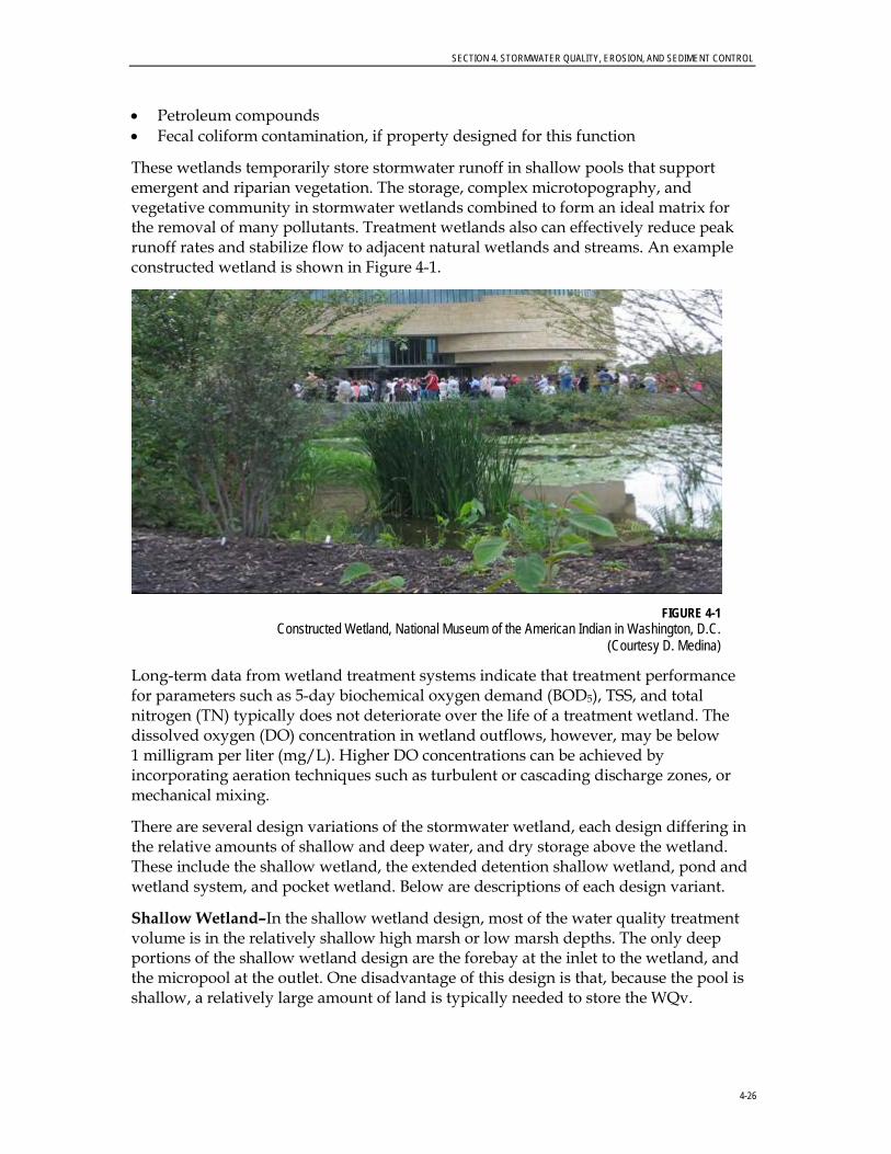
These wetlands temporarily store stormwater runoff in shallow pools that support emergent and riparian vegetation. The storage, complex microtopography, and vegetative community in stormwater wetlands combined to form an ideal matrix for the removal of many pollutants. Treatment wetlands also can effectively reduce peak runoff rates and stabilize flow to adjacent natural wetlands and streams. An example constructed wetland is shown in Figure 4-1.
FIGURE 4-1
Constructed Wetland, National Museum of the American Indian in Washington, D.C. (Courtesy D. Medina)
Long-term data from wetland treatment systems indicate that treatment performance for parameters such as 5-day biochemical oxygen demand (BOD5), TSS, and total nitrogen (TN) typically does not deteriorate over the life of a treatment wetland. The dissolved oxygen (DO) concentration in wetland outflows, however, may be below 1 milligram per liter (mg/L). Higher DO concentrations can be achieved by incorporating aeration techniques such as turbulent or cascading discharge zones, or mechanical mixing.
There are several design variations of the stormwater wetland, each design differing in the relative amounts of shallow and deep water, and dry storage above the wetland. These include the shallow wetland, the extended detention shallow wetland, pond and wetland system, and pocket wetland. Below are descriptions of each design variant.
Shallow Wetland–In the shallow wetland design, most of the water quality treatment volume is in the relatively shallow high marsh or low marsh depths. The only deep portions of the shallow wetland design are the forebay at the inlet to the wetland, and the micropool at the outlet. One disadvantage of this design is that, because the pool is shallow, a relatively large amount of land is typically needed to store the WQv.
SECTION 4. STORMWATER QUALITY, EROSION, AND SEDIMENT CONTROL
4-27
Extended Detention Shallow Wetland–The extended detention (ED) shallow wetland design is the same as the shallow wetland; however, part of the water quality treatment volume is provided as ED above the surface of the marsh and released over a period of 24 hours. This design can treat a greater volume of stormwater in a smaller space than can the shallow wetland design. In the ED wetland option, plants that can tolerate both wet and dry periods need to be specified in the ED zone.
Pond/Wetland Systems–The pond/wetland system has two separate cells–a wet pond and a shallow marsh. The wet pond traps sediments and reduces runoff velocities prior to entry into the wetland, where stormwater flows receive additional treatment. Less land is required for a pond/wetland system than for the shallow wetland or the ED shallow wetland systems.
Pocket Wetland–A pocket wetland is intended for smaller drainage areas of 5 to 10 acres and typically requires excavation down to the water table for a reliable water source to support the wetland system.
4.4.2.2 Application and Site Feasibility Criteria Stormwater wetlands generally are applicable to most types of new development and redevelopment, and can be used in both residential and nonresidential areas. Because of the large land requirements, however, wetlands may not be practical in higher-density areas. The following criteria should be evaluated to ensure the suitability of a stormwater wetland for meeting stormwater management objectives on a site or development.
4.4.2.3 General Design Considerations The criteria discussed below should be considered when designing stormwater wetlands.
General Feasibility. • Suitable for Residential Subdivision Usage–YES.
• Suitable for High Density/Ultra Urban Areas–Land requirements may preclude use.
• Regional Stormwater Control–YES.
Physical Feasibility–Physical Constraints at Project Site. • Drainage Area–A minimum of 25 acres and a positive water balance is needed to
maintain wetland conditions; 5 acres are needed for pocket wetlands.
• Space Required–Approximately 3 to 5 percent of the contributing drainage area.
• Site Slope–There should be no more than an 8-percent slope across the wetland site.
• Minimum Head–Elevation difference needed at a site from the inflow to the outflow: 3 to 5 feet; 2 to 3 feet for pocket wetland.
SECTION 4. STORMWATER QUALITY, EROSION, AND SEDIMENT CONTROL
4-28
• Minimum Depth to Water Table–If used on a site with an underlying water supply aquifer or when treating a hot spot, a separation distance of 2 feet is recommended between the bottom of the wetland and the elevation of the seasonally high water table; a pocket wetland is typically below the water table.
• Soils–Permeable soils are not well suited for a constructed stormwater wetland without a high water table. Underlying soils of hydrologic group “C” or “D” should be adequate to maintain wetland conditions. Most group “A” soils and some group “B” soils will require a liner. Evaluation of soils should be based on an actual subsurface analysis and permeability tests.
Other Constraints/Considerations. • A continuous base flow or high water table is required to support wetland
vegetation. A water balance must be performed to demonstrate that a stormwater wetland can withstand a 30-day drought at summer evaporation rates without completely drawing down.
• Wetland siting also should take into account the location and use of other site features such as natural depressions, buffers, and undisturbed natural areas, and should attempt to aesthetically “fit” the facility into the landscape. Bedrock close to the surface may prevent excavation.
• Stormwater wetlands cannot be located within navigable waters of the United States, including wetlands, without obtaining a Section 404 permit under the Clean Water Act (CWA), and any other applicable state permit. In some isolated cases, a wetlands permit may be granted to convert an existing degraded wetland in the context of local watershed restoration efforts.
• If a wetland facility is not used for overbank flood protection, it should be designed as an offline system to bypass higher flows rather than passing them through the wetland system.
• Minimum setback requirements for stormwater wetland facilities are as follows:
− From a property line 10 feet
− From a private well–100 feet; if well is downgradient from a hot spot land use, then the minimum setback is 250 feet
− From a septic system tank or leach field–50 feet
• All utilities should be located outside the wetland site.
4.4.2.4 Advantages • Creates a shallow matrix of sediment, plants, water, and detritus that collectively
removes multiple pollutants through a series of complementary physical, chemical, and biological processes.
• Provides good conditions for particle settling, sediment trapping, and reducing suspended solids transport.

SECTION 4. STORMWATER QUALITY, EROSION, AND SEDIMENT CONTROL
4-29
• Features relatively high efficiency in removing phosphorus, trace metals, and hydrocarbons that are adsorbed to the surfaces of suspended particles.
• Can provide attenuation of peak flood flows.
• Aesthetically pleasing when properly landscaped and maintained.
• Can provide an excellent habitat for wildlife and waterfowl.
• Relatively low maintenance when properly constructed and operated.
4.4.2.5 Disadvantages • Occupies more land than other stormwater BMPs.
• When sited in watersheds that are too small to provide adequate hydration, wetlands tend to dry out frequently and to function ineffectively. This problem generally can be avoided by properly sizing the wetland to match the available drainage area.
• Can be colonized by invasive species that out-compete native wetlands plants. Removal of invasive plants is difficult and labor intensive and may need to be done repeatedly. The chance of occurrence of this problem may be reduced by proper selection of the wetlands vegetation to be planted initially.
• If there are industrial or commercial land uses in the drainage area, accumulated pollutants may eventually increase environmental risks to wildlife. Typical pollutant loads found in urban settings are unlikely to cause this problem.
• If improperly designed, they may adversely affect existing wetland and forest areas in the region of the stormwater wetland by intercepting water that might otherwise reach the natural system.
• Can lead to overpopulation by waterfowl and thus increase the potential for bacterial contamination.
4.4.2.6 Design Procedures Step 1. Compute runoff control volumes
Calculate the WQv using the City’s stormwater quality site development review tool.
Step 2. Determine if the development site and conditions are appropriate for the use of a stormwater wetland
Refer to the site selection criteria listed in Section 4.6 of this Manual.
Step 3. Determine pretreatment volume
A sediment forebay should be is provided at each inlet, unless the inlet provides less than 10 percent of the total design storm inflow to the pond. The forebay should be sized to contain 0.1 inch per impervious acre of contributing drainage and should be 4 to 6 feet deep. The forebay storage volume counts toward the total WQv requirement and may be subtracted from the WQv for subsequent calculations.
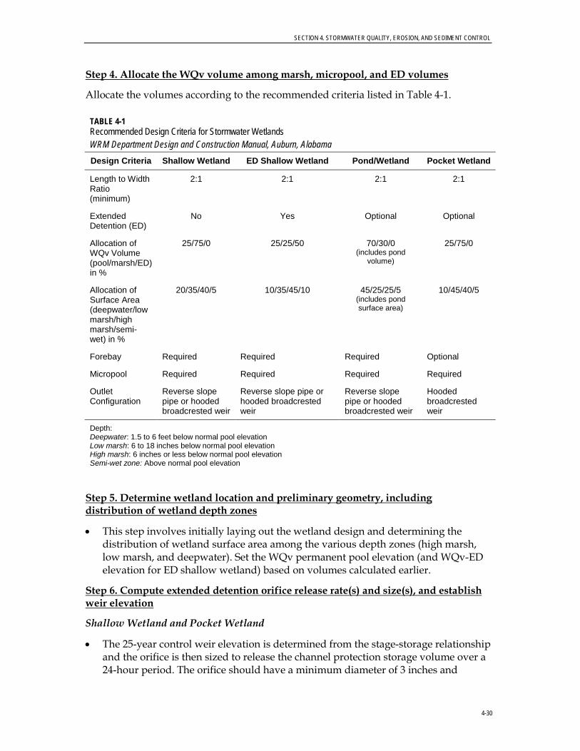
SECTION 4. STORMWATER QUALITY, EROSION, AND SEDIMENT CONTROL
4-30
Step 4. Allocate the WQv volume among marsh, micropool, and ED volumes
Allocate the volumes according to the recommended criteria listed in Table 4-1.
TABLE 4-1 Recommended Design Criteria for Stormwater Wetlands WRM Department Design and Construction Manual, Auburn, Alabama
Design Criteria Shallow Wetland ED Shallow Wetland Pond/Wetland Pocket Wetland
Length to Width Ratio (minimum)
2:1 2:1 2:1 2:1
Extended Detention (ED)
No Yes Optional Optional
Allocation of WQv Volume (pool/marsh/ED) in %
25/75/0 25/25/50 70/30/0 (includes pond
volume)
25/75/0
Allocation of Surface Area (deepwater/low marsh/high marsh/semi-wet) in %
20/35/40/5 10/35/45/10 45/25/25/5 (includes pond surface area)
10/45/40/5
Forebay Required Required Required Optional
Micropool Required Required Required Required
Outlet Configuration
Reverse slope pipe or hooded broadcrested weir
Reverse slope pipe or hooded broadcrested weir
Reverse slope pipe or hooded broadcrested weir
Hooded broadcrested weir
Depth: Deepwater: 1.5 to 6 feet below normal pool elevation Low marsh: 6 to 18 inches below normal pool elevation High marsh: 6 inches or less below normal pool elevation Semi-wet zone: Above normal pool elevation
Step 5. Determine wetland location and preliminary geometry, including distribution of wetland depth zones
• This step involves initially laying out the wetland design and determining the distribution of wetland surface area among the various depth zones (high marsh, low marsh, and deepwater). Set the WQv permanent pool elevation (and WQv-ED elevation for ED shallow wetland) based on volumes calculated earlier.
Step 6. Compute extended detention orifice release rate(s) and size(s), and establish weir elevation
Shallow Wetland and Pocket Wetland
• The 25-year control weir elevation is determined from the stage-storage relationship and the orifice is then sized to release the channel protection storage volume over a 24-hour period. The orifice should have a minimum diameter of 3 inches and
SECTION 4. STORMWATER QUALITY, EROSION, AND SEDIMENT CONTROL
4-31
should be adequately protected from clogging by an acceptable external trash rack. A reverse slope pipe attached to the riser, with its inlet submerged 1 foot below the elevation of the permanent pool, is a recommended design. The orifice diameter may be reduced to 1 inch if internal orifice protection is used (an over-perforated vertical stand pipe with ½-inch orifices or slots that are protected by wirecloth and a stone filtering jacket). Adjustable gate valves also can be used to achieve this equivalent diameter.
ED Shallow Wetland
• On the basis of the elevations established in Step 6 for the ED portion of the WQv, the water quality orifice is sized to release this extended detention volume in 24 hours. The water quality orifice should have a minimum diameter of 3 inches and should be adequately protected from clogging by an acceptable external trash rack. A reverse slope pipe attached to the riser, with its inlet submerged one foot below the elevation of the permanent pool, is a recommended design. Adjustable gate valves also can be used to achieve this equivalent diameter. The 25-year weir elevation is then determined from the stage-storage relationship. The invert of the channel protection orifice is located at the water quality ED elevation, and the orifice is sized to release the channel protection storage volume over a 24-hour period.
Step 7. Calculate Qp25 (25-year storm) release rate and water surface elevation
• Set up a stage-storage-discharge relationship for the control structure for the extended detention orifice(s) and the 25-year storm.
Step 8. Design embankment(s) and spillway(s)
• Size emergency spillway, calculate 100-year water surface elevation, set top of embankment elevation, and analyze safe passage of the extreme flood volume. At final design, provide safe passage for the 100-year event. Attenuation may not be required.
Step 9. Design inlets, sediment forebay(s), outlet structures, maintenance access, and safety features
Sediment Forebay and Inlets
• Sediment regulation is critical to sustain stormwater wetlands. A wetland facility should have a sediment forebay or equivalent upstream pretreatment. A sediment forebay is designed to remove incoming sediment from the stormwater flow prior to dispersal into the wetland. The forebay should consist of a separate cell, formed by an acceptable barrier. A forebay is to be provided at each inlet, unless the inlet provides less than 10 percent of the total design storm inflow to the wetland facility.
• The forebay is sized to contain 0.1 inch per impervious acre of contributing drainage and should be 4 to 6 feet deep. The pretreatment storage volume is part of the total WQv requirement and may be subtracted from WQv for wetland storage sizing.
SECTION 4. STORMWATER QUALITY, EROSION, AND SEDIMENT CONTROL
4-32
• A fixed vertical sediment depth marker shall be installed in the forebay to measure sediment deposition over time. The bottom of the forebay may be hardened (using concrete, paver blocks, etc.) to make sediment removal easier.
• Inflow channels are to be stabilized with flared rip-rap aprons, or the equivalent. Inlet pipes to the pond can be partially submerged. Exit velocities from the forebay must be non-erosive.
Outlet Structures
• Flow control from a stormwater wetland typically is accomplished with the use of a concrete or corrugated metal riser and barrel. The riser is a vertical pipe or inlet structure that is attached to the base of the micropool with a watertight connection. The outlet barrel is a horizontal pipe attached to the riser that conveys flow under the embankment. The riser should be located within the embankment for reasons of maintenance access, safety, and aesthetics.
• A number of outlets at varying depths in the riser provide internal flow control for routing of the water quality, channel protection, and overbank flood protection runoff volumes. The number of orifices can vary and is usually a function of the pond design.
• For shallow and pocket wetlands, the riser configuration is typically comprised of a channel protection outlet (usually an orifice) and overbank flood protection outlet (often a slot or weir).
• The channel protection orifice is sized to release the channel protection storage volume over a 24-hour period (12-hour ED may be warranted in some cold water streams). Because the WQv is fully contained in the permanent pool, no orifice sizing is necessary for this volume. As runoff from a water quality event enters the wet pond, it simply displaces that same volume through the channel protection orifice. Thus, an offline shallow or pocket wetland providing only water quality treatment can use a simple overflow weir as the outlet structure.
• In the case of an ED shallow wetland, there is generally a need for an additional outlet (usually an orifice) that is sized to pass the extended detention WQv that is surcharged on top of the permanent pool. Flow will first pass through this orifice, which is sized to release the water quality ED volume in 24 hours. The preferred design is a reverse slope pipe attached to the riser, with its inlet submerged 1 foot below the elevation of the permanent pool to prevent floatables from clogging the pipe and to avoid discharging warmer water at the surface of the pond. The next outlet is sized for the release of the channel protection storage volume. The outlet (often an orifice) invert is located at the maximum elevation associated with the extended detention WQv and is sized to release the channel protection storage volume over a 24-hour period (12-hour ED may be warranted in some cold water streams).
• Alternative hydraulic control methods to an orifice can be used and include a broad-crested rectangular, V-notch, proportional weir, or an outlet pipe protected by a hood that extends at least 12 inches below the normal pool.
SECTION 4. STORMWATER QUALITY, EROSION, AND SEDIMENT CONTROL
4-33
Maintenance Access (Recommended)
• A maintenance ROW or easement is recommended to access the wetland facility from a public or private road. The maintenance access should be at least 12 feet wide, have a maximum slope of no more than 15 percent, and be appropriately stabilized to withstand maintenance equipment and vehicles.
• The maintenance access should extend to the forebay, safety bench, riser, and outlet and, to the extent feasible, be designed to allow vehicles to turn around.
• Access to the riser is to be provided by lockable manhole covers and manhole steps within easy reach of valves and other controls.
Safety Features
• Fencing of wetlands generally is not desirable, but may be required by the City. A preferred method is to manage the contours of deep pool areas through the inclusion of a safety bench (see above) to eliminate dropoffs and reduce the potential for accidental drowning.
• The principal spillway opening should not permit access by small children, and end walls above pipe outfalls greater than 48 inches in diameter should be fenced to prevent a hazard.
Step 10. Prepare Vegetation and Landscaping Plan
• A landscaping plan should be provided that indicates the methods used to establish and maintain wetland coverage. Minimum elements of a plan include delineation of landscaping zones, selection of corresponding plant species, planting plan, sequence for preparing wetland bed (including soil amendments, if needed), and sources of plant material.
• Landscaping zones include low marsh, high marsh, and semi-wet zones. The low marsh zone ranges from 6 to 18 inches below the normal pool. This zone is suitable for the growth of several emergent plant species. The high marsh zone ranges from 6 inches below the pool up to the normal pool. This zone will support greater density and diversity of emergent wetland plant species. The high marsh zone should have a higher surface-area-to-volume ratio than does the low marsh zone. The semi-wet zone refers to those areas above the permanent pool that are inundated on an irregular basis and can be expected to support wetland plants.
• The landscaping plan should provide elements that promote greater wildlife and waterfowl use within the wetland and buffers.
• Woody vegetation may not be planted on the embankment or allowed to grow within 15 feet of the toe of the embankment or 25 feet from the principal spillway structure.
• A wetland buffer shall extend 25 feet outward from the maximum water surface elevation, with an additional 15-foot setback to structures. The wetland buffer should be contiguous with other buffer areas that are required by existing regulations (stream buffers) or that are part of the overall stormwater management

SECTION 4. STORMWATER QUALITY, EROSION, AND SEDIMENT CONTROL
4-34
concept plan. No structures should be located within the buffer, and an additional setback to permanent structures may be provided.
• Existing trees should be preserved in the buffer area during construction. It is desirable to locate forest conservation areas adjacent to ponds. To discourage resident geese populations, the buffer can be planted with trees, shrubs, and native ground covers.
• The soils of a wetland buffer are often severely compacted during the construction process to ensure stability. The density of these compacted soils is so great that it effectively prevents root penetration, and therefore, may lead to premature mortality or loss of vigor. Consequently, it is advisable to excavate large and deep holes around the proposed planting sites and to backfill these with uncompacted topsoil.
4.4.2.7 Design Example A shallow wetland design example is provided in the Maryland Stormwater Design Manual (2000), which can be obtained at the following internet link: http://www.mde.state.md.us/assets/document/appendixc1.pdf. It is important that the engineer performs all design calculations using local rainfall data and site-specific data (curve number [CN], soils, etc). The Maryland example is only a reference guide and numbers will vary depending on the site conditions. Technical Release 55 (TR-55) is recommended to calculate runoff volume. Figure 4-2 shows a plan view and profile of a typical shallow wetland. The sizing and shaping will vary based on the site topography and the runoff volume.
4.4.2.8 Monitoring and Maintenance Although wetlands generally are designed to require limited maintenance, they should be monitored to ensure the highest performance. The following monitoring activities are recommended:
• Assess plant cover periodically.
• Inspect wetlands annually after a rain event and after all large (mean annual or greater) events to ensure that the basin is operating as designed.
• Perform general inspections to identify localized problems such as changes in water level, erosion, sediment accumulation, or damage to flow control structures.
Maintenance is required, primarily to repair problems identified during the monitoring. Unlike maintenance requirements for wet or dry stormwater ponds, sediment should only selectively be removed from constructed treatment wetlands. Sediment removal disturbs stable vegetation cover and disrupts flow paths through the wetland. The wetland should be designed to accommodate moderate sediment levels, so that only sediments near the inlet and outlet should be removed.

SECTION 4. STORMWATER QUALITY, EROSION, AND SEDIMENT CONTROL
4-35
Note: Channel Protection Volume (CPv) shown in Figure 4-2 is not used in Auburn. The weir invert elevation at the CPv elevation should be set to meet the City’s discharge criteria, as detailed in the City of Auburn Stormwater Management Manual.
FIGURE 4-2 Schematic of Shallow Wetland
Source: Georgia Stormwater Management Manual (GSMM, 2001)
Pocket wetlands, or any wetland that has no sediment pretreatment, tend to accumulate sediment rapidly, and therefore, should be cleaned out when they accumulate 6 inches of deposition−in most cases, every 5 to 10 years.
Debris should be removed from pocket wetlands, or any treatment wetland, whenever it accumulates or at least twice annually.
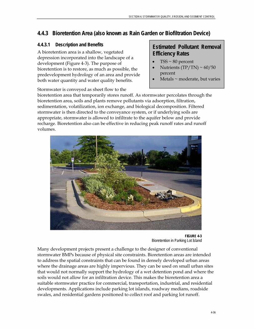
SECTION 4. STORMWATER QUALITY, EROSION, AND SEDIMENT CONTROL
4-36
4.4.3 Bioretention Area (also known as Rain Garden or Biofiltration Device)
4.4.3.1 Description and Benefits A bioretention area is a shallow, vegetated depression incorporated into the landscape of a development (Figure 4-3). The purpose of bioretention is to restore, as much as possible, the predevelopment hydrology of an area and provide both water quantity and water quality benefits.
Stormwater is conveyed as sheet flow to the bioretention area that temporarily stores runoff. As stormwater percolates through the bioretention area, soils and plants remove pollutants via adsorption, filtration, sedimentation, volatilization, ion exchange, and biological decomposition. Filtered stormwater is then directed to the conveyance system, or if underlying soils are appropriate, stormwater is allowed to infiltrate to the aquifer below and provide recharge. Bioretention also can be effective in reducing peak runoff rates and runoff volumes.
FIGURE 4-3
Bioretention in Parking Lot Island
Many development projects present a challenge to the designer of conventional stormwater BMPs because of physical site constraints. Bioretention areas are intended to address the spatial constraints that can be found in densely developed urban areas where the drainage areas are highly impervious. They can be used on small urban sites that would not normally support the hydrology of a wet detention pond and where the soils would not allow for an infiltration device. This makes the bioretention area a suitable stormwater practice for commercial, transportation, industrial, and residential developments. Applications include parking lot islands, roadway medians, roadside swales, and residential gardens positioned to collect roof and parking lot runoff.
Estimated Pollutant Removal Efficiency Rates • TSS ~ 80 percent • Nutrients (TP/TN) ~ 60/50
percent • Metals ~ moderate, but varies

SECTION 4. STORMWATER QUALITY, EROSION, AND SEDIMENT CONTROL
4-37
Bioretention areas are particularly effective on sites of 1 acre or less. A bioretention area is not suitable for regional-scale stormwater management.
Bioretention facilities are ideally deployed in an offline configuration (having the ability to bypass flow once the inflow begins to exceed the device capacity) to which the initial stormwater flows are diverted. An overflow control allows excess flows to bypass the facility. The offline setup can reduce potential erosion that may arise in an inline configuration. Bioretention facilities need an underdrain system when the native soil has a low infiltration rate. The underdrain system connects to another BMP or to the conveyance system. A grassed buffer strip aids in distributing the inflow and pretreats runoff by removing some of the suspended solids, which is recommended. Alternatively, a small forebay or a grass swale can serve as pretreatment.
4.4.3.2 General Design Considerations Figure 4-4 illustrates various bioretention area applications. The criteria described in the following text should be considered when designing bioretention areas.
General Feasibility. • Suitable for Residential Subdivision Usage–YES • Suitable for High Density/Ultra Urban Areas–YES • Regional Stormwater Control–NO
Physical Feasibility–Physical Constraints at Project Site. • Drainage Area–5 acres maximum; 0.5 to 2 acres are preferred
• Space Required–Approximately 5 percent of the contributing impervious area is required; minimum 200-ft2 area for small sites (10 feet x 20 feet)
• Site Slope–No more than 6-percent slope
• Minimum Head–Elevation difference needed at a site from the inflow to the outflow: 5 feet
• Minimum Depth to Water Table–A separation distance of 2 feet is recommended between the bottom of the bioretention facility and the elevation of the seasonally high water table
• Soils–No restrictions; engineered media required

SECTION 4. STORMWATER QUALITY, EROSION, AND SEDIMENT CONTROL
4-38
FIGURE 4-4
Bioretention Applications Source: GSMM (2001)
SECTION 4. STORMWATER QUALITY, EROSION, AND SEDIMENT CONTROL
4-39
Other Constraints/Considerations. • Native vegetation is preferred in bioretention areas. Plants should be tolerant of
both extreme wet and dry conditions. Publications, such as the Residential Rain Garden Handbook (Alabama Cooperative Extension System), provide a list of adapted species used in the region. The Alabama Cooperative Extension System specialists who are trained in bioretention technology also can provide plant selection guidance.
• Aquifer Protection–Do not allow exfiltration of filtered hot spot runoff into groundwater.
• Bioretention systems are designed for intermittent flow and must be allowed to drain and reaerate between rainfall events. They should not be used on sites with a continuous flow from groundwater, sump pumps, or other sources.
• Bioretention area locations should be integrated into the site planning process, and aesthetic considerations should be taken into account in their siting and design. Elevations must be carefully worked out to ensure that the desired runoff flow enters the facility with no more than the maximum design depth.
4.4.3.3 Advantages • Efficient removal method for suspended solids, heavy metals, and adsorbed
pollutants. Moderate to high removal of phosphorus, provided that the soil medium has a low phosphorus content. Certain configurations allow for moderate-high removal of nitrogen.
• Effective means of reducing peak runoff rates for relatively frequent storms, reducing runoff volumes, and recharging groundwater by infiltrating runoff.
• Flexible adaptation to urban retrofits.
• Successful use in small areas and, as distributed control measures, in large drainage areas or as part of low-impact development (LID).
• Natural integration into landscaping for habitat enhancement.
4.4.3.4 Disadvantages • In residential applications, homeowners need training to maintain the plant
material and mulch layer, and to provide general cleaning.
• Depending on the design, they may not be effective at removing nitrate.
• Surface soil layer may clog over time (although it can be restored easily).
• Frequent trash removal may be required, especially in high-traffic areas.
• Vigilance in protecting the bioretention area during construction is essential.

SECTION 4. STORMWATER QUALITY, EROSION, AND SEDIMENT CONTROL
4-40
4.4.3.5 Design Procedures Step 1. Compute runoff control volumes
• Calculate the WQv for the drainage area using the City’s Site Development Review Tool.
• Calculate the 100-year discharge to the bioretention area.
Step 2. Determine if the development site and conditions are appropriate for the use of a bioretention area
• Refer to the site selection criteria listed in Section 4.6 of this Manual.
Step 3. Size flow diversion structure, if needed
• A flow regulator (or flow splitter diversion structure) should be supplied to divert the WQv to the bioretention area.
Step 4. Determine size of bioretention ponding/filter area
• The required planting soil filter bed area is computed using the following equation (based on Darcy’s Law):
Af = (WQv) (df) / [ (k) (hf + df) (tf)]
where: Af = surface area of ponding area (ft2)
WQv = water quality volume (or total volume to be captured) df = filter bed depth (4-foot minimum) k = coefficient of permeability of filter media (ft/day) (use 0.5 foot/day for silt-loam) hf = average height of water above filter bed (feet) (typically 3 inches, which is half of the 6-inch ponding depth) tf = design filter bed drain time (days) (2 days or 48 hours is recommended maximum)
Step 5. Set design elevations and dimensions of facility
• Recommended minimum dimensions of a bioretention area are 10 feet wide by 20 feet long. All designs except small residential applications should maintain a length-to-width ratio of at least 2:1.
• The planting soil filter bed is sized using a Darcy’s Law equation with a filter bed drain time of 48 hours and a coefficient of permeability (k) of 0.5 feet per day (ft/day).
• The maximum recommended ponding depth of the bioretention areas is 6 inches.
• The planting soil bed must be at least 4 feet deep. Planting soils should be sandy loam, loamy sand, or loam texture with a clay content ranging from 10 to 25 percent. The soil must have an infiltration rate of at least 0.5 inch per hour and a pH between 5.5 and 6.5. In addition, the planting soil should have a 1.5- to 3-percent organic content and a maximum 500 parts per million (ppm) concentration of soluble salts.
• For online configurations, a grass filter strip with a pea gravel diaphragm typically is used as the pretreatment measure. The required length of the filter strip depends
SECTION 4. STORMWATER QUALITY, EROSION, AND SEDIMENT CONTROL
4-41
on the drainage area, imperviousness, and the filter strip slope. Design guidance regarding the filter strips for pretreatment is included in Section 4.4.10 of this Manual.
• For offline applications, a grass channel with a pea gravel diaphragm flow spreader is used for pretreatment. The length of the grass channel depends on the drainage area, land use, and channel slope. The minimum grassed channel length should be 20 feet. Design guidance regarding the grass channels for pretreatment is provided in Section 4.4.5 of this Manual.
• The mulch layer should consist of 2 to 4 inches of commercially available, fine-shredded hardwood mulch or shredded hardwood chips.
• The sand bed should be 12 to 18 inches thick. Sand should be clean and have less than 15-percent silt or clay content.
• Pea gravel for the diaphragm and curtain, where used, should be ASTM D 448 size No. 6 (1/8-inch to 1/4-inch).
Step 6. Design pretreatment
• Pretreat with a grass filter strip (online configuration) or grass channel (offline), and stone diaphragm.
Step 7. Size underdrain system
• The underdrain collection system is equipped with a 6-inch perforated PVC pipe (American Association of State Highway and Transportation Officials [AASHTO] M 252) in an 8-inch gravel layer. The pipe should have 3/8-inch perforations, spaced at 6-inch centers, with a minimum of 4 holes per row. The pipe is spaced at a maximum of 10 feet on center and a minimum grade of 0.5 percent must be maintained. A permeable filter fabric is placed between the gravel layer and the planting soil bed.
Step 8. Design emergency overflow
• An overflow must be provided to bypass and/or convey larger flows to the downstream drainage system or stabilized watercourse. Non-erosive velocities need to be ensured at the outlet point.
Step 9. Prepare Vegetation and Landscaping Plan
• A landscaping plan for the bioretention area should be prepared to indicate how it will be established with vegetation.
4.4.3.6 Design Example The following example focuses on the design of a bioretention facility to meet the water quality treatment requirements of the site. Channel protection and overbank flood control are not addressed in this example other than through the quantification of preliminary storage volume and peak discharge requirements. In general, the primary function of bioretention is to provide water quality treatment, rather than large storm attenuation. As such, flows in excess of the WQv typically are routed to bypass the
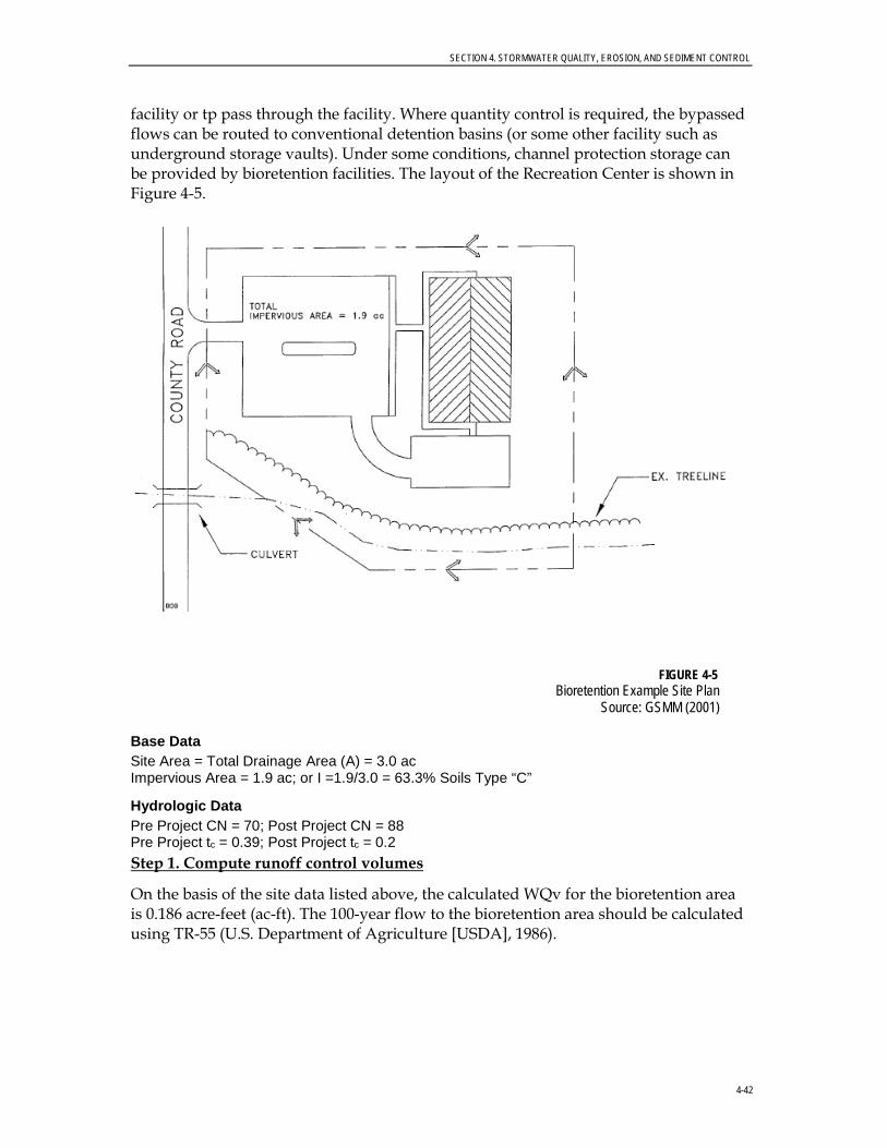
SECTION 4. STORMWATER QUALITY, EROSION, AND SEDIMENT CONTROL
4-42
facility or tp pass through the facility. Where quantity control is required, the bypassed flows can be routed to conventional detention basins (or some other facility such as underground storage vaults). Under some conditions, channel protection storage can be provided by bioretention facilities. The layout of the Recreation Center is shown in Figure 4-5.
FIGURE 4-5 Bioretention Example Site Plan
Source: GSMM (2001)
Base Data Site Area = Total Drainage Area (A) = 3.0 ac Impervious Area = 1.9 ac; or I =1.9/3.0 = 63.3% Soils Type “C”
Hydrologic Data Pre Project CN = 70; Post Project CN = 88 Pre Project tc = 0.39; Post Project tc = 0.2 Step 1. Compute runoff control volumes
On the basis of the site data listed above, the calculated WQv for the bioretention area is 0.186 acre-feet (ac-ft). The 100-year flow to the bioretention area should be calculated using TR-55 (U.S. Department of Agriculture [USDA], 1986).
SECTION 4. STORMWATER QUALITY, EROSION, AND SEDIMENT CONTROL
4-43
Step 2. Determine if the development site and conditions are appropriate for the use of a bioretention area
Site-specific Data:
The existing ground elevation at the facility location is 922 feet, mean sea level. Soil boring observations reveal that the seasonally high water table is at 913 feet and the underlying soil is silt loam (ML). The adjacent creek invert is at 912 feet.
Step 3. Size flow diversion structure, if needed
Bioretention areas can be either on or offline. Online facilities generally are sized to receive, but not necessarily treat, the 25-year event. Offline facilities are designed to receive a more or less exact flow rate through a weir, channel, manhole, “flow splitter,” etc. This facility is situated to receive direct runoff from grass areas and parking lot curb openings and piping for the 25-year event (19 cubic feet per minute [cfs]), and no special flow diversion structure is incorporated.
Step 4. Determine size of bioretention ponding / filter area Af = (WQv) (df) / [ (k) (hf + df) (tf)]
Af = (8,102 ft3)(5’) / [(0.5’/day) (0.25’ + 5’) (2 days)] (With k = 0.5'/day, hf = 0.25’, tf = 2 days) = 7,716 ft2
Step 5. Set design elevations and dimensions of facility
Assume a roughly 2-to-1 rectangular shape. Given a filter area requirement of 7,716 ft2, say the facility is roughly 65 feet by 120 feet (Figure 4-6). Set the top of facility at 921 feet, with the berm at 922 feet. The facility is 5 feet deep, which will allow 3 feet of freeboard over the seasonally high water table. Figure 4-7 shows a typical section of the facility.
Step 6. Design pretreatment
Pretreat with a grass channel, based on the guidance provided in Section 4.4.10 of this Manual. For a 3-acre drainage area, 63-percent imperviousness, and a slope less than 2 percent, provide a 90-foot grass channel at a 1.5-percent slope. The value from Table 4-2 is 30 feet for a 1-acre drainage area.
Step 7. Size underdrain system
Base the underdrain design on 10 percent of the surface area of the filter bed (Af) or 772 ft2. Using 6-inch perforated plastic pipes surrounded by a 3-foot-wide gravel bed, 10 feet on center (Figures 5-6 and 5-7). Thus, (772 ft2)/3 feet per foot of underdrain = 257 feet, for 260 feet of perforated underdrain.
To ensure against the planting media getting clogged, design a small ornamental stone window of 20-inch to 5-inch stone connected directly to the sand filter layer. This area is based on 5 percent of the Af, or 386 ft2, say 14 feet by 28 feet (Figures 5-6 and 5-7).

SECTION 4. STORMWATER QUALITY, EROSION, AND SEDIMENT CONTROL
4-44
FIGURE 4-6 Bioretention Facility Layout
Source: GSMM (2001)
FIGURE 4-7 Bioretention Facility Typical Section
Source: GSMM (2001)
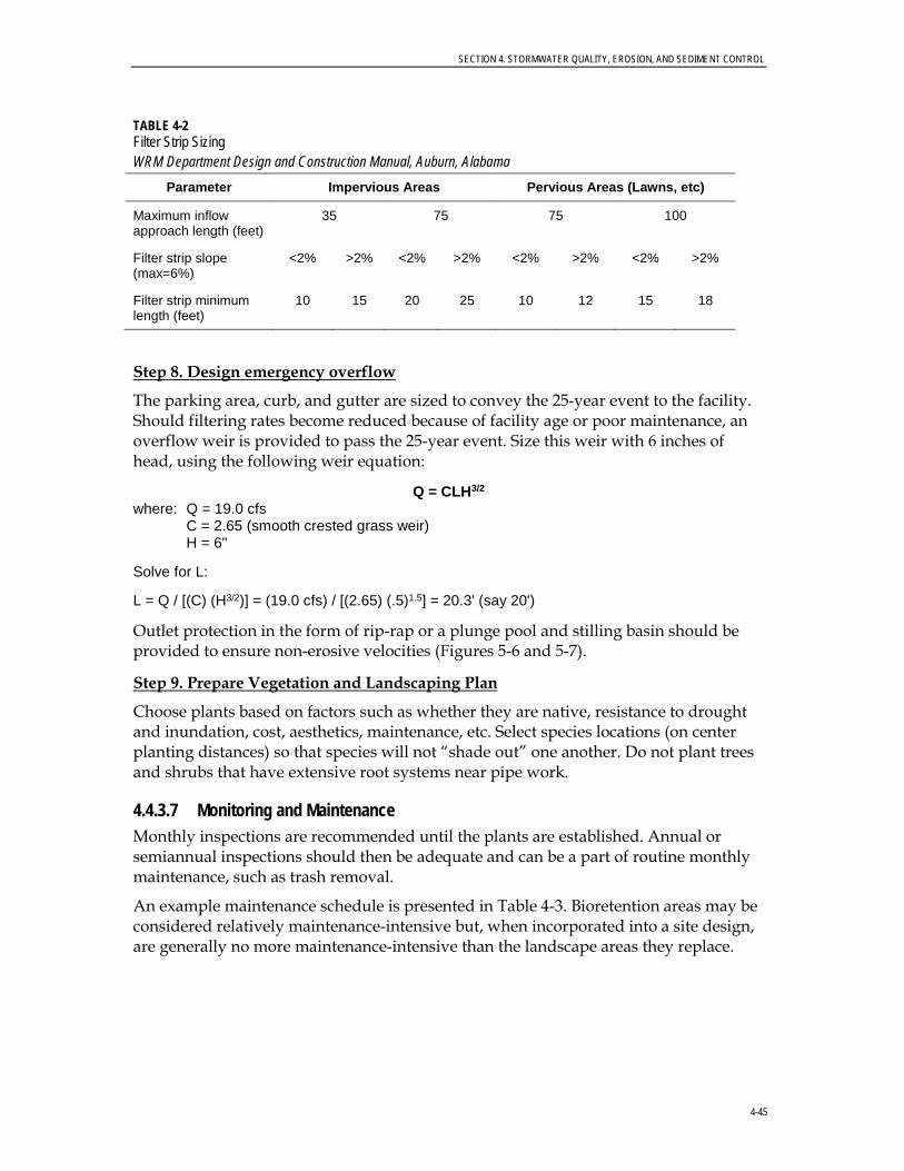
SECTION 4. STORMWATER QUALITY, EROSION, AND SEDIMENT CONTROL
4-45
TABLE 4-2 Filter Strip Sizing WRM Department Design and Construction Manual, Auburn, Alabama
Parameter Impervious Areas Pervious Areas (Lawns, etc)
Maximum inflow approach length (feet)
35 75 75 100
Filter strip slope (max=6%)
<2% >2% <2% >2% <2% >2% <2% >2%
Filter strip minimum length (feet)
10 15 20 25 10 12 15 18
Step 8. Design emergency overflow
The parking area, curb, and gutter are sized to convey the 25-year event to the facility. Should filtering rates become reduced because of facility age or poor maintenance, an overflow weir is provided to pass the 25-year event. Size this weir with 6 inches of head, using the following weir equation:
Q = CLH3/2 where: Q = 19.0 cfs C = 2.65 (smooth crested grass weir) H = 6"
Solve for L:
L = Q / [(C) (H3/2)] = (19.0 cfs) / [(2.65) (.5)1.5] = 20.3' (say 20')
Outlet protection in the form of rip-rap or a plunge pool and stilling basin should be provided to ensure non-erosive velocities (Figures 5-6 and 5-7).
Step 9. Prepare Vegetation and Landscaping Plan
Choose plants based on factors such as whether they are native, resistance to drought and inundation, cost, aesthetics, maintenance, etc. Select species locations (on center planting distances) so that species will not “shade out” one another. Do not plant trees and shrubs that have extensive root systems near pipe work.
4.4.3.7 Monitoring and Maintenance Monthly inspections are recommended until the plants are established. Annual or semiannual inspections should then be adequate and can be a part of routine monthly maintenance, such as trash removal.
An example maintenance schedule is presented in Table 4-3. Bioretention areas may be considered relatively maintenance-intensive but, when incorporated into a site design, are generally no more maintenance-intensive than the landscape areas they replace.

SECTION 4. STORMWATER QUALITY, EROSION, AND SEDIMENT CONTROL
4-46
TABLE 4-3 Example Maintenance Schedule for Bioretention Areas WRM Department Design and Construction Manual, Auburn, Alabama
Description Method Frequency Time of Year
Soil
Inspect and repair erosion; clean up trash; flush underdrain pipes Visual Monthly Monthly
Organic Layer
Remulch any void areas By hand Whenever needed Whenever needed Remove previous mulch layer before applying new layer (optional) By hand Once every 2 times
mulch is added Spring
Add any additional mulch if necessary By hand Twice a year Spring/Fall
Plants
Remove and replace all dead and diseased vegetation considered beyond treatment
Mechanical or by hand Twice a year
March 15 to April 30 and October 1 to
November 30
Treat all diseased trees and shrubs Mechanical or by hand Not applicable
Varies, but will depend on insect or disease infestation
Water plant material at the end of each day for 14 consecutive days and after planting has been completed
By hand Once a year Remove stakes only in the spring
Replace support stakes By hand Once a year Whenever needed Replace any deficient stakes or wires By hand Whenever needed Whenever needed
Remove mulch from outlets and cleanouts By hand Monthly or as needed Monthly
4.4.3.8 Soil Media When the filtering capacity diminishes substantially (when water ponds on the surface for more than 24 hours), the top few inches of material must be removed and replaced with fresh material. The removed sediments should be disposed in an acceptable manner (landfill).
4.4.4 Wet Detention Basin (also known as Stormwater Retention or Detention Ponds)
4.4.4.1 Description and Benefits A wet detention basin is a stormwater management facility that includes a permanent pool of water for removing pollutants and additional capacity above the permanent pool for detaining stormwater runoff (for peak flow attenuation). Wet detention basins can often be made part of a multi-use recreation facility that provides additional benefits for the community above and beyond stormwater management.
Estimated Pollutant Removal Efficiency Rates • TSS ~ 80 percent • Nutrients (TP/TN) ~ 50/
30 percent • Metals ~ 50 percent (cadmium,
copper, lead, and zinc) • Pathogens ~ 70 percent

SECTION 4. STORMWATER QUALITY, EROSION, AND SEDIMENT CONTROL
4-47
In wet detention basins, a permanent pool of standing water is maintained by the riser–the elevated outlet of the wet detention basin (Figure 4-8). Water in the permanent pool mixes with and dilutes the initial runoff from storm events. Wet detention basins fill with stormwater and release most of the mixed flow over a period of a few days, slowly returning the basin to its normal depth. Wet detention basins do the following:
• Improve water quality by two mechanisms; first, by settling of suspended particulates (sediments and attached pollutants) to remove the following pollutants:
− Sediment − Organic matter − Metals
Second, by dilution during the storm and biological uptake (consumption of pollutants by plants) after the storm to remove dissolved pollutants, including the following:
• Nutrients • Dissolved metals
FIGURE 4-8 Permanent Pool of Water in Wet Detention Basin
SECTION 4. STORMWATER QUALITY, EROSION, AND SEDIMENT CONTROL
4-48
Extending the detention time of stormwater runoff can be an effective means of: 1) controlling stream bank erosion by reducing the magnitude and frequency of erosive runoff events downstream; and 2) improving water quality by allowing particulate pollutants to settle.
Runoff generated during the early phases of a storm usually has the highest concentrations of sediment and dissolved pollutants. Because a wet detention basin dilutes and settles pollutants in the initial runoff, the concentration of pollutants in runoff released to downstream drainages is reduced. The total mass of pollutants released to downstream areas also can be substantially reduced by using wet detention basins. If the basin is not adequately maintained (such as by periodic dredging), storm flows may resuspend sediments and deliver them to the stream.
Generally, there are two types of basins, excavated or embankment. Excavated basins are normally the simplest to construct and maintain. Embankment basins deal with more complex issues such as earthen dams and possible destruction of property if these structures fail.
Therefore, all embankment ponds must be designed and certified by a PE before construction.
Except as otherwise provided by the subdivision regulations or the City Code, the detention pond provisions of this Manual do not apply to development properties smaller than 1 acre.
4.4.4.2 General Design Considerations The following criteria should be considered when designing wet detention basins.
General Feasibility. • Suitable for Residential Subdivision Usage–YES
• Suitable for High Density/Ultra-Urban Areas–Land requirements may preclude use
• Regional Stormwater Control–YES
Physical Feasibility – Physical Constraints at Project Site. • Drainage Area–A minimum of 25 acres is needed for a wet pond and a wet ED
pond to maintain a permanent pool; 10 acres minimum is needed for a micropool ED pond. A smaller drainage area may be acceptable with an adequate water balance and anti-clogging device.
• Space Required–Approximately 2 to 3 percent of the contributing drainage area.
• Site Slope–There should be more than 15-percent slope across the pond site. However, the pond should not be constructed on eroding or unstable slopes.
• Minimum Head–Elevation difference needed at a site from the inflow to the outflow: 6 to 8 inches

SECTION 4. STORMWATER QUALITY, EROSION, AND SEDIMENT CONTROL
4-49
• Minimum Depth to Water Table–If used on a site with an underlying water supply aquifer or when treating a hot spot, a separation distance of 2 feet is required between the bottom of the pond and the elevation of the seasonally high water table.
• Soils–Underlying soils of hydrologic Group “C” or “D” should be adequate to maintain a permanent pool. Most Group “A” soils and some group “B” soils will require a pond liner. The evaluation of soils should be based on an actual subsurface analysis and permeability tests.
Other Constraints/Considerations. • A stormwater pond should be sited such that the topography allows for maximum
runoff storage at minimum excavation or construction costs. Pond siting also should take into account the location and use of other site features such as buffers and undisturbed natural areas and should attempt to aesthetically “fit” the facility into the landscape. Bedrock close to the surface may prevent excavation.
• Stormwater ponds cannot be located within a stream or any other navigable waters of the United States, including wetlands, without obtaining a USACE Section 404 permit under the CWA, and any other applicable state permit.
• Minimum setback requirements for stormwater pond facilities are as follows:
− From a property line–10 feet
− From a private well–100 feet; if well is downgradient from a hot spot land use, then the minimum setback is 250 feet
− From a septic system tank or leach field–50 feet
• All utilities should be located outside the pond or basin site.
• According to the City’s Stormwater Management Manual requirements, permanently wet basins must contain side slopes that are no steeper than 3H:1V out to a depth of 2 feet below the normal water level. If steeper side slopes are required because of space constraints, the basin can be fenced or otherwise restricted from public access.
4.4.4.3 Advantages • Can be aesthetically pleasing and can be sited in both low- and high-visibility areas.
• Often perceived by residents as enhancing property values, as well as the aesthetic appeal of the area.
• Can provide wildlife habitat and a focal point for recreation.
• Best technique available for reducing the frequency of flooding events that cause bank erosion.

SECTION 4. STORMWATER QUALITY, EROSION, AND SEDIMENT CONTROL
4-50
• Appropriate in areas where infiltration is impractical because of low infiltration rates of the underlying soils.
• Can reduce the peak runoff rate from a developed site and control downstream erosion.
4.4.4.4 Disadvantages • Sometimes create problems such as nuisance odors, algae blooms, and rotting
debris when not properly maintained; dying plants may need to be harvested or removed periodically to prevent plant nutrients from being released back into the water.
• If not properly maintained, wet detention basins can become eyesores.
• May pose drowning hazards and other public safety issues.
• Unless inlets are maintained often, trash accumulation can occur.
• Although some waterfowl are desirable, larger concentrations of these animals could be a nuisance and contribute large concentrations of bacteria (fecal coliform) to the downstream waterbody.
• May contribute to thermal pollution and cause downstream warming, so may not be appropriate in areas where sensitive aquatic species live; outlets that “pull” water below the normal pool elevation can be helpful in controlling thermal pollution.
4.4.4.5 Design Procedures Step 1. Compute runoff control volumes
• Calculate the WQv for the drainage area using the City’s Site Development Review Tool.
• Consult the City’s Stormwater Management Manual for criteria relating to controlling the 2-, 5-, 10-, and 25-year, 24-hour storm events.
• Consult Section 4.2 of the City’s Stormwater Management Manual for general design procedures.
Step 2. Determine if the development site and conditions are appropriate for the use of a stormwater pond
• Refer to the site selection criteria listed in Section 4.6 of this Manual.
Step 3. Determine pretreatment volume
• A sediment forebay is provided at each inlet, unless the inlet provides less than 10 percent of the total design storm inflow to the pond. The forebay should be sized to contain 0.1 inch per impervious acre of contributing drainage and should be 4 to 6 feet deep. The forebay storage volume counts toward the total WQv requirement and may be subtracted from the WQv for subsequent calculations.
SECTION 4. STORMWATER QUALITY, EROSION, AND SEDIMENT CONTROL
4-51
Step 4. Determine permanent pool volume (and water quality ED volume) • Size the permanent pool volume to 1 x WQv.
Step 5. Determine pond location and preliminary geometry • Refer to Section 4 of the City’s Stormwater Management Manual for pond design
guidelines.
Step 6. Compute extended detention orifice release rate(s) and size(s) • Include an orifice in the control structure sized to release the channel protection
storage volume over a 24-hour period. The orifice should have a minimum diameter of 3 inches and should be protected adequately from clogging by an acceptable external trash rack. A reverse slope pipe attached to the riser, with its inlet submerged 1 foot below the elevation of the permanent pool, is a recommended design. The orifice diameter may be reduced to 1 inch if internal orifice protection is used (an over-perforated vertical stand pipe with ½-inch orifices or slots that are protected by wirecloth and a stone filtering jacket). Adjustable gate valves also can be used to achieve this equivalent diameter.
Step 7. Design inlets, sediment forebay(s), outlet structures, maintenance access, and safety features • Design outlet structures according to Section 4.2.5 of the City’s Stormwater
Management Manual. Include the extended detention orifice, as detailed in Step 7.
• Design sediment according to Section 4.2.6 of the City’s Stormwater Management Manual.
• Design inlets according to Section 4.2.7 of the City’s Stormwater Management Manual.
• A maintenance ROW or easement must be provided to a pond from a public or private road. Maintenance access should be at least 12 feet wide, have a maximum slope of no more than 15 percent, and be stabilized appropriately to withstand maintenance equipment and vehicles.
• The maintenance access must extend to the forebay, safety bench, riser, and outlet and, to the extent feasible, be designed to allow vehicles to turn around.
• Access to the riser is to be provided by lockable manhole covers, and manhole steps within easy reach of valves and other controls.
Step 8. Prepare Vegetation and Landscaping Plan • A landscaping plan for a stormwater pond and its buffer should be prepared to
indicate how aquatic and terrestrial areas will be stabilized and established with vegetation.

SECTION 4. STORMWATER QUALITY, EROSION, AND SEDIMENT CONTROL
4-52
4.4.4.6 Design Example A design example for a wet detention basin is provided in Section 4.3 of the City’s Stormwater Management Manual. Note that this example does not include any provision for WQv and would require some modifications to be used as a water quality BMP. The designer would need to calculate the required WQv using the City’s Site Development Review Tool (there is not enough information in the example to include a value here). The WQv is contained between the invert of an orifice set at the permanent pool elevation and a weir designed to meet the maximum peak discharge criteria established by the City’s Stormwater Management Manual. The orifice would be sized to release the WQv over a 24-hour period based on the average head on the orifice (the average of the elevation at the center of the orifice and the elevation of the crest of the overflow weir). The elevations listed in the example and the dimensions of the pond probably would have to be modified to accommodate the additional WQv. The sizing of the overflow weir is detailed in the City’s Stormwater Management Manual.
4.4.4.7 Monitoring and Maintenance Detailed inspections by a qualified inspector to ascertain the operational condition and safety of the facility, particularly the condition of embankments, outlet structures, and other safety-related features, should occur at least annually to verify that the facility is operating as designed and to identify any maintenance requirements. If possible, inspections should occur during wet weather to verify that the facility is maintaining desirable retention times. In addition to regularly scheduled inspections, deficiencies should be noted during any visits by City or other maintenance personnel. At a minimum, inspections should address the following:
• Examination of plantings
• Settling, woody growth, animal burrowing, and signs of piping in the embankment
• Signs of seepage on the downstream face of the embankment
• Condition of wet detention basin floor, perimeter of the wet detention basin, and grass cover on the embankment
• Excessive erosion or sedimentation in or around the basin
• Rip-rap displacement or failure
• If principal and emergency spillways meet the design plans for operation
• Outlet controls, inlet controls, debris racks, and mechanical and electrical equipment
• Inlet and outlet channel conditions
• Stability of slopes
• Safety features of the facility
• Access for maintenance equipment

SECTION 4. STORMWATER QUALITY, EROSION, AND SEDIMENT CONTROL
4-53
• Signs of trespass or unauthorized traffic
• Sediment buildup
Additionally, a program of regular monitoring of the aquatic environment for a permanent wet detention basin should be established to allow for the timely correction of any imbalance in the ecosystem; such monitoring can prevent more serious problems from occurring.
The maintenance requirements for wet detention basins are intensive compared to most BMPs. Normal maintenance costs can range from 3 to 5 percent of the construction costs annually (Schueler, 1992). Areas of concern include excessive weed growth, maintaining adequate vegetative cover, sedimentation, bank erosion, insect control, outlet stoppages, algal growth, embankment failures, and seepage.
4.4.5 Grassed Swale (also known as Enhanced Swale or Biofiltration Swale) 4.4.5.1 Description and Benefits A grassed swale is a shallow open-channel drainageway stabilized with grass or other herbaceous vegetation and designed to convey runoff and to filter pollutants.
Grassed swales typically are used in residential and commercial developments, as well as along highway medians, as alternatives or enhancements to conventional storm sewers (Figure 4-9). Swales remove pollutants from stormwater by filtration through grasses and other vegetation, settling, and infiltration through soil. Swales work best in conjunction with other BMPs. Grassed swales are designed with limited longitudinal slopes to force the flow to be slow and shallow, thus allowing for particulates to settle and limiting the effects of erosion. Grassed swales occasionally are enhanced with check dams to retain water and promote infiltration. Swales rely on vegetation to perform biofiltration functions (Gwinnett County, 1999).
FIGURE 4-9
Recently Constructed Grassed Swale in Residential Area, Pembroke Woods Subdivision in Emmittsburg, MD (Courtesy of Mike Clar, Ecosite, Inc., Columbia, MD)
Estimated Pollutant Removal Efficiency Rates • TSS ~ 80 percent • Nutrients (TP/TN) ~ 50/
50 percent • Metals ~ 40 percent
SECTION 4. STORMWATER QUALITY, EROSION, AND SEDIMENT CONTROL
4-54
Care should be taken to design grassed swales with the length, slope, and vegetation type needed to provide effective stormwater attenuation and filtration. For grassed swales, pollutant removal depends on the design, but properly designed grassed swales can be efficient in managing the following:
• Peak flows • Channel protection • Pretreatment before bioretention or other BMPs • Suspended solids • Nitrate • Oxygen-demanding substances • Metals (including copper, lead, and zinc) • TP
Swales are not to be confused with filter strip or grass channels, which are limited application structural controls and not considered acceptable for meeting the TSS removal performance goal by themselves. Ordinary grass channels are not engineered to provide the same treatment capability as a well-designed biofiltration swale. Filter strips are designed to accommodate overland flow rather than channelized flow and can be used as stormwater credits to help reduce the total water quality treatment volume for a site. Both of these practices may be used for pretreatment or be included in a “treatment train” approach where redundant treatment is provided.
4.4.5.2 General Design Considerations The following criteria should be considered when designing grassed swales.
General Feasibility. • Suitable for Residential Subdivision Usage–YES • Suitable for High Density/Ultra Urban Areas–NO • Regional Stormwater Control–NO
Physical Feasibility–Physical Constraints at Project Site. • Drainage Area–5 acres maximum.
• Space Required–Approximately 10 to 20 percent of the contributing impervious area.
• Site Slope–Typically no more than 4-percent channel slope.
• Minimum Head–Elevation difference needed at a site from the inflow to the outflow: 3 to 5 feet.
• Minimum Depth to Water Table–2 feet required between the bottom of the swale and the elevation of the seasonally high water table, if an aquifer or hot spot is present.
• Depth of Ponding–store WQv with less than 18 inches of ponding at the downstream end.
• Bottom Width–Bottom width should range from 2 to 8 feet
SECTION 4. STORMWATER QUALITY, EROSION, AND SEDIMENT CONTROL
4-55
• Side slopes–No greater than 2:1 (4:1 recommended)
• Soils–No restrictions
Other Constraints/Considerations. • Aquifer Protection–Exfiltration should not be allowed for hot spots. • The swale should be sited such that the topography allows for the design of a
channel with sufficiently mild slope (unless small drop structures are used) and cross-sectional area to maintain non-erosive velocities.
4.4.5.3 Advantages • Can reduce runoff peak rates and increase opportunities for filtration, partially
infiltrating runoff from small storm events if the underlying soil is not compacted or saturated. Underdrains can be installed to compensate for low hydraulic conductivities in the native soil.
• Can reduce the use of costly development infrastructure (curb and gutter).
• Can be aesthetically pleasing.
• Low-slope swales can create wetland areas.
• Unmowed systems not adjacent to roadways can provide valuable “wet meadow” habitat.
4.4.5.4 Disadvantages • Could be subject to standing water and mosquito infestations.
• May be subject to channelization due to concentrated flows.
• Steep roadside swales may pose traffic hazards in residential subdivisions. Shallow swales should not present an excessive traffic hazard. Accepted state and federal references should be required when establishing the safety protocol.
4.4.5.5 Design Procedures Step 1. Compute runoff control volumes
• Calculate the WQv for the drainage area using the City’s Site Development Review Tool.
Step 2. Determine if the development site and conditions are appropriate for the use of an enhanced swale system
• Refer to the site selection criteria listed in Section 4.6 of this Manual.
Step 3. Determine swale dimensions
• Consider the application and site feasibility criteria listed in Section 4.4.5.2 of this Manual.
SECTION 4. STORMWATER QUALITY, EROSION, AND SEDIMENT CONTROL
4-56
Step 4. Compute number of check dams (or similar structures) required to detain WQv
• Use 18-inch maximum ponding depth requirement to calculate the required number of check dams.
Step 5. Calculate draw-down time.
• Planting soil should pass a maximum rate of 1.5 feet in 24 hours and must completely filter WQv within 48 hours.
Step 6. Check 2-year and 25-year velocity erosion potential and freeboard
• Check for erosive velocities and modify design as appropriate. Provide 6 inches of freeboard.
Step 7. Design low flow orifice at downstream headwalls and checkdams
• Design orifice to pass WQv in 6 hours. Use Orifice equation.
Step 8. Design inlets, sediment forebay(s), and underdrain system
Inlets
• Inlets to enhanced swales must be provided with energy dissipators such as rip-rap.
Pre-treatment
• Pretreatment of runoff in a swale system typically is provided by a sediment forebay located at the inlet. The pretreatment volume should be equal to 0.1 inch per impervious acre. This storage is usually obtained by providing check dams at pipe inlets and/or driveway crossings.
• Enhanced swale systems that receive direct concentrated runoff may have a 6-inch drop to a pea gravel diaphragm flow spreader at the upstream end of the control.
• A pea gravel diaphragm and gentle side slopes should be provided along the top of channels to provide pretreatment for lateral sheet flows.
Underdrain
• The bed of the swale consists of a permeable soil layer of at least 30 inches deep, above a 4-inch-diameter perforated PVC pipe (AASHTO M 252) longitudinal underdrain in a 6-inch gravel layer. The soil media should have an infiltration rate of at least 1 foot per day (1.5 feet per day maximum) and contain a high level of organic material to facilitate pollutant removal. A permeable filter fabric is placed between the gravel layer and the overlying soil.
Step 9. Prepare Vegetation and Landscaping Plan • A landscaping plan for a swale should be prepared to indicate how the enhanced
swale system will be stabilized and established with vegetation.
SECTION 4. STORMWATER QUALITY, EROSION, AND SEDIMENT CONTROL
4-57
4.4.5.6 Design Example Basic Data: Small commercial lot 300 feet deep x 145 feet wide located in Auburn Drainage area (A) = 1 acre Impervious percentage (I) = 70%
Step 1. Compute runoff control volumes
The calculated WQv for the drainage area using the City’s Site Development Review Tool is 0.068 ac-ft.
Calculate the flow to the swale for the water quality storm event (P=1.2 inches) using TR-55. For this example, the flow is peak discharge (Qwq) = 1.22 cfs.
Step 2. Determine if the development site and conditions are appropriate for the use of an enhanced swale system
For this example, it is assumed that use of an enhanced swale system is appropriate.
Step 3. Determine swale dimensions
The maximum flow depth for water quality treatment should be approximately the same height of the grass. A maximum flow depth of 4 inches is allowed for water quality design. A maximum flow velocity of 1 fps for water quality treatment is required. For Manning’s n, use 0.15 for medium grass, 0.25 for dense grass, and 0.35 for dense Bermuda-type grass. The site slope is 2 percent.
Input variables: n= 0.15 S = 0.02 ft/ft D = 4/12 = 0.33 ft
Using the equation:
Qwq = Q = VA = (1.49/n) * (D2/3 S1/2 DW)
where: Q = peak flow (cfs) V = velocity (ft/sec) A = flow area (ft2) = WD W = channel bottom width (ft) D = flow depth (ft) S = slope (ft/ft)
(Note: D approximates hydraulic radius for shallow flows.) W = (nQ)/(1.49 * D5/3 * S1/2)
= (0.15*1.22)/(1.49*0.335/3* 0.021/2) = 5.5 feet minimum
V = Q/(WD) = 1.22/(4.0 5.5 * 4/12) = 0.92 0.67 fps (okay)
(Note: WD approximates the flow area for shallow flows.)
Minimum length for 5-minute residence time:
L = V * (5*60) = 201 feet
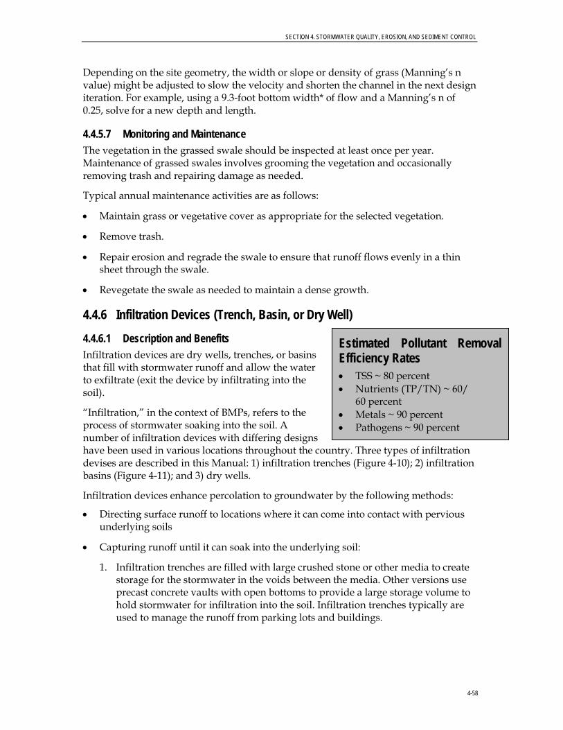
SECTION 4. STORMWATER QUALITY, EROSION, AND SEDIMENT CONTROL
4-58
Depending on the site geometry, the width or slope or density of grass (Manning’s n value) might be adjusted to slow the velocity and shorten the channel in the next design iteration. For example, using a 9.3-foot bottom width* of flow and a Manning’s n of 0.25, solve for a new depth and length.
4.4.5.7 Monitoring and Maintenance The vegetation in the grassed swale should be inspected at least once per year. Maintenance of grassed swales involves grooming the vegetation and occasionally removing trash and repairing damage as needed.
Typical annual maintenance activities are as follows:
• Maintain grass or vegetative cover as appropriate for the selected vegetation.
• Remove trash.
• Repair erosion and regrade the swale to ensure that runoff flows evenly in a thin sheet through the swale.
• Revegetate the swale as needed to maintain a dense growth.
4.4.6 Infiltration Devices (Trench, Basin, or Dry Well)
4.4.6.1 Description and Benefits Infiltration devices are dry wells, trenches, or basins that fill with stormwater runoff and allow the water to exfiltrate (exit the device by infiltrating into the soil).
“Infiltration,” in the context of BMPs, refers to the process of stormwater soaking into the soil. A number of infiltration devices with differing designs have been used in various locations throughout the country. Three types of infiltration devises are described in this Manual: 1) infiltration trenches (Figure 4-10); 2) infiltration basins (Figure 4-11); and 3) dry wells.
Infiltration devices enhance percolation to groundwater by the following methods:
• Directing surface runoff to locations where it can come into contact with pervious underlying soils
• Capturing runoff until it can soak into the underlying soil:
1. Infiltration trenches are filled with large crushed stone or other media to create storage for the stormwater in the voids between the media. Other versions use precast concrete vaults with open bottoms to provide a large storage volume to hold stormwater for infiltration into the soil. Infiltration trenches typically are used to manage the runoff from parking lots and buildings.
Estimated Pollutant Removal Efficiency Rates • TSS ~ 80 percent • Nutrients (TP/TN) ~ 60/
60 percent • Metals ~ 90 percent • Pathogens ~ 90 percent

SECTION 4. STORMWATER QUALITY, EROSION, AND SEDIMENT CONTROL
4-59
FIGURE 4-10 Typical Infiltration Trench
Adapted from (1992); Source: GSMM (2001)
FIGURE 4-11 Typical Infiltration Basin with Sand Filter
Source: GSMM (2001)

SECTION 4. STORMWATER QUALITY, EROSION, AND SEDIMENT CONTROL
4-60
2. Infiltration basins are normally dry basins, much like ED detention basins, with the exception that the stormwater does not flow out into a receiving stream. Rather, the stormwater is allowed to infiltrate.
3. Dry wells are similar to infiltration trenches, but are sufficiently smaller to be considered as a separate BMP. Dry wells are most useful for receiving the runoff from roofs of buildings and allowing it to infiltrate into the soil.
Infiltration trenches generally are suited for medium- to high-density residential, commercial, and institutional developments where the subsoil is sufficiently permeable to provide a reasonable infiltration rate and the water table is low enough to prevent groundwater contamination. They are applicable primarily for impervious areas where there are not high levels of fine particulates (clay/silt soils) in the runoff and should only be considered for sites where the sediment load is relatively low.
All types of infiltration devices have the following benefits:
• Reduce runoff volume • Recharge groundwater • Provide high removal efficiencies for sediment • Provide high removal efficiencies for pollutants adsorbed onto sediment particles
To protect groundwater from potential contamination, runoff from designated hot spot land uses or activities must not be infiltrated. Infiltration trenches should not be used for manufacturing and industrial sites, where there is a potential for high concentrations of soluble pollutants and heavy metals. In addition, infiltration should not be considered for areas that have high pesticide concentrations. Infiltration trenches also are not suitable in areas that have karst geology without adequate geotechnical testing by qualified individuals and in accordance with local requirements.
4.4.6.2 General Design Considerations The following criteria should be considered when designing infiltration areas.
General Feasibility. • Suitable for Residential Subdivision Usage–YES • Suitable for High Density/Ultra Urban Areas–YES • Regional Stormwater Control–NO
Physical Feasibility–Physical Constraints at Project Site. • Drainage Area–5 acres maximum.
• Space Required–Will vary depending on the depth of the facility.
• Site Slope–No more than 6-percent slope (for preconstruction facility footprint).
• Minimum Head–Elevation difference needed at a site from the inflow to the outflow: 1 foot.
SECTION 4. STORMWATER QUALITY, EROSION, AND SEDIMENT CONTROL
4-61
• Minimum Depth to Water Table–4 feet recommended between the bottom of the infiltration trench and the elevation of the seasonally high water table.
• Soils–Infiltration rate greater than 0.5-inch-per-hour required (typically hydrologic Group “A”; some Group “B” soils).
Other Constraints/Considerations. • Aquifer Protection–No hot spot runoff allowed; must meet setback requirements in
the design criteria.
4.4.6.3 Advantages • Reduce frequency of flooding by increasing the amount of water entering the soil. • Help maintain shallow groundwater, which supports dry-weather flows in streams. • Have particulate pollutant removal efficiencies generally as good as other BMPs. • Are economical for small drainage areas (fewer than 10,000 ft2 of storage volume).
4.4.6.4 Disadvantages • Often fail relatively quickly compared to other types of BMPs. In many instances,
this premature failure is due to excess sediment from sites that have not been properly stabilized.
• Tend to clog easily, so pretreatment BMPs must be used to remove coarse particulate pollutants.
• Restricted to areas that have permeable soils, deep water tables, deep bedrock, and stable areas where stormwater contains little sediment or can be pretreated to reduce the sediment load.
• Require significant maintenance to enhance longevity and maintain performance.
• May cause undesirable groundwater seepage into basements and foundations if not properly sited.
• Infiltration of stormwater may contaminate groundwater (Schueler et al., 1992). This is an important concern, although Caltrans (2000) indicates that little pollution travels beyond 20 inches below the facility bottom.
4.4.6.5 Design Procedures Step 1. Compute runoff control volumes
• Calculate the WQv for the drainage area using the City’s Site Development Review Tool.
Step 2. Determine if the development site and conditions are appropriate for the use of an infiltration trench
• Refer to the site selection criteria listed in Section 4.6 of this Manual.
SECTION 4. STORMWATER QUALITY, EROSION, AND SEDIMENT CONTROL
4-62
Step 4. Size flow diversion structure, if needed
• A flow regulator (or flow splitter diversion structure) should be supplied to divert the WQv to the infiltration trench.
• Size low-flow orifice, weir, or other device to fully dewater the WQv in 24 to 48 hours after the rainfall event.
Step 6. Size infiltration trench
• The area of the trench can be determined from the following equation:
( )12/kTndWQ
A v
+=
where: A = Surface Area WQv = Water Quality Volume (or total volume to be infiltrated) n = porosity d = trench depth (feet) k = percolation (inches/hour) T= Fill Time (time for the practice to fill with water), in hours
• A porosity value n = 0.32 should be used.
• A fill time T=2 hours can be used for most designs.
• Trench depths should be between 3 and 8 feet, to provide for easier maintenance. The width of a trench must be less than 25 feet.
• Broader, shallow trenches reduce the risk of clogging by spreading the flow over a larger area for infiltration.
• The bottom slope of a trench should be flat across its length and width to evenly distribute flows, encourage uniform infiltration through the bottom, and reduce the risk of clogging.
• The stone aggregate used in the trench should be washed, bank-run gravel, 1.5 to 2.5 inches in diameter, with a void space of about 40 percent (ALDOT No. 3 Stone). Aggregate contaminated with soil shall not be used. A porosity value (void space/total volume) of 0.32 should be used in the calculations, unless aggregate-specific data exist.
• A 6-inch layer of clean, washed sand should be placed on the bottom of the trench to encourage drainage and prevent compaction of the native soil while the stone aggregate is added.
• The infiltration trench is lined on the sides and top by an appropriate geotextile filter fabric that prevents soil piping, but that has greater permeability than the parent soil. The top layer of filter fabric is located 2 to 6 inches from the top of the trench and serves to prevent sediment from passing into the stone aggregate. Because this top layer serves as a sediment barrier, it will need to be replaced more frequently and must be readily separated from the side sections.

SECTION 4. STORMWATER QUALITY, EROSION, AND SEDIMENT CONTROL
4-63
• The top surface of the infiltration trench above the filter fabric typically is covered with pea gravel. The pea gravel layer improves sediment filtering and maximizes the pollutant removal in the top of the trench. In addition, it can easily be removed and replaced should the device begin to clog. Alternatively, the trench can be covered with permeable topsoil and planted with grass in a landscaped area.
• An observation well must be installed in every infiltration trench and should consist of a perforated PVC pipe, 4 to 6 inches in diameter, extending to the bottom of the trench (Figure 4-7 provides a schematic of an observation well used in a bioretention facility). The observation well will show the rate of dewatering after a storm, as well as provide a means of determining sediment levels at the bottom and when the filter fabric at the top is clogged and maintenance is needed. It should be installed along the centerline of the structure, flush with the ground elevation of the trench.
• A visible floating marker should be provided to indicate the water level. The top of the well should be capped and locked to discourage vandalism and tampering.
• The trench excavation should be limited to the width and depth specified in the design.
• Excavated material should be placed away from the open trench so as not to jeopardize the stability of the trench sidewalls. The bottom of the excavated trench shall not be loaded in a way that causes soil compaction, and should be scarified prior to placement of sand. The sides of the trench shall be trimmed of all large roots. The sidewalls shall be uniform, with no voids, and shall be scarified prior to backfilling. All infiltration trench facilities should be protected during site construction and should be constructed after upstream areas have been stabilized.
Step 7. Determine pretreatment volume and design pretreatment measures
• Size the pretreatment facility to treat 25 percent of the WQv for offline configurations.
• Pretreatment facilities must always be used in conjunction with an infiltration trench to prevent clogging and failure.
• For a trench receiving sheet flow from an adjacent drainage area, the pretreatment system should consist of a vegetated filter strip with a minimum 25-foot length. A vegetated buffer strip around the entire trench is required if the facility is receiving runoff from both directions. If the infiltration rate for the underlying soils is greater than 2 inches per hour, 50 percent of the WQv should be pretreated by another method prior to reaching the infiltration trench.
• For an offline configuration, pretreatment should consist of a sediment forebay, vault, plunge pool, or similar sedimentation chamber (with energy dissipaters) sized to 25 percent of the WQv. Exit velocities from the pretreatment chamber must be non-erosive for the 2-year design storm.
SECTION 4. STORMWATER QUALITY, EROSION, AND SEDIMENT CONTROL
4-64
Step 8. Design spillway(s)
• Adequate stormwater outfalls should be provided for the overflow that exceeds the capacity of the trench, thus ensuring non-erosive velocities on the downslope.
4.4.6.6 Design Example The following example focuses on the design of an infiltration trench to meet the water quality treatment requirements of the site. Channel protection and overbank flood control are not addressed in this example other than quantification of preliminary storage volume and peak discharge requirements. In general, the primary function of infiltration trenches is to provide water quality treatment and groundwater recharge, but not large storm attenuation. As such, flows in excess of the WQv typically are routed to bypass the facility or pass through the facility. Where quantity control is required, the bypassed flows can be routed to conventional detention basins (or some other facility such as underground storage vaults). The layout of the Community Center is shown in Figure 4-12.
Base Data Site Area = Total Drainage Area (A) = 3.0 ac Impervious Area = 1.9 ac; or I =1.9/3.0 = 63.3% Soils Type “C”
Hydrologic Data Pre Project CN = 70; Post Project CN = 88 Pre Project tc = 0.39; Post Project tc = 0.2
Step 1. Compute runoff control volumes
The WQv for the infiltration trench would be calculated using the City’s Site Development Tool. The WQv was determined to be 0.186 ac-ft or 8,102 cubic feet (ft3). The 100-year flow and the 25-year, 24-hour event to size the infiltration trench were calculated using TR-55.
Step 2. Determine if the development site and conditions are appropriate for the use of a infiltration trench
Site-specific Data:
Existing ground elevation at the facility location is 922 feet, mean sea level. Soil boring observations reveal that the seasonally high water table is at 913 feet and the underlying soil is silt loam (ML). The adjacent creek invert is at 912 feet.
Assuming the above-mentioned conditions, it was assumed the infiltration trench is a suitable BMP for this application.
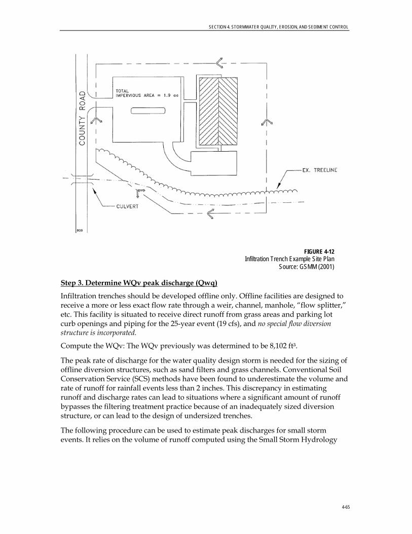
SECTION 4. STORMWATER QUALITY, EROSION, AND SEDIMENT CONTROL
4-65
FIGURE 4-12
Infiltration Trench Example Site Plan Source: GSMM (2001)
Step 3. Determine WQv peak discharge (Qwq)
Infiltration trenches should be developed offline only. Offline facilities are designed to receive a more or less exact flow rate through a weir, channel, manhole, “flow splitter,” etc. This facility is situated to receive direct runoff from grass areas and parking lot curb openings and piping for the 25-year event (19 cfs), and no special flow diversion structure is incorporated.
Compute the WQv: The WQv previously was determined to be 8,102 ft3.
The peak rate of discharge for the water quality design storm is needed for the sizing of offline diversion structures, such as sand filters and grass channels. Conventional Soil Conservation Service (SCS) methods have been found to underestimate the volume and rate of runoff for rainfall events less than 2 inches. This discrepancy in estimating runoff and discharge rates can lead to situations where a significant amount of runoff bypasses the filtering treatment practice because of an inadequately sized diversion structure, or can lead to the design of undersized trenches.
The following procedure can be used to estimate peak discharges for small storm events. It relies on the volume of runoff computed using the Small Storm Hydrology

SECTION 4. STORMWATER QUALITY, EROSION, AND SEDIMENT CONTROL
4-66
Method (Pitt, 1994) and uses the Natural Resource Conservation Service (NRCS), TR-55 Graphical Peak Discharge Method (USDA, 1986). A brief description of the calculation procedure is presented below:
CN = 1000 / [10 + 5P +10Q - 10(Q² + 1.25 QP)½] where: P = rainfall, in inches (use 1.2" for the Water Quality Storm) Q = runoff volume, in inches (equal to WQV ÷ area)
Once a CN is computed, the time of concentration (tc) is computed (based on the methods identified in TR-55).
Using the computed CN, tc, and drainage area (A), in acres, the Qwq for the water quality storm is computed (based on the procedures identified in TR-55). Use the appropriate rainfall distribution type.
Step 4. Determine size of infiltration trench Af = (WQv) / (nd + kT/12)
Af = (8,102 ft3) / (0.32 x 5’ + 1”/ hour x 2 hours / 12) (With n = 0.32, d = 5, k = 1”/hour, T = 2 hours) = 4,586 ft2
Because the width can be no greater than 25 feet (see above, feasibility), determine the length:
L = 4,586 ft2 / 25 ft L = 183 feet
Assume that one third of the runoff from the site drains to Point A and two thirds drains to Point B. Use an L-shaped trench in the corner of the site (Figure 4-13 provides a site plan view). The surface area of the trench is proportional to the amount of runoff it drains (the portion draining from Point A is half as large as the portion draining from Point B).
Step 5. Size the flow diversion structures
Because two entrances are used, two flow diversions are needed, as follows:
For the entire site:
Q25-year = 17 cfs Peak flow for WQv = 2.2 cfs. (Step 3).
For the first diversion (Point A):
Assume peak flow equals 1/3 of the value for the entire site. Thus, Q25-year = 17/3 = 5.7 cfs Peak flow for WQv = 2.2/3 = 0.73 cfs
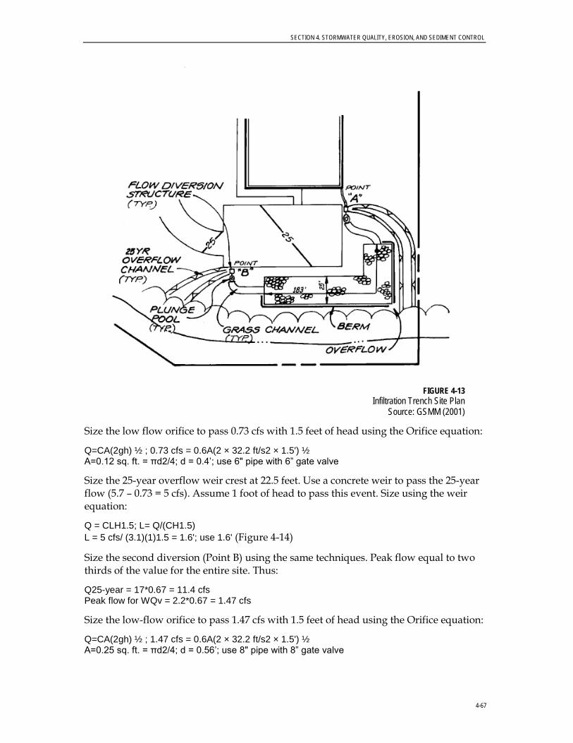
SECTION 4. STORMWATER QUALITY, EROSION, AND SEDIMENT CONTROL
4-67
FIGURE 4-13
Infiltration Trench Site Plan Source: GSMM (2001)
Size the low flow orifice to pass 0.73 cfs with 1.5 feet of head using the Orifice equation:
Q=CA(2gh) ½ ; 0.73 cfs = 0.6A(2 × 32.2 ft/s2 × 1.5') ½ A=0.12 sq. ft. = πd2/4; d = 0.4’; use 6" pipe with 6” gate valve
Size the 25-year overflow weir crest at 22.5 feet. Use a concrete weir to pass the 25-year flow (5.7 – 0.73 = 5 cfs). Assume 1 foot of head to pass this event. Size using the weir equation:
Q = CLH1.5; L= Q/(CH1.5) L = 5 cfs/ (3.1)(1)1.5 = 1.6'; use 1.6' (Figure 4-14)
Size the second diversion (Point B) using the same techniques. Peak flow equal to two thirds of the value for the entire site. Thus:
Q25-year = 17*0.67 = 11.4 cfs Peak flow for WQv = 2.2*0.67 = 1.47 cfs
Size the low-flow orifice to pass 1.47 cfs with 1.5 feet of head using the Orifice equation:
Q=CA(2gh) ½ ; 1.47 cfs = 0.6A(2 × 32.2 ft/s2 × 1.5') ½ A=0.25 sq. ft. = πd2/4; d = 0.56’; use 8" pipe with 8” gate valve
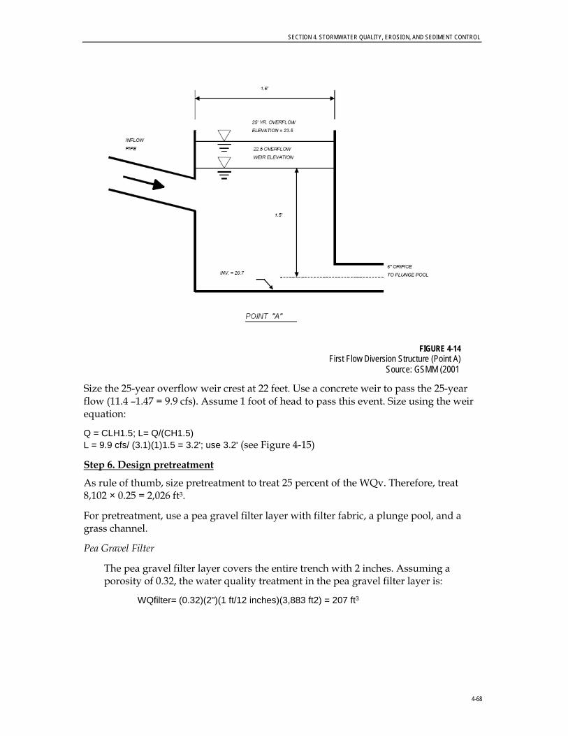
SECTION 4. STORMWATER QUALITY, EROSION, AND SEDIMENT CONTROL
4-68
FIGURE 4-14
First Flow Diversion Structure (Point A) Source: GSMM (2001
Size the 25-year overflow weir crest at 22 feet. Use a concrete weir to pass the 25-year flow (11.4 –1.47 = 9.9 cfs). Assume 1 foot of head to pass this event. Size using the weir equation:
Q = CLH1.5; L= Q/(CH1.5) L = 9.9 cfs/ (3.1)(1)1.5 = 3.2'; use 3.2' (see Figure 4-15)
Step 6. Design pretreatment
As rule of thumb, size pretreatment to treat 25 percent of the WQv. Therefore, treat 8,102 × 0.25 = 2,026 ft3.
For pretreatment, use a pea gravel filter layer with filter fabric, a plunge pool, and a grass channel.
Pea Gravel Filter
The pea gravel filter layer covers the entire trench with 2 inches. Assuming a porosity of 0.32, the water quality treatment in the pea gravel filter layer is:
WQfilter= (0.32)(2")(1 ft/12 inches)(3,883 ft2) = 207 ft3

SECTION 4. STORMWATER QUALITY, EROSION, AND SEDIMENT CONTROL
4-69
FIGURE 4-15
Second Flow Diversion Structure (Point B) Source: GSMM (2001
Plunge Pools
Use a 5-foot x 10-foot plunge pool at Point A and a 10-foot x 10-foot plunge pool at Point B with average depths of 2 feet:
Total WQpool= (10 ft)(10+5 ft)(2 ft) = 300 ft3
Grass Channel
Thus, the grass channel needs to treat at least (2,026 - 207 - 300) ft3 = 1,519 ft3
Use a Manning’s equation nomograph or software to size the swale.
The channel at Point A should treat one third of 1,519 ft3 or 501 ft3.
• Assume a trapezoidal channel with 4-foot channel bottom, 3H:1V side slopes, and a Manning’s n value of 0.15. Use a nomograph to size the swale; assume a 1-percent slope.
• Use a peak discharge of 0.73 cfs (Peak flow for one third of WQv, or 2,674 ft3)
• Compute velocity: V=0.5 fps
• To retain the 1/3 of the WQv (2,674 ft3) for 10 minutes, the length would be 300 feet.

SECTION 4. STORMWATER QUALITY, EROSION, AND SEDIMENT CONTROL
4-70
• Because the swale only needs to treat 25 percent of the WQv minus the treatment provided by the plunge pool and the gravel layer, or 501 ft3, the length should be pro-rated to reflect this reduction.
Therefore, adjust length as follows: L= (300 ft)(501 ft3/2,674 ft3) =56 feet. Use 60 feet.
The channel at Point B should treat two thirds of 1,519 ft3, or 1,018 ft3
• Assume a trapezoidal channel with 5-foot channel bottom, 3H:1V side slopes, and a Manning’s n value of 0.12. Use a nomograph to size the swale; assume a 0.5-percent slope.
• Use a peak discharge of 1.47 cfs (Peak flow for two thirds of WQv, or 5,428 ft3)
• Compute velocity: V=0.5 fps
• To retain the 2/3 of the WQv (5,428 ft3) for 10 minutes, the length would be 300 feet.
• Because the swale only needs to treat 25 percent of the WQv minus the treatment provided by the plunge pool and the gravel layer, or 1,018 ft3, the length should be prorated to reflect this reduction.
Therefore, adjust length as follows:
L= (300 ft)(1,018 ft3/5,428 ft3) = 56 feet. Use 60 feet.
Step 7. Design spillway
Adequate stormwater outfalls should be provided for the overflow associated with the 25-year and larger design storm events to ensure non-erosive velocities on the downslope.
Step 8. Design emergency overflow
The parking area, curb, and gutter are sized to convey the 25-year event to the facility. Should filtering rates become reduced because of facility age or poor maintenance, an overflow weir is provided to pass the 25-year event. Size this weir with 6 inches of head, using the weir equation:
Q = CLH3/2 where: Q = 19.0 cfs
C = 2.65 (smooth crested grass weir) H = 6"
Solve for L: L = Q / [(C) (H3/2)] or (19.0 cfs) / [(2.65) (.5)1.5] = 20.3' (say 20')
Step 9. Prepare Vegetation and Landscaping Plan
Choose plants based on factors such as whether they are native, resistance to drought and inundation, cost, aesthetics, maintenance, etc. Select species locations (on center planting distances) so that species will not “shade out” one another. Do not plant trees and shrubs that have extensive root systems near pipe work.
SECTION 4. STORMWATER QUALITY, EROSION, AND SEDIMENT CONTROL
4-71
4.4.6.7 Monitoring and Maintenance Sediment accumulation eventually will render an infiltration device ineffective, so regular inspections are necessary. Because the trenches and dry wells are belowground and out of sight, there can be a tendency is to ignore inspection and maintenance, which leads to failure. Regular inspections of all types of infiltration devices will help ensure that problems are identified in advance.
A monitoring well should be installed in all infiltration devices to facilitate proper monitoring. For the first year of operation, installations should be inspected quarterly and after each major storm. After the first year, annual inspections, preferably conducted after a storm, are recommended.
Property owners should be educated in the function and maintenance requirements of infiltration devices. Especially important is the maintenance of vegetated areas that drain to the infiltration system. Areas that are allowed to become bare and unvegetated will contribute excess sediment to the infiltration system and hasten its failure. Maintenance requirements are summarized as follows:
• Grass areas, grassed swales, and filter strips leading to infiltration devices should have a dense vegetation cover and be mowed at least twice a year.
• Sediment deposits should be removed from pretreatment devices at least annually.
• In trenches, the top several inches of aggregate and the filter cloth along the top of the trench or dry wells should be replaced annually or at least when the facility shows evidence that infiltration rates have declined. Proper disposal of the removed materials is necessary.
• The surfaces of infiltration trenches must be kept in good condition. Colonization by grass or other plants should be discouraged because it can lead to reduced surface infiltration rates. In many instances, it is convenient to cover infiltration trenches with concrete grid pavers or similar permeable paving systems that can be removed easily and replaced as necessary to service the trench.
• The infiltration facility must be dismantled and reconstructed when the infiltration rate drops to unacceptable levels.
4.4.7 Buffers (also known as Riparian Forested Buffers) 4.4.7.1 Description and Benefits Buffers are natural or constructed low-maintenance ecosystems adjacent to surface water bodies where trees, grasses, shrubs, and/or herbaceous plants function as a filter to remove pollutants from overland stormwater flow and shallow groundwater flow before discharge to receiving waters.
Effective buffers filter pollutants through natural mechanisms such as deposition, infiltration, adsorption, absorption, filtration, biodegradation, and
Estimated Pollutant Removal Efficiency Rates* • TSS ~ 85 percent • Nutrients (TP/TN) ~ 40/
30 percent • Metals ~ 50 percent • Pathogens ~ 70 percent *The pollutant removal effectiveness of vegetated buffers varies with the width of the buffer.

SECTION 4. STORMWATER QUALITY, EROSION, AND SEDIMENT CONTROL
4-72
plant uptake. Riparian buffers also improve habitat by providing food and cover for wildlife and aquatic organisms (Figure 4-16). Riparian buffers alone cannot provide all of the surface runoff treatment required (both water quality and quantity), but can help in the following ways:
• Attenuating the rate of runoff into streams • Increasing infiltration and recharge to groundwater and surface water bodies • Reducing erosion of streams and riverbanks • Improving aquatic habitat • Reducing sedimentation and pollutants • Reducing sediment-binding pollutants, including some metals and organics
FIGURE 4-16 Forested Buffer with Well-developed Streambank Vegetation
4.4.7.2 General Design Considerations The following criteria should be considered when selecting buffers.
General Feasibility. • Suitable for Residential Subdivision Usage–YES • Suitable for High Density/Ultra Urban Areas–YES • Regional Stormwater Control–NO
Physical Feasibility–Physical Constraints at Project Site. • Section 413 of the City’s Zoning Ordinance (May 2, 2006) requires buffers varying in
width from 35 feet to 100 feet perpendicular from each side of the stream bank, creek, or waterway under “bank-full conditions.” The buffer requirements apply to all perennial and intermittent streams as defined in Section 413.02 of the ordinance.
SECTION 4. STORMWATER QUALITY, EROSION, AND SEDIMENT CONTROL
4-73
Other Constraints/Considerations. • Generally, the wider the stream buffer, the more effectively pollutants are removed
from surface runoff. Consider a wider stream buffer (if possible) in areas where pollutant loading from the upstream watershed is expected to be high.
• If planting is needed in the buffer, the use or reinforcement of existing vegetation is preferred. However, where improvements are required, sodding, plugging, and the use of stockpiled vegetation or seeding are acceptable.
• No clearing or grading of land in the buffer zone may occur without the City’s written permission.
4.4.7.3 Advantages • Offers numerous aesthetic and passive recreational benefits.
• Provides water quality treatment, erosion control, and water temperature benefits.
• Maintaining trails that are constructed, marked, and signed well can build support for greenways of riparian forest in urban and suburban watersheds.
• Owners of commercial and institutional properties that front on urban water bodies can be encouraged to landscape the areas and add to riparian buffers.
• Inexpensive to "construct."
4.4.7.4 Disadvantages • Sometimes seen as dangerous or unkempt public areas.
• Shrubby bank-side vegetation can be perceived as interfering with views of streams.
• Can be abused as places for illegal dumping.
• By the time the riparian corridor is reached, surface flow frequently has become concentrated into swales or the buffer has been bypassed by underground storm drains discharging to the stream. Therefore, benefits may be limited to the area that is contributing sheet flow to the buffer itself.
4.4.7.5 Stream Buffers Purpose. The purpose of this subsection is to establish minimal acceptable requirements for the design of buffers to ensure that the stream and adjacent land will fulfill their natural functions; to reduce land development impacts on stream water quality and flows; and to provide for the environmentally sound use of the City’s land resources.

SECTION 4. STORMWATER QUALITY, EROSION, AND SEDIMENT CONTROL
4-74
Definitions. For the purpose of this section, these words and phrases shall be defined as specified below:
A. Perennial stream: A natural watercourse which contains flowing water, year around.
B. Intermittent stream: One which flows only at certain times of the year when it receives water from springs or from some surface source such as melting snow in mountainous areas.
C. Ephemeral stream: A stream channel or reach of stream channel that carries surface water runoff for short durations as a result of precipitation events. The channel bottom is always above the groundwater table.
D. BMPs: Conservation practices or management measures that control soil loss and reduce water quality degradation caused by nutrients, animal wastes, toxics, sediment, and runoff.
Streams Determination. All perennial, intermittent and ephemeral streams should be identified and delineated by a qualified professional. The WRM Department may request an onsite inspection to verify the accuracy and completeness of the determination per the definitions provided herein. All streams should be shown on site development plans, along with corresponding stream buffers where applicable.
Buffer Description, Width, and Permitted Uses. Stream buffers shall be required on each side of all perennial and intermittent streams as defined in this subsection. Stream buffers width shall vary based on the size of the upstream drainage basin. Table 4-4 specifies the buffer required based on the drainage area for a particular stream above the most downstream point on the development being considered. The USGS 7.5-minute 1”:2000’ quadrangle maps, in conjunction with the Soil Survey Maps of Lee County and the City’s GIS, will serve as tools to delineate the size of drainage basins and to specify the corresponding buffer width.
The stream buffer is comprised of three zones–Streamside Zone, Managed Use Zone, and Upland Zone. Buffer zones’ functions, vegetation, and permitted uses vary by zone, as described in Table 4-5.
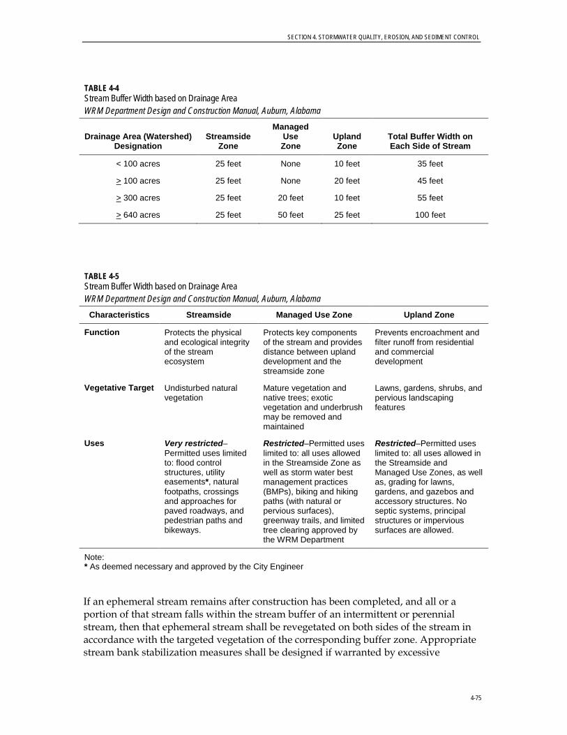
SECTION 4. STORMWATER QUALITY, EROSION, AND SEDIMENT CONTROL
4-75
TABLE 4-4 Stream Buffer Width based on Drainage Area WRM Department Design and Construction Manual, Auburn, Alabama
Drainage Area (Watershed) Designation
Streamside Zone
Managed Use Zone
Upland Zone
Total Buffer Width on Each Side of Stream
< 100 acres 25 feet None 10 feet 35 feet
> 100 acres 25 feet None 20 feet 45 feet
> 300 acres 25 feet 20 feet 10 feet 55 feet
> 640 acres 25 feet 50 feet 25 feet 100 feet
TABLE 4-5 Stream Buffer Width based on Drainage Area WRM Department Design and Construction Manual, Auburn, Alabama
Characteristics Streamside Managed Use Zone Upland Zone
Function Protects the physical and ecological integrity of the stream ecosystem
Protects key components of the stream and provides distance between upland development and the streamside zone
Prevents encroachment and filter runoff from residential and commercial development
Vegetative Target Undisturbed natural vegetation
Mature vegetation and native trees; exotic vegetation and underbrush may be removed and maintained
Lawns, gardens, shrubs, and pervious landscaping features
Uses Very restricted–Permitted uses limited to: flood control structures, utility easements*, natural footpaths, crossings and approaches for paved roadways, and pedestrian paths and bikeways.
Restricted–Permitted uses limited to: all uses allowed in the Streamside Zone as well as storm water best management practices (BMPs), biking and hiking paths (with natural or pervious surfaces), greenway trails, and limited tree clearing approved by the WRM Department
Restricted–Permitted uses limited to: all uses allowed in the Streamside and Managed Use Zones, as well as, grading for lawns, gardens, and gazebos and accessory structures. No septic systems, principal structures or impervious surfaces are allowed.
Note: * As deemed necessary and approved by the City Engineer
If an ephemeral stream remains after construction has been completed, and all or a portion of that stream falls within the stream buffer of an intermittent or perennial stream, then that ephemeral stream shall be revegetated on both sides of the stream in accordance with the targeted vegetation of the corresponding buffer zone. Appropriate stream bank stabilization measures shall be designed if warranted by excessive

SECTION 4. STORMWATER QUALITY, EROSION, AND SEDIMENT CONTROL
4-76
velocities in the ephemeral stream. If the ephemeral stream remains after construction and falls outside of an intermittent/perennial stream buffer, then that ephemeral stream shall be grassed and/or revegetated in accordance with the surrounding vegetation at a width of 25 feet on each side of the ephemeral stream. Ephemeral stream channels and banks shall be stabilized as appropriate for the predicted stream velocities. These measures are performed to preserve and protect water quality.
Applicability. The buffer requirements shall apply to all perennial and intermittent streams as defined in this subsection. Buffer widths for streams are measured horizontally on a line perpendicular to the surface water, landward from the top of the bank on each side of the stream. The top of bank is the landward edge of the stream channel during high water or bank full conditions at the point where the water leaves the stream channel and begins to overflow onto the floodplain.
All properties shall be subject to the buffer width requirements except those properties that are an existing lot of record and/or included on an approved preliminary subdivision plat and the lot or lots cannot meet the requirements described in this subsection (Effective date 5/02/06 pursuant to Ordinance Number 2389).
Minimize Intrusion. Any uses allowed in Table 4-5 shall be designed and constructed to minimize the amount of intrusion into the stream buffer and to minimize clearing, grading, erosion, and water quality degradation.
Land in the Stream Buffer. Land in stream buffers shall not be used for principal structures. All new platted lots shall be designed to provide sufficient land outside of the stream buffer to accommodate primary structures. Stream buffers should be delineated before streets and lots are laid out to minimize buffer intrusion and to ensure there is adequate buildable area on each platted lot.
Land within the stream buffer can serve to meet the minimum lot size requirements.
Setback Requirements. For all lots within a development requiring a stream buffer, setbacks can be 100 percent within the stream buffer.
Buffer Impact. When the application of the buffer zones would result in the loss of buildable area on a lot that was recorded prior to the effective date of these regulations, then modifying the width of the buffer zones may be allowed, through an administrative process, as determined by the WRM Department.
Modification and mitigation of the stream buffer width also are available to landowners or developers of newly platted lots or subdivisions where there are exceptional situations or physical conditions on the parcel that pose practical difficulty to its development and restrict the application of these regulations. There must be proof of such circumstances by the landowner.

SECTION 4. STORMWATER QUALITY, EROSION, AND SEDIMENT CONTROL
4-77
The landowner or his designated representative proposing any of the impacts shall prepare and submit for approval a written request and a site plan showing the extent of the proposed impact and must specify a proposed mitigation technique. Mitigation techniques are described in this subsection.
The WRM Department and other appropriate city staff members shall review and render a decision on any buffer encroachment and mitigation technique with regard to the stream buffer requirements. Amendment to the stream buffer width may be allowed in accordance with the following criteria:
A. The proposed encroachment and mitigation is in accordance with the purpose and intent of this section of the ordinance.
B. The proposed lot and structure conforms to all other zoning and development regulations.
C. Encroachments into the buffer areas shall be the minimum necessary to achieve a reasonable buildable area for a principal structure and necessary utility.
D. The landowner or his designated representative submitted an acceptable written statement justifying the need for the buffer impact.
E. The landowner or his designated representative submitted an acceptable mitigation plan in accordance with cited mitigation techniques.
F. Attention has been given to maintaining natural vegetation and eliminating runoff.
In no case shall the reduced portion of the buffer area be less than the width of the Streamside Zone (25 feet).
Stream Buffer Mitigation Techniques. The following techniques are available to landowners for the mitigation of buffer impact:
A. Installation of Structural BMPs. The installation of an onsite structural BMP (i.e., bioretention, extended detention and retention, rain gardens, stormwater wetlands, etc.) will allow for stream buffer impacts on the specific site. The structural BMP shall be designed to achieve pollutant (nutrients, herbicides, pesticides, sediment, and other illicit discharges) removal to the maximum extent practicable. The BMP shall remain outside the Streamside Zone. A detailed BMP design plan must be submitted to the City Engineer for approval, along with a long-term maintenance plan.
B. Controlled Impervious Surface. The landowner may commit to and provide a specific site development plan that limits the overall site impervious surface ratio equal to or less than 25 percent.
C. Open Space Development. The landowner may submit a specific site development plan which preserves an undisturbed, vegetative area onsite or near the development site as open space equal to 200 percent of the buffer encroachment area. The open space preserved must promote water quality protection.
SECTION 4. STORMWATER QUALITY, EROSION, AND SEDIMENT CONTROL
4-78
D. Stream Restoration: The landowner may restore and preserve the buffer area on any stream of equivalent or greater drainage area the condition of which is determined to be qualified for restoration by the City Engineer on a 1:1 basis in linear feet of stream. This restoration shall include stream bank improvements and Streamside and Managed Use Zone re-vegetation.
E. Stream Preservation: The landowner may purchase, fee simple, other stream segments within the City limits at equivalent or greater drainage area on a 1:1 linear foot basis and convey fee simple and absolute title of the land to the City.
F. Wetland Restoration: On a 2:1 acreage basis for disturbed stream and buffer area (2 acres of wetland for each acre of disturbed area), the landowner may provide a combination of the preservation and/or restoration of wetlands with protective easements, and the implementation of structural or non-structural BMPs to achieve pollutant removal to the maximum extent practicable.
G. Greenways: The landowner may allocate and donate open space within the City limits through fee simple to the City for preservation and use as common open space.
H. Wider Buffer Widths: A developer may add additional widths to buffer areas where encroachment occurs in other areas on a development site and may obtain an acre-for-acre credit based on the stream buffer zone affected. A 2:1 credit could be obtained by determination of the WRM Department in the event additional streamside buffer is set aside for encroachment of the managed use and upland stream buffer zones.
I. Other Mitigation Techniques: Other creative mitigation techniques and plans may be considered by the WRM Department.
Vegetation Preservation. The buffer shall provide for the preservation and enhancement of natural vegetation or planting. No live vegetation may be removed from the Streamside and Managed Use Zones for preparation of land for uses permitted in Table 4-5 unless approved by the WRM Department.
The WRM Department may grant approval of the removal of exotic vegetation (i.e., privet, kudzu, etc.) provided that a vegetation restoration plan is submitted and approved prior to the disturbance of the vegetation. The purpose of such plan is to ensure that native vegetation is restored to the Streamside Zone.
Where a developer or lot owner removes live vegetation from the buffer strip, in violation of this subsection, the WRM Department shall require native vegetation of reasonable diameter in size to be planted so as to create a buffer area that is in compliance with this subsection. A vegetation restoration plan must be submitted and approved by the WRM Department prior to restoration.
SECTION 4. STORMWATER QUALITY, EROSION, AND SEDIMENT CONTROL
4-79
Vegetation Restoration Plan. A vegetation restoration plan shall include the following information:
A. Scaled map of lot showing buffer delineation (copy of the survey is acceptable).
B. Square footage of the actual area disturbed or the proposed disturbed area.
C. Proposed vegetation to be removed from the buffer.
D. Proposed location, number, and species of plants to be planted in the disturbed area. A list of suitable plant species is available from the Watershed Division of the WRM Department.
E. Type of ground cover to be placed in the disturbed area (i.e., mulch, pine straw, etc.).
F. Proposed planting schedule and deadline for the completion of the restoration activities.
Approved Permits. Where a landowner or his/her representative obtain permits from ADEM or the USACE for proposed impacts to the stream or stream buffers, then these approved mitigation impacts and plans would supersede the applicable requirements of these sections of the ordinance. The regulations that these permits do not affect shall be applicable to the proposed development site.
4.4.7.6 Monitoring and Maintenance The vegetative structure throughout the buffer must be maintained. The buffer should be monitored to evaluate its success and plant material should be replaced as necessary. Conditions to be investigated and corrected include damaged livestock fences, streambank erosion and washout, disease and insect infestation, dead plants, invasive species, gullies caused by concentrated flow, and damage by wildlife.
Maintenance must be carried out with minimal impact in the zone closest to the stream. Watering may be necessary in the initial year or during periods of drought, especially if bare root vegetation is installed. Ongoing maintenance activities include selective cutting, replanting to maintain forest structure, and weed control. Fertilization and liming are recommended during plant establishment. Long-term fertilization, however, should not be necessary if the proper vegetation has been selected. Weeds can be suppressed by planting vigorous species that can compete successfully, and by ensuring that the nutritional needs of the plants are met.
Eradicating invasive plant species such as Japanese honeysuckle (Lonicera japonica), kudzu (Pueraria lobata), and privet (Ligustrum spp.) may be necessary to ensure that forest structure and diversity are maintained. Measures also may need to be taken to prevent wildlife from damaging seedlings by browsing. If the streambank structure is not maintained by riparian vegetation, then additional measures should be used such as live staking, intercepting runoff before it enters the riparian forested buffer, or using stabilization techniques.
SECTION 4. STORMWATER QUALITY, EROSION, AND SEDIMENT CONTROL
4-80
Riparian buffers require maintenance to do the following:
• Repair fences • Fill gullies • Remove weeds and invasive vegetation • Repair stream bank erosion • Protect against wildlife damage and insect and disease problems • Replant to maintain the proper stand density • Provide periodic vegetative thinning and harvesting of mature trees to maintain
health and growth
4.4.8 Permeable Pavement (also known as Pervious Pavement) 4.4.8.1 Description and Benefits Permeable pavement is an alternative to conventional concrete and asphalt paving materials that allows for rapid infiltration of stormwater. Stormwater infiltrates though the permeable pavement to a gravel substrate that provides temporary storage until the water infiltrates into underlying permeable soils or through an underground drain system.
Traditional paved surfaces, such as asphalt and concrete, do not allow water to infiltrate and convert almost all rainfall into runoff. If designed and implemented correctly, permeable pavement systems allow at least a portion of the stormwater to infiltrate. Modular permeable pavers typically are placed on a gravel (stone aggregate) base course. Runoff infiltrates through the permeable paver surface into the gravel base course, which acts as a storage reservoir as it exfiltrates to the underlying soil. The infiltration rate of the soils in the subgrade must be adequate to support drawdown of the entire runoff capture volume within 24 to 48 hours. Special care must be taken during construction to avoid undue compaction of the underlying soils, which could affect the infiltration capability of the soil. Permeable pavement systems are designed to do the following:
• Reduce peak runoff volumes • More effectively manage stormwater flows
Permeable paving materials include, but are not necessarily limited to, porous concrete, permeable interlocking concrete pavers, concrete grid pavers, and porous asphalt.
Estimated Pollutant Removal Efficiency Rates • TSS ~ not applicable • Nutrients (TP/TN) ~ 80/
80 percent • Metals ~ 90 percent
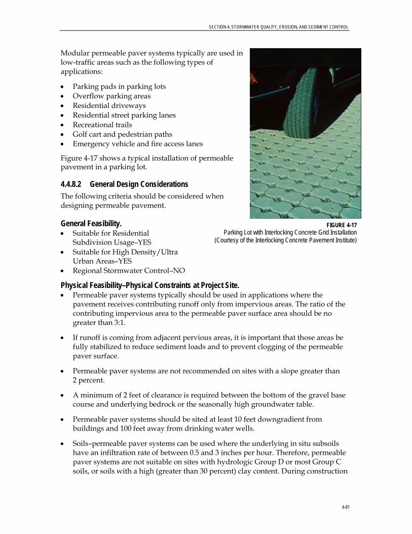
SECTION 4. STORMWATER QUALITY, EROSION, AND SEDIMENT CONTROL
4-81
Modular permeable paver systems typically are used in low-traffic areas such as the following types of applications:
• Parking pads in parking lots • Overflow parking areas • Residential driveways • Residential street parking lanes • Recreational trails • Golf cart and pedestrian paths • Emergency vehicle and fire access lanes
Figure 4-17 shows a typical installation of permeable pavement in a parking lot.
4.4.8.2 General Design Considerations The following criteria should be considered when designing permeable pavement.
General Feasibility. • Suitable for Residential
Subdivision Usage–YES • Suitable for High Density/Ultra
Urban Areas–YES • Regional Stormwater Control–NO
Physical Feasibility–Physical Constraints at Project Site. • Permeable paver systems typically should be used in applications where the
pavement receives contributing runoff only from impervious areas. The ratio of the contributing impervious area to the permeable paver surface area should be no greater than 3:1.
• If runoff is coming from adjacent pervious areas, it is important that those areas be fully stabilized to reduce sediment loads and to prevent clogging of the permeable paver surface.
• Permeable paver systems are not recommended on sites with a slope greater than 2 percent.
• A minimum of 2 feet of clearance is required between the bottom of the gravel base course and underlying bedrock or the seasonally high groundwater table.
• Permeable paver systems should be sited at least 10 feet downgradient from buildings and 100 feet away from drinking water wells.
• Soils–permeable paver systems can be used where the underlying in situ subsoils have an infiltration rate of between 0.5 and 3 inches per hour. Therefore, permeable paver systems are not suitable on sites with hydrologic Group D or most Group C soils, or soils with a high (greater than 30 percent) clay content. During construction
FIGURE 4-17 Parking Lot with Interlocking Concrete Grid Installation
(Courtesy of the Interlocking Concrete Pavement Institute)
SECTION 4. STORMWATER QUALITY, EROSION, AND SEDIMENT CONTROL
4-82
and preparation of the subgrade, special care must be taken to avoid compaction of the soils.
Other Constraints/Considerations. • Permeable paver system designs must use some method to convey larger storm
event flows to the conveyance system. One option is to use storm drain inlets set slightly above the elevation of the pavement. This approach would allow for some ponding above the surface, but would accept bypass flows that are too large to be infiltrated by the permeable paver system, or if the surface clogs.
• For the purpose of sizing downstream conveyance and structural control systems, permeable paver surface areas can be assumed to be 40-percent impervious.
4.4.8.3 Advantages • Reduces stormwater runoff rate and volume.
• Reduces the loads of some pollutants in surface runoff by reducing the volume of stormwater leaving a site.
• Can be a potential component of LID site designs.
4.4.8.4 Disadvantages • Potential for sediment to clog porous media, which would lead to reduced
effectiveness.
• High maintenance requirements.
• Higher cost than conventional pavements.
• Special attention to design and construction required.
• Not applicable for high-traffic areas or for use by heavy vehicles.
• Completed permeable pavement installation must have a slope less than 2 percent.
4.4.8.5 Design Procedures • An appropriate modular porous paver should be selected for the intended
application. A minimum of 40 percent of the surface area should consist of open void space. If it is a load-bearing surface, then the pavers should be able to support the maximum load.
• The porous paver infill is selected based upon the intended application and required infiltration rate. Masonry sand (such as ASTM C-33 concrete sand or ALDOT Fine Aggregate Size No. 10) has a high infiltration rate (8 inches per hour [in./hr]) and should be used in applications where no vegetation is desired. A sandy loam soil has a substantially lower infiltration rate (1 in./hr), but will provide for growth of a grass ground cover.
• A 1-inch top course (filter layer) of sand (ASTM C-33 concrete sand or ALDOT Fine Aggregate Size No. 10) underlain by filter fabric is placed under the porous pavers and above the gravel base course.

SECTION 4. STORMWATER QUALITY, EROSION, AND SEDIMENT CONTROL
4-83
• The gravel base course should be designed to store, at a minimum, the WQv. The stone aggregate used should be washed, bank-run gravel, 1.5 to 2.5 inches in diameter, with a void space of about 40 percent (ALDOT No. 3 Stone). Aggregate contaminated with soil shall not be used. A porosity value (void space/total volume) of 0.32 should be used in calculations.
• The gravel base course must have a minimum depth of 9 inches. The following equation can be used to determine whether the depth of the storage layer (gravel base course) needs to be greater than the minimum depth:
d = V / A * n where: d = Gravel Layer Depth (ft) V = Water Quality Volume –or– Total Volume to be Infiltrated A = Surface Area (ft2) n = Porosity (use n=0.32)
• The surface of the subgrade should be lined with filter fabric or an 8-inch layer of sand (ASTM C-33 concrete sand or ALDOT Fine Aggregate Size No. 10) and be completely flat to promote infiltration across the entire surface.
• For impermeable clays and soils with infiltration rates less than 0.5 in./hr, a perforated underdrain system (with clean-outs) connected to storm drain piping should be used with permeable pavement. The underdrain system should be made of 6-inch perforated or slotted Schedule 40 PVC pipe. The underdrain should be wrapped in filter fabric or embedded in a 1-foot-thick layer of clean sand.
4.4.8.6 Design Example The sizing and the design of permeable pavement are site dependent and usually are performed by the selected manufacturer. Figure 4-18 shows a cross-section and some examples of permeable pavement.
4.4.8.7 Monitoring and Maintenance Permeable pavement installations should be monitored regularly to ensure that sediment clogs are not inhibiting infiltration. Maintenance requirements are critical for the success of permeable pavement. The installation and maintenance requirements listed in Table 4-6 are designed to ensure that the permeable pavement system will work effectively.

SECTION 4. STORMWATER QUALITY, EROSION, AND SEDIMENT CONTROL
4-84
FIGURE 4-18
Typical Permeable Paver Design
TABLE 4-6 Required Maintenance Activities for Permeable Pavement Installations WRM Department Design and Construction Manual, Auburn, Alabama
Activity Schedule
Initial inspection Monthly for 3 months after installation
Ensure that permeable pavement surface is free of sediment Monthly
Ensure that the contributing and adjacent area is stabilized and mowed, with clippings removed
As needed, based on inspection
Vacuum sweep permeable pavement surface Annually
Inspect the surface for deterioration Annually
Verify that the permeable pavement system dewaters between storms Annually
Verify that underdrain outlet is free from obstructions (if applicable) Annually
Note: Adopted from Atlanta Regional Commission and Georgia Department of Natural Resources, 2001.

SECTION 4. STORMWATER QUALITY, EROSION, AND SEDIMENT CONTROL
4-85
4.4.9 Sand Filter 4.4.9.1 Description and Benefits A sand filter is a device that allows stormwater to percolate down through sand layers and possibly a topsoil layer. Common usage areas for this type of BMP are parking lots, driveways, loading docks, service stations, garages, airports, and storage yards.
The two types of sand filters presented in this Manual are: 1) surface or open sand filter; and 2) perimeter or closed sand filter. The surface sand filters can treat larger drainage areas than can the perimeter sand filters. A surface sand filter facility consists of a two-chamber open-air structure, which is located at ground-level. The first chamber is the sediment forebay (that is, the sedimentation chamber), while the second chamber is the sand filter bed. Flow enters the sedimentation chamber, where settling of larger sediment particles occurs. Runoff is then discharged from the sedimentation chamber through a perforated standpipe into the filtration chamber. After passing though the filter bed, runoff is collected by a perforated pipe and gravel underdrain system. Figure 4-19 provides plan view and profile schematics of a surface sand filter. A variation of the open sand filter, the open organic filter, is used when maximum nutrient or trace metal removals are desired.
A perimeter or closed sand filter facility is a vault structure located just below grade level. Runoff enters the device through inlet grates along the top of the structure into the sedimentation chamber. Runoff is discharged from the sedimentation chamber through a weir into the filtration chamber. After passing though the filter bed, runoff is collected by a perforated pipe and gravel underdrain system. In a closed sand filter, runoff is collected in underground pipes and discharged to a drain, but water is not infiltrated into the groundwater. This method obtains the benefits of sand filtration without the potential groundwater contamination.
Studies show that properly designed, constructed, and maintained sand filters are considered one of the more effective BMPs at managing the following:
• Fecal coliform • Oxygen-demanding substances • Sediment • TSS
A sand filter also can aid in reducing the following pollutants:
• Nutrients (TN, total Kjeldahl nitrogen [TKN], and TP) • Trace metals including lead, zinc, and copper • Hydrocarbons
Estimated Pollutant Removal Efficiency Rates The efficiency rates for both open and closed sand filters are similar, as follows:
• TSS ~ 80 percent • Nutrients (TP/TN) ~ 50/25
percent • Metals ~ 50 percent • Pathogens ~ 40 percent
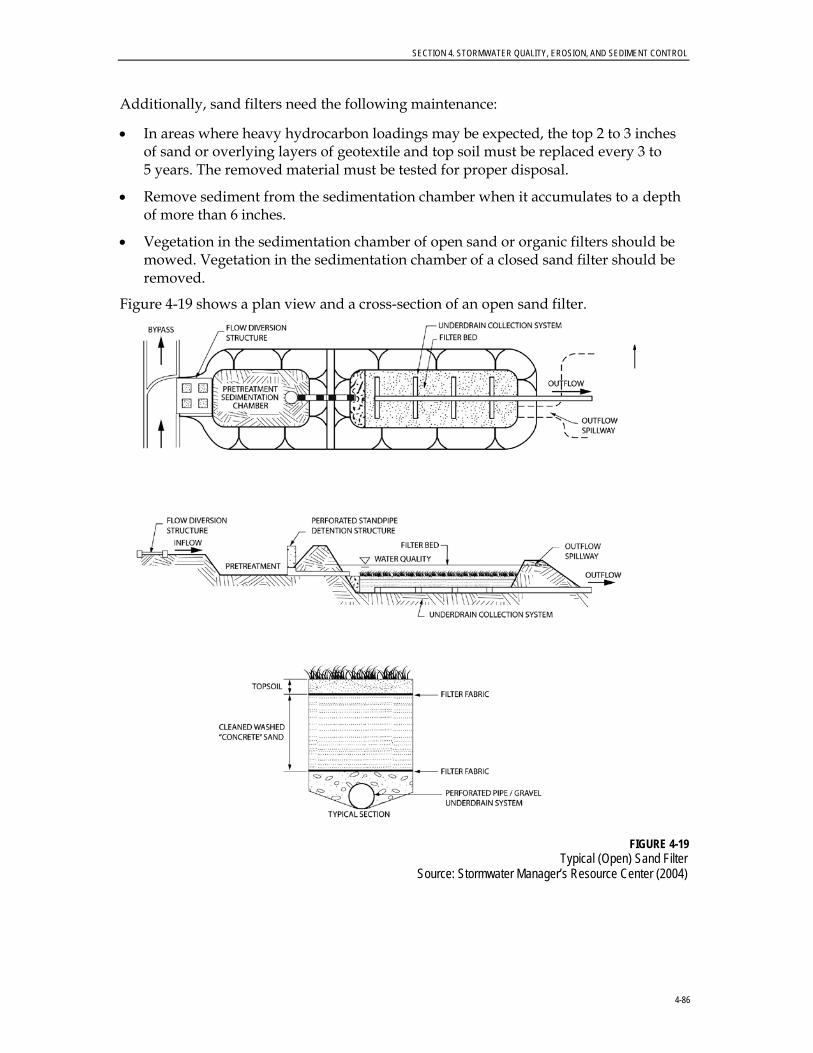
SECTION 4. STORMWATER QUALITY, EROSION, AND SEDIMENT CONTROL
4-86
Additionally, sand filters need the following maintenance:
• In areas where heavy hydrocarbon loadings may be expected, the top 2 to 3 inches of sand or overlying layers of geotextile and top soil must be replaced every 3 to 5 years. The removed material must be tested for proper disposal.
• Remove sediment from the sedimentation chamber when it accumulates to a depth of more than 6 inches.
• Vegetation in the sedimentation chamber of open sand or organic filters should be mowed. Vegetation in the sedimentation chamber of a closed sand filter should be removed.
Figure 4-19 shows a plan view and a cross-section of an open sand filter.
FIGURE 4-19
Typical (Open) Sand Filter Source: Stormwater Manager’s Resource Center (2004)

SECTION 4. STORMWATER QUALITY, EROSION, AND SEDIMENT CONTROL
4-87
4.4.9.2 General Design Considerations The following criteria should be considered when designing sand filters.
General Feasibility. • Suitable for Residential Subdivision Usage–NO • Suitable for High Density/Ultra Urban Areas–YES • Regional Stormwater Control–NO
Physical Feasibility–Physical Constraints at Project Site. • Drainage Area–10 acres maximum for surface sand filter; 2 acres maximum for
perimeter sand filter.
• Space Required–Function of available head at a site.
• Site Slope–No more than a 6-percent slope across filter location.
• Minimum Head–5 feet of elevation difference needed at a site from the inflow to the outflow.
• Minimum Depth to Water Table–For a surface sand filter with exfiltration (earthen structure), 2 feet are required between the bottom of the sand filter and the elevation of the seasonally high water table.
• Soils–No restrictions; Group “A” soils generally required to allow exfiltration (for surface sand filter earthen structure).
Other Constraints/Considerations. • Aquifer Protection–Do not allow exfiltration of filtered hot spot runoff into
groundwater.
4.4.9.3 Advantages • Highly effective at filtering TSS.
• Can filter flows from moderate to large areas.
• Larger units can attenuate runoff peaks, particularly if the design storm is not large (less than 10-year return period).
• Underground closed filters are useful where space is limited.
• Perimeter closed filters are useful for small sites that have flat terrain or a high water table.
4.4.9.4 Disadvantages • Need to integrate trash screens or grated inlets in all designs so materials that can
cause premature failures are kept out of filter chambers. Frequent cleaning of these screens may be required. Clogging of the sand filter materials can limit the life span of the BMP.
• If anoxic conditions develop in the sand filter, phosphorus levels can increase as water passes through the sand filter.
• May not be effective in controlling peak discharges.

SECTION 4. STORMWATER QUALITY, EROSION, AND SEDIMENT CONTROL
4-88
• Large sand filters without grass cover may not be attractive in residential areas.
• When used in some settings, trash accumulation on the surface of sand filters can be unattractive.
4.4.9.5 Design Procedure Step 1. Compute runoff control volumes
• Calculate the WQv for the drainage area using the City’s Site Development Review Tool.
Step 2. Determine if the development site and conditions are appropriate for the use of a sand filter
• Refer to the site selection criteria listed in Section 4.6 of this Manual.
Step 3. Size flow diversion structure, if needed • A flow regulator (or flow splitter diversion structure) should be supplied to divert
the WQv to the sand filter facility.
• Size the low-flow orifice, weir, or other device to pass the Qwq.
Step 4. Size filtration basin chamber • The filter area is sized using the following equation (based on Darcy’s Law):
Af = (WQv) (df) / [(k) (hf + df) (tf)]
where: Af = surface area of filter bed (ft2) df = filter bed depth (typically 18 inches, no more than 24 inches) k = coefficient of permeability of filter media (ft/day) (use 3.5 ft/day for sand) hf = average height of water above filter bed (ft) (1/2 hmax, which varies based on site but hmax is typically ≤ 6 feet) tf = design filter bed drain time (days) (1.67 days or 40 hours is recommended maximum)
• Set the preliminary dimensions of the filtration basin chamber.
Step 5. Determine the physical specifications and geometry
Surface or Open Sand Filter
• The entire treatment system (including the sedimentation chamber) must temporarily hold at least 75 percent of the WQv prior to filtration. Figure 4-20 illustrates the distribution of the treatment volume (0.75 WQv) among the various components of the surface sand filter, including the following:
− Vs–volume within the sedimentation basin − Vf–volume within the voids in the filter bed − Vf-temp–temporary volume stored above the filter bed − As–the surface area of the sedimentation basin − Af–surface area of the filter media − hs–height of water in the sedimentation basin
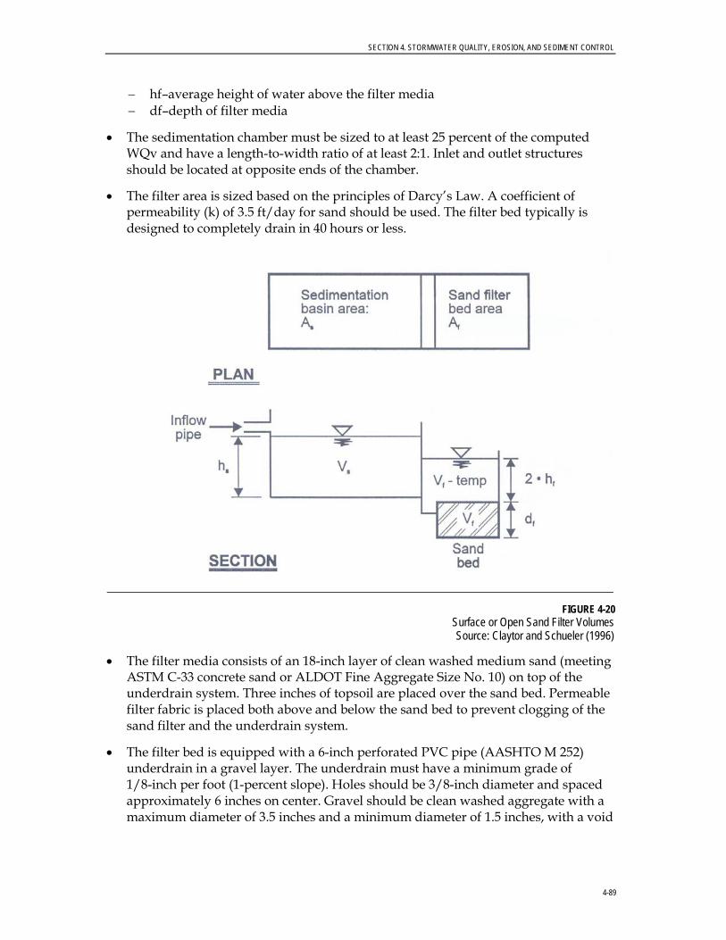
SECTION 4. STORMWATER QUALITY, EROSION, AND SEDIMENT CONTROL
4-89
− hf–average height of water above the filter media − df–depth of filter media
• The sedimentation chamber must be sized to at least 25 percent of the computed WQv and have a length-to-width ratio of at least 2:1. Inlet and outlet structures should be located at opposite ends of the chamber.
• The filter area is sized based on the principles of Darcy’s Law. A coefficient of permeability (k) of 3.5 ft/day for sand should be used. The filter bed typically is designed to completely drain in 40 hours or less.
FIGURE 4-20 Surface or Open Sand Filter Volumes Source: Claytor and Schueler (1996)
• The filter media consists of an 18-inch layer of clean washed medium sand (meeting ASTM C-33 concrete sand or ALDOT Fine Aggregate Size No. 10) on top of the underdrain system. Three inches of topsoil are placed over the sand bed. Permeable filter fabric is placed both above and below the sand bed to prevent clogging of the sand filter and the underdrain system.
• The filter bed is equipped with a 6-inch perforated PVC pipe (AASHTO M 252) underdrain in a gravel layer. The underdrain must have a minimum grade of 1/8-inch per foot (1-percent slope). Holes should be 3/8-inch diameter and spaced approximately 6 inches on center. Gravel should be clean washed aggregate with a maximum diameter of 3.5 inches and a minimum diameter of 1.5 inches, with a void

SECTION 4. STORMWATER QUALITY, EROSION, AND SEDIMENT CONTROL
4-90
space of about 40 percent (ALDOT No. 3 Stone). Aggregate contaminated with soil shall not be used.
• The surface sand filter may be constructed of impermeable media such as concrete, or through the use of excavations and earthen embankments. When constructed with earthen walls and embankments, filter fabric should be used to line the bottom and side slopes of the structures before the installation of the underdrain system and filter media.
Perimeter or Closed Sand Filter
• The entire treatment system (including the sedimentation chamber) must temporarily hold at least 75 percent of the WQv prior to filtration. Figure 4-21 illustrates the distribution of the treatment volume (0.75 WQv) among the various components of the perimeter sand filter, including the following:
• Vw–wet pool volume within the sedimentation basin • Vf–volume within the voids in the filter bed • Vtemp–temporary volume stored above the filter bed • As–the surface area of the sedimentation basin • Af–surface area of the filter media • hf–average height of water above the filter media (1/2 htemp) • df–depth of filter media
FIGURE 4-21
Perimeter or Closed Sand Filter Volumes Source: Claytor and Schueler (1996)
• The sedimentation chamber must be sized to at least 50 percent of the computed WQv.
• The filter area is sized based on the principles of Darcy’s Law. A coefficient of permeability (k) of 3.5 ft/day for sand should be used. The filter bed typically is designed to completely drain in 40 hours or less.
• The filter media should consist of a 12- to 18-inch layer of clean washed medium sand (meeting ASTM C-33 concrete sand or ALDOT Fine Aggregate Size No. 10) on top of the underdrain system. Figure 4-22 illustrates a typical media cross section.

SECTION 4. STORMWATER QUALITY, EROSION, AND SEDIMENT CONTROL
4-91
FIGURE 4-22 Typical Sand Filter Media Cross Sections
Source: Claytor and Schueler (1996)
• The perimeter sand filter is equipped with a 4-inch perforated PVC pipe (AASHTO M 252) underdrain in a gravel layer. The underdrain must have a minimum grade of 1/8 inch per foot (1-percent slope). Holes should be 3/8-inch diameter and spaced approximately 6 inches on center. A permeable filter fabric should be placed between the gravel layer and the filter media. Gravel should be clean washed aggregate with a maximum diameter of 3.5 inches and a minimum diameter of 1.5 inches, with a void space of about 40 percent (ALDOT No.3 Stone). Aggregate contaminated with soil shall not be used.
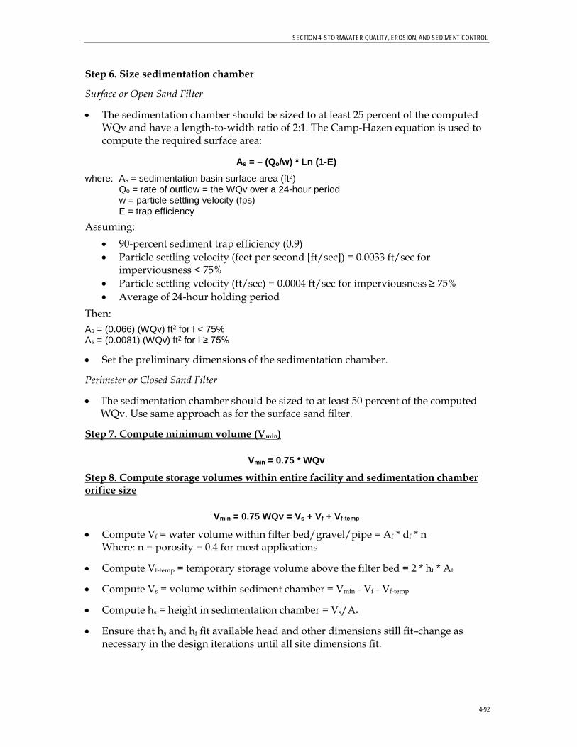
SECTION 4. STORMWATER QUALITY, EROSION, AND SEDIMENT CONTROL
4-92
Step 6. Size sedimentation chamber
Surface or Open Sand Filter
• The sedimentation chamber should be sized to at least 25 percent of the computed WQv and have a length-to-width ratio of 2:1. The Camp-Hazen equation is used to compute the required surface area:
As = – (Qo/w) * Ln (1-E)
where: As = sedimentation basin surface area (ft2) Qo = rate of outflow = the WQv over a 24-hour period w = particle settling velocity (fps) E = trap efficiency
Assuming: • 90-percent sediment trap efficiency (0.9) • Particle settling velocity (feet per second [ft/sec]) = 0.0033 ft/sec for
imperviousness < 75% • Particle settling velocity (ft/sec) = 0.0004 ft/sec for imperviousness ≥ 75% • Average of 24-hour holding period
Then: As = (0.066) (WQv) ft2 for I < 75% As = (0.0081) (WQv) ft2 for I ≥ 75%
• Set the preliminary dimensions of the sedimentation chamber.
Perimeter or Closed Sand Filter
• The sedimentation chamber should be sized to at least 50 percent of the computed WQv. Use same approach as for the surface sand filter.
Step 7. Compute minimum volume (Vmin)
Vmin = 0.75 * WQv
Step 8. Compute storage volumes within entire facility and sedimentation chamber orifice size
Vmin = 0.75 WQv = Vs + Vf + Vf-temp
• Compute Vf = water volume within filter bed/gravel/pipe = Af * df * n Where: n = porosity = 0.4 for most applications
• Compute Vf-temp = temporary storage volume above the filter bed = 2 * hf * Af
• Compute Vs = volume within sediment chamber = Vmin - Vf - Vf-temp
• Compute hs = height in sedimentation chamber = Vs/As
• Ensure that hs and hf fit available head and other dimensions still fit–change as necessary in the design iterations until all site dimensions fit.
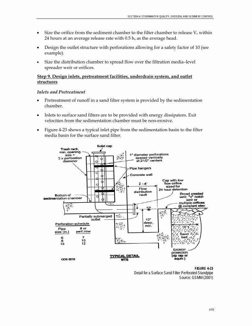
SECTION 4. STORMWATER QUALITY, EROSION, AND SEDIMENT CONTROL
4-93
• Size the orifice from the sediment chamber to the filter chamber to release Vs within 24 hours at an average release rate with 0.5 hs as the average head.
• Design the outlet structure with perforations allowing for a safety factor of 10 (see example).
• Size the distribution chamber to spread flow over the filtration media–level spreader weir or orifices.
Step 9. Design inlets, pretreatment facilities, underdrain system, and outlet structures Inlets and Pretreatment
• Pretreatment of runoff in a sand filter system is provided by the sedimentation chamber.
• Inlets to surface sand filters are to be provided with energy dissipators. Exit velocities from the sedimentation chamber must be non-erosive.
• Figure 4-23 shows a typical inlet pipe from the sedimentation basin to the filter media basin for the surface sand filter.
FIGURE 4-23
Detail for a Surface Sand Filter Perforated Standpipe Source: GSMM (2001)
SECTION 4. STORMWATER QUALITY, EROSION, AND SEDIMENT CONTROL
4-94
Underdrain System
• The filter bed is equipped with a 6-inch perforated PVC pipe (AASHTO M 252) underdrain in a gravel layer. The underdrain must have a minimum grade of 1/8-inch per foot (1-percent slope). Holes should be 3/8-inch diameter and spaced approximately 6 inches on center. Gravel should be clean washed aggregate with a maximum diameter of 3.5 inches and a minimum diameter of 1.5 inches, with a void space of about 40 percent. Aggregate contaminated with soil shall not be used.
Outlet Structures
• Outlet pipe is to be provided from the underdrain system to the facility discharge. Because of the slow rate of filtration, outlet protection generally is unnecessary (except for emergency overflows and spillways).
Step 10. Compute overflow weir sizes • Size overflow weir at elevation hs in sedimentation chamber (above perforated
stand pipe) to handle the surcharge of flow through the filter system from a 25-year storm.
• Plan inlet protection for overflow from the sedimentation chamber and size the overflow weir at elevation hf in the filtration chamber (above the perforated stand pipe) to handle the surcharge of flow through the filter system from a 25-year storm.
4.4.9.6 Design Example The following example focuses on the design of a sand filter to meet the water quality treatment requirements of the site. Channel protection and overbank flood control are not addressed in this example other than the quantification of preliminary storage volume and peak discharge requirements. In general, the primary function of sand filters is to provide water quality treatment, but not large storm attenuation. As such, flows in excess of the WQv typically are routed to bypass the facility. Where quantity control is required, the bypassed flows can be routed to conventional detention basins (or some other facility such as underground storage vaults). The layout of the Community Center is shown in Figure 4-24.
Base Data Site Area = Total Drainage Area (A) = 3.0 ac Impervious Area = 1.9 ac; or I =1.9/3.0 = 63.3% Soils Type “C”
Hydrologic Data Pre Project CN = 57; Post Project CN = 88 Pre Project tc = 0.39; Post Project tc = 0.2

SECTION 4. STORMWATER QUALITY, EROSION, AND SEDIMENT CONTROL
4-95
FIGURE 4-24
Sand Filter Example Site Plan Source: GSMM (2001)
Step 1. Compute runoff control volumes
Water Quality Volume On the basis of the site data listed above, the calculated WQv for the sand filter is 0.186 ac-ft.
Stream Channel Protection Volume (Cpv) For stream channel protection, provide 24 hours of ED for the 1-year event:
Condition CN Q1-year Q1-year Q25-year Q100-year Inches cfs cfs cfs
Pre-developed 57 0.5 0.6 6.0 9.0
Post-Developed 83 1.9 5.5 17.0 22.0
• Use a modified TR-55 approach to compute the Cpv Initial abstraction (Ia) for a CN of 83 is 0.41: (TR-55) [Ia = (200/CN - 2)]:
Ia/P = (0.41)/ 3.6 inches = 0.11 tc = 0.15 hours From TR-55 (NRCS, 1986): qu = 590 csm/in
SECTION 4. STORMWATER QUALITY, EROSION, AND SEDIMENT CONTROL
4-96
Knowing qu and T (ED time), find qo/qi for a Type II rainfall distribution:
Peak outflow discharge/peak inflow discharge (qo/qi) = 0.03
Vs/Vr = 0.683 - 1.43(qo/qi) +1.64(qo/qi) 2 - 0.804(qo/qi) 3
Where Vs equals the Cpv and Vr equals the volume of runoff in inches:
Vs/Vr = 0.64
Therefore, Vs = Cpv = 0.64(1.9”)(1/12)(3 ac) = 0.30 ac-ft = 13,068 ft3
• Define the average ED Release Rate:
The above volume, 0.30 ac-ft, is to be released over 24 hours.
(0.30 ac-ft × 43,560 ft2/ac) / (24 hrs × 3,600 sec/hr) = 0.15 cfs
Overbank Flood Protection Volume (Qp25):
For a Qin of 17 cfs and an allowable Qout of 6 cfs, the Vs necessary for 25-year control is 0.52 ac-ft or 22,677 ft3, under a developed CN of 83. Note that 7.9 inches of rain fall during this event, with 5.9 inches of runoff.
Safe Passage of 100-year Design Storm:
At final design, prove that the discharge conveyance channel is adequate to convey the 100-year event and discharge to receiving waters, or handle it with a peak flow control structure, typically the same one used for the overbank flood protection control. The stream Cpv should be calculated using TR-55 (USDA, 1986).
Symbol Control Volume Volume Required (cubic feet) Notes
WQv Water Quality 8,102
Cpv Channel Protection 13,068
Qp25 Overbank Flood Protection 22,677
Qf Extreme Flood Protection NA Provide safe passage for the 100-year event in
the final design.
Step 2. Determine if the development site and conditions are appropriate for the use of a sand filter
Site-specific Data:
The existing ground elevation at the facility location is 22 feet, mean sea level. Soil boring observations reveal that the seasonally high water table is at 13 feet and the underlying soil is silt loam (ML). The adjacent creek invert is at 12 feet.
SECTION 4. STORMWATER QUALITY, EROSION, AND SEDIMENT CONTROL
4-97
Step 3. Compute WQv peak discharge (Qwq) and Head
Water Quality Volume:
The WQv previously was determined to be 8,102 ft3.
Determine available head (Figure 4-25)
The low point at the parking lot is 23.5 feet. Subtract 2 feet to pass the Q25 discharge (21.5) and a half foot for the channel to the facility (21.0). The low point at the stream invert is 12. Set the outfall underdrain pipe 2 feet above the stream invert and add 0.5 feet to this value for the drain (14.5). Add to this value 8 inches for the gravel blanket over the underdrains and 18 inches for the sand bed (16.67). The total available head is 21.0 - 16.67, or 4.33 feet. Therefore, the average depth, hf, is (hf) = 4.33 feet/2, and hf = 2.17 feet.
The peak rate of discharge for the water quality design storm is needed for the sizing of offline diversion structures, such as sand filters and grass channels. Conventional SCS methods have been found to underestimate the volume and rate of runoff for rainfall events of less than 2 inches. This discrepancy in estimating runoff and discharge rates can lead to situations where a significant amount of runoff bypasses the filtering treatment practice because of an inadequately sized diversion structure and leads to the design of undersized bypass channels.
The following procedure can be used to estimate peak discharges for small storm events. It relies on the volume of runoff computed using the Small Storm Hydrology Method (Pitt, 1994) and uses the NRCS, TR-55 Graphical Peak Discharge Method (USDA, 1986). A brief description of the calculation procedure is presented below.
• Using the WQv, a corresponding CN is computed using the following equation:
CN = 1000/[10 + 5P +10Q - 10(Q² + 1.25 QP)½]
where P = rainfall, in inches (use 1.2 inches for the water quality storm) and Q = runoff volume, in inches (equal to WQV ÷ area)
• Once a CN is computed, the tc is computed
• Using the computed CN, tc and drainage area (A), in acres; the peak discharge (Qwq ) for the water quality storm is computed.
− Read initial abstraction (Ia) and compute Ia/P
− Read the unit peak discharge (qu) for appropriate tc

SECTION 4. STORMWATER QUALITY, EROSION, AND SEDIMENT CONTROL
4-98
FIGURE 4-25 Head Diagram
Source: GSMM (2001)
• Using the WQv, compute the water quality Qwq:
Qwq = qu*A*WQV
where Qwq = the peak discharge, in cfs qu = the unit peak discharge, in cfs/mi²/inch A = drainage area, in square miles WQv = Water Quality Volume, in watershed inches
For this example, the steps are as follows:
Compute a modified CN for 1.2 inches of rainfall
P = 1.2" Q = WQv ÷ area = (8,102 ft3 ÷ 3 ac ÷ 43,560 ft2/ac × 12 in/ft) = 0.74" CN = 1000/[10+5P+10Q-10(Q2+1.25*Q*P)½] = 1000/[10+5*1.2+10*0.74-10(0.742+1.25*0.74*1.2)½] = 95.01
Use CN = 95
For CN = 95 and the tc = 0.15 hours, compute the Qp for a 1.2-inch storm. With the CN = 95, a 1.2-inch storm will produce 0.74 inches of runoff. Ia = 0.105; therefore,

SECTION 4. STORMWATER QUALITY, EROSION, AND SEDIMENT CONTROL
4-99
Ia/P = 0.105/1.2 = 0.088. From Section 2.1, qu = 625 csm/in, and therefore, Qwq = (625 csm/in) (3.0 ac/640ac/sq mi.) (0.74") = 2.2 cfs.
Step 4. Size flow diversion structure (see Figure 4-26):
Size a low-flow orifice to pass 2.2 cfs with 1.5 feet of head using the Orifice equation:
Q = CA(2gh)1/2 ; 2.2 cfs = (0.6) (A) [(2) (32.2 ft/s2) (1.5')]1/2
A = 0.37 sq ft = πd2/4: d = 0.7' or 8.5"; use 9 inches
Size the 25-year overflow as follows: the 25-year water surface elevation is set at 923. Use a concrete weir to pass the 25-year flow (17 cfs) into a grassed overflow channel using the Weir equation. Assume 2 feet of head to pass this event. Overflow channel should be designed to provide sufficient energy dissipation (e.g., rip-rap, plunge pool, etc.) so that there will be non-erosive velocities:
Q = CLH3/2
17 = 3.1 (L) (2')1.5
L = 1.94'; use L = 2'-0" which sets flow diversion chamber dimension.
Weir wall elev. = 21.0. Set the low flow invert at: 21.0 - [1.5' + (0.5*9"*1ft/12")] = 19.13.
FIGURE 4-26
Flow Diversion Structure Source: GSMM (2001)
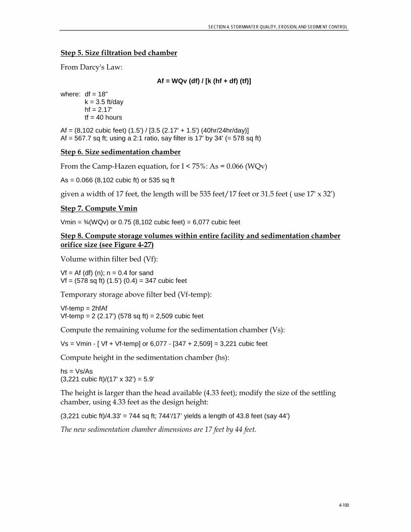
SECTION 4. STORMWATER QUALITY, EROSION, AND SEDIMENT CONTROL
4-100
Step 5. Size filtration bed chamber
From Darcy's Law:
Af = WQv (df) / [k (hf + df) (tf)]
where: df = 18" k = 3.5 ft/day hf = 2.17' tf = 40 hours
Af = (8,102 cubic feet) (1.5') / [3.5 (2.17' + 1.5') (40hr/24hr/day)] Af = 567.7 sq ft; using a 2:1 ratio, say filter is 17' by 34' (= 578 sq ft)
Step 6. Size sedimentation chamber
From the Camp-Hazen equation, for I < 75%: As = 0.066 (WQv)
As = 0.066 (8,102 cubic ft) or 535 sq ft
given a width of 17 feet, the length will be 535 feet/17 feet or 31.5 feet ( use 17' x 32’)
Step 7. Compute Vmin
Vmin = ¾(WQv) or 0.75 (8,102 cubic feet) = 6,077 cubic feet
Step 8. Compute storage volumes within entire facility and sedimentation chamber orifice size (see Figure 4-27)
Volume within filter bed (Vf):
Vf = Af (df) (n); n = 0.4 for sand Vf = (578 sq ft) (1.5') (0.4) = 347 cubic feet
Temporary storage above filter bed (Vf-temp):
Vf-temp = 2hfAf Vf-temp = 2 (2.17') (578 sq ft) = 2,509 cubic feet
Compute the remaining volume for the sedimentation chamber (Vs):
Vs = Vmin - [ Vf + Vf-temp] or 6,077 - [347 + 2,509] = 3,221 cubic feet
Compute height in the sedimentation chamber (hs):
hs = Vs/As (3,221 cubic ft)/(17' x 32') = 5.9'
The height is larger than the head available (4.33 feet); modify the size of the settling chamber, using 4.33 feet as the design height:
(3,221 cubic ft)/4.33' = 744 sq ft; 744’/17’ yields a length of 43.8 feet (say 44’)
The new sedimentation chamber dimensions are 17 feet by 44 feet.

SECTION 4. STORMWATER QUALITY, EROSION, AND SEDIMENT CONTROL
4-101
FIGURE 4-27
Sand Filter Site Plan View and Profile Source: GSMM (2001)

SECTION 4. STORMWATER QUALITY, EROSION, AND SEDIMENT CONTROL
4-102
With adequate preparation of the bottom of the settling chamber (rototil earth, place gravel, then surge stone), the bottom can infiltrate water into the substrate. The runoff will enter the groundwater directly without treatment. The stone will eventually clog without protection from settling solids, so use a removable geotextile to facilitate maintenance. Note that there are 2.17 feet of freeboard between the bottom of the recharge filter and the water table.
Provide a perforated standpipe with an orifice sized to release volume (within sedimentation basin) over a 24-hour period (see Figure 4-23). The average release rate equals 3,221 ft3/24 hr = 0.04 cfs.
The equivalent orifice size can be calculated using the orifice equation:
Q = CA(2gh)1/2 , where h is average head, or 4.33’/2 = 2.17’ 0.04 cfs = 0.6*A*(2*32.2 ft/s2*2.17 ft)1/2 A = 0.005 ft2 = πD2/4: therefore, equivalent orifice diameter equals 1”
The recommended design is to cap the stand pipe with a low-flow orifice sized for a 24-hour detention. Overperforate the pipe by a safety factor of 10 to account for clogging. Note that the size and number of perforations will depend on the release rate needed to achieve 24-hour detention. A multiple orifice stage-discharge relation needs to be developed for the proposed perforation configuration. The stand pipe should discharge into a flow distribution chamber prior to the filter bed. The distribution chamber should be between 2 and 4 feet in length and the same width as the filter bed. Flow distribution to the filter bed can be achieved either with a weir or with multiple orifices at a constant elevation. See Figure 4-23 for the stand pipe details.
Step 9. Design inlets, pretreatment facilities, underdrain system, and outlet structures
Step 10. Compute overflow weir sizes
Assume the overflow that needs to be handled is equivalent to the 9-inch orifice discharge under a head of 3.5 feet (i.e., the head in the diversion chamber associated with the 25-year peak discharge).
Q = CA(2gh)½
Q = 0.6(0.44 ft2)[(2)(32.2 ft/s2)(3.5 ft)]1/2 Q = 3.96 cfs, say 4.0 cfs
For the overflow from the sediment chamber to the filter bed, size to pass 4 cfs.
Weir equation:
Q = CLh3/2, assume a maximum allowable head of 0.5’
4.0 = 3.1 * L * (0.5 ft) 3/2 L = 3.65 ft, Use L = 3.75 ft.
Similarly, for the overflow from the filtration chamber to the outlet of the facility, size to pass 4 cfs.
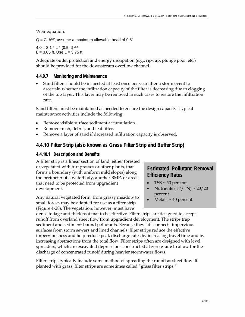
SECTION 4. STORMWATER QUALITY, EROSION, AND SEDIMENT CONTROL
4-103
Weir equation:
Q = CLh3/2, assume a maximum allowable head of 0.5’
4.0 = 3.1 * L * (0.5 ft) 3/2
L = 3.65 ft, Use L = 3.75 ft.
Adequate outlet protection and energy dissipation (e.g., rip-rap, plunge pool, etc.) should be provided for the downstream overflow channel.
4.4.9.7 Monitoring and Maintenance • Sand filters should be inspected at least once per year after a storm event to
ascertain whether the infiltration capacity of the filter is decreasing due to clogging of the top layer. This layer may be removed in such cases to restore the infiltration rate.
Sand filters must be maintained as needed to ensure the design capacity. Typical maintenance activities include the following:
• Remove visible surface sediment accumulation. • Remove trash, debris, and leaf litter. • Remove a layer of sand if decreased infiltration capacity is observed.
4.4.10 Filter Strip (also known as Grass Filter Strip and Buffer Strip) 4.4.10.1 Description and Benefits A filter strip is a linear section of land, either forested or vegetated with turf grasses or other plants, that forms a boundary (with uniform mild slopes) along the perimeter of a waterbody, another BMP, or areas that need to be protected from upgradient development.
Any natural vegetated form, from grassy meadow to small forest, may be adapted for use as a filter strip (Figure 4-28). The vegetation, however, must have dense foliage and thick root mat to be effective. Filter strips are designed to accept runoff from overland sheet flow from upgradient development. The strips trap sediment and sediment-bound pollutants. Because they “disconnect” impervious surfaces from storm sewers and lined channels, filter strips reduce the effective imperviousness and help reduce peak discharge rates by increasing travel time and by increasing abstractions from the total flow. Filter strips often are designed with level spreaders, which are excavated depressions constructed at zero grade to allow for the discharge of concentrated runoff during heavier stormwater flows.
Filter strips typically include some method of spreading the runoff as sheet flow. If planted with grass, filter strips are sometimes called “grass filter strips.”
Estimated Pollutant Removal Efficiency Rates • TSS ~ 50 percent • Nutrients (TP/TN) ~ 20/ 20
percent • Metals ~ 40 percent

SECTION 4. STORMWATER QUALITY, EROSION, AND SEDIMENT CONTROL
4-104
Filter strips can be effective in helping to manage the following:
• Sediment • Organic material • Metals
FIGURE 4-28
Filter Strip in Residential Area Adapted from Schueler (1987)
4.4.10.2 General Design Considerations The following criteria should be considered when designing filter strips.
General Feasibility. • Suitable for Residential Subdivision Usage–YES • Suitable for High Density/Ultra Urban Areas–NO • Regional Stormwater Control–NO
Physical Feasibility–Physical Constraints at Project Site. • Filter strips should be used to treat small drainage areas. Flow must enter the filter
strip as sheet flow spread out over the width (long dimension normal to flow) of the strip, generally no deeper than 1 to 2 inches. As a rule, flow concentrates within a maximum of 75 feet for impervious surfaces and 150 feet for pervious surfaces (Center for Watershed Protection [CWP], 1996). For longer flow paths, special provision must be made to ensure that the design flows spread evenly across the filter strip.
• Filter strips should be designed for slopes between 2 and 6 percent. Greater slopes than this would encourage the formation of concentrated flow. Flatter slopes would encourage standing water.
• The filter strip should be at least 15 feet long to provide filtration and contact time for water quality treatment. A length of 25 feet is preferred (where available), although the length normally will be dictated by the design method.
SECTION 4. STORMWATER QUALITY, EROSION, AND SEDIMENT CONTROL
4-105
• An effective flow spreader is to use a pea gravel diaphragm at the top of the slope (ASTM D 448 size No. 6, 1/8-inch to 3/8-inch). The pea gravel diaphragm (a small trench running along the top of the filter strip) serves two purposes. First, it acts as a pretreatment device, settling out sediment particles before they reach the practice. Second, it acts as a level spreader, maintaining sheet flow as runoff flows over the filter strip. Other types of flow spreaders include a concrete sill, curb stops, or curb and gutter with “sawteeth” cut into it.
Other Constraints/Considerations. • Pedestrian traffic across the filter strip should be limited through channeling onto
sidewalks.
• Filter strips should not be used on soils that cannot sustain a dense grass cover with high retardance. Designers should choose a grass that can withstand relatively high velocity flows at the entrances, and during both wet and dry periods.
4.4.10.3 Advantages • Can reduce particulate pollutants such as sediment, organic matter, and trace
metals.
• Slow down the water and promote infiltration.
• Can be implemented as part of landscaping requirements.
• Mesh well in residential areas where they provide open space for recreation, help maintain riparian zones, and reduce stream bank erosion.
4.4.10.4 Disadvantages • Not designed for high-velocity flows, so generally not applicable in large areas with
intense development or steep slopes.
• Need sheet flow to operate effectively; may be difficult to avoid flow concentration, which may lead to gullies.
• Do not provide enough runoff storage or infiltration to significantly reduce peak discharges or volume of storm runoff, so function only as one component in a stormwater management system.
4.4.10.5 Design Procedures Step 1: Compile contributing drainage area parameters
• Determine minimum filter strip size using Table 4-2.
• Calculate the contributing drainage area (A).
• Calculate the impervious percentage (I).
• Calculate the lope (S).
• Estimate Manning’s “n” value (n).

SECTION 4. STORMWATER QUALITY, EROSION, AND SEDIMENT CONTROL
4-106
Step 2: Calculate maximum discharge loading per foot of filter strip width
21
3500236.0 SY
nq =
Where: q = discharge per foot of width of filter strip (cfs/ft) Y = allowable depth of flow (inches) S = slope of filter strip (%) n = Manning’s “n” roughness coefficient. (use 0.15 for medium grass, 0.25 for dense grass, and 0.35 for very dense Bermuda-type grass)
Step 3. Compute runoff control volumes using the City’s Site Review Tool
• Compute WQv using the City’s Site Development Review Tool.
Step 4: Compute the water quality peak flow
• Compute the peak discharge for the water quality storm (Qwv) based on 1.2 inches of rainfall for Auburn, assuming a 24-hour storm duration.
Step 5: Compute the minimum width of the filter strip
• Wfmin= Qwv/q
4.4.10.6 Design Example Step 1: Compile contributing drainage area parameters
Basic Data: Small commercial lot 150 feet deep x 100 feet wide located in Auburn Drainage area (A) = 0.34 acre Impervious percentage (I) = 70 percent Slope equals 4 percent, Manning’s n = 0.25 CN = 96 tc = 8 minutes (0.13 hour)
Step 2: Calculate maximum discharge loading per foot of filter strip width
• Calculate the maximum discharge loading per foot of filter strip width:
q = 0.00236/0.25 * (1.0)5/3 * (4)1/2 = 0.019 cfs/ft Step 3. Compute runoff control volumes using the City’s Site Review Tool
• On the basis of the City’s Site Review Tool, the WQv in inches for this example is 0.023 ac-ft.
Step 4: Compute the water quality peak flow
• Assuming that the tc of the site is 0.34 hour, the peak flow for the water quality storm with a 24-hour, SCS Type II design storm calculated using TR-55 is 0.4 cfs.
SECTION 4. STORMWATER QUALITY, EROSION, AND SEDIMENT CONTROL
4-107
Step 5: Compute the minimum width of the filter strip
• The minimum filter strip width is Wfmin = Qwv/q = 0.4 cfs/0.019 cfs/ft = 21.05’ (say 21 feet)
• Because the width of the lot is 100 feet, the actual width of the filter strip will depend on the site grading and the ability to deliver the drainage to the filter strip in sheet flow through a pea gravel-filled trench.
4.4.10.7 Monitoring and Maintenance During the first 1 or 2 years after construction, filter strips and level spreaders should be inspected for the proper distribution of flows and signs of erosion during and after major storm events. After the first 1 or 2 years, the strip may be inspected annually or biannually.
With minimal maintenance, filter strips can be effective indefinitely. Strips that are not maintained properly, however, may quickly become nonfunctional (Schueler et al., 1992). Maintenance involves routine activities such as mowing, trimming, and replanting when necessary. Strips that are used for sediment removal may require periodic regrading and reseeding of their upslope edges because deposited sediment can kill grass and change the elevation of the edge such that the stormwater no longer flows through the strip in thin sheets. Maintenance requirements are as follows:
• At least annually, remove deposited sediment, especially from the upstream edge, to maintain original contours and grading.
• Repair gullies and rills that form and regrade the filter strip to ensure that the runoff flows evenly in a thin sheet over the filter strip.
• Repair any level spreaders, if necessary, to prevent the formation of channels in the filter strip.
• Reseed and regrade the filter strip to maintain a dense growth of vegetation, especially if the strip has been used for sediment control (Schueler et al., 1992).
• Mow filter strips vegetated with grasses and harvest the clippings two to three times a year to promote the growth of thick vegetation with optimum pollutant removal efficiency. Forested filter strips do not require this type of maintenance.
• Keep the filter strip free of litter.
• Evaluate the runoff from adjacent areas to determine if it is providing enough water and nutrients or if additional irrigation and fertilizer are needed.
• Perform periodic aeration of the soil if excessive compaction is interfering with maintaining a good vegetative cover.
• Test the soil pH and compare it to the recommended pH for the specific vegetation. Add lime if indicated.

SECTION 4. STORMWATER QUALITY, EROSION, AND SEDIMENT CONTROL
4-108
4.4.11 Manufactured BMP Systems (known as Oil-grit Separator; Oil-water Separator)
4.4.11.1 Description and Benefits A manufactured BMP system is a custom-designed or proprietary device in which stormwater receives treatment before being discharged to another BMP or to a waterbody.
Manufactured BMP systems are designed to remove the following:
• Sediments • Oil and grease (O&G) • Other hydrocarbons • Trash and debris • Other floating substances from stormwater
A common application is in paved areas where motor vehicle fueling or maintenance is performed. These BMPs are flow-through devices with minimal storage capacity.
These technologies generally are proprietary designs sold by the manufacturer as prefabricated units. Some of these technologies include vortex separation, screening, adsorbent filter media, and baffling chambers. It is not possible to describe each of these technologies in detail because of the wide variation in configuration and applications. The performance of proprietary BMPs varies widely, and each system should be evaluated carefully to suit site conditions and treatment objectives. Some information regarding the performance of many types of proprietary BMPs can be found on the International Stormwater BMP Database at: (http://www.bmpdatabase.org/).
4.4.11.2 General Design Considerations The following criteria should be considered when designing filter strips.
General Feasibility. • Suitable for Residential Subdivision Usage–YES • Suitable for High Density/Ultra Urban Areas–YES • Regional Stormwater Control–NO
Physical Feasibility–Physical Constraints at Project Site. • Constraints vary based on the type of BMP used. Contact the vendor for additional
details.
Other Constraints/Considerations. • The location where the manufactured BMP is installed should be easily accessible
for maintenance. Typically, these BMPs are installed close to roads or parking lots where a vacuum truck can access them.
Estimated Pollutant Removal Efficiency Rates • TSS ~ 40 percent • Nutrients (TP/TN) ~ 5/
5 percent
SECTION 4. STORMWATER QUALITY, EROSION, AND SEDIMENT CONTROL
4-109
4.4.11.3 Advantages • Can be used effectively as part of a larger system of stormwater controls.
• Some designs can be tailored to a variety of removal scenarios by changing screen sizes and filter media.
• Especially useful in locations with space restrictions.
• Easily installed in most areas.
• Simple chambered designs can be fairly inexpensive.
• Underground location reduces visual impacts and limitations on site use.
• Can be distributed over a large drainage area in configurations that offer advantages over constructing a single large end-of-pipe structure, which can have space constraints.
4.4.11.4 Disadvantages • Removal efficiencies are generally low for pollutants other than O&G, trash and
debris, and relatively large sediment particles. The removal of suspended solids is highly dependent on the site-specific, particle-size distribution. Deviations from the distribution used in design have a direct impact on the removal efficiency.
• Require frequent cleanout of trapped pollutants to avoid resuspension and washout in subsequent storms. Some devices require frequent replacement of filter media cartridges.
• Clogging usually triggers flow-bypass mechanisms and often remains unnoticed, especially when inspections are not conducted according to the specified schedule.
• Odor problems may develop in some cases.
• Provisions must be made to handle the hazardous portion of wastes collected.
• Although infrequently used in the Auburn area, the salt used in deicing can cause density differentials in the collected water that affect the settling of particles.
4.4.11.5 Monitoring and Maintenance Manufactured BMPs should be inspected regularly, initially after every storm and then at a reduced frequency as specified by the manufacturer and depending on the characteristics of the drainage area. Inspections should occur more frequently during the fall and after severe storms, when debris is likely to be present.
Manufactured BMPs should be cleaned frequently to remove sediment, accumulated O&G, floatables, and other pollutants. The manufacturer typically specifies the maintenance schedule, and many manufacturers require a maintenance contract when purchasing their products. Some of the wastes may be hazardous, so maintenance budgets must include funds for appropriate disposal.

SECTION 4. STORMWATER QUALITY, EROSION, AND SEDIMENT CONTROL
4-110
4.4.11.6 Design Procedures Proprietary BMP design is site specific and design support typically is provided by the manufacturer.
4.4.11.7 Design Example Contact the Proprietary BMP manufacturer for the product of interest to verify that the selected BMP is appropriate for the proposed application and to request design examples.
4.4.12 Dry Extended Detention Basin
4.4.12.1 Description and Benefits A dry ED basin is a permanent stormwater management facility that temporarily stores incoming stormwater, thus trapping suspended pollutants and reducing the frequency and severity of erosive runoff events.
As the name of this BMP implies, these basins are typically dry between storm events (Figure 4-29). To qualify as a BMP, dry basins should incorporate the ED of runoff derived from small rainfall events.
In dry ED basins, a low-flow outlet slowly releases water retained below the primary outlet device over a period of days. This BMP can be applied in low-density residential, industrial, and commercial developments where sufficient space is available. The primary purpose of dry ED basins is to attenuate and delay stormwater runoff peaks for the following:
• Flood control • Channel protection • Moderate success at removing suspended solids and other pollutants, depending
on the design
The outlet structure is what controls the discharge from the storage system. Simple outlets may be a circular riser, a rectangular grate, or open pipe. More complex inlets may consist of a series of items; for example, a grated inlet over a weir leading to an open pipe.
Estimated Pollutant Removal Efficiency Rates For dry ED basins, pollutant removal varies. These basins are designed to control peak flows, but also can provide limited pollutant removal benefits.

SECTION 4. STORMWATER QUALITY, EROSION, AND SEDIMENT CONTROL
4-111
FIGURE 4-29
Dry Extended Detention Basin with Shallow Marsh
4.4.12.2 General Design Considerations The following criteria should be considered when designing dry ED basins. Consult the City’s Stormwater Management Manual for additional design considerations.
General Feasibility. • Suitable for Residential Subdivision Usage–YES • Suitable for High Density/Ultra Urban Areas–YES • Regional Stormwater Control–NO
Physical Feasibility–Physical Constraints at Project Site. • Applicable for drainage areas up to 75 acres.
• Vegetated embankments shall be less than 20 feet high and shall have side slopes no steeper than 2:1 (H:V) although 3:1 is preferred. Rip-rap-protected embankments shall be no steeper than 2:1. Geotechnical slope stability analysis is recommended for embankments greater than 10 feet high and is mandatory for embankment slopes steeper than those given above.
• The maximum depth of the basin should not exceed 10 feet.
• Areas above the normal high water elevations of the detention facility should be sloped toward the basin to allow drainage and to prevent standing water. Careful finish grading is required to avoid creating upland surface depressions that may retain runoff. The bottom area of storage facilities should be graded toward the outlet to prevent standing water conditions. A low-flow channel or pilot channel across the facility bottom from the inlet to the outlet (often constructed with rip-rap) is recommended to convey low flows and to prevent standing water conditions.
SECTION 4. STORMWATER QUALITY, EROSION, AND SEDIMENT CONTROL
4-112
Other Constraints / Considerations. • Adequate maintenance access must be provided for all dry ED basins..
4.4.12.3 Advantages • Can effectively control peak runoff discharge rates from both small and large
drainage areas, thereby reducing the potential for flooding and stream bank scour and erosion.
• Moderately effective at removing suspended solids and particulate matter.
• May allow for recreational and other open-space uses between storms.
• Present fewer hazards to the public than do wet basins because of the absence of a permanent pool of water.
4.4.12.4 Disadvantages • Tends to develop a soggy bottom, which hinders facility maintenance and the
growth of effective vegetative cover.
• Can be unsightly, especially if debris accumulates; appearance can be improved by planting hardy wildflowers in the bottom.
• Unless adequately drained, can be perceived as a nuisance and eyesore to residents because of standing water.
• Clogged outlets can cause overflow during large rainfall events and result in erosion and flooding in downstream areas.
• Poor or nonexistent maintenance of dry ED basins is a common problem throughout the City.
• Has limited effectiveness in removing dissolved substances.
• Can attract children and become a safety hazard. Fencing typically is considered unsightly.
• Sometimes requires large land areas, which can be expensive to maintain.
4.4.12.5 Monitoring and Maintenance Section 7-5 of Chapter 7, Article I, of the City’s Code specifies the following with respect to stormwater ponds:
(a) All existing and any future storm drain detention ponds approved by the city will have complete design data on file with the city engineer and will be subject to at least an annual inspection to ensure that they are functioning to their original design criteria. Specific items to be inspected and approved by the city engineer, or his designee, shall include, but not be limited to, the following: Vegetation cover, sediment, debris, fencing (if required), outlet structure and inlets.
(b) Any defects discovered by the city engineer during such inspection shall be furnished to the owner of the detention pond in writing and the owner shall have fifteen (15)
SECTION 4. STORMWATER QUALITY, EROSION, AND SEDIMENT CONTROL
4-113
business days from the mailing of said notice to perform the maintenance and any corrective action specified by the city engineer. The city engineer may, at his discretion, allow the owner additional time as the city engineer deems appropriate for the corrective work.
A dry ED basin should be inspected annually to verify that it is operating as designed and to schedule any required maintenance. If possible, inspections should occur during wet weather to verify that the facility is maintaining desirable retention times. In addition to regularly scheduled inspections, maintenance personnel should note deficiencies during any visits. One important purpose of inspections is to ascertain the operational condition and safety of the facility, particularly the condition of embankments, outlet structures, and other safety-related features.
The maintenance requirements for dry ED basins can be costly. Normal annual maintenance costs can be expected to range from 3 to 5 percent of construction costs (Schueler, 1987). Because the berms of dry ED basins typically are smaller than wet detention basins, however, maintenance costs for dry ED basins generally are less than those for wet detention basins.
An active program of preventive maintenance is required to ensure that the facility remains operational and safe. The following items should be part of the preventive maintenance procedures:
• Grass maintenance • Control of noxious weeds and invasive plants • Removal and disposal of trash and debris (at least twice annually) • Removal and disposal of sediment (every 2 to 10 years) • Maintenance of mechanical components • Elimination of mosquito-breeding habitats • Inspection of basin and reporting of results • Maintenance of access roads • Repair of root voids and animal burrows in the dam
4.4.12.6 Design Procedures Dry detention basins do not include any stormwater quality features; the designer should consult Section 4 of the City’s Stormwater Management Manual for design guidance.
4.4.12.7 Design Example A design example for a dry detention basin is included in Appendix A of the City’s Stormwater Management Manual.
4.4.13 Using Other or New Structural Stormwater Controls Innovative technologies may be allowed and encouraged, providing there is sufficient documentation as to their effectiveness and reliability.
More specifically, new structural stormwater control designs will not be accepted for inclusion in the Manual until independent pollutant removal performance monitoring

SECTION 4. STORMWATER QUALITY, EROSION, AND SEDIMENT CONTROL
4-114
data determine that the practice can meet the TSS and other selected pollutant concentration removal targets, and that the structural control conforms to local and/or state criteria for treatment, maintenance, and environmental impact.
A copy of this independent testing data should be submitted to the City’s WRM Department for review. The City’s WRM Department reserves the right to accept or reject any alternative stormwater treatment technology based on the information submitted.
SECTION 4. STORMWATER QUALITY, EROSION, AND SEDIMENT CONTROL
4-115
4.5 Structural Stormwater Control Pollutant Removal Capabilities
General and limited application structural stormwater controls are intended to provide water quality treatment for stormwater runoff. Although each of these structural controls provides pollutant removal capabilities, the relative capabilities vary between structural control practices and for different pollutant types.
Pollutant removal capabilities for a given structural stormwater control practice are based on a number of factors including the physical, chemical, and/or biological processes that take place in the structural control and the design and sizing of the facility. In addition, pollutant removal efficiencies for the same structural control type and facility design can vary widely depending on the contributing land use and area, incoming pollutant concentration, rainfall pattern, time of year, maintenance frequency, and numerous other factors.
To assist the designer in evaluating the relative pollutant removal performance of the various structural control options, Table 4-7 summarizes the performance characteristics for each of the general and limited application control practices recommended in this Manual. It should be noted that these values are conservative average pollutant reduction percentages for design purposes derived from sampling data, modeling, and professional judgment. A structural control design may be capable of exceeding these performances; however, the values in the table are minimum reasonable values that can be assumed to be achieved when the structural control is sized, designed, constructed, and maintained in accordance with the recommended specifications in this Manual.
Where the pollutant removal capabilities of an individual structural stormwater control are not deemed sufficient for a given site application, additional controls may be used in series in a “treatment train” approach. More details about using structural stormwater controls in series are provided in Section 4.6.1.1 of this Manual.
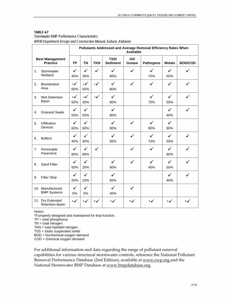
SECTION 4. STORMWATER QUALITY, EROSION, AND SEDIMENT CONTROL
4-116
TABLE 4-7 Stormwater BMP Performance Characteristics WRM Department Design and Construction Manual, Auburn, Alabama
Best Management Practice
Pollutants Addressed and Average Removal Efficiency Rates When Available
TP TN TKN TSS/
Sediment Oil/
Grease Pathogens Metals BOD/COD
1. Stormwater Wetland
40%
30%
80%
70%
50%
2. Bioretention Area
* 60%
* 50%
* 80%
3. Wet Detention Basin
* 50%
* 30%
* 80%
70%
50%
4. Grassed Swale 50%
50%
80%
40%
5. Infiltration Devices
60%
60%
80%
90%
90%
6. Buffers 40%
30%
85%
70%
50%
7. Permeable Pavement
80%
80%
90%
8. Sand Filter 50%
25%
80%
40%
50%
9. Filter Strip 20%
20%
50%
40%
10. Manufactured BMP Systems
5%
5%
40%
11. Dry Extended Retention Basin
* * * * * * * *
Notes: *If properly designed and maintained for that function. TP = total phosphorus TN = total nitrogen TKN = total Kjeldahl nitrogen TSS = totals suspended solids BOD = biochemical oxygen demand COD = chemical oxygen demand
For additional information and data regarding the range of pollutant removal capabilities for various structural stormwater controls, reference the National Pollutant Removal Performance Database (2nd Edition), available at www.cwp.org and the National Stormwater BMP Database at www.bmpdatabase.org.
SECTION 4. STORMWATER QUALITY, EROSION, AND SEDIMENT CONTROL
4-117
4.6 Structural Stormwater Control Selection 4.6.1 General Application Control Screening Process This process is intended to assist the site designer and design engineer in the selection of the most appropriate structural controls for a development site and to provide guidance regarding factors to consider in their location.
In general, the following criteria should be evaluated to select the appropriate structural control(s) or group of controls for a development:
• General suitability • Stormwater management suitability • Hot spot application • Flow attenuation efficiency • Costs • Monitoring and maintenance requirements • Key advantages and disadvantages
In addition, the following site-specific factors should be considered to determine any design criteria or restrictions that need to be evaluated:
• Physiographic factors • Soils • Special watershed or stream considerations
Finally, environmental regulations that may influence the location of a structural control onsite, or that may require a permit, need to be considered.
The following text describes a selection process for comparing and evaluating various general application structural stormwater controls using two screening matrixes and a list of location and permitting factors. These tools are provided to assist the design engineer in selecting the subset of structural controls that will meet the stormwater management and design objectives for a development site or project.
4.6.1.1 Step 1–Applicability Through the use of the first matrix (Table 4-8), the site designer evaluates and screens the overall applicability of the full set of general application structural controls, as well as the constraints of the site in question. The following are details regarding the various screening categories and individual characteristics used to evaluate the structural controls.
General Suitability. The first columns of the BMP Selection Matrix define the capability of each structural control to provide protection and treatment under three different development levels–Residential Subdivision, High Density/Ultra Urban Areas, and Regional Stormwater Controls. This classification provides an overview of the specific site conditions or criteria that must be met for a particular structural control to be suitable. A check mark indicates that the control is suitable to meet the listed criteria. A blank entry means that

SECTION 4. STORMWATER QUALITY, EROSION, AND SEDIMENT CONTROL
4-118
the structural control typically is not used for a specific site condition. This does not necessarily mean that the control should be eliminated from consideration, but rather is a reminder that more than one structural control may be needed at a site:
• Residential Subdivision Use. This column identifies whether a structural control is suitable for typical residential subdivision development (not including high-density or ultra-urban areas).
• High-Density/Ultra-Urban Areas. This column identifies those structural controls that are appropriate for use in high-density (ultra-urban) areas or areas in which space is at a premium.
• Regional Stormwater Controls. This column identifies those structural controls that are appropriate for large areas, not necessarily highly populated or developed. Regional controls are designed and installed strategically to provide stormwater controls in a subwatershed rather than in small onsite controls. These structures will manage stormwater runoff from multiple projects, and individual properties may reduce or eliminate onsite controls.

4-119
TABLE 4-8 BMP Selection Matrix WRM Department Design and Construction Manual, Auburn, Alabama
Best Management
Practice
General Suitability Stormwater Management Suitability
Hot spot Application
Flow Attenuation Efficiency Costs
Monitoring and
Maintenance Requirements
Key Advantages Key Disadvantages Residential Subdivision
High Density/Ultra Urban Areas
Regional Stormwater
Control Water
Quality Channel
Protection
Overbank Flood
Protection
Extreme Flood
Protection L M H L M H L M H
1. Stormwater Wetland
• Removes multiple pollutants. Attenuation of peak flows. Creation of wildlife habitat.
• Requires more land than other BMPs. Must maintain to control invasive species. Can attract waterfowl, which may increase pathogen levels.
2. Bioretention Area
• Removes multiple pollutants. Effective for reducing peak flow rates. May be used in small areas and integrated into existing or planned landscaping. Primary regular maintenance is basically landscaping and litter control.
• Requires regular maintenance including care for plants and replacement of mulch. May require frequent trash removal. Surface soil layer may clog over time, but can be replaced.
3. Wet Detention Basin
• Attenuation of peak flows. Perceived as ponds or lakes that enhance property value. Creates wildlife habitat. Appropriate in areas where infiltration is impractical.
• If not maintained, storm flows may resuspend sediments. Can become an eyesore and a nuisance if not maintained. Can attract waterfowl, which may increase pathogen levels. Not appropriate for areas with sensitive aquatic species due to potential thermal warming.
4. Grassed Swale
• Attenuation of peak flows. Inexpensive to construct and maintain. Can provide wildlife habitat.
• Standing water may provide habitat for mosquitoes. May channelize with concentrated flows. May pose traffic hazards if not properly designed.
5. Infiltration Devices
• Reduces frequency of flooding. Helps maintain shallow groundwater. Economical for small drainage areas.
• Can fail quickly compared to other types of BMPs. May clog easily and require pretreatment BMPs. Restricted to areas with permeable soils, deep water tables, and deep bedrock. Requires significant maintenance. Infiltration of stormwater has potential to contaminate groundwater.

4-120
TABLE 4-8 BMP Selection Matrix WRM Department Design and Construction Manual, Auburn, Alabama
Best Management
Practice
General Suitability Stormwater Management Suitability
Hot spot Application
Flow Attenuation Efficiency Costs
Monitoring and
Maintenance Requirements
Key Advantages Key Disadvantages Residential Subdivision
High Density/Ultra Urban Areas
Regional Stormwater
Control Water
Quality Channel
Protection
Overbank Flood
Protection
Extreme Flood
Protection L M H L M H L M H
6. Buffers
• Aesthetic and passive recreational benefits. Provides water quality treatment, erosion control, and water temperature benefits. Co-located trails can build support for greenways of riparian forest. Very inexpensive to construct.
• Sometimes seen as dangerous or unkempt public areas. Bank-side vegetation can be perceived as interfering with views of streams. Can be abused as places for illegal dumping. Often limited effectiveness due to concentration and piping of flows in watershed.
7. Permeable Pavement
• Reduces stormwater runoff rate and volume. Reduces pollutant load by reducing runoff volume. Potential component of LID site designs.
• Potential for clogging of porous media by sediment. High maintenance requirements. Limited to areas with sufficient drainage. Higher cost than conventional pavements. Not applicable for high-traffic areas or for use by heavy vehicles. Must have a slope less than 0.5%.
8. Sand Filter
• Highly effective at filtering TSS. Can filter flows from moderate to large areas. Larger units can attenuate runoff peaks, Useful where space is limited.
• Needs to integrate trash screens or grated inlets. If anoxic conditions develop, phosphorus levels can increase. May not be effective at controlling peak discharges. Can be unattractive without grass cover, or if trash accumulates on surface.
Notes: L = Low M = Moderate H = High

4-121
Stormwater Management Suitability. The second set of criteria in Table 4-8 examines the capability of each structural control option to provide water quality treatment, downstream channel protection, overbank flood protection, and extreme flood protection. A blank entry means that the structural control cannot be or typically is not used to meet a unified stormwater sizing criterion. This does not necessarily mean that it should be eliminated from consideration, but rather is a reminder that more than one structural control may be needed at a site (for example, a bioretention area used in conjunction with dry detention storage):
• Ability to treat the WQv. This indicates whether a structural control provides treatment of the WQv.
• Ability to provide Qp25. This indicates whether a structural control can be used to meet the Qp25 criteria. The presence of a check mark indicates that the structural control can be used to provide peak reduction of the 25-year storm event.
• Ability to provide extreme flood protection (Qf). This indicates whether a structural control can be used to meet the extreme flood protection criteria. The presence of a check mark indicates that the structural control can be used to provide peak reduction of the Qf.
Hot Spot Application. This column indicates the capability of a structural control to treat runoff from designated hot spots. Hot spots are land uses or activities that have higher potential pollutant loadings. Examples of hot spots might include gas stations, convenience stores, marinas, public works storage areas, vehicle service and maintenance areas, commercial nurseries, and auto recycling facilities. A check mark indicates that the structural control may be used on a hot spot; however, it may have specific design restrictions. Please see the specific design criteria of the structural control for more details.
Flow Attenuation Efficiency. This column generally describes the effectiveness of the particular BMP to control stormwater flow, especially the peaks that are expected as a result of the increase in impervious surfaces. This parameter is directly related to the ability of the BMP to provide channel protection.
Costs. This column establishes a cost comparison among the recommended BMPs. Actual construction costs and maintenance costs will vary depending on a number of factors, including the size and location of the control, the pollutant loading to the control from the upstream watershed, and the type of maintenance that needs to be performed. Differences in construction costs also may be affected by the availability of land and other site-specific constraints.
Monitoring and Maintenance Requirements. This column provides information regarding the relative monitoring and maintenance requirements for each BMP to work effectively and to comply with stormwater regulations. This information is useful and important because it may drive the O&M costs.
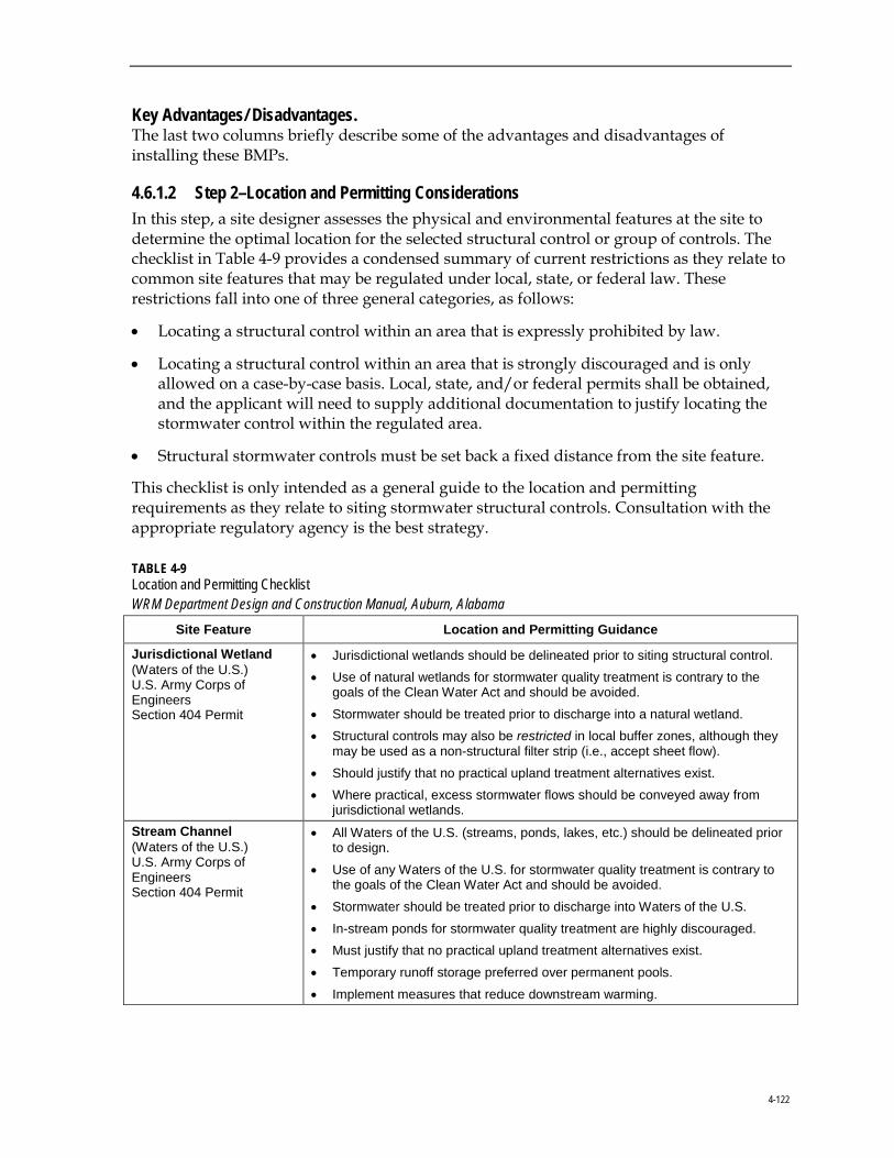
4-122
Key Advantages/ Disadvantages. The last two columns briefly describe some of the advantages and disadvantages of installing these BMPs.
4.6.1.2 Step 2–Location and Permitting Considerations In this step, a site designer assesses the physical and environmental features at the site to determine the optimal location for the selected structural control or group of controls. The checklist in Table 4-9 provides a condensed summary of current restrictions as they relate to common site features that may be regulated under local, state, or federal law. These restrictions fall into one of three general categories, as follows:
• Locating a structural control within an area that is expressly prohibited by law.
• Locating a structural control within an area that is strongly discouraged and is only allowed on a case-by-case basis. Local, state, and/or federal permits shall be obtained, and the applicant will need to supply additional documentation to justify locating the stormwater control within the regulated area.
• Structural stormwater controls must be set back a fixed distance from the site feature.
This checklist is only intended as a general guide to the location and permitting requirements as they relate to siting stormwater structural controls. Consultation with the appropriate regulatory agency is the best strategy.
TABLE 4-9 Location and Permitting Checklist WRM Department Design and Construction Manual, Auburn, Alabama
Site Feature Location and Permitting Guidance
Jurisdictional Wetland (Waters of the U.S.) U.S. Army Corps of Engineers Section 404 Permit
• Jurisdictional wetlands should be delineated prior to siting structural control. • Use of natural wetlands for stormwater quality treatment is contrary to the
goals of the Clean Water Act and should be avoided.
• Stormwater should be treated prior to discharge into a natural wetland. • Structural controls may also be restricted in local buffer zones, although they
may be used as a non-structural filter strip (i.e., accept sheet flow).
• Should justify that no practical upland treatment alternatives exist. • Where practical, excess stormwater flows should be conveyed away from
jurisdictional wetlands. Stream Channel (Waters of the U.S.) U.S. Army Corps of Engineers Section 404 Permit
• All Waters of the U.S. (streams, ponds, lakes, etc.) should be delineated prior to design.
• Use of any Waters of the U.S. for stormwater quality treatment is contrary to the goals of the Clean Water Act and should be avoided.
• Stormwater should be treated prior to discharge into Waters of the U.S.
• In-stream ponds for stormwater quality treatment are highly discouraged. • Must justify that no practical upland treatment alternatives exist.
• Temporary runoff storage preferred over permanent pools.
• Implement measures that reduce downstream warming.
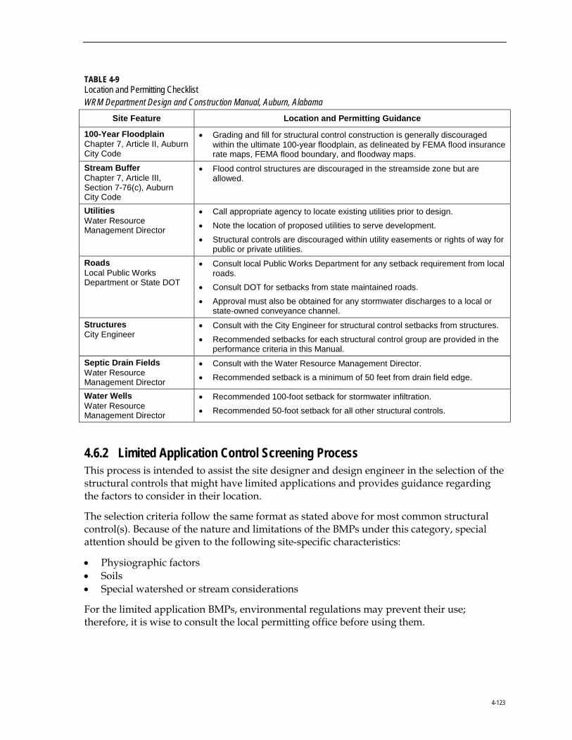
4-123
TABLE 4-9 Location and Permitting Checklist WRM Department Design and Construction Manual, Auburn, Alabama
Site Feature Location and Permitting Guidance
100-Year Floodplain Chapter 7, Article II, Auburn City Code
• Grading and fill for structural control construction is generally discouraged within the ultimate 100-year floodplain, as delineated by FEMA flood insurance rate maps, FEMA flood boundary, and floodway maps.
Stream Buffer Chapter 7, Article III, Section 7-76(c), Auburn City Code
• Flood control structures are discouraged in the streamside zone but are allowed.
Utilities Water Resource Management Director
• Call appropriate agency to locate existing utilities prior to design.
• Note the location of proposed utilities to serve development.
• Structural controls are discouraged within utility easements or rights of way for public or private utilities.
Roads Local Public Works Department or State DOT
• Consult local Public Works Department for any setback requirement from local roads.
• Consult DOT for setbacks from state maintained roads.
• Approval must also be obtained for any stormwater discharges to a local or state-owned conveyance channel.
Structures City Engineer
• Consult with the City Engineer for structural control setbacks from structures.
• Recommended setbacks for each structural control group are provided in the performance criteria in this Manual.
Septic Drain Fields Water Resource Management Director
• Consult with the Water Resource Management Director. • Recommended setback is a minimum of 50 feet from drain field edge.
Water Wells Water Resource Management Director
• Recommended 100-foot setback for stormwater infiltration.
• Recommended 50-foot setback for all other structural controls.
4.6.2 Limited Application Control Screening Process This process is intended to assist the site designer and design engineer in the selection of the structural controls that might have limited applications and provides guidance regarding the factors to consider in their location.
The selection criteria follow the same format as stated above for most common structural control(s). Because of the nature and limitations of the BMPs under this category, special attention should be given to the following site-specific characteristics:
• Physiographic factors • Soils • Special watershed or stream considerations
For the limited application BMPs, environmental regulations may prevent their use; therefore, it is wise to consult the local permitting office before using them.
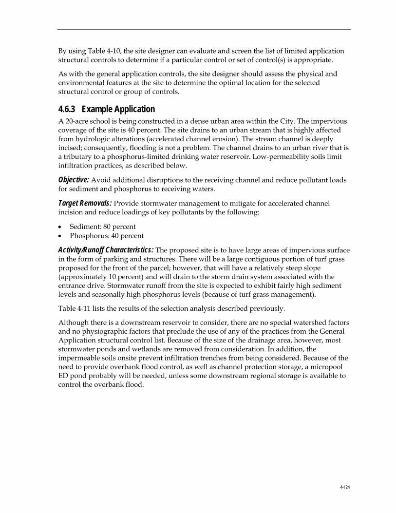
4-124
By using Table 4-10, the site designer can evaluate and screen the list of limited application structural controls to determine if a particular control or set of control(s) is appropriate.
As with the general application controls, the site designer should assess the physical and environmental features at the site to determine the optimal location for the selected structural control or group of controls.
4.6.3 Example Application A 20-acre school is being constructed in a dense urban area within the City. The impervious coverage of the site is 40 percent. The site drains to an urban stream that is highly affected from hydrologic alterations (accelerated channel erosion). The stream channel is deeply incised; consequently, flooding is not a problem. The channel drains to an urban river that is a tributary to a phosphorus-limited drinking water reservoir. Low-permeability soils limit infiltration practices, as described below.
Objective: Avoid additional disruptions to the receiving channel and reduce pollutant loads for sediment and phosphorus to receiving waters.
Target Removals: Provide stormwater management to mitigate for accelerated channel incision and reduce loadings of key pollutants by the following:
• Sediment: 80 percent • Phosphorus: 40 percent
Activity/Runoff Characteristics: The proposed site is to have large areas of impervious surface in the form of parking and structures. There will be a large contiguous portion of turf grass proposed for the front of the parcel; however, that will have a relatively steep slope (approximately 10 percent) and will drain to the storm drain system associated with the entrance drive. Stormwater runoff from the site is expected to exhibit fairly high sediment levels and seasonally high phosphorus levels (because of turf grass management).
Table 4-11 lists the results of the selection analysis described previously.
Although there is a downstream reservoir to consider, there are no special watershed factors and no physiographic factors that preclude the use of any of the practices from the General Application structural control list. Because of the size of the drainage area, however, most stormwater ponds and wetlands are removed from consideration. In addition, the impermeable soils onsite prevent infiltration trenches from being considered. Because of the need to provide overbank flood control, as well as channel protection storage, a micropool ED pond probably will be needed, unless some downstream regional storage is available to control the overbank flood.
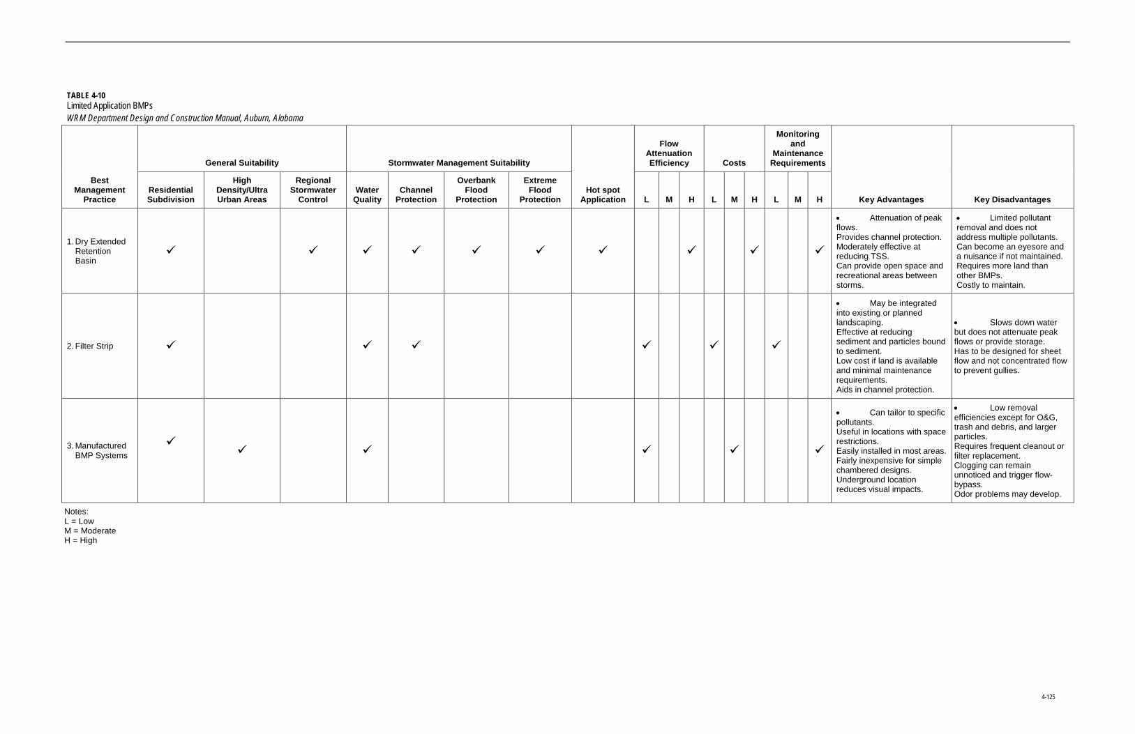
4-125
TABLE 4-10 Limited Application BMPs WRM Department Design and Construction Manual, Auburn, Alabama
Best Management
Practice
General Suitability Stormwater Management Suitability
Hot spot Application
Flow Attenuation Efficiency Costs
Monitoring and
Maintenance Requirements
Key Advantages Key Disadvantages Residential Subdivision
High Density/Ultra Urban Areas
Regional Stormwater
Control Water
Quality Channel
Protection
Overbank Flood
Protection
Extreme Flood
Protection L M H L M H L M H
1. Dry Extended Retention Basin
• Attenuation of peak flows. Provides channel protection. Moderately effective at reducing TSS. Can provide open space and recreational areas between storms.
• Limited pollutant removal and does not address multiple pollutants. Can become an eyesore and a nuisance if not maintained. Requires more land than other BMPs. Costly to maintain.
2. Filter Strip
• May be integrated into existing or planned landscaping. Effective at reducing sediment and particles bound to sediment. Low cost if land is available and minimal maintenance requirements. Aids in channel protection.
• Slows down water but does not attenuate peak flows or provide storage. Has to be designed for sheet flow and not concentrated flow to prevent gullies.
3. Manufactured BMP Systems
• Can tailor to specific pollutants. Useful in locations with space restrictions. Easily installed in most areas. Fairly inexpensive for simple chambered designs. Underground location reduces visual impacts.
• Low removal efficiencies except for O&G, trash and debris, and larger particles. Requires frequent cleanout or filter replacement. Clogging can remain unnoticed and trigger flow-bypass. Odor problems may develop.
Notes: L = Low M = Moderate H = High

4-126
TABLE 4-11 Sample Structural Control Selection Matrix WRM Department Design and Construction Manual, Auburn, Alabama
General Application Structural
Control General
Suitability
Stormwater Management
Suitability Hot spot
Flow Attenuation Efficiency Costs
Monitoring and
Maintenance Requirements
Other Issues
Wet Pond X
Wet ED Ponds X
Micropool ED Ponds X
Multiple Ponds X
Shallow Wetland X
ED Shallow Wetland X
Pocket Wetland
Odor/ mosquitoes
Infiltration Trench 1 X X X
Surface Sand Filter 1 2 X aesthetics
Perimeter SF 1 2 X Cost
Bioretention 1 2 X
Dry Swale 1 2 X X X
Wet Swale 1 2 X X X Odor/
mosquitoes
Notes: 1Only when used with another structural control that provides water quality control 2Can treat a portion of the site
To provide additional pollutant removal capabilities in an attempt to better meet the target removals, bioretention, surface sand filters, and/or perimeter sand filters can be used to treat the parking lot and driveway runoff. The bioretention provides some removal of phosphorus while improving the aesthetics of the site. Surface sand filters provide higher phosphorus removal at a comparable unit cost to bioretention, but are not as aesthetically pleasing. The perimeter sand filter is a flexible, easy-to-access practice (but at higher cost) that provides good phosphorus removal and additionally high O&G trapping ability.

4-127
The site drainage system can be designed so that the bioretention and/or sand filters drain to the micropool ED pond for redundant treatment. Vegetated dry swales also could be used to convey runoff to the pond, which would provide pretreatment. Pocket wetlands and wet swales were eliminated from consideration because of the potential for nuisance conditions. Underground sand filters also could be used at the site; however, the cost and aesthetic considerations were significant enough to eliminate these from consideration.
4.6.4 Online Versus Offline Structural Controls Structural stormwater controls are designed to be either “online” or “offline.” Online facilities are designed to receive, but not necessarily control or treat, the entire runoff volume up to the Qp25 or Qf event. Online structural controls must be able to handle the entire range of storm flows.
Offline facilities, on the other hand, are designed to receive only a specified flow rate through the use of a flow regulator (i.e., diversion structure, flow splitter, etc.). Flow regulators typically are used to divert the WQv to an offline structural control that is sized and designed to treat and control the WQv. After the design runoff flow has been treated and/or controlled, it is returned to the conveyance system. Figure 4-30 shows examples of an offline sand filter and an offline enhanced dry swale.
FIGURE 4-30
Example of Online versus Offline Structural Controls Source: CWP (1996)
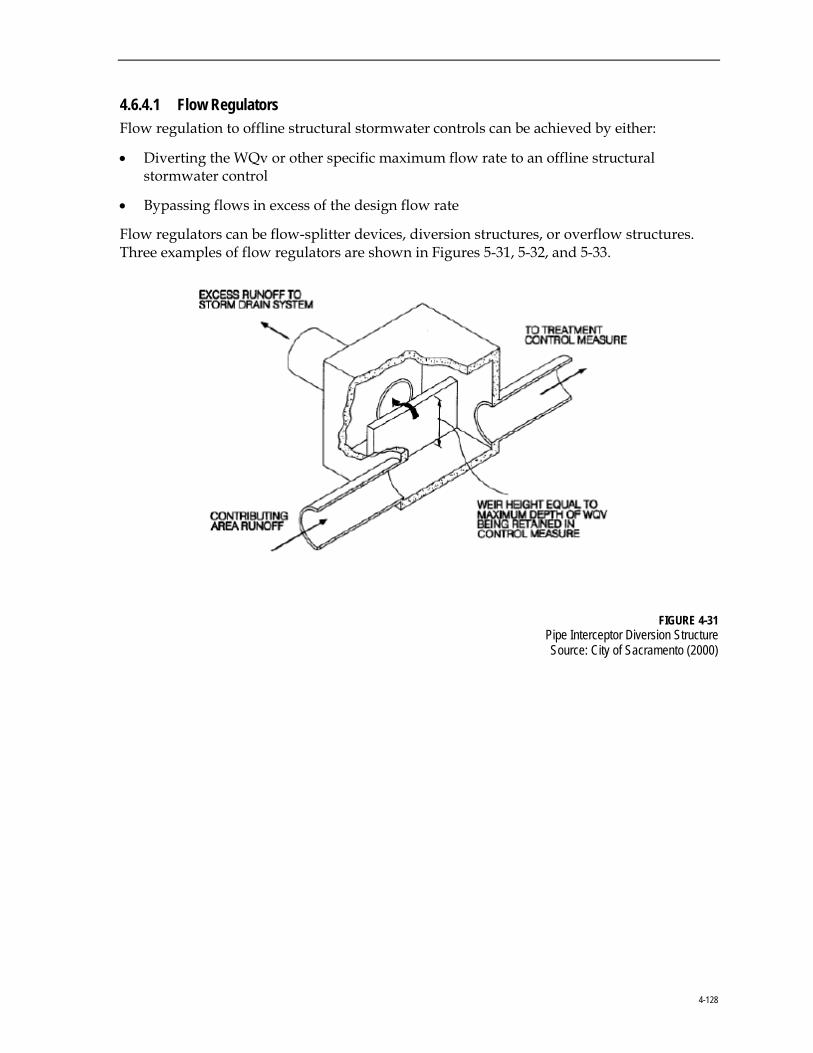
4-128
4.6.4.1 Flow Regulators Flow regulation to offline structural stormwater controls can be achieved by either:
• Diverting the WQv or other specific maximum flow rate to an offline structural stormwater control
• Bypassing flows in excess of the design flow rate
Flow regulators can be flow-splitter devices, diversion structures, or overflow structures. Three examples of flow regulators are shown in Figures 5-31, 5-32, and 5-33.
FIGURE 4-31 Pipe Interceptor Diversion Structure Source: City of Sacramento (2000)
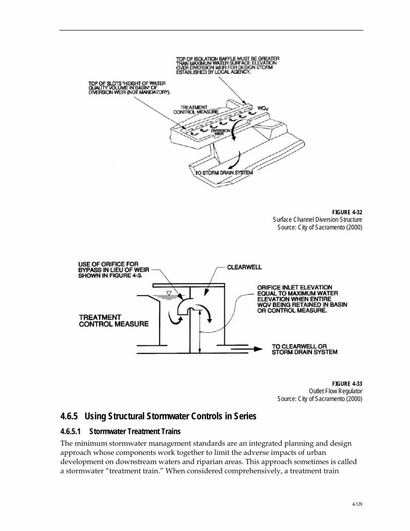
4-129
FIGURE 4-32 Surface Channel Diversion Structure
Source: City of Sacramento (2000)
FIGURE 4-33
Outlet Flow Regulator Source: City of Sacramento (2000)
4.6.5 Using Structural Stormwater Controls in Series 4.6.5.1 Stormwater Treatment Trains The minimum stormwater management standards are an integrated planning and design approach whose components work together to limit the adverse impacts of urban development on downstream waters and riparian areas. This approach sometimes is called a stormwater “treatment train.” When considered comprehensively, a treatment train
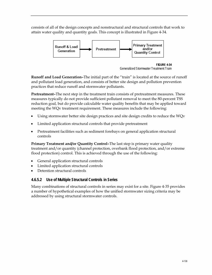
4-130
consists of all of the design concepts and nonstructural and structural controls that work to attain water quality and quantity goals. This concept is illustrated in Figure 4-34.
FIGURE 4-34
Generalized Stormwater Treatment Train
Runoff and Load Generation–The initial part of the “train” is located at the source of runoff and pollutant load generation, and consists of better site design and pollution prevention practices that reduce runoff and stormwater pollutants.
Pretreatment–The next step in the treatment train consists of pretreatment measures. These measures typically do not provide sufficient pollutant removal to meet the 80-percent TSS reduction goal, but do provide calculable water quality benefits that may be applied toward meeting the WQv treatment requirement. These measures include the following:
• Using stormwater better site design practices and site design credits to reduce the WQv
• Limited application structural controls that provide pretreatment
• Pretreatment facilities such as sediment forebays on general application structural controls
Primary Treatment and/or Quantity Control–The last step is primary water quality treatment and/or quantity (channel protection, overbank flood protection, and/or extreme flood protection) control. This is achieved through the use of the following:
• General application structural controls • Limited application structural controls • Detention structural controls
4.6.5.2 Use of Multiple Structural Controls in Series Many combinations of structural controls in series may exist for a site. Figure 4-35 provides a number of hypothetical examples of how the unified stormwater sizing criteria may be addressed by using structural stormwater controls.

4-131
FIGURE 4-35 Examples of Structural Controls Used in Series
Referring to Figure 4-35 by line letter:
A. Two general application (GA) structural controls–stormwater ponds and stormwater wetlands–can be used to meet all of the unified stormwater sizing criteria in a single facility.
B. The other general application structural controls (bioretention, sand filters, infiltration trench, and enhanced swale) typically are used in combination with detention controls to meet the unified stormwater sizing criteria. The detention facilities are located downstream from the water quality controls either onsite or combined into a regional or neighborhood facility.
C. Line C indicates the condition where an environmentally sensitive large lot subdivision has been developed that can be designed to waive the water quality treatment requirement altogether. Detention controls may still be required, however, for downstream channel protection, overbank flood protection, and extreme flood protection.
D. Where a limited application (LA) structural control does not meet the 80-percent TSS removal criteria, another downstream structural control must be added. For example, urban hot spot land may be fit or retrofit with devices adjacent to parking or service areas designed to remove petroleum hydrocarbons. These devices also may serve as pretreatment devices by removing the coarser fraction of sediment. One or more downstream structural controls is then used to meet the full 80-percent TSS removal goal, as well as the water quantity control.
E. In line E, site design credits have been used to partially reduce the WQv requirement. In this case, for a smaller site, a well-designed and tested LA structural control provides
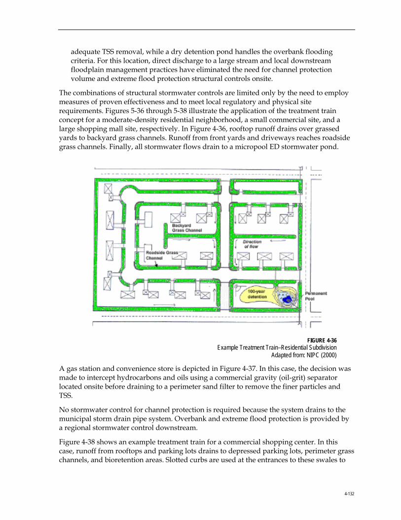
4-132
adequate TSS removal, while a dry detention pond handles the overbank flooding criteria. For this location, direct discharge to a large stream and local downstream floodplain management practices have eliminated the need for channel protection volume and extreme flood protection structural controls onsite.
The combinations of structural stormwater controls are limited only by the need to employ measures of proven effectiveness and to meet local regulatory and physical site requirements. Figures 5-36 through 5-38 illustrate the application of the treatment train concept for a moderate-density residential neighborhood, a small commercial site, and a large shopping mall site, respectively. In Figure 4-36, rooftop runoff drains over grassed yards to backyard grass channels. Runoff from front yards and driveways reaches roadside grass channels. Finally, all stormwater flows drain to a micropool ED stormwater pond.
FIGURE 4-36
Example Treatment Train–Residential Subdivision Adapted from: NIPC (2000)
A gas station and convenience store is depicted in Figure 4-37. In this case, the decision was made to intercept hydrocarbons and oils using a commercial gravity (oil-grit) separator located onsite before draining to a perimeter sand filter to remove the finer particles and TSS.
No stormwater control for channel protection is required because the system drains to the municipal storm drain pipe system. Overbank and extreme flood protection is provided by a regional stormwater control downstream.
Figure 4-38 shows an example treatment train for a commercial shopping center. In this case, runoff from rooftops and parking lots drains to depressed parking lots, perimeter grass channels, and bioretention areas. Slotted curbs are used at the entrances to these swales to
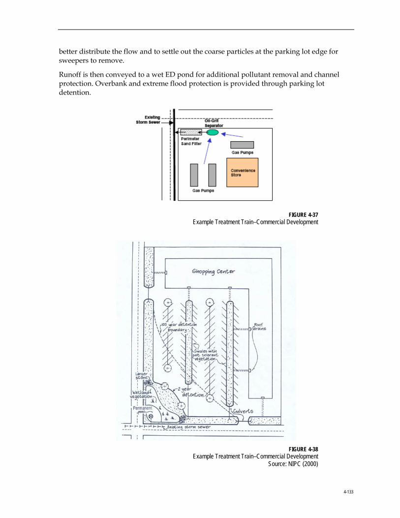
4-133
better distribute the flow and to settle out the coarse particles at the parking lot edge for sweepers to remove.
Runoff is then conveyed to a wet ED pond for additional pollutant removal and channel protection. Overbank and extreme flood protection is provided through parking lot detention.
FIGURE 4-37
Example Treatment Train–Commercial Development
FIGURE 4-38
Example Treatment Train–Commercial Development Source: NIPC (2000)

4-134
4.6.5.3 Calculation of Pollutant Removal for Structural Controls in Series For two or more structural stormwater controls used in combination, it is often important to have an estimate of the pollutant-removal efficiency of the treatment train. Pollutant-removal rates for structural controls in series are not additive. For pollutants in particulate form, the actual removal rate (expressed in terms of percentage of pollution removed) varies directly with the pollution concentration and sediment size distribution of runoff entering a facility.
For example, a stormwater pond facility will have a much higher pollutant-removal percentage for turbid runoff than for clearer water. When two stormwater ponds are placed in series, the second pond will treat an incoming particulate pollutant load differently from the first pond. The upstream pond captures the easily removed larger sediment sizes, passing on an outflow with a lower concentration of TSS, but with a higher proportion of finer particle sizes. Hence, the removal capability of the second pond for TSS is considerably less than that of the first pond. Recent findings suggest that the second pond in series can provide as little as half the removal efficiency of the upstream pond.
To estimate the pollutant-removal rate of structural controls in series, a method is used in which the removal efficiency of a downstream structural control is reduced to account for the pollutant removal of the upstream control(s). The following steps are used to determine the pollutant removal:
• For each drainage area, list the structural controls in order, upstream to downstream, along with their expected average pollutant-removal rates from Table 4-7 for the pollutants of concern.
• For any GA structural control located downstream from another GA control or an LA structural control that has TSS removal rates equivalent to 80 percent, the designer should use 50 percent of the normal pollutant-removal rate for the second control in series. For a GA structural control located downstream from an LA structural control that cannot achieve the 80-percent TSS reduction goal, the designer should use 75 percent of the normal pollutant removal rate for the second control in series.
• For example, if a GA structural control has an 80-percent TSS-removal rate, then a 40-percent TSS-removal rate would be assumed for this control if it were placed downstream from another GA control in the treatment train (0.5 x 80 percent). If it were placed downstream from an LA structural control that cannot achieve the 80-percent TSS-reduction goal, a 60-percent TSS-removal rate would be assumed (0.75 x 80 percent). Use this rule with caution depending on the actual pollutant of concern and make allowances for differences among structural control pollutant removal rates for different pollutants. Actual data from similar situations, where available, should be used to temper or override this rule of thumb.
• For cases where an LA control is sited upstream from a GA control in the treatment train, the downstream GA structural control is given full credit for the removal of pollutants.

4-135
• Apply the following equation to calculate approximate total accumulated pollution removal for controls in series:
Final Pollutant Removal = (Total load * Control1 removal rate) + (Remaining load * Control2 removal rate) + … for other Controls in series.
Example. TSS is the pollutant of concern and a commercial device is inserted that has a 20-percent sediment-removal rate. A stormwater pond is designed at the site outlet. A second stormwater pond is located downstream from the first one in series. What is the total TSS-removal rate? The following information is given:
Control 1 (Commercial Device) = 20% TSS removal
Control 2 (Stormwater Pond 1) = 80% TSS removal (use 1.0 x design removal rate)
Control 3 (Stormwater Pond 2) = 40% TSS removal (use 0.5 x design removal rate)
By applying the controls in order and working in terms of “units” of TSS starting at 100 units:
For Control 1: 100 units of TSS * 20% removal rate = 20 units removed
100 units – 20 units removed = 80 units of TSS remaining
For Control 2: 80 units of TSS * 80% removal rate = 64 units removed
80 units – 64 units removed = 16 units of TSS remaining
For Control 3: 16 units of TSS * 40% removal rate = 6 units removed
16 units – 6 units removed = 10 units TSS remaining
For the treatment train in total = 100 units TSS – 10 units TSS remaining = 90% removal
4.6.5.4 Routing with WQv Removed When offline structural controls such as bioretention areas, sand filters, and infiltration trenches capture and remove the WQv, downstream structural controls do not have to account for this volume during design. That is, the WQv may be subtracted from the total volume that otherwise would need to be routed through the downstream structural controls.
From a calculation standpoint, this would amount to removing the initial WQv from the beginning of the runoff hydrograph, thus creating a “notch” in the runoff hydrograph. Because most commercially available hydrologic modeling packages cannot handle this type of action, the following method has been created to facilitate removal from the runoff hydrograph of approximately the WQv:
• Enter the horizontal axis in Figure 4-39 with the impervious percentage of the watershed and read upward to the predominant soil type (interpolation between curves is permitted).

4-136
• Read left to the factor.
• Multiply the NC for the subwatershed that includes the water quality basin by this factor (this provides a smaller CN).
The difference in CN will generate a runoff hydrograph that has a volume less than the original volume by an amount approximately equal to the WQv. This method should be used only for bioretention areas, filter facilities, and infiltration trenches in cases where the drawdown time is ≥ 24 hours.
FIGURE 4-39
Curve Number Adjustment Factor
Example. A site design employs an infiltration trench for the WQv and has a CN of 72, is B Type soil, and has an impervious percentage of 70 percent; the factor from Figure 4-39 is 0.92. The CN to be used in calculation of a runoff hydrograph for the quantity controls would be: (72*0.92) = 66.

4-137
4.7 City of Auburn Site Development Review Tool The City's Site Development Review Tool was designed to assist engineers and developers in planning stormwater management features for proposed projects. Through the tool, users can make informed decisions regarding water quality protection and stormwater BMP design as a result of potential impacts from their developments.
The Site Development Review Tool was developed using a Microsoft® Excel format and can be used by engineers and developers to design and incorporate BMPs for City developments and to maximize the efficiency of runoff pollutant management following the construction of developments. The tool also can be used to meet the target pollutant removal efficiencies outlined in the City's Conservation Subdivision Regulations. This tool will provide pollutant removal estimates for site-specific conditions based on removal efficiencies for a variety of stormwater BMPs, including detention ponds, bioretention areas (rain gardens), and stormwater wetlands. The tool analyzes a variety of stormwater pollutants including nutrients (phosphorus and nitrogen) and TSS. City staff will use this tool during the plan review process to analyze development impacts on water quality within the Lake Ogletree watershed, as well as additional watersheds within the City. The Tool can be obtained from the City’s web site at: http://www.auburnalabama.org/wrm/sitedevelopment.asp. Instructions about how to use the tool are included on a tab within the spreadsheet.

4-138
4.8 City of Auburn Conservation Subdivision Regulations Article VI of the City’s Subdivision Regulations (Amended March 2008) lists the regulations for Conservation Subdivisions. A Conservation Subdivision, as defined in the zoning regulations, is:
A development design technique that concentrates buildings on a part of the site to allow the remaining land to be used for open space or preservation of environmentally sensitive areas. The open space may be owned by either a private or public entity.
Article VI applies to all divisions of land in the subdivision jurisdiction that lie within the Lake Ogletree Subwatershed that are 10 acres or more, and where the division creates more than four lots. In addition, the Conservation Subdivision regulations only apply to land within the corporate limits zoned as a Conservation Overlay District (COD) (for details, refer to the City’s Zoning Ordinance, Section 513, COD).
With respect to stormwater quality, Article VI requires stormwater BMPs if the impervious surface ratio (ISR), the ratio impervious surface to gross area, of the subdivision exceeds 10 percent (Article VI, Section G). A Stormwater Management Plan for the proposed project also is required for an ISR greater than 10 percent.
A copy of the Subdivision Regulations dated March 2008 can be obtained from the City’s web site at: http://www.auburnalabama.org/pl/Subdivision%20Regulations/03-18-08%20Amendments/Subdivision%20Regulations%20as%20Amended%20on%2003-18-08.pdf.

4-139
4.9 References Atlanta Regional Council. 2001. Georgia Stormwater Management Manual. Atlanta, Georgia.
Auburn. 2008. Official Code. City of Auburn, Alabama.
Auburn. 2008. Subdivision Regulations. City of Auburn, Alabama.
Caltrans. 2000. Erosion Control Pilot Study Report, June 2000.
CH2M HILL. 2003. City of Auburn Stormwater Management Manual. City of Auburn, Alabama.
Pitt, R. 1994. Small Storm Hydrology. University of Alabama–Birmingham. Unpublished manuscript. Presented at Design of Stormwater Quality Management Practices. Madison, Wisconsin. May 17 through May 19, 1994.
Schueler, T. 1987. Controlling Urban Runoff: A Practical Manual for Planning and Designing Urban BMPs. Metropolitan Washington Council of Governments.
Schueler, T. 1994. The Importance of Imperviousness. Watershed Protection Techniques 1(3): 100-111.
Schueler, T. 1995. Site Planning for Urban Stream Protection. Center for Watershed Protection, Ellicott City, Maryland.
Schueler, T. R., P. A. Kumble, and M. A. Heraty. 1992. A Current Assessment of Urban Best Management Practices–Techniques for Reducing Non-point Source Pollution in the Coastal Zone. Metropolitan Washington Council of Governments, Department of Environmental Programs, Anacostia Restoration Team, Washington, D.C.
U.S. Department of Agriculture (USDA). 1986. Urban Hydrology for Small Watersheds. Soil Conservation Service, Engineering Division. Technical Release 55 (TR-55).