Embed Size (px)
Citation preview
The Islamic University of GazaFaculty of Engineering
Civil Engineering Department
Sanitary Engineering(ECIV 4325)
Instructor: Dr. Abdelmajid NassarLect. W12-13
Secondary Wastewater Treatment
Treatment stages - Secondary treatment
• Degrade biological content (dissolved organic matter) of the sewage– Ex: human waste, food waste, soaps, detergent
• Added bacteria and protozoa into sewage
• 3 different approaches– Fixed film system
– Suspended film system
– Lagoon system
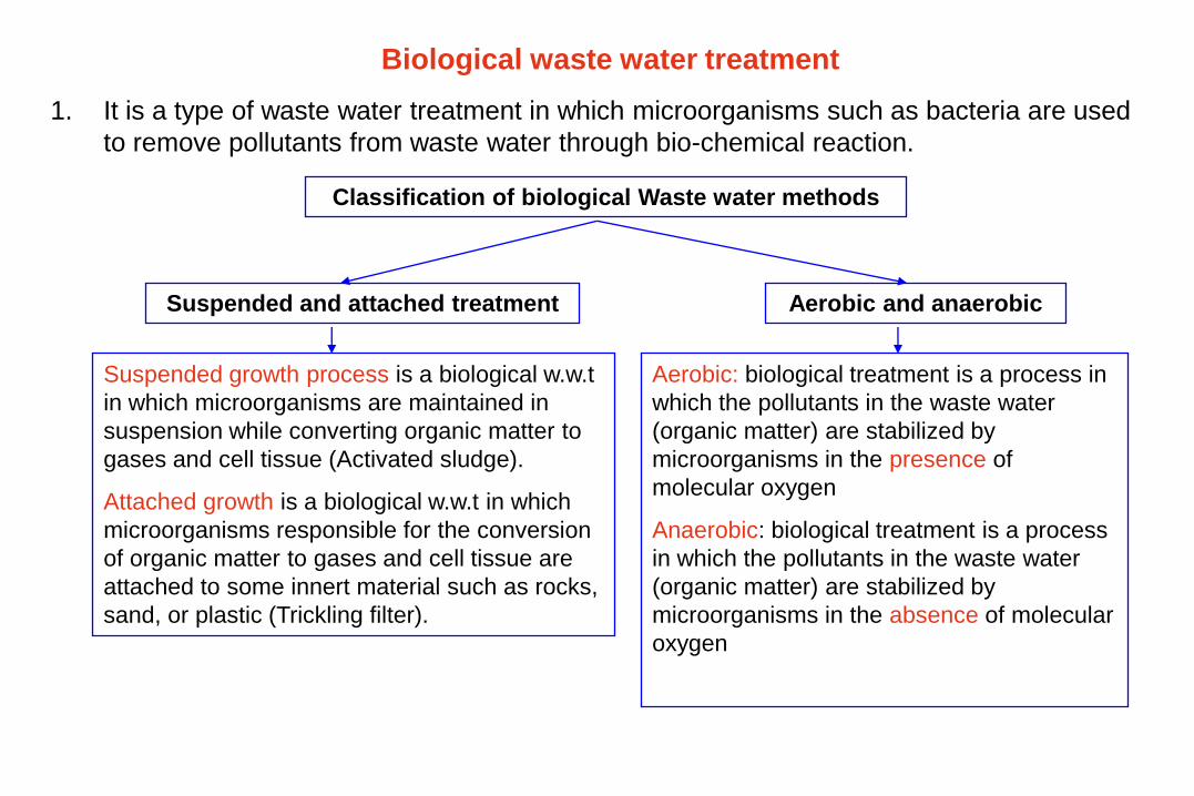
Biological waste water treatment
1. It is a type of waste water treatment in which microorganisms such as bacteria are used
to remove pollutants from waste water through bio-chemical reaction.
Classification of biological Waste water methods
Aerobic and anaerobicSuspended and attached treatment
Aerobic: biological treatment is a process in
which the pollutants in the waste water
(organic matter) are stabilized by
microorganisms in the presence of
molecular oxygen
Anaerobic: biological treatment is a process
in which the pollutants in the waste water
(organic matter) are stabilized by
microorganisms in the absence of molecular
oxygen
Suspended growth process is a biological w.w.t
in which microorganisms are maintained in
suspension while converting organic matter to
gases and cell tissue (Activated sludge).
Attached growth is a biological w.w.t in which
microorganisms responsible for the conversion
of organic matter to gases and cell tissue are
attached to some innert material such as rocks,
sand, or plastic (Trickling filter).
Activated Sludge System
Process Description:
• It is aerobic suspended growth biological wastewater treatment method in which dissolved
organic and inorganic matter can be removed. Some of the suspended and colloidal matter
can also be removed indirectly by sticking to the slime bacteria.
• This treatment is achieved in tanks called aeration tanks. Oxygen is supplied to these tanks
to allow aerobic biochemical reaction to occur.
• In the aeration tank, the microorganisms feed on dissolved solids mainly organic matter and
produce large amounts of bacteria (colonies). This means that microorganisms convert
dissolved solids into suspended solids (the bacterial colonies).
• After the aeration tank, a secondary sedimentation tank is installed to separate the bacteria
from liquid
• The separated bacteria is called activated sludge. Part of the sludge is wasted and the
remaining part is returned back (Recycle) to the aeration tank. The recycle of the sludge to
aeration tank is very important to keep a specific concentration of the bacteria in the system
to perform wastewater treatment.
• The mixture of wastewater with bacteria in the aeration tank is called mixed liquor
suspended solids (MLSS)
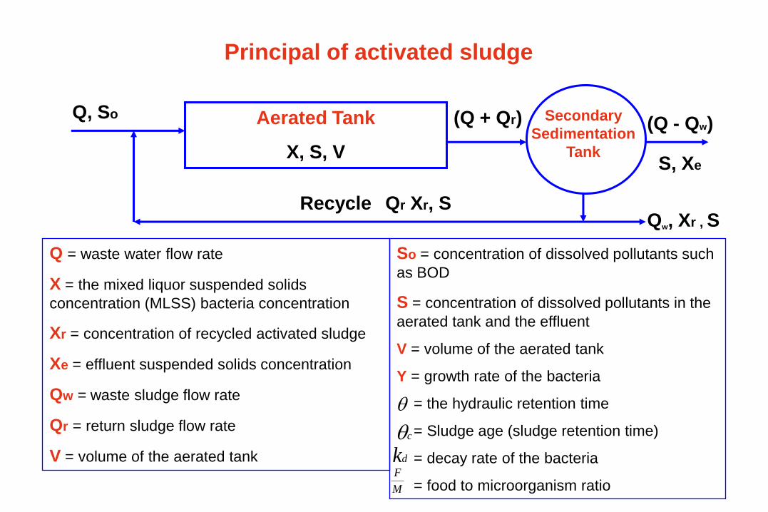
Principal of activated sludge
Aerated Tank
X, S, V
Q, So
Qr Xr, SRecycleQw, Xr , S
(Q + Qr) (Q - Qw)
S, Xe
Q = waste water flow rate
X = the mixed liquor suspended solids
concentration (MLSS) bacteria concentration
Xr = concentration of recycled activated sludge
Xe = effluent suspended solids concentration
Qw = waste sludge flow rate
Qr = return sludge flow rate
V = volume of the aerated tank
So = concentration of dissolved pollutants such
as BOD
S = concentration of dissolved pollutants in the
aerated tank and the effluent
V = volume of the aerated tank
Y = growth rate of the bacteria
= the hydraulic retention time
= Sludge age (sludge retention time)
= decay rate of the bacteria
= food to microorganism ratio
Secondary
Sedimentation
Tank
cdk
M
F
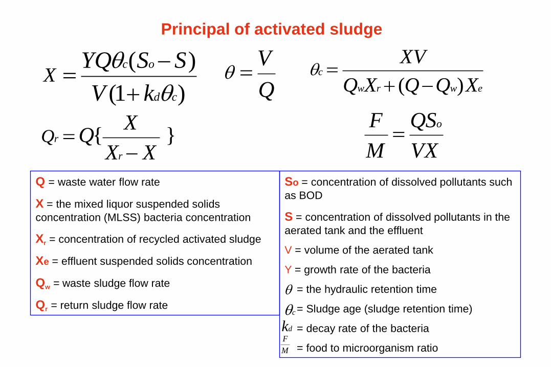
Principal of activated sludge
)1(
)(
cd
oc
kV
SSYQX
ewrw
c
XQQXQ
XV
)(
Q
V
}{XX
XQ
r
rQ
VX
QS
M
F o
Q = waste water flow rate
X = the mixed liquor suspended solids
concentration (MLSS) bacteria concentration
Xr = concentration of recycled activated sludge
Xe = effluent suspended solids concentration
Qw = waste sludge flow rate
Qr = return sludge flow rate
So = concentration of dissolved pollutants such
as BOD
S = concentration of dissolved pollutants in the
aerated tank and the effluent
V = volume of the aerated tank
Y = growth rate of the bacteria
= the hydraulic retention time
= Sludge age (sludge retention time)
= decay rate of the bacteria
= food to microorganism ratio
cdk
M
F
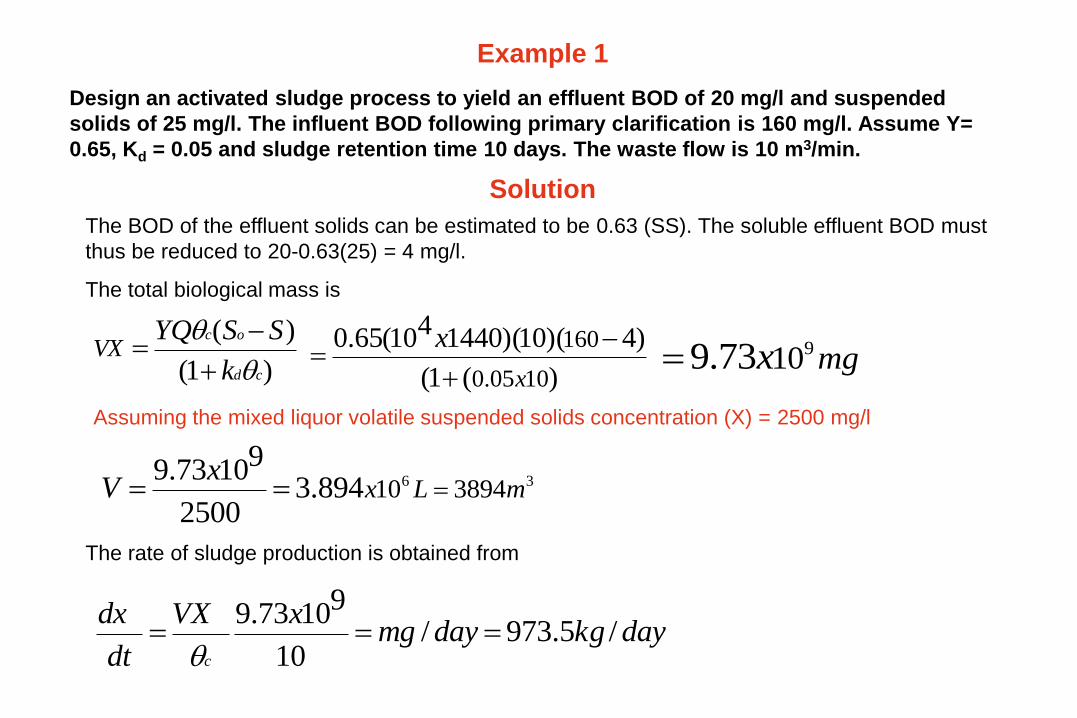
Example 1
Design an activated sludge process to yield an effluent BOD of 20 mg/l and suspended
solids of 25 mg/l. The influent BOD following primary clarification is 160 mg/l. Assume Y=
0.65, Kd = 0.05 and sludge retention time 10 days. The waste flow is 10 m3/min.
Solution
The BOD of the effluent solids can be estimated to be 0.63 (SS). The soluble effluent BOD must
thus be reduced to 20-0.63(25) = 4 mg/l.
The total biological mass is
)1(
)(
cd
oc
k
SSYQVX
)(1(
)4)(10)(1440410(65.0
1005.0
160
x
x
mgx 91073.9
36 389410894.32500
91073.9mLx
xV
Assuming the mixed liquor volatile suspended solids concentration (X) = 2500 mg/l
The rate of sludge production is obtained from
daykgdaymgxVX
dt
dx
c
/5.973/10
91073.9
daymlmgx
daymgxQw /31.81
/31015
/6101217
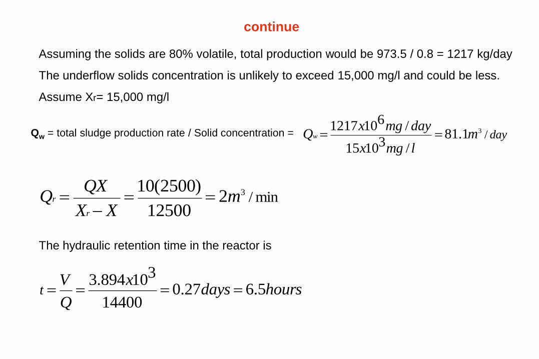
min/3212500
)2500(10m
XX
QXQ
r
r
Assuming the solids are 80% volatile, total production would be 973.5 / 0.8 = 1217 kg/day
The underflow solids concentration is unlikely to exceed 15,000 mg/l and could be less.
Assume Xr= 15,000 mg/l
hoursdaysx
Q
Vt 5.627.0
14400
310894.3
The hydraulic retention time in the reactor is
continue
Qw = total sludge production rate / Solid concentration =
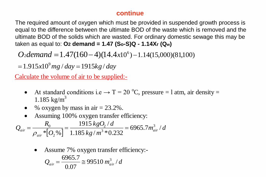
The required amount of oxygen which must be provided in suspended growth process is
equal to the difference between the ultimate BOD of the waste which is removed and the
ultimate BOD of the solids which are wasted. For ordinary domestic sewage this may be
taken as equal to: O2 demand = 1.47 (So-S)Q - 1.14Xr (Qw)
continue
daykgdaymgx
xdemandO
/1915/10915.1
)100,81)(000,15(14.1)10
9
62 4.14)(4160(47.1
Calculate the volume of air to be supplied:-
At standard conditions i.e → T = 20 oC, pressure = l atm, air density =
1.185 kg/m3
% oxygen by mass in air = 23.2%.
Assuming 100% oxygen transfer efficiency:
dm
mkg
dkgO
O
RQ air
air
air /7.6965232.0*/185.1
/1915
%*
3
3
2
2
0
Assume 7% oxygen transfer efficiency:-
dmQ airair /9951007.0
7.6965 3
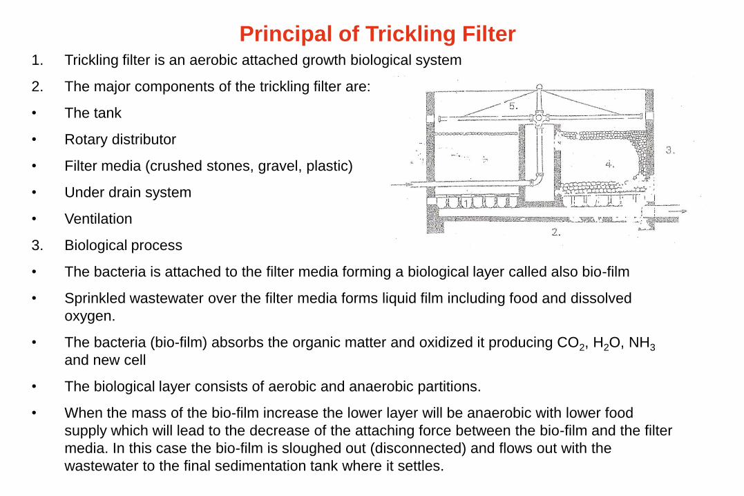
Principal of Trickling Filter1. Trickling filter is an aerobic attached growth biological system
2. The major components of the trickling filter are:
• The tank
• Rotary distributor
• Filter media (crushed stones, gravel, plastic)
• Under drain system
• Ventilation
3. Biological process
• The bacteria is attached to the filter media forming a biological layer called also bio-film
• Sprinkled wastewater over the filter media forms liquid film including food and dissolved
oxygen.
• The bacteria (bio-film) absorbs the organic matter and oxidized it producing CO2, H2O, NH3
and new cell
• The biological layer consists of aerobic and anaerobic partitions.
• When the mass of the bio-film increase the lower layer will be anaerobic with lower food
supply which will lead to the decrease of the attaching force between the bio-film and the filter
media. In this case the bio-film is sloughed out (disconnected) and flows out with the
wastewater to the final sedimentation tank where it settles.
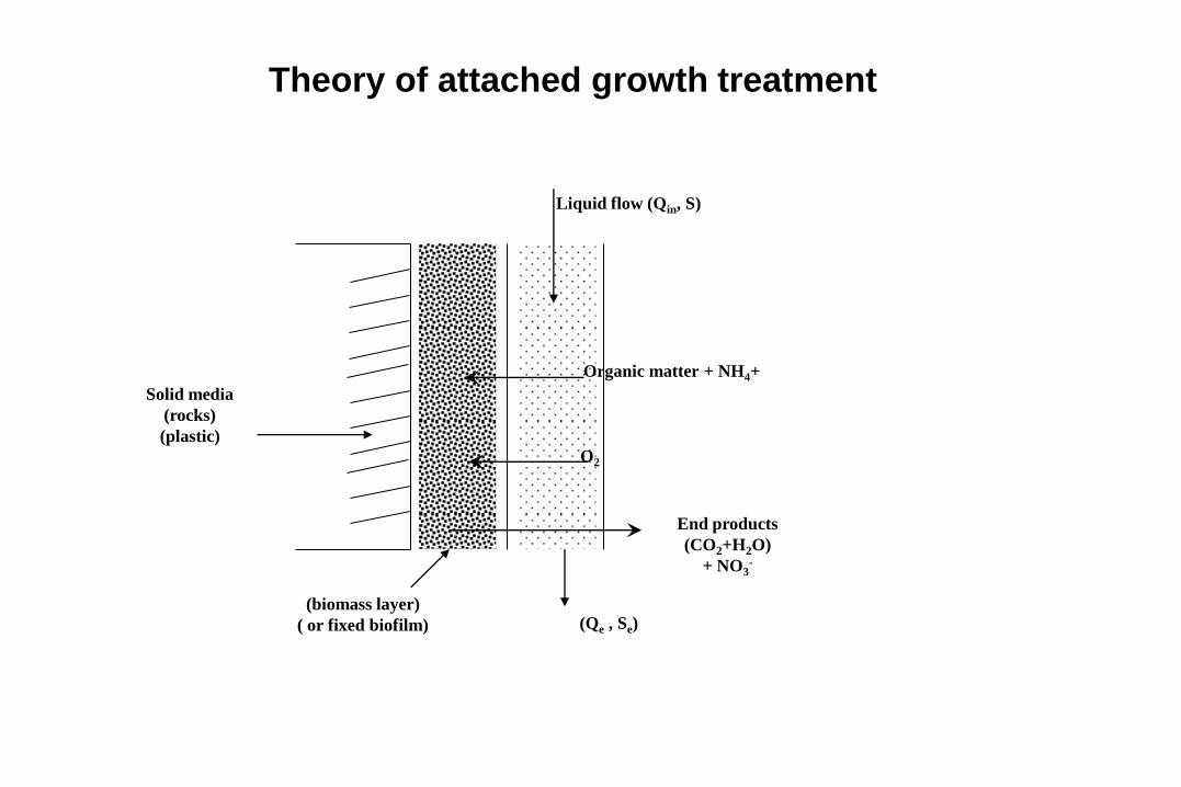
Theory of attached growth treatment
Liquid flow (Qin, S)
Organic matter + NH4+
O2
End products
(CO2+H2O)
+ NO3-
(Qe , Se)
Solid media
(rocks)
(plastic)
(biomass layer)
( or fixed biofilm)
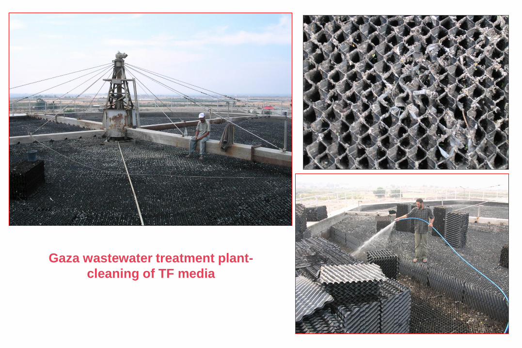
Gaza wastewater treatment plant-
cleaning of TF media
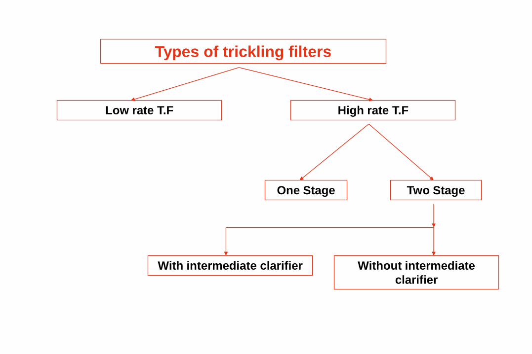
Types of trickling filters
Low rate T.F High rate T.F
One Stage Two Stage
With intermediate clarifier Without intermediate
clarifier
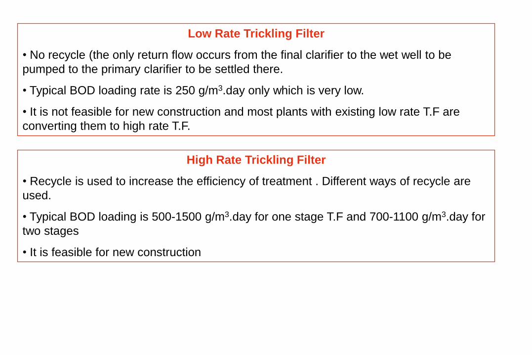
Low Rate Trickling Filter
• No recycle (the only return flow occurs from the final clarifier to the wet well to be
pumped to the primary clarifier to be settled there.
• Typical BOD loading rate is 250 g/m3.day only which is very low.
• It is not feasible for new construction and most plants with existing low rate T.F are
converting them to high rate T.F.
High Rate Trickling Filter
• Recycle is used to increase the efficiency of treatment . Different ways of recycle are
used.
• Typical BOD loading is 500-1500 g/m3.day for one stage T.F and 700-1100 g/m3.day for
two stages
• It is feasible for new construction
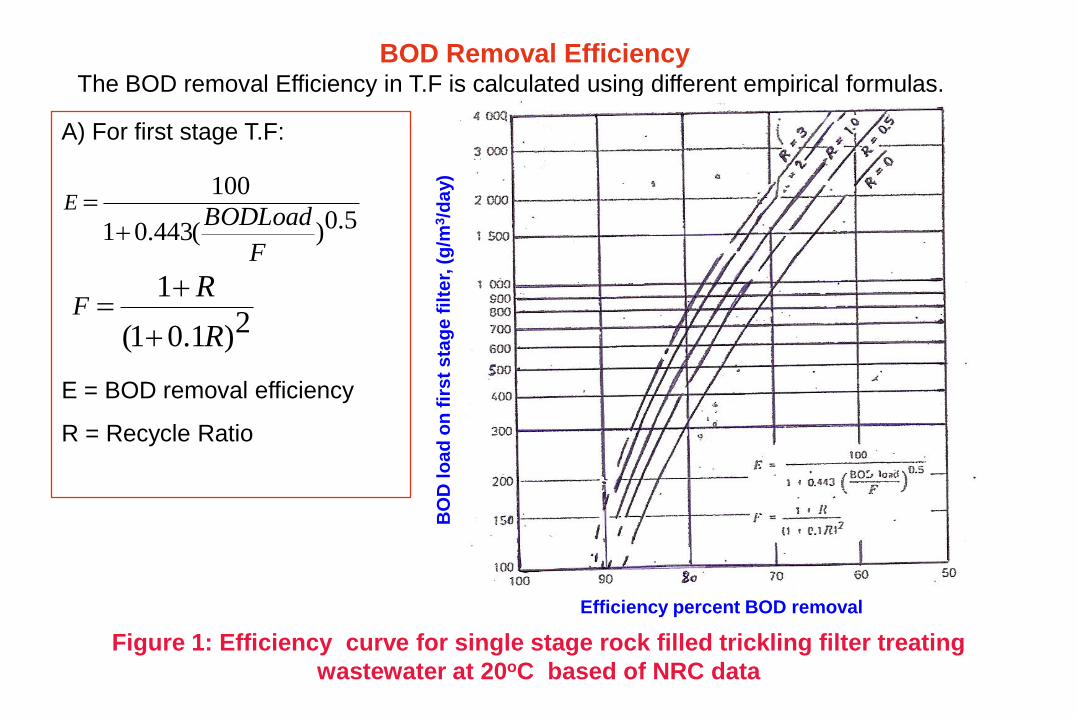
A) For first stage T.F:
E = BOD removal efficiency
R = Recycle Ratio
2)1.01(
1
R
RF
5.0)(443.01
100
F
BODLoadE
BOD Removal EfficiencyThe BOD removal Efficiency in T.F is calculated using different empirical formulas.
Figure 1: Efficiency curve for single stage rock filled trickling filter treating
wastewater at 20oC based of NRC data
Efficiency percent BOD removal
BO
D lo
ad
on
fir
st
sta
ge
fil
ter,
(g
/m3/d
ay)
Trickling filter efficiency at ToC percent
Tri
ckli
ng
filte
r eff
icie
nc
y a
t 2
0oC
perc
en
t
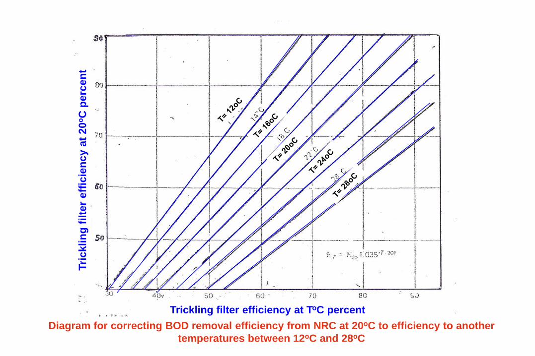
Diagram for correcting BOD removal efficiency from NRC at 20oC to efficiency to another
temperatures between 12oC and 28oC
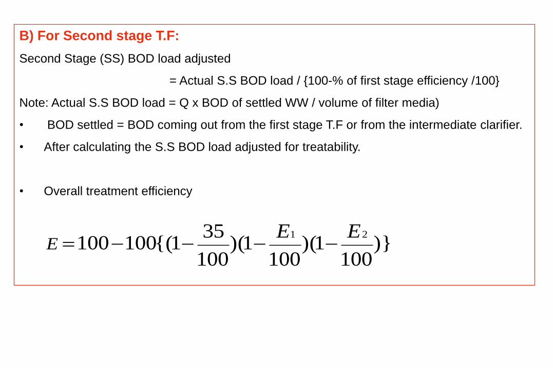
B) For Second stage T.F:
Second Stage (SS) BOD load adjusted
= Actual S.S BOD load / {100-% of first stage efficiency /100}
Note: Actual S.S BOD load = Q x BOD of settled WW / volume of filter media)
• BOD settled = BOD coming out from the first stage T.F or from the intermediate clarifier.
• After calculating the S.S BOD load adjusted for treatability.
• Overall treatment efficiency
)}100
1)(100
1)(100
351{(100100
21 EEE
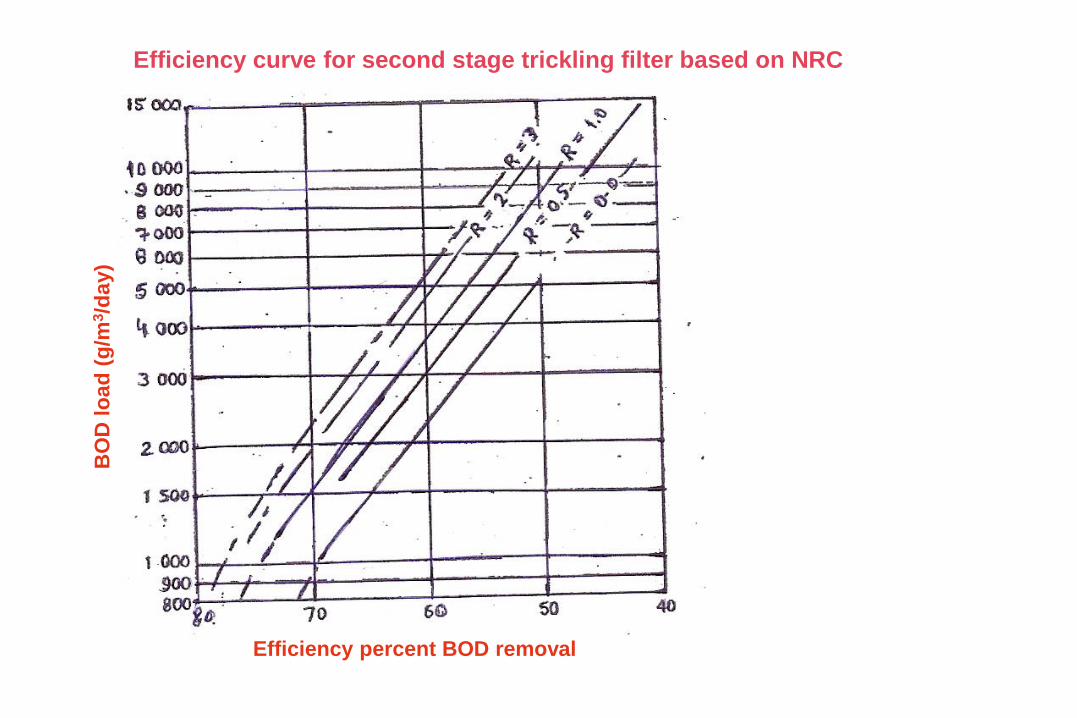
Efficiency curve for second stage trickling filter based on NRC
Efficiency percent BOD removal
BO
D lo
ad
(g
/m3/d
ay)
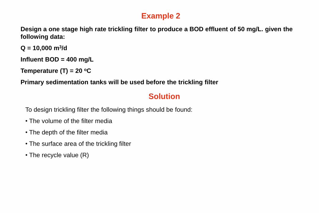
Example 2
Design a one stage high rate trickling filter to produce a BOD effluent of 50 mg/L. given the
following data:
Q = 10,000 m3/d
Influent BOD = 400 mg/L
Temperature (T) = 20 oC
Primary sedimentation tanks will be used before the trickling filter
Solution
To design trickling filter the following things should be found:
• The volume of the filter media
• The depth of the filter media
• The surface area of the trickling filter
• The recycle value (R)
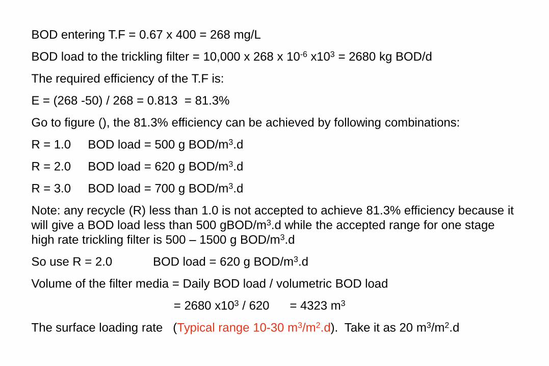
BOD entering T.F = 0.67 x 400 = 268 mg/L
BOD load to the trickling filter = 10,000 x 268 x 10-6 x103 = 2680 kg BOD/d
The required efficiency of the T.F is:
E = (268 -50) / 268 = 0.813 = 81.3%
Go to figure (), the 81.3% efficiency can be achieved by following combinations:
R = 1.0 BOD load = 500 g BOD/m3.d
R = 2.0 BOD load = 620 g BOD/m3.d
R = 3.0 BOD load = 700 g BOD/m3.d
Note: any recycle (R) less than 1.0 is not accepted to achieve 81.3% efficiency because it
will give a BOD load less than 500 gBOD/m3.d while the accepted range for one stage
high rate trickling filter is 500 – 1500 g BOD/m3.d
So use R = 2.0 BOD load = 620 g BOD/m3.d
Volume of the filter media = Daily BOD load / volumetric BOD load
= 2680 x103 / 620 = 4323 m3
The surface loading rate (Typical range 10-30 m3/m2.d). Take it as 20 m3/m2.d
Q
P.S
TFF.S.T
Q’R
QR
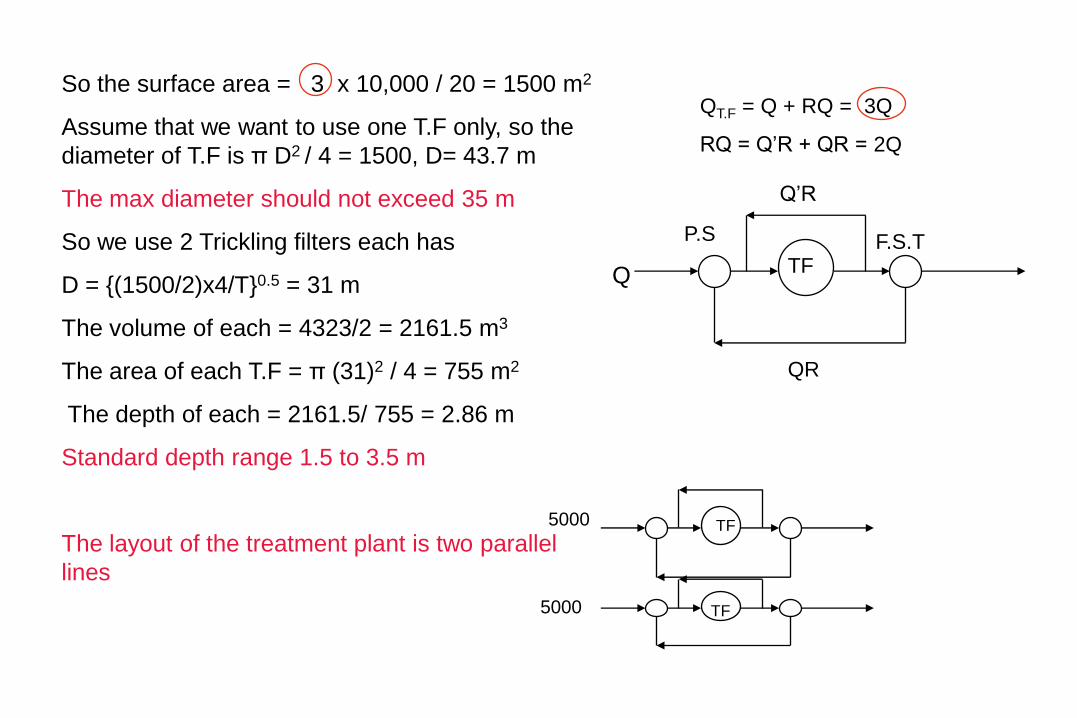
QT.F = Q + RQ = 3Q
RQ = Q’R + QR = 2Q
So the surface area = 3 x 10,000 / 20 = 1500 m2
Assume that we want to use one T.F only, so the
diameter of T.F is π D2 / 4 = 1500, D= 43.7 m
The max diameter should not exceed 35 m
So we use 2 Trickling filters each has
D = {(1500/2)x4/T}0.5 = 31 m
The volume of each = 4323/2 = 2161.5 m3
The area of each T.F = π (31)2 / 4 = 755 m2
The depth of each = 2161.5/ 755 = 2.86 m
Standard depth range 1.5 to 3.5 m
The layout of the treatment plant is two parallel
lines
5000 TF
TF5000


![LITHIUM OXIDE - الصفحات الشخصيةsite.iugaza.edu.ps › bqeshta › files › 2010 › 02 › 94398_13.pdf · 2009-04-26 · LITHIUM OXIDE [12057-24-8] Formula: Li2O;](https://img.dokumen.tips/doc/110x75/5f0d63d17e708231d43a1d60/lithium-oxide-site-a-bqeshta-a-files-a-2010.jpg)