Embed Size (px)
Citation preview
SDN Integration with Nuage Networks O R A C L E W H I T E P A P E R | A P R I L 2 0 1 9
2 | SDN INTEGRATION WITH NUAGE NETWORKS
Disclaimer The following is intended to outline our general product direction. It is intended for information purposes only, and may not be incorporated into any contract. It is not a commitment to deliver any material, code, or functionality, and should not be relied upon in making purchasing decisions. The development, release, and timing of any features or functionality described for Oracle’s products remains at the sole discretion of Oracle.
Revision History The following revisions have been made to this white paper since its initial publication:
Date Revision
April 17, 2019 Initial publication
You can find the most recent versions of the Oracle Cloud Infrastructure white papers at https://cloud.oracle.com/iaas/technical-resources.
3 | SDN INTEGRATION WITH NUAGE NETWORKS
Table of Contents Overview 4
Software Requirements 4
Assumptions 4
Target Scenario 5
Technical Architecture 5
Deploying SDN Integration with Nuage Networks on Oracle Cloud Infrastructure 7
Create the Network Infrastructure (VCN and Subnets) 7
Create an Instance for the VSC 9
Installing and Configuring Virtualized Services Controller 16
Install VSC 17
Configure VSC 22
Installing Virtual Routing and Switching 29
Prerequisites 30
Install VRS 30
Nuage Networks SDN Tests 36
Appendix A: Attach Secondary VNICs in Oracle Cloud Infrastructure 39
Appendix B: Virtualized Services Controller BOF File 42
Appendix C: Virtualized Services Controller Configuration File 42
Appendix D: Virtual Routing and Switching Configuration File 46
Resources 51
4 | SDN INTEGRATION WITH NUAGE NETWORKS
Overview This white paper is a detailed deployment guide for the Nuage Networks from Nokia software-defined networking (SDN) solution within Oracle Cloud Infrastructure. It describes the reference architecture and installation steps as well as the testing procedures performed during the build.
This paper is intended for network architects and network administrators who wants to seamlessly extend their on-premises services to the cloud by using the Nuage Networks SDN solution.
Software Requirements This paper was written based on the following software requirements:
• Nuage Networks Virtual Routing and Switching (VRS) and Virtualized Services Controller (VSC) for KVM, release 5.3.3
• Oracle Linux 7.4 or later
• CentOS 7
Assumptions This paper makes the following assumptions:
• You have knowledge of KVM and how to work with the hypervisor.
• You have knowledge of Linux system administration and can set and edit network files.
• You have knowledge of the Nuage Networks SDN solution, including Virtual Routing and Switching (VRS), Virtualized Services Controller (VSC), and Virtualized Services Directory (VSD).
• You understand how to install an operating system as a guest or you know how to copy a virtual disk image between disks.
• You understand how your guest should share storage.
• You have created the required resources for your environment, such as a virtual cloud network (VCN) and network-related information.
• You know how to provision a bare metal compute instance.
• Your KVM host has internet access.
• You have a Nuage Networks VRS and VSC qcow2 image for KVM. You will import this virtual machine image in qcow2 format.
5 | SDN INTEGRATION WITH NUAGE NETWORKS
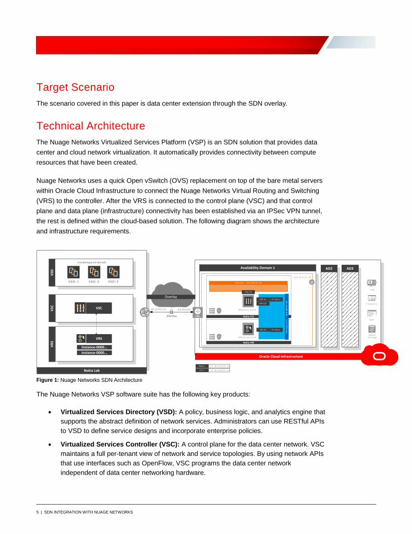
Target Scenario The scenario covered in this paper is data center extension through the SDN overlay.
Technical Architecture The Nuage Networks Virtualized Services Platform (VSP) is an SDN solution that provides data center and cloud network virtualization. It automatically provides connectivity between compute resources that have been created.
Nuage Networks uses a quick Open vSwitch (OVS) replacement on top of the bare metal servers within Oracle Cloud Infrastructure to connect the Nuage Networks Virtual Routing and Switching (VRS) to the controller. After the VRS is connected to the control plane (VSC) and that control plane and data plane (infrastructure) connectivity has been established via an IPSec VPN tunnel, the rest is defined within the cloud-based solution. The following diagram shows the architecture and infrastructure requirements.
Figure 1: Nuage Networks SDN Architecture
The Nuage Networks VSP software suite has the following key products:
• Virtualized Services Directory (VSD): A policy, business logic, and analytics engine that supports the abstract definition of network services. Administrators can use RESTful APIs to VSD to define service designs and incorporate enterprise policies.
• Virtualized Services Controller (VSC): A control plane for the data center network. VSC maintains a full per-tenant view of network and service topologies. By using network APIs that use interfaces such as OpenFlow, VSC programs the data center network independent of data center networking hardware.
Nokia VSC
Availability Domain 1 AD2
BM.D enseI O1.36
VNI C1
VNI C2
AD3
I P : 10 .0 .10 3 .0 / 2 4
I P : 10 .0 .10 4 .0 / 2 4
Mgmt
Ct r l
VS D - 1 VS D - 2
VSC
VRS
VSD
VSC
VRS
Instance-0000...Instance-0000...
Nokia Lab
VCN 10 .0 .0 .0 / 16
I AM
T elemet r y
Aud it
Obj ec tS t or a ge
VPN IPSec
135 .13 .2 5 5 .2 2 9 12 9 .146 .13 .5 1
BM.D enseI O1.36
VNI C1
Nokia VRS
Overlay
Oracle Cloud Infrastructure
VS D - 3
cna @xmpp.sir la b.la b
Over la y - 10 .0 .10 4 .0 / 2 4
VNI C3
Ma
nage
men
t -
10.0
.103.
0/
24
Pr ima r y
Pr ima r y

6 | SDN INTEGRATION WITH NUAGE NETWORKS
• Virtual Routing and Switching (VRS): A virtual endpoint for network services. VRS detects changes in the compute environment as they occur, and it triggers policy-based responses to ensure that applications have the network connectivity that they need.
Following diagram depicts the components in the solution:
Figure 2: Nuage Networks VSP
This paper deploys and configures both VSC and VRS in Oracle Cloud Infrastructure and connects to the customer’s network. The management plane (VSD) remains in the customer’s facilities and is out of the scope of this paper.
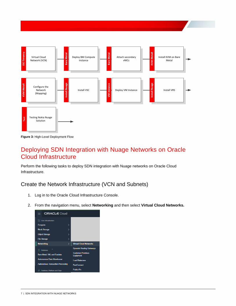
The following diagram illustrates the steps for deploying Nuage Networks VSC and VRS in Oracle Cloud Infrastructure. This process can be automated through Terraform. Stay tuned!
7 | SDN INTEGRATION WITH NUAGE NETWORKS
Inst
all N
uage
OCI
Ten
ancy
Bare
Met
al
Deploy BM Compute Instance
Bare
Met
al
Attach secondary vNICs
Virtual Cloud Network (VCN)
KVM
INst
all
Install KVM on Bare Metal
KVM
INst
all
Configure the Network
(Mapping)
Inst
all N
uage
Install VSC Install VRS
Test
VM In
stan
ce
Deploy VM Instance
Testing Nokia Nuage Solution
Figure 3: High-Level Deployment Flow
Deploying SDN Integration with Nuage Networks on Oracle Cloud Infrastructure Perform the following tasks to deploy SDN integration with Nuage networks on Oracle Cloud Infrastructure.
Create the Network Infrastructure (VCN and Subnets)
1. Log in to the Oracle Cloud Infrastructure Console.
2. From the navigation menu, select Networking and then select Virtual Cloud Networks.
8 | SDN INTEGRATION WITH NUAGE NETWORKS
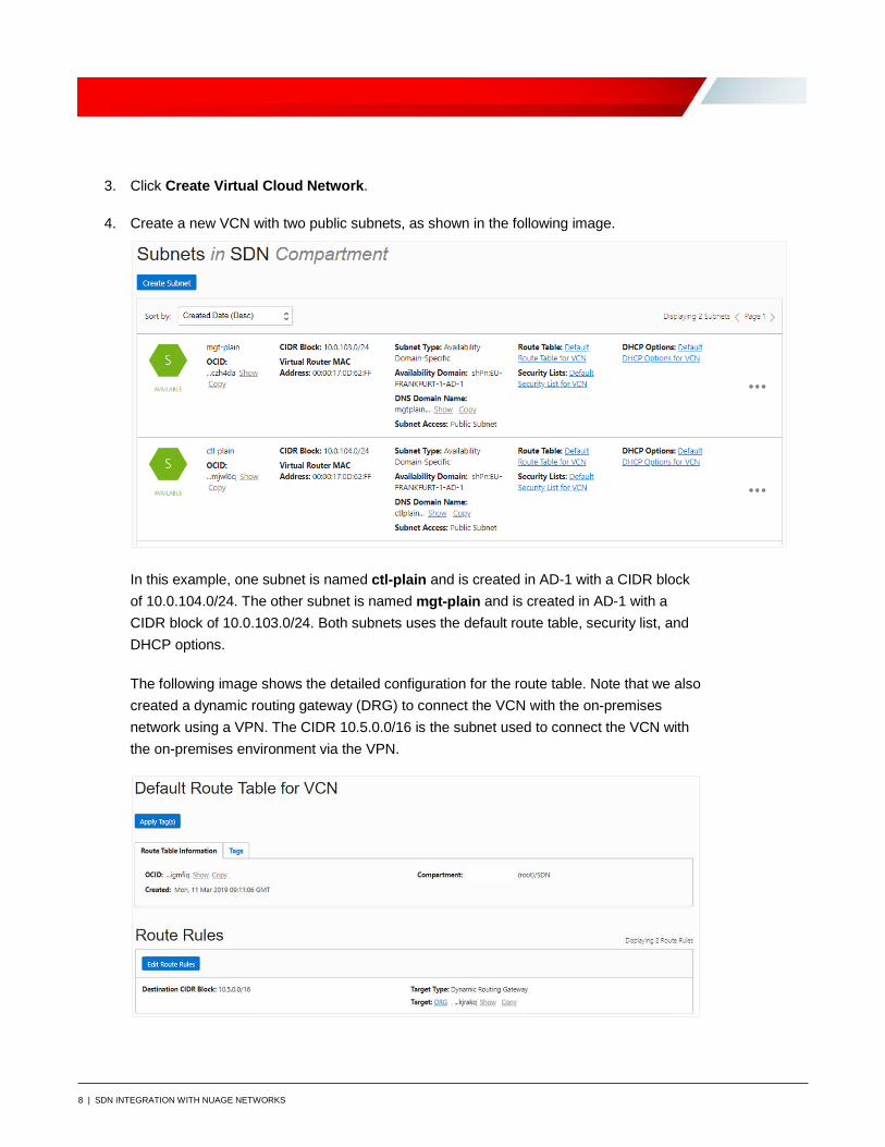
3. Click Create Virtual Cloud Network.
4. Create a new VCN with two public subnets, as shown in the following image.
In this example, one subnet is named ctl-plain and is created in AD-1 with a CIDR block of 10.0.104.0/24. The other subnet is named mgt-plain and is created in AD-1 with a CIDR block of 10.0.103.0/24. Both subnets uses the default route table, security list, and DHCP options.
The following image shows the detailed configuration for the route table. Note that we also created a dynamic routing gateway (DRG) to connect the VCN with the on-premises network using a VPN. The CIDR 10.5.0.0/16 is the subnet used to connect the VCN with the on-premises environment via the VPN.
9 | SDN INTEGRATION WITH NUAGE NETWORKS
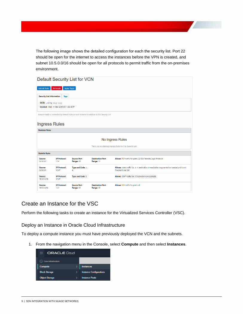
The following image shows the detailed configuration for each the security list. Port 22 should be open for the internet to access the instances before the VPN is created, and subnet 10.5.0.0/16 should be open for all protocols to permit traffic from the on-premises environment.
Create an Instance for the VSC Perform the following tasks to create an instance for the Virtualized Services Controller (VSC).
Deploy an Instance in Oracle Cloud Infrastructure
To deploy a compute instance you must have previously deployed the VCN and the subnets.
1. From the navigation menu in the Console, select Compute and then select Instances.
10 | SDN INTEGRATION WITH NUAGE NETWORKS
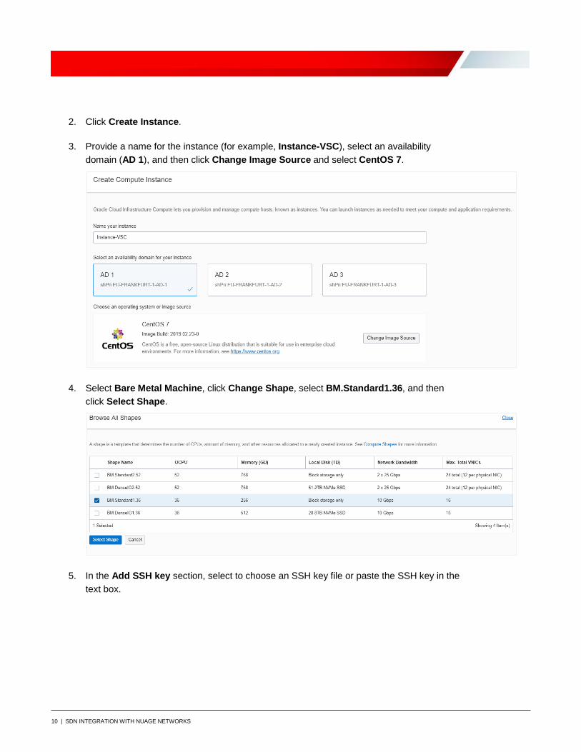
2. Click Create Instance.
3. Provide a name for the instance (for example, Instance-VSC), select an availability domain (AD 1), and then click Change Image Source and select CentOS 7.
4. Select Bare Metal Machine, click Change Shape, select BM.Standard1.36, and then click Select Shape.
5. In the Add SSH key section, select to choose an SSH key file or paste the SSH key in the text box.
11 | SDN INTEGRATION WITH NUAGE NETWORKS
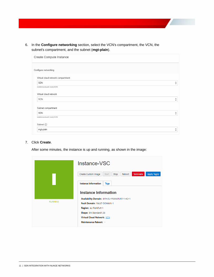
6. In the Configure networking section, select the VCN's compartment, the VCN, the subnet's compartment, and the subnet (mgt-plain).
7. Click Create.
After some minutes, the instance is up and running, as shown in the image:
12 | SDN INTEGRATION WITH NUAGE NETWORKS
Install KVM Software in Linux (CentOS)
1. Log in to the instance SSH connection with any software like PuTTY or MobaXterm.
2. Edit the /etc/default/grub file and add the following line: intel_iommu=on, as follows: GRUB_CMDLINE_LINUX="crashkernel=auto LANG=en_US.UTF-8 transparent_hugepage=never console=tty0 console=ttyS0,9600 libiscsi.debug_libiscsi_eh=1 rd.luks=0 rd.lvm=0 rd.md=0 rd.dm=0 ip=dhcp netroot=iscsi:169.254.0.2::::iqn.2015-02.oracle.boot:uefi iscsi_param=node.session.timeo.replacement_timeout=6000 net.ifnames=1 intel_iommu=on"
3. Run the following commands to install the KVM software, and start and enable the libvirtd service: # sudo su - # yum install qemu-kvm qemu-img virt-manager libvirt libvirt-python libvirt-client virt-install virt-viewer bridge-utils # systemctl start libvirtd # systemctl enable libvirtd
Prepare the Network
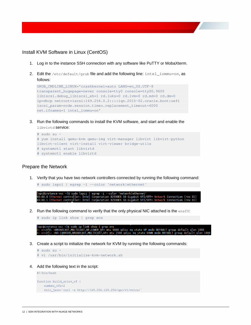
1. Verify that you have two network controllers connected by running the following command: # sudo lspci | egrep -i --color 'network|ethernet'
2. Run the following command to verify that the only physical NIC attached is the ensf0: # sudo ip link show | grep ens
3. Create a script to initialize the network for KVM by running the following commands: # sudo su – # vi /usr/bin/initialize-kvm-network.sh
4. Add the following text in the script: #!/bin/bash function build_sriov_vf { number_vfs=2 vnic_json=`curl -s http://169.254.169.254/opc/v1/vnics/`

13 | SDN INTEGRATION WITH NUAGE NETWORKS
vnic_count=`echo ${vnic_json} | jq -r 'length'` count=0 for field in macAddr vlanTag do read -ra ${field} <<< `echo ${vnic_json} | jq -r '.[0:length] |.[].'"${field}"''` done while [ ${count} -lt ${vnic_count} ] do if [ ${vlanTag[${count}]} -eq 0 ] then physdev=`ip -o link show | grep ${macAddr[${count}]} | awk -F: '{gsub(/\s+/,"", $2);print $2}'` echo ${number_vfs} > /sys/class/net/${physdev}/device/sriov_numvfs wait bridge link set dev ${physdev} hwmode vepa fi if [ ${vlanTag[${count}]} -gt 0 ] then (( vf_index = count - 1 )) ip link set ${physdev} vf ${vf_index} mac ${macAddr[${count}]} spoofchk off fi (( count = count + 1 )) done } build_sriov_vf #wait 30s to OS enable VFs sleep 30s
5. Change permissions to the file to be able to run it by running the following command: # chmod +x /usr/bin/initialize-kvm-network.sh
6. Run the script to enable virtual function devices by running the following command: # /usr/bin/initialize-kvm-network.sh
7. View the virtual devices created by running the following command: # lshw -c network -businfo
In the output, note that the virtual functions added are enp3s16 and enp3s16f2.
14 | SDN INTEGRATION WITH NUAGE NETWORKS
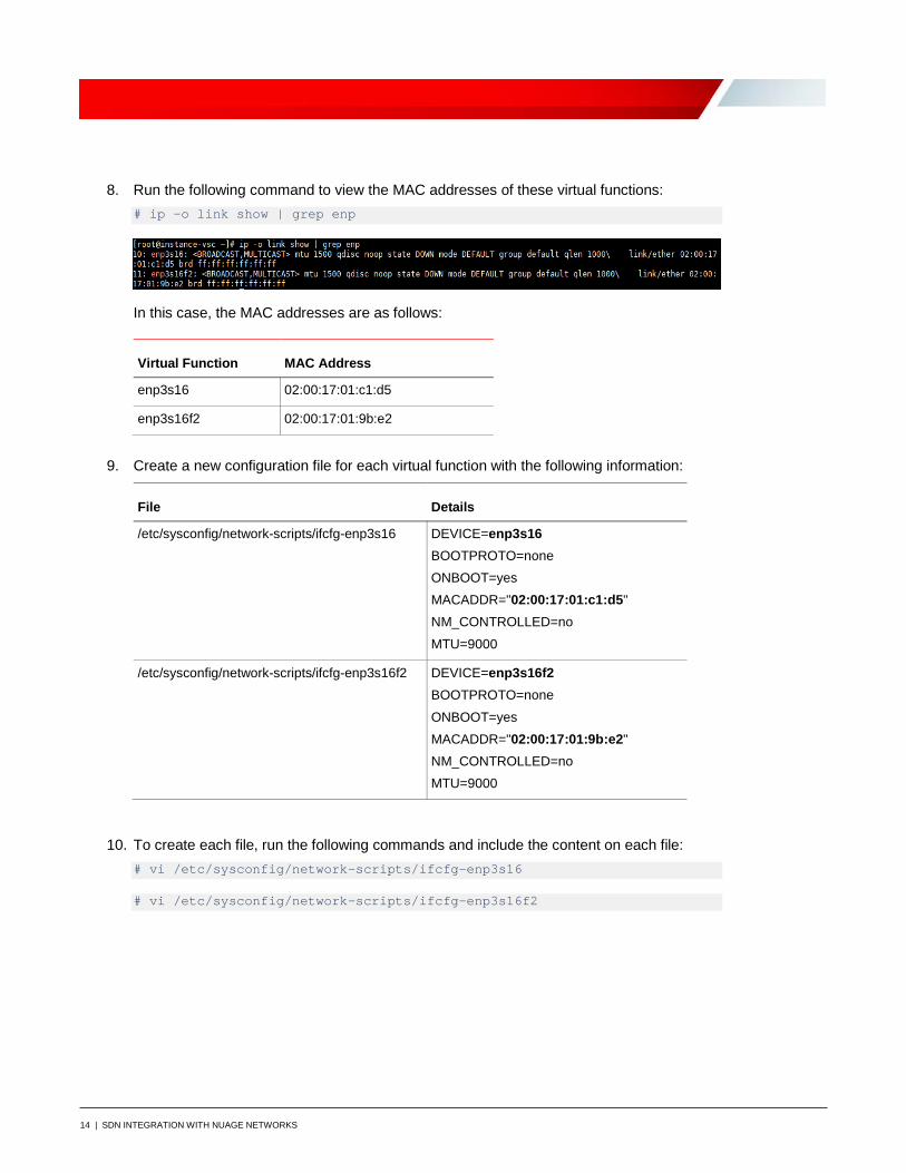
8. Run the following command to view the MAC addresses of these virtual functions: # ip -o link show | grep enp
In this case, the MAC addresses are as follows:
Virtual Function MAC Address
enp3s16 02:00:17:01:c1:d5
enp3s16f2 02:00:17:01:9b:e2
9. Create a new configuration file for each virtual function with the following information:
File Details
/etc/sysconfig/network-scripts/ifcfg-enp3s16 DEVICE=enp3s16 BOOTPROTO=none ONBOOT=yes MACADDR="02:00:17:01:c1:d5" NM_CONTROLLED=no MTU=9000
/etc/sysconfig/network-scripts/ifcfg-enp3s16f2 DEVICE=enp3s16f2 BOOTPROTO=none ONBOOT=yes MACADDR="02:00:17:01:9b:e2" NM_CONTROLLED=no MTU=9000
10. To create each file, run the following commands and include the content on each file: # vi /etc/sysconfig/network-scripts/ifcfg-enp3s16
# vi /etc/sysconfig/network-scripts/ifcfg-enp3s16f2
15 | SDN INTEGRATION WITH NUAGE NETWORKS
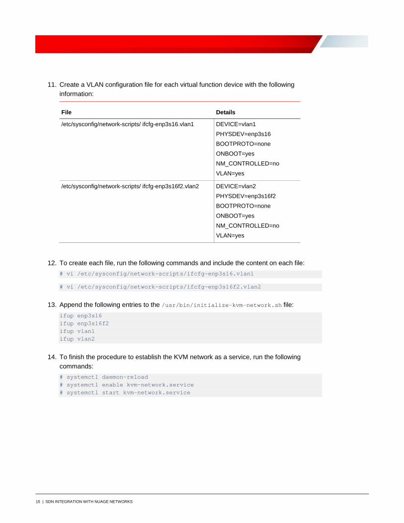
11. Create a VLAN configuration file for each virtual function device with the following information:
File Details
/etc/sysconfig/network-scripts/ ifcfg-enp3s16.vlan1 DEVICE=vlan1 PHYSDEV=enp3s16 BOOTPROTO=none ONBOOT=yes NM_CONTROLLED=no VLAN=yes
/etc/sysconfig/network-scripts/ ifcfg-enp3s16f2.vlan2 DEVICE=vlan2 PHYSDEV=enp3s16f2 BOOTPROTO=none ONBOOT=yes NM_CONTROLLED=no VLAN=yes
12. To create each file, run the following commands and include the content on each file: # vi /etc/sysconfig/network-scripts/ifcfg-enp3s16.vlan1
# vi /etc/sysconfig/network-scripts/ifcfg-enp3s16f2.vlan2
13. Append the following entries to the /usr/bin/initialize-kvm-network.sh file: ifup enp3s16 ifup enp3s16f2 ifup vlan1 ifup vlan2
14. To finish the procedure to establish the KVM network as a service, run the following commands: # systemctl daemon-reload # systemctl enable kvm-network.service # systemctl start kvm-network.service
16 | SDN INTEGRATION WITH NUAGE NETWORKS
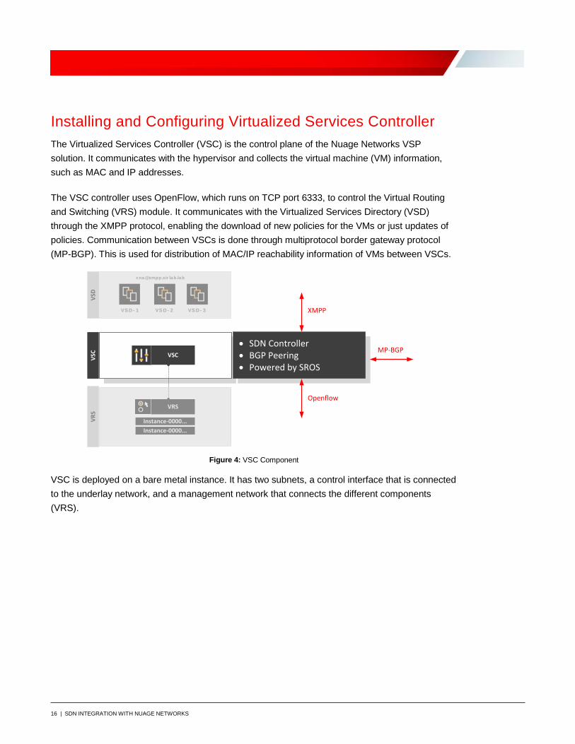
Installing and Configuring Virtualized Services Controller The Virtualized Services Controller (VSC) is the control plane of the Nuage Networks VSP solution. It communicates with the hypervisor and collects the virtual machine (VM) information, such as MAC and IP addresses.
The VSC controller uses OpenFlow, which runs on TCP port 6333, to control the Virtual Routing and Switching (VRS) module. It communicates with the Virtualized Services Directory (VSD) through the XMPP protocol, enabling the download of new policies for the VMs or just updates of policies. Communication between VSCs is done through multiprotocol border gateway protocol (MP-BGP). This is used for distribution of MAC/IP reachability information of VMs between VSCs.
VS D - 1 VS D - 2
VSC
VRS
VSD
VSC
VRS
Instance-0000...Instance-0000...
VS D - 3
cna @xmpp.sir la b.la b
• SDN Controller• BGP Peering• Powered by SROS
Openflow
XMPP
MP-BGP
Figure 4: VSC Component
VSC is deployed on a bare metal instance. It has two subnets, a control interface that is connected to the underlay network, and a management network that connects the different components (VRS).
17 | SDN INTEGRATION WITH NUAGE NETWORKS
VSC
Bare
Met
al
BOF(mgmt) CONTROLIP IP
br-mgmt br-ctrl
bondeth0
IP system
SSHXMPP to VSD
Openflow to VRSBGP to VSC
104103
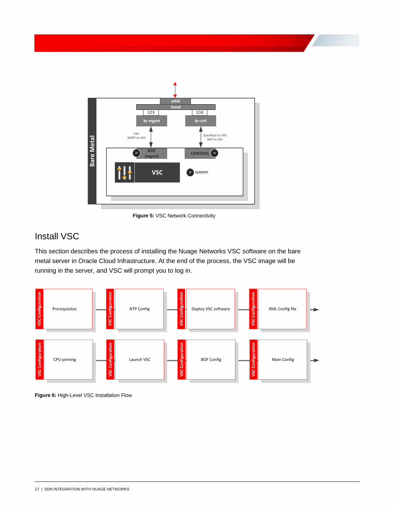
Figure 5: VSC Network Connectivity
Install VSC This section describes the process of installing the Nuage Networks VSC software on the bare metal server in Oracle Cloud Infrastructure. At the end of the process, the VSC image will be running in the server, and VSC will prompt you to log in.
VSC
Conf
igur
atio
n
NTP Config Deploy VSC softwarePrerequisites XML Config file
VSC
Conf
igur
atio
n
VSC
Conf
igur
atio
n
VSC
Conf
igur
atio
n
VSC
Conf
igur
atio
n
Launch VSC BOF ConfigCPU pinning Main Config
VSC
Conf
igur
atio
n
VSC
Conf
igur
atio
n
VSC
Conf
igur
atio
n
Figure 6: High-Level VSC Installation Flow

18 | SDN INTEGRATION WITH NUAGE NETWORKS
Prerequisites
Before deploying the VSC, the following requirements must be met. Perform any necessary tasks as part of your planning exercise.
• An IP address is already assigned for the management network.
• Two independent network interfaces are set up for management and data traffic, connected to two Linux bridge interfaces. These instructions assume bridges br0 for management and br1 for data have been created and attached.
• At least one NTP server has been configured and synchronized. When you set up a server, you must set up an NTP server for all the components. When you define a VM, it gets a timestamp, which cannot deviate more than 10 seconds.
• A way to copy the VSC software files to the server is required.
After these requirements are met, install the required dependencies as follows:
# yum install kvm libvirt bridge-utils service libvirtd start chkconfig libvirtd on
To Install the NTP Server
1. Install the NTP server: [opc@instance-vsc ~]$ sudo su [root@instance-vsc opc]# yum install ntp
2. To set your time zone, you might need to delete /etc/localtime first. Check the /etc/ntp.conf file and synchronize with the required values.
For this solution, we are adding the following lines:
[root@instance-vsc opc]# cat >> /etc/ntp.conf << EOF server 0.centos.pool.ntp.org iburst server 1.centos.pool.ntp.org iburst server 2.centos.pool.ntp.org iburst server 3.centos.pool.ntp.org iburst EOF
3. Restart the NTP daemon: [root@instance-vsc opc]# service ntpd restart [root@instance-vsc ntp]# date Tue Mar 12 13:32:32 GMT 2019

19 | SDN INTEGRATION WITH NUAGE NETWORKS
To Install VSC
Ensure that the previous section is completed before attempting this configuration. The libvirt API that is used to manage KVM includes a set of tools that allows you to create and manage VMs.
1. Start libvirtd and ensure that it's running: [root@instance-vsc opc]# systemctl start libvirtd
Note: To automatically start libvirtd at boot time, enter # systemctl enable libvirtd.
2. Copy the VSC software file to the destination host: [root@instance-vsc opc]# cd /var/lib/libvirt/images/ [root@instance-vsc images]# scp admin@source_host :/share/nfs/nuage/5.3.3/ Nuage-VSC-5.3.3-128.tar.gz ./ nuage-vsc- 5.3.3-128.tar.gz
3. Untar the VSC software file on the host. Note that for this deployment, we're implementing a single disk. [root@instance-vsc images]# tar xzvf nuage-vsc- 5.3.3-128.tar.gz [root@instance-vsc images]# cd single_disk/ [root@instance-vsc single_disk]# [root@instance-vsc single_disk]# cp vsc_singledisk.qcow2 ./vsc1.qcow2
4. Start the qcow2 installation: [root@instance-vsc single_disk]# chown qemu:qemu vsc1.qcow2
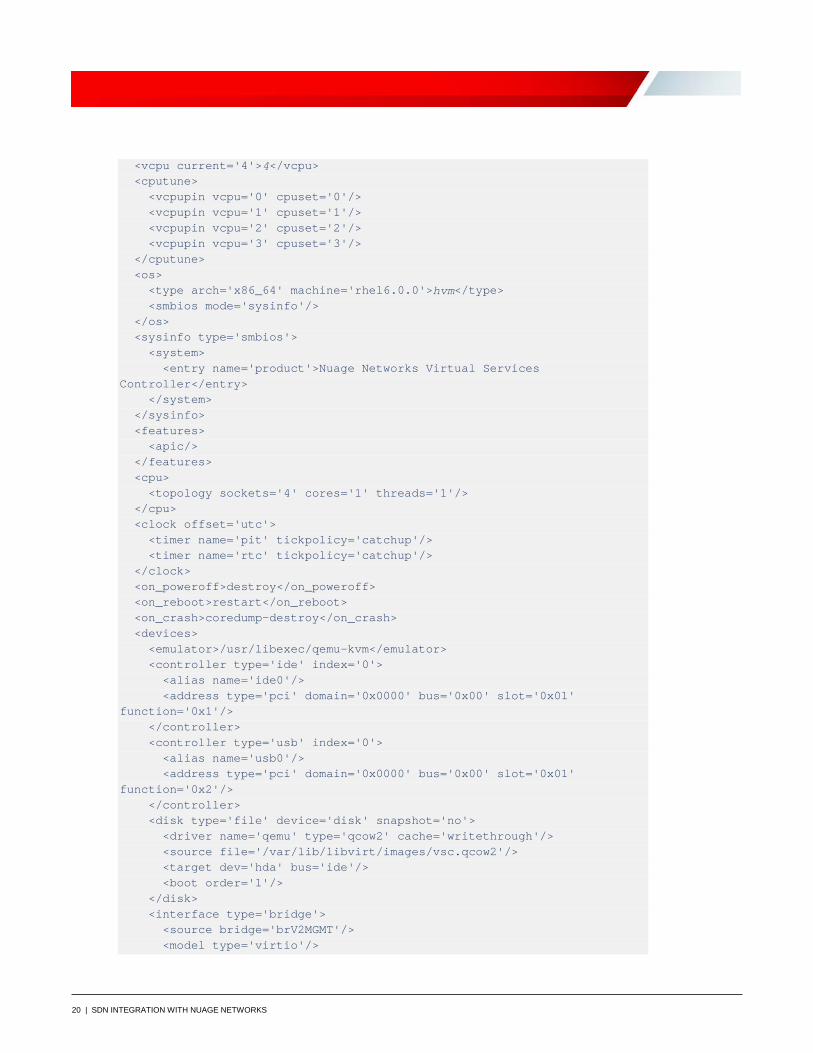
5. Use the vsc.xml file that was provided with the Nuage Networks software release to define a new VM. Edit the VSC XML configuration to rename the VM or the disk paths and filenames.
Note: In the following configuration, we pinned the vCPU to the available physical CPU. The cputune element provides details regarding the CPU tunable parameters. Use vcpupin to specify which of the bare metal instance’s physical CPUs will be pinned to the domain’s vCPU. For more information about tuning the CPU, go to https://libvirt.org/formatdomain.html.
[root@instance-vsc images]# cat vsc.xml <domain type='kvm'> <name>vsc</name> <description>Timos VM</description> <memory>4147483</memory> <currentMemory>4147483</currentMemory>
20 | SDN INTEGRATION WITH NUAGE NETWORKS
<vcpu current='4'>4</vcpu> <cputune> <vcpupin vcpu='0' cpuset='0'/> <vcpupin vcpu='1' cpuset='1'/> <vcpupin vcpu='2' cpuset='2'/> <vcpupin vcpu='3' cpuset='3'/> </cputune> <os> <type arch='x86_64' machine='rhel6.0.0'>hvm</type> <smbios mode='sysinfo'/> </os> <sysinfo type='smbios'> <system> <entry name='product'>Nuage Networks Virtual Services Controller</entry> </system> </sysinfo> <features> <apic/> </features> <cpu> <topology sockets='4' cores='1' threads='1'/> </cpu> <clock offset='utc'> <timer name='pit' tickpolicy='catchup'/> <timer name='rtc' tickpolicy='catchup'/> </clock> <on_poweroff>destroy</on_poweroff> <on_reboot>restart</on_reboot> <on_crash>coredump-destroy</on_crash> <devices> <emulator>/usr/libexec/qemu-kvm</emulator> <controller type='ide' index='0'> <alias name='ide0'/> <address type='pci' domain='0x0000' bus='0x00' slot='0x01' function='0x1'/> </controller> <controller type='usb' index='0'> <alias name='usb0'/> <address type='pci' domain='0x0000' bus='0x00' slot='0x01' function='0x2'/> </controller> <disk type='file' device='disk' snapshot='no'> <driver name='qemu' type='qcow2' cache='writethrough'/> <source file='/var/lib/libvirt/images/vsc.qcow2'/> <target dev='hda' bus='ide'/> <boot order='1'/> </disk> <interface type='bridge'> <source bridge='brV2MGMT'/> <model type='virtio'/>
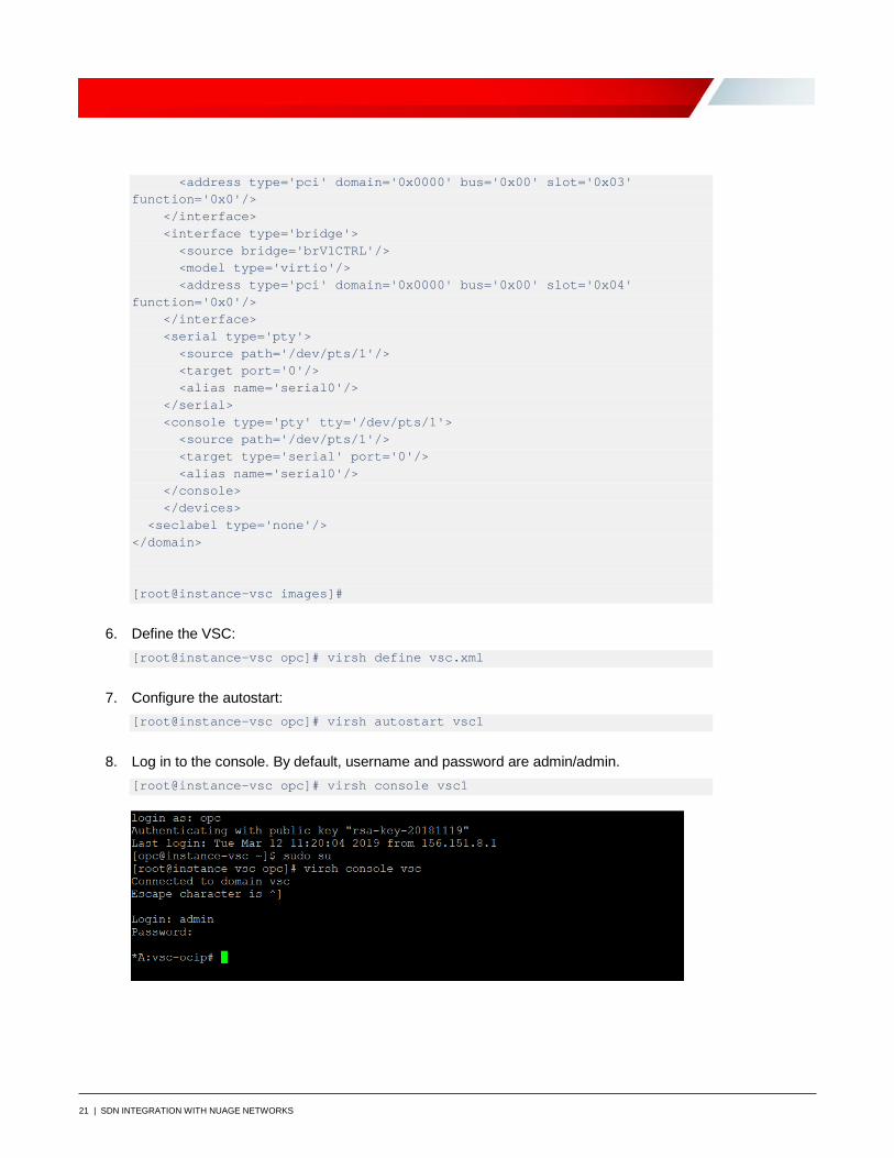
21 | SDN INTEGRATION WITH NUAGE NETWORKS
<address type='pci' domain='0x0000' bus='0x00' slot='0x03' function='0x0'/> </interface> <interface type='bridge'> <source bridge='brV1CTRL'/> <model type='virtio'/> <address type='pci' domain='0x0000' bus='0x00' slot='0x04' function='0x0'/> </interface> <serial type='pty'> <source path='/dev/pts/1'/> <target port='0'/> <alias name='serial0'/> </serial> <console type='pty' tty='/dev/pts/1'> <source path='/dev/pts/1'/> <target type='serial' port='0'/> <alias name='serial0'/> </console> </devices> <seclabel type='none'/> </domain> [root@instance-vsc images]#
6. Define the VSC: [root@instance-vsc opc]# virsh define vsc.xml
7. Configure the autostart: [root@instance-vsc opc]# virsh autostart vsc1
8. Log in to the console. By default, username and password are admin/admin. [root@instance-vsc opc]# virsh console vsc1

22 | SDN INTEGRATION WITH NUAGE NETWORKS
Configure VSC Next, you configure the VSC itself. For details about the commands being used, see the VSP Installation Guide.
The VSC controller configuration has the following components:
• Boot Options File (BOF): Contains the parameters needed to boot the device. Nuage Networks VSC uses a file named bof.cfg that is read on system boot and is used for some basic, low-level system configuration needed to successfully boot the VSC.
• Main configuration: Contains the main configuration, such as LAG and BGP settings.
Perform Boot Options File Configuration
For this solution, we're using a single-disk installation in which all configuration and boot images are stored on the CF1 disk (user disk). We will update the BOF file.
1. To navigate to the Boot Options File context, enter bof<Enter>. The prompt indicates a change to the bof context: *A:vsc-ocip# bof *A:vsc-ocip>bof#
2. Assign the management IP address: *A:vsc-ocip>bof# address 10.0.103.101/24 active
3. Configure the DNS servers: *A:vsc-ocip>bof# primary-dns 10.5.0.50
Note: You can configure up to three DNS servers: primary, secondary, and tertiary.
4. Configure the DNS domain: *A:vsc-ocip>bof# dns-domain sirlab.lab
5. Configure static routes for the management IP network: *A:vsc-ocip>bof# static-route 0.0.0.0/1 next-hop 10.0.103.1 *A:vsc-ocip>bof#128.0.0.0/1 next-hop 10.0.103.1
Note: A static route of 0.0.0.0/0 is not accepted by the BOF configuration. If a default route is required, configure two static routes, 0.0.0.0/1 and 128.0.0.0/1, instead.
23 | SDN INTEGRATION WITH NUAGE NETWORKS
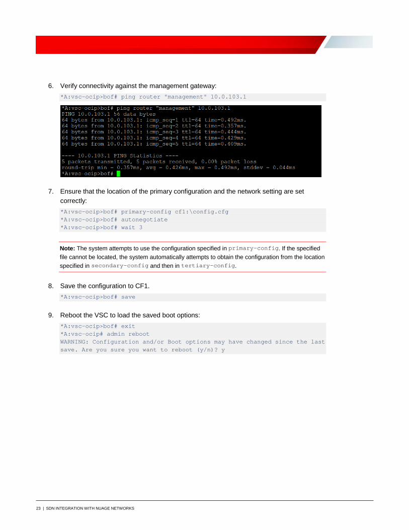
6. Verify connectivity against the management gateway: *A:vsc-ocip>bof# ping router "management" 10.0.103.1
7. Ensure that the location of the primary configuration and the network setting are set correctly: *A:vsc-ocip>bof# primary-config cf1:\config.cfg *A:vsc-ocip>bof# autonegotiate *A:vsc-ocip>bof# wait 3
Note: The system attempts to use the configuration specified in primary-config. If the specified file cannot be located, the system automatically attempts to obtain the configuration from the location specified in secondary-config and then in tertiary-config.
8. Save the configuration to CF1. *A:vsc-ocip>bof# save
9. Reboot the VSC to load the saved boot options: *A:vsc-ocip>bof# exit *A:vsc-ocip# admin reboot WARNING: Configuration and/or Boot options may have changed since the last save. Are you sure you want to reboot (y/n)? y
24 | SDN INTEGRATION WITH NUAGE NETWORKS
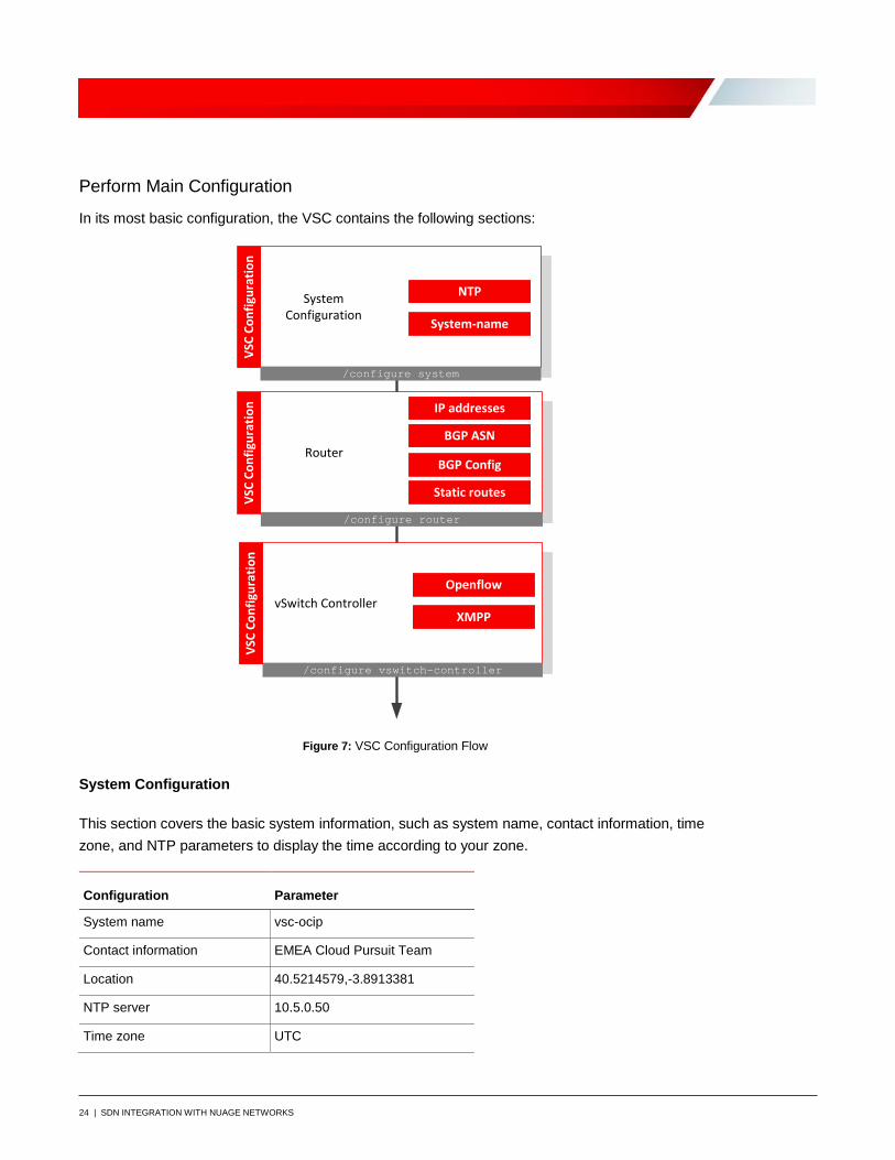
Perform Main Configuration
In its most basic configuration, the VSC contains the following sections:
VSC
Conf
igur
atio
n
System Configuration
NTP
/configure system
System-name
Router
IP addresses
/configure router
BGP ASN
Static routes
BGP Config
vSwitch ControllerOpenflow
/configure vswitch-controller
XMPP
VSC
Conf
igur
atio
nVS
C Co
nfig
urat
ion
Figure 7: VSC Configuration Flow
System Configuration
This section covers the basic system information, such as system name, contact information, time zone, and NTP parameters to display the time according to your zone.
Configuration Parameter
System name vsc-ocip
Contact information EMEA Cloud Pursuit Team
Location 40.5214579,-3.8913381
NTP server 10.5.0.50
Time zone UTC
25 | SDN INTEGRATION WITH NUAGE NETWORKS
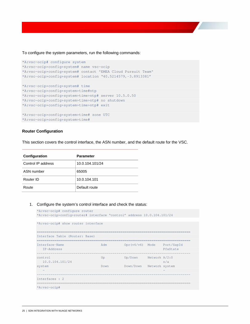
To configure the system parameters, run the following commands:
*A:vsc-ocip# configure system *A:vsc-ocip>config>system# name vsc-ocip *A:vsc-ocip>config>system# contact "EMEA Cloud Pursuit Team" *A:vsc-ocip>config>system# location “40.5214579,-3.8913381” *A:vsc-ocip>config>system# time *A:vsc-ocip>config>system>time#ntp *A:vsc-ocip>config>system>time>ntp# server 10.5.0.50 *A:vsc-ocip>config>system>time>ntp# no shutdown *A:vsc-ocip>config>system>time>ntp# exit *A:vsc-ocip>config>system>time# zone UTC *A:vsc-ocip>config>system>time#
Router Configuration
This section covers the control interface, the ASN number, and the default route for the VSC.
Configuration Parameter
Control IP address 10.0.104.101/24
ASN number 65005
Router ID 10.0.104.101
Route Default route
1. Configure the system’s control interface and check the status: *A:vsc-ocip# configure router *A:vsc-ocip>config>router# interface “control” address 10.0.104.101/24
*A:vsc-ocip# show router interface =============================================================================== Interface Table (Router: Base) =============================================================================== Interface-Name Adm Opr(v4/v6) Mode Port/SapId IP-Address PfxState ------------------------------------------------------------------------------- control Up Up/Down Network A/2:0 10.0.104.101/24 n/a system Down Down/Down Network system - - ------------------------------------------------------------------------------- Interfaces : 2 =============================================================================== *A:vsc-ocip#

26 | SDN INTEGRATION WITH NUAGE NETWORKS
2. Configure the BGP ASN that will be used in the configuration: *A:vsc-ocip>config>router#autonomous-system 65005
3. Configure the router ID for the virtual router: *A:vsc-ocip>config>router# router-id 10.0.104.101
4. Configure the default route: *A:vsc-ocip>config>router# static-route 0.0.0.0/0 next-hop 10.0.104.1
Multiprotocol border gateway protocol (MP-BGP) is used for distribution of MAC/IP reachability information for VMs between VSCs. Establish connectivity between the two environments.
oc i- vsc s
AS N# 65 0 0 5AS N# 65 0 0 1 VPN IPSec
135 .13 .2 5 5 .2 2 9 12 9 .146 .13 .5 1
Overlay
Nokia Lab
VSC I P : 10 .0 .10 4 .10 1VNI C2 Ct r l10 .5 .11.16
my vsc sCt r l
VSC
Oracle Cloud Infrastructure
10 .5 .11.17 Ct r l
VMet h0 I P : 19 2 .168 .10 2 .11
Cent OSMAC 5 2 :5 4 :0 0 :30 :69 :37
VM et h0 I P : 19 2 .168 .10 1.11 Cent OS
VRS VRS
Configuration Parameter
BGP group myvscs
BGP peer ASN 65001
BGP neighbors 10.5.11.16, 10.5.11.17
Multihop TTL value: 5
Connect attempts 2
Peer tracking Enabled
Rapid withdrawal Enabled
5. Run the following commands: *A:vsc-ocip>config>router# bgp *A:vsc-ocip>config>router>bgp# connect-retry 2 *A:vsc-ocip>config>router>bgp# enable-peer-tracking *A:vsc-ocip>config>router>bgp# rapid-withdrawal *A:vsc-ocip>config>router>bgp# group “myvscs” *A:vsc-ocip>config>router>bgp>group$ family evpn *A:vsc-ocip>config>router>bgp>group$ type external *A:vsc-ocip>config>router>bgp>group$ multihop 5
27 | SDN INTEGRATION WITH NUAGE NETWORKS
*A:vsc-ocip>config>router>bgp>group$ peer-as 65001 *A:vsc-ocip>config>router>bgp>group$ neighbor 10.5.11.16 *A:vsc-ocip>config>router>bgp>group$ neighbor 10.5.11.17 *A:vsc-ocip>config>router>bgp>group$ exit *A:vsc-ocip>config>router>bgp# no shutdown *A:vsc-ocip>config>router>bgp# exit
Note: For other configuration parameters, refer to Appendix C: Virtualized Service Controller Configuration file
vSwitch Configuration
To make the VSC act as the SDN controller, configure the following lines:
*A:vsc-ocip>config# vswitch-controller *A:vsc-ocip>config>vswitch-controller# xmpp-server "[email protected]” *A:vsc-ocip>config>vswitch-controller# exit
When you configure XMPP, VSC initiates an ejabberd connection to the VSD server's FQDN. Such a connection is required to download policy information for new VMs or to receive policy updates. OpenFlow, on the other hand, is required to start listening to any incoming OpenFlow connection from VRS.
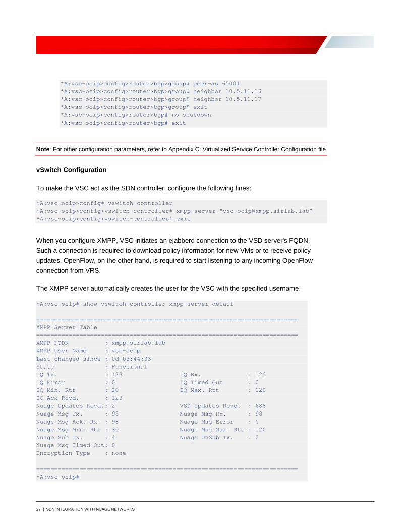
The XMPP server automatically creates the user for the VSC with the specified username.
*A:vsc-ocip# show vswitch-controller xmpp-server detail ========================================================================= XMPP Server Table ========================================================================= XMPP FQDN : xmpp.sirlab.lab XMPP User Name : vsc-ocip Last changed since : 0d 03:44:33 State : Functional IQ Tx. : 123 IQ Rx. : 123 IQ Error : 0 IQ Timed Out : 0 IQ Min. Rtt : 20 IQ Max. Rtt : 120 IQ Ack Rcvd. : 123 Nuage Updates Rcvd.: 2 VSD Updates Rcvd. : 688 Nuage Msg Tx. : 98 Nuage Msg Rx. : 98 Nuage Msg Ack. Rx. : 98 Nuage Msg Error : 0 Nuage Msg Min. Rtt : 30 Nuage Msg Max. Rtt : 120 Nuage Sub Tx. : 4 Nuage UnSub Tx. : 0 Nuage Msg Timed Out: 0 Encryption Type : none ========================================================================= *A:vsc-ocip#
28 | SDN INTEGRATION WITH NUAGE NETWORKS
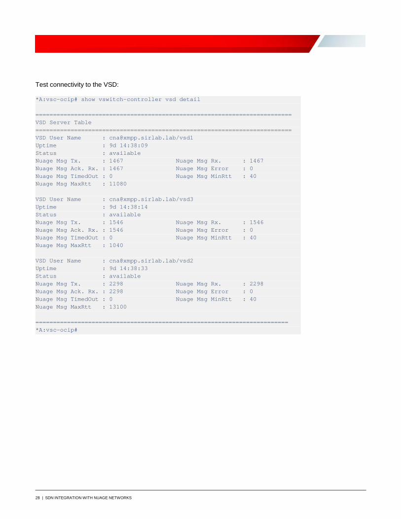
Test connectivity to the VSD:
*A:vsc-ocip# show vswitch-controller vsd detail ========================================================================= VSD Server Table ========================================================================= VSD User Name : [email protected]/vsd1 Uptime : 9d 14:38:09 Status : available Nuage Msg Tx. : 1467 Nuage Msg Rx. : 1467 Nuage Msg Ack. Rx. : 1467 Nuage Msg Error : 0 Nuage Msg TimedOut : 0 Nuage Msg MinRtt : 40 Nuage Msg MaxRtt : 11080 VSD User Name : [email protected]/vsd3 Uptime : 9d 14:38:14 Status : available Nuage Msg Tx. : 1546 Nuage Msg Rx. : 1546 Nuage Msg Ack. Rx. : 1546 Nuage Msg Error : 0 Nuage Msg TimedOut : 0 Nuage Msg MinRtt : 40 Nuage Msg MaxRtt : 1040 VSD User Name : [email protected]/vsd2 Uptime : 9d 14:38:33 Status : available Nuage Msg Tx. : 2298 Nuage Msg Rx. : 2298 Nuage Msg Ack. Rx. : 2298 Nuage Msg Error : 0 Nuage Msg TimedOut : 0 Nuage Msg MinRtt : 40 Nuage Msg MaxRtt : 13100 ======================================================================== *A:vsc-ocip#
29 | SDN INTEGRATION WITH NUAGE NETWORKS
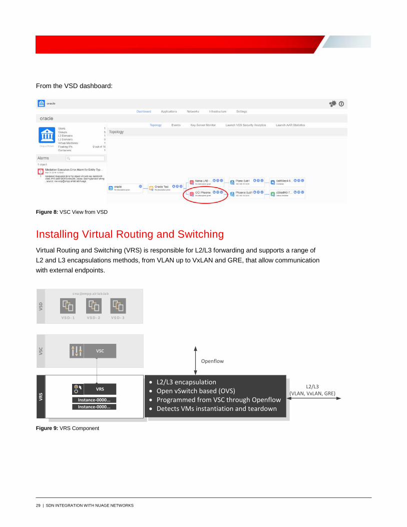
From the VSD dashboard:
Figure 8: VSC View from VSD
Installing Virtual Routing and Switching Virtual Routing and Switching (VRS) is responsible for L2/L3 forwarding and supports a range of L2 and L3 encapsulations methods, from VLAN up to VxLAN and GRE, that allow communication with external endpoints.
VS D - 1 VS D - 2
VSC
VRS
VSD
VRS
VSC
Instance-0000...Instance-0000...
VS D - 3
cna @xmpp.sir la b.la b
• L2/L3 encapsulation• Open vSwitch based (OVS)• Programmed from VSC through Openflow• Detects VMs instantiation and teardown
Openflow
L2/L3 (VLAN, VxLAN, GRE)
Figure 9: VRS Component
30 | SDN INTEGRATION WITH NUAGE NETWORKS
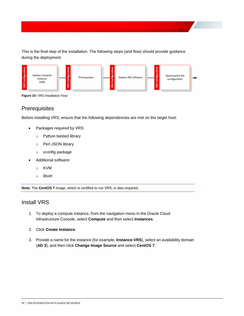
This is the final step of the installation. The following steps (and flow) should provide guidance during the deployment.
VRS
Conf
igur
atio
n
Deploy Compute Instance
(VM)
Deploy VRS softwarePrerequisites Openvswitch file configuration
VRS
Conf
igur
atio
n
VRS
Conf
igur
atio
n
VRS
Conf
igur
atio
n
Figure 10: VRS Installation Flow
Prerequisites Before installing VRS, ensure that the following dependencies are met on the target host:
• Packages required by VRS:
o Python twisted library
o Perl JSON library
o vconfig package
• Additional software:
o KVM
o libvirt
Note: The CentOS 7 image, which is certified to run VRS, is also required.
Install VRS
1. To deploy a compute instance, from the navigation menu in the Oracle Cloud Infrastructure Console, select Compute and then select Instances.
2. Click Create Instance.
3. Provide a name for the instance (for example, Instance-VRS), select an availability domain (AD 3), and then click Change Image Source and select CentOS 7.

31 | SDN INTEGRATION WITH NUAGE NETWORKS
4. Select Virtual Machine, click Change Shape, select VM.Standard2.2, and then click Select Shape.
5. In the Add SSH key section, select to choose an SSH key file or paste the SSH key in the text box.

32 | SDN INTEGRATION WITH NUAGE NETWORKS
6. In the Configure networking section, select the VCN's compartment, the VCN, the subnet's compartment, and the subnet (mgt-plain).
7. Click Create.
After some minutes, the instance is up and running, as shown in the image:
33 | SDN INTEGRATION WITH NUAGE NETWORKS
8. After the VM is up and running, log in to the instance and install or update the repos from the Prerequisites section: [root@instance-vrs opc]# yum install libvirt [root@instance-vrs opc]# yum install qemu-kvm
Warning: Always check the list of supported kernels in the Nuage Networks release notes. Any system update (yum update) can lead into an unsupported operating system version.
9. Check the kernel that is currently running: [root@instance-vrs opc]# uname -r 3.10.0-957.1.3.el7.x86_64
10. Each supported operating system has a VRS .tar.gz file. Copy the VRS software file to the destination host: [root@instance-vrs opc]# mkdir nuage [root@instance-vrs opc]# cd /home/opc/nuage [root@instance-vrs nuage]# scp admin@source_host :/share/nfs/nuage/5.3.3/nuage-VRS- 5.3.3-128.tar.gz ./ nuage-VRS- 5.3.3-128.tar.gz
11. Untar the Nuage VRS software file on the host: [root@instance-vrs nuage]# tar xzvf nuage-VRS- 5.3.3-128.tar.gz
12. Install the nuage-openvswitch package and the nuage-bgp package: [root@instance-vrs nuage]# yum localinstall nuage-openvswitch- 5.3.3-128.el7.x86_64.rpm [root@instance-vrs nuage]# yum localinstall nuage-bgp- 5.3.3-128.el7.x86_64.rpm
13. Verify that the package has been installed: [root@instance-vrs nuage]# yum list installed | grep nuage nuage-metadata-agent.x86_64 5.3.3-128.el7 installed nuage-openvswitch.x86_64 5.3.3-128.el7 installed
34 | SDN INTEGRATION WITH NUAGE NETWORKS
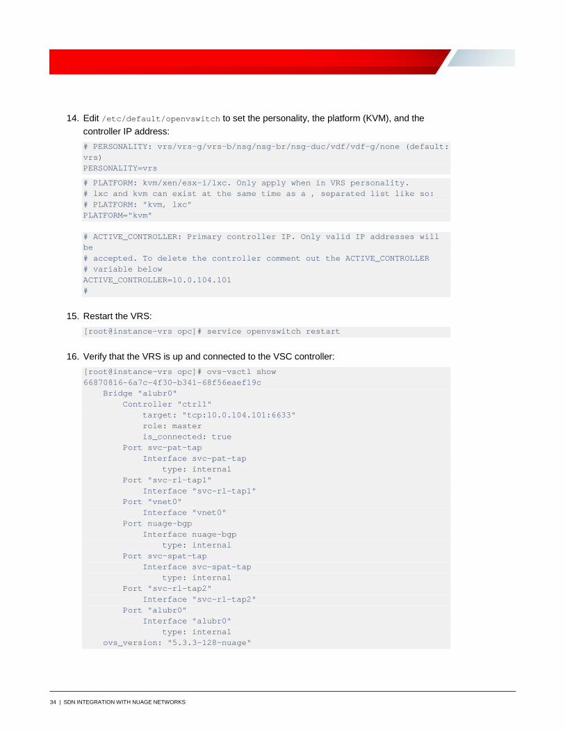
14. Edit /etc/default/openvswitch to set the personality, the platform (KVM), and the controller IP address: # PERSONALITY: vrs/vrs-g/vrs-b/nsg/nsg-br/nsg-duc/vdf/vdf-g/none (default: vrs) PERSONALITY=vrs
# PLATFORM: kvm/xen/esx-i/lxc. Only apply when in VRS personality. # lxc and kvm can exist at the same time as a , separated list like so: # PLATFORM: "kvm, lxc" PLATFORM="kvm" # ACTIVE_CONTROLLER: Primary controller IP. Only valid IP addresses will be # accepted. To delete the controller comment out the ACTIVE_CONTROLLER # variable below ACTIVE_CONTROLLER=10.0.104.101 #
15. Restart the VRS: [root@instance-vrs opc]# service openvswitch restart
16. Verify that the VRS is up and connected to the VSC controller: [root@instance-vrs opc]# ovs-vsctl show 66870816-6a7c-4f30-b341-68f56eaef19c Bridge "alubr0" Controller "ctrl1" target: "tcp:10.0.104.101:6633" role: master is_connected: true Port svc-pat-tap Interface svc-pat-tap type: internal Port "svc-rl-tap1" Interface "svc-rl-tap1" Port "vnet0" Interface "vnet0" Port nuage-bgp Interface nuage-bgp type: internal Port svc-spat-tap Interface svc-spat-tap type: internal Port "svc-rl-tap2" Interface "svc-rl-tap2" Port "alubr0" Interface "alubr0" type: internal ovs_version: "5.3.3-128-nuage"

35 | SDN INTEGRATION WITH NUAGE NETWORKS
other_config: {acl-non-tcp-timeout="180", acl-tcp-timeout="3600", connid-type="", connid-val="", connobj-limit="320000", control-cos="7", control-dscp="56", controller-less-duration="", "disable-dhcp4"=no, dual-vtep=no, flow-collection="true", flow-limit="200000", fp-ports="", head-less-duration="", nat-traversal-enabled=no, network-namespace=default, nw-uplink="ens4f0", openflow_audit_timer="180", personality=vrs, platform=kvm, revertive-controller=no, revertive-timer="300", stats-collector="10.5.0.11:39090,10.5.0.12:39090,10.5.0.13:39090", stats-collector-type=ip, stats-enable="true", sticky-ecmp-timeout="0", syslog-dest=localhost, syslog-dest-port="514", sysmon-timer="3600", tcp-mss="0", vdf_uplink="", vport-init-stateful-timer="300", vss-stats-interval="30"} [root@instance-vrs opc]#
17. Confirm connectivity from VSC to VRS: *A:vsc-ocip# show vswitch-controller vswitches ===================================================================== VSwitch Table ===================================================================== --------------------------------------------------------------------- Legend: * -> Primary Controller ! -> NSG in Graceful Restart --------------------------------------------------------------------- Vswitch-Instance Personality Uptime Num VM/Host/Bridge/Cont Num Resolved --------------------------------------------------------------------- *va-10.0.103.3/1 VRS 37d 21:08:39 1/0/0/0 1/0/0/0 --------------------------------------------------------------------- No. of virtual switches: 1 --------------------------------------------------------------------- ===================================================================== *A:vsc-ocip#
You can query VRS directly from VSCs by sending a specific shell command down the VRS, capturing the output, and displaying it on the controller.
18. List the VMs behind the VRS: *A:vsc-ocip# tools vswitch 10.0.103.3 command "ovs-appctl vm/show"
36 | SDN INTEGRATION WITH NUAGE NETWORKS
19. You can even check the routing table configured in the VRS: *A:vsc-ocip# tools vswitch 10.0.103.3 command "ovs-appctl vrf/list alubr0"
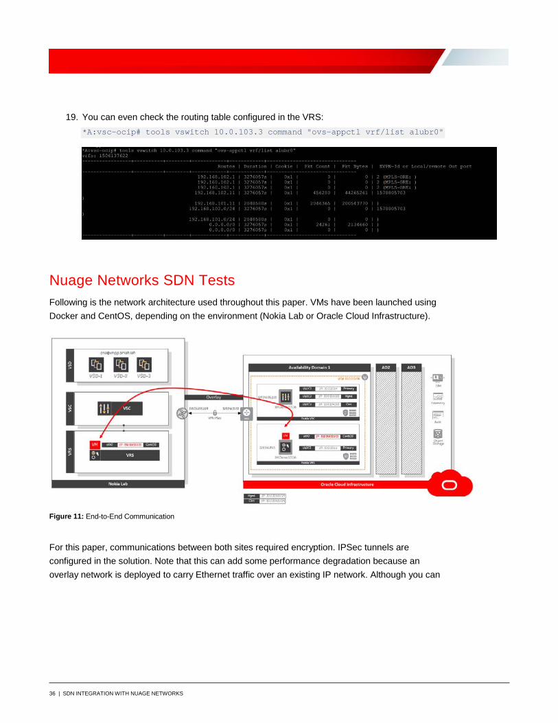
Nuage Networks SDN Tests Following is the network architecture used throughout this paper. VMs have been launched using Docker and CentOS, depending on the environment (Nokia Lab or Oracle Cloud Infrastructure).
Figure 11: End-to-End Communication
For this paper, communications between both sites required encryption. IPSec tunnels are configured in the solution. Note that this can add some performance degradation because an overlay network is deployed to carry Ethernet traffic over an existing IP network. Although you can

37 | SDN INTEGRATION WITH NUAGE NETWORKS
run connectivity between both sites without using IPSec tunnels, we strongly recommend securing communications.
Figure 12: Routing Tables
The following image shows CentOS VM network configuration in Oracle Cloud Infrastructure:
Figure 13: CentOS VM Network Configuration
38 | SDN INTEGRATION WITH NUAGE NETWORKS
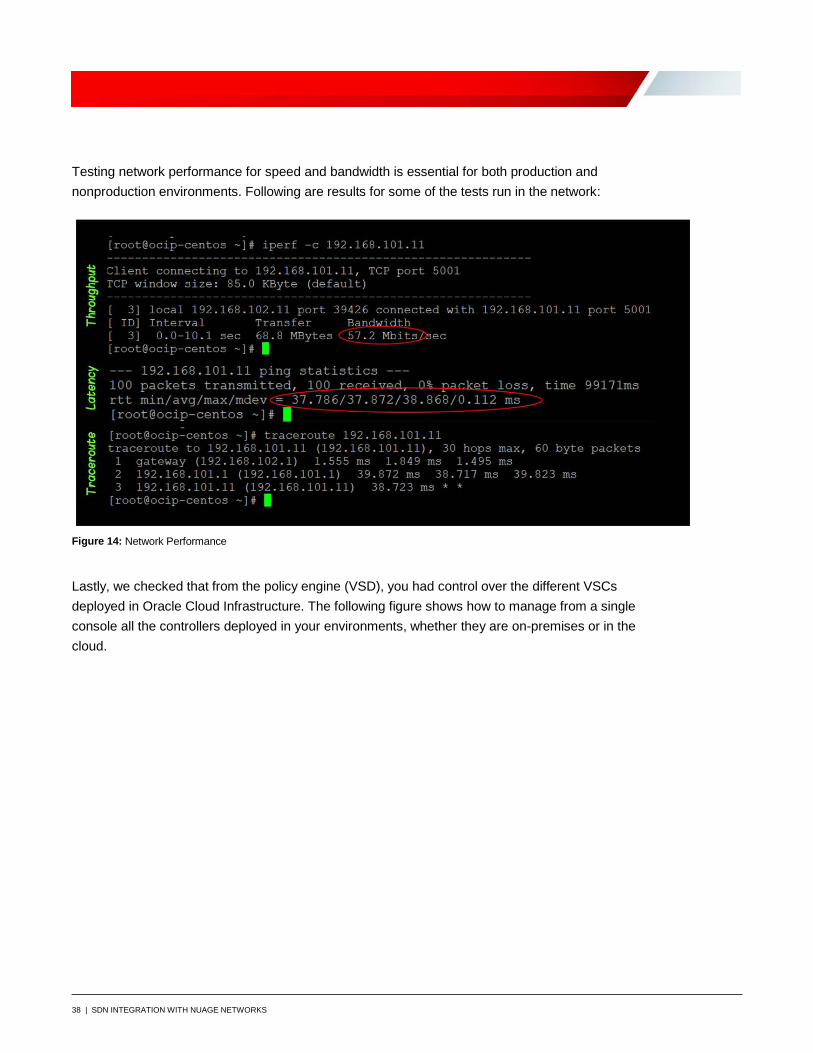
Testing network performance for speed and bandwidth is essential for both production and nonproduction environments. Following are results for some of the tests run in the network:
Figure 14: Network Performance
Lastly, we checked that from the policy engine (VSD), you had control over the different VSCs deployed in Oracle Cloud Infrastructure. The following figure shows how to manage from a single console all the controllers deployed in your environments, whether they are on-premises or in the cloud.

39 | SDN INTEGRATION WITH NUAGE NETWORKS
Figure 15: VSD Layer 3 Domain
Appendix A: Attach Secondary VNICs in Oracle Cloud Infrastructure You can add secondary VNICs by using the Oracle Cloud Infrastructure Console.
1. From the navigation menu, select Compute and then select Instances.
2. Click the name of the instance (in this case, Instance-VSC) to view its details.
3. Under Resources, click Attached VNICs.
4. Click Create VNIC.
5. Provide the following information:
• Name: vf-mgt-nic
• Virtual Cloud Network: VCN
• Subnet: mgt-plain
• Private IP Address: 10.0.103.101
Leave the rest of the entries blank.
40 | SDN INTEGRATION WITH NUAGE NETWORKS
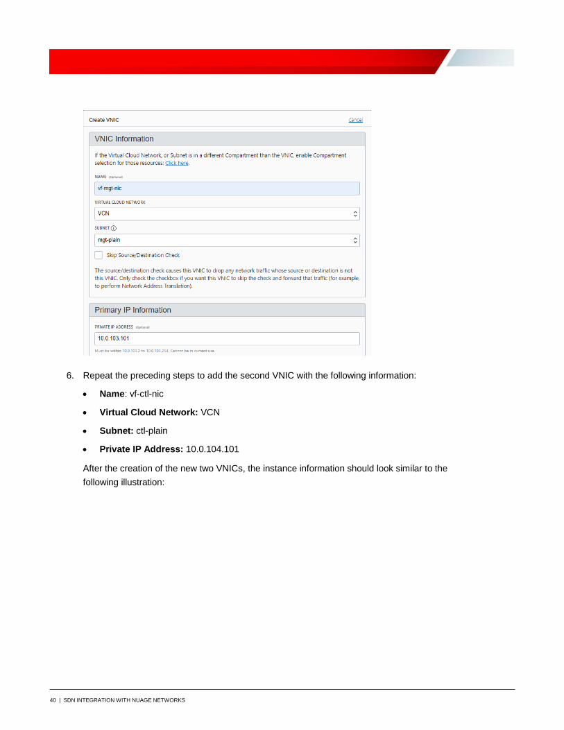
6. Repeat the preceding steps to add the second VNIC with the following information:
• Name: vf-ctl-nic
• Virtual Cloud Network: VCN
• Subnet: ctl-plain
• Private IP Address: 10.0.104.101
After the creation of the new two VNICs, the instance information should look similar to the following illustration:

41 | SDN INTEGRATION WITH NUAGE NETWORKS
7. Create a directory and download the secondary_vnic_all_configure.sh script. Connect to the instance by using SSH and run the following commands: mkdir /opt/secondary_vnic cd /opt/secondary_vnic wget https://docs.cloud.oracle.com/iaas/Content/Resources/Assets/secondary_vnic_all_configure.sh chmod u+x secondary_vnic_all_configure.sh
8. Create the unit file: # vi /etc/systemd/system/secondary_vnic_all_configure.service
9. Paste the following lines into the file: [Unit] Description=Add the secondary VNIC at boot After=basic.target [Service] Type=oneshot ExecStart=/opt/secondary_vnic/secondary_vnic_all_configure.sh -c [Install] WantedBy=default.target
10. Enable the unit file: # chmod 664 /etc/systemd/system/secondary_vnic_all_configure.service # systemctl enable /etc/systemd/system/secondary_vnic_all_configure.service # systemctl list-unit-files|egrep secondary_vnic_all_configure.service
11. Reboot the instance by clicking the Reboot button on the instance details page in the Oracle Cloud Infrastructure Console.

42 | SDN INTEGRATION WITH NUAGE NETWORKS
12. Confirm that the second VNIC is automatically configured: # uptime; ip address
Appendix B: Virtualized Services Controller BOF File *A:vsc-ocip# show bof ============================================================================= BOF (Memory) ============================================================================= primary-image cf1:\timos\cpm.tim primary-config cf1:\config.cfg address 10.0.103.101/24 active primary-dns 10.5.0.50 dns-domain sirlab.lab static-route 0.0.0.0/1 next-hop 10.0.103.1 static-route 128.0.0.0/1 next-hop 10.0.103.1 autonegotiate duplex full speed 100 wait 3 persist off no li-local-save no li-separate no fips-140-2 console-speed 115200 ============================================================================= *A:vsc-ocip#
Appendix C: Virtualized Services Controller Configuration File For the main configuration, type admin display-config.
*A:vsc-ocip# admin display-config # TiMOS-DC-C-5.3.3-100 cpm/i386 NUAGE VSC Copyright (c) 2000-2018 Nokia. # All rights reserved. All use subject to applicable license agreements. # Built on Wed Oct 31 13:42:50 PDT 2018 [d429da] by builder in /rel5.3-DC/release/panos/main # Generated MON MAR 11 13:40:49 2019 UTC exit all configure #-------------------------------------------------- echo "System Configuration" #-------------------------------------------------- name "vsc-ocip"
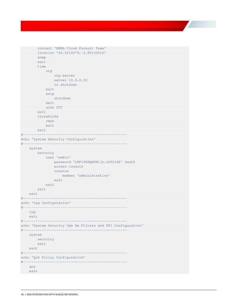
43 | SDN INTEGRATION WITH NUAGE NETWORKS
contact "EMEA Cloud Pursuit Team" location "40.5214579,-3.8913381b" snmp exit time ntp ntp-server server 10.5.0.50 no shutdown exit sntp shutdown exit zone UTC exit thresholds rmon exit exit #-------------------------------------------------- echo "System Security Configuration" #-------------------------------------------------- system security user "admin" password "L8PI6XXQN0W1jz.nZ92v2E" hash2 access console console member "administrative" exit exit exit exit #-------------------------------------------------- echo "Log Configuration" #-------------------------------------------------- log exit #-------------------------------------------------- echo "System Security Cpm Hw Filters and PKI Configuration" #-------------------------------------------------- system security exit exit #-------------------------------------------------- echo "QoS Policy Configuration" #-------------------------------------------------- qos exit
44 | SDN INTEGRATION WITH NUAGE NETWORKS
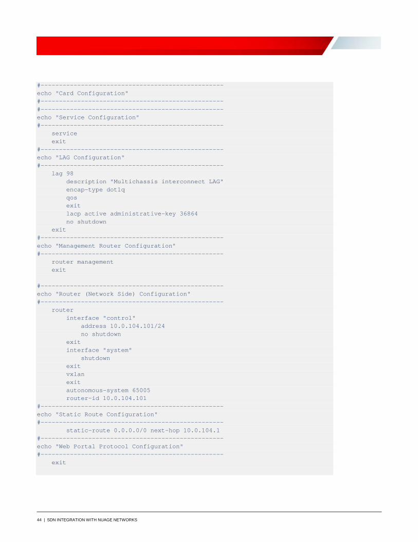
#-------------------------------------------------- echo "Card Configuration" #-------------------------------------------------- #-------------------------------------------------- echo "Service Configuration" #-------------------------------------------------- service exit #-------------------------------------------------- echo "LAG Configuration" #-------------------------------------------------- lag 98 description "Multichassis interconnect LAG" encap-type dot1q qos exit lacp active administrative-key 36864 no shutdown exit #-------------------------------------------------- echo "Management Router Configuration" #-------------------------------------------------- router management exit #-------------------------------------------------- echo "Router (Network Side) Configuration" #-------------------------------------------------- router interface "control" address 10.0.104.101/24 no shutdown exit interface "system" shutdown exit vxlan exit autonomous-system 65005 router-id 10.0.104.101 #-------------------------------------------------- echo "Static Route Configuration" #-------------------------------------------------- static-route 0.0.0.0/0 next-hop 10.0.104.1 #-------------------------------------------------- echo "Web Portal Protocol Configuration" #-------------------------------------------------- exit

45 | SDN INTEGRATION WITH NUAGE NETWORKS
#-------------------------------------------------- echo "Service Configuration" #-------------------------------------------------- service customer 1 create description "Default customer" exit exit #-------------------------------------------------- echo "Router (Service Side) Configuration" #-------------------------------------------------- router #-------------------------------------------------- echo "BGP Configuration" #-------------------------------------------------- bgp connect-retry 2 enable-peer-tracking rapid-withdrawal rapid-update evpn group "myvscs" family evpn type external multihop 5 peer-as 65001 neighbor 10.5.11.16 exit neighbor 10.5.11.17 exit exit no shutdown exit exit #-------------------------------------------------- echo "System Time NTP Configuration" #-------------------------------------------------- system time ntp exit exit exit #-------------------------------------------------- echo "Virtual Switch Controller Configuration" #-------------------------------------------------- vswitch-controller xmpp-server "[email protected]" open-flow exit xmpp
46 | SDN INTEGRATION WITH NUAGE NETWORKS
exit ovsdb exit init exit exit exit all # Finished MON MAR 11 13:41:04 2019 UTC *A:vsc-ocip#
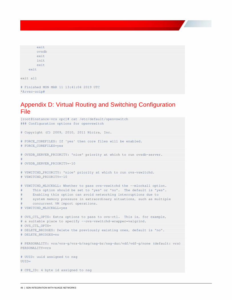
Appendix D: Virtual Routing and Switching Configuration File [root@instance-vrs opc]# cat /etc/default/openvswitch ### Configuration options for openvswitch # Copyright (C) 2009, 2010, 2011 Nicira, Inc. # FORCE_COREFILES: If 'yes' then core files will be enabled. # FORCE_COREFILES=yes # OVSDB_SERVER_PRIORITY: "nice" priority at which to run ovsdb-server. # # OVSDB_SERVER_PRIORITY=-10 # VSWITCHD_PRIORITY: "nice" priority at which to run ovs-vswitchd. # VSWITCHD_PRIORITY=-10 # VSWITCHD_MLOCKALL: Whether to pass ovs-vswitchd the --mlockall option. # This option should be set to "yes" or "no". The default is "yes". # Enabling this option can avoid networking interruptions due to # system memory pressure in extraordinary situations, such as multiple # concurrent VM import operations. # VSWITCHD_MLOCKALL=yes # OVS_CTL_OPTS: Extra options to pass to ovs-ctl. This is, for example, # a suitable place to specify --ovs-vswitchd-wrapper=valgrind. # OVS_CTL_OPTS= # DELETE_BRIDGES: Delete the previously existing ones, default is "no". # DELETE_BRIDGES=no # PERSONALITY: vrs/vrs-g/vrs-b/nsg/nsg-br/nsg-duc/vdf/vdf-g/none (default: vrs) PERSONALITY=vrs # UUID: uuid assigned to nsg UUID= # CPE_ID: 4 byte id assigned to nsg

47 | SDN INTEGRATION WITH NUAGE NETWORKS
CPE_ID= # DATAPATH_ID: Datapath id of the nsg DATAPATH_ID= # UPLINK_ID: uplink id assigned to nsg UPLINK_ID= # NETWORK_UPLINK_INTF: uplink interface of the host NETWORK_UPLINK_INTF=ens4f0 # NETWORK_NAMESPACE: namespace to create pat interfaces, iptables & route rules NETWORK_NAMESPACE= # VDF_UPLINK: Adds intf to use as uplink for vdf for creating vlan interfaces VDF_UPLINK= # # VRSG_PEER_IP: Applies only when in GateWay mode # VRSG_PEER_IP=0.0.0.0 # PLATFORM: kvm/xen/esx-i/lxc. Only apply when in VRS personality. # lxc and kvm can exist at the same time as a , separated list like so: # PLATFORM: "kvm, lxc" PLATFORM="kvm" # DEFAULT_BRIDGE: Nuage managed bridge DEFAULT_BRIDGE=alubr0 # BRIDGE_MTU: Configurable bridge MTU #BRIDGE_MTU= # MCAST_UNDERLAY_TX_INTF: mcast tx interface #MCAST_UNDERLAY_TX_INTF= # GW_HB_BRIDGE: Name of the gateway heartbeat bridge GW_HB_BRIDGE= # GW_HB_VLAN: vlan for heart beat exchange in gateways GW_HB_VLAN= # GW_HB_TIMEOUT: timeout for heart beat exchange in gateways in milliseconds GW_HB_TIMEOUT=2000 # MGMT_ETH: Comma separated names of management Ethernet interfaces MGMT_ETH= # UPLINK_ETH: Comma separated names of Ethernet interfaces used for uplink UPLINK_ETH= # GW_PEER_DATAPATH_ID: Datapath ID of peer gateway to which access resiliency # will be established
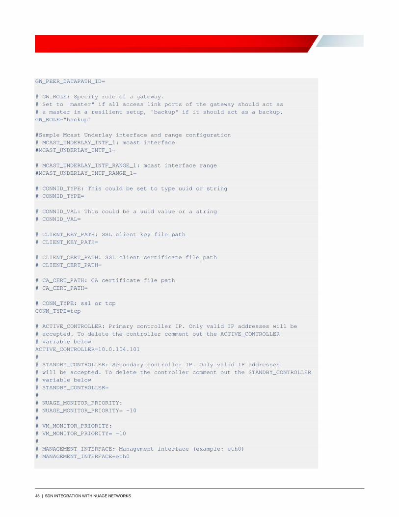
48 | SDN INTEGRATION WITH NUAGE NETWORKS
GW_PEER_DATAPATH_ID= # GW_ROLE: Specify role of a gateway. # Set to "master" if all access link ports of the gateway should act as # a master in a resilient setup, "backup" if it should act as a backup. GW_ROLE="backup" #Sample Mcast Underlay interface and range configuration # MCAST_UNDERLAY_INTF_1: mcast interface #MCAST_UNDERLAY_INTF_1= # MCAST_UNDERLAY_INTF_RANGE_1: mcast interface range #MCAST_UNDERLAY_INTF_RANGE_1= # CONNID_TYPE: This could be set to type uuid or string # CONNID_TYPE= # CONNID_VAL: This could be a uuid value or a string # CONNID_VAL= # CLIENT_KEY_PATH: SSL client key file path # CLIENT_KEY_PATH= # CLIENT_CERT_PATH: SSL client certificate file path # CLIENT_CERT_PATH= # CA_CERT_PATH: CA certificate file path # CA_CERT_PATH= # CONN_TYPE: ssl or tcp CONN_TYPE=tcp # ACTIVE_CONTROLLER: Primary controller IP. Only valid IP addresses will be # accepted. To delete the controller comment out the ACTIVE_CONTROLLER # variable below ACTIVE_CONTROLLER=10.0.104.101 # # STANDBY_CONTROLLER: Secondary controller IP. Only valid IP addresses # will be accepted. To delete the controller comment out the STANDBY_CONTROLLER # variable below # STANDBY_CONTROLLER= # # NUAGE_MONITOR_PRIORITY: # NUAGE_MONITOR_PRIORITY= -10 # # VM_MONITOR_PRIORITY: # VM_MONITOR_PRIORITY= -10 # # MANAGEMENT_INTERFACE: Management interface (example: eth0) # MANAGEMENT_INTERFACE=eth0
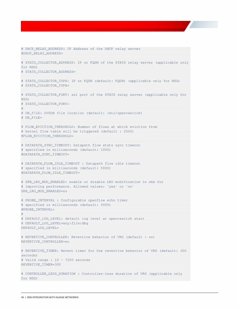
49 | SDN INTEGRATION WITH NUAGE NETWORKS
# DHCP_RELAY_ADDRESS: IP Address of the DHCP relay server #DHCP_RELAY_ADDRESS= # STATS_COLLECTOR_ADDRESS: IP or FQDN of the STATS relay server (applicable only for NSG) # STATS_COLLECTOR_ADDRESS= # STATS_COLLECTOR_TYPE: IP or FQDN (default: FQDN) (applicable only for NSG) # STATS_COLLECTOR_TYPE= # STATS_COLLECTOR_PORT: ssl port of the STATS relay server (applicable only for NSG) # STATS_COLLECTOR_PORT= # # DB_FILE: OVSDB file location (default: /etc/openvswitch) # DB_FILE= # FLOW_EVICTION_THRESHOLD: Number of flows at which eviction from # kernel flow table will be triggered (default : 2500) #FLOW_EVICTION_THRESHOLD= # DATAPATH_SYNC_TIMEOUT: Datapath flow stats sync timeout # specified in milliseconds (default: 1000) #DATAPATH_SYNC_TIMEOUT= # DATAPATH_FLOW_IDLE_TIMEOUT : Datapath flow idle timeout # specified in milliseconds (default: 5000) #DATAPATH_FLOW_IDLE_TIMEOUT= # SKB_LRO_MOD_ENABLED: enable or disable LRO modification in skb for # improving performance. Allowed values: 'yes' or 'no' SKB_LRO_MOD_ENABLED=no # PROBE_INTERVAL : Configurable openflow echo timer # specified in milliseconds (default: 5000) #PROBE_INTERVAL= # # DEFAULT_LOG_LEVEL: default log level at openvswitch start # DEFAULT_LOG_LEVEL=any:file:dbg DEFAULT_LOG_LEVEL= # REVERTIVE_CONTROLLER: Revertive behavior of VRS (default : no) REVERTIVE_CONTROLLER=no # REVERTIVE_TIMER: Revert timer for the revertive behavior of VRS (default: 300 seconds) # Valid range : 10 - 7200 seconds REVERTIVE_TIMER=300 # CONTROLLER_LESS_DURATION : Controller-less duration of VRS (applicable only for NSG)

50 | SDN INTEGRATION WITH NUAGE NETWORKS
# (default is 3600 seconds. Valid Range: 3600 seconds(1 hr) - 86400 seconds(24 hr)) # -1 indicates infinite duration #CONTROLLER_LESS_DURATION=3600 # Service IPV4 subnet for kubernetes K8S_SERVICE_IPV4_SUBNET=0.0.0.0/8 # Pod IPV4 subnet for kubernetes K8S_POD_NETWORK_CIDR=0.0.0.0/8 # FP_PORTS: List of fast-path ports to be recognized as Network ports (applicable only for Advanced VRS) #FP_PORTS= # DUAL_VTEP_VRS: VRS supports dual-uplinks (default:no) (applicable only for DC environments) #DUAL_VTEP_VRS= # DISABLE_DHCP4: VRS will not act as dhcp server (default:no) (applicable only # for DC environments) #DISABLE_DHCP4= # UPLINK1: Uplink 1 name (applicable only when DUAL_VTEP_VRS is enabled) #UPLINK1= # Controller configuration (applicable only when DUAL_VTEP_VRS is enabled) # UPLINK1_ACTIVE_CONTROLLER: Active controller of Uplink 1 (applicable only when DUAL_VTEP_VRS is enabled) #UPLINK1_ACTIVE_CONTROLLER= # UPLINK1_STANDBY_CONTROLLER: Standby controller of Uplink 1 (applicable only when DUAL_VTEP_VRS is enabled) #UPLINK1_STANDBY_CONTROLLER= # UPLINK1_UNDERLAY_ID: Underlay ID of Uplink 1 (applicable only when DUAL_VTEP_VRS is enabled) #UPLINK1_UNDERLAY_ID= # UPLINK2: Uplink 2 name (applicable only when DUAL_VTEP_VRS is enabled) #UPLINK2= # UPLINK2_ACTIVE_CONTROLLER: Active controller of Uplink 2 (applicable only when DUAL_VTEP_VRS is enabled) #UPLINK2_ACTIVE_CONTROLLER= # UPLINK2_STANDBY_CONTROLLER: Standby controller of Uplink 2 (applicable only when DUAL_VTEP_VRS is enabled) #UPLINK2_STANDBY_CONTROLLER= # UPLINK2_UNDERLAY_ID: Underlay ID of Uplink 2 (applicable only when DUAL_VTEP_VRS is enabled)
51 | SDN INTEGRATION WITH NUAGE NETWORKS
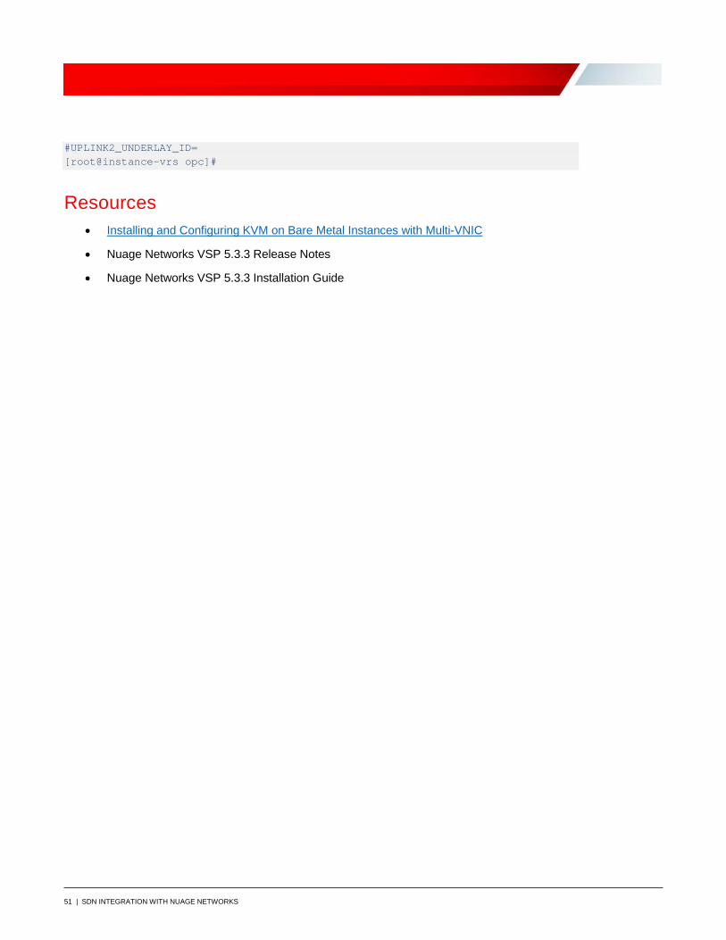
#UPLINK2_UNDERLAY_ID= [root@instance-vrs opc]#
Resources • Installing and Configuring KVM on Bare Metal Instances with Multi-VNIC
• Nuage Networks VSP 5.3.3 Release Notes
• Nuage Networks VSP 5.3.3 Installation Guide
Oracle Corporation, World Headquarters Worldwide Inquiries 500 Oracle Parkway Phone: +1.650.506.7000 Redwood Shores, CA 94065, USA Fax: +1.650.506.7200
Copyright © 2019, Oracle and/or its affiliates. All rights reserved. This document is provided for information purposes only, and the contents hereof are subject to change without notice. This document is not warranted to be error-free, nor subject to any other warranties or conditions, whether expressed orally or implied in law, including implied warranties and conditions of merchantability or fitness for a particular purpose. We specifically disclaim any liability with respect to this document, and no contractual obligations are formed either directly or indirectly by this document. This document may not be reproduced or transmitted in any form or by any means, electronic or mechanical, for any purpose, without our prior written permission. Oracle and Java are registered trademarks of Oracle and/or its affiliates. Other names may be trademarks of their respective owners. Intel and Intel Xeon are trademarks or registered trademarks of Intel Corporation. All SPARC trademarks are used under license and are trademarks or registered trademarks of SPARC International, Inc. AMD, Opteron, the AMD logo, and the AMD Opteron logo are trademarks or registered trademarks of Advanced Micro Devices. UNIX is a registered trademark of The Open Group. 0419 SDN Integration with Nuage Networks April 2019 Author: Oracle Corporation
C O N N E C T W I T H U S
blogs.oracle.com/oracle
facebook.com/oracle
twitter.com/oracle
oracle.com