Embed Size (px)
Citation preview

Scroll Tankmount/Basemount Air CompressorsPlease read and save these instructions. Read carefully before attempting to assemble, install, operate or maintain the product described. Protect yourself and others by observing all safety information. Failure to comply with instructions could result in personal injury and/or property damage! Retain instructions for future reference.
Description
Powerex • 150 Production Drive • Harrison, OH 45030 • USAP 1.888.769.7979 • F 513.367.3125 • www.powerexinc.com
IN258911AV • 09/2016Page 1 of 20
GeneralThe Powerex Oilless Rotary Scroll Air Compressor has advanced scroll
compressor technology through the development of a completely oilless unit. The Powerex Scroll Compressor offers a dynamically balanced air end which insures vibration-free operation. The rotary design permits a continuous 100% duty cycle. No oil separation, oil fi ltration, or inlet valves are required on the Powerex Scroll unit.
Compressor CycleThe Powerex oilless rotary scroll air compressor is based on
the theory of scroll compression. A scroll is a free standing, intricate spiral bounded on one side by a solid, fl at plane or base. A scroll set, the basic compression element of a scroll compressor, is made up of two identical spirals which form right and left hand parts. One of these scroll components is indexed or phased 180° with respect to the other so the scrolls can mesh. Crescent-shaped gas pockets are formed and bounded by the spirals and the base plate of both scrolls. As the moving scroll is orbited around the fi xed scroll, the pockets formed by the meshed scrolls follow the spiral toward the center and diminish in size. The moving scroll is prevented from rotating during this process so the 180° phase relationship of the scrolls is maintained. The compressor’s inlet is at the outer boundary of the scrolls. The compressed gas is discharged through the outlet at the center of the fi xed scroll so no valves are needed.
Tip SealThe tip seal on the scroll compressor is self-lubricated
and allows the unit to operate efficiently without oil and expensive fi ltration. On standard pressure units, the tip seal should be replaced every 10,000 hours of operation. On high pressure units, the tip seal should be replaced every 5,000 hours of operation.
BearingsThe bearings on the scroll compressor are regreaseable to allow
extended compressor life. For standard pressure units, service should be performed every 10,000 hours of operation. For high pressure units, service should be performed every 5,000 hours of operation.
Dry Type Inlet Filter (P/N ST073925AV)Order element P/N ST073921AV for both the 3 HP and 5HP units.
Change every 2,500 hours or more often in dirty locations.
SPECIFICATIONS
Product STS, STD, SBS Scroll or STSH, STDH, SBSH High Pressure Scroll Tankmount/Basemount Air Compressors
Performance Specifications See Page 2
CA Ordinance 462(L)(2) Tankmount units meet the requirements of this ordinance
Compression Cycle Scroll
Control Panel UL508A Listed (panels are optional)
Drive 2 - 3V Belts
Lubrication Grease fi lled bearings
Motor Overload Protection IEC Motor overload relay (optional)
Operating Temperature 34° F - 104° F (1° C thru 40° C) at inlet
Operating Voltages 1Ø 280-230 Volts, 60 Hz3Ø 208-320/460 Volts, 60 Hz
Outlet Air Connections 1/2 inch Basemount3/4 inch NPT Tankmount
Overpressure Protection ASME safety valve factory set andsealed
Standard Pressure Settings Simplex: 95-115 psiDuplex: 90-110 psi; 95-115 psi
High Pressure Settings Simplex: 115-145 psiDuplex: 110-140 psi; 115-145 psi
Tank Isolation Standard tank mount units
Tank Size (Tankmount Units) Simplex Units: 30 and 60 gallonASME Rated 200 psigDuplex Units: 80 and 120 gallonASME Rated 200 psig
Figure 1: SBS Scroll Basemount Simplex

Scroll Tankmount/Basemount Air Compressors
Powerex • 150 Production Drive • Harrison, OH 45030 • USAP 1.888.769.7979 • F 513.367.3125 • www.powerexinc.com
IN258911AV • 09/2016Page 2 of 20
Model HP Phase SCFM @ 100 psig SCFM @ 145 psig Voltage Tank Size (gal)
Scroll Basemount SimplexModel SBS
SBS0307 3 3 8.8 7.1 208-230/460115/230
Basemount
SBS1307 3 1 8.8 7.1 Basemount
SBS0507 5 3 15.2 12.5 208-230/460208-230
Basemount
SBS1517 5 1 15.2 12.5 Basemount
Scroll Tankmount SimplexModel STS
STS030 3 3 8.8 7.1 208-230/460115/230
30/60
STS130 3 1 8.8 7.1 30/60
STS050 5 3 15.2 12.5 208-230/460208-230
30/60
STS151 5 1 15.2 12.5 30/60
Scroll Tankmount DuplexModel STD
STD030 3 (2) 3 17.6 14.2 208-230/460115/230
80
STD130 3 (2) 1 17.6 14.2 80
STD050 5 (2) 3 30.4 25.0 208-230/460208-230
80/120
STD150 5 (2) 1 30.4 25.0 80/120
Performance Specifications
NOTE: All high pressure models have an “H” at the end of the model identifi cation. These units are measured at 145 psig.
NOTE: For system electrical information (including motor FLA ratings), see the wiring diagram shipped with the unit.
Figure 2: Standard Model configuration and optional equipment
Mod
el S
BSM
odel
STS
Mod
el S
TD
Mod
el S
TS w
ith
optio
nal e
quip
men
tM
odel
STD
with
op
tiona
l equ
ipm
ent
Refrigerated Air Dryer Option
Refrigerated Air Dryer Option
Scroll Tankmount/Basemount Air Compressors
Powerex • 150 Production Drive • Harrison, OH 45030 • USAP 1.888.769.7979 • F 513.367.3125 • www.powerexinc.com
IN258911AV • 09/2016Page 3 of 20
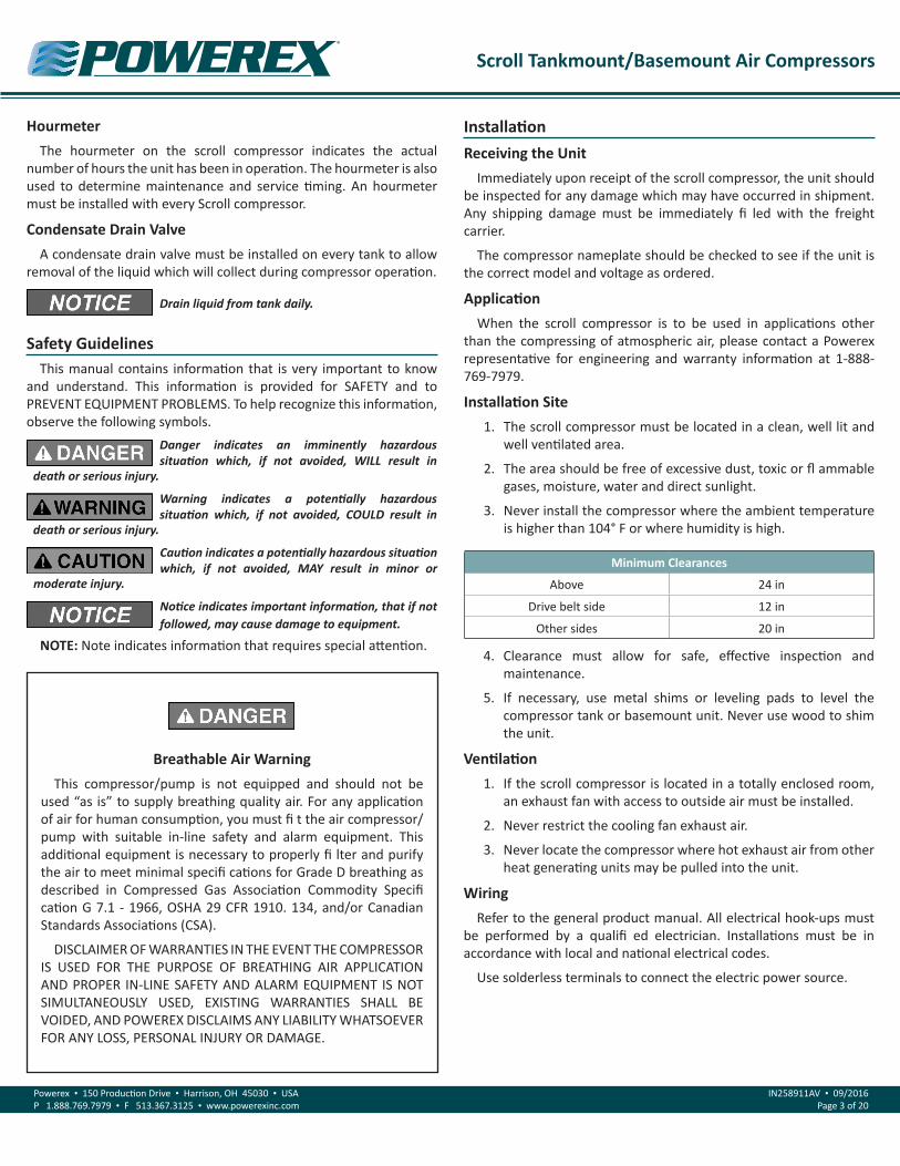
HourmeterThe hourmeter on the scroll compressor indicates the actual
number of hours the unit has been in operation. The hourmeter is also used to determine maintenance and service timing. An hourmeter must be installed with every Scroll compressor.
Condensate Drain ValveA condensate drain valve must be installed on every tank to allow
removal of the liquid which will collect during compressor operation.
Safety GuidelinesThis manual contains information that is very important to know
and understand. This information is provided for SAFETY and to PREVENT EQUIPMENT PROBLEMS. To help recognize this information, observe the following symbols.
Danger indicates an imminently hazardous situation which, if not avoided, WILL result in
death or serious injury.
Warning indicates a potentially hazardous situation which, if not avoided, COULD result in
death or serious injury.
Caution indicates a potentially hazardous situation which, if not avoided, MAY result in minor or
moderate injury.
Notice indicates important information, that if not followed, may cause damage to equipment.
NOTE: Note indicates information that requires special attention.
Drain liquid from tank daily.
Breathable Air WarningThis compressor/pump is not equipped and should not be
used “as is” to supply breathing quality air. For any application of air for human consumption, you must fi t the air compressor/pump with suitable in-line safety and alarm equipment. This additional equipment is necessary to properly fi lter and purify the air to meet minimal specifi cations for Grade D breathing as described in Compressed Gas Association Commodity Specifi cation G 7.1 - 1966, OSHA 29 CFR 1910. 134, and/or Canadian Standards Associations (CSA).
DISCLAIMER OF WARRANTIES IN THE EVENT THE COMPRESSOR IS USED FOR THE PURPOSE OF BREATHING AIR APPLICATION AND PROPER IN-LINE SAFETY AND ALARM EQUIPMENT IS NOT SIMULTANEOUSLY USED, EXISTING WARRANTIES SHALL BE VOIDED, AND POWEREX DISCLAIMS ANY LIABILITY WHATSOEVER FOR ANY LOSS, PERSONAL INJURY OR DAMAGE.
InstallationReceiving the Unit
Immediately upon receipt of the scroll compressor, the unit should be inspected for any damage which may have occurred in shipment. Any shipping damage must be immediately fi led with the freight carrier.
The compressor nameplate should be checked to see if the unit is the correct model and voltage as ordered.
ApplicationWhen the scroll compressor is to be used in applications other
than the compressing of atmospheric air, please contact a Powerex representative for engineering and warranty information at 1-888-769-7979.
Installation Site1. The scroll compressor must be located in a clean, well lit and
well ventilated area.
2. The area should be free of excessive dust, toxic or fl ammable gases, moisture, water and direct sunlight.
3. Never install the compressor where the ambient temperature is higher than 104° F or where humidity is high.
Minimum Clearances
Above 24 in
Drive belt side 12 in
Other sides 20 in
4. Clearance must allow for safe, effective inspection and maintenance.
5. If necessary, use metal shims or leveling pads to level the compressor tank or basemount unit. Never use wood to shim the unit.
Ventilation1. If the scroll compressor is located in a totally enclosed room,
an exhaust fan with access to outside air must be installed.
2. Never restrict the cooling fan exhaust air.
3. Never locate the compressor where hot exhaust air from other heat generating units may be pulled into the unit.
WiringRefer to the general product manual. All electrical hook-ups must
be performed by a qualifi ed electrician. Installations must be in accordance with local and national electrical codes.
Use solderless terminals to connect the electric power source.
Scroll Tankmount/Basemount Air Compressors
Powerex • 150 Production Drive • Harrison, OH 45030 • USAP 1.888.769.7979 • F 513.367.3125 • www.powerexinc.com
IN258911AV • 09/2016Page 4 of 20
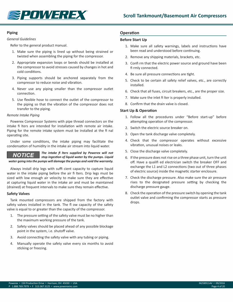
PipingGeneral Guidelines
Refer to the general product manual.
1. Make sure the piping is lined up without being strained or twisted when assembling the piping for the compressor.
2. Appropriate expansion loops or bends should be installed at the compressor to avoid stresses caused by changes in hot and cold conditions.
3. Piping supports should be anchored separately from the compressor to reduce noise and vibration.
4. Never use any piping smaller than the compressor outlet connection.
5. Use flexible hose to connect the outlet of the compressor to the piping so that the vibration of the compressor does not transfer to the piping.
Remote Intake Piping
Powerex Compressor Systems with pipe thread connectors on the intake fi lters are intended for installation with remote air intake. Piping for the remote intake system must be installed at the fi nal operating site.
Under some conditions, the intake piping may facilitate the condensation of humidity in the intake air stream into liquid water.
The intake fi lters supplied by Powerex will not stop ingestion of liquid water by the pumps. Liquid
water going into the pumps will damage the pumps and void the warranty.
Always install drip legs with suffi cient capacity to capture liquid water in the intake piping before the air fi lters. Drip legs must be sized with low enough air velocity to make sure they are effective at capturing liquid water in the intake air and must be maintained (drained) at frequent intervals to make sure they remain effective.
Safety ValvesTank mounted compressors are shipped from the factory with
safety valves installed in the tank. The fl ow capacity of the safety valve is equal to or greater than the capacity of the compressor.
1. The pressure setting of the safety valve must be no higher than the maximum working pressure of the tank.
2. Safety valves should be placed ahead of any possible blockage point in the system, i.e. shutoff valve.
3. Avoid connecting the safety valve with any tubing or piping.
4. Manually operate the safety valve every six months to avoid sticking or freezing.
OperationBefore Start Up
1. Make sure all safety warnings, labels and instructions have been read and understood before continuing.
2. Remove any shipping materials, brackets, etc.
3. Confi rm that the electric power source and ground have been fi rmly connected.
4. Be sure all pressure connections are tight.
5. Check to be certain all safety relief valves, etc., are correctly installed.
6. Check that all fuses, circuit breakers, etc., are the proper size.
7. Make sure the inlet fi lter is properly installed.
8. Confirm that the drain valve is closed.
Start Up & Operation1. Follow all the procedures under “Before start-up” before
attempting operation of the compressor.
2. Switch the electric source breaker on.
3. Open the tank discharge valve completely.
4. Check that the compressor operates without excessive vibration, unusual noises or leaks.
5. Close the discharge valve completely.
6. If the pressure does not rise on a three phase unit, turn the unit off. Have a qualifi ed electrician switch the breaker OFF and exchange the L1 and L2 connections (two out of three phases of electric source) inside the magnetic starter enclosure.
7. Check the discharge pressure. Also make sure the air pressure rises to the designated pressure setting by checking the discharge pressure gauge.
8. Check the operation of the pressure switch by opening the tank outlet valve and confirming the compressor starts as pressure drops.
Scroll Tankmount/Basemount Air Compressors
Powerex • 150 Production Drive • Harrison, OH 45030 • USAP 1.888.769.7979 • F 513.367.3125 • www.powerexinc.com
IN258911AV • 09/2016Page 5 of 20
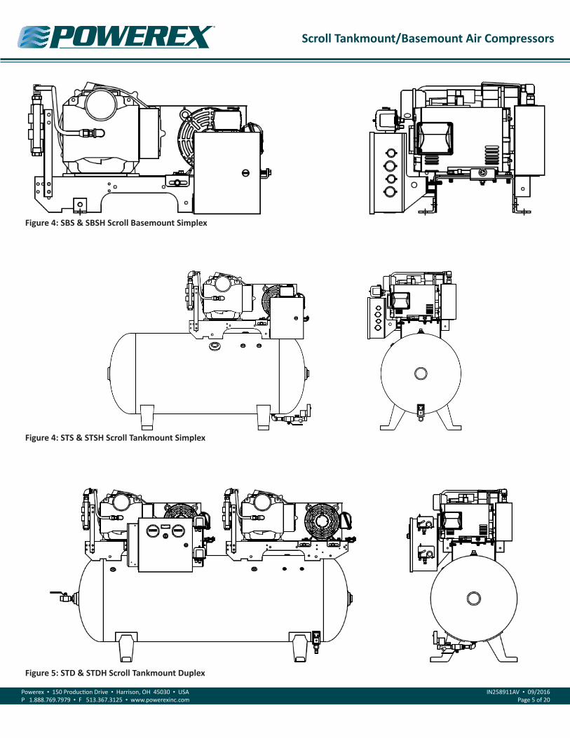
Figure 5: STD & STDH Scroll Tankmount Duplex
Figure 4: STS & STSH Scroll Tankmount Simplex
Figure 4: SBS & SBSH Scroll Basemount Simplex

Scroll Tankmount/Basemount Air Compressors
Powerex • 150 Production Drive • Harrison, OH 45030 • USAP 1.888.769.7979 • F 513.367.3125 • www.powerexinc.com
IN258911AV • 09/2016Page 6 of 20
Item Action NeededOperating Hours
Remarks500 2,500 5,000 10,000 15,000 20,000 30,000
Pump Replace ▲
Tank Drain moisture Daily
Inlet Air Filter InspectReplace ● ▲ (Every 2,500 hours or less) Element part #
ST073921AV
Blower Fan Clean ● ●
Fan Duct Clean ● ●
Compressor Fins Clean ● (Every 2,500 hours or less)
Bearings Grease ▲ ▲ Service Center only
Bearings* Grease ▲ ▲ ▲ ▲ Service Center only
Tip Seal Replace ▲ ▲ ▲ Every 10,000 hours
Tip Seal* Replace ▲ ▲ ▲ ▲ Every 5,000 hours
Heat insulation pipe Replace ▲ ▲ ▲ Every 10,000 hours
Heat insulation pipe Replace ▲ ▲ ▲ ▲ ▲ Every 5,000 hours
V-Belt InspectReplace Note 3 ● ▲ ▲ ▲ ▲ ▲
Pressure Switch Confirm operation ● ●
Magnetic Starter Inspect ● ● Replace if contact points deteriorated
Safety Valve Confirm operation ● (Every 2,500 hours or every 6 months, whichever comes first)
Pressure Gauge Inspect ● (Every 2,500 hours or less)
LEGEND ● Inspect▲ Replace * Maintenance requirements for high pressure units
Maintenance Schedule
Notes:1. Inspect and perform maintenance periodically according to maintenance schedule.
2. The maintenance schedule relates to the normal operating conditions. If the circumstances and load condition are adverse, shorten the cycle time and conduct maintenance accordingly.
3. The tension of the V-belt should be adjusted during the initial stage and inspected every 2,500 hours afterwards. Proper belt tension is just enough to prevent slippage. See following section on belt tensioning method.
4. See Compressor Pump Manuals for replacement or service procedures.

Scroll Tankmount/Basemount Air Compressors
Powerex • 150 Production Drive • Harrison, OH 45030 • USAP 1.888.769.7979 • F 513.367.3125 • www.powerexinc.com
IN258911AV • 09/2016Page 7 of 20
Electrical Wiring Diagram – Simplex
Figure 6: 3-5 HP Basemount/Simplex Single Phase 208-230 Volts

Scroll Tankmount/Basemount Air Compressors
Powerex • 150 Production Drive • Harrison, OH 45030 • USAP 1.888.769.7979 • F 513.367.3125 • www.powerexinc.com
IN258911AV • 09/2016Page 8 of 20
Electrical Wiring Diagram – Simplex
Figure 7: 3-5 HP Basemount/Simplex Three Phase 208-230 Volts
Scroll Tankmount/Basemount Air Compressors
Powerex • 150 Production Drive • Harrison, OH 45030 • USAP 1.888.769.7979 • F 513.367.3125 • www.powerexinc.com
IN258911AV • 09/2016Page 9 of 20
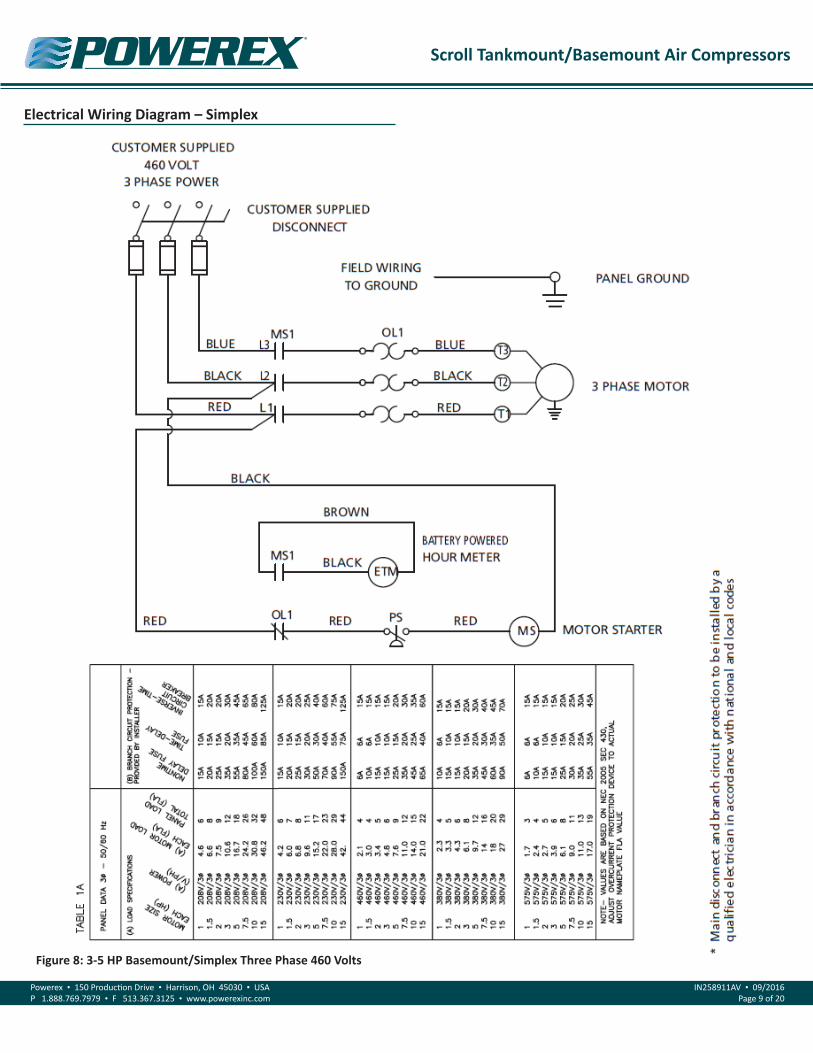
Electrical Wiring Diagram – Simplex
Figure 8: 3-5 HP Basemount/Simplex Three Phase 460 Volts

Scroll Tankmount/Basemount Air Compressors
Powerex • 150 Production Drive • Harrison, OH 45030 • USAP 1.888.769.7979 • F 513.367.3125 • www.powerexinc.com
IN258911AV • 09/2016Page 10 of 20
Electrical Wiring Diagram – Duplex
Figure 9: 3-5 HP Duplex Single Phase 208-230 Volts

Scroll Tankmount/Basemount Air Compressors
Powerex • 150 Production Drive • Harrison, OH 45030 • USAP 1.888.769.7979 • F 513.367.3125 • www.powerexinc.com
IN258911AV • 09/2016Page 11 of 20
Electrical Wiring Diagram – Duplex
Figure 10: 3-5 HP Duplex Three Phase 208-230/460/575 Volts
Scroll Tankmount/Basemount Air Compressors
Powerex • 150 Production Drive • Harrison, OH 45030 • USAP 1.888.769.7979 • F 513.367.3125 • www.powerexinc.com
IN258911AV • 09/2016Page 12 of 20
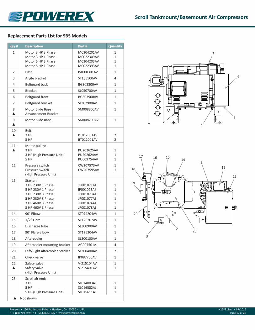
Replacement Parts List for SBS Models
Key # Description Part # Quantity
1 Motor 3 HP 3 PhaseMotor 3 HP 1 PhaseMotor 5 HP 3 PhaseMotor 5 HP 1 Phase
MC304201AVMC022309AVMC304203AVMC022393AV
1111
2 Base BA000301AV 1
3 Angle bracket ST185500AV 4
4 Beltguard back BG303800AV 1
5 Bracket SL050700AV 1
6 Beltguard front BG303900AV 1
7 Beltguard bracket SL302900AV 1
8 ▲
Motor Slide Base Advancement Bracket
SM008800AV 1
9▲
Motor Slide Base SM008700AV 1
10▲
Belt:3 HP5 HP
BT012001AVBT012001AV
22
11▲
Motor pulley:3 HP3 HP (High Pressure Unit)5 HP
PU202625AVPU202624AVPU009754AV
111
12 Pressure switchPressure switch(High Pressure Unit)
CW207573AVCW207595AV
11
13 Starter:3 HP 230V 1 Phase5 HP 230V 1 Phase3 HP 230V 3 Phase5 HP 230V 3 Phase3 HP 460V 3 Phase5 HP 460V 3 Phase
JP001071AJIP001075AJJP001073AJJP001077AJJP001074AJJP001078AJ
111111
14 90° Elbow ST074204AV 1
15 1/2” Flare ST126207AV 1
16 Discharge tube SL300900AV 1
17 90° Flare elbow ST126204AV 1
18 Aftercooler SL300100AV 1
19 Aftercooler mounting bracket AG007501AJ 4
20 Left/Right aftercooler bracket SL300400AV 2
21 Check valve IP087700AV 1
22▲
Safety valveSafety valve(High Pressure Unit)
V-215104AVV-215401AV
11
23 Scroll air end:3 HP5 HP5 HP (High Pressure Unit)
SL014003AJSL016502AJSL015611AJ
111
▲ Not shown
1
2
3
4
7
6
5
13
12
14151617
18
19
20
23

Scroll Tankmount/Basemount Air Compressors
Powerex • 150 Production Drive • Harrison, OH 45030 • USAP 1.888.769.7979 • F 513.367.3125 • www.powerexinc.com
IN258911AV • 09/2016Page 13 of 20
Replacement Parts List for STS Models
Key # Description Part # Quantity
1 Motor 3 HP 3 PhaseMotor 3 HP 1 PhaseMotor 5 HP 3 PhaseMotor 5 HP 1 Phase
MC304201AVMC022309AVMC304203AVMC022393AV
1111
2 Starter:3 HP 230V 1 Phase5 HP 230V 1 Phase3 HP 230V 3 Phase5 HP 230V 3 Phase3 HP 460V 3 Phase5 HP 460V 3 Phase
JP001071AJIP001075AJJP001073AJJP001077AJJP001074AJJP001078AJ
111111
3 Receiver tank:30 gallon60 gallon
AR024700STAR022500ST
11
4 Front beltguard BG303900AV 1
5 Motor pulley:3 HP3 HP (High Pressure Unit)5 HP
PU202625AVPU202624AVPU009754AV
111
6 Back beltguard BG303800AV 1
7 Aftercooler SL300100AV 1
8 Tube air end/aftercoolerTube air end/aftercooler(High Pressure Unit)
SL300900APSL300100AP
11
9▲
Tube aftercooler/tankTube aftercooler/tank(High Pressure Unit)
SL301400APSL300900AP
11
10 Check valve IP087700AV 1
11 Pressure gauge GA016701AV
12 Safety valveSafety valve(High Pressure Unit)
V-215104AVV-215401AV
11
13 Pressure switchPressure switch(High Pressure Unit)
CW207573AVCW207595AV
11
14 Scroll air end:3 HP5 HP5 HP (High Pressure Unit)
SL014003AJSL016502AJSL015611AJ
111
15 Belt:3 HP5 HP
BT012001AVBT012001AV
22
▲ Not shown
1
2
3
4
7
6
5
13
12
11
15
14
10
8

Scroll Tankmount/Basemount Air Compressors
Powerex • 150 Production Drive • Harrison, OH 45030 • USAP 1.888.769.7979 • F 513.367.3125 • www.powerexinc.com
IN258911AV • 09/2016Page 14 of 20
Replacement Parts List for STD Models
Key # Description Part # Quantity
1 Motor 3 HP 3 PhaseMotor 3 HP 1 PhaseMotor 5 HP 3 PhaseMotor 5 HP 1 Phase
MC304201AVMC022309AVMC304203AVMC022393AV
2222
2 Starter alternator panel:3 HP 230V 1 Phase5 HP 230V 1 Phase3 HP 230V 3 Phase5 HP 230V 3 Phase3 HP 460V 3 Phase5 HP 460V 3 Phase
PSI20036AJPSI20056AJPSI20033AJPSI20053AJPSI20034AJPSI20054AJ
111111
3 Receiver tank:80 gallon120 gallon
AR022900STAR023600ST
11
4 Front beltguard BG303900AV 2
5 Belt:3 HP5 HP
BT012001AVBT012001AV
44
6 Motor pulley:3 HP3 HP (High Pressure Unit)5 HP
PU202625AVPU202624AVPU009754AV
222
7 Back beltguard BG303800AV 2
8 Aftercooler SL300100AV 2
9 Tube air end/aftercoolerTube air end/aftercooler(High Pressure Unit)
SL300900APSL300100AP
22
10▲
Tube aftercooler/tankTube aftercooler/tank(High Pressure Unit)
SL301400APSL300900AP
22
11 Check valve IP087700AV 2
12 Pressure gauge GA016701AV 1
13 Safety valveSafety valve(High Pressure Unit)
V-215104AVV-215401AV
11
14 Pressure switch (Lag)* CW207595AV 1
15 Pressure switch (Lead) CW207595AV 1
16 Scroll air end:3 HP5 HP5 HP (High Pressure Unit)
SL014003AJSL016502AJSL015611AJ
222
* Adjust to 5 psi below Lead switch ▲ Not shown
1
2
3
4
7
5
131211
6
14
8
9
1615

Scroll Tankmount/Basemount Air Compressors
Powerex • 150 Production Drive • Harrison, OH 45030 • USAP 1.888.769.7979 • F 513.367.3125 • www.powerexinc.com
IN258911AV • 09/2016Page 15 of 20
Replacement Parts List for STS Models – Refrigerated Dryer Option
Key # Description SBS Model Part # Quantity
1 Refrigerated air dryer3 HP5 HP
ACO016010ACO016015
11
2 Regulator ST178408AJ 1
3 Electric auto tank drain SL300701AV 1
4 .01 μ Filter ST178184AV 1
5▲
.01 μ Filter element ST178185AV 1
▲ Not shown
Replacement Parts List for STD Models – Refrigerated Dryer Option
Key # Description SBS Model Part # Quantity
1 Refrigerated air dryer3 HP5 HP
ACO016025ACO016035
11
2 Regulator ST178409AV 1
3 Electric auto tank drain SL300100AV 1
4 .01 μ Filter ST178108AV 1
5▲
.01 μ Filter element ST178109AV 1
▲ Not shown
1
2
3
4
1
2
3
4

Scroll Tankmount/Basemount Air Compressors
Powerex • 150 Production Drive • Harrison, OH 45030 • USAP 1.888.769.7979 • F 513.367.3125 • www.powerexinc.com
IN258911AV • 09/2016Page 16 of 20
Troubleshooting Guide
Problem Cause Corrective Action
Compressor unit will not start 1. Main disconnect is not ON2. Blown fuse or circuit breaker at customer
provided power supply3. Blown fuse at primary side of transformer
(Duplex models)4. Pressure switch is in OPEN position
1. Switch disconnect to ON2. Inspect for any fault replace fuse or trip disconnect to ON
3. Replace fuse on primary side be sure use same type and size
4. Reduce pressure in tank
Power is at supply connection and compressor will not start
1. Blown fuse on secondary side of transformer (Duplex models)
2. Motor overload has tripped3. Wrong or low voltage4. Starter has failed5. Motor has failed
1. Replace fuse on secondary side be sure use same typeand size
2. See last entry of Troubleshooting Guide3. Check incoming power supply and unit power rating4. Replace contactor assembly5. Replace motor
Compressor is running but will not make pressure
1. Drive belts came off or too loose2. Clogged intake fi lter element3. Pressure relief valve has opened4. Excessive tip seal wear5. Electric tank drain is open continuously6. Unit running in the wrong direction7. Discharge air is leaking
1. Replace drive belts and (or) tighten2. Replace intake filter element3. Pressure switch needs replaced or starter contacts welded shut4. Replace tip seals5. Clean/replace tank drain
6. Correct power connections7. Check discharge piping
Excessive noise or vibration 1. Drive belt has separated or flat spot2. Motor has failed3. Pump is damaged4. Cooling air fan is touching fan guard
1. Replace drive belt2. Replace motor3. Fix or replace pump4. Check air fan daily
Compressor running hot 1. Room temperature is above 104° F2. Inlet air duct is obstructed3. Pump running at high pressure4. Aftercooler fi ns clogged5. Intake filter damaged6. Compressor is dirty
1. Add ventilation or air conditioning to room2. Remove obstruction or reposition unit to allow for cooling air3. Confirm tank pressure and pump outlet are not obstructed4. Clean aftercooler5. Check intake fi lter6. Clean unit
Compressor turns on/off rapidly 1. Receiver tank has high level of water2. Compressor check valve has failed3. Defective pressure switch
1. Replace electric tank drain / drain tank2. Replace check valve3. Replace pressure switch
Safety valve blows off 1. Pressure switch has failed to open2. Motor starter contacts welded shut
1. Replace pressure switch2. Replace motor starter
Motor Overload has tripped 1. Pump has failed2. Motor has failed3. Improper wiring4. Wrong overload setting5. Low voltage
1. Fix or replace pump2. Replace motor3. Check wiring4. Check overload setting5. Check incoming power supply

Scroll Tankmount/Basemount Air Compressors
Powerex • 150 Production Drive • Harrison, OH 45030 • USAP 1.888.769.7979 • F 513.367.3125 • www.powerexinc.com
IN258911AV • 09/2016Page 17 of 20
Notes

Scroll Tankmount/Basemount Air Compressors
Powerex • 150 Production Drive • Harrison, OH 45030 • USAP 1.888.769.7979 • F 513.367.3125 • www.powerexinc.com
IN258911AV • 09/2016Page 18 of 20
Notes
Scroll Tankmount/Basemount Air Compressors
Powerex • 150 Production Drive • Harrison, OH 45030 • USAP 1.888.769.7979 • F 513.367.3125 • www.powerexinc.com
IN258911AV • 09/2016Page 19 of 20
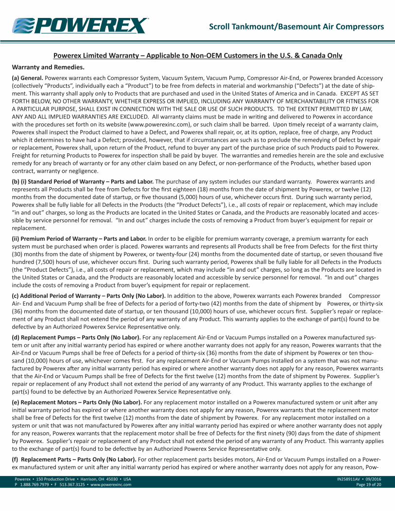
Powerex Limited Warranty – Applicable to Non-OEM Customers in the U.S. & Canada OnlyWarranty and Remedies. (a) General. Powerex warrants each Compressor System, Vacuum System, Vacuum Pump, Compressor Air-End, or Powerex branded Accessory (collectively “Products”, individually each a “Product”) to be free from defects in material and workmanship (“Defects”) at the date of ship-ment. This warranty shall apply only to Products that are purchased and used in the United States of America and in Canada. EXCEPT AS SET FORTH BELOW, NO OTHER WARRANTY, WHETHER EXPRESS OR IMPLIED, INCLUDING ANY WARRANTY OF MERCHANTABILITY OR FITNESS FOR A PARTICULAR PURPOSE, SHALL EXIST IN CONNECTION WITH THE SALE OR USE OF SUCH PRODUCTS. TO THE EXTENT PERMITTED BY LAW, ANY AND ALL IMPLIED WARRANTIES ARE EXCLUDED. All warranty claims must be made in writing and delivered to Powerex in accordance with the procedures set forth on its website (www.powerexinc.com), or such claim shall be barred. Upon timely receipt of a warranty claim, Powerex shall inspect the Product claimed to have a Defect, and Powerex shall repair, or, at its option, replace, free of charge, any Product which it determines to have had a Defect; provided, however, that if circumstances are such as to preclude the remedying of Defect by repair or replacement, Powerex shall, upon return of the Product, refund to buyer any part of the purchase price of such Products paid to Powerex. Freight for returning Products to Powerex for inspection shall be paid by buyer. The warranties and remedies herein are the sole and exclusive remedy for any breach of warranty or for any other claim based on any Defect, or non-performance of the Products, whether based upon contract, warranty or negligence.
(b) (i) Standard Period of Warranty – Parts and Labor. The purchase of any system includes our standard warranty. Powerex warrants and represents all Products shall be free from Defects for the first eighteen (18) months from the date of shipment by Powerex, or twelve (12) months from the documented date of startup, or five thousand (5,000) hours of use, whichever occurs first. During such warranty period, Powerex shall be fully liable for all Defects in the Products (the “Product Defects”), i.e., all costs of repair or replacement, which may include “in and out” charges, so long as the Products are located in the United States or Canada, and the Products are reasonably located and acces-sible by service personnel for removal. “In and out” charges include the costs of removing a Product from buyer’s equipment for repair or replacement.
(ii) Premium Period of Warranty – Parts and Labor. In order to be eligible for premium warranty coverage, a premium warranty for each system must be purchased when order is placed. Powerex warrants and represents all Products shall be free from Defects for the first thirty (30) months from the date of shipment by Powerex, or twenty-four (24) months from the documented date of startup, or seven thousand five hundred (7,500) hours of use, whichever occurs first. During such warranty period, Powerex shall be fully liable for all Defects in the Products (the “Product Defects”), i.e., all costs of repair or replacement, which may include “in and out” charges, so long as the Products are located in the United States or Canada, and the Products are reasonably located and accessible by service personnel for removal. “In and out” charges include the costs of removing a Product from buyer’s equipment for repair or replacement.
(c) Additional Period of Warranty – Parts Only (No Labor). In addition to the above, Powerex warrants each Powerex branded Compressor Air- End and Vacuum Pump shall be free of Defects for a period of forty-two (42) months from the date of shipment by Powerex, or thirty-six (36) months from the documented date of startup, or ten thousand (10,000) hours of use, whichever occurs first. Supplier’s repair or replace-ment of any Product shall not extend the period of any warranty of any Product. This warranty applies to the exchange of part(s) found to be defective by an Authorized Powerex Service Representative only.
(d) Replacement Pumps – Parts Only (No Labor). For any replacement Air-End or Vacuum Pumps installed on a Powerex manufactured sys-tem or unit after any initial warranty period has expired or where another warranty does not apply for any reason, Powerex warrants that the Air-End or Vacuum Pumps shall be free of Defects for a period of thirty-six (36) months from the date of shipment by Powerex or ten thou-sand (10,000) hours of use, whichever comes first. For any replacement Air-End or Vacuum Pumps installed on a system that was not manu-factured by Powerex after any initial warranty period has expired or where another warranty does not apply for any reason, Powerex warrants that the Air-End or Vacuum Pumps shall be free of Defects for the first twelve (12) months from the date of shipment by Powerex. Supplier’s repair or replacement of any Product shall not extend the period of any warranty of any Product. This warranty applies to the exchange of part(s) found to be defective by an Authorized Powerex Service Representative only.
(e) Replacement Motors – Parts Only (No Labor). For any replacement motor installed on a Powerex manufactured system or unit after any initial warranty period has expired or where another warranty does not apply for any reason, Powerex warrants that the replacement motor shall be free of Defects for the first twelve (12) months from the date of shipment by Powerex. For any replacement motor installed on a system or unit that was not manufactured by Powerex after any initial warranty period has expired or where another warranty does not apply for any reason, Powerex warrants that the replacement motor shall be free of Defects for the first ninety (90) days from the date of shipment by Powerex. Supplier’s repair or replacement of any Product shall not extend the period of any warranty of any Product. This warranty applies to the exchange of part(s) found to be defective by an Authorized Powerex Service Representative only.
(f) Replacement Parts – Parts Only (No Labor). For other replacement parts besides motors, Air-End or Vacuum Pumps installed on a Power-ex manufactured system or unit after any initial warranty period has expired or where another warranty does not apply for any reason, Pow-

Scroll Tankmount/Basemount Air Compressors
Powerex • 150 Production Drive • Harrison, OH 45030 • USAP 1.888.769.7979 • F 513.367.3125 • www.powerexinc.com
IN258911AV • 09/2016Page 20 of 20
erex warrants that such replacement parts will be free from Defects for the first twelve (12) months from the date of shipment by Powerex. For other replacement parts besides motors, Air-End or Vacuum Pumps installed on a system or unit that was not manufactured by Powerex after any initial warranty period has expired or where another warranty does not apply for any reason, Powerex warrants that such replace-ment parts will be free from Defects for the first twelve (12) months from the date of shipment by Powerex. For other replacement parts be-sides motors, Air-End or Vacuum Pumps installed on a system or unit that was not manufactured by Powerex after any initial warranty period has expired or where another warranty does not apply for any reason, Powerex makes no warranties. Supplier’s repair or replacement of any Product shall not extend the period of any warranty of any Product. This warranty applies to the exchange of part(s) found to be defective by an Authorized Powerex Service Representative only.
(g) Coverage. The warranty provided herein applies to Powerex manufactured units or systems only.
(h) Exceptions. Notwithstanding anything to the contrary herein, Powerex shall have no warranty obligations with respect to Products:
(i) That have not been installed in accordance with Powerex’s written specifications and instructions;
(ii) That have not been maintained in accordance with Powerex’s written instructions;
(iii) That have been materially modified without the prior written approval of Powerex; or
(iv) That experience failures resulting from operation, either intentional or otherwise, in excess of rated capacities or in an otherwise im-proper manner.
The warranty provided herein shall not apply to: (i) any defects arising from corrosion, abrasion, use of insoluble lubricants, or negligent at-tendance to or faulty operation of the Products; (ii) ordinary wear and tear of the Products; or (iii) defects arising from abnormal conditions of temperature, dirt or corrosive matter; (iv) any OEM component which is shipped by Powerex with the original manufacturer’s warranty, which shall be the sole applicable warranty for such component.
Limitation of Liability. NOTWITHSTANDING ANYTHING TO THE CONTRARY HEREIN, TO THE EXTENT ALLOWABLE UNDER APPLICABLE LAW, UNDER NO CIRCUMSTANCES SHALL POWEREX BE LIABLE FOR ANY INCIDENTAL, CONSEQUENTAL, PUNITIVE, SPECULATIVE OR INDIRECT LOSSES OR DAMAGES WHATSOEVER ARISING OUT OF OR IN ANY WAY RELATED TO ANY OF THE PRODUCTS OR GOODS SOLD OR AGREED TO BE SOLD BY POWEREX TO BUYER. TO THE EXTENT ALLOWABLE UNDER APPLICABLE LAW, POWEREX’S LIABILITY IN ALL EVENTS IS LIMITED TO, AND SHALL NOT EXCEED, THE PURCHASE PRICE PAID.
Warranty Disclaimer. Powerex has made a diligent effort to illustrate and describe the Products in its literature, including its Price Book, accu-rately; however, such illustrations and descriptions are for the sole purpose of identification, and do not express or imply a warranty that the Products are merchantable, or fit for a particular purpose, or that the Products will necessarily conform to the illustrations or descriptions.
Product Suitability. Many jurisdictions have codes and regulations governing sales, construction, installation, and/or use of Products for cer-tain purposes, which may vary from those in neighboring areas. While Powerex attempts to assure that its Products comply with such codes, it cannot guarantee compliance, and cannot be responsible for how the product is installed or used. Before purchase and use of a Product, please review the Product applications, and national and local codes and regulations, and be sure that the Product, installation, and use will comply with them.
Claims. Any non-warranty claims pertaining to the Products must be filed with Powerex within 6 months of the invoice date, or they will not be honored. Prices, discounts, and terms are subject to change without notice or as stipulated in specific Product quotations. Powerex shall not be liable for any delay or failure arising out of acts of the public enemy, fire, flood, or any disaster, labor trouble, riot or disorder, delay in the supply of materials or any other cause, whether similar or dissimilar, beyond the control of Company. All shipments are carefully inspected and counted before leaving the factory. Please inspect carefully any receipt of Products noting any discrepancy or damage on the carrier’s freight bill at the time of delivery. Discrepancies or damage which obviously occurred in transit are the carrier’s responsibility and related claims should be made promptly directly to the carrier. Returned Products will not be accepted without prior written authorization by Powerex and deductions from invoices for shortage or damage claims will not be allowed. UNLESS OTHERWISE AGREED TO IN WRITING, THE TERMS AND CONDITIONS CONTAINED IN THIS LIMITED WARRANTY WILL CONTROL IN ANY TRANSACTION WITH POWEREX. Any different or conflicting terms as may appear on any order form now or later submitted by the buyer will not control. All orders are subject to acceptance by Powerex.