Embed Size (px)
Citation preview

Scroll compressors for air-conditioningZR 18 K4*... ZR 81 KC*
Application Guidelines
C060201/0702_1002/E 2
1 Introduction
2 Nomenclature
3 How a Scroll Works
4 Qualified Refrigerants
5 Lubrication
6 Accumulators
7 Crankcase heaters
8 Pump Down
9 Reversing Valves
10 Discharge Temperature Protection
11 Standard Motor Protection
12 Mufflers
13 Low Ambient Cut-Out
14 Pressure Controls
15 Shut-Off
16 Starting
17 Deep-Vacuum Operation
18 Brief Power Interruptions
19 Electrical Installation
20 Single-Phase Models
21 Three-Phase Models
22 Cable Connectors
23 Compressor Functional Check
24 Excessive Liquid Floodback
25 Continuos Floodback
26 Repeated Floodback
27 High Potential Testing
28 Installation
29 Service
30 New Installations
31 Field Service
32 Shut-off Valves and Adaptors
33 Shell Temperature
34 System Charging Procedure
35 Unbrazing System Components
36 Suction Line Noise and Vibration
37 R 407C Characteristics
38 Application Envelopes
39 Application Diagram
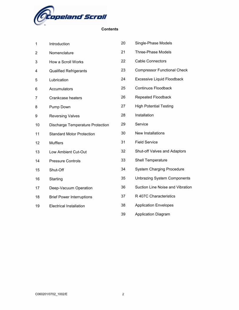
Contents
C060201/0702_1002/E 3
1 Introduction
The Compliant Scroll compressor has been under development at Copeland since 1979 and is themost efficient and durable compressor Copeland has ever developed for air conditioning, refrigerationand heat pump applications. It offers very low vibration and sound levels and is tolerant to stressescaused by liquid slugging, flooded starts, and debris commonly found in refrigeration systems. Availa-ble product range in this family is from 1,5 to 6 HP. For detailed information, please, refer to theCopeland Selection Software accessible from the Copeland website at www.ecopeland.com orprinted performance brochures. These guidelines are not meant to replace the system expertiseavailable from system manufacturers.
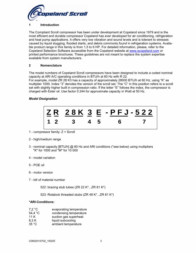
2 Nomenclature
The model numbers of Copeland Scroll compressors have been designed to include a coded nominalcapacity at ARI A/C operating conditions in BTU/h at 60 Hz with R 22.For example, model ZR 28 K3 has a capacity of approximately 28000 BTU/h at 60 Hz, using “K” asmultiplier 1000. Index “3” denotes the version of the scroll set. The “C” in this position refers to a scrollset with slightly higher built in compression ratio. If the letter “E” follows the index, the compressor ischarged with Ester oil. Use factor 0.244 for approximate capacity in Watt at 50 Hz.
Model Designation
1 - compressor family: Z = Scroll
2 - high/medium range
3 - nominal capacity [BTU/h] @ 60 Hz and ARI conditions (*see below) using multipliers "K" for 1000 and "M" for 10 000
4 - model variation
5 - POE oil
6 - motor version
7 - bill of material number
522: brazing stub tubes (ZR 22 K*...ZR 81 K*)
523: Rotalock threaded stubs (ZR 48 K*...ZR 81 K*)
*ARI-Conditions:
7,2 °C evaporating temperature54,4 °C condensing temperature11 K suction gas superheat8,3 K liquid subcooling35 °C ambient temperature
Z R 2 8 K 3 E - P F J - 5 2 21 2 3 4 5 6 7
C060201/0702_1002/E 4
1 2 3
54ANW.4.04.00
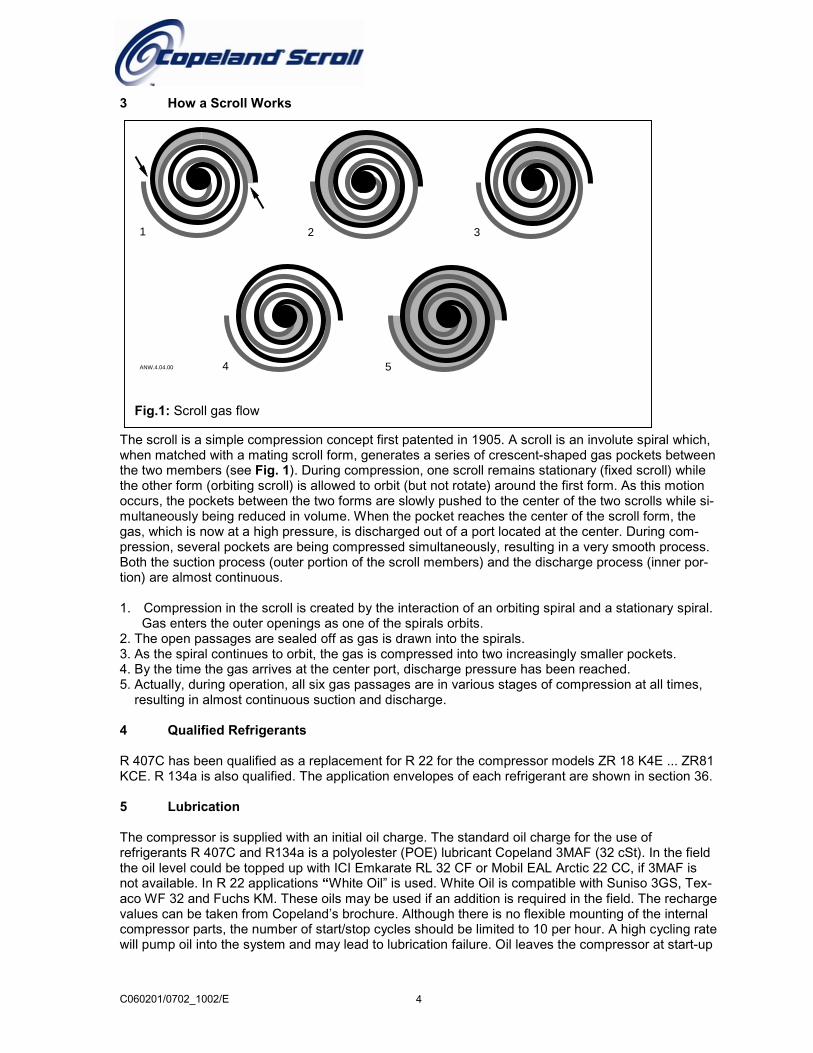
Fig.1: Scroll gas flow
3 How a Scroll Works
The scroll is a simple compression concept first patented in 1905. A scroll is an involute spiral which,when matched with a mating scroll form, generates a series of crescent-shaped gas pockets betweenthe two members (see Fig. 1). During compression, one scroll remains stationary (fixed scroll) whilethe other form (orbiting scroll) is allowed to orbit (but not rotate) around the first form. As this motionoccurs, the pockets between the two forms are slowly pushed to the center of the two scrolls while si-multaneously being reduced in volume. When the pocket reaches the center of the scroll form, thegas, which is now at a high pressure, is discharged out of a port located at the center. During com-pression, several pockets are being compressed simultaneously, resulting in a very smooth process.Both the suction process (outer portion of the scroll members) and the discharge process (inner por-tion) are almost continuous.
1. Compression in the scroll is created by the interaction of an orbiting spiral and a stationary spiral. Gas enters the outer openings as one of the spirals orbits.2. The open passages are sealed off as gas is drawn into the spirals.3. As the spiral continues to orbit, the gas is compressed into two increasingly smaller pockets.4. By the time the gas arrives at the center port, discharge pressure has been reached.5. Actually, during operation, all six gas passages are in various stages of compression at all times, resulting in almost continuous suction and discharge.
4 Qualified Refrigerants
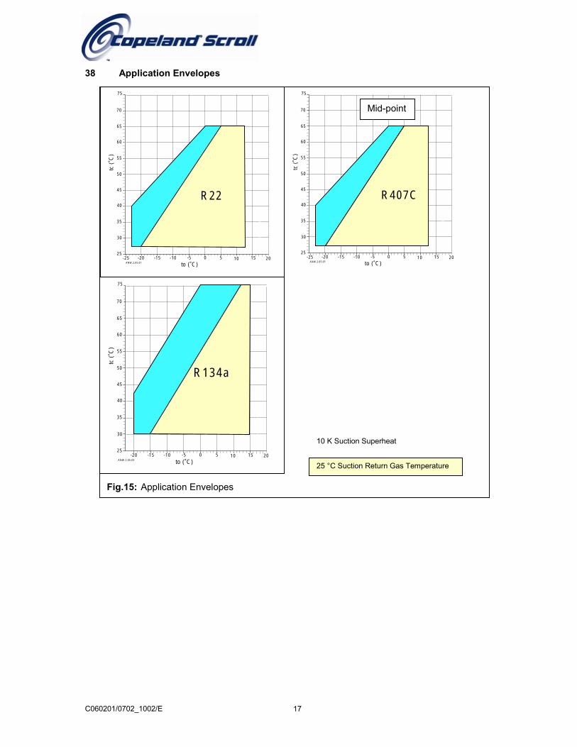
R 407C has been qualified as a replacement for R 22 for the compressor models ZR 18 K4E ... ZR81KCE. R 134a is also qualified. The application envelopes of each refrigerant are shown in section 36.
5 Lubrication
The compressor is supplied with an initial oil charge. The standard oil charge for the use ofrefrigerants R 407C and R134a is a polyolester (POE) lubricant Copeland 3MAF (32 cSt). In the fieldthe oil level could be topped up with ICI Emkarate RL 32 CF or Mobil EAL Arctic 22 CC, if 3MAF isnot available. In R 22 applications “White Oil” is used. White Oil is compatible with Suniso 3GS, Tex-aco WF 32 and Fuchs KM. These oils may be used if an addition is required in the field. The rechargevalues can be taken from Copeland’s brochure. Although there is no flexible mounting of the internalcompressor parts, the number of start/stop cycles should be limited to 10 per hour. A high cycling ratewill pump oil into the system and may lead to lubrication failure. Oil leaves the compressor at start-up
C060201/0702_1002/E 5
-25 -20 -15 -10 -5 0 5 10
te (˚C)
tb -
te (
K)
10
20
15
5
0
25
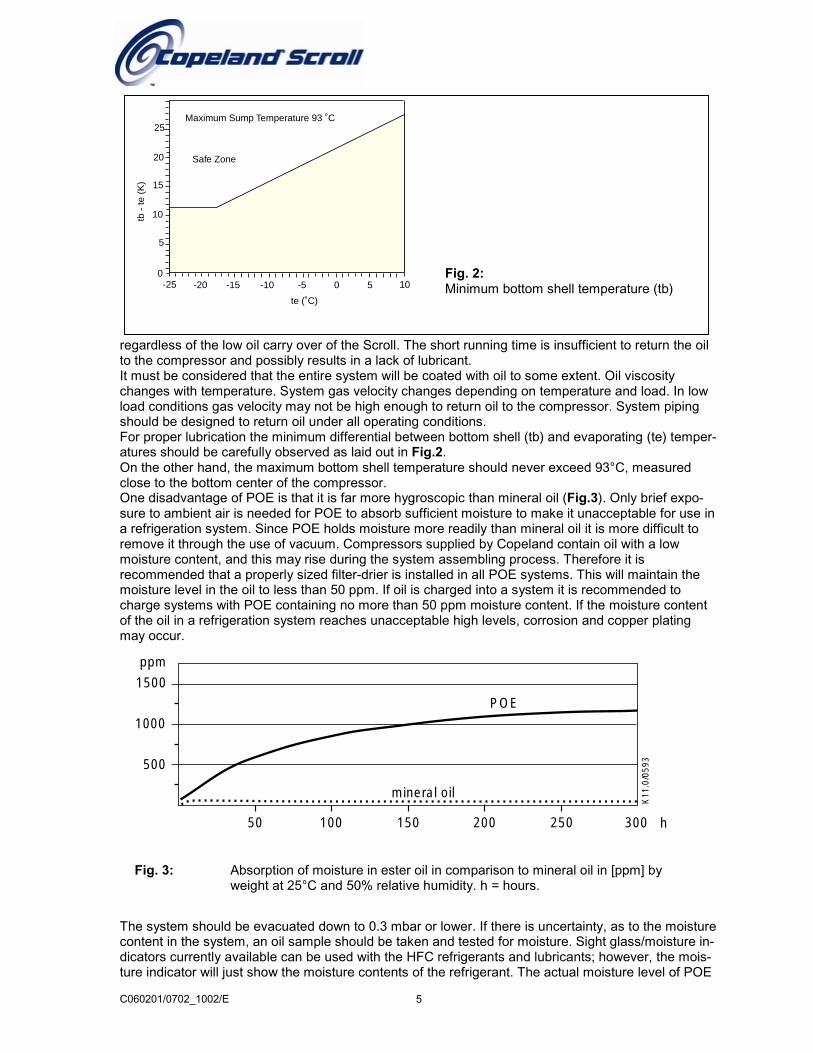
Safe Zone
Maximum Sump Temperature 93 ˚C
ppm
1500
1000
500
50 100 150 250200 300 h
mineral oil
K11
.0/0
593
POE
Fig. 3: Absorption of moisture in ester oil in comparison to mineral oil in [ppm] byweight at 25°C and 50% relative humidity. h = hours.
regardless of the low oil carry over of the Scroll. The short running time is insufficient to return the oilto the compressor and possibly results in a lack of lubricant.It must be considered that the entire system will be coated with oil to some extent. Oil viscositychanges with temperature. System gas velocity changes depending on temperature and load. In lowload conditions gas velocity may not be high enough to return oil to the compressor. System pipingshould be designed to return oil under all operating conditions.For proper lubrication the minimum differential between bottom shell (tb) and evaporating (te) temper-atures should be carefully observed as laid out in Fig.2.On the other hand, the maximum bottom shell temperature should never exceed 93°C, measuredclose to the bottom center of the compressor.One disadvantage of POE is that it is far more hygroscopic than mineral oil (Fig.3). Only brief expo-sure to ambient air is needed for POE to absorb sufficient moisture to make it unacceptable for use ina refrigeration system. Since POE holds moisture more readily than mineral oil it is more difficult toremove it through the use of vacuum. Compressors supplied by Copeland contain oil with a lowmoisture content, and this may rise during the system assembling process. Therefore it isrecommended that a properly sized filter-drier is installed in all POE systems. This will maintain themoisture level in the oil to less than 50 ppm. If oil is charged into a system it is recommended tocharge systems with POE containing no more than 50 ppm moisture content. If the moisture contentof the oil in a refrigeration system reaches unacceptable high levels, corrosion and copper platingmay occur.
The system should be evacuated down to 0.3 mbar or lower. If there is uncertainty, as to the moisturecontent in the system, an oil sample should be taken and tested for moisture. Sight glass/moisture in-dicators currently available can be used with the HFC refrigerants and lubricants; however, the mois-ture indicator will just show the moisture contents of the refrigerant. The actual moisture level of POE
Fig. 2:Minimum bottom shell temperature (tb)
SCROLL
ANW.4.05.00
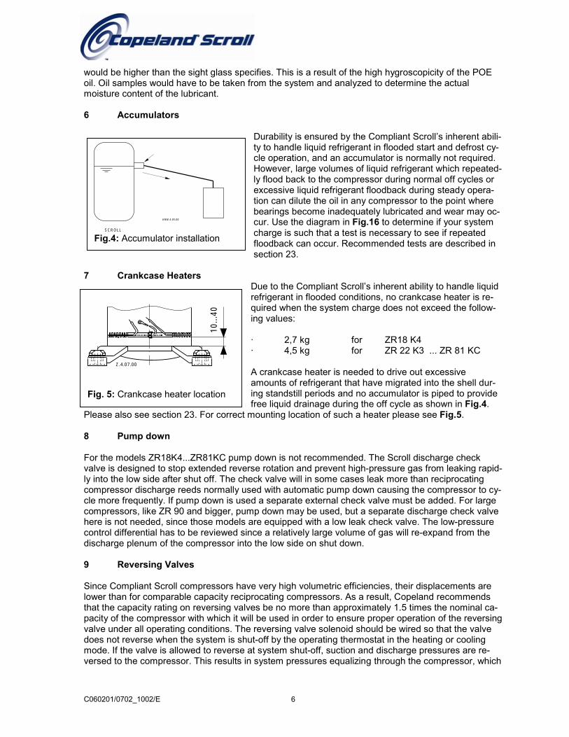
Fig.4: Accumulator installation
would be higher than the sight glass specifies. This is a result of the high hygroscopicity of the POEoil. Oil samples would have to be taken from the system and analyzed to determine the actualmoisture content of the lubricant.
6 Accumulators
Durability is ensured by the Compliant Scroll’s inherent abili-ty to handle liquid refrigerant in flooded start and defrost cy-cle operation, and an accumulator is normally not required.However, large volumes of liquid refrigerant which repeated-ly flood back to the compressor during normal off cycles orexcessive liquid refrigerant floodback during steady opera-tion can dilute the oil in any compressor to the point wherebearings become inadequately lubricated and wear may oc-cur. Use the diagram in Fig.16 to determine if your systemcharge is such that a test is necessary to see if repeatedfloodback can occur. Recommended tests are described insection 23.
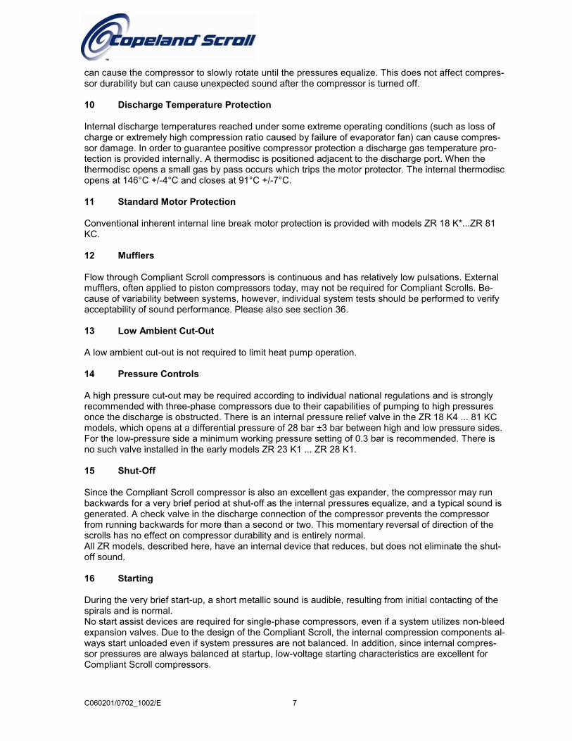
7 Crankcase HeatersDue to the Compliant Scroll’s inherent ability to handle liquidrefrigerant in flooded conditions, no crankcase heater is re-quired when the system charge does not exceed the follow-ing values:
· 2,7 kg for ZR18 K4· 4,5 kg for ZR 22 K3 ... ZR 81 KC
A crankcase heater is needed to drive out excessiveamounts of refrigerant that have migrated into the shell dur-ing standstill periods and no accumulator is piped to provide
10...
40
Z.4.07.00
Fig. 5: Crankcase heater location
C060201/0702_1002/E 6
free liquid drainage during the off cycle as shown in Fig.4.Please also see section 23. For correct mounting location of such a heater please see Fig.5.
8 Pump down
For the models ZR18K4...ZR81KC pump down is not recommended. The Scroll discharge checkvalve is designed to stop extended reverse rotation and prevent high-pressure gas from leaking rapid-ly into the low side after shut off. The check valve will in some cases leak more than reciprocatingcompressor discharge reeds normally used with automatic pump down causing the compressor to cy-cle more frequently. If pump down is used a separate external check valve must be added. For largecompressors, like ZR 90 and bigger, pump down may be used, but a separate discharge check valvehere is not needed, since those models are equipped with a low leak check valve. The low-pressurecontrol differential has to be reviewed since a relatively large volume of gas will re-expand from thedischarge plenum of the compressor into the low side on shut down.
9 Reversing Valves
Since Compliant Scroll compressors have very high volumetric efficiencies, their displacements arelower than for comparable capacity reciprocating compressors. As a result, Copeland recommendsthat the capacity rating on reversing valves be no more than approximately 1.5 times the nominal ca-pacity of the compressor with which it will be used in order to ensure proper operation of the reversingvalve under all operating conditions. The reversing valve solenoid should be wired so that the valvedoes not reverse when the system is shut-off by the operating thermostat in the heating or coolingmode. If the valve is allowed to reverse at system shut-off, suction and discharge pressures are re-versed to the compressor. This results in system pressures equalizing through the compressor, which
C060201/0702_1002/E 7
can cause the compressor to slowly rotate until the pressures equalize. This does not affect compres-sor durability but can cause unexpected sound after the compressor is turned off.
10 Discharge Temperature Protection
Internal discharge temperatures reached under some extreme operating conditions (such as loss ofcharge or extremely high compression ratio caused by failure of evaporator fan) can cause compres-sor damage. In order to guarantee positive compressor protection a discharge gas temperature pro-tection is provided internally. A thermodisc is positioned adjacent to the discharge port. When thethermodisc opens a small gas by pass occurs which trips the motor protector. The internal thermodiscopens at 146°C +/-4°C and closes at 91°C +/-7°C.
11 Standard Motor Protection
Conventional inherent internal line break motor protection is provided with models ZR 18 K*...ZR 81KC.
12 Mufflers
Flow through Compliant Scroll compressors is continuous and has relatively low pulsations. Externalmufflers, often applied to piston compressors today, may not be required for Compliant Scrolls. Be-cause of variability between systems, however, individual system tests should be performed to verifyacceptability of sound performance. Please also see section 36.
13 Low Ambient Cut-Out
A low ambient cut-out is not required to limit heat pump operation.
14 Pressure Controls
A high pressure cut-out may be required according to individual national regulations and is stronglyrecommended with three-phase compressors due to their capabilities of pumping to high pressuresonce the discharge is obstructed. There is an internal pressure relief valve in the ZR 18 K4 ... 81 KCmodels, which opens at a differential pressure of 28 bar ±3 bar between high and low pressure sides.For the low-pressure side a minimum working pressure setting of 0.3 bar is recommended. There isno such valve installed in the early models ZR 23 K1 ... ZR 28 K1.
15 Shut-Off
Since the Compliant Scroll compressor is also an excellent gas expander, the compressor may runbackwards for a very brief period at shut-off as the internal pressures equalize, and a typical sound isgenerated. A check valve in the discharge connection of the compressor prevents the compressorfrom running backwards for more than a second or two. This momentary reversal of direction of thescrolls has no effect on compressor durability and is entirely normal.All ZR models, described here, have an internal device that reduces, but does not eliminate the shut-off sound.
16 Starting
During the very brief start-up, a short metallic sound is audible, resulting from initial contacting of thespirals and is normal.No start assist devices are required for single-phase compressors, even if a system utilizes non-bleedexpansion valves. Due to the design of the Compliant Scroll, the internal compression components al-ways start unloaded even if system pressures are not balanced. In addition, since internal compres-sor pressures are always balanced at startup, low-voltage starting characteristics are excellent forCompliant Scroll compressors.
C
17 Deep-Vacuum Operation
The danger of pulling deep vacuums is avoided due to an internal low vacuum protection whichprevents the scrolls pumping (unloads) when the pressure ratio exceeds approximately 10:1. In orderto avoid nuisance trips, it is recommended to set the low-pressure control as described in section 14above.
18 Brief Power Interruptions
With single-phase Compliant Scroll compressors built before May 1995 (serial no. 95E..), brief powerinterruptions of less than 1/2 second may result in powered reverse rotation. This occurs as a resultof the high-pressure discharge gas expanding backwards through the scrolls at power interruption,causing the scroll to orbit in the reverse direction. When power is reapplied while reverse rotation isoccurring, the compressor may continue to run in the reverse direction for several minutes until thecompressor’s internal protector trips. This has no effect on durability. When the protector resets thecompressor will start and run normally.To avoid the loss of cooling resulting from powered reverse rotation Copeland strongly encouragesthe use of an electronic control which can sense brief power interruptions and will lock the compres-sor out of operation for five minutes. This control could be incorporated with the other system controls(such as defrost or thermostat), or be a stand-alone control. Functional specifications for this controlare the following:Timer opens: 1 electrical cycle (0,02 sec at 50-Hz operation) after power is removed and closes: 5minutes (± 20 %) delayed whether power is restored or not. No such device is required on three-phase models.
19 Electrical Installation
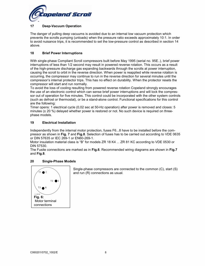
Independently from the internal motor protection, fuses F6...8 have to be installed before the com-pressor as shown in Fig. 7 and Fig.8. Selection of fuses has to be carried out according to VDE 0635or DIN 57635 or IEC 269-1 or EN60-269-1.Motor insulation material class is “B” for models ZR 18 K4 ... ZR 81 KC according to VDE 0530 orDIN 57530.The Fusite connections are marked as in Fig.6. Recommended wiring diagrams are shown in Fig.7and Fig.8.
20 Single-Phase Models
Single-phase compressors are connected to the common (C), start (S)and run (R) connections as usual.
CS
R
T1
T3
T2
E.2.09.00
Fig. 6: Motor terminalconnections
060201/0702_1002/E 8
C060201/0702_1002/E
R
M1
CS
K1
F6F1
L1 N
L1NPE
Q1
Control circuit
C2
E.1.03.00
Fig. 7: Power circuit single phase
Model PFJ T
ZR 18ZR 22ZR 28ZR 34ZR 40ZR 48ZR 61ZR 72ZR 81
A/B A/B A/B A/B A/B A/B - - -
A A A A A A C C C
A Straight receptacle B Flag recepta
Fig. 9: Cable connectors
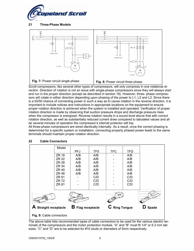
21 Three-Phase Models
Scroll compressors, like several other types of crection. Direction of rotation is not an issue withand run in the proper direction (except as descrsors will rotate in either direction depending upois a 50/50 chance of connecting power in such important to include notices and instructions in proper rotation direction is achieved when the srotation direction is made by observing that sucwhen the compressor is energized. Reverse rotrotation direction, as well as substantially reducter several minutes of operation the compressoAll three-phase compressors are wired identicadetermined for a specific system or installation,terminals should maintain proper rotation direct
22 Cable Connectors
The above table lists recommended types of caminals of the compressors and the motor protecsizes. “C” and “D” are to be selected for #10 stu
L1
M3
L2L3
K1
F6...8F1
L1 N
L1L2L3NPE
Q1
Control circuit
E.1.04.00
Fig. 8: Power circuit three phase
9
F5 TFC TFD/B/B/B/B/B/B/D/D/D
- - - - - - - - -
A/B A/B A/B A/B A/B A/B C/D C/D C/D
cle C Ring Tongue D Spade
ompressors, will only compress in one rotational di- single-phase compressors since they will always startibed in section 18). However, three- phase compres-n phasing of the power to L1, L2 and L3. Since there
a way as to cause rotation in the reverse direction, it isappropriate locations on the equipment to ensureystem is installed and operated. Verification of propertion pressure drops and discharge pressure risesation results in a sound level above that with corrected current draw compared to tabulated values and af-r’s internal protector will trip.lly internally. As a result, once the correct phasing is connecting properly phased power leads to the sameion.
ble connectors to be used for the various electric ter-tion module. “A” and “B” must fit 1/4" or 6.3 mm tabds or diameters of 5mm respectively.
C060201/0702_1002/E 10
Cable sizes are to be selected according to DIN ISO 0100, IEC 364 or national regulations.
Compressor and System Tests
23 Compressor Functional Check
Since Compliant Scroll compressors do not have internal suction valves or dynamic discharge valveswhich can be damaged it is not necessary to perform functional compressor tests where the compres-sor is turned on with the suction service valve closed to check how low the compressor will pull suc-tion pressure. Rather, the following diagnostic procedure should be used to evaluate whether theCompliant Scroll compressor is functioning properly.
1. Proper voltage to the unit should be verified.
2. The normal checks of motor winding continuity and short to ground should be made to determine ifthe internal overload motor protector of a ZR 18 K4 ... ZR 81 KC model has opened or if an internalshort to ground has developed. If the protector has opened, the compressor must be allowed to coolsufficiently to allow it to reset.. The normal checks of motor winding continuity and short to ground should be made to determine ifthe internal overload motor protector has opened or if an internal short to ground has developed. Ifthe protector has opened, the compressor must be allowed to cool sufficiently to allow it to reset.
3. Proper indoor and outdoor fan/blower operation should be verified.
4. With service gauges connected to suction and discharge pressure fittings, turn on the compressor.If suction pressure falls below normal levels the system is either low on charge or there is a flowblockage in the system.
5.a) Single-phase compressorsIf suction pressure does not drop and discharge pressure does not rise to normal levels, either the re-versing valve (if so equipped) or the compressor is faulty. Use normal diagnostic procedures to checkoperation of the reversing valve.
b) Three-phase compressorsIf suction pressure does not drop and discharge pressure does not rise to normal levels, reverse anytwo of the compressor power leads and reapply power to make sure compressor was not wired to runin reverse direction. If pressures still do not move to normal values, either the reversing valve (if soequipped) or the compressor is faulty. Reconnect the compressor leads as originally configured anduse normal diagnostic procedures to check operation of the reversing valve.
6. If the reversing valve (if so equipped) checks out satisfactorily, then the compressor current drawmust be compared to published compressor performance data at the compressor operating condi-tions (pressures and voltages) and significant deviations (more than ±15%) from published valuesmay indicate a faulty compressor.
24 Excessive Liquid Floodback
The following tests are for those system configurations and charge levels identified in Fig.16, whichneed special testing to verify exemption from the need of an accumulator.
25 Continuous Floodback
To test for excessive continuous liquid refrigerant floodback, it is necessary to operate the system in atest room at conditions where steady state floodback may occur (low ambient heating opera-tion).Thermocouples should be attached to the suction and discharge lines of the compressor (ap-proximately 150 mm from the shell) and insulated. If the system is designed to be field charged it
C060201/0702_1002/E 11
should be overcharged by 15 % in this test to simulate overcharging commonly found in field installa-tions.The system should be operated at an indoor temperature of 20°C and outdoor temperature extremes(-18°C or lower in heating mode) which produce floodback conditions. The compressor suction anddischarge pressures and temperatures should be recorded. The system should be allowed to frost upfor several hours (disabling the defrost control and spraying water on the outdoor coil may be neces-sary) to cause the saturated suction temperature to fall to -30°C or below. The compressor sumptemperature must remain above the saturated suction temperature as determined from Fig.2 ordesign changes must be made to reduce the amount of floodback. If an accumulator is used an oilreturn orifice size of 1,4 mm is recommended.
26 Repeated Floodback
To test for repeated excessive liquid floodback during normal system off-cycles perform the “Field Ap-plication Test” below. Obtain a sample compressor with a side sight tube to measure liquid level inthe compressor. Set the system up in a configuration with the indoor unit elevated approximately 1 mabove the outdoor unit with approximately 7 m of connecting tubing with no traps between the indoorand outdoor units. If the system is designed to be field charged, the system should be overcharged by15% in this test to simulate overcharging commonly found in field installations. Operate the system inthe cooling mode at the outdoor ambient, on/off cycle times and number of cycles specified in the ta-ble below. Record the height of the liquid in the compressor at the start of each on cycle, any protec-tor trips, or any compressor stalls during each test. Review all test results with Copeland ApplicationEngineering to determine if an accumulator is required for the application.
27 Field Application Test:
Outdoor ambient (°C): 29 35 40System on-time (minutes): 7 14 54System off-time (minutes): 13 8 6Number of on/off cycles: 5 5 4
To prevent flooded start damage on three phase Scroll compressors due to off cycle migration, theaccumulator may be configured on some systems to allow free drainage from the compressor to theaccumulator during the off cycle.Please see Fig.2. When this configuration is not possible, a crankcase heater is required.
27 High Potential Testing
Copeland subjects all motor compressors to a high voltage test after final assembly. This is carriedout according to VDE 0530 part 1.Since high voltage tests lead to premature aging of the winding insulation we do not recommend ad-ditional tests of that nature. They may also be carried out with new machines only.If it has to be done for any reason disconnect all electronic devices (e.g. motor protection module, fanspeed control, etc.) prior to testing. The test voltage of 1000 V plus twice the nominal voltage is ap-plied for 1 - 4 seconds between motor winding (each one of the phases) and the compressor shell:The maximum leak current limit is approximately 10 mA. Repeated tests have to be performed at low-er voltages.
Caution: Do not carry out high voltage or insulation tests if the compressor housing is under vacuum.Compliant Scroll compressors are configured with the motor down and the pumping components atthe top of the shell. As a result, the motor can be immersed in refrigerant to a greater extent than her-metic reciprocating compressors when liquid refrigerant is present in the shell. In this respect, thescroll is more like semi-hermetics (which have horizontal motors partially submerged in oil and refrig-erant). When Compliant Scroll compressors are high potential tested with liquid refrigerant in the shellthey can show higher levels of leakage current than compressors with the motor on top because ofthe higher electrical conductivity of liquid refrigerant than refrigerant vapour and oil. However, thisphenomenon can occur with any compressor when the motor is immersed in refrigerant. The levels of
current leakage do not present any safety issue. To lower the current leakage reading the systemshould be operated for a brief period of time to redistribute the refrigerant to a more normal configura-tion and the system high potential tested again.
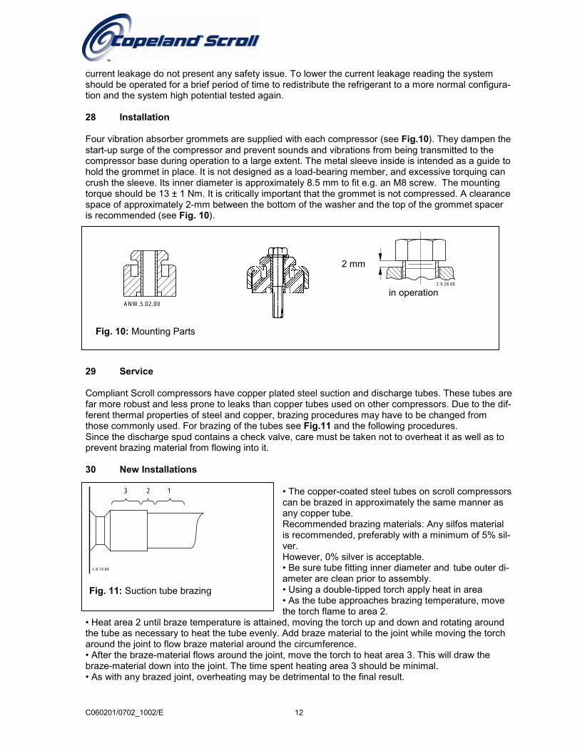
28 Installation
Four vibration absorber grommets are supplied with each compressor (see Fig.10). They dampen thestart-up surge of the compressor and prevent sounds and vibrations from being transmitted to thecompressor base during operation to a large extent. The metal sleeve inside is intended as a guide tohold the grommet in place. It is not designed as a load-bearing member, and excessive torquing cancrush the sleeve. Its inner diameter is approximately 8.5 mm to fit e.g. an M8 screw. The mountingtorque should be 13 ± 1 Nm. It is critically important that the grommet is not compressed. A clearancespace of approximately 2-mm between the bottom of the washer and the top of the grommet spaceris recommended (see Fig. 10).
Z.9.28.00
in operation
2 mm
ANW.5.02.00
Fig. 10: Mounting Parts
C060201/0702_1002/E
3 2 1
Z.8.14.00
Fig. 11: Suction tube bra
29 Service
Compliant Scroll compresfar more robust and less pferent thermal properties othose commonly used. FoSince the discharge spud prevent brazing material fr
30 New Installations
• Heat area 2 until braze tethe tube as necessary to haround the joint to flow bra• After the braze-material fbraze-material down into t• As with any brazed joint,
zing
sors haverone to lef steel anr brazing contains om flowin
mperatueat the tuze materlows arouhe joint. T overheat
12
copper plated steel suction and discharge tubes. These tubes areaks than copper tubes used on other compressors. Due to the dif-d copper, brazing procedures may have to be changed fromof the tubes see Fig.11 and the following procedures.a check valve, care must be taken not to overheat it as well as tog into it.
• The copper-coated steel tubes on scroll compressorscan be brazed in approximately the same manner asany copper tube.Recommended brazing materials: Any silfos materialis recommended, preferably with a minimum of 5% sil-ver.However, 0% silver is acceptable.• Be sure tube fitting inner diameter and tube outer di-ameter are clean prior to assembly.• Using a double-tipped torch apply heat in area• As the tube approaches brazing temperature, movethe torch flame to area 2.
re is attained, moving the torch up and down and rotating aroundbe evenly. Add braze material to the joint while moving the torchial around the circumference.nd the joint, move the torch to heat area 3. This will draw thehe time spent heating area 3 should be minimal.ing may be detrimental to the final result.
C060201/0702_1002/E 13
a
c
b
(1) (2)
Z.8.07.00
c
ba
Z.8.08.00 Z.8.10.00
c
b
a
d
Z.8.09.00
. .a b
c
Z.8.11.00
Fig. 12: Shut-off valves and adaptors
31 Field Service
To disconnect:
• Heat joint areas 2 and 3 slowly and uniformly until the braze material softens and the tube can bepulled out of the fitting.
To reconnect:• Recommended brazing-materials: Silfos with minimum 5% silver or silver braze used on other com-pressors. Due to the different thermal properties of steel and copper, brazing procedures may have tobe changed from those commonly used. For brazing of the tubes see Fig.11 and the following proce-dures.Since the discharge stub contains a check valve, care must be taken not to overheat it as well as toprevent brazing material to flow into it.
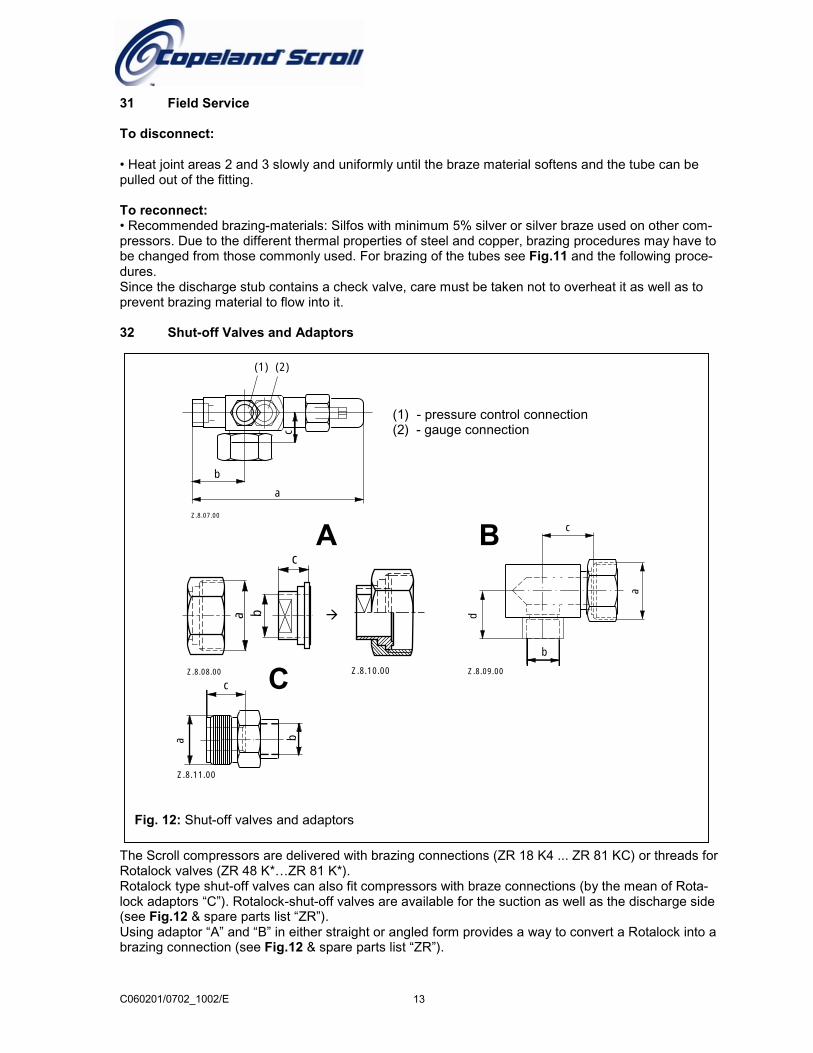
32 Shut-off Valves and Adaptors
The Scroll compressors are delivered with brazing connections (ZR 18 K4 ... ZR 81 KC) or threads forRotalock valves (ZR 48 K*…ZR 81 K*).Rotalock type shut-off valves can also fit compressors with braze connections (by the mean of Rota-lock adaptors “C”). Rotalock-shut-off valves are available for the suction as well as the discharge side(see Fig.12 & spare parts list “ZR”).Using adaptor “A” and “B” in either straight or angled form provides a way to convert a Rotalock into abrazing connection (see Fig.12 & spare parts list “ZR”).
A B
C
�
(1) - pressure control connection(2) - gauge connection
33 Shell Temperature
Under rare circumstances caused by failure of system components such as the condenser or evapo-rator fan, or loss of charge, and depending on the type of expansion control, the top shell and dis-charge line can briefly but repeatedly reach temperatures above 177°C as the compressor cycles onits internal protection devices. Care must be taken to ensure that wiring or other materials whichcould be damaged by these temperatures do not come into contact with the shell.
34 System Charging Procedure
Rapid charging on only the suction side of a single-phase Scroll equipped system or condensing unitcan occasionally result in a temporary no-start condition for the compressor. The reason for this isthat if the flanks of the spirals happen to be in a sealed position, rapid pressurization of the low sidewithout opposing high side pressure can cause the spirals to seal axially. As a result, until thepressures eventually equalize, the spirals can be held tightly together, preventing rotation. The bestway to avoid this situation is to charge on both the high and the low side simultaneously at a ratewhich does not result in axial loading of the spirals. The maximum charging rate can be determinedthrough simple tests.
35 Unbrazing System Components
If the refrigerant charge is removed from a scroll equipped unit by bleeding the high side only, it issometimes possible for the scrolls to seal, preventing pressure equalization through the compressor.This may leave the low side shell and suction line tubing pressurized. If a brazing torch is the appliedto the low side while the low side shell and suction line contains pressure, the pressurized refrigerantand oil mixtures could ignite when it escapes and contacts the brazing flame. To prevent thisoccurrence, it is important to check both the high and the low side with gauges before unbrazing, or inthe case of repairing a unit on an assembly line, bleed refrigerant from both the low and the high side.Instructions should be provided in appropriate product literature and assembly (line repair) areas.
36 Suction Line Noise and Vibration
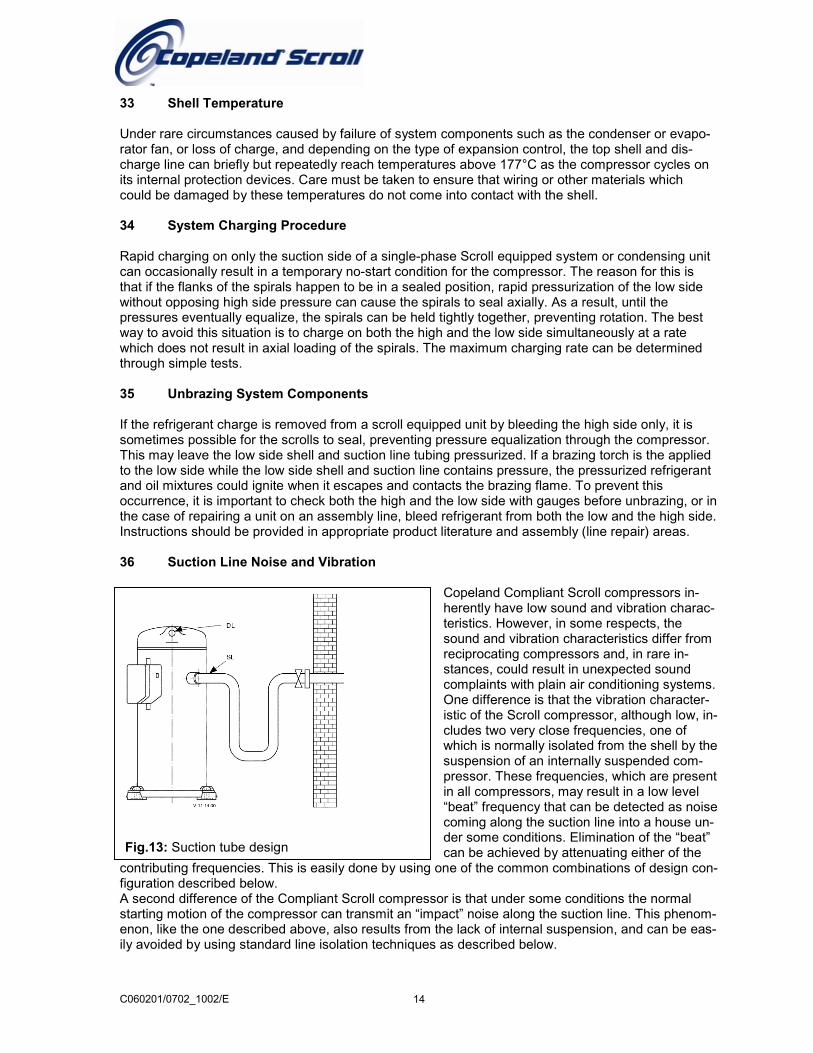
Copeland Compliant Scroll compressors in-herently have low sound and vibration charac-teristics. However, in some respects, thesound and vibration characteristics differ fromreciprocating compressors and, in rare in-stances, could result in unexpected soundcomplaints with plain air conditioning systems.One difference is that the vibration character-istic of the Scroll compressor, although low, in-cludes two very close frequencies, one ofwhich is normally isolated from the shell by thesuspension of an internally suspended com-pressor. These frequencies, which are presentin all compressors, may result in a low level“beat” frequency that can be detected as noisecoming along the suction line into a house un-der some conditions. Elimination of the “beat”can be achieved by attenuating either of the
Fig.13: Suction tube designC060201/0702_1002/E 14
contributing frequencies. This is easily done by using one of the common combinations of design con-figuration described below.A second difference of the Compliant Scroll compressor is that under some conditions the normalstarting motion of the compressor can transmit an “impact” noise along the suction line. This phenom-enon, like the one described above, also results from the lack of internal suspension, and can be eas-ily avoided by using standard line isolation techniques as described below.
C
Recommended configuration (Fig.13 ):
• Tubing configuration: small shock loop• Service valve: “angled valve” fastened to unit/wall• Suction muffler: not required
Alternative configuration:
• Tubing configuration: small shock loop• Service valve: “straight-through” valve fastened to unit/wall• Suction muffler: may be required
The sound phenomena described above are not usually associated with reversible air conditioning/heat pump systems because of the isolation and attenuation provided by the reversing valve and tubing bends.
37 R 407C Characteristics
CpvenpcaPindAotiospo
060201/0702_1002/E 15
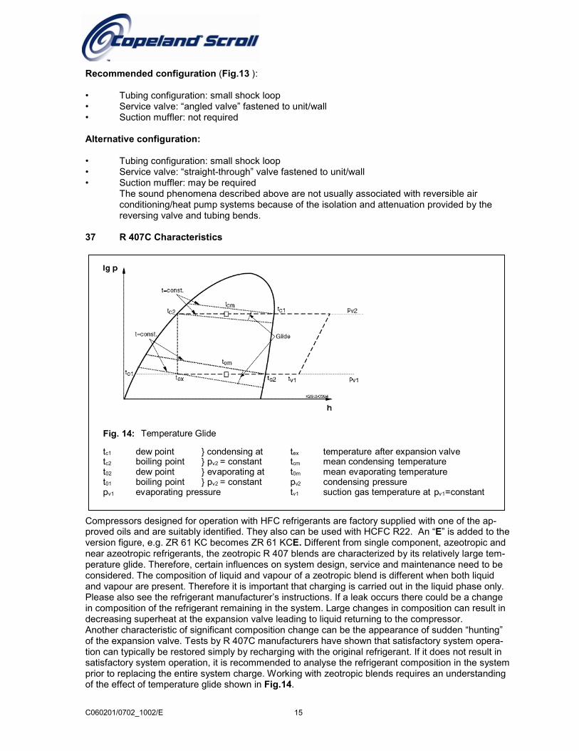
Fig. 14: Temperature Glide
tc1 dew point } condensing attc2 boiling point } pv2 = constantt02 dew point } evaporating att01 boiling point } pv2 = constantpv1 evaporating pressure
tex temperature after expansion valvetcm mean condensing temperaturet0m mean evaporating temperaturepv2 condensing pressuretv1 suction gas temperature at pv1=constant
ompressors designed for operation with HFC refrigerants are factory supplied with one of the ap-roved oils and are suitably identified. They also can be used with HCFC R22. An “E” is added to thersion figure, e.g. ZR 61 KC becomes ZR 61 KCE. Different from single component, azeotropic and
ear azeotropic refrigerants, the zeotropic R 407 blends are characterized by its relatively large tem-erature glide. Therefore, certain influences on system design, service and maintenance need to beonsidered. The composition of liquid and vapour of a zeotropic blend is different when both liquidnd vapour are present. Therefore it is important that charging is carried out in the liquid phase only.lease also see the refrigerant manufacturer’s instructions. If a leak occurs there could be a change composition of the refrigerant remaining in the system. Large changes in composition can result inecreasing superheat at the expansion valve leading to liquid returning to the compressor.nother characteristic of significant composition change can be the appearance of sudden “hunting”f the expansion valve. Tests by R 407C manufacturers have shown that satisfactory system opera-n can typically be restored simply by recharging with the original refrigerant. If it does not result in
atisfactory system operation, it is recommended to analyse the refrigerant composition in the systemrior to replacing the entire system charge. Working with zeotropic blends requires an understandingf the effect of temperature glide shown in Fig.14.
C060201/0702_1002/E 16
Evaporation at constant pressure takes place with the temperature of the refrigerant increasing fromtex to to2 and condensation takes place with a falling temperature from tc1 to tc2. Thus the terms“evaporating temperature” and “condensing temperature” must be redefined. High glide causes con-siderable temperature differences within the heat exchangers. Similarly, clear definitions for “super-heating” and “subcooling” are needed. Such new definitions are also necessary in order to ensure ac-curate comparisons of performance against other azeotropic or near azeotropic refrigerants. Evapo-rating temperature is defined as the mean temperature (tom) between the dew-point temperature(to2) resulting from constant suction pressure (pv1) and the temperature at which the refrigerant en-ters the evaporator (tex). Condensing temperature is defined as the mean temperature (tcm) betweenthe dew-point temperature (tc1) resulting from constant discharge pressure (pv2) and the boiling-pointtemperature (tc2) of the refrigerant.The superheating of the suction gas is then calculated as the difference in temperature at the com-pressor inlet (tv1) and the dew-point temperature (to2) of the refrigerant at suction pressure (pv1). It isessential that these definitions be followed when adjusting the superheat setting of expansion valves.Liquid subcooling is calculated as the difference between actual liquid temperature and the bubblepoint temperature (tc2) of the refrigerant at discharge pressure (pv2).The definitions presented here are based on those specified by the Air- Conditioning and Refrigera-tion Institute (ARI) as part of their Alternative Refrigerants Evaluation Program (AREP). Thesedefinitions are used to provide performance comparison with R 22. System designers normally usedata based on the dew point temperatures as specified in EN 12900. With the Copeland SelectionSoftware version 4 and above performance data sheets for both mid point and dew point definitionsare available.It is essential that the glide of R 407 refrigerant blends be given careful consideration when adjustingpressure controls. Furthermore, it is crucial to consider the effect of pressure losses on glide whensizing heat exchangers. Pressure losses effectively increase glide significantly in the system. Failureto consider this in heat energy balance calculations will likely result in undersizing heat exchangersand other system components. These effects are especially apparent when operating a system nearthe limits of its application range.
C060
20
38 Application Envelopes
Fig.
Fig.13: Application Envelopes
Fig.15: Application Envelopes
-20 -15 -10 -5 0 5 10 15
to (˚C)ANW.2.05.03
65
60
55
50
45
40
35
30
25
tc (
˚C)
70
75
R134a
20
-20 -15 -10 -5 0 5 10 15
to (˚C)ANW.2.05.05
65
60
55
50
45
40
35
30
25
tc (
˚C)
70
75
R407C
-25-20 -15 -10 -5 0 5 10 15
to (˚C)ANW.2.05.01
65
60
55
50
45
40
35
30
25
tc (
˚C)
70
75
R22
20-25
10 K Suction Superheat
25 °C Suction Return Gas Temperature
Mid-point
201/0702_1002/E 17
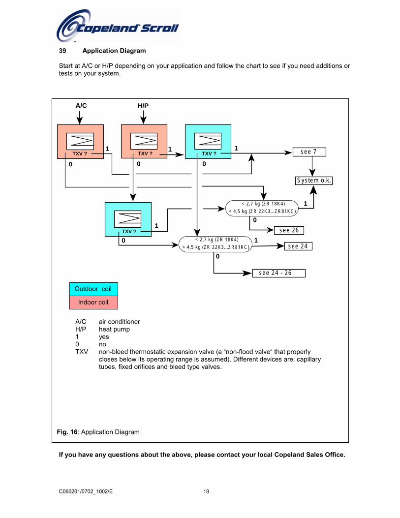
39 Application Diagram
Start at A/C or H/P depending on your application and follow the chart to see if you need additions ortests on your system.
TXV ? TXV ? TXV ?
TXV ?
see 7
System o.k.
< 2,7 kg (ZR 18K4)
< 2,7 kg (ZR 18K4)
see 26
see 24 - 26
see 240
0 0 0
0
1 1
1
1
1
1
0
< 4,5 kg (ZR 22K3...ZR81KC)
< 4,5 kg (ZR 22K3...ZR81KC)
A/C H/P
Fig. 16: Application Diagram
Outdoor coil
Indoor coil
A/C air conditionerH/P heat pump1 yes0 noTXV non-bleed thermostatic expansion valve (a “non-flood valve“ that properly
closes below its operating range is assumed). Different devices are: capillarytubes, fixed orifices and bleed type valves.
C060201/0702_1002/E 18
If you have any questions about the above, please contact your local Copeland Sales Office.