Embed Size (px)
Citation preview
SCR on Filter Based Aftertreatment for High Efficiency Engine Systems
A UK based Energy Technologies Institute Funded Project
*R.G. Silver, **T.E. Paulson – Caterpillar Inc
*J.C. Martin – Johnson Matthey Catalyst
(*Co-authors) (**Presenter)
Outline
Introduction
• Global, collaborative project
Results for NRTC and WHTC legislative cycles
• System design impact
• Summary of GHG Emissions
Results for in-use vocational cycles
• Work Based Windows Analysis
Conclusion

• Public-private partnership between global energy and
engineering companies and the UK Government.
• Develop, demonstrate and de-risk new technologies for
affordable and secure energy, and lower GHG emissions
• Global consortium between Caterpillar, Johnson Matthey,
and Loughborough University to develop aftertreatment for
next gen HDD engines
Introduction
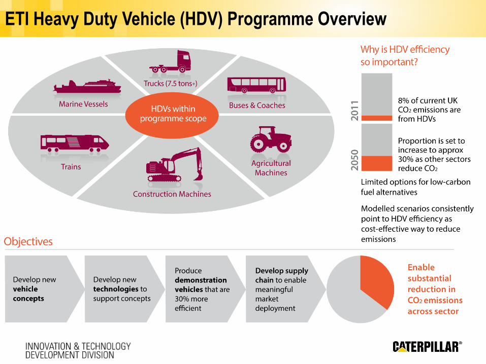
ETI Heavy Duty Vehicle (HDV) Programme Overview
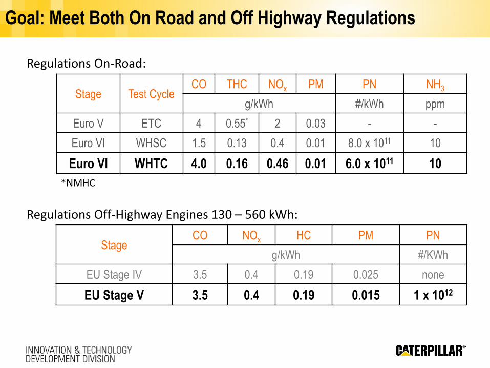
Goal: Meet Both On Road and Off Highway Regulations
Stage Test CycleCO THC NOx PM PN NH3
g/kWh #/kWh ppm
Euro V ETC 4 0.55* 2 0.03 - -
Euro VI WHSC 1.5 0.13 0.4 0.01 8.0 x 10¹¹ 10
Euro VI WHTC 4.0 0.16 0.46 0.01 6.0 x 10¹¹ 10
Regulations On-Road:
*NMHC
Regulations Off-Highway Engines 130 – 560 kWh:
StageCO NOx HC PM PN
g/kWh #/KWh
EU Stage IV 3.5 0.4 0.19 0.025 none
EU Stage V 3.5 0.4 0.19 0.015 1 x 10¹²
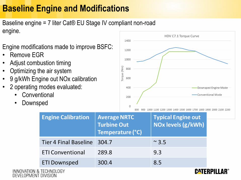
Baseline Engine and Modifications
Baseline engine = 7 liter Cat® EU Stage IV compliant non-road
engine.
Engine modifications made to improve BSFC:
• Remove EGR
• Adjust combustion timing
• Optimizing the air system
• 9 g/kWh Engine out NOx calibration
• 2 operating modes evaluated:
• Conventional
• Downsped
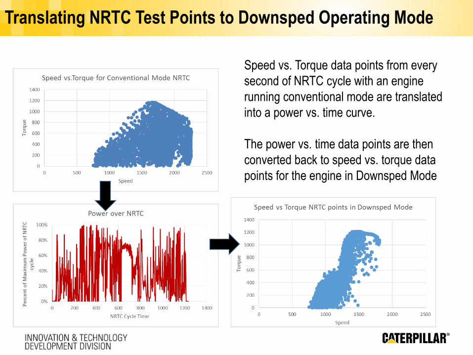
Translating NRTC Test Points to Downsped Operating Mode
Speed vs. Torque data points from every
second of NRTC cycle with an engine
running conventional mode are translated
into a power vs. time curve.
The power vs. time data points are then
converted back to speed vs. torque data
points for the engine in Downsped Mode
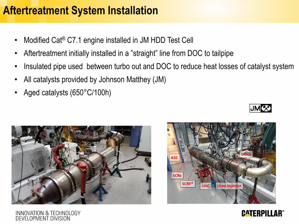
Aftertreatment System Installation
• Modified Cat® C7.1 engine installed in JM HDD Test Cell
• Aftertreatment initially installed in a ”straight” line from DOC to tailpipe
• Insulated pipe used between turbo out and DOC to reduce heat losses of catalyst system
• All catalysts provided by Johnson Matthey (JM)
• Aged catalysts (650°C/100h)
System
Cu-SCRF®
DEF
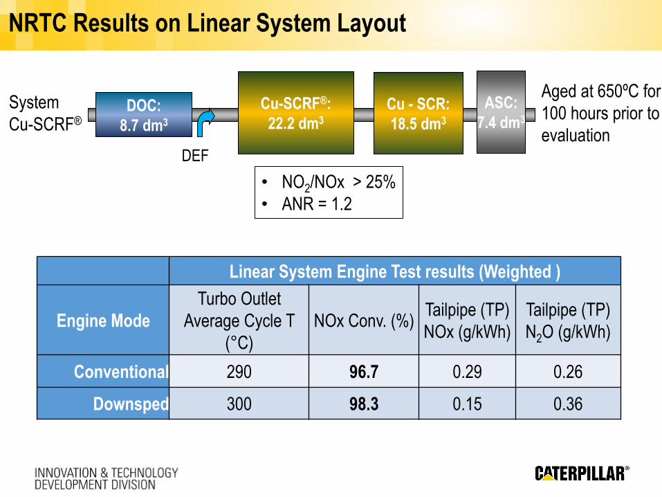
NRTC Results on Linear System Layout
Aged at 650ºC for
100 hours prior to
evaluation
• NO2/NOx > 25%
• ANR = 1.2
Linear System Engine Test results (Weighted )
Engine Mode
Turbo Outlet
Average Cycle T
(°C)
NOx Conv. (%)Tailpipe (TP)
NOx (g/kWh)
Tailpipe (TP)
N2O (g/kWh)
Conventional 290 96.7 0.29 0.26
Downsped 300 98.3 0.15 0.36
Cu-SCRF®:
22.2 dm3DOC:
8.7 dm3
Cu - SCR:
18.5 dm3
ASC:
7.4 dm3
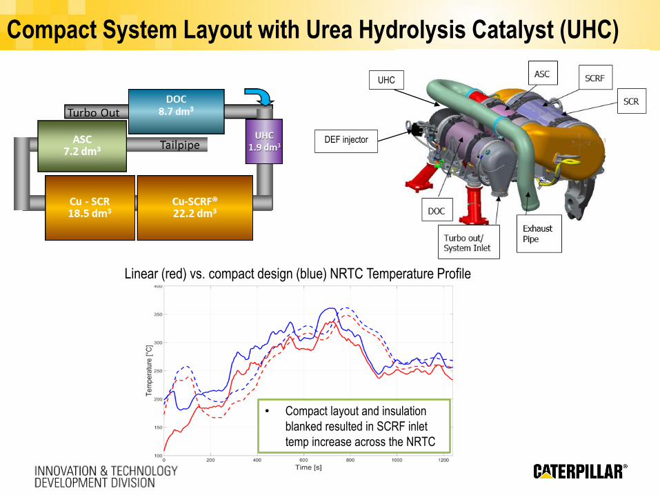
Compact System Layout with Urea Hydrolysis Catalyst (UHC)
UHC
DEF injector
Linear (red) vs. compact design (blue) NRTC Temperature Profile
• Compact layout and insulation
blanked resulted in SCRF inlet
temp increase across the NRTC
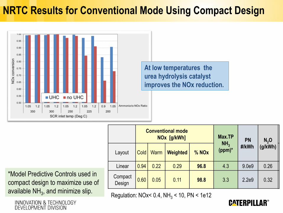
NRTC Results for Conventional Mode Using Compact Design
Conventional mode
NOx [g/kWh] Max.TP
NH3
(ppm)*
PN
#/kWh
N2O
(g/kWh)Layout Cold Warm Weighted % NOx
Linear 0.94 0.22 0.29 96.8 4.3 9.0e9 0.26
Compact
Design0.60 0.05 0.11 98.8 3.3 2.2e9 0.32
At low temperatures the
urea hydrolysis catalyst
improves the NOx reduction.
Regulation: NOx< 0.4, NH3 < 10, PN < 1e12
*Model Predictive Controls used in
compact design to maximize use of
available NH3, and minimize slip.
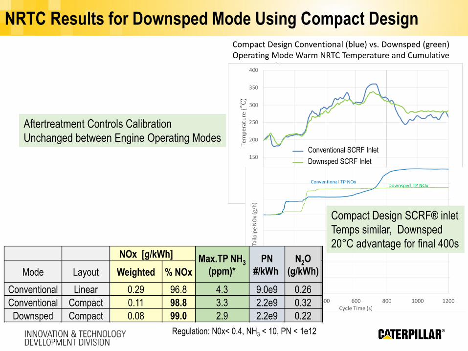
NRTC Results for Downsped Mode Using Compact Design
Regulation: N0x< 0.4, NH3 < 10, PN < 1e12
Aftertreatment Controls Calibration
Unchanged between Engine Operating Modes
Compact Design Conventional (blue) vs. Downsped (green) Operating Mode Warm NRTC Temperature and Cumulative TP NOx Profile
Downsped SCRF Inlet
Conventional SCRF Inlet
NOx [g/kWh] Max.TP NH3
(ppm)*
PN
#/kWh
N2O
(g/kWh)Mode Layout Weighted % NOx
Conventional Linear 0.29 96.8 4.3 9.0e9 0.26
Conventional Compact 0.11 98.8 3.3 2.2e9 0.32
Downsped Compact 0.08 99.0 2.9 2.2e9 0.22
Compact Design SCRF® inlet
Temps similar, Downsped
20°C advantage for final 400s
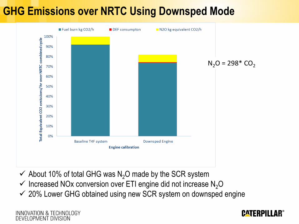
GHG Emissions over NRTC Using Downsped Mode
13
About 10% of total GHG was N2O made by the SCR system
Increased NOx conversion over ETI engine did not increase N2O
20% Lower GHG obtained using new SCR system on downsped engine
N2O = 298* CO2
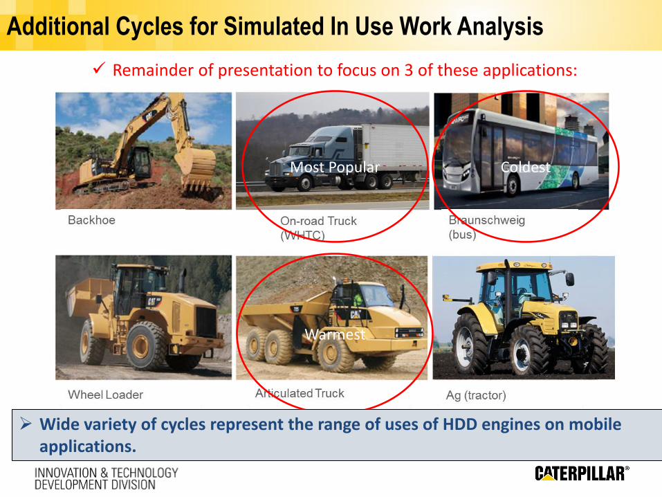
Additional Cycles for Simulated In Use Work Analysis
Most Popular
Warmest
Remainder of presentation to focus on 3 of these applications:
Coldest
Wide variety of cycles represent the range of uses of HDD engines on mobile applications.
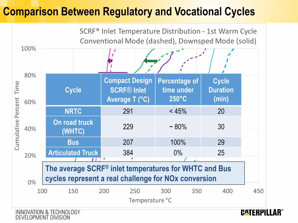
Comparison Between Regulatory and Vocational Cycles
Articulated Truck
On Road Truck
BUS
NRTC cycle
The average SCRF® inlet temperatures for WHTC and Bus
cycles represent a real challenge for NOx conversion
Cycle
Compact Design
SCRF® Inlet
Average T (°C)
Percentage of
time under
250°C
Cycle
Duration
(min)
NRTC 291 < 45% 20
On road truck
(WHTC)229 ~ 80% 30
Bus 207 100% 29
Articulated Truck 384 0% 25
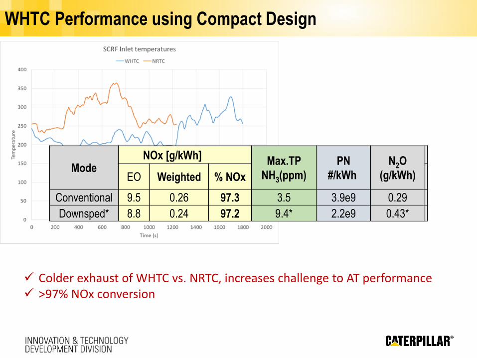
WHTC Performance using Compact Design
Colder exhaust of WHTC vs. NRTC, increases challenge to AT performance >97% NOx conversion
ModeNOx [g/kWh] Max.TP
NH3(ppm)
PN
#/kWh
N2O
(g/kWh)EO Weighted % NOx
Conventional 9.5 0.26 97.3 3.5 3.9e9 0.29
Downsped* 8.8 0.24 97.2 9.4* 2.2e9 0.43*
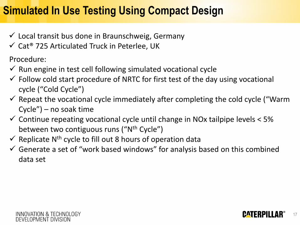
Simulated In Use Testing Using Compact Design
17
Procedure: Run engine in test cell following simulated vocational cycle Follow cold start procedure of NRTC for first test of the day using vocational
cycle (“Cold Cycle”) Repeat the vocational cycle immediately after completing the cold cycle (“Warm
Cycle”) – no soak time Continue repeating vocational cycle until change in NOx tailpipe levels < 5%
between two contiguous runs (“Nth Cycle”) Replicate Nth cycle to fill out 8 hours of operation data Generate a set of “work based windows” for analysis based on this combined
data set
Local transit bus done in Braunschweig, Germany Cat® 725 Articulated Truck in Peterlee, UK
Bus Cycle Cumulative TP NOx Improves With Repetition; Conventional
(Dashed Lines)
Performance Evaluation Using Simulated In Use Testing
18
Nth Cycle
1st
Warm
Cold
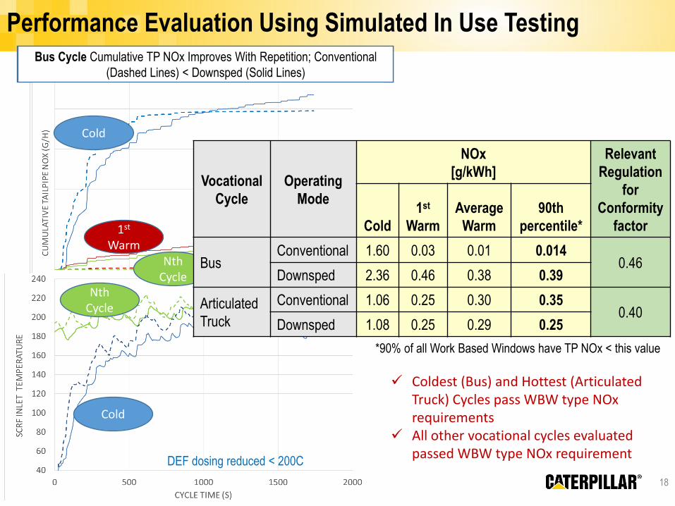
Bus Cycle Cumulative TP NOx Improves With Repetition; Conventional
(Dashed Lines) < Downsped (Solid Lines)
Cold
Nth Cycle
DEF dosing reduced < 200C
*90% of all Work Based Windows have TP NOx < this value
Coldest (Bus) and Hottest (Articulated Truck) Cycles pass WBW type NOxrequirements
All other vocational cycles evaluated passed WBW type NOx requirement
Vocational
Cycle
Operating
Mode
NOx
[g/kWh]
Relevant
Regulation
for
Conformity
factorCold
1st
Warm
Average
Warm
90th
percentile*
BusConventional 1.60 0.03 0.01 0.014
0.46Downsped 2.36 0.46 0.38 0.39
Articulated
Truck
Conventional 1.06 0.25 0.30 0.350.40
Downsped 1.08 0.25 0.29 0.25
Summary and Conclusions
An SCR on Filter (SCRF®) based aftertreatment system was evaluated using a high
efficiency engine operating in either conventional or downsped mode.
EU Stage V and Euro VI regulations for NOx, PN, and NH3 slip were met over each
operating mode.
In-use compliance was demonstrated using WBW type analysis over relatively hot
(Articulated Truck) and cold (Bus) vocational cycles over each operating mode.
The downsped mode reduces GHG emissions due mainly to lower BSFC while
simultaneously holding N2O formation constant over the AT system despite
increased NOx conversion.
>97% NOx conversions for most applications were similar over both operating
modes, despite downsped mode exhaust being colder. Conversions over the
downsped bus cycle were lower than conventional mode due to increased %cycle
time spent below 200°C (50% vs. 70%), where urea dosing was limited.
A versatile Cu SCRF® based aftertreatment system has been developed to provide
high NOx conversion and PN reduction to meet future emission regulations on
advanced engine technologies.

Thank you for your attention – Any questions?
Authors
Dr. Ronald Silver
Caterpillar Inc
Dr. Juan Carlos Martin P.
Johnson Matthey
Ben Reid – Loughborough University
Andy Cawdery – Caterpillar UK (Perkins)
Michael Nash – Johnson Matthey
Jonas Edvardsson – Johnson Matthey
Funding: Energy Technologies Institute
Chris Thorne, David Butler - ETI
Acknowledgements
Presented by
Dr. Thomas Paulson
Caterpillar Inc