Embed Size (px)
Citation preview

ScopeFebruary 2013
the Palomar Amateur Radio Club newsletter
SCOPE page 2
Club Meeting
Save the Date Board Meeting Field Day Work Parties
The 7:30pm program will be about High Speed MultiMedia (HSMM) Mesh by Andre K6AH.
Palomar Amateur Radio Club board meeting at 7:30pm at K2RP QTH.
At TowWizard. Contact Greg KI6RXX or Charlie NN3V to volunteer.
6 February 2013 13 February 2013 9, 13 February
HAM RADIO OUTLET
Jerry N5MCJ Joe N6SIX
Jose XE2SJB
H R O
Open: 10a.m. – 5:30p.m. Monday thru Saturday 858 560-4900 or toll free 1-800-854-6046
KENWOOD rf CONCEPTS DIAMOND US TOWERS KANTRONICS YAESU, MFJ, ICOM BENCHER, Inc. HUSTLER COMET AMERITRON
Directions: On 163, take Clairemont Mesa Blvd. off ramp to East. Stay in right-hand lane. Turn right at stoplight. As you are turning right you can see our beams in this shopping center. Travel 100 yds. On Kearny Villa Rd. and U-turn back to shopping area and HRO sign. Be sure to see our equipment in action on real antennas!
Astron, AEA, OUTBACKER Larsen Antennas TEN-TEC Hy-gain, Tri-EX, Cushcraft And Others too Numerous to Mention!
Drop in to see our display of working equipment. Find out about Pkt location determining equipment (APRS). Check our complete line of magazines, ARRL books, license manuals, and Bulletin Board with all sorts of Goodies listed.
Ask about our great prices
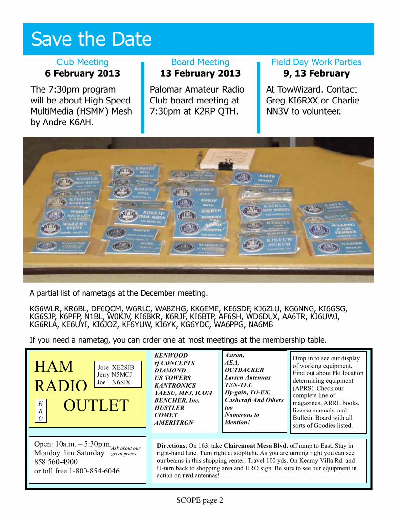
A partial list of nametags at the December meeting.
KG6WlR, KR6Bl, DF6QCM, W6RlC, WA8zHG, KK6eMe, Ke6SDF, Kj6zlu, KG6NNG, KI6GSG, KG6SjP, K6PFP, N1Bl, W0KjV, KI6BKR, K6RjF, KI6BTP, AF6SH, WD6DuX, AA6TR, Kj6uWj, KG6RlA, Ke6uyI, KI6joz, KF6yuW, KI6yK, KG6yDC, WA6PPG, NA6MB
If you need a nametag, you can order one at most meetings at the membership table.

SCOPE page 3
Above: a photo from last week’s lunch Bunch meeting at Fuddrucker’s Hamburgers.
The lunch bunch welcomes all for a friendly Friday lunch. locations vary. An email is sent out on Wednesday with details for the Friday lunch.
Sign up at http://www.w0ni.com
Advertisements are free for membersHave items that need to find a new home? Advertise here! Send your ads to [email protected]
For Sale NEW PRICEHallicrafter SX11 with matching speaker, good condition, works great. $100 oBo [email protected] or 619-224-8948
SCOPE page 4
Progress Report: PTz Camera Controller27 january 2013, Paul Williamson KB5MuThe project to install a commercial-grade surveillance camera on the tower at the repeater site saw some progress this month. Some hardware was modified, some reverse engineering was done, some software development was done, and a big new idea to make the project better was dreamed up.
you can see a photograph of the camera and its manual keypad and joystick controller in the November 2012 issue of the Scope. A more extensive description of the project and photographs of the controller boards are in the November 2011 issue.
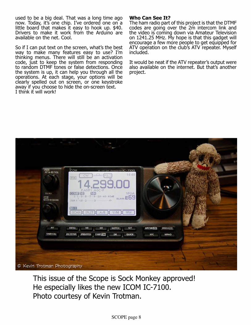
Recall that the controller is a stack of three circuit boards. on the bottom is one of the very popular Arduino microcontroller boards based on an Atmel ATmega328. In the middle is an RS-485 board based on a MAX481CSA to provide the electrical properties required by the control input of the camera. on top is a prototyping board on which I hooked up a MT8870D-1 DTMF decoder chip. Audio from the ATV repeater’s intercom receiver will be connected to the DTMF decoder. When DTMF tones are detected, that event will be detected by the Arduino software and translated into commands to the camera to be transmitted over the RS-485 interface.
RS-485 Board ModificationsRS-485 is an electrical specification for wired digital communication, just as the more familiar RS-232 is. RS-485 uses a single twisted pair of wires to hook up any number of devices. one device at a time can drive the bus, and the drive voltage is applied differentially: when one wire is driven up, the other wire is driven down. The receiver detects only the difference in voltage between the two wires, which helps to reject common-mode noise on the wire. As long as the wire doesn’t fork or loop, and provided it has a matched termination resistor at each end, data transmission should be quite reliable. It’s able to handle distances over 1000 feet and speeds over a million bits per second, far more than we need for this project.
I had occasion to use the same RS-485 interface board on another project last summer. When I hooked up two of them back to back for initial development and testing, they worked fine. But when I built up the whole project, which had nine of them on the same RS-485 bus spread over many
meters of wire with proper termination resistors at each end, I found them to be quite unreliable. Uh oh! That kind of configuration should be well within the capabilities of RS-485. On investigation I found the designers of that board had done something a little too clever.
RS-485 doesn’t say anything about data formats, but it is often used with the same kind of asynchronous byte-oriented serial formats that we’re familiar with on RS-232 serial ports. The ATmega chip on the Arduino board has uSART (universal Synchronous and Asynchronous Receiver and Transmitter) hardware for this kind of format, so that the processor doesn’t have to handle every single bit transition in software. The Arduino software development environment comes with built-in driver support for the USART. So, it’s perfectly reasonable to expect that the user would want to hook up the RS-485 interface to the USART, and indeed the RS-485 board comes wired up that way. But there’s a catch. The uSART doesn’t know anything about sharing a single pair of wires with multiple devices. It’s designed for something like RS-232, where each wire is hooked up to just one driver and the driver is enabled all the time.
The RS-485 interface chip has an extra input pin that is used to enable and disable the driver. It would have been very simple to hook up one of the ATmega’s general purpose output pins to that signal. That would provide a way for the processor to share the RS-485 bus. Unfortunately, the built-in serial drivers don’t know anything about that, so new drivers would have to be written. What’s worse, those drivers would be difficult to get right, since the uSART hardware does not provide any way for software to determine exactly when bits are being actively transmitted. Indeed, the whole point of the USART is to hide that kind of low-level timing from the software. So, the designers of this RS-485 board faced a conundrum. How could they make the board easy to use with the USART?
That’s where they got too clever. They hooked up the enable pin to the transmit data from the uSART, in parallel with the driver’s input pin. That means that the driver would actively drive only the 1 bits of each transmission, and leave the bus undriven for all the 0 bits, as well as between transmissions. How could they hope to get away with that?
It turns out this particular RS-485 chip’s receiver has a feature that’s not required by the RS-485 standard: if the bus isn’t driven, it guarantees that the received value will be seen as a 0. It accomplishes this by having weak pull-up and
SCOPE page 5
pull-down resistors on the bus. So the trick of driving only the 1’s does work, as long as the board is used only with other devices that make the same guarantee, and as long as there aren’t so many other loads on the wire that the weak pullups are too weak to work. My summer project had too many devices on the bus for those weak pullups. Besides, the point of using RS-485 in the first place is to take advantage of the excellent noise immunity of differential signaling. If the bus is only driven for 1 bits, that noise immunity is seriously compromised.
For the summer project, I simply disconnected the enable pin, leaving the transmitter enabled all the time. I could get away with that, because that project had only one master controller that needed to talk to all the other controllers. They didn’t need to talk back. As it happens, we have the same thing on this project. The camera doesn’t talk back on the RS-485 bus, at least not in any documented way I could learn about.
I realized another thing on that summer project. By hooking the RS-485 bus to the one and only uSART on the Arduino, it became impossible to use the uSART for downloading new software to the Arduino, and to use the uSART for printing out debug information during software development. These functions are built into the Arduino software development environment, and they only work using the uSART pins. For the summer project, I manually disconnected the RS-485 bus each time I needed to download code, and I made other arrangements for debugging. It was inconvenient.
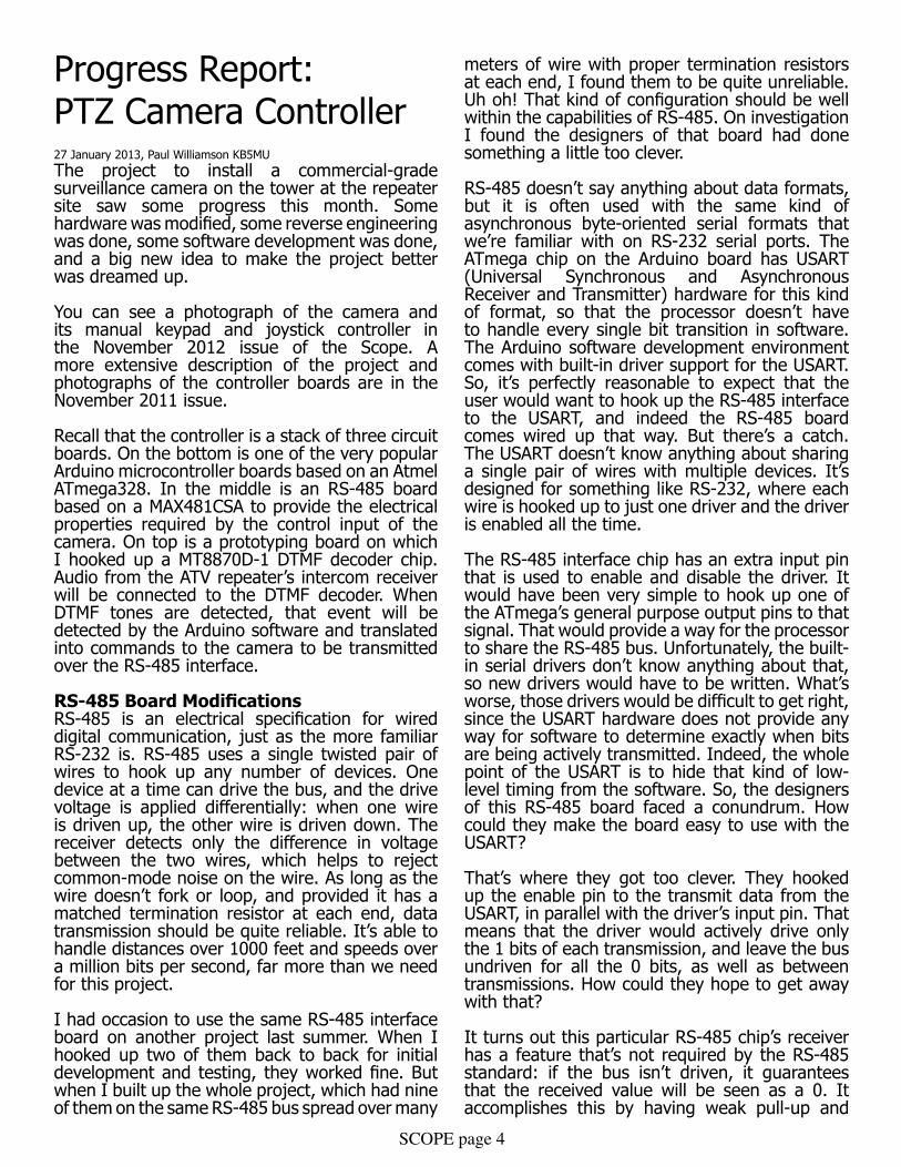
So, for this project, I have opted to modify the RS-485 board so that it does not use the uSART hardware. Instead, the receive data, transmit data, and transmit enable are connected to three separate general purpose pins on the Arduino. This means that the software has to handle each and every bit transition. Fortunately, there is now driver software to handle that, too, built-in to the Arduino environment. The speed requirements for this project are modest at 2400 baud, so the extra processor load of handing
the asynchronous data in software is acceptable. Since the camera doesn’t talk back, we don’t need to worry about careful timing of the transmit enable pin.
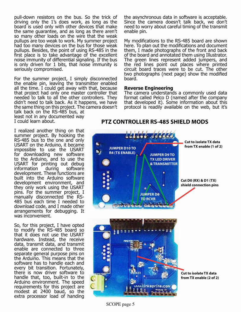
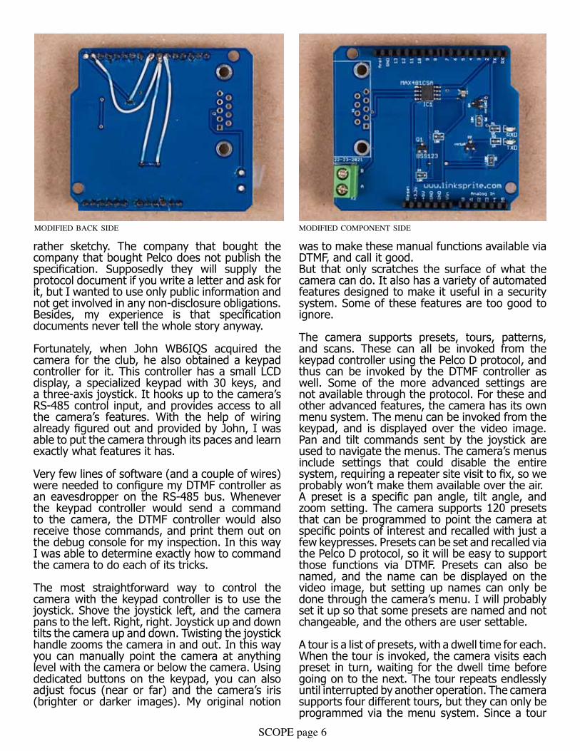
My modifications to the RS-485 board are shown here. To plan out the modifications and document them, I made photographs of the front and back of the board and annotated them using Illustrator. The green lines represent added jumpers, and the red lines point out places where printed circuit board traces were to be cut. The other two photographs (next page) show the modified board.
Reverse EngineeringThe camera understands a commonly used data format called Pelco D (named after the company that developed it). Some information about this protocol is readily available on the web, but it’s
Cut D0 (RX) & D1 (TX)shield connection pins
JUMPER D10 TOR4 (TX ENABLE)
Cut to isolate TX datafrom TX enable (1 of 2)
Cut to isolate TX datafrom TX enable (2 of 2)
JUMPER D9 TOTX LED DRIVER& TRANSMITTER
JUMPER D8 TO RCVR
PTZ CONTROLLER RS-485 SHIELD MODS
SCOPE page 6
rather sketchy. The company that bought the company that bought Pelco does not publish the specification. Supposedly they will supply the protocol document if you write a letter and ask for it, but I wanted to use only public information and not get involved in any non-disclosure obligations. Besides, my experience is that specification documents never tell the whole story anyway.
Fortunately, when john WB6IQS acquired the camera for the club, he also obtained a keypad controller for it. This controller has a small lCD display, a specialized keypad with 30 keys, and a three-axis joystick. It hooks up to the camera’s RS-485 control input, and provides access to all the camera’s features. With the help of wiring already figured out and provided by John, I was able to put the camera through its paces and learn exactly what features it has.
Very few lines of software (and a couple of wires) were needed to configure my DTMF controller as an eavesdropper on the RS-485 bus. Whenever the keypad controller would send a command to the camera, the DTMF controller would also receive those commands, and print them out on the debug console for my inspection. In this way I was able to determine exactly how to command the camera to do each of its tricks.
The most straightforward way to control the camera with the keypad controller is to use the joystick. Shove the joystick left, and the camera pans to the left. Right, right. joystick up and down tilts the camera up and down. Twisting the joystick handle zooms the camera in and out. In this way you can manually point the camera at anything level with the camera or below the camera. using dedicated buttons on the keypad, you can also adjust focus (near or far) and the camera’s iris (brighter or darker images). My original notion
was to make these manual functions available via DTMF, and call it good.But that only scratches the surface of what the camera can do. It also has a variety of automated features designed to make it useful in a security system. Some of these features are too good to ignore.
The camera supports presets, tours, patterns, and scans. These can all be invoked from the keypad controller using the Pelco D protocol, and thus can be invoked by the DTMF controller as well. Some of the more advanced settings are not available through the protocol. For these and other advanced features, the camera has its own menu system. The menu can be invoked from the keypad, and is displayed over the video image. Pan and tilt commands sent by the joystick are used to navigate the menus. The camera’s menus include settings that could disable the entire system, requiring a repeater site visit to fix, so we probably won’t make them available over the air.A preset is a specific pan angle, tilt angle, and zoom setting. The camera supports 120 presets that can be programmed to point the camera at specific points of interest and recalled with just a few keypresses. Presets can be set and recalled via the Pelco D protocol, so it will be easy to support those functions via DTMF. Presets can also be named, and the name can be displayed on the video image, but setting up names can only be done through the camera’s menu. I will probably set it up so that some presets are named and not changeable, and the others are user settable.
A tour is a list of presets, with a dwell time for each. When the tour is invoked, the camera visits each preset in turn, waiting for the dwell time before going on to the next. The tour repeats endlessly until interrupted by another operation. The camera supports four different tours, but they can only be programmed via the menu system. Since a tour
modified component sidemodified back side

SCOPE page 7
would make a very nice general-purpose display on the ATV repeater, we will certainly make an effort to program in some useful tours using the fixed presets.
A pattern is a starting preset plus a series of pans and tilts, all reproduced with the same timing as they were originally entered with. The camera supports four different patterns, and they can be programmed via the protocol. Patterns are probably not as useful as tours, but they can be provided for users to program if they wish.
A scan is a starting preset plus an ending pan angle. The camera pans back and forth between the starting point and the ending point, cylon style, endlessly. The camera supports just one scan. It can be programmed via the protocol, so we can make this available to users, too.
Making all these features available to users will add some complication to the system. The last version of the club’s autopatch system was notorious for being so complicated to use that many users simply gave up. I’d like to avoid that fate. I have some ideas.
Software Development ProgressAs of today (january 27) I have software working that does all the major functions. It recognizes DTMFs. on receiving an activation code of several DTMF codes in sequence, it goes into a manual control mode that simulates joystick operation on the keypad controller.
Refer to any typical DTMF keypad and to the illustration of DTMF keypad functions. The 4 and 6 keys will pan the camera. 2 and 8 will tilt it. 1 and 7 will adjust zoom, while 3 and 9 will adjust focus. For all these functions, just hold the key down as long as you want to keep changing the view. The 0 key will access a single fixed preset in order to get back to a known, identifiable starting point. Finally, the # key will exit keypad mode. This is all pretty simple so far, right? It’s all working now.
I also have DTMF codes that invoke all the fancy features, but they are not easy to remember. I have an idea about that.
The New Crazy IdeaI spent a while trying to design DTMF codes for all the features that were so logical that they’d be easy to remember. The software I have now implements these codes, and I was able to play with them using an actual DTMF keypad. The live keypad mode is very usable, I think. But those DTMF sequences for fancy features? They’re terrible.
I think what’s missing is feedback. even if you can hear the DTMF tone—which I couldn’t with my test setup, and you might not with your HT—you still have no idea what state the system is in until it either does what you want, or fails to. long opaque sequences of DTMF tones aren’t nice.What do we have for feedback to the user? Just the video.
The camera itself has hardware that can put text on the screen over the camera video. It’s even programmable to some extent, using the camera’s menu. But the protocol doesn’t provide a way to just put arbitrary text on the screen. That would have been nice.
So, how hard is it to put text on the screen? That
PRESET0
ZOOMIN
ZOOMOUT
FOCUSFAR
FOCUSNEAR
SPEED
EXIT
SCOPE page 8
used to be a big deal. That was a long time ago now. Today, it’s one chip. I’ve ordered one on a little board that makes it easy to hook up. $40. Drivers to make it work from the Arduino are available on the net. Cool.
So if I can put text on the screen, what’s the best way to make many features easy to use? I’m thinking menus. There will still be an activation code, just to keep the system from responding to random DTMF tones or false detections. once the system is up, it can help you through all the operations. At each stage, your options will be clearly spelled out on screen, or one keystroke away if you choose to hide the on-screen text.I think it will work!
Who Can See It?The ham radio part of this project is that the DTMF codes are going over the 2m intercom link and the video is coming down via Amateur Television on 1241.25 MHz. My hope is that this gadget will encourage a few more people to get equipped for ATV operation on the club’s ATV repeater. Myself included.
It would be neat if the ATV repeater’s output were also available on the internet. But that’s another project.
This issue of the Scope is Sock Monkey approved! He especially likes the new ICOM IC-7100. Photo courtesy of Kevin Trotman.

SCOPE page 9
MinutesPalomar Amateur Radio ClubBoard of Directors MeetingDecember 12, 2012
The meeting was called to order by President Dennis Baca KD6Tuj at 7:30pm at the home of Ron Pollack K2RP. In attendance were:
President: Dennis Baca, KD6TujVice President: Ron Pollack, K2RPSecretary: jim Cooper, Ne6oTreasurer: Teri Bloom, W6TRBDirector #1: Don johnson, WD6FWeDirector #2 Rich lippucci, KI6RRQGuest: Conrad lara, KG6jeIGuest: Dave ochs, KI6lKP
Treasurer’s ReportDave ochs KI6lKP distributed copies of the Treasurer’s Report. Motion by WD6FWe to approve the Treasurer’s Report as published. Seconded by K2RP. Motion passed unanimously.
Secretary’s ReportKB5Mu distributed copies of the minutes of the November board meeting. W6TRB stated that her name was misspelled as Terri instead of Teri. Motion by K2RP to approve the report as modified. Seconded by WD6FWE. Motion passed unanimously.
upcoming General MeetingsKD6Tuj reported that at the january meeting Pat Bunshold WA6MHZ will give a talk on home-brew equipment.
Membership ReportKI6lKP reported that the club has 267 members.
Repeater Technical Report KG6jeI reported that eARS had trouble with echolink not identifying.
KD6Tuj talked with ART KC6uQH about the 6-meter cavities. They are homemade by Bill W6PIG. The Aluminum boxes to BNC connectors have corrosion. The center element needs cleaning and resoldering. There is a possible donation of 47 MHz tunable cavities. Presently, the 6 meter antenna is sitting on the hill.
The 146.73 mystery issues appear to be heat related or intermod.
KD6Tuj wrote a letter to TASMA about interference to the 147.130 repeater by the Contractor Point
repeater on 147.120. This repeater was approved at a different location, then moved to Contractor Point mountaintop.
Appointed OfficersMichelle W5NyV as Scope editor. Al W6GNI as Membership Chairman. Conrad KG6jeI as Repeater Technical Chairman. Motion by K2RP. Seconded by WD6FWe. Motion passed unanimously.
Field Day ChairmanThe Field Day Chairman will be Greg KI6RXX with Charlie NN3V as backup.
Tower MaintenanceNN3V figures the current price to maintain the towers at $180.00. This would replace all cables in the crank-up towers at a price of $0.32/foot, cut to length $0.36/foot. Motion by K2RP to approve up to $200 for tower maintence. Seconded by WD6FWe. Motion passed unanimously.
WD6Tuj is on the lookout for 100 foot lengths of RG213, 9913, or equivalent for each Field Day Station. All hardware should be switched to ¼ inch.
501C3K2RP is working on it using the eARS application as a guide. He should have several years records to work on. WD6FWe suggested that we use Quicken Edition for Non-Profits. A separate account will be required for the 501C funds.
SANDARCKD6Tuj reported that there was no progress on SANDARC.
Next Board Meeting LocationIt was agreed that the next Board meeting will be held at the home of K2RP at 7:30pm on january 9, 2013.
AdjournmentThe meeting was adjourned at 8:50pm
Respectively submittedjim Cooper Ne6oSecretary

SCOPE page 10
New Members the last month or two.
KG6JML, KJ6FZQ, KJ6WNP, KK6AZB, and KJ6STH.And 8 past members Reinstated!
While we certainly appreciate Reinstated members, we believe many “Reinstatements” are due to members not aware that their membership was due. Since many members now get the News Letter (SCOPE) on the web, they don’t receive the paper copy that we mark blue when membership is almost over, and red when the time for renewal has passed.The Board has recommended that we publish member’s calls that are getting close to renewal time. Previously, we listed the memberships that had expired, and some didn’t like that at all!The following members are due for renewal in a month or so. Hopefully, if your call is in this list, you will find time to send a check, or tell PayPal to renew you mem-bership. KJ6TOT, KJ6TOO, KJ6TOP, N6KI, K6EQ, KI6LAV, WA6RDB, ZZ9WGF, KE6CWP, KE6CWM, K2RP, KK6GO, KF6YWE - more next month!
Do you have a mobile installation? Do you want to have a mobile installation, and need some motiva-tion?
We’re looking for a few good mobile installations - whether they’re completed, on the drawing board, or half-way done and tripping you and your passengers every time you get in and out of the vehicle - to be featured in the Scope. We’d love to show your installation.
Tips, narratives, explanations, techniques, problems encountered and solved (or encountered and evaded) are what we’re looking for. Send them in! [email protected]

SCOPE page 11
Look who was in the January issue of QST! Check out Ron’s article starting on page 78.

SCOPEP.O. Box 73 Vista, CA 92085-0073
Return service requested
PERIODICALS POSTAGE PAID AT VISTA CA 92085-9998
Scope (USPS #076530) is published monthly by the Palomar Amateur Radio Club 1651 Mesa Verde Drive, Vista, CA 92084. POSTMASTER: Send address changes to SCOPE, P.O. Box 73, Vista, CA 92085. Periodicals postage paid at Vista, CA 92084. Dues are $20 per year or $35 per year for a family. Dues include a subscription to Scope. You can join or renew your membership on the club’s web site http://www.palomararc.org
Editor: Michelle Thompson W5NYV Submissions: [email protected] Questions? Ideas? Comments? [email protected]
Featured Program: At 7:30pm on the 6th of February 2013, Palomar Amateur Radio Club welcomes Andre N6AH as he presents about HSMM MESH, a 2.4 GHz digital network technology which has applicability for EMCOMM.
About Andre: I am a recently-renewed member of PARC and have presented at PARC meetings in the past on a variety of EMCOMM topics; have written papers on EMCOMM topics including one which was presented at the 2008 ARRL-TAPR Digital Communications Conference. I have placed in the top 3 in class in the ARRL June VHF/UHF (6m thru 10 GHz) Contests in each of the past 3 years. We look forward to seeing you at the Carlsbad Safety Center, 2560 Orion Way, Carlsbad, CA.
SCOPE page 12


![[MS-DTMF]: RTP Payload for DTMF Digits, Telephony Tones](https://img.dokumen.tips/doc/110x75/618761294ef0486d5b31de99/ms-dtmf-rtp-payload-for-dtmf-digits-telephony-tones-.jpg)