Embed Size (px)
Citation preview
(A2LA Cert. No. 1297.01) 04/02/2018 Page 1 of 15
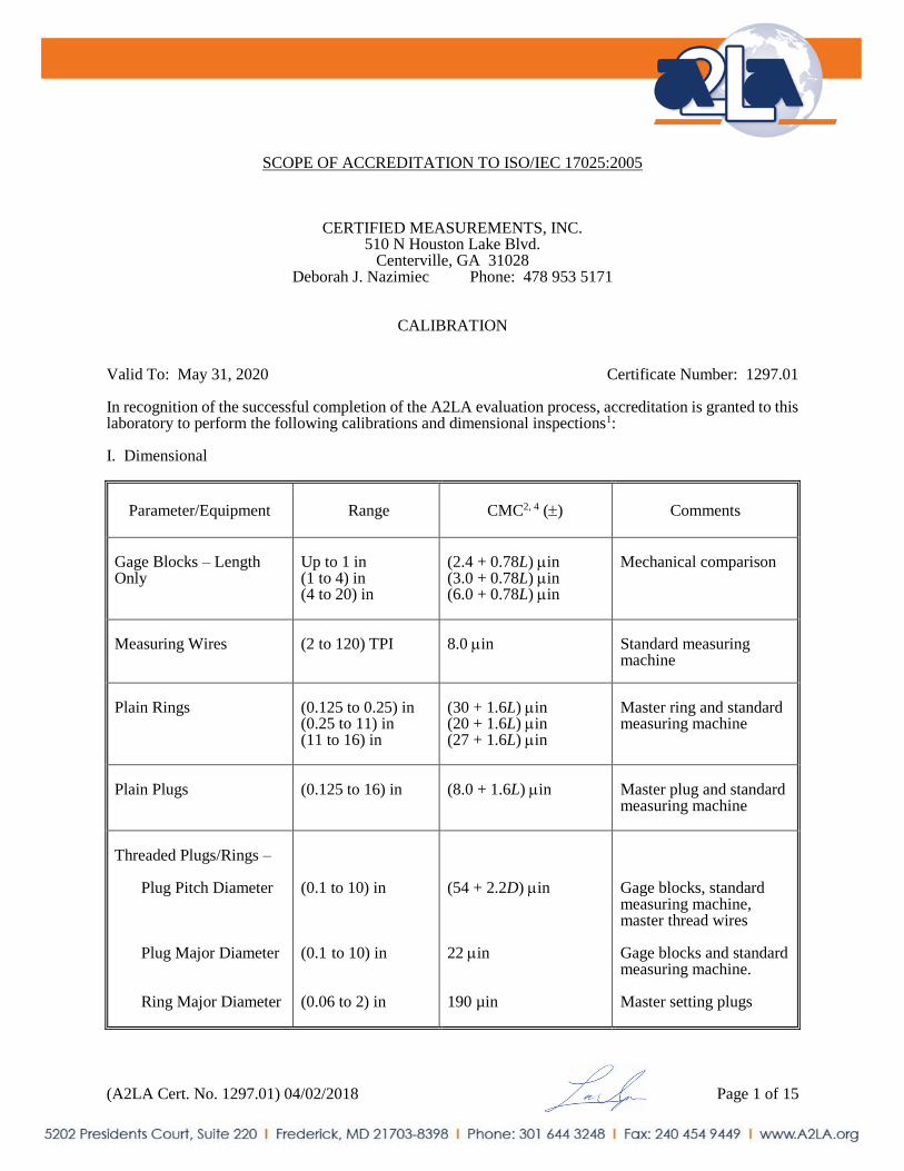
SCOPE OF ACCREDITATION TO ISO/IEC 17025:2005
CERTIFIED MEASUREMENTS, INC. 510 N Houston Lake Blvd.
Centerville, GA 31028 Deborah J. Nazimiec Phone: 478 953 5171
CALIBRATION
Valid To: May 31, 2020 Certificate Number: 1297.01 In recognition of the successful completion of the A2LA evaluation process, accreditation is granted to this laboratory to perform the following calibrations and dimensional inspections1: I. Dimensional
Parameter/Equipment
Range CMC2, 4 () Comments
Gage Blocks – Length Only
Up to 1 in (1 to 4) in (4 to 20) in
(2.4 + 0.78L) in (3.0 + 0.78L) in (6.0 + 0.78L) in
Mechanical comparison
Measuring Wires
(2 to 120) TPI
8.0 in
Standard measuring machine
Plain Rings
(0.125 to 0.25) in (0.25 to 11) in (11 to 16) in
(30 + 1.6L) in (20 + 1.6L) in (27 + 1.6L) in
Master ring and standard measuring machine
Plain Plugs
(0.125 to 16) in
(8.0 + 1.6L) in
Master plug and standard measuring machine
Threaded Plugs/Rings –
Plug Pitch Diameter
Plug Major Diameter
Ring Major Diameter
(0.1 to 10) in (0.1 to 10) in
(0.06 to 2) in
(54 + 2.2D) in 22 in 190 µin
Gage blocks, standard measuring machine, master thread wires Gage blocks and standard measuring machine. Master setting plugs

(A2LA Cert. No. 1297.01) 04/02/2018 Page 2 of 15
Parameter/Equipment
Range CMC2, 4 () Comments
Length Standards
Up to 12 in (12 to 49) in
(19 + 2.9L) in (60 + 3.6L) in
Gage blocks and standard measuring machine
Dial Indicators3
Up to 1 in (1 to 4) in
30 in 250 in
Indicator calibrator
Micrometers3 –
Digital Vernier
Up to 6 in (1 to 36) in
34 in (62 + 2.5L) in
Gage blocks
Tape Measures
(6 to 100) ft
(0.002 + 0.000 04L) in
CMM/master rule
Glass Scales
(3 to 16) in (> 16 to 20) in Up to 3 in
(40 + 1.5L) in (60 + 11L) in 35 in
Standard measuring machine and microscope
Height Measures
(6 to 24) in (> 24 to 48) in
95 in 400 in
Gage amp/probe and gage blocks
Angle Blocks
Up to 45°
2.0”
Sine bar, gage blocks and gage amp/probe
Protractors, Levels and Clinometers
Up to 359°
6.0”
Rotary tilting table
Calipers3
Up to 12 in (12 to 60) in
380 in (620 + 18L) in
Gage blocks and ring gages
Indicating Comparators
0.002 in
11 µin
UMM, American SIP 550M
Steel Rules
Up to 72 in
(0.001 + 0.000 03L) in
Manual CMM
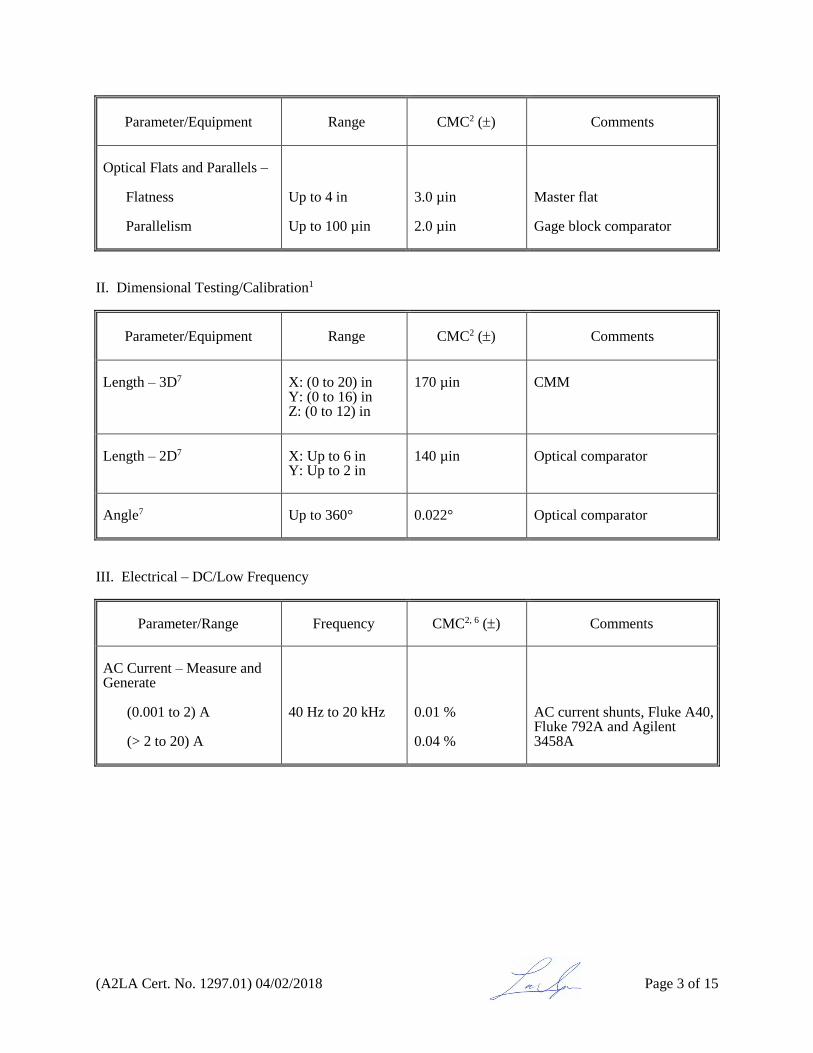
(A2LA Cert. No. 1297.01) 04/02/2018 Page 3 of 15
Parameter/Equipment
Range CMC2 () Comments
Optical Flats and Parallels –
Flatness Parallelism
Up to 4 in Up to 100 µin
3.0 µin 2.0 µin
Master flat Gage block comparator
II. Dimensional Testing/Calibration1
Parameter/Equipment
Range CMC2 () Comments
Length – 3D7
X: (0 to 20) in Y: (0 to 16) in Z: (0 to 12) in
170 µin
CMM
Length – 2D7
X: Up to 6 in Y: Up to 2 in
140 µin
Optical comparator
Angle7
Up to 360°
0.022°
Optical comparator
III. Electrical – DC/Low Frequency
Parameter/Range
Frequency CMC2, 6 () Comments
AC Current – Measure and Generate
(0.001 to 2) A
(> 2 to 20) A
40 Hz to 20 kHz
0.01 % 0.04 %
AC current shunts, Fluke A40, Fluke 792A and Agilent 3458A

(A2LA Cert. No. 1297.01) 04/02/2018 Page 4 of 15
Parameter/Range
Frequency CMC2, 6 () Comments
AC Voltage – Measure and Generate
22 mV (10, 20) mV
220 mV 20 mV 60 mV (100, 200) mV
700 mV (200, 600) mV
2.2 V (0.6, 1, 2) V
7 V (2, 6) V
10 Hz 20 Hz to 20 kHz 50 kHz 10 Hz 20 Hz 40 Hz to 20 kHz 50 kHz 10 Hz 20 Hz 40 Hz to 20 kHz 50 kHz 10 Hz 20 Hz 40 Hz to 20 kHz (50 to 100) kHz (300 to 500) kHz 800 kHz to 1 MHz 10 Hz 20 Hz 40 Hz to 20 kHz (50 to 100) kHz 300 kHz to 1 MHz 10 Hz 20 Hz 40 Hz to 20 kHz (50 to 100) kHz 300 kHz to 1 MHz 10 Hz 20 Hz 40 Hz to 20 kHz (50 to 100) kHz 300 kHz to 1 MHz
0.038 % 0.033 % 0.036 % 0.042 % 0.028 % 0.024 % 0.027 % 0.025 % 0.015 % 0.010% 0.013 % 0.025 % 0.012 % 0.010 % 0.019 % 0.072 % 0.072 % 0.026 % 0.010 % 0.008 % 0.019 % 0.072 % 0.025 % 0.010 % 0.065 % 0.008 % 0.064 % 0.025 % 0.010 % 0.006 % 0.009 % 0.055 %
AC/DC transfer standard 792A with Datron 1271 DMM and Datron 4808 calibrator

(A2LA Cert. No. 1297.01) 04/02/2018 Page 5 of 15
Parameter/Range
Frequency CMC2, 6 () Comments
AC Voltage – Measure and Generate (cont)
22 V (6, 10) V 20 V
70 V (20, 60) V
220 V (60, 100, 200) V
1000 V (200, 600, 1000) V (200, 600, 700) V (1 to 3) V (1 to 10) kV
Measure Only (> 10 to 50) kV
10 Hz 20 Hz 40 Hz to 20 kHz (50 to 100) kHz 300 kHz to 1 MHz 10 Hz 20 Hz 40 Hz to 50 kHz 10 Hz 20 Hz 40 Hz to 20 kHz 50 kHz 10 Hz 20 Hz 40 Hz to 20 kHz 50 kHz 10 Hz 20 Hz 40 Hz to 20 kHz 50 kHz (1 to 13) MHz (13 to 30) MHz (30 to 80) MHz (80 to 100) MHz (30 to 200) Hz (30 to 100) Hz
0.025 % 0.010% 0.007 % 0.010 % 0.056 % 0.025 % 0.010 % 0.070 % 0.025 % 0.010 % 0.007 % 0.010 % 0.025 % 0.012 % 0.008 % 0.010 % 0.025 % 0.012 % 0.008 % 0.01 % 0.14 % 0.29 % 0.58 % 1.4 % 0.30 % 0.40 %
AC/DC transfer standard 792A with Datron 1271 DMM and Datron 4808 calibrator Reference thermal converter Vitrek 4700 Vitrek 4700 w/ HVL-70

(A2LA Cert. No. 1297.01) 04/02/2018 Page 6 of 15
Parameter/Equipment
Range CMC2, 6 () Comments
DC Current – Measure and Generate
0.1 μA to 2 A (2 to 20) A (20 to 100) A
55 A/A 0.03 % 0.07 %
Datron 4808, Datron 1271 Precision shunts, L&N 4300 and Guildline 9711A Valhalla 2555A
DC Voltage – Measure and Generate
Measure Only
100 V to 100 mV 100 mV to 1 V (1 to 10) V 10 V (10 to 100) V (100 to 1000) V (1 to 10) kV (10 to 20) kV (20 to 50) kV
8 V/V + 0.4 V 3.4 V/V + 0.4 V 3.0 V/V + 3.0 V 1.0 V/V 5.0 V/V + 50 V 3.9 V/V + 500 V 0.02 % 0.07 % 0.20 %
Kelvin-Varley divider Fluke 720A Fluke 720A/Fluke 732A Fluke 732A Fluke 752A divider, Fluke 732A and Datron 4808 Vitrek 4700 w/ HVL-70 Vitrek 4700 w/ HVL-70
Resistance – Measure and Generate, Fixed Values
0.001 0.01 0.1 1 10 100 1 k 10 k 100 k 1 M 10 M 100 M
0.01 % 0.01 % 10 µ/ 7.4 µ/ 7.0 µ/ 7.3 µ/ 7.2 µ/ 7.0 µ/ 7.3 µ/ 10 µ/ 12 µ/ 32 µ/
Measurement Intl 9331 series reference standard resistors with Agilent 3458A
Resistance – Measure and Generate, Fixed Values
1 G 10 G 100 G 1 T
0.058 % 0.08 % 0.12 % 0.23 %
Guildline 9520/6500A
Capacitance – Measure and Generate
50 Hz to 1 kHz
(1 to 100) F 100 F to 1 mF
0.1 % 0.15 %
GenRad 1689 capacitance bridge
Capacitance – Measure and Generate @ 1 kHz
11 aF to 1.1 F
0.017 % + 0.000 03 pF
GenRad 1615 capacitance bridge and GenRad 1404-A standard capacitor

(A2LA Cert. No. 1297.01) 04/02/2018 Page 7 of 15
Parameter/Range
Frequency CMC2, 6 () Comments
Inductance – Generate
100 µH to 10 mH (10 to 100) mH 100 mH to 1 H (1 to 10) H
Fixed Point
200 mH
1 kHz 500 Hz 200 Hz 100 Hz 100 Hz, 200 Hz, 400 Hz, 1 kHz, and 10 kHz
2.0 % 1.6 % 0.8 % 0.8 % 0.15 %
GenRad 1491G decade inductor GenRad 1482M std inductor
Inductance3 – Measure
100 μH to 10 H
100 Hz, 200 Hz, 400 Hz, 1 kHz, and 10 kHz
0.20 %
GenRad 1689 RLC Digibridge
Parameter/Equipment
Range CMC2 () Comments
Electrical Simulation of Thermocouple Indicators –
Type E Type J Type K Type N
(-250 to -100) °C (-100 to -25) °C (-25 to 350) °C (350 to 650) °C (650 to 1000) °C (-210 to -100) °C (-100 to -30) °C (-30 to 150) °C (150 to 760) °C (760 to 1200) °C (-200 to 100) °C (-100 to -25) °C (-25 to 120) °C (120 to 1000) °C (1000 to 1372) °C (-200 to -100) °C (-100 to -25) °C (-25 to 120) °C (120 to 410) °C (410 to 1300) °C
0.12 °C 0.16 °C 0.14 °C 0.16 °C 0.21 °C 0.27 °C 0.16 °C 0.14 °C 0.17 °C 0.23 °C 0.33 °C 0.18 °C 0.16 °C 0.26 °C 0.4 °C 0.4 °C 0.22 °C 0.19 °C 0.18 °C 0.27 °C
Fluke 5500A/ ice reference

(A2LA Cert. No. 1297.01) 04/02/2018 Page 8 of 15
Parameter/Equipment
Range CMC2 () Comments
Electrical Simulation of Thermocouple Indicators – (cont)
Type R Type S Type T
(0 to 250) °C (250 to 400) °C (400 to 1000) °C (1000 to 1767) °C (0 to 250) °C (250 to 1000) °C (1000 to 1400) °C (1400 to 1767) °C (-250 to -150) °C (-150 to 0) °C (0 to 120) °C (120 to 400) °C
0.57 °C 0.35 °C 0.33 °C 0.40 °C 0.47 °C 0.36 °C 0.37 °C 0.46 °C 0.63 °C 0.24 °C 0.16 °C 0.14 °C
Fluke 5500A/ ice reference
Electrical Simulation of Thermocouple Indicators3 –
Type E Type J Type K Type T
(-250 to -100) °C (-100 to -25) °C (-25 to 350) °C (350 to 650) °C (650 to 1000) °C (-210 to -100) °C (-100 to -30) °C (-30 to 150) °C (150 to 760) °C (760 to 1200) °C (-200 to 100) °C (-100 to -25) °C (-25 to 120) °C (120 to 1000) °C (1000 to 1372) °C (-250 to -150) °C (-150 to 0) °C (0 to 120) °C (120 to 400) °C
0.58 °C 0.19 °C 0.16 °C 0.19 °C 0.24 °C 0.31 °C 0.19 °C 0.16 °C 0.20 °C 0.27 °C 0.38 °C 0.21 °C 0.19 °C 0.30 °C 0.46 °C 0.73 °C 0.28 °C 0.19 °C 0.16 °C
Fluke 5500A or Fluke 744 process calibrator
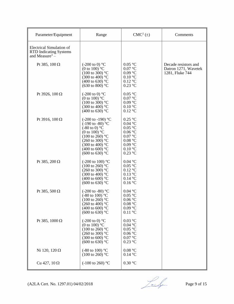
(A2LA Cert. No. 1297.01) 04/02/2018 Page 9 of 15
Parameter/Equipment
Range CMC2 () Comments
Electrical Simulation of RTD Indicating Systems and Measure3 –
Pt 385, 100 Pt 3926, 100 Pt 3916, 100 Pt 385, 200 Pt 385, 500 Pt 385, 1000 Ni 120, 120 Cu 427, 10
(-200 to 0) °C (0 to 100) °C (100 to 300) °C (300 to 400) °C (400 to 630) °C (630 to 800) °C (-200 to 0) °C (0 to 100) °C (100 to 300) °C (300 to 400) °C (400 to 630) °C (-200 to -190) °C (-190 to -80) °C (-80 to 0) °C (0 to 100) °C (100 to 260) °C (260 to 300) °C (300 to 400) °C (400 to 600) °C (600 to 630) °C (-200 to 100) °C (100 to 260) °C (260 to 300) °C (300 to 400) °C (400 to 600) °C (600 to 630) °C (-200 to -80) °C (-80 to 100) °C (100 to 260) °C (260 to 400) °C (400 to 600) °C (600 to 630) °C (-200 to 0) °C (0 to 100) °C (100 to 260) °C (260 to 300) °C (300 to 600) °C (600 to 630) °C (-80 to 100) °C (100 to 260) °C (-100 to 260) °C
0.05 °C 0.07 °C 0.09 °C 0.10 °C 0.12 °C 0.23 °C 0.05 °C 0.07 °C 0.09 °C 0.10 °C 0.12 °C 0.25 °C 0.04 °C 0.05 °C 0.06 °C 0.07 °C 0.08 °C 0.09 °C 0.10 °C 0.23 °C 0.04 °C 0.05 °C 0.12 °C 0.13 °C 0.14 °C 0.16 °C 0.04 °C 0.05 °C 0.06 °C 0.08 °C 0.09 °C 0.11 °C 0.03 °C 0.04 °C 0.05 °C 0.06 °C 0.07 °C 0.23 °C 0.08 °C 0.14 °C 0.30 °C
Decade resistors and Datron 1271, Wavetek 1281, Fluke 744

(A2LA Cert. No. 1297.01) 04/02/2018 Page 10 of 15
Parameter/Equipment
Range CMC2, 6 () Comments
Oscilloscopes3 –
Squarewave Signal – 50 @ 1 kHz 1 M @ 1 kHz
Leveled Sine Wave –
Amplitude (50 kHz ref) Flatness (50 kHz ref)
Time Marker – Measuring Equipment and Period @ 50
Rise Time
1 mV to 6.6 V p-p 1 mV to 130 V p-p 50 kHz reference 50 kHz to 100 MHz (100 to 300) MHz (300 to 600) MHz 50 kHz to 100 MHz (100 to 300) MHz (300 to 600) MHz 5 s to 50 ms 20 ms to 2 ns 1 ns
0.25 % + 40 µV 0.1 % + 40 µV 2.0 % + 300 µV 3.5 % + 300 µV 4.0 % + 300 µV 6.0 % + 300 µV 1.5 % + 100 µV 2.0 % + 100 µV 4.0 % + 100 µV 0.12 % 2.5 µs/s +0 / -500 ps
Fluke 5500A/SC600
IV. Electrical – Microwave/RF
Parameter/Range
Frequency CMC2, 5 () Comments
RF Power –
(1 to 10) mW
(10 to 20) MHz (20 to 50) MHz 50 MHz to 8 GHz (8 to 18) GHz
1.6 % 1.5 % 1.4 % 1.5 %
Tegam F1109 coaxial power standard and Agilent E4418B power meter
RF Attenuation –
(0 to -10) dB -20 dB -30 dB -40 dB -50 dB -60 dB -70 dB -80 dB -90 dB -100 dB
10 MHz to 18 GHz
0.065 dB 0.076 dB 0.092 dB 0.12 dB 0.14 dB 0.16 dB 0.18 dB 0.20 dB 0.47 dB 0.58 dB
Weinschel VM-4A attenuation calibrator

(A2LA Cert. No. 1297.01) 04/02/2018 Page 11 of 15
V. Fluid Quantities
Parameter/Equipment
Range CMC2 () Comments
Hydrometers
(0.7 to 2.0) g/cm3 (sg)
0.000 40 g/cm3 (sg)
Verification of hydrometers in accordance with hydrostatic weighing using Westphall balance
Volumetric Ware –
(To Contain or Deliver)
(1.0 to 10) mL (> 10 to 25) mL (> 25 to 50) mL (> 50 to 100) mL (> 100 to 200) mL (> 200 to 250) mL (> 250 to 500) mL (> 500 to 1000) mL (> 1000 to 2000) mL
0.0054 mL
0.0063 mL
0.0085 mL
0.016 mL
0.026 mL
0.032 mL
0.064 mL
0.13 mL 0.19 mL
NISTIR 7383 SOP #14 by gravimetric determination
Pipettes
10 µL (> 10 to 20) µL (> 20 to 50) µL (> 20 to 100) µL (> 100 to 200) µL (> 200 to 500) µL (> 500 to 1000) µL (> 1000 to 5000) µL
0.19 µL 0.27 µL 0.35 µL 0.48 µL 0.74 µL 1.5 µL 2.8 µL 4.8 µL
NISTIR 7383 SOP #14 by gravimetric determination
VI. Mechanical
Parameter/Equipment
Range CMC2, 5 () Comments
Torque –
Wrenches3, Screwdrivers Watches
Torque Analyzers, Transducers
(0.4 to 1000) ft·lbf (0.6 to 100) in·ozf (1 to 100) in·ozf (5 to 50) in·lbf (50 to 1200) in·lbf (100 to 600) ft·lbf (600 to 1000) ft·lbf
0.47 % 0.33 % 0.053 %
0.049 % 0.046 % 0.049 % 0.068 %
Torque transducers indicator Torque arms with ASTM Class 4 dead weight Torque arms with ASTM Class 4 dead weight
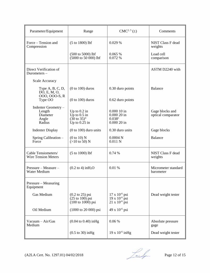
(A2LA Cert. No. 1297.01) 04/02/2018 Page 12 of 15
Parameter/Equipment
Range CMC2, 5 () Comments
Force – Tension and Compression
(5 to 1800) lbf (500 to 5000) lbf (5000 to 50 000) lbf
0.029 % 0.065 % 0.072 %
NIST Class F dead weights Load cell comparison
Direct Verification of Durometers –
Scale Accuracy
Type A, B, C, D, DO, E, M, O, OOO, OOO-S, R Type OO
Indenter Geometry –
Length Diameter Angle Radius
Indenter Display Spring Calibration – Force
(0 to 100) duros (0 to 100) duros Up to 0.2 in Up to 0.5 in (30 to 35)° Up to 0.25 in (0 to 100) duro units (0 to 10) N (>10 to 50) N
0.30 duro points 0.62 duro points 0.000 10 in 0.000 20 in 0.038o
0.000 20 in 0.30 duro units 0.0004 N 0.011 N
ASTM D2240 with Balance Gage blocks and optical comparator Gage blocks Balance
Cable Tensiometers/ Wire Tension Meters
(5 to 1000) lbf
0.74 %
NIST Class F dead weights
Pressure – Measure – Water Medium
(0.2 to 4) inH2O
0.01 %
Micrometer standard barometer
Pressure – Measuring Equipment
Gas Medium
Oil Medium
(0.2 to 25) psi (25 to 100) psi (100 to 1000) psi (1000 to 20 000) psi
17 x 10-6 psi 19 x 10-6 psi 21 x 10-6 psi 49 x 10-6 psi
Dead weight tester
Vacuum – Air/Gas Medium
(0.04 to 0.40) inHg (0.5 to 30) inHg
0.06 % 19 x 10-6 inHg
Absolute pressure gage Dead weight tester

(A2LA Cert. No. 1297.01) 04/02/2018 Page 13 of 15
Parameter/Equipment
Range CMC2 () Comments
Mass
1 mg 2 mg 3 mg 5 mg 10 mg 20 mg 30 mg 50 mg 0.10 g 0.20 g 0.30 g 0.50 g 1.0 g 2.0 g 3.0 g 5.0 g 10.0 g 20.0 g 30.0 g 50.0 g 100 g 200 g 300 g 500 g 1.0 kg 2.0 kg 3.0 kg 5.0 kg 10 kg 20 kg 25 kg 1 oz 2 oz 4 oz 8 oz 1 lb 2 lb 3 lb 5 lb 10 lb 20 lb 30 lb 50 lb
0.60 g 0.58 g 0.60 g 0.70 g 0.80 g 0.75 g 0.80 g 0.90 g 1.1 g 1.2 g 1.2 g 1.5 g 2.2 g 2.5 g 3.4 g 4.0 g 6.3 g 7.8 g 11 g 17 g 29 g 40 g 60 g 90 g 0.17 mg 0.73 mg 2.0 mg 2.9 mg 6.5 mg 10 mg 13 mg 4.2 × 10⁻⁷ oz (0.012 mg) 5.6 × 10⁻⁷ oz (0.016 mg) 8.1 × 10⁻⁷ oz (0.023 mg) 3.9 × 10⁻⁶ oz (0.11 mg) 3.3 × 10⁻⁷ lb (0.15 mg) 4.4 × 10⁻⁷ lb (0.20 mg) 2.6 × 10⁻⁶ lb (1.2 mg) 4.6 × 10⁻⁶ lb (2.1 mg) 7.7 × 10⁻⁶ lb (3.5 mg) 2.9 × 10⁻⁵ lb (13 mg) 3.7 × 10⁻⁵ lb (17 mg) 4.9 × 10⁻⁵ lb (22 mg)
NISTIR 5672 SOP # 5 and SOP# 28 with OIML Class E1 weights
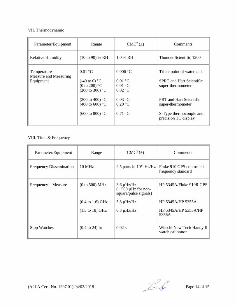
(A2LA Cert. No. 1297.01) 04/02/2018 Page 14 of 15
VII. Thermodynamic
Parameter/Equipment Range CMC2 () Comments
Relative Humidity
(10 to 90) % RH
1.0 % RH
Thunder Scientific 1200
Temperature – Measure and Measuring Equipment
0.01 C (-40 to 0) C (0 to 200) C (200 to 300) C (300 to 400) C (400 to 600) °C (600 to 800) C
0.006 C 0.01 C 0.01 C 0.02 C 0.03 C 0.20 °C 0.71 C
Triple point of water cell SPRT and Hart Scientific super-thermometer PRT and Hart Scientific super-thermometer S-Type thermocouple and precision TC display
VIII. Time & Frequency
Parameter/Equipment
Range CMC2 () Comments
Frequency Dissemination
10 MHz
2.5 parts in 1011 Hz/Hz
Fluke 910 GPS controlled frequency standard
Frequency – Measure
(0 to 500) MHz (0.4 to 1.6) GHz (1.5 to 18) GHz
3.6 µHz/Hz (+ 500 µHz for non-square/pulse signals) 5.8 µHz/Hz 6.3 µHz/Hz
HP 5345A/Fluke 910R GPS HP 5345A/HP 5355A HP 5345A/HP 5355A/HP 5356A
Stop Watches
(0.4 to 24) hr
0.02 s
Witschi New Tech Handy II watch calibrator

(A2LA Cert. No. 1297.01) 04/02/2018 Page 15 of 15
____________________________________________
1 This laboratory offers commercial dimensional testing/calibration service and field calibration service. 2 Calibration and Measurement Capability Uncertainty (CMC) is the smallest uncertainty of measurement
that a laboratory can achieve within its scope of accreditation when performing more or less routine calibrations of nearly ideal measurement standards or nearly ideal measuring equipment. CMCs represent expanded uncertainties expressed at approximately the 95 % level of confidence, usually using a coverage factor of k = 2. The actual measurement uncertainty of a specific calibration performed by the laboratory may be greater than the CMC due to the behavior of the customer’s device and to influences from the circumstances of the specific calibration.
3 Field calibration service is available for this calibration and this laboratory meets A2LA R104 – General Requirements: Accreditation of Field Testing and Field Calibration Laboratories for these calibrations. Please note the actual measurement uncertainties achievable on a customer's site can normally be expected to be larger than the CMC found on the A2LA Scope. Allowance must be made for aspects such as the environment at the place of calibration and for other possible adverse effects such as those caused by transportation of the calibration equipment. The usual allowance for the actual uncertainty introduced by the item being calibrated, (e.g. resolution) must also be considered and this, on its own, could result in the actual measurement uncertainty achievable on a customer’s site being larger than the CMC.
4 In the statement of CMC, L is the numerical value of the nominal length of the device measured in inches; D is the numerical value of the nominal diameter of the device measured in inches.
5 In the statement of CMC, percentage is the percent of reading, unless otherwise noted. 6 The stated measured values are determined using the indicated instrument (see Comments). This
capability is suitable for the calibration of the devices intended to measure or generate the measured value in the ranges indicated. CMCs are expressed as either a specific value that covers the full range or as a percent or fraction of the reading plus a fixed floor specification.
7 This laboratory meets R205 – Specific Requirements: Calibration Laboratory Accreditation Program for
the types of dimensional calibrations listed above. Accredited test reports issued containing appropriate statements of measurement results, measurement uncertainty, and traceability are considered equivalent to a “calibration” certificate.

For the calibrations to which this accreditation applies, please refer to the laboratory’s Calibration Scope of Accreditation.
Accredited Laboratory
A2LA has accredited
CERTIFIED MEASUREMENTS, INC. Centerville, GA
for technical competence in the field of
Calibration
This laboratory is accredited in accordance with the recognized International Standard ISO/IEC 17025:2005 General requirements for the competence of testing and calibration laboratories. This laboratory also meets R205 – Specific Requirements: Calibration Laboratory Accreditation Program. This accreditation demonstrates technical competence for a
defined scope and the operation of a laboratory quality management system (refer to joint ISO-ILAC-IAF Communiqué dated April 2017).
Presented this 2nd day of April 2018. _______________________ President and CEO For the Accreditation Council Certificate Number 1297.01 Valid to May 31, 2020


![03-Kirchner 10 kHz - NASA · From < 60 kHz to > 5 MHz (10 Hz to 50 kHz) 0 1000 2000 3000 4000 5000 6000 0 10000 20000 30000 40000 50000 Repetition Rate [Hz] C-SPAD Dark Noise](https://img.dokumen.tips/doc/110x75/5ecc2242b5cb1834f63f2771/03-kirchner-10-khz-nasa-from-60-khz-to-5-mhz-10-hz-to-50-khz-0-1000.jpg)