Embed Size (px)
Citation preview

SCM820SCM820 Digital IntelliMix Automatic Mixer®
The Shure digital automatic mixer, SCM820, user guide.Version: 4.0 (2021-C)

Shure Incorporated
2/59
Table of Contents
SCM820 SCM820 Digital IntelliMix® Automatic Mixer 4
Overview 4
IntelliMix® Operating Principles 4
Mixer Modes 4
Dual Mixer Operation 5
DFR and Audio Processing 5
Model Variations 5
Hardware Interface 6
Front Panel 6
Rear Panel 8
Signal Path Diagram 11
Operating the Mixer 12
Front Panel Modes 12
Audio Mute and Bypass 13
Monitoring 13
SCM820 Application 15
System Requirements 16
Accessing the SCM820 application 16
Installation 17
Power 17
Rackmounting 17
Typical Audio Connections 18
Configuring the Inputs and Outputs 19
Setting IntelliMix 23
Mixer Mode Descriptions 23
IntelliMix Parameters 26
Selecting the Mixer Mode 26
Single or Dual Mixer Operation 27
Networking 27
Network Overview 28
Digital Audio Networking 29
Dante Software by Audinate 34
Dante Controller 34
Dante Virtual Soundcard 34
Application Examples and Advanced Mixer Settings 34
Creating a Link Group 34
Integrating with Other Systems 35
Advanced Mixer Settings 36
Web conferencing 37
Digital Feedback Reduction (DFR) 38
Function 38
Basic DFR Setup 38
Filter Width 39
SCM820 Application 39
Navigation Bar 40
Input Tab 41
Intellimix Tab 43
Digital Feedback Reduction (DFR) Tab 45
Output Tab 46
Preferences Tab 47
Troubleshooting 49
Front-Panel Error Messages 52
Accessories 52
Furnished Accessories 52
Specifications 53
IP Ports and Protocols 56
Connector Diagrams 57
Shure Incorporated
3/59
IMPORTANT SAFETY INSTRUCTIONS 57
Important Product Information 58
Information to the user 59
Patent Notice 59
Shure Incorporated
4/59
•
••
•
SCM820 SCM820 Digital IntelliMix Automatic Mixer
OverviewThe Shure SCM820 is an 8-channel digital automatic mixer designed for use in speech applications, including sound reinforce-ment, broadcasting and audio recording. It dramatically improves audio quality in any application where multiple microphones are required. The mixer uses IntelliMix technology to select channels to open to the mix bus, while attenuating other channels. The mixing mode is selectable to allow a range of automatic mixing styles.
IntelliMix Operating PrinciplesExpanding upon Shure's classic SCM810 IntelliMix technology, the digital SCM820 delivers seamless automatic mixing by combining the following functions:
Noise Adaptive Threshold (NAT) manages the audio system by distinguishing between dynamic audio (such as speech) and the noise floor (such as air conditioning). It continuously adjusts the activation threshold, so that only speech levels louder than the background noise open a channel.MaxBus ensures that only one channel is opened per sound source, reducing comb filtering for clear, intelligible speech.Number of Open Microphones Attenuation (NOMA) attenuates system gain as additional channels are opened, provid-ing consistent output levels and better gain before feedback.Maintains the perceived ambient sound to achieve a natural sounding audio program even during long pauses in conver-sation.
Mixer ModesThe mixer operates in one of five Mix Modes: Classic, Smooth, Extreme, Custom or Manual. The first three are factory settings that offer a range of reliable automixing styles. IntelliMix is configurable in Custom mode and turned off in Manual mode.
Classic
Classic mode emulates the default settings of the classic Shure SCM810 automixer. It is renowned for fast-acting, seam-less channel gating and consistent perceived ambient sound levels.
Smooth
Smooth mode dynamically balances system gain between open and closed channels. The system gain remains consistent by distributing gain across channels to equal one open channel. This mode incorporates IntelliMix operating principles into a gain sharing mixing style.
Extreme
Extreme is an aggressive variation of Classic mode, configured to achieve maximum gain before feedback by completely attenuating closed channels.
Custom
Custom mode allows individual IntelliMix parameters to be fine-tuned and tailored from the GUI.
Manual
®
®
®

Shure Incorporated
5/59
Manual mode deactivates IntelliMix to operate as a standard mixer. Channel and mix equalization, output limiter and mix bus routing are still active in this setting.
Dual Mixer OperationThe SCM820 can operate as a single or dual mixer:
Single Mixer: Channels are routed to a single mix bus that sends the same audio to both Mix A and B outputs. This allows the same program to be sent to different rooms or recording applications. Output gain, parametric equalizer and limiter can be set separately for each mix.
Dual Mixer: Two separate buses provide independent automixes for each mix output. This allows two entirely different mixes to result from the same set of inputs. This is useful when the mixer is being used for two applications. For example, set Mix A to Classic mode for sound reinforcement, and set Mix B to Smooth for a broadcast feed. As a dual mixer, channels can be routed to Mix A, Mix B, Mix A and B, or neither mix bus.
DFR and Audio ProcessingThe SCM820 features two channels of Digital Feedback Reducer (DFR). DFR uses Shure’s patented Adaptive Notch Filter al-gorithm to detect feedback and deploy up to 16 narrow-band notch filters, dramatically improving gain-before-feedback in a sound reinforcement system. DFR can be applied to any two channels of the SCM820, including the mix outputs.
Additionally, the mixer provides adjustable input equalization, limiting and a parametric output EQ to optimize the sound in any application.
Model VariationsThe following table describes the four SCM820 model variations:
Model Variations
ModelDescription
Connector Type Network Card
SCM820 Block Standard Ethernet
SCM820-DAN Block Dante Digital Audio
SCM820-DB25 DB25 Standard Ethernet
SCM820-DAN-DB25 DB25 Dante Digital Audio

Shure Incorporated
6/59
Upgrading to DanteYou can add digital networking capabilities to a standard SCM820 using the Dante Network Interface Card (A820-NIC-DAN). The card replaces the standard Ethernet port with 2 Dante network ports. This upgrade should only be installed by qualified service personnel.
Update the firmware on the SCM820 before installing the Dante Network Interface Card. Visit www.shure.com for more details.
Hardware InterfaceFront Panel
① Channel Mode SelectionPress the button to select the function of the channel knobs and monitor LED rings. See the Audio Signal Adjustment sec-tion for details on each mode.
② Assignable Channel KnobAdjusts settings and status for each input:
Rotate: Adjusts a setting.
Momentary Press: Solos the channel to the headphone output.
Press and Hold: Mutes the audio or bypasses the EQ setting.
③ Monitor LED Ring13 LED segments display gain setting, input signal meter, IntelliMix gain meter, channel solo, or EQ setting.
④ Channel Status LED
LED Channel Status
Off Channel is closed (attenuated in the automix).
Green Channel is open (selected in the automix).
Amber Channel EQ is bypassed.
Flicker Red Signal is clipping. Set the channel to a lower input gain level.
Solid Red Channel is muted.
⑤ Auxiliary Input Jack (1/8")

Shure Incorporated
7/59
Unbalanced aux input sums left and right channels to mono. Front and back panel aux inputs are summed to a mono signal and routed without automixing to the mix outputs.
⑥ Master Output KnobAdjusts settings and status of the mix outputs. See Front Panel Modes for details.
Rotate: Adjusts output gain or limiter threshold.
Momentary Press: Overrides a soloed channel to return the mix to the headphone output.
Press and Hold: Mutes the audio or bypasses the limiter.
⑦ Master LED RingDisplays gain setting or limiter threshold. A single LED represents each mixer when they are both selected but set to differ-ent levels.
⑧ Master Mode SelectionSelects the function (gain or limiter) of the master knob and LED ring.
⑨ Mix Select ButtonSelects Mix A, Mix B, or both for adjustment with the master knob and monitoring on the LED ring and headphone output. Note: When both Mix A and Mix B are selected, the headphone output only monitors Mix A.
⑩ Mix Status Indicator
LED Mix Status
Green Mix is selected for adjustment and listening on the headphone output.
Amber Limiter is bypassed.
Red Mix is muted.
⑪ Audio Output MetersMonitor the output signal level and limiter threshold for mix A and B.
⑫ LIM (Limiter) LEDsIlluminate amber when the audio levels exceed the limiter threshold.
⑬ System Status IndicatorsThe LEDs illuminate to indicate system settings:
LED Color Status
power Green Unit is powered on.
ethernet Green Unit is connected to a network.
network audio GreenAll connected receive channels are OK (receiving digital audio as expected).
Shure Incorporated
8/59
LED Color Status
Flashing GreenOne or more connected receive channels experiencing a sub-scription error or is unresolved (transmitting device is off, dis-connected, renamed or has incorrect network setting).
Red Clock synchronization problem.
OffNo receive channels connected (routing has not been estab-lished).
automix link
Green Two or more mixers are connected in a link group.
Flashing Green Link Group is configuring.
Off Mixer is in standalone mode.
dual mixerGreen Mixer is set to Dual Mixer operation.
Off Mixer is set to Single Mixer operation.
lockoutRed Front panel controls are locked.
Flashing Red An adjustment is attempted in lockout mode.
⑭ Headphone Volume KnobAdjust the volume of the headphone output.
⑮ Headphone Output Jack (1/4 in.)Monitor a mix or a soloed channel.
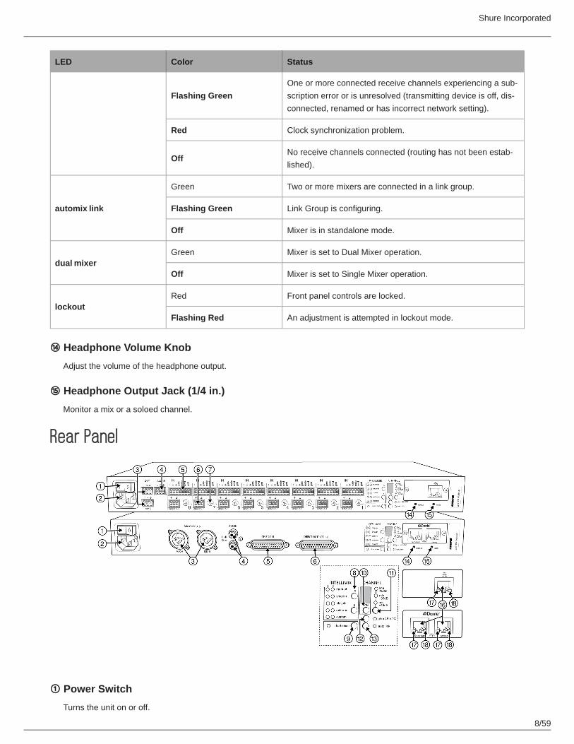
Rear Panel
① Power SwitchTurns the unit on or off.
Shure Incorporated
9/59
② AC Power JackSupplies AC power to the mixer when plugged into a power source.
③ Mix A and Mix B OutputsActive balanced outputs connect to amplifiers, DSP, mixer, or recording device.
④ Auxiliary Input JackUnbalanced aux input sums left and right channels to mono. Front and back panel aux inputs are summed to a mono signal and routed without automixing to the mix outputs.
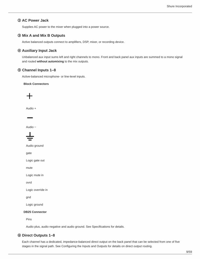
⑤ Channel Inputs 1–8Active-balanced microphone- or line-level inputs.
Block Connectors
Audio +
Audio −
Audio ground
gate
Logic gate out
mute
Logic mute in
ovrd
Logic override in
gnd
Logic ground
DB25 Connector
Pins
Audio plus, audio negative and audio ground. See Specifications for details.
⑥ Direct Outputs 1–8Each channel has a dedicated, impedance-balanced direct output on the back panel that can be selected from one of five stages in the signal path. See Configuring the Inputs and Outputs for details on direct output routing.

Shure Incorporated
10/59
⑦ Chassis Ground Screw 1–8Provides an optional connection for microphone shield wire to chassis ground.
⑧ IntelliMix Select ButtonsScrolls through IntelliMix presets for each mix output. When dual mixer is off, the A button sets the mode for both Mix A and Mix B.
⑨ Dual Mixer ButtonSets the SCM820 as a dual mixer, indicated by the green LED.
⑩ Channel Select Button and DisplayPress to select a single channel (1–8) or all channels (A) when changing input gain or phantom power.
When all channels are selected (A), Input Level and Phantom Power LED indicators only illuminate if all channels have the same setting.L is displayed when the mixer is in lockout mode.
⑪ Input Gain Selection and LED IndicatorSets the analog input gain level for the selected channel(s), illuminating the green LED. All LEDs are off when the channel's audio source is set to Network from the GUI.
⑫ Phantom Power Button and LED IndicatorSupplies 48 VDC phantom power to the selected channel(s), illuminating the green LED. Phantom Power is disabled in the line (+0dB) gain setting.
⑬ Auto Link Button and LED IndicatorEnables networked SCM820-DAN mixers to automatically form a link group. Link Groups enable a larger audio mix by in-corporating inputs from two or more mixers. See Link Groups for more details.
⑭ Lockout Button and LED IndicatorHold for five seconds to disable front and back panel controls. The front panel lockout LED illuminates red (flashing red dur-ing an adjustment attempt) and the back panel channel display shows L.
⑮ Reset ButtonPress and hold for five seconds to reboot the mixer with default system settings restored.
⑯ Network PortsRJ-45 jacks for network connection.
⑰ Network Status LED (Green)
Off = no network link
On = network link established
Flashing = network link active
⑱ Network Speed LED (Amber)

Shure Incorporated
11/59
SCM820:
Off = 10 Mbps
On = 100 Mbps
SCM820-DAN:
Off = 10/100 Mbps
On = 1 Gbps
Signal Path DiagramThe following diagram shows the audio signal path and the routing options for several features (default configuration shown). Use the web application to change the configuration.
Audio Source Selection
AnalogNetwork
Input Meter Mode
Pre-FaderPost-Fader
Headphone Mode (Channel)
Pre-EQPost-Fader

Shure Incorporated
12/59
Mute Control
Pre-IntelliMixPost-IntelliMix
Direct Output Selection
Pre-EQPost-EQPost-FaderIntelliMixIntelliMix NOMA
Operating the MixerFront Panel Modes
Channel InputsThe channel knobs operate in five modes for different types of input signal adjustment and display. Use the front panel mode selection button to select from the following modes.
Channel Gain (gain) Adjust gain within a 128 dB range while displaying the gain setting on the LED ring. Unity gain is at the 9th LED.
Low Cut (low cut) Adjust the frequency of the low cut filter (6 dB/octave from 25 to 320 Hz). Use to remove low-frequency noise such as table vibrations or air-conditioning rumble.
High Shelf (hi shelf) Adjust the high shelf boost or cut (± 12 dB at 5 kHz). Use to add presence to muddy vocals, temper sibilant vocals, or enhance the sound of off-axis lavalier microphones.
Input Signal Meter (ch. me
ter)
LEDs display the input signal level in real-time. Channel gain is adjustable in this mode, and will momentarily display channel gain setting during adjustments.
IntelliMix Gain Meter (gainand ch. meter)
LEDs display the IntelliMix attenuation applied in realtime. Channel gain is adjustable in this mode, displaying the setting on the LEDs during adjustments.

Shure Incorporated
13/59
Mix OutputsThe mix output knob operates in two modes to control the mix output. Use the master function button to select one of two modes.
Output Gain (gain)
Rotate to adjust the output gain of the selected mix. The output signal level is displayed on the meters.
Limiter Threshold (limiter) Rotate to adjust the limiter threshold of the mix (−2 to −50 dBFS). The limiter threshold level is displayed on the meters.
Mode Selector
Audio Mute and BypassMute Channel Input
Press and hold the input channel knob while in gain or ch. meter mode. The channel status LED turns red.
Mute Mix Output
Press and hold the MASTER knob while in gain mode. The mix status LED turns red.
Bypass Input EQ
Press and hold the input channel knob while in low cut or hi shelf mode. The channel status LED turns amber.
Bypass Output Limiter
Press and hold the MASTER knob while in limiter mode. The mix status LED turns amber.
Monitoring
Headphone Output
Shure Incorporated
14/59
Use the front panel headphone jack for monitoring audio. By default, the headphones monitor the mix pre-fader/post-EQ (change to post-fader/post-limiter from GUI > Preferences Tab).
Solo to Headphones
A channel can be soloed to the headphone jack.
Solo Channel
Press a channel knob to solo that channel to the headphones. The other LED rings dim to highlight the soloed channel.
Exit Solo
Press the soloed channel knob or press the Master knob to return the mix to the headphones.
Input MetersThe front panel channel meters can be set to display real-time signal information. Use the front panel mode selection button to scroll to the desired mode:
Input Signal Level
The channel meter mode (ch. meter) displays real-time audio input signal level for each channel.
IntelliMix Gain
The IntelliMix meter mode (gain and ch. meter illuminated) displays IntelliMix gain operation in real-time across the chan-nel LEDs. Channels that gate open will display more gain than channels that are closed (attenuated) in the mix.
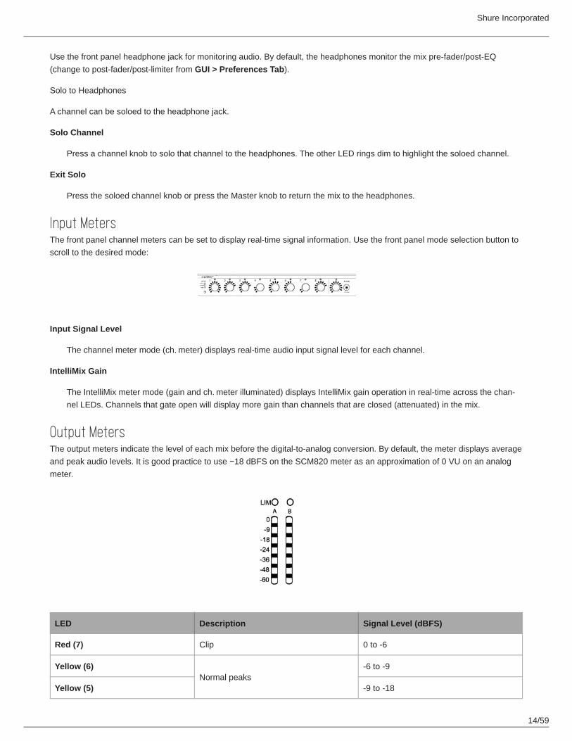
Output MetersThe output meters indicate the level of each mix before the digital-to-analog conversion. By default, the meter displays average and peak audio levels. It is good practice to use −18 dBFS on the SCM820 meter as an approximation of 0 VU on an analog meter.
LED Description Signal Level (dBFS)
Red (7) Clip 0 to -6
Yellow (6)Normal peaks
-6 to -9
Yellow (5) -9 to -18

Shure Incorporated
15/59
••
••••••
LED Description Signal Level (dBFS)
Green (4)
Signal Present
-18 to -24
Green (3) -24 to -36
Green (2) -36 to -48
Green (1) -48 to -60
Changing the Metering TypeGo to the Preferences tab of the GUI to change the following metering options:
Meter Type: Change the input and output meters from displaying VU + Peak (default) to VU or Peak.IntelliMix Gain Metering: The Input tab of the GUI can display input signal level (default) or IntelliMix gain metering in real-time.
SCM820 ApplicationThe SCM820 application enables comprehensive control of the mixer. The application is accessible from any computer. Use the application for the following functions:
Manage mixers from a remote location.Customize IntelliMix parameters.Form large automixes with custom link groups.Assign the direct outputs in the signal path.Configure redundant or split networks.Set up Shure Digital Feedback Reducer (DFR) for up to two channels in each mixer.

Shure Incorporated
16/59
•••
1.2.
1.2.
System RequirementsOperate the control software on computers and mobile devices that meet the following criteria:
Windows 10Microflex Wireless (MXW) application (used for Shure network configuration)Dante Controller (used for network configuration)
Accessing the SCM820 applicationFollow these steps to install the software and access the SCM820 app:
① Get the Shure SCM820 application and the Shure Microflex Wireless (MXW) applicationGet these applications to see devices on the network and open the control interface. Download the software from www.shure.com/software.
② Connect the networkEnsure that the computer and the mixer are on the same network.
③ Launch the Microflex Wireless (MXW) applicationThe application displays all Shure devices on the network.
Locate your SCM820 device on the networkCopy the IP address of your device
④ Access the SCM820 application
Paste the IP or DNS address of the device to the SCM820 applicationPress Connect
⑤ The SCM820 application opens
Shure Incorporated
17/59
••
•••
•••
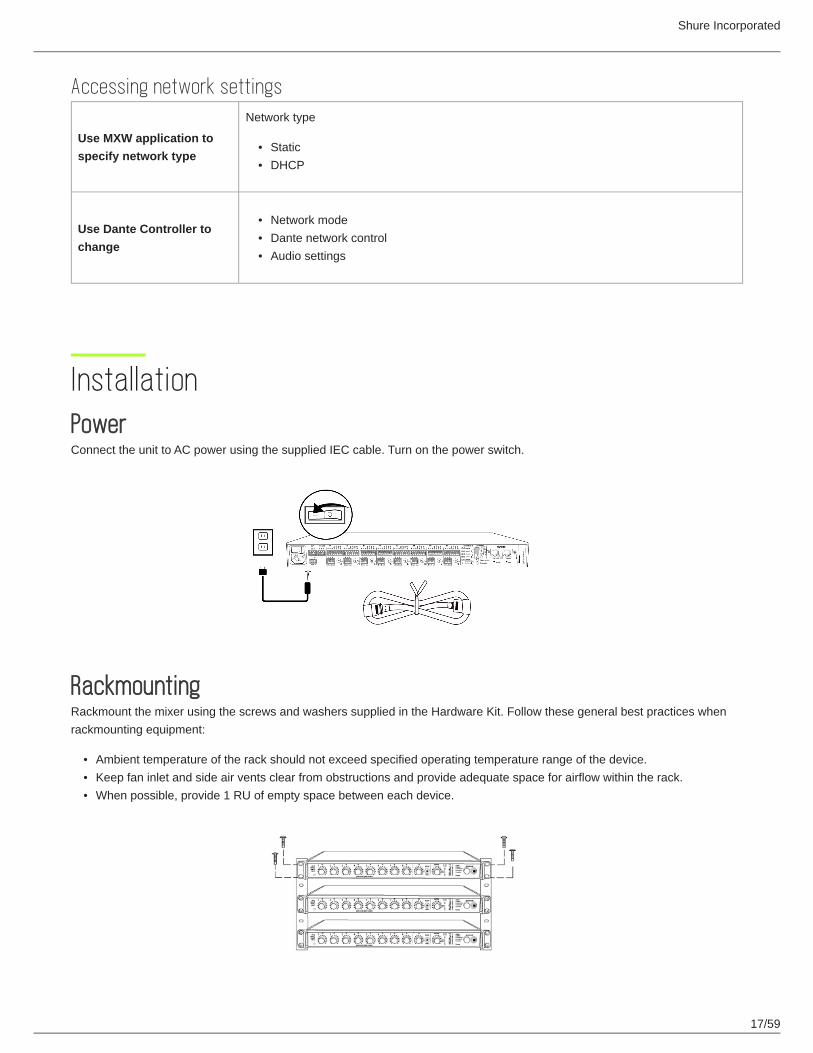
Accessing network settings
Use MXW application to specify network type
Network type
StaticDHCP
Use Dante Controller to change
Network modeDante network controlAudio settings
InstallationPowerConnect the unit to AC power using the supplied IEC cable. Turn on the power switch.
RackmountingRackmount the mixer using the screws and washers supplied in the Hardware Kit. Follow these general best practices when rackmounting equipment:
Ambient temperature of the rack should not exceed specified operating temperature range of the device.Keep fan inlet and side air vents clear from obstructions and provide adequate space for airflow within the rack.When possible, provide 1 RU of empty space between each device.

Shure Incorporated
18/59
Typical Audio Connections① Channel Inputs
MicrophonesInsert send from a mixerDante network audio
② Aux InputsAux-level sound sources:
MP3 playerComputer headphone outputCD player
③ Mix Outputs
AmplifierPowered speakersMixer channel inputs
Shure Incorporated
19/59
•
•
•••
•
•
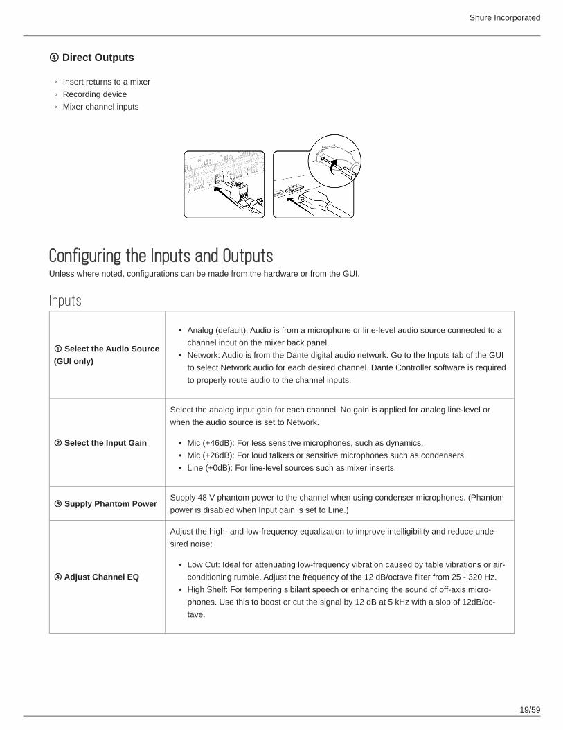
④ Direct Outputs
Insert returns to a mixerRecording deviceMixer channel inputs
Configuring the Inputs and OutputsUnless where noted, configurations can be made from the hardware or from the GUI.
Inputs
① Select the Audio Source (GUI only)
Analog (default): Audio is from a microphone or line-level audio source connected to a channel input on the mixer back panel.Network: Audio is from the Dante digital audio network. Go to the Inputs tab of the GUI to select Network audio for each desired channel. Dante Controller software is required to properly route audio to the channel inputs.
② Select the Input Gain
Select the analog input gain for each channel. No gain is applied for analog line-level or when the audio source is set to Network.
Mic (+46dB): For less sensitive microphones, such as dynamics.Mic (+26dB): For loud talkers or sensitive microphones such as condensers.Line (+0dB): For line-level sources such as mixer inserts.
③ Supply Phantom PowerSupply 48 V phantom power to the channel when using condenser microphones. (Phantom power is disabled when Input gain is set to Line.)
④ Adjust Channel EQ
Adjust the high- and low-frequency equalization to improve intelligibility and reduce unde-sired noise:
Low Cut: Ideal for attenuating low-frequency vibration caused by table vibrations or air-conditioning rumble. Adjust the frequency of the 12 dB/octave filter from 25 - 320 Hz.High Shelf: For tempering sibilant speech or enhancing the sound of off-axis micro-phones. Use this to boost or cut the signal by 12 dB at 5 kHz with a slop of 12dB/oc-tave.

Shure Incorporated
20/59
Hardware Adjustments
Channel Selection
To adjust the Input Gain or Phantom Power, press the CH to scroll to A for All channels, or select a single channel.
Channel Mode Selector
Select a mode to adjust gain or EQ settings.
Mix Mode Selector
Select a mode to adjust output level or limiter threshold.

Shure Incorporated
21/59
GUI Adjustments
Input Tab
Shure Incorporated
22/59
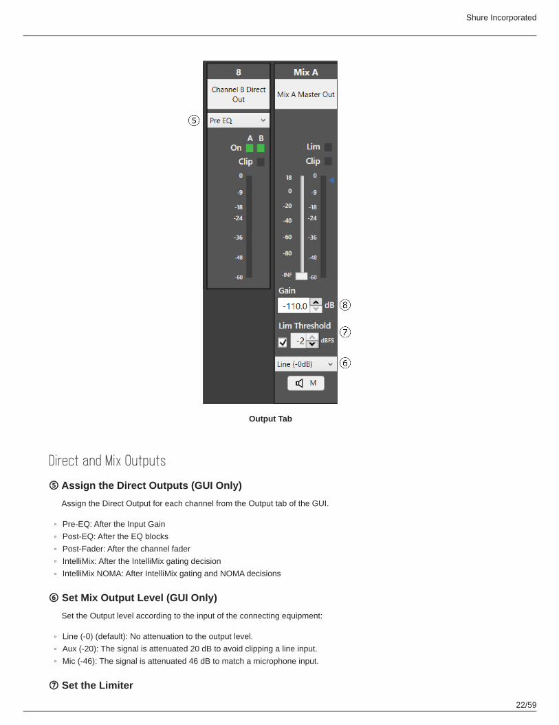
Output Tab
Direct and Mix Outputs
⑤ Assign the Direct Outputs (GUI Only)Assign the Direct Output for each channel from the Output tab of the GUI.
Pre-EQ: After the Input GainPost-EQ: After the EQ blocksPost-Fader: After the channel faderIntelliMix: After the IntelliMix gating decisionIntelliMix NOMA: After IntelliMix gating and NOMA decisions
⑥ Set Mix Output Level (GUI Only)Set the Output level according to the input of the connecting equipment:
Line (-0) (default): No attenuation to the output level.Aux (-20): The signal is attenuated 20 dB to avoid clipping a line input.Mic (-46): The signal is attenuated 46 dB to match a microphone input.
⑦ Set the Limiter

Shure Incorporated
23/59
The output limiter prevents distortion during loud program peaks without affecting normal program levels. This prevents overloading the devices connected to the mixer outputs.
⑧ Adjust the Output GainAdjust the overall output level of the mix.
Auxiliary (Aux) InputThe SCM820 features two auxiliary inputs: an 1/8” jack on the front panel and a back panel input (block connector or RCA con-nectors, depending on the model). Each input sums the left and right channel to a mono signal. This mono signal is routed di-rectly to the mix outputs, bypassing the automixing process. Use this input for sources such as an MP3 player or computer speaker output.
Digital ChannelsWhen the mixer is connected to a Dante network, the left and right channels are accessible before they sum to the mono signal for the mix outputs. Use the Aux L and Aux R channels in Dante Controller to route audio to and from the aux channel.
Setting IntelliMixThe SCM820 uses IntelliMix to select channels to open in a mix, while attenuating the gain of closed channels. IntelliMix is available in three presets to excel in any application where multiple microphones are used at once. In all modes (except Manu-al), MaxBus ensures that only one channel is opened per sound source.
Mixer Mode DescriptionsThe SCM820 features five mix modes: Classic (Default), Extreme, Smooth, Custom or Manual.
ClassicClassic mode emulates the classic Shure SCM810 automixer (in its default settings). It is renowned for fast-acting, seamless channel gating and consistent perceived ambient sound levels. The Classic mode excels in most applications, specifically sound reinforcement and teleconferencing.
Gating Style: Full
Gain Scaling: Fixed
Off Attenuation: −15 dB
Last Mic Lock On: Enabled
Hold Time: 400 ms
NOMA: 3
NOM Max: 8
Channel Gain in Classic Mixer
1 Talker

Shure Incorporated
24/59
Full gain is applied as the channel opens; off attenuation gain is applied to all channels.
2+ Talkers
As additional channels open, NOMA factor decreases the level of all channels.
SmoothSmooth dynamically balances system gain between open and closed channels. The system gain remains consistent by distrib-uting gain across channels to equal one open channel. It incorporates IntelliMix operating principles into a gain sharing mixing style, making it ideal for broadcast and recording applications.
Gating Style: Relative
Gain Scaling: Adaptive
Off Attenuation: Disabled
Last Mic Lock On: Disabled
Tip: Unroute all unused channels to the mix bus. This will ensure the most consistent noise floor in Smooth mode.
Channel Gain in Smooth Mixer
1 Talker
Relative gain is applied to the open channel; all channels adaptively attenuate to maintain system gain.
2+ Talkers
As additional channels open, gain is adaptively distributed across all channels to maintain system gain.

Shure Incorporated
25/59
ExtremeExtreme is an aggressive variation of the Classic mode, configured to achieve maximum gain before feedback by completely attenuating closed channels. Only open channels add to the system levels and ambient sound. Extreme mode is designed for sound reinforcement applications.
Gating Style: Full
Gain Scaling: Fixed
Off Attenuation: −110 dB
Last Mic Lock On: Disabled
Hold Time: 400 ms
NOMA: 3
NOM Max: 8
Channel Gain in Extreme Mixer
1 Talker
Full gain is applied to the open channel. Closed channels are fully attenuated.
2+ Talkers
As additional channels open, NOMA factor decreases the level of all channels.
ManualManual mode deactivates IntelliMix to allow the SCM820 to operate as a standard mixer. All Channel Status LEDs remain on in this mode to indicate there is no IntelliMix attenuation. Channel and mix equalization, output limiter and mix bus routing are still active in this setting.
Tip: Be careful when switching to Manual mode, as all microphones will gate open to full gain, which may result in feedback.
CustomCustom mode allows IntelliMix parameters to be fine-tuned and tailored from the web application. The mixer automatically switches to Custom once a parameter is changed in Classic, Extreme or Smooth mode. Theses configurations are saved to the device and will persist after the mixer is turned off and restarted.

Shure Incorporated
26/59
IntelliMix ParametersGating Style
Determines the way gain is applied to open channels.
Full Channels open at full gain (as adjusted by the NOMA factor).
RelativeChannels open at a gain level that varies with the input signal level—quieter signals receive less gain than loud signals. As the input signal level increases, more gain is applied to the channel.
Gain Scaling
Determines off attenuation and its effect on the total system gain.
FixedOff attenuation is a fixed amount. Total system gain varies with the number of open chan-nels.
AdaptiveOff attenuation is adjusted to maintain a uniform system gain comparable to that of a single open channel.
Off Attenuation: -15 dB The amount of attenuation applied to closed channels.
Last Mic Lock On
Avoids ambient dropout by keeping at least one channel open at all times. The last channel opened remains open until an-other takes its place. (Fixed value based on mixer mode.)
Hold Time
Determines the minimum amount of time that a channel is gated open. (Fixed value = 400 ms)
Number of Open Microphones Attenuation (NOMA)
System gain is attenuated as additional channels are opened in a mix. This is configured per doubling of open channels, adjustable from 1– 6 dB for each mix that has Gain Scaling set to Fixed. (Fixed value = 3)
Maximum Number of Open Microphones (Max NOM)
Identifies the number of microphones that can be open at a time in a mix. (Fixed value = 8).
Note: If you had a previous version of the SCM820 firmware and made changes to these default settings, your specified set-tings are retained. Resetting to factory defaults will use the factory defaults permanently for those settings that have fixed val-ues.
Selecting the Mixer ModePress the Mix A or Mix B button on the mixer back panel to scroll through the five modes. From the IntelliMix tab of the applica-tion, you can select a preset or configure the IntelliMix as a Custom setting.
Mixes A and B have the same IntelliMix settings when the SCM820 is to Single Mixer Operation (default).

Shure Incorporated
27/59
•
•
•••
Single or Dual Mixer OperationThe mixer can be set to perform one or two automixes:
Single Mixer (default): Channels are routed to a single mix bus that sends the same audio to both Mix A and B outputs. Limiter and master gain can still be set independently for both outputs.Dual Mixer: Two separate buses provide independent automixes for each mix output. In this setting, two entirely different mixes can result from the same set of inputs.
Enable dual mixer operation by pressing the Dual Mixer button on the back panel or from the IntelliMix tab in the SCM820 ap-plication.
Example Dual Mixer Applications:Set Mix A to Classic mode for sound reinforcement, and set Mix B to Smooth for a broadcast feed.Mix A to Classic mode for sound reinforcement, and Mix B for Manual for recording.Route channels 1-4 to Mix A and 5-8 to Mix B to run independent automixes for two different locations from one device.
Back Panel
SCM820 application
NetworkingConnect the mixer to a network for hardware control from a Windows computer, transporting digital audio, or using multiple mixers.

Shure Incorporated
28/59
•••
••••
Network OverviewFor most installations, the SCM820 can connect to a computer either directly or though a network switch ("Link-Local" connec-tions). Connect multiple mixers to a switch in a star configuration to ensure reliable networking (each unit connects directly to the switch).
In some cases, computer settings or programs may interfere with the network. The majority of these connection issues can be solved by using a DHCP-enabled router*. Most routers include a DHCP server, while switches do not.
*Note: DHCP servers are not recommended for redundant network configurations. See Redundant Network Recommendations for more details.
Basic Networking RequirementsTo network SCM820 mixers, ensure the setup meets the following requirements:
Use shielded Cat5e cables (or higher)Cable runs limited to 100 m (328 ft.)Devices are on the same subnet
Network Best PracticesUse only one DHCP server per networkAll devices should be on the same subnetTurn off other network interfaces not used to connect to the mixer (including WiFi)All mixers must have the same level of firmware revision installed
Typical Network Setups
Multiple Mixers
Connect multiple mixers together in a star configuration using a DHCP-enabled router for the most reliable network setup.
Single Mixer
The SCM820 can connect directly to a computer. (This setup may take a minute or longer to establish a connection between devices.)
Shure Incorporated
29/59
••••
•••••••
Digital Audio NetworkingDante digital audio is carried over standard Ethernet and operates using standard Internet Protocols. Dante provides low la-tency, tight clock synchronization, and high Quality-of-Service (QoS) to provide reliable audio transport to a variety of Dante de-vices. Dante audio can coexist safely on the same network as IT and control data, or can be configured to use a dedicated net-work.
Data Types on the NetworkThe SCM820 transports two types of data over the network: Shure Control and Dante Audio and Controller. They are transport-ed to/from the two network ports depending on the mixer's network settings.
Shure Control
The Shure Control carries data for the SCM820 application, firmware updates and 3rd party control systems (AMX, Cre-stron). This network is supported by all SCM820 models.
Dante Audio and Controller
The Dante network carries both the digital audio and the control data for Dante Controller. This network is supported by Dante-enabled SCM820s.
Switch Recommendations for Dante NetworkingIn addition to the basic networking requirements, Dante audio networks should use a Gigabit network switch or router with the following features:
Gigabit portsQuality of Service (QoS) with 4 queuesDiffserv (DSCP) QoS, with strict priorityRecommended: A managed switch to provide detailed information about the operation of each network link (port speed, error counters, bandwidth used)
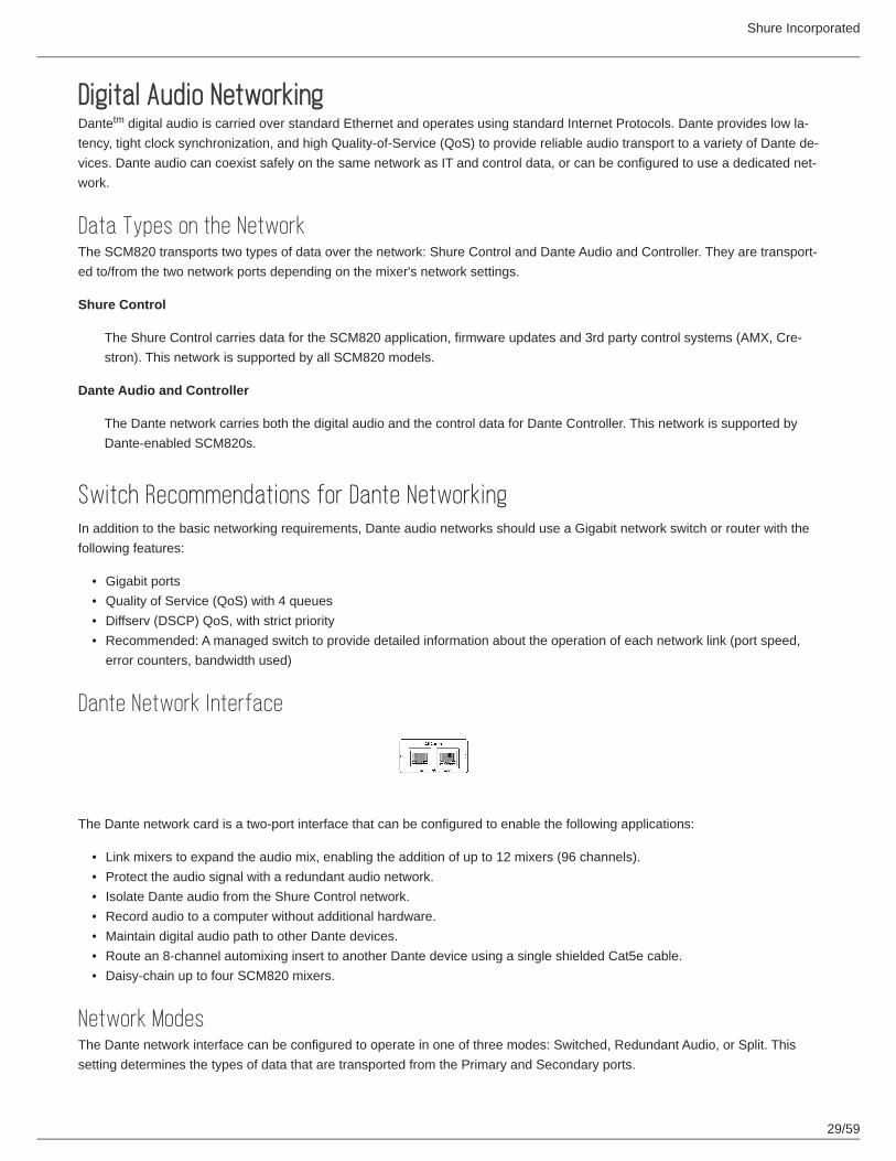
Dante Network Interface
The Dante network card is a two-port interface that can be configured to enable the following applications:
Link mixers to expand the audio mix, enabling the addition of up to 12 mixers (96 channels).Protect the audio signal with a redundant audio network.Isolate Dante audio from the Shure Control network.Record audio to a computer without additional hardware.Maintain digital audio path to other Dante devices.Route an 8-channel automixing insert to another Dante device using a single shielded Cat5e cable.Daisy-chain up to four SCM820 mixers.
Network ModesThe Dante network interface can be configured to operate in one of three modes: Switched, Redundant Audio, or Split. This setting determines the types of data that are transported from the Primary and Secondary ports.
tm
Shure Incorporated
30/59
1.2.3.4.5.6.7.8.
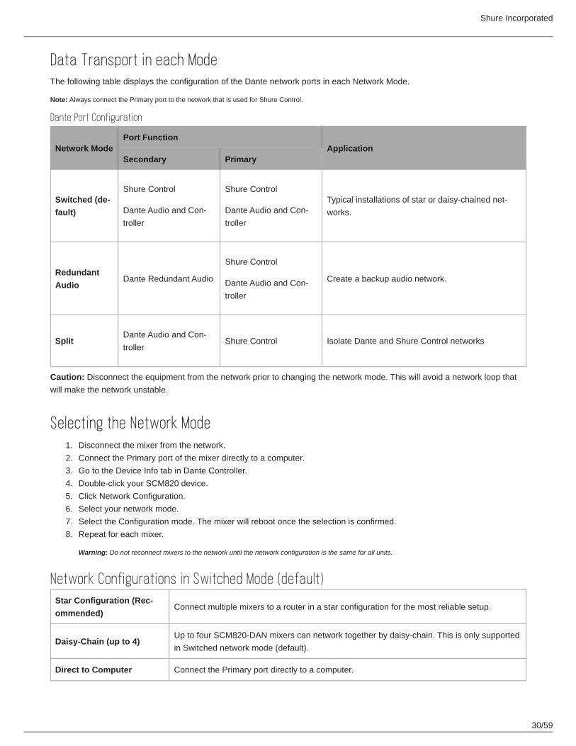
Data Transport in each ModeThe following table displays the configuration of the Dante network ports in each Network Mode.
Note: Always connect the Primary port to the network that is used for Shure Control.
Dante Port Configuration
Network ModePort Function
ApplicationSecondary Primary
Switched (default)
Shure Control
Dante Audio and Con-troller
Shure Control
Dante Audio and Con-troller
Typical installations of star or daisy-chained net-works.
Redundant Audio
Dante Redundant Audio
Shure Control
Dante Audio and Con-troller
Create a backup audio network.
SplitDante Audio and Con-troller
Shure Control Isolate Dante and Shure Control networks
Caution: Disconnect the equipment from the network prior to changing the network mode. This will avoid a network loop that will make the network unstable.
Selecting the Network ModeDisconnect the mixer from the network.Connect the Primary port of the mixer directly to a computer.Go to the Device Info tab in Dante Controller.Double-click your SCM820 device.Click Network Configuration.Select your network mode.Select the Configuration mode. The mixer will reboot once the selection is confirmed.Repeat for each mixer.
Warning: Do not reconnect mixers to the network until the network configuration is the same for all units.
Network Configurations in Switched Mode (default)Star Configuration (Recommended)
Connect multiple mixers to a router in a star configuration for the most reliable setup.
Daisy-Chain (up to 4)Up to four SCM820-DAN mixers can network together by daisy-chain. This is only supported in Switched network mode (default).
Direct to Computer Connect the Primary port directly to a computer.

Shure Incorporated
31/59
Star Configuration (Recommended)
Daisy-Chain
Direct to Computer
Warning: Do Not Make a Network LoopAvoid the following setups that will render the network unusable:

Shure Incorporated
32/59
1.2.
Do not connect the primary to the secondary port of the same device.
Do not connect the two ports to the same switch.
Do not connect mixers together in a loop.
Redundant and Split NetworksThe Primary and Secondary ports require dedicated network switches in Redundant Audio and Split modes.
Isolated Networks for Each Port in Redundancy and Split Modes
Redundant Network RecommendationsFor the most reliable Redundant network, it is recommended to set up both networks without a DHCP server. Connect each unit to a network switch without DHCP or to a router with DHCP disabled.
If it is not possible to disable the DHCP server, configure the mixer to a static IP address:
Disconnect the mixer from the network.Connect the Primary port of the mixer directly to a computer.

Shure Incorporated
33/59
3.4.5.6.7.8.
••
1.2.3.4.5.6.7.8.
Go to the Device Info tab in Dante Controller.Double-click your SCM820 device.Select the Network Configuration tab.Use the Addresses section to specify static IP.The mixer will reboot once the selection is confirmed.Repeat for each mixer.
Warning: Do not reconnect mixers to the network until the network configuration is the same for all units.
Note: Use caution when operating a Link Group in a Redundant network. If a Link Group goes down, there will be temporary audio loss on both ports while the group reconfigures.
Configuring a 100 Mbps Dante networkGigabit equipment is strongly recommended for Dante network. If this is not possible, configure the 100 Mbps network with the following guidelines:
Ensure the router has QoS enabledLatency settings are set to at least 1 ms
Caution: Do not form Link groups on a 100Mbps network, as this will cause increased traffic and will exceed the network bandwidth.
Setting LatencyLatency is the amount of time for a signal to travel across the system to the outputs of a device. To account for variances in la-tency time between devices and channels, Dante has a predetermined selection of latency settings. When the same setting is selected, it ensures that all Dante devices on the network are in sync.
The latency setting for Dante devices should be set according to the number of switches in the network. The SCM820 network card has an internal switch chip and counts as a switch. For example, one SCM820 connected to an external switch equals two switches.
Go to Dante Controller to change the setting.
Disconnect the mixer from the network.Connect the Primary port of the mixer directly to a computer.Go to the Device Info tab in Dante Controller.Double-click your SCM820 device.Select Device Configuration tab.Select the desired Device latency.The mixer will reboot once the selection is confirmed.Repeat for each mixer.
Warning: Do not reconnect mixers to the network until the network configuration is the same for all units.
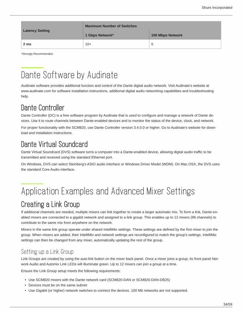
Latency RecommendationsLatency
Latency SettingMaximum Number of Switches
1 Gbps Network* 100 Mbps Network
0.25 ms 3 -
0.5 ms (default) 5 -
1 ms 10 2
Shure Incorporated
34/59
•••
Latency SettingMaximum Number of Switches
1 Gbps Network* 100 Mbps Network
2 ms 10+ 5
*Strongly Recommended
Dante Software by AudinateAudinate software provides additional function and control of the Dante digital audio network. Visit Audinate's website at www.audinate.com for software installation instructions, additional digital audio networking capabilities and troubleshooting help.
Dante ControllerDante Controller (DC) is a free software program by Audinate that is used to configure and manage a network of Dante de-vices. Use it to route channels between Dante-enabled devices and to monitor the status of the device, clock, and network.
For proper functionality with the SCM820, use Dante Controller version 3.4.0.0 or higher. Go to Audinate's website for down-load and installation instructions.
Dante Virtual SoundcardDante Virtual Soundcard (DVS) software turns a computer into a Dante-enabled device, allowing digital audio traffic to be transmitted and received using the standard Ethernet port.
On Windows, DVS can select Steinberg’s ASIO audio interface or Windows Driver Model (WDM). On Mac OSX, the DVS uses the standard Core Audio interface.
Application Examples and Advanced Mixer SettingsCreating a Link GroupIf additional channels are needed, multiple mixers can link together to create a larger automatic mix. To form a link, Dante-en-abled mixers are connected to a gigabit network and assigned to a link group. This enables up to 12 mixers (96 channels) to contribute to the same mix from anywhere on the network.
Mixers in the same link group operate under shared IntelliMix settings. These settings are defined by the first mixer to join the group. When mixers are added, their IntelliMix and network settings are reconfigured to match the group's settings. IntelliMix settings can then be changed from any mixer, automatically updating the rest of the group.
Setting up a Link GroupLink Groups are created by using the auto link button on the mixer back panel. Once a mixer joins a group, its front panel Net-work Audio and Automix Link LEDs will illuminate green. Up to 12 mixers can join a group at a time.
Ensure the Link Group setup meets the following requirements:
Use SCM820 mixers with the Dante network card (SCM820-DAN or SCM820-DAN-DB25)Devices must be on the same subnetUse Gigabit (or higher) network switches to connect the devices. 100 Mb networks are not supported.

Shure Incorporated
35/59
• Ensure the switches have at least 300 Mbps of available bandwidth for each device. Devices in a Link Group use more network bandwidth than Stand Alone devices.
Automatic LinkingThe auto link setting enables SCM820s to automatically form a link group when they join the network. No additional setup from the web application is required.
Select the auto link button on the mixer back panel. It automatically links to other mixers with this function enabled.
Note: Only the first 12 mixers that enable Auto-Link will join the group. If the group is full and an additional mixer attempts to enable Auto Link, it will remain as a Stand-Alone device.
Enable Auto-Linking
Setting Mix Outputs in a Link GroupThe Local/Global setting determines whether each linked SCM820 Mix Output contains only its own program output, or that of all linked mixers. Go to the Output tab of the web application to select the mix output.
Note: The Master level control is independent of the Local/Global setting. The output level and limiter setting of each mixer is affected only by its own Master control.
Global (default)
All linked channels appear at the mixer outputs. This is the default setting for the mixer.
Local
Only its own eight input channels appear at the mixer's Mix Outputs.
Aux ChannelThe aux channel can be set to Local or Global from web application > Inputs Tab. Local Aux keeps the Aux signal from ap-pearing on the mix output of other networked boxes
Integrating with Other Systems
DFR or External EqualizerWhen using DFR channels or setting up a sound system an external processor/equalizer, begin by setting the SCM820 to Manual. This activates (gates open) all channels, so every possible feedback path is open.
After equalizing the sound system and "ringing out" the room with the feedback controller, set the mixer back to an IntelliMix mode.

Shure Incorporated
36/59
1.2.3.4.
1.2.3.4.5.
Shure ULX-D Digital Wireless SystemShure ULX-D Digital Wireless offers uncompromising audio clarity and extremely efficient RF performance with rugged, intelli-gent, encryption-enabled hardware. The SCM820-DAN can provide automixing for the Dual or Quad ULX-D receiver by con-necting to the Dante digital audio network.
As Channel InsertsIntelliMix can be used as a processing insert on an analog console or over the digital audio network. Be sure to set the console inserts to post-fader. If this is not available, be sure to mute audio at the SCM820 in order to remove the signal from the au-tomix.
Analog Insert
Connect the send from the mixer insert to the input of the SCM820.Set the channel input to Line level (+0).Connect return from the mixer insert to the direct output of the SCM820.Set the direct output to IntelliMix NOMA.
Dante Insert
Open Dante Controller software.Route the console sends to the SCM820 inputs.Route the SCM820 direct outputs to the console returns.Set the channel Source to Network from the Inputs tab of the web application.Set the direct output to IntelliMix NOMA on the Outputs tab.
Advanced Mixer SettingsThe logic functions of the SCM820 expand the mixer's range of installation and control options. These functions can be hard-wired or configured in the web application.
The following hardware logic functions are available for each channel:
Gate Out
Follows channel gating and goes to logic "low" (sinks current) when microphone is gated on. 500 mA of current sinking ability is provided.
Mute In
Applying logic "low" (from GATE OUT or a switch closure to logic ground) gates channel off (channel output is fully attenu-ated).
Override In
Applying logic "low" (from GATE OUT or a switch closure to logic ground) forces channel on. When both Mute and Over-ride are activated, Mute takes precedence.
Logic Ground
Logic ground is distinct from the SCM820 audio ground. Make all logic ground connections to this pin, including power supply ground of external logic circuitry. To avoid switch clicks, do not connect logic ground to audio, chassis or rack grounds.
Applications for Improving PerformancesThis section contains suggestions on the uses of the SCM820's logic capabilities. For additional suggestions and solutions to installation problems, contact Shure's Systems Support.
™

Shure Incorporated
37/59
1.
2.
1.2.3.4.5.6.7.8.9.
10.11.
Chairperson-Controlled MutingThe chairperson can, by activating a switch, silence all other microphones and be heard without interruption.
Set the desired channel to Chairperson Mute to manual in the SCM820 application (IntelliMix Panel > Chairperson > Mute).Connect the switch to the Override In logic connection for the chairperson's microphone.
An alternative to a switch is to set the Chairperson Mute to Auto. In this setting, when the chairperson's microphone activates, all other microphones mute automatically.
Remote Channel-Open IndicatorsRemote indicators can be used to indicate when a talker's microphone is on. Connect the LEDs and a 5-volt supply to the GATE OUT pin. To avoid switching clicks in the audio output, do not ground the power supply negative terminal in the audio system or rack ground.
Important: If a single cable is used for the microphone audio signal and the LED dc power, separate shielded pairs must be used. Failure to carry the DC power on a shielded pair may result in audible clicking due to capacitive coupling between the DC power lines and microphone lines.
Disabling the Gating Function (Always On)Select Always On for the channel(s) that should remain open (SCM820 application > IntelliMix Panel > Always On).
Loudspeaker MutingSome applications require a loudspeaker to be placed near each talker to provide audio reinforcement, or to permit telephone conversation or conference monitoring. Each loudspeaker can cause feedback unless it is automatically switched off when the talker near it speaks. To provide this function, connect the GATE OUT terminal of each channel to a separate loudspeaker mut-ing relay.
NOTE: A diode across each relay coil is required to suppress inductive voltage spikes which may damage the SCM820.
An alternative to creating a circuit is a Logic Controlled Relay, such as the Radio Design Labs (RDL) ST‑LCR1.
Web conferencingDante-enabled mixers integrate software applications such as MS Teams , Skype , Zoom , and WebEx . This enables mul-tiple microphones to participate in a teleconferencing event.
Reference the Installation section to properly connect and setup microphones to the mixer back panel.Open the IntelliMix tab of the SCM820 application.Select Dual Mixer operation.In the SCM820 application, route channels 1 - 8 to Mix A only (deselect routing to Mix B).In the Inputs tab of the SCM820 application, route the Aux to Mix B only.Open Dante Virtual Soundcard and turn it on.Open Dante Controller (DC) software.In DC, route the SCM820 tx channel 'Mix A' to computer rx channel 1.In DC, route computer tx channels 1 and 2 to SCM820 rx channels Aux L and R.Connect Mix B analog output to a speaker or output device.Open the computer's settings and select Dante as the input and output soundcard.
Trademarks: Trademarks are the property of their respective owners.
tm tm tm tm

Shure Incorporated
38/59
•
•
1.2.3.4.5.
6.
Digital Feedback Reduction (DFR)DFR uses Shure’s patented Adaptive Notch Filter algorithm to discriminate between feedback and non-feedback sounds. It au-tomatically detects feedback and deploys narrow-band notch filters at the feedback frequencies. DFR filters are narrow enough to prevent any coloration of the audio program.
No sound system (the combination of microphones, mixing, signal processing, power amplifiers, loudspeakers and room acoustics) produces an absolutely flat response. When the level of a sound system is increased, the frequencies at which peaks occur will be the first to exceed the threshold of feedback. The DFR attenuates these frequencies, flattening the re-sponse of the sound system and enabling operation at a higher overall level.
DFR is available for the SCM820 on firmware versions 1.1.0 and higher. For a unit running an earlier firmware version, use the Shure Update Utility application to update the mixer to a new firmware. The application is available from www.shure.com/soft-ware.
FunctionUse DFR as the initial processor on any channel that receives signal from a live microphone where feedback is problematic. When DFR detects feedback, it inserts a shallow, narrow filter into the audio path to reduce gain at the feedback frequency. This filter is called a notch filter, due to the narrow section of the frequency spectrum it affects. The notch automatically deep-ens if feedback continues on that frequency.
Basic DFR SetupDigital Feedback Reducer will not enable you to increase system gain beyond the physical limits of the sound system. In most cases, you reach a point of diminishing returns after five to eight notch filters are set. This is because there are usually only a few dominant peaks in the response of the system. In most cases, you can expect a 6 dB to 9 dB improvement in gain-before-feedback by using the DFR. When you are ringing out the system and notice that many frequencies feedback simultaneously, you have reached the point of diminishing returns. If at this point the system still has insufficient gain before feedback, other changes must be made to the sound system, such as changing the placement of the microphones and/or loudspeakers.
There are two basic ways in which to set-up the DFR to reduce feedback; the Ring-Out Method and the Insurance Policy Method:
Ring Out Method - With this method, you use the DFR as a preemptive measure against feedback for input channels that operate near the feedback point and need an extra margin of stability. Using this method, you raise the channel's gain be-yond its normal setting to deliberately make the system feed back. The DFR will then set the proper filters. Then, when you reduce the input gain to an appropriate level, the system is stable and usable.Insurance Policy Method - With this method, you use the DFR as added insurance against unexpected feedback in an oth-erwise stable system. Simply place the DFR processor in the signal path, without defining any settings. This method is used for systems which already have sufficient gain-before-feedback, but need protection from occasional feedback oc-currences due to non-stationary microphones or user-adjustable gain controls.
To ring out the system:Remove any active filters by clicking the Clear All button.Place microphones at their intended locations.Set the mixer to Manual to open all mics.Slowly raise the gain of the sound system while talking or clapping into the microphones.Assign the DFR to the channel that begins to feed back. If multiple microphones feed back in the same frequency, as-sign the DFR to the mix bus.The DFR processor will deploy notch filters to attenuate the feedback frequencies.

Shure Incorporated
39/59
7.
8.
••••••
Once the system has stopped feeding back, you can continue by further raising the level and repeating the process for additional frequencies. Typically you can raise the gain 3 dB to 9 dB above the level at which feedback first occurred.The remaining (Dynamic) filters will deploy as needed when the system is in use.
Note: Depending on the setup of the sounds system, the main PA signal may be separate from the monitor mix signal. Each feedback path should include a DFR for the maximum gain before feedback.
Assigning DFRTwo DFR blocks are assignable to any channel input or mix output. When using two or less microphones, assign the DFR to those channels to prevent feedback from routing to the mix bus. Additionally, if a microphone is designated for a chairperson or host, DFR should be applied to that channel to ensure that remains stable and does not feed back.
Apply DFR to a mix bus when using multiple non-stationary microphones or when trouble frequencies are feeding back simul-taneously in multiple microphone channels.
Filter WidthThe DFR offers two width options for notch filters. By default, filters in the DFR are deployed as High Q filters. As a high Q filter gets deeper its Q increases up to 101 (1/70th of an octave). You can also set filters to deploy at Low Q. Low Q filters affect a slightly wider range of frequencies by maintaining a Q of 58 (1/40th of an octave) as they deepen. To change the setting for an existing filter, select the Q-Width drop-down menu in the filter row.
New Filter Q: This setting determines the Q width for new Unlocked (Dynamic) frequencies as deployed by DFR.
SCM820 ApplicationThe SCM820 application enables comprehensive control of the mixer. The application is accessible from any computer. Use the application for the following functions:
Manage mixers from a remote location.Customize IntelliMix parameters.Form large automixes with custom link groups.Assign the direct outputs in the signal path.Configure redundant or split networks.Set up Shure Digital Feedback Reducer (DFR) for up to two channels in each mixer.

Shure Incorporated
40/59
•••••
Navigation Bar
Tabs
The control application is separated into tabs for different functions:
Input: Setup and management of input channels 1-8 and AuxIntelliMix: Select the mix mode and load/save customize IntelliMix settingsDFR: Set up and monitor Shure Digital Feedback Reducer (DFR) for up to two channelsOutput: Assign the direct output and manage Mix A and Mix B outputsPreferences: Configure network settings, set the device password, assign metering type, and engage hardware lockout.
Shure Incorporated
41/59
•
•
•••
••
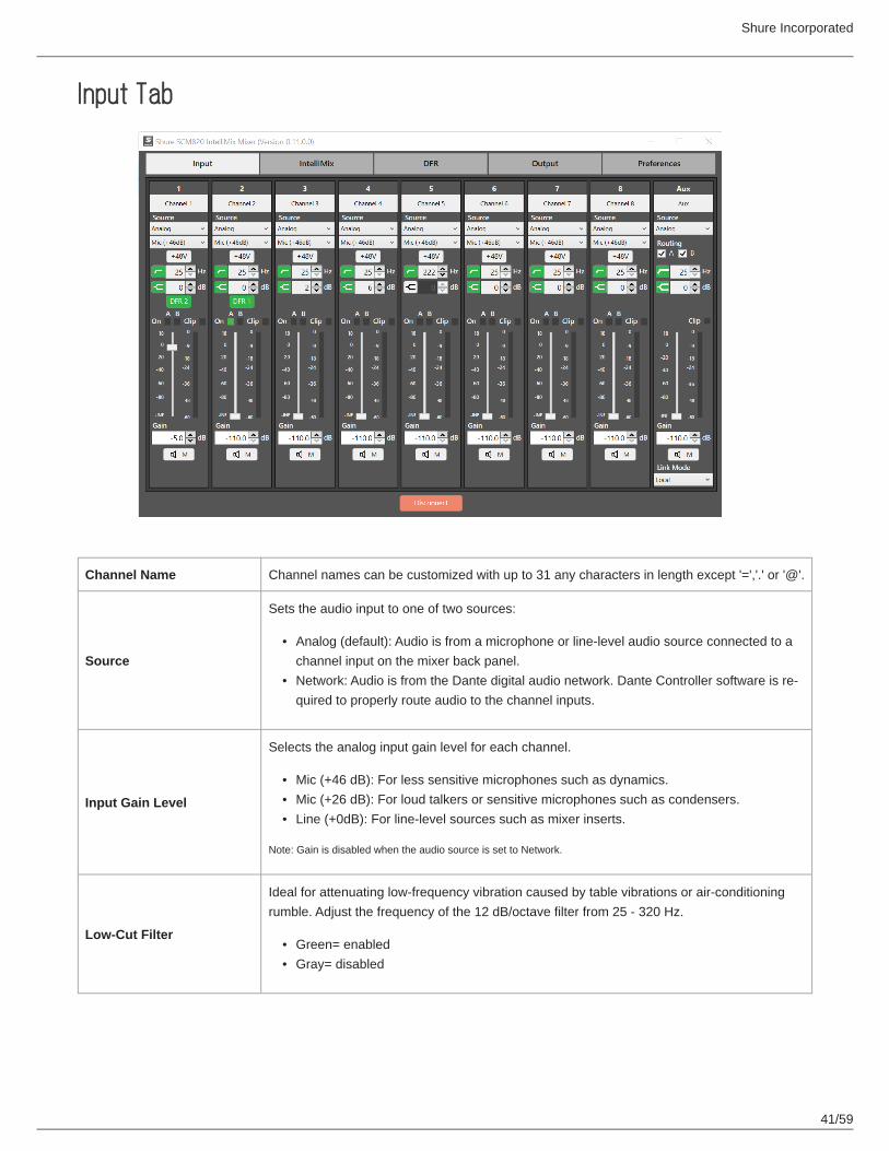
Input Tab
Channel Name Channel names can be customized with up to 31 any characters in length except '=','.' or '@'.
Source
Sets the audio input to one of two sources:
Analog (default): Audio is from a microphone or line-level audio source connected to a channel input on the mixer back panel.Network: Audio is from the Dante digital audio network. Dante Controller software is re-quired to properly route audio to the channel inputs.
Input Gain Level
Selects the analog input gain level for each channel.
Mic (+46 dB): For less sensitive microphones such as dynamics.Mic (+26 dB): For loud talkers or sensitive microphones such as condensers.Line (+0dB): For line-level sources such as mixer inserts.
Note: Gain is disabled when the audio source is set to Network.
Low-Cut Filter
Ideal for attenuating low-frequency vibration caused by table vibrations or air-conditioning rumble. Adjust the frequency of the 12 dB/octave filter from 25 - 320 Hz.
Green= enabledGray= disabled

Shure Incorporated
42/59
••
••
•••
••
••
High-Shelf Filter
For tempering sibilant speech or enhancing the sound of off-axis microphones. Use this to boost or cut the signal by 12 dB at 5 kHz.
Green= enabledGray= disabled
Phantom Power (+48V)
When selected, the button illuminates green to indicate 48 V phantom power is supplied to the microphone. Use this setting for condenser microphones.
Note: Disabled when Input Gain Level is set to Line (+0dB) or Audio Source is set to Network.
DFR Enable/Disable Button
When Digital Feedback Reducer (DFR) is assigned from the DFR tab, an enable/disable button appears in that channel strip.
Green= enabledGray= disabled
Channel On IndicatorsThe two indicators illuminate green when the channel is open to that mix bus (Mix A or Mix B). When set to Dual Mixer, the A and B indicators function separately for each mix.
Clip IndicatorIlluminates when the signal is clipping the input preamp. The light will stay lit as a warning for 2 seconds. Select a lower Input Gain Level to avoid clipping.
Input Meter
Displays signal level information. The meter is customizable for he following options:
Display the input signal level (default) or IntelliMix gain attenuation.Pre-fader or post-fader Input signal level.VU + Peak (default), Peak, or VU metering of input signal level.
Channel Fader and Gain Value
Adjusts the channel volume from -110 dB to +18 dB.
Mute Button
Mutes the audio for that channel. A muted channel still can still be soloed to the headphones for monitoring. Channel Mute Control can be set to one of two places from the IntelliMix tab:
Pre-IntelliMix: Audio is muted before MaxBus or IntelliMix decisions.Post-IntelliMix: Audio is muted after contributing to IntelliMix and Maxbus decisions.
Aux RoutingRoutes the aux channel to the selected mix output. The aux channel routes without automix-ing to the mix outputs.
Aux Link Mode
Defines the aux channel routing when the device is in a Link Group:
Global (default): Aux audio appears at the outputs of all linked mixers.Local: Aux audio appears only at that mixer's output.
Input Meter ModeDetermines if the channel meters are before (Pre-Fader) or after (Post-Fader) the channel's volume knob/fader.
Shure Incorporated
43/59
•
•
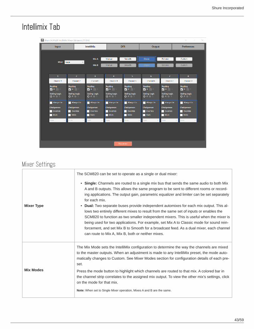
Intellimix Tab
Mixer Settings
Mixer Type
The SCM820 can be set to operate as a single or dual mixer:
Single: Channels are routed to a single mix bus that sends the same audio to both Mix A and B outputs. This allows the same program to be sent to different rooms or record-ing applications. The output gain, parametric equalizer and limiter can be set separately for each mix.Dual: Two separate buses provide independent automixes for each mix output. This al-lows two entirely different mixes to result from the same set of inputs or enables the SCM820 to function as two smaller independent mixers. This is useful when the mixer is being used for two applications. For example, set Mix A to Classic mode for sound rein-forcement, and set Mix B to Smooth for a broadcast feed. As a dual mixer, each channel can route to Mix A, Mix B, both or neither mixes.
Mix Modes
The Mix Mode sets the IntelliMix configuration to determine the way the channels are mixed to the master outputs. When an adjustment is made to any IntelliMix preset, the mode auto-matically changes to Custom. See Mixer Modes section for configuration details of each pre-set.
Press the mode button to highlight which channels are routed to that mix. A colored bar in the channel strip correlates to the assigned mix output. To view the other mix's settings, click on the mode for that mix.
Note: When set to Single Mixer operation, Mixes A and B are the same.

Shure Incorporated
44/59
••
••
Channel StripChannel Name Displays the channel name as defined in the Inputs Tab.
Routing
Routes the channel to the Mix A or Mix B output. The routing options depend on the Mixer Type:
Single Mixer Type: route to both or neither mixe busses.Dual Mixer Type: route to Mix A, Mix B, both, or neither mixe busses.
Gating LogicWhen the mixer is set to Dual Mixer operation, this setting determines whether Mix A or Mix B controls the hardware functions (IntelliMix Direct Output), indicators (Channel Status LEDs) and channel Logic pins.
Always OnThe Always On setting forces a channel to stay open continuously in the mix. Note: A chan-nel that is set to Always On still contributes to and is affected by the IntelliMix. For example, NOMA still applies to Always On channels.
Chairperson
Additional settings can be assigned to the channel(s) for special privileges.
Override:The channel gates open regardless of NOM setting (number of open micro-phones).
Mute:All other channels mute when this channel gates open. There are two types of Chair-person Mute:
Auto: Other channels automatically mute when the selected channel is gated open.Manual: Use a logic-wired button to mute the other microphones.

Shure Incorporated
45/59
••
Digital Feedback Reduction (DFR) Tab
Enable/Disable Button
Click this button to enable or disable the DFR notch filtering. It automatically turns on when DFR is assigned to a channel. When disabled, the DFR filters are turned off.
Green= enabledGray= disabled
Channel Assignment Assign the DFR block to an input channel or mix bus.
Freeze
Click this button to prevent both the deployment of new filters and the automatic adjustment of existing filters. Freeze the DFR to keep it from deploying filters for program material that contains sounds that closely resemble feedback (such as guitar effects, synthesized tones, flute or pipe organ). The button appears lighted in blue when the freeze feature is enabled. During this time, filters remain manually adjustable.
Clear All Clears all settings in the DFR block and reverts all filters back to Unlocked (Dynamic).
Shure Incorporated
46/59
•••••
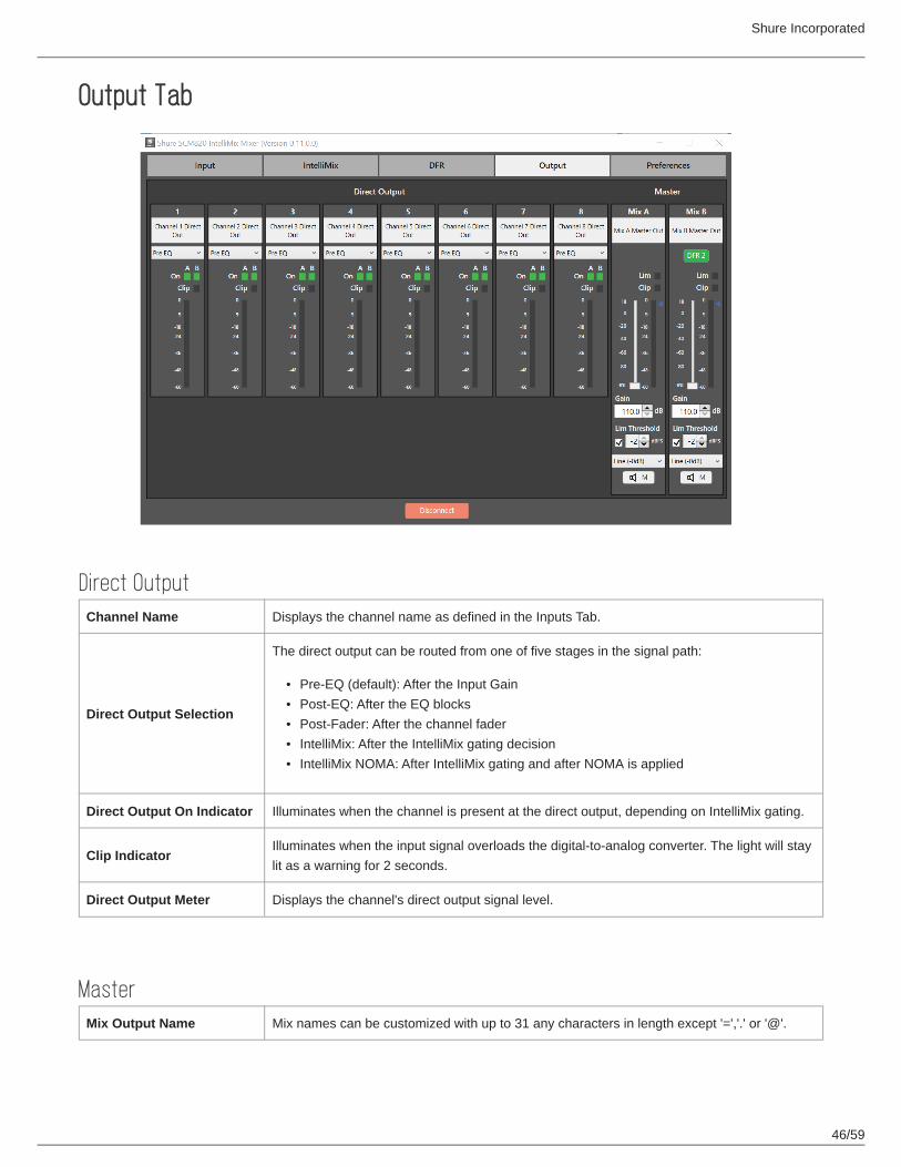
Output Tab
Direct OutputChannel Name Displays the channel name as defined in the Inputs Tab.
Direct Output Selection
The direct output can be routed from one of five stages in the signal path:
Pre-EQ (default): After the Input GainPost-EQ: After the EQ blocksPost-Fader: After the channel faderIntelliMix: After the IntelliMix gating decisionIntelliMix NOMA: After IntelliMix gating and after NOMA is applied
Direct Output On Indicator Illuminates when the channel is present at the direct output, depending on IntelliMix gating.
Clip IndicatorIlluminates when the input signal overloads the digital-to-analog converter. The light will stay lit as a warning for 2 seconds.
Direct Output Meter Displays the channel's direct output signal level.
MasterMix Output Name Mix names can be customized with up to 31 any characters in length except '=','.' or '@'.
Shure Incorporated
47/59
••
••
DFR Enable/Disable Button
When DFR is assigned from the DFR tab, an enable/disable button appears in that channel strip. Select to toggle the state:
Green= enabledGray= disabled
Lim (Limiter) Indicator Illuminates to indicate that the signal has exceed the limiter threshold, engaging the limiter.
Clip Indicator Illuminates when the signal has clipped the outputs, holding for two seconds.
Output Meter Displays the output signal level.
Fader and Gain Value Box Adjusts the mix volume from -110 dB to +18 dB.
Limiter Activation Box Activates the limiter when selected.
Lim ThresholdSet the limiter threshold from -2 to -50 dBFS for the mix outputs. The level is indicated by the blue triangle next to the meter.
Output LevelSelects the output level of the mix outputs. Set according to the input of the connecting equipment. There are three settings: Line (-0dB) (default), Aux (-20dB), Mic (-46dB).
Mute Mutes the audio output for that mix.
Link Mode
Defines the audio content for the mix outputs when the device is in a Link Group.
Global (default): The mixer's outputs contain audio from the entire Link Group.Local: The mixer's outputs contains only the audio from that mixer's inputs.
Preferences TabWarranty Information Read-Only

Shure Incorporated
48/59
•
••
••
DeviceDevice Name Device names can be customized with up to 31 any characters in length except '=','.' or '@'.
Device Serial Number Unique identification of the mixer. Use the number to register the unit at shure.com.
Firmware version Displays the firmware version of the device.
Meter Type
Selects the information displayed on the channel input meters on the Input tab:
VU+Peak (default): Peaks display as a hash bar; average signal levels are displayed as a solid bar.VU: Displays average audio signals.Peak: Displays peak audio signals with a peak hold displayed as a hash bar.
Headphone Mode
Routes audio to the headphone output from one of two stages in the signal path:
Pre Fader (default): Post EQ and pre-volume knob/fader.Post-Fader: Post EQ and post-volume knob/fader. This is post-limiter for the mix adjust-ments.
Enable Software MetersWhen selected, this turns on all metering in the control application. Enabling meters increas-es network traffic. (This does not affect the hardware metering.)
No Lights Mode Turns off all visual indicators on the mixer (except the Power LED on the front panel).
Flash LEDs When clicked, this commands the mixer's LEDs to flash for easy identification.
Shure Incorporated
49/59
1.2.3.4.5.6.7.8.
Reboot Device Reboots the mixer. The mixer will reboot in Standalone mode.
Reset Device to Factory Defaults
Returns the mixer to default factory settings (clearing the password and device and channel names). The mixer will reboot in Standalone mode.
Network
Configuration
Determines the routing of Shure Control and Dante Audio & Controller data from the two net-work ports. See Port Configuration for details. Follow these steps to change the Configura-tion mode:
Disconnect the mixer from the network.Connect the Primary port of the mixer directly to a computer.Go to your Device Info tab in Dante Controller.Double-click your SCM820.Click Network Config.Select the Configuration mode.The mixer will reboot once the selection is confirmed.Repeat for each mixer.
Warning: Do not reconnect mixers to the network until the network settings are the same for all units.
TroubleshootingAudio
Problem Indicator Solution
Distorted audio
Channel Status LED = Flashing Red Set Analog Input to a lower level
Mix Output meter = Clipping Turn down master gain
No Audio/Faint Audio
Channel LEDs in Channel Meter mode (front panel) = Off
Check cablesEnable Phantom power for condenser microphonesCheck Input Gain Level
Mix Output meters = Off Ensure mix is unmutedTurn up Master volume knob

Shure Incorporated
50/59
Problem Indicator Solution
Check channel routing from IntelliMix tab of the web applicationCheck Link Group and Network LEDs (see Link Groups).
Network
Problem Indicator Solution
Can't Connect to the web application
Device not appearing in Shure Web Device Discovery application
Ensure the mixer is poweredProperly connect the Primary port to the computer's networkTurn off other network interfaces not used to connect to the mixer (including WiFi)Check that DHCP server is functioning (if applicable)Ensure Bonjour is running on the PC
Device appears in Shure Discovery application, but web browser cannot connect to the device
Download latest version of Adobe FlashEnsure PC and mixer are on the same subnet
web application is taking a long time to load
Browser opens but the web applica-tion is slow to load
Set the computer gateway to 0.0.0.0Set the router to not send default gateway as a part of DHCPManually set the computer to a static IP address on the same network as the mix-er
web application is slowIndicators are moving slowly or not displaying in real time.
Ensure that five or less windows are open to the same web applicationDisable software meters from web appli-cation Preferences tabSee Network section for properly setting up the network
Network Audio and Link Groups
Problem Indicator Solution
Network audio is missing or distorted
Network Audio LED
Green Check channel and mix gain
Flashing Green Ensure the mixer has a sta-ble network connection

Shure Incorporated
51/59
Problem Indicator Solution
Use Dante Controller soft-ware (DC) to verify channel subscriptions
Red Check master clock in DC
OffUse DC to properly route au-dio channels
No audio output for mixers in a Link Group
AutoMix Link LED
GreenTurn up master gain controlCheck Global/Local setting for the Mix Outputs
Flashing GreenWait until the group has re-configured
Off
Ensure the mixer has been assigned to a Link Group from the Link Group tab of the web application
Hardware
Problem Indicator Solution
Can't make adjustments to the mixer lockout LED = Red
Press and hold lockout button on the back panel for 5 seconds to disable the lockout.If the mixer is still locked, open the web application and uncheck the Hardware Lockout button in the Preferences tab.
No LEDs are turning on Power button = OnUncheck No Lights Mode from the web application Preferences tab
For additional Troubleshooting assistance or further information on complex installations, contact Shure to speak with a support representative. In the Americas region, call Systems Support group at 847-600-8541. For users in other locations, go to www.shure.com to find support contact for your region.
For digital audio networking help, advanced networking guidelines and Dante software troubleshooting, visit Audinate's website at www.audinate.com.
Shure Incorporated
52/59
1.2.3.4.
Front-Panel Error MessagesAn error message is generated on the Channel LED rings when operating or environmental conditions occur that could poten-tially harm the mixer. These types of messages indicate the mixer has experienced a critical failure. Before calling Shure Sys-tem Support, try these basic debugging tools:
Power cycle the device by switching the power button off and on again.Reset the device to factory default settings. This will clear all configurations made to the mixer.Download the latest firmware from Shure.com and load it to the device.If the error message persists, contact a Shure support representative for your region.
Note: To temporarily clear an error message until troubleshooting can be conducted, simultaneously press the Channel 1 knob and Front Panel Mode selector.
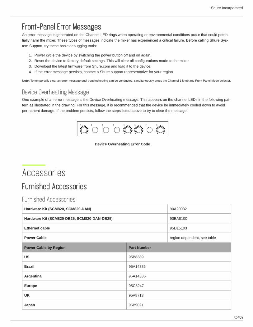
Device Overheating MessageOne example of an error message is the Device Overheating message. This appears on the channel LEDs in the following pat-tern as illustrated in the drawing. For this message, it is recommended that the device be immediately cooled down to avoid permanent damage. If the problem persists, follow the steps listed above to try to clear the message.
Device Overheating Error Code
AccessoriesFurnished Accessories
Furnished AccessoriesHardware Kit (SCM820, SCM820-DAN) 90A20082
Hardware Kit (SCM820-DB25, SCM820-DAN-DB25) 90BA8100
Ethernet cable 95D15103
Power Cable region dependent, see table
Power Cable by Region Part Number
US 95B8389
Brazil 95A14336
Argentina 95A14335
Europe 95C8247
UK 95A8713
Japan 95B9021

Shure Incorporated
53/59
Power Cable by Region Part Number
China 95B9073
Korea 95B9074
Australia 95A9128
SpecificationsAudio Frequency Response20 Hz to 20 kHz (±1 dB)
Dynamic Range20 Hz to 20 kHz, A-weighted, typical
Analog-to-Analog 110 dB
Analog-to-Dante, Dante-to-Analog 113 dB
Output Noise (mix output / direct output)20 Hz to 20 kHz, A-Weighted, one channel open
Line (-0dB) Aux (-20dB) Mic (-46dB)
−90 dBV −110 dBV −135 dBV
Equivalent Input Noise20 Hz to 20 kHz, A-Weighted, input terminated with 150Ω, digital gain at +18 dB
Line (+0dB) Mic (+26dB) Mic (+46dB)
−93 dBV −118 dBV −130 dBV
THD+N1 kHz, +4 dBu out, mix output (MASTER) at +0 dB
<0.05%
Common Mode Rejection Ratio150Ω balanced source, at 1kHz
>70 dB
PolarityNon-inverting, any input to any output
Physical Specifications
Dimensions44 mm x 483 mm x 289 mm (1.7 in. x 19.0 in. x 11.4 in.), H x W x D
Weight5.5 kg (12.0 lbs)

Shure Incorporated
54/59
HousingSteel; Extruded aluminum
Power Requirements100 to 240 V AC, 50-60 Hz, 1 A
Operating Temperature Range−18°C (0°F) to 63°C (145°F)
Storage Temperature Range−29°C (-20°F) to 74°C (165°F)
Analog Connections
Channel Input
Configuration ImpedanceClipping Level
Line (+0dB) Mic (+26dB) Mic (+46dB)
Active Balanced 5 kΩ +20 dBV −6 dBV −26 dBV
Phantom Power48 V DC, selectable per channel, 14 mA
max.
Aux InputConfiguration Impedance Clipping Level
stereo, unbalanced 10 kΩ +10 dBV
Mix Output
Configuration ImpedanceMax Output Level
Line (-0dB) Aux (-20dB) Mic (-46dB)
Active Balanced 350 Ω +20 dBV 0 dBV −26 dBV
Direct OutputConfiguration Impedance Max Output Level
Impedance Balanced 150 Ω +20 dBV
Headphone Output6.35 mm (1/4") TRS, 100 mW, 350 Ω, dual mono (will drive stereo phones)
Digital Signal Processing
AD/DA Converter24-bit, 48 kHz, 113 dB dynamic range

Shure Incorporated
55/59
typical
Internal Processing32-bit
LatencyFrom channel input to mix output, Estimated Nominal, ±0.1 ms
Single Device ( ms) In a Link Group ( ms)
Analog to Analog 0.51 0.76 + 4TN
Analog to Dante 0.29 0.54 + 4TN
Dante to Analog 0.28 + TN 0.53 + 5TN
Dante to Dante 0.06 + TN 0.31 + 5TN
Gain Adjustment Range −110 dB to +18 dB
Low Cut Corner: 25 Hz to 320 HzSlope: 12dB/octave
High Shelf Corner: 5 kHzSlope: 12dB/octaveGain: −18 dB to +18 dB
Gain Adjustment Range −110 dB to +18 dB
Low Shelf Corner: 25 Hz to 20 kHzSlope: 12dB/octaveGain: −18 dB to +18 dB
High Shelf Corner: 25 Hz to 20 kHzSlope: 12dB/octaveGain: −18 dB to +18 dB
6-Band PEQ 25 Hz to 20 kHz, ±18 dBBandwidth: 1/70 to 4octaves
Limiter Ratio: 10:1Threshold: −50dBFS to −2dBFSAttack: 0.1 msDecay: 100 ms
Digital Feedback Reducer (DFR) ProcessingNumber of DFR Blocks 2
Number of Notch Filters 1 to 16 (default)
Notch Filter Bandwidth High Q: 1/70th octave (Q=101)Low Q: 1/40th octave (Q=58)
Notch Filter Depth 0 db to −18 dB in 0.5 dB increments
Networking
Network InterfaceSCM820 Single Port, 10/100 Mbps Ethernet
SCM820-DAN Dual Port, Gigabit Ethernet, Dante digital audio
Cable RequirementsCat 5e or higher, shielded, 100 m maximum
Network Addressing CapabilityDHCP, link-local, static

Shure Incorporated
56/59
IP Ports and Protocols
Shure Control
Port TCP/UDP Protocol DescriptionFactory Default
21 tcp FTP Required for firmware updates (otherwise closed) Closed
22 tcp SSH Not supported Closed
23 tcp Telnet Standard console interface Closed
68 udp DHCP Dynamic Host Configuration Protocol Open
80* tcp HTTP Required to launch embedded web server Open
427 tcp/udp SLP Required for inter-device communication Open
443 tcp HTTPS Not supported Closed
161 tcp SNMP Not supported Closed
162 tcp SNMP Not supported Closed
2202 tcp ASCII Required for 3rd party control strings Open
5353 udp mDNS Required for device discovery Open
5568 udp SDT Required for inter-device communication Open
8023 tcp Telnet Debug console interface Password
8427 udp Multcast SLP Required for inter-device communication Open
64000 tcp Telnet Required for Shure firmware update Open
Dante Audio & Controller
Port TCP/UDP Protocol Description
162 udp SNMP Used by Dante
[319-320]* udp PTP Dante clocking
4321, 14336-14600
udp Dante Dante audio
[4440, 4444, 4455]*
udp Dante Dante audio routing
5353 udp mDNS Used by Dante
[8700-8706, 8800]*
udp Dante Dante Control and Monitoring
†
†
†
†
†
†

Shure Incorporated
57/59
Port TCP/UDP Protocol Description
8751 udp Dante Dante Controller
16000-65536 udp Dante Used by Dante
*These ports must be open on the PC or control system to access the device through a firewall.
These protocols require multicast. Ensure multicast has been correctly configured for your network.
Connector Diagrams
DB25 Connectors
DB25 Connector Models
Block Connector Models
†

Shure Incorporated
58/59
1.2.3.4.5.6.7.
8.
9.
10.
11.12.
13.14.
15.
16.17.18.
19.20.21.
IMPORTANT SAFETY INSTRUCTIONSREAD these instructions.KEEP these instructions.HEED all warnings.FOLLOW all instructions.DO NOT use this apparatus near water.CLEAN ONLY with dry cloth.DO NOT block any ventilation openings. Allow sufficient distances for adequate ventilation and install in accordance with the manufacturer’s instructions.DO NOT install near any heat sources such as open flames, radiators, heat registers, stoves, or other apparatus (in-cluding amplifiers) that produce heat. Do not place any open flame sources on the product.DO NOT defeat the safety purpose of the polarized or grounding type plug. A polarized plug has two blades with one wider than the other. A grounding type plug has two blades and a third grounding prong. The wider blade or the third prong are provided for your safety. If the provided plug does not fit into your outlet, consult an electrician for replace-ment of the obsolete outlet.PROTECT the power cord from being walked on or pinched, particularly at plugs, convenience receptacles, and the point where they exit from the apparatus.ONLY USE attachments/accessories specified by the manufacturer.USE only with a cart, stand, tripod, bracket, or table specified by the manufacturer, or sold with the apparatus. When a cart is used, use caution when moving the cart/apparatus combination to avoid injury from tip-over.
UNPLUG this apparatus during lightning storms or when unused for long periods of time.REFER all servicing to qualified service personnel. Servicing is required when the apparatus has been damaged in any way, such as power supply cord or plug is damaged, liquid has been spilled or objects have fallen into the apparatus, the apparatus has been exposed to rain or moisture, does not operate normally, or has been dropped.DO NOT expose the apparatus to dripping and splashing. DO NOT put objects filled with liquids, such as vases, on the apparatus.The MAINS plug or an appliance coupler shall remain readily operable.The airborne noise of the Apparatus does not exceed 70dB (A).Apparatus with CLASS I construction shall be connected to a MAINS socket outlet with a protective earthing connec-tion.To reduce the risk of fire or electric shock, do not expose this apparatus to rain or moisture.Do not attempt to modify this product. Doing so could result in personal injury and/or product failure.Operate this product within its specified operating temperature range.
This symbol indicates that dangerous voltage constituting a risk of electric shock is present within this unit.
This symbol indicates that there are important operating and maintenance instructions in the literature accom-panying this unit.
Important Product InformationThe equipment is intended to be used in professional audio applications.

Shure Incorporated
59/59
1.2.
••••
••
Note: This device is not intended to be connected directly to a public internet network.
EMC conformance to Environment E2: Commercial and Light Industrial. Testing is based on the use of supplied and recommended cable types. The use of other than shielded (screened) cable types may degrade EMC performance.
Changes or modifications not expressly approved by Shure Incorporated could void your authority to operate this equipment.
Industry Canada ICES-003 Compliance Label: CAN ICES-3 (B)/NMB-3(B)
Authorized under the verification provision of FCC Part 15B.
Please follow your regional recycling scheme for batteries, packaging, and electronic waste.
Information to the userThis device complies with part 15 of the FCC Rules. Operation is subject to the following two conditions:
This device may not cause harmful interference.This device must accept any interference received, including interference that may cause undesired operation.
Note: This equipment has been tested and found to comply with the limits for a Class B digital device, pursuant to part 15 of the FCC Rules. These limits are designed to provide reasonable protection against harmful interference in a residential installa-tion. This equipment generates uses and can radiate radio frequency energy and, if not installed and used in accordance with the instructions, may cause harmful interference to radio communications. However, there is no guarantee that interference will not occur in a particular installation. If this equipment does cause harmful interference to radio or television reception, which can be determined by turning the equipment off and on, the user is encouraged to try to correct the interference by one or more of the following measures:
Reorient or relocate the receiving antenna.Increase the separation between the equipment and the receiver.Connect the equipment to an outlet on a circuit different from that to which the receiver is connected.Consult the dealer or an experienced radio/TV technician for help.
Patent NoticeU.S. patent numbers
5,999,6318,644,477