Embed Size (px)
Citation preview

SBA
ility Services Engine based on ch port. This information can then be th other contextual information such as ocation identifier numbers (ELINs).
and postal information for a physical treet or road name, community, and l, institutional, and industrial buildings 004). An emergency location identifier d by the local public safety answering ation of the caller in a master database n (ALI) database. The ELIN also allows r directly in the event the phone call is
rvices, refer to the following URL: s340/ns394/ns348/ns788/solution_o
ware Services across its application ategories, as shown in Figure 1.
e Services
tilize Cisco Context-Aware Services obile assets that possess embedded co Compatible Extensions compliant itored when they enter and exit both ns can be generated when monitored enter. Examples of how zone or environment include:
re intworkt?
2275
88
This document focContext-Aware Seintegrating into theto producing scalacan be seen to pro
Note that while thisubject matter beion Cisco Context-Engine in general.reader should refethroughout this do
Introduction
What Are Contex
Context-Aware Seinformation about processes or facilcollected for assenetwork endpoint microscopes andwith such devices
In environments wContext-Aware Se(radios) in wirelessassets or the user can be calculatedlaptop's user may
For assets that doFrequency Identifand monitor ambieembedded into acthe asset is currendetermine locationaccuracy required
In some cases, it mthroughout a schoasset is currently lservices may onlypermissible zone
Context-Aware Sewired devices attasoftware, switchesbecome context-a
Schools Context-Aware Services Deployment Guide
uses on the application of general design best practices for the Cisco rvices (CAS) and the Cisco Mobility Services Engine (MSE) when Service Ready Architecture for Schools (SRA). It is intended as a guide ble and functional designs that incorporate CAS, where such inclusion vide real-world benefits.
s document attempts to be as comprehensive as is warranted by the ng discussed, it is not intended to be a comprehensive technical guide Aware Services, RFID technology, or the Cisco Mobility Services
For comprehensive configuration and deployment information, the r to the in-depth configuration and deployment guides mentioned cument.
t-Aware Services?
rvices provides the ability to dynamically capture and use contextual assets to optimize existing communications flows and organizational itate the establishment of new ones. Contextual information can be ts involved in almost any activity or process and this includes not just devices (such as laptops and VoIP Phones) and products (such as video projectors), but in some cases also the users that are associated .
here the Cisco Unified Wireless Network has been deployed, rvices makes use of embedded 802.11 network interface adapters client devices to accumulate contextual information about those associated with the asset. For example, the location of a wireless laptop via several different approaches or the user name associated with the be collected.
not possess embedded wireless interfaces, external active Radio ication (RFID) tags and sensors can be used to provide location input
nt environmental characteristics. Sensor capabilities can be directly tive RFID tags in order to link the data captured (for instance, whether tly in motion) with the location of the asset. The algorithms used to vary depending on the Radio Frequency (RF) environment and the for a specific application.
ay be necessary to track an asset with a high degree of accuracy ol, such as when it is necessary to determine where a missing valuable ocated). On the other hand, some applications using context-aware require general indication of whether an asset is in or out of a (such as the confines of a chemistry lab area for example).
rvices can also provide location and other contextual information for ched to certain Cisco Catalyst LAN switches. With the correct level of such as the 2960G, 3560E, 3750E, 3750G, 4500, and 4900 series can ware. Catalyst switches that are context-aware can provide civic
location details for wired devices to the Cisco Mobpre-configured information specified for each switpresented to users in a tabular format combined wiuser name, device serial number and emergency l
Note A civic location specifies the civic addresslocation using fields such as the number, scounty assigned to residential, commercia(e.g., 31 Main Street, Alpharetta, Georgia 30number (ELIN) is a number that can be usepoint (PSAP) to look up the geographic locknown as the automatic location informatiothe PSAP to call back the emergency calledisconnected.
For a more detailed overview of Context-Aware Sehttp://www.cisco.com/en/US/solutions/collateral/nverview_c22-475173.html.
Why Use Context-Aware Services?
The information that can be provided by Context-AAPI can generally be classified into five functional c
Figure 1 Five Functional Categories of Context-Awar
Is It Here?—Zone or Inventory Management
Zone or inventory management applications that ucan define specific zones in which they monitor mwireless interfaces or have been outfitted with CisRFID tags. These devices can be tracked and monpermissible and non-permissible areas. Notificatioassets stray away into areas where they should notinventory management may be used in the school
Is It Here? Where Is It? What Is ItsCondition?
ConditionTrackingAsset
Tracking
Zone/Inventory
Management
NetworkLocationServices
Status
What Is ItsStatus?
WheMy Ne
Is I

SBASchools Context-Aware Services Deployment Guide
t status can use Context-Aware nge from a normal state to one . Examples of how this may apply to the
ed to covertly pass indication of ith the location of the tag at the time of
val of RFID asset tags themselves or ing applications to generate alerts.
cation, or any changes in the motion hold, can serve as preliminary tems regarding potential building
zone heating, or zone cooling.
Services
ontext-Aware Services can help network resources, reduce se of network resources by verall total cost of network operation.
ronment include:
ireless devices operating within a l system's exposure to the introduction bility to illegal file sharing activities.
ntifying areas where the routine expected. This may prompt e number of access points deployed,
can be found at the following URL: s340/ns394/ns348/ns788/solution_o
d to take advantage of the Cisco es can serve as an enabler for entirely ir wired or wireless device, a teacher at makes use of such information to rs (such as a nurse or resource school nearest available team member hance the experience of users while
and productivity.
ices are shown in Figure 2.
s
• Issuing notifications to administrators or school resource officers when school assets are moved out of authorized areas
• Alerting appropriate parties when persons equipped with RFID-enabled ID badges enter unauthorized areas
• Providing indication to teachers and assistants upon the arrival of an authorized parent or guardian that has arrived to pick-up their children at the end of the day
Further details about zone or inventory management can be found at the following URL: http://www.cisco.com/en/US/solutions/collateral/ns340/ns394/ns348/ns788/solution_overview_c22-475178.html.
Where Is It?—Asset Tracking
Asset tracking applications that incorporate Context-Aware Services can help locate assets within the school, whether they are connected to wired or wireless infrastructure. In this way, Cisco Context-Aware Services can provide great value to school administrators, teachers, security personnel, or anyone who must quickly and effectively locate and recover missing assets. Examples of how asset tracking may be used in the School environment include:
• Locating wired and wireless portable assets (such as a portable video projector or flat panel display) for class use or faculty presentations
• Locating personnel possessing wireless VoWLAN phones or RFID-enabled badges in both emergency and non-emergency situations
• Identifying the past pattern of movement associated with an asset by enabling the review of archived location history information in both a tabular and a graphical format. Such audit trails can be especially useful when incorporated into security applications that can combine this information with other information sources, such as video surveillance.
Further detail regarding asset tracking can be found at the following URL: http://www.cisco.com/en/US/solutions/collateral/ns340/ns394/ns348/ns788/solution_overview_c22-475177.html.
What Is Its Condition?—Condition Tracking
Condition tracking applications utilizing Context-Aware Services can monitor select characteristics of an asset's internal or external environment, such as variations in temperature, humidity, pressure, quantity, fluid volume, etc. Any change in these characteristics beyond set thresholds can trigger alerts, notifications, or other application-dependent actions. Examples of how condition tracking may be used in the School environment include:
• Temperature and humidity telemetry passed by RFID tag sensors can be utilized in school food service applications to monitor the temperature of food refrigeration units, guarding against costly spoilage and premature replacement.
• Fluid level sensors placed in combination with RFID tags can be used to monitor critical fluid levels in school maintenance applications, such as fuel oil levels for school generators and remote fuel storage for building heating.
• Indication of excessive or insufficient pressure in systems such as school heating and cooling, school labs (vacuum, air, and various gases), and so on can be passed as telemetry data using properly equipped RFID tag sensors.
What Is Its Status?—Status Monitoring
Applications that monitor changes in user and asseServices to detect status transitions, such as a chaindicating that an extraordinary event has occurredschool environment include:
• RFID tags with user push buttons could be ussituations where assistance is needed, along wactivation.
• Attempted asset tampering, such as the remojostling of any type, can trigger status monitor
• The introduction of new assets into a school lostatus of existing assets above a certain thresindication to building energy management sysenvironmental modifications, such as lighting,
Where Is It in My Network?—Network Location
Network location applications interfacing with the Coptimize the distribution of both wired and wirelesstroubleshooting time, help eliminate waste due to uunauthorized “rogue” devices, and help lower the oExamples of how this may apply to the school envi
• Location and removal of unauthorized 802.11 wschool building, which helps reduce the schooof malicious external software as well as its lia
• Ongoing tuning of the wireless network by idecongregation of wireless users is heavier thanadjustments in wireless network parameters, thor the placement of access points.
Further detail regarding network location services http://www.cisco.com/en/US/solutions/collateral/nverview_c02-474514.html.
When combined with other applications constructeContext-Aware Services API, Context-Aware Servicnew application functionality. For example, from thecan consult a context-aware enabled application thdetermine the location of other faculty team membesafety resource officer) and initiate contact with thequalified to assist them. Context-aware services enat the same time improving their overall efficiency
Cisco Context-Aware Components
The components of the Cisco Context-Aware Serv
Figure 2 Cisco Context-Aware Services Component

SBASchools Context-Aware Services Deployment Guide
ey capture can be made readily ponents, including safety and
sor capabilities can be externally der to link the data captured (for location of the mobile asset. Externally ocations, like a refrigerator or a storage
ible Extensions for RFID Tags program,
47/ccx_wifi_tags.html.
metimes referred to as Exciters) are an asset tag functionality, providing for curacy by localizing tagged assets
tion scenarios, or when passing nd exits. RFID asset tags that enter the
heir normal behavior based on a set of ave been stimulated by chokepoint ontextual information via the wireless
ngine.
wireless infrastructure required to ents, as well as providing the
Ethernet switches (such as the 2960G, pport the specification of civic and
IN) location information and the ext-Aware Services. This functionality ith wired devices to be tracked using es Engine. Switches transmit relevant
devices attached to them. This r street address location associated well as other information such as the r name. Typically, this information is
02.1x, Dynamic Host Configuration Resolution Protocol (ARP) Inspection end device runs the Cisco Discovery
edia Endpoint Devices (LLDP-MED), ber and serial number, can also be
vices are reported to the MSE orts LLDP-MED.
embedded software residing within of device tracking and statistics ts, and any rogue devices detected.
Wired and Wireless Client Devices
• Wired or wireless (Wi-Fi) devices—Mobile wireless devices (asset tags, WiFi equipped computers, mobile stations, etc.) that interact with the network and whose location and other contextual parameters can be monitored by Context-Aware Services. Wired devices are generally equipped with an Ethernet interface which is attached to a Cisco Ethernet switch (such as the 2960G, 3560E, 3750E, 3750G, 4500, and 4900 series) that supports context-aware services. In addition, some devices may possess both wired and wireless interfaces. Without context-aware services deployed, if a wired IP speakerphone is originally deployed in a school library, and a librarian moves this phone to classroom 206 across the hall, any location information with regard to this conference phone's whereabouts would need to be manually updated across all concerned systems. With Context-Aware Services and a context-aware Ethernet switch, the location of the phone can be dynamically updated to reflect its new location within seconds after it has been plugged into the wired network jack in classroom 206. Via the Mobility Services Engine's API, this information can be provided to various context-aware applications, including the Cisco Wireless Control System (WCS).
• Cisco Compatible Extensions RFID Tags—These RFID tags can be physically attached to assets (regardless of whether the asset itself contains a wired or wireless network interface adapter) and can pass contextual information on behalf of the asset to Cisco Context-Aware Services. Compliance with the Cisco Compatible Extensions program helps ensure that RFID tags comply with predefined information
formats such that the contextual information thavailable to other Context-Aware Services comsecurity applications from Cisco partners. Senmounted or directly embedded into tags in orinstance, motion, or temperature data) with themounted sensors can also be placed in fixed lroom.
For more information about the Cisco Compatrefer to the following URL: http://www.cisco.com/web/partners/pr46/pr1
• Chokepoint triggers—Chokepoint triggers (sooptional component that can greatly enhancefiner tag location granularity and improved acwithin multi-floor structures, in presence detecthrough chokepoint areas, such as entrances aproximity of a chokepoint trigger can change tpre-programmed instructions. RFID tags that htriggers in this fashion send notifications and cinfrastructure to the Cisco Mobility Services E
Cisco Unified Network
This multipurpose network contains the wired andaddress converged data, voice, and video requiremfoundation for use of context-aware services.
• Context-Aware Ethernet switches—These are3560E, 3750E, 3750G, and 4500 series) that suemergency location identification number (ELtransmission of this information to Cisco Contallows for contextual information associated wContext-Aware software on the Mobility Serviccontextual information to the MSE for all of theinformation may include the physical mailing owith the attached device (the civic address) asIP address, MAC address, port, VLAN, and useobtained using switch features such as IEEE 8Protocol (DHCP) snooping, Dynamic Address (DAI), and IP Source Guard. Additionally, if the Protocol or Link Layer Discovery Protocol for Madditional information, such as the version numsent to the MSE.
Note At this time, serial numbers of attached deContext-Aware Service if the device supp
• WLAN controllers—WLAN controllers (and thethem) provide for the aggregation and transferinformation for RFID tags, mobile wireless clien
Cisco Compatible Extensions RFID Tags
Ap
plic
atio
n a
nd
Man
agem
ent
Net
wo
rkD
evic
es
LWAPP
TDoA
WiFi Clients
WiFi TDoAReceiver
CatalystEthernetSwitch
Mobility Services Engine (MSE)with Context-Aware Software
Open API
Other Context-AwareApplications
AccessPoints
RSSIRSSI
Wired Clients
Cisco WirelessControl System (WCS)W E
S
N
Si
WLAN Controller
Chokepoint Triggers
2275
89
CAPWAP CAPWAP

SBASchools Context-Aware Services Deployment Guide
ich handles all context-aware ion of Cisco Compatible Extensions
ating alone on the Cisco MSE, is 0 simultaneously tracked devices per neously tracked devices per single
mation regarding the Cisco 3300
ireless/ps9733/ps9742/data_sheet_
ireless Control System is a text-aware client application that e primary role of the context-aware ntextual information contained on the
g interface (API). The application can directly (such as is seen in a graphical nable other processes to accomplish otherwise be difficult to achieve. The
dary role as a control client that tional parameters.
ireless Control System management o serve as a context-aware application ng URL:
ireless/ps5755/ps6301/ps6305/pro
ntext-aware client applications from rtners may also access the MSE via its cess Protocol (SOAP) and XML Cisco technology partner. co Partners often deliver specifically not available from other sources.
are Services API, refer to the following aware/home.
– Access points—In addition to their fundamental role in providing access for wireless clients, Cisco Aironet access points provide measurements of received signal strength from both wireless client devices and RFID tags and subsequently forward this information to the Mobility Services Engine via their registered WLAN controller.
– Received Signal Strength Indication (RSSI)—This is a mechanism used to determine device location by carefully considering the measured strength of a radio signal at several points in an indoor environment. Used by the Cisco Mobility Services Engine for WLAN clients, RFID tags, and rogue devices, this algorithm is based on the signal sent from the mobile asset to different access points deployed within the school. RSSI is usually preferred for indoor or low ceiling environments, both of which can result in high degrees of signal reflection.
– Wi-Fi Time Difference of Arrival (TDoA) Receiver—Wi-Fi TDoA receivers are optional components used in very large, open environments to locate assets equipped with RFID tags with greater accuracy and precision than is possible using other techniques.
Note Although useful in extending Context-Aware Services for RFID tagged assets in outdoor venues, the use of TDoA receivers were not included in the Schools SRA design.
For a more detailed explanation of both RSSI and other wireless location algorithms, refer to the Wi-Fi Location-Based Services Design Guide 4.1 at the following URL: http://www.cisco.com/en/US/docs/solutions/Enterprise/Mobility/wifich2.html#wp1049520.
Management and Applications
• Cisco Mobility Services Engine (MSE) with Context Aware Services Software—The Cisco Mobility Services platform can host multiple independent services possessing high-level capabilities that can enhance both wireless and wired network infrastructures. One of these is Cisco Context-Aware Services which can capture, store, and analyze contextual information from multiple wired and wireless networks simultaneously. When Context-Aware Services is deployed in accordance with generally accepted best practices, both wired and wireless network infrastructure devices (controllers and switches) may send raw location measurement data, device attachment, and other contextual information to the MSE regarding the presence of any wired clients, wireless clients, RFID tags, or rogue devices. Both wired and wireless network infrastructures communicate with the MSE using the Cisco Network Management Services Protocol (NMSP), which is a Cisco-defined protocol used for secure communication between the MSE and other context-aware network infrastructure components. The MSE sits out of the data path of the wireless LAN and receives data from WLAN controllers and context-aware switches via the use of NMSP.
The location of WLAN clients and RFID tags on the Cisco Mobility Service Engine is calculated by one of two software service modules:
– Cisco Context-Aware Engine for Clients, which handles all context-aware operations involving RSSI location of Wi-Fi clients, rogue clients, and rogue access points. This engine also handles context-aware operations for wired clients.
– Cisco Context-Aware Engine for Tags, whoperations involving TDoA and RSSI locatcompliant RFID tags.
Context-Aware Services software, when opercapable of servicing up to a maximum of 18,00single MSE-3350 appliance and 2,000 simultaMSE-3310 appliance.
Refer to the following data sheet for more inforSeries Mobility Services Engines http://www.cisco.com/en/US/prod/collateral/wc78-475378.html
• Wireless Control System (WCS)—The Cisco Wmanagement platform that also contains a coninteracts with the Mobility Services Engine. Thclient application is to provide access to the coMSE using the MSE's application programminthen either present this information to the userlocation map or a table of location values) or erelevant tasks using this information that wouldCisco WCS can also serve in a special seconpossesses the ability to configure MSE opera
For more detailed information on the Cisco Wserver and its capabilities, including its ability tclient, refer to the documentation at the followi
http://www.cisco.com/en/US/prod/collateral/wduct_data_sheet0900aecd802570d0.html.
• Other Context-Aware Applications—Other cothird party Cisco Technology Development Paopen API, which is based on Simple Object Acprotocol. Access to this API is available to any Context-aware applications developed by Cistargeted application functionality that is often
For more information on the Cisco Context-AwURL: http://developer.cisco.com/web/context

SBASchools Context-Aware Services Deployment Guide
isco Compatible Extensions for Wi-Fi Context-Aware Services Release 6.0.
D tags are detected on a Wi-Fi network using a Layer-2 multicast. The delay ed based on the specific application
smit periodic frames every three to between location accuracy and good
pstream to the MSE as part of the tag tery status, motion, temperature, ts and collected by WLAN controllers section. WLAN controllers will eliminate any duplicate tag telemetry as been distilled and cleansed of any
it to the MSE. The MSE updates its makes this information available to
occurrence of a priority event, such as per sensor or the depression of a tag
vents have occurred via additional re sent to the WLAN controller. This WLAN controller to the MSE and the tion programs.
ry on-board magnetic signaling ic field component of a 125 kHz RF ional tag functionality when tags enter tic signaling transmitter or chokepoint ication devices that trigger asset tags enters the chokepoint trigger's area of be as simple as causing the asset tag ld be significantly more complex, figuration and status. One of the prime asset tag such that it provides ited) the confines of a constricted points include entrances, exits or other e between connected regions of a
evices that are typically deployed al to hear the term “chokepoint” used y constricted area and the associated
el manufactured by AeroScout Ltd. d infrastructure and are configured
they have been configured, they can
to as 02.11
Context-Aware Component Interaction
Figure 3 provides a more detailed illustration of the protocol interaction between the various Context-Aware Service components.
Figure 3 Protocol Interaction Between Context-Aware Components
For wireless clients, tags, and rogues, Cisco Aironet access points use the Control and Provisioning of Wireless Access Points (CAPWAP) protocol to forward the RSSI of detected clients, tags, and rogues to the WLAN controller to which they are currently registered. The wireless LAN controller aggregates this information on a per device basis from all registered access points detecting the wireless device’s signal. This information is then forwarded to the MSE using the NMSP protocol via an authenticated and encrypted session. The appropriate Context Aware software engine on the MSE then uses the RSSI data received from one or more WLAN controllers to determine the location of the wireless device
Note A rogue access point is any access point that is determined not to be a member of the same mobility group as the WLAN controller to which the detecting access points belong. A rogue client is any client that is currently associated to a rogue access point.
For wireless clients, rogue access points, and rogue clients, the Context-Aware Engine for Clients is used to process the received RSSI information. For operations involving RFID tags, however, the Context-Aware Engine for Tags is used instead. Using Context-Aware Services and the Mobility Services Engine, the Cisco Unified Network can readily detect 802.11 Wi-Fi active RFID tags that are compliant with the Cisco Compatible Extensions for Wi-Fi Tags specification (such as those from AeroScout, WhereNet, G2 Microsystems, and others). Through the MSE and WCS, the location of these RFID tags can then be displayed on WCS floor maps using a yellow tag icon.
Note RFID tags that are not compliant with the CTags specification are not tracked by Cisco
Cisco Compatible Extensions compliant active RFIbased on periodic frames1 that are sent by the tagbetween these periodic frames can be programmuse case. In most cases, tags are configured to tranfive minutes in order to strike an equitable balancetag battery life.
RFID tags can also pass tag telemetry information umessage payload. This contextual information (batpressure, humidity, etc.) is received by access poinin a similar fashion as that described earlier in this aggregate telemetry traffic from multiple tags and values that might be received. After the telemetry hduplicate information, the WLAN controller passesinternal databases with this information and in turnapplication programs.
Properly equipped RFID tags can also indicate the one that might result from the triggering of a tag tamcall button. RFID tags indicate that these types of einformation embedded in the tag messages that ainformation is in turn passed northbound from the MSE can make this information available to applica
RFID tags from various vendors include a secondareceiver, typically set up to respond to the magnetcarrier. This secondary receiver provides for additinto areas that are within close proximity to a magnetrigger. Chokepoint triggers are proximity communto alter their configuration or behavior when the tagoperation or stimulation zone. This alteration couldto transmit its unique MAC address identifier. It couincluding causing the tag to change its internal confunctions of a chokepoint trigger is to stimulate theindication to the system that tag has entered (or exphysical area known as a chokepoint. Typical choketypes of physical constrictions that provide passagfacility (such as a corridor or hallway).
Note While chokepoint triggers are electronic dwithin physical chokepoints, it is not unusurather loosely to refer to both the physicallelectronic device.
Chokepoint triggers (including a very popular modknown as an Exciter) may be connected to the wireusing each vendor's configuration software. Once
WiFi Handsets, clients, rogues,WFi Tags and chokepoint triggers
CatalystSwitch
Wireless LANController
Mobility ServicesEngine (MSE)
AccessPoints
Wired Ethernet Clients
WCSClient
Browser
W E
S
N
2275
90
Cisco PartnerContext-AwareApplicatons
CAPWAPCAPWAP
WCS Server
SO
AP
/XM
LN
SM
P
Notifications
NMSP
CAPWAP CAPW
AP
SNMP
HTTPS
SNMP/XML
1. These periodic frames are also sometimes referred“beacons”. They should not be confused with the 8beacons that are sent by access points.

SBASchools Context-Aware Services Deployment Guide
e of the Schools SRA design, access nd context-aware Cisco Catalyst
connection-oriented or a ontext-aware switches can use NMSP
ased upon a bidirectional system of access controllers.
s either partner in a NMSP session to sponsive. Should an MSE fail, a WLAN
y to contact another MSE with which to are Ethernet switch fails, all
AN controller or context-aware oller or context-aware Ethernet switch NMSP session.
of an NMSP session has no direct or context-aware capable Ethernet to applications on the network. In other ontroller may affect the ability of the ation on that controller and its of the WLAN clients using that WLAN on the network. This also applies to witches.
P port 16113 on the WLAN controller iate the connection to the WLAN gh once a secure session has been messages may be initiated in either nd mobility services engine
at exists between the controller and
e Ethernet switch use Echo Request n active channel of communication so uest message is a keepalive er to determine if the other partner sent periodically (upon expiration of a to determine the state of the NMSP orDeadInterval timer is started. The
time a session partner must wait o Requests, before the other session
e NMSP session is placed in an idle
rvice Ready Architecturegration of Cisco Context-Aware ture. The key points of this integration
ntity (the wireless control system ext-Aware Services, WCS also serves
d school context-aware users can log tics (such as location) associated with
either remain connected to the infrastructure full-time for management purposes or can be disconnected and operate in a standalone mode, requiring a source of electrical power but no actual connectivity to the network.
The chokepoint trigger address information contained in the tag packet provides the MSE with enough information to temporarily override any RSSI or TDoA localization currently in place for the tag and set the current location of the RFID tag to the location of the chokepoint trigger. The size of a chokepoint trigger's stimulation zone, or range, can extend from a radius one foot or less to over twenty feet, dependent upon the vendor and the capabilities of the particular model.
Catalyst switches supporting context-aware services also make use of NMSP to interact with the MSE similar to the manner described earlier for WLAN controllers. A major difference between how WLAN controllers and Catalyst switches interact with context-aware services lies with the method used to determine the location of switch attached wired devices. As explained earlier, localization of wireless devices is performed by the MSE using a signal or time based technique, whereas the location of wired devices is based on information sent to the MSE that originates in the switch configuration. The information recorded by the MSE for the wired device includes the device MAC address, switch MAC address, slot or port, IP address, and user name (if available). This information is sent whenever a device link changes state. Context-aware Cisco Catalyst switches provide the MSE with the latest relevant civic location and emergency location identification number (ELIN) information for all attached IP endpoints. These endpoints may include IP phones, PCs, access points and other devices.
In Release 6.0, all civic and ELIN location information is configured locally at the switch, and shortly after location changes are made using the CLI, they are propagated to the MSE. NMSP is used between the switches and the MSE to maintain synchronization, and alert the switch as to the connection or disconnection of devices.
Additional information regarding civic address location is available from the IETF in the following RFCs:
• DHCP Option for Civic Addresses Configuration Information http://www.rfc-editor.org/rfc/rfc4776.txt
• Revised Civic Location Format for Presence Information Data Format Location Object http://www.rfc-editor.org/rfc/rfc5139.txt
Note Proper validation of certificates between context-aware service components requires the participants to possess sane clocks (clocks whose configured time does not differ from one another by large amounts). In order to facilitate this, it is highly recommended that the clocks in the MSE, WCS, WLAN Controllers, and any context-aware Ethernet switches be synchronized to a common time base using the Network Time Protocol (NTP). The lack of clock sanity amongst context-aware components in the network can cause NMSP sessions to fail if the configured date and time fall outside of the certificate validity period, thereby causing certificate validation to fail.
Network Mobility Services Protocol (NMSP)
The Network Management Service Protocol (NMSP) was designed to define intercommunication between Mobility Service Engines and network access controllers over a switched or routed IP network. An access controller can provide network access for
either wired or wireless endpoints. Within the scopcontrollers are represented by WLAN controllers aEthernet switches.
NMSP is a two-way protocol that can be run over aconnectionless transport. WLAN controllers and cto communicate with one or more MSEs. NMSP is brequests and responses between the MSE and the
MSP also provides for a keepalive feature that allowdetermine if the adjacent partner is still active and recontroller or a context-aware Ethernet switch will trcommunicate. If the WLAN controller or context-awcontext-aware services being provided to that WLEthernet switch are disabled until that WLAN contronce again becomes active and re-establishes its
Note It is important to understand that the failureimpact on the ability of a WLAN controller switch to pass normal client session traffic words, a failed NMSP session to a WLAN cMSE to provide updated contextual informresources. But it does not affect the abilitycontroller to logon to applications residingwired clients and context-aware Ethernet s
NMSP uses Transport Layer Security (TLS) and TCor context-aware Ethernet switch. The MSE will initcontroller or context-aware Ethernet switch, althouestablished between MSE and its session partner,direction. The TCP port (16113) that the controller acommunicate over must be open on any firewall thmobility services engine.
The MSE and the WLAN controller or context-awarand Echo Response control messages to maintain athat the data messages can be sent. The Echo Reqmechanism that allows either NMSP session partnremains active and responsive. Echo Requests areheartbeat timer) by the MSE or its session partner session. When the Echo Request is sent, a NeighbNeighborDeadInterval timer specifies the minimumwithout having received Echo Responses to its Echpartner can be considered non-responsive and thstate.
Context-Aware Services in the Schools SeFigure 4 provides a high level illustration of the inteServices into the Schools Service Ready Architecinto a Metropolitan Area Network deployment are:
• The presence of a centralized management e(WCS) at the district office. In the case of Contas a context-aware application client. District aninto WCS and query the contextual characteris

SBASchools Context-Aware Services Deployment Guide
Mobility Services Engine (as well as its e) have been deployed within modern
, FastEthernet speeds and capacity (at he network. However, many in conjunction with LANs to connect peed WAN technologies (such as T1 ue to the limited amount of WAN to deploy the MSE across the WAN h deployments, Cisco Systems has ocally on the LAN with WLAN NMSP sessions to the MSE. In such CS network designs into smaller
WCS and the MSE during n using low-speed links1.
ools SRA design is that the use of a AN) instead of a traditional WAN offers e, with modern LAN-like speeds concept of deploying an MSE s becomes much more feasible. Note frastructure is in place to assure that ool and that proper network protocol properly to manage congestion in the
SRA design? While the cost of a local very large remote sites with large ht not always be true in the case of that might contain a mix of larger and in spite of the fact that context-aware schools of all sizes, the number of t-justify deploying an MSE at each ber of devices and assets to be
thin the district can easily justify the ses such as this that the high-speed e concept of a centralized MSE much
re 4, we take advantage of high-speed s and allow for a centralized MSE to s across the district. We assume here ave a maximum of 250 to 500 e case made for using a centralized here context-aware services are used
ty and security of the school, its ample of such an application might be the location of all faculty or students
ntification cards that are equipped with must be available at all times, use of a centralized MSE in this case
that t a
wireless and wired client devices, rogues and asset tags. In some cases, third-party context-aware application servers may also contain context-aware applications that are located in the district office.
• The presence of a local Mobility Services Engine at larger schools used to provide Context-Aware Services to individual larger schools, where the anticipated number of total tracked devices is significantly higher (e.g., greater than 500 and most likely 1000 or more). A locally deployed MSE may also be justified if context-aware services are being utilized for school applications and tasks that are considered mission-critical to the function of the school or the safety and security of students or faculty.
• The option of a centralized Mobility Services Engine with Context Aware software at the district site used to provide the Context-Aware Services to smaller schools where the anticipated number of total tracked devices per school is relatively low (e.g., less than 500).
Figure 4 High-Level View of the Schools SRA With Hybrid Context-Aware Services Model
Except for very large or very small school districts, it is our understanding that the majority of School districts addressed by the Schools SRA design will contain a mix of large schools (such as high schools) and smaller schools (such as elementary and intermediate schools). We anticipate that many of the smaller schools in these districts may be well served by the 3750 switch stack used at the distribution layer, whereas larger school designs may be outfitted instead with the 4500 distribution switch. In situations such as this, the context-aware deployment model shown in Figure 4 can be used to provide context-aware services to both types of schools in a cost-effective manner.
Historically, context-aware services and the Cisco predecessor, the Cisco Wireless Location Appliancswitched LAN environments. In such deploymentsminimum) are assumed to be present throughout tdeployments make use of wide-area technologiesgeographically dispersed locations. When lower-sand so on) are used to connect remote locations, dcapacity available, it is typically not recommendedfrom where WLAN controllers are deployed. In sucalways recommended that the MSE be deployed lcontrollers and any other components establishingcases, designers may also wish to break up large Wdesigns to avoid time outs that can occur betweensynchronization of very large network designs whe
A key difference (and major advantage) of the Schmodern high-speed metropolitan area network (Mfar more bandwidth to each remote site. In this casavailable across the metropolitan area network, theremotely from the other context-aware componenthowever, this assumes sufficient bandwidth and inFastEthernet-like speeds are available to each schidentification, classification and QoS are all appliednetwork.
Why might this be of consideration in the Schools MSE deployment can be often be easily justified inpopulations of devices and assets to track, this migsmaller sites. Looking at the case of school districtssmaller schools, one can visualize situations whereservices can provide much desired functionality todevices per smaller school makes it difficult to cosschool. However, when taken in aggregate, the numtracked amongst a large group of small schools wideployment of a centralized, shared MSE. It is in canature of the metropolitan area network can make thmore feasible.
In the context-aware services model shown in Figuconnectivity across the MAN to the remote schoolprovide context-aware services for smaller schoolthat on their own, a single small school might only hsimultaneously tracked devices. An exception to thMSE for smaller schools might be for any schools wfor applications that are mission-critical to the safestudents, and the faculty and administration. An exa safety and security application used to ascertainduring a school lock-down security event using ideRFID technology. This type of application obviouslyincluding any potential network outages, hence the
2275
95
Services Block
MetropolitanArea
Network
School Site Cisco 4500Distribution
WLANController
Cisco 2960G Cisco 3560G Cisco 2960G Cisco 3750G
Cisco 2960G Cisco 3750G
AccessControlSystem
DistrictOffice
IPIP
WLANController
WirelessControl System
Optional BackupWLAN Controller(s)
AccessControlSystem
School SiteCisco 3750 Stack
Distribution
WLANController
AccessControlSystem
IPIP IPIP
Mobility ServicesEngine
MSE
Mobility ServicesEngine
MSE
1. Or use a locally deployed WCS at each remote sitecould optionally be managed by WCS-Navigator acentral site.

SBASchools Context-Aware Services Deployment Guide
m device tracking capacity, defined as clients, rogues, and RFID tags) that can is is a “hard” limit that is dictated by the re as well as the presence of any other Engine has reached its maximum comes aware of beyond that limit are
this section discusses the maximum n be purchased supporting a lower own here. Refer to the MSE Licensing
less/ps9733/ps9742/data_sheet_c07arious combination of client and RFID
s when using only the Context-Aware .
ervices in addition to Context-Aware, likely be reduced. See the MSE
less/ps9733/ps9742/data_sheet_c07ximum tracked device limits with other
is important to note that further signer's discretion via the MSE capacity of 2,000 tracked devices on d wireless clients, 500 RFID tags, and he maximum tracking capacity of the y single device category from aximum tracking capacity of the
-3310 might be a good design choice ool site. Its maximum tracked device ger school site with an estimated ample MSE capacity in reserve for course, you could deploy with less t to address future tracked device
grade. 4500-based schools that eds beyond 2000 devices should
Context-Aware Software Only)
ed Device Capacity
is not an option. Any other supporting applications that are required for such mission-critical deployments of context-aware services should also be deployed locally in this case as well.
Note Based on our analysis of MAN capacity, traffic flows, classification and QoS, we believe the centralized deployment of an MSE across a modern high speed metropolitan network is a viable concept. Although a great deal of intensive functional testing was performed during the preparation of this document, time constraints did not allow us to complete actual validation of centralized MSE deployments across metropolitan area networks.
Larger schools using a 4500 series Catalyst Ethernet switch for distribution are assumed to possess at least 500 or, more likely, 1000 or more simultaneously tracked wired or wireless devices. While it may be possible to service these larger schools using a centralized MSE, the larger number of clients and the increased amount of traffic placed onto the MAN between controllers, switches, and the MSE in this case can pose more of a challenge, especially when there are large device populations that move frequently and generate location updates on a regular basis. Careful analysis of data traffic and the judicious application of QoS in the network becomes especially important.
At the current time and based on our current level of validation, the most reliable solution in the case of larger schools with large tracked device populations is to deploy an MSE locally at the school. This MSE can in turn be managed via a remote WCS at the district office. Once again, in cases where context-aware services are regarded as mission critical for the school, other context-aware components (such as third-party context aware application servers or in some cases the WCS as well) should also be deployed locally in order to ensure that the context-aware solution is functional even in the rare case of a prolonged MAN failure.
In school districts where there are many schools with either large tracked device populations or mission-critical context-aware applications, it is important to keep in mind that at this time Cisco officially supports the management of up to five (5) MSE platforms from a single WCS system. While this is not a “hard” limitation on the number of MSE platforms that can be assigned to a single WCS system, it is the limit to which testing has been performed. Therefore, in designs where there may be greater than five large schools equipped with locally deployed MSE platforms, you may wish to consider using additional WCS systems as necessary. In this case, the use of WCS-Navigator (not shown in Figure 4) should be considered at the district office to provide a single interface portal to as many as twenty (20) WCS management systems and their associated Mobility Services Engines. WCS-Navigator is a management aggregation platform that delivers enhanced scalability, manageability, and visibility of large-scale implementations of Cisco WCS and the Cisco Unified Network. WCS-Navigator provides straightforward access to information from multiple Cisco WCS management platforms. A single WCS-Navigator management aggregator can support up to twenty (20) WCS management systems and 30,000 access points.
Note Due to time constraints, scalability testing of WCS-Navigator in the Schools SRA design beyond four WCS systems was not able to be completed. Further information on WCS-Navigator can be found at http://www.cisco.com/en/US/products/ps7305/index.html.
Component Capacities
Mobility Services Engine
Each Cisco Mobility Services Engine has a maximuthe maximum number of active wired and wireless (be tracked by a single Mobility Services Engine. Thlicensing purchased for the Context-Aware softwaapplications on the MSE. Once a Mobility Servicestracking capacity, any new devices that the MSE besimply not tracked. It is important to note that whiledevice tracking limits for the MSE, MSE licenses camaximum number of tracked devices than those shand Ordering Guide (http://www.cisco.com/en/US/prod/collateral/wire-473865.html) for more information regarding the vtag tracking capacities available for the MSE.
For Release 6.0, the maximum device tracking limitServices software on the MSE are shown in Table 1
If you intend to use the MSE-3350 to deliver other sthe maximum capacity shown above in Table 2 willLicensing and Ordering Guide (http://www.cisco.com/en/US/prod/collateral/wire-473865.html) for information on Context-Aware maco-resident MSE services.
When working within these maximum capacities, itcategory-specific limits can be instituted at the deconfiguration. This allows, for example, a maximuma MSE-3310 to be further limited as 1,000 wired an500 rogue access points and clients. Partitioning tcontext-aware software in this manner prevents anconsuming more than its authorized share of the msystem.
In the high-level diagram shown in Figure 4, the MSEfor a locally deployed MSE at our 4500-based schcapacity of 2000 devices should scale well to a lar1000-1250 total tracked devices. This would leave future growth in tracked devices at this location. Ofcapacity in reserve should you choose to, and elecgrowth at a later date via a hardware addition or uppossess or anticipate near-term tracked device neconsider the MSE-3350 instead.
Table 1 MSE Maximum Tracked Device Capacities (
Mobility Service Engine Maximum Track
MSE-3350 18,000
MSE-3310 2,000
SBASchools Context-Aware Services Deployment Guide
al user interface, WCS only displays clients, or access points on a single for any of these device categories ress, asset name, asset group, asset the number of devices displayed at reless Control System Configuration
cs/6.0/configuration/guide/6_0maps.
Aware Services on up to five (5) than five MSEs to a single WCS is level of operation.
ility Services Engine can be managed
p to 124 WCS virtual domains.
6.0.85.0 of the MSE Context-Aware aining up to 255 floor maps. A network floor maps. Thus, in the Schools SRA, ool district. This limitation could be ot contain more than 255 floor maps. If ary to break the school district up into
ith the number of floors in each school . For example, if all schools in a district ould be defined in a single network ncountered. If schools each contained e defined before being subject to this
chitecture
e MSE-3350 and the MSE-3310. The wo 10/100/1000BASE-T Gigabit s) that can be used to directly connect . This makes it a simple affair, for A while affording it the capability to be ses.
e network via a single connection to
Except for very small school districts, the MSE-3350 would typically be the best overall choice when considering a centralized deployment using a high-speed metropolitan area network. In this way, it can provide context-aware services for several smaller school sites, each of which might possess an estimated 500 or fewer tracked devices. In very small school districts (e.g., a district containing up to four small schools for example) a centralized MSE-3310 may prove to be even more cost-effective.
WLAN Controllers
WLAN controllers also possess limitations on the maximum number of devices for which the controller will track and aggregate contextual information. In Release 6.0, these limits are shown in Table 2.
Note that these are indeed “hard” limits. In other words, once these limits have been achieved on a WLAN controller, contextual tracking information for any new clients, RFID tags, rogue access points, or rogue clients beyond these limits will be dropped until such time that older entries are pruned from the controller's internal database. The client and tag limits are quite high and should not prove to be easily exceeded for a single school. Unless students are allowed to operate their own unauthorized rogue WiFi equipment during school hours (which is typically not the case as per our understanding), the limitation on the number of rogue devices tracked by a single controller should not be routinely exceeded in a single school.
The Context-Aware System Performance chapter of the Mobility Services Engine Context Aware Deployment Guide (http://www.cisco.com/en/US/products/ps9742/products_tech_note09186a00809d1529.shtml#casysperf) also points out that a single MSE can support up to 500 total NMSP connections. Keep in mind this includes not only the NMSP sessions to WLAN controllers, but NMSP sessions to any context-aware Ethernet switches conducted from that MSE.
1. Although a single MSE can technically support up to 500 NMSP sessions, scalability testing constraints have only allowed for testing of 100 simulated NMSP connections to a single MSE at this time.
Wireless Control System (WCS)
With regard to the MSE, WCS interacts as a context-aware client and does not track devices itself when used in conjunction with the MSE. Thus, there are no direct constraints on the maximum number of tracked devices imposed by WCS itself.
In addition to established WCS sizing and capacity guidelines for the number of supported controllers and access points (listed in the System Requirements section of the Wireless Control System Configuration Guide, Release 6.0, http://www.cisco.com/en/US/docs/wireless/wcs/6.0/configuration/guide/6_0wst.html#wp1061082), there are a few indirect constraints relating to Context-Aware services that you should be aware of:
• To maintain clarity and the speed of its graphicthe first 250 wireless clients, RFID tags, rogue floor map. To view graphical location displays beyond this limit, filtering (based on MAC addcategory, or controller) should be used to limitonce (see the Floor Settings section of the WiGuide, Release 6.0, http://www.cisco.com/en/US/docs/wireless/whtml#wp1210969).
• Currently, a single WCS can manage Context-Mobility Service Engines. While defining morepossible, Cisco Systems has not validated this
• Currently, Context-Aware Services on the Mobby only one Wireless Control System.
• In Release 6.0, WCS supports the creation of u
Context-Aware Engine for Tags (AeroScout)
The Context-Aware Engine for Tags used in versionServices software supports network designs contdesign typically consists of campus, buildings, anda network design might be used to describe a schinterpreted as saying that a school district should nmore than 255 floor maps are required, it is necesstwo or more network designs.
Obviously, the degree of restriction here will vary win your district, multiplied by the number of schoolscontain only a single floor, then up to 255 schools cdesign before the conditions of this restriction are ethree floors however, then only 85 schools could blimitation.
Integration with the Schools Service-Ready Ar
MSE Connection to the Network
Figure 5 is an illustration of the rear panel of both thCisco Mobility Services Engine is equipped with tEthernet ports (shown in Figure 5 by the solid arrowthe MSE to two different IP networks (dual-homed)example, to configure a MSE for service on networkmanaged out-of-band on network B if the need ari
In the Schools SRA design, we attach the MSE to ththe NIC0 interface.
Table 2 WLAN Controller Maximum Tracked Device Capacities
WLAN Controller Clients Tags Rogue Access Points Rogue Clients
4404 5000 2500 625 500
4402 2500 1250 625 500
2106 500 256 125 100

SBASchools Context-Aware Services Deployment Guide
ontext Aware Deployment Guide, oducts_tech_note09186a00809d152
me will be configured from NTP ll be prompted to enter the
)kip/(U)se default (S)kip: Y
up the Network Time Protocol
me will be configured from NTP
enter the current date and
ess or DNS name of NTP server>
ne) none: none
ation of which NTP servers to use for n the WLAN controller using either the
hrough the configuration wizard when to change your configuration, you can Managing the System Date and Time
oller/6.0/configuration/guide/c60intf.h.0 oller/6.0/configuration/guide/c60intf.hr to obtain the date and time from a
tem (WCS) Server
ation of which NTP servers to use for on the WCS server using the time and
in use (either Windows or Linux).
host OS as root and use the following ck to the NTP server, synchronize the then maintain synchronization by
ware clock.
Figure 5 Rear Panel Illustration of MSE-3350
Note The dual on-board Ethernet controllers on the MSE are not intended for redundant or simultaneous connections to the same IP network. Any attempt to manually configure the MSE in order to try and establish parallel, load balancing, or redundant Ethernet connections to the same IP network is not recommended or supported at this time.
Clock Synchronization
The Mobility Services Engine, WCS, WLAN controllers, and any switches that support context-aware services use Coordinated Universal Time (UTC)1 in their interaction. Because proper certificate authentication relies on time base consistency between participating components, it is important to ensure that these components are synchronized to a common time base throughout the Schools SRA design. In addition, having components synchronized to a common time source makes troubleshooting much easier, especially when having to look at events occurring within the logs of different network components. And the output of coordinated information by a central source, such as WCS, makes much more sense when the time stamps of all information displayed follow a logical flow and make sense to the user.
Once time and date in each network component has been set initially, time synchronization should be maintained using the Network Time Protocol (NTP). In the Schools SRA design, these components should be synchronized to the local school or district ISR router.
NTP Configuration of the Mobility Services Engine
Configuration of the NTP server addresses used by the MSE is handled during installation and the execution of the MSE automatic configuration script. An excerpt of that script is shown below. Detailed information regarding the automatic configuration script can be found in the Automatic Installation Script section (http://www.cisco.com/en/US/docs/wireless/mse/3350/quick/guide/mse_qsgmain.html#wp1057105) of the Mobility Services Engine Getting Started Guide, http://www.cisco.com/en/US/docs/wireless/mse/3350/quick/guide/mse_qsgmain.html#wp1057105, and in Appendix A (http://www.cisco.com/en/US/products/ps9742/products_tech_note09186a00809d152
9.shtml#appena) of the Mobility Services Engine Chttp://www.cisco.com/en/US/products/ps9742/pr9.shtml#appena.If you choose to enable NTP, the system tiservers that you select. Otherwise, you wicurrent date and time.
NTP is currently disabled.
Configure NTP related parameters? (Y)es/(S
Enter whether or not you would like to set(NTP) for this
machine.
If you choose to enable NTP, the system tiservers that you
select. Otherwise, you will be prompted totime.
Enable NTP (yes/no) no : yes
Enter NTP server name or address: <IP addr
Enter another NTP server IP address (or no
NTP Configuration of WLAN Controllers
Configuration of the internal clock and the specificperiodic time synchronization can be performed oweb GUI interface or the command line interface.
If you did not configure the system date and time tthe controller was initially configured, or if you wantfollow the instructions located in the section entitled(http://www.cisco.com/en/US/docs/wireless/contrtml) in the WLAN Controller Configuration Guide 6(http://www.cisco.com/en/US/docs/wireless/contrtml#wp1144340) in order to configure the controlleNetwork Time Protocol (NTP) server.
NTP Configuration of the Wireless Control Sys
Configuration of the internal clock and the specificperiodic time synchronization must be performed date capabilities of the WCS host operating system
RHEL-Based WCS ServerFor a Redhat Linux-based WCS server, login to theprocedure to synchronize the internal software closoftware clock to the server's hardware clock, and starting the ntpd client daemon:
1. clock—Displays the current setting of the soft
1. For applications such those anticipated in the Schools SRA, Universal Coordinated Time may be considered as equivalent to Greenwich Mean Time (GMT).

SBASchools Context-Aware Services Deployment Guide
003
thernet Switches
nd NMSP session initiation, Catalyst rvices should be configured to utilize
n with other context-aware the various switch models discussed rmation on how to configure a Catalyst configuration guide for the particular NTP configuration is documented in ch Software Configuration Guide atalyst2960/software/release/12.2_523).
hronization of all network components ontext-aware services in the Schools ting in an NMSP session with the MSE
ontext-Aware Considerations
portant configuration tasks relating to
k Design, which may include campus,
2. /etc/init.d stop—Stops the ntpd client if it is already running.
3. ntpdate <ntp server name or address>—Synchronizes the system software clock with the NTP server.
4. setup—Brings up a setup utility that allows you to choose to set the time zone (shown in Figure 6).
5. hwclock-systohc—Writes the software clock settings to the hardware clock.
6. /etc/init.d/ntpd start—Starts the ntpd daemon to keep the clock synchronized going forward.1
Figure 6 RHEL Setup Utility
Note There are various other approaches that can be used to set the time zone on a Linux system. The reader is encouraged to consult the Redhat documentation for methods involving the use of the TZ variable or symbolic links to the localtime file or a particular time zone file in the system’s time zone directory.
Windows 2003-Based WCS ServerFor a WCS server based on the Microsoft Windows 2003 Server OS, use the following procedure to synchronize and maintain the correct system time via the Windows Time service (see Figure 7):
1. Check Settings>Control Panel >Administrative Tools>Services for the Windows Time service and ensure that it has been started.
2. Right click on the Task Bar clock and select Adjust Date/Time.
3. Under the Date & Time tab, set the current date and clock time to the approximate time of your NTP server.
4. Set the Time Zone and Daylight Savings time selections appropriately.
5. Select the Internet Time tab, check the box to Automatically Synchronize With An Internet Time Server, type in the DNS name or address of your NTP server, and then Apply.
Figure 7 Setting Time and NTP Server on Windows 2
NTP Configuration of Context-Aware Catalyst E
In order to prevent any issues with authentication aEthernet switches participating in context-aware seNTP in order to keep their clocks in synchronizatiocomponents. NTP is configured similarly amongst in this document, and the most comprehensive infoswitch as an NTP client can usually be found in theswitch model. For example, for the Catalyst 2960GConfiguring NTP section of the Catalyst 2960 Swit(http://www.cisco.com/en/US/docs/switches/lan/c0_se/configuration/guide/swadmin.html#wp10539
It is good general best practice to ensure time syncwhen possible. However, from the perspective of cSRA, only those switches that are actually participarequire clock synchronization.
Schools SRA Wireless Control System (WCS) C
The Wireless Control System is used for several imcontext-aware services in the Schools SRA:
• Creation of a School or School District Networbuilding, floor, and outdoor level maps.
1. If ntpd does not start as part of your system boot script, you might want to add it using the command chkconfig --add ntpd.

SBASchools Context-Aware Services Deployment Guide
the school as a campus in and of itself.
arding how to configure network aps can be found in Chapter 5 of the
e, Release 6.0, .0/configuration/guide/6_0maps.html
f what a campus, building, and floor trict where all schools are assumed to
e satellite imagery of the school district n any of the icons takes us to the school number 1278, Warren High
this school is composed of a single to the floor definition shown in ocation of wireless clients, active RFID attached to context-aware Ethernet e 6.0 of Context-Aware Services.
• Definition of WCS User Groups, which are used to define what management actions school context-aware users are authorized to perform with regard to network resources.
• Definition of Virtual Domains, which can be used to restrict which network resources school and other users have the ability to manage via WCS.
• Configuration of Mobility Service Engine operating parameters. This represents the next level of MSE setup beyond that performed by the MSE automatic configuration script discussed in section NTP Configuration of the Mobility Services Engine.
• Definition of Context-Aware Conditional Notifications, which defines how applications and parties external to the School might receive notification of specific events pertaining to changes in contextual characteristics associated with clients, tags or rogue devices.
In this section, we discuss only those areas where, in our testing of the Schools SRA design, we made use of significant WCS features relevant to the integration of context-aware services in our design, or where important configuration changes were made that significantly differ from the defaults. This is not meant to serve as a comprehensive configuration guide to all aspects of the WCS and MSE. Readers should refer to the WCS and MSE configuration documents already cited throughout this document (including Context-Aware Services General Best Practice References) for additional information regarding configuration parameters and procedures that, while not discussed in detail here, must still be configured or performed properly.
Creation of a Network Design
Once access points have been installed and have registered with a controller, WCS can be configured to manage the controllers and a network design can be set up. A network design is a representation within WCS of the physical placement of access points and other context-aware components throughout a facility or group of facilities. A hierarchy consisting of a single campus, the buildings that compose that campus, the floors of each building, and any outdoor areas constitutes a single network design.
In the Schools SRA, the choice of whether to configure the school district or each individual school at the campus layer depends to a large part on the on whether the schools in the district each contain a single building, or multiple buildings. If each school is comprised of one building and one building only, then the campus layer of the network design can be the entire school district. On the campus map, each school would be represented by a single building with one or more floors per building. This might be seen where:
• Schools are of more recent vintage and may have been sized accordingly for larger student populations. School temporary or portable outbuildings are not seen in this type of scenario.
• Areas where student population is relatively low, and there is no need for any secondary outbuilding structures at schools to meet student population demands.
In other cases, schools might be composed of multiple buildings, such as:
• An older school which has been expanded via the use of one or more secondary outbuildings. This might also be the case despite the age of the school if the surrounding communities have experienced explosive population growth.
• Larger schools that were architecturally designed to be small campuses, with multiple buildings, outdoor venues and the potential for large student populations. In some areas, this may be seen in high school settings.
In these scenarios, it makes more sense to define
A step-by-step set of configuration instructions regdesigns consisting of campus, building, and floor mCisco Wireless Control System Configuration Guidhttp://www.cisco.com/en/US/docs/wireless/wcs/6#wp1203275.
Figure 8, Figure 9, and Figure 10 give an example olevel network design might look like for a school disbe comprised of single buildings. In Figure 8, we usarea as the backup for the campus map. Clicking obuilding map for the school. In this case, we selectSchool, which then brings us to Figure 9.
Figure 8 Campus Level
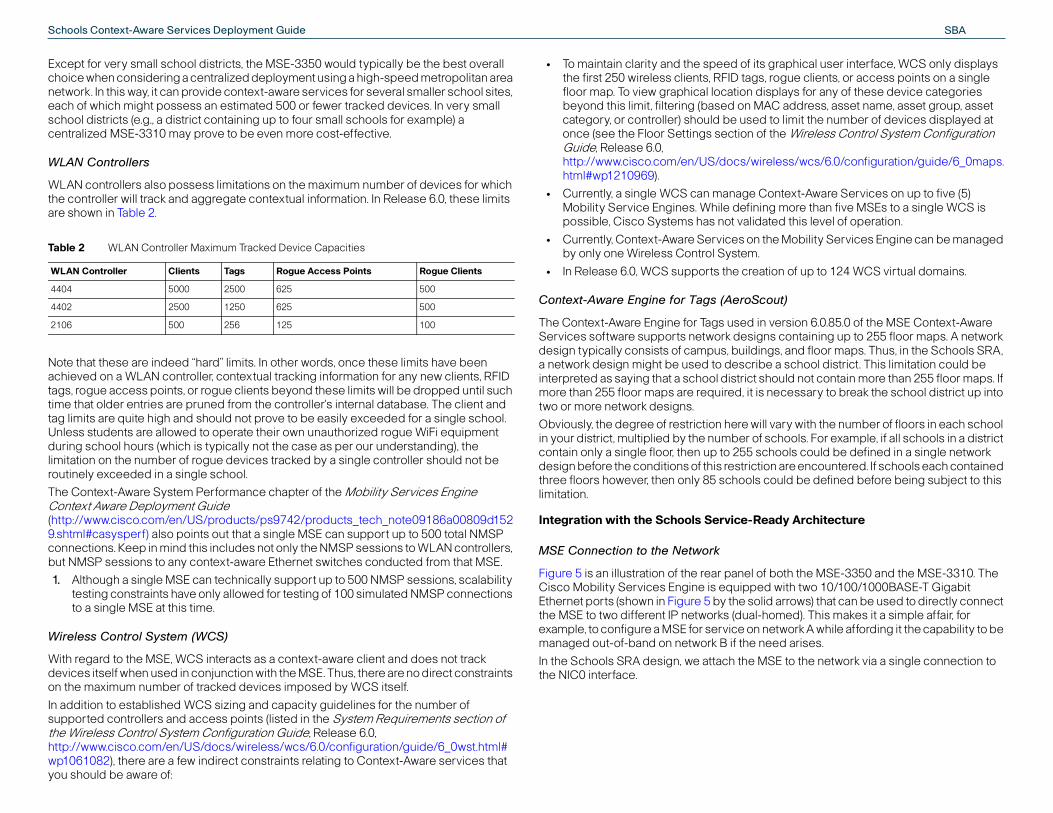
The building map shown in Figure 9 indicates that floor. Clicking directly on the building map takes usFigure 10. This is where we would actually see the ltags and rogues displayed. Wired devices that areswitches are not displayed on floor maps in Releas
SBASchools Context-Aware Services Deployment Guide
to WCS, you should create other users es assigned as necessary via the use ss Control System Configuration
6.0/configuration/guide/6_0manag.htrd to the proper procedure for S server. This chapter also contains a
S as well as the privileges contained in
ent of user privileges in the Schools y technical personnel should have d, you may wish to assign the ability to arger audience. This larger group can the “superuser” group. Most school tion available to them on WCS will not
rk activity in WCS. For these users, the nitoring or Monitor Lite user groups ecific WCS monitoring functions you
er-defined group shown in Figure 11 monitoring context-aware information, that the user is not allowed free rein to CS. For example, we may wish to allow unctions listed under the WCS “Maps” me school librarian probably has no
ce reports, thus we have not enabled count. Keep in mind that the
ay be different, so it may make sense losely fits your needs.
Figure 9 Building Level for School #1278
Figure 10 Floor Level for School #1278
Note Network designs are created in WCS, but they are not actually used for device tracking until they are transmitted to the MSE via a process known as network design synchronization. Only after network design synchronization has successfully occurred between WCS and its associated MSE will the network design actually be used by the Context-Aware Engine for Clients and the Context-Aware Engine for Tags. Synchronization of network designs and other components with the MSE is discussed in detail in the chapter entitled “Synchronizing Mobility Services Engines” in the Context-Aware Service Configuration Guide 6.0, http://www.cisco.com/en/US/docs/wireless/mse/3350/6.0/CAS/configuration/guide/msecg_ch3_CAS.html.
WCS Users, User Groups, and Virtual Domains
When installed, WCS provides for a single root user, which will have access to all WCS functions. The password for this root user should be protected and only known by those personnel at the district data center with a true need to know (e.g. those personnel responsible for the installation, maintenance, and detailed administration of WCS). Instead
of using the root user password for routine access and grant them administrative access with privilegof WCS user groups. Chapter 7 of the Cisco WireleGuide, Release 6.0 (http://www.cisco.com/en/US/docs/wireless/wcs/ml) provides comprehensive instructions with regaconfiguring users and group privileges on your WCcomplete listing of the user groups available in WCeach group.
Common sense should be applied in the assignmSRA. For example, while only a very small set of keaccess to the actual WCS root user ID and passwormake WCS configuration changes to a somewhat lbe assigned as WCS “admin” users or assigned tousers that are only interested in viewing the informaneed more than the ability to simply monitor netwoprivileges accorded them by the WCS System Momay be all that is required, depending upon the spwish to grant those users.
In our validation of the Schools SRA, the custom uswas found to be very useful in limiting users to onlyas well as some basic WCS alerts and events. Noteuse any of the monitoring functions provided by Wa librarian in a school to access the context-aware ffunction or search for a device by name. But this saneed to monitor school network security complianaccess to those reports for this librarian's WCS acrequirements of school users in your environment mfor you to develop a custom WCS user group that c

SBASchools Context-Aware Services Deployment Guide
ser's ability to even view certain ir active assigned virtual domain. For
gh school may have the ability to view s of wireless assets due to his WCS r group permitting this level of WCS
ment chairman director is assigned gainst these assets if they are located the physics department for school “A” location of RFID-tagged equipment in llow access to school B's resources.
sibilities, on the other hand, would be s in the district, including those in each ed to them by their user group against in assignment can be useful in prevent raffic whose nature might be based
er can take against a resource, hat resources those user group
use of virtual domains within WCS:
urces that we wish to include assigned and assigning network resources to ual Domains of the WCS Configuration
cs/6.0/configuration/guide/6_0virtua
er. The process for assigning a virtual ging WCS User Accounts
wcs/6.0/configuration/guide/6_0mana
on-root WCS virtual domain users the Services > Mobility Services main and device location. Refer to WCS Configuration Guide 6.0 ss/wcs/6.0/configuration/guide/6_0vif WCS functions that are not available
text-aware Ethernet switches are ntext Aware Service > Wired > Wired ual domain are able to display
effectiveness of WCS virtual e by the logged-in WCS user is 12, we can see from the left hand
e entire set of schools comprising the any of the WCS functionality accorded virtual domain setting might be
Figure 11 Custom User Group to Allow Context-Aware Monitoring
While WCS user groups define the WCS functionality users have been granted, WCS virtual domains allow the network administrator logically partition the WCS management domain and limit management access. In this way, the group of resources that the WCS functionality assigned to a user group may be exercised against is restricted. A WCS virtual domain consists of a set of assigned devices and maps, and restricts a user's scope to only information that is relevant to those devices and maps. Through a assigned virtual domain, users are only able to utilize WCS functionality against a pre-defined subset of the devices managed by WCS.
Users can be assigned one or more virtual domains, however only one assigned virtual domain may be active for a user at WCS login. The user can change the current virtual domain in use by selecting a different permitted virtual domain using the WCS Virtual Domain drop-down menu.
The WCS virtual domain can be used to limit the uresources inside WCS that are not contained in theexample, the Physics department chairman of a hithe location and other context-aware characteristicuser account being assigned to an appropriate usefunctionality. But the virtual domain that this departmay only allow such functionality to be exercised awithin his assigned school. Thus, if the chairman ofattempted to use WCS to discover the quantity andschool “B”, his assigned virtual domain would not a
Administrative personnel with district-wide responassigned a virtual domain that includes all resourceschool, and could exercise the functionality assignany of these resources. In this way, the virtual domaunnecessary inter-school WCS traffic, especially tmore upon curiosity rather than actual need.
Note WCS user groups assign what actions a uswhereas WCS virtual domains determine wactions can be applied towards.
There are two basic steps necessary to enable the
1. A virtual domain must be created, and the resoto the virtual domain. The process for creatingthe virtual domain is detailed in Chapter 20 VirtGuide 6.0 (http://www.cisco.com/en/US/docs/wireless/wl.html#wp1040002).
2. The virtual domain must be assigned to the usdomain to a user is detailed in Chapter 7 Mana(http://www.cisco.com/en/US/docs/wireless/g.html#wp1097733).
Note It is important to note that in Release 6.0, ncannot access WCS functions listed undermenu heading. This includes wired switchUnderstanding Virtual Domains as a User, (http://www.cisco.com/en/US/docs/wirelertual.html#wp1120787) for a complete list oin non-root virtual domains.
In Release 6.0, since wired devices attached to condisplayed using Services > Mobility Services > CoClients, only users that are assigned to the root virtcontext-aware information for these devices.
Figure 12, Figure 13, and Figure 14 demonstrate thedomains (note that the current virtual domain in ushighlighted in each figure by the red oval). In Figuremargin that the root virtual domain user can see thDowney School District, and is capable of applying to them by their WCS user group assignment. This

SBASchools Context-Aware Services Deployment Guide
atin Elementary)
en a user attempts to view information irtual domain. In this case, we see the
s resources in another school, #1278.
rs available that affect various NMSP nd its session partners. These rvices > System > NMSP Parameters, he selected MSE and any of its WLAN plete configuration information for ell as the default values for these ervices Engine Properties section of
3350/6.0/CAS/configuration/guide/m
nlikely that these parameters will rhaps in the very largest of schools vices, and a large quantity of wireless , in a centralized deployment, there is factors may cause delays that could e minimized by the appropriate in the network along with properly re adjustments to NMSP timing are eighbor dead interval, and response r of failed echo acknowledgments that ment.
ount of functional validation was contained in this document. However, ormance validation that could be ross a simulated Metropolitan Area y Services Engines in a centralized lly validated due to these time
appropriate, for example, in the case of a person requiring the ability to view and potentially take action upon all resources in the network. An example of a person in a school district that might require such capability could be a school district administrator.
Figure 12 Virtual Domain for Entire School District
In contrast, Figure 13 and Figure 14 each illustrate how the user's view of the school district in WCS can be severely curtailed when a WCS virtual domain is applied. A virtual domain setting such as this might be appropriate for most of the personnel within a school that might only need to work with school resources located in their school only. Figure 13 illustrates what a user in Warren High School #1278 would see if they were assigned a WCS virtual domain that limited their resource visibility to only those resources associated with Warren High School.
Figure 13 Virtual Domain Limited to School 1278 (Warren High School)
In Figure 14, we see the results of a WCS virtual domain for a user in Gallatin Elementary, School #1266. Note that a user that is assigned a virtual domain for school 1266 does not have visibility to any resources associated with other schools. All that is visible to the school 1266 user in this case are the buildings and floor maps associated with school 1266.
Figure 14 Virtual Domain Limited to School 1266 (Gall
Figure 15 illustrates the typical result that occurs whfor resources outside the scope of their assigned vresult of a user in school 1266 attempting to acces
Figure 15 Virtual Domain Permission Error
Mobility Services NMSP Parameters
WCS 6.0 provides us with several NMSP parameteprotocol timing characteristics between the MSE aparameters can be found at Services > Mobility Seand apply globally to all NMSP sessions between tcontroller or Ethernet switch session partners. Comconfiguring NMSP session timing parameters, as wparameters, can be found at Configuring Mobility Sthe Context-Aware Service Configuration Guide (http://www.cisco.com/en/US/docs/wireless/mse/secg_ch4_CAS.html#wp1014368).
When deploying an MSE locally in the school, it is urequire changes from the default values, except pewhere there might be several thousand tracked dedevices moving about on a regular basis. Howevermore of a chance that network congestion or othercause NMSP session timeouts. While this should bidentification and classification of NMSP data flowsdefined network QoS, there may be instances wherequired. In these cases, the NMSP echo interval, ntimeout values can be increased to limit the numbemay occur, especially in a centralized MSE deploy
Note Readers are advised that a tremendous amperformed in association with the content time constraints limited the degree of perfcompleted for Context-Aware Services acNetwork (MAN). The deployment of Mobilitfashion across a MAN was not able to be fuconstraints.

SBASchools Context-Aware Services Deployment Guide
well for us in our lab testing, we cannot ition that might occur in a production t you take the time to understand the lly the fact that they can be adjusted to promote improved NMSP session
n be found in the Configuring Mobility -Aware Service Configuration Guide 3350/6.0/CAS/configuration/guide/m
g
track up to a maximum of 18,000 are platform, and up to a maximum of
platform. The absolute limit on the termined by the hardware platform siding on the MSE, and the level of s configuration panel (located at vice > Administration> Tracking ine just how much of the MSE's
ted towards the tracking of specific A environment in order to allow the e access points and rogue clients, but d introduction of rogues is not allowed king capacity on the MSE.
onfiguration to:
and wireless client stations, asset tags,
apacity will be allocated to certain an example of how this can be ked clients and rogue clients/APs are d on the number of RFID tags tracked, er of tags tracked will be allowed to 0 tags).
ed from tracking due to the he “Not Tracked” device count column
To aid in determining whether echo packets are being dropped, you can use the WCS function Services > Mobility Services > System > Status > NMSP Connection Status as shown in Figure 16. This WCS menu panel displays all the NMSP session partners for this MSE, along with echo request and response counts. For example, in the figure for the Mobility Services Engine with the hostname MSE1, we see that there are currently two NMSP sessions to two different school WLAN controllers.
Figure 16 NMSP Connection Status
We can see in Figure 16 that both of the NMSP WLAN controller sessions appear to be functioning properly, as the number of Echo Requests issued is seen to be exactly equal to the number of Echo Responses received. This might not always be the case and small static differences over a long period of time do not necessarily indicate a serious problem. However, sluggish performance combined with a regularly increasing discrepancy in the delta between the number of requests issued and responses received could be indicative of the NMSP session timing out. In a centralized deployment, this may be due to unforeseen levels of congestion or other resource constraint. In this case, raising the response timeout may assist in alleviate the timeouts. Keep in mind, however, that a successful centralized deployment assumes that there is sufficient MAN capacity available to each school and that QoS has been applied appropriately.
Figure 17 gives an example of the NMSP Parameter screen that is located at Services > Mobility Services > System > NMSP Parameters, which we can use to change the system defaults. In Figure 17, the network administrator or network technician has instituted the following changes from the defaults: the echo interval has been raised to 30 seconds, the neighbor dead interval has been raised to 60 seconds, and the response timeout has been raised to 5 seconds.
Figure 17 Example of NMSP Parameter Modification
Note Although the NMSP configuration worked predict and simulate each and every conddeployment. Therefore, it is important thafunction of these parameters and especiabeyond the values illustrated here in orderstability and network performance.
Further information on these NMSP parameters caServices Engine Properties section of the Context(http://www.cisco.com/en/US/docs/wireless/mse/secg_ch4_CAS.html#wp1014368).
Context-Aware Service Parameters—Trackin
As mentioned earlier, Context-Aware Services canlicensed devices when using the MSE-3350 hardw2,000 licensed devices when using the MSE-3310number of clients or tags that can be tracked is deused, the presence of any other applications co-relicensing purchased. The WCS tracking parameterServices > Mobility Services > Context Aware SerParameters) allows the administrator to pre-determmaximum licensed tracking capacity will be allocadevice categories. This is useful in the Schools SRtracking of device categories such as nearby rogualso limit these categories such that an uncontrolleto consume all of the remaining context-aware trac
We can use the Context-Aware Service Tracking c
• Entirely enable or disable the tracking of wired rogue access points, and rogue clients.
• Set limits on how much MSE tracked device cdevice categories. Figure 18 provides us with achieved, where the maximum number of traccapped at 4,000 devices each. No limit is placewhich in effect means that the maximum numbrise until the tag licensing limit is reached (3,00
Note that any devices that are detected but excludenforcement of a tracking limit will be reflected in tshown on the right side of the display.

SBASchools Context-Aware Services Deployment Guide
er of items for which you are tracking decrease the number of days of
ld be done with careful consideration, amount of space consumed by the
hich Context-Aware Services on the ed devices may wish to consult with co Technical Assistance Center
en recalling the history for a tracked AN client. As shown in Figure 20, the
rded for the client. Setting the “change licking play displays the various client
the image (this can be enlarged for gh all of the stored locations for the formation could be very useful to gineers, as well as school resource y be looking for information useful in
e place in the past.
t in the School
n making adjustments to history ts:
oducts_tech_note09186a00809d152
3350/6.0/CAS/configuration/guide/m
for tags, WLAN clients, and rogues that programs that are monitoring specific le both conditional notifications and
the mobility services engine sends to short, relatively simple messages via slog, or as an SNMP trap. Conditional s, or rogue devices. The conditions
Figure 18 Context-Aware Service Tracking Parameters
Note In Release 6.0, wired client tracking can be enabled or disabled, but imposing a limit solely on the number of wired clients tracked is not supported at this time. As a workaround, use switch CLI commands such as the global nmsp disable or the interface nmsp suppress attachment commands to limit the number of tracked wired clients that are presented to the MSE.
Context-Aware Service Parameters—History
The MSE records and maintains historical location and statistics information for wireless clients, tags, rogue access points, and rogue clients. This information is available for viewing through WCS or via third-party context-aware application clients, and can be very valuable in helping establish patterns of movement for tracked assets and rogues. Historical information can be used for location trending, asset loss investigation, RF capacity management, and facilitation of network problem resolution. Contextual information such as whether an emergency button was depressed or whether an asset tag has moved into close proximity to a chokepoint trigger is also tracked in the history data.
The collection of historical information must be explicitly enabled for each desired category of device (as shown in Figure 19). By default, 30 days of historical data are stored in the MSE.
Figure 19 MSE History Parameters
There are several variables that can affect how much historical information can be stored by the MSE for the tracked assets in your school or school district. Among these variables are the average number of elements that move, average distance covered every time there is a movement, information transitions, telemetry information from tags, and so on.
Depending on these variables as well as the numbhistory information in your school, you may wish tohistorical data to a value below 30 days.
Changes to the default history archive period shousince longer history periods typically increase thehistory database. Users unfamiliar with the way in wCisco MSE archives historical information for trackyour Cisco field technical representative or the Cis
Figure 20 illustrates what you can expect to see whdevice. Here, we recall the history for a specific WLfocus of the display is the list of past locations recoselection time” parameter on the screen and then clocations on the small floor map at the right side ofeasier viewing). In this way, you can step back throuclient within the history database. Obviously, this inschool administrators, district and school WLAN enofficers and other law enforcement officials that marecreating a sequence of events that may have tak
Figure 20 Display of Location History for a WLAN Clien
Further information on the procedure to follow wheparameters can be found in the following documen
Context Aware Solution Deployment Guide http://www.cisco.com/en/US/products/ps9742/pr9.shtml#rfid
Context Aware Service Configuration Guide 6.0 http://www.cisco.com/en/US/docs/wireless/mse/secg_ch7_CAS.html#wp1128896
Context Aware Service Parameters—Notifications
Cisco WCS allows you to define certain conditions cause the MSE to send notifications to application ports. You can use Cisco WCS to define and enabnorthbound notifications.
Conditional notifications are those notifications thatCisco WCS and other applications that can receiveSOAP/XML (either HTTP or HTTPS), SMTP, UDP Synotifications can be triggered by WLAN clients, tagavailable include:

SBASchools Context-Aware Services Deployment Guide
eters
only when you can reasonably expect arge number of notifications or when it ped.
ns only.) This is the rate in milliseconds ations. A value of 0 (default) means that
notifications as fast as possible. If you to communicate to a third-party r example) in the Schools SRA, it is tifications are expected to be
ll be requested of the MSE per minute. such as an emergency notification) is ely unusual to see a great deal of
ols at the same time. However, a more ent that would be used in a parent d to generate much more traffic
when a large number of parents might an school district. In cases such as this a normal and routine event, it is
to allow the MSE to pace the e limit value of 200 would slow the rate 200 msec). The correct notification t depending on the amount of traffic
notification queue of the MSE. Default nd for the MSE-3310 it is 5,000. The his limit if the output notification queue you are using context-aware he Queue Limit parameter in unter to avoid any notifications from ons Dropped counter is greater than
e Limit parameter to avoid any future es for this parameter however, it is t in rare cases where very many
e retry count specifies the number of the refresh timer expires. The default ns transmitted between Refresh Time for Retry Count. After the value of one ation appliance skips firing any further device for the time period specified
s expired, this cycle repeats unless the d to help ensure (to a limited extent)
• Missing—The MSE generates a Missing Asset conditional notification if it has not located the asset for more than a specified number of minutes.
• In/Out—The MSE generates an In/Out conditional notification if the asset is found to be inside of, or outside of, a selected area.
• Distance From Marker—The MSE generates a Distance From Marker conditional notification if the asset is found to be beyond a specified distance from a designated marker.
• Battery Level—The MSE generates a Battery Level conditional notification if the battery level reported by an asset tag is equal to a selected value.
• Location Change—The MSE generates a Location Change conditional notification if the asset experiences a change in location.
• Emergency—The MSE generates an Emergency conditional notification if a tag button, tamper or detached event is detected.
• Chokepoint—The MSE generates a Chokepoint Conditional notification if a tag enters into the proximity of a chokepoint trigger.
Northbound notifications are a special category of notification that is specific to RFID tags only. They define which tag notifications the MSE will send to third-party applications using SOAP/XML. Northbound notifications can include chokepoint, telemetry, emergency, battery, and tag vendor data. Optionally, the tag's location coordinates can be included within the northbound notifications as well. An important difference between conditional notifications and northbound notifications is that northbound notifications can contain considerably more information. The information sent in the northbound notification is sent in a pre-defined data format. Details regarding the data format for northbound notifications are available on the Cisco developers support portal at http://developer.cisco.com/web/contextaware.
Note In Release 6.0, neither conditional nor northbound notifications can be applied to tracked wired devices.
Complete and detailed information regarding how to configure Context-Aware Notifications can be found in the following locations:
• Configuring Event Notifications chapter of the Context-Aware Configuration Guide 6.0 (http://www.cisco.com/en/US/docs/wireless/mse/3350/6.0/CAS/configuration/guide/msecg_ch6_CAS.html).
• Enabling Notifications and Configuring Notification Parameters section of the Context-Aware Configuration Guide 6.0 (http://www.cisco.com/en/US/docs/wireless/mse/3350/6.0/CAS/configuration/guide/msecg_ch7_CAS.html#wp1129909).
• Context-Aware System Performance section of the Context-Aware Solution Deployment Guide (http://www.cisco.com/en/US/products/ps9742/products_tech_note09186a00809d1529.shtml#casysperf).
Via the menu panel located at Services > Mobility Services > Context Aware Service > Advanced> Notification Parameters (Figure 21),WCS allows the user to modify several advanced timing parameters pertaining to conditional notifications and northbound notifications. For example, you can limit the rate at which the MSE generates notifications, set a maximum queue size for notifications, and set a retry limit for notifications with in a certain period.
Figure 21 Context Aware Advanced Notification Param
Note Modify advanced notification parameters the Mobility Services Engine to transmit a lis noticed that notifications are being drop
• Rate Limit—(Pertains to northbound notificatioat which the MSE generates northbound notificthe Mobility Services Engine generates eventare using the northbound notifications systemapplication (such as AeroScout MobileView, forecommended that you consider how often nogenerated and how many total notifications wiFor example, an exception based notification (not a normal event and thus it would be extrememergency events generated from many schoroutine event, such as the chokepoint entry evcurbside pickup application, could be expecteduring, for example, the hours of 2:00-2:30 PM,be expected to pick up children from a suburbwhere a large number of notifications might berecommended to increase the rate limit so as transmission of notifications (for example, a ratof notification transmission down to one everydelay will vary from deployment to deploymengenerated.
• Queue Limit—Specifies the size of the outputqueue limit value for the MSE-3350 is 18000 aMSE drops any outbound notifications above tsize is exceeded. In the School SRA design, ifnotifications, it is recommended that you use tconjunction with the Notifications Dropped cobeing dropped. If you notice that the Notificatizero, you should consider increasing the Queuincreases. Given the relatively large default sizunlikely that adjustment will be required excepnotifications are generated.
• Retry Count—For each matching condition, thtimes to generate an event notification before value is 1. The total number of event notificatioperiods is equal to one plus the value specifiedplus the Retry Count has been reached, the locnorthbound notifications for this condition andby the Refresh Time. Once the Refresh Time haevent has been cleared. Retry count is intende

SBASchools Context-Aware Services Deployment Guide
o Context-Aware Services can be art of our school network (such as
ops, wireless desktops, etc.). Generally vice has its 802.11 wireless network dic transmissions (probe requests), text-Aware Services. Since devices owered on for the entire day and se devices become useful in helping
h the device is assigned. As the device d that the chances of the device being thus its usefulness as a way to ell.
ork interface adapter works well if the n operation and use this information to k, or its interaction with an application. ool environment to perform one or
of how this functionality can be put to
ortable devices may congregate, be further optimized to enhance
located within the school or district ipment is “borrowed” from one l to another) without permission.
n to be visiting guests, and helping ve been explained to be off-limits to
to establish a pattern of usage and any past actions that might relate to
arameter for network troubleshooting
utput devices) as input to an e is available and most convenient for er's location.
vices can be used with Cisco WCS to ers equipped with Cisco 7925G IP
nvironment. Note that we have chosen th each device, rather than the device ient icons shown in Figure 22 displays luding its client properties, association well as its event history.
that notifications reach their intended destination. If notifications are not indicated as being dropped by the Notifications Dropped counter, but are not reliably reaching their destination application, you may wish to increase the number of notifications sent between Refresh Time periods by raising the Retry Count judiciously.
• The Mobility Service Engine transmits notifications using a “Fire and Forget” technique. Notifications are not retained in any database within the MSE after they are transmitted.
• Refresh Time—The wait time in minutes that must pass before an event notification is resent. The default is 60 minutes. Refresh Time and Retry Count are used cooperatively to help limit the number of notifications repeatedly generated for events that have not been cleared. Retry Count limits the number of notifications that are sent by the MSE, while Refresh Time imposes a “waiting period” during which time no further notifications are sent for this event condition and device. If you are noticing that repeated notifications are being generated for the same event, it may be due to the condition not clearing within the refresh time interval. In this case, you may wish to investigate why the triggered condition does not clear and possibly extend the refresh time.
• Notifications Dropped—The number of event notifications dropped from the queue since startup. The Notifications Dropped counter should be used in conjunction with the Queue Limit parameter to reduce the number of total dropped notifications.
WLAN Controller and Ethernet Switch Definition and Synchronization
To allow for proper tracking of the devices that may be registered or attached to them, WLAN controllers and context-aware Ethernet switches must be defined to WCS and then synchronized with the Mobility Services Engine.
Detailed information regarding how to add WLAN controller definitions to WCS using the WCS Configure > Controllers menu panel can be found in the section entitled Adding Controllers in the WCS Configuration Guide 6.0 (http://www.cisco.com/en/US/docs/wireless/wcs/6.0/configuration/guide/6_0ctrlcfg.html#wp1041451).
Detailed information regarding how to add Ethernet switch definitions to WCS using the WCS Configure > Add Ethernet Switches menu panel can be found in the WCS Configuration Guide 6.0 (http://www.cisco.com/en/US/docs/wireless/wcs/6.0/configuration/guide/6_0ctrlcfg.html#wp1089752).
Detailed information regarding how to synchronize the MSE with WLAN controllers and context-aware Ethernet switches using the WCS Services >Mobility Services > Synchronize WCS and MSE(s) menu panel can be found in the Synchronizing Mobility Services Engines chapter of the Context-Aware Service Configuration Guide 6.0 (http://www.cisco.com/en/US/docs/wireless/mse/3350/6.0/CAS/configuration/guide/msecg_ch3_CAS.html#wp998995).
Note Always ensure that the MSE is synchronized with the primary WLAN controllers it is providing Context-Aware Services for, as well as any backup WLAN controllers in the Schools SRA design. If the MSE is not kept in synchronization with your backup WLAN controllers, Context-Aware Services may not function properly or may not be available at all for WLAN clients and RFID tags in the event of a primary WLAN controller failure.
Wireless Client Context-Aware Considerations
The ability to track WLAN client location using Ciscuseful in a school to locate WLAN clients that are pauthorized 7921G and 7925 VoWLAN phones, laptspeaking, provided that a 802.11 wireless client deinterface adapter powered on and is sending periothese WLAN client devices can be located by Consuch as portable VoWLAN phones are very often pcarried on the belt, purse, or pocket of the user, thelocate not only the device itself but the user to whicbecomes larger in size and heavier in weight, we finwith the assigned user all the time diminishes and determine the location of the user diminishes as w
Tracking WLAN client devices by their wireless netwgoal is to track the location of the device when it is ienhance the operation of the device on the networFor example, using WLAN client tracking in the schmore of the following represents a prime example use in the school environment:
• Determining where wireless users and their pallowing for the placement of access points tooverall coverage and performance.
• Investigate where a missing device is currentlycampus. A good example might be when equclassroom to another (or even from one schoo
• Determining the location of users that are knowensure that they do not stray into areas that hathem.
• Using the location history of a wireless devicelocation in order to clarify past actions, such assafety and security concerns.
• Use the location of wireless LAN clients as a pand security audits.
• Use the location of wireless printers (or other oapplication designed to determine which devica particular wireless user depending on the us
Figure 22 illustrates how Cisco Context-Aware Serdisplay the current location of school faculty membphones, laptops, and PDAs in a sample lab school eto assign and display the user name associated wiMAC address. Clicking on any of the blue WLAN cla plethora of information about the client device, inchistory, connection troubleshooting information, as

SBASchools Context-Aware Services Deployment Guide
nvolved with important procedures r WLAN Clients, or the definition of deployment procedures. For ould be understood prior to ce Deployment Guide roducts_tech_note09186a00809d152
ant Context-Aware Considerations
ess WiFi Link 4965AGN, Intel® he Intel® PRO/Wireless 2915ABG that the default “Personal Security” oes not include compatibility with the r to enable compatibility with the
el ProSet client supplicant must be rity” and to enable Cisco Compatible d Figure 24).
tel® ProSet Clients
Figure 22 WLAN Client Tracking
If the intention is to try and track a wireless device for inventory or loss prevention purposes, it is important to ascertain whether the embedded network interface remains active for any devices that may be in a powered-down or standby state. Even so, if the device remains active but accesses the network only very infrequently in order to conserve power, the degree of location fidelity obtained will likely be less than optimal, especially if the device can be expected to move frequently while in this state. A higher accuracy solution for this type of full-time location tracking application would be to attach or embed a RFID asset tag (see RFID Asset Tag Context-Aware Considerations) to the device. RFID tags are independently powered and operate without concern for the power state of the WLAN client device, and can be stimulated to transmit immediately when passing in proximity of properly equipped doorways and exits.
In general, best results are obtained in context-aware designs when all WLAN clients are compliant with the Cisco Compatible Extensions for WLAN Clients specification v2 at minimum, and preferably with the Cisco Compatible Extensions for WLAN Clients specification v4 or v51.
Additional information on the Cisco Compatible Extensions program for Wi-Fi Client Devices is available at http://www.cisco.com/web/partners/pr46/pr147/partners_pgm_concept_home.html.
Note that this document does not detail the steps isuch as calibration of the Context-Aware Engine folocation inclusion and exclusion regions and otherinformation on these and other procedures that shdeployment, refer to the MSE Context Aware Servi(http://www.cisco.com/en/US/products/ps9742/p9.shtml).
Intel® Wi-Fi Clients and ProSet Client Supplic
When using clients equipped with the Intel® WirelPRO/Wireless 3945ABG Network Connection, or tNetwork Connection adapter, it is important to notesettings of the Intel® ProSet Configuration Utility dCisco Compatible Extensions specification. In ordeCisco Compatible Extensions specification, the Intused to reconfigure the client for “Enterprise SecuExtensions using the “Cisco Options” (Figure 23 an
Figure 23 Enabling Cisco Compatible Extensions on In
1. Readers interested in the technical details concerning compatibility with the Cisco Compatible Extensions for WLAN Clients specification v2 are referred to the section entitled Tracking Clients, Assets and Rogue Devices in Wi-Fi Location Based Services Design Guide 4.1, http://www.cisco.com/en/US/docs/solutions/Enterprise/Mobility/wifich3.html#wp1049277

SBASchools Context-Aware Services Deployment Guide
nications Manager
ode be used only in situations where nessed. This is because a trade-off ncy of probe requests transmitted is battery life. If you do not notice the ommended that you leave the CUCM
tential safety and security applications erprise sectors, from the logistics arehouse, to the motorist with the
search for change at the toll booth, ress a wide realm of challenges.
gs and Cisco Context-Aware Services
Figure 24 Enabling Cisco Compatible Extensions on Intel® ProSet Clients (2)
Cisco 7921 and 7925G Context-Aware Considerations
7921G and 7925G Unified IP Wireless Phone users should note that phones that are idle and not currently participating in an active call may not transmit 802.11 Probe Requests with sufficient frequency to ensure that changes in the actual location of the phone user are promptly reflected in the calculated location coordinates provided to the contest-aware services software in the MSE. In some cases this can be of concern, especially if the 7921G or 7925G user remains within the primary coverage area of the same access point for long periods of time. In cases where an access point might have a large coverage footprint, a roaming event may not occur very often despite a significant change in user location.
If you experience situations where the location fidelity of a 7921G or 7925G Unified IP Wireless Phone appears to be much better for those users actively participating on a call versus those that are on hook and idle, you may wish to consider changing the scan mode parameter associated with the 7921G or 7925G device in the Cisco Unified Communications Manager. In some cases, improved location fidelity can be achieved by enabling the “continuous” scan mode on the Device=>Phone configuration page of Cisco Unified Communications Manager Administration (shown in Figure 25). Note that scan mode options listed are “auto”, “continuous”, and “single AP”, where auto is the default. “Continuous” scan mode causes the wireless IP phone to issue a probe request approximately every two seconds, whereas “auto” scan mode causes the device to issue probe requests primarily only when the device is engaged on an active call, when roaming, or when preparing to roam. “Single AP” is used in installations where the wireless IP phone is only used in the vicinity of a single access point at all times, as probe requests are issued only when the wireless IP phone is first powered on. “Single AP” mode is not applicable and should not be used in the Schools SRA design.
Figure 25 Scan Mode Option in Cisco Unified Commu
Note It is recommended that continuous scan mthe anomaly described here is actually witassociated with any increase in the frequethe potential for reduced 7921G or 7925Ganomaly described in this section, it is recscan mode setting at the “auto” default.
RFID Asset Tag Context-Aware Considerations
Radio Frequency Identification (RFID) has many poin the education arena. Already used in various entdepot that tracks pallets of goods throughout the w“EZ-Pass” or “CruiseCard” that no longer needs to schools can now embrace RFID technology to add
Figure 26 Floor Map Showing Various Uses of RFID Ta

SBASchools Context-Aware Services Deployment Guide
ol
plication in a suburban school system ol faculty assistants when a parent has child at the end of the school day. By and known to the context-aware
ased. School personnel are aware that rty and is waiting in the queue for their reas and classrooms in an efficient ueue at the school front entrance. This ure 28), gets parents and students in s the amount of pollutants emitted by up and drop off.
corded and registered with a particular parent and vehicle is e arrival of a young student’s mother
ce of an RFID tag assigned this label at at the school driveway entrance. Even 6 provides a conceptual illustration of rate a SOAP/XML notification to a Wisnewski”). The receiving application le notification in the school that this
ould be brought forward and queued am of cars enters the school driveway
nnel are made aware that the parent is at the curbside front door pickup area age this process and drastically
s to dispatch those children to those r children each day.
ssets, Cisco Context-Aware Services sset and its environment available to ML API. For instance, if the asset tags
we can also read the current MSE. This can be seen in Figure 29, perature surrounding our HVAC ble 68 degree Fahrenheit. Looks like
job from what this tag sensor tells us. It
The illustration in Figure 26 provides us with a visual representation of just some of the ways RFID can be used in the Schools SRA in conjunction with Context-Aware Services:
• High value assets (such as projectors, microscopes, telescopes, audio/video equipment, etc.) can be kept safe and secure, since the application of RFID tags to these assets provides school administrators and school resource officers with the ability to locate the assets quickly and efficiently. Figure 26 illustrates how the present location of assets equipped in this fashion can be quickly ascertained by a quick check of the school floor map. Here we can see the last known location of a lab centrifuge, microscope, telescope, portable PA system, XVGA projector, and even a mass spectrometer. For buildings containing more than a single floor, database search techniques can be used to search for the desired asset by name or attached RFID tag MAC address.
Figure 27 ID Badge with Embedded Active RFID
• Faculty and administrators can wear specially manufactured badges (see Figure 27) that combine a traditional identification card with active RFID technology, allowing them to be located quickly in the event of an emergency. These same devices can also transmit special notifications using a push button sequence, which can be interpreted in various ways by Context-Aware Services, including as a signal that an emergency event is in progress. Figure 26 illustrates how a person can be located if they are carrying an RFID-enabled ID card, as seen in the displayed location of the school’s resource officer (a law enforcement official), whose location is currently indicated as being inside of the school principal’s office. Being able to physically locate the school resource officer using a tool such as this could help in saving precious seconds in the event of a school emergency.
• The whereabouts of school visitors (such as maintenance or repair contractors) can be monitored and alerts triggered to school resource officers and others if these visitors stray into areas that they have no authorization to be in. For example, in Figure 26, we see that in our school we have an HVAC repair contractor as well as a visiting parent. In addition to making us aware as to the presence of these visitors, our system can alert us if these personnel access areas that we do not want them to by comparing their current locations to location boundaries we have defined as notification rules. Third-party applications that can access context-aware information from the MSE may perform more advanced tasks as well.
• RFID tag technology can be combined with chokepoint triggers (Exciters) to enable the use of proximity applications. In this fashion, chokepoint triggers can serve many purposes, including stimulating asset tags affixed to assets that might be in the process of being removed from the school building without authorization. This makes it possible to notify school officials or resource officers of such action, so as to act quickly and determine whether such movement is legitimate.
Figure 28 Curbside Congestion at an Urban K-12 Scho
• The concept of a curbside student receiving apthat notifies student hallway monitors and schoentered school property, ready to pickup theirissuing the parent an RFID tag that is serializedsystem, safety, security, and efficiency is increthe parent's vehicle has entered school propechild. Children can be retrieved from waiting amanner, and presented to parents that are in qreduces school curbside congestion (see Figand out of the school area quickly, and reduceidling vehicles waiting in line for curbside pick
An RFID tag whose MAC address has been reContext-Aware Services as to being issued toshown in Figure 26. In Figure 26, we see that th(“Mrs. Wisnewski”) is signified by the appearanthe location of the chokepoint trigger installedmore importantly, the lower portion of Figure 2how Cisco Context-Aware Services can genereceiving application (“Parent Pickup: Johnny then could be used to trigger visual and audibchild’s parent has arrived and that the child shfor release. As each parent vehicle in a long streand takes its place in the queue, school persoonly a few hundred yards away and will soon beto pickup their child. This system can help manincrease the ability of limited school resourceparents that prefer to drop off and pick up thei
In addition to simply displaying the location of amakes other contextual characteristics of the aapplications accessing the MSE via its SOAP/Xused contain on-board temperature sensors, temperature surrounding the asset tag via thewhere we see from WCS that the ambient temrepairman is 20 degrees Celsius or a comfortaour school air conditioning system is doing its

SBASchools Context-Aware Services Deployment Guide
d that tags be configured for the nels, which is typically channels 1, 6, national regulatory domain).
ime between periodic tag en the tag is stationary and not in
red for values between 3 and 5
tags with motion sensors.) This is the rated when the tag and asset is in
onds.
popular RFID tags default to d channels. Tag parameters that
s specify the number of times each l. It is generally recommended that this
helps protect against lost tag e, which is a primary cause of poor tag
subsequent message repetitions on ec, although in lab testing we have y when a message repetition interval e of 2 seconds for NMSP notification
the section entitled RFID Tag and WLC are Deployment Guide
roducts_tech_note09186a00809d152
procedures such as calibration of the ent procedures. For information on tood prior to deployment, refer to the
roducts_tech_note09186a00809d152 Engine for Tags for the Cisco MSE
cout representative or nded.
devices that trigger RFID asset tags to ange (otherwise known as the avioral modification may, for example, ue identifier (MAC address) or cause ing on how the tag is programmed. A
ulate the asset tag such that it provides ited a given area, known as a
at provide passage between ances and exits such as doorways,
oScout Ltd., and represent a popular
is important to note that while WCS is used to view this information in Figure 29, any authorized context-aware application that is written to use the MSE SOAP/XML API could have accessed this data as well.
Figure 29 Temperature Telemetry Information
Simply put, RFID technology and Cisco Context Aware Services can help schools improve their overall safety, security, and efficiency.
Cisco Context-Aware Software is designed to function with active RFID asset tags from vendors compliant with the Cisco Compatible Extensions for Wi-Fi Tags specification. A list of current Cisco Compatible Extensions for Wi-Fi Tags compliant vendors can be found at http://www.cisco.com/web/partners/pr46/pr147/ccx_wifi_tags.html. Although all vendor RFID tags compliant with the Cisco Compatible Extensions for Wi-Fi Tags specification share a great deal of functionality in common, the parameter names and means used to configure each brand of tags can differ from vendor to vendor, therefore no set prescribed configuration parameter list would apply to all. That being said, there are several general configuration functions that tag vendors share and although the exact parameter names may differ, it is important that you understand them and use this knowledge accordingly when configuring the particular tags of choice for your installation. More information regarding the configuration procedure for AeroScout tags can be found in the section entitled RFID Tag and WLC Configuration/Tuning in the Cisco MSE Context-Aware Deployment Guide (http://www.cisco.com/en/US/products/ps9742/products_tech_note09186a00809d1529.shtml#rfid-wlc)1.
• RF Channel Configuration—It is recommendestandard set of 2.4 Ghz non-overlapping chanand 11 (this may vary depending on your inter
• Stationary Transmission Interval—This is the ttransmissions that are normally generated whmotion. It is recommended that this be configuminutes.
• Motion Transmission Interval—(Applies only totime between periodic tag transmissions genemotion. A recommended initial value is 15 sec
• Number of Tag Message Repetitions—Some transmitting a single transmission on all definecontrol the number of tag message repetitiontransmitted message is repeated, per channeparameter be set to a value of three. Doing thistransmissions due to congestion or interferenclocation accuracy.
Message Repetitions Interval—The delay betweenthe same channel. This is often defaulted to 512msseen some evidence of improved location accuracof 256 msec is used with the default controller valuinterval. This parameter is discussed in more detailConfiguration/Tuning of the Cisco MSE Context-Aw(http://www.cisco.com/en/US/products/ps9742/p9.shtml#rfid-wlc).
This chapter does not detail the steps involved withContext-Aware Engine for Tags and other deploymthese and other procedures that should be undersMSE Context Aware Service Deployment Guide (http://www.cisco.com/en/US/products/ps9742/p9.shtml). In addition, the AeroScout Context-AwareUsers Guide, version 3.2, available from your AeroShttps://support.aeroscout.com, is highly recomme
RFID Tag Chokepoint Trigger Considerations
Chokepoint triggers are proximity communication alter their behavior when the tag enters into close rstimulation zone) of the chokepoint trigger. This behcause the RFID tag to immediately transmit its uniqthe tag to change its internal configuration, dependvery popular use of the chokepoint trigger is to stimindication to the MSE that the tag has entered or exchokepoint. Chokepoints are entry or exit points thconnected regions. Common chokepoints are entrhallways, and stairwells.
Note An Exciter is a registered trademark of Aerexample of a chokepoint trigger.
1. Additional information can also be found in the Wi-Fi Location-Based Services Design Guide 4.1 section entitled Configuring Asset Tags, located at http://www.cisco.com/en/US/docs/solutions/Enterprise/Mobility/wifich6.html#wp1077248.

SBASchools Context-Aware Services Deployment Guide
is innocently installed by a school user ork, the unauthorized and potentially
can unnecessarily expose our secure
cation capabilities provided by the text-Aware Engine for Clients to define wireless clients that may be using
igure, we can see icons for both rogue er their predicted positions on a floor
hool district. This capability is very ll as the district network administrator ine the location of wireless equipment ed in an attempt to gain unauthorized
In Figure 30, the round icon with the ccess point and the rectangular icon associated to this rogue access point.
ocation of Rogue Access Points and Clients
ags, it is normal to experience a ccess points and rogue clients. The
that these devices are not under the , the configuration of such these rogue aware location accuracy (for example, ions devices, etc.).
In schools, chokepoint triggers are useful in causing RFID tags to react quickly when assets are moved past certain points in the school. This could be a microscope with an affixed RFID tag moving past a chokepoint trigger located near a school exit, a faculty member with an RFID badge walking into the school through the front entrance at 7:00 AM, or it could be a parent in the family automobile that has a RFID tag on the front visor coming past a chokepoint trigger located at the entrance of the school property. In all these cases, the chokepoint trigger causes the tag to change its behavior, most likely to immediately transmit its MAC address (as well as the MAC address of the chokepoint trigger that stimulated it) to the MSE via one or more access points that can receive the tag's transmissions. The net result is to cause the MSE to indicate that the current location of the asset and its asset tag is within a known, pre-determined proximity of the chokepoint trigger.
In order to use chokepoint triggers with Cisco Context-Aware Services, they must be properly configured using the appropriate vendor-supplied software utility, defined to WCS, placed on floor maps, and synchronized as part of an updated network design to the MSE. After all of this is complete, the MSE is able to recognize the transmissions generated by asset tags that have been stimulated by specific chokepoint trigger MAC addresses. Based on this information, the MSE can attempt to localize the tag to the proximity of the chokepoint trigger. Applications such as WCS (or third party context-aware applications) may then display the asset tag's location at the chokepoint icon associated with the chokepoint trigger's MAC address.
Various chokepoint trigger specific parameters such as transmission range, IP address, transmission interval, transmission repetitions, and so on are set using vendor-specific utilities. Note that each vendor maintains their set of software tools necessary for configuration of their chokepoint triggers. These software configuration tools are not interoperable between vendors (for example, AeroScout software configuration tools cannot be used to configure WhereNet chokepoint triggers or vice-versa).
The individual configuration of each vendor's chokepoint trigger is beyond the scope of this document. Complete and detailed configuration information relating to the specific configuration of each vendor's chokepoint trigger can be found in the appropriate vendor's documentation, which can be obtained from your tag vendor representative.
• AeroScout EX-3200 User Guide https://support.aeroscout.com
• AeroScout Exciter EX-2000 User Guide https://support.aeroscout.com
• AeroScout Context-Aware Engine for Tags for the Cisco MSE Users Guide, version 3.2 https://support.aeroscout.com
Technical documentation for WhereNet WherePort chokepoint triggers and the necessary software and hardware for configuration of WherePorts is available from WhereNet Corporation (http://www.wherenet.com) or via your WhereNet account representative.
Rogue Device Context-Aware Considerations
The use of context-aware services for locating clients and RFID tags that we have defined and authorized in the school environment is often what first comes to mind for many of us when we consider this solution. However, another equally important and useful function of context aware services is the ability to detect the location associated with those wireless clients and access points that we have not authorized to operate within our domain. In other words, context-aware services in our schools can help us in locating rogue access points or rogue clients that may have been installed within our school by students, contractors, visitors, vendors, or even faculty or administration members without
authorization. Even if an unauthorized access pointthat is otherwise authorized to use the school netwinsecure portal provided by such an access point school network to outside intruders.
The Cisco Wireless Control System can use the loCisco Mobility Services Engine and the Cisco Conthe location of unauthorized access points and thethese access points, as shown in Figure 30. In the faccess points as well as rogue clients displayed ovmap of an elementary school located within our scuseful both to the local school administrator, as weand their technical teams. It allows them to determthat may have been brought into the school and usaccess to school or district computing resources. “skull and crossbones” logo represents the rogue awith the same logo represents a rogue client that is
Figure 30 Using Context-Aware Services to Perform L
Note In comparison to WLAN clients and RFID treduced accuracy when localizing rogue avery nature of “rogue” devices establishescontrol of school administration. Thereforedevices may not facilitate optimal context-they may not be Cisco Compatible Extens

SBASchools Context-Aware Services Deployment Guide
S Configuration Guide 6.0, .0/configuration/guide/6_0maps.html
ints and clients, refer to the following
.0 se/3350/6.0/CAS/configuration/guid
Guide, Release 6.0 cs/6.0/configuration/guide/WCS60c
2/products_tech_note09186a00809
e Tracking
ng with release 6.0 Cisco determine the civic location and Cisco Catalyst switches, such as the
es. As participants in context-aware the relevant contextual information for ints may include IP phones, PCs, host
sed between the switches and MSE to tion information may include the
address) as well as other information ress, port, VLAN, and username. If the tocol or Link Layer Discovery Protocol umber and serial number, can also be
ed device location is entirely optional. s may be deployed for wireless
As shown in Figure 31, clicking on either the rogue access point icon or the rogue client icon reveals additional information and capabilities that can help in further identifying (and even isolating) these devices. This includes the ability to perform switch port tracing with the latest versions of WCS, which allows tracing of rogue access points that have been connected to the switch infrastructure (for more information on switch port tracing, refer to the WCS Configuration Guide 6.0, (http://www.cisco.com/en/US/docs/wireless/wcs/6.0/configuration/guide/6_0ctrlcfg.html#wp1089752).
Figure 31 Rogue AP Details
The collection of rogue AP and rogue client information is enabled by default on WLAN controllers. In order to enable the tracking of rogue access points and rogue clients by the context-aware service, it is important to ensure that the collection of rogue information has also been enabled for context-aware services on the MSE. Refer back to Figure 18 in this document and ensure that the “Rogue Client and Access Points” tracking parameter check box has been enabled under Mobility Services > Context-Aware Services > Administration >Tracking Parameters.
Note Be advised that depending on the environment in which your school is located, as well as the number of rogue devices present, the number of rogue devices detected can rise very quickly. Since the size of the rogue device population is typically not under the direct control of school IT staff or local school administration, it is highly advisable that you enable limiting for rogue clients and access points and set a limiting value. This is so that any unforeseen increase in the number of rogue devices detected does not consume all the remaining tracked device capacity on the MSE, thereby depriving the MSE of capacity that might be of more significance to school administration and faculty. This is especially important if the MSE is used to service more than just one school in your district.
In addition to enabling the collection of rogue access point and rogue client information by the context-aware services on the MSE, you must also enable the display rogue device location when displaying floor maps using WCS. This is accomplished via the WCS “Floor Settings” submenu that is displayed on every WCS floor map, as shown in Figure 32. Information on how to use the Floor Settings sub-menu for all the categories of device
shown here can be found in Chapter Five of the WChttp://www.cisco.com/en/US/docs/wireless/wcs/6#wp1210969.
Figure 32 WCS Floor Settings Sub-Menu
For further information regarding rogue access podocuments:
• Context Aware Service Configuration Guide 6http://www.cisco.com/en/US/docs/wireless/me/CAS_60.html
• Cisco Wireless Control System Configurationhttp://www.cisco.com/en/US/docs/wireless/wg.html
• Cisco MSE Context Aware Deployment Guidehttp://www.cisco.com/en/US/products/ps974d1529.shtml
Context-Aware Considerations for Wired Devic
As described previously in this document, beginniContext-Aware Services provides the capability toemergency line identifiers of devices connected to2960G, 3560E, 3750E, 3750G, 4500, and 4900 seriservices, switches are configured with and provideall the IP endpoints attached to them. These endposervers, access points, etc. The NMSP protocol is udeliver this contextual information to the MSE. Locaphysical location address (also known as the civic about endpoints such as the IP address, MAC addend device makes use of the Cisco Discovery Pro(LLDP), additional information, such as the version nsent to the MSE.
Note The use of Context-Aware Services for wirIn the School SRA, Context-Aware Servicedevices, wired devices, or for both.
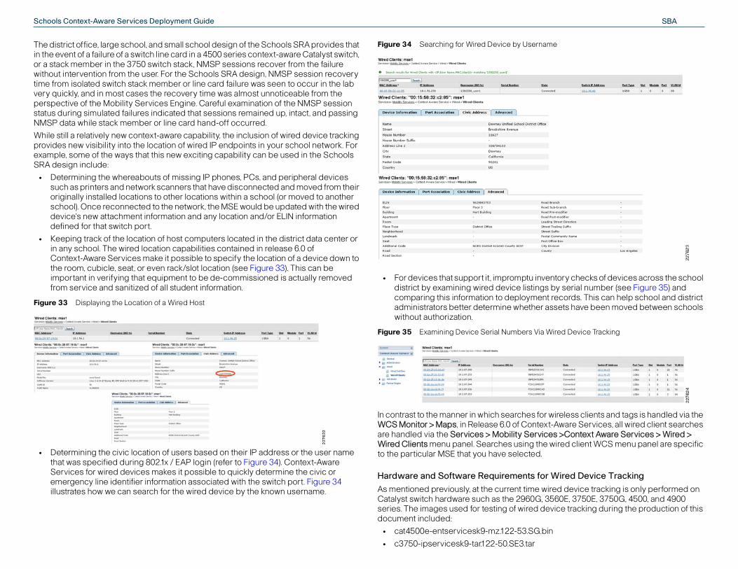
SBASchools Context-Aware Services Deployment Guide
y checks of devices across the school erial number (see Figure 35) and
ords. This can help school and district ts have been moved between schools
Device Tracking
less clients and tags is handled via the are Services, all wired client searches Context Aware Services > Wired > d client WCS menu panel are specific
ed Device Tracking
device tracking is only performed on E, 3750E, 3750G, 4500, and 4900 tracking during the production of this
The district office, large school, and small school design of the Schools SRA provides that in the event of a failure of a switch line card in a 4500 series context-aware Catalyst switch, or a stack member in the 3750 switch stack, NMSP sessions recover from the failure without intervention from the user. For the Schools SRA design, NMSP session recovery time from isolated switch stack member or line card failure was seen to occur in the lab very quickly, and in most cases the recovery time was almost unnoticeable from the perspective of the Mobility Services Engine. Careful examination of the NMSP session status during simulated failures indicated that sessions remained up, intact, and passing NMSP data while stack member or line card hand-off occurred.
While still a relatively new context-aware capability, the inclusion of wired device tracking provides new visibility into the location of wired IP endpoints in your school network. For example, some of the ways that this new exciting capability can be used in the Schools SRA design include:
• Determining the whereabouts of missing IP phones, PCs, and peripheral devices such as printers and network scanners that have disconnected and moved from their originally installed locations to other locations within a school (or moved to another school). Once reconnected to the network, the MSE would be updated with the wired device's new attachment information and any location and/or ELIN information defined for that switch port.
• Keeping track of the location of host computers located in the district data center or in any school. The wired location capabilities contained in release 6.0 of Context-Aware Services make it possible to specify the location of a device down to the room, cubicle, seat, or even rack/slot location (see Figure 33). This can be important in verifying that equipment to be de-commissioned is actually removed from service and sanitized of all student information.
Figure 33 Displaying the Location of a Wired Host
• Determining the civic location of users based on their IP address or the user name that was specified during 802.1x / EAP login (refer to Figure 34). Context-Aware Services for wired devices makes it possible to quickly determine the civic or emergency line identifier information associated with the switch port. Figure 34 illustrates how we can search for the wired device by the known username.
Figure 34 Searching for Wired Device by Username
• For devices that support it, impromptu inventordistrict by examining wired device listings by scomparing this information to deployment recadministrators better determine whether assewithout authorization.
Figure 35 Examining Device Serial Numbers Via Wired
In contrast to the manner in which searches for wireWCS Monitor > Maps, in Release 6.0 of Context-Aware handled via the Services > Mobility Services >Wired Clients menu panel. Searches using the wireto the particular MSE that you have selected.
Hardware and Software Requirements for Wir
As mentioned previously, at the current time wired Catalyst switch hardware such as the 2960G, 3560series. The images used for testing of wired devicedocument included:
• cat4500e-entservicesk9-mz.122-53.SG.bin
• c3750-ipservicesk9-tar.122-50.SE3.tar
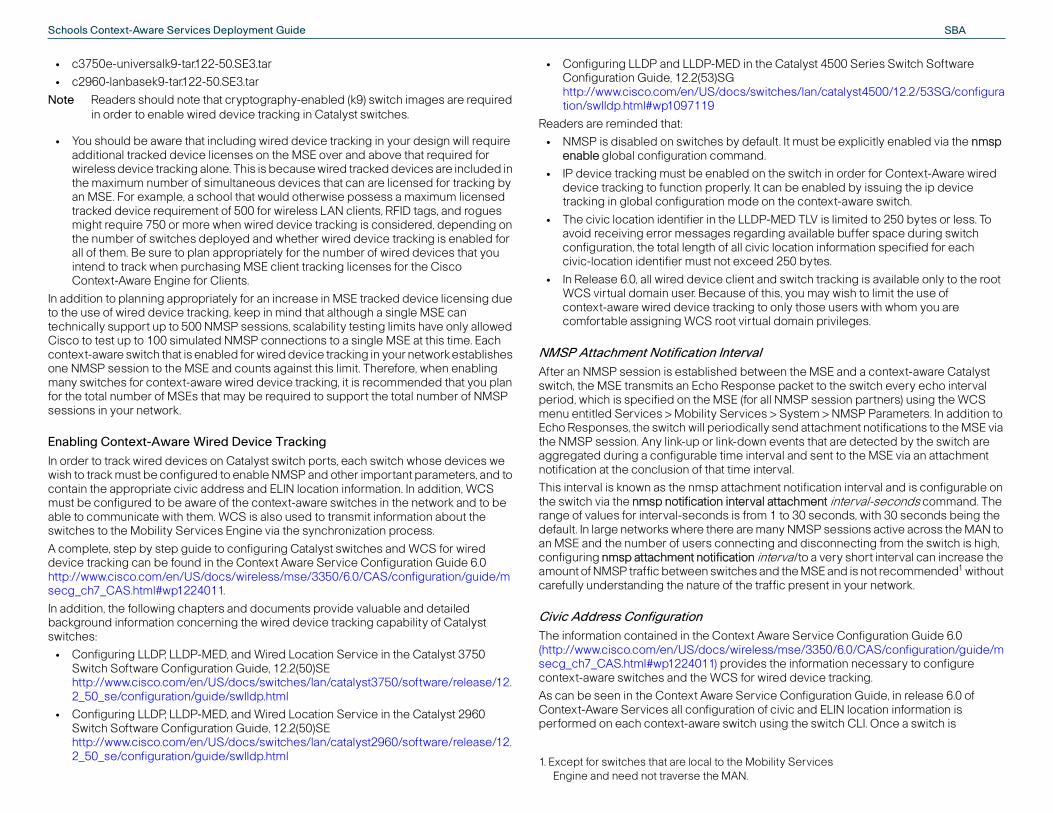
SBASchools Context-Aware Services Deployment Guide
yst 4500 Series Switch Software
an/catalyst4500/12.2/53SG/configura
ust be explicitly enabled via the nmsp
itch in order for Context-Aware wired nabled by issuing the ip device
ontext-aware switch.
LV is limited to 250 bytes or less. To ilable buffer space during switch n information specified for each ytes.
h tracking is available only to the root may wish to limit the use of ose users with whom you are in privileges.
MSE and a context-aware Catalyst et to the switch every echo interval session partners) using the WCS
em > NMSP Parameters. In addition to ttachment notifications to the MSE via that are detected by the switch are sent to the MSE via an attachment
fication interval and is configurable on ent interval-seconds command. The
seconds, with 30 seconds being the SP sessions active across the MAN to isconnecting from the switch is high, a very short interval can increase the SE and is not recommended1 without
sent in your network.
rvice Configuration Guide 6.0 3350/6.0/CAS/configuration/guide/mrmation necessary to configure
vice tracking.
figuration Guide, in release 6.0 of nd ELIN location information is switch CLI. Once a switch is
rvices
• c3750e-universalk9-tar.122-50.SE3.tar
• c2960-lanbasek9-tar.122-50.SE3.tar
Note Readers should note that cryptography-enabled (k9) switch images are required in order to enable wired device tracking in Catalyst switches.
• You should be aware that including wired device tracking in your design will require additional tracked device licenses on the MSE over and above that required for wireless device tracking alone. This is because wired tracked devices are included in the maximum number of simultaneous devices that can are licensed for tracking by an MSE. For example, a school that would otherwise possess a maximum licensed tracked device requirement of 500 for wireless LAN clients, RFID tags, and rogues might require 750 or more when wired device tracking is considered, depending on the number of switches deployed and whether wired device tracking is enabled for all of them. Be sure to plan appropriately for the number of wired devices that you intend to track when purchasing MSE client tracking licenses for the Cisco Context-Aware Engine for Clients.
In addition to planning appropriately for an increase in MSE tracked device licensing due to the use of wired device tracking, keep in mind that although a single MSE can technically support up to 500 NMSP sessions, scalability testing limits have only allowed Cisco to test up to 100 simulated NMSP connections to a single MSE at this time. Each context-aware switch that is enabled for wired device tracking in your network establishes one NMSP session to the MSE and counts against this limit. Therefore, when enabling many switches for context-aware wired device tracking, it is recommended that you plan for the total number of MSEs that may be required to support the total number of NMSP sessions in your network.
Enabling Context-Aware Wired Device Tracking
In order to track wired devices on Catalyst switch ports, each switch whose devices we wish to track must be configured to enable NMSP and other important parameters, and to contain the appropriate civic address and ELIN location information. In addition, WCS must be configured to be aware of the context-aware switches in the network and to be able to communicate with them. WCS is also used to transmit information about the switches to the Mobility Services Engine via the synchronization process.
A complete, step by step guide to configuring Catalyst switches and WCS for wired device tracking can be found in the Context Aware Service Configuration Guide 6.0 http://www.cisco.com/en/US/docs/wireless/mse/3350/6.0/CAS/configuration/guide/msecg_ch7_CAS.html#wp1224011.
In addition, the following chapters and documents provide valuable and detailed background information concerning the wired device tracking capability of Catalyst switches:
• Configuring LLDP, LLDP-MED, and Wired Location Service in the Catalyst 3750 Switch Software Configuration Guide, 12.2(50)SE http://www.cisco.com/en/US/docs/switches/lan/catalyst3750/software/release/12.2_50_se/configuration/guide/swlldp.html
• Configuring LLDP, LLDP-MED, and Wired Location Service in the Catalyst 2960 Switch Software Configuration Guide, 12.2(50)SE http://www.cisco.com/en/US/docs/switches/lan/catalyst2960/software/release/12.2_50_se/configuration/guide/swlldp.html
• Configuring LLDP and LLDP-MED in the CatalConfiguration Guide, 12.2(53)SG http://www.cisco.com/en/US/docs/switches/ltion/swlldp.html#wp1097119
Readers are reminded that:
• NMSP is disabled on switches by default. It menable global configuration command.
• IP device tracking must be enabled on the swdevice tracking to function properly. It can be etracking in global configuration mode on the c
• The civic location identifier in the LLDP-MED Tavoid receiving error messages regarding avaconfiguration, the total length of all civic locatiocivic-location identifier must not exceed 250 b
• In Release 6.0, all wired device client and switcWCS virtual domain user. Because of this, youcontext-aware wired device tracking to only thcomfortable assigning WCS root virtual doma
NMSP Attachment Notification IntervalAfter an NMSP session is established between theswitch, the MSE transmits an Echo Response packperiod, which is specified on the MSE (for all NMSPmenu entitled Services > Mobility Services > SystEcho Responses, the switch will periodically send athe NMSP session. Any link-up or link-down eventsaggregated during a configurable time interval andnotification at the conclusion of that time interval.
This interval is known as the nmsp attachment notithe switch via the nmsp notification interval attachmrange of values for interval-seconds is from 1 to 30default. In large networks where there are many NMan MSE and the number of users connecting and dconfiguring nmsp attachment notification interval toamount of NMSP traffic between switches and the Mcarefully understanding the nature of the traffic pre
Civic Address ConfigurationThe information contained in the Context Aware Se(http://www.cisco.com/en/US/docs/wireless/mse/secg_ch7_CAS.html#wp1224011) provides the infocontext-aware switches and the WCS for wired de
As can be seen in the Context Aware Service ConContext-Aware Services all configuration of civic aperformed on each context-aware switch using the
1. Except for switches that are local to the Mobility SeEngine and need not traverse the MAN.

SBASchools Context-Aware Services Deployment Guide
ffice”
County 6037"
ffice”
configured with the desired civic and ELIN location information, the switch will share all of the configured port information with the MSE when the NMSP session is initially established and will periodically update the MSE if any location updates are performed.
Note Readers should find the following IETF RFC documents helpful in better understanding the types of values that should be specified for the various civic location fields: RFC 4776 (http://www.ietf.org/rfc/rfc4776.txt), RFC 4589 (http://www.ietf.org/rfc/rfc4589.txt), and RFC 5139 (http://www.ietf.org/rfc/rfc5139.txt).
During the course of our lab testing, we discovered other useful facets of information regarding civic location and ELIN configuration in Catalyst switch IOS releases 12.2-52(SE) and 12.2-53(SG):
• Global Scope of Civic and ELIN location—Civic address or ELIN information must be configured at a global level and then assigned to each switch interface using the appropriate civic or ELIN location identifier. Globally defined civic address parameters (such as the building, county, postal code, floor, and so on) cannot be individually over-ridden at the interface level in release 6.0. If more than one switch port shares the same civic location or ELIN, then the same globally specified civic and ELIN location identifiers can be used on each switch port interface. However, if all ports possess unique civic address characteristics, then uniquely specified global civic address parameters for each port must be used. This can be seen in the following example where three unique civic location identifiers are applied to three different ports (Gi1/0/3 - 1/0/5). The test application server that is being tested on port Gi 1/0/6 is in the same physical location as the device connected to port Gi1/0/5, hence they share civic-location identifier 3.location civic-location identifier 1
additional-code “NCES District 611460 County 6037"
building “Hart Building”
city Downey
country US
county “Los Angeles”
floor “Floor 3"
name “Downey Unified School District Office”
postal-code 90241
state California
street-group “Brookshire Avenue”
number 11627
room 300
seat 3H103
type-of-place “District Office”
!
location civic-location identifier 2
additional-code “NCES District 611460 County 6037"
building “Hart Building”
city Downey
country US
county “Los Angeles”
floor “Floor 3"
name “Downey Unified School District O
postal-code 90241
state California
street-group “Brookshire Avenue”
number 11627
room 300
seat 3H104
type-of-place “District Office”
!
location civic-location identifier 3
additional-code “NCES District 611460
building “Hart Building”
city Downey
country US
county “Los Angeles”
floor “Floor 3"
name “Downey Unified School District O
postal-code 90241
state California
street-group “Brookshire Avenue”
number 11627
room 300
seat 3H105
type-of-place “District Office”
!
interface GigabitEthernet0/3
description 802.1x data access only
location civic-location-id 1
switchport access vlan 88
switchport mode access
authentication port-control auto
dot1x pae authenticator
!
interface GigabitEthernet0/4
description 802.1x data access only
location civic-location-id 2
switchport access vlan 88
switchport mode access
authentication port-control auto
dot1x pae authenticator
!
interface GigabitEthernet0/5
description 802.1x data access only
location civic-location-id 3
switchport access vlan 88
switchport mode access

SBASchools Context-Aware Services Deployment Guide
porting device attachments to the ce the number of MSE tracked device ng of device attachments on select is expected. Recall that in release 6.0, e tracking entirely on a per MSE basis, es that are tracked in each MSE at this herefore, any such limiting must be with selected switches entirely (no ct switch ports on a context-aware nts normally.
n a switch where NMSP has been ttachment suppress command should e tracking is not desired. The nmsp o configure the interface to not send rvices Engine (MSE).
Mobility Services > Context Aware specifically limit or block (by MAC sed that these address filters also any filtering specifications that you set allow tracking of not only your wireless ices that have been blocked from
e viewable under the “Blocked MACs” formation regarding how to configure iltering Parameters section of the 6.0 3350/6.0/CAS/configuration/guide/m
lity and acceptable CAS performance ation of QoS to NMSP data flows ntext-aware Ethernet switches in the oS should be applied ideally in both E implementations, however, it is
E at the district site and remote WLAN the schools.
roperly for NMSP sessions the NMSP d marked as close as possible to their arking of NMSP data flows should ed.
on, classification and marking of NMSP istrict design containing:
0 for distribution, with an MSE located
0 switch stack for distribution.
authentication port-control auto
dot1x pae authenticator
!
interface GigabitEthernet0/6
description test school local RFID gate application server
location civic-location-id 3
switchport access vlan 56
switchport mode access
!
• Civic location additional-location-information subcommand—During the course of our testing we found the additional-location-information subcommand useful in adding miscellaneous information about devices that can be displayed on the civic address tab of the WCS wired clients display under “Address Line 2". In our testing, we made use of this facility to label the rack and position location of various servers and other devices that are deployed in a common location. Figure 36 illustrates how the information entered using additional-location-information is then displayed on the civic address tab of the WCS wired clients display for the device (indicated by the red arrow). Below the configuration for the switch port, we can see the results of displaying the civic location for the switch interface using the location civic-location interface interface command.
Figure 36 Additional-Location-Information
• Civic Location street-group subcommand—In order to display a value under the street name component on the civic address tab of the WCS wired clients display, we found it was necessary to use the civic location street-group subcommand in the switch configuration. If we look again at the left hand portion of Figure 36, we can see the street-group is specified as “Brookshire Avenue”. On the right hand of Figure 36, we see that this value appears under the civic address tab of the WCS wired clients display under the label “Street”.
Excluding Device Tracking on Select Switch Ports
In the majority of cases, when using context-aware wired device tracking, it is usually acceptable to simply enable NMSP on the switch and allow the attachment status of all ports to be reported to the MSE. In this way, the attachment status and any location or ELIN information specified for each port in the switch is reported and can be accessed from the MSE. However, in some cases, it might be desirable to enable wired device tracking on
a switch, but exclude selected switch ports from reMSE. A reason for doing this might be to help redulicenses required by eliminating the NMSP reportiports where not much chance of device migration while it is possible to enable or disable wired devicit is not possible to limit the number of wired devictime (i.e., wired device tracking is either on or off). Tdone manually by either disabling NMSP sessionsnmsp enable) or disabling only the tracking of seleswitch that is otherwise reported device attachme
To disable device tracking for select switch ports oenabled, the switch interface configuration nmsp abe specified on each switch interface where devicattachment suppress interface command is used tany attachment notifications to a Cisco Mobility Se
If you are using Location MAC Filtering (Services >Service > Administration> Filtering Parameters) to address) tracked wireless clients and tags, be adviapply to wired device clients as well. Make sure thatusing Location MAC Filtering are flexible enough toclients and tags, but wired devices as well. Any devlocation tracking as a result of a defined filter will blisting on the Filtering Parameters page. Detailed inLocation MAC filtering can be found in Modifying FCisco Context-Aware Service Configuration Guide(http://www.cisco.com/en/US/docs/wireless/mse/secg_ch7_CAS.html#wp1100062).
Classification and Marking of NMSP Sessions
A vital component in assuring NMSP session stabiduring periods of network congestion is the applicbetween the MSE and any WLAN controllers or coSchools SRA design. Classification, marking and Qcases of locally deployed as well as centralized MSespecially important when using a centralized MScontrollers and context-aware Ethernet switches in
In order to ensure that QoS prioritization can occur pdata flows must be properly identified, classified anpoints of origin. This section explains where such moccur in the network, and how it should be perform
Figure 37 provides an example of where identificatidata flows should occur in the case of the school d
• A district office with adjoining data center
• A school site that is based on the Catalyst 450at the school
• A school site that is based on the Catalyst 375

SBASchools Context-Aware Services Deployment Guide
using this criteria
DSCP value to the filtered traffic using
he MSE is attached.
ort 16113, we can make use of this to priately.
ill mark NMSP traffic inbound to the to as DSCP 18, Assured Forwarding
down any NMSP traffic exceeding this
d-dscp-transmit
ttached, it is imperative that the policy map to the
g the network originating at the WLC is eft unchanged, when congestion is
traffic marked in this fashion will be ot desirable and we shall address it in
e us with the ability to mark the NMSP nd mark this traffic inside the network. ration is performed as close in the re, in Figure 37, the points at which this
ng from both normally active as well as ssified and marked.
In Figure 37, we have identified several points where classification and remarking needs to occur in order to properly mark NMSP traffic inbound from WLAN controllers and context aware switches, and outbound from Mobility Services Engines. These points are indicated by the yellow and red numbered circles.
Figure 37 Points of NMSP Classification and Marking
NMSP Traffic Flows Originating At The MSE
NMSP sessions between the MSE, WLAN controllers and context-aware switches are bi-directional in nature. Here, we are referring simply to that portion of any flow whose source address is that belonging to the Mobility Services Engine. Since the Mobility Services Engine does not mark the DSCP for the NMSP traffic it transmits into the network, all such traffic originating at the MSE will contain the default DSCP marking of 0x00. Left unchanged, when congestion is encountered in the Schools SRA design all NMSP traffic marked in this fashion will be treated with the lowest priority. This increases the probability that NMSP session data will be dropped in the network during periods of congestion. Left unchecked, this can result in NMSP session stability issues, and poor context-aware performance. Clearly, this is not desirable. We can avoid this by classifying and remarking NMSP data appropriately, as described in this section.
Since the MSE currently does not support classification and marking the DSCP value assigned to its traffic, we must make use of the classification and marking capabilities available to us in the Ethernet switch to which the MSE is attached. Thus, where 1 appears in Figure 37, we will:
• Define the criteria to select our NMSP traffic
• Define a class-map that will filter NMSP traffic
• Define a service-policy to assign our desired the class-map
• Apply the service-policy to the port to which t
Since we know that NMSP traffic will involve TCP pidentify NMSP traffic and proceed to mark it appro
The following example defines a policy map that wnetwork from the MSE as DSCP 0x12 (also referred21), police down to 10 Mbps per 8k burst, and mark accordingly using the QoS map.mls qos
!
class-map match-all CAS
match access-group name NMSP
!
policy-map MSE-Policy
class CAS
set dscp af21
police 10000000 8000 exceed-action police
!
ip access-list extended NMSP
remark Identify NMSP traffic
permit tcp any any eq 16113
permit tcp any eq 16113 any
On the switch interface where the MSE is aservice-policy statement appears to assigninterface. For example:
interface GigabitEthernet1/0/2
description Mobility Services Engine MSE1
.
.
service-policy input MSE-Policy
NMSP Traffic Generated By WLAN Controllers
As was the case with the MSE, NMSP traffic enterinalso marked with the default DSCP value of 0x00. Lencountered in the Schools SRA design all NMSPtreated with the lowest priority. Once again, this is nthis section.
Like the MSE, the WLAN controller does not providtraffic as we see fit, thus we must instead classify aIn accordance with general best practices, this openetwork as possible to the WLAN controller. Therefoshould occur are shown by 2. Note that traffic comiany optional backup WLAN controllers must be cla
Services Block
MetropolitanArea
Network
School Site Cisco 4500Distribution
WLANController
Cisco 2960G Cisco 3560G Cisco 2960G Cisco 3750G
Cisco 2960G Cisco 3750G
AccessControlSystem
DistrictOffice
IPIP
WLANController
WirelessControl System
Optional BackupWLAN Controller(s)
AccessControlSystem
School SiteCisco 3750 Stack
Distribution
WLANController
AccessControlSystem
IP
2278
95
IP IPIP
132
2
4
3
3
2
4
3
2
4
3
3
Mobility ServicesEngine
MSE
1Mobility Services
Engine
MSE

SBASchools Context-Aware Services Deployment Guide
itch, the scenario is a bit different. The igned to the port-channel group used
aces. Thus, our recommended ution would be as follows:
ult
aces gig2/11, gig3/11
hannel6
hannel6
The method used to accomplish this classification and marking for WLAN controllers is very similar to that presented in the previous section for the MSE. However, since the WLAN controller is attached to the Ethernet switch using an Etherchannel port-channel group, there will be some relevant differences relating to whether the port-channel attachment is to a Catalyst 3750 switch stack or Catalyst 4500 distribution switch.
For example, when using the Catalyst 3750 switch stack in distribution, the following configuration would apply:mls qos
!
class-map match-all CAS
match access-group name NMSP
!
policy-map CAS-Policy
class CAS
set dscp af21
police 10000000 8000 exceed-action policed-dscp-transmit
!
ip access-list extended NMSP
remark Identify NMSP traffic
permit tcp any any eq 16113
permit tcp any eq 16113 any
The 3750 switch stack would also have a port-channel definition that would refer to the two physical Ethernet interfaces comprising the port-channel group.interface Port-channel4
description EC trunk to school 1266, WLC, interfaces gig1/0/28, 2/0/28
It is important to note that the 3750 switch stack does not support the use of a policy-map statement on a port-channel definition. In order to assure that NMSP traffic originating at the WLAN Controller in-bound to the network is properly classified and marked, ensure that a service-policy statement appears on each of the two physical interfaces that comprise the WLAN controller port-channel group in the 3750 switch stack. For example:
interface GigabitEthernet1/0/28
description trunk to school 1266 WLC, port-channel4
.
.
mls qos trust dscp
channel-group 4 mode on
service-policy input CAS-Policy
!
interface GigabitEthernet2/0/28
description trunk to school 1266 WLC, port-channel4
.
.
mls qos trust dscp
channel-group 4 mode on
service-policy input CAS-Policy
When using the Catalyst 4500 as the distribution swCatalyst 4500 requires the service-policy to be assfor the WLAN controller, and not the physical interfconfiguration when using a Catalyst 4500 in distrib!
class-map match-all CAS
match access-group name NMSP
!
policy-map CAS-Policy
class CAS
set dscp af21
police cir 10000000
conform-action transmit
exceed-action set-dscp-transmit defa
!
ip access-list extended NMSP
remark Identify NMSP traffic
permit tcp any any eq 16113
permit tcp any eq 16113 any
!
interface Port-channel6
description trunk to district WLC, interf
.
.
service-policy input CAS-Policy
!
!
interface GigabitEthernet2/11
description trunk to district WLC, port-c
.
.
channel-group 6 mode on
!
interface GigabitEthernet3/11
description trunk to district WLC, port-c
.
.
channel-group 6 mode on
!

SBASchools Context-Aware Services Deployment Guide
class-map and policy-map can be olicy input CAS-Policy statement stack that comprise the port-channel
nnel-attached WLAN controller, a el group definition used for the 2960G.
tch with a context-aware 2960G at the olicy statement to the port-channel in a similar fashion to that described r.
ts
g and part number information, see cisco.com/en/US/prod/collateral/wireless/p01/ps6305/product_data_sheet0900aecd8
ml
d tag licensing information, see cisco.com/en/US/prod/collateral/wireless/p42/data_sheet_c07-473865.html
d tag licensing information, see cisco.com/en/US/prod/collateral/wireless/p42/data_sheet_c07-473865.html
Cisco Wireless LAN Controller
Cisco Wireless LAN Controller
ol distribution switch; must use crypto (K9) S for wired devices is desired
ol distribution switch; must use crypto (K9) S for wired devices is desired
tch; must use crypto (K9) image if CAS for es is desired
tch; must use crypto (K9) image if CAS for es is desired
et 1250 Series Wireless Access Point
et 1140 Series Wireless Access Point
mponent; for licensing information, see cisco.com/en/US/prod/collateral/wireless/p01/ps7305/product_data_sheet0900aecd8
ml
m http://www.aeroscout.com/; RFID tags are ly if RFID tracking is desired
m http://www.aeroscout.com/; RFID tags are ly if RFID tracking is desired
t trigger, optional RFID enhancement; del recommended if outdoor placement is
NMSP Traffic Generated By Context-Aware Switches
As you will recall, specific models of Catalyst switches described earlier in this document (such as the 2960G, 3560, 3750, 4500, 4900 and others) can provide context-aware information to the MSE relating to IP-based attached devices. When this capability is enabled in a context-aware switch, the switch itself participates in an NMSP session with the MSE. This NMSP session is separate and independent of any NMSP sessions that may pass through the switch to or from attached devices (such as the WLAN controllers described earlier, or other downstream context-aware switches).
In order to ensure that the NMSP traffic originating at these switches is treated appropriately in the network during times of congestion, it is important that we properly classify the NMSP data originating at the context-aware switch and destined in-bound to the network for the MSE. Depending on the type of switch used, the exact method we shall use to apply this classification and marking will vary.
Layer-Three Context-Aware Switches
In the case of context-aware Layer-3 switches such as the 3750, 3560 and 4500, we can make use of local policy routing to assign an IP precedence 2 (DSCP 0x10) to NMSP traffic originating from the switch itself. Local policy routing in this fashion is performed internal to the context-aware L3 switch originating the NMSP traffic, and the traffic is marked prior to being introduced into the network. At the locations in Figure 37 marked with 3, we can perform the required classification using a local policy route-map as follows:ip local policy route-map switch-NMSP
!
route-map switch-NMSP permit 10
match ip address NMSP
set ip precedence 2
set ip tos max-throughput
!
ip access-list extended NMSP
permit tcp any any eq 16113
permit tcp any eq 16113 any
!
Layer Two Context-Aware Switches
However, the use of the Cisco 2960G context-aware Layer-2 switch in the access layer presents a challenge. Local policy routing is not supported by the L2-only 2960G. Therefore, as a workaround, we must classify and mark the NMSP traffic originating from the 2960G at the next switch upstream to it in the network. In the Schools SRA design, this upstream switch would be the 3750 switch stack or 4500 distribution switch. In Figure 37, the points at where this must be performed are indicated by 4.
Note that in the Schools SRA design, the 2960G access layer switches are attached to the distribution switches using an Etherchannel port-group, in a fashion very similar to that of the WLAN controllers. Therefore, similar techniques can be used to classify and mark the NMSP traffic originating at the 2960G and coming across the Etherchannel link.
Thus, for a 3750 switch stack used in distribution, aapplied as described previously, and the service-papplied to the physical interfaces in the 3750 switchgroup to the 2960G switch. Just as for an Etherchaservice-policy cannot be applied to the port-chann
When using a Catalyst 4500 as the distribution swiaccess layer, apply the service-policy input CAS-Pgroup definition for the 2960G. This would be doneearlier for a Etherchannel-attached WLAN controlle
Hardware/Software Releases
Table 3 Hardware/Software Releases
Component Version Commen
Wireless Control System 6.0.132.0 For licensinhttp://www.s5755/ps6304b4646.ht
Mobility Services Engine 3350 6.0.85.0 For client anhttp://www.s9733/ps97
Mobility Services Engine 3310 6.0.85.0 For client anhttp://www.s9733/ps97
WLAN Controller 4404 6.0.182.0 Standalone
WLAN Controller 4402 6.0.182.0 Standalone
Catalyst 4500 12.2.53-SG Large schoimage if CA
Catalyst 3750E Switch Stack 12.2(52)SE Small schoimage if CA
Catalyst 2960G 12.2(52)SE Access swiwired devic
Catalyst 3750E 12.2(52)SE Access swiwired devic
LAP1252 Access Point 6.0.182.0 Cisco Airon
LAP1142 Access Point 6.0.182.0 Cisco Airon
WCS Navigator 1.5.132.0 Optional cohttp://www.s5755/ps63065bd19.ht
AeroScout T2 RFID Asset Tag 4.33 Available frorequired on
AeroScout T3 RFID Asset Tag 6.05 Available frorequired on
AeroScout EX-3200 Exciter 33007/60007 ChokepoinEX-2000 monecessary

SBASchools Context-Aware Services Deployment Guide
antage of the strong security, hat are built into Cisco Context-Aware
plementation, we also offer services optimizing the performance of a
ociated technologies and strategies.
ireless site survey of your facility rmation on Cisco bundled planning,
961/ps6899/ps8306/services_overvireless LAN Specialized Partner, refer CATR/openAdvanceSearch.do.
Context-Aware Services—General Best Practice ReferencesThe following are recommended references with regard to general best practice deployment recommendations for Cisco Unified Networks making use of Context-Aware Services release 6.0:
• A cornerstone of a successful design is knowledge of established best practices. Thus, it is highly recommended that you become familiar with the material presented in the following documents:
– Context-Aware Solution Deployment Guide http://www.cisco.com/en/US/products/ps9742/products_tech_note09186a00809d1529.shtml
– VoWLAN Design Guide 4.1 http://www.cisco.com/en/US/docs/solutions/Enterprise/Mobility/vowlan/41dg/vowlan41dg-book.html
– Context-Aware Services Configuration Guide, Release 6.0 http://www.cisco.com/en/US/docs/wireless/mse/3350/6.0/CAS/configuration/guide/CAS_60.html
– Wireless LAN Controller Configuration Guide, Release 6.0 http://www.cisco.com/en/US/docs/wireless/controller/6.0/configuration/guide/Controller60CG.html
– Wireless Control System Configuration Guide, Release 6.0 http://www.cisco.com/en/US/docs/wireless/wcs/6.0/configuration/guide/WCS60cg.html
• If you intend to make use of RFID tags in your Context-Aware solution, it is also recommended that you become familiar with the following document which explains the operation of the Cisco Context-Aware Engine for Tags:
– AeroScout Context-Aware Engine for Tags for Cisco MSE User Guide, version 3.2 http://support.aeroscout.com
• If you intend to track the location and status of wired devices attached to Catalyst Ethernet switches, it is recommended that you familiarize yourself with the appropriate configuration guide for this feature in the switches you will be using. For example:
– Catalyst 2960 Switch Software Configuration Guide, 12.2(50)SE http://www.cisco.com/en/US/docs/switches/lan/catalyst2960/software/release/12.2_50_se/configuration/guide/scg.html
– Catalyst 3750 Switch Software Configuration Guide, 12.2(50)SE http://www.cisco.com/en/US/docs/switches/lan/catalyst3750/software/release/12.2_50_se/configuration/guide/scg.html
– Catalyst 4500 Series Switch Software Configuration Guide, 12.2(53)SG http://www.cisco.com/en/US/docs/switches/lan/catalyst4500/12.2/53SG/configuration/config.html
During any deployment of Context-Aware Services and Cisco Unified Wireless Networks, detailed site surveys should be performed by a Cisco Wireless LAN Specialized Partner with expertise in voice, high speed data, and Context-Aware wireless network deployment. Cisco Systems also offers a complete package of bundled design and deployment services via the Cisco Advanced Services team. Cisco and our Wireless LAN Specialized Partners offer Context-Aware Design and Implementation Services to help you successfully deploy enterprise-class wireless connectivity. These services include the installation and configuration of crucial components such as the Mobility
Services Engine (MSE), helping you to take full advmanagement, and investment protection features tcomponents. In addition to planning, design, and imbased on proven methodologies for operating andContext-Aware Mobility solution, along with its ass
Note The importance of a properly performed wcannot be over-emphasized. For more infodesign, and deployment services, refer to http://www.cisco.com/en/US/services/ps2iew_context_aware.pdf. To locate a Cisco Wto http://tools.cisco.com/WWChannels/LO