Embed Size (px)
Citation preview
1SCARA robots
SCARA robots
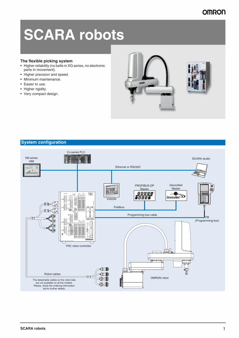
The flexible picking system• Higher reliability (no belts in XG series, no electronic
parts in movement).• Higher precision and speed.• Minimum maintenance.• Easier to use.• Higher rigidity.• Very compact design.
System configuration
PB
MOTOR
XM
YM
ZM
RM
PWR
SRV
SAFETY
COM
STD.DIO
ROBI/O
ZR
OP.1 OP.3
OP.2 OP.4RGEN
ACIN
N
P
N1
L1
L
N
SEL
BATTZR
XYBATT
ROB
XY
I/O
PIN13-14EXT.E-STOP
ERR
YRC
OMRON
PROFIBUS-DPMaster
DeviceNetMaster
Fieldbus
Robot cables
Ethernet or RS232C
YRC robot controller
CJ-series PLC
VISION
Programming box cable PB (Programming box)
OMRON robot
SCARA studio
The detachable cables on the robot sideare not available on all the models.
Please, check the ordering informationlist for further details.
NS-seriesHMI
2
YRC Robot controller
Specifications
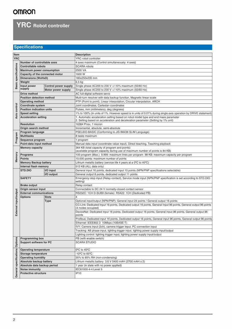
Item DescriptionYRC YRC robot controller
Bas
ic s
pec
ific
atio
ns Number of controllable axes 4 axes maximum (Control simultaneously: 4 axes)
Controllable robots SCARA robotsMaximum power consumption 2500 VACapacity of the connected motor 1600 WDimensions (WxHxD) 180x250x235 mmWeight 6.5 kgInput power supply
Control power supply Single phase AC200 to 230 V +/-10% maximum (50/60 Hz)Motor power supply Single phase AC200 to 230 V +/-10% maximum (50/60 Hz)
Axi
s co
ntr
ol
Drive method AC full-digital software servoPosition detection method Multi-turn resolver with data backup function, Magnetic linear scaleOperating method PTP (Point to point), Linear interpolation, Circular interpolation, ARCHCoordinate system Joint coordinates, Cartesian coordinatesPosition indication units Pulses, mm (millimeters), deg (degrees)Speed setting 1% to 100% (In units of 1%. However speed is in units of 0.01% during single-axis operation by DRIVE statement)Acceleration setting 1. Automatic acceleration setting based on robot model type and end mass parameter
2. Setting based on acceleration and deceleration parameter (Setting by 1% unit)Resolution 16384 P/rev, 1 micronOrigin search method Incremental, absolute, semi-absolute
Pro
gra
m
Program language PSEUDO-BASIC (Conforming to JIS B8439 SLIM Language)Multitasks 8 tasks maximumSequence program 1 programPoint-data input method Manual data input (coordinate value input), Direct teaching, Teaching playback
Mem
ory
Memory capacity 364 KB (total capacity of program and points)(avaliable program capacity during use of maximum number of points is 84 KB)
Programs 100 program (Max.) 9.999: maximum lines per program 98 KB: maximum capacity per program Points 10.000 points: maximum number of pointsMemory Backup battery Lithium metallic battery (service life 4 years at a 0ºC to 40ºC)Internal flash memory 512 KB (ALL data only)
Ext
ern
al in
pu
t/o
utp
ut
STD.DIO I/O input General input 16 points, dedicated input 10 points (NPN/PNP specifications selectable)I/O output General output 8 points, dedicated output 11 points
SAFETY Emergency stop input (Relay contact), Service mode input (NPN/PNP specification is set according to STD.DIO setting)
Brake output Relay contactOrigin sensor input Connectable to DC 24 V normally-closed contact sensorExternal communications RS232C: 1CH D-SUB9 (female) RS422: 1CH (Dedicated PB)Options Slots 4
Type Optional input/output (NPN/PNP): General input 24 points / General output 16 pointsCC-Link: Dedicated input 16 points, Dedicated output 16 points, General input 96 points, General output 96 points (4 nodes occupied)DeviceNet: Dedicated input 16 points, Dedicated output 16 points, General input 96 points, General output 96 pointsProfibus: Dedicated input 16 points, Dedicated output 16 points, General input 96 points, General output 96 pointsEthernet: IEEE802.3 10Mbps (10BASE-T)IVY: Camera input (2ch), camera trigger input, PC connection inputTracking: AB phase input, lighting trigger input, lighting power supply input/outputLighting control: lighting trigger input, lighting power supply input/output
Op
tio
ns Programming box PB (with enable switch)
Support software for PC SCARA STUDIO
Gen
eral
sp
ecif
icat
ion
s Operating temperature 0ºC to 40ºCStorage temperature -10ºC to 65ºCOperating humidity 35% to 85% RH (non-condensing)Absolute backup battery Lithium metallic battery 3.6 V 5400 mAH (2700 mAH x 2)Absolute data backup period 1 year (in state with no power applied)Noise immunity IEC61000-4-4 Level 3Protective structure IP10
SCARA robots
SCARA robots 3
YRC Robot controller
:
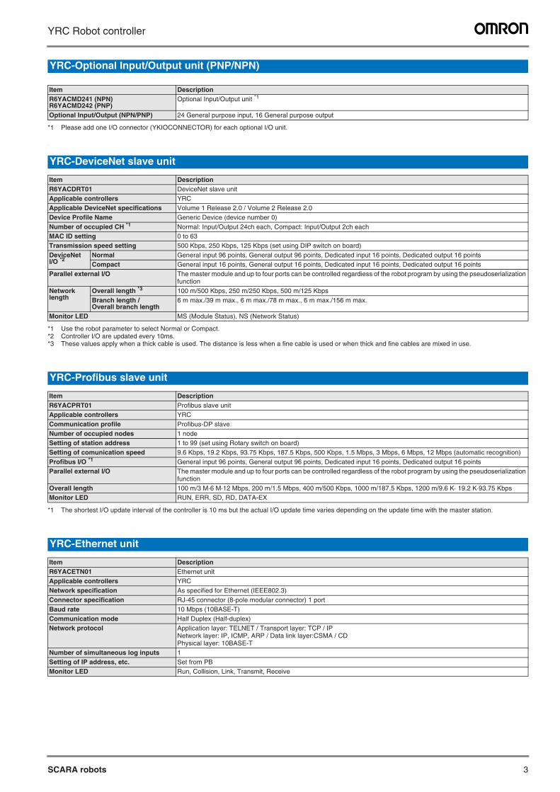
YRC-Optional Input/Output unit (PNP/NPN)
Item DescriptionR6YACMD241 (NPN)R6YACMD242 (PNP)
Optional Input/Output unit *1
*1 Please add one I/O connector (YKIOCONNECTOR) for each optional I/O unit.
Optional Input/Output (NPN/PNP) 24 General purpose input, 16 General purpose output
YRC-DeviceNet slave unit
Item DescriptionR6YACDRT01 DeviceNet slave unitApplicable controllers YRCApplicable DeviceNet specifications Volume 1 Release 2.0 / Volume 2 Release 2.0Device Profile Name Generic Device (device number 0)Number of occupied CH *1
*1 Use the robot parameter to select Normal or Compact.
Normal: Input/Output 24ch each, Compact: Input/Output 2ch eachMAC ID setting 0 to 63Transmission speed setting 500 Kbps, 250 Kbps, 125 Kbps (set using DIP switch on board)DeviceNetI/O *2
*2 Controller I/O are updated every 10ms.
Normal General input 96 points, General output 96 points, Dedicated input 16 points, Dedicated output 16 pointsCompact General input 16 points, General output 16 points, Dedicated input 16 points, Dedicated output 16 points
Parallel external I/O The master module and up to four ports can be controlled regardiess of the robot program by using the pseudoserialization function
Network length
Overall length *3
*3 These values apply when a thick cable is used. The distance is less when a fine cable is used or when thick and fine cables are mixed in use.
100 m/500 Kbps, 250 m/250 Kbps, 500 m/125 KbpsBranch length / Overall branch length
6 m max./39 m max., 6 m max./78 m max., 6 m max./156 m max.
Monitor LED MS (Module Status), NS (Network Status)
YRC-Profibus slave unit
Item DescriptionR6YACPRT01 Profibus slave unitApplicable controllers YRCCommunication profile Profibus-DP slaveNumber of occupied nodes 1 nodeSetting of station address 1 to 99 (set using Rotary switch on board)Setting of comunication speed 9.6 Kbps, 19.2 Kbps, 93.75 Kbps, 187.5 Kbps, 500 Kbps, 1.5 Mbps, 3 Mbps, 6 Mbps, 12 Mbps (automatic recognition)Profibus I/O *1
*1 The shortest I/O update interval of the controller is 10 ms but the actual I/O update time varies depending on the update time with the master station.
General input 96 points, General output 96 points, Dedicated input 16 points, Dedicated output 16 pointsParallel external I/O The master module and up to four ports can be controlled regardless of the robot program by using the pseudoserialization
functionOverall length 100 m/3 M·6 M·12 Mbps, 200 m/1.5 Mbps, 400 m/500 Kbps, 1000 m/187.5 Kbps, 1200 m/9.6 K· 19.2 K·93.75 KbpsMonitor LED RUN, ERR, SD, RD, DATA-EX
YRC-Ethernet unit
Item DescriptionR6YACETN01 Ethernet unitApplicable controllers YRCNetwork specification As specified for Ethernet (IEEE802.3)Connector specification RJ-45 connector (8-pole modular connector) 1 portBaud rate 10 Mbps (10BASE-T)Communication mode Half Duplex (Half-duplex)Network protocol Application layer: TELNET / Transport layer: TCP / IP
Network layer: IP, ICMP, ARP / Data link layer:CSMA / CDPhysical layer: 10BASE-T
Number of simultaneous log inputs 1Setting of IP address, etc. Set from PBMonitor LED Run, Collision, Link, Transmit, Receive
4
YRC Robot controller
:
:
:
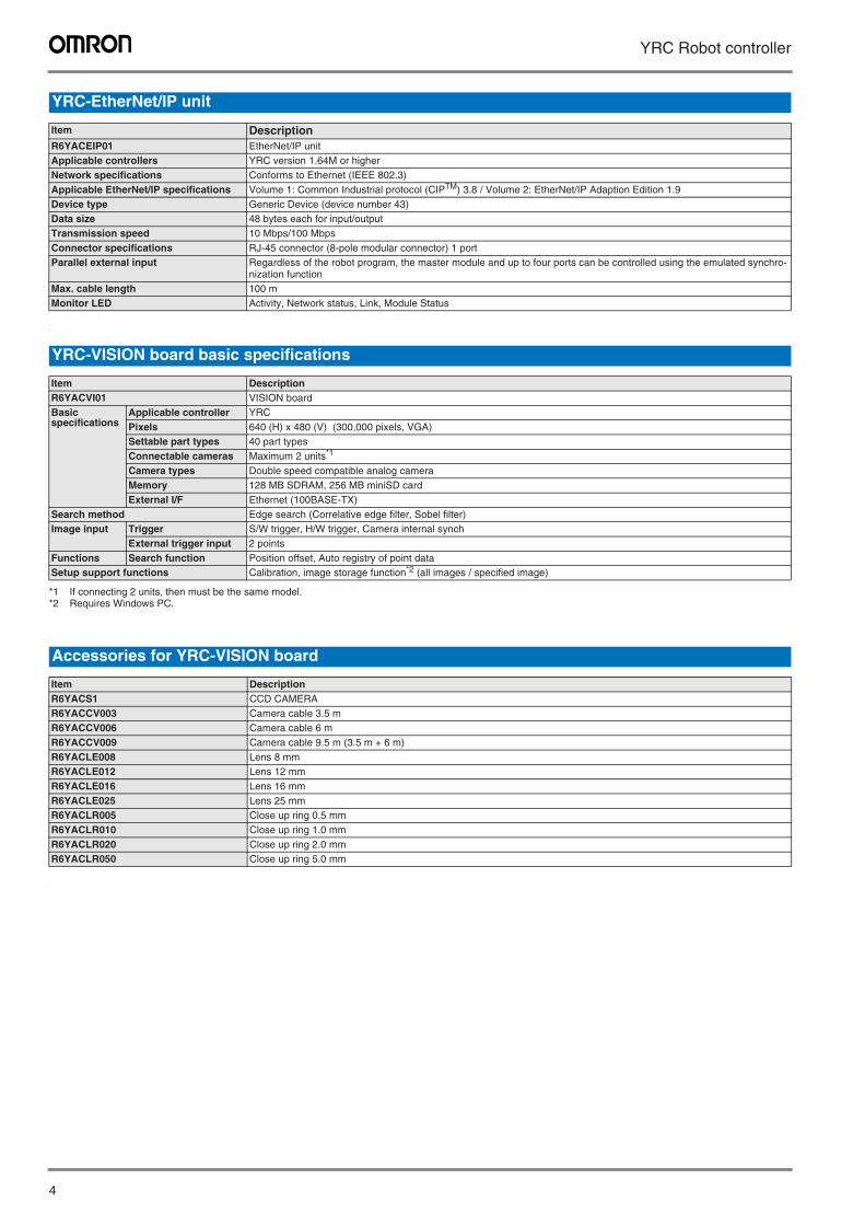
YRC-EtherNet/IP unit
Item DescriptionR6YACEIP01 EtherNet/IP unitApplicable controllers YRC version 1.64M or higherNetwork specifications Conforms to Ethernet (IEEE 802.3)Applicable EtherNet/IP specifications Volume 1: Common Industrial protocol (CIPTM) 3.8 / Volume 2: EtherNet/IP Adaption Edition 1.9Device type Generic Device (device number 43)Data size 48 bytes each for input/outputTransmission speed 10 Mbps/100 MbpsConnector specifications RJ-45 connector (8-pole modular connector) 1 portParallel external input Regardless of the robot program, the master module and up to four ports can be controlled using the emulated synchro-
nization functionMax. cable length 100 mMonitor LED Activity, Network status, Link, Module Status
YRC-VISION board basic specifications
Item DescriptionR6YACVI01 VISION boardBasicspecifications
Applicable controller YRCPixels 640 (H) x 480 (V) (300,000 pixels, VGA)Settable part types 40 part typesConnectable cameras Maximum 2 units*1
*1 If connecting 2 units, then must be the same model.
Camera types Double speed compatible analog cameraMemory 128 MB SDRAM, 256 MB miniSD cardExternal I/F Ethernet (100BASE-TX)
Search method Edge search (Correlative edge filter, Sobel filter)Image input Trigger S/W trigger, H/W trigger, Camera internal synch
External trigger input 2 pointsFunctions Search function Position offset, Auto registry of point dataSetup support functions Calibration, image storage function*2 (all images / specified image)
*2 Requires Windows PC.
Accessories for YRC-VISION board
Item DescriptionR6YACS1 CCD CAMERAR6YACCV003 Camera cable 3.5 mR6YACCV006 Camera cable 6 mR6YACCV009 Camera cable 9.5 m (3.5 m + 6 m)R6YACLE008 Lens 8 mmR6YACLE012 Lens 12 mmR6YACLE016 Lens 16 mmR6YACLE025 Lens 25 mmR6YACLR005 Close up ring 0.5 mmR6YACLR010 Close up ring 1.0 mmR6YACLR020 Close up ring 2.0 mmR6YACLR050 Close up ring 5.0 mm
SCARA robots 5
YRC Robot controller
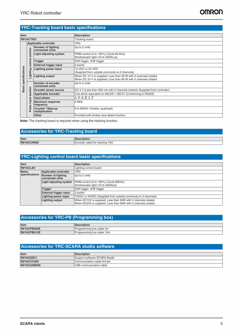
Note: The tracking board is required when using the tracking function.:
:
:
:
YRC-Tracking board basic specifications
Item DescriptionR6YACTR01 Tracking board
Bas
ic s
pec
ific
atio
ns
Applicable controller YRC
Lig
hti
ng
co
ntr
ol s
ecti
on Number of lighting
connected unitsUp to 2 units
Light adjusting system PWM control (0 to 100%) (Cycle 60 KHz)Stroboscopic light (10 to 33000 µs)
Trigger S/W trigger, H/W triggerExternal trigger input 2 pointsLighting power input 12 VDC or 24 VDC
(Supplied from outside commonly to 2 channels)Lighting output When DC 12 V is supplied: Less than 30 W with 2 channels totaled
When DC 24 V is supplied: Less than 60 W with 2 channels totaled
Pu
lse
inp
ut
sect
ion
Number of encoder connected units
Up to 2 units
Encoder power source DC 5 V (Less than 500 mA with 2 channels totaled) (Supplied from controller)Applicable encoder Line driver equivalent to 26LS31 / 26C31 (Conforming to RS422)Input phase A, A, B, B, Z, ZMaximum response frequency
2 MHz
Counter / Step-up multiplication
0 to 65535 / Double, quadruple
Other Provided with broken wire detect function
Accessories for YRC-Tracking board
Item DescriptionR6YACCR005 Encoder cable for tracking 10m
YRC-Lighting control board basic specifications
Item DescriptionR6YACLI01 Lighting control boardBasic specifications
Applicable controller YRCNumber of lightingconnected units
Up to 2 units
Light adjusting system PWM control (0 to 100%) (Cycle 60KHz)Stroboscopic light (10 to 33000us)
Trigger S/W trigger, H/W triggerExternal trigger input 2 pointsLighting power input 12VDC or 24VDC (Supplied from outside commonly to 2 channels)Lighting output When DC12V is supplied: Less than 30W with 2 channels totaled
When DC24V is supplied: Less than 60W with 2 channels totaled
Accessories for YRC-PB (Programming box)
Item DescriptionR6YACPB005E Programming box cable 5mR6YACPB012E Programming box cable 12m
Accessories for YRC-SCARA studio software
Item DescriptionR6YACSSC1 Support software SCARA StudioR6YACCC005 Communication cable 9-9 pinR6YACUSB005 USB communication cable
6
YRC Robot controller
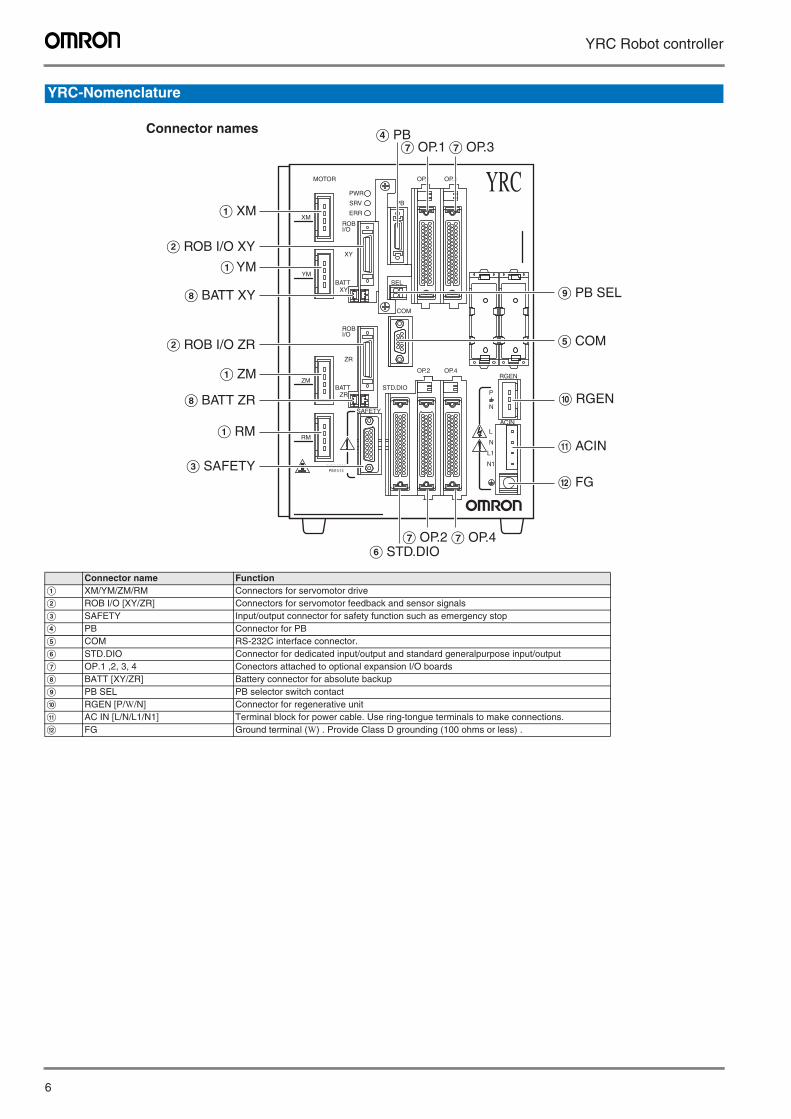
YRC-Nomenclature
Connector name FunctionA XM/YM/ZM/RM Connectors for servomotor driveB ROB I/O [XY/ZR] Connectors for servomotor feedback and sensor signalsC SAFETY Input/output connector for safety function such as emergency stopD PB Connector for PBE COM RS-232C interface connector.F STD.DIO Connector for dedicated input/output and standard generalpurpose input/outputG OP.1 ,2, 3, 4 Conectors attached to optional expansion I/O boardsH BATT [XY/ZR] Battery connector for absolute backupI PB SEL PB selector switch contactJ RGEN [P/W/N] Connector for regenerative unitK AC IN [L/N/L1/N1] Terminal block for power cable. Use ring-tongue terminals to make connections.L FG Ground terminal (W) . Provide Class D grounding (100 ohms or less) .
PB
MOTOR
XM
YM
ZM
RM
PWR
SRV
SAFETY
COM
STD.DIO
ROBI/O
ZR
OP.1 OP.3
OP.2 OP.4RGEN
ACIN
N
P
N1
L1
L
N
SEL
BATTZR
XYBATT
ROB
XY
I/O
PIN13-14EXT.E-STOP
ERR
YRC
E COM
I PB SEL
C SAFETY
A XM
A YM
A ZM
A RM
G OP.1D PB
G OP.3
G OP.2 G OP.4
J RGEN
K ACIN
L FG
B ROB I/O XY
H BATT XY
H BATT ZR
B ROB I/O ZR
F STD.DIO
Connector names
SCARA robots 7
YRC Robot controller
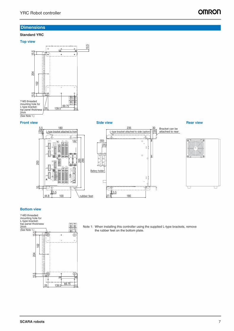
Standard YRC
Dimensions
10.5
15.5
204
102
15.5
2569.75
139.5 15.5
5.5(t2)
180
250
10
5.544.8 100
265
290
5.527.6 180
(25)(50)
235 30(20)
15.5
102
204
15.5
25 69.75139.5 15.5
RGEN
ACIN
N
P
N1
L1
L
N
YRCOP.1 OP.3MOTOR
XM
PWR
SRV PB
ROBI/O
ERR
YM
XYBATT
XY
COM
SEL
ZM
ROBI/O
ZR
BATTZR
RM
SAFETY
13 14EXT.E-STOP
STD.DIO
OP.2 OP.4
L-type bracket attached to front L-type bracket attached to side (option)
rubber feet
Battery holder
Top view
Front view
Bottom view
Side view Rear view
7-M3 threaded mounting hole for L-type bracket; top panel thickness 2mm(See Note 1.)
Bracket can be attached to rear
Note 1: When installing this controller using the supplied L-type brackets, remove the rubber feet on the bottom plate.
7-M3 threaded mounting hole for L-type bracket; top panel thickness 2mm(See Note 1.)
8
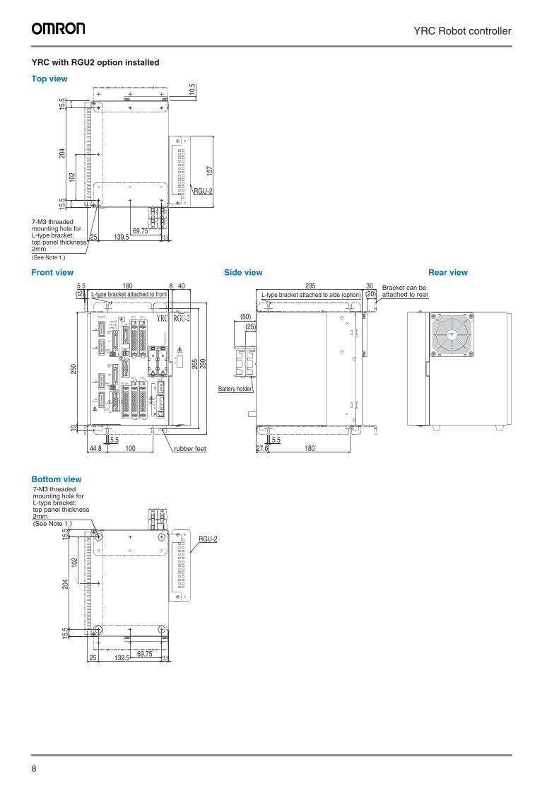
YRC Robot controller
YRC with RGU2 option installed
P
N
RGEN
10.5
15.5
204
102
15.5
2569.75
139.5 15.5
157
RGU-2
5.5(t2)
180 8 40
250
10
5.544.8 100
265
290
5.527.6 180
(25)(50)
235 30(20)
15.5
102
204
15.5
25 69.75139.5 15.5
RGU-2
RGEN
ACIN
N
P
N1
L1
L
N
YRC RGU-2OP.1 OP.3MOTOR
XM
PWR
SRV PB
ROBI/O
ERR
YM
XYBATT
XY
COM
SEL
ZM
ROBI/O
ZR
BATTZR
RM
SAFETY
13 14EXT.E-STOP
STD.DIO
OP.2 OP.4
L-type bracket attached to front
Battery holder
rubber feet
L-type bracket attached to side (option)
Top view
Front view
Bottom view
Side view Rear view
7-M3 threaded mounting hole for L-type bracket; top panel thickness 2mm(See Note 1.)
Bracket can be attached to rear
7-M3 threaded mounting hole for L-type bracket; top panel thickness 2mm(See Note 1.)
SCARA robots 9
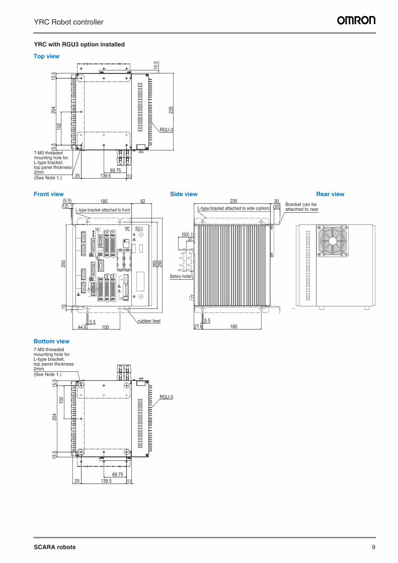
YRC Robot controller
YRC with RGU3 option installed
L-type bracket attached to front
rubber feet
L-type bracket attached to side (option)
Battery holder
RGU-3 YRC
10.5
15.5
15.5
204
102
25 139.5 15.569.75
235
62180(5.5)(t2)
265
290
250
10
44.8 1005.5
235 30(20)
(25)
27.6 1805.5
15.5
204
15.5
102
25 139.5 15.569.75
(50)
RGU-3
RGU-3
7-M3 threaded mounting hole for L-type bracket; top panel thickness 2mm(See Note 1.)
7-M3 threaded mounting hole for L-type bracket; top panel thickness 2mm(See Note 1.)
Top view
Front view
Bottom view
Side view Rear view
Bracket can be attached to rear
10
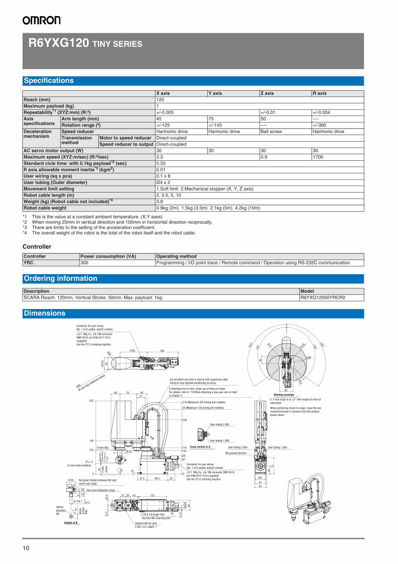
R6YXG120 TINY SERIES
Controller
Specifications
X axis Y axis Z axis R axisReach (mm) 120Maximum payload (kg) 1Repeatability*1 (XYZ:mm) (R:º)
*1 This is the value at a constant ambient temperature. (X,Y axes)
+/-0.005 +/-0.01 +/-0.004Axis specifications
Arm length (mm) 45 75 50 ----Rotation range (º) +/-125 +/-145 ---- +/-360
Deceleration mechanism
Speed reducer Harmonic drive Harmonic drive Ball screw Harmonic driveTransmission method
Motor to speed reducer Direct-coupledSpeed reducer to output Direct-coupled
AC servo motor output (W) 30 30 30 30Maximum speed (XYZ:m/sec) (R:º/sec) 3.3 0.9 1700Standard cicle time: with 0.1kg payload*2 (sec)
*2 When moving 25mm in vertical direction and 100mm in horizontal direction reciprocally.
0.33R axis allowable moment inertia*3 (kgm2)
*3 There are limits to the setting of the acceleration coefficient.
0.01User wiring (sq x pcs) 0.1 x 8User tubing (Outer diameter) Ø4 x 2Movement limit setting 1.Soft limit 2.Mechanical stopper (X, Y, Z axis)Robot cable length (m) 2, 3.5, 5, 10Weight (kg) (Robot cable not included)*4
*4 The overall weight of the robot is the total of the robot itself and the robot cable.
3.9Robot cable weight 0.9kg (2m) 1.5kg (3.5m) 2.1kg (5m) 4.2kg (10m)
Controller Power consumption (VA) Operating methodYRC 300 Programming / I/O point trace / Remote command / Operation using RS-232C communication
Ordering information
Description ModelSCARA Reach: 120mm, Vertical Stroke: 50mm, Max. payload: 1kg. R6YXG12050YRCR0
Dimensions
50
(Ø5
3)
138(120)R25
R30
(R-axis dog ro
tational radius)
75 4538
239
316 (Maximum 322 during arm rotation)
25 (Maximum 120 during arm rotation)
37
0
47+/-2
(Z-axis origin position)
105
146
322
R-axis dog
50
B
Ø 53
A
41.5 90.5
6
32
0
80
105
116
67
User tubing 2 (Ø4)
User tubing 1 (Ø4)
User tool installation range
9 0 -0
.2
Ø 10h 7 0-0.015
10
15
58 27
43
4.5 123
2-5
.5
14
R
20
2-Ø 5.5 through-hole
Use four M5 mounting bolt.
Tapped hole for user
4-M3 x 0.5, depth: 7
14
(43)
47
53
35
74
User tubing 1 (Ø4)User tubing 2 (Ø4)
M3 ground terminal
80
125°
145°
145°
125°
R120
R75
R46
46
R12
A
Working envelope
Cross section A-A
Ø 26
Details of B
22
.52
2.5
Connector for user wiring
(No. 1 to 8 usable, socket contact)
J.S.T. Mfg Co., Ltd. SM connector
SMR-8V-B, pin SYM-001T-P0.6
(supplied)
Use the YC12 crimping machine.
If attaching wire or tube, make use of these air tubes.
For details, refer to “10 When attaching a new user wire or tube”
in Chapter 3.
Do not attach any wire or tube to self-supporting cable.
Doing so may degrade positioning accuracy.
Connector for user wiring
(No. 1 to 8 usable, socket contact)
J.S.T. Mfg Co., Ltd. SM connector SMR-8V-B,
pin SYM-001T-P0.6 (supplied)
Use the YC12 crimping machine.No phase relation between flat spot
and R-axis origin
Hollow
diameter:
Ø4 Wid
thac
ross
flat
s
Ris
es 5
mm
duri
ng r
eturn
-
to-o
rigin
on
Z-a
xis
Z a
xis
stro
ke
X, Y-axis origin is at ±5° with respect to front of
robot base
When performing return-to-origin, move the axe
counterclockwise in advance from the position
shown above.
SCARA robots
11SCARA robots
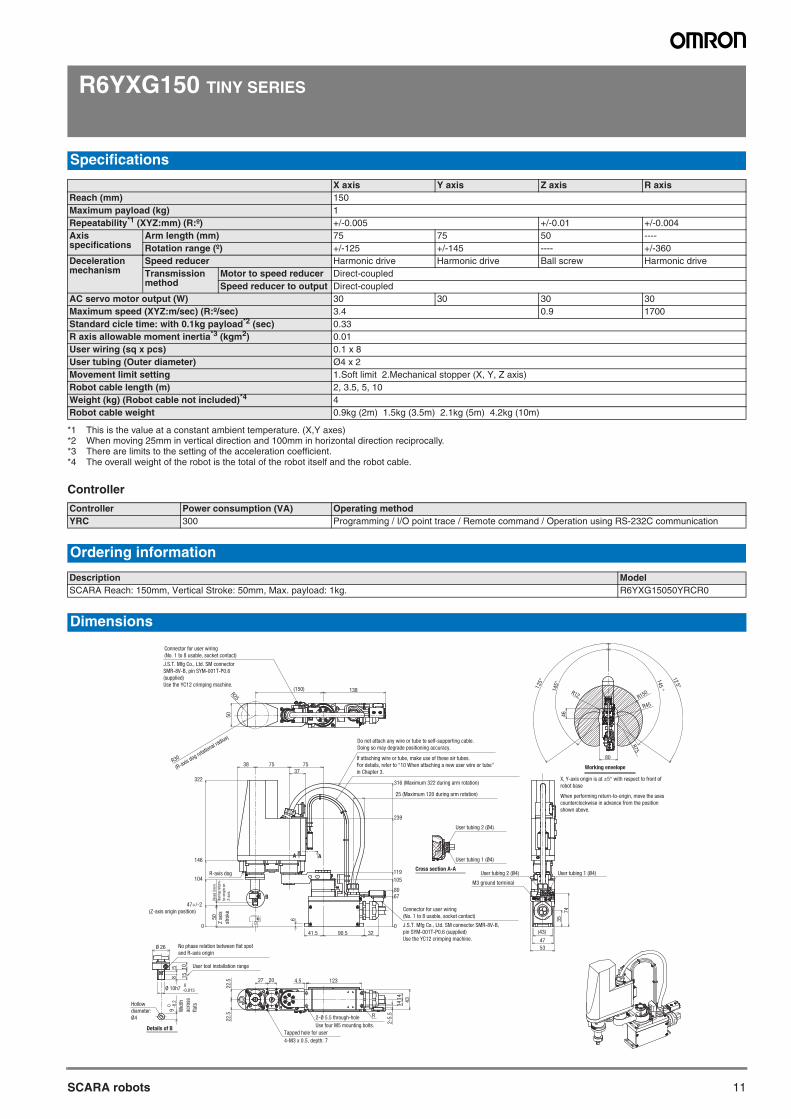
R6YXG150 TINY SERIES
Controller
Specifications
X axis Y axis Z axis R axisReach (mm) 150Maximum payload (kg) 1Repeatability*1 (XYZ:mm) (R:º)
*1 This is the value at a constant ambient temperature. (X,Y axes)
+/-0.005 +/-0.01 +/-0.004Axis specifications
Arm length (mm) 75 75 50 ----Rotation range (º) +/-125 +/-145 ---- +/-360
Deceleration mechanism
Speed reducer Harmonic drive Harmonic drive Ball screw Harmonic driveTransmission method
Motor to speed reducer Direct-coupledSpeed reducer to output Direct-coupled
AC servo motor output (W) 30 30 30 30Maximum speed (XYZ:m/sec) (R:º/sec) 3.4 0.9 1700Standard cicle time: with 0.1kg payload*2 (sec)
*2 When moving 25mm in vertical direction and 100mm in horizontal direction reciprocally.
0.33R axis allowable moment inertia*3 (kgm2)
*3 There are limits to the setting of the acceleration coefficient.
0.01User wiring (sq x pcs) 0.1 x 8User tubing (Outer diameter) Ø4 x 2Movement limit setting 1.Soft limit 2.Mechanical stopper (X, Y, Z axis)Robot cable length (m) 2, 3.5, 5, 10Weight (kg) (Robot cable not included)*4
*4 The overall weight of the robot is the total of the robot itself and the robot cable.
4Robot cable weight 0.9kg (2m) 1.5kg (3.5m) 2.1kg (5m) 4.2kg (10m)
Controller Power consumption (VA) Operating methodYRC 300 Programming / I/O point trace / Remote command / Operation using RS-232C communication
Ordering information
Description ModelSCARA Reach: 150mm, Vertical Stroke: 50mm, Max. payload: 1kg. R6YXG15050YRCR0
Dimensions
138R25
(150)
50
R30
(R-axis dog ro
tational radius)
7538 75
37
239
316 (Maximum 322 during arm rotation)
25 (Maximum 120 during arm rotation)
0
47+/-2
(Z-axis origin position)
322
R-axis dog
50
104
146
B
A
41.5 90.5
6
32
0
80
105
67
119
Details of B
User tool installation range
9 0 -0
.2
Ø 10h7 0-0.015
Ø 26
10
15
58
27
43
4.5 123
2-5
.5
14
14
R
20
2-Ø 5.5 through-hole
Use four M5 mounting bolts.
Tapped hole for user
4-M3 x 0.5, depth: 7
Cross section A-A
46
R150
145°
125
° 145°
125°
Working envelope
80
R12
R75
R45
(43)
47
53
35
74
User tubing 1 (Ø4)User tubing 2 (Ø4)
M3 ground terminal
A
User tubing 2 (Ø4)
User tubing 1 (Ø4)
22.5
22.5
Connector for user wiring
(No. 1 to 8 usable, socket contact)
J.S.T. Mfg Co., Ltd. SM connector
SMR-8V-B, pin SYM-001T-P0.6
(supplied)
Use the YC12 crimping machine.
If attaching wire or tube, make use of these air tubes.
For details, refer to “10 When attaching a new user wire or tube”
in Chapter 3.
Do not attach any wire or tube to self-supporting cable.
Doing so may degrade positioning accuracy.
Connector for user wiring
(No. 1 to 8 usable, socket contact)
J.S.T. Mfg Co., Ltd. SM connector SMR-8V-B,
pin SYM-001T-P0.6 (supplied)
Use the YC12 crimping machine.
No phase relation between flat spot
and R-axis origin
Hollow
diameter:
Ø4
X, Y-axis origin is at ±5° with respect to front of
robot base
When performing return-to-origin, move the axes
counterclockwise in advance from the position
shown above.
Wid
th
acro
ss
flat
s
Z a
xis
stro
ke
Ris
es 5
mm
duri
ng r
eturn
-
to-o
rigin
on
Z-a
xis.
SCARA robots
12
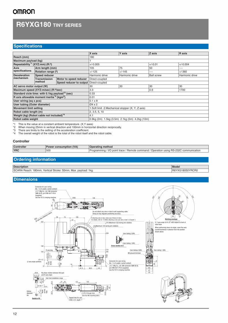
R6YXG180 TINY SERIES
Controller
Specifications
X axis Y axis Z axis R axisReach (mm) 180Maximum payload (kg) 1Repeatability*1 (XYZ:mm) (R:º)
*1 This is the value at a constant ambient temperature. (X,Y axes)
+/-0.005 +/-0.01 +/-0.004Axis specifications
Arm length (mm) 105 75 50 ----Rotation range (º) +/-125 +/-145 ---- +/-360
Deceleration mechanism
Speed reducer Harmonic drive Harmonic drive Ball screw Harmonic driveTransmission method
Motor to speed reducer Direct-coupledSpeed reducer to output Direct-coupled
AC servo motor output (W) 30 30 30 30Maximum speed (XYZ:m/sec) (R:º/sec) 3.3 0.9 1700Standard cicle time: with 0.1kg payload*2 (sec)
*2 When moving 25mm in vertical direction and 100mm in horizontal direction reciprocally.
0.33R axis allowable moment inertia*3 (kgm2)
*3 There are limits to the setting of the acceleration coefficient.
0.01User wiring (sq x pcs) 0.1 x 8User tubing (Outer diameter) Ø4 x 2Movement limit setting 1.Soft limit 2.Mechanical stopper (X, Y, Z axis)Robot cable length (m) 2, 3.5, 5, 10Weight (kg) (Robot cable not included)*4
*4 The overall weight of the robot is the total of the robot itself and the robot cable.
4.1Robot cable weight 0.9kg (2m) 1.5kg (3.5m) 2.1kg (5m) 4.2kg (10m)
Controller Power consumption (VA) Operating methodYRC 500 Programming / I/O point trace / Remote command / Operation using RS-232C communication
Ordering information
Description ModelSCARA Reach: 180mm, Vertical Stroke: 50mm, Max. payload: 1kg. R6YXG18050YRCR0
Dimensions
B
50
138R25
R30
(R-axis dog ro
tational radius)
(180)
38
47+/-2
(Z-axis origin position)
322
R-axis dog
50
104
146
75 105
37
41.5 90.5
0
6
32
0
80
105
239
316 (Maximum 322 during arm rotation)
67
119
10 (Maximum 120 during arm rotation)
85
15
10
Ø 26
Ø 10h 7 0-0.015
9 0 -0
.2
User tool installation range
Details of B
27
43
4.5 123
2-5
.5
14
14
R
20
2-Ø 5.5 through-hole
(Use four M5 mounting bolts.)
Tapped hole for user
4-M3 x 0.5, depth: 7
Cross section A-A
User tubing 2 (Ø4)
M3 ground terminal
User tubing 2 (Ø4)
User tubing 1 (Ø4)
(43)
47
53
35
74
User tubing 1 (Ø4)
Working envelope
80
145°
125°
125°
145°R1
80
R61
R75
AA
22
.52
2.5
If attaching wire or tube, make use of these air tubes.
For details, refer to “10 When attaching a new user wire or tube” in Chapter 3.
Do not attach any wire or tube to self-supporting cable.
Doing so may degrade positioning accuracy.
Connector for user wiring
(No. 1 to 8 usable, socket contact)
J.S.T. Mfg Co., Ltd. SM connector
SMR-8V-B, pin SYM-001T-P0.6
(supplied)
Use the YC12 crimping machine.
Connector for user wiring
(No. 1 to 8 usable, socket contact)
J.S.T. Mfg Co., Ltd. SM connector SMR-8V-B,
pin SYM-001T-P0.6 (supplied)
Use the YC12 crimping machine.
No phase relation between flat spot
and R-axis origin
Hollow
diameter:
Ø4
X, Y-axis origin is at ±5° with respect to front of
robot base
When performing return-to-origin, move the axes
counterclockwise in advance from the position
shown above.
Ris
es 5
mm
duri
ng r
eturn
-
to-o
rigin
on
Z-a
xis.
Z a
xis
stro
ke
Wid
th
acro
ss
flat
s
SCARA robots
13SCARA robots
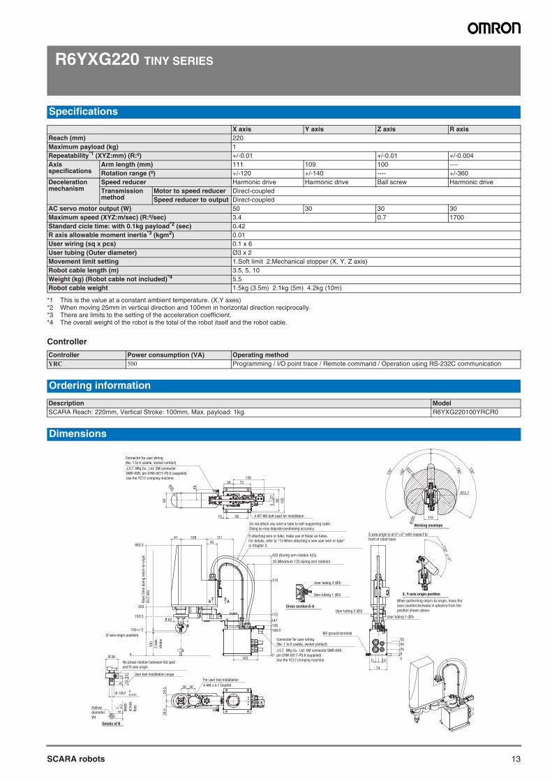
R6YXG220 TINY SERIES
Controller
Specifications
X axis Y axis Z axis R axisReach (mm) 220Maximum payload (kg) 1Repeatability*1 (XYZ:mm) (R:º)
*1 This is the value at a constant ambient temperature. (X,Y axes)
+/-0.01 +/-0.01 +/-0.004Axis specifications
Arm length (mm) 111 109 100 ----Rotation range (º) +/-120 +/-140 ---- +/-360
Deceleration mechanism
Speed reducer Harmonic drive Harmonic drive Ball screw Harmonic driveTransmission method
Motor to speed reducer Direct-coupledSpeed reducer to output Direct-coupled
AC servo motor output (W) 50 30 30 30Maximum speed (XYZ:m/sec) (R:º/sec) 3.4 0.7 1700Standard cicle time: with 0.1kg payload*2 (sec)
*2 When moving 25mm in vertical direction and 100mm in horizontal direction reciprocally.
0.42R axis allowable moment inertia*3 (kgm2)
*3 There are limits to the setting of the acceleration coefficient.
0.01User wiring (sq x pcs) 0.1 x 6User tubing (Outer diameter) Ø3 x 2Movement limit setting 1.Soft limit 2.Mechanical stopper (X, Y, Z axis)Robot cable length (m) 3.5, 5, 10Weight (kg) (Robot cable not included)*4
*4 The overall weight of the robot is the total of the robot itself and the robot cable.
5.5Robot cable weight 1.5kg (3.5m) 2.1kg (5m) 4.2kg (10m)
Controller Power consumption (VA) Operating methodYRC 500 Programming / I/O point trace / Remote command / Operation using RS-232C communication
Ordering information
Description ModelSCARA Reach: 220mm, Vertical Stroke: 100mm, Max. payload: 1kg. R6YXG220100YRCR0
Dimensions
B
60
39 73
90
10
5
130
27
5
R30
10 92 4-Ø7 M6 bolt used for installation
44
Ø 62
203
463.5
163.5
0
100+/-2
(Z-axis origin position)
45
11110941
100
109.5
173
126
147
315
30 (Maximum 120 during arm rotation)
420 (During arm rotation 425)
User tubing 1 (Ø3)
User tubing 2 (Ø3)
Connector for user wiring
(No. 1 to 6 usable, socket contact)
J.S.T. Mfg Co., Ltd. SM connector SMR-6VB,
pin SYM-001T-P0.6 (supplied)
Use the YC12 crimping machine.
0103
74
M3 ground terminal
11 15 0
8
25
5055
User tubing 1 (Ø3)
User tubing 2 (Ø3)
Working envelope
X, Y-axis origin position
140°
120°
R10
9
R220
R75.7
133°+
/-5°
119
120°
140°
Details of B
85
15
10
Ø 26
Ø 10h7 0-0.015
9 0 -0
.2
User tool installation range
30
For user tool installation
4-M4 x 0.7 Depth6
24.5
24.5
30
A ACross section A-A
If attaching wire or tube, make use of these air tubes.
For details, refer to “10 When attaching a new user wire or tube”
in Chapter 3.
Do not attach any wire or tube to self-supporting cable.
Doing so may degrade positioning accuracy.
Connector for user wiring
(No. 1 to 6 usable, socket contact)
J.S.T. Mfg Co., Ltd. SM connector
SMR-6VB, pin SYM-001T-P0.6 (supplied)
Use the YC12 crimping machine.
No phase relation between flat spot
and R-axis origin
Hollow
diameter:
Ø4
When performing return-to-origin, move the
axes counterclockwise in advance from the
position shown above.
X-axis origin is at 0°±5° with respect to
front of robot base
Wid
th
acro
ss
flat
s
Z a
xis
stro
ke
Ris
es 5
mm
duri
ng r
eturn
-to-
orig
in
on Z
-axi
s.
SCARA robots
14
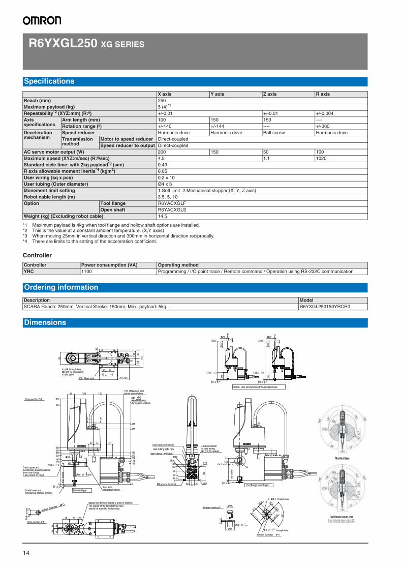
R6YXGL250 XG SERIES
Controller
Specifications
X axis Y axis Z axis R axisReach (mm) 250Maximum payload (kg) 5 (4)*1
*1 Maximum payload is 4kg when tool flange and hollow shaft options are installed.
Repeatability*2 (XYZ:mm) (R:º)
*2 This is the value at a constant ambient temperature. (X,Y axes)
+/-0.01 +/-0.01 +/-0.004Axis specifications
Arm length (mm) 100 150 150 ----Rotation range (º) +/-140 +/-144 ---- +/-360
Deceleration mechanism
Speed reducer Harmonic drive Harmonic drive Ball screw Harmonic driveTransmission method
Motor to speed reducer Direct-coupledSpeed reducer to output Direct-coupled
AC servo motor output (W) 200 150 50 100Maximum speed (XYZ:m/sec) (R:º/sec) 4.5 1.1 1020Standard cicle time: with 2kg payload*3 (sec)
*3 When moving 25mm in vertical direction and 300mm in horizontal direction reciprocally.
0.49R axis allowable moment inertia*4 (kgm2)
*4 There are limits to the setting of the acceleration coefficient.
0.05User wiring (sq x pcs) 0.2 x 10User tubing (Outer diameter) Ø4 x 3Movement limit setting 1.Soft limit 2.Mechanical stopper (X, Y, Z axis)Robot cable length (m) 3.5, 5, 10Option Tool flange R6YACXGLF
Open shaft R6YACXGLSWeight (kg) (Excluding robot cable) 14.5
Controller Power consumption (VA) Operating methodYRC 1100 Programming / I/O point trace / Remote command / Operation using RS-232C communication
Ordering information
Description ModelSCARA Reach: 250mm, Vertical Stroke: 150mm, Max. payload: 5kg. R6YXGL250150YRCR0
Dimensions
93
138 (Base size)
104 60
60
140
4 bolts usedM8 bolt for installation,4- 9 through-hole
(19~90)
90
30 62
50 88
Hollow diameter 11
flat
15W
idth
acr
oss
Cross section A-A
50 70 20
101039
39
The weight of the tool attached here should be added to the tip mass.
Tapped hole for user wiring 6-M3X0.5 Depth 6
1230
35
129 (Maximum 280 during arm rotation)
47
16 h7 -0.0180
0
202222246
640(Maximum 660during arm rotation)
167174
100150
44
0
138.5 +/-2183187
230235264283
614
661
150
str
oke
11.5
428
468
42 57
56
AA
B B
User tool installation rangeZ-axis lower end
mechanical stopper position
Z-axis upper endmechanical stopper position4mm rise duringZ-axis return-to-origin
Standard type
11
Cross section B-B
113
20 200
33
76
12
112129
D-sub connectorfor user wiring(No.1 to 10 usable)
User tubing 1(Φ4 black)
User tubing 2(Φ4 red)
User tubing 3(Φ4 blue)
M4 ground terminal
XYP
ZRP
XYM
ZRM
35
30 h7 - 0.0210
55
24
Detailed drawing C
90°
22.6
22.6
22.60.02 7
0.02
22.6
22.6
4- 4.5 through-hole
4 H7 0+0.012
through-hole
Hollow diameter 11
Standard type
X-axis mechanical stopper position:142°Y-axis mechanical stopper position:146°
Tool flange mount type
5
150
150
27
0
138.5 +/-2
780.5
011.5
D
Option: User wiring/tubing through spline type
150
150 5
27
0
134.5 +/-2
780.5
015.5
D
150
str
oke
0
134.5 +/-2149
181
015.5
C
Tool flange mount type
SCARA robots

15SCARA robots
R6YXGL350 XG SERIES
Controller
Specifications
X axis Y axis Z axis R axisReach (mm) 350Maximum payload (kg) 5 (4)*1
*1 Maximum payload is 4kg when tool flange and hollow shaft options are installed.
Repeatability*2 (XYZ:mm) (R:º)
*2 This is the value at a constant ambient temperature. (X,Y axes)
+/-0.01 +/-0.01 +/-0.004Axis specifications
Arm length (mm) 200 150 150 ----Rotation range (º) +/-140 +/-144 ---- +/-360
Deceleration mechanism
Speed reducer Harmonic drive Harmonic drive Ball screw Harmonic driveTransmission method
Motor to speed reducer Direct-coupledSpeed reducer to output Direct-coupled
AC servo motor output (W) 200 150 50 100Maximum speed (XYZ:m/sec) (R:º/sec) 5.6 1.1 1020Standard cicle time: with 2kg payload*3 (sec)
*3 When moving 25mm in vertical direction and 300mm in horizontal direction reciprocally.
0.49R axis allowable moment inertia*4 (kgm2)
*4 There are limits to the setting of the acceleration coefficient.
0.05User wiring (sq x pcs) 0.2 x 10User tubing (Outer diameter) Ø4 x 3Movement limit setting 1.Soft limit 2.Mechanical stopper (X, Y, Z axis)Robot cable length (m) 3.5, 5, 10Option Tool flange R6YACXGLF
Open shaft R6YACXGLSWeight (kg) (Excluding robot cable) 15
Controller Power consumption (VA) Operating methodYRC 1100 Programming / I/O point trace / Remote command / Operation using RS-232C communication
Ordering information
Description ModelSCARA Reach: 350mm, Vertical Stroke: 150mm, Max. payload: 5kg. R6YXGL350150YRCR0
Dimensions
Hollow diameter 11
flat
15W
idth
acr
oss
Cross section A-A
150
stro
ke
0
134.5 +/-2149
181
015.5
C
Tool flange mount type
35
30 h7 - 0.0210
55
24
Detailed drawing C
-through-hole4 4.5
90°
22.6
22.6
22.60.02 7
0.02
22.6
22.6
4 H7 0+0.012
through-hole
diameter 11Hollow
5
150
150
27
0
138.5 +/-2
780.5
011.5
Option: User wiring/tubing through spline type
150
150 5
27
0
134.5 +/-2
780.5
015.5
D
Standard type
X-axis mechanical stopper position:142°Y-axis mechanical stopper position:146°
Tool flange mount type
93
138 (Base size)
104 60
60
140
90
4 bolts usedM8 bolt for installation,4- 9 through-hole
(19~90)
30 62
50 88
50 70 20
101039
39
Tapped hole for user wiring 6-M 3x0.5 Depth 6The weight of the tool attached here should be added to the tip mass.
1230
35
129 (Maximum 330 during arm rotation)
47
16 h7 -0.0180
0
202222246
620(Maximum 660during arm rotation)
167174
200150
44
0
138.5 +/-2183187
230235264283
614
661
150
str
oke
11.5
56
428
468
42 57
AA
B B
User tool installation range
Z-axis lower endmechanical stopper position
Z-axis upper endmechanical stopper position4mm rise duringZ-axis return-to-origin
Standard type
Cross section B-B
113
20 200
1233
76
112129
M4 ground terminal
D-sub connectorfor user wiring(No.1 to 10 usable)
XYP
ZRP
XYM
ZRM
User tubing 1(Φ4 black)
User tubing 3(Φ4 blue)
User tubing 2(Φ4 red)
SCARA robots
16
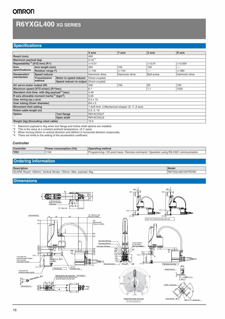
R6YXGL400 XG SERIES
Controller
Specifications
X axis Y axis Z axis R axisReach (mm) 400Maximum payload (kg) 5 (4)*1
*1 Maximum payload is 4kg when tool flange and hollow shaft options are installed.
Repeatability*2 (XYZ:mm) (R:º)
*2 This is the value at a constant ambient temperature. (X,Y axes)
+/-0.01 +/-0.01 +/-0.004Axis specifications
Arm length (mm) 250 150 150 ----Rotation range (º) +/-140 +/-144 ---- +/-360
Deceleration mechanism
Speed reducer Harmonic drive Harmonic drive Ball screw Harmonic driveTransmission method
Motor to speed reducer Direct-coupledSpeed reducer to output Direct-coupled
AC servo motor output (W) 200 150 50 100Maximum speed (XYZ:m/sec) (R:º/sec) 6.1 1.1 1020Standard cicle time: with 2kg payload*3 (sec)
*3 When moving 25mm in vertical direction and 300mm in horizontal direction reciprocally.
0.49R axis allowable moment inertia*4 (kgm2)
*4 There are limits to the setting of the acceleration coefficient.
0.05User wiring (sq x pcs) 0.2 x 10User tubing (Outer diameter) Ø4 x 3Movement limit setting 1.Soft limit 2.Mechanical stopper (X, Y, Z axis)Robot cable length (m) 3.5, 5, 10Option Tool flange R6YACXGLF
Open shaft R6YACXGLSWeight (kg) (Excluding robot cable) 15.5
Controller Power consumption (VA) Operating methodYRC 1100 Programming / I/O point trace / Remote command / Operation using RS-232C communication
Ordering information
Description ModelSCARA Reach: 400mm, Vertical Stroke: 150mm, Max. payload: 5kg. R6YXGL400150YRCR0
Dimensions
Hollow diameter 11
flat
15W
idth
acr
oss
Cross section A-A
X-axis mechanical stopper position:142°Y-axis mechanical stopper position:146°
Standard/Tool flange mount type
93
138 (Base size)
104 60
60
140
90
4 bolts usedM8 bolt for installation,4- 9 through-hole
(19~90)
30 62
50 88
50 70 20
101039
39
Tapped hole for user wiring 6-M 3x0.5 Depth 6The weight of the tool attached here should be added to the tip mass.
0
202222246
620(Maximum 660
167174
428
468
1230
129 (Maximum 380during arm rotation)
47
16 h7 -0.0180
35
during arm rotation)
250150
44
0
138.5 +/-2
183187
230235264283
614
661
11.5
56
57
150
str
oke
42
AA
B B
User tool installation range
Z-axis lower endmechanical stopper position
Z-axis upper endmechanical stopper position4mm rise duringZ-axis return-to-origin
Standard type
Cross section B-B
113
20 200
123376
112129
D-sub connectorfor user wiring(No.1 to 10 usable)
User tubing 2(Φ4 red)
User tubing 3(Φ4 blue)
User tubing 1(Φ4 black)
M4 ground terminal
XYP
ZRP
ZRM
XYM
150
stro
ke
0
134.5 +/-2149181
015.5
C
Tool flange mount type35
30 h7 - 0.0210
55
24
Detailed drawing C
90°
22.6
22.6
22.60.02 7
0.02
22.6
22.6
4- 4.5 through-hole
4 H7 0+0.012
through-hole Hollow diameter 11
5
150
150
27
0
138.5 +/-2
780.5
011.5
D
Option: User wiring/tubing through spline type
150
150 5
27
0
134.5 +/-2
780.5
015.5
D
SCARA robots
17SCARA robots
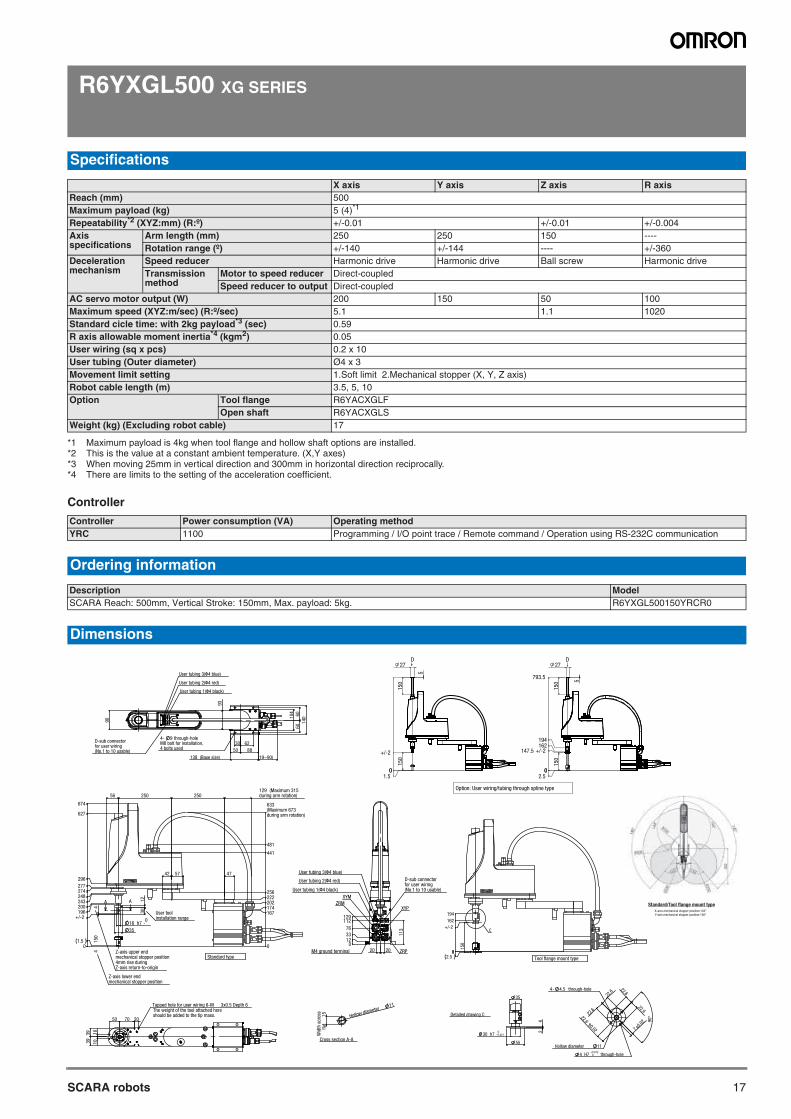
R6YXGL500 XG SERIES
Controller
Specifications
X axis Y axis Z axis R axisReach (mm) 500Maximum payload (kg) 5 (4)*1
*1 Maximum payload is 4kg when tool flange and hollow shaft options are installed.
Repeatability*2 (XYZ:mm) (R:º)
*2 This is the value at a constant ambient temperature. (X,Y axes)
+/-0.01 +/-0.01 +/-0.004Axis specifications
Arm length (mm) 250 250 150 ----Rotation range (º) +/-140 +/-144 ---- +/-360
Deceleration mechanism
Speed reducer Harmonic drive Harmonic drive Ball screw Harmonic driveTransmission method
Motor to speed reducer Direct-coupledSpeed reducer to output Direct-coupled
AC servo motor output (W) 200 150 50 100Maximum speed (XYZ:m/sec) (R:º/sec) 5.1 1.1 1020Standard cicle time: with 2kg payload*3 (sec)
*3 When moving 25mm in vertical direction and 300mm in horizontal direction reciprocally.
0.59R axis allowable moment inertia*4 (kgm2)
*4 There are limits to the setting of the acceleration coefficient.
0.05User wiring (sq x pcs) 0.2 x 10User tubing (Outer diameter) Ø4 x 3Movement limit setting 1.Soft limit 2.Mechanical stopper (X, Y, Z axis)Robot cable length (m) 3.5, 5, 10Option Tool flange R6YACXGLF
Open shaft R6YACXGLSWeight (kg) (Excluding robot cable) 17
Controller Power consumption (VA) Operating methodYRC 1100 Programming / I/O point trace / Remote command / Operation using RS-232C communication
Ordering information
Description ModelSCARA Reach: 500mm, Vertical Stroke: 150mm, Max. payload: 5kg. R6YXGL500150YRCR0
Dimensions
Hollow diameter 11
flat
15W
idth
acr
oss
Cross section A-A
X-axis mechanical stopper position:142°Y-axis mechanical stopper position:146°
Standard/Tool flange mount type
93
138 (Base size)
104
6060
140
4 bolts usedM8 bolt for installation,4- 9 through-hole
(19~90)
90
30 62
50 88
User tubing 1(Φ4 black)
User tubing 2(Φ4 red)
User tubing 3(Φ4 blue)
D-sub connector for user wiring (No.1 to 10 usable)
1230
129 (Maximum 315during arm rotation)
47
16 h7 -0
250 250
5742
35
56
0
202222256
633(Maximum 673during arm rotation)
167174
44
0
+/-2196200243248
150
1.5
481
441
274277
627
674
296
AA
Z-axis lower endmechanical stopper position
Z-axis upper endmechanical stopper position4mm rise duringZ-axis return-to-origin
Standard type
User tool installation range
50 70 20
1010
3939
Tapped hole for user wiring 6-M 3x0.5 Depth 6The weight of the tool attached here should be added to the tip mass.
113
20 200
33
76
12
112129
D-sub connectorfor user wiring(No.1 to 10 usable)User tubing 1(Φ4 black)
User tubing 2(Φ4 red)
User tubing 3(Φ4 blue)
M4 ground terminal
XYP
ZRP
XYM
ZRM
150
0
+/-2
162
194
02.5
C
Tool flange mount type
35
30 h7 - 0.0210
55
24
Detailed drawing C
90°
22.6
22.6
22.60.02 7
0.02
22.6
22.6
4- 4.5 through-hole
4 H7 0+0.012
through-hole
Hollow diameter 11
5
150
150
27
0
+/-2
01.5
D
Option: User wiring/tubing through spline type
150
150 5
27
0
147.5 +/-2
793.5
02.5
162194
D
SCARA robots
18
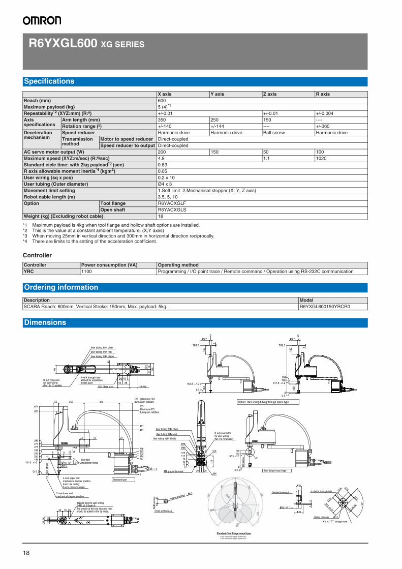
R6YXGL600 XG SERIES
Controller
Specifications
X axis Y axis Z axis R axisReach (mm) 600Maximum payload (kg) 5 (4)*1
*1 Maximum payload is 4kg when tool flange and hollow shaft options are installed.
Repeatability*2 (XYZ:mm) (R:º)
*2 This is the value at a constant ambient temperature. (X,Y axes)
+/-0.01 +/-0.01 +/-0.004Axis specifications
Arm length (mm) 350 250 150 ----Rotation range (º) +/-140 +/-144 ---- +/-360
Deceleration mechanism
Speed reducer Harmonic drive Harmonic drive Ball screw Harmonic driveTransmission method
Motor to speed reducer Direct-coupledSpeed reducer to output Direct-coupled
AC servo motor output (W) 200 150 50 100Maximum speed (XYZ:m/sec) (R:º/sec) 4.9 1.1 1020Standard cicle time: with 2kg payload*3 (sec)
*3 When moving 25mm in vertical direction and 300mm in horizontal direction reciprocally.
0.63R axis allowable moment inertia*4 (kgm2)
*4 There are limits to the setting of the acceleration coefficient.
0.05User wiring (sq x pcs) 0.2 x 10User tubing (Outer diameter) Ø4 x 3Movement limit setting 1.Soft limit 2.Mechanical stopper (X, Y, Z axis)Robot cable length (m) 3.5, 5, 10Option Tool flange R6YACXGLF
Open shaft R6YACXGLSWeight (kg) (Excluding robot cable) 18
Controller Power consumption (VA) Operating methodYRC 1100 Programming / I/O point trace / Remote command / Operation using RS-232C communication
Ordering information
Description ModelSCARA Reach: 600mm, Vertical Stroke: 150mm, Max. payload: 5kg. R6YXGL600150YRCR0
Dimensions
Hollow diameter 11
flat
15W
idth
acr
oss
Cross section A-A
93
138 (Base size)
104
6060
140
4 bolts usedM8 bolt for installation,4- 9 through-hole
(19~90)
90
30 62
50 88
User tubing 1(Φ4 black)
User tubing 2(Φ4 red)
User tubing 3(Φ4 blue)
D-sub connector for user wiring (No.1 to 10 usable)
1230
129 (Maximum 355during arm rotation)
47
16 h7 -0.0180
250 350
5742
35
56
0
202222256
633(Maximum 673during arm rotation)
167174
44
0
151.5 +/-2196200243
248
150
str
oke
1.5
481
441
274277
627
674
296
AA
Z-axis lower endmechanical stopper position
Z-axis upper endmechanical stopper position4mm rise duringZ-axis return-to-origin
Standard type
User tool installation range
50 70 20
1010
3939
6-M3 x0.5 Depth 6Tapped hole for user wiring
The weight of the tool attached here should be added to the tip mass.
113
20 20
0
3376
12
112129
D-sub connectorfor user wiring(No.1 to 10 usable)
User tubing 2(Φ4 red)
User tubing 3(Φ4 blue)
M4 ground terminal
XYP
ZRP
XYM
ZRM
User tubing 1(Φ4 black)
X-axis mechanical stopper position:142°Y-axis mechanical stopper position:146°
Standard/Tool flange mount type
150
stro
ke
0
147.5 +/-2162194
0
2.5
C
Tool flange mount type
35
30 h7 - 0.0210
55
24
Detailed drawing C
90°
22.6
22.6
22.60.02 7
0.02
22.6
22.6
4- 4.5 through-hole
4 H7 0+0.012
through-hole
Hollow diameter 11
5
150
150
27
0
151.5 +/-2
793.5
01.5
D
Option: User wiring/tubing through spline type
150
150 5
27
0
147.5 +/-2
793.5
02.5
162194
D
SCARA robots

19SCARA robots
R6YXG500 XG SERIES
Controller
Specifications
X axis Y axis Z axis R axisReach (mm) 500Maximum payload (kg) 10Repeatability*1 (XYZ:mm) (R:º)
*1 This is the value at a constant ambient temperature. (X,Y axes)
+/-0.01 +/-0.01 +/-0.004Axis specifications
Arm length (mm) 200 300 200 300 ----Rotation range (º) +/-130 +/-145 ---- +/-360
Deceleration mechanism
Speed reducer Harmonic drive Harmonic drive Ball screw Harmonic driveTransmission method
Motor to speed reducer Direct-coupledSpeed reducer to output Direct-coupled
AC servo motor output (W) 400 200 200 200Maximum speed (XYZ:m/sec) (R:º/sec) 7.6 2.3 1.7 1700Standard cicle time: with 2kg payload*2 (sec)
*2 When moving 25mm in vertical direction and 300mm in horizontal direction reciprocally.
0.45R axis allowable moment inertia*3 (kgm2)
*3 There are limits to the setting of the acceleration coefficient.
0.30User wiring (sq x pcs) 0.2 x 20User tubing (Outer diameter) Ø6 x 3Movement limit setting 1.Soft limit 2.Mechanical stopper (X, Y, Z axis)Robot cable length (m) 3.5, 5, 10Weight (kg) (Excluding robot cable) 30
Controller Power consumption (VA) Operating methodYRC 1700 Programming / I/O point trace / Remote command / Operation using RS-232C communication
Ordering information
Description ModelSCARA Reach: 500mm, Vertical Stroke: 200mm, Max. payload: 10kg. R6YXG500200YRCR3SCARA Reach: 500mm, Vertical Stroke: 300mm, Max. payload: 10kg. R6YXG500300YRCR3
Dimensions
Cross section A-A
R6YXG500200
Model Name
300mm
200mm
Z axis stroke
R6YXG500300
Wid
th a
cros
s fla
t 19
Hollow diameter Ø14
R6YXG500 Z200mm R6YXG500 Z300mm
AA
D-sub connector for user wiring
(No.1 to 20 usable)
89
10
10
71
81
11354
140
120
20030071
120
0
158.5
187
259
373
652
0
137.6+/-2
204
253
283
351
675
775
213
242
4-Ø11M10 bolt for installation,4bolt used
Ø20h7 0-0.021
100
User tubing 1 (Ø6 black)
User tubing 2 (Ø6 red)
User tubing 3 (Ø6 blue)
3210
40
40
Ø50
40
14
40
85
XYP105
50
ZRP
ZRM 37
15
0
125
50
80
User tubing 1(Ø6 black)
User tubing 2(Ø6 red)
M4 ground terminal
User tubing 3(Ø6 blue)
115
XYM
0
20 20
178
79
79
150
200 (Base size) 19~89
Z
200mm stroke
Z
300mm stroke
8m
m r
ise
duri
ng
Z-a
xis
retu
rn-t
o-or
igin
Z-axis lower end
mechanical stopper position
M16X2 Depth 20 (Bottom of spline)
300 Z
-Axi
s st
roke
Working envelope of left-handed system
X-axis mechanical stopper position:132°Y-axis mechanical stopper position:147°
Working envelope of right-handed system
130°
130°
145°
260
50
144
165
145°
130°
130°
165
260
50
144
R300
R178
R25
R300
R500
114°
R300
R25
R500
R300
R178
114°
User tool
installation range
(Maximum 660
during arm rotation)
Flat surface has no phase relation to
R-axis origin
4-M4X0.7 through-hole for tool attachment
Four M4X10L binding screws are supplied.
Do not screw the screws in deeper than 10mm
from bottom surface of arm.
200 Z
-Axi
s st
roke
D-sub connector for user wiring
(No.1 to 20 usable)
SCARA robots
20
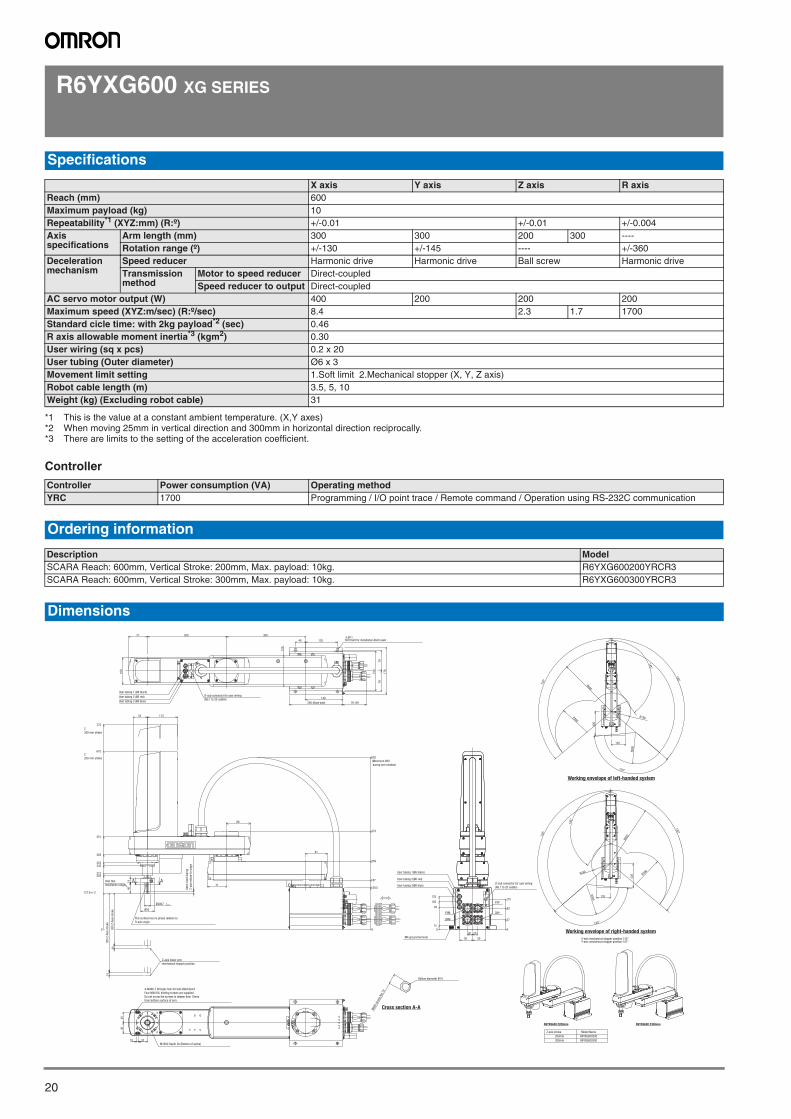
R6YXG600 XG SERIES
Controller
Specifications
X axis Y axis Z axis R axisReach (mm) 600Maximum payload (kg) 10Repeatability*1 (XYZ:mm) (R:º)
*1 This is the value at a constant ambient temperature. (X,Y axes)
+/-0.01 +/-0.01 +/-0.004Axis specifications
Arm length (mm) 300 300 200 300 ----Rotation range (º) +/-130 +/-145 ---- +/-360
Deceleration mechanism
Speed reducer Harmonic drive Harmonic drive Ball screw Harmonic driveTransmission method
Motor to speed reducer Direct-coupledSpeed reducer to output Direct-coupled
AC servo motor output (W) 400 200 200 200Maximum speed (XYZ:m/sec) (R:º/sec) 8.4 2.3 1.7 1700Standard cicle time: with 2kg payload*2 (sec)
*2 When moving 25mm in vertical direction and 300mm in horizontal direction reciprocally.
0.46R axis allowable moment inertia*3 (kgm2)
*3 There are limits to the setting of the acceleration coefficient.
0.30User wiring (sq x pcs) 0.2 x 20User tubing (Outer diameter) Ø6 x 3Movement limit setting 1.Soft limit 2.Mechanical stopper (X, Y, Z axis)Robot cable length (m) 3.5, 5, 10Weight (kg) (Excluding robot cable) 31
Controller Power consumption (VA) Operating methodYRC 1700 Programming / I/O point trace / Remote command / Operation using RS-232C communication
Ordering information
Description ModelSCARA Reach: 600mm, Vertical Stroke: 200mm, Max. payload: 10kg. R6YXG600200YRCR3SCARA Reach: 600mm, Vertical Stroke: 300mm, Max. payload: 10kg. R6YXG600300YRCR3
Dimensions
Cross section A-A
R6YXG600200
Model Name
300mm
200mm
Z axis stroke
R6YXG600300
Wid
th a
cros
s fla
t 19
Hollow diameter Ø14
R6YXG600 Z200mm R6YXG600 Z300mm
AA
10
10
71
89
81
11354
140
40 120
30030071
120
150
178
79
79
0
137.6+/-2
204213
242253
283
351
675
775
Ø20h7 0-0.021
0
158.5
187
259
373
652
100
40
40
3210
40
14
Ø50
5050
User tubing 1 (Ø6 black)
User tubing 2 (Ø6 red)
User tubing 3 (Ø6 blue)
4-Ø11M10 bolt for installation,4bolt used
User tubing 3(Ø6 blue)
M4 ground terminal
User tubing 2(Ø6 red)
User tubing 1(Ø6 black)
15
0
85
125
105 XYP
ZRM
ZRP
37
80
115
XYM
0
20 20
Z-axis lower end
mechanical stopper position
300 Z
-Axi
s st
roke
200 Z
-Axi
s st
roke
X-axis mechanical stopper position:132°Y-axis mechanical stopper position:147°
Working envelope of right-handed system
Working envelope of left-handed system
130°
145°
135
220
130°
135°
130°
220
130°
145°
135
135°
R600
R300
R300
R180
R600
R300
R180
R300
D-sub connector for user wiring
(No.1 to 20 usable)200 (Base size) 19~89
(Maximum 660
during arm rotation)
Z
300 mm stroke
Z
200 mm stroke
User tool
installation range
Flat surface has no phase relation to
R-axis origin
8m
m r
ised
duri
ng
Z-a
xis
retu
rn-t
o-or
igin
4-M4X0.7 through-hole for tool attachment
Four M4X10L binding screws are supplied.
Do not screw the screws in deeper than 10mm
from bottom surface of arm.
M16X2 Depth 20 (Bottom of spline)
D-sub connector for user wiring
(No.1 to 20 usable)
SCARA robots
21SCARA robots
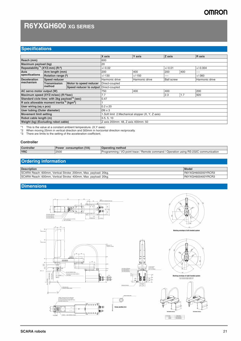
R6YXGH600 XG SERIES
Controller
Specifications
X axis Y axis Z axis R axisReach (mm) 600Maximum payload (kg) 20Repeatability*1 (XYZ:mm) (R:º)
*1 This is the value at a constant ambient temperature. (X,Y axes)
+/-0.02 +/-0.01 +/-0.004Axis specifications
Arm length (mm) 200 400 200 400 ----Rotation range (º) +/-130 +/-150 ---- +/-360
Deceleration mechanism
Speed reducer Harmonic drive Harmonic drive Ball screw Harmonic driveTransmission method
Motor to speed reducer Direct-coupledSpeed reducer to output Direct-coupled
AC servo motor output (W) 750 400 400 200Maximum speed (XYZ:m/sec) (R:º/sec) 7.7 2.3 1.7 920Standard cicle time: with 2kg payload*2 (sec)
*2 When moving 25mm in vertical direction and 300mm in horizontal direction reciprocally.
0.47R axis allowable moment inertia*3 (kgm2)
*3 There are limits to the setting of the acceleration coefficient.
1User wiring (sq x pcs) 0.2 x 20User tubing (Outer diameter) Ø6 x 3Movement limit setting 1.Soft limit 2.Mechanical stopper (X, Y, Z axis)Robot cable length (m) 3.5, 5, 10Weight (kg) (Excluding robot cable) Z axis 200mm: 48, Z axis 400mm: 50
Controller Power consumption (VA) Operating methodYRC 2500 Programming / I/O point trace / Remote command / Operation using RS-232C communication
Ordering information
Description ModelSCARA Reach: 600mm, Vertical Stroke: 200mm, Max. payload: 20kg. R6YXGH600200YRCR3SCARA Reach: 600mm, Vertical Stroke: 400mm, Max. payload: 20kg. R6YXGH600400YRCR3
Dimensions
Cross section A-A
R6YXGH600200
Model Name
400mm
200mm
Z axis stroke
R6YXGH600400
Wid
th a
cros
s flat
24
Hollow diameter Ø18
R6YXGH600 Z200mm R6YXGH600 Z400mm
A A
Ø25h7 0-0.021
200400
50 145
170
80
120
161
220
99
99
189
48
48
0
219
254.5
339.5
476
0
208.7+/-2
273
278
319.5
333.5
368
440
790
990
9886
711
99
12
12
45
14
Ø55
63 128
4-Ø14M12 bolt for installation,4bolt used
M4 ground terminal
15 36 M20X2.5 Depth 20(Bottom of spline)
User tubing 1(Ø6 black)
User tubing 2(Ø6 red)
User tubing 3(Ø6 blue)
5252
35
ZRP
120
19
140
35
User tubing 2(Ø6 red)
User tubing 3(Ø6 blue)
XYP
140160
ZRM
User tubing 1(Ø6 black)
0
XYM90
47
0
Z-Axis lower end
mechanical stopper position
200 Z
-Axi
s st
roke
6m
m r
ise
duri
ng
Z-a
xis
retu
rn-t
o-or
igin
X-axis mechanical stopper position:132°Y-axis mechanical stopper position:152°
Working envelope of right-handed system
Working envelope of left-handed system
150°
130°
130°
100
97°
400
R400
R600
R248
R400
R400
R248
R600
R400
40
0
97°
100
130°
130°
150°
D-sub connector for user wiring
(No.1 to 20 usable)
245 (Base size) (19~89)
(Maximum 770
during arm rotation)
Z
400mm stroke
Z
200mm stroke
User tool installation range
Flat surface has no phase relation to
R-axis origin
4-M4X0.7 through-hole for tool attachment
Four M4X10L binding screws are supplied.
Do not screw the screws in deeper than 10mm
from bottom surface of arm.
400 Z
-Axi
s st
roke
D-sub connector
for user wiring
(No.1 to 20 usable)
SCARA robots
22
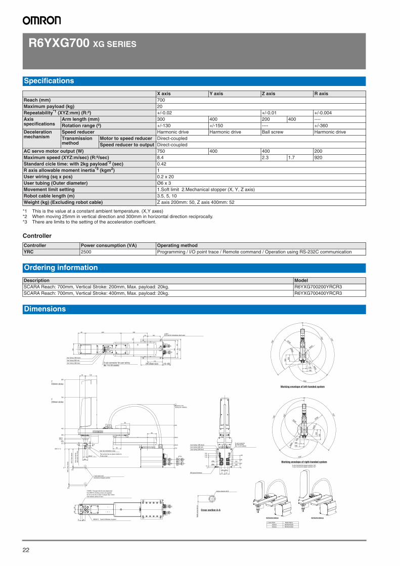
R6YXG700 XG SERIES
Controller
Specifications
X axis Y axis Z axis R axisReach (mm) 700Maximum payload (kg) 20Repeatability*1 (XYZ:mm) (R:º)
*1 This is the value at a constant ambient temperature. (X,Y axes)
+/-0.02 +/-0.01 +/-0.004Axis specifications
Arm length (mm) 300 400 200 400 ----Rotation range (º) +/-130 +/-150 ---- +/-360
Deceleration mechanism
Speed reducer Harmonic drive Harmonic drive Ball screw Harmonic driveTransmission method
Motor to speed reducer Direct-coupledSpeed reducer to output Direct-coupled
AC servo motor output (W) 750 400 400 200Maximum speed (XYZ:m/sec) (R:º/sec) 8.4 2.3 1.7 920Standard cicle time: with 2kg payload*2 (sec)
*2 When moving 25mm in vertical direction and 300mm in horizontal direction reciprocally.
0.42R axis allowable moment inertia*3 (kgm2)
*3 There are limits to the setting of the acceleration coefficient.
1User wiring (sq x pcs) 0.2 x 20User tubing (Outer diameter) Ø6 x 3Movement limit setting 1.Soft limit 2.Mechanical stopper (X, Y, Z axis)Robot cable length (m) 3.5, 5, 10Weight (kg) (Excluding robot cable) Z axis 200mm: 50, Z axis 400mm: 52
Controller Power consumption (VA) Operating methodYRC 2500 Programming / I/O point trace / Remote command / Operation using RS-232C communication
Ordering information
Description ModelSCARA Reach: 700mm, Vertical Stroke: 200mm, Max. payload: 20kg. R6YXG700200YRCR3SCARA Reach: 700mm, Vertical Stroke: 400mm, Max. payload: 20kg. R6YXG700400YRCR3
Dimensions
Cross section A-A
R6YXG700200
Model Name
400mm
200mm
Z axis stroke
R6YXG700400
Hollow diameter Ø18
Wid
th a
cros
s flat
24
A A
(Maximum 770 during arm rotation)
98
12
12
99
86
63 128
300400
50 145
170
80
120
161
0
219
254.5
339.5
476
711
48
48
45
Ø25h7 0-0.021
Ø55
14
0
208.7+/-2
273
278319.5333.5
368
440
790
990
M4 ground terminal
M20X2.5 Depth 20(Bottom of spline)3615
User tubing 3(Ø6 blue)
User tubing 2(Ø6 red)
User tubing 1(Ø6 black)
4-Ø14M12 bolt for installation,4bolt used
5252
35
ZRP
120
19
140
35
User tubing 2(Ø6 red)
User tubing 3(Ø6 blue)
XYP
140160
ZRM
User tubing 1(Ø6 black)
0
XYM
47
0
D-sub connectorfor user wiring(No.1 to 20 usable)
90
220
99
99
189
245 (Base size) (19~89)
Z
400mm stroke
Z
200mm stroke
200 Z
-Axi
s st
roke
6m
m r
ise
duri
ng
axis
ret
urn
-to-
orig
in
400 Z
-Axi
s st
roke
Z-axis lower end
mechanical stopper position
R6YXG700 Z200mm R6YXG700 Z400mm
Working envelope of left-handed system
Working envelope of right-handed systemX-axis mechanical stopper position:132°Y-axis mechanical stopper position:152°
100
140
202
300
130°
150°
124°
130°
R400
R30
R205
R400
R700
R700
R40
0
R205
R400
130°
124°
150°
130°
30
020
2
140
100
R30
D-sub connector for user wiring
(No.1 to 20 usable)
User tool installation range
Flat surface has no phase relation to
R-axis origin
4-M4X0.7 through-hole for tool attachment
Four M4X10L binding screws are supplied.
Do not screw the screws in deeper than 10mm
from bottom surface of arm.
SCARA robots

23SCARA robots
R6YXG800 XG SERIES
Controller
Specifications
X axis Y axis Z axis R axisReach (mm) 800Maximum payload (kg) 20Repeatability*1 (XYZ:mm) (R:º)
*1 This is the value at a constant ambient temperature. (X,Y axes)
+/-0.02 +/-0.01 +/-0.004Axis specifications
Arm length (mm) 400 400 200 400 ----Rotation range (º) +/-130 +/-150 ---- +/-360
Deceleration mechanism
Speed reducer Harmonic drive Harmonic drive Ball screw Harmonic driveTransmission method
Motor to speed reducer Direct-coupledSpeed reducer to output Direct-coupled
AC servo motor output (W) 750 400 400 200Maximum speed (XYZ:m/sec) (R:º/sec) 9.2 2.3 1.7 920Standard cicle time: with 2kg payload*2 (sec)
*2 When moving 25mm in vertical direction and 300mm in horizontal direction reciprocally.
0.48R axis allowable moment inertia*3 (kgm2)
*3 There are limits to the setting of the acceleration coefficient.
1User wiring (sq x pcs) 0.2 x 20User tubing (Outer diameter) Ø6 x 3Movement limit setting 1.Soft limit 2.Mechanical stopper (X, Y, Z axis)Robot cable length (m) 3.5, 5, 10Weight (kg) (Excluding robot cable) Z axis 200mm: 52, Z axis 400mm: 54
Controller Power consumption (VA) Operating methodYRC 2500 Programming / I/O point trace / Remote command / Operation using RS-232C communication
Ordering information
Description ModelSCARA Reach: 800mm, Vertical Stroke: 200mm, Max. payload: 20kg. R6YXG800200YRCR3SCARA Reach: 800mm, Vertical Stroke: 400mm, Max. payload: 20kg. R6YXG800400YRCR3
Dimensions
Cross section A-A
R6YXG800200
Model Name
400mm
200mm
Z axis stroke
R6YXG800400
Hollow diameter Ø18
Wid
th a
cros
s flat
24
R6YXG800 Z200mm R6YXG800 Z400mm
AA
Flat surface has no phase relation to
R-axis origin
50 145
170
161
80 400 400
120
48
48
219
476
339.5
711
254.5
0
333.5
45
Ø55
12
12
Ø25h7 0-0.021
63 128
14
440
790
990
368
319.5278
273
208.7+/-2
0
99
98
86
4-Ø14M12 bolt for installation,4bolt used
User tubing 3(Ø6 blue)
M4 ground terminal
User tubing 2(Ø6 red)
User tubing 1(Ø6 black)
User tool
installation range
ZRM
160140
90
19
140
47
120
0
XYP
ZRP
XYM
0
15 36 M20X2.5 Depth 20(Bottom of spline)
User tubing 1(Ø6 black)
User tubing 2(Ø6 red)
User tubing 3(Ø6 blue)
D-sub connectorfor user wiring(No.1 to 20 usable)
35 35
52 52
220
99
99
189
245 (Base size) (19~89)
Z-axis lower end
mechanical stopper position
400 Z
-Axi
s st
roke 2
00 Z
-Axi
s st
roke
6 m
m r
ise
duri
ng
Z-a
xis
retu
rn-t
o-or
igin
Z
400mm stroke
Z
200mm stroke
Working envelope of left-handed system
Working envelope of right-handed systemX-axis mechanical stopper position:132°Y-axis mechanical stopper position:152°
100
140
202
250
R800
R400
R207
R30
R400
150° 130°
130°
141°
141°
130°
130°
150°
R40
0
R30
R207
R400
R800
25
0
20
2
140
100
D-sub connector for user wiring
(No.1 to 20 usable)
(Maximum 770
during arm rotation)
4-M4X0.7 through-hole for tool attachment
Four M4X10L binding screws are supplied.
Do not screw the screws in deeper than 10mm
from bottom surface of arm.
SCARA robots
24
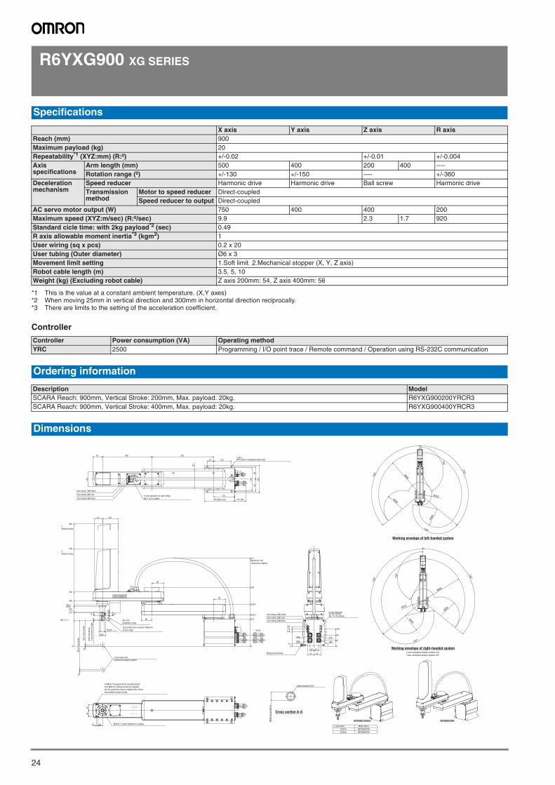
R6YXG900 XG SERIES
Controller
Specifications
X axis Y axis Z axis R axisReach (mm) 900Maximum payload (kg) 20Repeatability*1 (XYZ:mm) (R:º)
*1 This is the value at a constant ambient temperature. (X,Y axes)
+/-0.02 +/-0.01 +/-0.004Axis specifications
Arm length (mm) 500 400 200 400 ----Rotation range (º) +/-130 +/-150 ---- +/-360
Deceleration mechanism
Speed reducer Harmonic drive Harmonic drive Ball screw Harmonic driveTransmission method
Motor to speed reducer Direct-coupledSpeed reducer to output Direct-coupled
AC servo motor output (W) 750 400 400 200Maximum speed (XYZ:m/sec) (R:º/sec) 9.9 2.3 1.7 920Standard cicle time: with 2kg payload*2 (sec)
*2 When moving 25mm in vertical direction and 300mm in horizontal direction reciprocally.
0.49R axis allowable moment inertia*3 (kgm2)
*3 There are limits to the setting of the acceleration coefficient.
1User wiring (sq x pcs) 0.2 x 20User tubing (Outer diameter) Ø6 x 3Movement limit setting 1.Soft limit 2.Mechanical stopper (X, Y, Z axis)Robot cable length (m) 3.5, 5, 10Weight (kg) (Excluding robot cable) Z axis 200mm: 54, Z axis 400mm: 56
Controller Power consumption (VA) Operating methodYRC 2500 Programming / I/O point trace / Remote command / Operation using RS-232C communication
Ordering information
Description ModelSCARA Reach: 900mm, Vertical Stroke: 200mm, Max. payload: 20kg. R6YXG900200YRCR3SCARA Reach: 900mm, Vertical Stroke: 400mm, Max. payload: 20kg. R6YXG900400YRCR3
Dimensions
Cross section A-A
R6YXG900200
Model Name
400mm
200mm
Z axis stroke
R6YXG900400
Wid
th a
cros
s flat
24
Hollow diameter Ø18
R6YXG900 Z200mm R6YXG900 Z400
A A
Flat surface has no phase relation to
R-axis origin
161
170
14550
80 500400
0
254.5
711
339.5
476
219
99
Ø55
45
12
333.5
368
990
0
273
278319.5
790
440
14
12863
Ø25h7 0-0.021
12
208.7+/-2
98
86
120
M4 ground terminal
4-Ø14M12 bolt for installation,4bolt used
48
48
15 36 M20X2.5�Depth 20(Bottom of spline)
User tubing 1(Ø6 black)
User tubing 2(Ø6 red)
User tubing 3(Ø6 blue)
5252
35
ZRP
120
19
140
35
User tubing 2(Ø6 red)
User tubing 3(Ø6 blue)
XYP
140160
ZRM
User tubing 1(Ø6 black)
0
XYM90
47
0
D-sub connectorfor user wiring(No.1 to 20 usable)
220
99
99
189
245 (Base size) (19~89)
Z
400mm stroke
Z
200mm stroke
Z-axis lower end
mechanical stopper position
200 Z
-Axi
s st
roke
400 Z
-Axi
s st
roke
6m
m r
ise
duri
ng
Z-a
xis
retu
rn-t
o-or
igin
X-axis mechanical stopper position:132°
Y-axis mechanical stopper position:152°
Working envelope of right-handed system
Working envelope of left-handed system
R900
R252
R400
R400
150°
130°
130°
150°
150°
130°
130°
150°
R400
R900
R252
R400
D-sub connector for user wiring
(No.1 to 20 usable)
(Maximum 770
during arm rotation)
User tool
installation range
4-M4X0.7 through-hole for tool attachment
Four M4X10L binding screws are supplied.
Do not screw the screws in deeper than 10mm
from bottom surface of arm.
SCARA robots

25SCARA robots
R6YXG1000 XG SERIES
Controller
Specifications
X axis Y axis Z axis R axisReach (mm) 1000Maximum payload (kg) 20Repeatability*1 (XYZ:mm) (R:º)
*1 This is the value at a constant ambient temperature. (X,Y axes)
+/-0.02 +/-0.01 +/-0.004Axis specifications
Arm length (mm) 600 400 200 400 ----Rotation range (º) +/-130 +/-150 ---- +/-360
Deceleration mechanism
Speed reducer Harmonic drive Harmonic drive Ball screw Harmonic driveTransmission method
Motor to speed reducer Direct-coupledSpeed reducer to output Direct-coupled
AC servo motor output (W) 750 400 400 200Maximum speed (XYZ:m/sec) (R:º/sec) 10.6 2.3 1.7 920Standard cicle time: with 2kg payload*2 (sec)
*2 When moving 25mm in vertical direction and 300mm in horizontal direction reciprocally.
0.49R axis allowable moment inertia*3 (kgm2)
*3 There are limits to the setting of the acceleration coefficient
1User wiring (sq x pcs) 0.2 x 20User tubing (Outer diameter) Ø6 x 3Movement limit setting 1.Soft limit 2.Mechanical stopper (X, Y, Z axis)Robot cable length (m) 3.5, 5, 10Weight (kg) (Excluding robot cable) Z axis 200mm: 56, Z axis 400mm: 58
Controller Power consumption (VA) Operating methodYRC 2500 Programming / I/O point trace / Remote command / Operation using RS-232C communication
Ordering information
Description ModelSCARA Reach: 1000mm, Vertical Stroke: 200mm, Max. payload: 20kg. R6YXG1000200YRCR3SCARA Reach: 1000mm, Vertical Stroke: 400mm, Max. payload: 20kg. R6YXG1000400YRCR3
Dimensions
Cross section A-A
Model Name
R6YXG1000200
400mm
200mm
Z axis stroke
R6YXG1000400
Hollow diameter Ø18
Wid
th a
cros
s flat
24
R6YXG1000 Z200 R6YXG1000 Z400
A A
161
50 145
170
80
120
600400
0
254.5
711
339.5
476
219
99
Ø55
45
12
333.5
368
990
0
273
278319.5
790
440
14
12863
Ø25h7 0-0.021
12
208.7+/-2
98
86
4-Ø14M12 bolt for installation,4bolt used
48
48
M4 ground terminal
User tubing 1(Ø6 black)
User tubing 2(Ø6 red)
User tubing 3(Ø6 blue)
15 36 M20X2.5 Depth 20 (Bottom of spline)
5252
35
ZRP
120
19
140
35
User tubing 2(Ø6 red)
User tubing 3(Ø6 blue)
XYP
140160
ZRM
User tubing 1(Ø6 black)
0
XYM90
47
0
220
99
99
189
245 (Base size) (19~89)
Z
400mm stroke
Z
200mm stroke
Z-axis lower end
mechanical stopper position
400 Z
-Axi
s st
roke 200 Z
-Axi
s st
roke
6m
m r
ise
duri
ng
Z-a
xis
retu
rn-t
o-or
igin
X-axis mechanical stopper position:132°Y-axis mechanical stopper position:152°
Working envelope of right-handed system
Working envelope of left-handed system
150°
130°
130°
150°
R400
R1000
R400
R323
R1000
R400
R323
R400
150°
130°
130°
150°
D-sub connector for user wiring
(No.1 to 20 usable)
(Maximum 770
during arm rotation)
User tool
installation range
Flat surface has no phase relation to
R-axis origin
4-M4X0.7 through-hole for tool attachment
Four M4X10L binding screws are supplied.
Do not screw the screws in deeper than 10mm
from bottom surface of arm.
D-sub connector
for user wiring
(No.1 to 20 usable)
SCARA robots
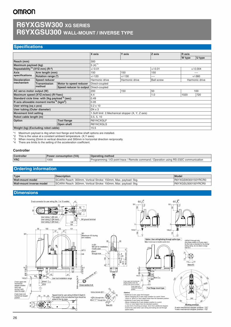
26
R6YXGSW300 XG SERIES
R6YXGSU300 WALL-MOUNT / INVERSE TYPE
Controller
Specifications
X axis Y axis Z axis R axisW type U type
Reach (mm) 300Maximum payload (kg) 5 (4)*1
*1 Maximum payload is 4kg when tool flange and hollow shaft options are installed.
Repeatability*2 (XYZ:mm) (R:º)
*2 This is the value at a constant ambient temperature. (X,Y axes)
+/-0.01 +/-0.01 +/-0.004Axis specifications
Arm length (mm) 150 150 150 ----Rotation range (º) +/-120 +/-130 ---- +/-360
Deceleration mechanism
Speed reducer Harmonic drive Harmonic drive Ball screw Harmonic driveTransmission method
Motor to speed reducer Direct-coupledSpeed reducer to output Direct-coupled
AC servo motor output (W) 200 150 50 100Maximum speed (XYZ:m/sec) (R:º/sec) 4.4 1.0 1020 720Standard cicle time: with 2kg payload*3 (sec)
*3 When moving 25mm in vertical direction and 300mm in horizontal direction reciprocally.
0.49R axis allowable moment inertia*4 (kgm2)
*4 There are limits to the setting of the acceleration coefficient.
0.05User wiring (sq x pcs) 0.2 x 10User tubing (Outer diameter) Ø4 x 3Movement limit setting 1.Soft limit 2.Mechanical stopper (X, Y, Z axis)Robot cable length (m) 3.5, 5, 10Option Tool flange R6YACXGLF
Open shaft R6YACXGLSWeight (kg) (Excluding robot cable) 15.5
Controller Power consumption (VA) Operating methodYRC 1000 Programming / I/O point trace / Remote command / Operation using RS-232C communication
Ordering information
Type Description ModelWall-mount model SCARA Reach: 300mm, Vertical Stroke: 150mm, Max. payload: 5kg. R6YXGSW300150YRCR0Wall-mount inverse model SCARA Reach: 300mm, Vertical Stroke: 150mm, Max. payload: 5kg. R6YXGSU300150YRCR0
Dimensions
43
1238 M4 ground terminal
140
13 2626
126136
User tubing 3 ( 4 blue)User tubing 2 ( 4 black)User tubing 1 ( 4 red)
90
D-sub connector for user wiring (No. 1 to 10 usable)
104
93
A A
B B
014.5355972
148
187.5
381(Maximum 410 duringarm rotation)
42 47
57
016.5
46
94
142±2
51
1230
415
04
16h7 0-0.018
35
User tool installation range
13115015056
381
47
98
Z-axis upper end mechanicalstopper position4mm riseduring Z-axisreturn-to-origin
Z-axis lower endmechanical stopperposition
207050
1010
3939
Tapped hole for user wiring 6-M3x0.5 Depth 6The weight of the tool attached here should beadded to the tip mass
Widt
h ac
ross
flat 1
5
Hollow diameter 11
Cross section A-A
6H7
185.
5 (B
ase
size)
2513
5
8
92.5
2-R
6H7through-hole
4- 9M8 bolt for installation,4 bolts used
60 60
41
Working envelopeX-axis mechanical stopper position: 122°Y-axis mechanical stopper position: 132°
130° 120°
64º240
64º
120º 13
0°
R300
R150
R127
C
0
150
142±2
50127
5
150
Note. Inverse type is installed upside down.Option: User wiring/tubing through spline type
C
0
150
146±2
50127
5
150
View of A
Hollow diameter 11
90º
22.6
7±0.222
.6
22.6
22.6
4H7 +0.0120 through-hole
4- 4.5 through-hole
(Option)• Additional Z-axis upper limit stopper:
Allows changing the Z-axis origin position to a point 12mm,15mm or 18mm (in 3mm steps) lower than the standard position.
• Additional Z-axis lower limit stopper:Allows changing the Z-axis stopper position to a point17mm or more higher than the standard position.(Lower limit of working envelope: 4mm from additional stopper)(Cannot be used when user wiring and tubing are set throughspline shaft.)
A
016.5
46
9451
415
0498
146±230h7
0-0.021
55
4 24610
35
Z-axis upper end mechanicalstopper position 4mm riseduring Z-axis return-to-origin
Z-axis lower endmechanical stopperposition
Tool flange mount type
7.87.8
7.8
7.8
View of C
4-M3x0.5 through-hole(No phase relation to R-axis origin.)As this hole is intended for the wiring/tubing clamp, do not attach a largeload to it.
SCARA robots
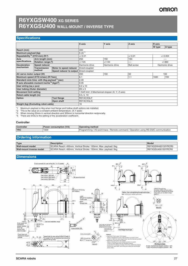
27SCARA robots
R6YXGSW400 XG SERIES
R6YXGSU400 WALL-MOUNT / INVERSE TYPE
Controller
Specifications
X axis Y axis Z axis R axisW type U type
Reach (mm) 400Maximum payload (kg) 5 (4)*1
*1 Maximum payload is 4kg when tool flange and hollow shaft options are installed.
Repeatability*2 (XYZ:mm) (R:º)
*2 This is the value at a constant ambient temperature. (X,Y axes)
+/-0.01 +/-0.01 +/-0.004Axis specifications
Arm length (mm) 250 150 150 ----Rotation range (º) +/-125 +/-144 ---- +/-360
Deceleration mechanism
Speed reducer Harmonic drive Harmonic drive Ball screw Harmonic driveTransmission method
Motor to speed reducer Direct-coupledSpeed reducer to output Direct-coupled
AC servo motor output (W) 200 150 50 100Maximum speed (XYZ:m/sec) (R:º/sec) 6.1 1.1 1020 720Standard cicle time: with 2kg payload*3 (sec)
*3 When moving 25mm in vertical direction and 300mm in horizontal direction reciprocally.
0.49R axis allowable moment inertia*4 (kgm2)
*4 There are limits to the setting of the acceleration coefficient.
0.05User wiring (sq x pcs) 0.2 x 10User tubing (Outer diameter) Ø4 x 3Movement limit setting 1.Soft limit 2.Mechanical stopper (X, Y, Z axis)Robot cable length (m) 3.5, 5, 10Option Tool flange R6YACXGLF
Open shaft R6YACXGLSWeight (kg) (Excluding robot cable) 16
Controller Power consumption (VA) Operating methodYRC 1000 Programming / I/O point trace / Remote command / Operation using RS-232C communication
Ordering information
Type Description ModelWall-mount model SCARA Reach: 400mm, Vertical Stroke: 150mm, Max. payload: 5kg. R6YXGSW400150YRCR0Wall-mount inverse model SCARA Reach: 400mm, Vertical Stroke: 150mm, Max. payload: 5kg. R6YXGSU400150YRCR0
Dimensions
(Option)• Additional Z-axis upper limit stopper:
Allows changing the Z-axis origin position to a point 12mm,15mm or 18mm (in 3mm steps) lower than the standard position.
• Additional Z-axis lower limit stopper:Allows changing the Z-axis stopper position to a point17mm or more higher than the standard position.(Lower limit of working envelope: 4mm from additional stopper)(Cannot be used when user wiring and tubing are set throughspline shaft.)
125° 14
4º
125º
R205
240
R156
125°
144° 125°
R400
R150
Working envelopeX-axis mechanical stopper position: 127°Y-axis mechanical stopper position: 146°
7.87.8
7.8
7.8
View of C
4-M3x0.5 through-hole(No phase relation to R-axis origin.)As this hole is intended for the wiring/tubing clamp, do not attach a largeload to it.
C
0
150
142±2
50127
5
150
Note. Inverse type is installed upside down.Option: User wiring/tubing through spline type
43
1238 M4 ground terminal
140
13 2626
126136
90
D-sub connector for user wiring (No. 1 to 10 usable)
104
93
User tubing 3 ( 4 blue)User tubing 2 ( 4 black)User tubing 1 ( 4 red)
Widt
h ac
ross
flat 1
5
Hollow diameter 11
Cross section A-A
207050
1010
3939
Tapped hole for user wiring 6-M3x0.5 Depth 6The weight of the tool attached here should beadded to the tip mass.
A A
B B
014.5355972
148
187.5
381(Maximum 410 duringarm rotation)
42 47
57
016.5
46
94
142±2
51
1230
415
04
16h7 0-0.018
35
User tool installation range
13125015056
38147
98
n
Z-axis lower endmechanical stopperposition
Z-axis upper endmechanicalstopper position4mm riseduring Z-axisreturn-to-origin
6H7
185.
5 (B
ase
size)
2513
5
8
92.5
2-R
6H7through-hole
4- 9M8 bolt for installation,4 bolts used
60 60
41
View of A
Hollow diameter 11
90º
22.6
7±0.222
.6
22.6
22.6
4H7 +0.0120 through-hole
4- 4.5 through-hole
C
0
150
146±2
50127
5
150
A
016.5
46
9451
415
04
98
146±2
30h7 0-0.021
10 462
35
4
55
Z-axis upper end mechanicalstopper position 4mm riseduring Z-axis return-to-origin
Z-axis lower endmechanical stopperposition
Tool flange mount type
SCARA robots
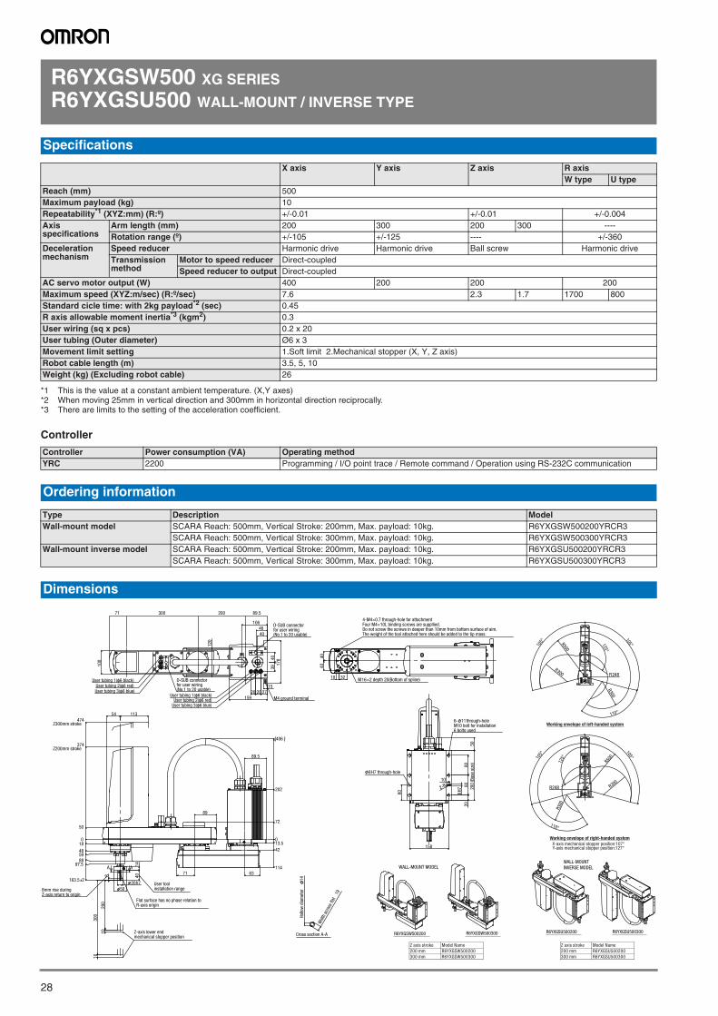
28
R6YXGSW500 XG SERIES
R6YXGSU500 WALL-MOUNT / INVERSE TYPE
Controller
Specifications
X axis Y axis Z axis R axisW type U type
Reach (mm) 500Maximum payload (kg) 10Repeatability*1 (XYZ:mm) (R:º)
*1 This is the value at a constant ambient temperature. (X,Y axes)
+/-0.01 +/-0.01 +/-0.004Axis specifications
Arm length (mm) 200 300 200 300 ----Rotation range (º) +/-105 +/-125 ---- +/-360
Deceleration mechanism
Speed reducer Harmonic drive Harmonic drive Ball screw Harmonic driveTransmission method
Motor to speed reducer Direct-coupledSpeed reducer to output Direct-coupled
AC servo motor output (W) 400 200 200 200Maximum speed (XYZ:m/sec) (R:º/sec) 7.6 2.3 1.7 1700 800Standard cicle time: with 2kg payload*2 (sec)
*2 When moving 25mm in vertical direction and 300mm in horizontal direction reciprocally.
0.45R axis allowable moment inertia*3 (kgm2)
*3 There are limits to the setting of the acceleration coefficient.
0.3User wiring (sq x pcs) 0.2 x 20User tubing (Outer diameter) Ø6 x 3Movement limit setting 1.Soft limit 2.Mechanical stopper (X, Y, Z axis)Robot cable length (m) 3.5, 5, 10Weight (kg) (Excluding robot cable) 26
Controller Power consumption (VA) Operating methodYRC 2200 Programming / I/O point trace / Remote command / Operation using RS-232C communication
Ordering information
Type Description ModelWall-mount model SCARA Reach: 500mm, Vertical Stroke: 200mm, Max. payload: 10kg. R6YXGSW500200YRCR3
SCARA Reach: 500mm, Vertical Stroke: 300mm, Max. payload: 10kg. R6YXGSW500300YRCR3Wall-mount inverse model SCARA Reach: 500mm, Vertical Stroke: 200mm, Max. payload: 10kg. R6YXGSU500200YRCR3
SCARA Reach: 500mm, Vertical Stroke: 300mm, Max. payload: 10kg. R6YXGSU500300YRCR3
Dimensions
X-axis mechanical stopper position:107°Y-axis mechanical stopper position:127°
Working envelope of right-handed system
100
120
178
159
4046
4039
15272020
106
89.520030071
User tubing 1(φ6 black)User tubing 2(φ6 red)User tubing 3(φ6 blue)
User tubing 1(φ6 black)User tubing 2(φ6 red)
User tubing 3(φ6 blue)
D-SUB connectorfor user wiring(No.1 to 20 usable)
D-SUB connectorfor user wiring(No.1 to 20 usable)
M4 ground terminal
4040
3210M16×2 depth 20(Bottom of spline)
4-M4×0.7 through-hole for attachmentFour M4×10L binding screws are suppllied.Do not screw the screws in deeper than 10mm from bottom surface of aim.The weight of the tool attached here should be added to the tip mass.
Wid
th a
cros
s fla
t 19
Hol
low
dia
met
er
14
Cross section A-A
89.5
63
54
4014
20 h7
50
89
71
0
202
406
72
13.5
42
114
113
10
10
200
300
0
485988
97.5
374Z200mm stroke
474Z300mm stroke
163.5 2
50
18
8
A A
Flat surface has no phase relation toR-axis origin
User toolinstallation range8mm rise during
Z-axis return to origin
Z-axis lower endmechanical stopper position
2080
80
60
158
6- 11 through-holeM10 bolt for installation6 bolts used
8H7 through-hole
2-R 200
(Bas
e si
ze)
50
8H
7
10
R6YXGSU500200 R6YXGSU500300R6YXGSW500200 R6YXGSW500300
R500
105°
R248
105°125°
R300
R300
110°
Working envelope of left-handed system
R50010
5°
105°
R248
110°
125°
R300
R300
WALL-MOUNT MODELWALL-MOUNTINVERSE MODEL
Z axis stroke Model Name200 mm R6YXGSW500200300 mm R6YXGSW500300
Z axis stroke Model Name200 mm R6YXGSU500200300 mm R6YXGSU500300
SCARA robots
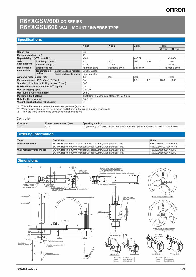
29SCARA robots
R6YXGSW600 XG SERIES
R6YXGSU600 WALL-MOUNT / INVERSE TYPE
Controller
Specifications
X axis Y axis Z axis R axisW type U type
Reach (mm) 600Maximum payload (kg) 10Repeatability*1 (XYZ:mm) (R:º)
*1 This is the value at a constant ambient temperature. (X,Y axes)
+/-0.01 +/-0.01 +/-0.004Axis specifications
Arm length (mm) 300 300 200 300 ----Rotation range (º) +/-130 +/-145 ---- +/-360
Deceleration mechanism
Speed reducer Harmonic drive Harmonic drive Ball screw Harmonic driveTransmission method
Motor to speed reducer Direct-coupledSpeed reducer to output Direct-coupled
AC servo motor output (W) 400 200 200 200Maximum speed (XYZ:m/sec) (R:º/sec) 8.4 2.3 1.7 1700 800Standard cicle time: with 2kg payload*2 (sec)
*2 When moving 25mm in vertical direction and 300mm in horizontal direction reciprocally.
0.46R axis allowable moment inertia*3 (kgm2)
*3 There are limits to the setting of the acceleration coefficient.
0.3User wiring (sq x pcs) 0.2 x 20User tubing (Outer diameter) Ø6 x 3Movement limit setting 1.Soft limit 2.Mechanical stopper (X, Y, Z axis)Robot cable length (m) 3.5, 5, 10Weight (kg) (Excluding robot cable) 27
Controller Power consumption (VA) Operating methodYRC 2200 Programming / I/O point trace / Remote command / Operation using RS-232C communication
Ordering information
Type Description ModelWall-mount model SCARA Reach: 600mm, Vertical Stroke: 200mm, Max. payload: 10kg. R6YXGSW600200YRCR3
SCARA Reach: 600mm, Vertical Stroke: 300mm, Max. payload: 10kg. R6YXGSW600300YRCR3Wall-mount inverse model SCARA Reach: 600mm, Vertical Stroke: 200mm, Max. payload: 10kg. R6YXGSU600200YRCR3
SCARA Reach: 600mm, Vertical Stroke: 300mm, Max. payload: 10kg. R6YXGSU600300YRCR3
Dimensions
X-axis mechanical stopper position:132°Y-axis mechanical stopper position:147°
Working envelope of right-handed system
Wid
th a
cros
s fla
t 19
Hol
low
dia
met
er
14
Cross section A-A
R6YXGSU600200 R6YXGSU600300R6YXGSW600200 R6YXGSW600300
Working envelope of left-handed system
WALL-MOUNT MODELWALL-MOUNTINVERSE MODEL
R600
R180
130°130°
R300
145°
R300
145°
R600130° 130°
R300R180
145°
R300
145°
60
2080
80
200
(Bas
e si
ze)
158
8H7 through-hole
6- 11 through-holeM10 bolt for installation6 bolts used
2-R
8H
7
50
10
4040
10 32M16 ×2 depth 20(Bottom of spline)
4-M4×0.7 through-hole for tool attachmentFour M4×10L binding screw are supplied.Do not screw the screws in deepre than 10mm.from bottom surface of arm.The weight of the tool attached here should be added to the tip mass.
3940
178
15272020
159
4046
106
120
100
89.530030071
User tubing 1(φ6 black)User tubing 2(φ6 red)
User tubing 3(φ6 blue)
User tubing 2(φ6 red)User tubing 3(φ6 blue)
User tubing 1(φ6 black)
D-SUB connectorfor user wiring(No.1 to 20 usable)
D-SUB connectorfor user wiring(No.1 to 20 usable)
M4 ground terminal
63
1440
20h7
50
89.5
54
10
10
200
300
71
89
013.5
42
114
202
439
0
50
374Z200mm stroke
474Z300mm stroke
18
485988
97.5
163.5 2
8
113
A A
User tool installation range
Flat surface has no phase relation toR-axis origin
8mm rise duringZ-axis return to origin
Z-axis lower endmechanical stopper position
Z axis stroke Model Name200 mm R6YXGSW600200300 mm R6YXGSW600300
Z axis stroke Model Name200 mm R6YXGSU600200300 mm R6YXGSU600300
SCARA robots
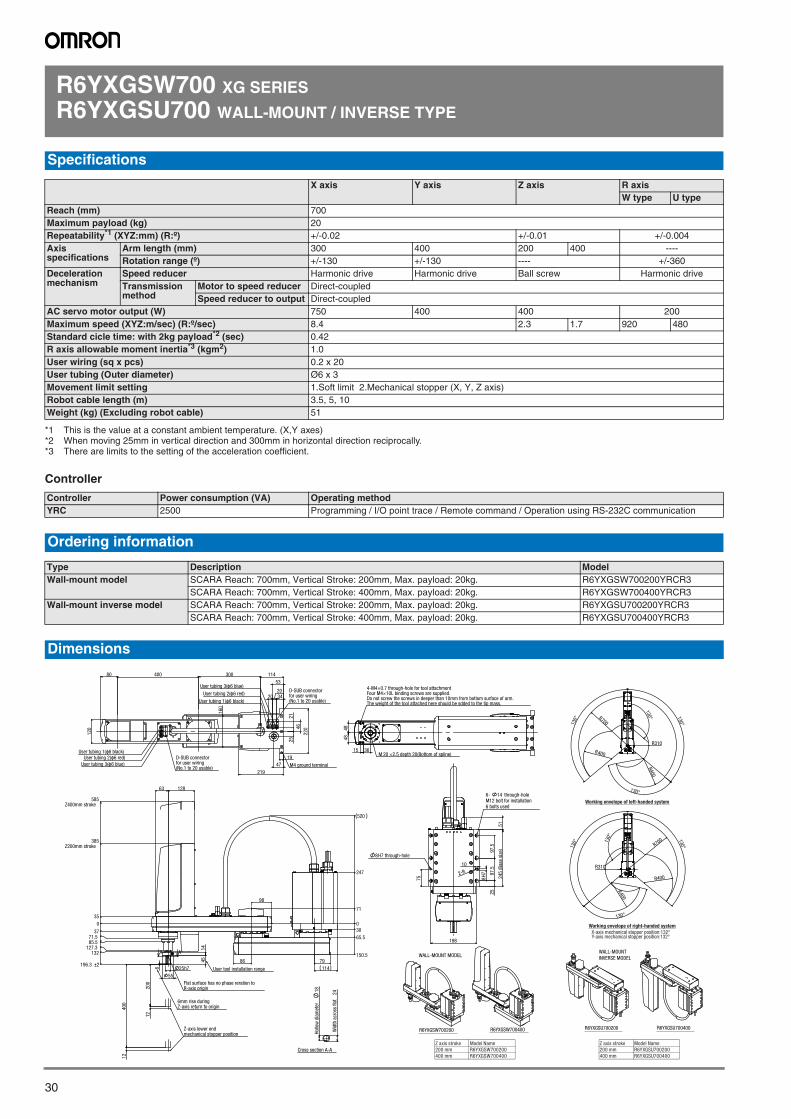
30
R6YXGSW700 XG SERIES
R6YXGSU700 WALL-MOUNT / INVERSE TYPE
Controller
Specifications
X axis Y axis Z axis R axisW type U type
Reach (mm) 700Maximum payload (kg) 20Repeatability*1 (XYZ:mm) (R:º)
*1 This is the value at a constant ambient temperature. (X,Y axes)
+/-0.02 +/-0.01 +/-0.004Axis specifications
Arm length (mm) 300 400 200 400 ----Rotation range (º) +/-130 +/-130 ---- +/-360
Deceleration mechanism
Speed reducer Harmonic drive Harmonic drive Ball screw Harmonic driveTransmission method
Motor to speed reducer Direct-coupledSpeed reducer to output Direct-coupled
AC servo motor output (W) 750 400 400 200Maximum speed (XYZ:m/sec) (R:º/sec) 8.4 2.3 1.7 920 480Standard cicle time: with 2kg payload*2 (sec)
*2 When moving 25mm in vertical direction and 300mm in horizontal direction reciprocally.
0.42R axis allowable moment inertia*3 (kgm2)
*3 There are limits to the setting of the acceleration coefficient.
1.0User wiring (sq x pcs) 0.2 x 20User tubing (Outer diameter) Ø6 x 3Movement limit setting 1.Soft limit 2.Mechanical stopper (X, Y, Z axis)Robot cable length (m) 3.5, 5, 10Weight (kg) (Excluding robot cable) 51
Controller Power consumption (VA) Operating methodYRC 2500 Programming / I/O point trace / Remote command / Operation using RS-232C communication
Ordering information
Type Description ModelWall-mount model SCARA Reach: 700mm, Vertical Stroke: 200mm, Max. payload: 20kg. R6YXGSW700200YRCR3
SCARA Reach: 700mm, Vertical Stroke: 400mm, Max. payload: 20kg. R6YXGSW700400YRCR3Wall-mount inverse model SCARA Reach: 700mm, Vertical Stroke: 200mm, Max. payload: 20kg. R6YXGSU700200YRCR3
SCARA Reach: 700mm, Vertical Stroke: 400mm, Max. payload: 20kg. R6YXGSU700400YRCR3
Dimensions
X-axis mechanical stopper position:132°Y-axis mechanical stopper position:132°
Working envelope of right-handed system
R6YXGSU700200 R6YXGSU700400R6YXGSW700200 R6YXGSW700400
Working envelope of left-handed system
WALL-MOUNT MODELWALL-MOUNTINVERSE MODEL
120
160
114
2521
46
220
47
219
3420
20
53
19
30040080
User tubing 1(φ6 black)
User tubing 1(φ6 black)
User tubing 2(φ6 red)
User tubing 2(φ6 red)
User tubing 3(φ6 blue)
User tubing 3(φ6 blue)
D-SUB connectorfor user wiring(No.1 to 20 usable)
D-SUB connectorfor user wiring(No.1 to 20 usable)
M4 ground terminal
Hol
low
dia
met
er
18
Wid
th a
cros
s fla
t 24
Cross section A-A
79
11425h7
55
4514
12863
200
400
12
12
98
86
0
71
247
520
30
65.5
150.5
6
0
35
385Z200mm stroke
585Z400mm stroke
3771.585.5
127.3132
196.3 2
A A
User tool installation range
Flat surface has no phase reration toR-axis origin
6mm rise duringZ-axis return to origin
Z-axis lower endmechanical stopper position
M 20 ×2.5 depth 20(Bottom of spline)
4848
15 36
4-M4×0.7 through-hole for tool attachmentFour M4×10L binding screws are supplied.Do not screw the screws in deeper than 10mm from bottom surface of arm.The weight of the tool attached here should be sdded to the tip mass.
198
75
8H7 through-hole
2597
.597
.5
245
(Bas
e si
ze)
2-R
6- 14 through-holeM12 bolt for installation6 bolts used
51
8H
7
10
130°
130°
R310
130°R700
R400
R400
130°
R700
130°
130°
R310
R400
R400
130°
130°
Z axis stroke Model Name200 mm R6YXGSW700200400 mm R6YXGSW700400
Z axis stroke Model Name200 mm R6YXGSU700200400 mm R6YXGSU700400
SCARA robots
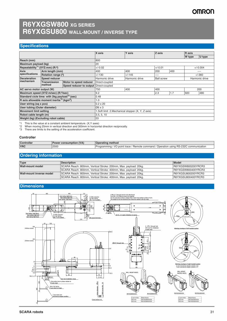
31SCARA robots
R6YXGSW800 XG SERIES
R6YXGSU800 WALL-MOUNT / INVERSE TYPE
Controller
Specifications
X axis Y axis Z axis R axisW type U type
Reach (mm) 800Maximum payload (kg) 20Repeatability*1 (XYZ:mm) (R:º)
*1 This is the value at a constant ambient temperature. (X,Y axes)
+/-0.02 +/-0.01 +/-0.004Axis specifications
Arm length (mm) 400 400 200 400 ----Rotation range (º) +/-130 +/-145 ---- +/-360
Deceleration mechanism
Speed reducer Harmonic drive Harmonic drive Ball screw Harmonic driveTransmission method
Motor to speed reducer Direct-coupledSpeed reducer to output Direct-coupled
AC servo motor output (W) 750 400 400 200Maximum speed (XYZ:m/sec) (R:º/sec) 9.2 2.3 1.7 920 480Standard cicle time: with 2kg payload*2 (sec)
*2 When moving 25mm in vertical direction and 300mm in horizontal direction reciprocally.
0.48R axis allowable moment inertia*3 (kgm2)
*3 There are limits to the setting of the acceleration coefficient.
1.0User wiring (sq x pcs) 0.2 x 20User tubing (Outer diameter) Ø6 x 3Movement limit setting 1.Soft limit 2.Mechanical stopper (X, Y, Z axis)Robot cable length (m) 3.5, 5, 10Weight (kg) (Excluding robot cable) 53
Controller Power consumption (VA) Operating methodYRC 2500 Programming / I/O point trace / Remote command / Operation using RS-232C communication
Ordering information
Type Description ModelWall-mount model SCARA Reach: 800mm, Vertical Stroke: 200mm, Max. payload: 20kg. R6YXGSW800200YRCR3
SCARA Reach: 800mm, Vertical Stroke: 400mm, Max. payload: 20kg. R6YXGSW800400YRCR3Wall-mount inverse model SCARA Reach: 800mm, Vertical Stroke: 200mm, Max. payload: 20kg. R6YXGSU800200YRCR3
SCARA Reach: 800mm, Vertical Stroke: 400mm, Max. payload: 20kg. R6YXGSU800400YRCR3
Dimensions
X-axis mechanical stopper position:132°Y-axis mechanical stopper position:147°
Working envelope of right-handed system
R6YXGSU800200 R6YXGSU800400R6YXGSW800200 R6YXGSW800400
Working envelope of left-handed system
WALL-MOUNT MODELWALL-MOUNTINVERSE MODEL
Hol
low
dia
met
er
18
Wid
th a
cros
s fla
t 24
Cross section A-A
198
75
2597
.597
.5
245
(Bas
e si
ze)
2-R
8H7 through-hole
6- 14 through-holeM12 bolt for installation6 bolts used
8H
7
51
10
M 20 ×2.5 depth 20(Bottom of spline)
4848
15 36
4-M4×0.7 through-hole for tool attachmentFour M4×10L binding screws are supplied.Do not screw the screws in deeper than 10mm from bottom surface of arm.The weight of the tool attached here should be added to the tip mass.
114
160
120
19
47
219
2521
46
220
34
20
20
53
40040080
User tubing 1(φ6 black)
User tubing 1(φ6 black)
User tubing 2(φ6 red)
User tubing 2(φ6 red)
User tubing 3(φ6 blue)
User tubing 3(φ6 blue)
M4 ground terminal
D-SUB connectorfor user wiring(No.1 to 20 usable)
D-SUB connectorfor user wiring(No.1 to 20 usable)
79
114
4514
55
25h7
12863
200
400
6
12
12
86
98
0
71
247
520
30
65.5
150.5
0
35
585Z400mm stroke
385Z200mm stroke
3771.585.5
127.3132
196.3 2
A A
User tool installation range
Flat surface has no phase relation toR-axis origin
6mm rise duringZ-axis return to origin
Z-axis lower endmechanical stopper position
R800
130°
130°
R241
R400
R400
145°
145°
R80013
0°
130°
R241
R400
R400
145°
145°
Z axis stroke Model Name200 mm R6YXGSW800200400 mm R6YXGSW800400
Z axis stroke Model Name200 mm R6YXGSU800200400 mm R6YXGSU800400
SCARA robots
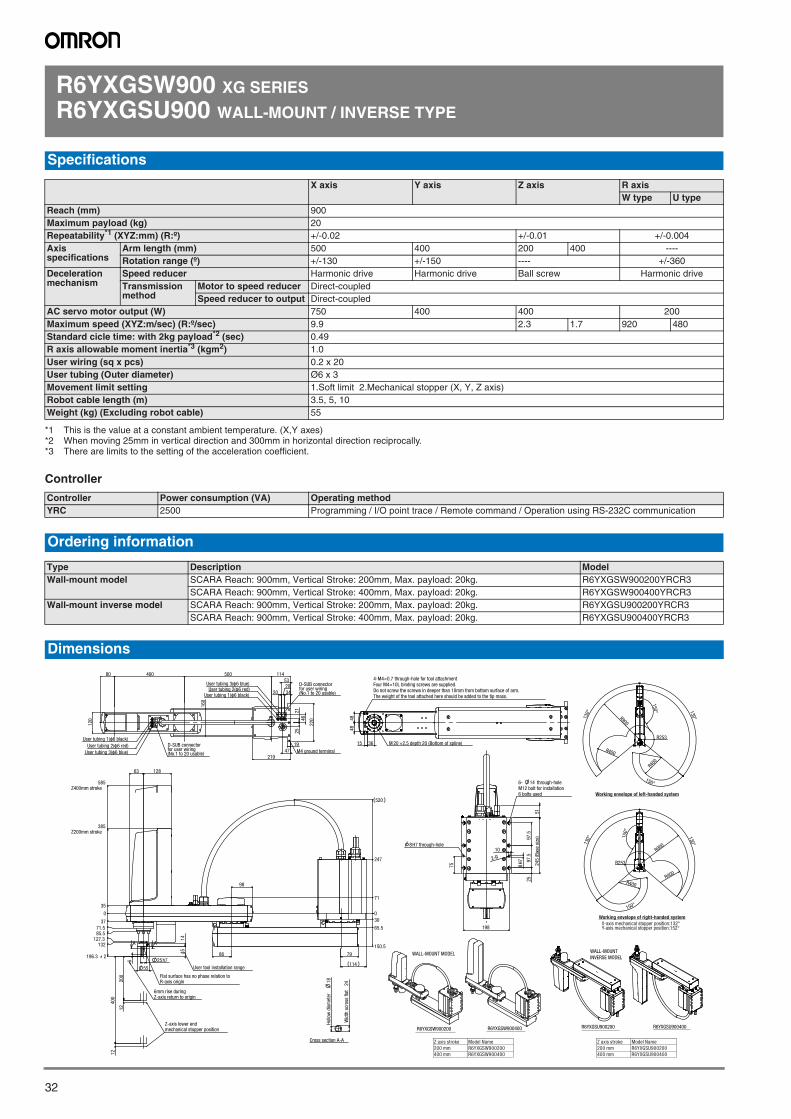
32
R6YXGSW900 XG SERIES
R6YXGSU900 WALL-MOUNT / INVERSE TYPE
Controller
Specifications
X axis Y axis Z axis R axisW type U type
Reach (mm) 900Maximum payload (kg) 20Repeatability*1 (XYZ:mm) (R:º)
*1 This is the value at a constant ambient temperature. (X,Y axes)
+/-0.02 +/-0.01 +/-0.004Axis specifications
Arm length (mm) 500 400 200 400 ----Rotation range (º) +/-130 +/-150 ---- +/-360
Deceleration mechanism
Speed reducer Harmonic drive Harmonic drive Ball screw Harmonic driveTransmission method
Motor to speed reducer Direct-coupledSpeed reducer to output Direct-coupled
AC servo motor output (W) 750 400 400 200Maximum speed (XYZ:m/sec) (R:º/sec) 9.9 2.3 1.7 920 480Standard cicle time: with 2kg payload*2 (sec)
*2 When moving 25mm in vertical direction and 300mm in horizontal direction reciprocally.
0.49R axis allowable moment inertia*3 (kgm2)
*3 There are limits to the setting of the acceleration coefficient.
1.0User wiring (sq x pcs) 0.2 x 20User tubing (Outer diameter) Ø6 x 3Movement limit setting 1.Soft limit 2.Mechanical stopper (X, Y, Z axis)Robot cable length (m) 3.5, 5, 10Weight (kg) (Excluding robot cable) 55
Controller Power consumption (VA) Operating methodYRC 2500 Programming / I/O point trace / Remote command / Operation using RS-232C communication
Ordering information
Type Description ModelWall-mount model SCARA Reach: 900mm, Vertical Stroke: 200mm, Max. payload: 20kg. R6YXGSW900200YRCR3
SCARA Reach: 900mm, Vertical Stroke: 400mm, Max. payload: 20kg. R6YXGSW900400YRCR3Wall-mount inverse model SCARA Reach: 900mm, Vertical Stroke: 200mm, Max. payload: 20kg. R6YXGSU900200YRCR3
SCARA Reach: 900mm, Vertical Stroke: 400mm, Max. payload: 20kg. R6YXGSU900400YRCR3
Dimensions
X-axis mechanical stopper position:132°Y-axis mechanical stopper position:152°
Working envelope of right-handed system
R6YXGSU900200 R6YXGSU900400R6YXGSW900200 R6YXGSW900400
Working envelope of left-handed system
WALL-MOUNT MODELWALL-MOUNTINVERSE MODEL
Hol
low
dia
met
er
18
Wid
th a
cros
s fla
t 24
Cross section A-A
120
160
19
2521
47
34
20
20
53
219
22046
11450040080
M4 ground terminal
User tubing 1(φ6 black)
User tubing 2(φ6 red)
User tubing 3(φ6 blue)
User tubing 1(φ6 black)User tubing 2(φ6 red)
User tubing 3(φ6 blue)
D-SUB connectorfor user wiring(No.1 to 20 usable)
D-SUB connectorfor user wiring(No.1 to 20 usable)
M 20 ×2.5 depth 20 (Bottom of spline)
4848
15 36
4-M4×0.7 through-hole for tool attachmentFour M4×10L binding screws are supplied.Do not screw the screws in deeper than 10mm from bottom surface of arm.The weight of the tool attached here should be added to the tip mass.
114
79
55
25h7
4514
12863
98
86
0
247
65.5
30
150.5
71
520
200
12
1240
0
6
0
35
385Z200mm stroke
585Z400mm stroke
37
71.585.5
132127.3
196.3 2
A A
Flat surface has no phase relation toR-axis origin
User tool installation range
6mm rise duringZ-axis return to origin
Z-axis lower endmechanical stopper position
198
2597
.597
.5
245
(Bas
e si
ze)
75
8H7 through-hole
6- 14 through-holeM12 bolt for installation6 bolts used
2-R
8H
7
51
10
R900
130°
130°
R400
R253
R400
150°
150°
R900
R253
R400
130°
130°
150°
R400
150°
Z axis stroke Model Name200 mm R6YXGSW900200400 mm R6YXGSW900400
Z axis stroke Model Name200 mm R6YXGSU900200400 mm R6YXGSU900400
SCARA robots
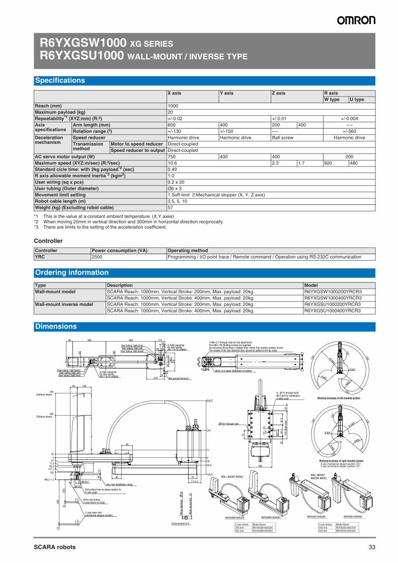
33SCARA robots
R6YXGSW1000 XG SERIES
R6YXGSU1000 WALL-MOUNT / INVERSE TYPE
Controller
Specifications
X axis Y axis Z axis R axisW type U type
Reach (mm) 1000Maximum payload (kg) 20Repeatability*1 (XYZ:mm) (R:º)
*1 This is the value at a constant ambient temperature. (X,Y axes)
+/-0.02 +/-0.01 +/-0.004Axis specifications
Arm length (mm) 600 400 200 400 ----Rotation range (º) +/-130 +/-150 ---- +/-360
Deceleration mechanism
Speed reducer Harmonic drive Harmonic drive Ball screw Harmonic driveTransmission method
Motor to speed reducer Direct-coupledSpeed reducer to output Direct-coupled
AC servo motor output (W) 750 400 400 200Maximum speed (XYZ:m/sec) (R:º/sec) 10.6 2.3 1.7 920 480Standard cicle time: with 2kg payload*2 (sec)
*2 When moving 25mm in vertical direction and 300mm in horizontal direction reciprocally.
0.49R axis allowable moment inertia*3 (kgm2)
*3 There are limits to the setting of the acceleration coefficient.
1.0User wiring (sq x pcs) 0.2 x 20User tubing (Outer diameter) Ø6 x 3Movement limit setting 1.Soft limit 2.Mechanical stopper (X, Y, Z axis)Robot cable length (m) 3.5, 5, 10Weight (kg) (Excluding robot cable) 57
Controller Power consumption (VA) Operating methodYRC 2500 Programming / I/O point trace / Remote command / Operation using RS-232C communication
Ordering information
Type Description ModelWall-mount model SCARA Reach: 1000mm, Vertical Stroke: 200mm, Max. payload: 20kg. R6YXGSW1000200YRCR3
SCARA Reach: 1000mm, Vertical Stroke: 400mm, Max. payload: 20kg. R6YXGSW1000400YRCR3Wall-mount inverse model SCARA Reach: 1000mm, Vertical Stroke: 200mm, Max. payload: 20kg. R6YXGSU1000200YRCR3
SCARA Reach: 1000mm, Vertical Stroke: 400mm, Max. payload: 20kg. R6YXGSU1000400YRCR3
Dimensions
X-axis mechanical stopper position:132°Y-axis mechanical stopper position:152°
Working envelope of right-handed system
R6YXGSU1000200 R6YXGSU1000400R6YXGSW1000200 R6YXGSW1000400
Working envelope of left-handed system
WALL-MOUNT MODELWALL-MOUNTINVERSE MODEL
Hol
low
dia
met
er
18
Wid
th a
cros
s fla
t 24
Cross section A-A
114
120
160
219
1947
2521
4622
0
3420
20
5360040080
User tubing 1(φ6 black)
User tubing 1(φ6 black)
User tubing 2(φ6 red)
User tubing 2(φ6 red)
User tubing 3(φ6 blue)
User tubing 3(φ6 blue)
D-SUB connectorfor user wiring(No.1 to 20 usable)
D-SUB connectorfor user wiring(No.1 to 20 usable)
M4 ground terminal
M20×2.5 depth 20(Bottom of spline)
4848
15 36
4-M4×0.7 through-hole for tool attachmentFour M4×10L binding screws are supplied.Do not screw the screws in deeper than 10mm from bottom surface of arm.The weight of the tool attached here should be added to the tip mass.
198
75
2597
.597
.5
245
(Bas
e si
ze)
8H7 through-hole
2-R
6- 14 through-holeM12 bolt for installation6 bolts used
8H
7
51
10
79
11425h7
55
4514
12863
6
200
400
12
12
86
98
0
71
247
520
30
65.5
150.5
0
35
385Z200mm stroke
585Z400mm stroke
3771.585.5
127.3
196.3 2
132 A A
User tool installation range
Flat surface has no phase relation toR-axis origin
6mm rise duringZ-axis return to origin
Z-axis lower endmechanical stopper position
R1000
130° 130°
R 324
150°
R400
R400
150°
R1000130° 130°
150°
R324
R400
R400
150°
Z axis stroke Model Name200 mm R6YXGSW1000200400 mm R6YXGSW1000400
Z axis stroke Model Name200 mm R6YXGSU1000200400 mm R6YXGSU1000400
SCARA robots
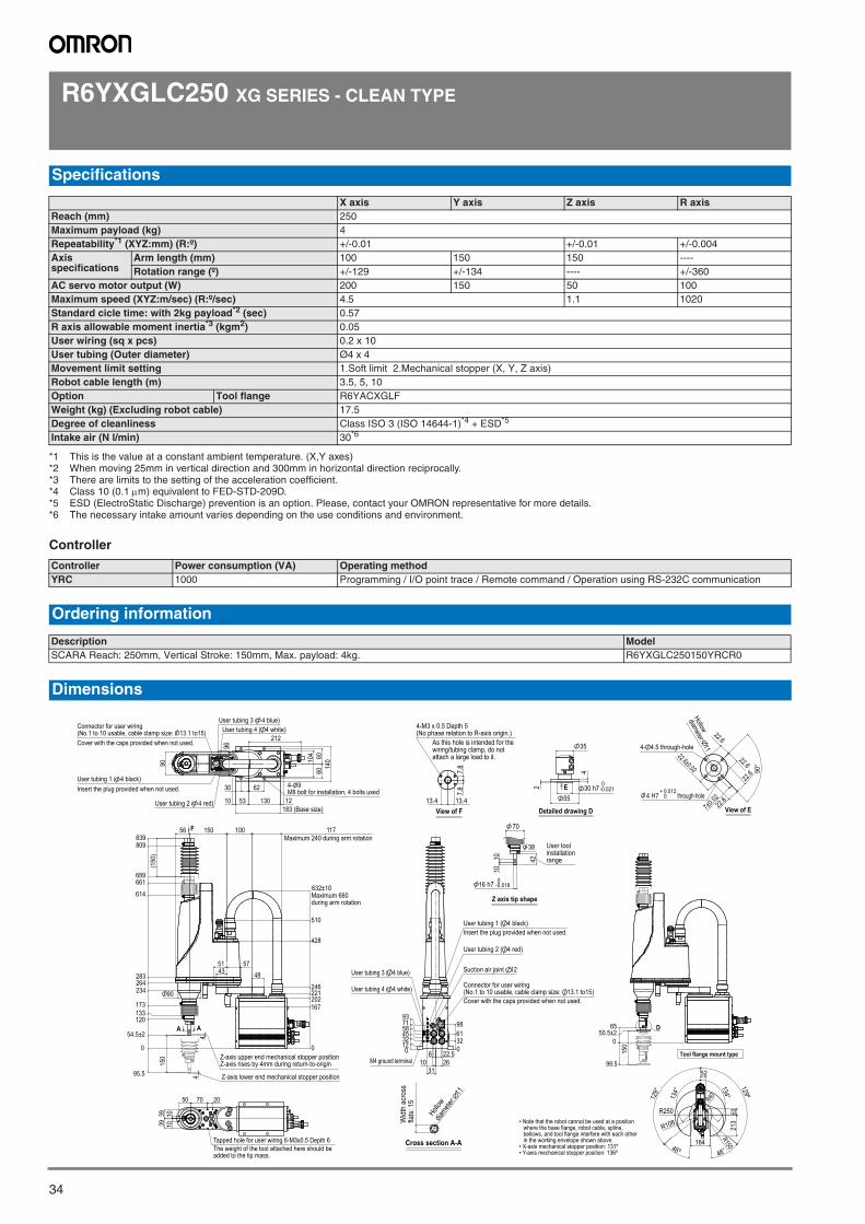
34
R6YXGLC250 XG SERIES - CLEAN TYPE
Controller
Specifications
X axis Y axis Z axis R axisReach (mm) 250Maximum payload (kg) 4Repeatability*1 (XYZ:mm) (R:º)
*1 This is the value at a constant ambient temperature. (X,Y axes)
+/-0.01 +/-0.01 +/-0.004Axis specifications
Arm length (mm) 100 150 150 ----Rotation range (º) +/-129 +/-134 ---- +/-360
AC servo motor output (W) 200 150 50 100Maximum speed (XYZ:m/sec) (R:º/sec) 4.5 1.1 1020Standard cicle time: with 2kg payload*2 (sec)
*2 When moving 25mm in vertical direction and 300mm in horizontal direction reciprocally.
0.57R axis allowable moment inertia*3 (kgm2)
*3 There are limits to the setting of the acceleration coefficient.
0.05User wiring (sq x pcs) 0.2 x 10User tubing (Outer diameter) Ø4 x 4Movement limit setting 1.Soft limit 2.Mechanical stopper (X, Y, Z axis)Robot cable length (m) 3.5, 5, 10Option Tool flange R6YACXGLFWeight (kg) (Excluding robot cable) 17.5Degree of cleanliness Class ISO 3 (ISO 14644-1)*4 + ESD*5
*4 Class 10 (0.1m) equivalent to FED-STD-209D.*5 ESD (ElectroStatic Discharge) prevention is an option. Please, contact your OMRON representative for more details.
Intake air (N l/min) 30*6
*6 The necessary intake amount varies depending on the use conditions and environment.
Controller Power consumption (VA) Operating methodYRC 1000 Programming / I/O point trace / Remote command / Operation using RS-232C communication
Ordering information
Description ModelSCARA Reach: 250mm, Vertical Stroke: 150mm, Max. payload: 4kg. R6YXGLC250150YRCR0
Dimensions
7.8
7.8
13.413.4 View of F
As this hole is intended for thewiring/tubing clamp, do notattach a large load to it.
4-M3 x 0.5 Depth 5(No phase relation to R-axis origin.)
96
62
53 130
104 60
6014
090
212
30
10 12
User tubing 1 ( 4 black)
User tubing 2 ( 4 red)
User tubing 3 ( 4 blue)User tubing 4 ( 4 white)Connector for user wiring
(No.1 to 10 usable, cable clamp size: 13.1 to15)Cover with the caps provided when not used.
Insert the plug provided when not used.
183 (Base size)
4- 9M8 bolt for installation, 4 bolts used
7050 20
39 101039
The weight of the tool attached here should beadded to the tip mass.
Tapped hole for user wiring 6-M3x0.5 Depth 6
0123245587193
0326198
6
312622.5
10
Connector for user wiring(No.1 to 10 usable, cable clamp size: 13.1 to15)
User tubing 2 ( 4 red)
User tubing 1 ( 4 black)
User tubing 4 ( 4 white)
Insert the plug provided when not used.
Cover with the caps provided when not used.
Suction air joint 12 User tubing 3 ( 4 blue)
M4 ground terminal
129°
129º
46º 46°
134°134°
184
R250
R108
R150
213
63
52
R40
• Note that the robot cannot be used at a position where the base flange, robot cable, spline, bellows, and tool flange interfere with each other in the working envelope shown above.
• X-axis mechanical stopper position: 131º• Y-axis mechanical stopper position: 136º
Z-axis upper end mechanical stopper positionZ-axis rises by 4mm during return-to-origin
0
167202221246
428
510
632±10Maximum 660during arm rotation
0
95.5
54.5±2
120133173
234264283
614
661689
809839
44
10015056 117Maximum 240 during arm rotation
575143 48
(150
)15
0
90
F
A A
Z-axis lower end mechanical stopper position
Widt
h ac
ross
flats:
15
Hollow
diamete
r: 11
Cross section A-A
42
16 h7 -0.0180
1010
70
User toolinstallationrange
38
Z axis tip shape
0
99.5
50.5±265
150
D
Tool flange mount type
-0.0210
55
2
4
35
Detailed drawing D
E 30 h7
7±0.02
22.6
22.6
22.6
22.622.6±0.02 90
°
0+ 0.012
through-hole
View of E
4 H7
4- 4.5 through-hole
Hollow
diameter: 11
SCARA robots
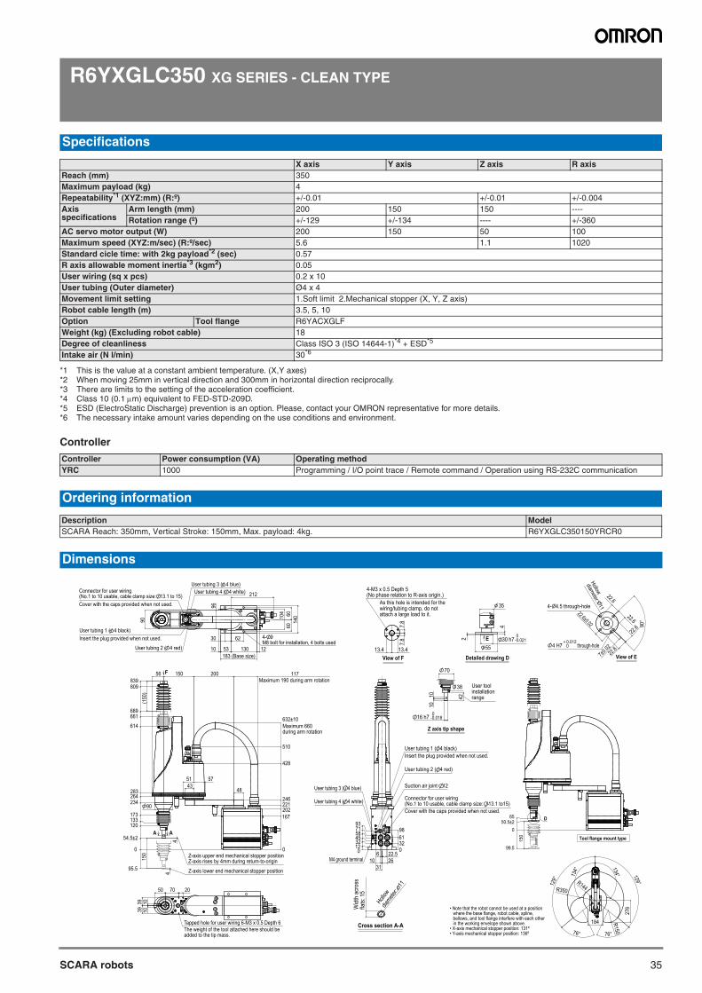
35SCARA robots
R6YXGLC350 XG SERIES - CLEAN TYPE
Controller
Specifications
X axis Y axis Z axis R axisReach (mm) 350Maximum payload (kg) 4Repeatability*1 (XYZ:mm) (R:º)
*1 This is the value at a constant ambient temperature. (X,Y axes)
+/-0.01 +/-0.01 +/-0.004Axis specifications
Arm length (mm) 200 150 150 ----Rotation range (º) +/-129 +/-134 ---- +/-360
AC servo motor output (W) 200 150 50 100Maximum speed (XYZ:m/sec) (R:º/sec) 5.6 1.1 1020Standard cicle time: with 2kg payload*2 (sec)
*2 When moving 25mm in vertical direction and 300mm in horizontal direction reciprocally.
0.57R axis allowable moment inertia*3 (kgm2)
*3 There are limits to the setting of the acceleration coefficient.
0.05User wiring (sq x pcs) 0.2 x 10User tubing (Outer diameter) Ø4 x 4Movement limit setting 1.Soft limit 2.Mechanical stopper (X, Y, Z axis)Robot cable length (m) 3.5, 5, 10Option Tool flange R6YACXGLFWeight (kg) (Excluding robot cable) 18Degree of cleanliness Class ISO 3 (ISO 14644-1)*4 + ESD*5
*4 Class 10 (0.1m) equivalent to FED-STD-209D.*5 ESD (ElectroStatic Discharge) prevention is an option. Please, contact your OMRON representative for more details.
Intake air (N l/min) 30*6
*6 The necessary intake amount varies depending on the use conditions and environment.
Controller Power consumption (VA) Operating methodYRC 1000 Programming / I/O point trace / Remote command / Operation using RS-232C communication
Ordering information
Description ModelSCARA Reach: 350mm, Vertical Stroke: 150mm, Max. payload: 4kg. R6YXGLC350150YRCR0
Dimensions
7.8
7.8
13.413.4 View of F
As this hole is intended for thewiring/tubing clamp, do notattach a large load to it.
4-M3 x 0.5 Depth 5(No phase relation to R-axis origin.)
0123245587193
0326198
6
312622.5
10
Connector for user wiring(No.1 to 10 usable, cable clamp size: 13.1 to15)
User tubing 2 ( 4 red)
User tubing 1 ( 4 black)
User tubing 4 ( 4 white)
Insert the plug provided when not used.
Cover with the caps provided when not used.
Suction air joint 12 User tubing 3 ( 4 blue)
M4 ground terminal
• Note that the robot cannot be used at a position where the base flange, robot cable, spline, bellows, and tool flange interfere with each other in the working envelope shown above.
• X-axis mechanical stopper position: 131º• Y-axis mechanical stopper position: 136º
Widt
h ac
ross
flats:
15
Hollow
diamete
r: 11
Cross section A-A
42
16 h7 -0.0180
1010
70
User toolinstallationrange
38
Z axis tip shape
-0.0210
55
2
4
35
Detailed drawing D
E 30 h7
7±0.02
22.6
22.6
22.6
22.622.6±0.02 90
°0
+ 0.012through-hole
View of E
4 H7
4- 4.5 through-hole
Hollow
diameter: 11
129°
129°
134°
134°
76° 76°
184
R350
R150
R144
276
96
62
53 130183 (Base size)
104 60
6014
0
90
212
30
10 12
Connector for user wiring(No.1 to 10 usable, cable clamp size: 13.1 to 15)Cover with the caps provided when not used.
User tubing 1 ( 4 black)Insert the plug provided when not used.
User tubing 2 ( 4 red)
User tubing 3 ( 4 blue)User tubing 4 ( 4 white)
4- 9M8 bolt for installation, 4 bolts used
90
0
167202221246
428
510
632±10Maximum 660during arm rotation
0
95.5
54.5±2
120133173
234264283
614
661689
809839
44
20015056 117Maximum 190 during arm rotation
575143
48
(150
)15
0
F
A A
Z-axis upper end mechanical stopper positionZ-axis rises by 4mm during return-to-origin
Z-axis lower end mechanical stopper position
7050 20
39 101039
The weight of the tool attached here should beadded to the tip mass.
Tapped hole for user wiring 6-M3 x 0.5 Depth 6
0
99.5
50.5±265
150
D
Tool flange mount type
SCARA robots
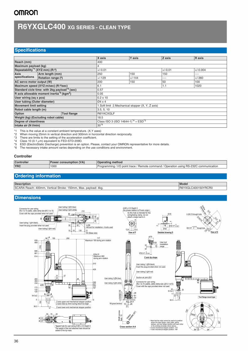
36
R6YXGLC400 XG SERIES - CLEAN TYPE
Controller
Specifications
X axis Y axis Z axis R axisReach (mm) 400Maximum payload (kg) 4Repeatability*1 (XYZ:mm) (R:º)
*1 This is the value at a constant ambient temperature. (X,Y axes)
+/-0.01 +/-0.01 +/-0.004Axis specifications
Arm length (mm) 250 150 150 ----Rotation range (º) +/-129 +/-144 ---- +/-360
AC servo motor output (W) 200 150 50 100Maximum speed (XYZ:m/sec) (R:º/sec) 6.1 1.1 1020Standard cicle time: with 2kg payload*2 (sec)
*2 When moving 25mm in vertical direction and 300mm in horizontal direction reciprocally.
0.57R axis allowable moment inertia*3 (kgm2)
*3 There are limits to the setting of the acceleration coefficient.
0.05User wiring (sq x pcs) 0.2 x 10User tubing (Outer diameter) Ø4 x 4Movement limit setting 1.Soft limit 2.Mechanical stopper (X, Y, Z axis)Robot cable length (m) 3.5, 5, 10Option Tool flange R6YACXGLFWeight (kg) (Excluding robot cable) 18.5Degree of cleanliness Class ISO 3 (ISO 14644-1)*4 + ESD*5
*4 Class 10 (0.1m) equivalent to FED-STD-209D.*5 ESD (ElectroStatic Discharge) prevention is an option. Please, contact your OMRON representative for more details.
Intake air (N l/min) 30*6
*6 The necessary intake amount varies depending on the use conditions and environment.
Controller Power consumption (VA) Operating methodYRC 1000 Programming / I/O point trace / Remote command / Operation using RS-232C communication
Ordering information
Description ModelSCARA Reach: 400mm, Vertical Stroke: 150mm, Max. payload: 4kg. R6YXGLC400150YRCR0
Dimensions
7.8
7.8
13.413.4 View of F
As this hole is intended for thewiring/tubing clamp, do notattach a large load to it.
4-M3 x 0.5 Depth 5(No phase relation to R-axis origin.)
0123245587193
0326198
6
312622.5
10
Connector for user wiring(No.1 to 10 usable, cable clamp size: 13.1 to15)
User tubing 2 ( 4 red)
User tubing 1 ( 4 black)
User tubing 4 ( 4 white)
Insert the plug provided when not used.
Cover with the caps provided when not used.
Suction air joint 12 User tubing 3 ( 4 blue)
M4 ground terminal
• Note that the robot cannot be used at a position where the base flange, robot cable, spline, bellows, and tool flange interfere with each other in the working envelope shown above.
• X-axis mechanical stopper position: 131º• Y-axis mechanical stopper position: 146º
Widt
h ac
ross
flats:
15
Hollow
diamete
r: 11
Cross section A-A
42
16 h7 -0.0180
1010
70
User toolinstallationrange
38
Z axis tip shape
-0.0210
55
2
4
35
Detailed drawing D
E 30 h7
7±0.02
22.6
22.6
22.6
22.622.6±0.02 90
°
0+ 0.012
through-hole
View of E
4 H7
4- 4.5 through-hole
Hollow
diameter: 11
129°
129º
94° 94°
144°
144°
184
R156R400
307
R150
96
62
53 130
104 60
6014
0
90
212
30
10 12183 (Base size)
Connector for user wiring(No.1 to 10 usable, cable clamp size: 13.1 to 15)Cover with the caps provided when not used.
User tubing 1 ( 4 black)Insert the plug provided when not used.
User tubing 2 ( 4 red)
User tubing 3 ( 4 blue)User tubing 4 ( 4 white)
4- 9M8 bolt for installation, 4 bolts used
117F
0
167202221246
428
510
632±10
0
95.5
54.5±2
120133173
234264283
614661689
809839
44
25015056
575143 48
(150
)15
0
A A
90
Z-axis upper end mechanical stopper positionZ-axis rises by 4mm during return-to-origin
Z-axis lower end mechanical stopper position
Maximum 660during arm rotation
Maximum 190 during arm rotation
7050 20
39 101039
The weight of the tool attached here should beadded to the tip mass.
Tapped hole for user wiring 6-M3 x 0.5 Depth 6
050.5±2
65
150
D
99.5Tool flange mount type
SCARA robots
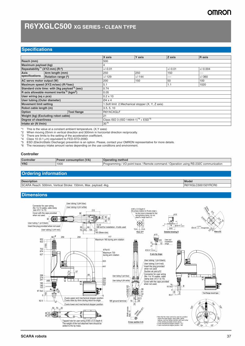
37SCARA robots
R6YXGLC500 XG SERIES - CLEAN TYPE
Controller
Specifications
X axis Y axis Z axis R axisReach (mm) 500Maximum payload (kg) 4Repeatability*1 (XYZ:mm) (R:º)
*1 This is the value at a constant ambient temperature. (X,Y axes)
+/-0.01 +/-0.01 +/-0.004Axis specifications
Arm length (mm) 250 250 150 ----Rotation range (º) +/-129 +/-144 ---- +/-360
AC servo motor output (W) 200 150 50 100Maximum speed (XYZ:m/sec) (R:º/sec) 5.1 1.1 1020Standard cicle time: with 2kg payload*2 (sec)
*2 When moving 25mm in vertical direction and 300mm in horizontal direction reciprocally.
0.74R axis allowable moment inertia*3 (kgm2)
*3 There are limits to the setting of the acceleration coefficient.
0.05User wiring (sq x pcs) 0.2 x 10User tubing (Outer diameter) Ø4 x 4Movement limit setting 1.Soft limit 2.Mechanical stopper (X, Y, Z axis)Robot cable length (m) 3.5, 5, 10Option Tool flange R6YACXGLFWeight (kg) (Excluding robot cable) 21Degree of cleanliness Class ISO 3 (ISO 14644-1)*4 + ESD*5
*4 Class 10 (0.1m) equivalent to FED-STD-209D.*5 ESD (ElectroStatic Discharge) prevention is an option. Please, contact your OMRON representative for more details.
Intake air (N l/min) 30*6
*6 The necessary intake amount varies depending on the use conditions and environment.
Controller Power consumption (VA) Operating methodYRC 1000 Programming / I/O point trace / Remote command / Operation using RS-232C communication
Ordering information
Description ModelSCARA Reach: 500mm, Vertical Stroke: 150mm, Max. payload: 4kg. R6YXGLC500150YRCR0
Dimensions
7.8
7.8
13.413.4 View of F
As this hole is intended for thewiring/tubing clamp, do notattach a large load to it.
4-M3 x 0.5 Depth 5(No phase relation to R-axis origin.)
• Note that the robot cannot be used at a position where the base flange, robot cable, spline, bellows, and tool flange interfere with each other in the working envelope shown above.
• X-axis mechanical stopper position: 131º• Y-axis mechanical stopper position: 146º
Widt
h ac
ross
flats:
15
Hollow
diamete
r: 11
Cross section A-A
42
16 h7 -0.0180
1010
70
User toolinstallationrange
38
Z axis tip shape
-0.0210
55
2
4
35
Detailed drawing D
E 30 h7
7±0.02
22.6
22.6
22.6
22.622.6±0.02 90
°
0+ 0.012
through-hole
View of E
4 H7
Hollow
diameter: 11
129°
129°
75º 75º
144° 144°
184
R155
R500
407
R250
96
6253 130
183 (Base size)
104 60
60 14090
212
3010 12
Connector for user wiring(No.1 to 10 usable, cable clamp size: 13.1 to 15) Cover with the caps providedwhen not used.
User tubing 1 ( 4 black)Insert the plug provided when not used.
User tubing 2 ( 4 red)
User tubing 3 ( 4 blue)
User tubing 4 ( 4 white)
4- 9M8 bolt for installation, 4 bolts used
0
167202221256
441
523
675±10
0
82.5
67.5±2133146186247274296
627674702
822852
44
25025056 117
575143 48
(150
)15
0
F
90
A A
Z-axis upper end mechanical stopper positionZ-axis rises by 4mm during return-to-origin
Z-axis lower end mechanical stopper position
Maximum 730during arm rotation
Maximum 160 during arm rotation
50
1010
3939
70 20
The weight of the tool attached here should beadded to the tip mass.
Tapped hole for user wiring 4-M3 x 0.5 Depth 6
0123245587193
0326198
6
312622.5
10
User tubing 1 ( 4 black)
Insert the plug providedwhen not used
User tubing 2 ( 4 red)
Suction air joint 12
Connector for user wiring(No.1 to 10 usable, cableclamp size: 13.1 to 15)Cover with the caps providedwhen not used.
User tubing 4 ( 4 white)
User tubing 3 ( 4 blue)
M4 ground terminal
Tool flange mount type
0
86.5
63.5±278
150
D
SCARA robots
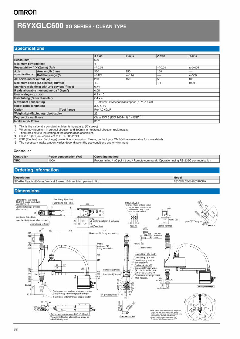
38
R6YXGLC600 XG SERIES - CLEAN TYPE
Controller
Specifications
X axis Y axis Z axis R axisReach (mm) 600Maximum payload (kg) 4Repeatability*1 (XYZ:mm) (R:º)
*1 This is the value at a constant ambient temperature. (X,Y axes)
+/-0.01 +/-0.01 +/-0.004Axis specifications
Arm length (mm) 350 250 150 ----Rotation range (º) +/-129 +/-144 ---- +/-360
AC servo motor output (W) 200 150 50 100Maximum speed (XYZ:m/sec) (R:º/sec) 4.9 1.1 1020Standard cicle time: with 2kg payload*2 (sec)
*2 When moving 25mm in vertical direction and 300mm in horizontal direction reciprocally.
0.74R axis allowable moment inertia*3 (kgm2)
*3 There are limits to the setting of the acceleration coefficient.
0.05User wiring (sq x pcs) 0.2 x 10User tubing (Outer diameter) Ø4 x 4Movement limit setting 1.Soft limit 2.Mechanical stopper (X, Y, Z axis)Robot cable length (m) 3.5, 5, 10Option Tool flange R6YACXGLFWeight (kg) (Excluding robot cable) 22Degree of cleanliness Class ISO 3 (ISO 14644-1)*4 + ESD*5
*4 Class 10 (0.1m) equivalent to FED-STD-209D.*5 ESD (ElectroStatic Discharge) prevention is an option. Please, contact your OMRON representative for more details.
Intake air (N l/min) 30*6
*6 The necessary intake amount varies depending on the use conditions and environment.
Controller Power consumption (VA) Operating methodYRC 1000 Programming / I/O point trace / Remote command / Operation using RS-232C communication
Ordering information
Description ModelSCARA Reach: 600mm, Vertical Stroke: 150mm, Max. payload: 4kg. R6YXGLC600150YRCR0
Dimensions
7.8
7.8
13.413.4 View of F
As this hole is intended for thewiring/tubing clamp, do notattach a large load to it.
4-M3 x 0.5 Depth 5(No phase relation to R-axis origin.)
• Note that the robot cannot be used at a position where the base flange, robot cable, spline, bellows, and tool flange interfere with each other in the working envelope shown above.
• X-axis mechanical stopper position: 131º• Y-axis mechanical stopper position: 146º
Widt
h ac
ross
flats:
15
Hollow
diamete
r: 11
Cross section A-A
42
16 h7 -0.0180
1010
70
User toolinstallationrange
38
Z axis tip shape
-0.0210
55
2
4
35
Detailed drawing D
E 30 h7
7±0.02
22.6
22.6
22.6
22.622.6±0.02 90
°
0+ 0.012
through-hole
View of E
4 H7
Hollow
diameter: 11
0123245587193
0326198
6
312622.5
10
User tubing 1 ( 4 black)
Insert the plug providedwhen not used
User tubing 2 ( 4 red)
Suction air joint 12
Connector for user wiring(No.1 to 10 usable, cableclamp size: 13.1 to 15)Cover with the caps providedwhen not used.
User tubing 4 ( 4 white)
User tubing 3 ( 4 blue)
M4 ground terminal
96
6253 130
183 (Base size)
104 60
6014
0
4- 9M8 bolt for installation, 4 bolts used
90
212
3010 12
Connector for user wiring(No.1 to 10 usable, cable clampsize: 13.1 to 15) Cover with the caps providedwhen not used.
User tubing 1 ( 4 black)Insert the plug provided when not used.
User tubing 2 ( 4 red)
User tubing 3 ( 4 blue)User tubing 4 ( 4 white)
0
167202221256
441
523
675±10Maximum 740during arm rotation
0
82.5
67.5±2133146186247274296
627674702
822852
44
35025056 117Maximum 170 during arm rotation
575143 48
(150
)15
0
Z-axis lower end mechanical stopper position
Z-axis upper end mechanical stopper positionZ-axis rises by 4mm during return-to-origin
F
A A
90
50
1010
3939
70 20
The weight of the tool attached here should beadded to the tip mass.
Tapped hole for user wiring 4-M3 x 0.5 Depth 6
129°
129°
144° 144º
97º 97º
R600
R208
184
R250
0
86.5
63.5±278
150
D
Tool flange mount type
SCARA robots
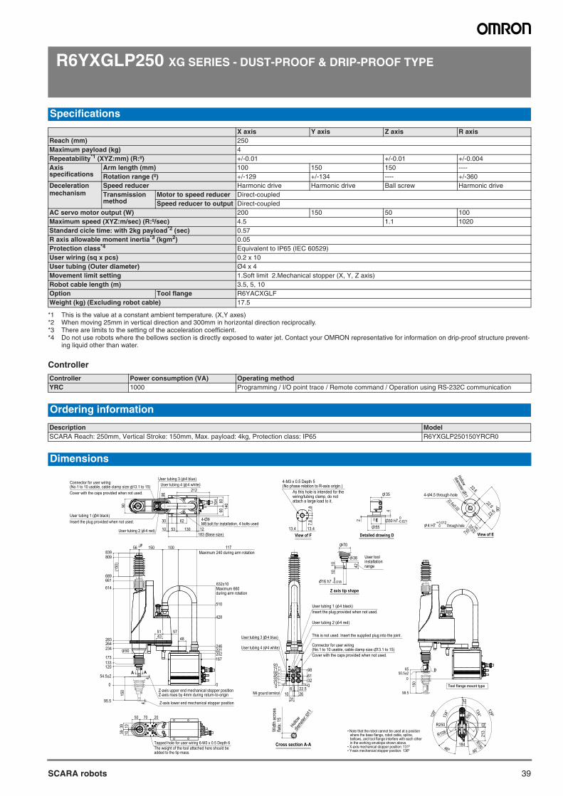
39SCARA robots
R6YXGLP250 XG SERIES - DUST-PROOF & DRIP-PROOF TYPE
Controller
Specifications
X axis Y axis Z axis R axisReach (mm) 250Maximum payload (kg) 4Repeatability*1 (XYZ:mm) (R:º)
*1 This is the value at a constant ambient temperature. (X,Y axes)
+/-0.01 +/-0.01 +/-0.004Axis specifications
Arm length (mm) 100 150 150 ----Rotation range (º) +/-129 +/-134 ---- +/-360
Deceleration mechanism
Speed reducer Harmonic drive Harmonic drive Ball screw Harmonic driveTransmission method
Motor to speed reducer Direct-coupledSpeed reducer to output Direct-coupled
AC servo motor output (W) 200 150 50 100Maximum speed (XYZ:m/sec) (R:º/sec) 4.5 1.1 1020Standard cicle time: with 2kg payload*2 (sec)
*2 When moving 25mm in vertical direction and 300mm in horizontal direction reciprocally.
0.57R axis allowable moment inertia*3 (kgm2)
*3 There are limits to the setting of the acceleration coefficient.
0.05Protection class*4
*4 Do not use robots where the bellows section is directly exposed to water jet. Contact your OMRON representative for information on drip-proof structure prevent-ing liquid other than water.
Equivalent to IP65 (IEC 60529)User wiring (sq x pcs) 0.2 x 10User tubing (Outer diameter) Ø4 x 4Movement limit setting 1.Soft limit 2.Mechanical stopper (X, Y, Z axis)Robot cable length (m) 3.5, 5, 10Option Tool flange R6YACXGLFWeight (kg) (Excluding robot cable) 17.5
Controller Power consumption (VA) Operating methodYRC 1000 Programming / I/O point trace / Remote command / Operation using RS-232C communication
Ordering information
Description ModelSCARA Reach: 250mm, Vertical Stroke: 150mm, Max. payload: 4kg, Protection class: IP65 R6YXGLP250150YRCR0
Dimensions
7.8
7.8
13.413.4 View of F
As this hole is intended for thewiring/tubing clamp, do notattach a large load to it.
4-M3 x 0.5 Depth 5(No phase relation to R-axis origin.)
• Note that the robot cannot be used at a position where the base flange, robot cable, spline, bellows, and tool flange interfere with each other in the working envelope shown above.
• X-axis mechanical stopper position: 131º• Y-axis mechanical stopper position: 136º
Widt
h ac
ross
flats:
15
Hollow
diamete
r: 11
Cross section A-A
42
16 h7 -0.0180
1010
70
User toolinstallationrange
38
Z axis tip shape
-0.0210
55
2
4
35
Detailed drawing D
E 30 h7
7±0.02
22.6
22.6
22.6
22.622.6±0.02 90
°
0+ 0.012
through-hole
View of E
4 H7
4- 4.5 through-hole
Hollow
diameter: 11
0
99.5
50.5±265
150
D
Tool flange mount type
129°
129º
46º 46°
134°134°
184
R250
R108
R150
213
63
52
R40
0123245587193
0326198
6
312622.5
10
Connector for user wiring(No.1 to 10 usable, cable clamp size: 13.1 to 15)
User tubing 2 ( 4 red)
User tubing 1 ( 4 black)
User tubing 4 ( 4 white)
Insert the plug provided when not used.
Cover with the caps provided when not used.
This is not used. Insert the supplied plug into the joint . User tubing 3 ( 4 blue)
M4 ground terminal
96
62
53 130
104 60
6014
090
212
30
10 12
User tubing 1 ( 4 black)
User tubing 2 ( 4 red)
User tubing 3 ( 4 blue)User tubing 4 ( 4 white)Connector for user wiring
(No.1 to 10 usable, cable clamp size: 13.1 to 15)Cover with the caps provided when not used.
Insert the plug provided when not used.
183 (Base size)
4- 9M8 bolt for installation, 4 bolts used
Z-axis upper end mechanical stopper positionZ-axis rises by 4mm during return-to-origin
0
167202221246
428
510
632±10Maximum 660during arm rotation
0
95.5
54.5±2
120133173
234264283
614
661689
809839
44
10015056 117Maximum 240 during arm rotation
575143 48
(150
)15
0
90
F
A A
Z-axis lower end mechanical stopper position
7050 20
39 101039
The weight of the tool attached here should beadded to the tip mass.
Tapped hole for user wiring 6-M3 x 0.5 Depth 6
SCARA robots
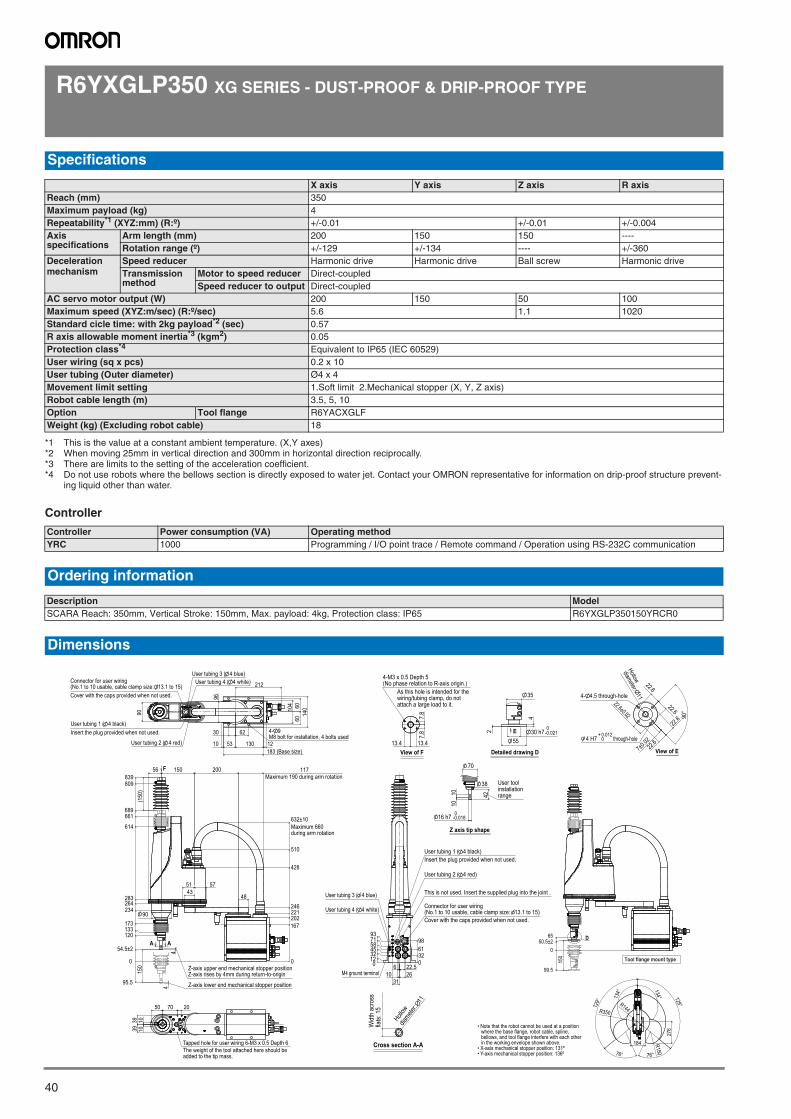
40
R6YXGLP350 XG SERIES - DUST-PROOF & DRIP-PROOF TYPE
Controller
Specifications
X axis Y axis Z axis R axisReach (mm) 350Maximum payload (kg) 4Repeatability*1 (XYZ:mm) (R:º)
*1 This is the value at a constant ambient temperature. (X,Y axes)
+/-0.01 +/-0.01 +/-0.004Axis specifications
Arm length (mm) 200 150 150 ----Rotation range (º) +/-129 +/-134 ---- +/-360
Deceleration mechanism
Speed reducer Harmonic drive Harmonic drive Ball screw Harmonic driveTransmission method
Motor to speed reducer Direct-coupledSpeed reducer to output Direct-coupled
AC servo motor output (W) 200 150 50 100Maximum speed (XYZ:m/sec) (R:º/sec) 5.6 1.1 1020Standard cicle time: with 2kg payload*2 (sec)
*2 When moving 25mm in vertical direction and 300mm in horizontal direction reciprocally.
0.57R axis allowable moment inertia*3 (kgm2)
*3 There are limits to the setting of the acceleration coefficient.
0.05Protection class*4
*4 Do not use robots where the bellows section is directly exposed to water jet. Contact your OMRON representative for information on drip-proof structure prevent-ing liquid other than water.
Equivalent to IP65 (IEC 60529)User wiring (sq x pcs) 0.2 x 10User tubing (Outer diameter) Ø4 x 4Movement limit setting 1.Soft limit 2.Mechanical stopper (X, Y, Z axis)Robot cable length (m) 3.5, 5, 10Option Tool flange R6YACXGLFWeight (kg) (Excluding robot cable) 18
Controller Power consumption (VA) Operating methodYRC 1000 Programming / I/O point trace / Remote command / Operation using RS-232C communication
Ordering information
Description ModelSCARA Reach: 350mm, Vertical Stroke: 150mm, Max. payload: 4kg, Protection class: IP65 R6YXGLP350150YRCR0
Dimensions
7.8
7.8
13.413.4 View of F
As this hole is intended for thewiring/tubing clamp, do notattach a large load to it.
4-M3 x 0.5 Depth 5(No phase relation to R-axis origin.)
• Note that the robot cannot be used at a position where the base flange, robot cable, spline, bellows, and tool flange interfere with each other in the working envelope shown above.
• X-axis mechanical stopper position: 131º• Y-axis mechanical stopper position: 136º
Widt
h ac
ross
flats:
15
Hollow
diamete
r: 11
Cross section A-A
42
16 h7 -0.0180
1010
70
User toolinstallationrange
38
Z axis tip shape
-0.0210
55
2
4
35
Detailed drawing D
E 30 h7
7±0.02
22.6
22.6
22.6
22.622.6±0.02 90
°
0+ 0.012
through-hole
View of E
4 H7
4- 4.5 through-hole
Hollow
diameter: 11
0123245587193
0326198
6
312622.5
10
Connector for user wiring(No.1 to 10 usable, cable clamp size: 13.1 to 15)
User tubing 2 ( 4 red)
User tubing 1 ( 4 black)
User tubing 4 ( 4 white)
Insert the plug provided when not used.
Cover with the caps provided when not used.
This is not used. Insert the supplied plug into the joint . User tubing 3 ( 4 blue)
M4 ground terminal
0
99.5
50.5±265
150
D
Tool flange mount type
129°
129°
134°
134°
76° 76°
184
R350
R150
R144
276
96
62
53 130183 (Base size)
104 60
6014
0
90
212
30
10 12
Connector for user wiring(No.1 to 10 usable, cable clamp size: 13.1 to 15)Cover with the caps provided when not used.
User tubing 1 ( 4 black)Insert the plug provided when not used.
User tubing 2 ( 4 red)
User tubing 3 ( 4 blue)User tubing 4 ( 4 white)
4- 9M8 bolt for installation, 4 bolts used
90
0
167202221246
428
510
632±10Maximum 660during arm rotation
0
95.5
54.5±2
120133173
234264283
614
661689
809839
44
20015056 117Maximum 190 during arm rotation
575143
48
(150
)15
0
F
A A
Z-axis upper end mechanical stopper positionZ-axis rises by 4mm during return-to-origin
Z-axis lower end mechanical stopper position
7050 20
39 101039
The weight of the tool attached here should beadded to the tip mass.
Tapped hole for user wiring 6-M3 x 0.5 Depth 6
SCARA robots
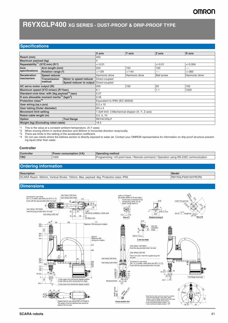
41SCARA robots
R6YXGLP400 XG SERIES - DUST-PROOF & DRIP-PROOF TYPE
Controller
Specifications
X axis Y axis Z axis R axisReach (mm) 400Maximum payload (kg) 4Repeatability*1 (XYZ:mm) (R:º)
*1 This is the value at a constant ambient temperature. (X,Y axes)
+/-0.01 +/-0.01 +/-0.004Axis specifications
Arm length (mm) 250 150 150 ----Rotation range (º) +/-129 +/-144 ---- +/-360
Deceleration mechanism
Speed reducer Harmonic drive Harmonic drive Ball screw Harmonic driveTransmission method
Motor to speed reducer Direct-coupledSpeed reducer to output Direct-coupled
AC servo motor output (W) 200 150 50 100Maximum speed (XYZ:m/sec) (R:º/sec) 6.1 1.1 1020Standard cicle time: with 2kg payload*2 (sec)
*2 When moving 25mm in vertical direction and 300mm in horizontal direction reciprocally.
0.57R axis allowable moment inertia*3 (kgm2)
*3 There are limits to the setting of the acceleration coefficient.
0.05Protection class*4
*4 Do not use robots where the bellows section is directly exposed to water jet. Contact your OMRON representative for information on drip-proof structure prevent-ing liquid other than water.
Equivalent to IP65 (IEC 60529)User wiring (sq x pcs) 0.2 x 10User tubing (Outer diameter) Ø4 x 4Movement limit setting 1.Soft limit 2.Mechanical stopper (X, Y, Z axis)Robot cable length (m) 3.5, 5, 10Option Tool flange R6YACXGLFWeight (kg) (Excluding robot cable) 18.5
Controller Power consumption (VA) Operating methodYRC 1000 Programming / I/O point trace / Remote command / Operation using RS-232C communication
Ordering information
Description ModelSCARA Reach: 400mm, Vertical Stroke: 150mm, Max. payload: 4kg, Protection class: IP65 R6YXGLP400150YRCR0
Dimensions
7.8
7.8
13.413.4 View of F
As this hole is intended for thewiring/tubing clamp, do notattach a large load to it.
4-M3 x 0.5 Depth 5(No phase relation to R-axis origin.)
• Note that the robot cannot be used at a position where the base flange, robot cable, spline, bellows, and tool flange interfere with each other in the working envelope shown above.
• X-axis mechanical stopper position: 131º• Y-axis mechanical stopper position: 146º
Widt
h ac
ross
flats:
15
Hollow
diamete
r: 11
Cross section A-A
42
16 h7 -0.0180
1010
70
User toolinstallationrange
38
Z axis tip shape
-0.0210
55
2
4
35
Detailed drawing D
E 30 h7
7±0.02
22.6
22.6
22.6
22.622.6±0.02 90
°
0+ 0.012
through-hole
View of E
4 H7
4- 4.5 through-hole
Hollow
diameter: 11
0123245587193
0326198
6
312622.5
10
Connector for user wiring(No.1 to 10 usable, cable clamp size: 13.1 to 15)
User tubing 2 ( 4 red)
User tubing 1 ( 4 black)
User tubing 4 ( 4 white)
Insert the plug provided when not used.
Cover with the caps provided when not used.
This is not used. Insert the supplied plug intothe joint. User tubing 3 ( 4 blue)
M4 ground terminal
050.5±2
65
150
D
99.5
Tool flange mount type
129°
129º
94° 94°
144°
144°
184
R156R400
307
R150
96
62
53 130
104 60
6014
0
90
212
30
10 12183 (Base size)
Connector for user wiring(No.1 to 10 usable, cable clamp size: 13.1 to 15)Cover with the caps provided when not used.
User tubing 1 ( 4 black)Insert the plug provided when not used.
User tubing 2 ( 4 red)
User tubing 3 ( 4 blue)User tubing 4 ( 4 white)
4- 9M8 bolt for installation, 4 bolts used
117F
0
167202221246
428
510
632±10
0
95.5
54.5±2
120133173
234264283
614661689
809839
44
25015056
575143 48
(150
)15
0
A A
90
Z-axis upper end mechanical stopper positionZ-axis rises by 4mm during return-to-origin
Z-axis lower end mechanical stopper position
Maximum 660during arm rotation
Maximum 190 during arm rotation
7050 20
39 101039
The weight of the tool attached here should beadded to the tip mass.
Tapped hole for user wiring 6-M3 x 0.5 Depth 6
SCARA robots
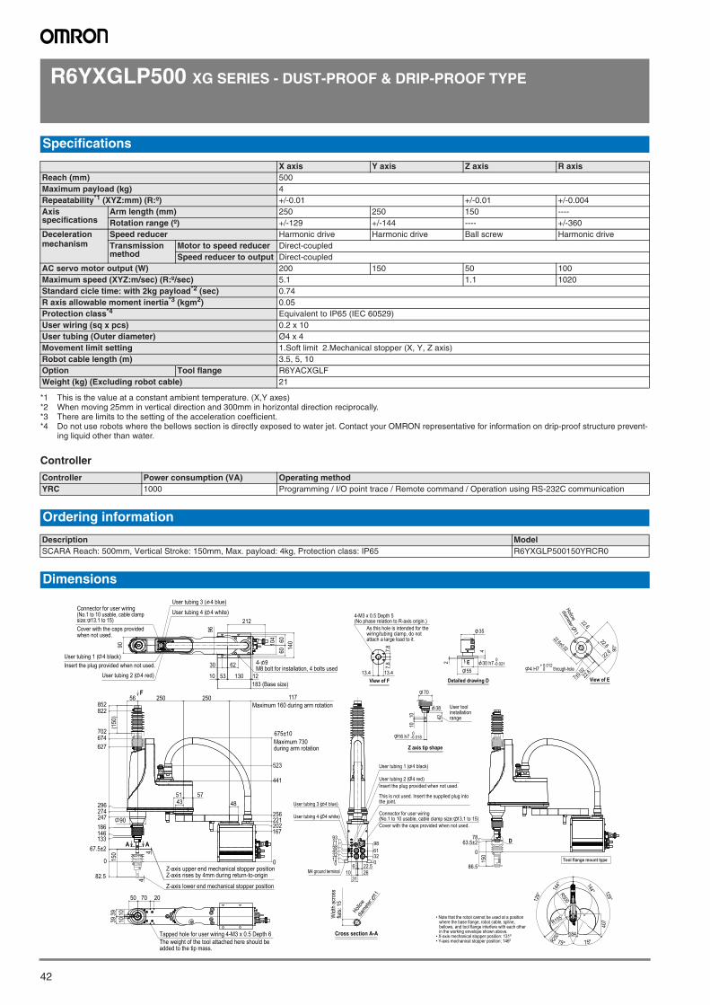
42
R6YXGLP500 XG SERIES - DUST-PROOF & DRIP-PROOF TYPE
Controller
Specifications
X axis Y axis Z axis R axisReach (mm) 500Maximum payload (kg) 4Repeatability*1 (XYZ:mm) (R:º)
*1 This is the value at a constant ambient temperature. (X,Y axes)
+/-0.01 +/-0.01 +/-0.004Axis specifications
Arm length (mm) 250 250 150 ----Rotation range (º) +/-129 +/-144 ---- +/-360
Deceleration mechanism
Speed reducer Harmonic drive Harmonic drive Ball screw Harmonic driveTransmission method
Motor to speed reducer Direct-coupledSpeed reducer to output Direct-coupled
AC servo motor output (W) 200 150 50 100Maximum speed (XYZ:m/sec) (R:º/sec) 5.1 1.1 1020Standard cicle time: with 2kg payload*2 (sec)
*2 When moving 25mm in vertical direction and 300mm in horizontal direction reciprocally.
0.74R axis allowable moment inertia*3 (kgm2)
*3 There are limits to the setting of the acceleration coefficient.
0.05Protection class*4
*4 Do not use robots where the bellows section is directly exposed to water jet. Contact your OMRON representative for information on drip-proof structure prevent-ing liquid other than water.
Equivalent to IP65 (IEC 60529)User wiring (sq x pcs) 0.2 x 10User tubing (Outer diameter) Ø4 x 4Movement limit setting 1.Soft limit 2.Mechanical stopper (X, Y, Z axis)Robot cable length (m) 3.5, 5, 10Option Tool flange R6YACXGLFWeight (kg) (Excluding robot cable) 21
Controller Power consumption (VA) Operating methodYRC 1000 Programming / I/O point trace / Remote command / Operation using RS-232C communication
Ordering information
Description ModelSCARA Reach: 500mm, Vertical Stroke: 150mm, Max. payload: 4kg, Protection class: IP65 R6YXGLP500150YRCR0
Dimensions
7.8
7.8
13.413.4 View of F
As this hole is intended for thewiring/tubing clamp, do notattach a large load to it.
4-M3 x 0.5 Depth 5(No phase relation to R-axis origin.)
• Note that the robot cannot be used at a position where the base flange, robot cable, spline, bellows, and tool flange interfere with each other in the working envelope shown above.
• X-axis mechanical stopper position: 131º• Y-axis mechanical stopper position: 146º
Widt
h ac
ross
flats:
15
Hollow
diamete
r: 11
Cross section A-A
42
16 h7 -0.0180
1010
70
User toolinstallationrange
38
Z axis tip shape
-0.0210
55
2
4
35
Detailed drawing D
E 30 h7
7±0.02
22.6
22.6
22.6
22.622.6±0.02 90
°
0+ 0.012
through-hole
View of E
4 H7
Hollow
diameter: 11
0123245587193
0326198
6
312622.5
10
Connector for user wiring(No.1 to 10 usable, cable clamp size: 13.1 to 15)
User tubing 2 ( 4 red)
User tubing 1 ( 4 black)
User tubing 4 ( 4 white)
Insert the plug provided when not used.
Cover with the caps provided when not used.
This is not used. Insert the supplied plug intothe joint. User tubing 3 ( 4 blue)
M4 ground terminal
0
86.5
63.5±278
150
D
Tool flange mount type
129°
129°
75º 75º
144° 144°
184
R155
R500
407
R250
96
62
53 130183 (Base size)
104 60
60 14090
212
30
10 12
Connector for user wiring(No.1 to 10 usable, cable clampsize: 13.1 to 15)Cover with the caps providedwhen not used.
User tubing 1 ( 4 black)Insert the plug provided when not used.
User tubing 2 ( 4 red)
User tubing 3 ( 4 blue)
User tubing 4 ( 4 white)
4- 9M8 bolt for installation, 4 bolts used
0
167202221256
441
523
675±10
0
82.5
67.5±2133146186247274296
627674702
822852
44
25025056 117
575143 48
(150
)15
0
F
90
A A
Z-axis upper end mechanical stopper positionZ-axis rises by 4mm during return-to-origin
Z-axis lower end mechanical stopper position
Maximum 730during arm rotation
Maximum 160 during arm rotation
50
1010
3939
70 20
The weight of the tool attached here should beadded to the tip mass.
Tapped hole for user wiring 4-M3 x 0.5 Depth 6
SCARA robots
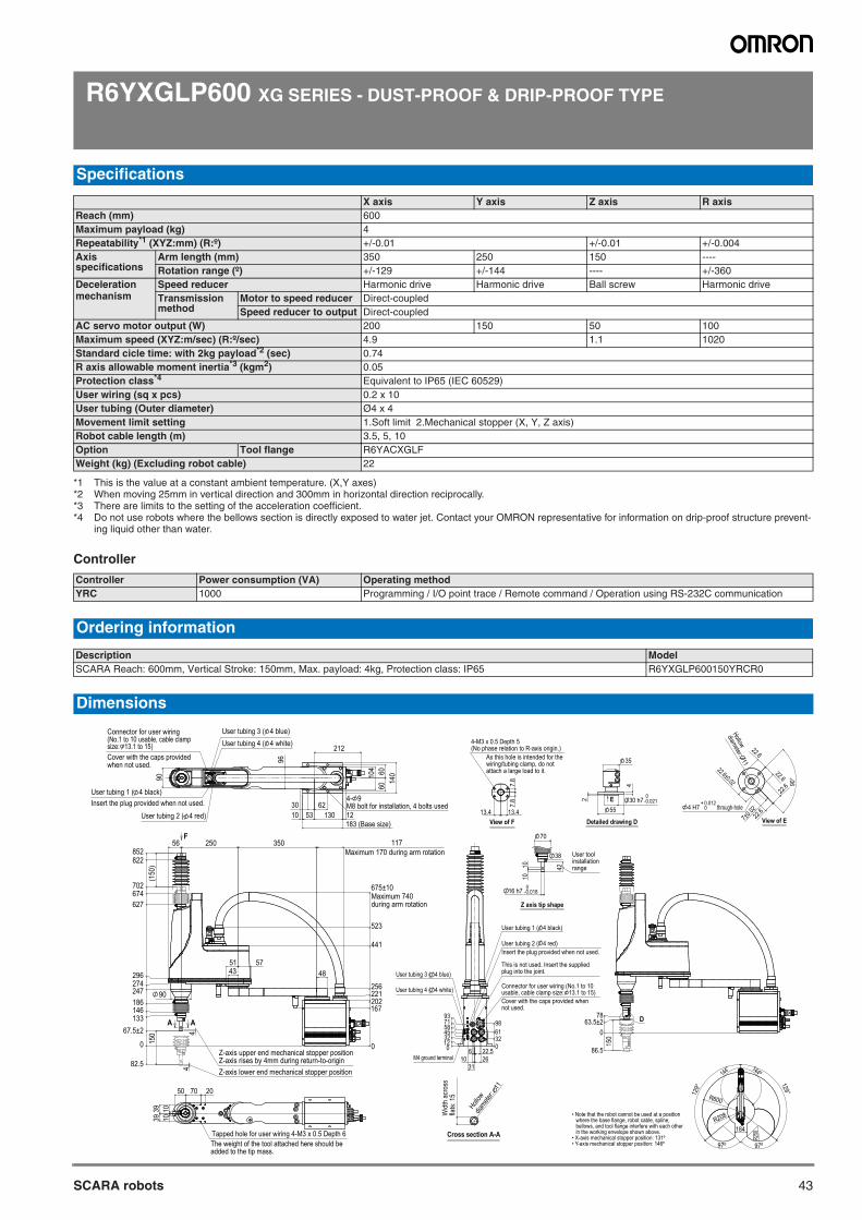
43SCARA robots
R6YXGLP600 XG SERIES - DUST-PROOF & DRIP-PROOF TYPE
Controller
Specifications
X axis Y axis Z axis R axisReach (mm) 600Maximum payload (kg) 4Repeatability*1 (XYZ:mm) (R:º)
*1 This is the value at a constant ambient temperature. (X,Y axes)
+/-0.01 +/-0.01 +/-0.004Axis specifications
Arm length (mm) 350 250 150 ----Rotation range (º) +/-129 +/-144 ---- +/-360
Deceleration mechanism
Speed reducer Harmonic drive Harmonic drive Ball screw Harmonic driveTransmission method
Motor to speed reducer Direct-coupledSpeed reducer to output Direct-coupled
AC servo motor output (W) 200 150 50 100Maximum speed (XYZ:m/sec) (R:º/sec) 4.9 1.1 1020Standard cicle time: with 2kg payload*2 (sec)
*2 When moving 25mm in vertical direction and 300mm in horizontal direction reciprocally.
0.74R axis allowable moment inertia*3 (kgm2)
*3 There are limits to the setting of the acceleration coefficient.
0.05Protection class*4
*4 Do not use robots where the bellows section is directly exposed to water jet. Contact your OMRON representative for information on drip-proof structure prevent-ing liquid other than water.
Equivalent to IP65 (IEC 60529)User wiring (sq x pcs) 0.2 x 10User tubing (Outer diameter) Ø4 x 4Movement limit setting 1.Soft limit 2.Mechanical stopper (X, Y, Z axis)Robot cable length (m) 3.5, 5, 10Option Tool flange R6YACXGLFWeight (kg) (Excluding robot cable) 22
Controller Power consumption (VA) Operating methodYRC 1000 Programming / I/O point trace / Remote command / Operation using RS-232C communication
Ordering information
Description ModelSCARA Reach: 600mm, Vertical Stroke: 150mm, Max. payload: 4kg, Protection class: IP65 R6YXGLP600150YRCR0
Dimensions
7.8
7.8
13.413.4 View of F
As this hole is intended for thewiring/tubing clamp, do notattach a large load to it.
4-M3 x 0.5 Depth 5(No phase relation to R-axis origin.)
• Note that the robot cannot be used at a position where the base flange, robot cable, spline, bellows, and tool flange interfere with each other in the working envelope shown above.
• X-axis mechanical stopper position: 131º• Y-axis mechanical stopper position: 146º
Widt
h ac
ross
flats:
15
Hollow
diamete
r: 11
Cross section A-A
42
16 h7 -0.0180
1010
70
User toolinstallationrange
38
Z axis tip shape
-0.0210
55
2
4
35
Detailed drawing D
E 30 h7
7±0.02
22.6
22.6
22.6
22.622.6±0.02 90
°
0+ 0.012
through-hole
View of E
4 H7
Hollow
diameter: 11
0123245587193
0326198
6
312622.5
10
Connector for user wiring (No.1 to 10usable, cable clamp size: 13.1 to 15)
User tubing 2 ( 4 red)
User tubing 1 ( 4 black)
User tubing 4 ( 4 white)
Insert the plug provided when not used.
Cover with the caps provided whennot used.
This is not used. Insert the suppliedplug into the joint. User tubing 3 ( 4 blue)
M4 ground terminal
0
86.5
63.5±278
150
D
129°
129°
144° 144º
97º 97º
R600
R208
184
R250
96
6253 130
183 (Base size)
104 60
6014
0
4- 9M8 bolt for installation, 4 bolts used
90
212
3010 12
Connector for user wiring(No.1 to 10 usable, cable clampsize: 13.1 to 15)Cover with the caps providedwhen not used.
User tubing 1 ( 4 black)Insert the plug provided when not used.
User tubing 2 ( 4 red)
User tubing 3 ( 4 blue)User tubing 4 ( 4 white)
0
167202221256
441
523
675±10Maximum 740during arm rotation
0
82.5
67.5±2133146186247274296
627674702
822852
44
35025056 117Maximum 170 during arm rotation
575143 48
(150
)15
0
Z-axis lower end mechanical stopper position
Z-axis upper end mechanical stopper positionZ-axis rises by 4mm during return-to-origin
F
A A
90
50
1010
3939
70 20
The weight of the tool attached here should beadded to the tip mass.
Tapped hole for user wiring 4-M3 x 0.5 Depth 6
SCARA robots
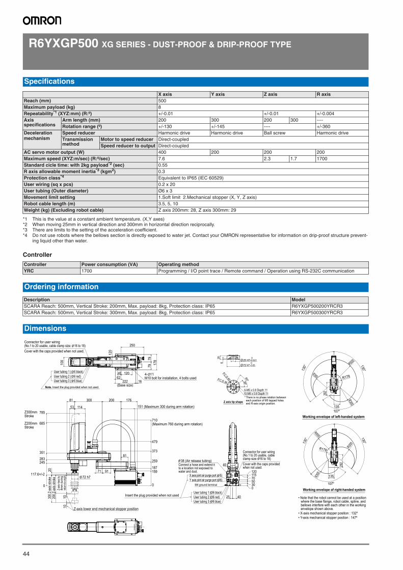
44
R6YXGP500 XG SERIES - DUST-PROOF & DRIP-PROOF TYPE
Controller
Specifications
X axis Y axis Z axis R axisReach (mm) 500Maximum payload (kg) 8Repeatability*1 (XYZ:mm) (R:º)
*1 This is the value at a constant ambient temperature. (X,Y axes)
+/-0.01 +/-0.01 +/-0.004Axis specifications
Arm length (mm) 200 300 200 300 ----Rotation range (º) +/-130 +/-145 ---- +/-360
Deceleration mechanism
Speed reducer Harmonic drive Harmonic drive Ball screw Harmonic driveTransmission method
Motor to speed reducer Direct-coupledSpeed reducer to output Direct-coupled
AC servo motor output (W) 400 200 200 200Maximum speed (XYZ:m/sec) (R:º/sec) 7.6 2.3 1.7 1700Standard cicle time: with 2kg payload*2 (sec)
*2 When moving 25mm in vertical direction and 300mm in horizontal direction reciprocally.
0.55R axis allowable moment inertia*3 (kgm2)
*3 There are limits to the setting of the acceleration coefficient.
0.3Protection class*4
*4 Do not use robots where the bellows section is directly exposed to water jet. Contact your OMRON representative for information on drip-proof structure prevent-ing liquid other than water.
Equivalent to IP65 (IEC 60529)User wiring (sq x pcs) 0.2 x 20User tubing (Outer diameter) Ø6 x 3Movement limit setting 1.Soft limit 2.Mechanical stopper (X, Y, Z axis)Robot cable length (m) 3.5, 5, 10Weight (kg) (Excluding robot cable) Z axis 200mm: 28, Z axis 300mm: 29
Controller Power consumption (VA) Operating methodYRC 1700 Programming / I/O point trace / Remote command / Operation using RS-232C communication
Ordering information
Description ModelSCARA Reach: 500mm, Vertical Stroke: 200mm, Max. payload: 8kg, Protection class: IP65 R6YXGP500200YRCR3SCARA Reach: 500mm, Vertical Stroke: 300mm, Max. payload: 8kg, Protection class: IP65 R6YXGP500300YRCR3
Dimensions
40 12062
222(Base size)
16
250
120
7979 17
8
100
User tubing 1 ( 6 black)User tubing 2 ( 6 red)User tubing 3 ( 6 blue)
Connector for user wiring(No.1 to 20 usable, cable clamp size: 16 to 18)Cover with the caps provided when not used.
4- 11M10 bolt for installation, 4 bolts used
Note. Insert the plug provided when not used.
0
159187
259
373
479
710(Maximum 760 during arm rotation)
81 176200300
53 114
685
785Z300mmStroke
Z200mmStroke
0
117.6+/-2
245283351
Z-axis
rises
by
8mm
dur
ing
return
-to-or
igin.
10200 Z
-axis
stro
ke
10
300 Z
-axis
stro
ke20
Z-axis lower end mechanical stopper position
71 91
81
72 h7
151 (Maximum 300 during arm rotation)
0305070115120
38 (Air release tubing)
User tubing 1 ( 6 black)
M4 ground terminal
X axis joint air purge port ( 6)Y axis joint air purge port ( 6)
User tubing 2 ( 6 red)User tubing 3 ( 6 blue)
Connect a hose and extend itto a location not exposed towater and dust.
4025
40
Insert the plug provided when not used
Connector for user wiring(No.1 to 20 usable, cableclamp size: 16 to 18)Cover with the caps providedwhen not used.
292
130° 130°
107°
R500
R178
R300
R300
135
Working envelope of left-handed system
107º
Working envelope of right-handed system
292
130°
130°
R500
R300
R178
R300 135
• Note that the robot cannot be used at a position where the base flange, robot cable, spline, and bellows interfere with each other in the working envelope shown above.
• X-axis mechanical stopper position : 132º• Y-axis mechanical stopper position : 147º
60ºP.C.D.36
* There is no phase relation betweeneach position of M5 tapped holesand R-axis origin position.
36º
10-M5 x 0.8 Depth 116-M5 x 0.8 Depth 11
P.C.D.60
Z axis tip shape
25 H70
+0.021
72 h70
-0.03
620
SCARA robots
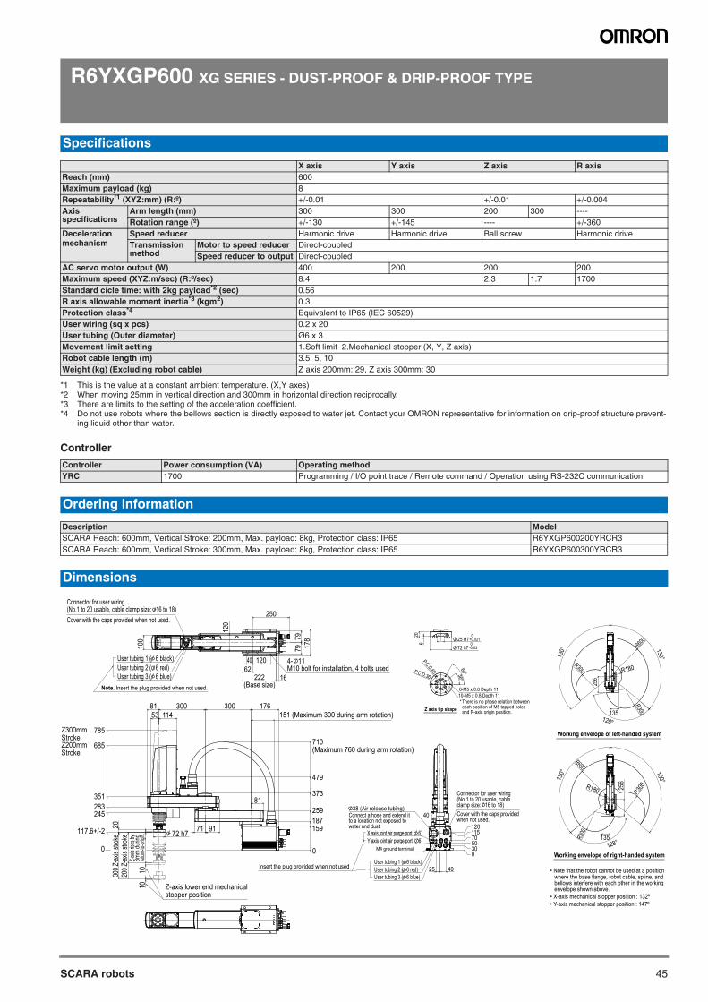
45SCARA robots
R6YXGP600 XG SERIES - DUST-PROOF & DRIP-PROOF TYPE
Controller
Specifications
X axis Y axis Z axis R axisReach (mm) 600Maximum payload (kg) 8Repeatability*1 (XYZ:mm) (R:º)
*1 This is the value at a constant ambient temperature. (X,Y axes)
+/-0.01 +/-0.01 +/-0.004Axis specifications
Arm length (mm) 300 300 200 300 ----Rotation range (º) +/-130 +/-145 ---- +/-360
Deceleration mechanism
Speed reducer Harmonic drive Harmonic drive Ball screw Harmonic driveTransmission method
Motor to speed reducer Direct-coupledSpeed reducer to output Direct-coupled
AC servo motor output (W) 400 200 200 200Maximum speed (XYZ:m/sec) (R:º/sec) 8.4 2.3 1.7 1700Standard cicle time: with 2kg payload*2 (sec)
*2 When moving 25mm in vertical direction and 300mm in horizontal direction reciprocally.
0.56R axis allowable moment inertia*3 (kgm2)
*3 There are limits to the setting of the acceleration coefficient.
0.3Protection class*4
*4 Do not use robots where the bellows section is directly exposed to water jet. Contact your OMRON representative for information on drip-proof structure prevent-ing liquid other than water.
Equivalent to IP65 (IEC 60529)User wiring (sq x pcs) 0.2 x 20User tubing (Outer diameter) Ø6 x 3Movement limit setting 1.Soft limit 2.Mechanical stopper (X, Y, Z axis)Robot cable length (m) 3.5, 5, 10Weight (kg) (Excluding robot cable) Z axis 200mm: 29, Z axis 300mm: 30
Controller Power consumption (VA) Operating methodYRC 1700 Programming / I/O point trace / Remote command / Operation using RS-232C communication
Ordering information
Description ModelSCARA Reach: 600mm, Vertical Stroke: 200mm, Max. payload: 8kg, Protection class: IP65 R6YXGP600200YRCR3SCARA Reach: 600mm, Vertical Stroke: 300mm, Max. payload: 8kg, Protection class: IP65 R6YXGP600300YRCR3
Dimensions
0305070115120
38 (Air release tubing)
User tubing 1 ( 6 black)
M4 ground terminal
X axis joint air purge port ( 6)Y axis joint air purge port ( 6)
User tubing 2 ( 6 red)User tubing 3 ( 6 blue)
Connect a hose and extend itto a location not exposed towater and dust.
4025
40
Insert the plug provided when not used
Connector for user wiring(No.1 to 20 usable, cableclamp size: 16 to 18)Cover with the caps providedwhen not used.
• Note that the robot cannot be used at a position where the base flange, robot cable, spline, and bellows interfere with each other in the working envelope shown above.
• X-axis mechanical stopper position : 132º• Y-axis mechanical stopper position : 147º
60ºP.C.D.36
* There is no phase relation betweeneach position of M5 tapped holesand R-axis origin position.
36º
10-M5 x 0.8 Depth 116-M5 x 0.8 Depth 11
P.C.D.60
Z axis tip shape
25 H70
+0.021
72 h70
-0.03
620
256
130° 130°
128º135
R300
R300
R600
R180
Working envelope of left-handed system
25613
0° 130°
128°
R600
R180 R300
R300
135
Working envelope of right-handed system
250
40 12062
120
7979 17
8
222(Base size)
16
100
Connector for user wiring(No.1 to 20 usable, cable clamp size: 16 to 18) Cover with the caps provided when not used.
User tubing 1 ( 6 black)User tubing 2 ( 6 red)User tubing 3 ( 6 blue)
4- 11M10 bolt for installation, 4 bolts used
Note. Insert the plug provided when not used.
Z-axis lower end mechanicalstopper position
0
159187259
373
479
710(Maximum 760 during arm rotation)
0
117.6+/-2
245283351
685
785
1010
71 91
81
81
72 h7
20
17630030053 114
Z300mmStrokeZ200mmStroke
200 Z
-axis
strok
e30
0 Z-ax
is str
oke
151 (Maximum 300 during arm rotation)
Z-axis
rises
by
8mm
dur
ing
return
-to-or
igin.
SCARA robots
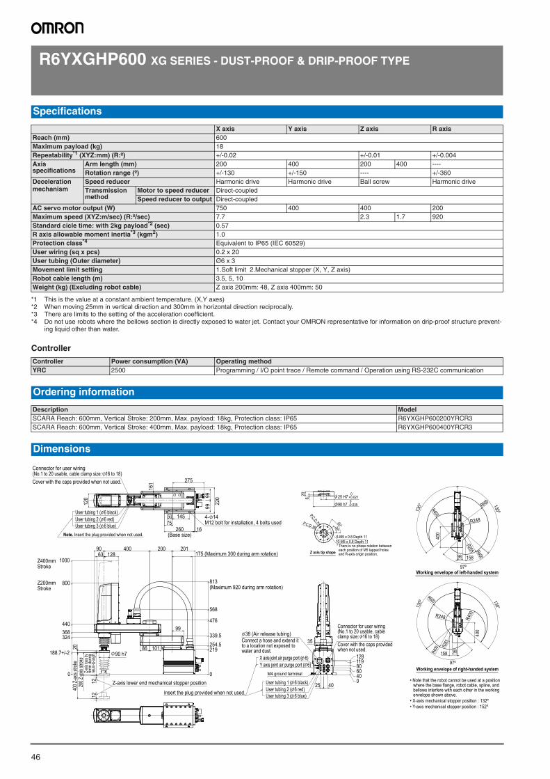
46
R6YXGHP600 XG SERIES - DUST-PROOF & DRIP-PROOF TYPE
Controller
Specifications
X axis Y axis Z axis R axisReach (mm) 600Maximum payload (kg) 18Repeatability*1 (XYZ:mm) (R:º)
*1 This is the value at a constant ambient temperature. (X,Y axes)
+/-0.02 +/-0.01 +/-0.004Axis specifications
Arm length (mm) 200 400 200 400 ----Rotation range (º) +/-130 +/-150 ---- +/-360
Deceleration mechanism
Speed reducer Harmonic drive Harmonic drive Ball screw Harmonic driveTransmission method
Motor to speed reducer Direct-coupledSpeed reducer to output Direct-coupled
AC servo motor output (W) 750 400 400 200Maximum speed (XYZ:m/sec) (R:º/sec) 7.7 2.3 1.7 920Standard cicle time: with 2kg payload*2 (sec)
*2 When moving 25mm in vertical direction and 300mm in horizontal direction reciprocally.
0.57R axis allowable moment inertia*3 (kgm2)
*3 There are limits to the setting of the acceleration coefficient.
1.0Protection class*4
*4 Do not use robots where the bellows section is directly exposed to water jet. Contact your OMRON representative for information on drip-proof structure prevent-ing liquid other than water.
Equivalent to IP65 (IEC 60529)User wiring (sq x pcs) 0.2 x 20User tubing (Outer diameter) Ø6 x 3Movement limit setting 1.Soft limit 2.Mechanical stopper (X, Y, Z axis)Robot cable length (m) 3.5, 5, 10Weight (kg) (Excluding robot cable) Z axis 200mm: 48, Z axis 400mm: 50
Controller Power consumption (VA) Operating methodYRC 2500 Programming / I/O point trace / Remote command / Operation using RS-232C communication
Ordering information
Description ModelSCARA Reach: 600mm, Vertical Stroke: 200mm, Max. payload: 18kg, Protection class: IP65 R6YXGHP600200YRCR3SCARA Reach: 600mm, Vertical Stroke: 400mm, Max. payload: 18kg, Protection class: IP65 R6YXGHP600400YRCR3
Dimensions
• Note that the robot cannot be used at a position where the base flange, robot cable, spline, and bellows interfere with each other in the working envelope shown above.
• X-axis mechanical stopper position : 132º• Y-axis mechanical stopper position : 152º
400
130° 130º
97º
R400
R248
R265
R600
98 158
R400
Working envelope of left-handed system
130º 130°
400
97º
R400
R600
R400R248
R265
98158
Working envelope of right-handed system
5075
145
275
16
9999
220
161
120
User tubing 1 ( 6 black)User tubing 2 ( 6 red)User tubing 3 ( 6 blue)
4- 14M12 bolt for installation, 4 bolts used
260(Base size)
Connector for user wiring(No.1 to 20 usable, cable clamp size: 16 to 18)Cover with the caps provided when not used.
Note. Insert the plug provided when not used.
101
90
0
219254.5339.5
476
568
813(Maximum 920 during arm rotation)
1212
0
324368440
800
1000
99
86
12863400 200 201
20
90 h7
175 (Maximum 300 during arm rotation)Z400mmStroke
Z200mmStroke
188.7+/-2
200 Z
-axis
strok
e40
0 Z-ax
is str
oke
Z-axis
rises
by 6m
m du
ring
return
-to-or
igin.
Z-axis lower end mechanical stopper position 4025
35
X axis joint air purge port ( 6)Y axis joint air purge port ( 6)
M4 ground terminal
User tubing 1 ( 6 black)User tubing 2 ( 6 red)User tubing 3 ( 6 blue)
0406080119128
Insert the plug provided when not used.
Connector for user wiring(No.1 to 20 usable, cableclamp size: 16 to 18)Cover with the caps providedwhen not used.
38 (Air release tubing)Connect a hose and extend itto a location not exposed towater and dust.
P.C.D.36
P.C.D.70
36°60°
Z axis tip shape
10-M5 x 0.8 Depth 116-M5 x 0.8 Depth 11
* There is no phase relation betweeneach position of M5 tapped holesand R-axis origin position.
620 25 H7
0+0.021
90 h70
-0.035
SCARA robots
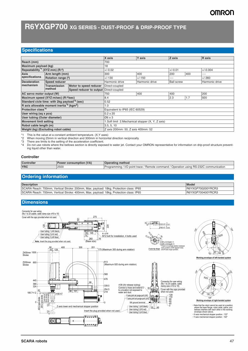
47SCARA robots
R6YXGP700 XG SERIES - DUST-PROOF & DRIP-PROOF TYPE
Controller
Specifications
X axis Y axis Z axis R axisReach (mm) 700Maximum payload (kg) 18Repeatability*1 (XYZ:mm) (R:º)
*1 This is the value at a constant ambient temperature. (X,Y axes)
+/-0.02 +/-0.01 +/-0.004Axis specifications
Arm length (mm) 300 400 200 400 ----Rotation range (º) +/-130 +/-150 ---- +/-360
Deceleration mechanism
Speed reducer Harmonic drive Harmonic drive Ball screw Harmonic driveTransmission method
Motor to speed reducer Direct-coupledSpeed reducer to output Direct-coupled
AC servo motor output (W) 750 400 400 200Maximum speed (XYZ:m/sec) (R:º/sec) 8.4 2.3 1.7 920Standard cicle time: with 2kg payload*2 (sec)
*2 When moving 25mm in vertical direction and 300mm in horizontal direction reciprocally.
0.52R axis allowable moment inertia*3 (kgm2)
*3 There are limits to the setting of the acceleration coefficient.
1.0Protection class*4
*4 Do not use robots where the bellows section is directly exposed to water jet. Contact your OMRON representative for information on drip-proof structure prevent-ing liquid other than water.
Equivalent to IP65 (IEC 60529)User wiring (sq x pcs) 0.2 x 20User tubing (Outer diameter) Ø6 x 3Movement limit setting 1.Soft limit 2.Mechanical stopper (X, Y, Z axis)Robot cable length (m) 3.5, 5, 10Weight (kg) (Excluding robot cable) Z axis 200mm: 50, Z axis 400mm: 52
Controller Power consumption (VA) Operating methodYRC 2500 Programming / I/O point trace / Remote command / Operation using RS-232C communication
Ordering information
Description ModelSCARA Reach: 700mm, Vertical Stroke: 200mm, Max. payload: 18kg, Protection class: IP65 R6YXGP700200YRCR3SCARA Reach: 700mm, Vertical Stroke: 400mm, Max. payload: 18kg, Protection class: IP65 R6YXGP700400YRCR3
Dimensions
• Note that the robot cannot be used at a position where the base flange, robot cable, spline, and bellows interfere with each other in the working envelope shown above.
• X-axis mechanical stopper position : 132º• Y-axis mechanical stopper position : 152º
4025
35
X axis joint air purge port ( 6)Y axis joint air purge port ( 6)
M4 ground terminal
User tubing 1 ( 6 black)User tubing 2 ( 6 red)User tubing 3 ( 6 blue)
0406080119128
Insert the plug provided when not used.
Connector for user wiring(No.1 to 20 usable, cableclamp size: 16 to 18)Cover with the caps providedwhen not used.
38 (Air release tubing)Connect a hose and extend itto a location not exposed towater and dust.
P.C.D.36
P.C.D.70
36°60°
Z axis tip shape
10-M5 x 0.8 Depth 116-M5 x 0.8 Depth 11
* There is no phase relation betweeneach position of M5 tapped holesand R-axis origin position.
620 25 H7
0+0.021
90 h70
-0.035
400
130°
130º
109°98 158
R400
R700
R205
R265 R400
Working envelope of left-handed system
130º
130°
400
109°
98158
R700
R400
R205
R400
R265
Working envelope of right-handed system
5075
145
275
16
9999
220
161
120
260(Base size)
Connector for user wiring(No.1 to 20 usable, cable clamp size: 16 to 18) Cover with the caps provided when not used.
User tubing 1 ( 6 black)User tubing 2 ( 6 red)User tubing 3 ( 6 blue)
4- 14M12 bolt for installation, 4 bolts used
Note. Insert the plug provided when not used.
101
90
0
219254.5339.5
476
568
813(Maximum 920 during arm rotation)
1212
0
188.7+/-2
324368440
800
1000
99
86
12863400 300 201
20
90 h7
Z400mmStroke
Z200mmStroke
175 (Maximum 300 during arm rotation)
200 Z
-axis
strok
e40
0 Z-ax
is str
oke
Z-axis
rises
by
6mm
durin
g ret
urn-to
-origin
.
Z-axis lower end mechanical stopper position
SCARA robots
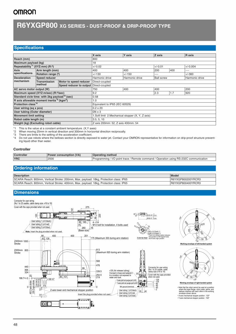
48
R6YXGP800 XG SERIES - DUST-PROOF & DRIP-PROOF TYPE
Controller
Specifications
X axis Y axis Z axis R axisReach (mm) 800Maximum payload (kg) 18Repeatability*1 (XYZ:mm) (R:º)
*1 This is the value at a constant ambient temperature. (X,Y axes)
+/-0.02 +/-0.01 +/-0.004Axis specifications
Arm length (mm) 400 400 200 400 ----Rotation range (º) +/-130 +/-150 ---- +/-360
Deceleration mechanism
Speed reducer Harmonic drive Harmonic drive Ball screw Harmonic driveTransmission method
Motor to speed reducer Direct-coupledSpeed reducer to output Direct-coupled
AC servo motor output (W) 750 400 400 200Maximum speed (XYZ:m/sec) (R:º/sec) 9.2 2.3 1.7 920Standard cicle time: with 2kg payload*2 (sec)
*2 When moving 25mm in vertical direction and 300mm in horizontal direction reciprocally.
0.58R axis allowable moment inertia*3 (kgm2)
*3 There are limits to the setting of the acceleration coefficient.
1.0Protection class*4
*4 Do not use robots where the bellows section is directly exposed to water jet. Contact your OMRON representative for information on drip-proof structure prevent-ing liquid other than water.
Equivalent to IP65 (IEC 60529)User wiring (sq x pcs) 0.2 x 20User tubing (Outer diameter) Ø6 x 3Movement limit setting 1.Soft limit 2.Mechanical stopper (X, Y, Z axis)Robot cable length (m) 3.5, 5, 10Weight (kg) (Excluding robot cable) Z axis 200mm: 52, Z axis 400mm: 54
Controller Power consumption (VA) Operating methodYRC 2500 Programming / I/O point trace / Remote command / Operation using RS-232C communication
Ordering information
Description ModelSCARA Reach: 800mm, Vertical Stroke: 200mm, Max. payload: 18kg, Protection class: IP65 R6YXGP800200YRCR3SCARA Reach: 800mm, Vertical Stroke: 400mm, Max. payload: 18kg, Protection class: IP65 R6YXGP800400YRCR3
Dimensions
• Note that the robot cannot be used at a position where the base flange, robot cable, spline, and bellows interfere with each other in the working envelope shown above.
• X-axis mechanical stopper position : 132º• Y-axis mechanical stopper position : 152º
4025
35
X axis joint air purge port ( 6)Y axis joint air purge port ( 6)
M4 ground terminal
User tubing 1 ( 6 black)User tubing 2 ( 6 red)User tubing 3 ( 6 blue)
0406080119128
Insert the plug provided when not used.
Connector for user wiring(No.1 to 20 usable, cableclamp size: 16 to 18)Cover with the caps providedwhen not used.
38 (Air release tubing)Connect a hose and extend itto a location not exposed towater and dust.
P.C.D.36
P.C.D.70
36°60°
Z axis tip shape
10-M5 x 0.8 Depth 116-M5 x 0.8 Depth 11
* There is no phase relation betweeneach position of M5 tapped holesand R-axis origin position.
620 25 H7
0+0.021
90 h70
-0.035
400
130°
119º
130°
98158
R800
R400 R205
R400
R265
Working envelope of left-handed system
400
130º
119º
130º
158
R800
R400R205
R400
R265
98
Working envelope of right-handed system
101
90
0
219254.5339.5
476
568
813(Maximum 920 during arm rotation)
1212
0
188.7+/-2
324368440
800
1000
99
86
12863400 400 201
20
90 h7
175 (Maximum 300 during arm rotation)Z400mmStroke
Z200mmStroke
200 Z
-axis
strok
e40
0 Z-ax
is str
oke
Z-axis
rises
by 6m
m du
ring
return-
to-origi
n.
Z-axis lower end mechanical stopper position
5075
145
275
16
9999
220
161
120
260(Base size)
Connector for user wiring(No.1 to 20 usable, cable clamp size: 16 to 18) Cover with the caps provided when not used.
User tubing 1 ( 6 black)User tubing 2 ( 6 red)User tubing 3 ( 6 blue)
4- 14M12 bolt for installation, 4 bolts used
Note. Insert the plug provided when not used.
SCARA robots
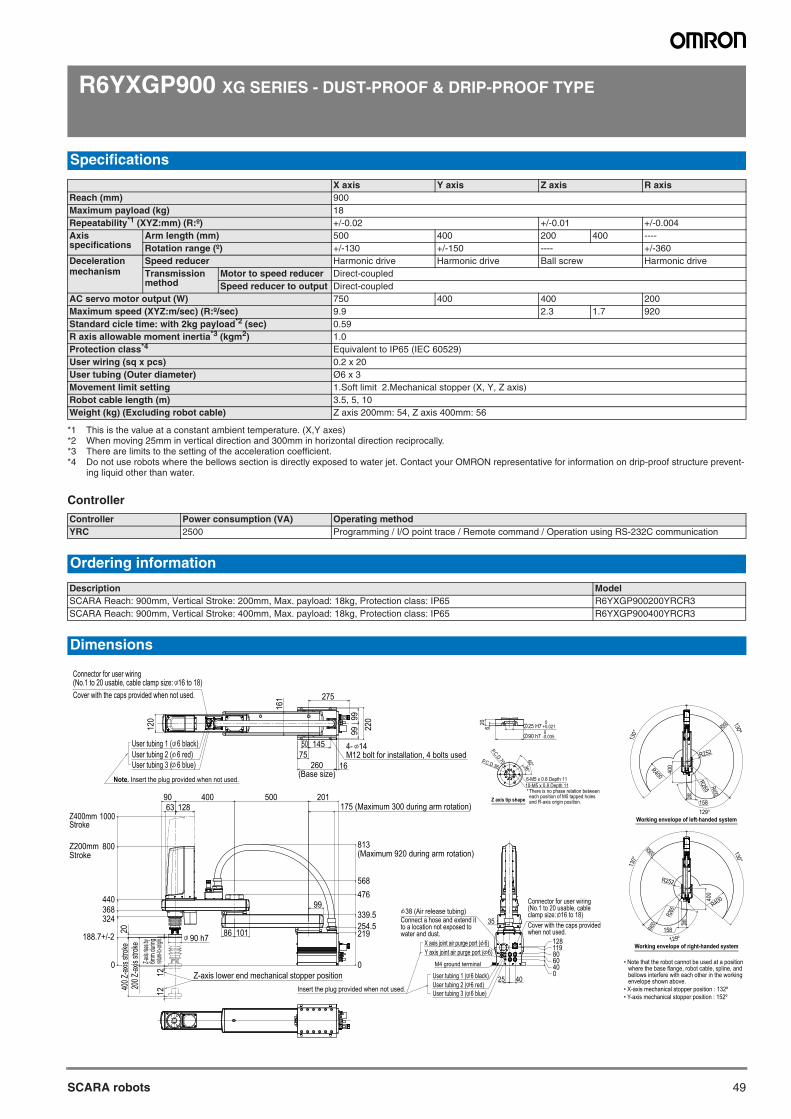
49SCARA robots
R6YXGP900 XG SERIES - DUST-PROOF & DRIP-PROOF TYPE
Controller
Specifications
X axis Y axis Z axis R axisReach (mm) 900Maximum payload (kg) 18Repeatability*1 (XYZ:mm) (R:º)
*1 This is the value at a constant ambient temperature. (X,Y axes)
+/-0.02 +/-0.01 +/-0.004Axis specifications
Arm length (mm) 500 400 200 400 ----Rotation range (º) +/-130 +/-150 ---- +/-360
Deceleration mechanism
Speed reducer Harmonic drive Harmonic drive Ball screw Harmonic driveTransmission method
Motor to speed reducer Direct-coupledSpeed reducer to output Direct-coupled
AC servo motor output (W) 750 400 400 200Maximum speed (XYZ:m/sec) (R:º/sec) 9.9 2.3 1.7 920Standard cicle time: with 2kg payload*2 (sec)
*2 When moving 25mm in vertical direction and 300mm in horizontal direction reciprocally.
0.59R axis allowable moment inertia*3 (kgm2)
*3 There are limits to the setting of the acceleration coefficient.
1.0Protection class*4
*4 Do not use robots where the bellows section is directly exposed to water jet. Contact your OMRON representative for information on drip-proof structure prevent-ing liquid other than water.
Equivalent to IP65 (IEC 60529)User wiring (sq x pcs) 0.2 x 20User tubing (Outer diameter) Ø6 x 3Movement limit setting 1.Soft limit 2.Mechanical stopper (X, Y, Z axis)Robot cable length (m) 3.5, 5, 10Weight (kg) (Excluding robot cable) Z axis 200mm: 54, Z axis 400mm: 56
Controller Power consumption (VA) Operating methodYRC 2500 Programming / I/O point trace / Remote command / Operation using RS-232C communication
Ordering information
Description ModelSCARA Reach: 900mm, Vertical Stroke: 200mm, Max. payload: 18kg, Protection class: IP65 R6YXGP900200YRCR3SCARA Reach: 900mm, Vertical Stroke: 400mm, Max. payload: 18kg, Protection class: IP65 R6YXGP900400YRCR3
Dimensions
• Note that the robot cannot be used at a position where the base flange, robot cable, spline, and bellows interfere with each other in the working envelope shown above.
• X-axis mechanical stopper position : 132º• Y-axis mechanical stopper position : 152º
4025
35
X axis joint air purge port ( 6)Y axis joint air purge port ( 6)
M4 ground terminal
User tubing 1 ( 6 black)User tubing 2 ( 6 red)User tubing 3 ( 6 blue)
0406080119128
Insert the plug provided when not used.
Connector for user wiring(No.1 to 20 usable, cableclamp size: 16 to 18)Cover with the caps providedwhen not used.
38 (Air release tubing)Connect a hose and extend itto a location not exposed towater and dust.
P.C.D.36
P.C.D.70
36°60°
Z axis tip shape
10-M5 x 0.8 Depth 116-M5 x 0.8 Depth 11
* There is no phase relation betweeneach position of M5 tapped holesand R-axis origin position.
620 25 H7
0+0.021
90 h70
-0.035
400
130°
130º
129°
98158
R900
R400
R400
R252
R265
Working envelope of left-handed system
400
129º
130°
130°
98158
R900
R400
R252
R265
R400
Working envelope of right-handed system
5075
145
275
260(Base size)
16
9999
220
161
120
Connector for user wiring(No.1 to 20 usable, cable clamp size: 16 to 18) Cover with the caps provided when not used.
User tubing 1 ( 6 black)User tubing 2 ( 6 red)User tubing 3 ( 6 blue)
4- 14M12 bolt for installation, 4 bolts used
Note. Insert the plug provided when not used.
101
90
0
219254.5339.5
476568
813(Maximum 920 during arm rotation)
1212
0
188.7+/-2
324368440
800
1000
99
86
12863400 500 201
20
90 h7
Z400mmStroke
Z200mmStroke
200 Z
-axis
strok
e40
0 Z-ax
is str
oke
175 (Maximum 300 during arm rotation)
Z-axis
rises b
y 6m
m du
ring
return-t
o-origi
n.
Z-axis lower end mechanical stopper position
SCARA robots
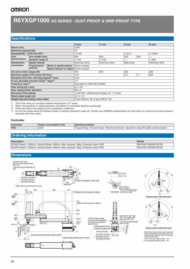
50
R6YXGP1000 XG SERIES - DUST-PROOF & DRIP-PROOF TYPE
Controller
Specifications
X axis Y axis Z axis R axisReach (mm) 1000Maximum payload (kg) 18Repeatability*1 (XYZ:mm) (R:º)
*1 This is the value at a constant ambient temperature. (X,Y axes)
+/-0.02 +/-0.01 +/-0.004Axis specifications
Arm length (mm) 600 400 200 400 ----Rotation range (º) +/-130 +/-150 ---- +/-360
Deceleration mechanism
Speed reducer Harmonic drive Harmonic drive Ball screw Harmonic driveTransmission method
Motor to speed reducer Direct-coupledSpeed reducer to output Direct-coupled
AC servo motor output (W) 750 400 400 200Maximum speed (XYZ:m/sec) (R:º/sec) 10.6 2.3 1.7 920Standard cicle time: with 2kg payload*2 (sec)
*2 When moving 25mm in vertical direction and 300mm in horizontal direction reciprocally.
0.59R axis allowable moment inertia*3 (kgm2)
*3 There are limits to the setting of the acceleration coefficient.
1.0Protection class*4
*4 Do not use robots where the bellows section is directly exposed to water jet. Contact your OMRON representative for information on drip-proof structure prevent-ing liquid other than water.
Equivalent to IP65 (IEC 60529)User wiring (sq x pcs) 0.2 x 20User tubing (Outer diameter) Ø6 x 3Movement limit setting 1.Soft limit 2.Mechanical stopper (X, Y, Z axis)Robot cable length (m) 3.5, 5, 10Weight (kg) (Excluding robot cable) Z axis 200mm: 56, Z axis 400mm: 58
Controller Power consumption (VA) Operating methodYRC 2500 Programming / I/O point trace / Remote command / Operation using RS-232C communication
Ordering information
Description ModelSCARA Reach: 1000mm, Vertical Stroke: 200mm, Max. payload: 18kg, Protection class: IP65 R6YXGP1000200YRCR3SCARA Reach: 1000mm, Vertical Stroke: 400mm, Max. payload: 18kg, Protection class: IP65 R6YXGP1000400YRCR3
Dimensions
• Note that the robot cannot be used at a position where the base flange, robot cable, spline, and bellows interfere with each other in the working envelope shown above.
• X-axis mechanical stopper position : 132º• Y-axis mechanical stopper position : 152º
4025
35
X axis joint air purge port ( 6)Y axis joint air purge port ( 6)
M4 ground terminal
User tubing 1 ( 6 black)User tubing 2 ( 6 red)User tubing 3 ( 6 blue)
0406080119128
Insert the plug provided when not used.
Connector for user wiring(No.1 to 20 usable, cableclamp size: 16 to 18)Cover with the caps providedwhen not used.
38 (Air release tubing)Connect a hose and extend itto a location not exposed towater and dust.
P.C.D.36
P.C.D.70
36°60°
Z axis tip shape
10-M5 x 0.8 Depth 116-M5 x 0.8 Depth 11
* There is no phase relation betweeneach position of M5 tapped holesand R-axis origin position.
620 25 H7
0+0.021
90 h70
-0.035
400
138°
130°
130°
98
R400
R323
R400
R1000
Working envelope of left-handed system
400
138°
130° 130°
98
R1000
R400
R400
R323
Working envelope of right-handed system
101
90
0
219254.5339.5
476
568
813(Maximum 920 during arm rotation)
1212
0
188.7+/-2
324368440
800
1000
99
86
12863400 600 201
20
90 h7
Z400mmStroke
Z200mmStroke
200 Z
-axis
strok
e40
0 Z-ax
is str
oke
175 (Maximum 300 during arm rotation)
Z-axis
rises
by 6m
m du
ring
return
-to-or
igin.
Z-axis lower end mechanical stopper position
5075
145
275
260(Base size)
16
9999
220
161
120
Note. Insert the plug provided when not used.
Connector for user wiring(No.1 to 20 usable, cable clamp size: 16 to 18)
Cover with the caps provided when notused.
User tubing 1 ( 6 black)User tubing 2 ( 6 red)User tubing 3 ( 6 blue)
4- 14M12 bolt for installation, 4 bolts used
SCARA robots
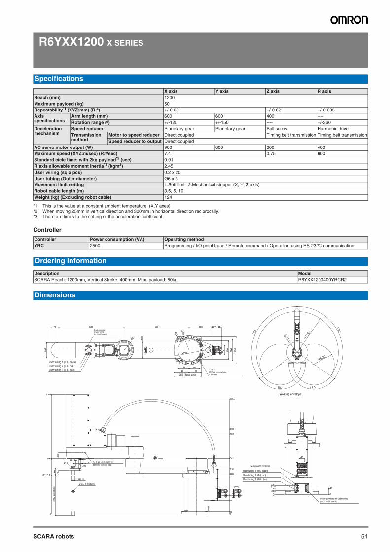
51SCARA robots
R6YXX1200 X SERIES
Controller
Specifications
X axis Y axis Z axis R axisReach (mm) 1200Maximum payload (kg) 50Repeatability*1 (XYZ:mm) (R:º)
*1 This is the value at a constant ambient temperature. (X,Y axes)
+/-0.05 +/-0.02 +/-0.005Axis specifications
Arm length (mm) 600 600 400 ----Rotation range (º) +/-125 +/-150 ---- +/-360
Deceleration mechanism
Speed reducer Planetary gear Planetary gear Ball screw Harmonic driveTransmission method
Motor to speed reducer Direct-coupled Timing belt transmission Timing belt transmissionSpeed reducer to output Direct-coupled
AC servo motor output (W) 900 800 600 400Maximum speed (XYZ:m/sec) (R:º/sec) 7.4 0.75 600Standard cicle time: with 2kg payload*2 (sec)
*2 When moving 25mm in vertical direction and 300mm in horizontal direction reciprocally.
0.91R axis allowable moment inertia*3 (kgm2)
*3 There are limits to the setting of the acceleration coefficient.
2.45User wiring (sq x pcs) 0.2 x 20User tubing (Outer diameter) Ø6 x 3Movement limit setting 1.Soft limit 2.Mechanical stopper (X, Y, Z axis)Robot cable length (m) 3.5, 5, 10Weight (kg) (Excluding robot cable) 124
Controller Power consumption (VA) Operating methodYRC 2500 Programming / I/O point trace / Remote command / Operation using RS-232C communication
Ordering information
Description ModelSCARA Reach: 1200mm, Vertical Stroke: 400mm, Max. payload: 50kg. R6YXX1200400YRCR2
Dimensions
Working envelope
User tubing 1 (Ø 6, black)
User tubing 2 (Ø 6, red)
User tubing 3 (Ø 6, blue)
252 (Base size)
D-sub connector
for user wiring
(No. 1 to 20 usable)
4- Ø 14
M12 bolt for installation,
4 bolt used
M16 × 2 Depth 25
Ø25–0.01
–0.02
2 × 2-M4 × 0.7, Depth 10
(Same for opposing side)
40
0 Z
-axi
s st
roke
D-sub connector for user wiring
(No. 1 to 20 usable)
User tubing 1 (Ø 6, black)
User tubing 2 (Ø 6, red)
User tubing 3 (Ø 6, blue)
M4 ground terminal
SCARA robots
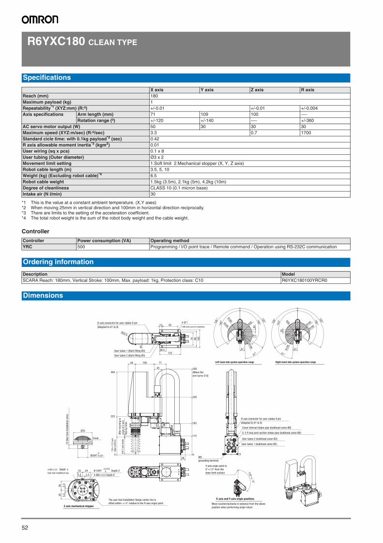
52
R6YXC180 CLEAN TYPE
Controller
Specifications
X axis Y axis Z axis R axisReach (mm) 180Maximum payload (kg) 1Repeatability*1 (XYZ:mm) (R:º)
*1 This is the value at a constant ambient temperature. (X,Y axes)
+/-0.01 +/-0.01 +/-0.004Axis specifications Arm length (mm) 71 109 100 ----
Rotation range (º) +/-120 +/-140 ---- +/-360AC servo motor output (W) 50 30 30 30Maximum speed (XYZ:m/sec) (R:º/sec) 3.3 0.7 1700Standard cicle time: with 0.1kg payload*2 (sec)
*2 When moving 25mm in vertical direction and 100mm in horizontal direction reciprocally.
0.42R axis allowable moment inertia*3 (kgm2)
*3 There are limits to the setting of the acceleration coefficient.
0.01User wiring (sq x pcs) 0.1 x 8User tubing (Outer diameter) Ø3 x 2Movement limit setting 1.Soft limit 2.Mechanical stopper (X, Y, Z axis)Robot cable length (m) 3.5, 5, 10Weight (kg) (Excluding robot cable)*4
*4 The total robot weight is the sum of the robot body weight and the cable weight.
6.5Robot cable weight 1.5kg (3.5m), 2.1kg (5m), 4.2kg (10m)Degree of cleanliness CLASS 10 (0.1 micron base)Intake air (N l/min) 30
Controller Power consumption (VA) Operating methodYRC 500 Programming / I/O point trace / Remote command / Operation using RS-232C communication
Ordering information
Description ModelSCARA Reach: 180mm, Vertical Stroke: 100mm, Max. payload: 1kg, Protection class: C10 R6YXC180100YRCR0
Dimensions
74 90 105
15 92
40.5125
R32.5
4-Ø 7
4 M6 bolts used for installation
D-sub connector for user cables 9 pin
(Adapted to #1 to 8)
64
0
223
484
100
Z ax
is s
trok
e
0
110
183
335
500
10944 71
45
28
55
12:U
ser
tool
inst
alla
tion
area
Cover
5.3 5.3
5.3
5.3
2626
16 24
4-M3 x 0.5 Depth 6
4-M3 x 0.5 Depth 6
User tool installation tapØ 10H7
+0.0150 Depth 2
Z axis mechanical stopper
D-sub connector for user cables 9 pin
(Adapted to #1 to 8)
User tubes 2 (bulkhead union Ø3)
User tubes 1 (bulkhead union Ø3)
Cover internal intake pipe (bulkhead union Ø8)
X, Y, R axis joint section intake pipe (bulkhead union Ø6)
R109
R109
R71
R30
30
R180
67
140°120°
57°
140°12
0° 120°
120° 140
°140°
57°
67R109
R71
30
R30
R180
R109
133°+/ -5°
Ø30h7 0-0.021
Left-hand side system operation range Right-hand side system operation range
User tubes 1 (Barb fitting Ø3)
User tubes 2 (Barb fitting Ø3)
X-axis and Y-axis origin positions
(When the arm turns 510)
Aft
er r
etur
ning
to
orig
in o
f Z
axis
R
ise
by 5
mm
105
+/-
2 (Z
-axi
s or
igin
pos
ition
)
The user tool installation flange center line is offset within +/-5° relative to the R axis origin point. Move counterclockwise in advance from the above
position when performing origin return.
X axis origin point is 0°+/-5° from the base front surface
M3 grounding terminal
SCARA robots
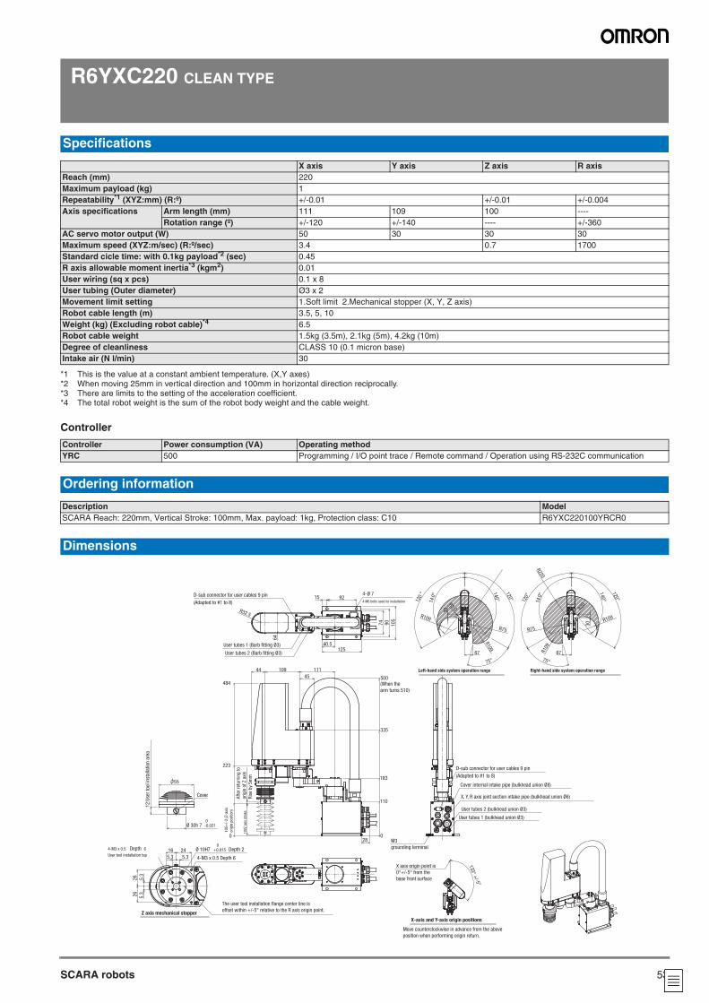
53SCARA robots
R6YXC220 CLEAN TYPE
Controller
Specifications
X axis Y axis Z axis R axisReach (mm) 220Maximum payload (kg) 1Repeatability*1 (XYZ:mm) (R:º) +/-0.01 +/-0.01 +/-0.004Axis specifications Arm length (mm) 111 109 100 ----
Rotation range (º) +/-120 +/-140 ---- +/-360AC servo motor output (W) 50 30 30 30Maximum speed (XYZ:m/sec) (R:º/sec) 3.4 0.7 1700Standard cicle time: with 0.1kg payload*2 (sec) 0.45R axis allowable moment inertia*3 (kgm2) 0.01User wiring (sq x pcs) 0.1 x 8User tubing (Outer diameter) Ø3 x 2Movement limit setting 1.Soft limit 2.Mechanical stopper (X, Y, Z axis)Robot cable length (m) 3.5, 5, 10Weight (kg) (Excluding robot cable)*4 6.5Robot cable weight 1.5kg (3.5m), 2.1kg (5m), 4.2kg (10m)Degree of cleanliness CLASS 10 (0.1 micron base)Intake air (N l/min) 30
*1 This is the value at a constant ambient temperature. (X,Y axes)*2 When moving 25mm in vertical direction and 100mm in horizontal direction reciprocally.*3 There are limits to the setting of the acceleration coefficient.*4 The total robot weight is the sum of the robot body weight and the cable weight.
Controller Power consumption (VA) Operating methodYRC 500 Programming / I/O point trace / Remote command / Operation using RS-232C communication
Ordering information
Description ModelSCARA Reach: 220mm, Vertical Stroke: 100mm, Max. payload: 1kg, Protection class: C10 R6YXC220100YRCR0
Dimensions
40.5125
R32.5
64
D-sub connector for user cables 9 pin
(Adapted to #1 to 8)
User tubes 1 (Barb fitting Ø3)
User tubes 2 (Barb fitting Ø3)
15 924-Ø 7
4 M6 bolts used for installation
74
90
10
5
223
100Z a
xis
stro
ke
0
484
0
110
183
335
500
44 109
45
111
28
55
12
:Use
r to
ol in
stal
lation
are
a
Cover
5.3 5.3
16 24
4-M3 x 0.5 Depth 6
4-M3 x 0.5 Depth 6
User tool installation tap
Ø 10H7 0
+0.015 Depth 2
5.3
5.3
26
26
Z axis mechanical stopper
D-sub connector for user cables 9 pin
(Adapted to #1 to 8)
User tubes 2 (bulkhead union Ø3)
User tubes 1 (bulkhead union Ø3)
Cover internal intake pipe (bulkhead union Ø8)
X, Y, R axis joint section intake pipe (bulkhead union Ø6)
Left-hand side system operation range
67
30
R109
R30
R109
140°
120
° 120°
140°
75°
R75
140°
120°
120°
R109
R220
R75
140°
R109
67
R30
30
75°
Right-hand side system operation range
133°+
/-5°
X-axis and Y-axis origin positions
Ø 30h 7 0-0.021
(When the
arm turns 510)
Aft
er r
eturn
ing t
o
orig
in o
f Z a
xis
Ris
e by
5m
m
105+
/-2 (
Z-a
xis
orig
in p
ositio
n)
X axis origin point is
0°+/-5° from the
base front surface
M3
grounding terminal
Move counterclockwise in advance from the above
position when performing origin return.
The user tool installation flange center line is
offset within +/-5° relative to the R axis origin point.
SCARA robots
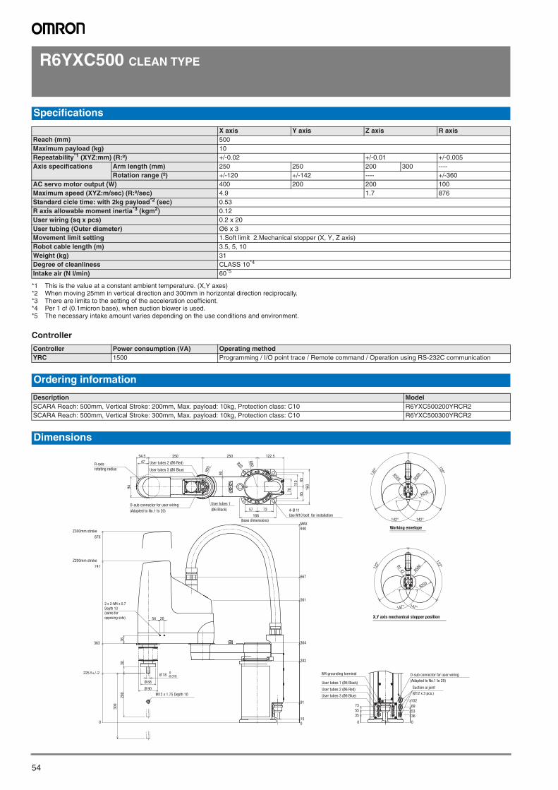
54
R6YXC500 CLEAN TYPE
Controller
Specifications
X axis Y axis Z axis R axisReach (mm) 500Maximum payload (kg) 10Repeatability*1 (XYZ:mm) (R:º)
*1 This is the value at a constant ambient temperature. (X,Y axes)
+/-0.02 +/-0.01 +/-0.005Axis specifications Arm length (mm) 250 250 200 300 ----
Rotation range (º) +/-120 +/-142 ---- +/-360AC servo motor output (W) 400 200 200 100Maximum speed (XYZ:m/sec) (R:º/sec) 4.9 1.7 876Standard cicle time: with 2kg payload*2 (sec)
*2 When moving 25mm in vertical direction and 300mm in horizontal direction reciprocally.
0.53R axis allowable moment inertia*3 (kgm2)
*3 There are limits to the setting of the acceleration coefficient.
0.12User wiring (sq x pcs) 0.2 x 20User tubing (Outer diameter) Ø6 x 3Movement limit setting 1.Soft limit 2.Mechanical stopper (X, Y, Z axis)Robot cable length (m) 3.5, 5, 10Weight (kg) 31Degree of cleanliness CLASS 10*4
*4 Per 1 cf (0.1micron base), when suction blower is used.
Intake air (N l/min) 60*5
*5 The necessary intake amount varies depending on the use conditions and environment.
Controller Power consumption (VA) Operating methodYRC 1500 Programming / I/O point trace / Remote command / Operation using RS-232C communication
Ordering information
Description ModelSCARA Reach: 500mm, Vertical Stroke: 200mm, Max. payload: 10kg, Protection class: C10 R6YXC500200YRCR2SCARA Reach: 500mm, Vertical Stroke: 300mm, Max. payload: 10kg, Protection class: C10 R6YXC500300YRCR2
Dimensions
Z200mm stroke
741
30
0
Z300mm stroke
876
200
0
363
36
225.5+/-2
30
667
561
0
282
91
M12 x 1.75 Depth 10
364
15
MAX
940
250 250 122.554.5
47
166(base dimensions)
7357
110
65
65
16
0
70
R20
R80
R55
90
54 20
94
R250
R500
120°
120
°
R163
142° 142°
122°
147°
R500
147°
122°
R250
R142
35
55
73
53
36
102
69
0 0
User tubes 2 (Ø6 Red)
User tubes 3 (Ø6 Blue)
User tubes 1
(Ø6 Black)D-sub connector for user wiring
(Adapted to No.1 to 20) 4-Ø 11
Use M10 bolt for installation
Ø 68
Ø 90
Ø 18 0-0.018
User tubes 1 (Ø6 Black)
User tubes 2 (Ø6 Red)
User tubes 3 (Ø6 Blue)
Suction ai joint
(Ø12 x 3 pcs.)
D-sub connector for user wiring
(Adapted to No.1 to 20)
M4 grounding terminal
X,Y axis mechanical stopper position
Working envelope
R-axis
rotating radius
2 x 2-M4 x 0.7
Depth 10
(same for
opposing side)
SCARA robots

55SCARA robots
R6YXC600 CLEAN TYPE
Controller
Specifications
X axis Y axis Z axis R axisReach (mm) 600Maximum payload (kg) 10Repeatability*1 (XYZ:mm) (R:º)
*1 This is the value at a constant ambient temperature. (X,Y axes)
+/-0.02 +/-0.01 +/-0.005Axis specifications Arm length (mm) 350 250 200 300 ----
Rotation range (º) +/-120 +/-145 ---- +/-360AC servo motor output (W) 400 200 200 100Maximum speed (XYZ:m/sec) (R:º/sec) 5.6 1.7 876Standard cicle time: with 2kg payload*2 (sec)
*2 When moving 25mm in vertical direction and 300mm in horizontal direction reciprocally.
0.56R axis allowable moment inertia*3 (kgm2)
*3 There are limits to the setting of the acceleration coefficient.
0.12User wiring (sq x pcs) 0.2 x 20User tubing (Outer diameter) Ø6 x 3Movement limit setting 1.Soft limit 2.Mechanical stopper (X, Y, Z axis)Robot cable length (m) 3.5, 5, 10Weight (kg) 33Degree of cleanliness CLASS 10*4
*4 Per 1 cf (0.1micron base), when suction blower is used.
Intake air (N l/min) 60*5
*5 The necessary intake amount varies depending on the use conditions and environment.
Controller Power consumption (VA) Operating methodYRC 1500 Programming / I/O point trace / Remote command / Operation using RS-232C communication
Ordering information
Description ModelSCARA Reach: 600mm, Vertical Stroke: 200mm, Max. payload: 10kg, Protection class: C10 R6YXC600200YRCR2SCARA Reach: 600mm, Vertical Stroke: 300mm, Max. payload: 10kg, Protection class: C10 R6YXC600300YRCR2
Dimensions
Z200mm stroke
741
30
0
Z300mm stroke
876
200
0
363
36
225.5+/-2
30
54 20
667.5
560.9
0
282
91
364
15
MAX940
110
65
65
16
0
70
R20
R80
R55
47
250 350 122.554.5
166
7357
90
94
R250
R600R204
120
°
145° 145°
120°
122°
14 7°
R196 R6
00
R250
122°
14 7°
0
3555
73
53
0
36
102
69
R-axis rotating radius
User tubes 2 (Ø6 Red)
User tubes 3 (Ø6 Blue)
User tubes 1
(Ø6 Black)
D-sub connector for user wiring
(Adapted to No.1 to 20)
(base dimensions)
4-Ø 11
Use M10 bolt for installation
M12 x 1.75 Depth 10
Ø 68
Ø 90
Ø 18 0-0.018 User tubes 1 (Ø6 Black)
User tubes 2 (Ø6 Red)
User tubes 3 (Ø6 Blue)
M4 grounding terminal
Suction air joint
(Ø12 x 3 pcs.)
X,Y axis mechanical stopper position
Working envelope
2 x 2-M4 x 0.7
Depth 10
(same for
opposing side)
D-sub connector for user wiring
(Adapted to No.1 to 20)
SCARA robots
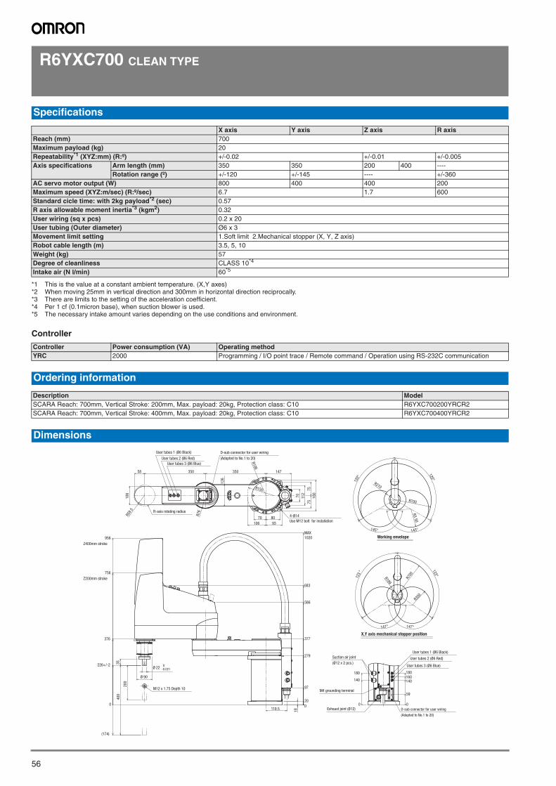
56
R6YXC700 CLEAN TYPE
Controller
Specifications
X axis Y axis Z axis R axisReach (mm) 700Maximum payload (kg) 20Repeatability*1 (XYZ:mm) (R:º)
*1 This is the value at a constant ambient temperature. (X,Y axes)
+/-0.02 +/-0.01 +/-0.005Axis specifications Arm length (mm) 350 350 200 400 ----
Rotation range (º) +/-120 +/-145 ---- +/-360AC servo motor output (W) 800 400 400 200Maximum speed (XYZ:m/sec) (R:º/sec) 6.7 1.7 600Standard cicle time: with 2kg payload*2 (sec)
*2 When moving 25mm in vertical direction and 300mm in horizontal direction reciprocally.
0.57R axis allowable moment inertia*3 (kgm2)
*3 There are limits to the setting of the acceleration coefficient.
0.32User wiring (sq x pcs) 0.2 x 20User tubing (Outer diameter) Ø6 x 3Movement limit setting 1.Soft limit 2.Mechanical stopper (X, Y, Z axis)Robot cable length (m) 3.5, 5, 10Weight (kg) 57Degree of cleanliness CLASS 10*4
*4 Per 1 cf (0.1micron base), when suction blower is used.
Intake air (N l/min) 60*5
*5 The necessary intake amount varies depending on the use conditions and environment.
Controller Power consumption (VA) Operating methodYRC 2000 Programming / I/O point trace / Remote command / Operation using RS-232C communication
Ordering information
Description ModelSCARA Reach: 700mm, Vertical Stroke: 200mm, Max. payload: 20kg, Protection class: C10 R6YXC700200YRCR2SCARA Reach: 700mm, Vertical Stroke: 400mm, Max. payload: 20kg, Protection class: C10 R6YXC700400YRCR2
Dimensions
226+/-2
0
376
756
Z200mm stroke
956
Z400mm stroke
20
0
400
(174)
35
0
20
97
279
377
586
683
119.5
MAX
1020
18
0
140
180
0
59
140160180
106
147350350
70 80
75
75
93
18
0
106
126
58
70
R106
R76
112
R59.
5
R150R150
145°
R700
R210
120°
120°
145°
R3
50
123
°
R199
R700
147° 147°
123°
R350
R-axis rotating radius
User tubes 1 (Ø6 Black)
User tubes 2 (Ø6 Red)
User tubes 3 (Ø6 Blue)
D-sub connector for user wiring
(Adapted to No.1 to 20)
4-Ø14
Use M12 bolt for installation
M12 x 1.75 Depth 10
Ø 90
Ø 22 0-0.021
Exhaust joint (Ø12) D-sub connector for user wiring
(Adapted to No.1 to 20)
M4 grounding terminal
User tubes 1 (Ø6 Black)
User tubes 2 (Ø6 Red)
User tubes 3 (Ø6 Blue)
Suction air joint
(Ø12 x 2 pcs.)
X,Y axis mechanical stopper position
Working envelope
SCARA robots
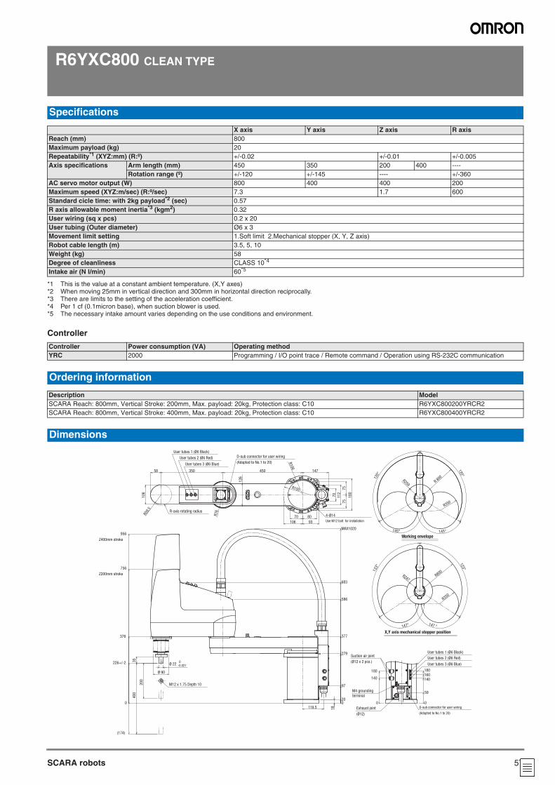
57SCARA robots
R6YXC800 CLEAN TYPE
Controller
Specifications
X axis Y axis Z axis R axisReach (mm) 800Maximum payload (kg) 20Repeatability*1 (XYZ:mm) (R:º)
*1 This is the value at a constant ambient temperature. (X,Y axes)
+/-0.02 +/-0.01 +/-0.005Axis specifications Arm length (mm) 450 350 200 400 ----
Rotation range (º) +/-120 +/-145 ---- +/-360AC servo motor output (W) 800 400 400 200Maximum speed (XYZ:m/sec) (R:º/sec) 7.3 1.7 600Standard cicle time: with 2kg payload*2 (sec)
*2 When moving 25mm in vertical direction and 300mm in horizontal direction reciprocally.
0.57R axis allowable moment inertia*3 (kgm2)
*3 There are limits to the setting of the acceleration coefficient.
0.32User wiring (sq x pcs) 0.2 x 20User tubing (Outer diameter) Ø6 x 3Movement limit setting 1.Soft limit 2.Mechanical stopper (X, Y, Z axis)Robot cable length (m) 3.5, 5, 10Weight (kg) 58Degree of cleanliness CLASS 10*4
*4 Per 1 cf (0.1micron base), when suction blower is used.
Intake air (N l/min) 60*5
*5 The necessary intake amount varies depending on the use conditions and environment.
Controller Power consumption (VA) Operating methodYRC 2000 Programming / I/O point trace / Remote command / Operation using RS-232C communication
Ordering information
Description ModelSCARA Reach: 800mm, Vertical Stroke: 200mm, Max. payload: 20kg, Protection class: C10 R6YXC800200YRCR2SCARA Reach: 800mm, Vertical Stroke: 400mm, Max. payload: 20kg, Protection class: C10 R6YXC800400YRCR2
Dimensions
35
(174)
400
200
956
Z400mm stroke
756
Z200mm stroke
376
0
226+/-2
18
MAX1020
119.5
683
586
377
279
97
200
58 350
R59.
5
106
R76
R106
126
450
106 93
8070
112
70
180
75
75
R150R150
147
R80
0
R350
145° 145°
R259
120°
120°123°
R800
R350
R247
123
°
147 °147°
180
140
0 0
59
140160180
R-axis rotating radius
User tubes 1 (Ø6 Black)
User tubes 2 (Ø6 Red)
User tubes 3 (Ø6 Blue)
D-sub connector for user wiring
(Adapted to No.1 to 20)
4-Ø14
Use M12 bolt for installation
M12 x 1.75 Depth 10
Ø 90
Ø 22 0-0.021
Exhaust joint
(Ø12)
Suction air joint
(Ø12 x 2 pcs.)
D-sub connector for user wiring
(Adapted to No.1 to 20)
User tubes 1 (Ø6 Black)
User tubes 2 (Ø6 Red)
User tubes 3 (Ø6 Blue)
X,Y axis mechanical stopper position
Working envelope
M4 grounding
terminal
SCARA robots
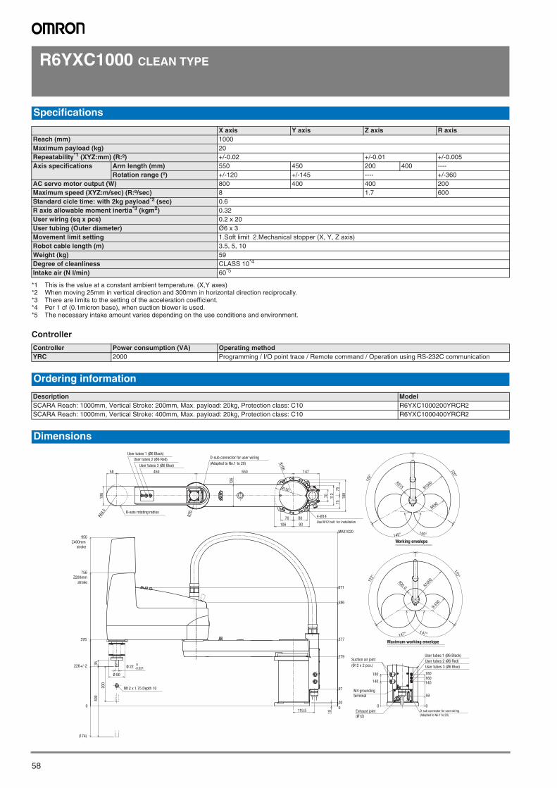
58
R6YXC1000 CLEAN TYPE
Controller
Specifications
X axis Y axis Z axis R axisReach (mm) 1000Maximum payload (kg) 20Repeatability*1 (XYZ:mm) (R:º)
*1 This is the value at a constant ambient temperature. (X,Y axes)
+/-0.02 +/-0.01 +/-0.005Axis specifications Arm length (mm) 550 450 200 400 ----
Rotation range (º) +/-120 +/-145 ---- +/-360AC servo motor output (W) 800 400 400 200Maximum speed (XYZ:m/sec) (R:º/sec) 8 1.7 600Standard cicle time: with 2kg payload*2 (sec)
*2 When moving 25mm in vertical direction and 300mm in horizontal direction reciprocally.
0.6R axis allowable moment inertia*3 (kgm2)
*3 There are limits to the setting of the acceleration coefficient.
0.32User wiring (sq x pcs) 0.2 x 20User tubing (Outer diameter) Ø6 x 3Movement limit setting 1.Soft limit 2.Mechanical stopper (X, Y, Z axis)Robot cable length (m) 3.5, 5, 10Weight (kg) 59Degree of cleanliness CLASS 10*4
*4 Per 1 cf (0.1micron base), when suction blower is used.
Intake air (N l/min) 60*5
*5 The necessary intake amount varies depending on the use conditions and environment.
Controller Power consumption (VA) Operating methodYRC 2000 Programming / I/O point trace / Remote command / Operation using RS-232C communication
Ordering information
Description ModelSCARA Reach: 1000mm, Vertical Stroke: 200mm, Max. payload: 20kg, Protection class: C10 R6YXC1000200YRCR2SCARA Reach: 1000mm, Vertical Stroke: 400mm, Max. payload: 20kg, Protection class: C10 R6YXC1000400YRCR2
Dimensions
,
35
(174)
400
200
956
Z400mm
stroke
756
Z200mm
stroke
376
0
226+/-2
18
671
586
377
279
97
20
0
MAX1020
119.5
R59.
5
112
R76
70
58
126
106
180
93
75
75
8070
450 550 147
106
R106
R150
145°
R1000
120°
120°
145°
R315
R450
147°
R300 R1
000
R450
123°
147°
123°
180
140
0 0
59
140160180
User tubes 1 (Ø6 Black)
User tubes 2 (Ø6 Red)
User tubes 3 (Ø6 Blue)
R-axis rotating radius
D-sub connector for user wiring
(Adapted to No.1 to 20)
4-Ø14
Use M12 bolt for installation
M12 x 1.75 Depth 10
Ø 90
Ø 22 0-0.021
M4 grounding
terminal
Suction air joint
(Ø12 x 2 pcs.)
D-sub connector for user wiring
(Adapted to No.1 to 20)
User tubes 1 (Ø6 Black)
User tubes 2 (Ø6 Red)
User tubes 3 (Ø6 Blue)
Working envelope
Maximum working envelope
Exhaust joint
(Ø12)
SCARA robots
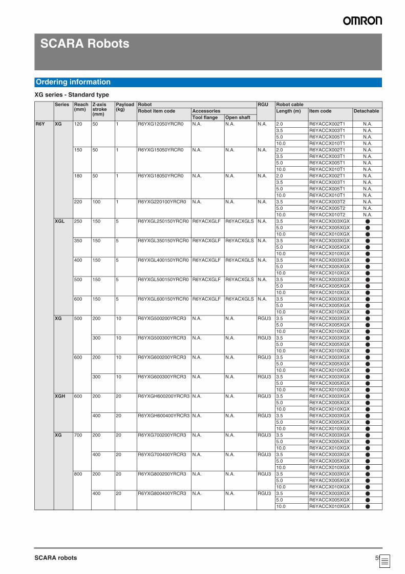
59SCARA robots
SCARA Robots
XG series - Standard type
Ordering information
Series Reach(mm)
Z-axis stroke(mm)
Payload (kg)
Robot RGU Robot cableRobot item code Accessories Length (m) Item code Detachable
Tool flange Open shaftR6Y XG 120 50 1 R6YXG12050YRCR0 N.A. N.A. N.A. 2.0 R6YACCX002T1 N.A.
3.5 R6YACCX003T1 N.A.5.0 R6YACCX005T1 N.A.10.0 R6YACCX010T1 N.A.
150 50 1 R6YXG15050YRCR0 N.A. N.A. N.A. 2.0 R6YACCX002T1 N.A.3.5 R6YACCX003T1 N.A.5.0 R6YACCX005T1 N.A.10.0 R6YACCX010T1 N.A.
180 50 1 R6YXG18050YRCR0 N.A. N.A. N.A. 2.0 R6YACCX002T1 N.A.3.5 R6YACCX003T1 N.A.5.0 R6YACCX005T1 N.A.10.0 R6YACCX010T1 N.A.
220 100 1 R6YXG220100YRCR0 N.A. N.A. N.A. 3.5 R6YACCX003T2 N.A.5.0 R6YACCX005T2 N.A.10.0 R6YACCX010T2 N.A.
XGL 250 150 5 R6YXGL250150YRCR0 R6YACXGLF R6YACXGLS N.A. 3.5 R6YACCX003XGX @
5.0 R6YACCX005XGX @
10.0 R6YACCX010XGX @
350 150 5 R6YXGL350150YRCR0 R6YACXGLF R6YACXGLS N.A. 3.5 R6YACCX003XGX @
5.0 R6YACCX005XGX @
10.0 R6YACCX010XGX @
400 150 5 R6YXGL400150YRCR0 R6YACXGLF R6YACXGLS N.A. 3.5 R6YACCX003XGX @
5.0 R6YACCX005XGX @
10.0 R6YACCX010XGX @
500 150 5 R6YXGL500150YRCR0 R6YACXGLF R6YACXGLS N.A. 3.5 R6YACCX003XGX @
5.0 R6YACCX005XGX @
10.0 R6YACCX010XGX @
600 150 5 R6YXGL600150YRCR0 R6YACXGLF R6YACXGLS N.A. 3.5 R6YACCX003XGX @
5.0 R6YACCX005XGX @
10.0 R6YACCX010XGX @
XG 500 200 10 R6YXG500200YRCR3 N.A. N.A. RGU3 3.5 R6YACCX003XGX @
5.0 R6YACCX005XGX @
10.0 R6YACCX010XGX @
300 10 R6YXG500300YRCR3 N.A. N.A. RGU3 3.5 R6YACCX003XGX @
5.0 R6YACCX005XGX @
10.0 R6YACCX010XGX @
600 200 10 R6YXG600200YRCR3 N.A. N.A. RGU3 3.5 R6YACCX003XGX @
5.0 R6YACCX005XGX @
10.0 R6YACCX010XGX @
300 10 R6YXG600300YRCR3 N.A. N.A. RGU3 3.5 R6YACCX003XGX @
5.0 R6YACCX005XGX @
10.0 R6YACCX010XGX @
XGH 600 200 20 R6YXGH600200YRCR3 N.A. N.A. RGU3 3.5 R6YACCX003XGX @
5.0 R6YACCX005XGX @
10.0 R6YACCX010XGX @
400 20 R6YXGH600400YRCR3 N.A. N.A. RGU3 3.5 R6YACCX003XGX @
5.0 R6YACCX005XGX @
10.0 R6YACCX010XGX @
XG 700 200 20 R6YXG700200YRCR3 N.A. N.A. RGU3 3.5 R6YACCX003XGX @
5.0 R6YACCX005XGX @
10.0 R6YACCX010XGX @
400 20 R6YXG700400YRCR3 N.A. N.A. RGU3 3.5 R6YACCX003XGX @
5.0 R6YACCX005XGX @
10.0 R6YACCX010XGX @
800 200 20 R6YXG800200YRCR3 N.A. N.A. RGU3 3.5 R6YACCX003XGX @
5.0 R6YACCX005XGX @
10.0 R6YACCX010XGX @
400 20 R6YXG800400YRCR3 N.A. N.A. RGU3 3.5 R6YACCX003XGX @
5.0 R6YACCX005XGX @
10.0 R6YACCX010XGX @
SCARA robotsOrdering information
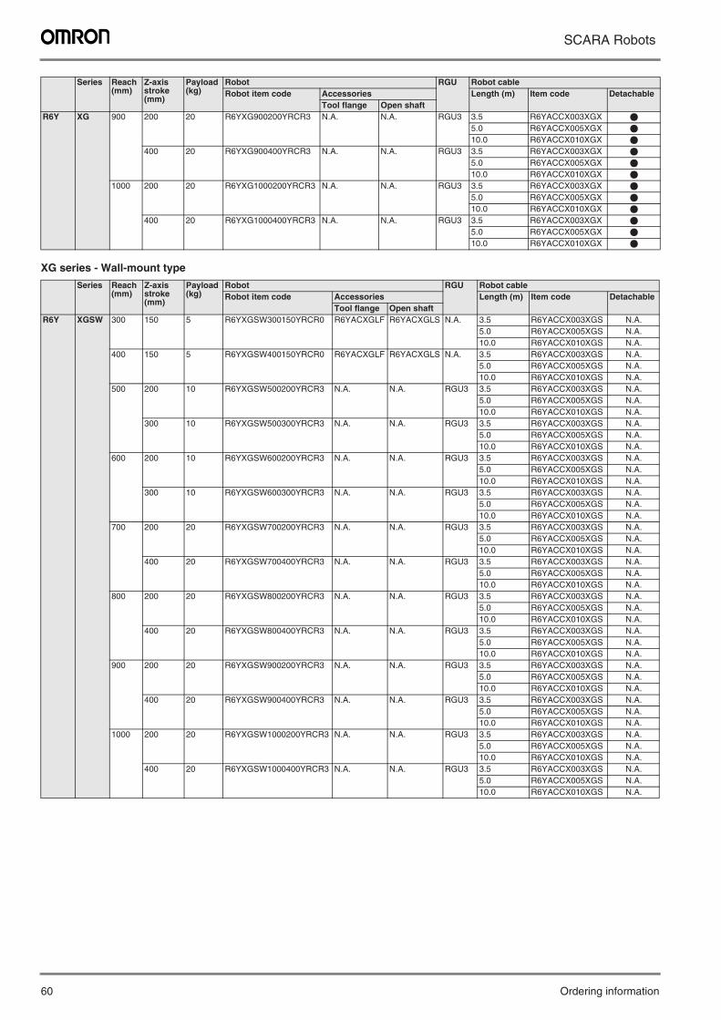
60 Ordering information
SCARA Robots
XG series - Wall-mount type
R6Y XG 900 200 20 R6YXG900200YRCR3 N.A. N.A. RGU3 3.5 R6YACCX003XGX @
5.0 R6YACCX005XGX @
10.0 R6YACCX010XGX @
400 20 R6YXG900400YRCR3 N.A. N.A. RGU3 3.5 R6YACCX003XGX @
5.0 R6YACCX005XGX @
10.0 R6YACCX010XGX @
1000 200 20 R6YXG1000200YRCR3 N.A. N.A. RGU3 3.5 R6YACCX003XGX @
5.0 R6YACCX005XGX @
10.0 R6YACCX010XGX @
400 20 R6YXG1000400YRCR3 N.A. N.A. RGU3 3.5 R6YACCX003XGX @
5.0 R6YACCX005XGX @
10.0 R6YACCX010XGX @
Series Reach(mm)
Z-axis stroke(mm)
Payload (kg)
Robot RGU Robot cableRobot item code Accessories Length (m) Item code Detachable
Tool flange Open shaftR6Y XGSW 300 150 5 R6YXGSW300150YRCR0 R6YACXGLF R6YACXGLS N.A. 3.5 R6YACCX003XGS N.A.
5.0 R6YACCX005XGS N.A.10.0 R6YACCX010XGS N.A.
400 150 5 R6YXGSW400150YRCR0 R6YACXGLF R6YACXGLS N.A. 3.5 R6YACCX003XGS N.A.5.0 R6YACCX005XGS N.A.10.0 R6YACCX010XGS N.A.
500 200 10 R6YXGSW500200YRCR3 N.A. N.A. RGU3 3.5 R6YACCX003XGS N.A.5.0 R6YACCX005XGS N.A.10.0 R6YACCX010XGS N.A.
300 10 R6YXGSW500300YRCR3 N.A. N.A. RGU3 3.5 R6YACCX003XGS N.A.5.0 R6YACCX005XGS N.A.10.0 R6YACCX010XGS N.A.
600 200 10 R6YXGSW600200YRCR3 N.A. N.A. RGU3 3.5 R6YACCX003XGS N.A.5.0 R6YACCX005XGS N.A.10.0 R6YACCX010XGS N.A.
300 10 R6YXGSW600300YRCR3 N.A. N.A. RGU3 3.5 R6YACCX003XGS N.A.5.0 R6YACCX005XGS N.A.10.0 R6YACCX010XGS N.A.
700 200 20 R6YXGSW700200YRCR3 N.A. N.A. RGU3 3.5 R6YACCX003XGS N.A.5.0 R6YACCX005XGS N.A.10.0 R6YACCX010XGS N.A.
400 20 R6YXGSW700400YRCR3 N.A. N.A. RGU3 3.5 R6YACCX003XGS N.A.5.0 R6YACCX005XGS N.A.10.0 R6YACCX010XGS N.A.
800 200 20 R6YXGSW800200YRCR3 N.A. N.A. RGU3 3.5 R6YACCX003XGS N.A.5.0 R6YACCX005XGS N.A.10.0 R6YACCX010XGS N.A.
400 20 R6YXGSW800400YRCR3 N.A. N.A. RGU3 3.5 R6YACCX003XGS N.A.5.0 R6YACCX005XGS N.A.10.0 R6YACCX010XGS N.A.
900 200 20 R6YXGSW900200YRCR3 N.A. N.A. RGU3 3.5 R6YACCX003XGS N.A.5.0 R6YACCX005XGS N.A.10.0 R6YACCX010XGS N.A.
400 20 R6YXGSW900400YRCR3 N.A. N.A. RGU3 3.5 R6YACCX003XGS N.A.5.0 R6YACCX005XGS N.A.10.0 R6YACCX010XGS N.A.
1000 200 20 R6YXGSW1000200YRCR3 N.A. N.A. RGU3 3.5 R6YACCX003XGS N.A.5.0 R6YACCX005XGS N.A.10.0 R6YACCX010XGS N.A.
400 20 R6YXGSW1000400YRCR3 N.A. N.A. RGU3 3.5 R6YACCX003XGS N.A.5.0 R6YACCX005XGS N.A.10.0 R6YACCX010XGS N.A.
Series Reach(mm)
Z-axis stroke(mm)
Payload (kg)
Robot RGU Robot cableRobot item code Accessories Length (m) Item code Detachable
Tool flange Open shaft
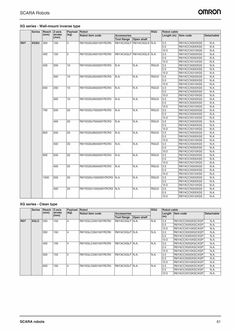
SCARA robots 61
SCARA Robots
XG series - Wall-mount inverse type
XG series - Clean type
Series Reach(mm)
Z-axis stroke(mm)
Payload (kg)
Robot RGU Robot cableRobot item code Accessories Length (m) Item code Detachable
Tool flange Open shaftR6Y XGSU 300 150 5 R6YXGSU300150YRCR0 R6YACXGLF R6YACXGLS N.A. 3.5 R6YACCX003XGS N.A.
5.0 R6YACCX005XGS N.A.10.0 R6YACCX010XGS N.A.
400 150 5 R6YXGSU400150YRCR0 R6YACXGLF R6YACXGLS N.A. 3.5 R6YACCX003XGS N.A.5.0 R6YACCX005XGS N.A.10.0 R6YACCX010XGS N.A.
500 200 10 R6YXGSU500200YRCR3 N.A. N.A. RGU3 3.5 R6YACCX003XGS N.A.5.0 R6YACCX005XGS N.A.10.0 R6YACCX010XGS N.A.
300 10 R6YXGSU500300YRCR3 N.A. N.A. RGU3 3.5 R6YACCX003XGS N.A.5.0 R6YACCX005XGS N.A.10.0 R6YACCX010XGS N.A.
600 200 10 R6YXGSU600200YRCR3 N.A. N.A. RGU3 3.5 R6YACCX003XGS N.A.5.0 R6YACCX005XGS N.A.10.0 R6YACCX010XGS N.A.
300 10 R6YXGSU600300YRCR3 N.A. N.A. RGU3 3.5 R6YACCX003XGS N.A.5.0 R6YACCX005XGS N.A.10.0 R6YACCX010XGS N.A.
700 200 20 R6YXGSU700200YRCR3 N.A. N.A. RGU3 3.5 R6YACCX003XGS N.A.5.0 R6YACCX005XGS N.A.10.0 R6YACCX010XGS N.A.
400 20 R6YXGSU700400YRCR3 N.A. N.A. RGU3 3.5 R6YACCX003XGS N.A.5.0 R6YACCX005XGS N.A.10.0 R6YACCX010XGS N.A.
800 200 20 R6YXGSU800200YRCR3 N.A. N.A. RGU3 3.5 R6YACCX003XGS N.A.5.0 R6YACCX005XGS N.A.10.0 R6YACCX010XGS N.A.
400 20 R6YXGSU800400YRCR3 N.A. N.A. RGU3 3.5 R6YACCX003XGS N.A.5.0 R6YACCX005XGS N.A.10.0 R6YACCX010XGS N.A.
900 200 20 R6YXGSU900200YRCR3 N.A. N.A. RGU3 3.5 R6YACCX003XGS N.A.5.0 R6YACCX005XGS N.A.10.0 R6YACCX010XGS N.A.
400 20 R6YXGSU900400YRCR3 N.A. N.A. RGU3 3.5 R6YACCX003XGS N.A.5.0 R6YACCX005XGS N.A.10.0 R6YACCX010XGS N.A.
1000 200 20 R6YXGSU1000200YRCR3 N.A. N.A. RGU3 3.5 R6YACCX003XGS N.A.5.0 R6YACCX005XGS N.A.10.0 R6YACCX010XGS N.A.
400 20 R6YXGSU1000400YRCR3 N.A. N.A. RGU3 3.5 R6YACCX003XGS N.A.5.0 R6YACCX005XGS N.A.10.0 R6YACCX010XGS N.A.
Series Reach(mm)
Z-axis stroke(mm)
Payload (kg)
Robot RGU Robot cableRobot item code Accessories Length
(m)Item code Detachable
Tool flange Open shaftR6Y XGLC 250 150 4 R6YXGLC250150YRCR0 R6YACXGLF N.A. N.A. 3.5 R6YACCX003XGCXGP N.A.
5.0 R6YACCX005XGCXGP N.A.10.0 R6YACCX010XGCXGP N.A.
350 150 4 R6YXGLC350150YRCR0 R6YACXGLF N.A. N.A. 3.5 R6YACCX003XGCXGP N.A.5.0 R6YACCX005XGCXGP N.A.10.0 R6YACCX010XGCXGP N.A.
400 150 4 R6YXGLC400150YRCR0 R6YACXGLF N.A. N.A. 3.5 R6YACCX003XGCXGP N.A.5.0 R6YACCX005XGCXGP N.A.10.0 R6YACCX010XGCXGP N.A.
500 150 4 R6YXGLC500150YRCR0 R6YACXGLF N.A. N.A. 3.5 R6YACCX003XGCXGP N.A.5.0 R6YACCX005XGCXGP N.A.10.0 R6YACCX010XGCXGP N.A.
600 150 4 R6YXGLC600150YRCR0 R6YACXGLF N.A. N.A. 3.5 R6YACCX003XGCXGP N.A.5.0 R6YACCX005XGCXGP N.A.10.0 R6YACCX010XGCXGP N.A.
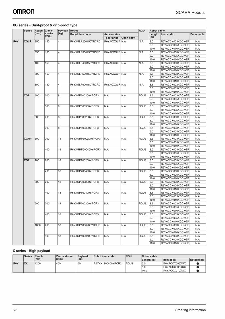
62 Ordering information
SCARA Robots
XG series - Dust-proof & drip-proof type
X series - High payload
Series Reach(mm)
Z-axis stroke(mm)
Payload (kg)
Robot RGU Robot cableRobot item code Accessories Length
(m)Item code Detachable
Tool flange Open shaftR6Y XGLP 250 150 4 R6YXGLP250150YRCR0 R6YACXGLF N.A. N.A. 3.5 R6YACCX003XGCXGP N.A.
5.0 R6YACCX005XGCXGP N.A.10.0 R6YACCX010XGCXGP N.A.
350 150 4 R6YXGLP350150YRCR0 R6YACXGLF N.A. N.A. 3.5 R6YACCX003XGCXGP N.A.5.0 R6YACCX005XGCXGP N.A.10.0 R6YACCX010XGCXGP N.A.
400 150 4 R6YXGLP400150YRCR0 R6YACXGLF N.A. N.A. 3.5 R6YACCX003XGCXGP N.A.5.0 R6YACCX005XGCXGP N.A.10.0 R6YACCX010XGCXGP N.A.
500 150 4 R6YXGLP500150YRCR0 R6YACXGLF N.A. N.A. 3.5 R6YACCX003XGCXGP N.A.5.0 R6YACCX005XGCXGP N.A.10.0 R6YACCX010XGCXGP N.A.
600 150 4 R6YXGLP600150YRCR0 R6YACXGLF N.A. N.A. 3.5 R6YACCX003XGCXGP N.A.5.0 R6YACCX005XGCXGP N.A.10.0 R6YACCX010XGCXGP N.A.
XGP 500 200 8 R6YXGP500200YRCR3 N.A. N.A. RGU3 3.5 R6YACCX003XGCXGP N.A.5.0 R6YACCX005XGCXGP N.A.10.0 R6YACCX010XGCXGP N.A.
300 8 R6YXGP500300YRCR3 N.A. N.A. RGU3 3.5 R6YACCX003XGCXGP N.A.5.0 R6YACCX005XGCXGP N.A.10.0 R6YACCX010XGCXGP N.A.
600 200 8 R6YXGP600200YRCR3 N.A. N.A. RGU3 3.5 R6YACCX003XGCXGP N.A.5.0 R6YACCX005XGCXGP N.A.10.0 R6YACCX010XGCXGP N.A.
300 8 R6YXGP600300YRCR3 N.A. N.A. RGU3 3.5 R6YACCX003XGCXGP N.A.5.0 R6YACCX005XGCXGP N.A.10.0 R6YACCX010XGCXGP N.A.
XGHP 600 200 18 R6YXGHP600200YRCR3 N.A. N.A. RGU3 3.5 R6YACCX003XGCXGP N.A.5.0 R6YACCX005XGCXGP N.A.10.0 R6YACCX010XGCXGP N.A.
400 18 R6YXGHP600400YRCR3 N.A. N.A. RGU3 3.5 R6YACCX003XGCXGP N.A.5.0 R6YACCX005XGCXGP N.A.10.0 R6YACCX010XGCXGP N.A.
XGP 700 200 18 R6YXGP700200YRCR3 N.A. N.A. RGU3 3.5 R6YACCX003XGCXGP N.A.5.0 R6YACCX005XGCXGP N.A.10.0 R6YACCX010XGCXGP N.A.
400 18 R6YXGP700400YRCR3 N.A. N.A. RGU3 3.5 R6YACCX003XGCXGP N.A.5.0 R6YACCX005XGCXGP N.A.10.0 R6YACCX010XGCXGP N.A.
800 200 18 R6YXGP800200YRCR3 N.A. N.A. RGU3 3.5 R6YACCX003XGCXGP N.A.5.0 R6YACCX005XGCXGP N.A.10.0 R6YACCX010XGCXGP N.A.
400 18 R6YXGP800400YRCR3 N.A. N.A. RGU3 3.5 R6YACCX003XGCXGP N.A.5.0 R6YACCX005XGCXGP N.A.10.0 R6YACCX010XGCXGP N.A.
900 200 18 R6YXGP900200YRCR3 N.A. N.A. RGU3 3.5 R6YACCX003XGCXGP N.A.5.0 R6YACCX005XGCXGP N.A.10.0 R6YACCX010XGCXGP N.A.
400 18 R6YXGP900400YRCR3 N.A. N.A. RGU3 3.5 R6YACCX003XGCXGP N.A.5.0 R6YACCX005XGCXGP N.A.10.0 R6YACCX010XGCXGP N.A.
1000 200 18 R6YXGP1000200YRCR3 N.A. N.A. RGU3 3.5 R6YACCX003XGCXGP N.A.5.0 R6YACCX005XGCXGP N.A.10.0 R6YACCX010XGCXGP N.A.
400 18 R6YXGP1000400YRCR3 N.A. N.A. RGU3 3.5 R6YACCX003XGCXGP N.A.5.0 R6YACCX005XGCXGP N.A.10.0 R6YACCX010XGCXGP N.A.
Series Reach(mm)
Z-axis stroke(mm)
Payload (kg)
Robot item code RGU Robot cableLength (m) Item code Detachable
R6Y XX 1200 400 50 R6YXX1200400YRCR2 RGU2 3.5 R6YACCX003XGX @
5.0 R6YACCX005XGX @
10.0 R6YACCX010XGX @
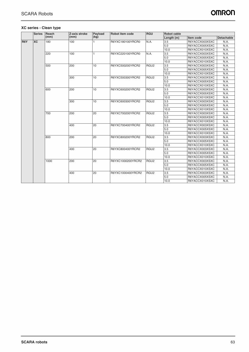
SCARA robots 63
SCARA Robots
XC series - Clean type
Series Reach(mm)
Z-axis stroke(mm)
Payload (kg)
Robot item code RGU Robot cableLength (m) Item code Detachable
R6Y XC 180 100 1 R6YXC180100YRCR0 N.A. 3.5 R6YACCX003XSXC N.A.5.0 R6YACCX005XSXC N.A.10.0 R6YACCX010XSXC N.A.
220 100 1 R6YXC220100YRCR0 N.A. 3.5 R6YACCX003XSXC N.A.5.0 R6YACCX005XSXC N.A.10.0 R6YACCX010XSXC N.A.
500 200 10 R6YXC500200YRCR2 RGU2 3.5 R6YACCX003XSXC N.A.5.0 R6YACCX005XSXC N.A.10.0 R6YACCX010XSXC N.A.
300 10 R6YXC500300YRCR2 RGU2 3.5 R6YACCX003XSXC N.A.5.0 R6YACCX005XSXC N.A.10.0 R6YACCX010XSXC N.A.
600 200 10 R6YXC600200YRCR2 RGU2 3.5 R6YACCX003XSXC N.A.5.0 R6YACCX005XSXC N.A.10.0 R6YACCX010XSXC N.A.
300 10 R6YXC600300YRCR2 RGU2 3.5 R6YACCX003XSXC N.A.5.0 R6YACCX005XSXC N.A.10.0 R6YACCX010XSXC N.A.
700 200 20 R6YXC700200YRCR2 RGU2 3.5 R6YACCX003XSXC N.A.5.0 R6YACCX005XSXC N.A.10.0 R6YACCX010XSXC N.A.
400 20 R6YXC700400YRCR2 RGU2 3.5 R6YACCX003XSXC N.A.5.0 R6YACCX005XSXC N.A.10.0 R6YACCX010XSXC N.A.
800 200 20 R6YXC800200YRCR2 RGU2 3.5 R6YACCX003XSXC N.A.5.0 R6YACCX005XSXC N.A.10.0 R6YACCX010XSXC N.A.
400 20 R6YXC800400YRCR2 RGU2 3.5 R6YACCX003XSXC N.A.5.0 R6YACCX005XSXC N.A.10.0 R6YACCX010XSXC N.A.
1000 200 20 R6YXC1000200YRCR2 RGU2 3.5 R6YACCX003XSXC N.A.5.0 R6YACCX005XSXC N.A.10.0 R6YACCX010XSXC N.A.
400 20 R6YXC1000400YRCR2 RGU2 3.5 R6YACCX003XSXC N.A.5.0 R6YACCX005XSXC N.A.10.0 R6YACCX010XSXC N.A.
64 Ordering information
SCARA Robots
In the interest of product improvement, specifications are subject to change without notice.
ALL DIMENSIONS SHOWN ARE IN MILLIMETERS.
To convert millimeters into inches, multiply by 0.03937. To convert grams into ounces, multiply by 0.03527.
Cat. No. I137E-EN-03A

![(3).pdf · uneJ Ult.l - nnnt] õunËtJ antJana 6ðUnUUVl auumnîl cuajuuvl UFlLî8U uum nm«u inan ïJunnäu SMART YRC English Program SMART YRC SMART YRC SMART YRC SMART YRC SMART](https://img.dokumen.tips/doc/110x75/5c88cbad09d3f2431b8b4d61/3pdf-unej-ultl-nnnt-ounetj-antjana-6dunuuvl-auumnil-cuajuuvl-uflli8u.jpg)


![Fish Friendly Turbines [YRC 2013]](https://img.dokumen.tips/doc/110x75/577cd3c11a28ab9e78977b87/fish-friendly-turbines-yrc-2013.jpg)