Embed Size (px)
Citation preview
Scalable 5G MPSoC Architecture
Gerhard P. Fettweis (Fellow IEEE) Vodafone Chair for Mobile Communications Systems and
Center for Advancing Electronics Dresden (cfaed), Technische Universität Dresden, Germany
Emil Matus Vodafone Chair for Mobile Communications Systems and
Center for Advancing Electronics Dresden (cfaed), Technische Universität Dresden, Germany
Abstract—The huge diversity of 5G application requirements and associated modem protocols impose high demands on radio platforms in terms of scalable latency, reliability, and computation performance. In this paper, we scope a scalable MPSoC solution that can handle a plurality of parallel sliced links. It has a core manager and a network-on-chip manager to schedule, prioritize, as well as supervise the current computations. This includes the required reliability control. Moreover, keeping the locality of data and programs under control to adhere to the required latency and low-energy constraints. Ideas sketched in this paper can form the basis to derive solutions that enable efficient low-power realizations.
Keywords—5G signal processing, Heterogeneous MPSoC, Baseband Architecture
I. INTRODUCTION The next generation cellular standards are at the verge of
deployment. Again, the maximum achievable data rate increases along “the wireless roadmap” [1], now to approach 1Gb/s at its market introduction, and growing to 10Gb/s over the coming years. When implementing the signal processing platform for these new modems, one has to distinguish between the platform required for base station processing and the mobile terminal platform. Here, we want to address the challenge of designing an multi-processor system on chip (MPSoC) which can carry out the processing tasks required.
Key part of 5G is the support for applications demanding high data rates so-called Enhanced Mobile Broadband (eMBB) [2][3]. However, 5G not only requires a linear-scale increase in required data rates and therefore processing power over 4G. Also new very low data-rate modes as CAT-M and NB-IoT (narrow-band internet-of-things) [2] have been standardized. For specific applications, the minimum data rate has been lowered to 100kb/s and below, see Fig.1. As it is very inefficient to run these low-end modem versions on a platform customized for 1-10Gb/s, a new scalability challenge arises: one must address 5 orders of magnitude in data rate scalability. As the required processing per bit at high data rates is about 10x larger due to MIMO than at low data rates, this translates into a scalability requirement of 6 orders of magnitude in signal processing power.
In addition, 5G will have a URLLC mode (ultra-reliable low latency communication) which requires very short latencies of processing in the order of 1ms and below, whereas NB-IoT requires in the order of 1s latency only. Hence, the MPSoC platform must be energy efficient for very different corner cases
of latency as well. Moreover, as URLLC requires reliability, i.e. the connection to the cellular network must not be lost, the MPSoC must also run reliably in this mode of operation as well. The status of processing as well as the network-on-chip (NoC) must be monitored continuously to ensure that the connection is not lost due to errors on the MPSoC.
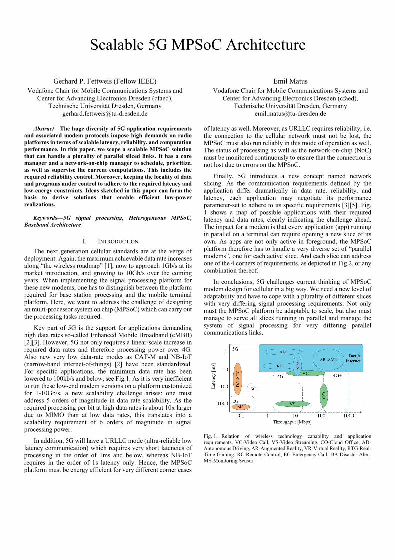
Finally, 5G introduces a new concept named network slicing. As the communication requirements defined by the application differ dramatically in data rate, reliability, and latency, each application may negotiate its performance parameter-set to adhere to its specific requirements [3][5]. Fig. 1 shows a map of possible applications with their required latency and data rates, clearly indicating the challenge ahead. The impact for a modem is that every application (app) running in parallel on a terminal can require opening a new slice of its own. As apps are not only active in foreground, the MPSoC platform therefore has to handle a very diverse set of “parallel modems”, one for each active slice. And each slice can address one of the 4 corners of requirements, as depicted in Fig.2, or any combination thereof.
In conclusions, 5G challenges current thinking of MPSoC modem design for cellular in a big way. We need a new level of adaptability and have to cope with a plurality of different slices with very differing signal processing requirements. Not only must the MPSoC platform be adaptable to scale, but also must manage to serve all slices running in parallel and manage the system of signal processing for very differing parallel communications links.
Fig. 1. Relation of wireless technology capability and application requirements. VC-Video Call, VS-Video Streaming, CO-Cloud Office, AD-Autonomous Driving, AR-Augmented Reality, VR-Virtual Reality, RTG-Real-Time Gaming, RC-Remote Control, EC-Emergency Call, DA-Disaster Alert, MS-Monitoring Sensor
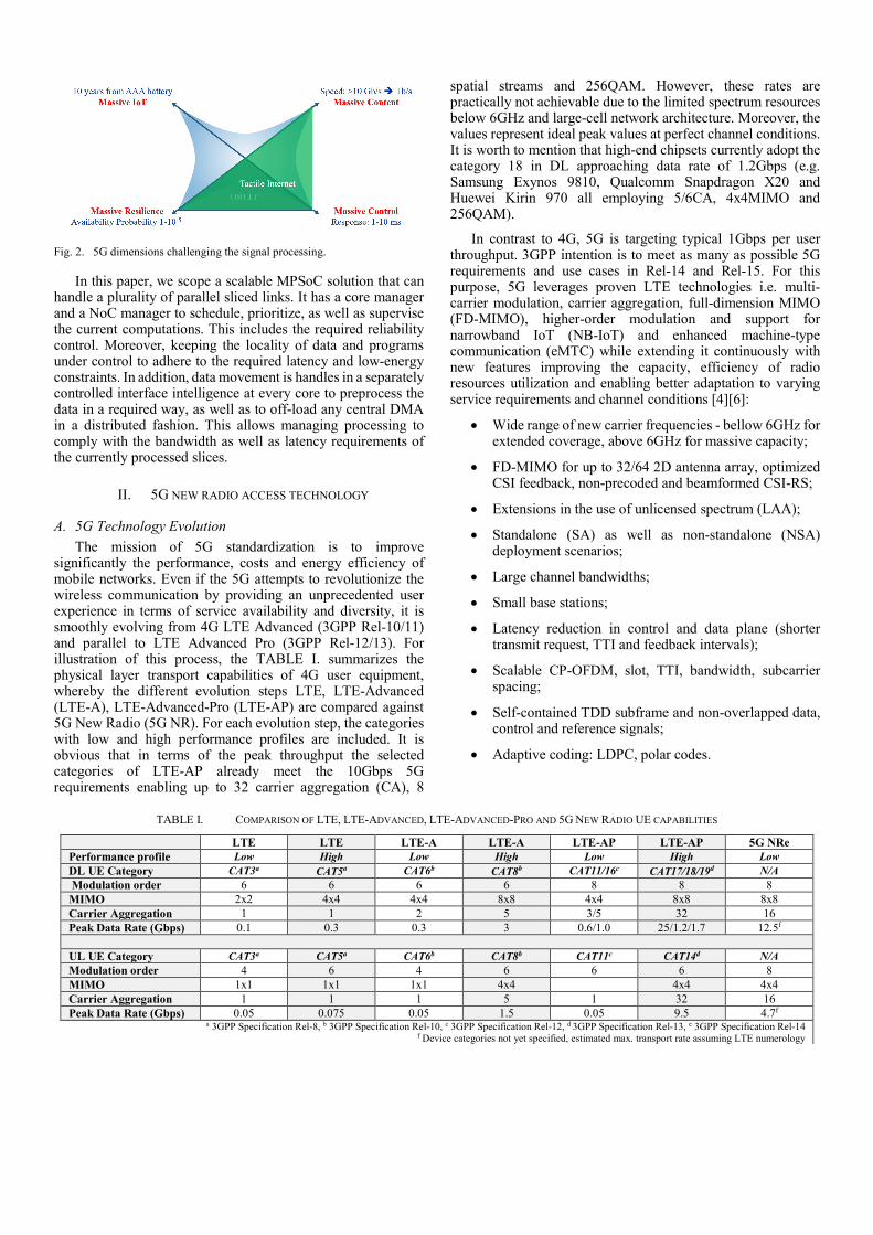
Fig. 2. 5G dimensions challenging the signal processing.
In this paper, we scope a scalable MPSoC solution that can handle a plurality of parallel sliced links. It has a core manager and a NoC manager to schedule, prioritize, as well as supervise the current computations. This includes the required reliability control. Moreover, keeping the locality of data and programs under control to adhere to the required latency and low-energy constraints. In addition, data movement is handles in a separately controlled interface intelligence at every core to preprocess the data in a required way, as well as to off-load any central DMA in a distributed fashion. This allows managing processing to comply with the bandwidth as well as latency requirements of the currently processed slices.
II. 5G NEW RADIO ACCESS TECHNOLOGY
A. 5G Technology Evolution The mission of 5G standardization is to improve
significantly the performance, costs and energy efficiency of mobile networks. Even if the 5G attempts to revolutionize the wireless communication by providing an unprecedented user experience in terms of service availability and diversity, it is smoothly evolving from 4G LTE Advanced (3GPP Rel-10/11) and parallel to LTE Advanced Pro (3GPP Rel-12/13). For illustration of this process, the TABLE I. summarizes the physical layer transport capabilities of 4G user equipment, whereby the different evolution steps LTE, LTE-Advanced (LTE-A), LTE-Advanced-Pro (LTE-AP) are compared against 5G New Radio (5G NR). For each evolution step, the categories with low and high performance profiles are included. It is obvious that in terms of the peak throughput the selected categories of LTE-AP already meet the 10Gbps 5G requirements enabling up to 32 carrier aggregation (CA), 8
spatial streams and 256QAM. However, these rates are practically not achievable due to the limited spectrum resources below 6GHz and large-cell network architecture. Moreover, the values represent ideal peak values at perfect channel conditions. It is worth to mention that high-end chipsets currently adopt the category 18 in DL approaching data rate of 1.2Gbps (e.g. Samsung Exynos 9810, Qualcomm Snapdragon X20 and Huewei Kirin 970 all employing 5/6CA, 4x4MIMO and 256QAM).
In contrast to 4G, 5G is targeting typical 1Gbps per user throughput. 3GPP intention is to meet as many as possible 5G requirements and use cases in Rel-14 and Rel-15. For this purpose, 5G leverages proven LTE technologies i.e. multi-carrier modulation, carrier aggregation, full-dimension MIMO (FD-MIMO), higher-order modulation and support for narrowband IoT (NB-IoT) and enhanced machine-type communication (eMTC) while extending it continuously with new features improving the capacity, efficiency of radio resources utilization and enabling better adaptation to varying service requirements and channel conditions [4][6]:
• Wide range of new carrier frequencies - bellow 6GHz for extended coverage, above 6GHz for massive capacity;
• FD-MIMO for up to 32/64 2D antenna array, optimized CSI feedback, non-precoded and beamformed CSI-RS;
• Extensions in the use of unlicensed spectrum (LAA);
• Standalone (SA) as well as non-standalone (NSA) deployment scenarios;
• Large channel bandwidths;
• Small base stations;
• Latency reduction in control and data plane (shorter transmit request, TTI and feedback intervals);
• Scalable CP-OFDM, slot, TTI, bandwidth, subcarrier spacing;
• Self-contained TDD subframe and non-overlapped data, control and reference signals;
• Adaptive coding: LDPC, polar codes.
TABLE I. COMPARISON OF LTE, LTE-ADVANCED, LTE-ADVANCED-PRO AND 5G NEW RADIO UE CAPABILITIES
LTE LTE LTE-A LTE-A LTE-AP LTE-AP 5G NRe Performance profile Low High Low High Low High Low DL UE Category CAT3a CAT5a CAT6b CAT8b CAT11/16c CAT17/18/19d N/A Modulation order 6 6 6 6 8 8 8 MIMO 2x2 4x4 4x4 8x8 4x4 8x8 8x8 Carrier Aggregation 1 1 2 5 3/5 32 16 Peak Data Rate (Gbps) 0.1 0.3 0.3 3 0.6/1.0 25/1.2/1.7 12.5f UL UE Category CAT3a CAT5a CAT6b CAT8b CAT11c CAT14d N/A Modulation order 4 6 4 6 6 6 8 MIMO 1x1 1x1 1x1 4x4 4x4 4x4 Carrier Aggregation 1 1 1 5 1 32 16 Peak Data Rate (Gbps) 0.05 0.075 0.05 1.5 0.05 9.5 4.7f
a 3GPP Specification Rel-8, b 3GPP Specification Rel-10, c 3GPP Specification Rel-12, d 3GPP Specification Rel-13, e 3GPP Specification Rel-14 f Device categories not yet specified, estimated max. transport rate assuming LTE numerology

In addition to already specified features in Rel-14, the following techniques are potential candidates for 5G physical layer, and as such are currently subject of investigation:
• Adaptive waveforms: Windowed-OFDM, Filtered-OFDM, FBMC/OQAM, GFDM, etc.;
• Adaptive channel structures: multiple access & channel structure according application and service requirements, mixed numerology;
• Adaptive multiple access schemes: SCMA;
• Advanced frontend: Massive MIMO, Full Duplex.
It is obvious, that above-mentioned 5G innovations will have an impact on the modem computing architecture. It is clear that the 6 orders of magnitude in signal processing performance requires far more than a rather simple “big/little” approach. Many cores must be dynamically activated as needed. Moreover, on/off and adaptive voltage/frequency scaling (incl. power gating) can lead to efficient designs, if detailed matching of baseband performance requirements is taken into account.
B. 5G Flexible Frame Structure The TABLE II. compares selected physical layer features of
4G and 5G regarding their flexibility. 4G employs fixed sub-carrier spacing (SCS) and transmission time interval (TTI) that reasonably simplifies modem design and implementation. In contrast, 5G introduces a flexible numerology and flexible TTI [7]. The constant-time constant-frequency 4G physical radio resource block is scaled using SCS factor 2n whereby the (time.frequency) product remains constant (Fig. 3). Flexible SCS enables optimizing against inter-carrier interference in the presence of Doppler spread and/or phase noise.
A flexible 5G frame structure is based on a variable length TTI comprising a variable number of slots (Fig. 4). Each slot is composed of a fixed number of OFDM symbols. Furthermore, the concept of a fractional sized mini-slot addresses the efficiency and latency requirements of transmitting short blocks of data.
Fig. 3. Illustration of scalable numerology in 5G. The 4G constant-time constant-frequency physical radio resource is scaled using SCS factor 2n. Note that number of resource elements within resource block is for illustration purpose and doesn’t reflect real configuration.
Fig. 4. Scalable 5G TTI. The 4G constant-time TTI (2 slots = 14 OFDM symbols) is transformed to variable length TTI comprising multiple slots of length 14 OFDM symbols. The example illustrates two carrier TTI structure in 4G and 5G scaling using subcarrier spacing factor 21.
The difference of 4G and 5G signal processing parameters are illustrated in Fig. 5 and TABLE III. Assuming nearly equivalent systems in terms of total bandwidth and capacity (similar density of the resource elements per sub-carrier #RE/SF), the symbol rate at the receiver is of the same order, however the sampling rate of a 5G system grows exponentially with 2𝑛𝑛+1. This fact has consequences for the design of receiver front-end and mutli-carrier demodulator.
TABLE II. COMPARISON OF OF 4G AND 5G PHYSICAL LAYER FLEXIBILITY 4G 5G NR
Carrier bandwidth (MHz) Max. 20 MHz Min. 20 @ <6GHz and 80 @ >6GHz Multicarrier Modulation DL: CP-OFDM, UL: SC-FDMA DL: CP-OFDM, UL: DFT-S-OFDMb Numerology SCS Fixed: 15kHz Flexible: 2n.15kHz; Scaling range: n={-2a,-1a,0,…,5}
Channel bandwidth/SC 100MHz / 6000SC (5CC @ 20MHz) Max. 640MHz (32CC @ 20MHz)
max. 400MHz / 3300 or 6600 SC Later: 1GHza
Data transmision Fixed TTI = 2 Slots Scalable TTI = K Slots
Slot structure Fixed 7 OFDM-Symbols Slot = {7,14}Symbols @ SCS<=60kHz and 14Symbols @ SCS>60kHz Scalable Mini-Slot = 1Symbol @ >6GHz and/or 2-({7,14}-1)Symbols
Subframe Fixed 1ms Fixed 1ms Mixed numerology No Yes - ICI mitigation by filtering/windowinga Slot/Carrier aggregation Fixed 2 / 32 Flexible / 16 Data/Control/Reference Symbols Superimposed Separated
a Feature not yet specified, subject of ongoing investigation b New multicarrier modulations are subject of ongoing investigation: Windowed-OFDM, Filtered-OFDM, Filte-Bank Multi-Carrier, General Frequency Division Multiplex
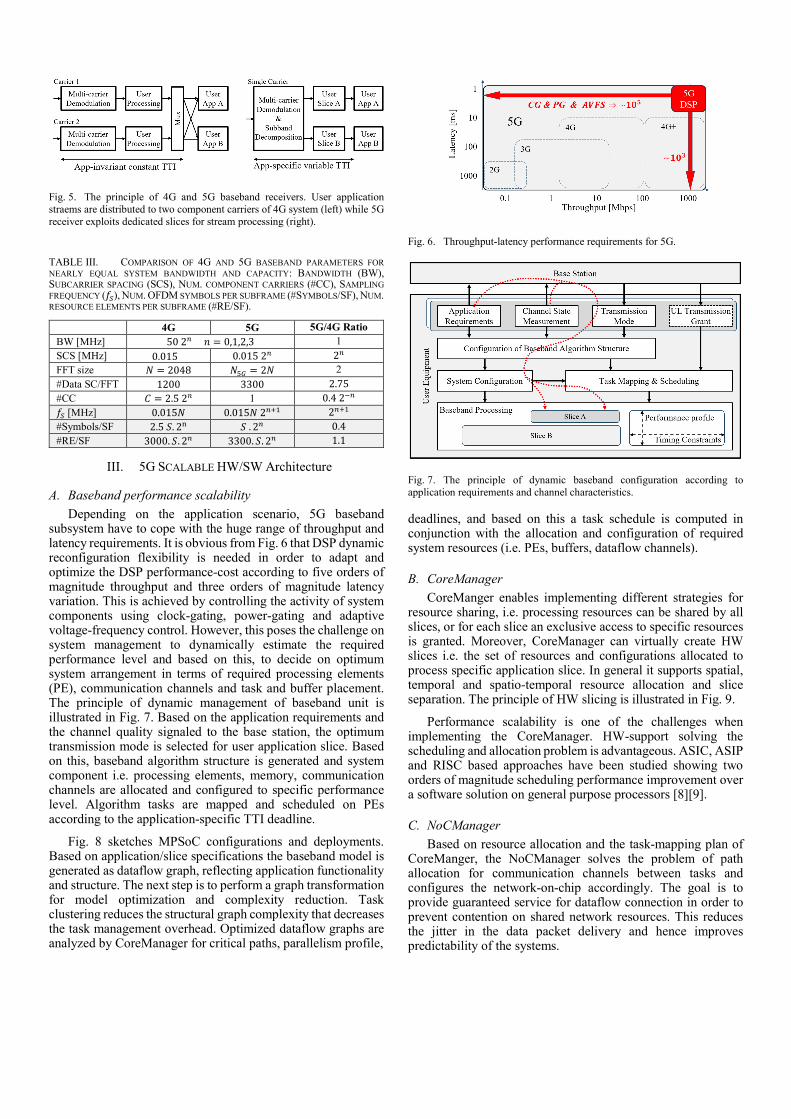
Fig. 5. The principle of 4G and 5G baseband receivers. User application straems are distributed to two component carriers of 4G system (left) while 5G receiver exploits dedicated slices for stream processing (right).
TABLE III. COMPARISON OF 4G AND 5G BASEBAND PARAMETERS FOR NEARLY EQUAL SYSTEM BANDWIDTH AND CAPACITY: BANDWIDTH (BW), SUBCARRIER SPACING (SCS), NUM. COMPONENT CARRIERS (#CC), SAMPLING FREQUENCY (𝑓𝑓𝑆𝑆), NUM. OFDM SYMBOLS PER SUBFRAME (#SYMBOLS/SF), NUM. RESOURCE ELEMENTS PER SUBFRAME (#RE/SF).
4G 5G 5G/4G Ratio BW [MHz] 50 2𝑛𝑛 𝑛𝑛 = 0,1,2,3 1 SCS [MHz] 0.015 0.015 2𝑛𝑛 2𝑛𝑛 FFT size 𝑁𝑁 = 2048 𝑁𝑁5𝐺𝐺 = 2𝑁𝑁 2 #Data SC/FFT 1200 3300 2.75 #CC 𝐶𝐶 = 2.5 2𝑛𝑛 1 0.4 2−𝑛𝑛 𝑓𝑓𝑆𝑆 [MHz] 0.015𝑁𝑁 0.015𝑁𝑁 2𝑛𝑛+1 2𝑛𝑛+1 #Symbols/SF 2.5 𝑆𝑆. 2n 𝑆𝑆 . 2𝑛𝑛 0.4 #RE/SF 3000. 𝑆𝑆. 2𝑛𝑛 3300. 𝑆𝑆. 2𝑛𝑛 1.1
III. 5G SCALABLE HW/SW Architecture
A. Baseband performance scalability Depending on the application scenario, 5G baseband
subsystem have to cope with the huge range of throughput and latency requirements. It is obvious from Fig. 6 that DSP dynamic reconfiguration flexibility is needed in order to adapt and optimize the DSP performance-cost according to five orders of magnitude throughput and three orders of magnitude latency variation. This is achieved by controlling the activity of system components using clock-gating, power-gating and adaptive voltage-frequency control. However, this poses the challenge on system management to dynamically estimate the required performance level and based on this, to decide on optimum system arrangement in terms of required processing elements (PE), communication channels and task and buffer placement. The principle of dynamic management of baseband unit is illustrated in Fig. 7. Based on the application requirements and the channel quality signaled to the base station, the optimum transmission mode is selected for user application slice. Based on this, baseband algorithm structure is generated and system component i.e. processing elements, memory, communication channels are allocated and configured to specific performance level. Algorithm tasks are mapped and scheduled on PEs according to the application-specific TTI deadline.
Fig. 8 sketches MPSoC configurations and deployments. Based on application/slice specifications the baseband model is generated as dataflow graph, reflecting application functionality and structure. The next step is to perform a graph transformation for model optimization and complexity reduction. Task clustering reduces the structural graph complexity that decreases the task management overhead. Optimized dataflow graphs are analyzed by CoreManager for critical paths, parallelism profile,
Fig. 6. Throughput-latency performance requirements for 5G.
Fig. 7. The principle of dynamic baseband configuration according to application requirements and channel characteristics.
deadlines, and based on this a task schedule is computed in conjunction with the allocation and configuration of required system resources (i.e. PEs, buffers, dataflow channels).
B. CoreManager CoreManger enables implementing different strategies for
resource sharing, i.e. processing resources can be shared by all slices, or for each slice an exclusive access to specific resources is granted. Moreover, CoreManager can virtually create HW slices i.e. the set of resources and configurations allocated to process specific application slice. In general it supports spatial, temporal and spatio-temporal resource allocation and slice separation. The principle of HW slicing is illustrated in Fig. 9.
Performance scalability is one of the challenges when implementing the CoreManager. HW-support solving the scheduling and allocation problem is advantageous. ASIC, ASIP and RISC based approaches have been studied showing two orders of magnitude scheduling performance improvement over a software solution on general purpose processors [8][9].
C. NoCManager Based on resource allocation and the task-mapping plan of
CoreManger, the NoCManager solves the problem of path allocation for communication channels between tasks and configures the network-on-chip accordingly. The goal is to provide guaranteed service for dataflow connection in order to prevent contention on shared network resources. This reduces the jitter in the data packet delivery and hence improves predictability of the systems.
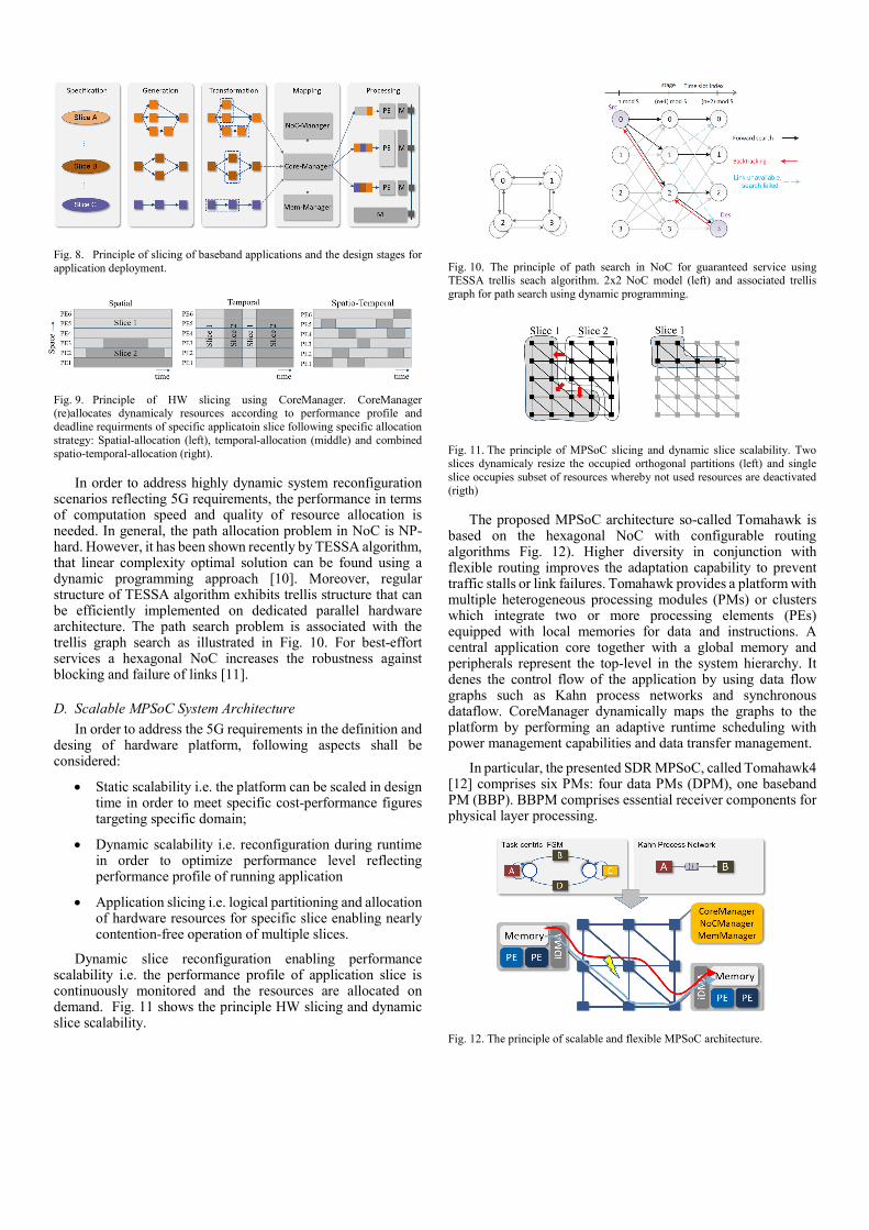
Fig. 8. Principle of slicing of baseband applications and the design stages for application deployment.
Fig. 9. Principle of HW slicing using CoreManager. CoreManager (re)allocates dynamicaly resources according to performance profile and deadline requirments of specific applicatoin slice following specific allocation strategy: Spatial-allocation (left), temporal-allocation (middle) and combined spatio-temporal-allocation (right).
In order to address highly dynamic system reconfiguration scenarios reflecting 5G requirements, the performance in terms of computation speed and quality of resource allocation is needed. In general, the path allocation problem in NoC is NP-hard. However, it has been shown recently by TESSA algorithm, that linear complexity optimal solution can be found using a dynamic programming approach [10]. Moreover, regular structure of TESSA algorithm exhibits trellis structure that can be efficiently implemented on dedicated parallel hardware architecture. The path search problem is associated with the trellis graph search as illustrated in Fig. 10. For best-effort services a hexagonal NoC increases the robustness against blocking and failure of links [11].
D. Scalable MPSoC System Architecture In order to address the 5G requirements in the definition and
desing of hardware platform, following aspects shall be considered:
• Static scalability i.e. the platform can be scaled in design time in order to meet specific cost-performance figures targeting specific domain;
• Dynamic scalability i.e. reconfiguration during runtime in order to optimize performance level reflecting performance profile of running application
• Application slicing i.e. logical partitioning and allocation of hardware resources for specific slice enabling nearly contention-free operation of multiple slices.
Dynamic slice reconfiguration enabling performance scalability i.e. the performance profile of application slice is continuously monitored and the resources are allocated on demand. Fig. 11 shows the principle HW slicing and dynamic slice scalability.
Fig. 10. The principle of path search in NoC for guaranteed service using TESSA trellis seach algorithm. 2x2 NoC model (left) and associated trellis graph for path search using dynamic programming.
Fig. 11. The principle of MPSoC slicing and dynamic slice scalability. Two slices dynamicaly resize the occupied orthogonal partitions (left) and single slice occupies subset of resources whereby not used resources are deactivated (rigth)
The proposed MPSoC architecture so-called Tomahawk is based on the hexagonal NoC with configurable routing algorithms Fig. 12). Higher diversity in conjunction with flexible routing improves the adaptation capability to prevent traffic stalls or link failures. Tomahawk provides a platform with multiple heterogeneous processing modules (PMs) or clusters which integrate two or more processing elements (PEs) equipped with local memories for data and instructions. A central application core together with a global memory and peripherals represent the top-level in the system hierarchy. It denes the control flow of the application by using data flow graphs such as Kahn process networks and synchronous dataflow. CoreManager dynamically maps the graphs to the platform by performing an adaptive runtime scheduling with power management capabilities and data transfer management.
In particular, the presented SDR MPSoC, called Tomahawk4 [12] comprises six PMs: four data PMs (DPM), one baseband PM (BBP). BBPM comprises essential receiver components for physical layer processing.
Fig. 12. The principle of scalable and flexible MPSoC architecture.
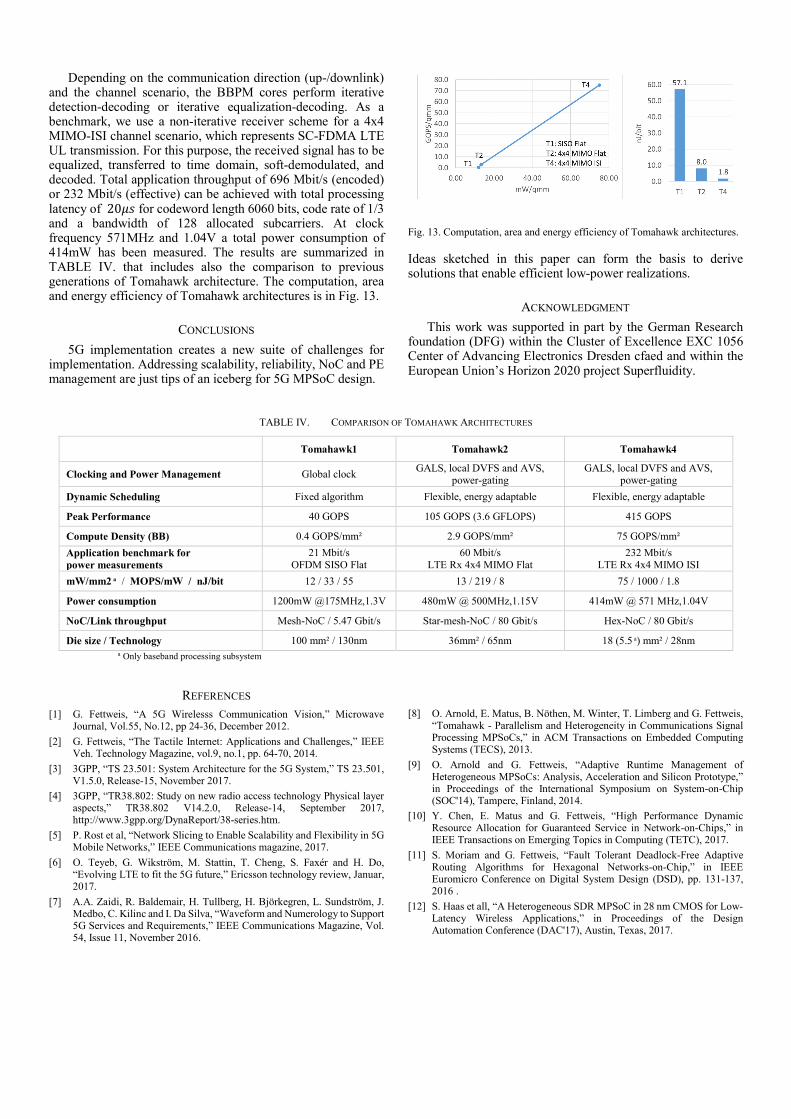
Depending on the communication direction (up-/downlink) and the channel scenario, the BBPM cores perform iterative detection-decoding or iterative equalization-decoding. As a benchmark, we use a non-iterative receiver scheme for a 4x4 MIMO-ISI channel scenario, which represents SC-FDMA LTE UL transmission. For this purpose, the received signal has to be equalized, transferred to time domain, soft-demodulated, and decoded. Total application throughput of 696 Mbit/s (encoded) or 232 Mbit/s (effective) can be achieved with total processing latency of 20𝜇𝜇𝜇𝜇 for codeword length 6060 bits, code rate of 1/3 and a bandwidth of 128 allocated subcarriers. At clock frequency 571MHz and 1.04V a total power consumption of 414mW has been measured. The results are summarized in TABLE IV. that includes also the comparison to previous generations of Tomahawk architecture. The computation, area and energy efficiency of Tomahawk architectures is in Fig. 13.
CONCLUSIONS 5G implementation creates a new suite of challenges for
implementation. Addressing scalability, reliability, NoC and PE management are just tips of an iceberg for 5G MPSoC design.
Fig. 13. Computation, area and energy efficiency of Tomahawk architectures.
Ideas sketched in this paper can form the basis to derive solutions that enable efficient low-power realizations.
ACKNOWLEDGMENT This work was supported in part by the German Research
foundation (DFG) within the Cluster of Excellence EXC 1056 Center of Advancing Electronics Dresden cfaed and within the European Union’s Horizon 2020 project Superfluidity.
TABLE IV. COMPARISON OF TOMAHAWK ARCHITECTURES
Tomahawk1 Tomahawk2 Tomahawk4
Clocking and Power Management Global clock GALS, local DVFS and AVS, power-gating
GALS, local DVFS and AVS, power-gating
Dynamic Scheduling Fixed algorithm Flexible, energy adaptable Flexible, energy adaptable
Peak Performance 40 GOPS 105 GOPS (3.6 GFLOPS) 415 GOPS
Compute Density (BB) 0.4 GOPS/mm² 2.9 GOPS/mm² 75 GOPS/mm² Application benchmark for power measurements
21 Mbit/s OFDM SISO Flat
60 Mbit/s LTE Rx 4x4 MIMO Flat
232 Mbit/s LTE Rx 4x4 MIMO ISI
mW/mm2 a / MOPS/mW / nJ/bit 12 / 33 / 55 13 / 219 / 8 75 / 1000 / 1.8
Power consumption 1200mW @175MHz,1.3V 480mW @ 500MHz,1.15V 414mW @ 571 MHz,1.04V
NoC/Link throughput Mesh-NoC / 5.47 Gbit/s Star-mesh-NoC / 80 Gbit/s Hex-NoC / 80 Gbit/s
Die size / Technology 100 mm² / 130nm 36mm² / 65nm 18 (5.5 a) mm² / 28nm a Only baseband processing subsystem
REFERENCES [1] G. Fettweis, “A 5G Wirelesss Communication Vision,” Microwave
Journal, Vol.55, No.12, pp 24-36, December 2012. [2] G. Fettweis, “The Tactile Internet: Applications and Challenges,” IEEE
Veh. Technology Magazine, vol.9, no.1, pp. 64-70, 2014. [3] 3GPP, “TS 23.501: System Architecture for the 5G System,” TS 23.501,
V1.5.0, Release-15, November 2017. [4] 3GPP, “TR38.802: Study on new radio access technology Physical layer
aspects,” TR38.802 V14.2.0, Release-14, September 2017, http://www.3gpp.org/DynaReport/38-series.htm.
[5] P. Rost et al, “Network Slicing to Enable Scalability and Flexibility in 5G Mobile Networks,” IEEE Communications magazine, 2017.
[6] O. Teyeb, G. Wikström, M. Stattin, T. Cheng, S. Faxér and H. Do, “Evolving LTE to fit the 5G future,” Ericsson technology review, Januar, 2017.
[7] A.A. Zaidi, R. Baldemair, H. Tullberg, H. Björkegren, L. Sundström, J. Medbo, C. Kilinc and I. Da Silva, “Waveform and Numerology to Support 5G Services and Requirements,” IEEE Communications Magazine, Vol. 54, Issue 11, November 2016.
[8] O. Arnold, E. Matus, B. Nöthen, M. Winter, T. Limberg and G. Fettweis, “Tomahawk - Parallelism and Heterogeneity in Communications Signal Processing MPSoCs,” in ACM Transactions on Embedded Computing Systems (TECS), 2013.
[9] O. Arnold and G. Fettweis, “Adaptive Runtime Management of Heterogeneous MPSoCs: Analysis, Acceleration and Silicon Prototype,” in Proceedings of the International Symposium on System-on-Chip (SOC'14), Tampere, Finland, 2014.
[10] Y. Chen, E. Matus and G. Fettweis, “High Performance Dynamic Resource Allocation for Guaranteed Service in Network-on-Chips,” in IEEE Transactions on Emerging Topics in Computing (TETC), 2017.
[11] S. Moriam and G. Fettweis, “Fault Tolerant Deadlock-Free Adaptive Routing Algorithms for Hexagonal Networks-on-Chip,” in IEEE Euromicro Conference on Digital System Design (DSD), pp. 131-137, 2016 .
[12] S. Haas et all, “A Heterogeneous SDR MPSoC in 28 nm CMOS for Low-Latency Wireless Applications,” in Proceedings of the Design Automation Conference (DAC'17), Austin, Texas, 2017.