Embed Size (px)
Citation preview
eng i
© 2
013
Mer
cury
Mar
ine
SC 1
000
Tach
omet
er/S
peed
omet
er90
-8M
0081
594
813

ii eng
eng iii
Product Overview
Basic Operation and Features..................................................... 1Automatic Engine Detection Feature........................................... 2Master Reset............................................................................... 3Alarm Warnings With Descriptive Text........................................ 4Warning Display Screens............................................................ 6Display Screens......................................................................... 11
SC 1000 Tachometer
System Tachometer Display Screens........................................12Maintenance Screen.................................................................. 15Tachometer Calibration Menu–Speed Control, Light, andContrast .................................................................................... 16Tachometer Screens................................................................. 18
SC 1000 Speedometer
Speedometer Display Screens.................................................. 27Speedometer Calibration Menu–Speed Control, Light, Contrast,and Time ................................................................................... 30Speedometer Screens............................................................... 32
Troll Control
Troll Control Operation.............................................................. 38
Smart Tow
Cruise Control Operation........................................................... 41Precise Speed Control Calibration (Optional)............................ 43Launch Control Operation..........................................................45Creating a Customized Launch Setting..................................... 47

iv eng
PRODUCT OVERVIEW
eng 1
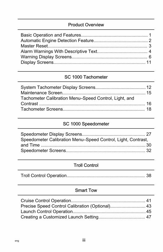
Basic Operation and FeaturesNOTE: Descriptive text alarm warning screens are displayed with2007 and newer engines.
46346
System Tachometer System Speedometer
Power up: Each gauge will power up when the ignition is turnedon. The gauges will stay on as long as the ignition is on.Lights: Adjusts the brightness and contrast of the gauge.Buttons: The "MODE/SELECT" button is used for selectinginformation screens. The "+" and "–" buttons are used for settingengine speed for troll control, and setting gauge calibrations.Troll control: Sets and controls the idle speed of the engine fortrolling without using the throttle.Engine Guardian System: Monitors the critical sensors on theengine for any early indication of problems. The system willrespond to a problem by reducing engine speed and alerting theoperator to a potentially damaging situation.Warning system: The system sounds the warning horn anddisplays the warning with descriptive text.IMPORTANT: Optional sensors such as depth, fuel, paddlewheel, and steering angle, should always be connected to thestarboard engine when using SmartCraft gauges version 4.0 orlater.
PRODUCT OVERVIEW
2 eng
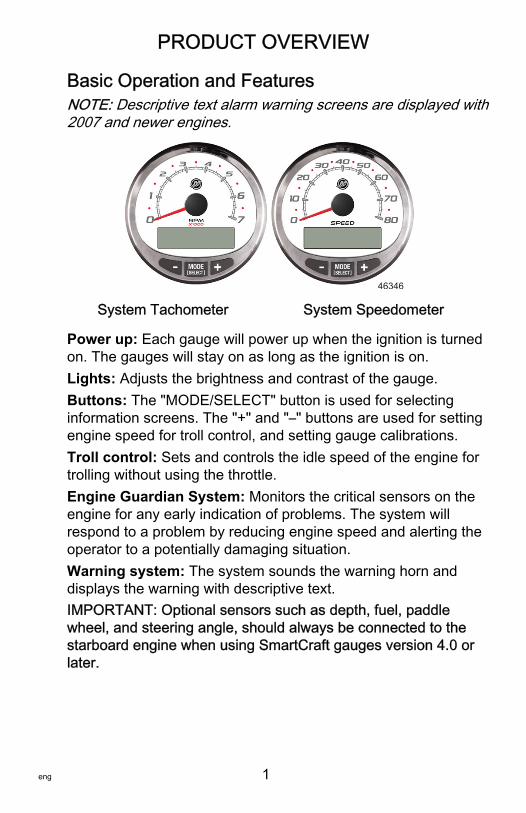
PRODUCTS WITH EMISSIONS CONTROLAfter the ignition is turned on, the tachometer will display thename of the gauge and the version of the software forapproximately two seconds. In the upper left‑hand corner of thedisplay, a small engine icon will also be visible. The icon is arepresentation the power package has emissions controlonboard diagnostics, also known as OBD. The icon will only beseen during the key up process unless a system fault isdetected. When a fault is detected, the OBD icon will bedisplayed in the upper left‑hand corner on all system screens.
a - OBD iconb - Software version
Automatic Engine Detection FeatureThe System Tachometer/Speedometer has an automatic enginedetection feature. This feature automatically detects whichengine type is used and configures the gauge to match thatengine type.The first power up of the gauge, or after a Master Reset, thegauge will display "AUTODETECT". Press the "MODE/SELECT"button to start the automatic engine detection feature and thegauge will determine the engine type. This will preset the datamonitoring screens to make the initial setup easier.
AUTODETECTENGINE SMARTSCREEN
PRESS MODE/SELECT TO START24298
If the gauge shows a warning of "NO STARBOARD ENGINE" or"MULTIPLE STARBOARD ENGINES", the engine location (portand starboard) must be selected by an authorized dealerequipped with the computer diagnostic system (CDS) tool.
MERCURY
13469S Cmart raft v X.X
a
b
PRODUCT OVERVIEW
eng 3
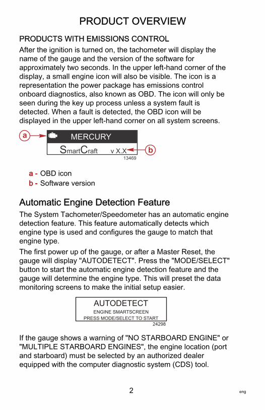
Master ResetReturns the gauge to the factory defaults through the MasterReset command.IMPORTANT: Performing a Master Reset will reset the unit tothe factory defaults, thus eliminating any installation andcalibrations performed during set up of product.Press the "‑" and "+" buttons simultaneously for approximately10 seconds (until the graphic bars collide) to restore the unit tofactory default settings. Press the "MODE/SELECT" button toconfirm.
22660
MASTERRESET
MASTERRESETERASE CALIBRATION !
PRESS MODE/SELECT TO CONFIRM
PRODUCT OVERVIEW
4 eng
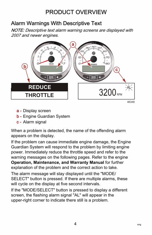
Alarm Warnings With Descriptive TextNOTE: Descriptive text alarm warning screens are displayed with2007 and newer engines.
a - Display screenb - Engine Guardian Systemc - Alarm signal
When a problem is detected, the name of the offending alarmappears on the display.If the problem can cause immediate engine damage, the EngineGuardian System will respond to the problem by limiting enginepower. Immediately reduce the throttle speed and refer to thewarning messages on the following pages. Refer to the engineOperation, Maintenance, and Warranty Manual for furtherexplanation of the problem and the correct action to take.The alarm message will stay displayed until the "MODE/SELECT" button is pressed. If there are multiple alarms, thesewill cycle on the display at five second intervals.If the "MODE/SELECT" button is pressed to display a differentscreen, the flashing alarm signal "AL" will appear in theupper‑right corner to indicate there still is a problem.
a
3200 RPM
AL
b c
REDUCETHROTTLE
46348
PRODUCT OVERVIEW
eng 5
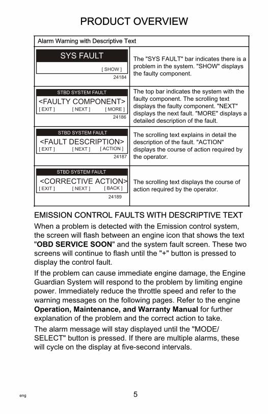
Alarm Warning with Descriptive Text
[ SHOW ]
SYS FAULT
24184
The "SYS FAULT" bar indicates there is aproblem in the system. "SHOW" displaysthe faulty component.
[ MORE ][ NEXT ][ EXIT ]
STBD SYSTEM FAULT
<FAULTY COMPONENT>
24186
STBD SYSTEM FAULT The top bar indicates the system with thefaulty component. The scrolling textdisplays the faulty component. "NEXT"displays the next fault. "MORE" displays adetailed description of the fault.
[ ACTION ][ NEXT ][ EXIT ]
STBD SYSTEM FAULT
<FAULT DESCRIPTION>
24187
The scrolling text explains in detail thedescription of the fault. "ACTION"displays the course of action required bythe operator.
[ BACK ][ NEXT ][ EXIT ]
STBD SYSTEM FAULT
<CORRECTIVE ACTION>
24189
The scrolling text displays the course ofaction required by the operator.
EMISSION CONTROL FAULTS WITH DESCRIPTIVE TEXTWhen a problem is detected with the Emission control system,the screen will flash between an engine icon that shows the text"OBD SERVICE SOON" and the system fault screen. These twoscreens will continue to flash until the "+" button is pressed todisplay the control fault.If the problem can cause immediate engine damage, the EngineGuardian System will respond to the problem by limiting enginepower. Immediately reduce the throttle speed and refer to thewarning messages on the following pages. Refer to the engineOperation, Maintenance, and Warranty Manual for furtherexplanation of the problem and the correct action to take.The alarm message will stay displayed until the "MODE/SELECT" button is pressed. If there are multiple alarms, thesewill cycle on the display at five‑second intervals.
PRODUCT OVERVIEW
6 eng
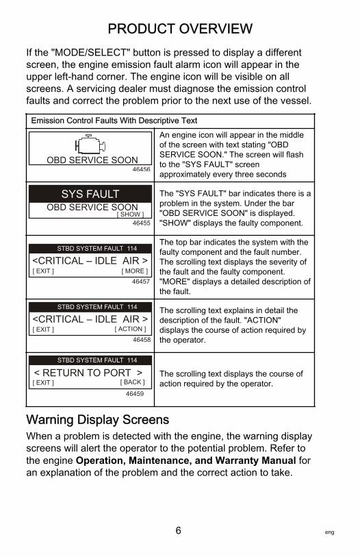
If the "MODE/SELECT" button is pressed to display a differentscreen, the engine emission fault alarm icon will appear in theupper left‑hand corner. The engine icon will be visible on allscreens. A servicing dealer must diagnose the emission controlfaults and correct the problem prior to the next use of the vessel.
Emission Control Faults With Descriptive Text
46456OBD SERVICE SOON
An engine icon will appear in the middleof the screen with text stating "OBDSERVICE SOON." The screen will flashto the "SYS FAULT" screenapproximately every three seconds
[ SHOW ]
SYS FAULT
46455
OBD SERVICE SOONThe "SYS FAULT" bar indicates there is aproblem in the system. Under the bar"OBD SERVICE SOON" is displayed."SHOW" displays the faulty component.
[ MORE ][ EXIT ]
STBD SYSTEM FAULT
<CRITICAL – IDLE AIR >
46457
STBD SYSTEM FAULT 114The top bar indicates the system with thefaulty component and the fault number.The scrolling text displays the severity ofthe fault and the faulty component."MORE" displays a detailed description ofthe fault.
[ ACTION ][ EXIT ]46458
STBD SYSTEM FAULT
<CRITICAL – IDLE AIR >STBD SYSTEM FAULT 114 The scrolling text explains in detail the
description of the fault. "ACTION"displays the course of action required bythe operator.
[ BACK ][ EXIT ]< RETURN TO PORT >
46459
STBD SYSTEM FAULTSTBD SYSTEM FAULT 114
The scrolling text displays the course ofaction required by the operator.
Warning Display ScreensWhen a problem is detected with the engine, the warning displayscreens will alert the operator to the potential problem. Refer tothe engine Operation, Maintenance, and Warranty Manual foran explanation of the problem and the correct action to take.
PRODUCT OVERVIEW
eng 7
PROBLEM TACHOMETER DISPLAY SPEEDOMETERDISPLAY
BATTERY ×
ENGINE DATA BUS ×
FAULT ‑ HORN ×
FAULT ‑ IGNITION ×
FAULT ‑ INJECTOR ×
FAULT ‑ OIL PUMP ×
FAULT ‑ SENSOR ×
FAULT ‑ WATER TEMP ×
LOW FUEL ×
LOW OIL ×
FAULT ‑ OIL TEMP ×
OIL PSI ×
OVERHEAT ×
OVERSPEED ×
FAULT ‑ OIL PRESSURE ×
RESERVE OIL ×
SYSTEM FAULT –OBD SERVICE SOON ×
WATER IN FUEL ×
FAULT ‑ MAP ×
FAULT ‑ MAT ×
FAULT ‑ TPS ×
PRODUCT OVERVIEW
8 eng
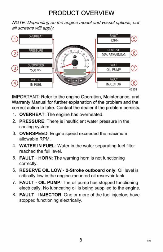
NOTE: Depending on the engine model and vessel options, notall screens will apply.
OVERHEAT
PRESSURE
OVERSPEED
WATER
FAULT
RESERVE
FAULT
FAULT
7500 RPM
IN FUEL
HORN
90% REMAINING
OIL PUMP
INJECTOR46351
1
2
3
4
5
6
7
8
IMPORTANT: Refer to the engine Operation, Maintenance, andWarranty Manual for further explanation of the problem and thecorrect action to take. Contact the dealer if the problem persists.1. OVERHEAT: The engine has overheated.2. PRESSURE: There is insufficient water pressure in the
cooling system.3. OVERSPEED: Engine speed exceeded the maximum
allowable RPM.4. WATER IN FUEL: Water in the water separating fuel filter
reached the full level.5. FAULT ‑ HORN: The warning horn is not functioning
correctly.6. RESERVE OIL LOW ‑ 2‑Stroke outboard only: Oil level is
critically low in the engine‑mounted oil reservoir tank.7. FAULT ‑ OIL PUMP: The oil pump has stopped functioning
electrically. No lubricating oil is being supplied to the engine.8. FAULT ‑ INJECTOR: One or more of the fuel injectors have
stopped functioning electrically.
PRODUCT OVERVIEW
eng 9
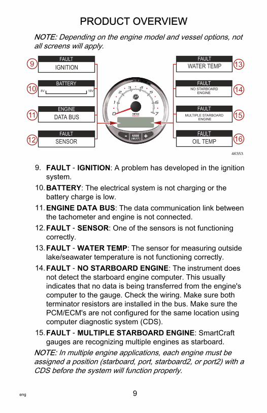
NOTE: Depending on the engine model and vessel options, notall screens will apply.
FAULT
BATTERY
FAULT
FAULT
FAULT
FAULT
FAULTSENSOR
WATER TEMP
OIL TEMP
46353
ENGINEDATA BUS
IGNITION
NO STARBOARD ENGINE
MULTIPLE STARBOARD ENGINE
8V 18V
9
10
11
12
13
14
15
16
9. FAULT ‑ IGNITION: A problem has developed in the ignitionsystem.
10.BATTERY: The electrical system is not charging or thebattery charge is low.
11.ENGINE DATA BUS: The data communication link betweenthe tachometer and engine is not connected.
12.FAULT ‑ SENSOR: One of the sensors is not functioningcorrectly.
13.FAULT ‑ WATER TEMP: The sensor for measuring outsidelake/seawater temperature is not functioning correctly.
14.FAULT ‑ NO STARBOARD ENGINE: The instrument doesnot detect the starboard engine computer. This usuallyindicates that no data is being transferred from the engine'scomputer to the gauge. Check the wiring. Make sure bothterminator resistors are installed in the bus. Make sure thePCM/ECM's are not configured for the same location usingcomputer diagnostic system (CDS).
15.FAULT ‑ MULTIPLE STARBOARD ENGINE: SmartCraftgauges are recognizing multiple engines as starboard.
NOTE: In multiple engine applications, each engine must beassigned a position (starboard, port, starboard2, or port2) with aCDS before the system will function properly.
PRODUCT OVERVIEW
10 eng
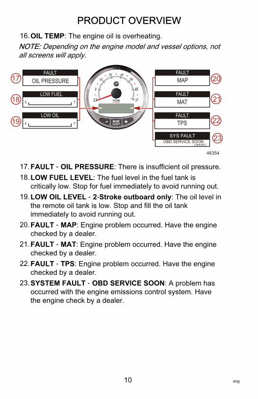
16.OIL TEMP: The engine oil is overheating.NOTE: Depending on the engine model and vessel options, notall screens will apply.
FAULT
LOW FUEL
LOW OIL
FAULT
FAULT
FAULT
MAP
MAT
TPS
OIL PRESSURE
E F
E F
46354
17
18
19
21
22
20
[ SHOW ]
SYS FAULTOBD SERVICE SOON 23
17.FAULT ‑ OIL PRESSURE: There is insufficient oil pressure.18.LOW FUEL LEVEL: The fuel level in the fuel tank is
critically low. Stop for fuel immediately to avoid running out.19.LOW OIL LEVEL ‑ 2‑Stroke outboard only: The oil level in
the remote oil tank is low. Stop and fill the oil tankimmediately to avoid running out.
20.FAULT ‑ MAP: Engine problem occurred. Have the enginechecked by a dealer.
21.FAULT ‑ MAT: Engine problem occurred. Have the enginechecked by a dealer.
22.FAULT ‑ TPS: Engine problem occurred. Have the enginechecked by a dealer.
23.SYSTEM FAULT ‑ OBD SERVICE SOON: A problem hasoccurred with the engine emissions control system. Havethe engine check by a dealer.
PRODUCT OVERVIEW
eng 11
Display ScreensTachometer Display Screen Speedometer Display Screen
Engine Break‑in (2‑Stroke outboardonly) Clock ‑ Air/Sea Temp
Engine Temperature Fuel Used
Oil Temperature Cog ‑ If there is a GPS input
Oil PSI Distance and Fuel to Waypoint
Trim and RPM Speed
Trim and Water Pressure Estimated Range
Water Pressure Instant and Average Fuel Economy
Battery Voltage and Engine Hours Trip Odometer
Fuel Flow and Fuel Used Fuel Tank Levels
Speed and Sea Temperature Oil Tank Levels
Battery Voltage Fresh Water Levels
% Fuel Remaining (Fuel Tank 1) Waste Water levels
Depth Steering Angle (MerCruiser only)
Trim Position Tabs
Fuel PSI Dual EngineRPM Trim and RPM Synchronizer
Maintenance
Quick Reference ScreenBattery, Temperature, PSI
SC 1000 TACHOMETER
12 eng
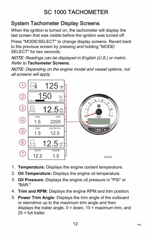
System Tachometer Display ScreensWhen the ignition is turned on, the tachometer will display thelast screen that was visible before the ignition was turned off.Press "MODE/SELECT" to change display screens. Revert backto the previous screen by pressing and holding "MODE/SELECT" for two seconds.NOTE: Readings can be displayed in English (U.S.) or metric.Refer to Tachometer Screens.NOTE: Depending on the engine model and vessel options, notall screens will apply.
F1251
2
3
4
5
6
7
OILPSI12.5
150HOT
FOIL
COLD
50349
TRIM WATER PSI
12.51.5
TRIM RPM
22051.5
12.5 H20PSI
VOLTS HOURS
12.2 1.5
1. Temperature: Displays the engine coolant temperature.2. Oil Temperature: Displays the engine oil temperature.3. Oil Pressure: Displays the engine oil pressure in "PSI" or
"BAR."4. Trim and RPM: Displays the engine RPM and trim position.5. Power Trim Angle: Displays the trim angle of the outboard
or sterndrive up to the maximum trim angle and thendisplays the trailer angle. 0 = down, 10 = maximum trim, and25 = full trailer.
SC 1000 TACHOMETER
eng 13
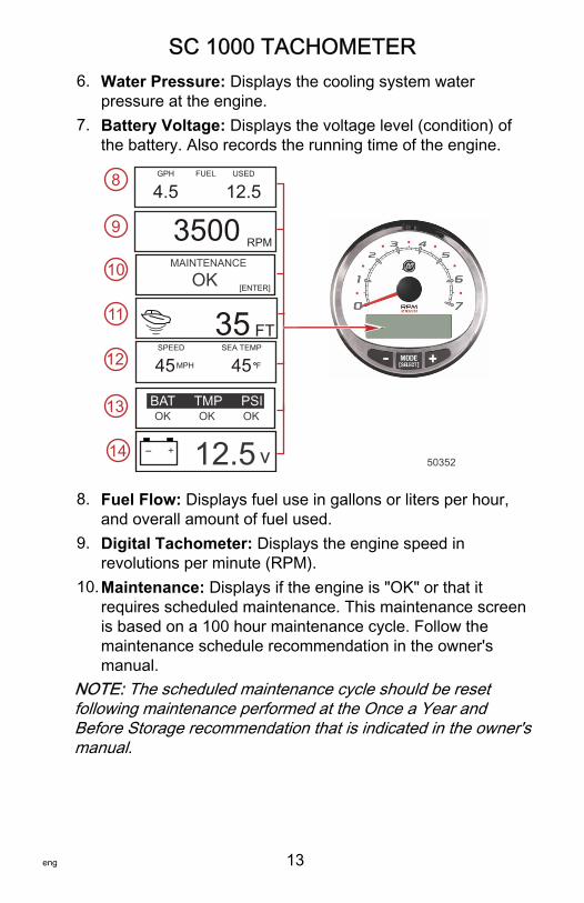
6. Water Pressure: Displays the cooling system waterpressure at the engine.
7. Battery Voltage: Displays the voltage level (condition) ofthe battery. Also records the running time of the engine.
RPM3500
GPH USED
12.54.5FUEL
SPEED SEA TEMP
MPH 45 45 F
35 FT
OK OK OKBAT TMP PSI
MAINTENANCE
OK [ENTER]
12.5- v 50352
8
9
10
11
12
13
14
8. Fuel Flow: Displays fuel use in gallons or liters per hour,and overall amount of fuel used.
9. Digital Tachometer: Displays the engine speed inrevolutions per minute (RPM).
10.Maintenance: Displays if the engine is "OK" or that itrequires scheduled maintenance. This maintenance screenis based on a 100 hour maintenance cycle. Follow themaintenance schedule recommendation in the owner'smanual.
NOTE: The scheduled maintenance cycle should be resetfollowing maintenance performed at the Once a Year andBefore Storage recommendation that is indicated in the owner'smanual.
SC 1000 TACHOMETER
14 eng
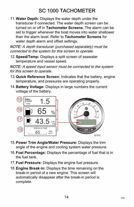
11.Water Depth: Displays the water depth under thetransducer if connected. The water depth screen can beturned on or off in Tachometer Screens. The alarm can beset to trigger whenever the boat moves into water shallowerthan the alarm level. Refer to Tachometer Screens forwater depth alarm and offset settings.
NOTE: A depth transducer (purchased separately) must beconnected to the system for this screen to operate.12.Speed/Temp: Displays a split screen of seawater
temperature and vessel speed.NOTE: A speed input sensor must be connected to the systemfor this screen to operate.13.Quick Reference Screen: Indicates that the battery, engine
temperature, and pressures are operating properly.14.Battery Voltage: Displays in large numbers the current
voltage of the battery.
BREAK-IN TIME
MINLEFT65
FUEL PSI43.5
TRIM 1.565 %
50353
15
16
17
18
15.Power Trim Angle/Water Pressure: Displays the trimangle of the engine and cooling system water pressure.
16.Fuel Percentage: Displays the percentage of fuel that is inthe fuel tank.
17.Fuel Pressure: Displays the engine fuel pressure.18.Engine Break‑in: Displays the time remaining on the
break‑in period of a new engine. This screen willautomatically disappear after the break‑in period iscomplete.
SC 1000 TACHOMETER
eng 15
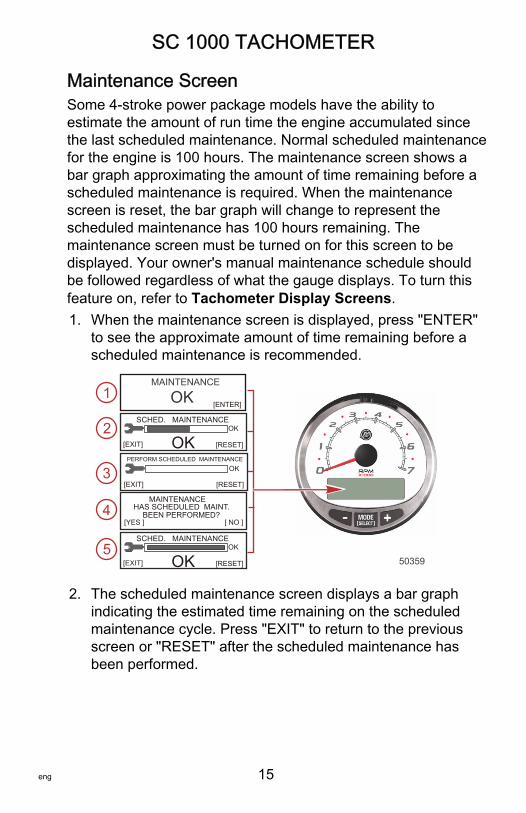
Maintenance ScreenSome 4‑stroke power package models have the ability toestimate the amount of run time the engine accumulated sincethe last scheduled maintenance. Normal scheduled maintenancefor the engine is 100 hours. The maintenance screen shows abar graph approximating the amount of time remaining before ascheduled maintenance is required. When the maintenancescreen is reset, the bar graph will change to represent thescheduled maintenance has 100 hours remaining. Themaintenance screen must be turned on for this screen to bedisplayed. Your owner's manual maintenance schedule shouldbe followed regardless of what the gauge displays. To turn thisfeature on, refer to Tachometer Display Screens.1. When the maintenance screen is displayed, press "ENTER"
to see the approximate amount of time remaining before ascheduled maintenance is recommended.
MAINTENANCE
OK [ENTER]
SCHED. MAINTENANCEOK
OK[EXIT] [RESET]
PERFORM SCHEDULED MAINTENANCEOK
[EXIT] [RESET]
MAINTENANCE
[ NO ][YES ]
HAS SCHEDULED MAINT.BEEN PERFORMED?
SCHED. MAINTENANCEOK
OK[EXIT] [RESET] 50359
1
2
3
4
5
2. The scheduled maintenance screen displays a bar graphindicating the estimated time remaining on the scheduledmaintenance cycle. Press "EXIT" to return to the previousscreen or "RESET" after the scheduled maintenance hasbeen performed.
SC 1000 TACHOMETER
16 eng
3. If the amount of time since the last scheduled maintenancehas passed 100 hours, the screen will show "PERFORMSCHEDULED MAINTENANCE" and the bar graph will notbe visible. Press "EXIT" to return to the previous screen or"RESET."
4. After pressing "RESET" the screen goes to the"MAINTENANCE" screen. The "MAINTENANCE" screen willdisplay "HAS SCHEDULED MAINT. BEEN PERFORMED?"Press "YES" to reset the maintenance schedule, or press"NO" to return to the previous screen.
5. After pressing "YES" the screen will show the bar graph hasbeen reset to represent 100 hours of operation before thenext scheduled maintenance. Press "EXIT" to return the"MAINTENANCE OK" screen.
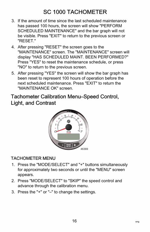
Tachometer Calibration Menu–Speed Control,Light, and Contrast
46369
TACHOMETER MENU1. Press the "MODE/SELECT" and "+" buttons simultaneously
for approximately two seconds or until the "MENU" screenappears.
2. Press "MODE/SELECT" to "SKIP" the speed control andadvance through the calibration menu.
3. Press the "+" or "–" to change the settings.
SC 1000 TACHOMETER
eng 17
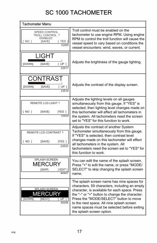
Tachometer Menu
[SAVE] [ YES ]
SPEED CONTROLTROLL CONTROL ?
[ NO ]ENABLED
52680
Troll control must be enabled on thetachometer to use engine RPM. Using engineRPM to control the troll function will cause thevessel speed to vary based on conditions thevessel encounters: wind, waves, or current.
LIGHT[DOWN] [SAVE] [ UP ]
23517
Adjusts the brightness of the gauge lighting.
CONTRAST[DOWN] [SAVE] [ UP ]
23519
Adjusts the contrast of the display screen.
[ NO ] [SAVE] [YES ]23532
REMOTE LCD LIGHT ?Adjusts the lighting levels on all gaugessimultaneously from this gauge. If "YES" isselected, then lighting level changes made onthis tachometer will effect all tachometers inthe system. All tachometers need the screenset to "YES" for this function to work.
[ NO ] [SAVE] [YES ]
23533
REMOTE LCD CONTRAST ?
Adjusts the contrast of another SystemTachometer simultaneously from this gauge.If "YES" is selected, then contrast levelchanges made on this tachometer will effectall tachometers in the system. Alltachometers need the screen set to "YES" forthis function to work.
SPLASH SCREEN
[SKIP] [ EDIT ]46447
MERCURYYou can edit the name of the splash screen.Press "+" to edit the name, or press "MODE/SELECT" to skip changing the splash screenname.
SPLASH SCREEN
[DOWN] [ UP ]30246
_MERCURY[NEXT]
The splash screen name has nine spaces forcharacters. 59 characters, including an emptycharacter, is available for each space. Pressthe "–" or "+" button to change the character.Press the "MODE/SELECT" button to moveto the next space. All nine splash screenname spaces must be selected before exitingthe splash screen option.
SC 1000 TACHOMETER
18 eng
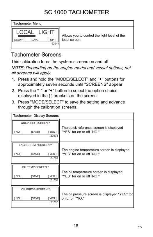
Tachometer Menu
[DOWN] [ UP ]
LOCAL LIGHT[SAVE]
52644
Allows you to control the light level of thelocal screen.
Tachometer ScreensThis calibration turns the system screens on and off.NOTE: Depending on the engine model and vessel options, notall screens will apply.1. Press and hold the "MODE/SELECT" and "+" buttons for
approximately seven seconds until "SCREENS" appear.2. Press the "–" or "+" button to select the option choice
displayed in the [ ] brackets on the screen.3. Press "MODE/SELECT" to save the setting and advance
through the calibration screens.
Tachometer–Display Screens
QUICK REF SCREEN ?
[ NO ] [SAVE] [ YES ]23978
The quick reference screen is displayed"YES" for on or off "NO."
ENGINE TEMP SCREEN ?
[ NO ] [SAVE] [ YES ]23783
The engine temperature screen is displayed"YES" for on or off "NO."
OIL TEMP SCREEN ?
[ NO ] [SAVE] [ YES ]23786
The oil temperature screen is displayed"YES" for on or off "NO."
OIL PRESS SCREEN ?
[ NO ] [SAVE] [ YES ]23787
The oil pressure screen is displayed "YES" foron or off "NO."
SC 1000 TACHOMETER
eng 19
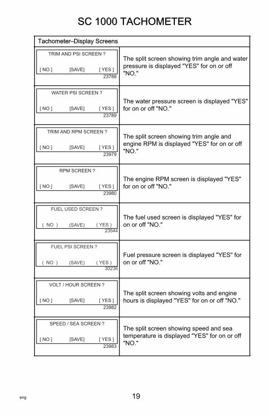
Tachometer–Display Screens
TRIM AND PSI SCREEN ?
[ NO ] [SAVE] [ YES ]23788
The split screen showing trim angle and waterpressure is displayed "YES" for on or off"NO."
WATER PSI SCREEN ?
[ NO ] [SAVE] [ YES ]23789
The water pressure screen is displayed "YES"for on or off "NO."
TRIM AND RPM SCREEN ?
[ NO ] [SAVE] [ YES ]23979
The split screen showing trim angle andengine RPM is displayed "YES" for on or off"NO."
RPM SCREEN ?
[ NO ] [SAVE] [ YES ]23980
The engine RPM screen is displayed "YES"for on or off "NO."
( NO ) (SAVE) ( YES )23544
FUEL USED SCREEN ?
The fuel used screen is displayed "YES" foron or off "NO."
( NO ) (SAVE) ( YES )30236
FUEL PSI SCREEN ?
Fuel pressure screen is displayed "YES" foron or off "NO."
VOLT / HOUR SCREEN ?
[ NO ] [SAVE] [ YES ]23982
The split screen showing volts and enginehours is displayed "YES" for on or off "NO."
SPEED / SEA SCREEN ?
[ NO ] [SAVE] [ YES ]23983
The split screen showing speed and seatemperature is displayed "YES" for on or off"NO."
SC 1000 TACHOMETER
20 eng
Tachometer–Display Screens
(DOWN ) (SAVE) ( UP )30242
OFFSET = F
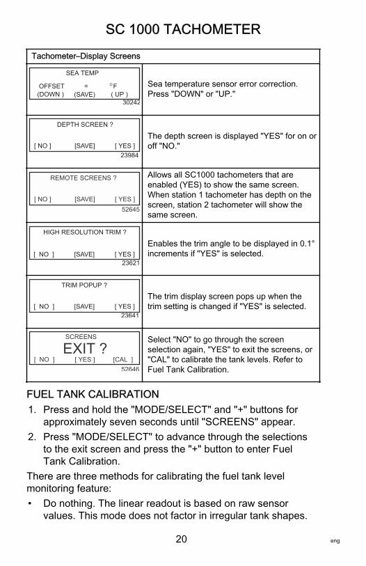
SEA TEMPO Sea temperature sensor error correction.
Press "DOWN" or "UP."
DEPTH SCREEN ?
[ NO ] [SAVE] [ YES ]23984
The depth screen is displayed "YES" for on oroff "NO."
REMOTE SCREENS ?
[ NO ] [SAVE] [ YES ]52645
Allows all SC1000 tachometers that areenabled (YES) to show the same screen.When station 1 tachometer has depth on thescreen, station 2 tachometer will show thesame screen.
[SAVE] [ YES ]23621
HIGH RESOLUTION TRIM ?
[ NO ]Enables the trim angle to be displayed in 0.1°increments if "YES" is selected.
[SAVE] [ YES ]23641
TRIM POPUP ?
[ NO ]The trim display screen pops up when thetrim setting is changed if "YES" is selected.
[ NO ] [ YES ] [CAL ]
SCREENS
EXIT ?52646
Select "NO" to go through the screenselection again, "YES" to exit the screens, or"CAL" to calibrate the tank levels. Refer toFuel Tank Calibration.
FUEL TANK CALIBRATION1. Press and hold the "MODE/SELECT" and "+" buttons for
approximately seven seconds until "SCREENS" appear.2. Press "MODE/SELECT" to advance through the selections
to the exit screen and press the "+" button to enter FuelTank Calibration.
There are three methods for calibrating the fuel tank levelmonitoring feature:• Do nothing. The linear readout is based on raw sensor
values. This mode does not factor in irregular tank shapes.
SC 1000 TACHOMETER
eng 21
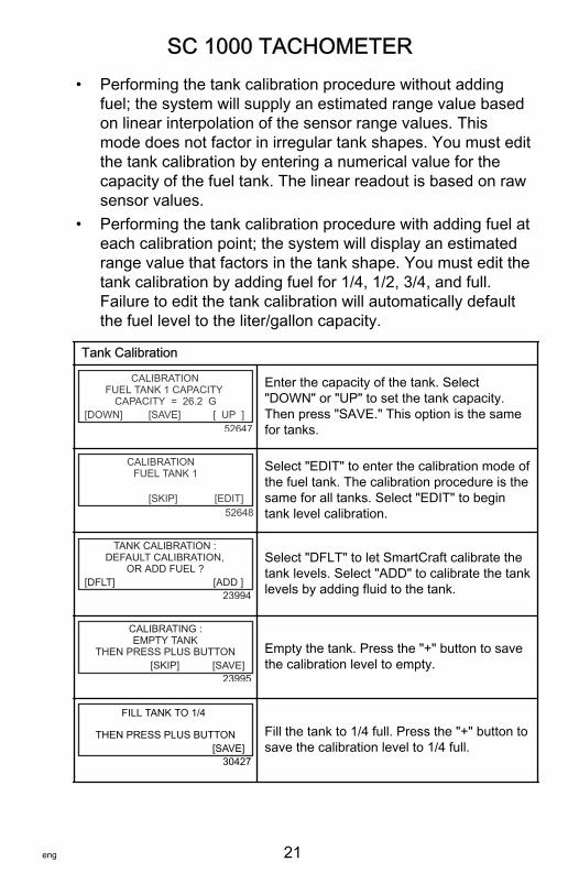
• Performing the tank calibration procedure without addingfuel; the system will supply an estimated range value basedon linear interpolation of the sensor range values. Thismode does not factor in irregular tank shapes. You must editthe tank calibration by entering a numerical value for thecapacity of the fuel tank. The linear readout is based on rawsensor values.
• Performing the tank calibration procedure with adding fuel ateach calibration point; the system will display an estimatedrange value that factors in the tank shape. You must edit thetank calibration by adding fuel for 1/4, 1/2, 3/4, and full.Failure to edit the tank calibration will automatically defaultthe fuel level to the liter/gallon capacity.
Tank Calibration
FUEL TANK 1 CAPACITYCALIBRATION
CAPACITY = 26.2 G[DOWN] [SAVE] [ UP ]
52647
Enter the capacity of the tank. Select"DOWN" or "UP" to set the tank capacity.Then press "SAVE." This option is the samefor tanks.
FUEL TANK 1CALIBRATION
[SKIP] [EDIT]52648
Select "EDIT" to enter the calibration mode ofthe fuel tank. The calibration procedure is thesame for all tanks. Select "EDIT" to begintank level calibration.
DEFAULT CALIBRATION,TANK CALIBRATION :
OR ADD FUEL ?[DFLT] [ADD ]
23994
Select "DFLT" to let SmartCraft calibrate thetank levels. Select "ADD" to calibrate the tanklevels by adding fluid to the tank.
EMPTY TANKCALIBRATING :
THEN PRESS PLUS BUTTON[SKIP] [SAVE]
23995
Empty the tank. Press the "+" button to savethe calibration level to empty.
FILL TANK TO 1/4
THEN PRESS PLUS BUTTON[SAVE]
30427
Fill the tank to 1/4 full. Press the "+" button tosave the calibration level to 1/4 full.
SC 1000 TACHOMETER
22 eng
Tank Calibration
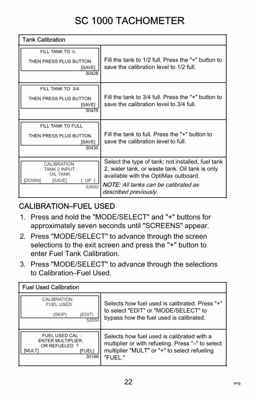
FILL TANK TO ½
THEN PRESS PLUS BUTTON[SAVE]
30428
Fill the tank to 1/2 full. Press the "+" button tosave the calibration level to 1/2 full.
FILL TANK TO 3/4
THEN PRESS PLUS BUTTON[SAVE]
30429
Fill the tank to 3/4 full. Press the "+" button tosave the calibration level to 3/4 full.
FILL TANK TO FULL
THEN PRESS PLUS BUTTON[SAVE]
30430
Fill the tank to full. Press the "+" button tosave the calibration level to full.
TANK 2 INPUTOIL TANK
CALIBRATION
[SAVE][DOWN] [ UP ]52652
Select the type of tank; not installed, fuel tank2, water tank, or waste tank. Oil tank is onlyavailable with the OptiMax outboard.
NOTE: All tanks can be calibrated asdescribed previously.
CALIBRATION–FUEL USED1. Press and hold the "MODE/SELECT" and "+" buttons for
approximately seven seconds until "SCREENS" appear.2. Press "MODE/SELECT" to advance through the screen
selections to the exit screen and press the "+" button toenter Fuel Tank Calibration.
3. Press "MODE/SELECT" to advance through the selectionsto Calibration–Fuel Used.
Fuel Used Calibration
(SKIP) (EDIT)
CALIBRATION FUEL USED
52650
Selects how fuel used is calibrated. Press "+"to select "EDIT" or "MODE/SELECT" tobypass how the fuel used is calibrated.
[FUEL]
FUEL USED CAL : ENTER MULTIPLIER, OR REFUELED ?
[MULT]30166
Selects how fuel used is calibrated with amultiplier or with refueling. Press "–" to selectmultiplier "MULT" or "+" to select refueling"FUEL."
SC 1000 TACHOMETER
eng 23
Fuel Used Calibration
[DOWN] [SAVE] [ UP ]
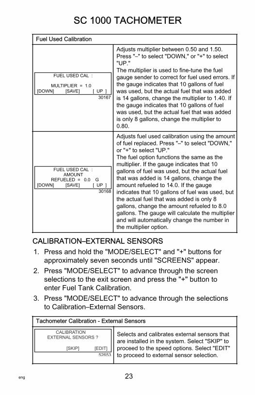
FUEL USED CAL : MULTIPLIER = 1.0
30167
Adjusts multiplier between 0.50 and 1.50.Press "–" to select "DOWN," or "+" to select"UP."The multiplier is used to fine‑tune the fuelgauge sender to correct for fuel used errors. Ifthe gauge indicates that 10 gallons of fuelwas used, but the actual fuel that was addedis 14 gallons, change the multiplier to 1.40. Ifthe gauge indicates that 10 gallons of fuelwas used, but the actual fuel that was addedis only 8 gallons, change the multiplier to0.80.
[DOWN] [SAVE] [ UP ]
FUEL USED CAL : AMOUNT REFUELED = 0.0 G
30168
Adjusts fuel used calibration using the amountof fuel replaced. Press "–" to select "DOWN,"or "+" to select "UP."The fuel option functions the same as themultiplier. If the gauge indicates that 10gallons of fuel was used, but the actual fuelthat was added is 14 gallons, change theamount refueled to 14.0. If the gaugeindicates that 10 gallons of fuel was used, butthe actual fuel that was added is only 8gallons, change the amount refueled to 8.0gallons. The gauge will calculate the multiplierand will automatically change the number inthe multiplier option.
CALIBRATION–EXTERNAL SENSORS1. Press and hold the "MODE/SELECT" and "+" buttons for
approximately seven seconds until "SCREENS" appear.2. Press "MODE/SELECT" to advance through the screen
selections to the exit screen and press the "+" button toenter Fuel Tank Calibration.
3. Press "MODE/SELECT" to advance through the selectionsto Calibration–External Sensors.
Tachometer Calibration ‑ External Sensors
EXTERNAL SENSORS ?CALIBRATION
[SKIP] [EDIT]52653
Selects and calibrates external sensors thatare installed in the system. Select "SKIP" toproceed to the speed options. Select "EDIT"to proceed to external sensor selection.
SC 1000 TACHOMETER
24 eng
Tachometer Calibration ‑ External Sensors
EXTERNAL SENSORSCALIBRATION
PITOT SENSOR ? YES[ NO ] [SAVE] [YES ]
52654
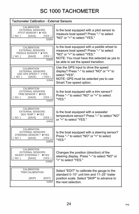
Is the boat equipped with a pitot sensor tomeasure boat speed? Press "–" to select"NO" or "+" to select "YES."
EXTERNAL SENSORSCALIBRATION
PADDLE SENSOR ? YES[ NO ] [SAVE] [YES ]
52655
Is the boat equipped with a paddle wheel tomeasure boat speed? Press "–" to select"NO" or "+" to select "YES."NOTE: You must have this selected as yes tobe able to set the speed transition.
(SAVE) ( YES )
CALIBRATION EXTERNAL SENSORS
( NO ) USE GPS SPEED ? YES
52656
Use the GPS input to drive the speeddisplay? Press "–" to select "NO" or "+" toselect "YES".NOTE: GPS must be selected yes to useSmart Tow speed option.
EXTERNAL SENSORSCALIBRATION
TRIM SENSOR ? YES[ NO ] [SAVE] [YES ]
52657
Is the boat equipped with a trim sensor?Press "–" to select "NO" or "+" to select"YES."
EXTERNAL SENSORSCALIBRATION
SEA TEMP ?[ NO ] [SAVE] [YES ]
YES
52658
Is the boat equipped with a seawatertemperature sensor? Press "–" to select "NO"or "+" to select "YES."
EXTERNAL SENSORSCALIBRATION
STEERING SENSOR ?[ NO ] [SAVE] [YES ]
YES
52659
Is the boat equipped with a steering sensor?Press "–" to select "NO" or "+" to select"YES."
EXTERNAL SENSORSCALIBRATION
INVERT STEERING ?[ NO ] [SAVE] [YES ]
YES
52660
Changes the position (direction) of thesteering display. Press "–" to select "NO" or"+" to select "YES."
TRIM CALIBRATIONCALIBRATION
[SKIP] [EDIT]52661
Select "EDIT" to calibrate the gauge to thestandard 0–10° unit trim and 11–25° trailerposition scale. Select "SKIP" to advance tothe next selection.
SC 1000 TACHOMETER
eng 25
Tachometer Calibration ‑ External Sensors
TRIM FULL DOWNCALIBRATION
THEN PRESS PLUS BUTTON[DFLT] [SKIP] [SAVE]
52662
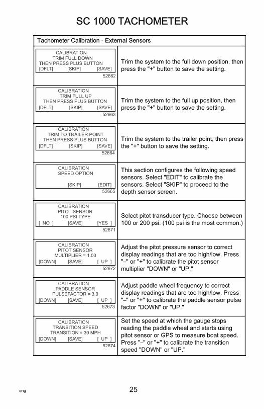
Trim the system to the full down position, thenpress the "+" button to save the setting.
TRIM FULL UPCALIBRATION
THEN PRESS PLUS BUTTON[DFLT] [SKIP] [SAVE]
52663
Trim the system to the full up position, thenpress the "+" button to save the setting.
TRIM TO TRAILER POINTCALIBRATION
THEN PRESS PLUS BUTTON[DFLT] [SKIP] [SAVE]
52664
Trim the system to the trailer point, then pressthe "+" button to save the setting.
SPEED OPTIONCALIBRATION
[SKIP] [EDIT]52665
This section configures the following speedsensors. Select "EDIT" to calibrate thesensors. Select "SKIP" to proceed to thedepth sensor screen.
PITOT SENSOR100 PSI TYPE
CALIBRATION
[ NO ] [SAVE] [YES ]52671
Select pitot transducer type. Choose between100 or 200 psi. (100 psi is the most common.)
PITOT SENSORCALIBRATION
[DOWN] [SAVE] [ UP ]MULTIPLIER = 1.00
52672
Adjust the pitot pressure sensor to correctdisplay readings that are too high/low. Press"–" or "+" to calibrate the pitot sensormultiplier "DOWN" or "UP."
PADDLE SENSORCALIBRATION
[DOWN] [SAVE] [ UP ]PULSEFACTOR = 3.0
52673
Adjust paddle wheel frequency to correctdisplay readings that are too high/low. Press"–" or "+" to calibrate the paddle sensor pulsefactor "DOWN" or "UP."
TRANSITION SPEEDCALIBRATION
[DOWN] [SAVE] [ UP ]TRANSITION = 30 MPH
52674
Set the speed at which the gauge stopsreading the paddle wheel and starts usingpitot sensor or GPS to measure boat speed.Press "–" or "+" to calibrate the transitionspeed "DOWN" or "UP."
SC 1000 TACHOMETER
26 eng
Tachometer Calibration ‑ External Sensors
DEPTH SENSORCALIBRATION
[DOWN] [SAVE] [ UP ]OFFSET = 3 FEET
52676
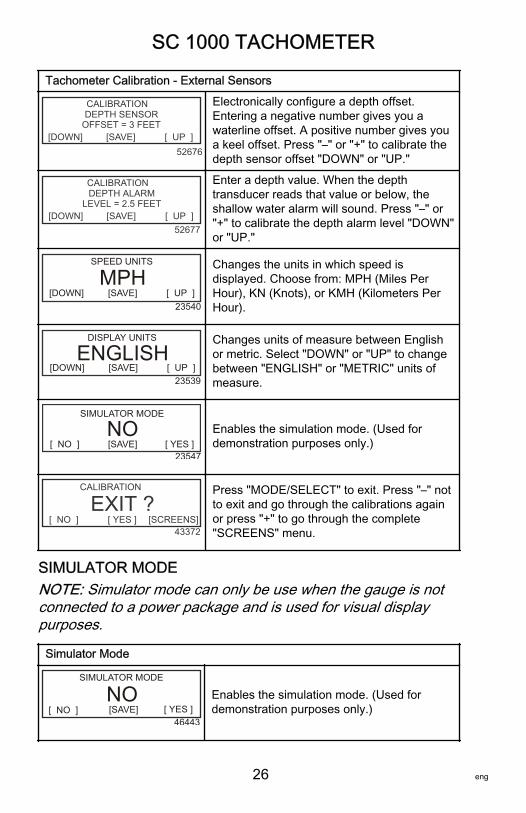
Electronically configure a depth offset.Entering a negative number gives you awaterline offset. A positive number gives youa keel offset. Press "–" or "+" to calibrate thedepth sensor offset "DOWN" or "UP."
DEPTH ALARMCALIBRATION
[DOWN] [SAVE] [ UP ]LEVEL = 2.5 FEET
52677
Enter a depth value. When the depthtransducer reads that value or below, theshallow water alarm will sound. Press "–" or"+" to calibrate the depth alarm level "DOWN"or "UP."
23540
SPEED UNITS
MPH[DOWN] [SAVE] [ UP ]
Changes the units in which speed isdisplayed. Choose from: MPH (Miles PerHour), KN (Knots), or KMH (Kilometers PerHour).
[DOWN] [SAVE] [ UP ]23539
DISPLAY UNITS
ENGLISHChanges units of measure between Englishor metric. Select "DOWN" or "UP" to changebetween "ENGLISH" or "METRIC" units ofmeasure.
[ NO ] [SAVE] [ YES ]23547
SIMULATOR MODE
NO Enables the simulation mode. (Used fordemonstration purposes only.)
[ NO ] [ YES ] [SCREENS]43372
CALIBRATION
EXIT ?Press "MODE/SELECT" to exit. Press "–" notto exit and go through the calibrations againor press "+" to go through the complete"SCREENS" menu.
SIMULATOR MODENOTE: Simulator mode can only be use when the gauge is notconnected to a power package and is used for visual displaypurposes.
Simulator Mode
[ NO ] [ YES ][SAVE]46443
SIMULATOR MODE
NO Enables the simulation mode. (Used fordemonstration purposes only.)
SC 1000 SPEEDOMETER
eng 27
Speedometer Display ScreensNOTE: Depending on the engine model and vessel options, notall screens will apply.
0 SPEED
10
2030 40 50
60
70
80
5:30 PM
70 60 FAIR
FSEA
FUEL 1E F
GAL90
E F
TABS
STBDPORT
1
2
3
4
5
FUEL 2 GAL110
0% 0%
INST M/G AVG
1.5 3.2RESET 46451
When the ignition is turned on, the speedometer will show thelast screen that was displayed before the ignition was turned off.Press "MODE/SELECT" to change display screens. Revert backto the previous screen by pressing and holding "MODE/SELECT" for two seconds.NOTE: Readings can be displayed in English (U.S.) or metric.Refer to Speedometer Screens.NOTE: The descriptions may not be in order on the gauge. Theorder may change depending on engine type.1. Clock ‑ Temp: Clock, air temperature, and water
temperature. The air and water temperature sensors mustbe connected to obtain display readings.
2. Fuel 1: Displays the amount of fuel remaining in fuel tank 1.3. Fuel 2: Displays the amount of fuel remaining in fuel tank 2,
water/waste tank level (if applicable.) This screen willautomatically display engine oil tank for an OptiMaxoutboard.
SC 1000 SPEEDOMETER
28 eng
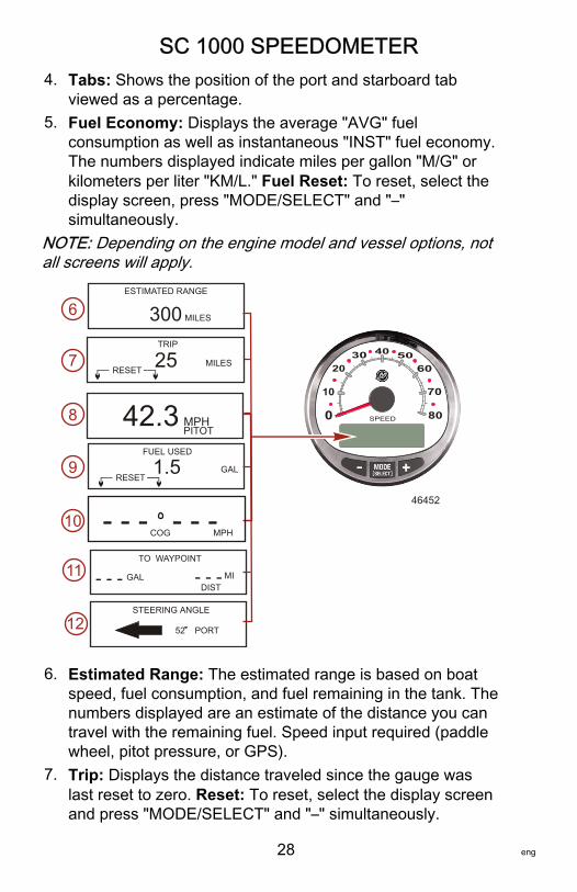
4. Tabs: Shows the position of the port and starboard tabviewed as a percentage.
5. Fuel Economy: Displays the average "AVG" fuelconsumption as well as instantaneous "INST" fuel economy.The numbers displayed indicate miles per gallon "M/G" orkilometers per liter "KM/L." Fuel Reset: To reset, select thedisplay screen, press "MODE/SELECT" and "–"simultaneously.
NOTE: Depending on the engine model and vessel options, notall screens will apply.
0 SPEED
10
2030 40 50
60
70
80
300
FUEL USED
1.5
ESTIMATED RANGE
MILES
TRIP
25 MILES
42.3 MPH
STEERING ANGLE
52 PORT
6
7
8
9
10
RESET
PITOT
RESETGAL
46452
COG MPH- - - - - - TO WAYPOINT
- - - - - - GAL MIDIST
11
12
6. Estimated Range: The estimated range is based on boatspeed, fuel consumption, and fuel remaining in the tank. Thenumbers displayed are an estimate of the distance you cantravel with the remaining fuel. Speed input required (paddlewheel, pitot pressure, or GPS).
7. Trip: Displays the distance traveled since the gauge waslast reset to zero. Reset: To reset, select the display screenand press "MODE/SELECT" and "–" simultaneously.
SC 1000 SPEEDOMETER
eng 29
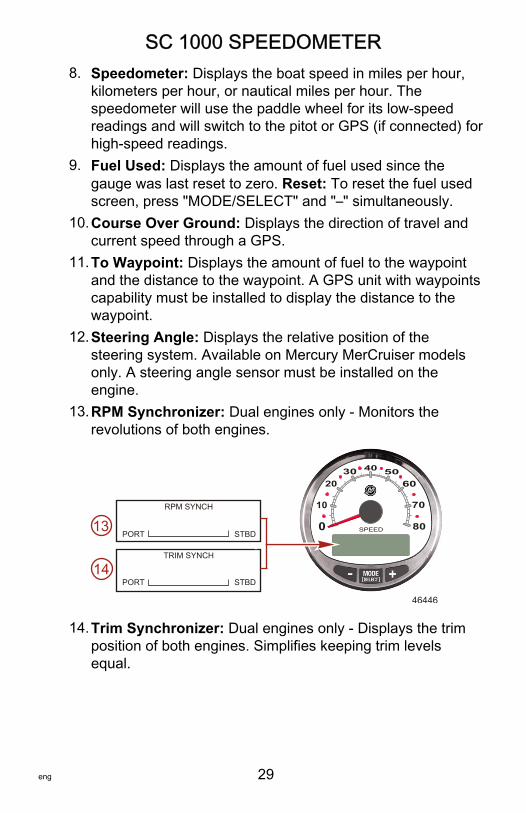
8. Speedometer: Displays the boat speed in miles per hour,kilometers per hour, or nautical miles per hour. Thespeedometer will use the paddle wheel for its low‑speedreadings and will switch to the pitot or GPS (if connected) forhigh‑speed readings.
9. Fuel Used: Displays the amount of fuel used since thegauge was last reset to zero. Reset: To reset the fuel usedscreen, press "MODE/SELECT" and "–" simultaneously.
10.Course Over Ground: Displays the direction of travel andcurrent speed through a GPS.
11.To Waypoint: Displays the amount of fuel to the waypointand the distance to the waypoint. A GPS unit with waypointscapability must be installed to display the distance to thewaypoint.
12.Steering Angle: Displays the relative position of thesteering system. Available on Mercury MerCruiser modelsonly. A steering angle sensor must be installed on theengine.
13.RPM Synchronizer: Dual engines only ‑ Monitors therevolutions of both engines.
0 SPEED
10
2030 40 50
60
70
80
46446
RPM SYNCH
STBDPORT
TRIM SYNCH
STBDPORT
13
14
14.Trim Synchronizer: Dual engines only ‑ Displays the trimposition of both engines. Simplifies keeping trim levelsequal.
SC 1000 SPEEDOMETER
30 eng
Speedometer Calibration Menu–Speed Control,Light, Contrast, and Time
46359
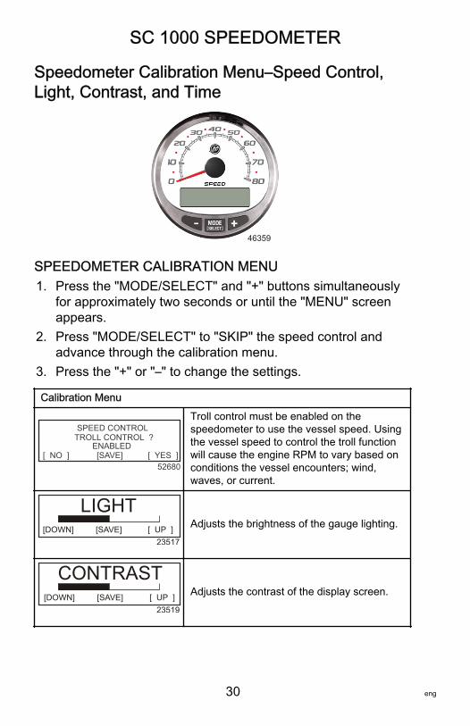
SPEEDOMETER CALIBRATION MENU1. Press the "MODE/SELECT" and "+" buttons simultaneously
for approximately two seconds or until the "MENU" screenappears.
2. Press "MODE/SELECT" to "SKIP" the speed control andadvance through the calibration menu.
3. Press the "+" or "–" to change the settings.
Calibration Menu
[SAVE] [ YES ]
SPEED CONTROLTROLL CONTROL ?
[ NO ]ENABLED
52680
Troll control must be enabled on thespeedometer to use the vessel speed. Usingthe vessel speed to control the troll functionwill cause the engine RPM to vary based onconditions the vessel encounters; wind,waves, or current.
LIGHT[DOWN] [SAVE] [ UP ]
23517
Adjusts the brightness of the gauge lighting.
CONTRAST[DOWN] [SAVE] [ UP ]
23519
Adjusts the contrast of the display screen.
SC 1000 SPEEDOMETER
eng 31
Calibration Menu
[ NO ] [SAVE] [YES ]23532
REMOTE LCD LIGHT ?Adjusts the lighting levels on all gaugessimultaneously from this gauge. If "YES" isselected, then lighting level changes made onthis tachometer will effect all tachometers inthe system. All tachometers need the screenset to "YES" for this function to work.
[ NO ] [SAVE] [YES ]
23533
REMOTE LCD CONTRAST ?
Adjusts the contrast of another SystemTachometer simultaneously from this gauge.If "YES" is selected, then contrast levelchanges made on this tachometer will effectall tachometers in the system. Alltachometers need the screen set to "YES" forthis function to work.
SPLASH SCREEN
[SKIP] [ EDIT ]46447
MERCURYYou can edit the name of the splash screen.Press "+" to edit the name, or press "MODE/SELECT" to skip changing the splash screenname.
SPLASH SCREEN
[DOWN] [ UP ]30246
_MERCURY[NEXT]
The splash screen name has nine spaces forcharacters. 59 characters, including an emptycharacter, is available for each space. Pressthe "–" or "+" button to change the character.Press the "MODE/SELECT" button to moveto the next space. All nine splash screenname spaces must be selected before exitingthe splash screen option.
[DOWN] [ UP ]
LOCAL LIGHT[SAVE]
52644
Allows you to control the light level of thelocal screen.
[ SKIP ] [EDIT ]
MENU
TIME52693
Sets the time. Select "EDIT" to format thetime or "SKIP" to advance to the next screen.
(DOWN) (SAVE) ( UP )23535
CALIBRATION TIME FORMAT 12H - M, D, Y
Formats the time as either 12 hourmonth‑day‑year or as 24 hourday‑month‑year. Select "DOWN" or "UP" tochange the format.
SC 1000 SPEEDOMETER
32 eng
Calibration Menu
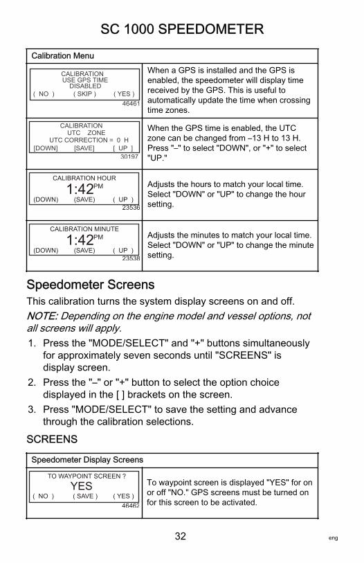
( NO ) ( SKIP ) ( YES )46461
CALIBRATION USE GPS TIME
DISABLED
When a GPS is installed and the GPS isenabled, the speedometer will display timereceived by the GPS. This is useful toautomatically update the time when crossingtime zones.
[DOWN] [SAVE] [ UP ]
CALIBRATION UTC ZONEUTC CORRECTION = 0 H
30197
When the GPS time is enabled, the UTCzone can be changed from –13 H to 13 H.Press "–" to select "DOWN", or "+" to select"UP."
(DOWN) (SAVE) ( UP )23536
CALIBRATION HOUR
1:42PM Adjusts the hours to match your local time.Select "DOWN" or "UP" to change the hoursetting.
(DOWN) (SAVE) ( UP )23538
CALIBRATION MINUTE
1:42PM Adjusts the minutes to match your local time.Select "DOWN" or "UP" to change the minutesetting.
Speedometer ScreensThis calibration turns the system display screens on and off.NOTE: Depending on the engine model and vessel options, notall screens will apply.1. Press the "MODE/SELECT" and "+" buttons simultaneously
for approximately seven seconds until "SCREENS" isdisplay screen.
2. Press the "–" or "+" button to select the option choicedisplayed in the [ ] brackets on the screen.
3. Press "MODE/SELECT" to save the setting and advancethrough the calibration selections.
SCREENS
Speedometer Display Screens
( NO ) ( SAVE ) ( YES )46462
TO WAYPOINT SCREEN ?
YES To waypoint screen is displayed "YES" for onor off "NO." GPS screens must be turned onfor this screen to be activated.
SC 1000 SPEEDOMETER
eng 33
Speedometer Display Screens
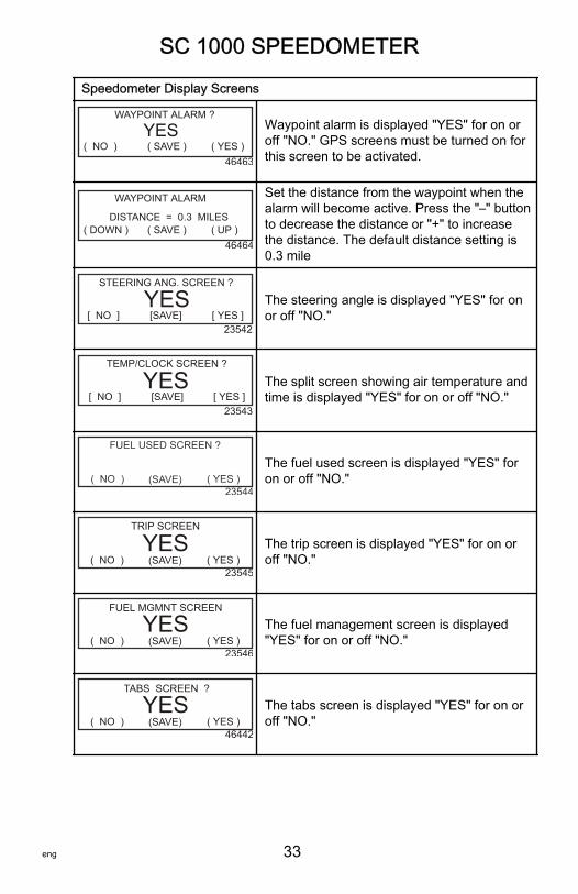
( NO ) ( SAVE ) ( YES )46463
WAYPOINT ALARM ?
YES Waypoint alarm is displayed "YES" for on oroff "NO." GPS screens must be turned on forthis screen to be activated.
( DOWN ) ( SAVE ) ( UP )46464
WAYPOINT ALARM
DISTANCE = 0.3 MILES
Set the distance from the waypoint when thealarm will become active. Press the "–" buttonto decrease the distance or "+" to increasethe distance. The default distance setting is0.3 mile
[ NO ] [SAVE] [ YES ]23542
STEERING ANG. SCREEN ?
YES The steering angle is displayed "YES" for onor off "NO."
23543
TEMP/CLOCK SCREEN ?
YES[ NO ] [SAVE] [ YES ]
The split screen showing air temperature andtime is displayed "YES" for on or off "NO."
( NO ) (SAVE) ( YES )23544
FUEL USED SCREEN ?
The fuel used screen is displayed "YES" foron or off "NO."
( NO ) (SAVE) ( YES )23545
TRIP SCREEN
YES The trip screen is displayed "YES" for on oroff "NO."
( NO ) (SAVE) ( YES )23546
FUEL MGMNT SCREEN
YES The fuel management screen is displayed"YES" for on or off "NO."
( NO ) (SAVE) ( YES )46442
TABS SCREEN ?
YES The tabs screen is displayed "YES" for on oroff "NO."
SC 1000 SPEEDOMETER
34 eng
Speedometer Display Screens
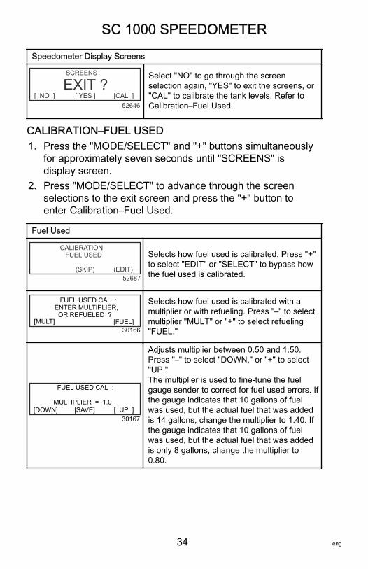
[ NO ] [ YES ] [CAL ]
SCREENS
EXIT ?52646
Select "NO" to go through the screenselection again, "YES" to exit the screens, or"CAL" to calibrate the tank levels. Refer toCalibration–Fuel Used.
CALIBRATION–FUEL USED1. Press the "MODE/SELECT" and "+" buttons simultaneously
for approximately seven seconds until "SCREENS" isdisplay screen.
2. Press "MODE/SELECT" to advance through the screenselections to the exit screen and press the "+" button toenter Calibration–Fuel Used.
Fuel Used
(SKIP) (EDIT)
CALIBRATION FUEL USED
52687
Selects how fuel used is calibrated. Press "+"to select "EDIT" or "SELECT" to bypass howthe fuel used is calibrated.
[FUEL]
FUEL USED CAL : ENTER MULTIPLIER, OR REFUELED ?
[MULT]30166
Selects how fuel used is calibrated with amultiplier or with refueling. Press "–" to selectmultiplier "MULT" or "+" to select refueling"FUEL."
[DOWN] [SAVE] [ UP ]
FUEL USED CAL : MULTIPLIER = 1.0
30167
Adjusts multiplier between 0.50 and 1.50.Press "–" to select "DOWN," or "+" to select"UP."The multiplier is used to fine‑tune the fuelgauge sender to correct for fuel used errors. Ifthe gauge indicates that 10 gallons of fuelwas used, but the actual fuel that was addedis 14 gallons, change the multiplier to 1.40. Ifthe gauge indicates that 10 gallons of fuelwas used, but the actual fuel that was addedis only 8 gallons, change the multiplier to0.80.
SC 1000 SPEEDOMETER
eng 35
Fuel Used
[DOWN] [SAVE] [ UP ]
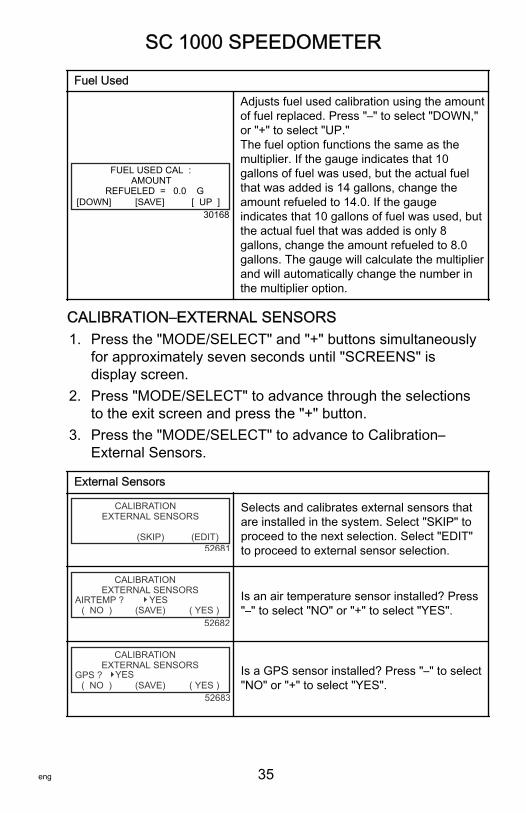
FUEL USED CAL : AMOUNT REFUELED = 0.0 G
30168
Adjusts fuel used calibration using the amountof fuel replaced. Press "–" to select "DOWN,"or "+" to select "UP."The fuel option functions the same as themultiplier. If the gauge indicates that 10gallons of fuel was used, but the actual fuelthat was added is 14 gallons, change theamount refueled to 14.0. If the gaugeindicates that 10 gallons of fuel was used, butthe actual fuel that was added is only 8gallons, change the amount refueled to 8.0gallons. The gauge will calculate the multiplierand will automatically change the number inthe multiplier option.
CALIBRATION–EXTERNAL SENSORS1. Press the "MODE/SELECT" and "+" buttons simultaneously
for approximately seven seconds until "SCREENS" isdisplay screen.
2. Press "MODE/SELECT" to advance through the selectionsto the exit screen and press the "+" button.
3. Press the "MODE/SELECT" to advance to Calibration–External Sensors.
External Sensors
(SKIP) (EDIT)
CALIBRATION EXTERNAL SENSORS
52681
Selects and calibrates external sensors thatare installed in the system. Select "SKIP" toproceed to the next selection. Select "EDIT"to proceed to external sensor selection.
(SAVE) ( YES )
CALIBRATION EXTERNAL SENSORS
( NO )AIRTEMP ? YES
52682
Is an air temperature sensor installed? Press"–" to select "NO" or "+" to select "YES".
(SAVE) ( YES )
CALIBRATION EXTERNAL SENSORS
( NO )GPS ? YES
52683
Is a GPS sensor installed? Press "–" to select"NO" or "+" to select "YES".
SC 1000 SPEEDOMETER
36 eng
External Sensors
(SAVE) ( YES )
CALIBRATION EXTERNAL SENSORS
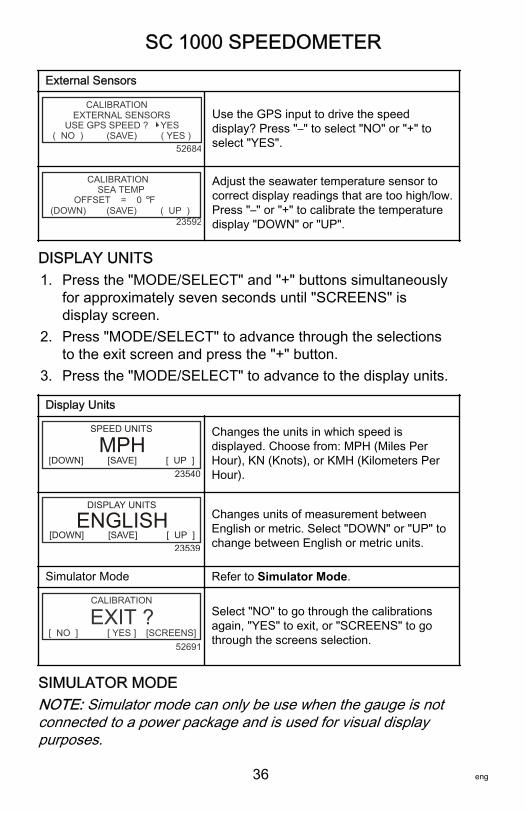
( NO ) USE GPS SPEED ? YES
52684
Use the GPS input to drive the speeddisplay? Press "–" to select "NO" or "+" toselect "YES".
(SAVE) ( UP )23592
CALIBRATION SEA TEMP
(DOWN)OFFSET = 0 F
Adjust the seawater temperature sensor tocorrect display readings that are too high/low.Press "–" or "+" to calibrate the temperaturedisplay "DOWN" or "UP".
DISPLAY UNITS1. Press the "MODE/SELECT" and "+" buttons simultaneously
for approximately seven seconds until "SCREENS" isdisplay screen.
2. Press "MODE/SELECT" to advance through the selectionsto the exit screen and press the "+" button.
3. Press the "MODE/SELECT" to advance to the display units.
Display Units
23540
SPEED UNITS
MPH[DOWN] [SAVE] [ UP ]
Changes the units in which speed isdisplayed. Choose from: MPH (Miles PerHour), KN (Knots), or KMH (Kilometers PerHour).
[DOWN] [SAVE] [ UP ]23539
DISPLAY UNITS
ENGLISH Changes units of measurement betweenEnglish or metric. Select "DOWN" or "UP" tochange between English or metric units.
Simulator Mode Refer to Simulator Mode.
[ NO ] [ YES ] [SCREENS]
CALIBRATION
EXIT ?52691
Select "NO" to go through the calibrationsagain, "YES" to exit, or "SCREENS" to gothrough the screens selection.
SIMULATOR MODENOTE: Simulator mode can only be use when the gauge is notconnected to a power package and is used for visual displaypurposes.
SC 1000 SPEEDOMETER
eng 37
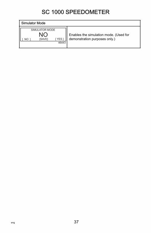
Simulator Mode
[ NO ] [ YES ][SAVE]46443
SIMULATOR MODE
NO Enables the simulation mode. (Used fordemonstration purposes only.)
TROLL CONTROL
38 eng
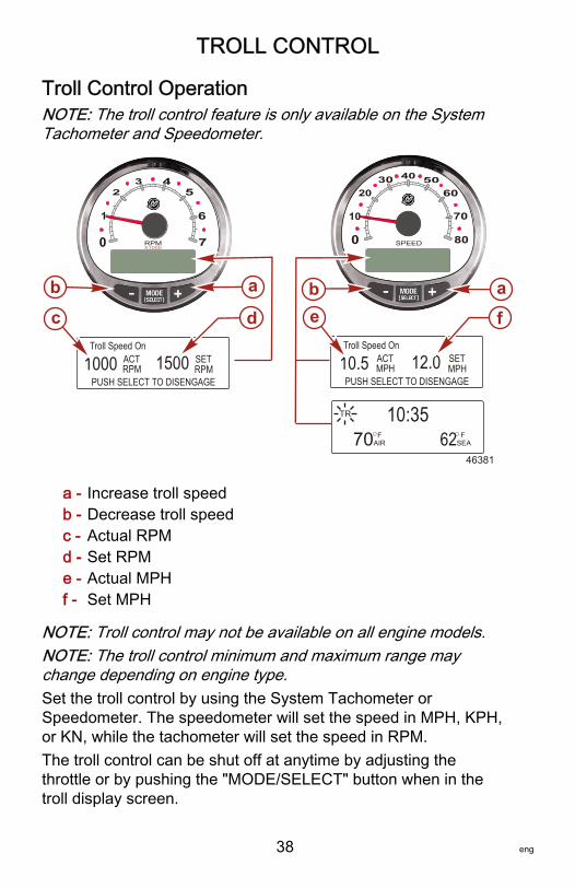
Troll Control OperationNOTE: The troll control feature is only available on the SystemTachometer and Speedometer.
a - Increase troll speedb - Decrease troll speedc - Actual RPMd - Set RPMe - Actual MPHf - Set MPH
NOTE: Troll control may not be available on all engine models.NOTE: The troll control minimum and maximum range maychange depending on engine type.Set the troll control by using the System Tachometer orSpeedometer. The speedometer will set the speed in MPH, KPH,or KN, while the tachometer will set the speed in RPM.The troll control can be shut off at anytime by adjusting thethrottle or by pushing the "MODE/SELECT" button when in thetroll display screen.
0
1
24
5
7
6
3
RPMX1000
0 SPEED
10
2030 40 50
60
70
80
a a
Troll Speed On
10.5 ACTMPH 12.0
PUSH SELECT TO DISENGAGE
SETMPH
feTroll Speed On
1000 ACTRPM 1500
PUSH SELECT TO DISENGAGE
SETRPM
dc
FAIR
FSEA70 62
10:35TR
b b
46381
TROLL CONTROL
eng 39
When the troll control is shut off, the system will remember theset speed. When the troll control is engaged, it will return to theset speed.The display screen will revert back to the previous screen afterfive seconds of inactivity. Push the "+" or "–" button to reactivatethe troll control display screen.When the troll control is engaged and not in the troll controldisplay screen, a flashing "TR" signal will appear in the upper leftcorner of the screen to indicate the troll control is still active.SETTING TROLL CONTROL
a - Increase troll set speedb - Decrease troll set speedc - Setting is too fast, reduce set troll speedd - Setting is too slow, increase set troll speede - Actual speedf - Set speed
1. With the engine running, shift the engine into gear. Set theengine speed at idle.
0
1
24
5
7
6
3
RPMX1000 0 SPEED
10
2030 40 50
60
70
80
600575PUSH SELECT TO DISENGAGE
TROLL SPEED ON OFFACTRPM
SETRPM
TROLL SPEED ON OFF
PUSH SELECT TO DISENGAGE
3.02.5 ACTMPH
SETMPH
SETMPH
TROLL SPEED TOO FAST
REDUCE TROLL SPEED
7.54.5 ACTMPH
SETMPH
TROLL SPEED TOO SLOW
INCREASE TROLL SPEED
3.02.5 ACTMPH
c d 46382
a afe
b b
TROLL CONTROL
40 eng
2. Push in either the "+" or "–" buttons to bring up the trollcontrol display screen.
3. Press "MODE/SELECT" to engage the troll control.4. Use the "+" and "–" buttons to set the desired speed. Use
"+" to increase the set speed and use "–" to decrease theset speed.
5. If the troll speed is set to a higher speed than the troll controlcan maintain, the "TROLL SPEED TOO FAST" display willappear. Reduce the set troll speed.
6. If the troll speed is set to a slower speed than the trollcontrol can maintain, the "TROLL SPEED TOO SLOW"display will appear. Increase the set troll speed.
CANCELING TROLL CONTROLThere are three ways to cancel the troll control:• Press the "MODE/SELECT" button when in the troll display
screen.• Move the throttle to a different speed.• Shift the engine into neutral.
SMART TOW
eng 41
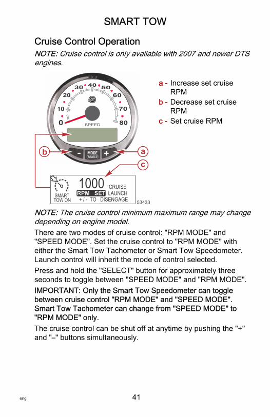
Cruise Control OperationNOTE: Cruise control is only available with 2007 and newer DTSengines.
a - Increase set cruiseRPM
b - Decrease set cruiseRPM
c - Set cruise RPM
NOTE: The cruise control minimum maximum range may changedepending on engine model.There are two modes of cruise control: "RPM MODE" and"SPEED MODE". Set the cruise control to "RPM MODE" witheither the Smart Tow Tachometer or Smart Tow Speedometer.Launch control will inherit the mode of control selected.Press and hold the "SELECT" button for approximately threeseconds to toggle between "SPEED MODE" and "RPM MODE".IMPORTANT: Only the Smart Tow Speedometer can togglebetween cruise control "RPM MODE" and "SPEED MODE".Smart Tow Tachometer can change from "SPEED MODE" to"RPM MODE" only.The cruise control can be shut off at anytime by pushing the "+"and "–" buttons simultaneously.
0 SPEED
10
2030 40 50
60
70
80
b a
SMART TOW ON
1000 CRUISELAUNCH
+ / - TO DISENGAGERPM SET
c
53433
SMART TOW
42 eng
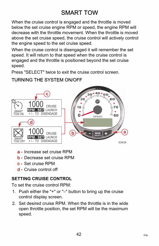
When the cruise control is engaged and the throttle is movedbelow the set cruise engine RPM or speed, the engine RPM willdecrease with the throttle movement. When the throttle is movedabove the set cruise speed, the cruise control will actively controlthe engine speed to the set cruise speed.When the cruise control is disengaged it will remember the setspeed. It will return to that speed when the cruise control isengaged and the throttle is positioned beyond the set cruisespeed.Press "SELECT" twice to exit the cruise control screen.
TURNING THE SYSTEM ON/OFF
a - Increase set cruise RPMb - Decrease set cruise RPMc - Set cruise RPMd - Cruise control off
SETTING CRUISE CONTROLTo set the cruise control RPM:1. Push either the "+" or "–" button to bring up the cruise
control display screen.2. Set desired cruise RPM. When the throttle is in the wide
open throttle position, the set RPM will be the maximumspeed.
0 SPEED
10
2030 40 50
60
70
80
b a
SMART TOW ON
1000 CRUISELAUNCH
+ / - TO DISENGAGERPM SET
c
SMART TOW OFF
1000 CRUISELAUNCH
+ / - TO DISENGAGERPM SET
d
53434
SMART TOW
eng 43
3. Push "+" and "–" button simultaneously to engage the cruisecontrol.
NOTE: The cruise control must be engaged for both gauges todisplay the active cruise control setting.CANCELING CRUISE CONTROLTo cancel the cruise control: press the "+" and "–" buttonssimultaneously.
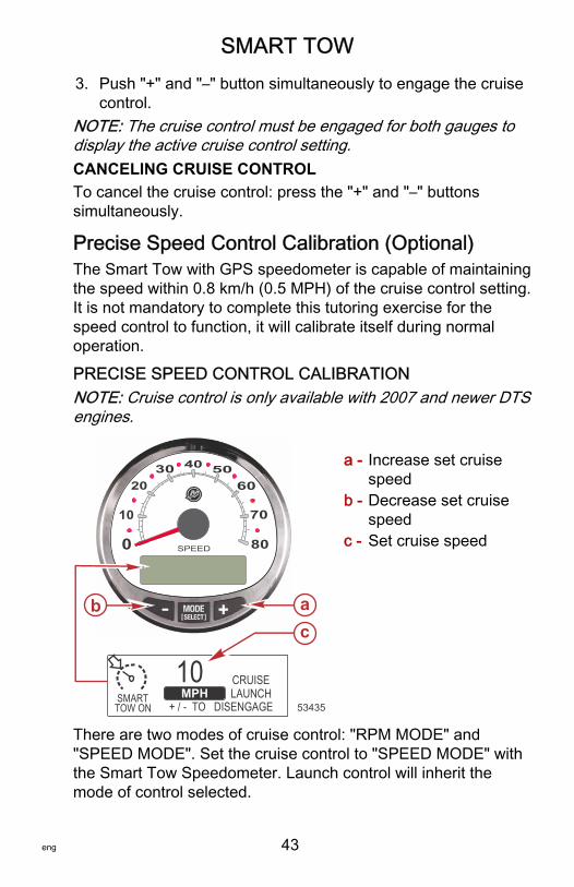
Precise Speed Control Calibration (Optional)The Smart Tow with GPS speedometer is capable of maintainingthe speed within 0.8 km/h (0.5 MPH) of the cruise control setting.It is not mandatory to complete this tutoring exercise for thespeed control to function, it will calibrate itself during normaloperation.
PRECISE SPEED CONTROL CALIBRATIONNOTE: Cruise control is only available with 2007 and newer DTSengines.
a - Increase set cruisespeed
b - Decrease set cruisespeed
c - Set cruise speed
There are two modes of cruise control: "RPM MODE" and"SPEED MODE". Set the cruise control to "SPEED MODE" withthe Smart Tow Speedometer. Launch control will inherit themode of control selected.
0 SPEED
10
2030 40 50
60
70
80
b a
SMART TOW ON
10 CRUISELAUNCH
+ / - TO DISENGAGEMPH
c
53435
SMART TOW
44 eng
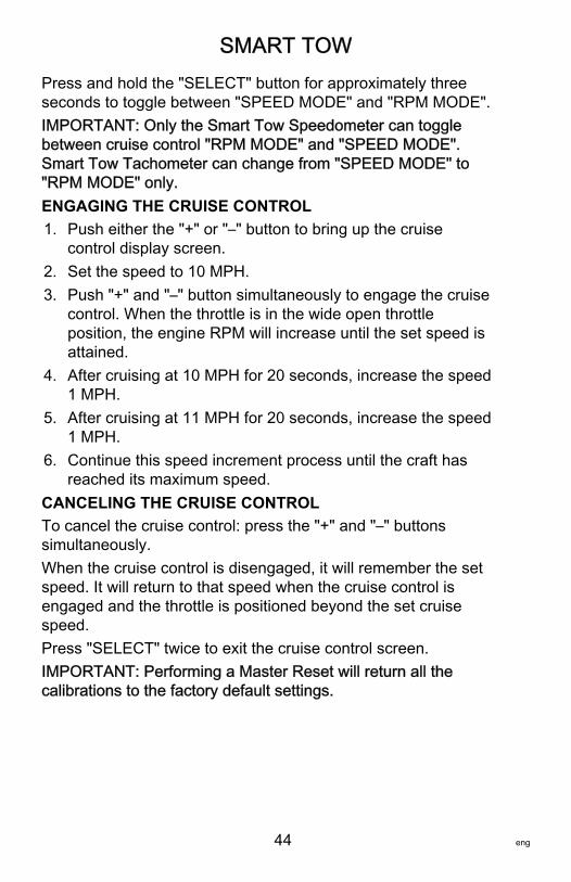
Press and hold the "SELECT" button for approximately threeseconds to toggle between "SPEED MODE" and "RPM MODE".IMPORTANT: Only the Smart Tow Speedometer can togglebetween cruise control "RPM MODE" and "SPEED MODE".Smart Tow Tachometer can change from "SPEED MODE" to"RPM MODE" only.ENGAGING THE CRUISE CONTROL1. Push either the "+" or "–" button to bring up the cruise
control display screen.2. Set the speed to 10 MPH.3. Push "+" and "–" button simultaneously to engage the cruise
control. When the throttle is in the wide open throttleposition, the engine RPM will increase until the set speed isattained.
4. After cruising at 10 MPH for 20 seconds, increase the speed1 MPH.
5. After cruising at 11 MPH for 20 seconds, increase the speed1 MPH.
6. Continue this speed increment process until the craft hasreached its maximum speed.
CANCELING THE CRUISE CONTROLTo cancel the cruise control: press the "+" and "–" buttonssimultaneously.When the cruise control is disengaged, it will remember the setspeed. It will return to that speed when the cruise control isengaged and the throttle is positioned beyond the set cruisespeed.Press "SELECT" twice to exit the cruise control screen.IMPORTANT: Performing a Master Reset will return all thecalibrations to the factory default settings.
SMART TOW
eng 45
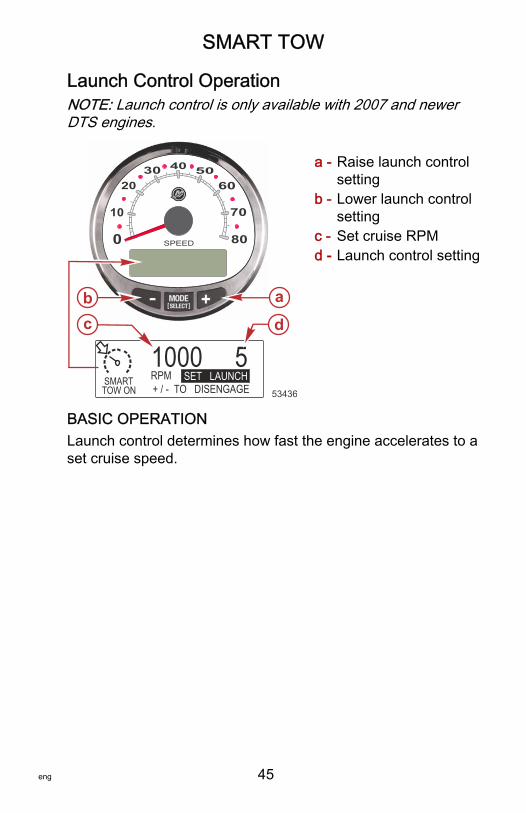
Launch Control OperationNOTE: Launch control is only available with 2007 and newerDTS engines.
a - Raise launch controlsetting
b - Lower launch controlsetting
c - Set cruise RPMd - Launch control setting
BASIC OPERATIONLaunch control determines how fast the engine accelerates to aset cruise speed.
0 SPEED
10
2030 40 50
60
70
80
SMART TOW ON
1000 5+ / - TO DISENGAGERPM SET LAUNCH
b a
dc
53436
SMART TOW
46 eng
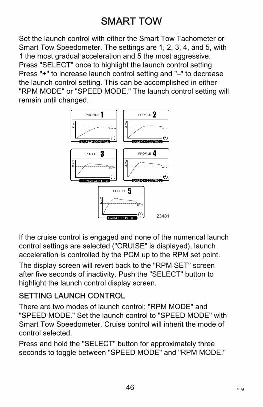
Set the launch control with either the Smart Tow Tachometer orSmart Tow Speedometer. The settings are 1, 2, 3, 4, and 5, with1 the most gradual acceleration and 5 the most aggressive.Press "SELECT" once to highlight the launch control setting.Press "+" to increase launch control setting and "–" to decreasethe launch control setting. This can be accomplished in either"RPM MODE" or "SPEED MODE." The launch control setting willremain until changed.
23481
If the cruise control is engaged and none of the numerical launchcontrol settings are selected ("CRUISE" is displayed), launchacceleration is controlled by the PCM up to the RPM set point.The display screen will revert back to the "RPM SET" screenafter five seconds of inactivity. Push the "SELECT" button tohighlight the launch control display screen.
SETTING LAUNCH CONTROLThere are two modes of launch control: "RPM MODE" and"SPEED MODE." Set the launch control to "SPEED MODE" withSmart Tow Speedometer. Cruise control will inherit the mode ofcontrol selected.Press and hold the "SELECT" button for approximately threeseconds to toggle between "SPEED MODE" and "RPM MODE."
SMART TOW
eng 47
IMPORTANT: Only the Smart Tow Speedometer can togglebetween cruise control "RPM MODE" and "SPEED MODE."Smart Tow Tachometer can change from "SPEED MODE" to"RPM MODE" only.1. Press "+" or "–" to bring up the cruise control display screen.2. Push the "SELECT" button to highlight "SET LAUNCH."3. Push "+" to raise the setting and push "–" to lower the
setting.4. Launch control will automatically turn on with the cruise
control.If the cruise control is engaged and none of the numerical orcustomized launch control settings are selected ("CRUISE" isdisplayed), launch acceleration is controlled by the throttle up tothe RPM set point.The display screen will revert back to the "RPM SET" screenafter five seconds of inactivity. Push the "SELECT" button tohighlight the "SET LAUNCH."
CANCELING LAUNCH CONTROLThe launch control will turn off when the cruise control is turnedoff.
Creating a Customized Launch SettingBeyond launch setting number 5 are eight customized launchsettings. Each customized launch setting name can have up toseven alpha characters to identify the custom launch. Thecustom launch setting can be controlled by RPM or speed. Touse the speed setting control, GPS must be interfaced with theSmartCraft gauge through a junction box.NOTE: If the Smart Tow set point is changed while thecustomized launch is active, the set point will automatically besaved for that user .1. Press the "SELECT" button to highlight "SET LAUNCH."2. Advance the launch control setting beyond number 5. After
number 5 the "NEW USER" launch control setting willactivate.
SMART TOW
48 eng
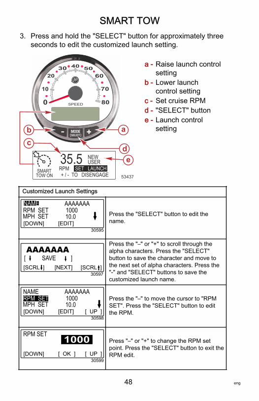
3. Press and hold the "SELECT" button for approximately threeseconds to edit the customized launch setting.
a - Raise launch controlsetting
b - Lower launchcontrol setting
c - Set cruise RPMd - "SELECT" buttone - Launch control
setting
Customized Launch Settings
AAAAAAARPM SETNAME
MPH SET100010.0
[DOWN] [EDIT]30595
Press the "SELECT" button to edit thename.
AAAAAAA [ SAVE ][SCRL ] [NEXT]
30597[SCRL ]
Press the "–" or "+" to scroll through thealpha characters. Press the "SELECT"button to save the character and move tothe next set of alpha characters. Press the"‑" and "SELECT" buttons to save thecustomized launch name.
AAAAAAANAME
MPH SET100010.0
[DOWN] [EDIT]30598
RPM SET
[ UP ]
Press the "–" to move the cursor to "RPMSET". Press the "SELECT" button to editthe RPM.
RPM SET
[DOWN] [ OK ]30599
[ UP ]
Press "–" or "+" to change the RPM setpoint. Press the "SELECT" button to exit theRPM edit.
0 SPEED
10
2030 40 50
60
70
80
SMART TOW ON
35.5+ / - TO DISENGAGE
b a
dc
RPM SET LAUNCHeUSER
NEW
53437
SMART TOW
eng 49
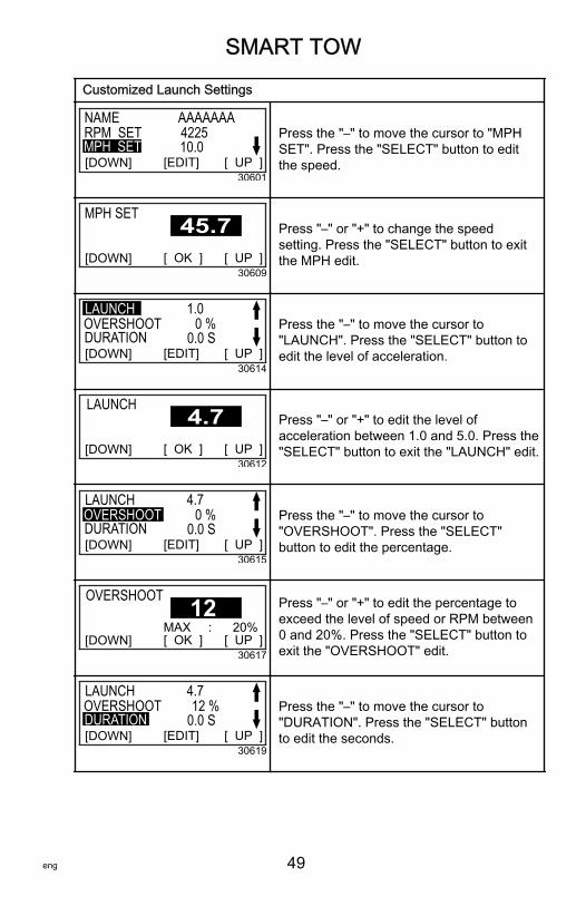
Customized Launch Settings
AAAAAAANAME422510.0
[DOWN] [EDIT]30601
RPM SET
[ UP ]MPH SET
Press the "–" to move the cursor to "MPHSET". Press the "SELECT" button to editthe speed.
MPH SET
[DOWN] [ OK ]30609
[ UP ]
Press "–" or "+" to change the speedsetting. Press the "SELECT" button to exitthe MPH edit.
1.00 %
0.0 S[DOWN] [EDIT]
30614[ UP ]
LAUNCHOVERSHOOTDURATION
Press the "–" to move the cursor to"LAUNCH". Press the "SELECT" button toedit the level of acceleration.
LAUNCH
[DOWN] [ OK ]30612
[ UP ]
Press "–" or "+" to edit the level ofacceleration between 1.0 and 5.0. Press the"SELECT" button to exit the "LAUNCH" edit.
4.70 %
0.0 S[DOWN] [EDIT]
30615[ UP ]
LAUNCHOVERSHOOTDURATION
Press the "–" to move the cursor to"OVERSHOOT". Press the "SELECT"button to edit the percentage.
OVERSHOOT
[DOWN] [ OK ]30617
[ UP ]MAX : 20%
12 Press "–" or "+" to edit the percentage toexceed the level of speed or RPM between0 and 20%. Press the "SELECT" button toexit the "OVERSHOOT" edit.
4.712 %
0.0 S[DOWN] [EDIT]
30619[ UP ]
LAUNCHOVERSHOOTDURATION
Press the "–" to move the cursor to"DURATION". Press the "SELECT" buttonto edit the seconds.
SMART TOW
50 eng
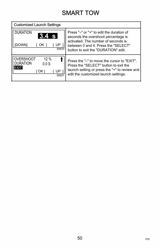
Customized Launch Settings
DURATION
[DOWN] [ OK ]30620
[ UP ]
3.4 sPress "–" or "+" to edit the duration ofseconds the overshoot percentage isactivated. The number of seconds isbetween 0 and 4. Press the "SELECT"button to exit the "DURATION" edit.
12 %0.0 S
[ OK ]30621
[ UP ]
OVERSHOOTDURATIONEXIT
Press the "–" to move the cursor to "EXIT".Press the "SELECT" button to exit thelaunch setting or press the "+" to review andedit the customized launch settings.


![Untitled-4 [] · SUPPLEMENTAL TYPE CERTIFICATE AVAILABILITY FOR THE "-1000 DIGITAL TACHOMETER Aerospatiale Air Tractor, Inc. Ayres Corp., Rockwell, Aero Commander](https://img.dokumen.tips/doc/110x75/5aecdd3b7f8b9a90318ed6f8/untitled-4-type-certificate-availability-for-the-1000-digital-tachometer-aerospatiale.jpg)