Embed Size (px)
Citation preview
SAP BW Extraction
Table of Contents1. Extraction................................................................................................................................................. 8
1.1Introduction .........................................................................................................................................8
1.2 Step-by-step control flow for a successful data extraction with SAP BW: .......................................12
2. Data Extraction from SAP Source Systems..........................................................................................12
2.1 Introduction ......................................................................................................................................12
2.1.1 Process .......................................................................................................................................13
2.1.2 Plug-in for R/3 Systems..............................................................................................................14
2.2 Transfer Method - PSA and IDoc.......................................................................................................14
2.2.1 Introduction ...............................................................................................................................14
2.2.2 Persistent Staging Area (PSA).....................................................................................................15
2.2.2.1 Definition ............................................................................................................................15
2.2.2.2 Use ......................................................................................................................................15
2.2.3 IDoc’s..........................................................................................................................................15
2.2.3.1 Definition ............................................................................................................................15
2.2.3.2 Example: .............................................................................................................................15
2.2.4 Two Methods to transfer data...................................................................................................15
2.2.4.1 Differences and advantages:...............................................................................................16
2.2.4.1.1 PSA ...............................................................................................................................16
2.2.4.2 ALE (data IDoc)................................................................................................................16
2.3 Data Source.......................................................................................................................................16
2.3.1 Assigning DataSources to InfoSources and Fields to InfoObjects..............................................17
2.3.2 Maintaining DataSources...........................................................................................................17
2.3.3 Transferring Business Content DataSources into Active Version ..............................................18
2.3.4 Extraction Structure ...................................................................................................................18
2.3.5 Transfer Structure ......................................................................................................................18
2.3.6 Replication of DataSources ........................................................................................................19
2.3.6.1 Replication of the Entire Metadata ....................................................................................19
2.3.6.2 Replication of the Application Component Hierarchy of a Source System ........................19
2.3.6.3 Replication of the Metadata ...............................................................................................19
2.3.6.4 Replication of a DataSource of a Source System ................................................................19
2.4 Data Extraction Logistics ...................................................................................................................20
2.4.1 Data extraction Illustration........................................................................................................20
2.4.1.1 Full Load:.............................................................................................................................20
2.4.1.2 Delta Load: ..........................................................................................................................22
2.5 LO Cockpit Functions.........................................................................................................................23
2.5.1 Maintain Extract Structures .......................................................................................................23
2.5.2 Maintain Data Sources...............................................................................................................23
2.5.3 Activating update.......................................................................................................................24
2.5.4 Controlling update .....................................................................................................................24
2.5.5 Setup Tables...............................................................................................................................24
2.5.6 Serialized V3...............................................................................................................................24
2.5.7 Queued Delta (the third update method)..................................................................................25
2.5.8 Direct Delta ( 2nd delta update method in our list) ....................................................................25
2.5.9 Unserialized V3: (The last one) ..................................................................................................25
2.6 LO Data Sources Data Flow in R/3 :...................................................................................................25
2.6.1 Filling up the Appended Structure.............................................................................................30
2.6.2 Regenerate & Check the Customized Objects ...........................................................................34
2.7 Structure of Delta Method for LO Cockpit Data Sources..................................................................36
2.7.1 Delta Management in extraction...............................................................................................36
2.7.2 Step-by-Step Maintenance ........................................................................................................37
2.8 Delta Method....................................................................................................................................46
2.8.1 Master Data ...............................................................................................................................46
2.8.2 TRANSACTIONAL DATA ..............................................................................................................47
2.8.3 Delta Process..............................................................................................................................48
2.9 Delta Method Properties ..................................................................................................................49
2.9.1 Delta Initialization ......................................................................................................................49
2.9. 2 Delta Extraction.........................................................................................................................49
2.9.3 Update Modes ...........................................................................................................................50
2.9.3.1 V1 Update ...........................................................................................................................50
2.9.3.2 V2 Update ...........................................................................................................................51
2.9.3.3 V3 Update ...........................................................................................................................51
2.10 Delta Queue Functions....................................................................................................................51
2.10.1 Direct Delta (V1 update) ..........................................................................................................52
2.10.2 Queued delta (V1 + V3 updates)..............................................................................................53
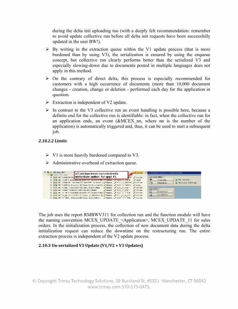
2.10.2.1 Benefits .............................................................................................................................53
2.10.2.2 Limits.................................................................................................................................54
2.10.3 Un-serialized V3 Update (V1/V2 + V3 Updates) ......................................................................54
2.11 Generic extraction...........................................................................................................................55
2.11.1Create Generic extraction [Master data]..................................................................................56
2.12 Generic Data Types .........................................................................................................................59
2.12.1 Master Data .............................................................................................................................59
2.12.1.1. Texts.................................................................................................................................59
2.12.1.2. Attributes .........................................................................................................................59
2.12.1.3. Hierarchies .......................................................................................................................59
2.12.2 Functions..................................................................................................................................59
2.12.2.1 Time-dependent Attributes ..............................................................................................59
2.12.2.2 Time-dependent Texts ......................................................................................................59
2.12.2.3 Time-dependent Texts and Attributes..............................................................................60
2.12.2.4 Language-dependent Texts...............................................................................................60
2.12.3 Transactional data....................................................................................................................60
2.13 Generic Data sources ......................................................................................................................61
2.13.1 Extraction Structure .................................................................................................................62
2.13.2 Editing the DataSource in the Source System..........................................................................62
2.13.3 Replication of DataSources......................................................................................................62
2.13.3.1 Replication Process Flow ..................................................................................................62
2.13.3.2 Deleting DataSources during Replication .........................................................................63
2.13.3.3 Automatic Replication during Data Request.....................................................................63
2.14 Enhancing Business Content...........................................................................................................63
3. Extraction with Flat Files ......................................................................................................................69
3.1 Data from Flat Files (7.0)...................................................................................................................69
3.2 Data from Flat Files (3.x) ...................................................................................................................70
3.3 Extracting Transaction and Master Data using Flat Files ..................................................................70
3.4 Data Types that can be extracted using Flat Files.............................................................................86
3.4.1 Basic Steps of Data Flow (ETL process): .....................................................................................87
3.4.2 Step-by-Step to upload Master Data from Flat File to InfoObjects ...........................................87
4. DB Connect...........................................................................................................................................106
4.1 Introduction ....................................................................................................................................106
4.2 Loading data from SAP Supporting DBMS into BI...........................................................................107
4.2.1 Process Description..................................................................................................................107
5. Universal Data Integration .................................................................................................................130
5.1 Introduction ....................................................................................................................................130
5.2 Process Flow....................................................................................................................................130
5.3 Creating UD source system.............................................................................................................130
5.4 Creating a DataSource for UD Connect...........................................................................................131
5.5 Using Relational UD Connect Sources (JDBC) .................................................................................133
5.5.1 Aggregated Reading and Quantity Restriction ........................................................................133
5.5.2 Use of Multiple Database Objects as UD Connect Source Object ...........................................133
5.6 BI JDBC Connector...........................................................................................................................133
5.6.1 Deploy the user data source’s JDBC driver to the server: .......................................................134
5.6.2 Configuring BI Java Connector ...............................................................................................134
5.6.2.1 Testing the Connections................................................................................................135
5.6.2.2 JNDI Names ..................................................................................................................135
5.6.2.3 Cloning the Connections ...............................................................................................135
5.6.3 Connector Properties................................................................................................................135
5.7 BI XMLA Connector .........................................................................................................................137
5.7.1 Using InfoObjects with UD Connect.........................................................................................138
5.7.2 Using SAP Namespace for Generated Objects.........................................................................139
6. XML Integration...................................................................................................................................140
6.1 Introduction ....................................................................................................................................140
6.2 Benefits of XML Integration............................................................................................................140
6.2.1 End-to-End Web Business Processes .......................................................................................140
6.2.2 Open Business Document Exchange over the Internet ...........................................................141
6.2.3 XML Solutions for SAP services ................................................................................................141
6.3 Business Integration with XML .......................................................................................................141
6.3.1 Incorporating XML Standards ..................................................................................................142
6.3.2 SAP’s Internet Business Framework ........................................................................................142
6.3.3 SAP applications with XML.......................................................................................................143
6.3.4 Factors leading to emergence of XML-enabled SAP solutions ................................................144
6.3.4.1 Changing Business Standards and their adoption ............................................................144
6.3.4.2 Internet Security Standards ..............................................................................................144
6.4 Web-based business solutions........................................................................................................144
6.4.1 Components of Business Connector........................................................................................144
6.5 How to Customize Business Connector (BC)...................................................................................145
6.5.1 Add New Users to BC ...............................................................................................................145
6.5.2 Add SAP Systems......................................................................................................................145
6.5.3 Add Router Tables....................................................................................................................146
6.5.4 Access functionality in the Business Connector.......................................................................146
7. Data Mart Interface .............................................................................................................................147
7.1 Introduction ....................................................................................................................................147
7.2 Special Features ..............................................................................................................................147
7.3 Data Mart Interface in the Myself System......................................................................................148
7.4 Data Mart Interface between Several Systems ..............................................................................148
7.4.1 Architectures............................................................................................................................149
7.4.1.1 Replicating Architecture....................................................................................................149
7.4.1.2 Aggregating Architecture..................................................................................................150
7.4.2 Process Flow.............................................................................................................................151
7.4.2.1 In the Source BI.................................................................................................................151
7.4.2.2 In the Target BI..................................................................................................................151
7.4.3 Generating Export DataSources for InfoProviders...................................................................152
7.4.4 Generating Master Data Export DataSources..........................................................................152
7.4.5 Transactional Data Transfer Using the Data Mart Interface....................................................153
7.4.5.1 Delta Process.....................................................................................................................153
7.4.5.2 Restriction.........................................................................................................................153
7.4.6 Transferring Texts and Hierarchies for the Data Mart Interface .............................................153
7. Virtual InfoCubes.................................................................................................................................154
7.1 Introduction ....................................................................................................................................154
7.2 Create Virtual Infocube...................................................................................................................154
7.3 Different Types................................................................................................................................154
7.3.1 SAP RemoteCube .....................................................................................................................155
7.3.1.1 Creating a SAP RemoteCube.............................................................................................155
7.3.1.2 Structure ...........................................................................................................................156
7.3.1.3 Integration ........................................................................................................................156
7.3.2 Remote Cube............................................................................................................................156
7.3.2.1 Structure ...........................................................................................................................157
7.3.2.2 Integration ........................................................................................................................157
7.3.3 Virtual InfoCubes with Services ...............................................................................................158
7.3.3.1 Structure ...........................................................................................................................158
7.3.3.2 Dependencies....................................................................................................................159
7.3.3.2.1 Description of the interfaces for user-defined function modules .............................160
7.3.3.2.2 Additional parameters for variant 2 for transferring hierarchy restrictions .............161
7.3.3.3 Method for determining the correct variant for the interface.........................................161
1. Extraction
1.1Introduction
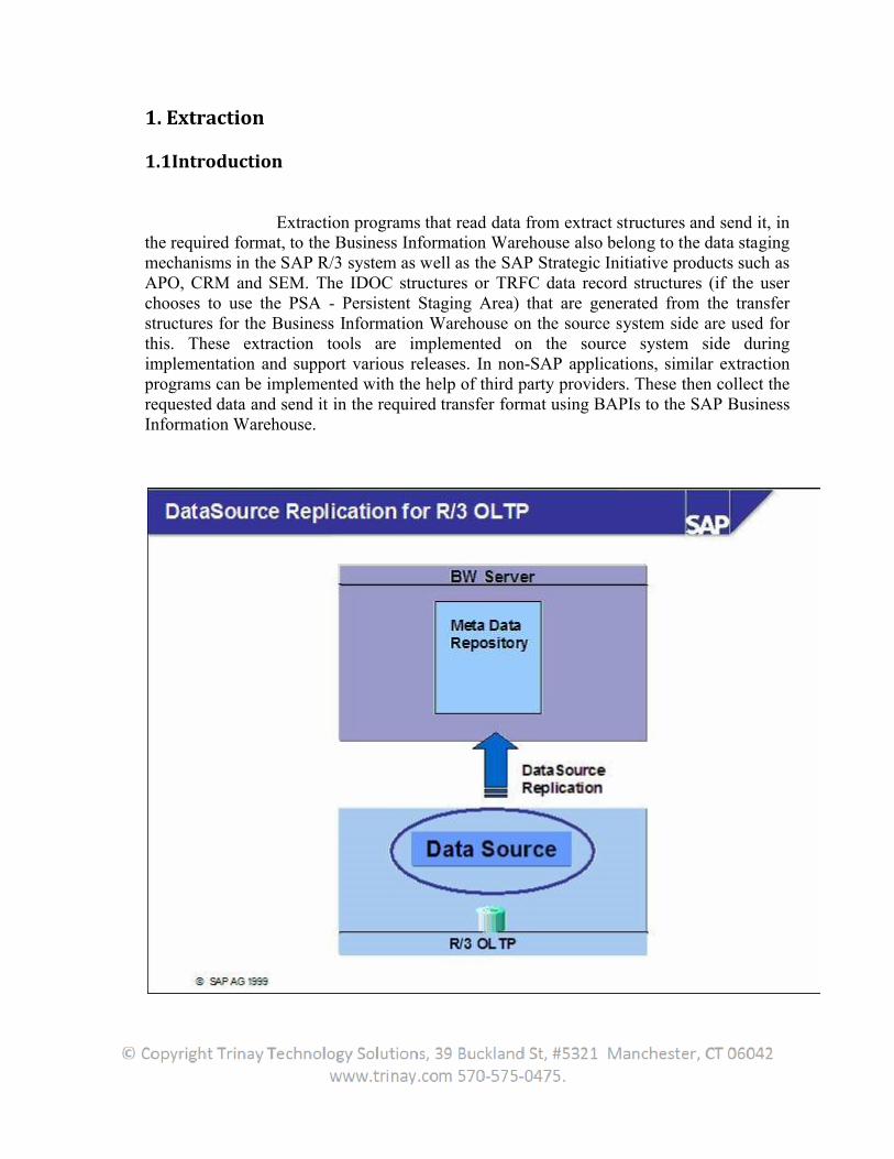
Extraction programs that read data from extract structures and send it, in the required format, to the Business Information Warehouse also belong to the data staging mechanisms in the SAP R/3 system as well as the SAP Strategic Initiative products such as APO, CRM and SEM. The IDOC structures or TRFC data record structures (if the userchooses to use the PSA - Persistent Staging Area) that are generated from the transfer structures for the Business Information Warehouse on the source system side are used for this. These extraction tools are implemented on the source system side during implementation and support various releases. In non-SAP applications, similar extraction programs can be implemented with the help of third party providers. These then collect the requested data and send it in the required transfer format using BAPIs to the SAP Business Information Warehouse.
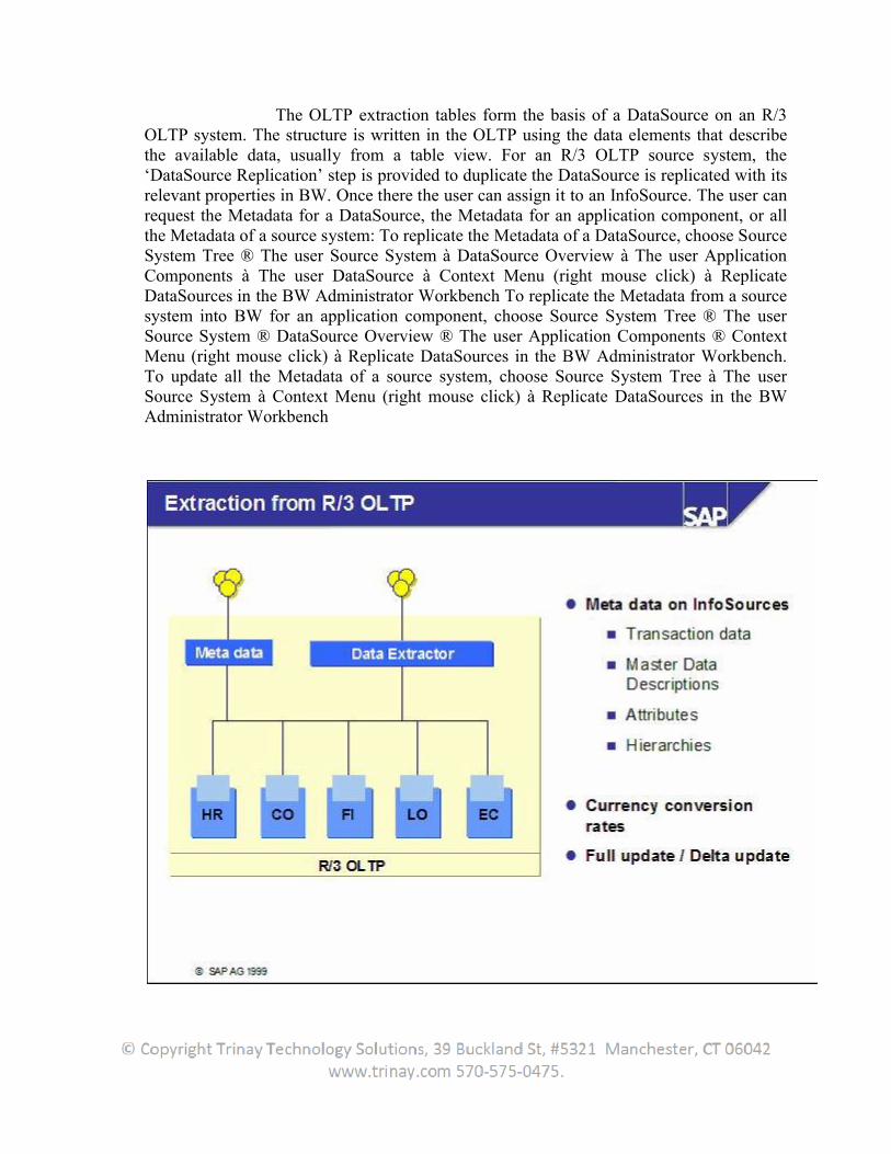
The OLTP extraction tables form the basis of a DataSource on an R/3 OLTP system. The structure is written in the OLTP using the data elements that describe the available data, usually from a table view. For an R/3 OLTP source system, the ‘DataSource Replication’ step is provided to duplicate the DataSource is replicated with its relevant properties in BW. Once there the user can assign it to an InfoSource. The user can request the Metadata for a DataSource, the Metadata for an application component, or all the Metadata of a source system: To replicate the Metadata of a DataSource, choose Source System Tree ® The user Source System à DataSource Overview à The user Application Components à The user DataSource à Context Menu (right mouse click) à Replicate DataSources in the BW Administrator Workbench To replicate the Metadata from a source system into BW for an application component, choose Source System Tree ® The userSource System ® DataSource Overview ® The user Application Components ® Context Menu (right mouse click) à Replicate DataSources in the BW Administrator Workbench. To update all the Metadata of a source system, choose Source System Tree à The userSource System à Context Menu (right mouse click) à Replicate DataSources in the BW Administrator Workbench
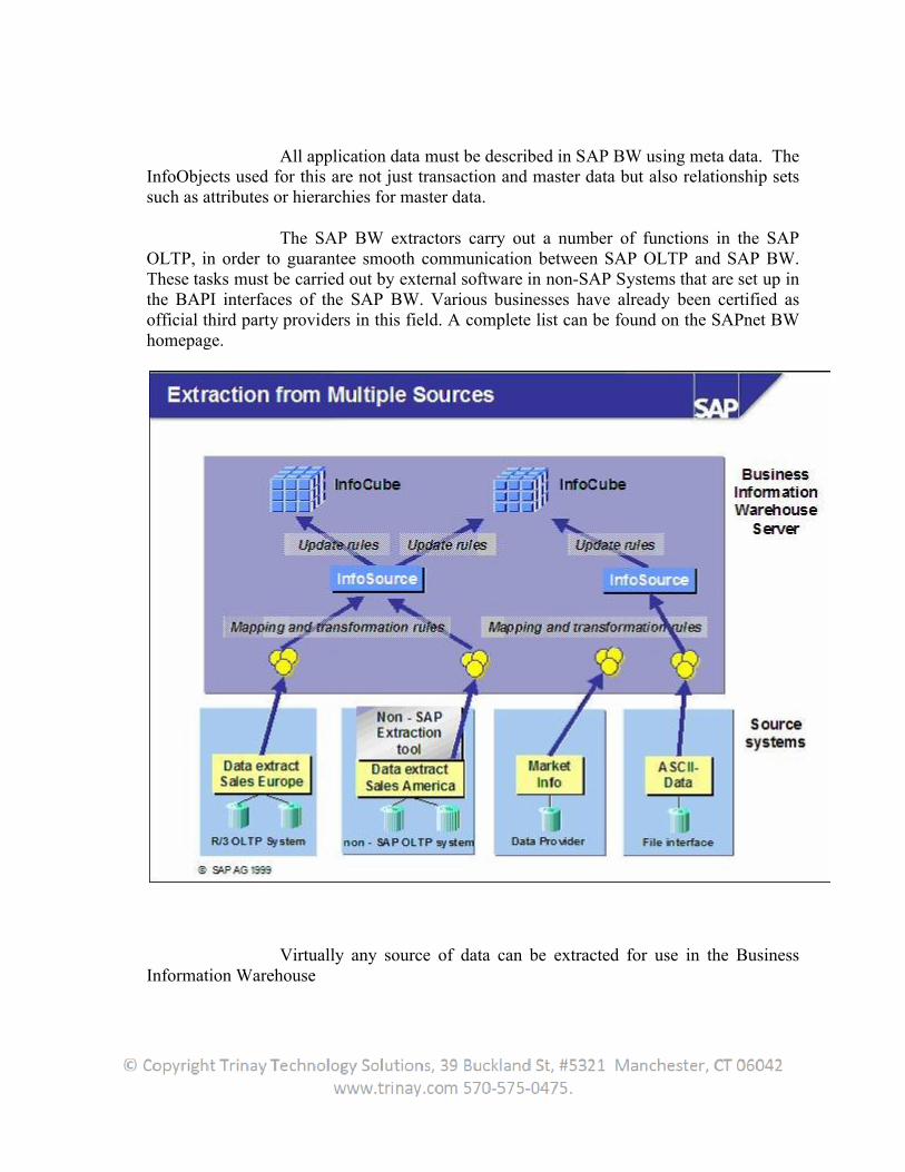
All application data must be described in SAP BW using meta data. The InfoObjects used for this are not just transaction and master data but also relationship sets such as attributes or hierarchies for master data.
The SAP BW extractors carry out a number of functions in the SAP OLTP, in order to guarantee smooth communication between SAP OLTP and SAP BW. These tasks must be carried out by external software in non-SAP Systems that are set up in the BAPI interfaces of the SAP BW. Various businesses have already been certified as official third party providers in this field. A complete list can be found on the SAPnet BW homepage.
Virtually any source of data can be extracted for use in the Business Information Warehouse
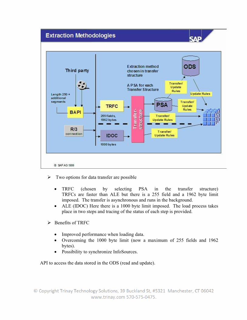
Two options for data transfer are possible
TRFC (chosen by selecting PSA in the transfer structure)TRFCs are faster than ALE but there is a 255 field and a 1962 byte limit imposed. The transfer is asynchronous and runs in the background.
ALE (IDOC) Here there is a 1000 byte limit imposed. The load process takes place in two steps and tracing of the status of each step is provided.
Benefits of TRFC
Improved performance when loading data. Overcoming the 1000 byte limit (now a maximum of 255 fields and 1962
bytes). Possibility to synchronize InfoSources.
API to access the data stored in the ODS (read and update).
1.2 Step-by-step control flow for a successful data extraction with SAP BW:
1. An InfoPackage is scheduled for execution at a specific point of time or for a certain system- or user-defined event.
2. Once the defined point of time is reached, the SAP BW system starts a batch job that sends a request IDoc to the SAP source system.
3. The request IDoc arrives in the source system and is processed by the IDoc dispatcher, which calls the BI Service API to process the request.
4. The BI Service API checks the request for technical consistency. Possible error conditions include specification of DataSources unavailable in the source system and changes in the DataSource setup or the extraction process that have not yet been replicated to the SAP BW system.
5. The BI Service API calls the extractor in initialization mode to allow for extractor-specific initializations before actually starting the extraction process. The generic extractor, for example, opens an SQL cursor based on the specified DataSource and selection criteria.
6. The BI Service API calls the extractor in extraction mode. One data package per call is returned to the BI Service API, and customer exits are called for possible enhancements. The extractor takes care of splitting the complete result set into data packages according to the IDoc control parameters. The BI Service API continues to call the extractor until no more data can be fetched.
7. The BI Service API finally sends a final status IDoc notifying the target system that request processing has finished (successfully or with errors specified in the status IDoc).
2. Data Extraction from SAP Source Systems
2.1 Introduction
Extractors are one of the data retrieval mechanisms in the SAP source system. An extractor can fill the extract structure of a DataSource with the data from SAP source system datasets.
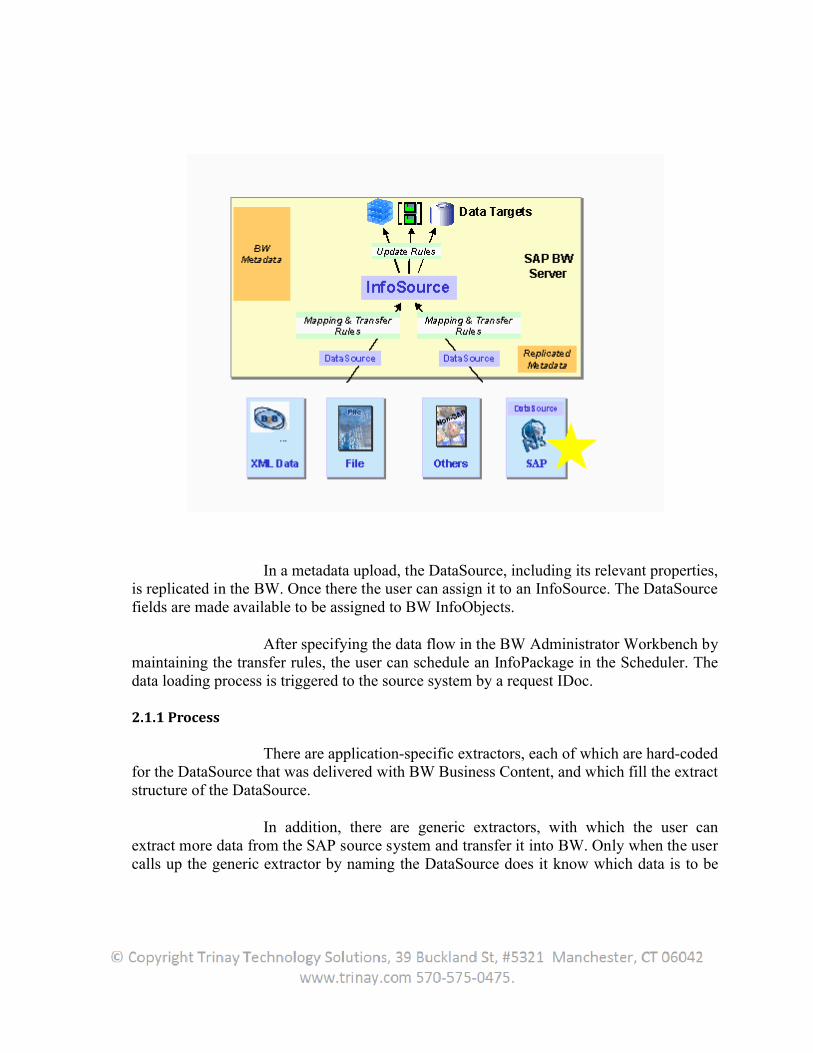
In a metadata upload, the DataSource, including its relevant properties, is replicated in the BW. Once there the user can assign it to an InfoSource. The DataSource fields are made available to be assigned to BW InfoObjects.
After specifying the data flow in the BW Administrator Workbench by maintaining the transfer rules, the user can schedule an InfoPackage in the Scheduler. The data loading process is triggered to the source system by a request IDoc.
2.1.1 Process
There are application-specific extractors, each of which are hard-coded for the DataSource that was delivered with BW Business Content, and which fill the extract structure of the DataSource.
In addition, there are generic extractors, with which the user can extract more data from the SAP source system and transfer it into BW. Only when the usercalls up the generic extractor by naming the DataSource does it know which data is to be
extracted, and from which tables it should read it from and in which structure. This is how it fills different extract structures and DataSources.
The user can run generic data extraction in the R/3 source system application areas such as LIS, CO-PA, FI-SL and HR. This is how LIS, for example, uses generic extraction to read info structures. DataSources are generated on the basis of these(individually) defined info structures. We speak of customer-defined DataSources with generic data extraction from applications.
Regardless of application, the user can generically extract master data attributes or -texts, or transaction data from all transparent tables, database views or SAP query functional areas or using the function module. The user can generate user-specific DataSources here. In this case, we speak of generic DataSources.
The DataSource data for these types are read generically and transferred into the BW. This is how generic extractors allow the extraction of data that cannot be made available within the framework of Business Content.
The user can find further information in the implementation guide to data extraction from SAP source systems. The user get there by choosing The user Source System Context Menu (right mouse click) Customizing Extractors in the BW Administrator Workbench – Modeling.
2.1.2 Plug-in for R/3 Systems
BW-specific source system functions, extractors and DataSources are delivered by so-called plug-ins.Communication between the R/3 source system and the SAP Business Information Warehouse is only possible if the appropriate plug-in is installed in the source system.
2.2 Transfer Method - PSA and IDoc
2.2.1 Introduction
This information is taken from sap.help.com and some other sources as well and rearranged to understand this concept much better. If time permits, we will discuss this in the class in details.
2.2.2 Persistent Staging Area (PSA)
2.2.2.1 Definition
The Persistent Staging Area (PSA) is the initial storage area for requested transaction data, master data attributes, and texts from various source systems within the Business Information Warehouse.
2.2.2.2 Use
The requested data is stored in transparent, relational database tables. It is stored in the form of the transfer structure and is not modified in any way, which means that if the data contained errors in the source system, it may still contain errors. When the user load flat files, the data does not remain completely unchanged, since it may be modified by conversion routines (for example, the date format 31.12.1999 might be converted to 19991231 in order to ensure the uniformity of the data). The user can check the quality of the requests, their usefulness, the sequence in which they are arranged, and how complete they are.
2.2.3 IDoc’s
2.2.3.1 Definition
The IDoc interface exchanges business data with an external system. The IDoc interface consists of the definition of a data structure, along with processing logic for this data structure. The business data is saved in IDoc format in the IDoc Interface and is forwarded as IDocs. If an error occurs, exception handling is triggered using SAP tasks. The agents who are responsible for these tasks and have the relevant authorizations are defined in the IDoc Interface. Standard SAP format for electronic data interchange between systems (Intermediate Document).Different message types (for example, delivery confirmations or purchase orders) normally represent the different specific formats, known as IDoc types. Multiple message types with related content can be assigned to one IDoc type.
2.2.3.2 Example:
The IDoc type ORDERS01 transfers the logical message types ORDERS (purchase order) and ORDRSP (order confirmation).Among other areas, IDocs are used in both Electronic Data Interchange (EDI) and for data distribution in a system group (ALE).
2.2.4 Two Methods to transfer data
Basically, there are two transfer methods for SAP systems:
With the IDoc method, IDoc interface technology is used to pack the data into IDoc containers.
With the PSA transfer method, IDoc containers are not used to send the data. Instead, the data is transferred directly in the form of a transfer structure.Information is sent from the source system (no data) through the Idoc interface (info IDocs). This information can be, for example, the number of data records extracted or information on the monitor.
2.2.4.1 Differences and advantages:
2.2.4.1.1 PSA
1. Data record length Max. 1962 bytes.2. Number of fields per data record: Restricted to 2553. Uses TRFC as transfer log.4. Advantage: Improved performance since larger data packages can be transported. Error handling is possible.5. More common technology since it brings with it a better load performance and gives the user the option of using the PSA as an inbound data store (For Master and Transaction data).
2.2.4.2 ALE (data IDoc)
1. Data record length Max.1000 bytes.2. Uses TRFC as transfer log3. Uses Info-IDocs: Uses info and data IDocs.4. Advantage: More detailed log through control record and status record for data IDoc.5. Use with hierarchies.
The user will not be able to view the data in IDoc's while transferring the data. The most advantageous thing about PSA is that we can see and do any editing if there is any error in the records which means that we are able to view the data. That is not the case with IDoc’s.
2.3 Data Source
Data that logically belongs together is stored in the source system in the form of DataSources. A DataSource consists of a quantity of fields that are offered for data transfer into BW. The DataSource is technically based on the fields of the extraction structure. By defining a DataSource, these fields can be enhanced as well as hidden (or filtered) for the data transfer. It also describes the properties of the extractor belonging to it,
as regards the data transfer into BW. During a Metadata upload, the properties of the DataSource relevant to BW are replicated in BW.
There are four types of DataSource:
DataSources for transaction data DataSources for master data
These can be:
1. DataSources for attributes2. DataSources for texts3. DataSources for hierarchies
DataSources are used for extracting data from a source system and for transferring data into the BW. DataSources make the source system data available on request to the BW in the form of the (if necessary, filtered and enhanced) extraction structure. Data is transferred from the source system into the SAP Business Information Warehouse in the Transfer Structure. In the transfer rules maintenance, the user determines how the fields of the transfer structure are transferred into the InfoObjects of the Communication Structure. The user assign DataSources to InfoSources and fields to InfoObjects in the transfer rules maintenance.
2.3.1 Assigning DataSources to InfoSources and Fields to InfoObjects
In the DataSource overview for a source system in the Administrator Workbench – Modeling, there is also the additional option of assigning an unmapped DataSource to an InfoSource. To do this, using the context menu (right mouse button) of a DataSource, choose Assign InfoSource. If the user use this assignment option, the user can
1. Choose an InfoSource from a list containing InfoSources sorted according to the agreement of their technical names
2. Create a new InfoSource
Assign several DataSources to one InfoSource, if the user wants to gather data from different sources into a single InfoSource. This is used, for example, if data from different IBUs that logically belongs together is grouped together in BW. The fields for a DataSource are assigned to InfoObjects in BW. This assignment takes place in the same way in the transfer rules maintenance.
2.3.2 Maintaining DataSources
Source system DataSources are processed in the customizing for extractors. The user get to customizing via the context menu (right mouse button) for the
relevant source system in the source system tree of the BW Administrator Workbench -Modeling. Or the user can go directly to the DataSource maintenance screen by choosing Maintaining DataSource in Source System from the context menu of the source system DataSource overview.
2.3.3 Transferring Business Content DataSources into Active Version
Business Content DataSources of a source system are only available to the user in BW for transferring data, if the user have transferred these in their active versions in the source system and then carried out a Metadata upload. If the user want to transfer data from a source system into a BW using a Business Content DataSource, then the user have to first transfer the data from the D version into the active version (A version). With a Metadata upload, the active version of the DataSource is finally replicated in BW.
In order to transfer and activate a DataSource delivered by SAP with Business Content, select the user source system in the source system tree of the BW Administrator Workbench and select Customizing ExtractorsBusiness Information Warehouse Business Content DataSources/ Activating SAP Business Content Transfer Business Content DataSources using the context menu (right mouse button).
2.3.4 Extraction Structure
In the extraction structure, data from a DataSource is staged in the source system. The extraction structure contains the amount of fields that are offered by an extractor in the source system for the data loading process.
The user can edit DataSource extraction structures in the source system. In particular, the user can determine the DataSource fields in which the user hide extraction structure fields from the transfer. This means filtering the extraction structure and/or enhances the DataSource for fields, meaning completing the extraction structure. To do this, in the BW Administrator Workbench choose Goto Modeling Source Systems the user Source System Context Menu (right mouse click) Customizing Extractors Subsequent Processing of DataSources.
2.3.5 Transfer Structure
The transfer structure is the structure in which the data is transported from the source system into the SAP Business Information Warehouse. The transfer structure provides the BW with all the source system information available for a business process. An InfoSource in BW requires at least one DataSource for data extraction. In a SAP source system, DataSource data that logically belongs together is staged in flat structure of the extract structure. In the source system, the user has the option of filtering and enhancing the extract structure in order to determine the DataSource fields.
In the transfer structure maintenance screen, the user specify the DataSource fields that the user want to transfer into the BW. When the user activate the transfer rules in BW, a transfer structure identical to the one in BW is created in the source system from the DataSource fields. The data is transferred 1:1 from the transfer structure of the source system into the BW transfer structure. From here it is transferred, using the transfer rules, into the BW communication structure. A transfer structure always refers to a DataSource in a source system and an InfoSource in a BW.It is a selection of DataSource fields from a source system.
2.3.6 Replication of DataSources
2.3.6.1 Replication of the Entire Metadata
(Application Component Hierarchy and DataSources) of a Source System
Choose Replicate DataSources in the Data Warehousing Workbench in the source system tree through the source system context menu. or
Choose Replicate DataSources in the Data Warehousing Workbench in the DataSource tree through the root node context menu.
2.3.6.2 Replication of the Application Component Hierarchy of a Source System
Choose Replicate Tree Metadata in the Data Warehousing Workbench in the DataSource tree through the root node context menu.
2.3.6.3 Replication of the Metadata
(DataSources and Possibly Application Components) of an Application Component
Choose Replicate Metadata in the Data Warehousing Workbench in the DataSource tree through an application component context menu.
2.3.6.4 Replication of a DataSource of a Source System
Choose Replicate Metadata in the Data Warehousing Workbench in theDataSource tree through a DataSource context menu. or
In the initial screen of the DataSource repository (transaction RSDS), select the source system and the DataSource and then choose DataSource Replicate DataSource.
Using this function, the user can also replicate an individual DataSource that so far did not exist in the BI system. This is not possible in the view for the DataSource tree since a DataSource that has not been replicated so far will not be displayed.
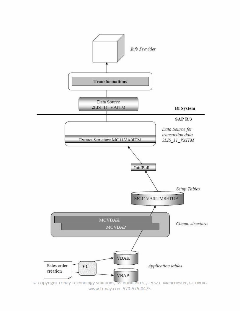
2.4 Data Extraction Logistics
New technique to extract logistics information and consists of a series of a standard extract structures (that is, from a more BW perspective, standard datasources), delivered in the business content. Data Extraction is the process of loading data from OLTP to OLAP (BW/BI).
2.4.1 Data extraction Illustration
Data can be extracted in two modes
1. Full Load – Entire data which available at source is loaded to BW/BI2. Delta load - Only the new/changed/deleted data is loaded.
2.4.1.1 Full Load:
Document posting means creating a transaction, writing into the application/transaction tables. So whenever sales order is created ( document posted), it transaction is written into the database tables/ application tables/transaction tables (Ex. EKPO, EKKO, VBAK, VBAP).Whenever the user are doing a full load, setup tables are used.
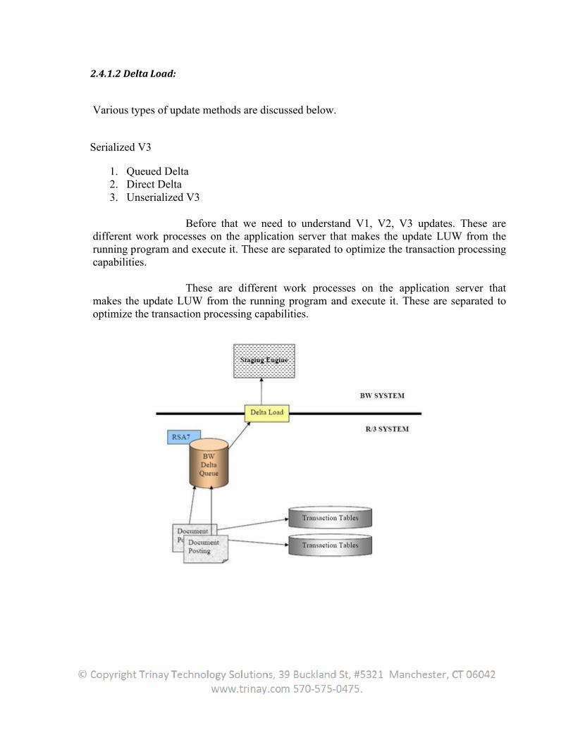
2.4.1.2 Delta Load:
Various types of update methods are discussed below.
Serialized V3
1. Queued Delta2. Direct Delta3. Unserialized V3
Before that we need to understand V1, V2, V3 updates. These are different work processes on the application server that makes the update LUW from the running program and execute it. These are separated to optimize the transaction processing capabilities.
These are different work processes on the application server that makes the update LUW from the running program and execute it. These are separated to optimize the transaction processing capabilities.
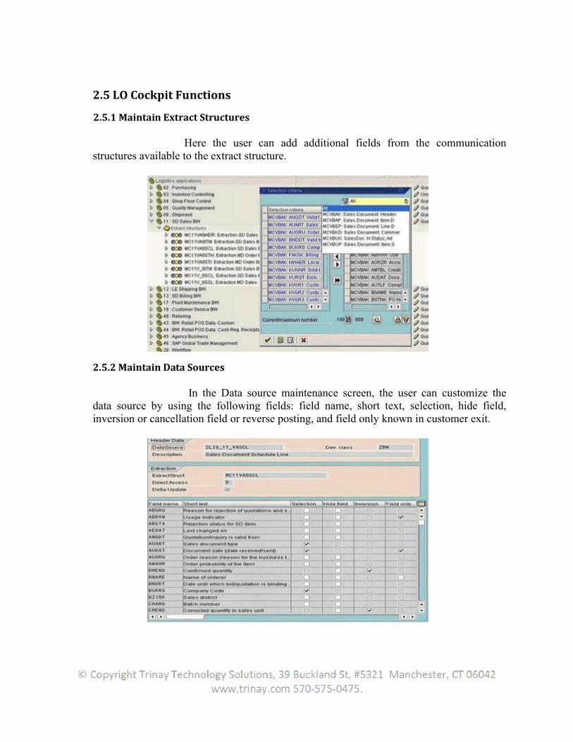
2.5 LO Cockpit Functions
2.5.1 Maintain Extract Structures
Here the user can add additional fields from the communication structures available to the extract structure.
2.5.2 Maintain Data Sources
In the Data source maintenance screen, the user can customize the data source by using the following fields: field name, short text, selection, hide field, inversion or cancellation field or reverse posting, and field only known in customer exit.
2.5.3 Activating update
By Setting as active, data is written into extract structures both online as well as during completion of setup tables or restructure table or LO initialization tables. Depending on the update mode a job has to be scheduled with which the updated data is transferred in the background into the central delta management (Delta Queue).
2.5.4 Controlling update
These talks about the delta update mode the user are using and how do the user control the data load based on the volume of data. LO Cockpit supports 4 types of update modes (delta modes, which we have already discussed): Serialized V3 update, Direct Delta, Queued Delta, Unserialized V3 update.
2.5.5 Setup Tables
Access to application tables are not permitted, hence setup tables are there to collect the required data from the application tables. When a load fails, the user can re-run the load to pull the data from setup tables. Data will be there in setup tables. Setup tables are used to Initialize delta loads and for full load. Its part of LO Extraction scenario. With this option, the user avoid pulling from R/3 directly as we need to bring field values from multiple tables. The user can see the data in the setup tables. Setup table name wiil be extract structure name followed by SETUP. Set up table names starts with 'MC' followed by application component '01'/'02' etc and then last digits of the datasource name and then followed by SETUP Also we can say the communication structure (R/3 side, the user can check it in LBWE also) name followed by 'setup'.
The setup tables are the base tables for the Datasource used for Full upload. So if the user are going for only full upload full update is possible in LO extractors. Full update is possible in LO extractors. In the full update whatever data is present in the setup tables(from the last done in it) is sent to BW.But setup tables do not receive the delta data from the deltas done after the init.So if users full update should get ALL data from the source system will need to delete and re-fill setup tables.
2.5.6 Serialized V3
Take an example of the same PO item changing many times in quick succession. V1 (with enqueue mechanism) ensures that the OLTP tables are updated consistently. Update table gets these update records which may or may not end up in correct sequence (as there is no locking) when it reaches BW. 'Serialized V3' was to ensure this correct sequence of update records going from update tables to delta queue (and then to BW).Since update table records have the timestamp, when the V3 job runs, it can sequence these records correctly and thus achieve 'serialization'.
2.5.7 Queued Delta (the third update method)
With queued delta update mode, the extraction data (for the relevant application) is written in an extraction queue (instead of in the update data as in V3) and can be transferred to the BW delta queues by an update collective run, as previously executed during the V3 update. After activating this method, up to 10000 document delta/changes to one LUW are cumulated per datasource in the BW delta queues.If the user use this method, it will be necessary to schedule a job to regularly transfer the data to the delta queues As always, the simplest way to perform scheduling is via the "Job control" function in LBWE.SAP recommends to schedule this job hourly during normal operation after successful delta initialization, but there is no fixed rule: it depends from peculiarity of every specific situation (business volume, reporting needs and so on).
2.5.8 Direct Delta ( 2nd delta update method in our list)
With this update mode, Each document posting is directly transferred into the BW delta queue Each document posting with delta extraction leads to exactly one LUW in the respective BW delta queues Just to remember that ‘LUW’ stands for Logical Unit of Work and it can be considered as an inseparable sequence of database operations that ends with a database commit (or a roll-back if an error occurs).
2.5.9 Unserialized V3: (The last one)
With this update mode, that we can consider as the serializer’s brother, the extraction data continues to be written to the update tables using a V3 update module and then is read and processed by a collective update run (through LBWE).But, as the name of this method suggests, the V3 unserialized delta disowns the main characteristic of his brother: data is read in the update collective run without taking the sequence into account and then transferred to the BW delta queues.Issues:Only suitable for data target design for which correct sequence of changes is not important e.g. Material Movements V2 update has to be successful.
2.6 LO Data Sources Data Flow in R/3 :
DataSources reside in the source system so If I need to customize DataSource, I need to go to source system, one can directly login to Source System ( R/3 in our case) or From BW also can remotely login to Source System.
1. Logon to BW
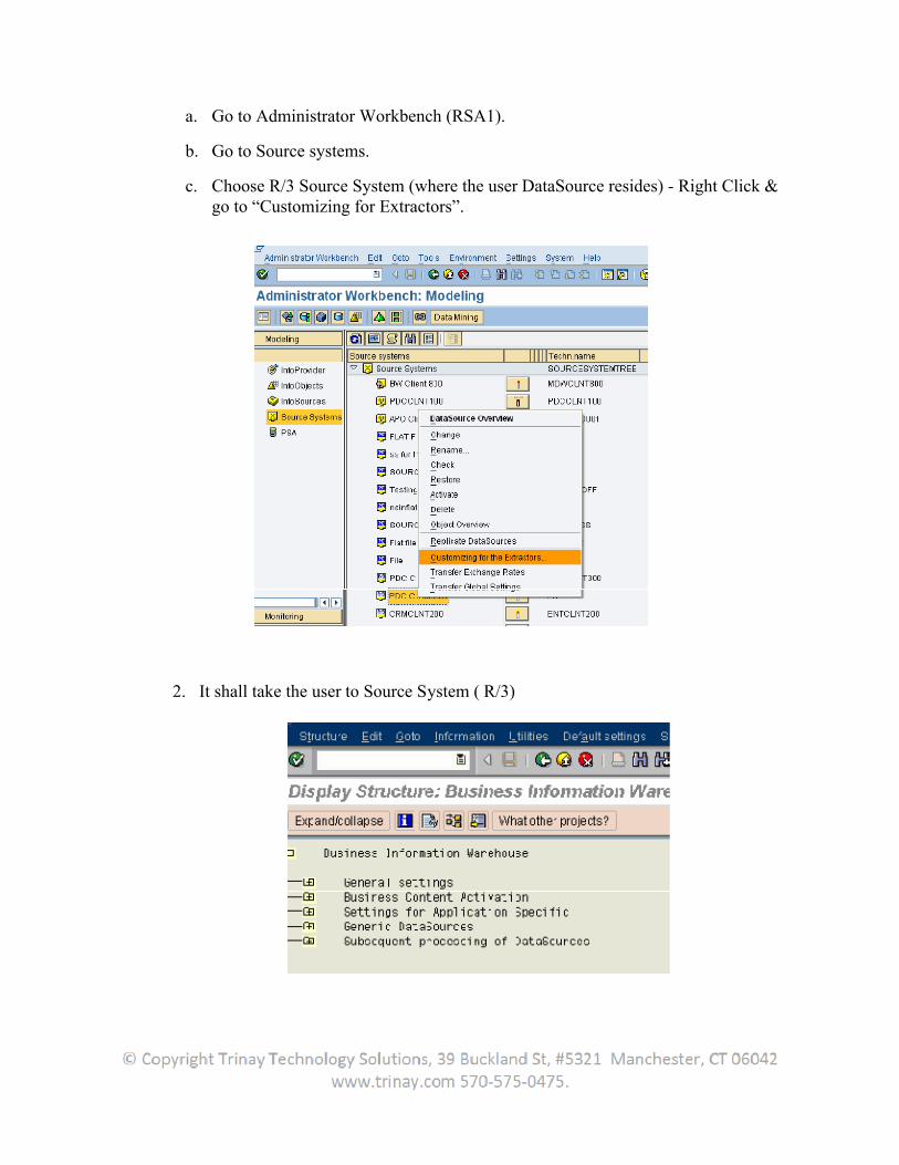
a. Go to Administrator Workbench (RSA1).
b. Go to Source systems.
c. Choose R/3 Source System (where the user DataSource resides) - Right Click & go to “Customizing for Extractors”.
2. It shall take the user to Source System ( R/3)

3. Choose “Edit DataSources and Application Component Hierarchy”
4. Go to “0CUSTOMER_ATTR” Customer Number DataSource ( or whatever DataSource the user decide to customize)
5. Click on DataSource 6. Scroll down to reach the appended structure
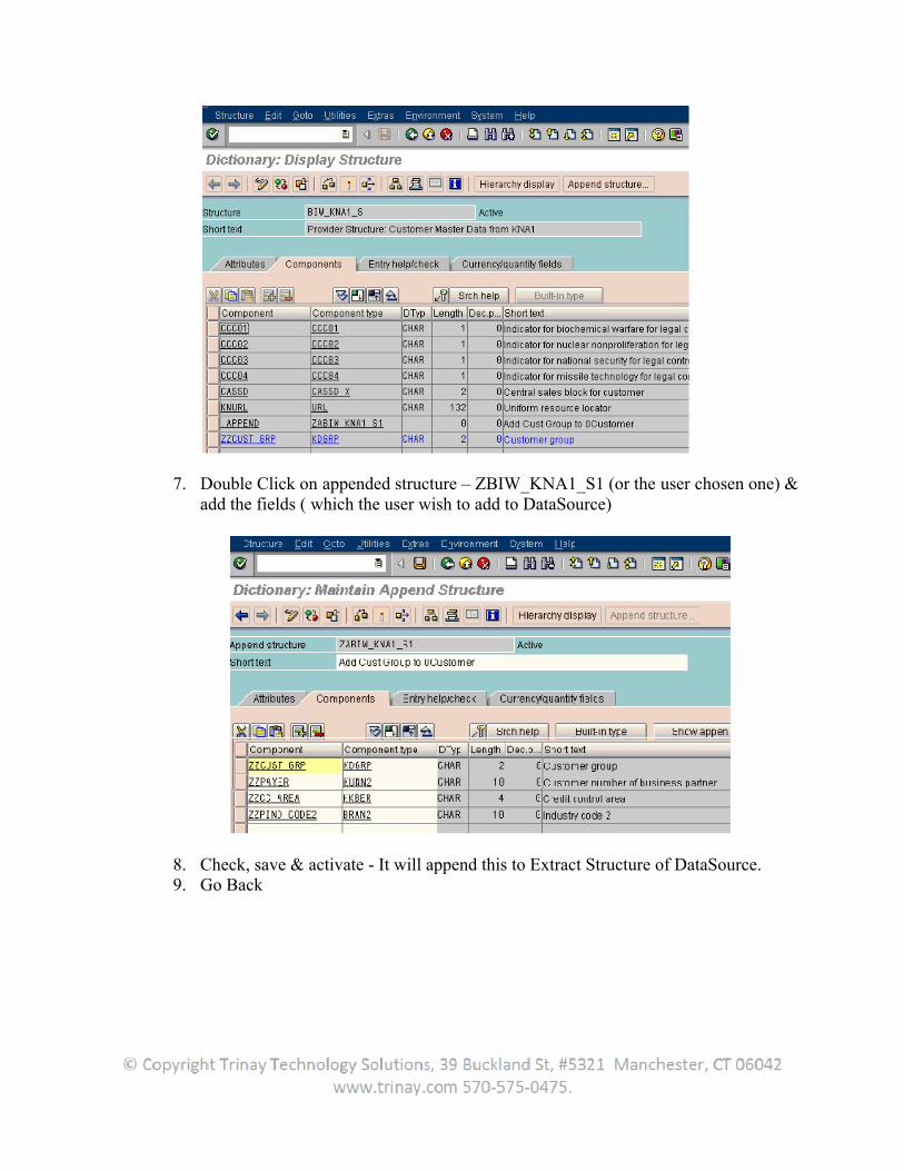
7. Double Click on appended structure – ZBIW_KNA1_S1 (or the user chosen one) & add the fields ( which the user wish to add to DataSource)
8. Check, save & activate - It will append this to Extract Structure of DataSource. 9. Go Back
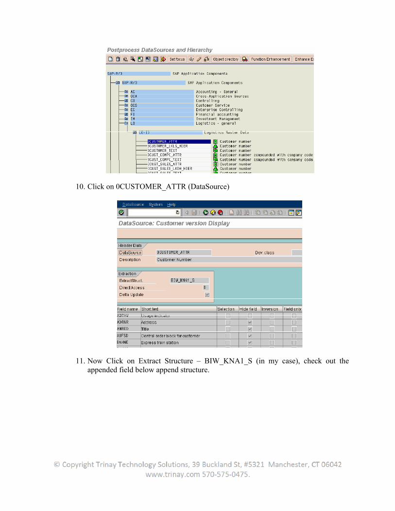
10. Click on 0CUSTOMER_ATTR (DataSource)
11. Now Click on Extract Structure – BIW_KNA1_S (in my case), check out the appended field below append structure.
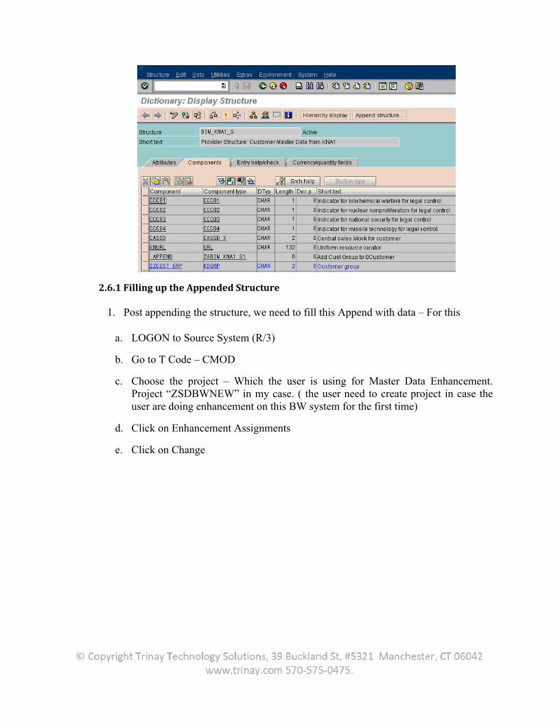
2.6.1 Filling up the Appended Structure
1. Post appending the structure, we need to fill this Append with data – For this
a. LOGON to Source System (R/3)
b. Go to T Code – CMOD
c. Choose the project – Which the user is using for Master Data Enhancement. Project “ZSDBWNEW” in my case. ( the user need to create project in case the user are doing enhancement on this BW system for the first time)
d. Click on Enhancement Assignments
e. Click on Change
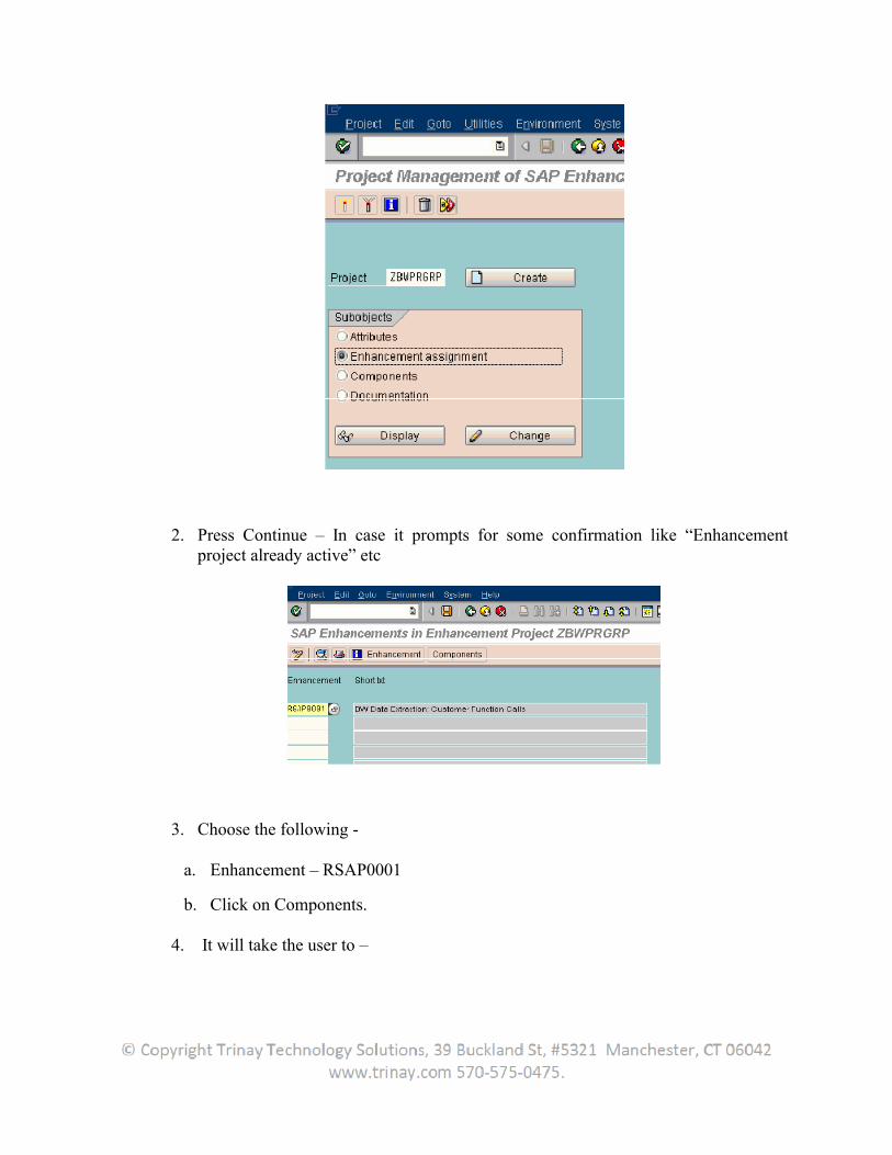
2. Press Continue – In case it prompts for some confirmation like “Enhancement project already active” etc
3. Choose the following -
a. Enhancement – RSAP0001
b. Click on Components.
4. It will take the user to –
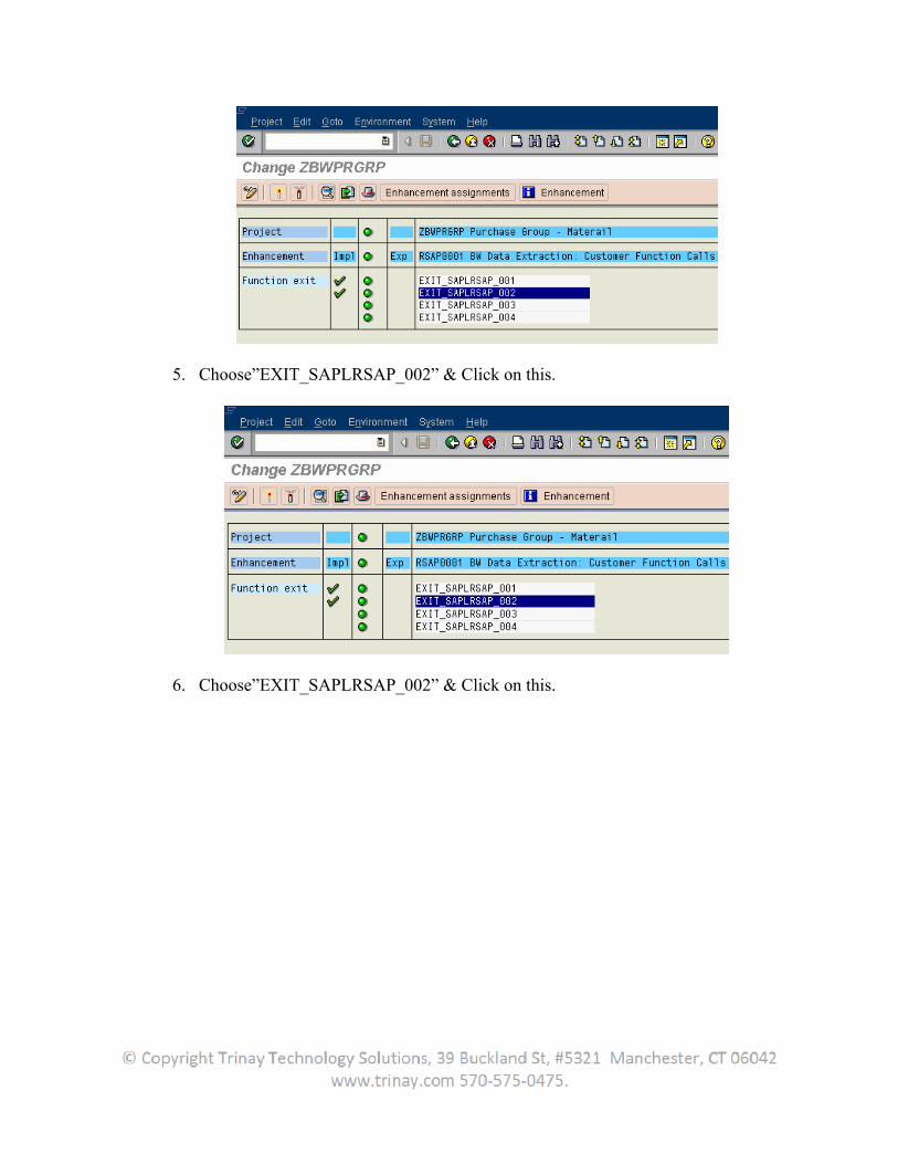
5. Choose”EXIT_SAPLRSAP_002” & Click on this.
6. Choose”EXIT_SAPLRSAP_002” & Click on this.
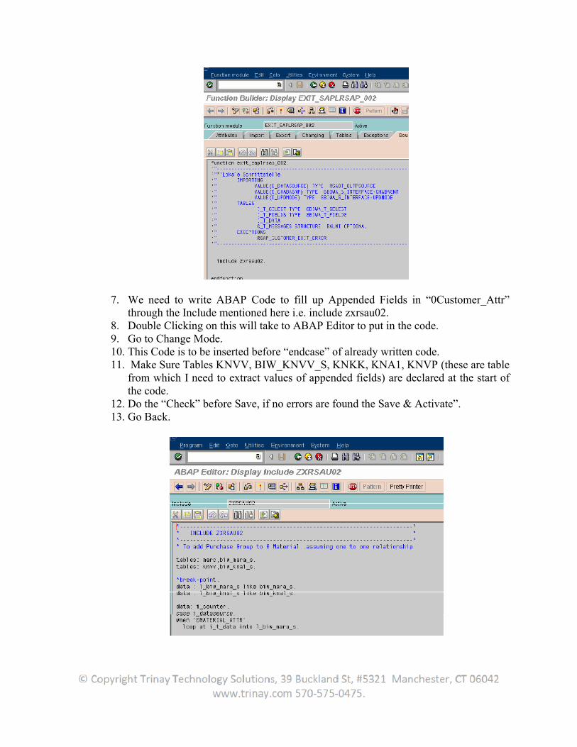
7. We need to write ABAP Code to fill up Appended Fields in “0Customer_Attr” through the Include mentioned here i.e. include zxrsau02.
8. Double Clicking on this will take to ABAP Editor to put in the code. 9. Go to Change Mode. 10. This Code is to be inserted before “endcase” of already written code. 11. Make Sure Tables KNVV, BIW_KNVV_S, KNKK, KNA1, KNVP (these are table
from which I need to extract values of appended fields) are declared at the start of the code.
12. Do the “Check” before Save, if no errors are found the Save & Activate”. 13. Go Back.
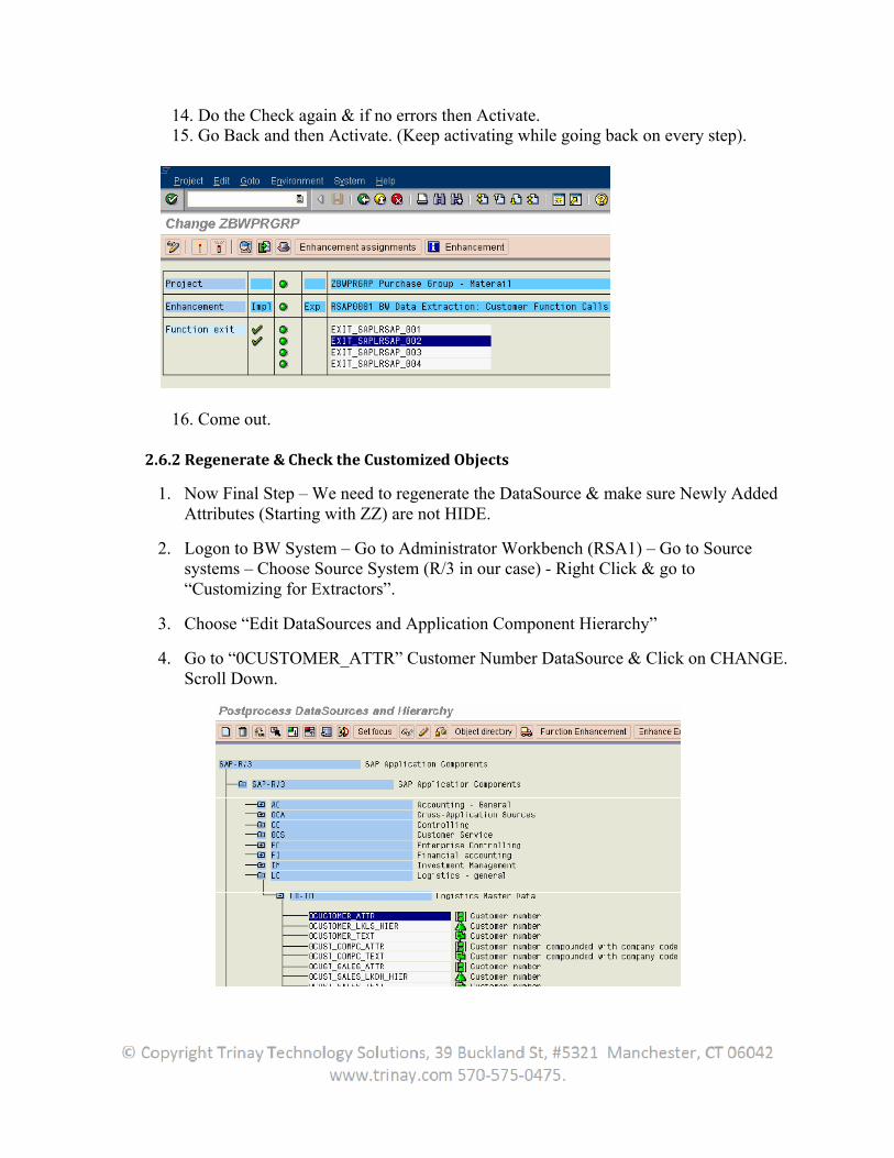
14. Do the Check again & if no errors then Activate. 15. Go Back and then Activate. (Keep activating while going back on every step).
16. Come out.
2.6.2 Regenerate & Check the Customized Objects
1. Now Final Step – We need to regenerate the DataSource & make sure Newly Added Attributes (Starting with ZZ) are not HIDE.
2. Logon to BW System – Go to Administrator Workbench (RSA1) – Go to Source systems – Choose Source System (R/3 in our case) - Right Click & go to “Customizing for Extractors”.
3. Choose “Edit DataSources and Application Component Hierarchy”
4. Go to “0CUSTOMER_ATTR” Customer Number DataSource & Click on CHANGE. Scroll Down.
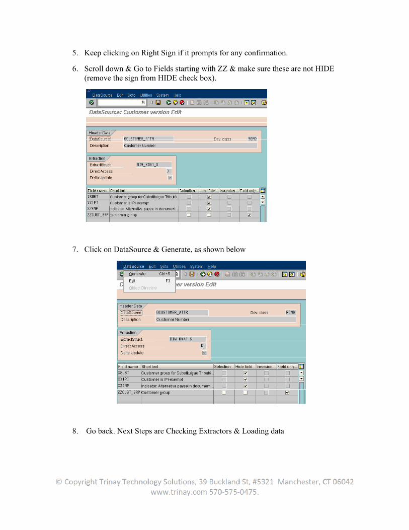
5. Keep clicking on Right Sign if it prompts for any confirmation.
6. Scroll down & Go to Fields starting with ZZ & make sure these are not HIDE (remove the sign from HIDE check box).
7. Click on DataSource & Generate, as shown below
8. Go back. Next Steps are Checking Extractors & Loading data
2.7 Structure of Delta Method for LO Cockpit Data Sources
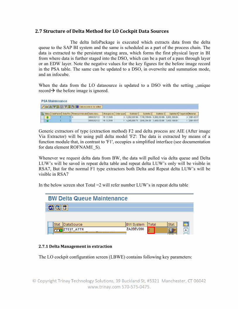
The delta InfoPackage is executed which extracts data from the delta queue to the SAP BI system and the same is scheduled as a part of the process chain. The data is extracted to the persistent staging area, which forms the first physical layer in BI from where data is further staged into the DSO, which can be a part of a pass through layer or an EDW layer. Note the negative values for the key figures for the before image recordin the PSA table. The same can be updated to a DSO, in overwrite and summation mode, and an infocube.
When the data from the LO datasource is updated to a DSO with the setting „uniquerecord the before image is ignored.
Generic extractors of type (extraction method) F2 and delta process are AIE (After image Via Extractor) will be using pull delta model 'F2': The data is extracted by means of a function module that, in contrast to 'F1', occupies a simplified interface (see documentation for data element ROFNAME_S).
Whenever we request delta data from BW, the data will pulled via delta queue and Delta LUW’s will be saved in repeat delta table and repeat delta LUW’s only will be visible in RSA7, But for the normal F1 type extractors both Delta and Repeat delta LUW’s will be visible in RSA7
In the below screen shot Total =2 will refer number LUW’s in repeat delta table
2.7.1 Delta Management in extraction
The LO cockpit configuration screen (LBWE) contains following key parameters:
Maintenance of extract structures Maintaining InfoSources Activating the update Job control Update Mode
a. Serialized V3 Update The document data is collected in the order it was created and transferred into the BW as a batch job.
b. Direct Delta The extraction data is transferred directly from document postings into the BW delta queue. The transfer sequence is the same as the order in which the data was created.
c. Queued Delta The extraction data from document postings is collected in an extraction queue, from which a periodic collective run is used to
transfer the data into the BW delta queue. The transfer sequence is the
same as the order in which the data was created. d. Unserialized V3 Update This method is opposite to the Serialized V3 Update. The BW delta queue does not have to be the same as the order in which it was posted.
2.7.2 Step-by-Step Maintenance
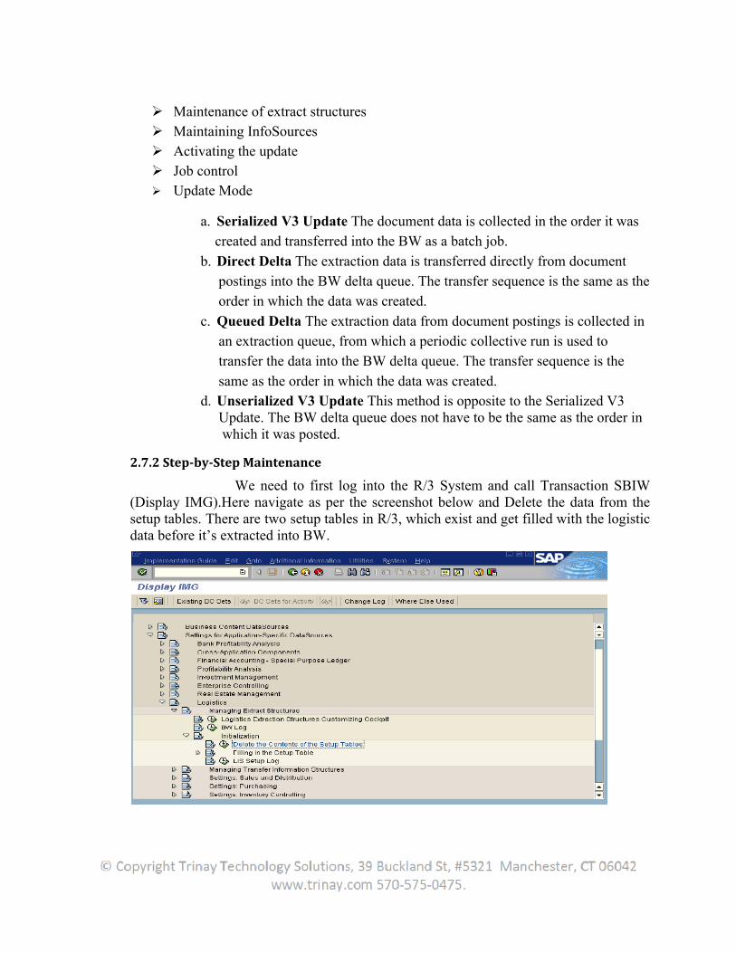
We need to first log into the R/3 System and call Transaction SBIW (Display IMG).Here navigate as per the screenshot below and Delete the data from the setup tables. There are two setup tables in R/3, which exist and get filled with the logistic data before it’s extracted into BW.
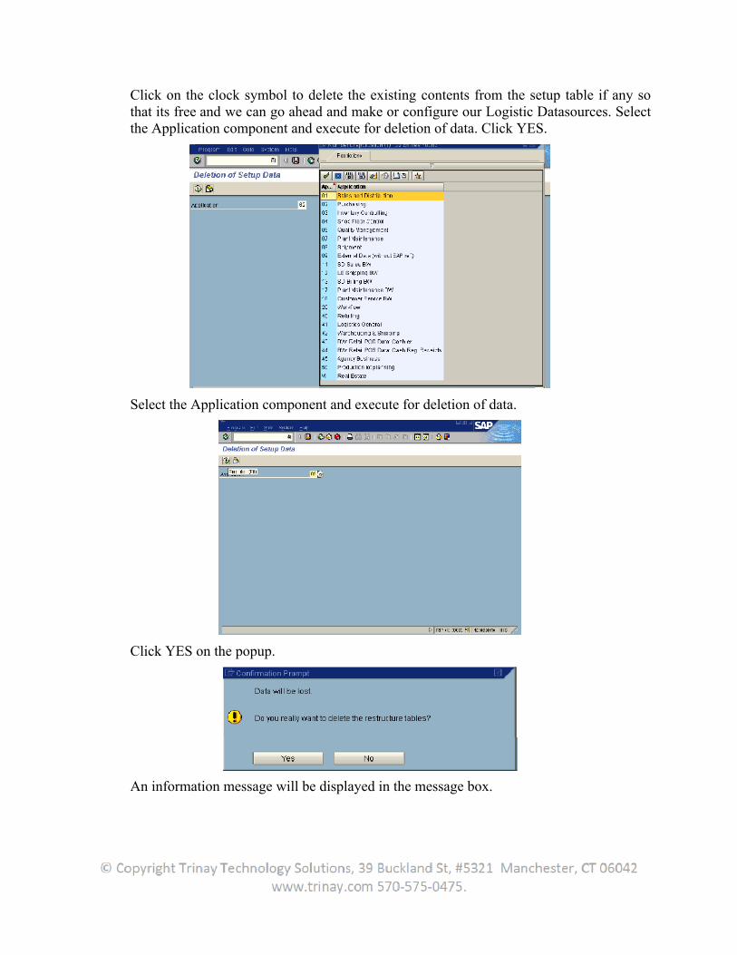
Click on the clock symbol to delete the existing contents from the setup table if any so that its free and we can go ahead and make or configure our Logistic Datasources. Select the Application component and execute for deletion of data. Click YES.
Select the Application component and execute for deletion of data.
Click YES on the popup.
An information message will be displayed in the message box.
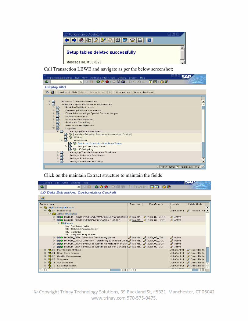
Call Transaction LBWE and navigate as per the below screenshot:
Click on the maintain Extract structure to maintain the fields
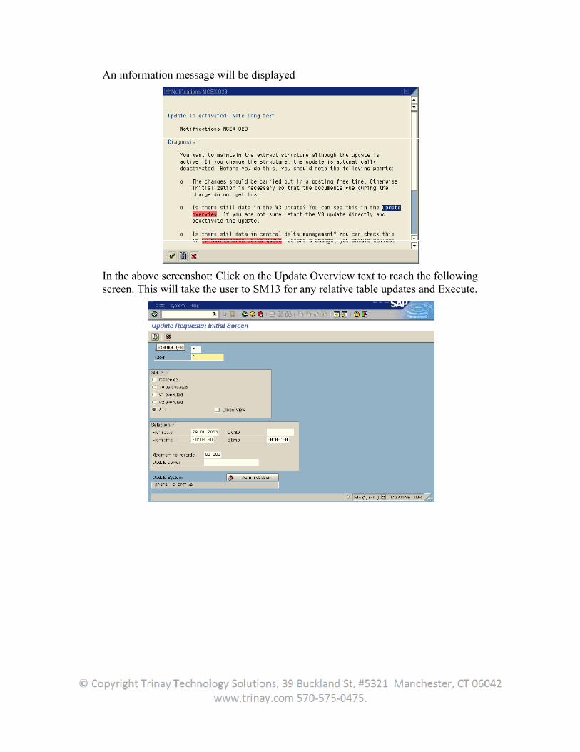
An information message will be displayed
In the above screenshot: Click on the Update Overview text to reach the following screen. This will take the user to SM13 for any relative table updates and Execute.
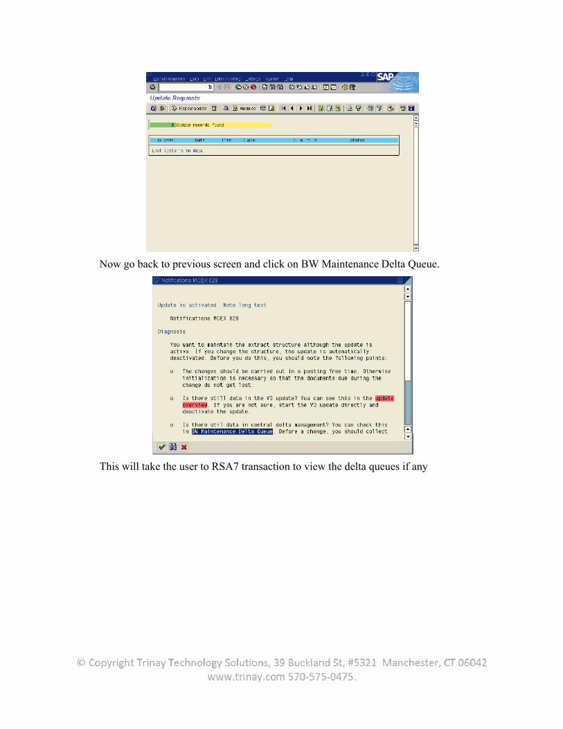
Now go back to previous screen and click on BW Maintenance Delta Queue.
This will take the user to RSA7 transaction to view the delta queues if any
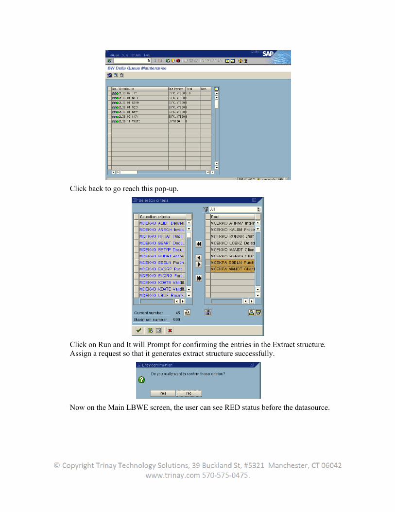
Click back to go reach this pop-up.
Click on Run and It will Prompt for confirming the entries in the Extract structure. Assign a request so that it generates extract structure successfully.
Now on the Main LBWE screen, the user can see RED status before the datasource.
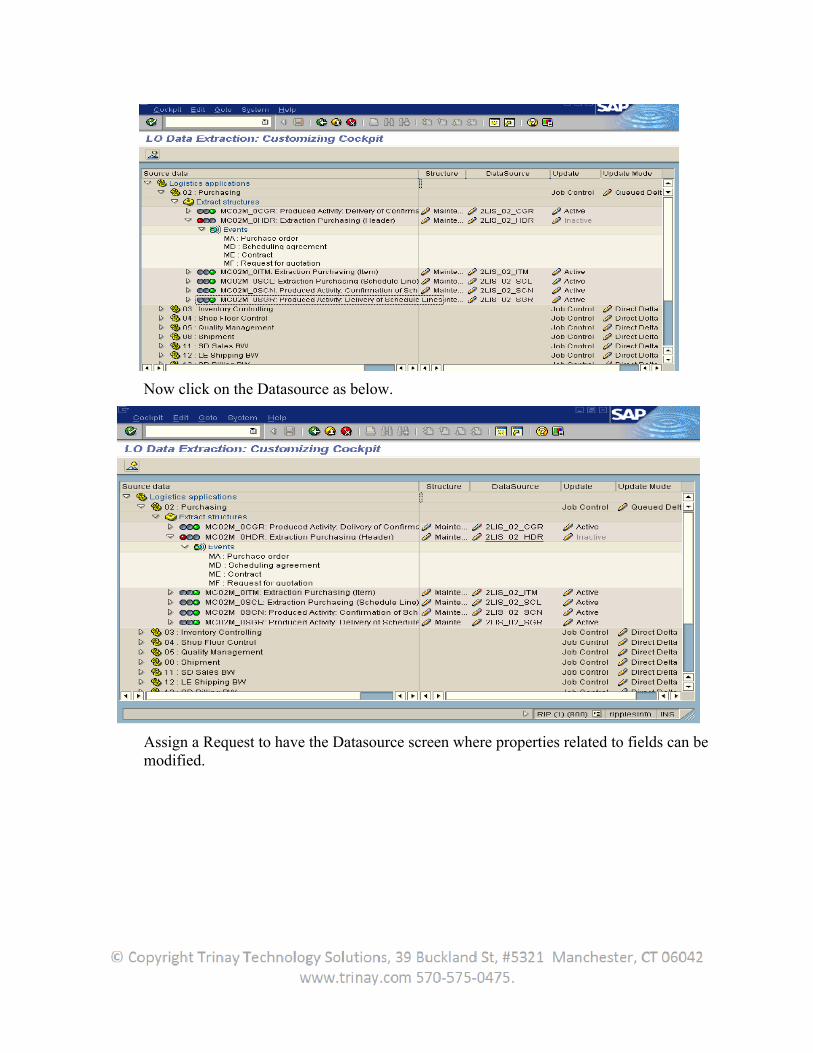
Now click on the Datasource as below.
Assign a Request to have the Datasource screen where properties related to fields can be modified.
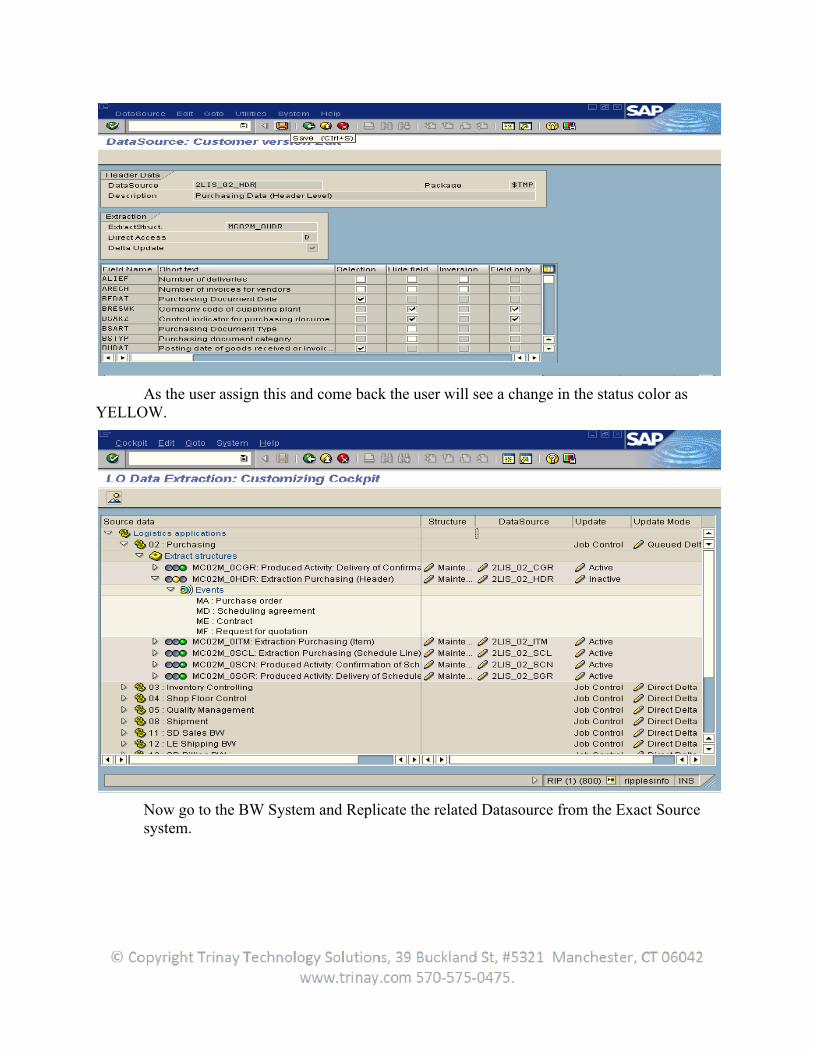
As the user assign this and come back the user will see a change in the status color as YELLOW.
Now go to the BW System and Replicate the related Datasource from the Exact Source system.
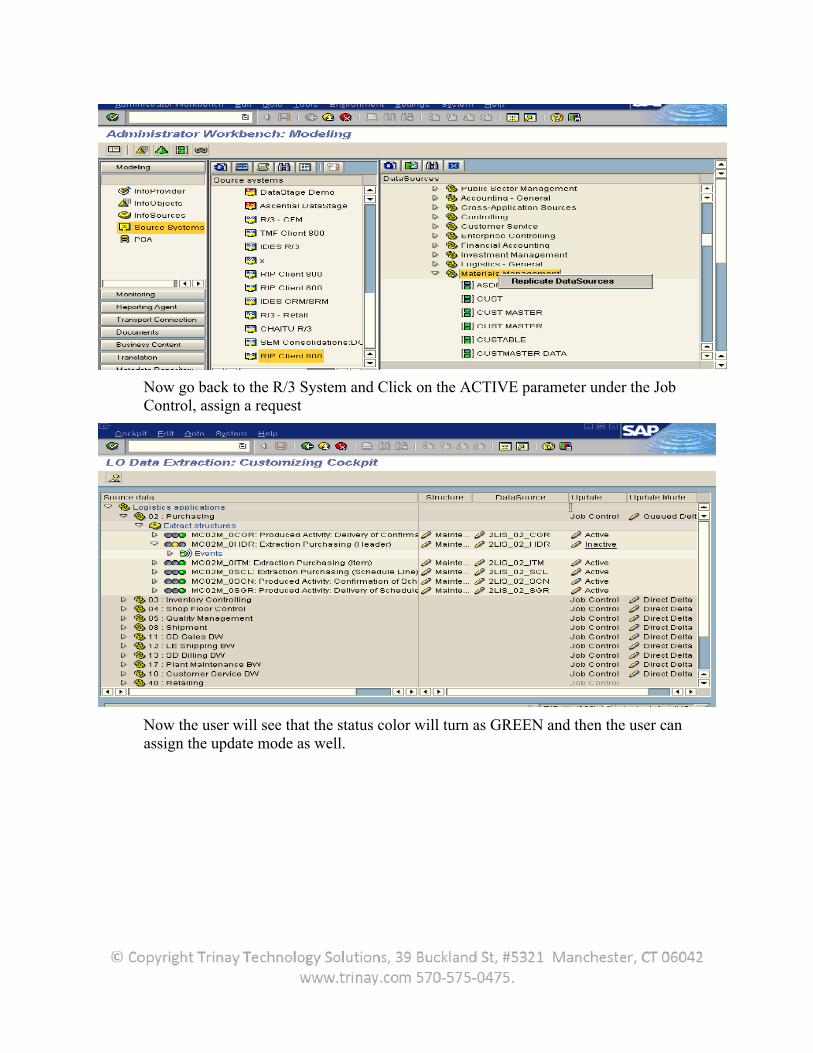
Now go back to the R/3 System and Click on the ACTIVE parameter under the Job Control, assign a request
Now the user will see that the status color will turn as GREEN and then the user can assign the update mode as well.
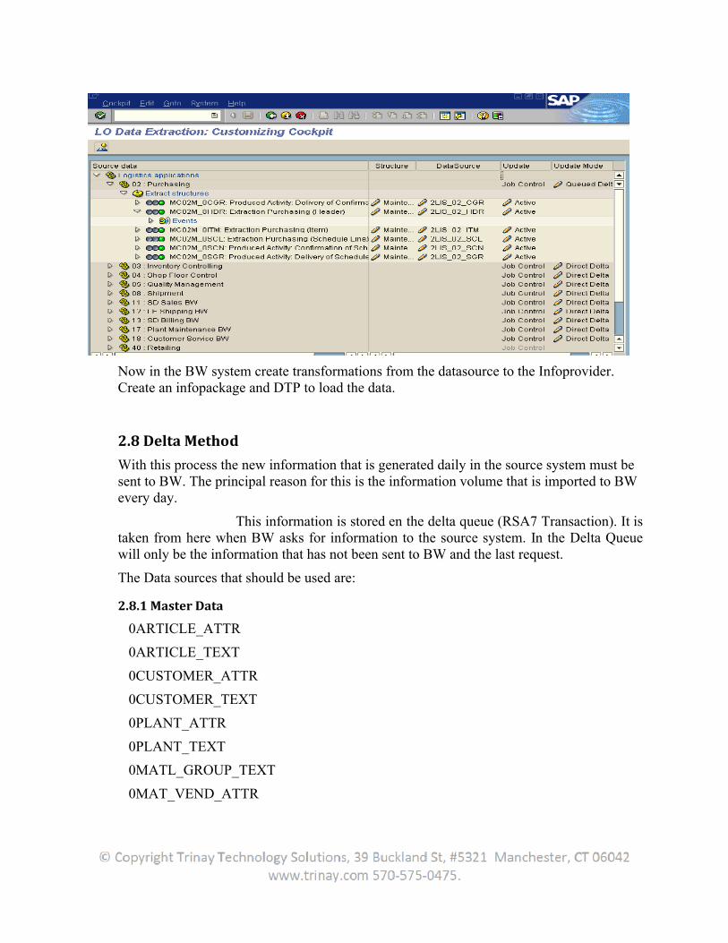
Now in the BW system create transformations from the datasource to the Infoprovider. Create an infopackage and DTP to load the data.
2.8 Delta Method
With this process the new information that is generated daily in the source system must be sent to BW. The principal reason for this is the information volume that is imported to BW every day.
This information is stored en the delta queue (RSA7 Transaction). It is taken from here when BW asks for information to the source system. In the Delta Queue will only be the information that has not been sent to BW and the last request.
The Data sources that should be used are:
2.8.1 Master Data
0ARTICLE_ATTR
0ARTICLE_TEXT
0CUSTOMER_ATTR
0CUSTOMER_TEXT
0PLANT_ATTR
0PLANT_TEXT
0MATL_GROUP_TEXT
0MAT_VEND_ATTR
0VENDOR_ATTR
0VENDOR_TEXT
0SALESORG_ATTR
0SALESORG_TEXT
0SALES_DIST_TEXT
0SALES_GRP_TEXT
0SALES_OFF_TEXT
0SALESORG_ATTR
0SALESORG_TEXT
0SALES_DIST_TEXT
0SALES_GRP_TEXT
0SALES_OFF_TEXT
2.8.2 TRANSACTIONAL DATA
2LIS_02_SCL
2LIS_03_BF
2LIS_03_BX
2LIS_03_UM
2LIS_13_VDITM
2LIS_40_REVAL
In the screen Installation of Data Source from Business Content, the user must mark the data source that the user wants to activate and select Activate Data Source.
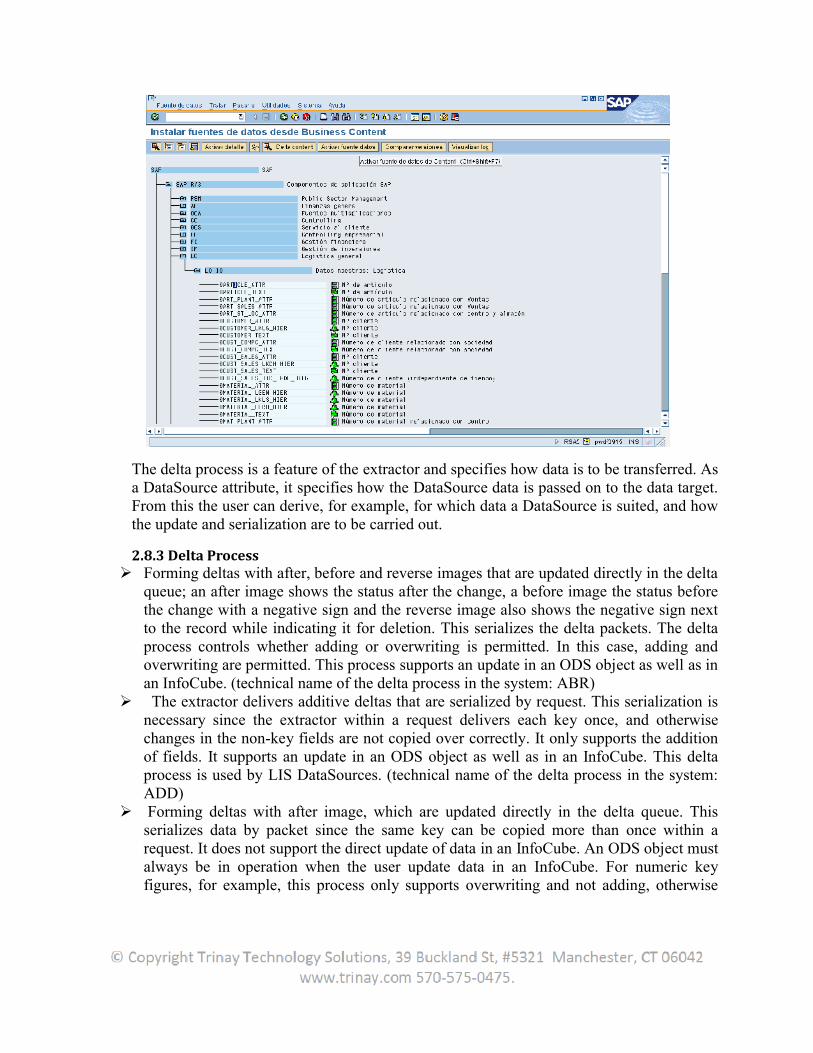
The delta process is a feature of the extractor and specifies how data is to be transferred. As a DataSource attribute, it specifies how the DataSource data is passed on to the data target. From this the user can derive, for example, for which data a DataSource is suited, and how the update and serialization are to be carried out.
2.8.3 Delta Process Forming deltas with after, before and reverse images that are updated directly in the delta
queue; an after image shows the status after the change, a before image the status before the change with a negative sign and the reverse image also shows the negative sign next to the record while indicating it for deletion. This serializes the delta packets. The delta process controls whether adding or overwriting is permitted. In this case, adding and overwriting are permitted. This process supports an update in an ODS object as well as in an InfoCube. (technical name of the delta process in the system: ABR)
The extractor delivers additive deltas that are serialized by request. This serialization is necessary since the extractor within a request delivers each key once, and otherwise changes in the non-key fields are not copied over correctly. It only supports the addition of fields. It supports an update in an ODS object as well as in an InfoCube. This delta process is used by LIS DataSources. (technical name of the delta process in the system: ADD)
Forming deltas with after image, which are updated directly in the delta queue. This serializes data by packet since the same key can be copied more than once within a request. It does not support the direct update of data in an InfoCube. An ODS object must always be in operation when the user update data in an InfoCube. For numeric key figures, for example, this process only supports overwriting and not adding, otherwise
incorrect results would come about. It is used in FI-AP/AR for transferring line items, while the variation of the process, where extractor can also send records with the deletion flag, is used in capacity in BBP. (technical name of the delta process in the system: AIM/AIMD)
2.9 Delta Method Properties
2.9.1 Delta Initialization
In contrast with other business content and generic data sources, the LO datasources use the concept of set up tables to carry out the initial data extraction process. The data extractors for HR, FI etc. extract data by directly accessing the application tables, but in case of LO extractors they do not access the application tables directly. The presence of restructuring/set up tables prevents the BI extractors directly access the frequently updated large logistics application tables and are only used for initialization of data to BI. For loading data first time into the BI system, the set up tables have to be filled. The restructuring/set up tables are cluster tables that hold the respective application data, and the BI system extracts the data as a onetime activity for the initial data load, and the data can be deleted from the set up tables after successful data extraction into BI to avoid redundant storage.
The setup tables in SAP have the naming convention, <Extraction structure>SETUP and the compressed data from application tables stored here can be viewed through SE11. Thus the datasource 2LIS_11_VAITM having extract structure MC11VA0ITM has the set up table MC11VA0ITMSETUP. A job is executed to fill the set up tables, and the init InfoPackage extracts the initial data into BI.
2.9. 2 Delta Extraction
Once the initialization of the logistics transaction data datasource is successfully carried out, all subsequent new and changed records are extracted to the BI system using the delta mechanism supported by the datasource. The LO datasources support ABR delta mechanism which is both DSO and InfoCube compatible. The ABRdelta creates delta with after, before and reverse images that are updated directly to the delta queue, which gets automatically generated after successful delta initialization.
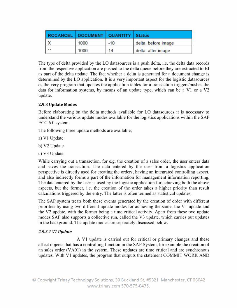
The after image provides status after change, a before image gives status before the change with a minus sign and a reverse image sends the record with a minus sign for the deleted records. The serialization plays an important role if the delta records has to be updated into a DSO in overwrite mode. For e.g. in the sales document 1000, if the quantity of ordered material is changed to 14 from 10, then the data gets extracted as shown in the table,
The type of delta provided by the LO datasources is a push delta, i.e. the delta data records from the respective application are pushed to the delta queue before they are extracted to BI as part of the delta update. The fact whether a delta is generated for a document change is determined by the LO application. It is a very important aspect for the logistic datasources as the very program that updates the application tables for a transaction triggers/pushes the data for information systems, by means of an update type, which can be a V1 or a V2 update.
2.9.3 Update Modes
Before elaborating on the delta methods available for LO datasources it is necessary to understand the various update modes available for the logistics applications within the SAP ECC 6.0 system.
The following three update methods are available;
a) V1 Update
b) V2 Update
c) V3 Update
While carrying out a transaction, for e.g. the creation of a sales order, the user enters data and saves the transaction. The data entered by the user from a logistics application perspective is directly used for creating the orders, having an integrated controlling aspect, and also indirectly forms a part of the information for management information reporting. The data entered by the user is used by the logistic application for achieving both the above aspects, but the former, i.e. the creation of the order takes a higher priority than result calculations triggered by the entry. The latter is often termed as statistical updates.
The SAP system treats both these events generated by the creation of order with different priorities by using two different update modes for achieving the same, the V1 update and the V2 update, with the former being a time critical activity. Apart from these two update modes SAP also supports a collective run, called the V3 update, which carries out updates in the background. The update modes are separately discussed below.
2.9.3.1 V1 Update
A V1 update is carried out for critical or primary changes and these affect objects that has a controlling function in the SAP System, for example the creation of an sales order (VA01) in the system. These updates are time critical and are synchronous updates. With V1 updates, the program that outputs the statement COMMIT WORK AND
WAIT which waits until the update work process outputs the status of the update. The program then responds to errors separately.
The V1 updates are processed sequentially in a single update work process and they belong to the same database LUW. These updates are executed under the SAP locks of the transaction that creates the update there by ensuring consistency of data, preventing simultaneous updates. The most important aspect is that the V1 synchronous updates can never be processed a second time. During the creation of an order the V1 update writes data into the application tables and the order gets processed. The V1 updates are carried out as a priority in contrast to V2 updates, though the V2 updates are usually also processed straight away.
2.9.3.2 V2 Update
A V2 update, in contrast with V1 is executed for less critical secondary changes and are pure statistical updates resulting from the transaction. They are carried out in a separate LUW and not under the locks of the transaction that creates them. They are often executed in the work process specified for V2 updates. If this is not the case, the V2 components are processed by a V1 update process but the V1 updates must be processed before the V2 update. They are asynchronous in nature.
2.9.3.3 V3 Update
Apart from the above mentioned V1 and V2 updates, the SAP system also has another update method called the V3 update which consists of collective run function modules. Compared to the V1 and V2 updates, the V3 update is a batch asynchronous update, which is carried out when a report (RSM13005) starts the update (in background mode). The V3 update does not happen automatically unlike the V1 and V2 updates.
All function module calls are then collected, aggregated and updated together and are handled in the same way as V2 update modules. If one of the function modules increments a statistical entry by one, this is called up 10 times during the course of the transaction. Implementing the same as a V2 update runs 10 times after the V1 for the same has been completed; i.e. the database is updated 10 times. But when executed as a V3 update, the update can be executed at any time in one single operation with the same being carried out in one database operation at a later point in time. This largely reduces the load on the system.
2.10 Delta Queue Functions
The LO datasource implements its delta functionality using the above update methods either individually or as a combination of them. SAP provides different mechanisms for pushing the data into the delta queue and is called update modes.
The different update modes available with LO datasources are;a. Direct Delta
b. Queued Deltac. Un-serialized V3 Delta
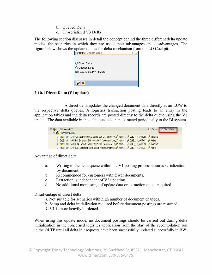
The following section discusses in detail the concept behind the three different delta update modes, the scenarios in which they are used, their advantages and disadvantages. The figure below shows the update modes for delta mechanism from the LO Cockpit.
2.10.1 Direct Delta (V1 update)
A direct delta updates the changed document data directly as an LUW to the respective delta queues. A logistics transaction posting leads to an entry in the application tables and the delta records are posted directly to the delta queue using the V1 update. The data available in the delta queue is then extracted periodically to the BI system.
Advantage of direct delta
a. Writing to the delta queue within the V1 posting process ensures serialization by document.b. Recommended for customers with fewer documents.c. Extraction is independent of V2 updating.d. No additional monitoring of update data or extraction queue required.
Disadvantage of direct deltaa. Not suitable for scenarios with high number of document changes.b. Setup and delta initialization required before document postings are resumed.
C.V1 is more heavily burdened.
When using this update mode, no document postings should be carried out during delta initialization in the concerned logistics application from the start of the recompilation run in the OLTP until all delta init requests have been successfully updated successfully in BW.
The data from documents posted is completely lost if documents are posted during the re-initialization process.
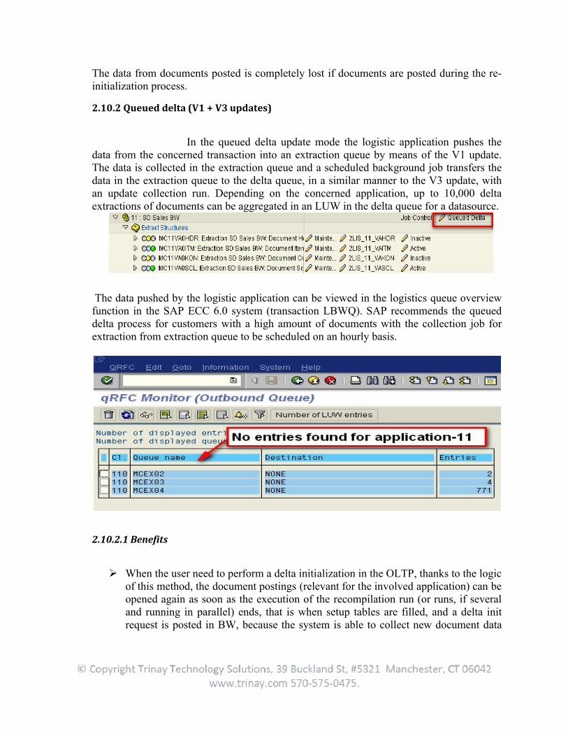
2.10.2 Queued delta (V1 + V3 updates)
In the queued delta update mode the logistic application pushes the data from the concerned transaction into an extraction queue by means of the V1 update. The data is collected in the extraction queue and a scheduled background job transfers the data in the extraction queue to the delta queue, in a similar manner to the V3 update, with an update collection run. Depending on the concerned application, up to 10,000 deltaextractions of documents can be aggregated in an LUW in the delta queue for a datasource.
The data pushed by the logistic application can be viewed in the logistics queue overview function in the SAP ECC 6.0 system (transaction LBWQ). SAP recommends the queued delta process for customers with a high amount of documents with the collection job for extraction from extraction queue to be scheduled on an hourly basis.
2.10.2.1 Benefits
When the user need to perform a delta initialization in the OLTP, thanks to the logic of this method, the document postings (relevant for the involved application) can be opened again as soon as the execution of the recompilation run (or runs, if several and running in parallel) ends, that is when setup tables are filled, and a delta init request is posted in BW, because the system is able to collect new document data
during the delta init uploading too (with a deeply felt recommendation: remember to avoid update collective run before all delta init requests have been successfully updated in the user BW!).
By writing in the extraction queue within the V1 update process (that is more burdened than by using V3), the serialization is ensured by using the enqueue concept, but collective run clearly performs better than the serialized V3 and especially slowing-down due to documents posted in multiple languages does not apply in this method.
On the contrary of direct delta, this process is especially recommended for customers with a high occurrence of documents (more than 10,000 document changes - creation, change or deletion - performed each day for the application in question.
Extraction is independent of V2 update.
In contrast to the V3 collective run an event handling is possible here, because a definite end for the collective run is identifiable: in fact, when the collective run for an application ends, an event (&MCEX_nn, where nn is the number of the application) is automatically triggered and, thus, it can be used to start a subsequent job.
2.10.2.2 Limits
V1 is more heavily burdened compared to V3.
Administrative overhead of extraction queue.
The job uses the report RMBWV311 for collection run and the function module will have the naming convention MCEX_UPDATE_<Application>, MCEX_UPDATE_11 for sales orders. In the initialization process, the collection of new document data during the delta initialization request can reduce the downtime on the restructuring run. The entire extraction process is independent of the V2 update process.
2.10.3 Un-serialized V3 Update (V1/V2 + V3 Updates)
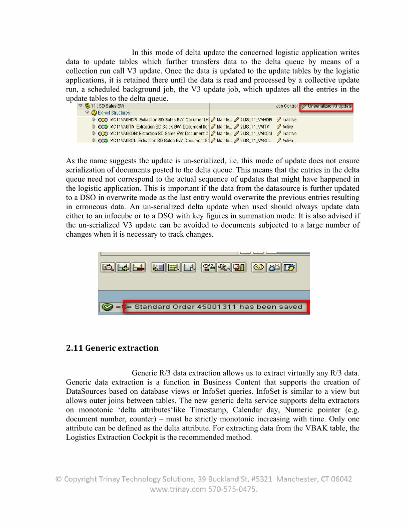
In this mode of delta update the concerned logistic application writes data to update tables which further transfers data to the delta queue by means of a collection run call V3 update. Once the data is updated to the update tables by the logistic applications, it is retained there until the data is read and processed by a collective update run, a scheduled background job, the V3 update job, which updates all the entries in theupdate tables to the delta queue.
As the name suggests the update is un-serialized, i.e. this mode of update does not ensure serialization of documents posted to the delta queue. This means that the entries in the delta queue need not correspond to the actual sequence of updates that might have happened in the logistic application. This is important if the data from the datasource is further updated to a DSO in overwrite mode as the last entry would overwrite the previous entries resulting in erroneous data. An un-serialized delta update when used should always update data either to an infocube or to a DSO with key figures in summation mode. It is also advised if the un-serialized V3 update can be avoided to documents subjected to a large number of changes when it is necessary to track changes.
2.11 Generic extraction
Generic R/3 data extraction allows us to extract virtually any R/3 data. Generic data extraction is a function in Business Content that supports the creation of DataSources based on database views or InfoSet queries. InfoSet is similar to a view but allows outer joins between tables. The new generic delta service supports delta extractors on monotonic ‘delta attributes‘like Timestamp, Calendar day, Numeric pointer (e.g. document number, counter) – must be strictly monotonic increasing with time. Only one attribute can be defined as the delta attribute. For extracting data from the VBAK table, the Logistics Extraction Cockpit is the recommended method.
2.11.1Create Generic extraction [Master data]
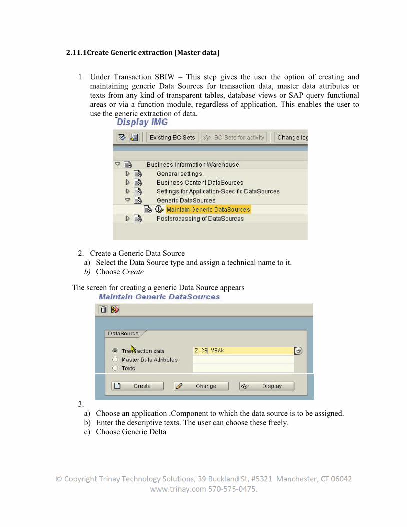
1. Under Transaction SBIW – This step gives the user the option of creating and maintaining generic Data Sources for transaction data, master data attributes or texts from any kind of transparent tables, database views or SAP query functional areas or via a function module, regardless of application. This enables the user to use the generic extraction of data.
2. Create a Generic Data Sourcea) Select the Data Source type and assign a technical name to it.b) Choose Create
The screen for creating a generic Data Source appears
3.a) Choose an application .Component to which the data source is to be assigned.b) Enter the descriptive texts. The user can choose these freely.c) Choose Generic Delta
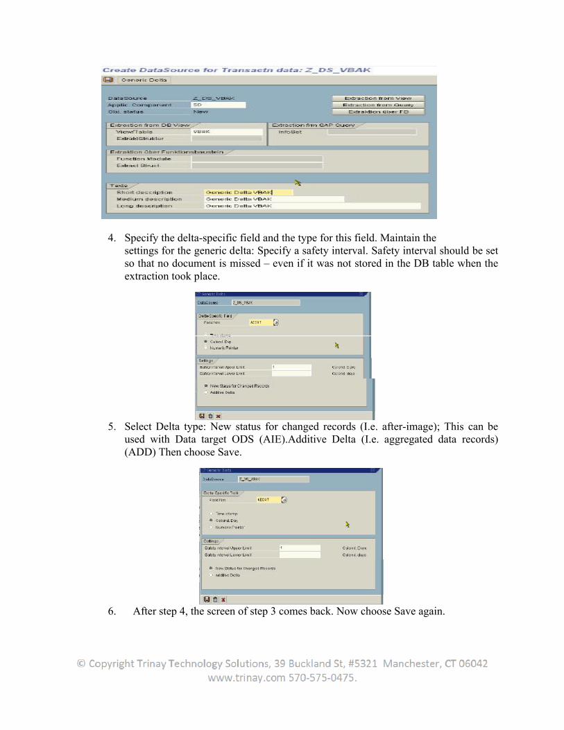
4. Specify the delta-specific field and the type for this field. Maintain thesettings for the generic delta: Specify a safety interval. Safety interval should be set so that no document is missed – even if it was not stored in the DB table when theextraction took place.
5. Select Delta type: New status for changed records (I.e. after-image); This can be used with Data target ODS (AIE).Additive Delta (I.e. aggregated data records) (ADD) Then choose Save.
6. After step 4, the screen of step 3 comes back. Now choose Save again.

This will generate the data source. After generating the data source, the user will see the Delta Update flag selected. In systems as of basis release 4.0B,the user can display the current value for the delta-relevant field in the delta queue.
7. Choose Save again
Delta Attributes can be monitored in delta queue (RSA7). Also note LUW count does not equal to the changes records in the source table. Most of the time it will be ZERO. Delta is enabled by data selection logic
LUW count can also have value 1.Whenever delta is extracted, the extracted data is stored in the delta queue tables to serve as a fallback, when an error occurs during
the update of the BW system. The user will see a '1' in this field (the extract counts as one LUW) and are even able to be displayed in a detail screen.
2.12 Generic Data Types
2.12.1 Master Data
In SAP BW, three different types of master data can be differentiatedin InfoObjects.
2.12.1.1. Texts Texts are used to describe a master record. In SAP Business Information Warehouse (SAP BW), up to three texts can be maintained for each master record. These texts can consist of the following: one short text, one medium text, and one long text. An example of a master data text is the name of the supplier that goes with the supplier number.
2.12.1.2. Attributes Master data attributes are fields that are used to provide a moredetailed description of master data elements. These attributes are used to display additional information so results can be better understood. An attribute table can be used by several InfoCubes. This ensures a higher level of transparency for the user and a more comprehensive consistency. An example of a master data attribute is the country of thesupplier that goes with the supplier number.
2.12.1.3. Hierarchies Hierarchies can be used in the analysis to describe alternative views ofthe data. A hierarchy consists of a quantity of nodes that have a parent child relationship with one another. The structures can be defined in a version-specific as well as a time-dependent manner. An example of this is the cost center hierarchy.
2.12.2 Functions
2.12.2.1 Time-dependent Attributes
If the characteristic has at least 1 time-dependent attribute, a time interval is specified for this attribute. As master data must exist between the period of 01.01.1000 and 12.31.1000 in the database, the gaps are filled automatically.
2.12.2.2 Time-dependent Texts
If the user creates time-dependent texts, the text for the key date is always displayed in the query.
2.12.2.3 Time-dependent Texts and Attributes
If the texts and the attributes are time-dependent, the time intervals do not have to agree.
2.12.2.4 Language-dependent Texts
In the Characteristic InfoObject Maintenance, the user can determine whether the texts are language-specific (for example, with product names: German Auto, English car), or not (for example, customer names). Only the texts in the selected language are displayed.
If they are language-dependent, the user have to upload all texts with a language indicator.
2.12.3 Transactional data
Transaction data includes origination data, monthly account data, competitive data, and macroeconomic data. It is regularly updated and loaded into the system. When loading transactional data, the system utilizes elements of the master data to process the transactions. Transaction data - Any business event in SAP R/3 leads to transaction data being generated. SAP R/3 handles transaction data at the document level or at the summary level. Document level transaction data is detailed data and consists of headers, line items, and schedule lines. Summary transactional data is used in SAP R/3 for mostly reporting purposes.
Generic extractors are of 3 types:
1. Based on table/view2. Based on Infoset Query3. Based on Function module
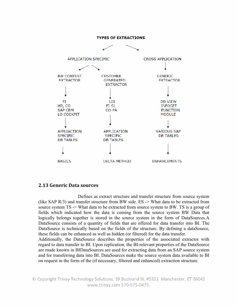
2.13 Generic Data sources
Defines as extract structure and transfer structure from source system (like SAP R/3) and transfer structure from BW side. ES -> What data to be extracted from source system TS -> What data to be extracted from source system to BW. TS is a group of fields which indicated how the data is coming from the source system BW Data that logically belongs together is stored in the source system in the form of DataSources.A DataSource consists of a quantity of fields that are offered for data transfer into BI. The DataSource is technically based on the fields of the structure. By defining a dataSource, these fields can be enhanced as well as hidden (or filtered) for the data transfer. Additionally, the DataSource describes the properties of the associated extractor with regard to data transfer to BI. Upon replication, the BI-relevant properties of the DataSource are made known in BIDataSources are used for extracting data from an SAP source system and for transferring data into BI. DataSources make the source system data available to BI on request in the form of the (if necessary, filtered and enhanced) extraction structure.
In the DataSource maintenance in BI, the user determines which fields from the DataSource are actually transferred. Data is transferred in the input layer of BI, the Persistent Staging Area (PSA). In the transformation, the user determines what the assignment of fields from the DataSource to InfoObjects from BI should look like. Data transfer processes facilitate the further distribution of the data from the PSA to other targets. The rules that the user set in the transformation apply here.
2.13.1 Extraction Structure
In the extraction structure, data from a DataSource is staged in the source system. It contains the amount of fields that are offered by an extractor in the source system for the data loading process. The user can edit DataSource extraction structures in the source system. In particular, the user can determine the DataSource fields in which the user hide extraction structure fields from the transfer. This means filtering the extraction structure and/or enhancing the DataSource for fields, meaning completing the extraction structure. In transaction SBIW in the source system, choose Business Information Warehouse Subsequent Processing of DataSources.
2.13.2 Editing the DataSource in the Source System
The user can edit DataSources in the source system, using transaction SBIW.
2.13.3 Replication of DataSources
In the SAP source system, the DataSource is the BI-relevant metaobject that makes source data available in a flat structure for data transfer into BI. In the source system, a DataSource can have the SAP delivery version (D version: Object type R3TR OSOD) or the active version (A version: Object type R3TR OSOA).The metadata from the SAP source systems is not dependent on the BI metadata. There is no implicit assignment of objects with the same names. In the source system, information is only retained if it is required for data extraction. Replication allows the user to make the relevant metadata known in BI so that data can be read more quickly. The assignment of source system objects to BI objects takes place exclusively and centrally in BI.
2.13.3.1 Replication Process Flow
In the first step, the D versions are replicated. Here, only the DataSource header tables of BI Content DataSources are saved in BI as the D version. Replicating the header tables is a prerequisite for collecting and activating BI ContentIn the second step, the A versions are replicated. DataSources (R3TR RSDS) are saved in the M version in BI with all relevant metadata. In this way, the user avoid generating too many DDIC objects unnecessarily as long as the DataSource is not yet being used – that is,
as long as a transformation does not yet exist for the DataSource.3.x DataSources (R3TR ISFS) are saved in BI in the A version with all the relevant metadata.
2.13.3.2 Deleting DataSources during Replication
DataSources are only deleted during replication if the user performsreplication for an entire source system or for a particular DataSource. When the userreplicates DataSources for a particular application component, the system does not delete any DataSources because they may have been assigned to another application component in the meantime.If, during replication, the system determines that the D version of a DataSource in the source system or the associated BI Content (shadow objects of DataSource R3TR SHDS or shadow objects of mapping R3TR SHMP) is not or no longer available in BI, the system automatically deletes the D version in BI.
2.13.3.3 Automatic Replication during Data Request
The user can use a setting in the InfoPackage maintenance under Extras Synchronize Metadata to define that, whenever there is a data request, automatic synchronization of the metadata in BI with the metadata in the source system takes place. If this indicator is set, the DataSource is automatically replicated from the BI upon each data request – that is, if the DataSource has changed in the source system.
2.14 Enhancing Business Content
SAP provides business contents, which are used in BW for extracting, reporting and analysis. Steps involved in using the business content and generating reports.
1.Log on to the SAP R/3 server.2.Install the Business content. The Transaction code (Tcode) is RSA5.
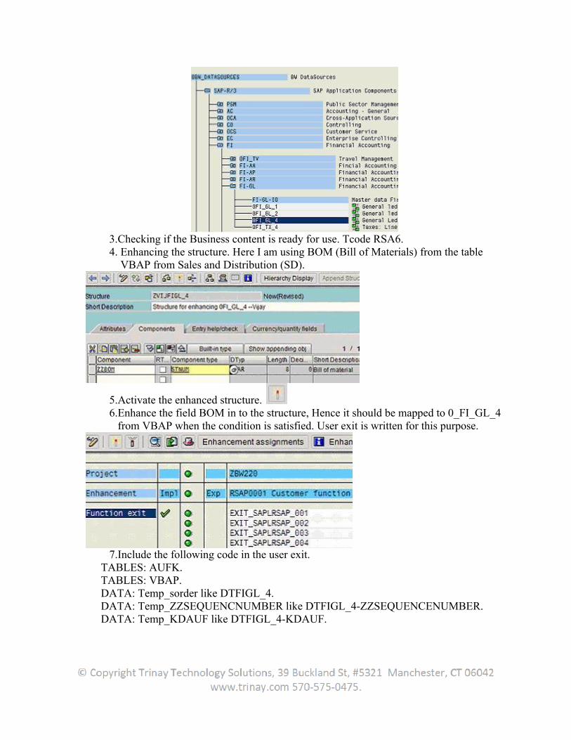
3.Checking if the Business content is ready for use. Tcode RSA6.4. Enhancing the structure. Here I am using BOM (Bill of Materials) from the table VBAP from Sales and Distribution (SD).
5.Activate the enhanced structure. 6.Enhance the field BOM in to the structure, Hence it should be mapped to 0_FI_GL_4 from VBAP when the condition is satisfied. User exit is written for this purpose.
7.Include the following code in the user exit. TABLES: AUFK. TABLES: VBAP. DATA: Temp_sorder like DTFIGL_4. DATA: Temp_ZZSEQUENCNUMBER like DTFIGL_4-ZZSEQUENCENUMBER. DATA: Temp_KDAUF like DTFIGL_4-KDAUF.
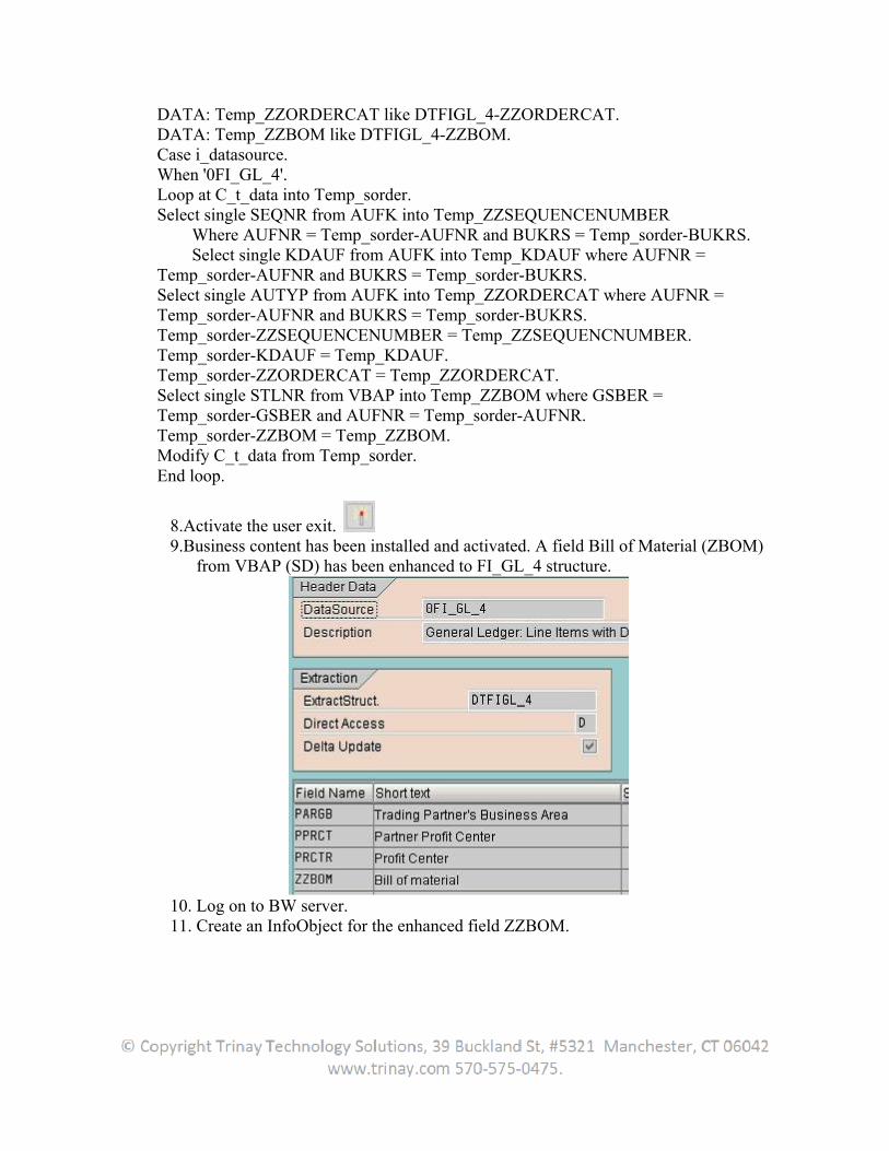
DATA: Temp_ZZORDERCAT like DTFIGL_4-ZZORDERCAT. DATA: Temp_ZZBOM like DTFIGL_4-ZZBOM.Case i_datasource. When '0FI_GL_4'. Loop at C_t_data into Temp_sorder. Select single SEQNR from AUFK into Temp_ZZSEQUENCENUMBER Where AUFNR = Temp_sorder-AUFNR and BUKRS = Temp_sorder-BUKRS. Select single KDAUF from AUFK into Temp_KDAUF where AUFNR = Temp_sorder-AUFNR and BUKRS = Temp_sorder-BUKRS. Select single AUTYP from AUFK into Temp_ZZORDERCAT where AUFNR = Temp_sorder-AUFNR and BUKRS = Temp_sorder-BUKRS. Temp_sorder-ZZSEQUENCENUMBER = Temp_ZZSEQUENCNUMBER. Temp_sorder-KDAUF = Temp_KDAUF. Temp_sorder-ZZORDERCAT = Temp_ZZORDERCAT. Select single STLNR from VBAP into Temp_ZZBOM where GSBER = Temp_sorder-GSBER and AUFNR = Temp_sorder-AUFNR. Temp_sorder-ZZBOM = Temp_ZZBOM. Modify C_t_data from Temp_sorder. End loop.
8.Activate the user exit. 9.Business content has been installed and activated. A field Bill of Material (ZBOM)
from VBAP (SD) has been enhanced to FI_GL_4 structure.
10. Log on to BW server. 11. Create an InfoObject for the enhanced field ZZBOM.
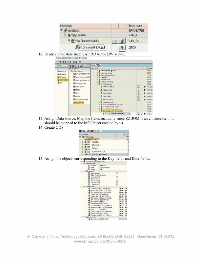
12. Replicate the data from SAP R/3 to the BW server.
13. Assign Data source. Map the fields manually since ZZBOM is an enhancement, it should be mapped to the InfoObject created by us.
14. Create ODS.
15. Assign the objects corresponding to the Key fields and Data fields.
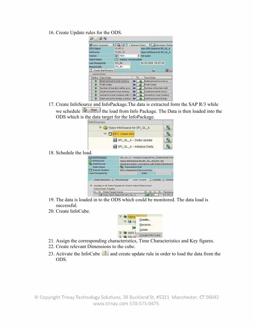
16. Create Update rules for the ODS.
17. Create InfoSource and InfoPackage.The data is extracted form the SAP R/3 while
we schedule the load from Info Package. The Data is then loaded into the ODS which is the data target for the InfoPackage.
18. Schedule the load.
19. The data is loaded in to the ODS which could be monitored. The data load is successful.
20. Create InfoCube.
21. Assign the corresponding characteristics, Time Characteristics and Key figures. 22. Create relevant Dimensions to the cube.
23. Activate the InfoCube and create update rule in order to load the data from the ODS.
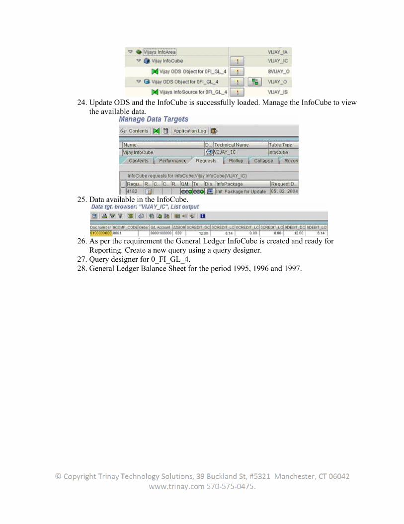
24. Update ODS and the InfoCube is successfully loaded. Manage the InfoCube to view the available data.
25. Data available in the InfoCube.
26. As per the requirement the General Ledger InfoCube is created and ready for Reporting. Create a new query using a query designer.
27. Query designer for 0_FI_GL_4. 28. General Ledger Balance Sheet for the period 1995, 1996 and 1997.
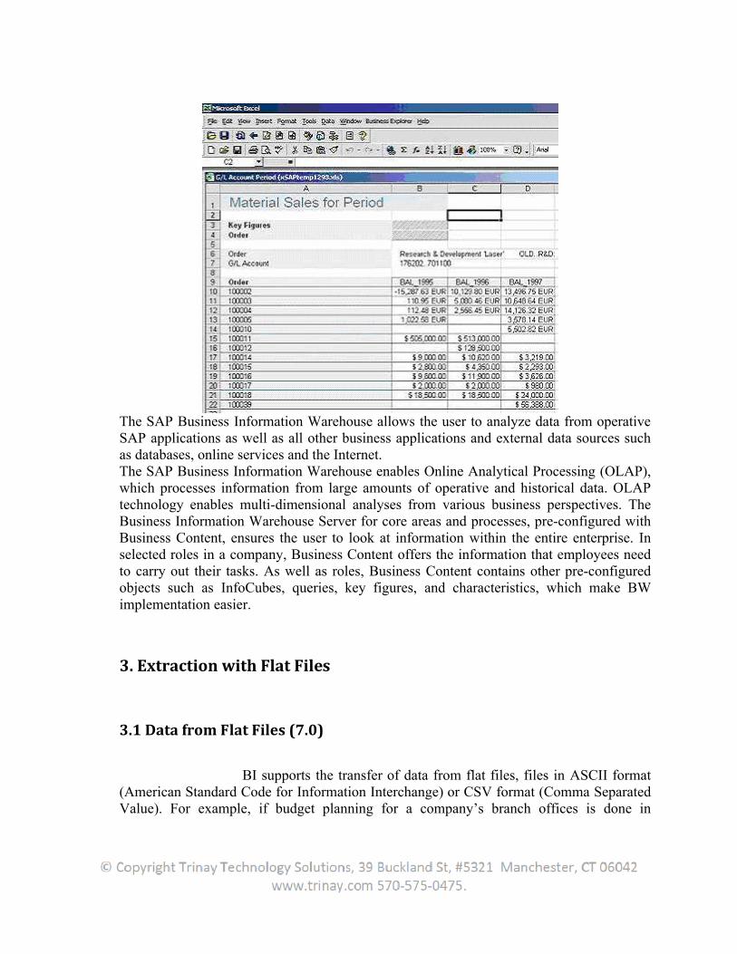
The SAP Business Information Warehouse allows the user to analyze data from operative SAP applications as well as all other business applications and external data sources such as databases, online services and the Internet.The SAP Business Information Warehouse enables Online Analytical Processing (OLAP), which processes information from large amounts of operative and historical data. OLAP technology enables multi-dimensional analyses from various business perspectives. The Business Information Warehouse Server for core areas and processes, pre-configured with Business Content, ensures the user to look at information within the entire enterprise. In selected roles in a company, Business Content offers the information that employees need to carry out their tasks. As well as roles, Business Content contains other pre-configured objects such as InfoCubes, queries, key figures, and characteristics, which make BW implementation easier.
3. Extraction with Flat Files
3.1 Data from Flat Files (7.0)
BI supports the transfer of data from flat files, files in ASCII format (American Standard Code for Information Interchange) or CSV format (Comma Separated Value). For example, if budget planning for a company’s branch offices is done in
Microsoft Excel, this planning data can be loaded into BI so that a plan-actual comparison can be performed. The data for the flat file can be transferred to BI from a workstation or from an application server.
1. The user defines a file source system.2. The user creates a DataSource in BI, defining the metadata for the user file in BI.3. The user creates an InfoPackage that includes the parameters for data transfer to the
PSA.
3.2 Data from Flat Files (3.x)
The metadata update takes place in DataSource maintenance of BI.Definition and updating of metadata, that is, the DataSource is done manually for flat files in SAP BW. The user can find more information about this, as well as about creating InfoSources for flat files under:
Flexibly Updating Data from Flat Files Updating Master Data from a Flat File Uploading Hierarchies from Flat Files
The structure of the flat file and the metadata (transfer structure of the DataSource) defined in SAP BW have to correspond to one another to enable correct data transfer. Make especially sure that the sequence of the InfoObjects corresponds to the sequence of the columns in the flat file. The transfer of data to SAP BW takes place via a file interface. Determine the parameters for data transfer in an InfoPackage and schedule the data request. The user can find more information under Maintaining InfoPackages Procedure for Flat Files.For flat files, delta transfer in the case of flexible updating is supported. The user can establish if and which delta processes are supported during maintenance of the transfer structure. With additive deltas, the extracted data is added in BW. DataSources with this delta process type can supply both ODS objects and InfoCubes with data. During transfer of the new status for modified records, the values are overwritten in BW. DataSources with this delta process type can write the data into ODS objects and master data tables.
3.3 Extracting Transaction and Master Data using Flat Files
Go to T-CODE SE11 and select the radio button TRANSACTION DATA and give the some technical name and click on CREATE button.
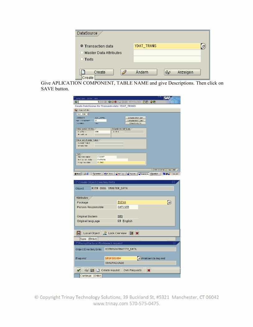
Give APLICATION COMPONENT, TABLE NAME and give Descriptions. Then click on SAVE button.
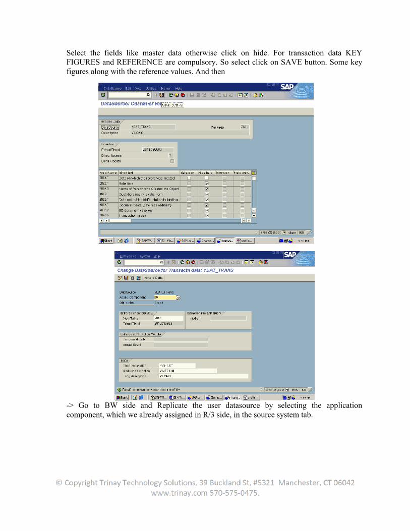
Select the fields like master data otherwise click on hide. For transaction data KEY FIGURES and REFERENCE are compulsory. So select click on SAVE button. Some key figures along with the reference values. And then
-> Go to BW side and Replicate the user datasource by selecting the application component, which we already assigned in R/3 side, in the source system tab.
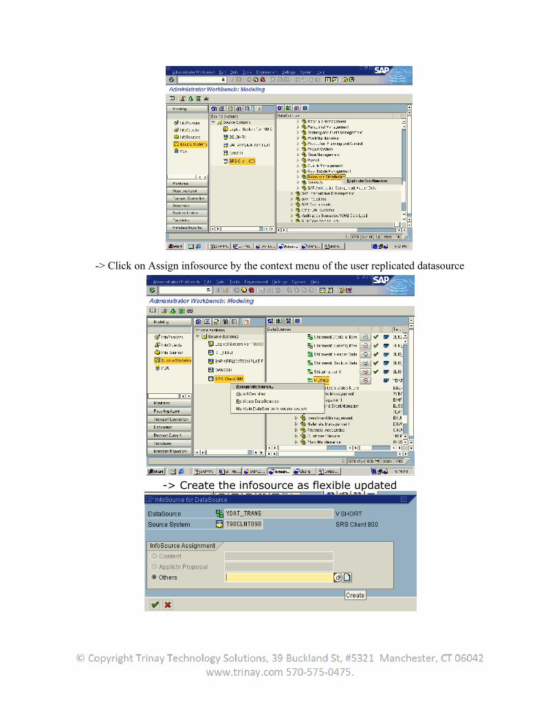
-> Click on Assign infosource by the context menu of the user replicated datasource
-> Create the infosource as flexible updated
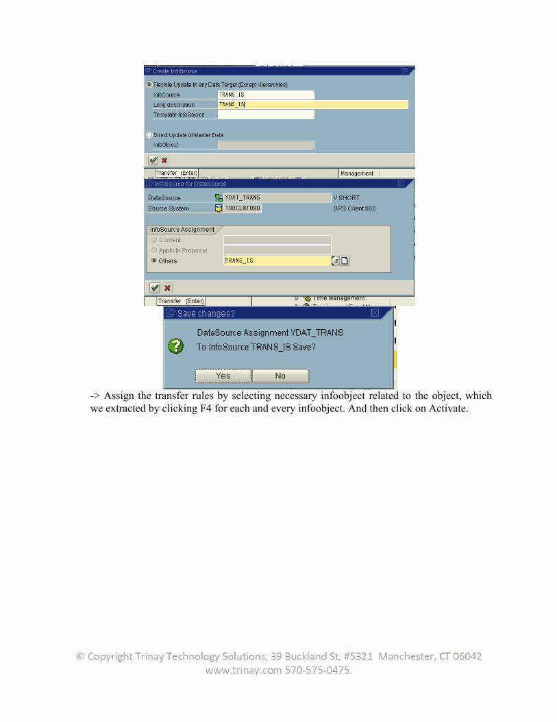
-> Assign the transfer rules by selecting necessary infoobject related to the object, which we extracted by clicking F4 for each and every infoobject. And then click on Activate.
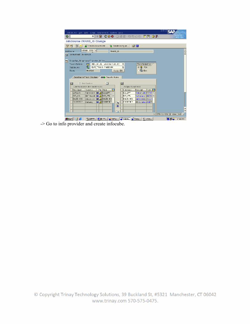
-> Go to info provider and create infocube.
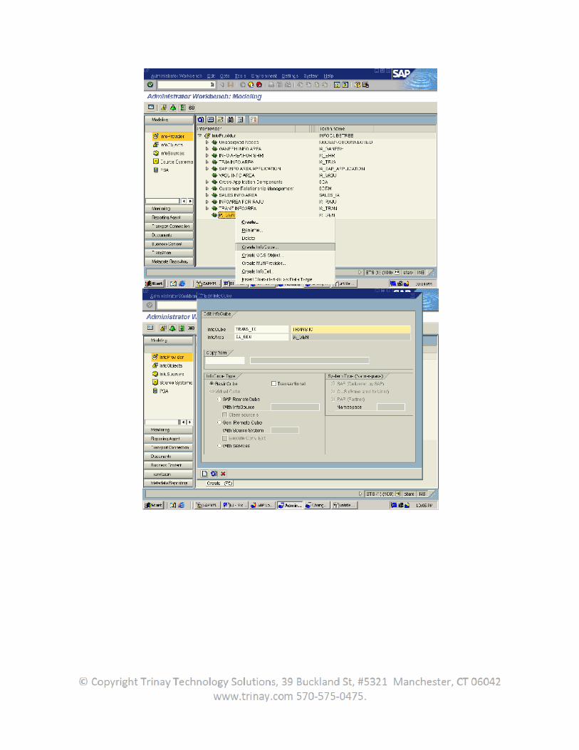
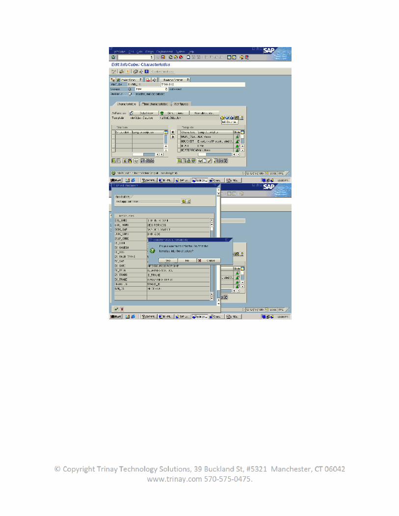
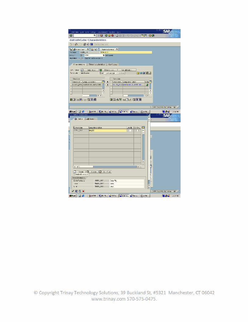
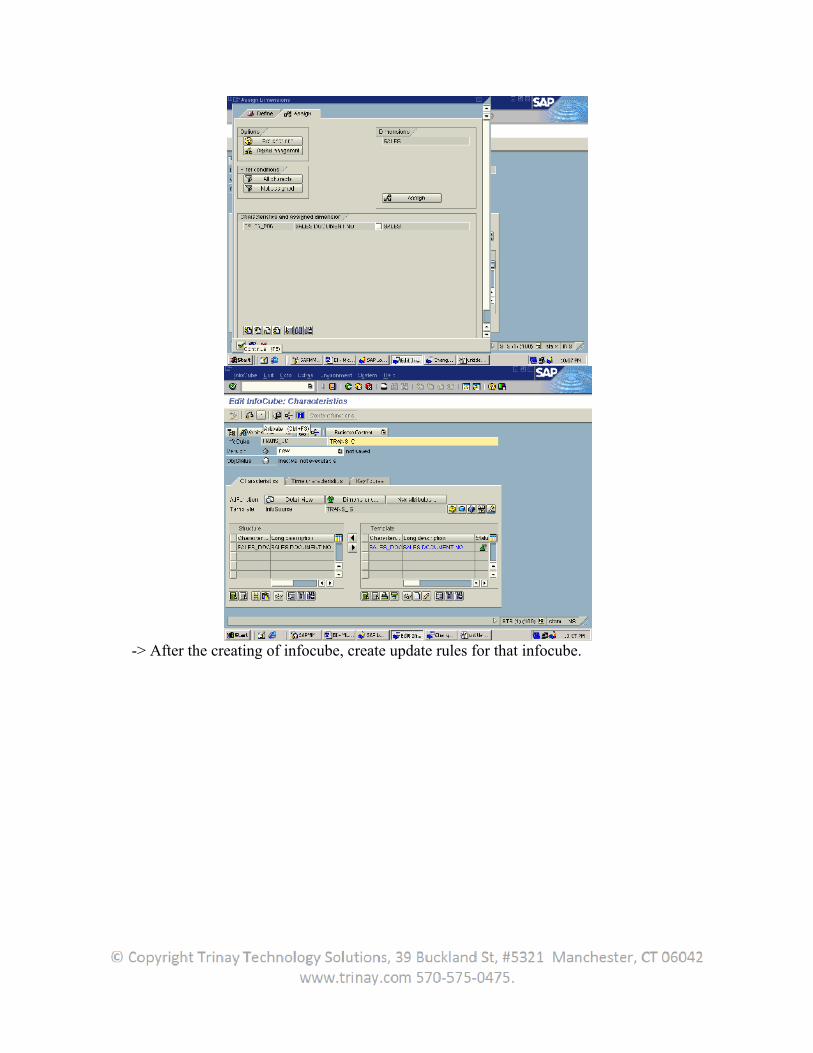
-> After the creating of infocube, create update rules for that infocube.
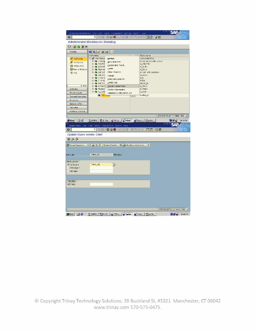
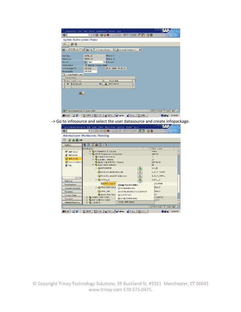
-> Go to infosource and select the user datasource and create infopackage.
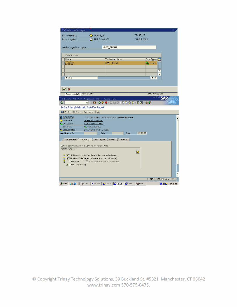
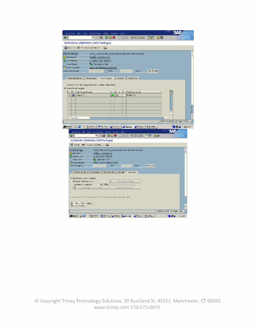
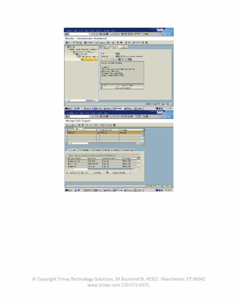
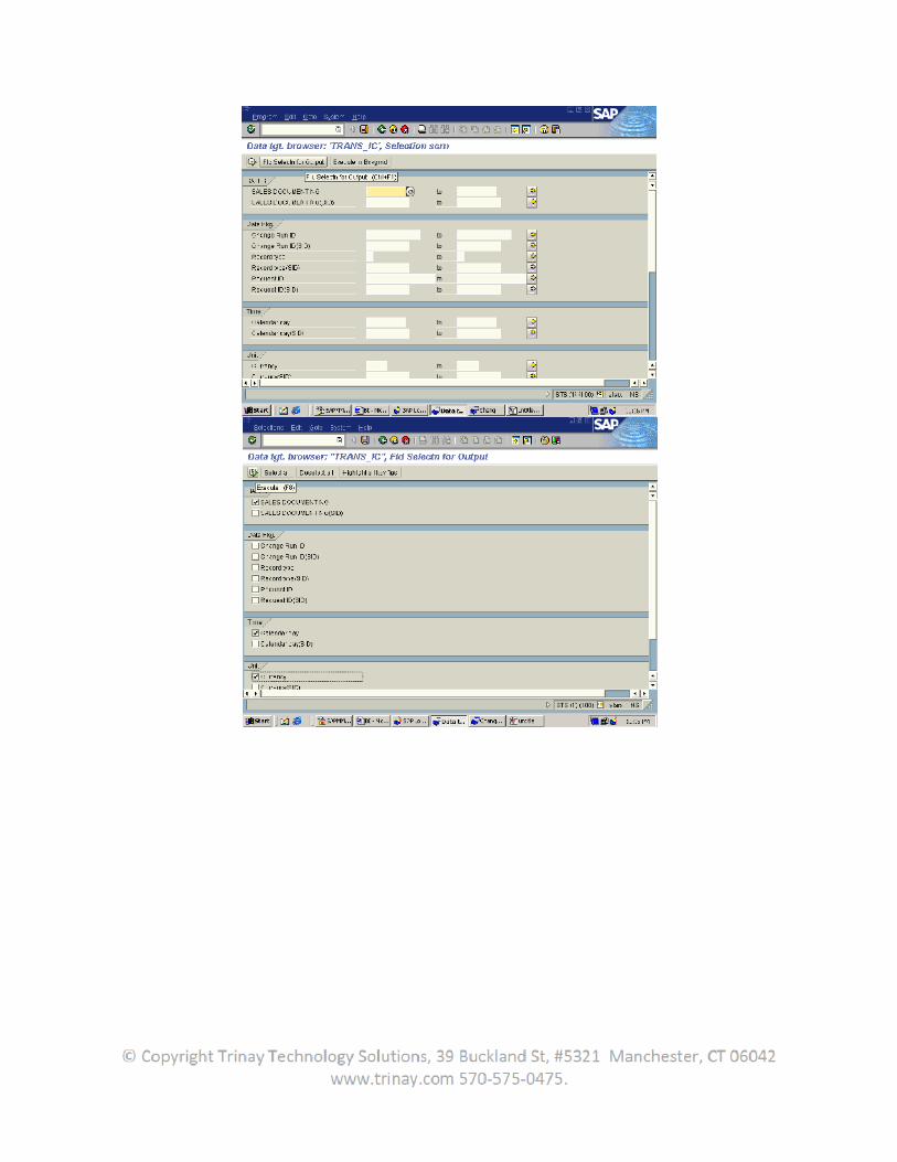
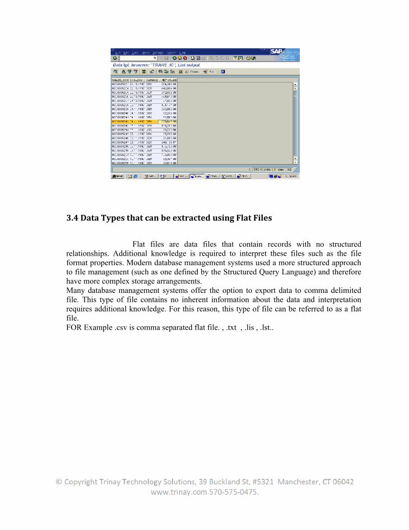
3.4 Data Types that can be extracted using Flat Files
Flat files are data files that contain records with no structured relationships. Additional knowledge is required to interpret these files such as the file format properties. Modern database management systems used a more structured approach to file management (such as one defined by the Structured Query Language) and therefore have more complex storage arrangements.Many database management systems offer the option to export data to comma delimited file. This type of file contains no inherent information about the data and interpretation requires additional knowledge. For this reason, this type of file can be referred to as a flat file.FOR Example .csv is comma separated flat file. , .txt , .lis , .lst..
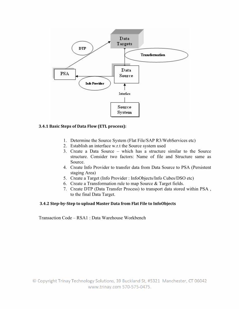
3.4.1 Basic Steps of Data Flow (ETL process):
1. Determine the Source System (Flat File/SAP R3/WebServices etc) 2. Establish an interface w.r.t the Source system used 3. Create a Data Source – which has a structure similar to the Source
structure. Consider two factors: Name of file and Structure same as Source.
4. Create Info Provider to transfer data from Data Source to PSA (Persistent staging Area)
5. Create a Target (Info Provider : InfoObjects/Info Cubes/DSO etc) 6. Create a Transformation rule to map Source & Target fields. 7. Create DTP (Data Transfer Process) to transport data stored within PSA ,
to the final Data Target.
3.4.2 Step-by-Step to upload Master Data from Flat File to InfoObjects
Transaction Code – RSA1 : Data Warehouse Workbench
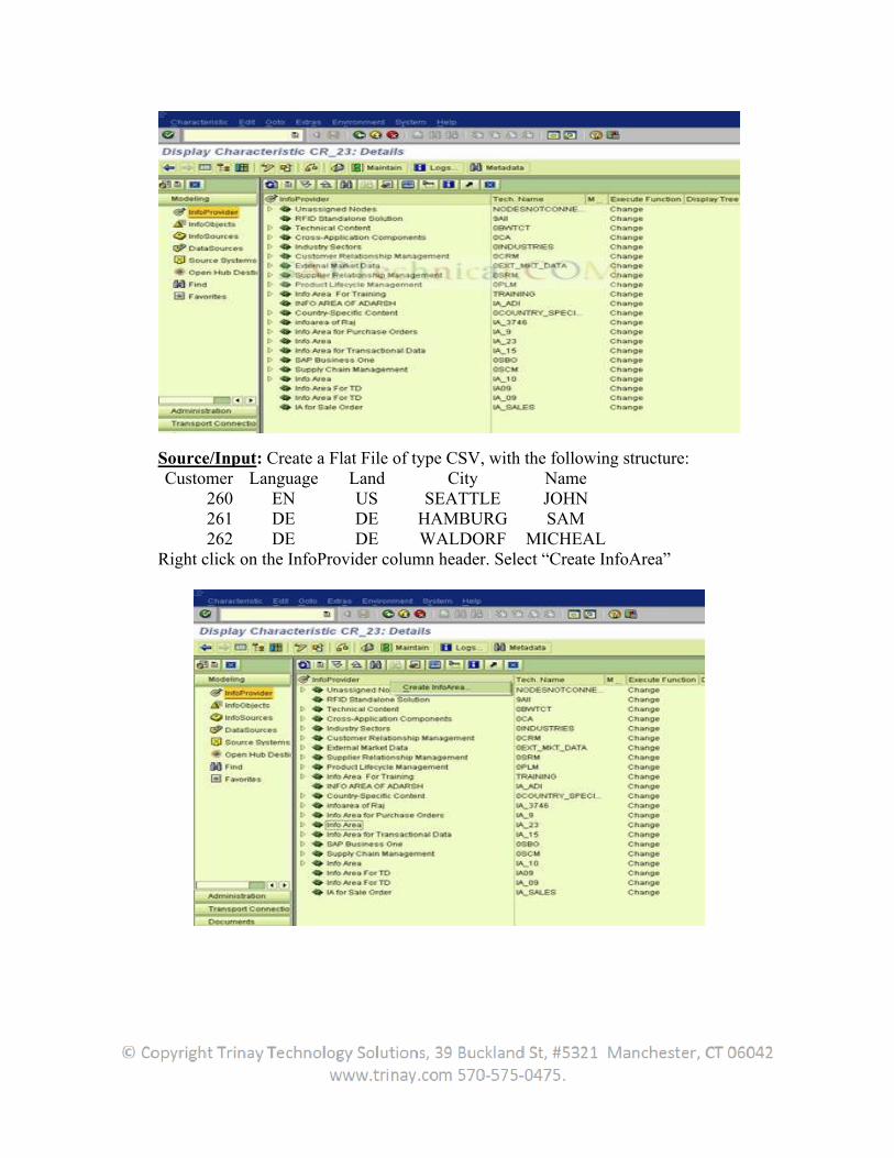
Source/Input: Create a Flat File of type CSV, with the following structure: Customer Language Land City Name
260 EN US SEATTLE JOHN 261 DE DE HAMBURG SAM 262 DE DE WALDORF MICHEAL
Right click on the InfoProvider column header. Select “Create InfoArea”
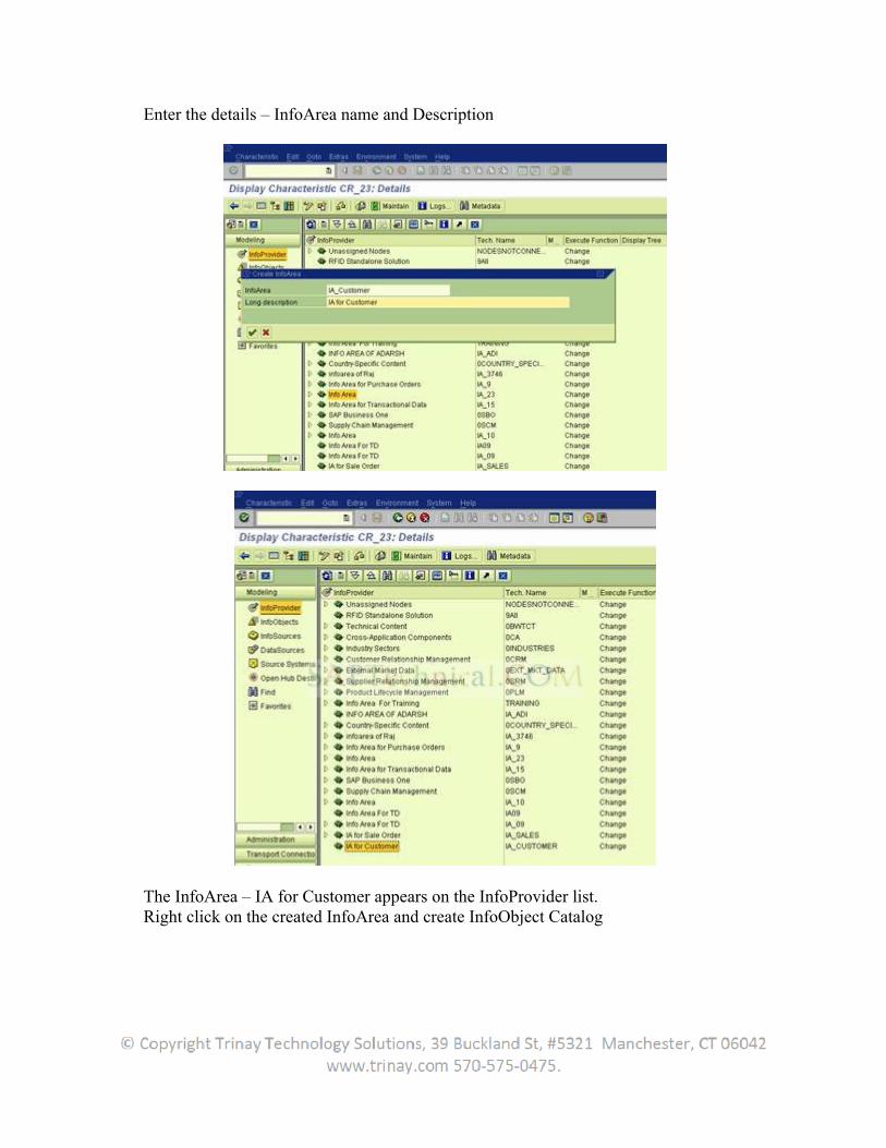
Enter the details – InfoArea name and Description
The InfoArea – IA for Customer appears on the InfoProvider list. Right click on the created InfoArea and create InfoObject Catalog
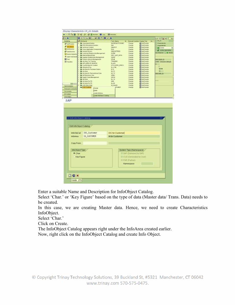
Enter a suitable Name and Description for InfoObject Catalog. Select ‘Char.’ or ‘Key Figure’ based on the type of data (Master data/ Trans. Data) needs to be created. In this case, we are creating Master data. Hence, we need to create Characteristics InfoObject. Select ‘Char.’ Click on Create. The InfoObject Catalog appears right under the InfoArea created earlier. Now, right click on the InfoObject Catalog and create Info Object.
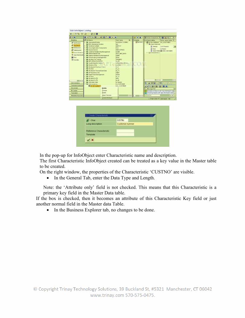
In the pop-up for InfoObject enter Characteristic name and description. The first Characteristic InfoObject created can be treated as a key value in the Master table to be created. On the right window, the properties of the Characteristic ‘CUSTNO’ are visible.
In the General Tab, enter the Data Type and Length.
Note: the ‘Attribute only’ field is not checked. This means that this Characteristic is a primary key field in the Master Data table.
If the box is checked, then it becomes an attribute of this Characteristic Key field or just another normal field in the Master data Table.
In the Business Explorer tab, no changes to be done.

Save + Activate => P tables gets created In the Master data/texts tab,
Check “With Master data”, to create a Master Data table, having naming convention /BIC/P<characteristic name>
Check “With Texts”, to create a corresponding Text table for this Master Data table with two default fields – Language & Description.
Select ‘short/medium/long texts’, also ‘texts language dependent’. Select “Char is InfoProvider” (as our InfoObject is our target in this
scenario). Enter the InfoArea in the box below.
In the Attribute tab, enter the fields (non-key fields) that need to be maintained within the Master Data table.
Ex: Customer Id – primary key field Land City
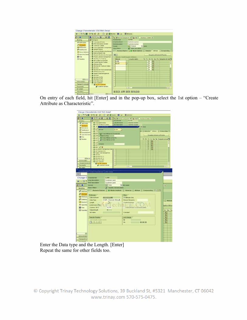
On entry of each field, hit [Enter] and in the pop-up box, select the 1st option – “Create Attribute as Characteristic”.
Enter the Data type and the Length. [Enter] Repeat the same for other fields too.
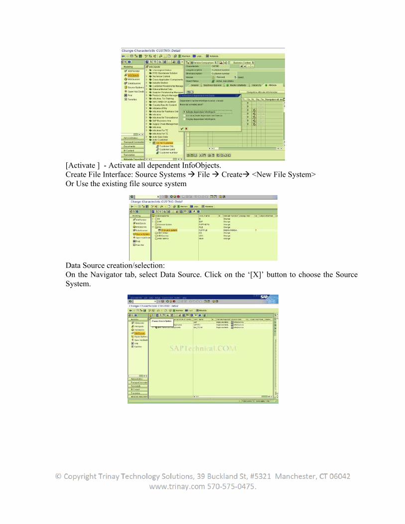
[Activate ] - Activate all dependent InfoObjects. Create File Interface: Source Systems File Create <New File System> Or Use the existing file source system
Data Source creation/selection: On the Navigator tab, select Data Source. Click on the ‘[X]’ button to choose the Source System.
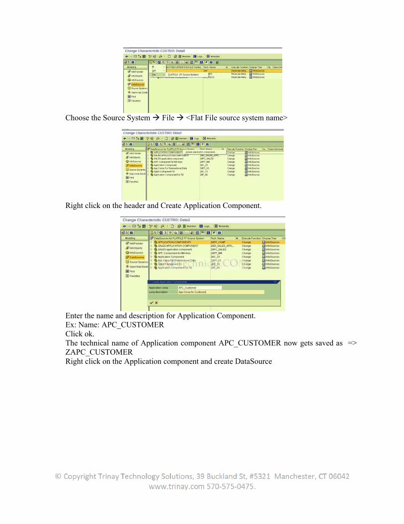
Choose the Source System File <Flat File source system name>
Right click on the header and Create Application Component.
Enter the name and description for Application Component. Ex: Name: APC_CUSTOMER Click ok. The technical name of Application component APC_CUSTOMER now gets saved as => ZAPC_CUSTOMER Right click on the Application component and create DataSource
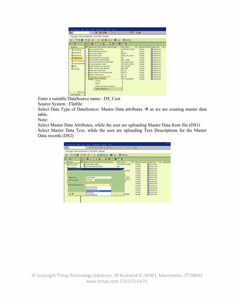
Enter a suitable DataSource name : DS_Cust Source System : Flatfile Select Data Type of DataSource: Master Data attributes as we are creating master data table. Note: Select Master Data Attributes, while the user are uploading Master Data from file (DS1) Select Master Data Text, while the user are uploading Text Descriptions for the Master Data records (DS2)
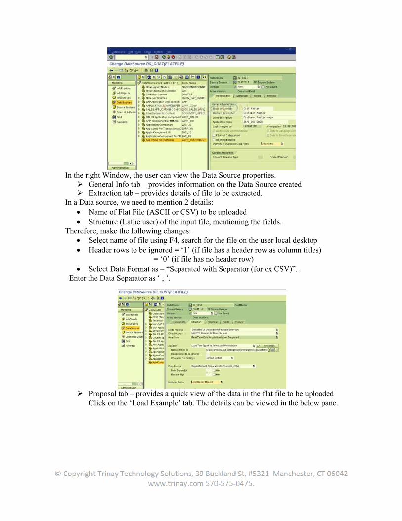
In the right Window, the user can view the Data Source properties. General Info tab – provides information on the Data Source created Extraction tab – provides details of file to be extracted.
In a Data source, we need to mention 2 details: Name of Flat File (ASCII or CSV) to be uploaded Structure (Lathe user) of the input file, mentioning the fields.
Therefore, make the following changes: Select name of file using F4, search for the file on the user local desktop Header rows to be ignored = ‘1’ (if file has a header row as column titles)
= ‘0’ (if file has no header row) Select Data Format as – “Separated with Separator (for ex CSV)”.
Enter the Data Separator as ‘ , ‘.
Proposal tab – provides a quick view of the data in the flat file to be uploaded Click on the ‘Load Example’ tab. The details can be viewed in the below pane.

Fields tab – provides details of all fields used to create a data structure, to map with the fields from Source file.
In the Template Info field, enter the field names (characteristics/attributes). [Enter] or [Save] [Copy] : all properties of the characteristics ( ex: data types, length etc) are
copied here.
Note: the fields 0LANGU and 0TXTSH are the standard SAP defined characteristics InfoObjects. [Save] [Activate]
Preview tab – gives a preview of data on flat file loaded onto a structure. Click on “Read Preview Data”
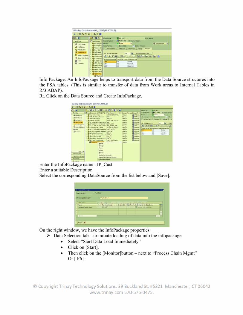
Info Package: An InfoPackage helps to transport data from the Data Source structures into the PSA tables. (This is similar to transfer of data from Work areas to Internal Tables in R/3 ABAP). Rt. Click on the Data Source and Create InfoPackage.
Enter the InfoPackage name : IP_Cust Enter a suitable Description Select the corresponding DataSource from the list below and [Save].
On the right window, we have the InfoPackage properties: Data Selection tab – to initiate loading of data into the infopackage
Select “Start Data Load Immediately” Click on [Start]. Then click on the [Monitor]button – next to “Process Chain Mgmt”
Or [ F6].
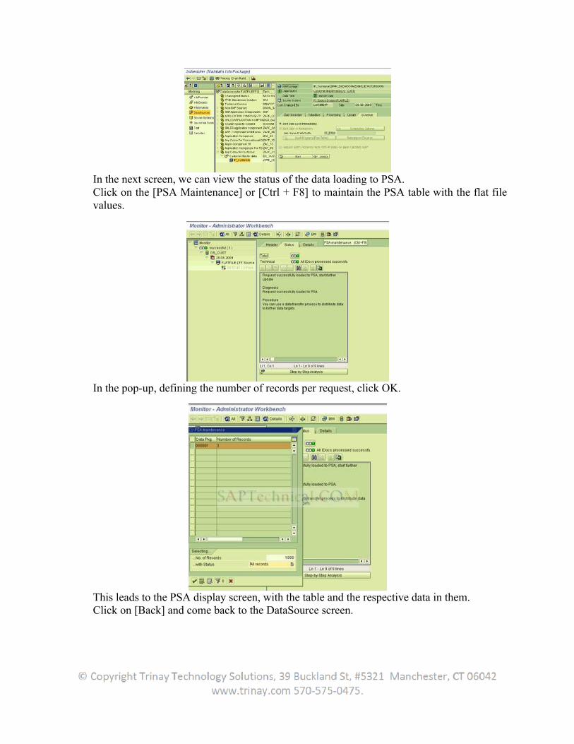
In the next screen, we can view the status of the data loading to PSA. Click on the [PSA Maintenance] or [Ctrl + F8] to maintain the PSA table with the flat file values.
In the pop-up, defining the number of records per request, click OK.
This leads to the PSA display screen, with the table and the respective data in them. Click on [Back] and come back to the DataSource screen.
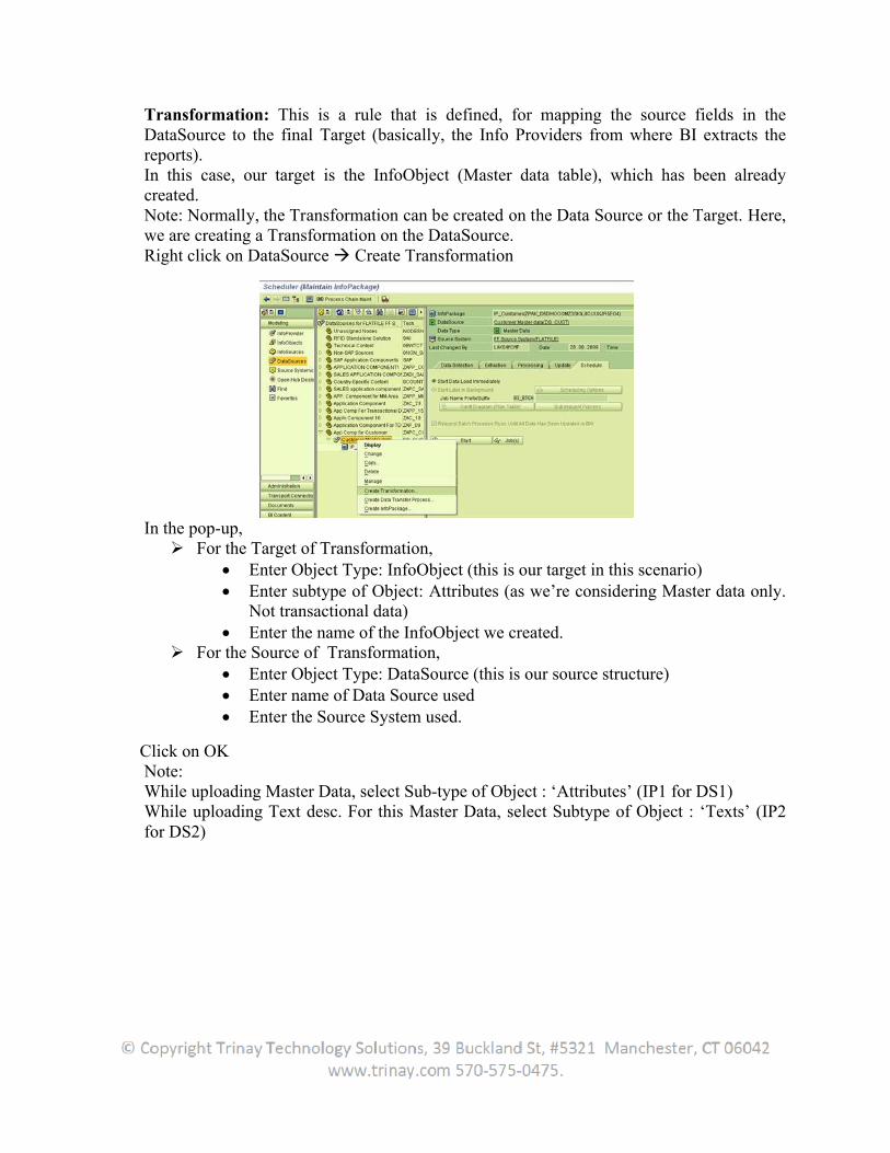
Transformation: This is a rule that is defined, for mapping the source fields in the DataSource to the final Target (basically, the Info Providers from where BI extracts the reports). In this case, our target is the InfoObject (Master data table), which has been already created. Note: Normally, the Transformation can be created on the Data Source or the Target. Here, we are creating a Transformation on the DataSource. Right click on DataSource Create Transformation
In the pop-up, For the Target of Transformation,
Enter Object Type: InfoObject (this is our target in this scenario) Enter subtype of Object: Attributes (as we’re considering Master data only.
Not transactional data) Enter the name of the InfoObject we created.
For the Source of Transformation, Enter Object Type: DataSource (this is our source structure) Enter name of Data Source used Enter the Source System used.
Click on OK Note: While uploading Master Data, select Sub-type of Object : ‘Attributes’ (IP1 for DS1) While uploading Text desc. For this Master Data, select Subtype of Object : ‘Texts’ (IP2 for DS2)
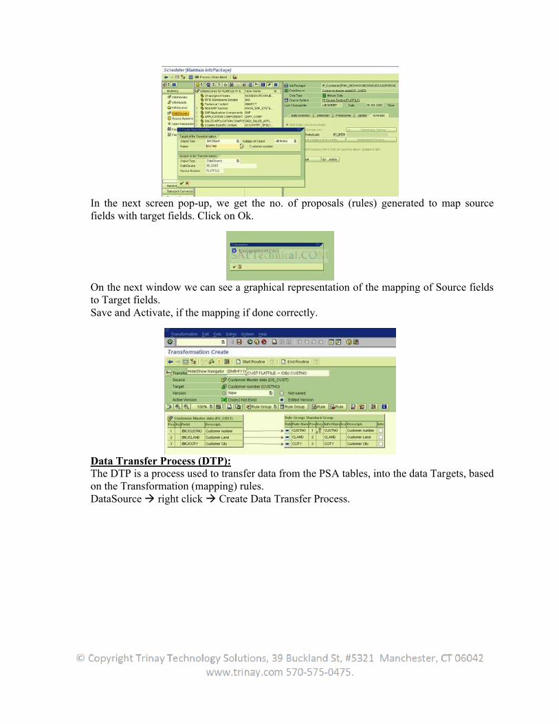
In the next screen pop-up, we get the no. of proposals (rules) generated to map source fields with target fields. Click on Ok.
On the next window we can see a graphical representation of the mapping of Source fields to Target fields. Save and Activate, if the mapping if done correctly.
Data Transfer Process (DTP): The DTP is a process used to transfer data from the PSA tables, into the data Targets, based on the Transformation (mapping) rules. DataSource right click Create Data Transfer Process.
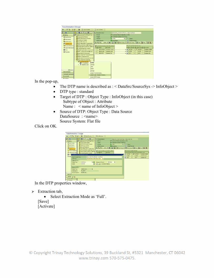
In the pop-up, The DTP name is described as : < DataSrc/SourceSys -> InfoObject > DTP type : standard Target of DTP : Object Type : InfoObject (in this case)
Subtype of Object : Attribute Name : < name of InfoObject >
Source of DTP: Object Type : Data SourceDataSource : <name> Source System: Flat file
Click on OK.
In the DTP properties window,
Extraction tab, Select Extraction Mode as ‘Full’.
[Save] [Activate]
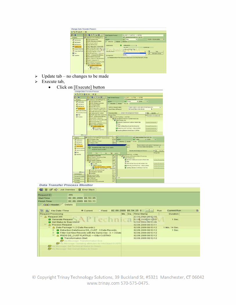
Update tab – no changes to be made Execute tab,
Click on [Execute] button
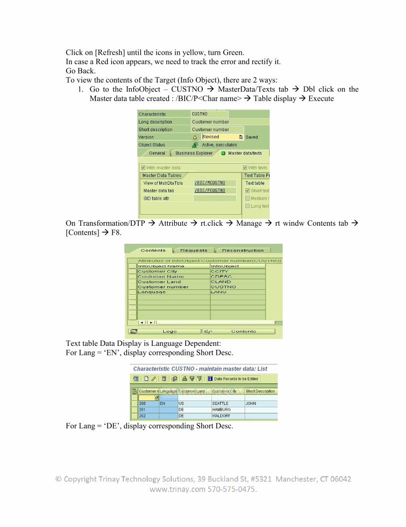
Click on [Refresh] until the icons in yellow, turn Green. In case a Red icon appears, we need to track the error and rectify it. Go Back. To view the contents of the Target (Info Object), there are 2 ways:
1. Go to the InfoObject – CUSTNO MasterData/Texts tab Dbl click on the Master data table created : /BIC/P<Char name> Table display Execute
On Transformation/DTP Attribute rt.click Manage rt windw Contents tab [Contents] F8.
Text table Data Display is Language Dependent: For Lang = ‘EN’, display corresponding Short Desc.
For Lang = ‘DE’, display corresponding Short Desc.
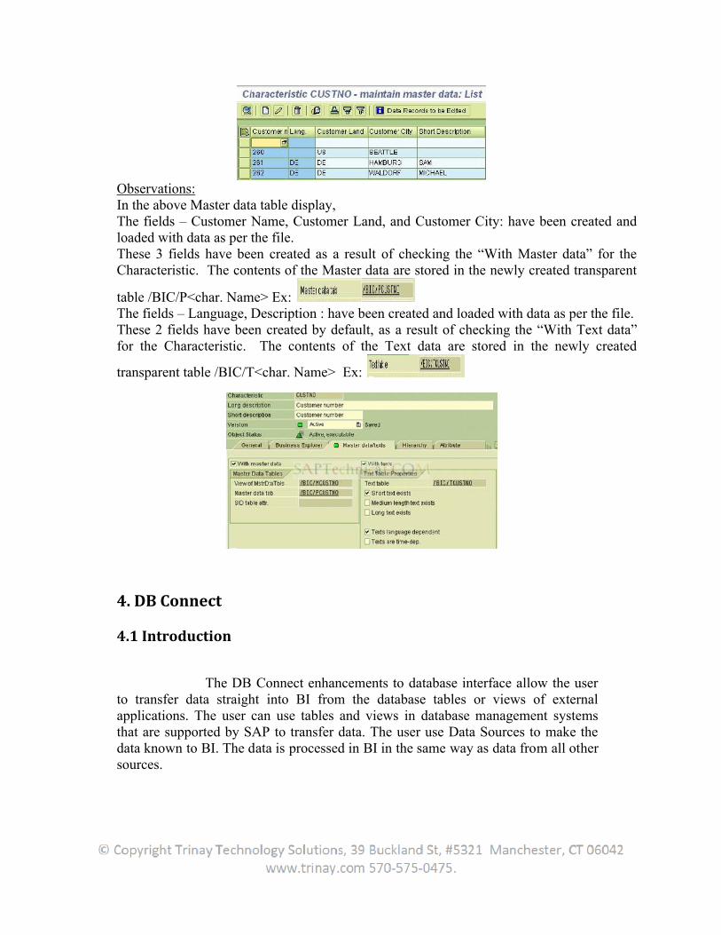
Observations: In the above Master data table display, The fields – Customer Name, Customer Land, and Customer City: have been created and loaded with data as per the file. These 3 fields have been created as a result of checking the “With Master data” for the Characteristic. The contents of the Master data are stored in the newly created transparent
table /BIC/P<char. Name> Ex: The fields – Language, Description : have been created and loaded with data as per the file. These 2 fields have been created by default, as a result of checking the “With Text data” for the Characteristic. The contents of the Text data are stored in the newly created
transparent table /BIC/T<char. Name> Ex:
4. DB Connect
4.1 Introduction
The DB Connect enhancements to database interface allow the userto transfer data straight into BI from the database tables or views of external applications. The user can use tables and views in database management systems that are supported by SAP to transfer data. The user use Data Sources to make the data known to BI. The data is processed in BI in the same way as data from all other sources.
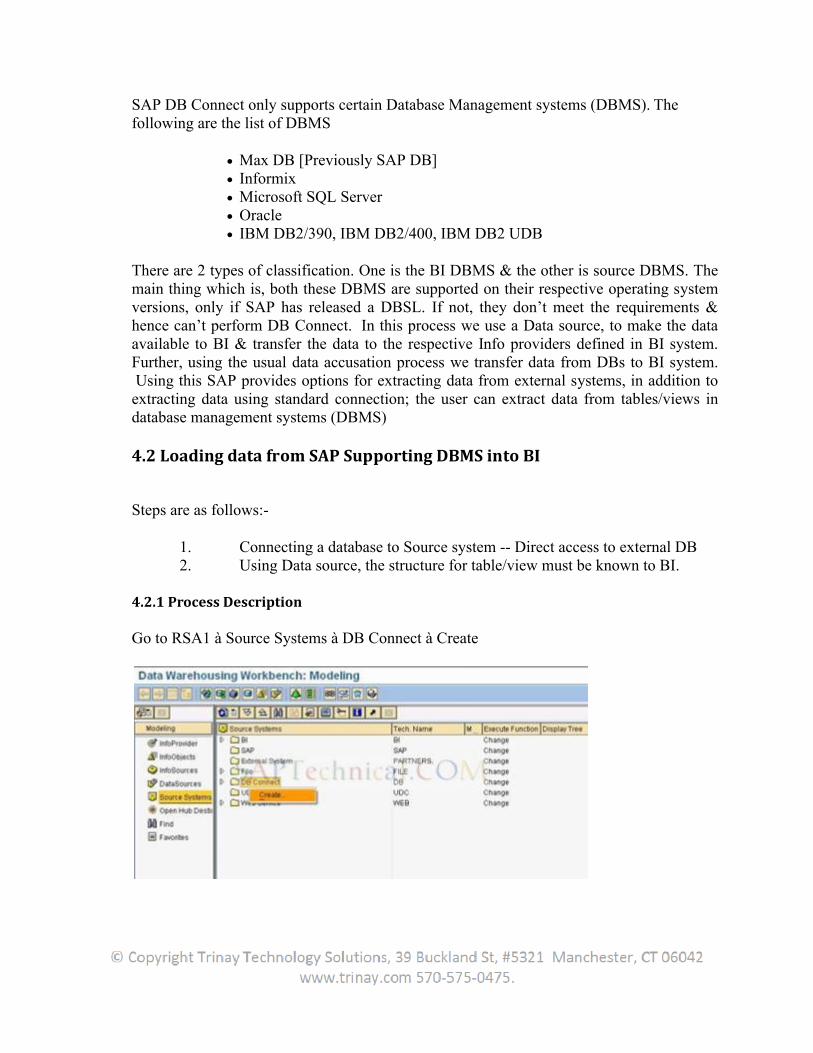
SAP DB Connect only supports certain Database Management systems (DBMS). The following are the list of DBMS
Max DB [Previously SAP DB] Informix Microsoft SQL Server Oracle IBM DB2/390, IBM DB2/400, IBM DB2 UDB
There are 2 types of classification. One is the BI DBMS & the other is source DBMS. The main thing which is, both these DBMS are supported on their respective operating system versions, only if SAP has released a DBSL. If not, they don’t meet the requirements & hence can’t perform DB Connect. In this process we use a Data source, to make the data available to BI & transfer the data to the respective Info providers defined in BI system. Further, using the usual data accusation process we transfer data from DBs to BI system. Using this SAP provides options for extracting data from external systems, in addition to extracting data using standard connection; the user can extract data from tables/views in database management systems (DBMS)
4.2 Loading data from SAP Supporting DBMS into BI
Steps are as follows:-
1. Connecting a database to Source system -- Direct access to external DB 2. Using Data source, the structure for table/view must be known to BI.
4.2.1 Process Description
Go to RSA1 à Source Systems à DB Connect à Create
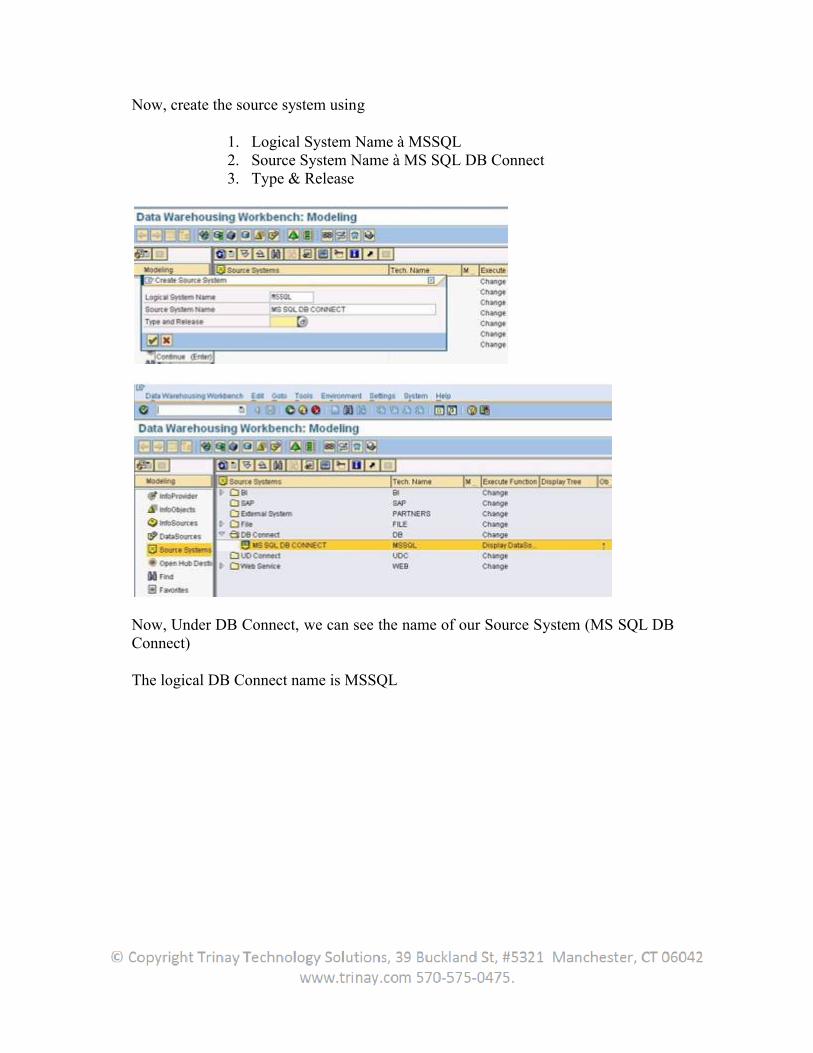
Now, create the source system using
1. Logical System Name à MSSQL 2. Source System Name à MS SQL DB Connect 3. Type & Release
Now, Under DB Connect, we can see the name of our Source System (MS SQL DB Connect)
The logical DB Connect name is MSSQL
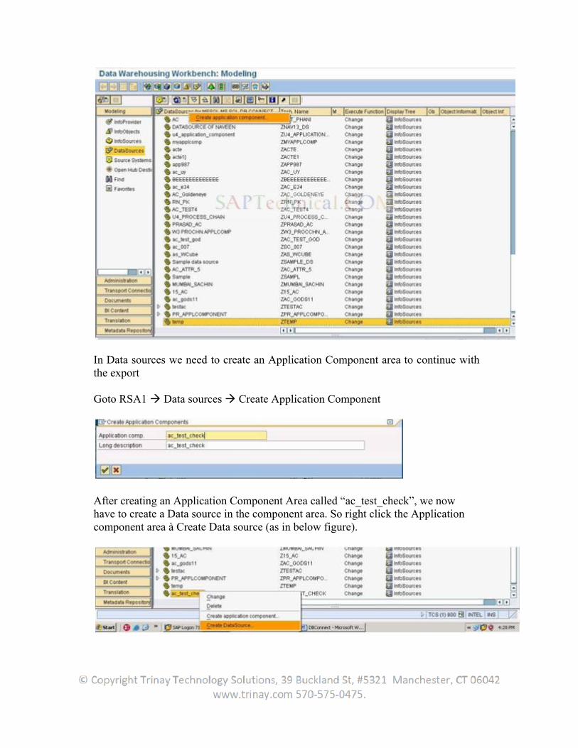
In Data sources we need to create an Application Component area to continue with the export
Goto RSA1 Data sources Create Application Component
After creating an Application Component Area called “ac_test_check”, we now have to create a Data source in the component area. So right click the Application component area à Create Data source (as in below figure).
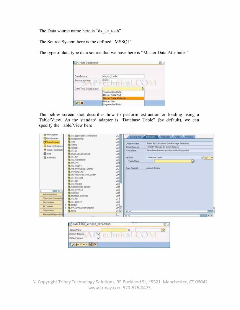
The Data source name here is “ds_ac_tech”
The Source System here is the defined “MSSQL”
The type of data type data source that we have here is “Master Data Attributes”
The below screen shot describes how to perform extraction or loading using a Table/View. As the standard adapter is “Database Table” (by default), we can specify the Table/View here
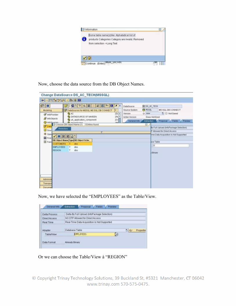
Now, choose the data source from the DB Object Names.
Now, we have selected the “EMPLOYEES” as the Table/View.
Or we can choose the Table/View à “REGION”
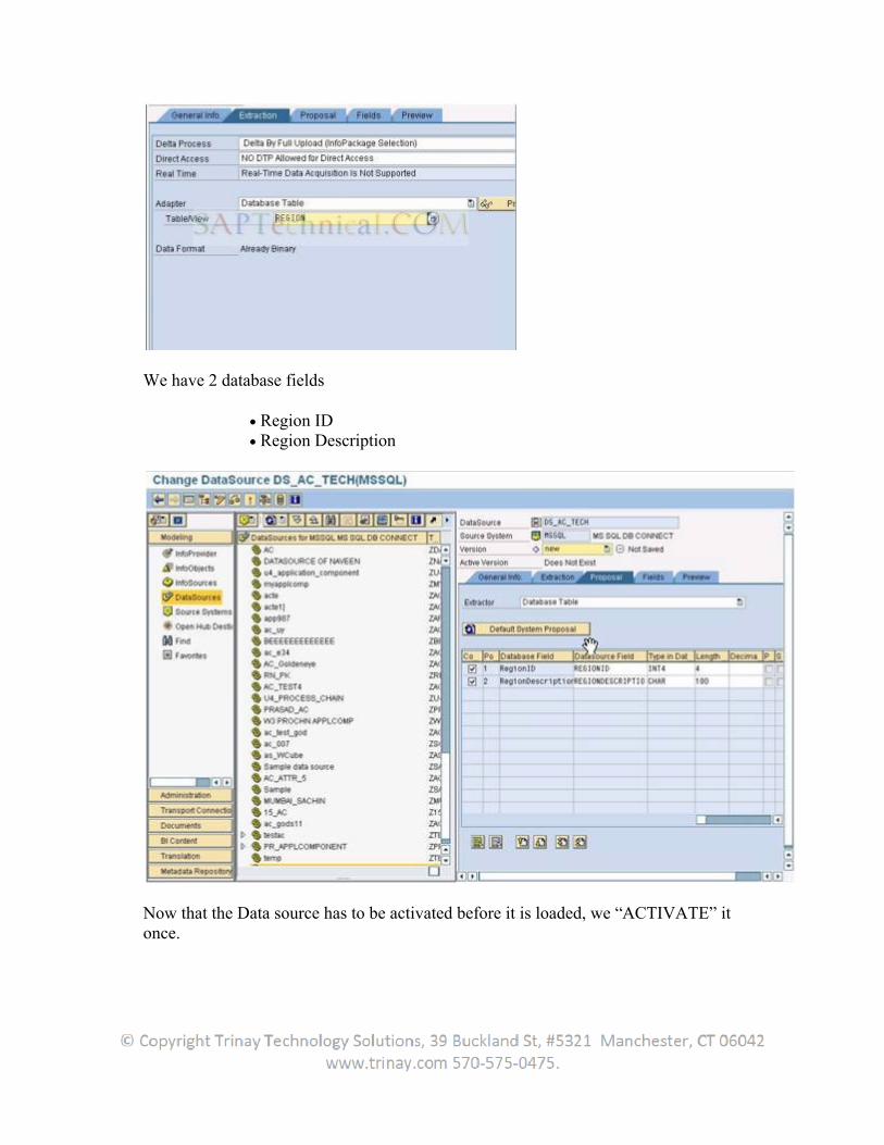
We have 2 database fields
Region ID Region Description
Now that the Data source has to be activated before it is loaded, we “ACTIVATE” it once.
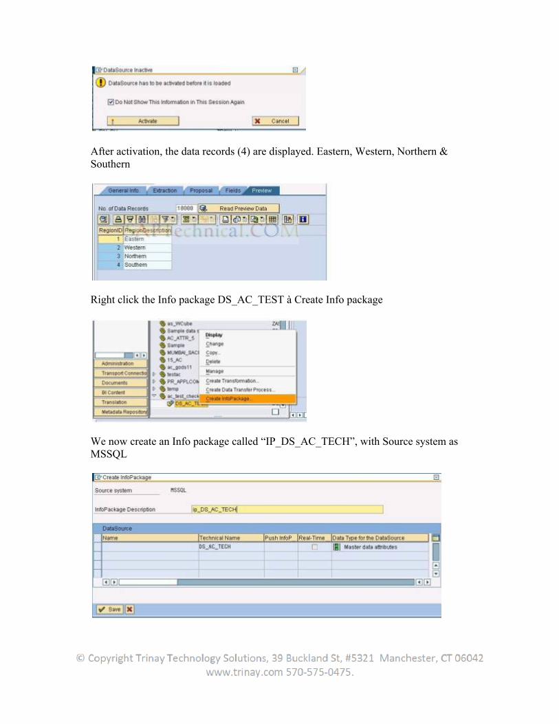
After activation, the data records (4) are displayed. Eastern, Western, Northern & Southern
Right click the Info package DS_AC_TEST à Create Info package
We now create an Info package called “IP_DS_AC_TECH”, with Source system as MSSQL
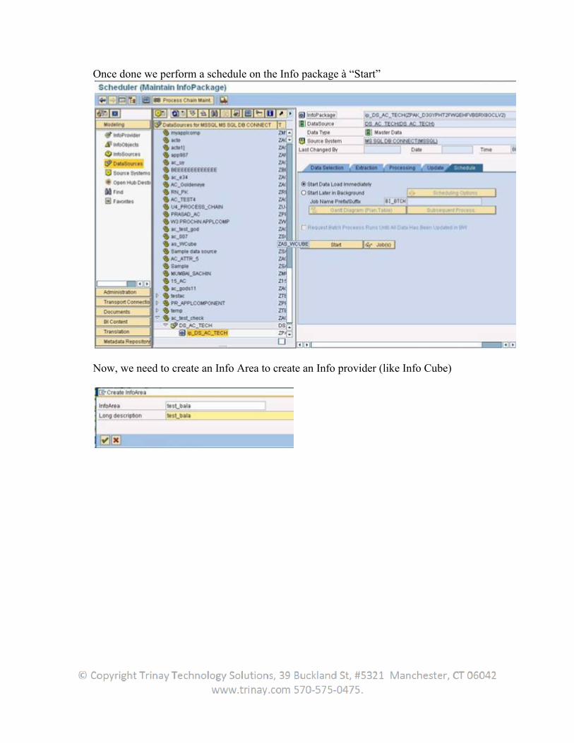
Once done we perform a schedule on the Info package à “Start”
Now, we need to create an Info Area to create an Info provider (like Info Cube)
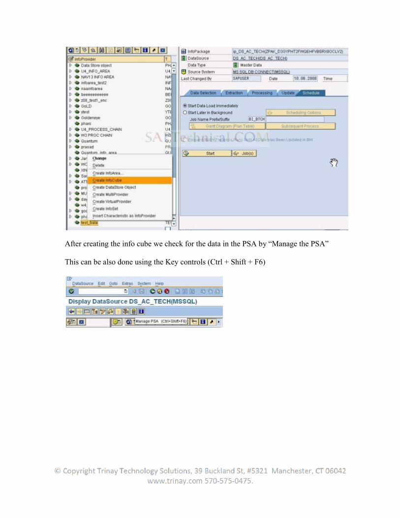
After creating the info cube we check for the data in the PSA by “Manage the PSA”
This can be also done using the Key controls (Ctrl + Shift + F6)
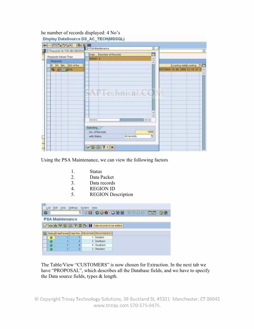
he number of records displayed: 4 No’s
Using the PSA Maintenance, we can view the following factors
1. Status 2. Data Packet 3. Data records 4. REGION ID 5. REGION Description
The Table/View “CUSTOMERS” is now chosen for Extraction. In the next tab we have “PROPOSAL”, which describes all the Database fields, and we have to specify the Data source fields, types & length.
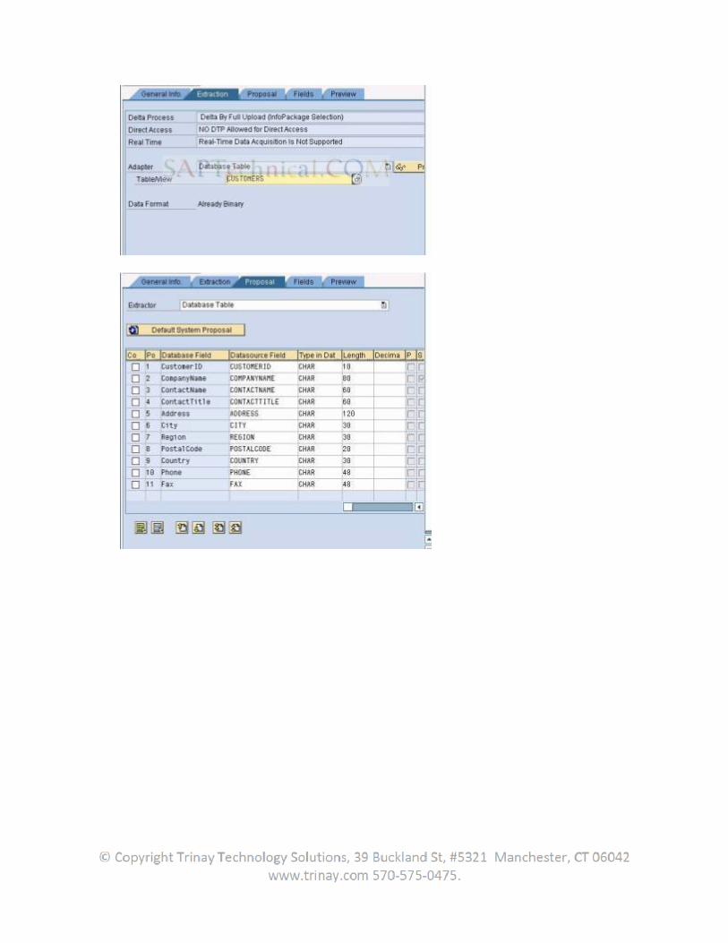
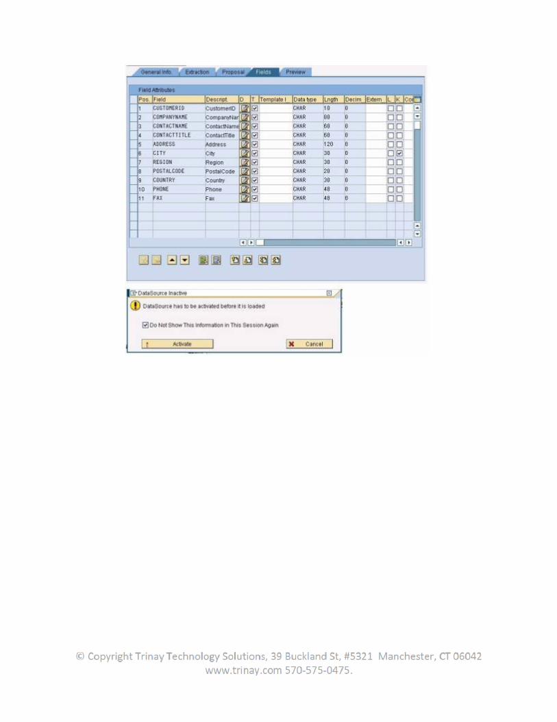
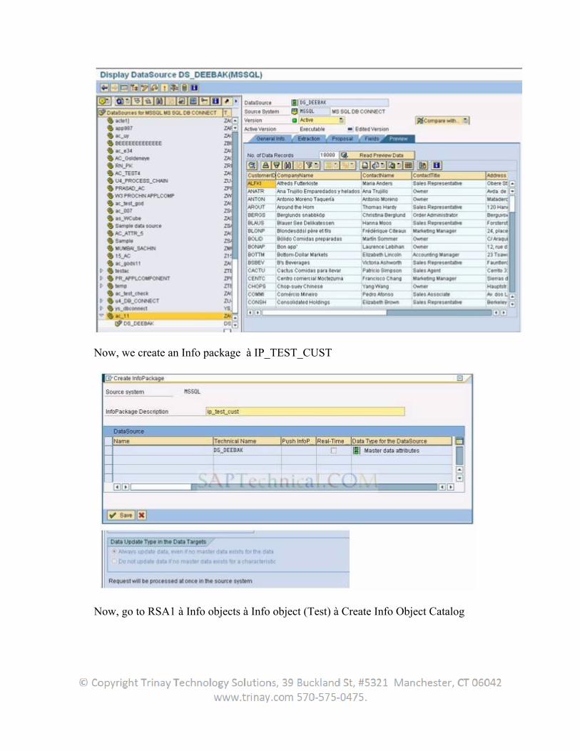
Now, we create an Info package à IP_TEST_CUST
Now, go to RSA1 à Info objects à Info object (Test) à Create Info Object Catalog
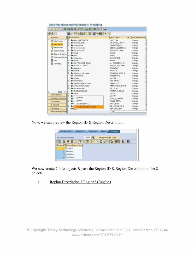
Now, we can preview the Region ID & Region Description.
We now create 2 Info objects & pass the Region ID & Region Description to the 2 objects.
1. Region Description à Region2 (Region)
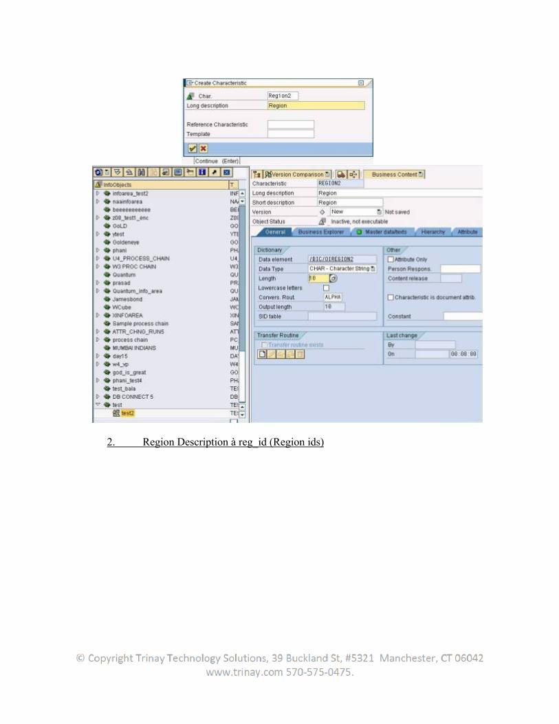
2. Region Description à reg_id (Region ids)
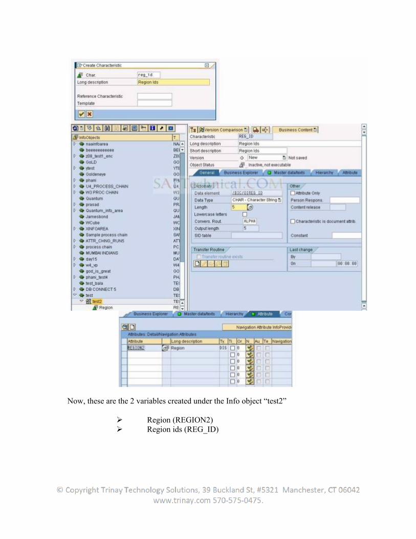
Now, these are the 2 variables created under the Info object “test2”
Region (REGION2) Region ids (REG_ID)
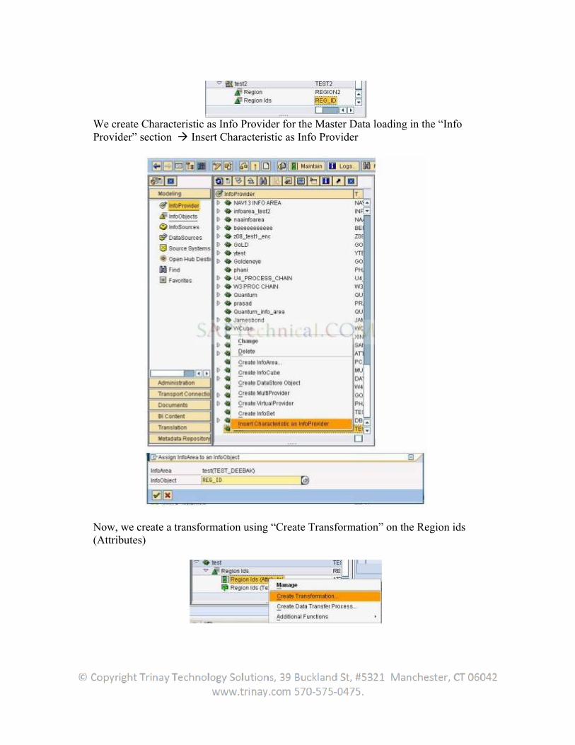
We create Characteristic as Info Provider for the Master Data loading in the “Info Provider” section Insert Characteristic as Info Provider
Now, we create a transformation using “Create Transformation” on the Region ids (Attributes)
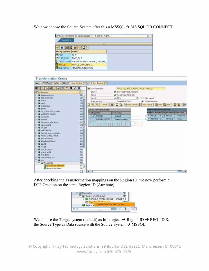
We now choose the Source System after this à MSSQL MS SQL DB CONNECT
After checking the Transformation mappings on the Region ID, we now perform a DTP Creation on the same Region ID (Attribute)
We choose the Target system (default) as Info object Region ID REG_ID & the Source Type as Data source with the Source System MSSQL
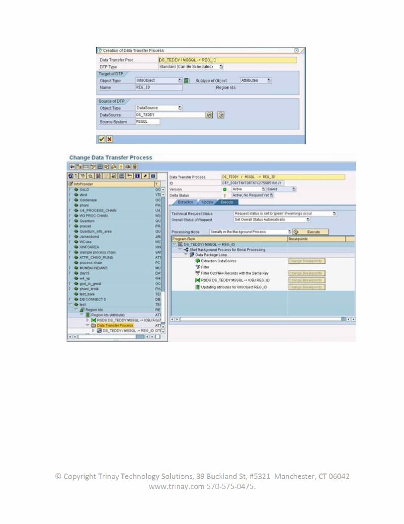
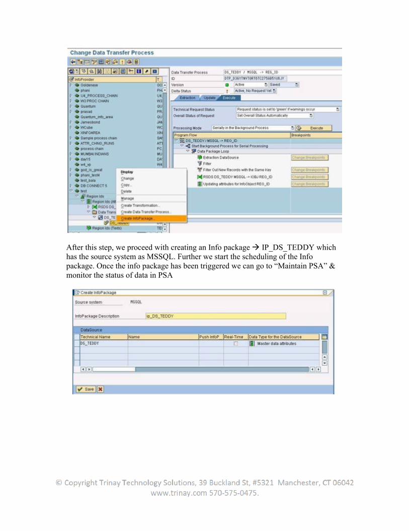
After this step, we proceed with creating an Info package IP_DS_TEDDY which has the source system as MSSQL. Further we start the scheduling of the Info package. Once the info package has been triggered we can go to “Maintain PSA” & monitor the status of data in PSA
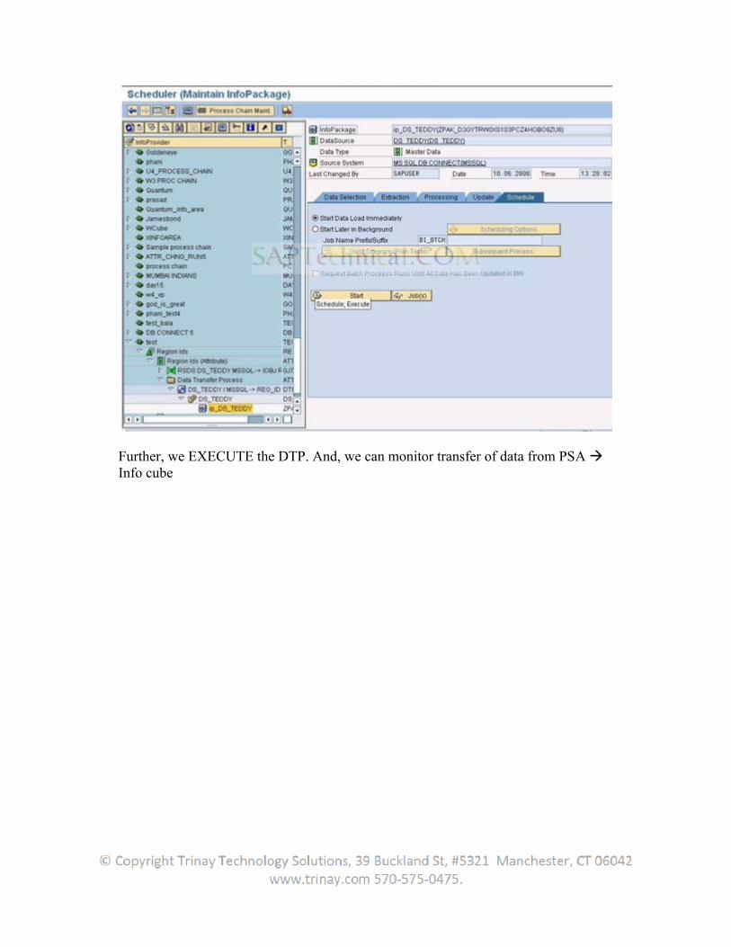
Further, we EXECUTE the DTP. And, we can monitor transfer of data from PSA Info cube
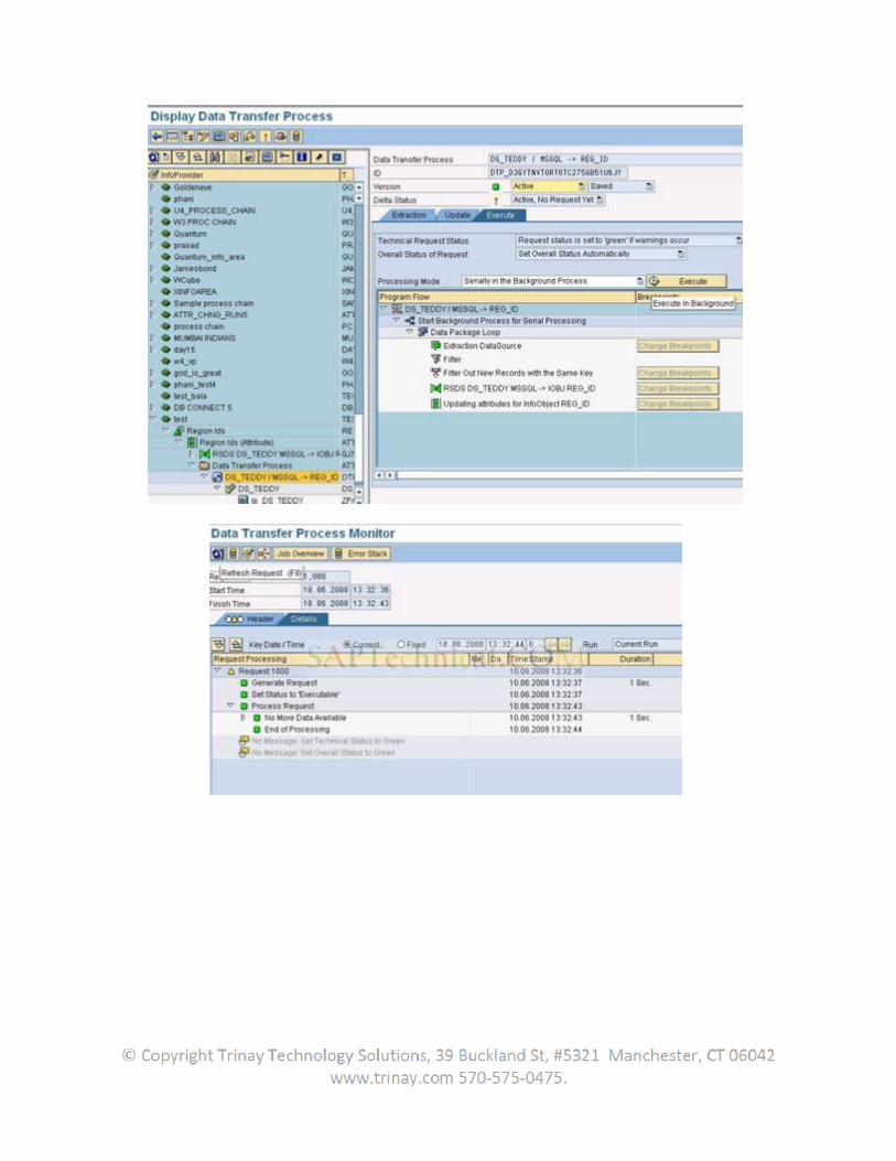
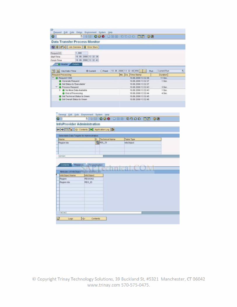
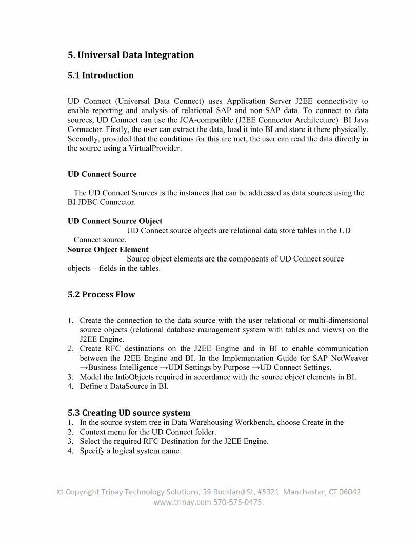
5. Universal Data Integration
5.1 Introduction
UD Connect (Universal Data Connect) uses Application Server J2EE connectivity to enable reporting and analysis of relational SAP and non-SAP data. To connect to data sources, UD Connect can use the JCA-compatible (J2EE Connector Architecture) BI Java Connector. Firstly, the user can extract the data, load it into BI and store it there physically. Secondly, provided that the conditions for this are met, the user can read the data directly in the source using a VirtualProvider.
UD Connect Source
The UD Connect Sources is the instances that can be addressed as data sources using the BI JDBC Connector.
UD Connect Source Object UD Connect source objects are relational data store tables in the UD
Connect source.Source Object Element Source object elements are the components of UD Connect sourceobjects – fields in the tables.
5.2 Process Flow
1. Create the connection to the data source with the user relational or multi-dimensional source objects (relational database management system with tables and views) on the J2EE Engine.
2. Create RFC destinations on the J2EE Engine and in BI to enable communication between the J2EE Engine and BI. In the Implementation Guide for SAP NetWeaver →Business Intelligence →UDI Settings by Purpose →UD Connect Settings.
3. Model the InfoObjects required in accordance with the source object elements in BI. 4. Define a DataSource in BI.
5.3 Creating UD source system1. In the source system tree in Data Warehousing Workbench, choose Create in the2. Context menu for the UD Connect folder.3. Select the required RFC Destination for the J2EE Engine.4. Specify a logical system name.
5. Select JDBC as the connector type.6. Select the name of the connector.7. Specify the name of the source system if it has not already been derived from the8. Logical system name.9. Choose Continue.
5.4 Creating a DataSource for UD Connect To transfer data from UD Connect sources to BI, the metadata
(information about the source object and source object elements) must be create in BI in the form of a DataSource.
1. Select the application component where the user want to create the DataSource andchoose Create DataSource.
2. On the next screen, enter a technical name for the DataSource, select the type of DataSource and choose Copy. The DataSource maintenance screen appears.
3. Select the General tab.
a) Enter descriptions for the DataSource (short, medium, long).b) If required, specify whether the DataSource is initial non-cumulative and might produce duplicate data records in one request.
4. Select the Extraction tab.a) Define the delta process for the DataSource.b) Specify whether the user want the DataSource to support direct access to data.c) UD Connect does not support real-time data acquisition.d) The system displays Universal Data Connect (Binary Transfer) as the adapter for the DataSource. Choose Properties if the user want to display the general adapter properties.e) Select the UD Connect source object.
A connection to the UD Connect source is established. All source objects available in the selected UD Connect source can be selected using input help.
5. Select the Proposal tab.The system displays the elements of the source object (for JDBC it is these fields) andcreates a mapping proposal for the DataSource fields. The mapping proposal is basedon the similarity of the names of the source object element and DataSource field and thecompatibility of the respective data types. Note that source object elements can have a maximum of 90 characters. Both upper and lower case are supported.
a) Check the mapping and change the proposed mapping as required. Assign the non-assigned source object elements to free DataSource fields. The user cannot
map elements to fields if the types are incompatible. If this happens, the system displays an error message.
b) Choose Copy to Field List to select the fields that the user want to transfer to the field list for the DataSource. All fields are selected by default.
6. Define the Fields tab.
Here, the user can edit the fields that the user transferred to the field list of the DataSource from the Proposal tab. If the system detects changes between the proposal and the field list when switch from the Proposal tab to the Fields tab, a dialog box is displayed where the user can specify whether the user want to copy changes from the proposal to the field list.
a) Under Transfer, specify the decision-relevant DataSource fields that the user wants to be available for extraction and transferred to BI.b) If required, change the values for the key fields of the source. These fields are
generated as a secondary index in the PSA. This is important in ensuring good performance for data transfer process selections, in particular with semantic grouping
c) If required, change the data type for a field.d) Specify whether the source provides the data in the internal or external format.e) If the user chooses an External Format, ensure that the output length of the
field (external length) is correct. Change the entries if required.f) If required, specify a conversion routine that converts data from an external
format to an internal format.g) Select the fields that the user wants to be able to set selection criteria for when
scheduling a data request using an InfoPackage. Data for this type of field is transferred in accordance with the selection criteria specified in the InfoPackage.
h) Choose the selection options (such as EQ, BT) that the user wants to be available for selection in the InfoPackage.
i) Under Field Type, specify whether the data to be selected is language-dependent or time-dependent, as required.
If the user did not transfer the field list from a proposal, the user can define the fields of the DataSource directly. Choose Insert Row and enter a field name. The user can specify InfoObjects in order to define the DataSource fields. Under Template InfoObject, specify InfoObjects for the fields of the DataSource. This allows the user to transfer the technical properties of the InfoObjects to the DataSource field.
Entering InfoObjects here does not equate to assigning them to DataSource fields. Assignments are made in the transformation. When the user define the transformation, the system proposes the InfoObjects the user entered here as InfoObjects that the user might want to assign to a field
7. Check, save and activate the DataSource8. Select the Preview tab.
If the user selects Read Preview Data, the number of data records the user specified in the user field selection is displayed in a preview. This function allows the user to check whether the data formats and data are correct.
5.5 Using Relational UD Connect Sources (JDBC)
5.5.1 Aggregated Reading and Quantity Restriction
In order to keep the data mass that is generated during UD Connect access to a JDBC datasource as small as possible, each select statement generated by the JDBC adapter receivesa group by clause that uses all recognized characteristics. The recognized key figures areaggregated. What is recognized as a key figure or characteristic and which methods areused for aggregation depends on the properties of the associated InfoObjects modeled inSAP BW for this access.The amount of extracted data is not restricted. To prevent exceeding the storage limitationsof the J2EE server, packages with around 6,000 records are transferred to the calling ABAPmodule.
5.5.2 Use of Multiple Database Objects as UD Connect Source Object
Currently only one database object (table, view) can be used for a UD Connect Source. TheJDBC scenario does not support joins. However, if multiple objects are used in the form of a join, a database view should be created that provides this join and this object is to be usedas a UD Connect source object. The view offers more benefits: The database user selected from SAP BW for access is only permitted to access
these objects. Using the view, the user can run type conversions that cannot be made by the
adapter (generation of the ABAP data type DATS, TIMS etc.)
5.6 BI JDBC Connector
Sun's JDBC (Java Database Connectivity) is the standard Java API for RelationalDatabase Management Systems (RDBMS). The BI JDBC Connector allows the user to connectapplications built with the BI Java SDK to over 170 JDBC drivers, supporting data sourcessuch as Teradata, Oracle, Microsoft SQL Server, Microsoft Access, DB2, Microsoft Excel,and text files such as CSV. This connector is fully compliant with the J2EE Connector
Architecture (JCA).The user can also use the BI JDBC Connector to make these data sources available in SAP BI systems using UD Connect. The user can also create systems in the portal that are based on this connector.The connector adds the following functionality to existing JDBC drivers:• Standardized connection management that is integrated into user management in the portal• A standardized metadata service, provided by the implementation of JMI capabilitiesbased on CWM• A query model independent of the SQL dialect in the underlying data sourceThe JDBC Connector implements the BI Java SDK's IBIRelational interface.
5.6.1 Deploy the user data source’s JDBC driver to the server:
1. Start the Visual Administrator.2. On the Cluster tab, select Server x → Services → JDBC Connector.3. In the right frame, select the Drivers node on the Runtime tab.4. From the icon bar, choose Create New Driver or Data source.5. In the DB Driver field in the Add Driver dialog box, enter a name for the user
JDBC driver.6. Navigate to the user JDBC driver's JAR file and select it.7. To select additional JAR files, select Yes when prompted, and when finished,8. Select No.
5.6.2 Configuring BI Java Connector
To prepare a data source for use with the BI Java SDK or with UD Connect, the user first need to configure the properties in BI Java Connector used to connect to the data source. The user does this in SAP NetWeaver Application Server’s Visual Administrator.
In the service Connector Container, configure a reference to the JDBC driver of the userdata source. This can be done by performing the following steps:
1. Select the BI JDBC Connector in the Connectors tree.2. Choose the Resource Adapter tab.3. In the Loader Reference box, choose Add to add a reference to the user JDBC
driver.4. Enter library :<jdbc driver name> and choose OK.5. The <jdbc driver name> is the name the user entered for the user driver when the
user loaded it (see Prerequisites in BI JDBC Connector).6. Save the settings.
5.6.2.1 Testing the Connections
After the user has configured the BI Java Connector, the user can perform a rough installation check by displaying the page for the connector in the userserver. Perform the tests for the connector by visiting the URLs
5.6.2.2 JNDI Names
When creating applications with the BI Java SDK, refer to a connector by its JNDI name: The BI JDBC Connector has the JNDI name SDK_JDBC.
5.6.2.3 Cloning the Connections
The user can clone an existing connection by using the Clone button in the toolbar.
5.6.3 Connector Properties
Refer to the table below for the required and optional properties to configure for the user connector: BI JDBC Connector Properties
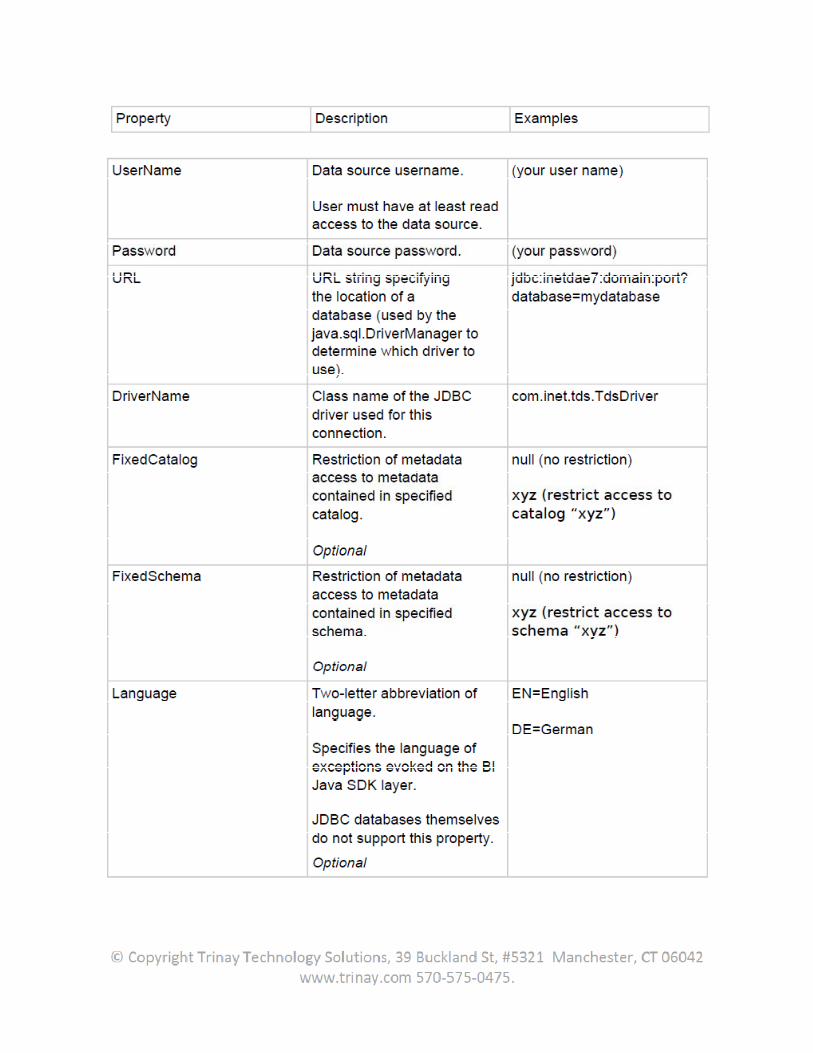
5.7 BI XMLA Connector
Microsoft's XMLA (XML for Analysis) facilitates Web services-based, platform-independent access to OLAP providers. The BI XMLA Connector enables the exchange of analytical data between a client application and a data provider working over the Web, using SOAP based XML communication API.
The XMLA Connector sends commands to an XMLAcompliant OLAP data source in order to retrieve the schema rowsets and obtain a result set. The BI XMLA Connector allows the user to connect applications built with the BI Java SDK to data sources such as Microsoft Analysis Services, Hyperion, MicroStrategy, MIS, and BW 3.x. This connector is fully compliant with the J2EE Connector Architecture (JCA).The user can also use the BI XMLA Connector to make these data sources available in SAP BI Systems via UD Connect, or the user can create systems in the portal based on this connector. The BI XMLA Connector implements the BI Java SDK's IBIOlap interface.
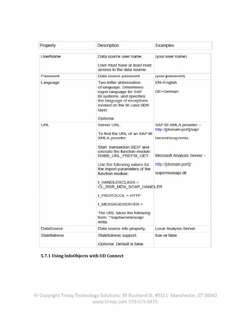
5.7.1 Using InfoObjects with UD Connect
When modeling InfoObjects in BI, note that the InfoObjects have to correspond to the source object elements with regard to the type description and length description. For more information about data type compatibility,
.The following restrictions apply when using InfoObjects:• Alpha conversion is not supported• The use of conversion routines is not supported• Upper and lower case must be enabled
These InfoObject settings are checked when they are generated.
5.7.2 Using SAP Namespace for Generated Objects
The program-technical objects that are generated during generation of a DataSource for UD connect can be created in transportable or local format. Transportable means that the generated objects can be transferred to another SAP BW system using the correction and transport system. The transportability of an object depends on, among other things, in which namespace it is created.
The delivery status allows for the generation of transportable objects in the SAP namespace. If this appears to be too laborious (see the dependencies listed below), there is also the option of switching to generation of local objects. To do this, the user run the RSSDK_LOCALIZE_OBJECTS report in the ABAP editor (transaction: SE 38). Then the system switches to local generation. The objects generated afterward are not transportable. If the report is executed again, the generation is changed back to transportable. The status of already generated objects does not change. All new objects are created as transportable. If the user need to work with transportable objects, the user should be aware of the following dependencies:
System changeability
These objects can only be generated in systems whose system changeability permits this. In general, these are development systems, because productive systems block system changeability for security reasons.• If a classic SAP system landscape of this type exists, then the objects are created in the development system and assigned to package RSSDK_EXT. This package is especially designated for these objects. The objects are also added to a transport request that the user create or that already exists. After the transport request is finished, it is used to transfer the infrastructure into the productive environment.
Key
Because the generated objects are ABAP development objects, the user must be authorized as a developer. A developer key must be procured and entered.
Generation requires the customer-specific installation number and can be generated online. The system administrator knows this procedure and should be included in the procurement. The key has to be procured and entered exactly once per user and system. Because the generated objects were created in the SAP namespace, an object key is required.
Like the developer key, this is customer specific and can also be procured online. The key is to be entered exactly once per object and system. Afterwards, the object is released for further changes as well. Further efforts are not required if there are repeated changes to the field list or similar.
6. XML Integration
6.1 Introduction
SAP’s Business Connector (SAP BC) is a business integration tool to allow SAP Customers the ability to communicate with other SAP customers or SAP marketplaces. The Business Connector allows integration with R/3 via open and non-proprietary technology. This middleware component uses the Internet as communication platform and XML/HTML as data format thus seamlessly integrating different IT architectures with R/3.
SAP BC integrates RFC server and the client and provides an XML layer over R/3 functionality. That is, it comes with an XML automation that converts SAP’s RFC format into XML and supports both synchronous RFC and asynchronous RFC protocols such that there is no requirement of SAP R/3 automation at the receiving end. Also, SAP BC has a built in integration support for SAP’s specification of IDOC-XML and RFC-XML standards. Hence, whenever dealing with the messages conforming to the same standards it supports the integration.
6.2 Benefits of XML Integration
End-to-End Web Business Processes Open Business Document Exchange over the Internet XML Solutions for SAP services
6.2.1 End-to-End Web Business Processes
Internet bridges the gap between different businesses, systems and users and facilitates them do business via web. SAP BC makes this communication easier by its XML conversions. Through its integration with XML it enables the exchange of structured business documents over the Internet by providing common standard for different applications and IT systems to communicate and exchange business data.
6.2.2 Open Business Document Exchange over the Internet
SAP Business Connector uses hypertext transfer protocol (HTTP) to exchange XML-based documents over the Internet. This makes the process of data transfer a lot easier by providing a common structure for all business documents. It also ensures secure exchange of documents with the help of its Security Socket Layer (SSL) technology and allows implementation of maps, branches and loops without any coding by using developer tool. In addition, SAP BC provides openness and flexibility to comply with emerging business semantics that continuously keep on changing.
6.2.3 XML Solutions for SAP services
SAP BC makes all mySAP.com solutions accessible via XML based business documents. It supports all major existing interfaces that are provided by SAP with the help of XML-based Interface Repository (IFR) and empowers SAP customers to benefit from SAP functionality over the Internet. This IFR gives the option for downloading XML schemas for operational use and provides a uniform XML interface representation despite different implementation technologies such as RFC, IDOC and BAPI. Also with SAP BC, XML messages are translated into corresponding SAP internal call whenever required and converted back into XML format when received from SAP system enhancing the existing programming model for distributed applications formed by ALE. In addition, SAP BC extends business scenarios across firewalls enabling secure flow of business documents without requiring changes to establish security infrastructures.
6.3 Business Integration with XML
Business processes are increasingly characterized by structures operating between companies. Companies no longer act in isolation: instead, they are integrated into geographically distributed production networks, pursuing the production process in cooperation with other firms. This means that exchanging data quickly and securely between applications and systems is an increasingly important requirement.
XML acts as a uniform standard for exchanging business data, through which heterogeneous applications can communicate with one another over uniform interfaces and in a language, which everyone involved, can understand. With XML, simple and complex structures can be presented at any data level and for any category of data.
Non-SAP applications can now be used by SAP customers owing to XML compliance. For example, using a company’s services in the cyber marketspace allows the customer data to be received and directly stored on vendor system as both are using data formatted in XML. These third-party systems using the XML standard data format are increasing rapidly. A customer using SAP can use a range of add-on products and services to their existing applications.
XML integration is also easier than using proprietary communication formats like SAP's BAPIs and RFCs. This has found widespread customer acceptance as it reduces integration and maintenance cost of interface integration during the implementation of non-SAP systems. Furthermore, customers can now exchange data with XML standard by using the Internet infrastructure through a much-more user-friendly Web Browser.
An XML environment of data exchange over the Internet via security protocols such as HTTP, HTTPS and FTP fully supports collaborative business scenarios, increasingly common in an integrated world. XML formatting and message handling with the help of the SAP Business Connector allows customers to use an industry-wide accepted format for data exchange between the SAP system and partner systems including historically grown proprietary systems.
The ability to integrate and analyze business data across applications, structured and unstructured information, and heterogeneous systems extends the traditional business environment and provides users with a complete view of the business.
6.3.1 Incorporating XML Standards
Various XML standards are supported by SAP. It presents data according to an SAP specification either in IDoc-XML or BAPI-XML, the SAP XML extensions for IDocs and BAPIs. It uses preprepared representations of the SAP interfaces to XML Commerce Business Language (xCBL) messages to facilitate communication with the MarketSet marketplaces.
Messages are stored in a generic envelope. This envelope contains metadata that controls, among other things, the routing of the messages. SAP supports two different standards for these envelopes - Microsoft BizTalk and a format similar to Simple Object Access Protocol (SOAP). Packaging SAP BAPIs in a standard envelope offers several advantages, including direct processing of messages by external applications and a uniform system of error handling.
6.3.2 SAP’s Internet Business Framework
SAP's Internet Business Framework (IBF) attempts to address business collaboration issues by enabling integration with Internet technologies at the user, component, and business-process levels:
User integration is achieved by providing a single point of Web-based access to the workplace (that is, local and company wide systems) and the marketplace (that is, systems across a number of companies).
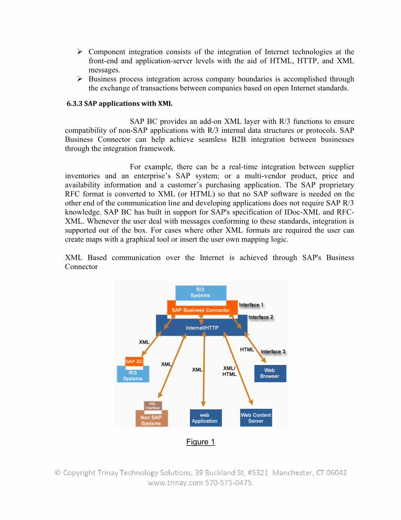
Component integration consists of the integration of Internet technologies at the front-end and application-server levels with the aid of HTML, HTTP, and XML messages.
Business process integration across company boundaries is accomplished through the exchange of transactions between companies based on open Internet standards.
6.3.3 SAP applications with XML
SAP BC provides an add-on XML layer with R/3 functions to ensure compatibility of non-SAP applications with R/3 internal data structures or protocols. SAP Business Connector can help achieve seamless B2B integration between businesses through the integration framework.
For example, there can be a real-time integration between supplier inventories and an enterprise’s SAP system; or a multi-vendor product, price and availability information and a customer’s purchasing application. The SAP proprietary RFC format is converted to XML (or HTML) so that no SAP software is needed on the other end of the communication line and developing applications does not require SAP R/3 knowledge. SAP BC has built in support for SAP's specification of IDoc-XML and RFC-XML. Whenever the user deal with messages conforming to these standards, integration is supported out of the box. For cases where other XML formats are required the user can create maps with a graphical tool or insert the user own mapping logic.
XML Based communication over the Internet is achieved through SAP's Business Connector
Figure 1
6.3.4 Factors leading to emergence of XML-enabled SAP solutions
6.3.4.1 Changing Business Standards and their adoption
Mapping of SAP business documents and the XML-based business documents can be easily done with SAP Business Connector. The flexible architecture of the SAP Business Connector makes it easy to add specific schemas and interfaces To comply with business documents standards, the Business Connector provides for automated generation of server and client side codes thus solving the interconnectivity problem by enabling uniform transactions among customers.
A business model based on these standards allows companies to move towards becoming make-to-order businesses replete with all the marketing, sales, distribution, manufacturing and other logistic-driven operational cost savings.
6.3.4.2 Internet Security Standards
The effectiveness of E-commerce is premised on a secure exchange of information. The SAP business connector provides security essential to an online business transaction. Business partners can be authenticated and business documents can be securely exchanged. The SAP Business Connector supports the well-established standard encryption technology Secure Socket Layer (SSL) for secure document exchange. Digital signature will ensure authentication of crucial data.
SAP communication is achieved through Idocs, BAPIs, and RFCs. These documents must be made compliant with Internet. This conversion is achieved using the Business Connector. Business Connector converts SAP documents into XML so that they can be exchanged using Internet protocols.
6.4 Web-based business solutions
The SAP Business Connector allows businesses to effectively use intra and inter-enterprise information. For example-companies can use the SAP Business Connector to retrieve catalog information from a suppliers’ Web site and to integrate the information with internal processes - in real time.
6.4.1 Components of Business Connector
A business connector constitutes a Server and an Integrator. The Integrator can be used to add any additional functionality to the Server.
SAP Business connector in association with a third party XML enabled software product can only be used for collaborative business-to-business scenarios
such as transmitting catalog information, managing purchase orders and availability to promise checks, acknowledging purchase orders, and handling invoices.
The requirements for XML interface certification for SAP's complementary software include:
Use of HTTP and HTTPS protocols with the SAP Business Connector Customization for a specific Business Application Sending and receiving the communication objects (i.e. Idocs, BAPIs or RFCs)
6.5 How to Customize Business Connector (BC)
1. Start the Business Connector by calling <BC_dir>/bin/server.bat. If the user wants to have a debug output, enter server.bat –debug <debuglevel> –log <filename>. Debuglevelcannot be > 10.
2. Open the Business Connector administration screen into a web browser window. Enter the user Username and corresponding password.
6.5.1 Add New Users to BC
3. If the user want to transmit data from an SAP system to the BC, the user need to have the same user in both systems. For creating users in the BC click Security > Users and Groups > Add and Remove Users.
4. Enter the desired SAP User, assign the corresponding Password and click Create Users. This creates a User. Mark the just created User in the Groups box section and make sure that the ‘Select Group’ ="Administrators". Now, add the User into the Administrators group by clicking (below the right selection box). Click Save Changes to save the settings.
6.5.2 Add SAP Systems
5. All the proposed SAP system(s) should be added within the Business Connector. To achieve this, click Adapters > SAP which opens a new window. In the new window click SAP > SAP Servers > Add SAP Server.
6. Enter the necessary information for the SAP server (System, Login Defaults, Server Logon, and Load Balancing. "Save" (as illustrated in screen 1).
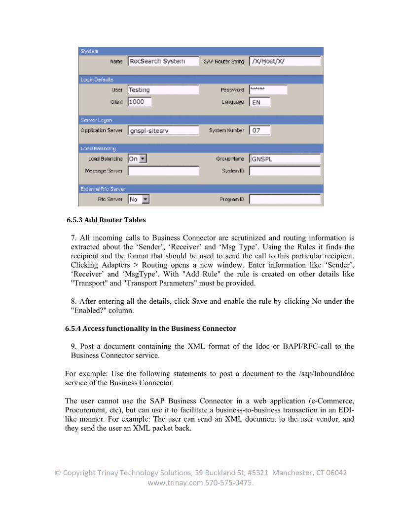
6.5.3 Add Router Tables
7. All incoming calls to Business Connector are scrutinized and routing information is extracted about the ‘Sender’, ‘Receiver’ and ‘Msg Type’. Using the Rules it finds the recipient and the format that should be used to send the call to this particular recipient. Clicking Adapters > Routing opens a new window. Enter information like ‘Sender’, ‘Receiver’ and ‘MsgType’. With "Add Rule" the rule is created on other details like "Transport" and "Transport Parameters" must be provided.
8. After entering all the details, click Save and enable the rule by clicking No under the "Enabled?" column.
6.5.4 Access functionality in the Business Connector
9. Post a document containing the XML format of the Idoc or BAPI/RFC-call to the Business Connector service.
For example: Use the following statements to post a document to the /sap/InboundIdoc service of the Business Connector.
The user cannot use the SAP Business Connector in a web application (e-Commerce, Procurement, etc), but can use it to facilitate a business-to-business transaction in an EDI-like manner. For example: The user can send an XML document to the user vendor, and they send the user an XML packet back.
7. Data Mart Interface
7.1 Introduction
The data mart interface makes it possible to update data from one InfoProvider to another. Data exchange of multiple BI Systems: the data-delivering system is referred to as the Source B; the data-receiving system as the Target BI. The individual BI systems arranged in this way are called data marts. The InfoProviders of the source BI are used as sources of data here. Data exchange between BI systems and other SAP systems.
Data marts can be used in different ways: They save a subset of the data of a Data Warehouse in another database, possibly
even in a different location. They are smaller units of a Data Warehouse. They are stored as intentionally redundant segments of the (logical, global) overall
system (Data Warehouse).
A BI system defines itself as the source system for another BI system by:
Providing metadata Providing transaction data and master data
An export DataSource is needed to transfer data from a source BI into a target BI. Export DataSources for InfoCubes and DataStore objects contain all the characteristics and key figures of the InfoProvider. Export DataSources for master data contain the metadata for all attributes, texts, and hierarchies for an InfoObject.
7.2 Special Features
Changes to the metadata of the source system can only be added to the export DataSources by regenerating the export DataSources.
The Delete function is not supported at this time. The user can only generate an export DataSource from an InfoCube if:
The InfoCube is activated The name of the InfoCube is at least one character shorter than the
maximum length of a name, since the DataSource name is made up of the InfoCube name and a prefix.
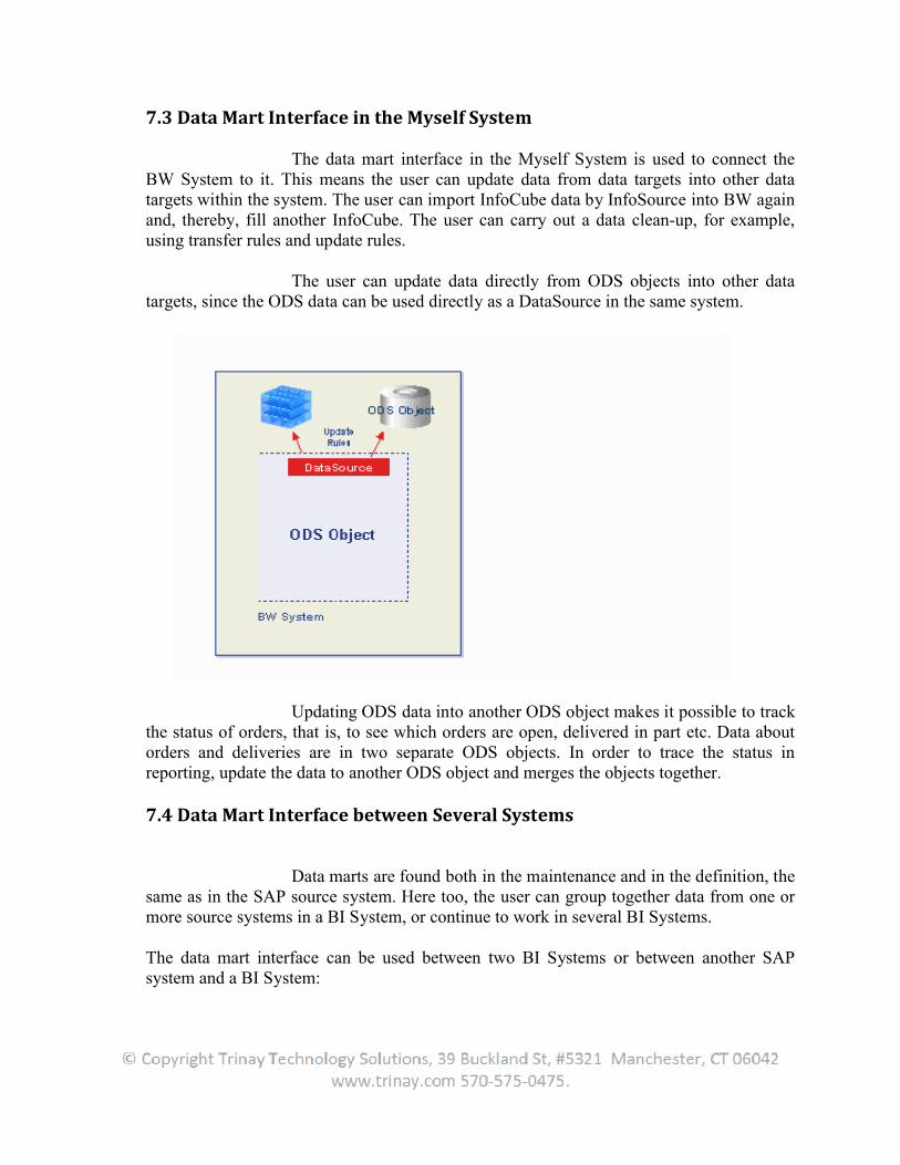
7.3 Data Mart Interface in the Myself System
The data mart interface in the Myself System is used toBW System to it. This means targets within the system. The userand, thereby, fill another InfoCube. using transfer rules and update rules.
The usertargets, since the ODS data can be used directly as a DataSource in the same system.
Updating ODS data into another ODS objthe status of orders, that is, to see which orders are open, delivered in part etc. Data about orders and deliveries are in two separate ODS objects. In order to trace the status in reporting, update the data to another ODS o
7.4 Data Mart Interface
Data marts are found both in the maintenance and in the definition, the same as in the SAP source system. Here too, more source systems in a BI System, or continue to work in several BI Systems.
The data mart interface can be used between two BI Systems or between another SAP system and a BI System:
Data Mart Interface in the Myself System
The data mart interface in the Myself System is used to. This means the user can update data from data targets into other data
The user can import InfoCube data by InfoSource into BW again and, thereby, fill another InfoCube. The user can carry out a data clean-using transfer rules and update rules.
The user can update data directly from ODS objects into other data targets, since the ODS data can be used directly as a DataSource in the same system.
Updating ODS data into another ODS object makes it possible to track the status of orders, that is, to see which orders are open, delivered in part etc. Data about orders and deliveries are in two separate ODS objects. In order to trace the status in
update the data to another ODS object and merges the objects together.
Data Mart Interface between Several Systems
Data marts are found both in the maintenance and in the definition, the same as in the SAP source system. Here too, the user can group together data from one or
ource systems in a BI System, or continue to work in several BI Systems.
The data mart interface can be used between two BI Systems or between another SAP
The data mart interface in the Myself System is used to connect the can update data from data targets into other data
can import InfoCube data by InfoSource into BW again -up, for example,
can update data directly from ODS objects into other data targets, since the ODS data can be used directly as a DataSource in the same system.
ect makes it possible to track the status of orders, that is, to see which orders are open, delivered in part etc. Data about orders and deliveries are in two separate ODS objects. In order to trace the status in
the objects together.
Data marts are found both in the maintenance and in the definition, the can group together data from one or
ource systems in a BI System, or continue to work in several BI Systems.
The data mart interface can be used between two BI Systems or between another SAP
To enable large amounts of data to be processed To increase the respective speeds of data transfer, logging and analysis. To achieve improved concision and maintenance of the individual Data
Warehouses. To enable data separation relating to the task area, on the one hand, and to be able
to perform analyses of the state of the entire dataset on the other. To make it possible to have fewer complexities when constructing and
implementing a Data Warehouse. To construct hub and spoke scenarios in which a BI System stands in the middle
and the data from distributed systems runs together and is standardized.
7.4.1 Architectures
The functions can produce different architectures in a Data Warehouse landscape.
Replication Architecture Aggregation Architecture
7.4.1.1 Replicating Architecture
If the user selects this architecture, the data for a BI server is available as source data and can be updated in further target BI Systems.
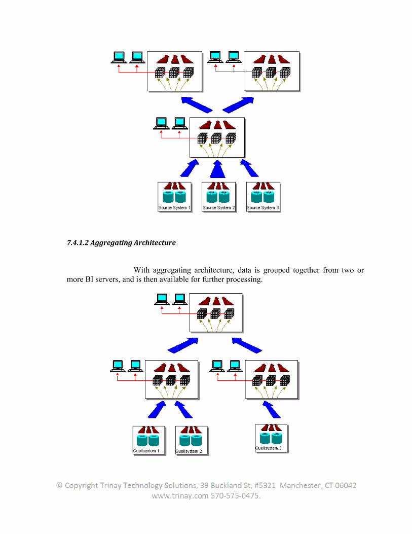
7.4.1.2 Aggregating Architecture
With aggregating architecture, data is grouped together from two or more BI servers, and is then available for further processing.
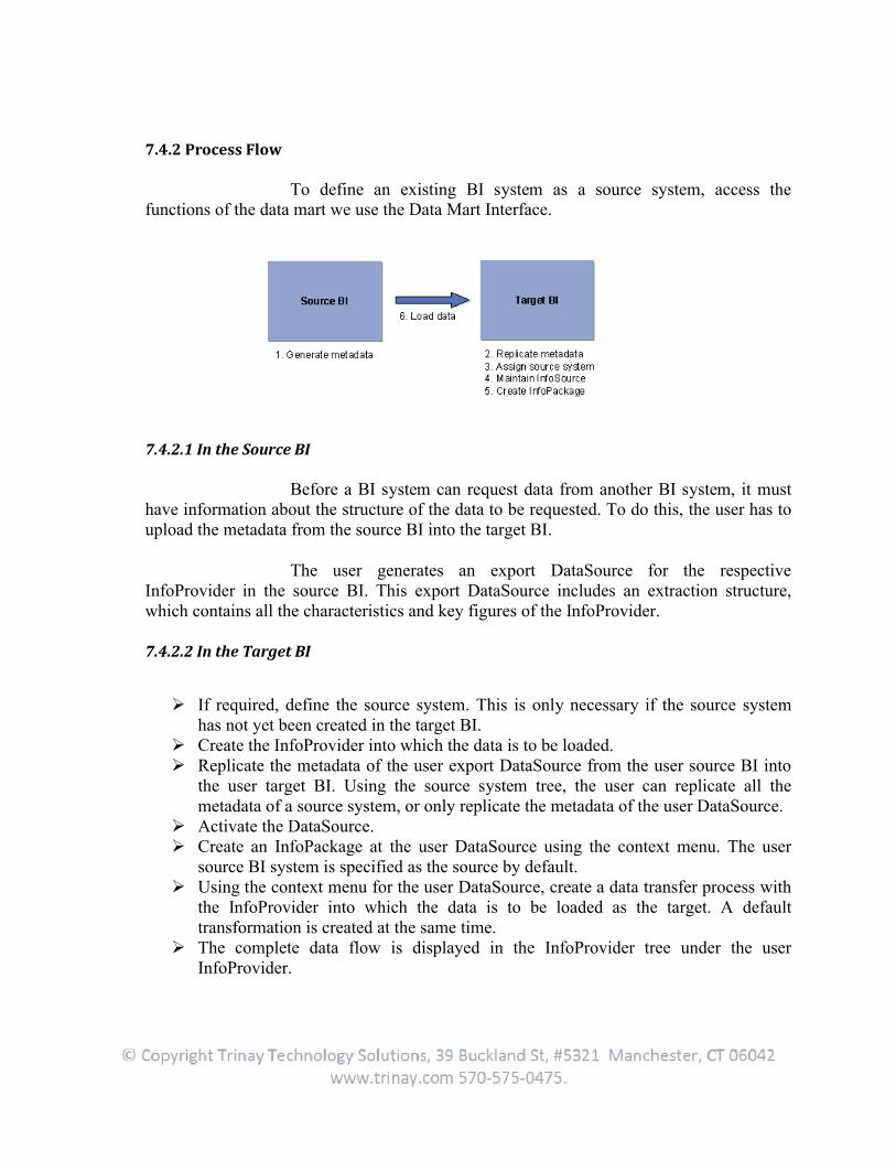
7.4.2 Process Flow
To define an existing BI system as a source system, access the functions of the data mart we use the Data Mart Interface.
7.4.2.1 In the Source BI
Before a BI system can request data from another BI system, it must have information about the structure of the data to be requested. To do this, the user has to upload the metadata from the source BI into the target BI.
The user generates an export DataSource for the respective InfoProvider in the source BI. This export DataSource includes an extraction structure, which contains all the characteristics and key figures of the InfoProvider.
7.4.2.2 In the Target BI
If required, define the source system. This is only necessary if the source system has not yet been created in the target BI.
Create the InfoProvider into which the data is to be loaded. Replicate the metadata of the user export DataSource from the user source BI into
the user target BI. Using the source system tree, the user can replicate all the metadata of a source system, or only replicate the metadata of the user DataSource.
Activate the DataSource. Create an InfoPackage at the user DataSource using the context menu. The user
source BI system is specified as the source by default. Using the context menu for the user DataSource, create a data transfer process with
the InfoProvider into which the data is to be loaded as the target. A default transformation is created at the same time.
The complete data flow is displayed in the InfoProvider tree under the userInfoProvider.
Schedule the InfoPackage and the data transfer process. We recommend that the user always use process chains for loading processes.
7.4.3 Generating Export DataSources for InfoProviders
The export DataSource is needed to transfer data from a source BI system into a target BI system. The user can use the selected InfoProvider as a DataSource for another BI system.
1. In the Data Warehousing Workbench in the BI source system, choose Modelingand select the InfoProvider tree.
2. Generate the export DataSource using the context menu of the user InfoProvider. To do this, choose Additional Functions Generate Export DataSource.
The technical name of the export DataSource is made up of the number 8 together with the name of the InfoProvider. Technical name of an InfoCube: COPA.Technical name of the export DataSource: 8COPA
7.4.4 Generating Master Data Export DataSources
The export DataSource is needed to transfer data from a source BI system into a target BI system. The user can generate an export DataSource for master data, and thus for individual InfoObjects. By doing this, all the metadata is created that is required to extract master data (all attributes, texts, and hierarchies) from an InfoObject.
1. Select the InfoObject tree in the Data Warehousing Workbench in the source BI system.
2. Generate the export DataSource from the context menu of the user InfoObject. To do this, choose Additional Functions Generate Export DataSource.
The technical name of the export DataSource is
8******M for attributes (M stands for master data)8******T for texts8******H for hierarchies.
(The asterisks (*) stand for the source InfoObject).
When the user create an InfoObject or a master data InfoSource in the source BI system, the user must therefore make sure that the length of the technical name of each object is no longer than 28 characters.
7.4.5 Transactional Data Transfer Using the Data Mart Interface
The data transfer is the same as the data transfer in an SAP system. The system reads the data, taking into account the specified dimension-specific selections, from the fact tables of the delivering BI system.
7.4.5.1 Delta Process
Using the data mart interface, the user can transfer data by full upload as well as by delta requests. A distinction is made between InfoCubes and DataStore objects.
The InfoCube that is used as an export DataSource is first initialized, meaning that the current status is transferred into the target BI system. When the next upload is performed, only those requests are transferred that have come in since initialization.Different target systems can also be filled like this. Only those requests are transferred that have been rolled up successfully in the aggregates. If no aggregates are used, only those requests are transferred that are set to Qualitative OK in the InfoCube administration.
For DataStore objects, the requests in the change log of the DataStore object are used as the basis for determining the delta. Only the change log requests that have arisen from reactivating the DataStore object data are transferred.
7.4.5.2 Restriction
It is possible to only make one selection for each target system for the delta. The user first makes a selection using cost center 1 and load deltas for this selection. Later on, the user also decides to load a delta for cost center 2 in parallel to the cost center 1 delta. The delta can only be fully requested for both cost centers, meaning that it is then impossible to separately execute deltas for the different selections
7.4.6 Transferring Texts and Hierarchies for the Data Mart Interface
The transfer of master data is scheduled in the Scheduler. It corresponds to the data transfer for an R/3 System. If the user wants to load texts or hierarchies using the Scheduler, the user must first create them in the source system.
When the user load hierarchies, the user get to the available hierarchiesfrom the Hierarchy Selection tab page by using the pushbutton Available Hierarchies in OLTP. Select the user hierarchy and schedule the loading.
7. Virtual InfoCubes
7.1 Introduction
They only store data virtually, not physically and are made available to Reporting as Info-Providers. Virtual remote cube can be used to 'act like an infocube, feel like an infocube, but is not an infocube', The user can create this virtual infoprovider, having the same structure similar to infocube, with dimensions, characteristics and key figures. But the actual generation of data for this cube, is, well depends on the user making.
The user can choose to create a virtual provider with a 'direct access' to R/3. This means that upon viewing the data in this virtual provider, a remote function call is called direct to R/3 to get the values on the fly. The user can also choose to get value from a function module of the user calling, so the implementation details are really up to the user.
7.2 Create Virtual Infocube
In BI7, just right click on any infoarea, and choose create 'virtual provider'. For direct access, the user chooses Virtual Provider with 'direct access'. There's an option to use the old R/3 infosource. What this means is that the user can create an infosource with transfer rules and such, and when the user create the virtual infoprovider, it will use the structure in the infosource automatically and the flow of data is automatically link R/3 with the transfer rules and the virtual infoprovider. Note that no update rules exist with this kind of setup.
But in Bi7, the user have a more flexible approach in that the user can create a transformation to configure the 'transfer logic' of the user virtual infoprovider, along with start routine, end routine or any other transformation technique visible with using a transformation rule.
But using BI7 setup, the user need to create a sort of 'pseudo' DTP, which doesn't actually do anything, meaning the user do not 'execute' it to start a data transfer. After all is done, the user need to right click on the virtual infoprovider and choose 'Activate Direct Access'. If the user uses Infosource, go to the Infosource tab, and choose the infosource. If the user is using BI7 setup, choose the DTP related to the transformation and save it.
7.3 Different Types
A distinction is made between the following types:
SAP RemoteCube RemoteCube Virtual InfoCube with Services
7.3.1 SAP RemoteCube
An SAP RemoteCube is a RemoteCube that allows the definition of queries with direct access to transaction data in other SAP systems.
Use SAP RemoteCubes if:
The user need very up The user only access a small amount of data from time to time Only a few users execute queries simultaneously on the database.
Do not use SAP RemoteCubes if:
The user request a large amount of data in the first query navigation step, and no appropriate aggregates are available in the source system
A lot of users execute queries simultaneously The user frequently access the same data
7.3.1.1 Creating a SAP RemoteCube
The SAP RemoteCube can be used in reporting in cases where it does not differ from other InfoProviders.
1. Choose the InfoSource tree or InfoProvider tree in the Administrator Workbench under Modeling. 2. In the context menu, choose 3. Select SAP RemoteCube 4. The user can define if a unique source system is assigned to the InfoCube using an indicator. Otherwise the usercase the characteristic (0LOGSYS) is added to the InfoCube definition. 5. In the next screen if necessary before activation. 6. The user can then assign source systems to the SAP RemoteCube. To do this, choose Assign Source Systemdialog box that follows, choose one or several source systems and select Assignments. The source transported.
Virtual InfoCube with Services
An SAP RemoteCube is a RemoteCube that allows the definition of queries with direct access to transaction data in other SAP systems.
need very up-to-date data from an SAP source systemonly access a small amount of data from time to time
Only a few users execute queries simultaneously on the database.
use SAP RemoteCubes if:
request a large amount of data in the first query navigation step, and no appropriate aggregates are available in the source systemA lot of users execute queries simultaneously
frequently access the same data
Creating a SAP RemoteCube
The SAP RemoteCube can be used in reporting in cases where it does not differ from other
Choose the InfoSource tree or InfoProvider tree in the Administrator Workbench
In the context menu, choose Create InfoCube.SAP RemoteCube as InfoCube type and enter the user InfoSource.
can define if a unique source system is assigned to the InfoCube using the user must select the source system in the relevant query. In this
case the characteristic (0LOGSYS) is added to the InfoCube definition.In the next screen the user can check the defined SAP RemoteCube and adjust it
if necessary before activation.can then assign source systems to the SAP RemoteCube. To do this,
Assign Source System from the context menu in the user SAP RemoteCube. In the dialog box that follows, choose one or several source systems and select
. The source system assignments are local to the system and are not
An SAP RemoteCube is a RemoteCube that allows the definition of queries with direct
request a large amount of data in the first query navigation step, and no
The SAP RemoteCube can be used in reporting in cases where it does not differ from other
Choose the InfoSource tree or InfoProvider tree in the Administrator Workbench
InfoSource.can define if a unique source system is assigned to the InfoCube using
stem in the relevant query. In this
can check the defined SAP RemoteCube and adjust it
can then assign source systems to the SAP RemoteCube. To do this, SAP RemoteCube. In the
dialog box that follows, choose one or several source systems and select Save system assignments are local to the system and are not
7.3.1.2 Structure
SAP RemoteCubes are defined based on an InfoSource with flexible updating. They copy the characteristics and key figures of the InfoSource. Master data and hierarchies are not read directly in the source system. They are already replicated in BW when the user executes a query. The transaction data is called during execution of a query in the source system.
During this process, the selections are provided to the InfoObjects if the transformation is only simple mapping of the InfoObject. If the user have specified a constant in the transfer rules, the data is transferred only if this constant can be fulfilled. With more complex transformations such as routines or formulas, the selections cannot be transferred. It takes longer to read the data in the source system because the amount of data is not limited. To prevent this user can create an inversion routine for every transfer routine. Inversion is not possible with formulas, which is why SAP recommends that the user use formulas instead of routines.
7.3.1.3 Integration
To be assigned to an SAP RemoteCube, a source system must meet the following requirements:
BW Service API functions (contained in the SAP R/3 plug-in) are installed. The Release status of the source system is at least 4.0B In BW, a source system ID has been created for the source system DataSources from the source system that are released for direct access are assigned
to the InfoSource of the SAP RemoteCube. There are active transfer rules for these combinations.
7.3.2 Remote Cube
A RemoteCube is an InfoCube whose transaction data is not managed in the Business Information Warehouse but externally. Only the structure of the RemoteCube is defined in BW. The data is read for reporting using a BAPI from another system. Using a RemoteCube, the user can carry out reporting using data in external systems without having to physically store transaction data in BW. The user can, for example, include an external system from market data providers using a RemoteCube. By doing this, the user can reduce the administrative work on the BW side and also save memory space.
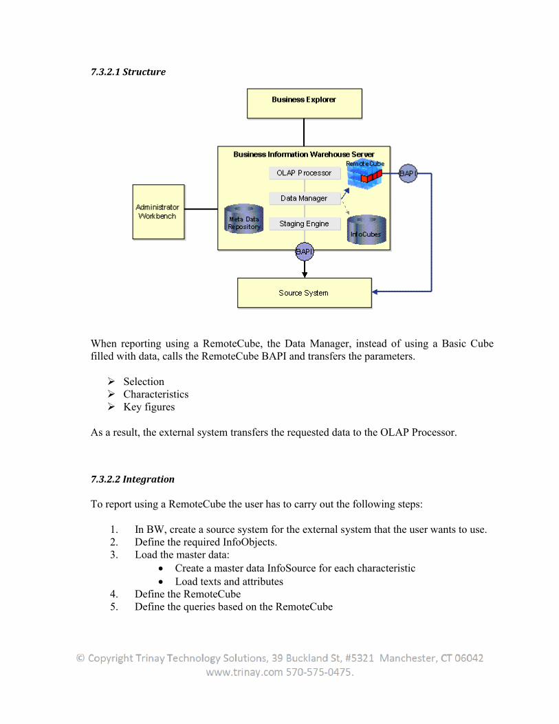
7.3.2.1 Structure
When reporting using a RemoteCube, the Data Manager, instead of using a Basic Cubefilled with data, calls the RemoteCube BAPI and transfers the parameters.
Selection Characteristics Key figures
As a result, the external system transfers the requested data to the OLAP Processor.
7.3.2.2 Integration
To report using a RemoteCube the user has to carry out the following steps:
1. In BW, create a source system for the external system that the user wants to use. 2. Define the required InfoObjects. 3. Load the master data:
Create a master data InfoSource for each characteristic Load texts and attributes
4. Define the RemoteCube 5. Define the queries based on the RemoteCube
7.3.3 Virtual InfoCubes with Services
A virtual InfoCube with services is an InfoCube that does not physically store its own data in BW. The data source is a user-defined function module. The user has a number of options for defining the properties of the data source more precisely. Depending on these properties, the data manager provides services to convert the parameters and data.
The user uses a virtual InfoCube with services if the user wants to display data from non-BW data sources in BW without having to copy the data set into the BW structures. The data can be local or remote. The user can also use the user own calculations to change the data before it is passed to the OLAP processor.
This function is used primarily in the SAP Strategic Enterprise Management (SEM) application.
In comparison to the RemoteCube, the virtual InfoCube with services is more generic. It offers more flexibility, but also requires more implementation effort.
7.3.3.1 Structure
When the user creates an InfoCube the user can specify the type. If the user chooses Virtual InfoCube with Services as the type for the user InfoCube, an extra Detail pushbutton appears on the interface. This pushbutton opens an additional dialog box, in which the user defines the services.
1. Enter the name of the function module that the user wants to use as the data source for the virtual InfoCube. There are different default variants for the interface of this function module. One method for defining the correct variant, together with the description of the interfaces, is given at the end of this documentation.
2. The next step is to select options for converting/simplifying the selection conditions. The user does this by selecting the Convert Restrictions option. These conversions only change the transfer table in the user-defined function module. The result of the query is not changed because the restrictions that are not processed by the function module are checked later in the OLAP processor.
Options:
No restrictions: if this option is selected, any restrictions are passed to the InfoCube.
Only global restrictions: If this option is selected, only global restrictions (FEMS = 0) are passed to the function module. Other restrictions (FEMS > 0) that are created, for example, by setting restrictions on columns in queries, are deleted.
Simplify selections: Currently this option is not yet implemented. Expand hierarchy restrictions: If this option is selected, restrictions on
hierarchy nodes are converted into the corresponding restrictions on the characteristic value.
3. Pack RFC: This option packs the parameter tables in BAPI format before the function module is called and unpacks the data table that is returned by the function module after the call is performed. Since this option is only useful in conjunction with a remote function call, the user have to define a logical system that is used to determine the target system for the remote function call, if the userselect this option.
4. SID support: If the data source of the function module can process SIDs, the userShould select this option.
If this is not possible, the characteristic values are read from the data source and the data manager determines the SIDs dynamically. In this case, wherever possible, restrictions that are applied to SID values are converted automatically into the corresponding restrictions for the characteristic values.
5. With navigation attributes: If this option is selected, navigation attributes and restrictions applied to navigation attributes are passed to the function module.If this option is not selected, the navigation attributes are read in the data manager once the user-defined function module has been executed. In this case, in the query, the user need to have selected the characteristics that correspond to these attributes. Restrictions applied to the navigation attributes are not passed to the function module in this case.
6. Internal format (key figures): In SAP systems a separate format is often used to display currency key figures. The value in this internal format is different from the correct value in that the decimal places are shifted. The user use the currency tables to determine the correct value for this internal representation.If this option is selected, the OLAP processor incorporates this conversion during the calculation.
7.3.3.2 Dependencies
If the user uses a remote function call, SID support must be switched off and the hierarchy restrictions must be expanded.
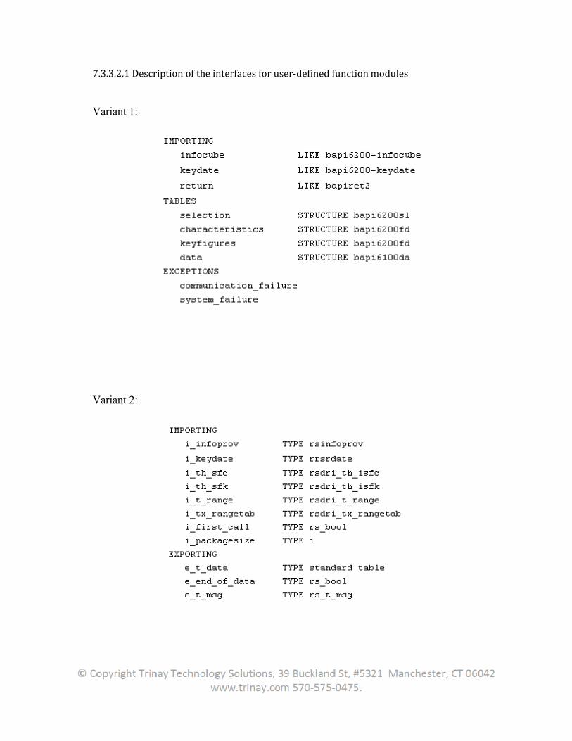
7.3.3.2.1 Description of the interfaces for user
Variant 1:
Variant 2:
Description of the interfaces for user-defined function modules
7.3.3.2.2 Additional parameters for variant 2
With hierarchy restrictions, an entry for the 'COMPOP' = 'HI' (for hierarchy) field is created at the appropriate place in table I_T_RANGE (for FEMS 0) or I_TX_RANGETAB (for FEMS > 0), and the 'LOW' field contains used to read the corresponding hierarchy restriction from table I_TSX_HIER, using field 'POSIT' . Table i_tsx_hier has the following type:
Variant 3:
SAP advises against using this interface.The interface is intended for internal uNote that SAP may change the structures used in the interface.
7.3.3.3 Method for determining the correct variant for the interfaceThe following list describes the procedure for determining the correct
interface for the user-defined function module. Go through the list from top to the bottom. The first appropriate case is the variant that
If Pack RFC is activated: Variant 1If SID Support is deactivated: Variant 2
Additional parameters for variant 2 for transferring hierarchy restrictions
With hierarchy restrictions, an entry for the 'COMPOP' = 'HI' (for hierarchy) field is created at the appropriate place in table I_T_RANGE (for FEMS 0) or I_TX_RANGETAB (for FEMS > 0), and the 'LOW' field contains a number that can be used to read the corresponding hierarchy restriction from table I_TSX_HIER, using field 'POSIT' . Table i_tsx_hier has the following type:
SAP advises against using this interface.The interface is intended for internal use only and only half of it is given here. Note that SAP may change the structures used in the interface.
Method for determining the correct variant for the interfaceThe following list describes the procedure for determining the correct
defined function module. Go through the list from top to the bottom. The first appropriate case is the variant that the user should use:
is activated: Variant 1is deactivated: Variant 2
for transferring hierarchy restrictions
With hierarchy restrictions, an entry for the 'COMPOP' = 'HI' (for hierarchy) field is created at the appropriate place in table I_T_RANGE (for FEMS 0) or
a number that can be used to read the corresponding hierarchy restriction from table I_TSX_HIER, using field
se only and only half of it is given here.
The following list describes the procedure for determining the correct defined function module. Go through the list from top to the bottom.


![Sap Bw Extraction Book for Beginners[1]](https://img.dokumen.tips/doc/110x75/545dbdb7b1af9f2d0a8b4d7e/sap-bw-extraction-book-for-beginners1.jpg)