Embed Size (px)
Citation preview

SA
IN
OP
MA
M
AFETY
STALLATIO
PERATION
AINTENAN
M A N U
ON
NCE
U A L
O
ww
S
Mod
NoRe
9575 N. Omaha, Nebra
(402)
ww.intersyst
SAMP
del GS
o. PC 519evised 200
109th Ave. ska 68142 330‐1500
tems.net
PLER
SS‐U
9824C 9‐08‐07

1
Table of Contents I. GENERAL SAFETY INFORMATION .....................................................................................................................3 II. GENERAL INFORMATION ...................................................................................................................................5
2.1 System Description .................................................................................................................................5 2.2 Optional Features ...................................................................................................................................6 2.3 Material Sampled....................................................................................................................................6 2.4 Sampler Construction .............................................................................................................................6
III. GENERAL INSTALLATION REQUIREMENTS ....................................................................................................7 3.1 Receiving Inspection...............................................................................................................................7 3.2 Pre-Installation Preparation ....................................................................................................................7 3.3 Location ..................................................................................................................................................7 3.4 General Mounting Guidelines .................................................................................................................7 3.4.1 Factory Pre-Mounted Sampler.............................................................................................................8 3.4.3 Field-Mounted Sampler Using Weld-On Plates ...................................................................................8 3.5 Material Sample Transport Lines............................................................................................................9 3.6 Controller Location..................................................................................................................................9 3.7 System Wiring.......................................................................................................................................10 3.7.1 Electrical Power Requirements, System............................................................................................10 3.7.1.1 Controller ........................................................................................................................................10 3.7.1.2 Clutch Solenoid Coil........................................................................................................................10 3.7.1.3 Drive Motor .....................................................................................................................................10
IV. OPERATIONS AND ADJUSTMENTS................................................................................................................11 4.1 Control Components And Their Functions............................................................................................11 4.1.1 POWER OFF/ON Switch S-2 ............................................................................................................12 4.1.2 SAMPLING MODE Switch S-3 (Automatic/Manual) ..........................................................................12 4.1.3 MANUAL SAMPLING Switch S-4 ......................................................................................................12 4.1.4 CONTINUOUS SAMPLING Switch S-5.............................................................................................12 4.1.5 POWER Pilot Light.............................................................................................................................12 4.1.6 SAMPLING Pilot Light........................................................................................................................12 4.1.7 Digital Display Timer T-1 (Standard)..................................................................................................13 4.1.8 Digital Display Counter C-1 (Optional)...............................................................................................14 4.1.9 Printed Circuit Board..........................................................................................................................15 4.1.9.1 Main Fuse .......................................................................................................................................15 4.1.9.2 Motor Fuse......................................................................................................................................15 4.1.9.3 PC Board Fuse F3 ..........................................................................................................................15 4.1.9.4 Motor Timer Switches (Tens & Ones).............................................................................................15 4.1.9.5 Solenoid Timer Switches (Tens & Ones) ........................................................................................16 4.1.9.6 Motor LED Indicator ........................................................................................................................16 4.1.9.7 Solenoid LED Indicator ...................................................................................................................16 4.1.9.8 Mode Select Switch ........................................................................................................................16 4.1.9.9 Terminal Strip..................................................................................................................................16 4.1.9.10 115V/230V Switch.........................................................................................................................17 4.2 Sampler Mounted Electrical Components.............................................................................................17 4.2.1 Limit Switch........................................................................................................................................17 4.2.2 Drive Motor ........................................................................................................................................17 4.2.3 Clutch Solenoid..................................................................................................................................18
V. MAINTENANCE AND REPAIR ...........................................................................................................................19 5.1 General Maintenance............................................................................................................................19 5.2 Periodic Inspection................................................................................................................................19 5.3 Lubrication ............................................................................................................................................19 5.3.1 Auger & Auger Tube Spur Gears.......................................................................................................19 5.3.2 Gear Reducer ....................................................................................................................................20 5.4 Mechanical Repair Procedures.............................................................................................................20

2
5.4.1 Limit Switch Cam Adjustment ............................................................................................................20 5.4.2 Clutch Solenoid Replacement And Adjustment .................................................................................21 5.4.3 Clutch Replacement & Timing ...........................................................................................................22
VI. TROUBLESHOOTING .......................................................................................................................................23 6.1 General GSS-U Sampler Troubleshooting ...........................................................................................23 6.2 PC Board Troubleshooting....................................................................................................................24
VII. REPLACEMENT PARTS...................................................................................................................................25 7.1 Scope....................................................................................................................................................25 7.2 Ordering Parts ......................................................................................................................................25 7.3 Replacement Parts ...............................................................................................................................25 7.4 Repair Kits ............................................................................................................................................25
VIII. WARRANTY.....................................................................................................................................................29
List Of Illustrations & Drawings FIGURE 1-1, GSS-U SAMPLER SAFETY LABEL LOCATIONS ...............................................................................4 FIGURE 2-1, TYPICAL INSTALLATION, MODEL GSS-U SAMPLING SYSTEM......................................................5 FIGURE 4-1, STANDARD NEMA 4 CONTROL PANEL DETAIL.............................................................................11 FIGURE 4-2, PRINTED CIRCUIT BOARD...............................................................................................................15 FIGURE 4-3, LIMIT SWITCH CONNECTIONS........................................................................................................17 FIGURE 5-1, LIMIT SWITCH CAM ADJUSTMENT .................................................................................................20
DRAWING 525255, GSS-U SAMPLER DRIVE END SECTION VIEW....................................................................28 DRAWING 525256, GSS-U SAMPLER DISCHARGE END SECTION VIEW & PARTS LIST ................................29

3
I. GENERAL SAFETY INFORMATION SAFETY FIRST! The symbols shown identify examples of the safety labels and signs to be found on Intersystems equipment. They are affixed to the equipment to warn of danger to persons and of possible equipment damage. These signs must never be removed, tampered with, painted over or obscured in any way. (See Page 4 for label locations.) If labels are damaged or become unreadable, replacement labels are available from Intersystems. The user must institute a continuing program to instruct all personnel in safe operating and maintenance procedures, and to insure that all safety devices, guards, and covers are intact and operable, and that all safety signs are legible. Consult Intersystems before making any changes to the sampler or its operating environment. Careless changes could result in death or serious injury to people, and reduce the performance and service life of the equipment. Never perform any service on this equipment or any other powered equipment until all power has been shut off and locked out so that it cannot be restored without the consent and knowledge of the person who interrupted power. Power includes electrical, fluid, mechanical, or pneumatic energy. Never perform any service on this equipment without utilizing the required PPE (personal protective equipment). Refer to the MSDS(s), material safety data sheet(s), on all the products to which this equipment is in contact with to determine what PPE is required.
DANGER THIS EQUIPMENT IS TO BE OPERATED ONLY ON THE VOLTAGE DESIGNATED ON THE CERTIFIED ELECTRICAL DRAWING(S)! FIRE OR EXPLOSION MAY RESULT, WHICH CAN CAUSE DEATH, SERIOUS INJURY, AND EXTENSIVE DAMAGE TO EQUIPMENT. DO NOT CONNECT TO VOLTAGES OTHER THAN DESIGNATED.

4
FIGURE 1-1, GSS-U SAMPLER SAFETY LABEL LOCATIONS

5
II. GENERAL INFORMATION
2.1 System Description The GSS-U Sampler is designed to collect a representative sample of granular, flake, powder, or other materials in a gravity conveying line or from a hopper tank. Figure 2-1 illustrates a typical GSS-U Sampler application. Sample collection is initiated in response to either an operator's manual command or a signal automatically generated by controller logic, usually time-based but which could also be volume or quantity based. A sample cycle begins when an electric motor operating through a right angle gear reducer rotates the drive housing input shaft. The clutch solenoid, which energizes at the same time the motor starts, allows the slotted sampling tube (auger tube) in the product line to rotate through one revolution to collect a sample of the material. As the auger tube rotates the sample auger also is turning and continues to auger material out of the auger tube for a period of time after the auger tube stops rotating. The sample then falls down and out the 2.00" (51mm) OD discharge tube to the desired sample collection point, at which point an Intersystems SCS Sample Collection System (optional) may be installed.
FIGURE 2-1, TYPICAL INSTALLATION, MODEL GSS-U SAMPLING SYSTEM

6
2.2 Optional Features The certified drawings indicate which, if any, optional features are included with a sampling system. Some of the more frequently specified optional features are briefly described in the following list.
A. Controller arranged to initiate a sampling cycle based on quantity or volume of material passing through conveying line rather than upon elapsed time periods.
B. Explosion-Proof Sampling System. There are several major differences in an explosion-proof sampler as
compared to a standard sampling system. An explosion proof sampler will typically have the following features. 1. An explosion-proof clutch solenoid with the rating of: (Std, furnished on all GSS-U samplers) Class 1, Groups C & D, Division 1 & 2 Class 2, Groups E, F & G, Division 1 & 2 2. An explosion-proof limit switch with the rating of: (Std, furnished on all GSS-U samplers) Class 1, Groups C & D, Division 1 & 2 Class 2, Groups E, F & G, Division 1 & 2 3. An explosion-proof motor with the rating of: (Optional) Class 1, Groups D, Division 1 & 2 Class 2, Groups E, F & G, Division 1 & 2 The explosion proof sampler control is available in two enclosure classifications. 1. The NEMA 9 control with the rating of: Class 2, Groups E, F & G, Division 1 & 2 2. The NEMA 7 control with the rating of: Class 1, Groups C & D, Division 1 & 2 Class 2, Groups E, F & G, Division 1 & 2
C. Components of special materials, such as 316 stainless steel, monel, inconel or nedox coatings. D. Programmable Controls to sequence the sampler and the sample collection equipment.
2.3 Material Sampled Most materials from light to heavy density powders, granules, flakes and pellets.
2.4 Sampler Construction Standard sampler housing construction is of painted cast aluminum. The sample auger & auger tube are of type 304 Stainless Steel. The auger is machined from a solid bar (no welds on flights) and hand polished. The sanitary GSS-U sampler design allows for quick removal of the auger and auger tube for easy clean-out and washing. Other materials and/or finishes appropriate to the operating environment and the material or product being sampled may be used. Refer to the certified drawing(s) for any optional or special components installed on the sampler.

7
III. GENERAL INSTALLATION REQUIREMENTS 3.1 Receiving Inspection Carefully inspect the sampling system for damage as soon as it is received. Also, verify that the quantity of parts or packages actually received corresponds to the quantity shown on the packing slip. Report any damage or shortage to the delivering carrier as soon as possible. Intersystems' responsibility for the equipment ended with acceptance by the delivering carrier. Refer to the bill of lading.
3.2 Pre-Installation Preparation Note, before starting sampling system installation, study this manual, the certified drawing(s) furnished with the system, and other applicable documents (including, but not limited to OSHA Regulations; the National Electrical Code; and all other applicable federal, state, and local codes and regulations).
3.3 Location The GSS-U sampler is typically mounted horizontally onto a vertical gravity flow conveying line carrying the product to be sampled as in Figure 2-1. The sampler axis must be installed perpendicular (at a 90 degree angle) to the axis of the product line for optimum performance. Additionally, the sampler should be located where the product has a non-turbulent flow pattern. The sampler and associated equipment should be located for ease of access and maintenance. The sampler is to be installed only as shown on the certified drawing(s). If an alternate mounting arrangement is desired, contact Intersystems prior to installation for proper guidance. The sampler is of a general design with modifications specifically for your application. It may be necessary to rework the sampler in order for it to function properly if you alter the application.
3.4 General Mounting Guidelines The sampler assembly is designed to support ONLY its own weight.
DANGER SAMPLER CANNOT SUPPORT ANY OTHER EQUIPMENT OR CONVEYING LINE! COLLAPSE OF THE WHOLE SYSTEM CAN CAUSE DEATH, SERIOUS INJURY, AND EXTENSIVE DAMAGE TO EQUIPMENT. PROPERLY SUPPORT ALL SPOUTS, CONTAINERS, AND CONVEYING LINES.

8
NOTE: IF THE SURFACE AREA TO WHICH THE MOUNTING PLATE IS TO BE ATTACHED IS WARPED OR BENT, STRAIGHTEN AND SMOOTH THE METAL SO THE SAMPLER WILL BE PROPERLY ALIGNED WHEN THE INSTALLATION IS COMPLETE. THE SURFACE TO WHICH THE SAMPLER IS MOUNTED MUST NOT FLEX.
NOTE: OVER TIGHTENING THE MOUNTING FASTENERS WILL WARP OR CRACK THE SEAL HOUSING FLANGE. IMPROPER SAMPLING WILL RESULT.
3.4.1 Factory Pre-Mounted Sampler As furnished, the premounted sampler is already firmly attached to a length of tube, pipe, etc.
A. Remove a section of pipe or chute work where the sampler is to be installed. B. Remove the sampler from the sampler premount by removing the hinge pins and remove the auger & auger tube. C. Locate the sampler premount in the desired position. D. Attach the sampler premount using one of the following methods.
1-Weld the sampler premount ends directly to the existing pipe or chute work. 2-Clamp the sampler premount ends to the existing pipe utilizing compression couplings. 3-Weld matching flanges to the existing pipe or chute work and sampler premount.
E. Re-install the auger & auger tube. Verify that the auger tube rotates without interference. F. Install the sampler drive assembly by re-installing the hinge pins.
3.4.3 Field-Mounted Sampler Using Weld-On Plates Weld-on plates are typically used when mounting the sampler to a large existing surface, such as on a storage hopper or a long section of chutework.
A. Locate and mark the desired mounting location on the conveying line. B. Cut and de-burr two 4" diameter holes (opposite each other) in the product line through which the sample tube will pass to collect material samples. C. Position the sampler drive mounting plate by centering the auger hole over the 4" diameter clearance holes. D. Tack weld the sides of the mounting plate to the product line surface and double check alignment. E. Weld a continuous bead around all sides of the mounting plate. Also from the inside of the chute weld a continuous bead around the 4" diameter clearance hole.
NOTE: WHEN WELDING THE MOUNTING PLATE TO THIN GAUGE SHEET OR THIN PLATE, SKIP WELD ALTERNATING SIDES OF THE MOUNTING PLATE TO LIMIT HEAT INPUT TO MINIMIZE WARPING.
F. Insert the auger tube through the drive mount plate and verify that the auger tube rotates without interference. G. Locate the discharge mounting plate assembly by slipping it over the end of the auger tube.

9
I. Tack weld the sides of the mounting plate to the product line surface and double check alignment. Also from the inside of the chute weld a continuous bead around the 4" diameter clearance hole. J. Re-install the auger tube an re-verify that the auger tube rotates without interference. K. Remove the auger tube. Grind and polish the interior welds to sanitary requirements. L. Re-assemble the sampler auger, auger tube, bearings, o-rings, drive coupling, drive unit, discharge tee, etc.
3.5 Material Sample Transport Lines The tubing used to transport material samples must be compatible with the operating environment and the material sampled. The sampler has a 2" OD "Tri-Clover" type sanitary connection. Using the appropriate compatible adapters, route the sample to allow material to flow via gravity to a convenient collection point. At that point the sample line may be connected to a collection jar bracket or a Sample Collection System cabinet. Make all connections airtight and make sure all interior surfaces of joints are smooth and flush. Any ragged or raised tube ends will collect dust and debris as well as retard material flow. Air leaks can interfere with the pressure or vacuum conveying and sampling system. Escaping sample material can contaminate surrounding atmosphere and equipment.
3.6 Controller Location
A. Use vibration isolation pads when mounting the control enclosure or mount the controller in a vibration-free location. B. Unless ordered for severe duty, locate controller so it is protected from water and dust. C. Unless an explosion-proof rated controller was specifically ordered, DO NOT locate the controller in a hazardous area. D. Most applications require that the sampler be in easy view of the controller.

10
3.7 System Wiring Refer to the certified electrical drawing(s) for specific wiring requirements. As explained in Paragraph 4.1.9.9, the 20-position barrier terminal strip on the circuit board mounted INSIDE the controller enclosure is the connection point for ALL external circuitry. The controller was completely assembled and tested with the sampler before it left the factory. The electrical installation must comply with OSHA Regulations; the National Electrical Code; and all other applicable federal, state, and local codes and regulations. If wiring between the controller and the sampler unit is run through rigid conduit, use a short length of flexible conduit to connect wiring to the sampler. This will isolate the rigid conduit from any vibration originating in the product conveying line and sampler.
3.7.1 Electrical Power Requirements, System 110/120 VAC 50/60 Hz, Single Phase, 15 Amp Service. Optional - 220/240 VAC 50/60 Hz, Single Phase, 10 Amp Service. Refer to the certified electrical drawing(s) for specific wiring requirements. Intersystems strongly recommends that electrical service to the sampling system be an isolated line. Voltage fluctuations and line noise can affect the controller's circuit board, thus causing the sampler to malfunction.
3.7.1.1 Controller 110/120 VAC, 50/60 Hz, Single Phase, 12 Amp Max. (includes motor power requirements). Optional - 220/240 VAC, 50/60 Hz, Single Phase, 6 Amp Max. (includes motor power requirements).
3.7.1.2 Clutch Solenoid Coil 110/120 VAC, 50/60 Hz, Single Phase, 17.1 Watts. Optional - 220/240 VAC, 50/60 Hz, Single Phase, 17.1 Watts.
3.7.1.3 Drive Motor Standard 110/120 VAC, 220/240 VAC, 50/60 Hz, Single Phase, 6.6/3.3 Full Load Amps.

11
IV. OPERATIONS AND ADJUSTMENTS
DANGER
FAILURE TO OBSERVE ALL SAFETY RULES, WRITTEN AND IMPLIED, AND THOSE SUGGESTED BY COMMON SENSE, CAN RESULT IN DEATH, SERIOUS INJURY, AND /OR EQUIPMENT DAMAGE. LOCKOUT POWER BEFORE PERFORMING ANY MAINTENANCE.
4.1 Control Components And Their Functions
FIGURE 4-1, STANDARD NEMA 4 CONTROL PANEL DETAIL
Refer to the certified electrical drawing(s) for dimensions on control panels with optional features.

12
4.1.1 POWER OFF/ON Switch S-2 This toggle switch controls all electrical power to the controller and the sampler unit.
WARNING
THIS MACHINE STARTS WITHOUT WARNING. MOVING PARTS CAN CAUSE SEVERE INJURY. CLEAR AREA PRIOR TO CONTROLLER START-UP.
4.1.2 SAMPLING MODE Switch S-3 (Automatic/Manual) This switch permits the operator to select whether samples will be collected automatically at precisely timed or counted intervals as determined by the Digital Display Timer (T-1) or Counter C-1, OR manually whenever the operator momentarily actuates the MANUAL SAMPLING toggle switch (S-4).
4.1.3 MANUAL SAMPLING Switch S-4 This switch functions ONLY when the AUTO/MANUAL switch has been set to the Manual Mode position. Switch S-4 is a spring-return switch that is maintained in the OFF or Normally Open position. Correct operating procedure is to momentarily actuate S-4 to the Start position. When the SAMPLING light is illuminated, release the switch. The sampler will complete its cycle without further operator intervention.
4.1.4 CONTINUOUS SAMPLING Switch S-5 This switch functions ONLY when the AUTO/MANUAL switch has been set to the Manual Mode position. Setting the Continuous Sampling switch S-5 to the ON position causes the auger and auger tube to rotate as long as the switch is left in the ON position. When the switch is set to OFF the auger tube will return to its home position and the auger will run for a short period to empty out the sampler.
4.1.5 POWER Pilot Light This light is illuminated as long as power is available to the controller and the POWER switch (S-2) is set to ON.
4.1.6 SAMPLING Pilot Light This light will illuminate when a sampling cycle has been initiated and will stay lit until the sampling cycle has completed.

13
4.1.7 Digital Display Timer T-1 (Standard) As arranged for use in this system, the timer operates in the DOWN & STOP mode. When the AUTO mode is selected, the illuminated display resets to the value dialed in to the Three Digit Preset. Immediately, the timer begins timing down. When the illuminated display reads all zeroes (000), the timer has "timed out" and initiates a sampling cycle. The auger tube rotates once to collect a sample, and the auger rotates to empty out the sampler. When the auger motor is energized the timer T-1 is reset (powered off). When the motor stops, the timer display resets to the preset value and another timing interval is initiated. If the controller is shut off or the mode switched from AUTO to MANUAL, the timing cycle is terminated. When power is restored or the AUTO mode is again selected, the display is reset to the preset value and another cycle begins. NOTE: A new timing cycle can be initiated ONLY after the sampling cycle has completed.
A. External Settings
1. THE DISPLAY:
The high intensity blue fluorescent display consists of three digits and decimal point (if decimal is set in tenths or hundredths position). Also, there is a blinking Timing Bar and a special Time-Out symbol. The Timing Bar appears to the right of the digits and blinks once every second during timing. The Timing Bar shows quickly that the timer is actively timing especially when the digits do not change rapidly as in the "hours" ranges. When the delay relay is energized at time-out, a triangular Time-Out symbol appears to the left of the digits. The Timing Bar blinks noticeably faster at time-out.
2. SETTING SWITCHES:
The three digits are set with the rotary switch knobs located beneath each digit. These knobs can be rotated in either direction (CW or CCW), and they are "pull" removable if digit set security is desired. Changing one or more digits, during timing, will instantly be reflected by an equivalent change in the timer's display. Setting all three digits to zero will cause instant time-out of the timer.
B. Internal Settings
THE 365 DIGITAL DISPLAY TIMER MUST BE REMOVED FROM ITS HOUSING TO ALTER ANY OF THE FOLLOWING SETTINGS. 1. TIME RANGE:
Decimal Point Location can be changed with the white plastic lever mounted behind the front face of the timer. This lever moves into three positions. With finger force you can change its position and at the same time observe the front of the timer. NOTE - this procedure sets the decimal point electronically as well as visually. Time Units (Sec/Min/Hr) are set by moving a small width metal arm in a slotted arc on the side plate nearest to the units (Sec/Min/Hr) window. By depressing this arm slightly with a pencil or pen point, it can be moved to a new position. The time units physically change in the timer's face and the timer is electronically switched to the new units as well.
2. LINE FREQUENCY:
To set the proper line frequency, connect the jumper wire to either the 50 HZ or 60 HZ pin. These pins are clearly marked on the side of the timer.
NOTE: THE TIMER CHASSIS AND THE HOUSING ARE POLARIZED SO THAT THE CHASSIS CANNOT BE INSERTED INTO ITS HOUSING UPSIDE-DOWN. IF THE TIMER IS FORCED INTO THE HOUSING UPSIDE-DOWN DAMAGE WILL RESULT.

14
4.1.8 Digital Display Counter C-1 (Optional) As arranged for use in this system, the counter operates in the DOWN & STOP mode. When the AUTO mode is selected, the illuminated display resets to the value dialed in to the Three Digit Preset. Immediately, the counter begins counting down. When the illuminated display reads all zeroes (000), the counter has "counted out" and initiates a sampling cycle. The auger tube rotates once to collect a sample, and the auger rotates to empty out the sampler. When the auger motor is energized the counter C-1 is reset (powered off). When the motor stops, the counter display resets to the preset value and another counting interval is initiated. If the controller is shut off or the mode switched from AUTO to MANUAL, the counting cycle is terminated. When power is restored or the AUTO mode is again selected, the display is reset to the preset value and another cycle begins. NOTE: A new counting cycle can be initiated ONLY after the sampling cycle has completed.
A. External Settings
1. THE DISPLAY:
The high intensity blue fluorescent display consists of three digits and a Counting Bar with a special Count-Out symbol. The Counting Bar appears to the right of the digits and blinks once every count, regardless of range. When the delay relay is energized at count-out, a triangular Count-Out symbol appears to the left of the digits.
2. SETTING SWITCHES:
The three digits are set with the rotary switch knobs located beneath each digit. These knobs can be rotated in either direction (CW or CCW), and they are "pull" removable, if digit set security is desired. Changing one or more digits, during counting, will instantly be reflected by an equivalent change in the counter's display. Setting all three digits to zero will cause instant count-out of the counter.
B. Internal Settings
THE 366 DIGITAL DISPLAY COUNTER MUST BE REMOVED FROM ITS HOUSING TO ALTER THE
COUNT RANGE: The 366 has three ranges. 1x = Counts single pulses to 999 10x = Counts every tenth pulse to 9,990 100x = Counts every hundredth pulse to 99,900 Each range is selectable using finger force on the white plastic lever behind the front face of the counter. In two of the three possible lever positions, an indicator will appear in a range window located on the front face of the counter. When nothing appears in this window the count is in the x 1 range.
NOTE: THE COUNTER CHASSIS AND THE HOUSING ARE POLARIZED SO THAT THE CHASSIS CANNOT BE INSERTED INTO ITS HOUSING UPSIDE-DOWN. IF THE COUNTER IS FORCED INTO THE HOUSING UPSIDE-DOWN DAMAGE WILL RESULT.
15
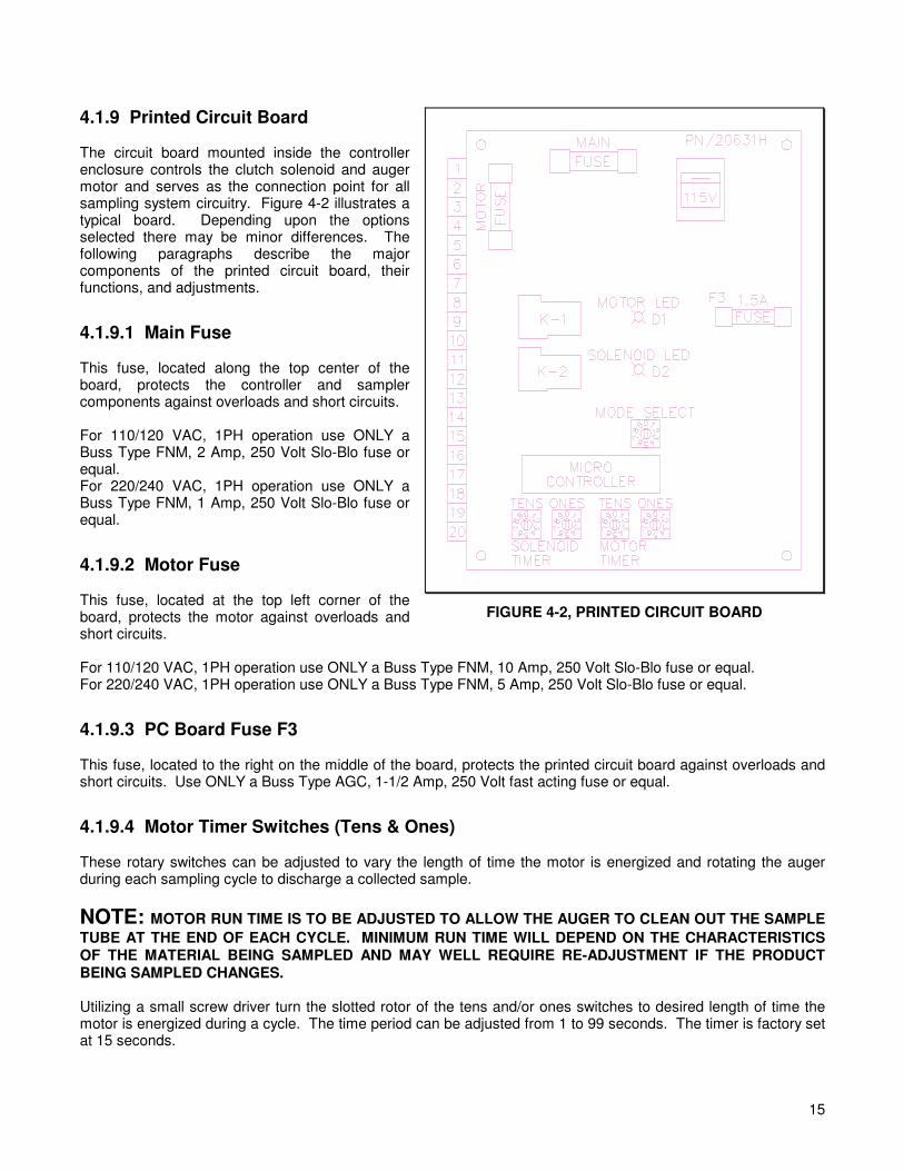
4.1.9 Printed Circuit Board The circuit board mounted inside the controller enclosure controls the clutch solenoid and auger motor and serves as the connection point for all sampling system circuitry. Figure 4-2 illustrates a typical board. Depending upon the options selected there may be minor differences. The following paragraphs describe the major components of the printed circuit board, their functions, and adjustments.
4.1.9.1 Main Fuse This fuse, located along the top center of the board, protects the controller and sampler components against overloads and short circuits. For 110/120 VAC, 1PH operation use ONLY a Buss Type FNM, 2 Amp, 250 Volt Slo-Blo fuse or equal. For 220/240 VAC, 1PH operation use ONLY a Buss Type FNM, 1 Amp, 250 Volt Slo-Blo fuse or equal.
4.1.9.2 Motor Fuse This fuse, located at the top left corner of the board, protects the motor against overloads and short circuits. For 110/120 VAC, 1PH operation use ONLY a Buss Type FNM, 10 Amp, 250 Volt Slo-Blo fuse or equal. For 220/240 VAC, 1PH operation use ONLY a Buss Type FNM, 5 Amp, 250 Volt Slo-Blo fuse or equal.
4.1.9.3 PC Board Fuse F3 This fuse, located to the right on the middle of the board, protects the printed circuit board against overloads and short circuits. Use ONLY a Buss Type AGC, 1-1/2 Amp, 250 Volt fast acting fuse or equal.
4.1.9.4 Motor Timer Switches (Tens & Ones) These rotary switches can be adjusted to vary the length of time the motor is energized and rotating the auger during each sampling cycle to discharge a collected sample.
NOTE: MOTOR RUN TIME IS TO BE ADJUSTED TO ALLOW THE AUGER TO CLEAN OUT THE SAMPLE TUBE AT THE END OF EACH CYCLE. MINIMUM RUN TIME WILL DEPEND ON THE CHARACTERISTICS OF THE MATERIAL BEING SAMPLED AND MAY WELL REQUIRE RE-ADJUSTMENT IF THE PRODUCT BEING SAMPLED CHANGES. Utilizing a small screw driver turn the slotted rotor of the tens and/or ones switches to desired length of time the motor is energized during a cycle. The time period can be adjusted from 1 to 99 seconds. The timer is factory set at 15 seconds.
FIGURE 4-2, PRINTED CIRCUIT BOARD

16
The ones switch is in increments of one second and the tens switch is in increments of ten seconds. As an example, to set the motor timer to 20 seconds, turn the tens rotor to setting 2 and turn the ones setting to 0. The solenoid timer setting would be set in the same manner.
4.1.9.5 Solenoid Timer Switches (Tens & Ones) These rotary switches can be adjusted to vary the length of time the clutch solenoid is energized to allow the auger tube to rotate in the product stream during each sample collection cycle.
NOTE: THE CLUTCH SOLENOID TIME IS ADJUSTED SO THAT THE AUGER TUBE MAKES ONE REVOLUTION. WHEN THIS TIMER TIMES OUT THE SOLENOID WILL STAY ENERGIZED VIA THE FIELD WIRING THRU THE LIMIT SWITCH. WHEN THE LIMIT SWITCH IS ACTIVATED POWER TO THE SOLENOID WILL CEASE AND THE CLUTCH WILL NO LONGER DRIVE THE AUGER TUBE. IF ADDITIONAL REVOLUTIONS ARE DESIRED: ADD SIX SECONDS TO THE SOLENOID AND MOTOR TIMER SETTINGS FOR EACH ADDITIONAL REVOLUTION. Utilizing a small screw driver turn the slotted rotor of the tens and/or ones switches to desired length of time the sample tube clutch solenoid is energized during a cycle. The time period can be adjusted from 1 to 99 seconds. The timer is factory set at 4 seconds. Refer to Section 4.1.9.4 for further explanation on time settings.
4.1.9.6 Motor LED Indicator This LED (D1) is illuminated when power is present to K-1 relay coil on the PC board. It is a visual signal showing when the motor should be running.
4.1.9.7 Solenoid LED Indicator This LED (D2) is illuminated when power is present to K-2 relay coil on the PC board. It is a visual signal showing when the clutch solenoid should be energized.
4.1.9.8 Mode Select Switch The switch, located at the lower center of the circuit board, determines the sequencing of certain internal controller events. As this board is used in controllers for several different samplers, MODE switch settings allow the board's functions to be tailored to the requirements of the various samplers.
NOTE: GSS-U SAMPLERS REQUIRE THE MODE SWITCH TO BE POSITIONED ON SETTING "2" (TWO). IF THE MODE SETTING IS NOT CORRECTLY SET, TURN POWER OFF TO THE CONTROL PRIOR TO RE-SELECTING. THE PC BOARD WILL ONLY CHANGE MODES WHEN POWER IS INITIALLY APPLIED.
4.1.9.9 Terminal Strip This 20-position barrier terminal strip is located along the left edge of the circuit board. It serves as the controller's interface and connection point for all external circuits and for the components mounted on the enclosure's front panel. Refer to the certified electrical drawing(s).

17
4.1.9.10 115V/230V Switch This switch is factory set to allow a common PC board to be operated on either 115 vac, 50/60 hz or 230 vac, 50/60 hz. The printed circuit board operating voltage can only be switched after all electrical components connected to it are changed. To field convert the control and sampler operating voltage, determine what components will need to be replaced. Typically this includes, but is not limited to: the digital display timer, power lamp & socket, fuse(s), solenoid coil(s), and possibly the motor. Refer to the name plate and wiring diagram on the motor to determine if the motor is rated for the desired voltage. If it is, change the wiring connections in the motor junction box for operation on the new voltage.
DANGER THIS CONTROL IS TO BE OPERATED ONLY ON THE VOLTAGE DESIGNATED ON THE CERTIFIED ELECTRICAL DRAWING! FIRE OR EXPLOSION MAY RESULT, WHICH CAN CAUSE DEATH, SERIOUS INJURY, AND EXTENSIVE DAMAGE TO EQUIPMENT. DO NOT CHANGE THE 115/230 VAC SWITCH SETTING WITHOUT CONSULTING INTERSYSTEMS.
4.2 Sampler Mounted Electrical Components
4.2.1 Limit Switch This switch is actuated when the auger tube is in its home position. Upon initiation of a sample cycle the auger tube rotates the cam tripping the limit switch. The normally closed contacts on the limit switch close and power is supplied directly to the clutch solenoid. When the limit switch is actuated the opening of the normally closed contacts removes power to the clutch solenoid thus stopping the auger tube rotation. Correct wiring termination is essential to proper sampler operation. Refer to figure 4-3, it shows the limit switch utilized on the GSS-U sampler and the physical orientation of the proper wiring connections.
4.2.2 Drive Motor This motor drives the sample auger and auger tube rotation through a right angle gear reducer and two independent sets of spur gears inside the drive housing. A label is located on the motor designating the correct direction of rotation (reference Figure 1-1). Verify that the motor is turning the proper direction of rotation when wiring the system. On initial setup, disconnect the motor from the gear reducer and test run the motor. This will prevent damage to the clutch if the motor is run backwards.
NOTE: DO NOT RUN THE MOTOR THE WRONG DIRECTION. EXTENSIVE DAMAGE TO THE SAMPLER WILL RESULT.
FIGURE 4-3, LIMIT SWITCH CONNECTIONS

18
4.2.3 Clutch Solenoid This solenoid, when energized, pulls the clutch actuator from the catch on the clutch and allows the clutch to engage. The output shaft on the gear reducer rotates the clutch and clutch gear which in turn rotates the auger tube.

19
V. MAINTENANCE AND REPAIR
DANGER
FAILURE TO OBSERVE ALL SAFETY RULES, WRITTEN AND IMPLIED, AND THOSE SUGGESTED BY COMMON SENSE, CAN RESULT IN DEATH, SERIOUS INJURY, AND /OR EQUIPMENT DAMAGE. LOCKOUT POWER BEFORE PERFORMING ANY MAINTENANCE.
5.1 General Maintenance A good maintenance program involves thorough general housekeeping, adequate periodic re-lubrication, and replacement of worn or damaged components.
5.2 Periodic Inspection At regularly scheduled intervals, while observing all safety precautions, observe the sampler as it operates. Inspect for:
A. Loose or missing hardware B. Noisy motor or motor/reducer bearings C. Overheated motor or reducer D. Adequate lubricant in gear reducer E. Structural damage F. Rust or corrosion G. Damaged wiring, including exposed conductors and connections H. Make sure that all guards are in place and that all warning labels are in place and legible. Section I, GENERAL SAFETY INFORMATION, explains the purpose and intended location of the warning signs. Warning signs are an important part of any safety program; replace any missing signs IMMEDIATELY!
5.3 Lubrication
5.3.1 Auger & Auger Tube Spur Gears The auger & auger tube spur gears are designed to run dry. If grease is applied to the gears, extra care must be taken to ensure that the grease remains free from contaminates.

20
5.3.2 Gear Reducer The gear reducer is shipped filled with oil. Check the oil level every six months and add oil if required. Under normal sampler operating conditions the oil should be changed once every two years. Use "Hub City #GL-460" gear lubricant, AGMA number 7 Comp., or equal. Lubricant must be compatible with bronze gear materials and nitrile rubber seals.
5.4 Mechanical Repair Procedures
5.4.1 Limit Switch Cam Adjustment The limit switch cam actuates the limit switch by pushing the switch plunger inward. The correct cam position is shown in Figure 5-1. Follow the instructions below.
A. Shutoff and lockout all power. B. Remove the six 1/4-20UNC hex head screws attaching the cover to the sampler drive housing. C. Loosen the two 1/4-20UNC hex head screws attaching the limit switch cam to the 120 tooth spur gear. D. Slide the limit switch cam to the position shown in Figure 5-1. Hold the 0.03" dimension and re-tighten the two 1/4-20UNC hex head screws.
FIGURE 5-1, LIMIT SWITCH CAM ADJUSTMENT

21
E. Make sure the thrust washers are in place on the auger shaft. Re-install the cover and gasket to the sampler drive housing. F. Re-install the cover fasteners and tighten.
5.4.2 Clutch Solenoid Replacement And Adjustment When following the instructions below, refer to the applicable drawing of the sampler. Reference the drawings in Section VII and the certified drawing(s).
A. Shutoff and lockout all power. B. Remove the six 1/4-20UNC hex head screws attaching the cover to the sampler drive housing. C. Disconnect the solenoid electrical connection and conduit. D. Remove the old solenoid from the solenoid bushing. E. Install the new solenoid (use care to avoid cross threading). F. Solenoid adjustment may be required. When solenoid is powered it should just clear the stop cog on the clutch. The solenoid will chatter and not release the clutch if positioned to far away. If positioned to close the clutch will not release. G. Make sure the thrust washers are in place on the auger shaft. Re-install the cover and gasket to the sampler drive housing. H. Re-install the cover fasteners and tighten.
22
5.4.3 Clutch Replacement & Timing When following the instructions below, refer to the applicable drawing of the sampler. Reference the section drawings of the sampler on pages 28 & 29, and the certified drawing(s).
A. Shutoff and lockout all power. B. Remove the six 1/4-20UNC hex head screws attaching the cover to the sampler drive housing. C. Loosen the #10-24UNC set screws attaching the 112 tooth spur gear to the reducer shaft and remove it, to permit access to the clutch. D. Loosen the 1/4-20UNC clutch set screw. Remove the clutch and 40 tooth spur gear from the reducer shaft. E. Remove the 40 tooth spur gear from the clutch and install it on the new clutch. F. Make sure key is in place on reducer shaft and re-install the clutch so that the clutch and limit switch cam are positioned as shown in figure 5-1. G. Turn the motor fan shaft by hand in the direction labeled on the motor and in figure 1-1. The clutch will rotate until the stop cog engages on the clutch actuator and stops further rotation of the auger tube. The limit switch cam should be the position as shown in figure 5-1. H. Re-time the gears if needed. Once the clutch and limit switch cam are in the correct position tighten the clutch set screw. I. Re-install the 112 tooth spur gear and tighten the set screws. The auger drive gears do not require any timing. J. Make sure the thrust washers are in place on the auger shaft. Re-install the cover and gasket to the sampler drive housing. K. Re-install the cover fasteners and tighten.

23
VI. TROUBLESHOOTING
6.1 General GSS-U Sampler Troubleshooting
DANGER CARELESS OR ACCIDENTAL RESTORATION OF POWER CAN RESULT IN DEATH OR SERIOUS INJURY. MAKE CERTAIN AREA IS CLEAR BEFORE REMOVING LOCKOUTS.
SYMPTOM POSSIBLE CAUSE CORRECTIVE ACTION Sampler does not cycle in either Power switch OFF. Turn power switch ON. auto or manual modes Circuit breaker is open. Reset breaker. (Power light Off). Main fuse is blown. Replace. Refer to Section 4.1.9.1. Faulty supply wiring. Correct. Refer to certified electrical
schematic. Defective power switch.
Replace switch.
Sampler does not cycle in either auto or manual modes
Faulty system wiring. Correct. Refer to certified electrical schematic.
(Power light On). PC board fuse is blown. Replace. Refer to Section 4.1.9.3. Motor fuse is blown. Replace. Refer to Section 4.1.9.2. Defective clutch solenoid.
Replace. Refer to Section 5.4.2.
Sampler timer T-1 digital display does not illuminate but sampler
Defective auto/manual switch S-2. Replace switch if line voltage is absent across #1 & #2 on timer T-1.
works in manual mode. Defective timer T-1.
Replace timer if line voltage is present across #1 & #2 on timer T-1.
Sample size too small or large. Solenoid time on setting too low or
high.
Adjust solenoid time setting on PC board refer to Section 4.1.9.5.
Auger tube doesn't stop at its home position.
Solenoid wired improperly.
Correct. Refer to the certified electrical schematic.
Sampler leaks air or material continuously out the sample discharge.
Sampler installed on a positive pressure line.
Relocate to a non pressurized line.

24
6.2 PC Board Troubleshooting SYMPTOM POSSIBLE CAUSE CORRECTIVE ACTION Motor fuse blows continuously . Motor wired improperly. Correct. Refer to the certified
electrical schematic. Motor jammed. Inspect & replace. Auger seized up in sampler. Inspect & replace. Mis-alignment of sampler mounting
flanges. Check mounting of sampler to ensure no binding is occurring.
Timer T-1 defective.
Inspect & replace. Refer to Section 4.1.7.
Sampler motor tries to start but does not run (control resets).
Low voltage power supply. 107 vac minimum for 110/120 vac. 215 vac minimum for 220/240 vac.
Inadequate power supply wiring. Monitor voltage when motor starts. It should not drop below 107 vac, or 215 vac.
Mis-alignment of sampler mounting flanges.
Check mounting of sampler to ensure no binding is occurring.
Sampler digital display timer T-1 does not illuminate when in auto
Motor fuse blown. Replace. Refer to Section 4.1.9.2.
mode. Defective PC board.
Replace.
Motor and/or solenoid times cannot be adjusted.
Defective PC board.
Replace.
Solenoid LED illuminates but no Defective PC board. Replace. full line voltage signal at terminal #13.
Improper ground wiring. Correct. See note below.
Motor LED illuminates but no full Motor fuse blown. Replace. Refer to Section 4.1.9.2. line voltage signal at terminal #10. Defective PC board. Replace. Improper ground wiring.
Correct. See note below.
NOTE: GSS-U SAMPLERS REQUIRE THE MODE SWITCH TO BE POSITIONED ON SETTING "2" (TWO). IF THE MODE SETTING IS NOT CORRECTLY SET, TURN POWER OFF TO THE CONTROL PRIOR TO RE-SELECTING. THE PC BOARD WILL ONLY CHANGE MODES WHEN POWER IS INITIALLY APPLIED.
NOTE: SAMPLER MAY FAIL TO OPERATE OR OPERATE IMPROPERLY IF THE DC GROUND TRACE ON THE PC BOARD IS NOT ISOLATED FROM THE AC GROUND OR NEUTRAL WIRING. REFER TO THE CERTIFIED ELECTRICAL DRAWING(S) FOR AC GROUND CONNECTIONS.

25
VII. REPLACEMENT PARTS
7.1 Scope The certified drawings list the non-standard components that have been incorporated into the equipment. Intersystems normally stocks non-fabricated parts and non-custom OEM parts. Replacement parts for any other components, including fabricated parts and custom OEM components can be supplied upon request.
7.2 Ordering Parts Direct parts orders or requests for technical assistance to your sales representative or to:
Intersystems 9575 N 109th AveOmaha, NE 68142 Phone 402.330.1500 Fax 402.330.3350
Please have available the MODEL NUMBER, SERIAL NUMBER and CUSTOMER ORDER NUMBER of the equipment in question as well as the location where the sampler is INSTALLED.
7.3 Replacement Parts The Intersystems sampler is a quality built piece of machinery. As with any machine, parts do wear out and fail. It is Intersystems' recommendation that a small supply of spare parts be kept on hand to cover any minor breakdowns. A separate priced Spare Parts List will be sent identifying the suggested spare parts. It is also necessary to check the certified drawings, which will list any special or custom components utilized on this equipment.
7.4 Repair Kits The Following chart lists repair kits and parts that are available from Intersystems. These kits are offered as a more economical solution by rebuilding the defective part rather than replacing it. However in some cases the part may be beyond repair and replacement will be necessary.
Product Code Description 512133 Clutch spring (Warner PSI-6) 527854 Replacement XP solenoid coil (Asco Red Hat II series)

26
This page intentionally left blank

27
REPLACE THIS PAGE WITH DRAWING 525255

28
REPLACE THIS PAGE WITH DRAWING 525256

29
VIII. WARRANTY Intersystems reserves the right to make changes in design or in construction of equipment and components without obligation to incorporate such changes in equipment and components previously ordered. WARRANTY, LIMITATION OF LIABILITY, DISCLAIMER OF IMPLIED WARRANTIES: Intersystems manufactured equipment and components are guaranteed against defects in workmanship or materials for one year from date of shipment. The obligation of Intersystems with respect to any goods is limited to replacement or repair of defective parts and equipment provided those parts are returned, shipping costs prepaid, to Intersystems' factory and provided the product has not been subject to misuse, negligence, or accident, or repaired or altered outside of our factory, or other than by an Authorized Service Representative. This warranty does not cover the replacement of parts inoperative because of wear occasioned by use, the cost of replacing parts by a person other than an Intersystems employee or an Authorized Service Representative, or the adjustment of a product where the product was improperly adjusted by the purchaser. In addition, this warranty does not cover components manufactured by others such as motors, drives, clutches, cylinders, valves, blowers, and the like. On those components the standard Manufacturers' warranty applies. In any event, liability is limited to the purchase price paid, and Intersystems will, under no circumstances, be responsible for special or consequential damages, or for incidental damages. INTERSYSTEMS NEITHER MAKES NOR AUTHORIZES ANY WARRANTY OTHER THAN AS HEREIN CONTAINED. THIS WARRANTY IS IN LIEU OF ALL OTHER WARRANTIES, EXPRESS OR IMPLIED, INCLUDING THOSE OF MERCHANTABILITY AND FITNESS FOR A PARTICULAR PURPOSE.