Embed Size (px)
Citation preview
Saline Effluent Management Plan
commercial-in-confidence Q-4200-15-MP-0003 Australia Pacific LNG Pty Limited ABN 68 001 646 331 Level 3, 135 Coronation Drive, Milton, Qld, 4064 GPO Box 148, Brisbane, Qld, 4001 • Telephone (07) 3858 0280• Facsimile 1300 863 446 • www.aplng.com.au 2
Table of Contents
1. Introduction ................................................................................................................. 4
1.1 Background .................................................................................................. 4 1.2 Objective of the Saline Effluent Management Plan ...................................... 5
2. Policy and Legislation ................................................................................................. 6
2.1 Environmental Protection Act 1994 / Environmental Protection Regulation 2008 .............................................................................................................. 6
2.2 CSG Water Management Policy ................................................................... 8
3. Production Profile ....................................................................................................... 9
3.1 Saline Effluent Flows .................................................................................... 9 3.2 Low pH Effluent .......................................................................................... 10 3.3 Saline Effluent Characteristics .................................................................... 10 3.4 Saline Effluent Profile ................................................................................. 11 3.5 Salt Profile .................................................................................................. 12
4. Saline Effluent Management Approach .................................................................... 14
4.1 Option Selection ......................................................................................... 14 4.2 Regulatory Framework & Guidance ........................................................... 15 4.3 Brine Ponds ................................................................................................ 16
5. Construction ............................................................................................................. 18
5.1 Statutory Regulations ................................................................................. 18 5.2 General Design Criteria .............................................................................. 19 5.3 Sizing of Ponds ........................................................................................... 21 5.4 Geotechnical Design Criteria ...................................................................... 23 5.5 Seepage Containment System ................................................................... 24 5.6 Windborne Salt Containment ...................................................................... 25 5.7 General Civil Design Criteria ...................................................................... 25 5.8 Safety in Design ......................................................................................... 25
6. Operation .................................................................................................................. 27
6.1 Operating Philosophies .............................................................................. 27 6.2 Leak Detection ............................................................................................ 27 6.3 Instrumentation ........................................................................................... 28 6.4 Solidification ............................................................................................... 28
7. Final Salt Disposal .................................................................................................... 30
7.1 Timeframe for Disposal Activities ............................................................... 30 7.2 Land Fill Development Considerations ....................................................... 30 7.3 Landfill Location .......................................................................................... 31 7.4 Transport to Landfill .................................................................................... 31
8. Brine Pond Decommissioning .................................................................................. 33
Saline Effluent Management Plan
commercial-in-confidence Q-4200-15-MP-0003 Australia Pacific LNG Pty Limited ABN 68 001 646 331 Level 3, 135 Coronation Drive, Milton, Qld, 4064 GPO Box 148, Brisbane, Qld, 4001 • Telephone (07) 3858 0280• Facsimile 1300 863 446 • www.aplng.com.au 3
8.1 Rehabilitation .............................................................................................. 33 8.2 Timeframe for Decommissioning of Brine Ponds ....................................... 34
9. Continuous Improvement ......................................................................................... 35
9.1 Brine Concentration .................................................................................... 35 9.2 Commercial Sale ........................................................................................ 36 9.3 Reinjection .................................................................................................. 36 9.4 Ocean Disposal .......................................................................................... 37 9.5 Solar Ponds ................................................................................................ 38 9.6 Algae Production ........................................................................................ 38
10. Risk Assessment ...................................................................................................... 39
11. Management Measures ............................................................................................ 40
11.1 Liner Failures .............................................................................................. 40 11.2 Bund Structural Failure ............................................................................... 40 11.3 Dryland Salinity ........................................................................................... 41 11.4 Drowning of Personnel / Fauna .................................................................. 41
12. Monitoring and Reporting ......................................................................................... 42
12.1 Regulated Dam Register ............................................................................ 42 12.2 Liner Integrity Monitoring ............................................................................ 43 12.3 Annual Regulated Dam Inspection ............................................................. 43 12.4 Groundwater Monitoring ............................................................................. 44 12.5 Water Balance Review ............................................................................... 45 12.6 Maintenance Requirements ........................................................................ 45 12.7 Operations and Monitoring Manual ............................................................ 45
13. Cumulative Impacts .................................................................................................. 46
13.1 Estimate ...................................................................................................... 46 13.2 Discussion .................................................................................................. 46
14. Review of the Saline Effluent Management Plan ..................................................... 48
15. References ............................................................................................................... 49
Saline Effluent Management Plan
commercial-in-confidence Q-4200-15-MP-0003 Australia Pacific LNG Pty Limited ABN 68 001 646 331 Level 3, 135 Coronation Drive, Milton, Qld, 4064 GPO Box 148, Brisbane, Qld, 4001 • Telephone (07) 3858 0280• Facsimile 1300 863 446 • www.aplng.com.au 4
1. Introduction
As part of the extraction of coal seam gas, coal seam gas (CSG) water is removed from the coal seam. CSG water is collected from wells associated with the Australia Pacific Liquefied Natural Gas (LNG) Project and aggregated at a number of water treatment facilities (WTF) where it is treated to provide high quality water for a number of end uses. As a result of the treatment process, a high salinity stream – saline effluent (also referred to as brine) is produced containing the majority of the salts removed from the CSG water.
The base case approach for saline effluent management across the Australia Pacific LNG project is to store effluent in suitably designed brine ponds during the project life, with transfer of evaporated solid salts to a licensed regulated waste disposal facility prior to the end of the project. At each Water Treatment Facility (WTF) a number of specially designed ponds are to be constructed. To aid natural salt crystallisation via evaporation, supersaturated salt solution will be removed from the ponds periodically and at the decommissioning stage. The saline effluent needs to be reduced to solid salt for its transfer to an off-site waste disposal facility.
A number of optimisation options are being investigated to reduce the requirement for large scale ponds and are discussed in Section 8 of this report.
This Saline Effluent Management Plan sets out the intended strategy to contain, concentrate, reuse and dispose of the salts contained in the saline effluent stream across the Australia Pacific LNG Project sites. This document forms Appendix 9 of the CSG Water Management Plan (formerly referred to as the Adaptive Associated Water Management Plan).
1.1 Background
Australia Pacific LNG is a 50:50 joint venture between Origin Energy and ConocoPhillips to develop CSG fields located in Queensland for supply to an LNG plant at Gladstone. The Project will comprise up to 10,000 CSG wells over 14 fields with water from these wells aggregated for treatment at up to 7 WTF’s. Infrastructure planned for the first five years of development is anticipated to include over 1,200 wells and two new water treatment plants.
The State Development and Public Works Organisation Act 1971 (SDPWO Act) provides a mechanism for ‘significant projects’ that will require numerous regulatory approvals, such as the Australia Pacific LNG Project, to be assessed initially by a whole-of-government environmental impact statement (EIS). This process is managed by the Coordinator General (CG) within the Department of Infrastructure and Planning (DIP), who is responsible for ensuring that the Project’s environmental, social and economic impacts are appropriately considered.
Australia Pacific LNG submitted an EIS addressing it’s required Terms of Reference (ToR) on 29th January 2010. The Coordinator General’s report, which is the Queensland State government approval for the Project, was received in November 2010. This plan has been prepared for all environmental management plans (EMP) as required for the expansion of the CSG fields in accordance with the conditions of the CG’s report, Appendix 2, Part 2, Condition 6 – Brine and Salts Management Plan. This condition requires a plan to address compliance with State policy, management and disposal of salt brought to the surface by

Saline Effluent Management Plan
commercial-in-confidence Q-4200-15-MP-0003 Australia Pacific LNG Pty Limited ABN 68 001 646 331 Level 3, 135 Coronation Drive, Milton, Qld, 4064 GPO Box 148, Brisbane, Qld, 4001 • Telephone (07) 3858 0280• Facsimile 1300 863 446 • www.aplng.com.au 5
project activities and a management plan for the management of secondary salinity. Conditions 9 and 18 also contain conditions relevant to the design and decommissioning of brine ponds respectively.
1.1.1 Nomenclature
For the purposes of the CSG Water Management Plan and subordinate documents including this Saline Effluent Management Plan, the reject stream from the treatment of CSG water will be referred to as saline effluent. This stream typically has a concentration of around 30 g/L total dissolved solids (TDS) but could foreseeably range from 15 to 50 g/L. The term brine refers to a solution of sodium chloride usually with other salts which is of a concentration greater than 40 g/L, total dissolved salts (seawater is approximately 35 g/L). In some cases the saline effluent is referred to as brine. Due to the fact that when saline effluent is concentrated via evaporation ponds, its concentration will increase beyond 40g/L, these evaporation ponds are referred to as brine ponds.
1.2 Objective of the Saline Effluent Management Plan
This Saline Effluent Management Plan will be the overarching document to outline the manner in which saline effluent streams across the Australia Pacific LNG Project are to be managed. It will seek to meet the following requirements:
Summarise the legislative background and current government policy stance
relevant to this issue
Provide current forecasts for quantities of saline effluent to be generated across the
Project sites
Document the chosen waste management approach including the design and
operation of saline effluent evaporation ponds (also referred to as brine ponds)
Discuss a range of options being considered and investigated for optimisation of
saline effluent management
Undertake a risk assessment of the saline effluent management system
Outline monitoring requirements which will detect any unintended releases of saline
effluent and prescribe remediation actions to be followed
Discuss potential cumulative impacts from the generation of brine across a number
of CSG developments across the state
Discuss the decommissioning or long term management requirements for Australia
Pacific LNG’s saline effluent management infrastructure
Allow for an adaptive approach to the provision of solutions for saline effluent management allowing for changing conditions both internal and external to the Project and continually improving outcomes where possible.
Saline Effluent Management Plan
commercial-in-confidence Q-4200-15-MP-0003 Australia Pacific LNG Pty Limited ABN 68 001 646 331 Level 3, 135 Coronation Drive, Milton, Qld, 4064 GPO Box 148, Brisbane, Qld, 4001 • Telephone (07) 3858 0280• Facsimile 1300 863 446 • www.aplng.com.au 6
2. Policy and Legislation
CSG water is managed under a complex legislative framework, such that:
CSG water extraction is authorised under the Petroleum and Gas (Production and Safety) Act 2004 or the Petroleum Act 1923.
Production of CSG and the associated CSG water must be authorised by an environmental authority issued under the Environmental Protection Act 1994 (EP Act). CSG water is a waste that must be either disposed of in accordance with the conditions of an environmental authority or used beneficially in accordance with a beneficial use approval.
The disposal of brine that may be created in the treatment of CSG water or the disposal of solid salt is also regulated under the EP Act. Brine and solid salt may also be used under a beneficial use approval.
For an overview of the regulatory setting for CSG water management for the Project in general, refer to section 2 of the CSG Water Management Plan (APLNG 2010).
2.1 Environmental Protection Act 1994 / Environmental Protection Regulation 2008
The object of this Act is to protect Queensland’s environment while allowing for development improving the total quality of life, both now and in the future, in a way that maintains the ecological processes on which life depends, (that is ecologically sustainable development).
The Environmental Protection Act 1994 (EP Act) requires a major project, such as Australia Pacific LNG's to apply for and subsequently operate under, an Environmental Authority (Petroleum Activities) (EA).
The storage, treatment or disposal of regulated waste is an Environmentally Relevant Activity (ERA), subject to exceptions. The EA approvals process will involve an assessment of ERAs that are listed as relevant petroleum activities. For any ERAs that are not listed as relevant petroleum activities, or are located outside the respective petroleum lease areas, a development approval may be required.
The EP Act provides an overarching framework for the assessment of the petroleum activity. Further guidance is provided in a series of Environmental Protection Policies (EPPs) made under the EP Act and in Operational policies issued by the Department of Environment and Resource Management (DERM). Of relevance to the management of saline effluent is the Environmental Protection (Waste Management) Policy 2000 and Environmental Protection (Waste Management) Regulation 2000.
2.1.1 Environmental Protection (Waste Management) Policy/ Regulation 2000
The EP Act defines waste to include anything that is “left over, or an unwanted by-product, from an industrial, commercial, domestic or other activity”. The Environmental Protection (Waste Management) Policy 2000 (the Policy) provides a strategic framework of managing
Saline Effluent Management Plan
commercial-in-confidence Q-4200-15-MP-0003 Australia Pacific LNG Pty Limited ABN 68 001 646 331 Level 3, 135 Coronation Drive, Milton, Qld, 4064 GPO Box 148, Brisbane, Qld, 4001 • Telephone (07) 3858 0280• Facsimile 1300 863 446 • www.aplng.com.au 7
waste whilst the Environmental Protection (Waste Management) Regulation 2000 (the Regulation) contains the requirements for handling specific waste streams.
The Policy prescribes the principle of the waste management hierarchy. The hierarchy states the preferential order of options for management of waste is avoidance, reduction, reuse, recycle, energy recovery and disposal. The waste management hierarchy is applied to the management of waste saline effluent stream.
2.1.2 Operational Guideline – Regulated dams in environmentally relevant activities
Due to the predicted concentrations of salts that will exist in brine ponds, the volumes to be stored, and the potential for environmental harm should their contents not be contained, all brine ponds in the Project will be classified as “Regulated Dams” under the Environmental Authorities for the CSG activities for which they are constructed. The Manual for Assessing Hazard Categories and Hydraulic Performance of Dams (August 2010) provides more detail as to the requirements for brine ponds. This guideline is currently in draft form.
This guideline provides the framework under which water storages must be assessed in the form of model conditions which are likely to be included in the environmental authority for any storages which are proposed for the development area. Conditions would require that certified design plans, construction specifications, an operations plan and decommissioning plans are provided for any regulated dams. Details of any ponds which are determined to be regulated dams will be documented within the conditions including key design parameters such as volumes and reporting levels. Conditions are also provided for certain design requirements such as performance requirements for the liner systems to be used in saline effluent ponds and other ponds. Under the guideline and the model conditions contained therein, the assessment of storages must be carried out in line with the Manual for Assessing Hazard Categories and Hydraulic Performance of Dams.
The guideline also outlines the qualifications required of the assessing party and the timelines and details for the assessment of any regulated dams.
2.1.3 Manual for Assessing Hazard Categories and Hydraulic Performance of Dams
The manual provides the criteria which determine whether a water storage would be defined as a significant or a high hazard dam based on the nature of the contents and the hazards presented by the potential failure of the storage to contain those contents. It applies specific hydraulic requirements to both categories and also provides requirements for specific features of CSG storage liner systems as included in the model conditions.
The August 2010 draft of this manual is currently being amended by DERM and changes are under consultation.
Saline Effluent Management Plan
commercial-in-confidence Q-4200-15-MP-0003 Australia Pacific LNG Pty Limited ABN 68 001 646 331 Level 3, 135 Coronation Drive, Milton, Qld, 4064 GPO Box 148, Brisbane, Qld, 4001 • Telephone (07) 3858 0280• Facsimile 1300 863 446 • www.aplng.com.au 8
2.2 CSG Water Management Policy
In June 2010, DERM released a policy to ensure that the produced salt does not contaminate the environment and to encourage the beneficial use of treated CSG water.
The policy deals with issues raised in the Queensland Coal Seam Gas Water Management Policy, October 2008, and relates to the amendments to the Environmental Protection Act 1994 enacted in the South-East Queensland Water (Distribution and Retail Restructuring) and Other Legislation Amendment Act 2010. The policy finalises the discussion paper published by the DIP titled, Management of Water Produced from Coal Seam Gas Production Discussion Paper, May 2009.
The framework of the policy for the management of CSG water includes:
Treatment of CSG water
Evaporation dams for CSG water disposal
Standard design for aggregation and brine storage dams
CSG water management plan
Remediation action for existing evaporation dams
Transitional arrangements for existing evaporation dams.
Management or disposal options for saline effluent and solid salt wastes
The policy also provides a response to the management, treatment and disposal of brine and solid salt. It provides a waste management hierarchy, in order of decreasing preference.
Furthermore the policy stipulates CSG water and brine design requirements. The requirements for liner systems have been incorporated in the CG’s conditions (Condition 9) for the project and the Manual for Assessing Hazard Categories and Hydraulic Performance of Dams.
Saline Effluent Management Plan
commercial-in-confidence Q-4200-15-MP-0003 Australia Pacific LNG Pty Limited ABN 68 001 646 331 Level 3, 135 Coronation Drive, Milton, Qld, 4064 GPO Box 148, Brisbane, Qld, 4001 • Telephone (07) 3858 0280• Facsimile 1300 863 446 • www.aplng.com.au 9
3. Production Profile
3.1 Saline effluent flows
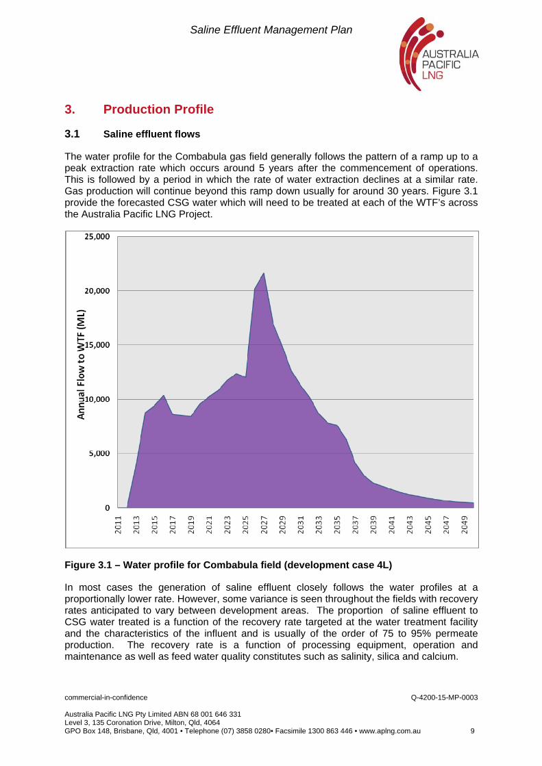
The water profile for the Combabula gas field generally follows the pattern of a ramp up to a peak extraction rate which occurs around 5 years after the commencement of operations. This is followed by a period in which the rate of water extraction declines at a similar rate. Gas production will continue beyond this ramp down usually for around 30 years. Figure 3.1 provide the forecasted CSG water which will need to be treated at each of the WTF’s across the Australia Pacific LNG Project.
Figure 3.1 – Water profile for Combabula field (development case 4L)
In most cases the generation of saline effluent closely follows the water profiles at a proportionally lower rate. However, some variance is seen throughout the fields with recovery rates anticipated to vary between development areas. The proportion of saline effluent to CSG water treated is a function of the recovery rate targeted at the water treatment facility and the characteristics of the influent and is usually of the order of 75 to 95% permeate production. The recovery rate is a function of processing equipment, operation and maintenance as well as feed water quality constitutes such as salinity, silica and calcium.
Saline Effluent Management Plan
commercial-in-confidence Q-4200-15-MP-0003 Australia Pacific LNG Pty Limited ABN 68 001 646 331 Level 3, 135 Coronation Drive, Milton, Qld, 4064 GPO Box 148, Brisbane, Qld, 4001 • Telephone (07) 3858 0280• Facsimile 1300 863 446 • www.aplng.com.au 10
The following table shows the WTFs that will be developed over the first 5 years of the project and their treatment capacity, anticipated recovery rate and forecast maximum saline effluent flow.
Table 3.1 - Details for Reedy Creek WTF recovery
Site Permanent Capacity
Predicted Recovery Rate
Maximum saline effluent flow rate
ML/d ML/d
Reedy Creek WTF 40 75% 14.8
Further details on the WTF’s including beneficial reuse of treated water can be found in the CSG Water Management Plan Section 4.
3.2 Low pH effluent
Along with saline effluent flows, a separate effluent stream consisting mainly of the backwash and regeneration fluids from the ion exchange process and membrane cleaning processes will be generated at each WTF site. This small effluent stream, high in ions other than sodium, will be neutralised by blending a small amount of the higher pH feed and sent to a dedicated compartment within the brine ponds to avoid mixing different contaminants with the other salts. This ensures that recovery opportunities from the bulk salts crystallised in the ponds are not jeopardised by the inclusion of more impurities in the form of calcium and magnesium salts than necessary. Once neutralised, this stream will be have similar or lower salinity to the main saline effluent stream and will be crystallised separately for disposal to licensed landfill facility. The dedicated pond for this stream will be of a similar standard of construction to the brine ponds.
3.3 Saline effluent characteristics
Saline effluent produced at each WTF will vary in both constituent salts and total dissolved salt concentration based on both the native characteristics of the CSG water being treated, and the design and operational parameters of that facility. The dominant salts in the CSG water differ between fields between sodium chloride (NaCl) and sodium carbonate or soda ash (Na2CO3) and sodium bicarbonate (NaHCO3). There are also significant amounts of fluoride, boron and generally high pH.
Estimated characteristics of the saline effluent to be generated at the WTF’s is as detailed in Table 3.2.

Saline Effluent Management Plan
commercial-in-confidence Q-4200-15-MP-0003 Australia Pacific LNG Pty Limited ABN 68 001 646 331 Level 3, 135 Coronation Drive, Milton, Qld, 4064 GPO Box 148, Brisbane, Qld, 4001 • Telephone (07) 3858 0280• Facsimile 1300 863 446 • www.aplng.com.au 11
Table 3.2 - Anticipated saline effluent characteristics
Property Units Value
pH 8.8
Temperature oC 15 - 30
Total Dissolved Salts mg/L 31,200
Suspended Solids mg/L <5
Dissolved Organic Carbon mg/L < 40
Silica as SiO2 mg/L 130
Calcium as Ca mg/L 4.0
Magnesium as Mg mg/L 4.0
Sodium as Na mg/L 11,300
Potassium as K mg/L 77
Barium as Ba mg/L 5.5
Strontium as Sr mg/L 17.5
Chloride mg/L 15,350
Carbonate as CaCO3 mg/L 300
Bicarbonate as CaCO3 mg/L 3,800
Fluoride by ISE mg/L 5.0
Boron as B mg/L 1.2
Sulphate as SO4 mg/L <1
Iron; total mg/L <0.5
Manganese; total mg/L <0.05
Aluminium; total mg/L <0.5
Anticipated CSG water composition at the Reedy Creek WTF, which in turn determines the composition of the saline effluent, is regarded as being typical of CSG water from wells in the northern project area such as the feed to the existing Spring Gully WTF. The expected ionic composition of the Reedy Creek CSG water shows a dominance of chloride salts.
3.4 Saline effluent profile
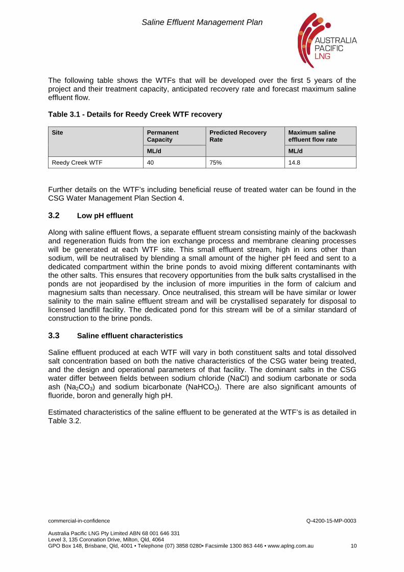
For the Reedy Creek WTF, a predicted 5.5 GL of saline effluent will be produced over the first 3 years of production (2013-2015). Whilst the flow of CSG water to Reedy Creek WTF will be lower than for other development areas, the flow of saline effluent will be similar. This is due to the anticipated recovery rate for this WTF of 75% being substantially lower those other sites. In other words, for a given volume of water treated through the Reedy Creek facility, a greater volume will be rejected as brine when compared to other sites (refer Table 3.2).
Figure 3.2 below shows the saline effluent to be generated across the Project for the first 3 years at Reedy Creek.
Saline Effluent Management Plan
commercial-in-confidence Q-4200-15-MP-0003 Australia Pacific LNG Pty Limited ABN 68 001 646 331 Level 3, 135 Coronation Drive, Milton, Qld, 4064 GPO Box 148, Brisbane, Qld, 4001 • Telephone (07) 3858 0280• Facsimile 1300 863 446 • www.aplng.com.au 12
Figure 3.2 - Saline effluent profile
3.5 Salt profile
The total mass of solids that could potentially be recovered from the Combabula development area is approximately 88,000 tonnes over the first 3 years of production (2013 to 2015). This is based on an assumption that the salinity of CSG water from this field would average 4,000 mg/L and that negligible salinity would remain in the treated water from the facility.
Saline Effluent Management Plan
commercial-in-confidence Q-4200-15-MP-0003 Australia Pacific LNG Pty Limited ABN 68 001 646 331 Level 3, 135 Coronation Drive, Milton, Qld, 4064 GPO Box 148, Brisbane, Qld, 4001 • Telephone (07) 3858 0280• Facsimile 1300 863 446 • www.aplng.com.au 13
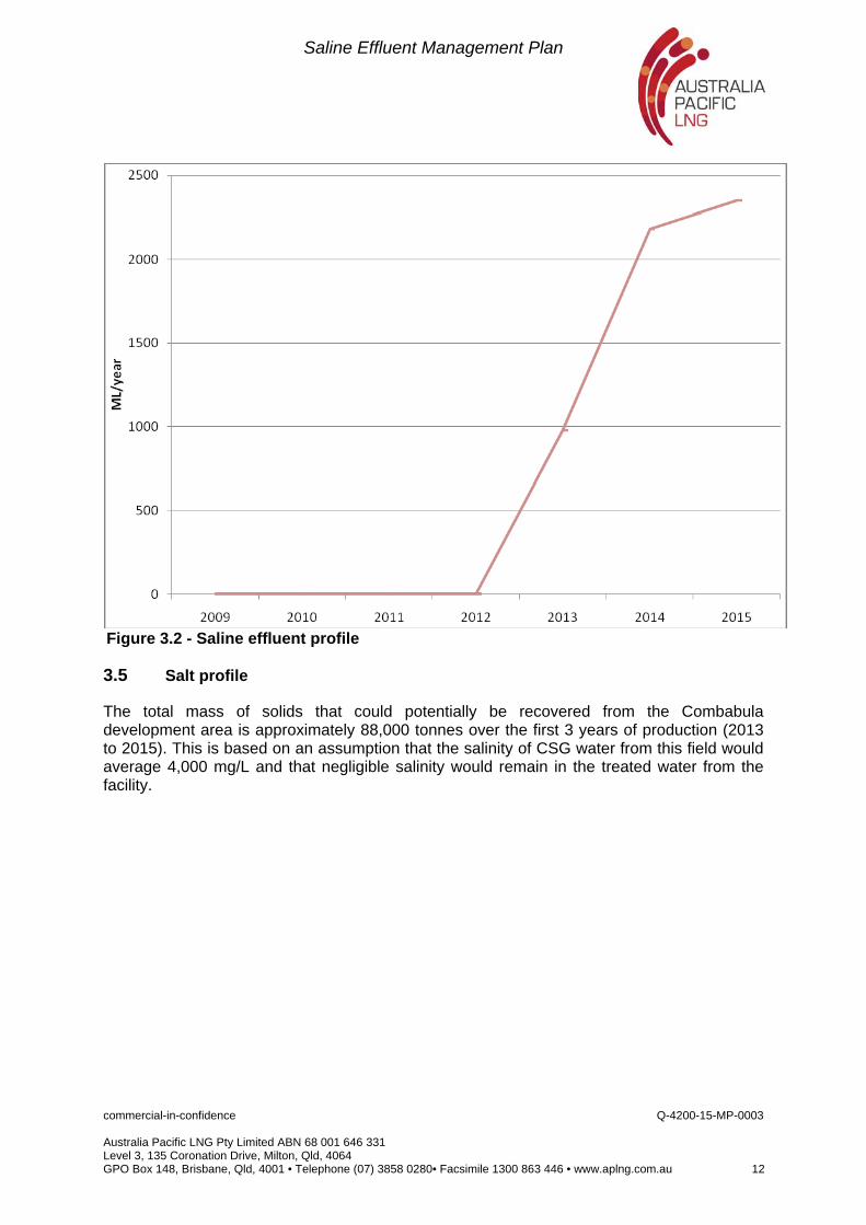
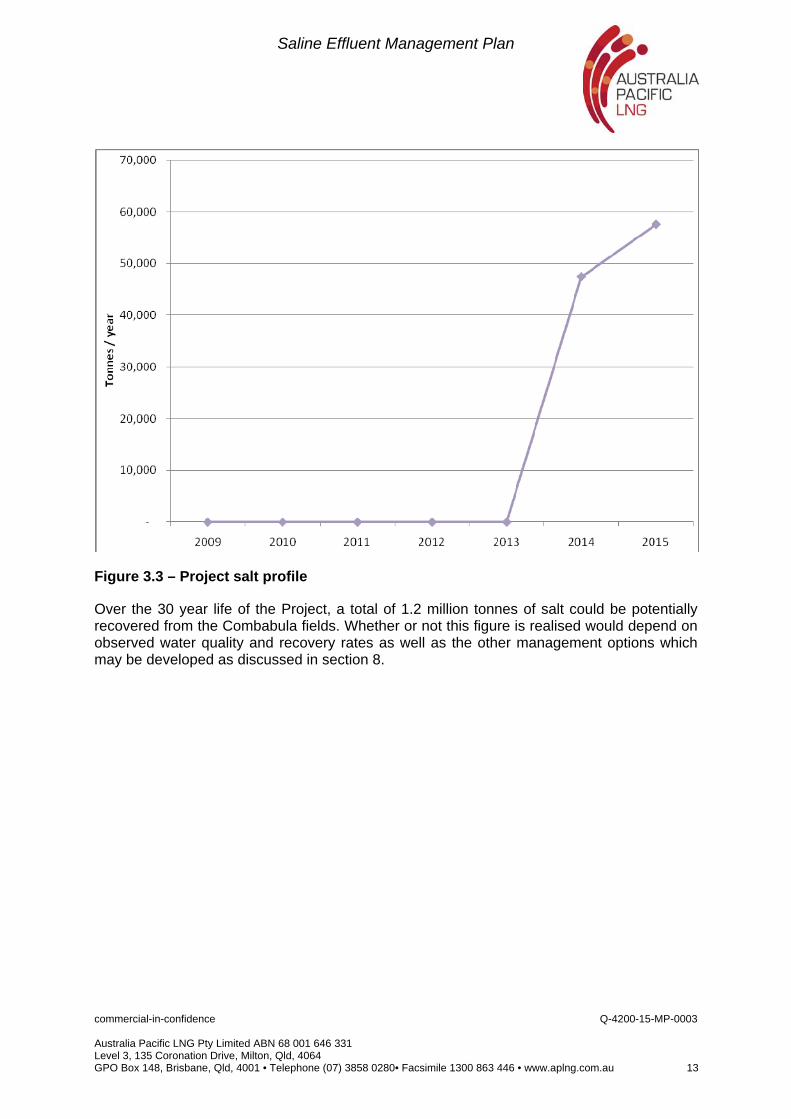
Figure 3.3 – Project salt profile
Over the 30 year life of the Project, a total of 1.2 million tonnes of salt could be potentially recovered from the Combabula fields. Whether or not this figure is realised would depend on observed water quality and recovery rates as well as the other management options which may be developed as discussed in section 8.
Saline Effluent Management Plan
commercial-in-confidence Q-4200-15-MP-0003 Australia Pacific LNG Pty Limited ABN 68 001 646 331 Level 3, 135 Coronation Drive, Milton, Qld, 4064 GPO Box 148, Brisbane, Qld, 4001 • Telephone (07) 3858 0280• Facsimile 1300 863 446 • www.aplng.com.au 14
4. Saline Effluent Management Approach
Australia Pacific LNG has committed to find the highest and best use of CSG water produced, including treatment by products, on a case by case basis. Lead by extensive research, Australia Pacific LNG has adopted a parallel approach to CSG water management. This approach has been developed to address uncertainties of water supply - demand, legislation, technology and commercial arrangements and includes the management of both treated water and saline effluent streams.
The approach delineates between “base case” options and “optimisation” options.
Base case options, to be adopted on a site by site basis, provide a sustainable management solution that can be readily applied using existing technologies and customers. In parallel Australia Pacific LNG will be developing a number of options, referred to as “optimisation” options. These will also be adopted on a site by site basis and their adoption will be in sequence of the respective site’s development. Uncertainties regarding salt quality and quantity, demand and supply are considered to diminish over time. The optimisation options are considered to provide potential further benefit once technology, negotiations and legislation have evolved.
4.1 Option selection
As discussed in detail in the Australia Pacific LNG EIS, a five step rational decision model was adopted for the appraisal and selection of the base case CSG water management options and subsequently included those for saline effluent. The model was used to define requirements, guide brainstorming and external investigative processes to develop management ideas, evaluate issues using two recognised management processes and result in the final saline effluent base case selection.
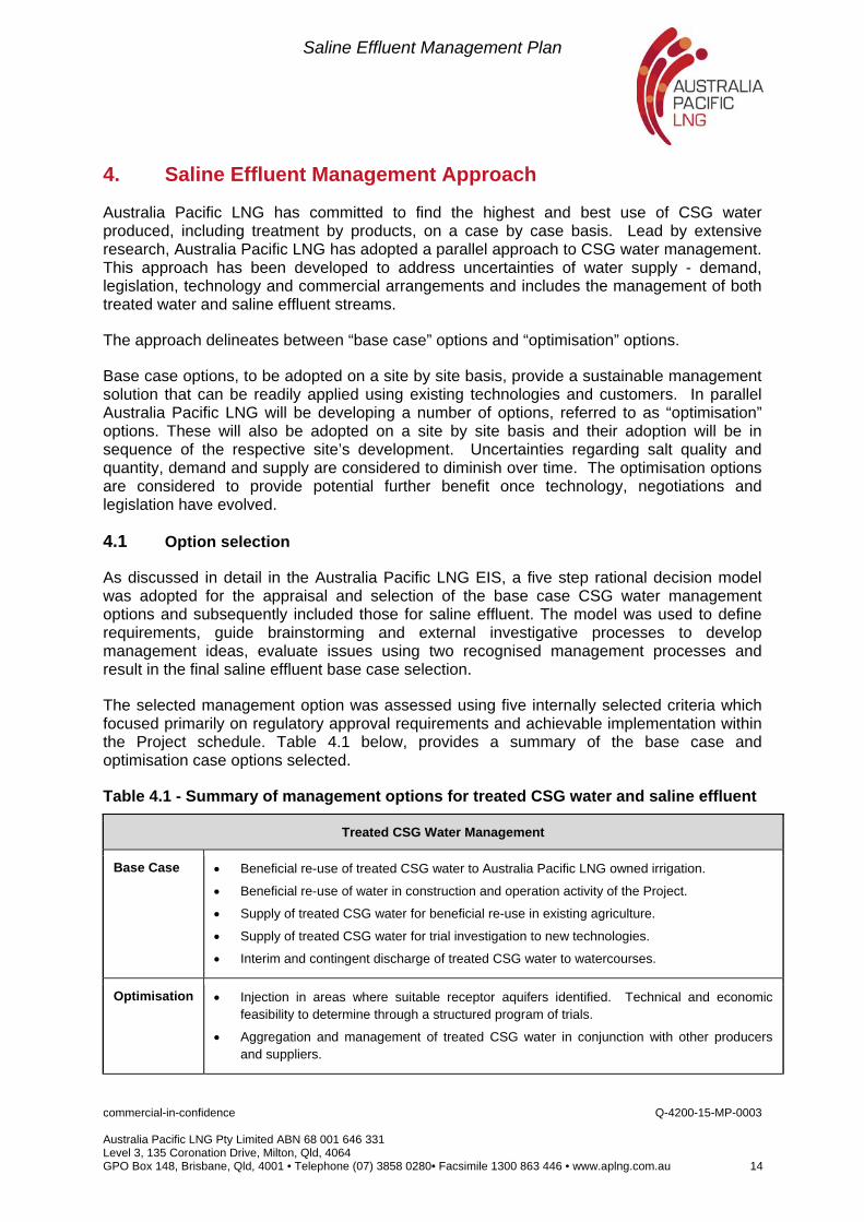
The selected management option was assessed using five internally selected criteria which focused primarily on regulatory approval requirements and achievable implementation within the Project schedule. Table 4.1 below, provides a summary of the base case and optimisation case options selected.
Table 4.1 - Summary of management options for treated CSG water and saline effluent
Treated CSG Water Management
Base Case Beneficial re-use of treated CSG water to Australia Pacific LNG owned irrigation.
Beneficial re-use of water in construction and operation activity of the Project.
Supply of treated CSG water for beneficial re-use in existing agriculture.
Supply of treated CSG water for trial investigation to new technologies.
Interim and contingent discharge of treated CSG water to watercourses.
Optimisation Injection in areas where suitable receptor aquifers identified. Technical and economic feasibility to determine through a structured program of trials.
Aggregation and management of treated CSG water in conjunction with other producers and suppliers.
Saline Effluent Management Plan
commercial-in-confidence Q-4200-15-MP-0003 Australia Pacific LNG Pty Limited ABN 68 001 646 331 Level 3, 135 Coronation Drive, Milton, Qld, 4064 GPO Box 148, Brisbane, Qld, 4001 • Telephone (07) 3858 0280• Facsimile 1300 863 446 • www.aplng.com.au 15
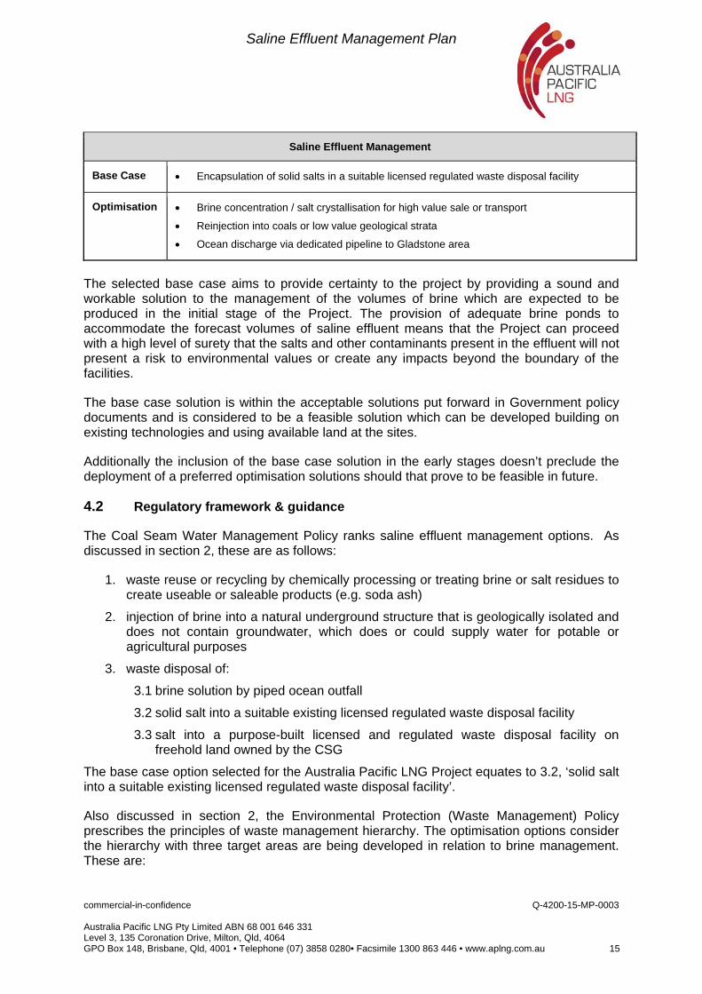
Saline Effluent Management
Base Case Encapsulation of solid salts in a suitable licensed regulated waste disposal facility
Optimisation Brine concentration / salt crystallisation for high value sale or transport
Reinjection into coals or low value geological strata
Ocean discharge via dedicated pipeline to Gladstone area
The selected base case aims to provide certainty to the project by providing a sound and workable solution to the management of the volumes of brine which are expected to be produced in the initial stage of the Project. The provision of adequate brine ponds to accommodate the forecast volumes of saline effluent means that the Project can proceed with a high level of surety that the salts and other contaminants present in the effluent will not present a risk to environmental values or create any impacts beyond the boundary of the facilities.
The base case solution is within the acceptable solutions put forward in Government policy documents and is considered to be a feasible solution which can be developed building on existing technologies and using available land at the sites.
Additionally the inclusion of the base case solution in the early stages doesn’t preclude the deployment of a preferred optimisation solutions should that prove to be feasible in future.
4.2 Regulatory framework & guidance
The Coal Seam Water Management Policy ranks saline effluent management options. As discussed in section 2, these are as follows:
1. waste reuse or recycling by chemically processing or treating brine or salt residues to create useable or saleable products (e.g. soda ash)
2. injection of brine into a natural underground structure that is geologically isolated and does not contain groundwater, which does or could supply water for potable or agricultural purposes
3. waste disposal of:
3.1 brine solution by piped ocean outfall
3.2 solid salt into a suitable existing licensed regulated waste disposal facility
3.3 salt into a purpose-built licensed and regulated waste disposal facility on freehold land owned by the CSG
The base case option selected for the Australia Pacific LNG Project equates to 3.2, ‘solid salt into a suitable existing licensed regulated waste disposal facility’.
Also discussed in section 2, the Environmental Protection (Waste Management) Policy prescribes the principles of waste management hierarchy. The optimisation options consider the hierarchy with three target areas are being developed in relation to brine management. These are:
Saline Effluent Management Plan
commercial-in-confidence Q-4200-15-MP-0003 Australia Pacific LNG Pty Limited ABN 68 001 646 331 Level 3, 135 Coronation Drive, Milton, Qld, 4064 GPO Box 148, Brisbane, Qld, 4001 • Telephone (07) 3858 0280• Facsimile 1300 863 446 • www.aplng.com.au 16
Reduce – brine concentration and crystallisation trials planned in 2011
Reuse – progressing negotiations with salt distributors, both halites (table salt) and
soda ash.
Recycle –studies continuing into the potential to inject brine into; the coal seam; the
basement formation; or depleted conventional fields.
Working within the waste hierarchy all three provide higher ranking options within the CSG Water Policy than the base case. Limitations exist however which reduce the potential to implement these potential solutions within the project timeframes.
Australia Pacific LNG seeks approval for base case options. Depending on option development, approval would be sought for optimisation options as an amendment to any existing EA.
4.3 Brine ponds
The base case for management of saline effluent generated for the Australia Pacific LNG Project is evaporation through the use of specifically designed brine ponds. These utilise the natural evaporation potential associated with the Central Queensland climate to further concentrate the saline effluent and crystallise the salts dissolved within it.
Benefits to the brine pond option are:
Reliability
Known technology and science
Potential for future salt recovery allowing for a lead time over which to develop market
Potential disadvantages to the brine pond option are:
Land requirements
Considerable capital costs for full scale development
Risk associated with failure to contain contents
The rated of evaporation is maximised by increasing surface area and subsequently an increasing area of disturbance. Brine pond dimension and staging are to consider both current and future demand and a balance between evaporation rate and land disturbance. The base case option to manage disposal of the salts resulting from the evaporation process, is the transfer of the solid salts to one or more third party licensed waste disposal contractors. Details on the solidification and removal of salts from the ponds are provided in section 6.4. Similarly, a third party- possibly the same party, would be responsible for the removal from site, transport to a suitable regulated waste facility and ongoing management of the disposal of waste salts at that facility. This option was developed as part of a study which considered the economic and environmental sustainability of a range of disposal solutions (Worley Parsons 2010b)
It is likely that a new waste facility will be required to be developed in the vicinity of the CSG fields servicing several WTF’s and potentially several CSG projects in the area. Origin Energy has been in contact with several established waste management companies to
Saline Effluent Management Plan
commercial-in-confidence Q-4200-15-MP-0003 Australia Pacific LNG Pty Limited ABN 68 001 646 331 Level 3, 135 Coronation Drive, Milton, Qld, 4064 GPO Box 148, Brisbane, Qld, 4001 • Telephone (07) 3858 0280• Facsimile 1300 863 446 • www.aplng.com.au 17
discuss future requirements and will progress this discussion to ensure that the appropriate facilities will be available. At least two potential locations have been discussed, though detailed siting studies would be required to confirm the suitability of the locations. Further detail on solid salt disposal is provided in section 7.
Saline Effluent Management Plan
commercial-in-confidence Q-4200-15-MP-0003 Australia Pacific LNG Pty Limited ABN 68 001 646 331 Level 3, 135 Coronation Drive, Milton, Qld, 4064 GPO Box 148, Brisbane, Qld, 4001 • Telephone (07) 3858 0280• Facsimile 1300 863 446 • www.aplng.com.au 18
5. Construction
5.1 Statutory regulations
5.1.1 General Statutory regulations
Brine ponds shall comply with the requirements of the Acts, Regulations, Rules, By-Laws and other requirements of the Australian and Queensland Governments, Local Governments and other Statutory Authorities. In particular, design for facilities shall meet the requirements of the Petroleum and Gas (Production and Safety) Act (2004) (PAG Act).
5.1.2 Requirements for hazardous dams
If a dam, pond or other water storage, operated under an environmental authority granted under the Environmental Protection Act 1994, contains hazardous waste, it will be nominated as a “referrable dam”, and will be governed by the provisions of that environmental authority. DERM guideline – Regulated dams in environmental activities, provides guidance on the requirements for approval of individual dams to be included in the environmental authourity. The related document Manual for Assessing Hazard Categories and Hydraulic Performance of Dams (currently in draft form – August 2010) gives detailed technical requirements for the design, certification and operation of regulated dams.
5.1.3 Hazard classification of ponds
The Manual for Assessing Hazard Categories and Hydraulic Performance of Dams outlines if the dam is considered to contain hazardous waste. It also provides guidelines for establishing whether a hazardous dam is classified as a significant or high hazard dam.
Under the manual, the contents of the ponds, base on quantity and salinity, all brine ponds will be at least significant. Upon application of a dam break analysis and a failure to contain analysis as prescribed by the manual to consider potential hazards associated with the brine ponds, the hazard category determined is high. The impact on downstream environmental values in the unlikely event of spillway release from a brine pond could be serious harm in many cases.
5.1.4 Pond design storage allowance requirements
The “Manual for Assessing Hazard Categories and Hydraulic Performance of Dams” requires that all regulated dams containing contaminants that could cause material or serious environmental harm must have a storage volume kept available in the pond to contain all inputs to the pond from foreseeable rainfall events in order to contain the contaminants and avoid such harm. That volume is the Design Storage Allowance (DSA) and must be available as at the first of November each year (start of the wet season).
In determining the DSA the ‘method of deciles’ was used in accordance with the draft “Manual for Assessing Hazard Categories and Hydraulic Performance of Dams”. As per the manual, net process flows were included for the duration of the wet period. For feed ponds the net process flows was assumed to be zero, as increments in capacity of the WTF will be scheduled to come online to always meet gathering system inflows. Process flows for brine
Saline Effluent Management Plan
commercial-in-confidence Q-4200-15-MP-0003 Australia Pacific LNG Pty Limited ABN 68 001 646 331 Level 3, 135 Coronation Drive, Milton, Qld, 4064 GPO Box 148, Brisbane, Qld, 4001 • Telephone (07) 3858 0280• Facsimile 1300 863 446 • www.aplng.com.au 19
and effluent ponds were consistent with predicted inflow rates and chemical discharges, respectively.
The pond Mandatory Reporting Level (MRL) shall be calculated as per the “Manual for Assessing Hazard Categories and Hydraulic Performance of Dams”. This is a level delineated in the ponds at which the design storage allowance has been substantially filled and will trigger immediate notification of the administering authority (DERM).
The MRL is calculated as the level at which either a 72 hour duration storm or a wind generated wave of 1 in 100 average recurrence interval could bring water levels to spillway level.
Detailed spillway calculations as per the “Manual for Assessing Hazard Categories and Hydraulic Performance of Dams” are to be determined during the detailed design stage. As high hazard dams, the spillways must be capable of safely discharging the flow from a design storm event with an annual exceedance probability of 1:50,000 years.
5.2 General design criteria
5.2.1 Design life of ponds
Design life for the brine, effluent and feed ponds are specified to be 20 years for design purposes, however the period for which ponds are required shall be determined on the progress of brine crystallisation and the actual water profile provided. Annual inspections will determine the asset condition of the ponds across their lifespan.
5.2.2 Siting of proposed brine ponds
Preliminary locations for the proposed future brine ponds have been identified, however further detailed assessment needs to occur to ensure that ponds are located in the most suitable location with minimal impacts. Consideration must be given to a range of factors when siting the ponds such as:
Existing vegetation: ponds must be sited such that minimal removal of remnant ecosystem occurs. Consideration must also be given to the risk of damage to sensitive ecosystems where failure of the bund walls or liner systems would result in damage to those ecosystems.
Visual amenity: ponds are to be located further than 400 m (for a low visual effect) from sensitive receptors such as houses and locations on tourist highways.
Land use: Minimise the loss of good quality agricultural land.
Ground water protection: where possible ponds are to be located away from areas where existing soils are pervious and could provide connection into local groundwater bodies.
Topography: Pond designs are to minimise required earthworks. Each site is to achieve, if possible, an earthworks cut and fill balance.
Flooding: Avoid placement of major infrastructure in existing flood extents and project infrastructure over tributaries and flow paths where practicable. Ponds will be located above
Saline Effluent Management Plan
commercial-in-confidence Q-4200-15-MP-0003 Australia Pacific LNG Pty Limited ABN 68 001 646 331 Level 3, 135 Coronation Drive, Milton, Qld, 4064 GPO Box 148, Brisbane, Qld, 4001 • Telephone (07) 3858 0280• Facsimile 1300 863 446 • www.aplng.com.au 20
the 100 year flood level and toe of pond batters to be a minimum 1m above the 1 in 100 AEP flood.
Site boundaries : consideration of downstream impacts on adjoining properties may determine that ponds be located with a significant buffer from downslope property boundaries.
Safety: Manage potential impacts of bund failure by appropriate location selection to minimise the potential for impact on residences and plant.
Proximity: Feed, effluent and brine transfer ponds / tanks (where required) are to be located where practicably possible adjacent to the corresponding WTF.
Groundwater: Groundwater level should be a minimum 1m beneath pond base.
Saline Effluent Management Plan
commercial-in-confidence Q-4200-15-MP-0003 Australia Pacific LNG Pty Limited ABN 68 001 646 331 Level 3, 135 Coronation Drive, Milton, Qld, 4064 GPO Box 148, Brisbane, Qld, 4001 • Telephone (07) 3858 0280• Facsimile 1300 863 446 • www.aplng.com.au 21
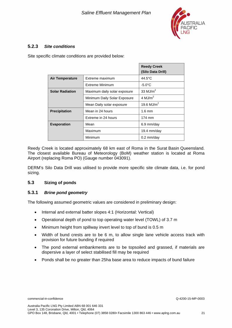
5.2.3 Site conditions
Site specific climate conditions are provided below:
Reedy Creek
(Silo Data Drill)
Air Temperature Extreme maximum 44.5°C
Extreme Minimum -5.0°C
Solar Radiation Maximum daily solar exposure 33 MJ/m2
Minimum Daily Solar Exposure 4 MJ/m2
Mean Daily solar exposure 19.6 MJ/m2
Precipitation Mean in 24 hours 1.6 mm
Extreme in 24 hours 174 mm
Evaporation Mean 6.9 mm/day
Maximum 19.4 mm/day
Minimum 0.2 mm/day
Reedy Creek is located approximately 68 km east of Roma in the Surat Basin Queensland. The closest available Bureau of Meteorology (BoM) weather station is located at Roma Airport (replacing Roma PO) (Gauge number 043091).
DERM’s Silo Data Drill was utilised to provide more specific site climate data, i.e. for pond sizing.
5.3 Sizing of ponds
5.3.1 Brine pond geometry
The following assumed geometric values are considered in preliminary design:
Internal and external batter slopes 4:1 (Horizontal: Vertical)
Operational depth of pond to top operating water level (TOWL) of 3.7 m
Minimum height from spillway invert level to top of bund is 0.5 m
Width of bund crests are to be 6 m, to allow single lane vehicle access track with provision for future bunding if required
The pond external embankments are to be topsoiled and grassed, if materials are dispersive a layer of select stabilised fill may be required
Ponds shall be no greater than 25ha base area to reduce impacts of bund failure

Saline Effluent Management Plan
commercial-in-confidence Q-4200-15-MP-0003 Australia Pacific LNG Pty Limited ABN 68 001 646 331 Level 3, 135 Coronation Drive, Milton, Qld, 4064 GPO Box 148, Brisbane, Qld, 4001 • Telephone (07) 3858 0280• Facsimile 1300 863 446 • www.aplng.com.au 22
5.3.2 Pondage requirements
A numerical model has been used to size all brine ponds by considering
Saline effluent flows from the WTF
Weather inputs to the system based on historical records
Concentration of salts as evaporation and ongoing inflow occurs
Expected evaporation rates from the pond as a response to these variables
This dynamic system is modelled on a daily time step to ensure that requirements for storage are met within a mandated probability which considers extreme wet weather events which could occur at a given frequency when considering historical weather observations.
The modelling process assumed ponds to be built in an incremental 20 ha pond size as mentioned above, as required in response to requirements for management of the saline effluent resulting from the treatment of forecast CSG water flows.
Weather data is sourced from the Silo enhanced meteorologic dataset to accurately represent the likely climate for the actual location of the proposed ponds. Evaporation from the dam is a function of not only the climatic conditions that occur on a given day in the modelled period but also the salinity of the stored water at that point in time. Due to the effect of dissolved ions on the water vapour pressure of a solution, as salinity increases, evaporation decreases relative to the evaporation expected from pure water.
The model is run to simulate the performance of the pond over a 50 year period with repetitions being performed to utilise the whole available period of climate data looped from the last available data to the first where required to provide unique, continuous 50 year periods.
Pond requirements are optimised through the modelling process by selecting the minimum number of ponds at the start of each year required to contain the saline effluent without exceeding the defined top operating water level for that year.
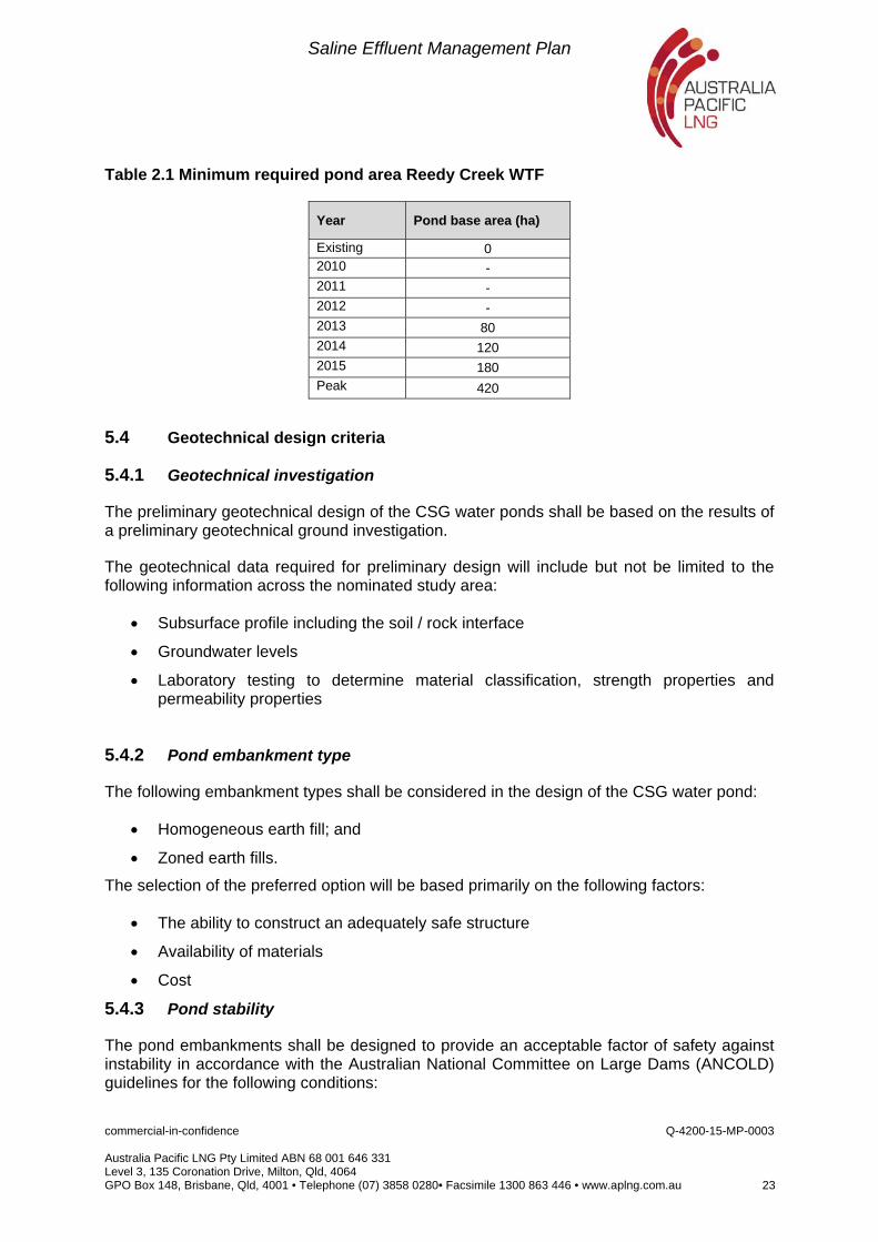
At Reedy Creek an area of 180 Ha of ponds will be constructed in the first 3 years of the WTF operation (2013 to 2015) with an ultimate 420 ha required by 2020.
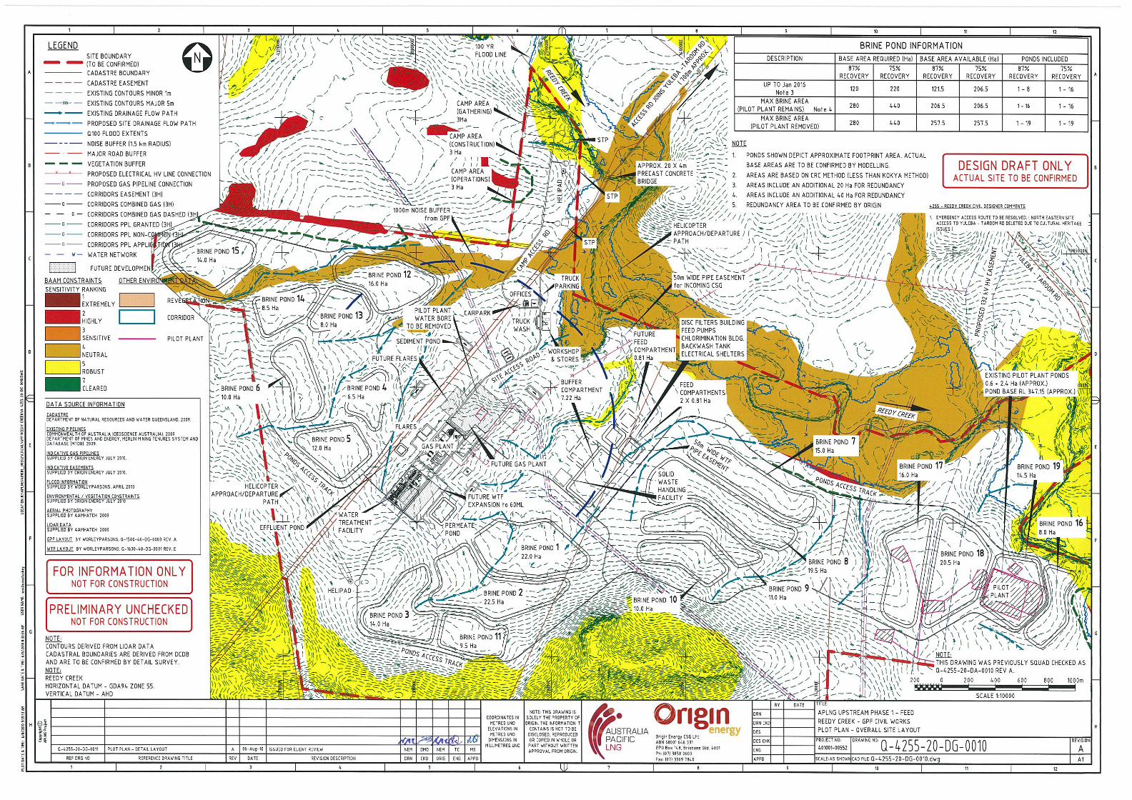
A plan showing the preliminary locations for ponds at Reedy Creek is shown at Appendix A.
Table 2.1 below, provides the current schedule of works for brine ponds for the APLNG Project. These predicted capacities are based on the water profile development 4i.
Saline Effluent Management Plan
commercial-in-confidence Q-4200-15-MP-0003 Australia Pacific LNG Pty Limited ABN 68 001 646 331 Level 3, 135 Coronation Drive, Milton, Qld, 4064 GPO Box 148, Brisbane, Qld, 4001 • Telephone (07) 3858 0280• Facsimile 1300 863 446 • www.aplng.com.au 23
Table 2.1 Minimum required pond area Reedy Creek WTF
Year Pond base area (ha)
Existing 0 2010 - 2011 - 2012 - 2013 80 2014 120 2015 180 Peak 420
5.4 Geotechnical design criteria
5.4.1 Geotechnical investigation
The preliminary geotechnical design of the CSG water ponds shall be based on the results of a preliminary geotechnical ground investigation.
The geotechnical data required for preliminary design will include but not be limited to the following information across the nominated study area:
Subsurface profile including the soil / rock interface
Groundwater levels
Laboratory testing to determine material classification, strength properties and permeability properties
5.4.2 Pond embankment type
The following embankment types shall be considered in the design of the CSG water pond:
Homogeneous earth fill; and
Zoned earth fills.
The selection of the preferred option will be based primarily on the following factors:
The ability to construct an adequately safe structure
Availability of materials
Cost
5.4.3 Pond stability
The pond embankments shall be designed to provide an acceptable factor of safety against instability in accordance with the Australian National Committee on Large Dams (ANCOLD) guidelines for the following conditions:
Saline Effluent Management Plan
commercial-in-confidence Q-4200-15-MP-0003 Australia Pacific LNG Pty Limited ABN 68 001 646 331 Level 3, 135 Coronation Drive, Milton, Qld, 4064 GPO Box 148, Brisbane, Qld, 4001 • Telephone (07) 3858 0280• Facsimile 1300 863 446 • www.aplng.com.au 24
Steady state seepage at full reservoir level:
End of construction conditions;
Rapid drawdown; and
Maximum Design Earthquake events.
5.5 Seepage containment system
Saline effluent could potentially be released to land and groundwater in the vicinity of the ponds via seepage through the floor and walls. This would present a significant environmental hazard given the potential negative impacts associated with the saline waters on nearby agricultural activities, groundwater dependent ecosystems and extractors of downstream groundwater. The current State policy for CSG Water Management states that all ponds containing both CSG water and saline effluent are required to be “fully lined to a standard determined by DERM”. A liner of very low permeability is critical to ensure that seepage from the pond system and hence negative environmental impacts are minimised.
Features of the liner to be specified will include:
UV protection
Maximum permeability of liner 10-12 m/sec (based on the ASTM test method D4716)
Double wedge weld joints for the main liner joints to reduce leakage through the joints. Joints are to be pressure tested during installation
To provide additional protection to the liner, a layer of BIDIM A34 geotextile or equivalent to be placed beneath the liner.
The liner design that will be employed for Australia Pacific LNG brine ponds will vary between sites depending on key variables such as the existing hydrogeological characteristics of the strata directly beneath the pond and the availability of suitable clay materials in the vicinity of the site.
In many cases and given suitable pre-treatment, in situ materials in the footprint of the ponds will provide part of the barrier preventing any seepage from the pond progressing into surrounding land and groundwater. In other cases the existing soils may present a risk that any seepage could be transported from the pond more rapidly and hence the liner design needs to incorporate a higher level of protection from seepage.
Australia Pacific LNG has recently, October 2010, commissioned a feasibility study for the selection of brine pond liner systems. The study’s findings, including risk and cost assessments are due in early 2011, and will provide further clarity in liner system selection. At present Australia Pacific LNG are proceeding in detail design with as base case design system that has been indicatively assessed to be compliant with regulatory guidance.
The current base case liner system to be deployed consists of a dual layer with intermediate drainage. A highly impermeable 2 mm thick high density polyethylene (HDPE) geomembrane layer forms the uppermost layer and whilst intact will prevent any loss of stored effluent. As a contingency in case of a leak developing in the primary HDPE liner, a secondary liner is laid underneath. The secondary liner will consist of a specially formulated
Saline Effluent Management Plan
commercial-in-confidence Q-4200-15-MP-0003 Australia Pacific LNG Pty Limited ABN 68 001 646 331 Level 3, 135 Coronation Drive, Milton, Qld, 4064 GPO Box 148, Brisbane, Qld, 4001 • Telephone (07) 3858 0280• Facsimile 1300 863 446 • www.aplng.com.au 25
geosynthetic clay liner (GCL) which is essentially an engineered clay substance matched to be compatible with the stored effluent, sandwiched between two layers of geotextile.
In order that any leakage from the primary layer is detected and removed before it can build up a pressure on the secondary layer, a drainage network is to be incorporated. The drainage layer is formed by a layer of structured plastic drainage product which is intersected by a network of graded slotted pipe bedded in coarse sand. This network will collect and centralise any effluent that enters the drainage system to a pumping sump from where it can be returned to the pond.
5.6 Windborne salt containment
In the design of the saline effluent management system, consideration has been given to the minimisation of salinity impacts which could result from windborne particles being carried beyond the ponds. Pond embankments which are adequately high to cater for design storage allowance and spillway freeboards are deemed to be adequate to contain any airborne particles which are generated by the action of wind driven waves on the sides of the ponds. This will verified by the observation of vegetation health surrounding the ponds and groundwater quality in the surrounding monitoring bores. No additional agitation of pond contents is proposed.
5.7 General civil design criteria
5.7.1 Sediment and erosion control
The construction of the proposed ponds associated with the water treatment facilities shall ensure that erosion control devices and sediment traps shall be installed to minimise the potential of sediment entering the existing waterway system.
Erosion control measures shall meet EIS commitments and be based on industry best management practices for construction site soil erosion and sedimentation control. This may include the implementation of measures as specified in “Soil Erosion and Sediment Control – Engineering Guidelines for Queensland Construction Sites” Institution of Engineers Australia (Queensland Division 1996) and Department of Environment and Resource Management - Erosion Control.
5.8 Safety in design
Brine ponds incorporate a number of safety features which are fundamental to the design. Bund walls are kept to a minimum height and as a result the stability of the bunds are maximised and implications should the bund fail are reduced due to the lower height of the flood wave which could potentially result.
Upper plastic liners on the walls of the ponds are specified to be textured to reduce the risk of personnel or errant animals slipping into the stored effluent. The ponds are also equipped with rope ladders extending from the crest into the stored effluent at multiple locations on the bund to enable emergency egress in the case of accidental pond entry.
Saline Effluent Management Plan
commercial-in-confidence Q-4200-15-MP-0003 Australia Pacific LNG Pty Limited ABN 68 001 646 331 Level 3, 135 Coronation Drive, Milton, Qld, 4064 GPO Box 148, Brisbane, Qld, 4001 • Telephone (07) 3858 0280• Facsimile 1300 863 446 • www.aplng.com.au 26
Security fencing will extend around the perimeter of all ponds to exclude members of the public, stock and wildlife from the ponds. A galvanised hexagonal netting of 600 mm width (450 mm exposed and 150 mm buried) will be installed at the bottom of the fencing to stop any burrowing by animals.
Saline Effluent Management Plan
commercial-in-confidence Q-4200-15-MP-0003 Australia Pacific LNG Pty Limited ABN 68 001 646 331 Level 3, 135 Coronation Drive, Milton, Qld, 4064 GPO Box 148, Brisbane, Qld, 4001 • Telephone (07) 3858 0280• Facsimile 1300 863 446 • www.aplng.com.au 27
6. Operation
6.1 Operating philosophies
The saline effluent will initially be discharged from WTF’s is distributed to all ponds equally. This allows the maximisation of surface area and hence evaporation. The maximum volume of stored brine at each WTF will be reached around 4 to 12 years into the Project depending on the field being served by the WTF. At the point when flows begin to subside, partially evaporated saline effluent can then be consolidated in fewer and fewer ponds and emptied ponds can be flushed and decommissioned.
Concentrated brine will eventually remain in the specially equipped crystallisation pond which would allow full crystallisation to proceed and windrowing followed by removal of the solids.
6.2 Leak detection
Under the current State policy, ponds containing CSG water or saline effluent must “have a system to detect any passage of the wetting front or entrained contaminants through either the floor or sides of the dam”. Additionally, “The system implemented to detect the passage of the wetting front through either the floor or sides of the dam must consist of more than just monitoring groundwater aquifers” (DERM June 2010).
Australia Pacific LNG are currently undertaking a study to determine the optimal system for leak detection. The system for leak detection adopted for Australia Pacific LNG’s recently constructed brine ponds is a geoelectric detection system which uses a pair of probes, one in the stored liquid and one in the surrounding soil, to measure the electric resistivity across the pond liner to detect flaws in the liner which allow the passage of saline effluent. This system is installed at the construction stage and remains active for the life of the pond such that the development of a leak would be detected soon after its occurrence.
Another system being implemented relies on a drainage system which is installed underneath the primary liner of the pond, as detailed in section 5.6. The rate of flow detected in the drainage system provides an indication of the amount of leakage that is occurring from the primary liner. Collection and removal of this flow for return to the pond ensures that the secondary liner will be subjected to minimal water pressures and is unlikely to develop any substantial leaks.
Details of the remedial action to be enacted following the detection of leaks are provided in section 10.1.
Saline Effluent Management Plan
commercial-in-confidence Q-4200-15-MP-0003 Australia Pacific LNG Pty Limited ABN 68 001 646 331 Level 3, 135 Coronation Drive, Milton, Qld, 4064 GPO Box 148, Brisbane, Qld, 4001 • Telephone (07) 3858 0280• Facsimile 1300 863 446 • www.aplng.com.au 28
6.3 Instrumentation
Instrumentation for the brine ponds will include but not be limited to the following:
Level gauges within all ponds to allow assessment of water level across the potential range and to identify the Mandatory Reporting Level and Spillway Level;
Downstream groundwater monitoring bores;
Level gauges and pump runtime meters on the drainage network collection sump to allow monitoring of volumes of any seepage which passes the primary liner to be collected by the secondary liner; and
Standpipe piezometers installed through the pond embankment to detect any moisture buildup in the embankment.
Monitoring boreholes are installed to assess the impact of the ponds on the local hydro-geological environment by;
Confirming potential pathways for any contamination from facilities,
Collecting baseline information on groundwater levels and groundwater quality,
Providing facilities for ongoing monitoring of groundwater levels and quality during operation of the ponds.
Further information on the groundwater monitoring program can be found in section 11.2.
6.4 Solidification
Solar evaporation forms the primary method for brine concentration. The process involves utilisation of available net evaporation to reduce the volume of water in the containment ponds. The design area for each containment pond is matched to weather data and water inflow rates. Other factors are used to adapt the water pan evaporation data for use in brine evaporation calculations. Evaporation to dryness involves initial concentration of brine in order for the solution to reach saturation and then crystallising the salts from this saturated brine solution.
Progressive concentration of brine containing mixed salts results in these different salts crystallising out of solution over ranges of concentrations. This process is driven by the relative solubility of each of the salts and interactions between different ions in the solution. The proposed containment pond design allows for the salts to remain in solution over the majority of the life of the Project.
The containment ponds are all filled uniformly and therefore operate at similar brine densities over time. The end of life deposition of precipitated salt will result in even distribution in each of the containment ponds. As the brine flow reduces through the latter part of the Project life, the brines will concentrate to the point where crystallisation of salts will commence. The deposition of crystalline mixed salts will continue for a number of years (4 - 6 years) as input brine flow ramps down and ceases.
Saline Effluent Management Plan
commercial-in-confidence Q-4200-15-MP-0003 Australia Pacific LNG Pty Limited ABN 68 001 646 331 Level 3, 135 Coronation Drive, Milton, Qld, 4064 GPO Box 148, Brisbane, Qld, 4001 • Telephone (07) 3858 0280• Facsimile 1300 863 446 • www.aplng.com.au 29
Towards the final stages of evaporation, the more soluble salts (Magnesium Chloride and Potassium Chloride) will concentrate in solution. The bitterns should be removed from the surface of the deposited salt during the crystallisation process by pumping from a sump.
Bitterns are effective and widely used commercially for dust suppression or further harvested for epsom salts (magnesium sulphate), a soil additive. As the quantity of bitterns is minimal (-50ML over 4 - 6 years), managing and disposing is easily facilitated.
Salt precipitate will become dry but will generally retain some interstitial saturated brine. The excavated salt precipitate will be windrowed within the containment pond and allowed to drain prior to transport to landfill.
Saline Effluent Management Plan
commercial-in-confidence Q-4200-15-MP-0003 Australia Pacific LNG Pty Limited ABN 68 001 646 331 Level 3, 135 Coronation Drive, Milton, Qld, 4064 GPO Box 148, Brisbane, Qld, 4001 • Telephone (07) 3858 0280• Facsimile 1300 863 446 • www.aplng.com.au 30
7. Final Salt Disposal
It is assumed that given uncertainty in alternative reuse options, there will be a portion of salt residue or salt contaminated material which will require disposal.
Due to the potential for this waste to produce highly saline solution on contact with water, and subsequent environmental damage associated with failure to contain that solution, it will likely be classified as regulated waste and the appropriate controls will need to be put in place for its transport, transfer and disposal.
There will also be financial implications due to the State Government’s Industry Waste Levy.
In line with the waste management hierarchy which underpins the Environmental Protection (Waste Management) Policy/Regulation 2000, the volume of material sent for disposal is minimised through consideration of higher order strategies such as recycling.
7.1 Timeframe for disposal activities
Disposal of salt would commence from the point at which solid salt can be isolated through evaporation in ponds or enhanced crystallisation processes as discussed in section 8.2. Under the base case ponds are expected to reach significant solids contents after approximately 15 years. From this point onwards the solids would be progressively encapsulated in sealed landfill cells until no further solids are generated and the last of the brine ponds can be decommissioned.
7.2 Landfill development considerations
It is likely that a new facility will be required to be developed in the vicinity of the CSG fields servicing several WTF’s and potentially several CSG projects in the area.
Origin Energy on behalf of Australia Pacific LNG has been in contact with several established waste management companies to discuss future requirements and will progress this discussion to ensure that the appropriate facilities will be available.
Requirements for the landfill which would be required to sustainably contain waste salt will include as a minimum, complete encapsulation of the stored waste with a structurally suitable liner material of very low or negligible permeability. This liner material must exclude the ingress of rainfall, runoff or groundwater into the waste, and the egress of any fluids from the landfill cell into the environment.
Design of the final geometry of the cell would require a balance between shaping of the surface to match surrounding topography whilst maintaining adequate drainage from the surface so as to limit the potential for water to penetrate the top surface of the landfill. The bulk of the material would be stored below original ground levels and the height of the cell will be kept to a minimum. Consideration should be given to the potential for settlement to alter the final profile, although given the crystalline nature of the material, it is likely that a significant degree of compaction could be achieved in the placed material, limiting further consolidation.
Saline Effluent Management Plan
commercial-in-confidence Q-4200-15-MP-0003 Australia Pacific LNG Pty Limited ABN 68 001 646 331 Level 3, 135 Coronation Drive, Milton, Qld, 4064 GPO Box 148, Brisbane, Qld, 4001 • Telephone (07) 3858 0280• Facsimile 1300 863 446 • www.aplng.com.au 31
A comprehensive groundwater monitoring system would need to be implemented at the site to detect any possible release of material. The Australian Standard AS/NZS 5667.11:1998 provides guidance on the methods to be employed in designing and implementing a groundwater monitoring program.
An alternative option under consideration is for one or more dedicated landfill facilities to be developed within Australia Pacific LNG tenures.
This option would involve a commitment to monitor and maintain the landfill beyond the point where the solids generated by the Project have been encapsulated. Low level activities associated with management of the landfill would continue for many years beyond the decommissioning and rehabilitation of other infrastructure at the site. The site on which the landfill was located would likely remain as a contaminated site into the foreseeable future. This, however would be carried out under an additional approval and does not form part of the base case for the project.
7.3 Landfill location
Evaluation of landfill sites suggest that it is likely that the base case (i.e. encapsulation of all the mixed salt produced off-site) is a purpose-built landfill. Detailed siting studies would be required to confirm the suitability of the locations.
As a minimum, siting of any landfill would need to consider:
Potential for flooding
Land value of the area under the footprint of the cell from both a biodiversity
and agricultural land perspective
Proximity to boundaries with other properties
The closest operating regulated waste disposal facility in lpswich is approximately 300km from the Australia Pacific LNG CSG operations at Reedy Creek. It is proposed that the chosen site is owned and operated by a third party service provider. Various business/operational models are available for managing the waste.
In determining the optimum location for the landfill facility, a study will be undertaken assessing material handling issues including slurry/brine pipelines, trucking routes, and the placement of wastewater treatment facilities. Optimising the locations of the proposed facilities is will be progressed further during detailed design of the brine ponds. As previously mentioned, Origin Energy, on behalf of Australia Pacific LNG have been in contact with several established waste management companies to discuss future requirements and have identified two potential locations.
7.4 Transport to landfill
Given the salt production as estimated in section 3.4, the number of truck movements required to transport salt from the Reedy Creek site would be around two B Doubles per day every day during the decommissioning period.
Saline Effluent Management Plan
commercial-in-confidence Q-4200-15-MP-0003 Australia Pacific LNG Pty Limited ABN 68 001 646 331 Level 3, 135 Coronation Drive, Milton, Qld, 4064 GPO Box 148, Brisbane, Qld, 4001 • Telephone (07) 3858 0280• Facsimile 1300 863 446 • www.aplng.com.au 32
Transport of the salt waste would be undertaken using licenced waste transport contractors over the public road network and sealed all weather access roads within the sites.
Risks associated with this transport operation will addressed in as road safety analysis to be developed as part of the waste salt management plan.
Saline Effluent Management Plan
commercial-in-confidence Q-4200-15-MP-0003 Australia Pacific LNG Pty Limited ABN 68 001 646 331 Level 3, 135 Coronation Drive, Milton, Qld, 4064 GPO Box 148, Brisbane, Qld, 4001 • Telephone (07) 3858 0280• Facsimile 1300 863 446 • www.aplng.com.au 33
8. Brine Pond Decommissioning
There will be significant quantities of crystalline salt requiring disposal over the life of the Project. The final disposal option for these excess solids is encapsulation in a specially designed landfill facility. There could potentially be earthen and other liner materials which have been contaminated by salt and are unsuitable for recycling that will need to be disposed of as well.
Once taken offline, the brine ponds which are no longer required must be decommissioned in a manner which eliminates any ongoing environmental hazard, returning the land for future land uses and the scenic amenity to the area.
8.1 Rehabilitation
Once salt is removed brine ponds will need rehabilitation, as they are no longer necessary to remove any source of potential contaminants and return the land to a useable form. The objective for the rehabilitation process will be to return the area to a useable, stable land form from which does not contain contamination. The process for decommissioning of ponds will involve the following major components.
Remove synthetic liners:
Options for recycling of the liner materials such as a feed stock for a pyrolytic process for the production of liquid fuels are being identified.
Assess any land contamination which may have occurred:
In the case were some leakage of the liner system has occurred a full contaminated land assessment will be undertaken as per the National Environment Protection (Site Assessment) Measure 1999
Remediate soils:
Removal or insitu treatment of contaminated soils will be undertaken were required through the site assessment.
Retain clay materials:
Where clay has been used as part of the containment system, this would be stockpiled for reuse where appropriate or shaped and capped for revegetation.
Rehabilitate site:
The bunds would be removed and depressions filled to return landforms to match surrounding topography. Retained or imported topsoil will be placed to a minimum depth of 0.25 m and a revegetation program instigated.
Ongoing monitoring:
Groundwater monitoring at the brine pond sites will continue at an annual frequency for 5 years to ensure any undetected releases are not still moving through the groundwater. Frequency and duration of groundwater monitoring may be greater as determined by the
Saline Effluent Management Plan
commercial-in-confidence Q-4200-15-MP-0003 Australia Pacific LNG Pty Limited ABN 68 001 646 331 Level 3, 135 Coronation Drive, Milton, Qld, 4064 GPO Box 148, Brisbane, Qld, 4001 • Telephone (07) 3858 0280• Facsimile 1300 863 446 • www.aplng.com.au 34
site assessment. Annual assessment of revegetated areas will be carried out for 5 years to ensure establishment of replanting and that pest plants are not becoming established.
8.2 Timeframe for decommissioning of brine ponds
Brine pond decommissioning should proceed as soon as possible as the water production subsides and disused ponds come off line. Any residual environmental risk associated with the ponds is therefore minimised and the decommissioning and rehabilitation works can proceed in a staged fashion.
Modelling indicates that by 2024 the first ponds will become available for decommissioning at Reedy Creek.
Saline Effluent Management Plan
commercial-in-confidence Q-4200-15-MP-0003 Australia Pacific LNG Pty Limited ABN 68 001 646 331 Level 3, 135 Coronation Drive, Milton, Qld, 4064 GPO Box 148, Brisbane, Qld, 4001 • Telephone (07) 3858 0280• Facsimile 1300 863 446 • www.aplng.com.au 35
9. Continuous Improvement
Given adequate time for research and development, other options for the management of saline effluent may be determined to be feasible. These are being developed in parallel and are referred to as optimisation options. Where these options can demonstrate gains over the base case, they will be trialled and potentially implemented across the Project.
9.1 Brine concentration
More active methods of concentration and crystallisation which could either be used in place of or together with brine ponds are being investigated. Most of these methods require an input of thermal or electrical energy and there is an inherent cost and greenhouse gas implication for the Project. Active concentration presents opportunities to significantly reduce surface impacts through the construction of ponds. Controlled crystallisation processes would also allow the separation of the various salt species in solution in the effluent to allow value adding and or sale of the salt.
A number of processes for the concentration and crystallisation of the saline effluent are under investigation.
9.1.1 Selective salts recovery
Under this process the more valuable carbonate and bicarbonate salts will be recovered from the mixture of salts in the effluent stream. Through this process, the concentration of salts in the effluent stream is increased in a temperature controlled concentration process to cause particular salt species (Carbonates and Bicarbonates) to precipitate whilst leaving others in solution. The resultant chloride rich brine can then either be disposed or further crystallised to create additional selective products.
Benefits to Selective Salts Recovery are:
Value added process which capitalises on marketable compounds existing in the
effluent
Accounts for the volume of saline effluent produced without large areas required for
brine ponds
Potential disadvantages to selective salts recovery with liquid discharge are:
The cost and complexity of the process
The need to dispose the final effluent from this process
9.1.2 Selective salts recovery with zero liquid discharge
This process relies on complete crystallisation of all dissolved salts in the effluent. The water component is completely evaporated in the concentrator and evaporator process units. Some salt disposal to landfill may be required under this option.
Benefits Selective Salts Recovery with Zero Liquid Discharge are:
Saline Effluent Management Plan
commercial-in-confidence Q-4200-15-MP-0003 Australia Pacific LNG Pty Limited ABN 68 001 646 331 Level 3, 135 Coronation Drive, Milton, Qld, 4064 GPO Box 148, Brisbane, Qld, 4001 • Telephone (07) 3858 0280• Facsimile 1300 863 446 • www.aplng.com.au 36
The elimination of the liquid waste stream removes the requirement for either ponds
or a lengthy pipelines and the impacts and cost associated with these
Reuse of the majority of the salts available
Potential disadvantages to Selective Salts Recovery with Zero Liquid Discharge are:
High cost and complexity associated with concentration / crystalliser
Some disposal to landfill required
9.2 Commercial sale
A number of salts contained in CSG water have some commercial value. Due to the ready availability of sodium chloride from seawater sources, this will not be targeted for recovery; however carbonate and bicarbonate salts of sodium are more valuable. These salts are present in a crystalline product known as trona which can be extracted separately.
Investigations are ongoing into the feasibility of this process and the marketability of the resultant trona.
In addition to the extraction of dissolved salts from the saline effluent, some options for value adding to processes using saline byproducts as a feedstock have been investigated. One option considered is to use saline solutions in a chloralkalai process that produce products such as caustic, hydrogen and chlorine products. It is unlikely that all of the salts would be consumed in such a process due to the limited markets for such products but it may be combined with the extraction of trona to reduce the overall quantity of salt for disposal.
Benefits of commercial salts sale are:
The elimination of all or part of the solid waste stream
Potential for further value adding project opportunities
Potential disadvantages to commercial salts sales are:
Potential for uncertainty of market conditions for salt products
9.3 Reinjection
An optimisation option for saline effluent management is injection to geological storages that provide appropriate containment characteristics, and that have suitably low potential for adverse impacts on environmental or beneficial use values. This option involves identification of appropriate storages to accept saline effluent quality injectates. Regional hydrogeological targeting investigations have been undertaken, with the most prospective target to date being depleted CSG coals. Investigations into both the feasibility of reinjection to coal and the development of alternative targets are ongoing.
Benefits to the reinjection option are:
Long term stability – limited ongoing management post disposal
Saline Effluent Management Plan
commercial-in-confidence Q-4200-15-MP-0003 Australia Pacific LNG Pty Limited ABN 68 001 646 331 Level 3, 135 Coronation Drive, Milton, Qld, 4064 GPO Box 148, Brisbane, Qld, 4001 • Telephone (07) 3858 0280• Facsimile 1300 863 446 • www.aplng.com.au 37
Returns salts to a similar place from where they came
Surface level disturbance minimal
Comparably low energy
Potential disadvantages to the reinjection option are:
Availability of suitable formations
Need to establish the level of connectivity of target formation
Unlikely to satisfy all disposal requirements
9.4 Ocean disposal
Investigations are being undertaken to the disposal of brine to the ocean via a dedicated pipeline to Port Curtis at Gladstone. Based on an initial environmental risk assessment, this could be could be carried out over the Project period with minimal environmental impacts. This assertion would need to be tested through extensive dispersion modelling and ecological assessments for the receiving environment. As discussed in section 3.2, the saline effluent will consist mainly of sodium chloride and carbonates with lower quantities of a number of other inorganic constituents. However, given the recent experience with the development of seawater desalination plants, it is likely that community concerns regarding an ocean discharge would be strong.
The main pipeline would be approximately 450km long with spur lines running to several WTF’s and it would require significant elevation changes over the route. Some technical issues would need to be resolved regarding the pipeline but initial estimates suggest a feasible design and construction approach.
Access to a land corridor for the pipeline would need to be assured. There are some potential benefits to aligning the pipeline with the gas pipeline for much of its length though a comprehensive corridor selection study would still be required and new easements secured.
This proposal could be incorporated with salt recovery options where saline effluent is extracted downstream on the pipeline closer to industrial salt customers and downstream processors.
Benefits of the ocean release pipeline option are:
Removes salts from a location where they can potentially contaminate land and
ground water systems
Carbonate and bicarbonate content considered potentially beneficial for marine
ecosystems
Opportunities for collaboration with other CSG proponents
Potential disadvantages to the ocean release pipeline option are:
Potential for durability issues with pipeline material
Saline Effluent Management Plan
commercial-in-confidence Q-4200-15-MP-0003 Australia Pacific LNG Pty Limited ABN 68 001 646 331 Level 3, 135 Coronation Drive, Milton, Qld, 4064 GPO Box 148, Brisbane, Qld, 4001 • Telephone (07) 3858 0280• Facsimile 1300 863 446 • www.aplng.com.au 38
Lead time for securing pipeline corridor and construction
Community environmental concerns with ocean discharge
9.5 Solar ponds
The concept of solar ponds has recently been developed to use a significant temperature gradient forms in highly saline ponds when exposed to adequate solar warming. The temperature differential is used to drive a rankin cycle in which a heated fluid is used drive a turbine as it vaporises and is subsequently condensed back to a liquid.
This would provide a beneficial use for this waste stream providing a carbon neutral energy source from ponds
Specific areas requiring investigation are the management of ponds to maximise and maintain the thermal gradient which provides the driving force for the generation process. Variables of pond depth and salinity are thought to be significant factors. The temperatures that could be observed in this controlled system could lead to additional design considerations for the protection of liner systems under high temperature.
Australia Pacific LNG are investigating likely partners, to implement trials of the technology and its broader roll out is not expected to occur within the first 5 years of the Project.
9.6 Algae production
Algae production is being assessed as a potential beneficial use of brine ponds, whereby an algae production process is incorporated in to some the ponds for the purpose of biodiesel production. Synergies with the proposed evaporation ponds exist in that salinity stressing of algae can lead to higher oil yields. Harvested algae could be used to extract an oil product to replace petroleum hydrocarbon as a feedstock in a number of processes and the remaining biomass is potentially useable as animal feed.
There would likely need to be significant additional infrastructure required to harvest and process the algae and some process proposals include a transparent containment structure in which the algae is exposed to maximum light.
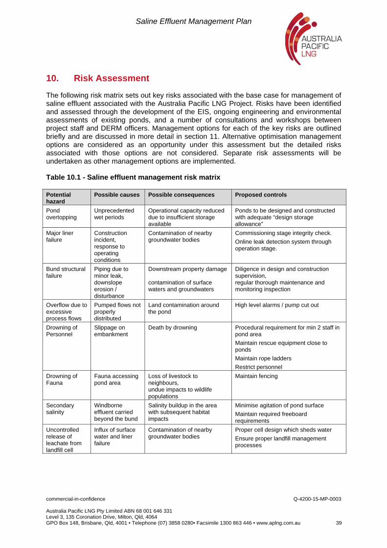
Saline Effluent Management Plan
commercial-in-confidence Q-4200-15-MP-0003 Australia Pacific LNG Pty Limited ABN 68 001 646 331 Level 3, 135 Coronation Drive, Milton, Qld, 4064 GPO Box 148, Brisbane, Qld, 4001 • Telephone (07) 3858 0280• Facsimile 1300 863 446 • www.aplng.com.au 39
10. Risk Assessment
The following risk matrix sets out key risks associated with the base case for management of saline effluent associated with the Australia Pacific LNG Project. Risks have been identified and assessed through the development of the EIS, ongoing engineering and environmental assessments of existing ponds, and a number of consultations and workshops between project staff and DERM officers. Management options for each of the key risks are outlined briefly and are discussed in more detail in section 11. Alternative optimisation management options are considered as an opportunity under this assessment but the detailed risks associated with those options are not considered. Separate risk assessments will be undertaken as other management options are implemented.
Table 10.1 - Saline effluent management risk matrix
Potential hazard
Possible causes Possible consequences Proposed controls
Pond overtopping
Unprecedented wet periods
Operational capacity reduced due to insufficient storage available
Ponds to be designed and constructed with adequate “design storage allowance”
Major liner failure
Construction incident, response to operating conditions
Contamination of nearby groundwater bodies
Commissioning stage integrity check.
Online leak detection system through operation stage.
Bund structural failure
Piping due to minor leak, downslope erosion / disturbance
Downstream property damage contamination of surface waters and groundwaters
Diligence in design and construction supervision, regular thorough maintenance and monitoring inspection
Overflow due to excessive process flows
Pumped flows not properly distributed
Land contamination around the pond
High level alarms / pump cut out
Drowning of Personnel
Slippage on embankment
Death by drowning Procedural requirement for min 2 staff in pond area
Maintain rescue equipment close to ponds
Maintain rope ladders
Restrict personnel
Drowning of Fauna
Fauna accessing pond area
Loss of livestock to neighbours, undue impacts to wildlife populations
Maintain fencing
Secondary salinity
Windborne effluent carried beyond the bund
Salinity buildup in the area with subsequent habitat impacts
Minimise agitation of pond surface
Maintain required freeboard requirements
Uncontrolled release of leachate from landfill cell
Influx of surface water and liner failure
Contamination of nearby groundwater bodies
Proper cell design which sheds water
Ensure proper landfill management processes
Saline Effluent Management Plan
commercial-in-confidence Q-4200-15-MP-0003 Australia Pacific LNG Pty Limited ABN 68 001 646 331 Level 3, 135 Coronation Drive, Milton, Qld, 4064 GPO Box 148, Brisbane, Qld, 4001 • Telephone (07) 3858 0280• Facsimile 1300 863 446 • www.aplng.com.au 40
11. Management Measures
The major facets of the management strategy are:
Engineering and operational risk reduction strategies;
Incident management; and
Monitoring and review.
For each of the operational and decommissioning risk items identified in section 6 as having moderate to high risk level, management measures from each category are applied.
11.1 Liner failures
The liner system being employed across the Project have been developed specifically for the purpose through a detailed study to determine the most appropriate system to address DERM requirements.
The requirements include not only a system to contain the effluent but a provision for “a system for the collection and proper disposal of any contaminants that move beyond the bounds of the containment system”. This has lead to the dual layer system with internal drainage designed to provide additional protection in the event that penetration of the primary layer occurs.
Spare capacity will be maintained in the ponds such that at a contents of a pond can be immediately drawn down and the pond can be taken off line within 3 months of leakage being detected. Given adequate preparation of the material below the liner system the 6 month response time is considered reasonable to enable remediation of seepage before the seepage spreads extensively beyond this adjacent material.
Leaks would be precisely located in the liner once the bulk of the stored saline effluent is transferred out of the offending pond. A targeted geoelectric probing system which involves either a charged stream of water from a hand held device or a hand held probe held in a shallow cover of liquid over the liner will be deployed to detect the exact location of the leak. This will then allow repair of the liner by welding in place a new section of HDPE membrane.
The network of groundwater monitoring bores and peizometers to be installed at each pond will be monitored in accordance with the ground water monitoring program to ensure that any seepage from the liner system can be detected. Results from the program will be regularly reviewed to identify any long term trends in water quality or levels which may indicate that seepage is occurring.
11.2 Bund structural Failure
Design and construction of the ponds will be certified in all cases by a suitably qualified engineer as required under the environmental authority conditions for each site. The design parameters consider both operational and environmental conditions that have a reasonable probability of occurring including, rainfall (medium term and short term events), earthquake and reasonable variations in material qualities from specification.
Saline Effluent Management Plan
commercial-in-confidence Q-4200-15-MP-0003 Australia Pacific LNG Pty Limited ABN 68 001 646 331 Level 3, 135 Coronation Drive, Milton, Qld, 4064 GPO Box 148, Brisbane, Qld, 4001 • Telephone (07) 3858 0280• Facsimile 1300 863 446 • www.aplng.com.au 41
WTF operations staff shall be trained in the requirements to maintain levels within the defined operating ranges to allow storage for the specified rainfall level.
A Brine Pond Operations, Monitoring and Maintenance Plan will be developed for each site. This plan will give operators a clear guide as to how to assess signs of degradation in the condition of the pond walls and any conditions which could lead to failure. A set of survey monuments will be installed in the crest of the pond walls. These monuments are surveyed annually to detect a level of movement which could indicate potential for wall failure. Additionally an annual inspection will be carried out by a suitably qualified engineer, who will assess the integrity of the structures. A report of this inspection will be made available to DERM as required.
11.3 Dryland salinity
A potential adverse impact from the operation of brine ponds would be secondary salinity resulting from airborne particles of saline effluent being carried beyond the boundary of the ponds.
As mentioned in section 5.6, the likelihood of windborne salt being carried beyond the containment system has been minimised through the pond design. No forced agitation of the ponds surface is proposed. Any wind generated waves which are generated within the ponds are designed to be contained in all design wind events and for maximum water levels. Regular monitoring of surrounding vegetation undertaken as part of the monitoring for seepage and embankment condition, will identify any preliminary signs of salinity effects .
11.4 Drowning of personnel / fauna
As discussed in section 5.8, safety in design principles have been employed to ensure that the risk of drowning for personnel or fauna will be minimised by fencing, liner surface texturing and the provision of rope ladders to assist egress from the ponds. In addition rescue equipment including lifebuoys are to be kept on site at all ponds, and PPE requirements for anyone needing to access the dam by watercraft will include life jackets.
Saline Effluent Management Plan
commercial-in-confidence Q-4200-15-MP-0003 Australia Pacific LNG Pty Limited ABN 68 001 646 331 Level 3, 135 Coronation Drive, Milton, Qld, 4064 GPO Box 148, Brisbane, Qld, 4001 • Telephone (07) 3858 0280• Facsimile 1300 863 446 • www.aplng.com.au 42
12. Monitoring and Reporting
An extensive monitoring program will be implemented to ensure ongoing integrity of pond structure and provide early detection of any potential loss of containment from the ponds. The operation of any regulated dam under an Environmental Authority requires an annual inspection and report by a suitably qualified Registered Professional Engineer. In addition to this requirement more frequent sampling and inspections will occur in line with groundwater and surface monitoring requirements and operational requirements.
In addition to regular reporting of monitoring outcomes through annual returns for the Environmental Authority, a range of incidents will trigger additional reporting to DERM. Such incidents and the specific reporting requirements are to be documented in the Operations and Monitoring Manual (refer section 12.7) and include:
Pond seepage detected;
Structural degradation of bund observed;
Water level reaches Mandatory Reporting Level; and
Overtopping of spillway is imminent.
12.1 Regulated dam register
A register of regulated dams is included in the Environmental Authority for each field across the Project. As each new brine pond is developed, details including documentation for the design and certification of its construction are submitted to the administering authority in line with the requirements of the Environmental Authorities.
For reference, the regulated dams which are proposed across the Project for the initial 5 year stage are included in Table 12.1 below. A preliminary site layout showing proposed locations of the ponds can be found at Appendix 1.
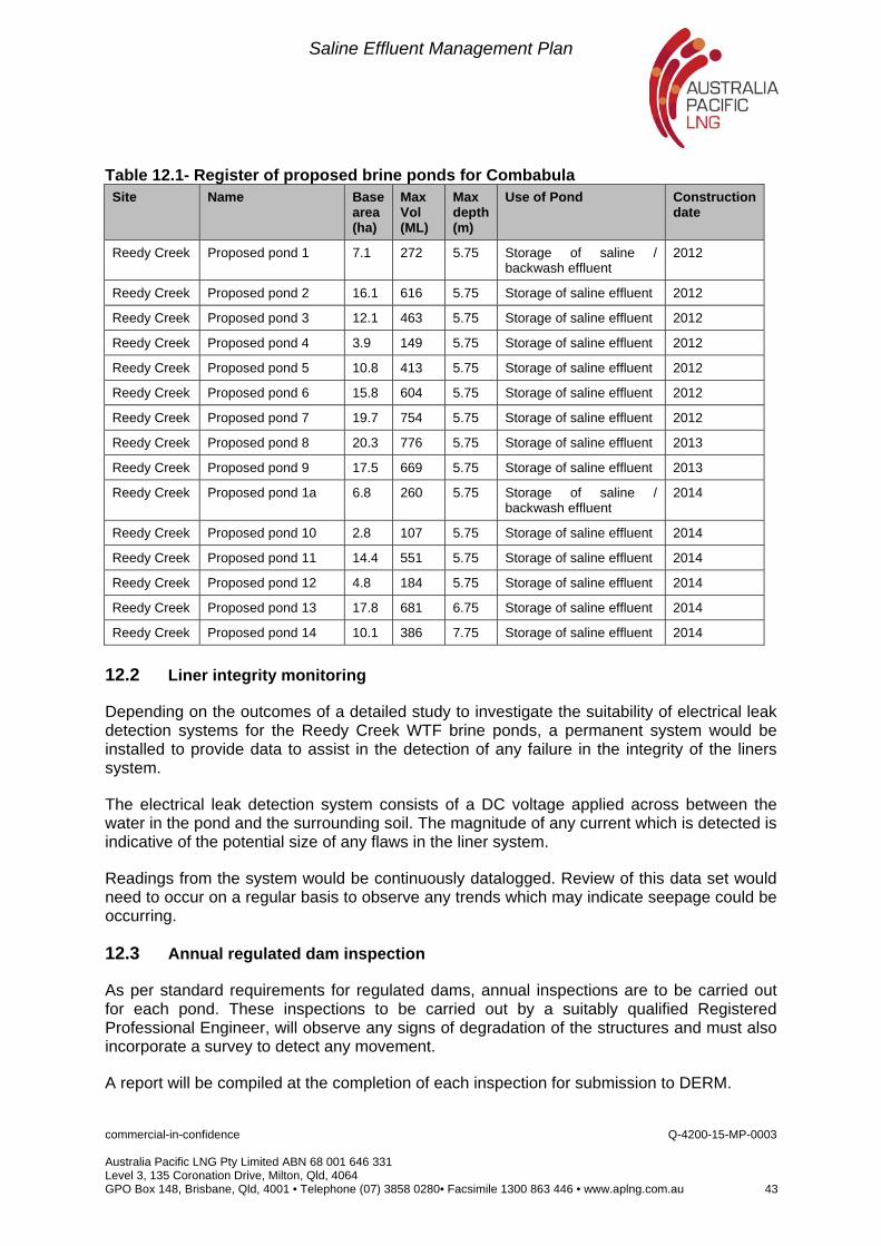
Saline Effluent Management Plan
commercial-in-confidence Q-4200-15-MP-0003 Australia Pacific LNG Pty Limited ABN 68 001 646 331 Level 3, 135 Coronation Drive, Milton, Qld, 4064 GPO Box 148, Brisbane, Qld, 4001 • Telephone (07) 3858 0280• Facsimile 1300 863 446 • www.aplng.com.au 43
Table 12.1- Register of proposed brine ponds for Combabula Site Name Base
area (ha)
Max Vol (ML)
Max depth (m)
Use of Pond Construction date
Reedy Creek Proposed pond 1 7.1 272 5.75 Storage of saline / backwash effluent
2012
Reedy Creek Proposed pond 2 16.1 616 5.75 Storage of saline effluent 2012
Reedy Creek Proposed pond 3 12.1 463 5.75 Storage of saline effluent 2012
Reedy Creek Proposed pond 4 3.9 149 5.75 Storage of saline effluent 2012
Reedy Creek Proposed pond 5 10.8 413 5.75 Storage of saline effluent 2012
Reedy Creek Proposed pond 6 15.8 604 5.75 Storage of saline effluent 2012
Reedy Creek Proposed pond 7 19.7 754 5.75 Storage of saline effluent 2012
Reedy Creek Proposed pond 8 20.3 776 5.75 Storage of saline effluent 2013
Reedy Creek Proposed pond 9 17.5 669 5.75 Storage of saline effluent 2013
Reedy Creek Proposed pond 1a 6.8 260 5.75 Storage of saline / backwash effluent
2014
Reedy Creek Proposed pond 10 2.8 107 5.75 Storage of saline effluent 2014
Reedy Creek Proposed pond 11 14.4 551 5.75 Storage of saline effluent 2014
Reedy Creek Proposed pond 12 4.8 184 5.75 Storage of saline effluent 2014
Reedy Creek Proposed pond 13 17.8 681 6.75 Storage of saline effluent 2014
Reedy Creek Proposed pond 14 10.1 386 7.75 Storage of saline effluent 2014
12.2 Liner integrity monitoring
Depending on the outcomes of a detailed study to investigate the suitability of electrical leak detection systems for the Reedy Creek WTF brine ponds, a permanent system would be installed to provide data to assist in the detection of any failure in the integrity of the liners system.
The electrical leak detection system consists of a DC voltage applied across between the water in the pond and the surrounding soil. The magnitude of any current which is detected is indicative of the potential size of any flaws in the liner system.
Readings from the system would be continuously datalogged. Review of this data set would need to occur on a regular basis to observe any trends which may indicate seepage could be occurring.
12.3 Annual regulated dam inspection
As per standard requirements for regulated dams, annual inspections are to be carried out for each pond. These inspections to be carried out by a suitably qualified Registered Professional Engineer, will observe any signs of degradation of the structures and must also incorporate a survey to detect any movement.
A report will be compiled at the completion of each inspection for submission to DERM.
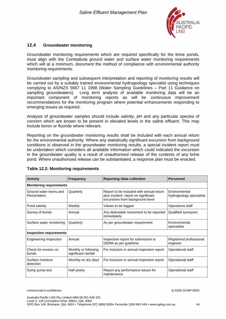
Saline Effluent Management Plan
commercial-in-confidence Q-4200-15-MP-0003 Australia Pacific LNG Pty Limited ABN 68 001 646 331 Level 3, 135 Coronation Drive, Milton, Qld, 4064 GPO Box 148, Brisbane, Qld, 4001 • Telephone (07) 3858 0280• Facsimile 1300 863 446 • www.aplng.com.au 44
12.4 Groundwater monitoring
Groundwater monitoring requirements which are required specifically for the brine ponds, must align with the Combabula ground water and surface water monitoring requirements which will at a minimum, document the method of compliance with environmental authority monitoring requirements.
Groundwater sampling and subsequent interpretation and reporting of monitoring results will be carried out by a suitably trained environmental hydrogeology specialist using techniques complying to AS/NZS 5667 11 1998 (Water Sampling Guidelines – Part 11 Guidance on sampling groundwaters). Long term analysis of available monitoring data will be an important component of monitoring reports as will be continuous improvement recommendations for the monitoring program where potential enhancements responding to emerging issues as required.
Analysis of groundwater samples should include salinity, pH and any particular species of concern which are known to be present in elevated levels in the saline effluent. This may include boron or fluoride where relevant.
Reporting on the groundwater monitoring results shall be included with each annual return for the environmental authority. Where any statistically significant excursion from background conditions is observed in the groundwater monitoring results, a special incident report must be undertaken which considers all available information which could indicated the excursion in the groundwater quality is a result of unauthorised release of the contents of any brine pond. Where unauthorised release can be substantiated, a response plan must be enacted.
Table 12.2: Monitoring requirements
Activity Frequency Reporting /data collection Personnel
Monitoring requirements
Ground water bores and Piezometers
Quarterly Report to be included with annual return plus incident report on significant excursions from background level
Environmental hydrogeology specialists
Pond salinity Weekly Values to be logged Operations staff
Survey of bunds Annual Any detectable movement to be reported immediately
Qualified surveyors
Surface water monitoring Quarterly As per groundwater requirement Environmental specialists
Inspection requirements
Engineering Inspection Annual Inspection report for submission to DERM as per guideline
Registered professional engineer
Check for erosion on bunds
Monthly or following significant rainfall
For inclusion in annual inspection report Operational staff
Surface moisture detection
Monthly on dry days For inclusion in annual inspection report Operational staff
Sump pump test Half yearly Report any performance issues for maintenance
Operational staff
Saline Effluent Management Plan
commercial-in-confidence Q-4200-15-MP-0003 Australia Pacific LNG Pty Limited ABN 68 001 646 331 Level 3, 135 Coronation Drive, Milton, Qld, 4064 GPO Box 148, Brisbane, Qld, 4001 • Telephone (07) 3858 0280• Facsimile 1300 863 446 • www.aplng.com.au 45
12.5 Water balance review
In order to verify and calibrate the water balance used for the sizing and planning of brine pond requirements, data will be collected to feed in to the model. The key data sets used for the water balance will be:
Daily pond level
Site weather station data – rainfall, temperature and evaporation
Weekly pond salinity
Daily meter readings of effluent discharge to ponds
12.6 Maintenance requirements
In response to findings from the regular inspection items detailed above and as regular maintenance activities a series of regular routines will be required of operational staff to ensure safe and efficient long term operation of the brine ponds and associated infrastructure. These requirements are detailed in the Operations and Maintenance Manual and include such procedures as:
Slashing of grass on bund
Flushing the drainage network
Inlet works maintenance
Cleaning and testing of instrumentation
12.7 Operations and monitoring manual
A manual designed to assist staff by providing continuous guidance throughout the operation of the brine ponds at Reedy Creek would be compiled. It would document all monitoring and inspection requirements for the ponds including the frequency, equipment and personnel, reporting and administrative requirements for all monitoring and inspection activities. The manual will also be the go-to location which list up to date confirmation of critical design data such as the mandatory reporting level and top operating water level of each dam. Maintenance requirements such as the requirements to control vegetation growth on bundwalls will be detailed in the manual.
With the manual a response plan is included for a range of incident scenarios including:
Pond seepage detected
Structural degradation of bund observed
Water level reaches Mandatory Reporting Level
Overtopping of spillway is imminent
Under all the above scenarios, a special report will be issued to DERM within a practical timeframe subsequent to the event.
A review of the Operations and Monitoring Manual will be carried out annually or at the commissioning of a new pond at the site or a significant change in the monitoring program.
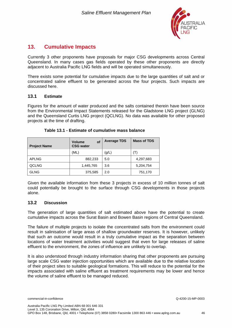
Saline Effluent Management Plan
commercial-in-confidence Q-4200-15-MP-0003 Australia Pacific LNG Pty Limited ABN 68 001 646 331 Level 3, 135 Coronation Drive, Milton, Qld, 4064 GPO Box 148, Brisbane, Qld, 4001 • Telephone (07) 3858 0280• Facsimile 1300 863 446 • www.aplng.com.au 46
13. Cumulative Impacts
Currently 3 other proponents have proposals for major CSG developments across Central Queensland. In many cases gas fields operated by these other proponents are directly adjacent to Australia Pacific LNG fields and will be operated simultaneously.
There exists some potential for cumulative impacts due to the large quantities of salt and or concentrated saline effluent to be generated across the four projects. Such impacts are discussed here.
13.1 Estimate
Figures for the amount of water produced and the salts contained therein have been source from the Environmental Impact Statements released for the Gladstone LNG project (GLNG) and the Queensland Curtis LNG project (QCLNG). No data was available for other proposed projects at the time of drafting.
Table 13.1 - Estimate of cumulative mass balance
Project Name Volume of CSG water
Average TDS
Mass of TDS
(ML) (g/L) (T)
APLNG 882,233 5.0 4,297,683
QCLNG 1,445,765 3.6 5,204,754
GLNG 375,585 2.0 751,170
Given the available information from these 3 projects in excess of 10 million tonnes of salt could potentially be brought to the surface through CSG developments in those projects alone.
13.2 Discussion
The generation of large quantities of salt estimated above have the potential to create cumulative impacts across the Surat Basin and Bowen Basin regions of Central Queensland.
The failure of multiple projects to isolate the concentrated salts from the environment could result in salinisation of large areas of shallow groundwater reserves. It is however, unlikely that such an outcome would result in a truly cumulative impact as the separation between locations of water treatment activities would suggest that even for large releases of saline effluent to the environment, the zones of influence are unlikely to overlap.
It is also understood through industry information sharing that other proponents are pursuing large scale CSG water injection opportunities which are available due to the relative location of their project sites to suitable geological formations. This will reduce to the potential for the impacts associated with saline effluent as treatment requirements may be lower and hence the volume of saline effluent to be managed reduced.
Saline Effluent Management Plan
commercial-in-confidence Q-4200-15-MP-0003 Australia Pacific LNG Pty Limited ABN 68 001 646 331 Level 3, 135 Coronation Drive, Milton, Qld, 4064 GPO Box 148, Brisbane, Qld, 4001 • Telephone (07) 3858 0280• Facsimile 1300 863 446 • www.aplng.com.au 47
A cumulative impact could result should a number of projects offer a similar range of salt products on the market. This will be an economic impact on the viability for any other market participants and may affect the viability of these reuse options by flooding the market and resulting in inability to move product.
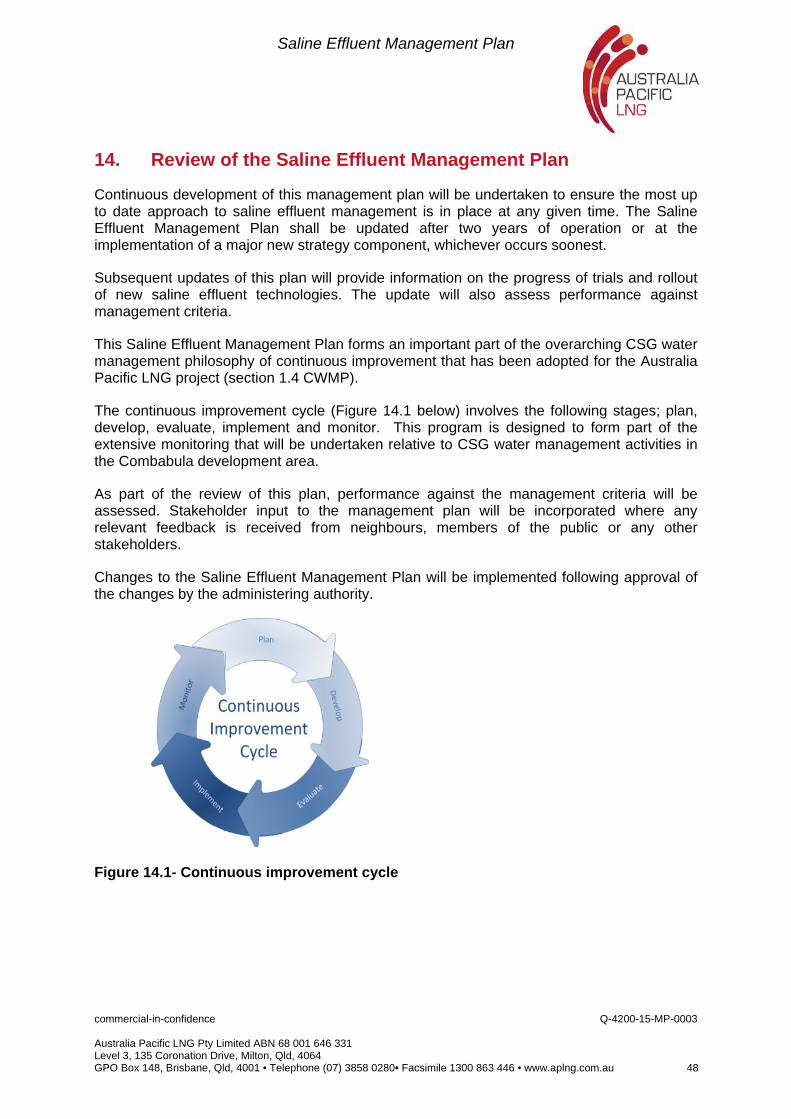
Saline Effluent Management Plan
commercial-in-confidence Q-4200-15-MP-0003 Australia Pacific LNG Pty Limited ABN 68 001 646 331 Level 3, 135 Coronation Drive, Milton, Qld, 4064 GPO Box 148, Brisbane, Qld, 4001 • Telephone (07) 3858 0280• Facsimile 1300 863 446 • www.aplng.com.au 48
14. Review of the Saline Effluent Management Plan
Continuous development of this management plan will be undertaken to ensure the most up to date approach to saline effluent management is in place at any given time. The Saline Effluent Management Plan shall be updated after two years of operation or at the implementation of a major new strategy component, whichever occurs soonest.
Subsequent updates of this plan will provide information on the progress of trials and rollout of new saline effluent technologies. The update will also assess performance against management criteria.
This Saline Effluent Management Plan forms an important part of the overarching CSG water management philosophy of continuous improvement that has been adopted for the Australia Pacific LNG project (section 1.4 CWMP).
The continuous improvement cycle (Figure 14.1 below) involves the following stages; plan, develop, evaluate, implement and monitor. This program is designed to form part of the extensive monitoring that will be undertaken relative to CSG water management activities in the Combabula development area.
As part of the review of this plan, performance against the management criteria will be assessed. Stakeholder input to the management plan will be incorporated where any relevant feedback is received from neighbours, members of the public or any other stakeholders.
Changes to the Saline Effluent Management Plan will be implemented following approval of the changes by the administering authority.
Figure 14.1- Continuous improvement cycle
Saline Effluent Management Plan
commercial-in-confidence Q-4200-15-MP-0003 Australia Pacific LNG Pty Limited ABN 68 001 646 331 Level 3, 135 Coronation Drive, Milton, Qld, 4064 GPO Box 148, Brisbane, Qld, 4001 • Telephone (07) 3858 0280• Facsimile 1300 863 446 • www.aplng.com.au 49
15. References
Origin Energy, Associated Water and Brine Pond, Front-end Engineering Design Basis, June 2010.
Department of Environment and Resource Management, Coal Seam Gas Water Management Policy, June 2010a
Department of Environment and Resource Management, draft Manual for Assessing Hazard Categories and Hydraulic Performance of Dams, August 2010b
Department of Environment and Resource Management, Guideline - Regulated dams in environmentally relevant activities, June 2010c
Worley Parsons, Brine Project, Pre-FEED Study Report, August 2010a
Worley Parsons, Saline Water Management Study, June 2010b