Embed Size (px)
Citation preview

PIPE COUPLINGSPIPE COUPLINGS (PTY)LTD
(PTY)LTD
The of Pipe Couplings, Flange Adaptors, Stepped Couplings and Dismantling Joints in the
Still Coupling since 1962.
Largest Manufacturer Southern Hemisphere.
ISSUE: 1108
COUPLE WITH CONFIDENCE
9001
ISO
ARPAL
TECHNICAL MANUAL

KLAMFLEX couplings and flange adaptors can be manufactured to suit almost any pipe outside diameteror flange drilling.
Information given in our catalogue generally only r e f e r s t o c o u p l i n g s f o r s t a n d a r d s i z e p i p e. Couplings and flange adaptors are manufactured to suit all standard pipe sizes. Where couplings are required for pipes in non-standard sizes and material or where standard outside diameters are not exact, e.g. GRP and AC pipe, details of the actual pipe OD's and tolerance should be stated for consideration by KLAMFLEX Pipe Couplings.
Design consideration should be given to the surface finish of pipe materials. By its very nature the KLAMFLEX coupling system relies upon good surface contact of the sealing rings, and considerationmust be given to pipe end preparation on pipes with naturally rough or uneven surface finish. Where surface dressing is required to remove weld beading, care must be taken not to overdress the pipe end causing pitting or flat spots. In general the recommen-dations of SABS 719-1971 and BS 534-1990 section 15 ensures a satisfactory surface finish.
Ovali ty, especial ly in larger diameter pipes, canfrequently be rectified either by jacking out, if the ovality is severe, or by rounding out by selective bolt tightening to give a uniform annular gap. Care must be taken when jacking so that internal finish is in no way damaged. N.B. Pipes which have local stiffening near the ends are sometimes impossible to correct for ovality.
Most rigid and semi-rigid pipe materials can be joinedwith KLAMFLEX couplings, e.g. steel, grey and ductile iron, asbestos cement, uPVC, GRP, concrete, etc. Some materials such as GRP need special consid-eration due to the structural strength of the material.
If in doubt of the suitability of KLAMFLEX cou-plings for use on your pipe, contact Pipe Couplings.
KLAMFLEX couplings can be used on both above and below-ground pipes but different design criteria apply. The following sections give some guidance on how to get the best use from Klamflex couplings.
INDEXTOPICPAGE
1
2
3
4
5
6
7
8
9
10
11
12
13
WORKING PRESSURE
EXPANSION & CONTRACTION
TEMPERATURE
SHEAR STRENGTH
BOLT TORQUE
PIPE END PREPARATION
ANGULAR DEFLECTION
FITTING RANGER PRODUCTS
MATERIAL SPECIFICATIONS
OD CHART
NOTES
LATERAL DISPLACEMENTGROUND SETTLEMENT
SETTING GAPSPRODUCT STORAGECATHODIC PROTECTION
FITTING INSTRUCTIONS(products up to 300mm NB)
FITTING INSTRUCTIONS(products above 300mm NB)
METHODS OF ANCHORING/SUPPORTING PIPES
TECHNICAL DATA

Working Pressure: This varies with coupling size and material used. Generally working pressure is up to 2/3rds of the maximum test pressure shown in the schedules of dimensions in our catalogue. Couplings are pressure rated to appropriate pipe standards in common use. For higher pressures, special couplings can be supplied.
KLAMFLEX couplings and flange adaptors for cast iron mains, carrying water, sewage or gas are suitable for the pressures for which the pipes are normally supplied. Generally flange adaptors are suitable for the pressure ratings of the flange to which they are connected. The pressure ratings stated in this catalogue are hydrostatic test pressures.
Each KLAMFLEX coupling will accommodate maximum pipe movement of 10mm and each flange adaptor 5mm. This is achieved by deformation of the sealing ring, not by a sliding action of the ring on the pipe and will cater for expansion and contraction resulting from temperature variations experienced under normal atmospheric conditions.
The resistance to pipe end sepeartion offered by couplings is dependant upon the number of variable installation factors such as pipe surface, pipe toler-ance, coupling component tolerances, etc, and is thus different for every case.
For complete safety it is advisable to assume that the worst conditions prevail for each installation.
CARE MUST BE TAKEN TO MAINTAIN SETTING GAPS WITHIN THE LIMITS GIVEN ON PAGE 5
WORKING PRESSURE
EXPANSION AND CONTRACTION
Pipelines under pressure are subject to forces which tend to separate the component parts. Flexible pipelines, e.g. those jointed with KLAMFLEX couplings, are particularly subject to forces acting at bends, tees or blank ends. Buried pipelines can generally be restrained by means of anchor blocks at abrupt changes of direction, with the minor forces at each straight joint being restrained by soil friction. With above ground pipelines, it is necessary to take full account of the thrusts produced by internal pressure and where required to restrain them with thrust blocks, anchorage or tie bars.
In the simple case of pressure acting on a blank end, the force P necessary to prevent pipe separation is given by:
KLAMFLEX couplings are NOT DESIGNED TO RESIST END LOAD due to pressure forces and there-fore such forces must normally be resisted by other means. At very low pressures however, friction between coupling and pipe may be sufficient in certain cases.
At a bend there is a force F tending to pull the end out-wards. This can result in axial forces F acting to separate the bend from the straight pipe at each KLAMFLEX coupling:
There must be sufficient anchorage to resist either P or both forces F e.g. in a buried system a thrust block may resist F, and above ground, sets of tie rods at each coupling would resist F.
I T I S I M P O RTA N T TO A P P R E C I AT E T H E MAGNITUDE OF THE END THRUSTS WHICH CAN RESULT FROM INTERNAL PRESSURE IN A PIPELINE.
=
=
P =
P =
Where d = pipe ODp = internal pressure
d = pipe o.d. (Mm) p = internal pressure (N/mm²) is given by: -
d = 508mm ODp = 16 bar = 1.6 N/mm²Then P = 1.6 x p x 508²
324293 N = 324.3 kN33.07 tonnes
ppd²
p x pd² Newtons
4
4
4
Example:
1

The recommended maximum operating temperature for Klamflex products is 90ºC when standard EPDM gaskets are used. Please contact Klamflex Pipe Couplings for higher operating temperatures. If temperature fluctuations occur further re-tightening of the bolts may be required.
For this reason where maintenance free operation is required, Klamflex couplings are not recommended for central heating systems, which do not operate at constant temperatures.
TEMPERATURE
Couplings up to DN 1500mm are normally capable of withstanding a shear force corresponding to the weight applied by a 10m length of coupled pipe that is full of water, i.e. a length of pipe suspended between two couplings. Rangers are not suitable for this duty and the pipe should be supported to prevent sagging.
Couplings up to 324mm OD M12 bolts - 65-80NmCouplings over 324mm OD M16 bolts - 80-120Nm
These torque figures relate to 16 bar working pressure.
SHEAR STRENGTH
RECOMMENDED BOLT TORQUE
Dimension 'L' is the length from the ends of the pipes which must be rounded where necessary to meet the tolerance required. It is also the amount of "Clearance" to permit coupling assembly, and applies equally for coupling sleeves with centre register, without centre register or with locating plug.
For distance 'L' the pipe must be free from any peaks, flats, depressions, roll marks, weld beads or any other such defects likely to affect the seal. See fig.1 Where it is necessary to slide the coupling completely onto one pipe end, the wrapping must be cut back on site for minimum distance "M". For closing connections, only coupling sleeves without register or with locating plugs may be used. See fig.2
PIPE END PREPARATION
2
Coupling Dia.
326mm -
326mm -
326mm +
83mm
102mm
178mm
102mm
102mm
150mm
152mm
152mm
254mm
SleeveLength
Distance L for normal coupling
assembly
Distance M for closing
connections
FIG. 1
FIG. 2
2

Each coupling will allow for a setting angularity as follows:
a
Flange adaptors will allow for a setting angularity of half the above figures.
The above schedules should only be used when the pipes will not move in service. For other conditions we recom-mend working to half these figures to allow for in-service flexibility.
The ability of a coupling to accommodate angular deflec-tion on installation and in service enables it to be used in the following valuable ways:
Take up minor misalignment in straight pipes e.g. at closing lengths.
Lay pipes to long radius curves without special bends.
Absorb large amounts of expansion movement at right angles to the pipelines.
Accommodate ground settlement.
ANGULAR DEFLECTION
Coupling Size Angle Inclination
Up to 457mm OD
Over 457mm to 610mm OD
Over 610mm to 762mm OD
Over 762mm to 1219mm OD
Over 1219mm to 1829mm OD
Over 1829mm OD
±6º
±5º
±4º
±3º
±2º
±1º
1 in 10
1 in 12
1 in 15
1 in 20
1 in 30
1 in 60
1.
2.
3.
4.
3

4
Lateral displacement between two pipes to be joined cannot be accommodated by a single coupling. Two couplings must be used and a small centre piece of pipe may be allowed to articulate the take up displacement.
Method of calculating length of the centre pipe.
EXAMPLEPipe OD=762mmLateral displacement to be accommodated = 180mmMinimum closing length = 180 x 15 = 2700mm
N.B. For KLAMFLEX flange adaptors these lengths must be doubled.
Ground settlement e.g. where a pipe leaves an underground structure, can be accommodated by a pair of KLAMFLEX couplings.All pipe trenches are of necessity excavating below the invert to allow for pipe bedding. Where this bedding is to be flexible, e.g. granular fill, some settlement of the pipe will inevitably occur when it is backfilled. To relieve pipe
LATERAL DISPLACEMENT
GROUND SETTLEMENT
Pipe nominal diameter (mm) Minimum Length (mm)
Up to 457mm OD
Over 457mm to 610mm OD
Over 610mm to 762mm OD
Over 762mm to 1219mm OD
Over 1219mm to 1829mm OD
Over 1829mm OD
Displacement Y x 10
Displacement Y x 12
Displacement Y x 15
Displacement Y x 20
Displacement Y x 30
Displacement Y x 60
stresses, coupling A should be installed as close to the structure as possible. Coupling B permits pipe C to angulate, taking up settlement Y. The length of pipe C is determined as in above diagram, though its structural strength in bending must be considered.
5
It is generally desirable that adjacent pipe ends do not make contact with each other in service. If there is insufficient gap, particularly on above ground pipes, the pipeline will tend to buckle as temperatures increase. We recommend maximum safe accumulated gaps which should not be exceeded in service. Also given are recommended setting gaps which allow for expansion and contraction or angu-larity in service.Consideration of actual temperature movement or deflec-tion conditions may lead to different initial setting gaps.
Where locating plugs are used, the setting gap should be increased by 9,5mm for sizes up to 324mm OD and 12,5mm for sizes above 324mm OD to avoid contact with the plugs.
Products must be stored in a cool dark place below 20 degrees centigrade, store away from direct sunlight, electrical discharges and sparking electric motors. Always store sealing rings in an unstressed condition, never hang even for a short time.
THE MAXIMUM DIMENSIONS ABOVE MUST NOT BE EXCEEDED UNDER ANY CIRCUMSTANCES
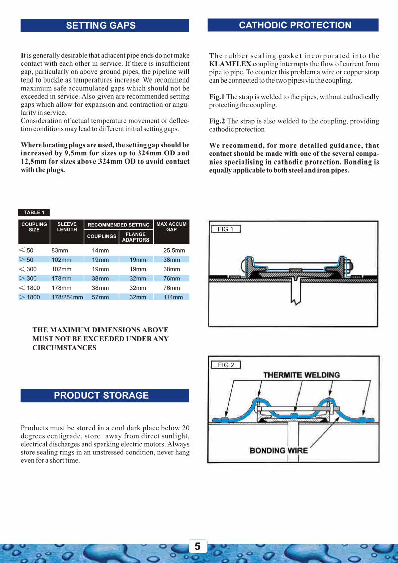
The rubber sea l ing gasket incorpora ted in to the KLAMFLEX coupling interrupts the flow of current from pipe to pipe. To counter this problem a wire or copper strap can be connected to the two pipes via the coupling.
Fig.1 The strap is welded to the pipes, without cathodically protecting the coupling.
Fig.2 The strap is also welded to the coupling, providing cathodic protection
We recommend, for more detailed guidance, that contact should be made with one of the several compa-nies specialising in cathodic protection. Bonding is equally applicable to both steel and iron pipes.
SETTING GAPS
PRODUCT STORAGE
TABLE 1
CATHODIC PROTECTION
SLEEVE LENGTH
COUPLING SIZE
RECOMMENDED SETTING
COUPLINGS FLANGEADAPTORS
MAX ACCUMGAP
83mm
102mm
102mm
178mm
178mm
178/254mm
50
50
300
300
1800
1800
<_
<_
<_
14mm
19mm
19mm
38mm
38mm
57mm
19mm
19mm
32mm
32mm
32mm
25,5mm
38mm
38mm
76mm
76mm
114mm
>
>
>
FIG 2FIG 1
FIG 2FIG 1

METHODS OF ANCHORING / SUPPORTING PIPES
Fig. 1
Fig. 2
For anchoring and supporting pipes this method allows freedom of movement within the capabilities of the KLAMFLEX system, and controls the axial movement over a maximum of two couplings. If the free pipe moves to the full extent in one direction, the accumulated gap should be within the limits of one coupling. Clear pipe span not to exceed 10 metres
Pipeline incorporating KLAMFLEX anchored couplings.
A.
B.
C.
Anchored to withstand resolved thrust at the ends of all straight runs.
Intermediate anchor points strong enough to prevent creeping of the pipes.
Guide supports with loose strap over the pipe otherwise cradles will be suitable, e.g. if the line is not straight, then all anchors and guides, A, B and C must be designed to withstand the resolved thrust but still allow longitudinal expansion of the pipes through the guide supports. Pipe should not be laid to the maximum deflection.
D. KLAMFLEX anchored coupling.
6

7
KLAMFLEX Quickfit Couplings range in size from 60mm pipe OD to 326mm pipe OD and are supplied completely assembled and need only be placed on the correctly aligned pipes and fitted according to KLAMFLEX installation instructions. The unit should not be dismantled, fitting of KLAMFLEX Quickfit Flange Adaptors shall be conducted to the same proce-dure:
1. Ensure the pipe ends are correctly prepared. All surfaces with which gaskets come into contact are to be thoroughly cleaned immediately before coupling installation, thus allowing the gaskets to seal effectively. A distance of one centre sleeve length plus 50mm on each pipe end should be prepared to remove all loose rust, dirt and foreign matter. It is important that the pipe ends be smooth, concentric and within specified tolerances (SABS 719-1971 section 4, BS 534-1990 section 14).
2. Reference marks should be placed on the pipes to facilitate in centering the Quickfit Coupling over the gap between the pipes in accordance to KLAMFLEX setting gaps for each specific coupling.
3. A suitable gasket lubricant (such as soapy water) must be applied to the pipe ends and the accessible faces of the sealing rings, care must be taken to ensure the gaskets are clean. The KLAMFLEX Quickfit Couplings is pushed as a complete unit onto the pipe already in position.
4. The pipe ends shall be aligned leaving the appropriate gap. Adjustment of the trench bed may be necessary. The setting gap or distance between the pipe ends after coupling has been installed, (Pg: 5). These distances for straight couplings are tabulated in table 1 (Pg: 5). Where locating plugs are used the gap should be increased by 9.5mm for sizes up to 326mm OD and 12.5mm for sizes above 326mm OD to avoid contact with plugs.
5. The centre sleeve shall then be moved into position, centred over the gap with reference to the marks made on the pipe ensuring the coupling is central over the gap.
6. As the bolts are already installed, the bolts need only be tightened to the KLAMFLEX recommended torque. To ensure correct end-ring seating and gasket compression, the bolts must be tightened in pairs at diametrically opposite positions in a circular sequence. Bolt up evenly giving nuts one or two turns at a time to the prescribed torque rating of 65 - 80Nm. The tightening sequence assures that the end-rings are pulled evenly to compress the gaskets uniformly and to maintain appropriate gap. The tightening of the bolts shall be repeated as many times as necessary to bring all fasteners to the required torque rating, so as to provide a
FITTING INSTRUCTIONS
PRODUCTS UP TO 300mm N/B
leakproof installation at the specified test pressure. If an effective sealing is not attained at the recommended torque, the coupling shall be loosened, realigned and the bolts re-torqued.
Torque ratings for GRP pipes are to be decided on after consultation with the specific GRP pipe supplier, as each supplier develops pipe with its own specific glass filament configuration.
Note: These specifications relate to product operating at 16 bar working pressure. Contact Klamflex for torque specifications at different working pressures.

8
KLAMFLEX Unassembled Couplings are supplied for sizes above 326mm pipe OD. As the name suggests the couplings are supplied with sleeves, flanges, sealing rings and bolts unassembled. Fitting of KLAMFLEX Unfitted shall be conducted according to the following procedure. 1. Ensure the pipe ends are correctly prepared. All with which the gaskets come into contact are to be thoroughly cleaned immediately before coupling installation, thus allowing the gaskets to seal effectively. A distance of one centre sleeve length plus 50mm on each pipe end should be prepared to remove all loose rust, dirt and foreign matter. It is important that the pipe ends be smooth, concentric and within specified tolerances (SABS 719-1971 section 5, BS 534-1990 section 14). It is important that weld beads are ground flush maintaining correct surface profile.
2. Reference marks should be placed on the pipes to facilitate in centering the coupling sleeve over the gap between the pipes in accordance to KLAMFLEX setting gaps for each specific coupling (refer to table 1. Pg 5).
3. Larger-diameter pipe and couplings may become out of round in transportation and handling. Therefore it is normal to expect to use jacks, wedges, shims or other means to facilitate assembly of the coupling on the pipe ends.
4. The end rings shall be placed on the pipes.
5. A suitable gasket lubricant (such as soapy water) must be applied to the pipe ends and the sealing rings, care must be taken to ensure the gaskets are clean. The gaskets shall then be placed on the pipe ends with bevelled faces toward the centre sleeve.
6. The centre sleeve shall be placed on one pipe end.
7. The pipe ends shall be aligned leaving the appropriate gap (refer to table 1. Pg 5). Adjustment of the trench bed may be necessary. Where locating plugs are used, the setting gap should be increased by 9.5mm for sizes up to 326mm OD and 12.5mm for sizes above 326mm OD to avoid contact with the plugs.
8. The centre sleeve shall then be moved into position, centred over the gap with reference to the marks made on the pipe ensuring the coupling is central over the gap.
9. When the centre sleeve is properly placed, with the gap between the OD of the pipe and the ID of the centre sleeve distributed evenly the gaskets shall be moved into position with bevelled faces of the gaskets against the centre sleeve end. End-rings shall be moved into place behind the gaskets.
10. Bolts shall be installed in the end-rings holes and tightened to the KLAMFLEX recommended torque.To assure correct end-ring seating and gasket compression, the bolts must be tightened in pairs at diametrically
FITTING INSTRUCTIONS
PRODUCTS ABOVE 300mm N/B
opposite positions in a circular sequence. Bolt up evenly giving nuts one or two turns at a time to the prescribed torque rating of 80 - 120Nm (M16 bolt).
The tightening sequence assures that the end-rings are pulled evenly to compress the gaskets uniformly and to maintain appropriate gap. The tightening of the bolts shall be repeated as many times as necessary to bring all fasten-ers to the required torque rating, so as to provide a leakproof installation at the specified test pressure. If an effective sealing is not attained at the recommended torque, the coupling shall be loosened, realigned and the bolts re-torqued.Torque ratings for GRP pipes are to be decided on after consultation with the specific GRP pipe supplier, as each supplier develops pipe with its own specific glass filament configuration.
Note: These specifications relate to product operating at 16 bar working pressure. Contact Klamflex for torque specifications at different working pressures.

Dissasemble the coupling and check all parts.
Measure the length of the coupling and subtract setting gap
Divide the result of the above measurement by two and mark both pipes.
Complete the assembly to finger tight and position coupling on mark.
Tighten bolts - as per Klamflex manual - to recommended torque.
INSTALLING RANGER PRODUCTS
The coupling is supplied completly assembled.
22
Insert the second pipe to the mark and start tightening.
3 8
4 9
5 10
Start assembling the coupling on one of the pipes to be joined.
Apply a non-toxic soapy lubricant to the gasket area as shown. Check gaskets on completed assembly for proper contact and deformations.
6
7
1
9

10
SABS 936:1969 Grade SG42BS EN 1563:1997SANS 1431:1987 Grade 300 WABS EN 10025:2004 Grade S275
SANS 1431:1987 Grade 300 WABS EN 10025:2004 Grade S275
SABS 936:1969 Grade SG42BS EN 1563:1997
SABS 936:1969 Grade SG42BS EN 1563:1997
SANS 1431:1987 Grade 300 WABS EN 10025:2004 Grade S275
SABS 936:1969 Grade SG42BS EN 1563:1997
SABS 936:1969 Grade SG42BS EN 1563:1997
SANS 1431:1987 Grade 300 WABS EN 10025:2004 Grade S275
SABS 936:1969 Grade SG42BS EN 1563:1997SANS 1431:1987 Grade 300 WABS EN 10025:2004 Grade S275
SABS 936:1969 Grade Sg42BS EN 1563:1997SANS 1431:1987 Grade 300 WABS EN 10025:2004 Grade S275
BS EN 10025:2004 Grade FE430ABS EN 10025:2004
SANS 1431:1987 Grade 300 WABS EN 10025:2004 Grade S275
Ductile Iron
Rolled Steel
Rolled Steel
Ductile Iron
Ductile Iron
Rolled Steel
Ductile Iron
Ductile Iron
Rolled Steel
Ductile Iron
Rolled Steel
Ductile Iron
Rolled Steel
Ductile Iron
Steel Plate
Centre Sleeve
End Ring
DedicatedUp to 140mm OD
Over 140mm OD
Ranger Up to 300mm OD (315 -322)
Over 300mm OD (incl. 322-340)
DedicatedUp to 328mm OD
Over 328mm OD
RangerUp to 600mm OD
Flange Adaptor Body
End Ring
Table Flange
DedicatedUp to 140mm OD
Over 140mm OD
Ranger Up to 600mm
(315-322mm)
DedicatedUp to 328mm OD
Over 328mm OD
Ranger Up to 600mm OD
MATERIAL SPECIFICATIONS
COUPLINGS
FLANGE ADAPTORS

11
LOW Carbon Unalloyed Steel
Hot Dipped Galvanised
Electro Galvanised
Stainless Steel
SABS 1143:1977 Grade 4.8 (8.8 for higher pressure)BS 970-1:1996SABS 763:1988BS EN ISO 1461:1999
BS EN 12329:2000/ BS EN 12330:2000
Available on request
BOLTS: MATERIAL
LOW Carbon Unalloyed Steel
Electro Galvanised
Hot Dipped Galvanised
SABS 135:1991BS 970-1:1996
BS EN 12329:2000/ BS EN 12330:2000
BS 729:1986
NUTS: MATERIAL
Carbon SteelStainless Steel
BS 970-1:1996Available on request
STUDS: MATERIAL
LOCATING CENTER REGISTER
Removable Centre RegisterFixed Centre Register
Mild Steel Cadmium Plated
Mild Steel
HARNESS LUGS
Steel Plate SANS 1431:1987 Grade 300 WABS EN 10025:2004 Grade S275
HARNESS / RESTRAINED FLANGE ADAPTOR TIE ROD BOLTS
SANS 1431:1987 Grade 300 WABS 970-1:1996Grades 4.8 or 8.8 Dependant on PressureUncoated or Electro-galvanised zinc to BSEN 12329:2000/ BSEN 12330:2000Available on request
Carbon Steel Bar
Coating
Stainless Steel
RUBBER COMPRESSION SEALING GASKET: MATERIAL
SPECIALISED COATINGS
Fusion Bonded Epoxy to SABS 1217:1984Certified Non Toxic for use on potable water distribution systems in accordance with BS 6920 (WRAS)
E.P.D.M
Certified Non Toxic for use on potable water distribution systems in accordance with BS 6920 (WRAS)
SABS 974:1986 related ISO 4633:1983BS EN 681-1:1996Nitrite sealing gaskets available on request.

ST
EE
L B
S 1
387
ST
EE
L S
AB
S 6
2 M
ED
IUM
ST
EE
L S
AB
S 7
19
ST
EE
L IS
O 4
200
SE
R 1
ST
EE
L A
PI 5
L
ST
EE
L B
S 3
600/
3601
DU
CT
ILE
IRO
N IS
O 2
531
: B
S 4
772
GR
P (
O.D
. Can
Var
y b
y M
anu
fact
ure
r)
AS
BE
STO
S C
EM
EN
T C
.O.D
. (S
ou
th A
fric
a)
AS
BE
STO
S C
EM
EN
T C
.I.D
. (S
ou
th A
fric
a)
AS
BE
STO
S C
EM
EN
T C
.I.D
. (S
ou
th A
fric
a)
AS
BE
STO
S C
EM
EN
T C
.I.D
. (S
ou
th A
fric
a)
AS
BE
STO
S C
EM
EN
T C
.I.D
. (S
ou
th A
fric
a)
AS
BE
STO
S C
EM
EN
T C
.I.D
. (S
ou
th A
fric
a)
AS
BE
STO
S C
EM
EN
T C
.I.D
. (S
ou
th A
fric
a)
AS
BE
STO
S C
EM
EN
T M
ET
RIC
BS
486
AS
BE
STO
S C
EM
EN
T M
ET
RIC
BS
486
AS
BE
STO
S C
EM
EN
T M
ET
RIC
BS
486
IMP
CA
ST
IRO
N A
SB
ES
TOS
CE
ME
NT
IMP
CA
ST
IRO
N A
SB
ES
TOS
CE
ME
NT
mm
inch
es
max
max
CL
6
CL
12
CL
18
CL
24
CL
30
CL
36
CL
15
CL
20
CL
25
CL
AB
CL
CD
15 0.5
21.3
21.7
21.3
21.4
21.4
20 0.75
26.9
27.2
26.9
26.7
26.8
25 1
33.7
34.2
33.7
33.4
33.6
32 1.25
42.4
42.9
42.4
42.4
42.3
40 1.5
48.3
48.8
48.3
48.3
48.3
55.9
55.9
50 2
60.3
60.8
60.3
60.3
60.4
69 69 69.1
69.1
65 2.5
76.1
76.6
76.1
73.0
76.1
82.3
82.3
80 3
88.9
89.5
88.9
88.9
88.9
98.0
96 96 95.5
95.5
100 4
114.
3
114.
9
114.
3
114.
3
114.
3
118.
0
116
122
122
121.
9
121.
9
125 5
139.
7
140.
6
139.
7
141.
3
139.
7
144.
0
150
149.
9
149.
9
150 6
165.
1
166.
1
168.
3
168.
3
168.
3
170.
0
168
177
168
174
180
188
196
177
177
177.
3
177.
3
175 7
193.
7
204.
7
204.
7
200 8
219.
1
219.
1
219.
1
219.
1
222.
0
220.
5
232
222
229
239
250
262
232
232
240
232.
2
232.
2
225 9
244.
5
259
259
268
259.
1
259.
1
250
10
273.
1
273.
0
273.
1
273.
0
274.
0
272.
1
286
274
284
295
304
318
286
286
295
286
286
300
12
323.
9
323.
9
323.
9
323.
9
326.
0
327
345
328
340
353
365
378
334
345
356
333.
8
345.
4
350
14
355.
6
355.
6
355.
6
355.
6
378.
0
379
426
378
382
396
412
426
440
392
405
419
378
399.
3
400
16
406.
4
406.
4
406.
4
406.
4
429.
0
413
430
436
450
468
484
503
448
463
478
439
453.
1
450
18 457
457
457.
2
457.
0
480.
0
464
507
483
488
506
524
545
566
498
515
532
492
506.
9
500
20 508
508
508
508
532
515
587
535
543
560
583
606
629
568
586
605
545
560.
3
550
22 559
559
559
598
613.
7
600
24 610
610
609.
6
610
635
617
667
638
651
672
699
727
755
654
672
691
650
667
650
26 660
660.
4
660
703
720.
3
700
28 711
711
711.
2
711
738
719
744
760
784
816
761
780
801
755
773.
2
750
30 762
762
762
807
826
800
32 813
813
812.
8
813
842
821
850
868
896
932
808
830
852
860
879.
3
850
34 864
863.
6
864
912
900
36 914
914
914.
4
914
945
924
956+
976
1008
1048
927
952
977
964
984.
5
1000 40 1016
1016
1016
1016
1048
1025
1062
1084
1120
1165
970
996
1024
1068
1090
.2
1050 42 1067
1067
1066
.8
1121
1143
1100 44 1118
1118
1117
.6
1172
1200 48 1219
1219
1219
.2
1219
1255
1229
1277
1300
.5
1300 52 1321
1320
.8
1400 56 1422
1422
1422
.4
1422
1462
1433
1600 64 1626
1626
1625
.6
1626
1668
1637
1800 72 1829
1829
1828
.8
1829
1875
1841
2000 80 2032
2032
2032
2032
2080
2045
PIP
E N
OM
INA
L B
OR
EPIP
E O
UTS
IDE
DIA
MET
ERS
OF
CO
MM
ON
PIP
E M
ATER
IALS
AL
L D
IME
NS
ION
S A
RE
IN M
ILL
IME
TR
ES
(m
m)
TO A
SS
IST
US
IN M
AK
ING
TH
E C
OR
RE
CT
PR
OD
UC
T S
EL
EC
TIO
N F
OR
YO
U P
LE
AS
E P
RO
VID
E A
S M
UC
H O
F T
HE
FO
LL
OW
ING
INF
OR
MA
TIO
N A
S P
OS
SIB
LE
(I)
PIP
E O
UT
SID
E D
IAM
ET
ER
OR
PIP
E M
AT
ER
IAL
AN
D C
LA
SS
(II)
WO
RK
ING
PR
ES
SU
RE
(III)
MA
TC
HIN
G F
LA
NG
E D
RIL
LIN
G F
OR
FL
AN
GE
AD
AP
TOR
S A
ND
DIS
MA
NT
LIN
G J
OIN
TS
(IV
) P
RO
DU
CT
IN S
YS
TE
M (
WA
TE
R, S
EW
AG
E, C
HE
MIC
AL
S, G
AS
, AIR
, OIL
ET
C)
(V)
FL
UID
/ G
AS
TE
MP
ER
AT
UR
E IF
AVA
ILA
BL
E
UP
VC
, MP
VC
, PE
, HD
P
1620
2532
4050
6375
9011
012
514
016
018
020
022
525
0 3
1528
035
540
045
050
056
063
071
080
090
010
0012
0014
0016
0018
0020
00
TH
ES
E P
IPE
S A
RE
QU
OT
ED
US
ING
TH
E S
AM
E D
IME
NS
ION
FO
R N
OM
INA
L B
OR
E A
S P
IPE
OU
TS
IDE
DIA
ME
TE
R
12

NOTES:
13

STEPPED COUPLINGSSTEPPED COUPLINGS
RANGER COUPLINGSRANGER COUPLINGS
Where pipe ends of different outside diameters have to be connected, stepped couplings can be provided. The range is extensive and covers a vast array of pipe sizes and materials. The jointing of dissimilar materials, requiring different fastener torque values, is facilitated by the inclusion of a profile plate.
Ranger products, in the form of wide range couplings and flange adaptors, are designed to join various outside diame-ters with the same or different nominal bore.Because of the wide range tolerance on O.D. (Up to 23mm) a single RANGER coupling can connect steel, ductile iron, asbestos cement and other rigid pipe materials.The ability of Ranger couplings to join dissimilar pipe materials is a bonus feature in both repair or permanent situations.
DEDICATED COUPLINGSDEDICATED COUPLINGS
Klamflex straight couplings join pipes of the same outside diameter in the current production range from 50 - 3500mm.The couplings can be manu-factured to both imperial and metric dimensions in any size within the product range. Straight couplings are suit-able for virtually all rigid pipe materials.
JUNIOR COUPLINGSJUNIOR COUPLINGS
A small bore range of couplings and tees in sizes from 15-50mm, specifically designed for use on plain ended steel service lines. Featuring cast and steel construction, Junior products are galvanised for long term corros ion protect ion. An
extremely simple jointing method which eliminates the need for on site pipe threading.
FLANGE ADAPTORSFLANGE ADAPTORS
RANGER ADAPTORSRANGER ADAPTORS
Covering a similar range to the straight coupling, Klamflex Flange Adaptors are manufac-tured to join plain ended pipe to flanged valves, fittings, flow meters and pipes. Flange drillings are available to all international standards or to customer specifications.
RANGER Flange adaptors facilitate the connection of plain ended pipe to flanged ancilliary products, in the same range of outside diameters, and multi drilling f langes further s impl i fy installation.
DISMANTLING JOINTSDISMANTLING JOINTS
A double flanged composite fitting, featuring a telescopic action between a flanged spigot and a flange adaptor, specially designed to provide longitudinal adjustment in flanged pipe systems. Dismantling joints also provide a simple method for the installation and removal of flanged valves, pumps, flow
meters and flanged pipework. Tie rods are provided for final anchoring and location and also double as flange jointing bolts reducing the number of these required.
KLAMFLEX PIPE COUPLINGS (PTY) LTD. RESERVE THE RIGHT TO MODIFY THE SPECIFICATIONS AND INFORMATION CONTAINED WITH ONGOING PROGRAMMES OF PRODUCT RESEARCH, DEVELOPMENT AND IMPROVEMENT.
PRODUCTS AVAILABLE FROM KLAMFLEX
P.O. Box 4073Luipaardsvlei 1743South Africa
Tel: +27 11 762 5326Fax: +27 11 762 5674
52 Fransen StreetChamdorKrugersdorp 1740
E-mail: [email protected]: www.klamflex.com
PIPE COUPLINGSPIPE COUPLINGS (PTY)LTD
(PTY)LTD
KLAMFLEXKLAMFLEX
SolarAd - 9
482
9001
ISO
ARPAL