Embed Size (px)
Citation preview

1
AMERICAN NATIONAL STANDARD ANSI B7.1-2000
American National Standard
Safety Requirements forthe Use, Care and Protec-tion of Abrasive Wheels
1 Scope and definitions
1.1 Scope
This safety standard sets forth requirementsfor the safe use, care and protection of abra-sive wheels and the machines for which theyare designed. Included in this standard arethe requirements for safety guards, flanges,chucks and proper storage, handling andmounting techniques.
Exclusions from this standard are natural sand-stone, pulpstone and coated abrasive prod-ucts. This standard also does not apply tomachines using loose abrasives.
1.2 Definitions
1.2.1 abrasive wheel/grinding wheel:* Anabrasive wheel is a grinding tool consisting ofabrasive grains held together by organic orinorganic bonds. Diamond and reinforcedwheels are included under this definition.
1.2.2 actuating controls: Operator controlsused to initiate machine motion (see trip).
1.2.3 arbor: A shaft, mandrel, spindle or axle.
1.2.4 barrier: A physical boundary to a hazard.
1.2.5 base [frame] [head] [housing] [stand]:The basic and primary structure of the ma-chine.
1.2.6 blade tensioning: Steel centered su-per abrasive cut-off wheels are "tensioned"when manufactured to neutralize the residualstresses within the steel center so that thewheels will run true at the speed for whichthey are intended.
E 1.2.1 abrasive wheel/grinding wheel
Illustration 1 – Examples of the various typesof abrasive wheels included in this standard
E 1.2.6 blade tensioning
Various residual stresses are imparted to thewheel's steel center during manufacture ofsteel, during manufacture of the wheel centerand during manufacture of the wheel itself.These stresses tend not to be evenly distrib-uted throughout the core. Therefore, in opera-tion, the wheel tends to not run true, i.e. ittends to wobble or flutter.*Definition taken from ANSI B11.9.

2
ANSI B7.1-2000
1.2.7 blotters: Compressible discs or wash-ers usually of blotting paper stock, plastic,cardboard or gasket material, used betweenthe wheel and flanges when mounting. Seesection 5.6.
1.2.8 bushing, reducing: See reducing bush-ings.
1.2.9 center: A part that supports a workpieceon its axis of rotation.
1.2.10 chuck: A fixture designed to holdabrasive segments or certain types of abra-sive wheels and is mounted on a machinespindle or machine face plate.
1.2.11 coated abrasive tool:* A coated abra-sive tool consists of a layer of abrasive par-ticles firmly attached to a paper, cloth or fiberbacking, or other flexible bonding material bymeans of a bonding agent.
1.2.12 collet (collet chuck): A holder forgripping a workpiece or tool.
1.2.13 component: A constituent part.
1.2.14 configuration: A functional arrange-ment.
1.2.15 control, operator: An operator acti-vated push button, switch, lever, hand wheelor other device that initiates, cycles, controlsor stops motion of the machine.
1.2.16 control system: Sensors, manual in-put and mode selection elements, interlockingand decision-making circuitry and output ele-ments to the machine operating devices andmechanisms.
1.2.17 coolant: A fluid that is directed on thematerial or a workpiece and tool to dissipateheat and to provide lubrication for the cuttingprocess (machining process) (material removalprocess).
1.2.18 cover, movable: An attachment thatshields the opening of the work station, butcan be moved to provide access.
1.2.19 design: Develop and plan machineconstruction to meet the intended purposeand function.
*Definition taken from ANSI B11.9.

3
ANSI B7.1-2000
1.2.20 device: A piece of equipment or amechanism designed to serve a special pur-pose or perform a special function. (See de-vice, safety.)
1.2.21 device, auxiliary: A device that byitself does not safeguard hazards but is re-quired to ensure the proper operation of thesafeguarding (guards, safety devices or meth-ods).
1.2.22 device, safety: A means that detectsor prevents inadvertent access to a hazard(see safeguarding).
1.2.23 discrete parts or assemblies: Sepa-rate or distinct units or elements that areconsidered output or work in progress of anindustrial machine or manufacturing system.
1.2.24 dressing:* Dressing is the process ofremoving bond material from around the cut-ting grains or diamonds in order to exposenew, sharp cutting edges and to provide chipclearance for the material removal process.(See truing.)
1.2.25 enclosure, additional: Additional en-closure is protection which isolates the opera-tion from people in the surrounding area. (Seesplash shield.)
1.2.26 exhaust zone: The effective area ofthe ventilation system used for control of dustand fumes.
1.2.27 flanges: Flanges are collars, discs orplates between or against which wheels aremounted and are referred to as adaptor, sleeve,straight relieved or straight unrelieved types.
1.2.28 frame: See base.
1.2.29 grind cycle: The period of time, eithercontinuous or intermittent, during which thegrinding tool is engaged to remove materialfrom the workpiece.
1.2.30 grinding machine:* A grinding ma-chine, designed primarily for metal removal,presents a grinding tool against a workpiece,producing a change in shape, size, and sur-face finish. It may also be used for grindingmaterial other than metals such as glass, ce-ramics, plastics, and rubber.
*Definition taken from ANSI B11.9.

4
ANSI B7.1-2000
1.2.31 grinding surface or face: The grind-ing surface or face is the surface of the abra-sive wheel upon which grinding is properlyperformed.
1.2.32 grinding tool: See section 1.2.1.
1.2.33 guard:* A barrier that prevents entryinto the point of operation or other hazardarea.
1.2.34 guard, adjustable barrier: A guardwith provisions for adjustment to accommo-date various jobs or tooling setups.
1.2.35 guard, fixed barrier: A guard affixedto the frame, bolster or other surface in sucha manner so as to enclose all or part of thepoint of operation or other hazard area.
1.2.36 guard, interlocked: A fixed or mov-able barrier or section of a barrier interlockedwith the machine control system to (1) preventnormal machine actuation when the barrier isopen or (2) prevent opening of the barrier orsection of the barrier while the machine is inmotion.
1.2.37 guard, wheel safety: See safety guard,wheel.
1.2.38 hazard: A condition or set of circum-stances that can cause physical harm to ex-posed personnel.
1.2.39 hazardous motion: Motion of equip-ment or release of energy that poses a haz-ard.
1.2.40 head: See base.
1.2.41 headstock (horizontal lathe orgrinder): The machine component that housesone or more spindles on which a chuck, grind-ing wheel, table, or work holding device ismounted.
1.2.42 honing tool: A honing tool containsone or more abrasive tools, mounted in aholder, that has a provision for moving theabrasive cutting tools against a workpiece.
1.2.43 housing: See base.
E 1.2.31 grinding surface or face
GRINDINGSURFACE
TD
H
Type 1 straight wheel
T
W
E
J
D
K
H
GRINDINGSURFACE
Type 11 flaring-cup wheel
Illustration 2 – Grindingsurfaces are as indicated
*Definition taken from ANSI B11.9.

5
ANSI B7.1-2000
1.2.44 inorganic bonded wheels: Inorganicwheels are bonded by means of inorganicmaterial such as clay, glass, porcelain sodiumsilicate, magnesium oxychloride, or metal.Wheels bonded with clay, glass, porcelain orrelated ceramic materials are characterizedas “vitrified bonded wheels.”
1.2.45 installer:* An installer is an individual,partnership or corporation that is responsiblefor the placement and preparation for use of agrinding machine.
1.2.46 integrator: A supplier that designs,provides, manufactures or assembles a ma-chine, its associated machines or equipment,the safeguarding, control interfaces, and in-terconnections of the control system into amachine production system. (See supplier.)
1.2.47 interlock: A means or device thatallows a hazardous condition to exist only whena predetermined set of conditions is met.
1.2.48 machine cycle:* A machine cycle isthe period of time that encompasses the grindcycle and all other machine functions requiredin the operation before and after the grindcycle. Loading and unloading of the part eithermanually or automatically may be included inthe cycle.
1.2.49 machine supplier: (a) Any individual,person, partnership, corporation or other formof enterprise engaged in the development and/or manufacture of any type of machine whichuses an abrasive wheel. (b) One who con-verts, changes or otherwise alters the originaldesign of such machines.
1.2.50 maintenance: To keep in an existingstate (of repair).
1.2.51 manufacturer:* (a) machine manufac-turer — Any individual, partnership, corpora-tion, or other form of enterprise which is en-gaged in the development, manufacture, orrebuilding of any type of grinding machine thatfal ls within the scope of this standard.(b)wheel manufacturer — Any individual, part-nership, corporation or other form of enter-prise which manufacturers any kind of abra-sive wheel or which alters or repairs, otherthan normal truing or dressing, an abrasivewheel.
*Definition taken from ANSI B11.9.

6
ANSI B7.1-2000
1.2.52 mechanism: An arrangement of com-ponents to accomplish a given function.
1.2.53 modification (modify): To make achange to the machine/abrasive wheel or sys-tem that changes its original purpose, func-tion, intended use, capacity, operation or safe-guarding requirements.
NOTE: For the purposes of this standard, modi-fication includes any effects that the change(s)has on other portions of the machine/abrasivewheel or system, including safeguarding, notdirectly a part of the modification.
1.2.54 modifier: Anyone that changes theoriginal purpose, intended use, function orcapacity of the machine or system by designor construction. (See supplier.)
1.2.55 mount down: Wheels marked with the“Mount Down” designation, shall be mountedonto the horizontally positioned grindingspindle with the “Mount Down” mark pointingdown.
1.2.56 mount up: Wheels marked with the“Mount Up” designation shall be mounted ontothe horizontally positioned grinding spindlewith the “Mount Up” mark pointing up.
1.2.57 normal operation: The operating con-dition where the manufacturing system, cell ormachines and related equipment perform theirintended tasks automatically or unattendedwith infrequent manual intervention.
1.2.58 nose, spindle: The portion of thespindle on which are mounted either internalor external workholding devices such aschucks.
1.2.59 operator:* An individual who performsproduction work and who controls machines.
1.2.60 organic bonded wheels: Wheels thatare bonded by means of organic material suchas resin, rubber, shellac, or other similar bond-ing agents.
E 1.2.55 mount down
By mounting the wheel as indicated it will belocated in the same position as used whilebeing manufactured. This position will ensurebest concentric running accuracy and balance.This mark is used on grinding wheels that arenot normally dressed before use. Consult indi-vidual wheel manufacture for complete expla-nation.
E 1.2.56 mount up
By mounting the wheel as indicated it will belocated in the same position as used whilebeing manufactured. This position will ensurebest concentric running accuracy and balance.This mark is used on grinding wheels normallylarger than 14" in diameter that are mountedbetween flanges on horizontal spindles. Con-sult individual wheel manufacture for com-plete explanation.
*Definition taken from ANSI B11.9.

7
ANSI B7.1-2000
1.2.61 owner: See user.
1.2.62 peripheral member: A peripheral mem-ber is the front portion of a self closing guardon a floorstand grinder. See illustration 51,page 60.
1.2.63 personnel, instructed: Personnel who areinstructed in the performance of a specific task(s).
1.2.64 personnel, skilled: Personnel withtechnical knowledge or sufficient experienceto recognize potential hazards involved in theperformance of their assigned task(s).
1.2.65 pin, drive: A dowel, secured to thefixed or inner flange, of sufficient length toextend through a corresponding clearance holein the abrasive and/or diamond saw blade andinto the outer flange.
1.2.66 point of operation:* A point of opera-tion is the area of the grinding machine wherematerial is positioned and work performed bythe grinding tool.
1.2.67 rebuilder (reconstructor): Any indi-vidual, person, partnership, corporation orother form of enterprise which restores themachine or system to its original design, pur-pose, capacity and function. (See manufac-turer.)
1.2.68 rebuilding (reconstruction): Restoringor rebuilding the machine or system to its origi-nal design, purpose, capacity and function.
NOTE: Rebuilding (reconstruction) involves therestoration or replacement of major componentsof the machine or system and is not considereda maintenance or repair activity.
1.2.69 reducing bushings: Reducing bush-ings are inserts or devices used to reducethe hole size in a grinding wheel so that itcan be mounted on a smaller diameterspindle.
*Definition taken from ANSI B11.9.
E 1.2.69 reducing bushings
Illustration 3 – One typeof reducing bushing commonly used to
reduce an abrasive wheel hole size

8
ANSI B7.1-2000
1.2.70 reinforced wheels: The term “rein-forced,” as applied to abrasive wheels, shalldefine a class of organic bonded wheels whichhave webbing, fabric or filament that providesresistance to total breakage at the designatedmaximum operating speed should the wheelbecome cracked or damaged.
The term “reinforced” does not apply to thefollowing:
(1) Wheels which have only such additions assteel rings or steel cup backs.
(2) Wheels with wire or tape winding.
(3) Wheels which have webbing, fabric or fila-ment around the flange area only.
1.2.71 repair: To restore by replacing a partor putting together that which was broken.
1.2.72 revolutions per minute: Revolutionsper minute (RPM) is the number of completeturns that an abrasive wheel or other rotatingdevice makes in one minute.
1.2.73 run: The single or continuous cyclingof a machine.
1.2.74 safeguarding: Methods for protectionof personnel from hazards using guards, safetydevices or safe work procedures.
1.2.75 safety guard, wheel: A safety guardis an enclosure designed to restrain the piecesof the abrasive wheel and furnish protection tothe operator in the event that the wheel isbroken during operation. See section 4, page50, for full description.
1.2.76 segments:* Segments are abrasivebodies in various standard shapes that, whenindividually chucked in suitable holding mecha-nisms, form a grinding unit.
1.2.77 setup: The process of adjusting themachine and the installation and adjustmentof work holding devices or tooling and appro-priate safeguarding to ensure proper and safeoperation of the machine.
*Definition taken from ANSI B11.9.
E 1.2.70 reinforced wheels
Illustration 4A – Cross section viewof a wheel with internal reinforcement
Illustration 4B – Cross section viewof a wheel with side reinforcement
E 1.2.75 safety guard, wheel
Illustration 5 – The safety guardaffords operator protection incase of accidental breakage

9
ANSI B7.1-2000
1.2.78 shall and should: The word “Shall”where used is to be understood as mandatory,“Should” as advisory and "May" denotes apermissible course of action within the limitsof the standard.
1.2.79 shield:* A barrier used to keep chipsor coolant within the confines of the machine;a barrier used to reduce the potential of tool-ing parts or workpieces from being ejectedfrom the machine.
1.2.80 splash shield: A barrier used to keepchips or coolant within the confines of themachine.
1.2.81 spindle: A power-driven shaft-likemember mounted on bearings.
1.2.82 stand: See base.
1.2.83 station, work: The area on the ma-chine where grinding, cutting-off or honing isperformed.
1.2.84 steel rings: Steel rings are circularbands of steel usually of round cross sectionwhich may be incorporated into abrasivewheels by the manufacturer.
1.2.85 supervised: A means or method wherethe user can exercise permissive control overthe operation of the machine.
1.2.86 supervisor: An individual who is au-thorized by and acts on behalf of the employerand directs activities of other employees.
1.2.87 supplier: An individual, corporation,partnership or other legal entity or form ofbusiness. For the purposes of this standard, asupplier provides, or makes available for use,all or part of the machine, or wheels. A sup-plier can be any one of the following entitiessuch as defined under manufacturer, recon-structor, modifier, installer and integrator.
*Definition taken from ANSI B11.9.
E 1.2.78 shall and should
The sketches and photographs used in thispublication are classified as "Figures" or "Il-lustrations." The items listed as "Figures" areapplicable to the standard regulations, whilethose listed as "illustrations" apply to the ex-planatory information.
E 1.2.84 steel rings
Steel rings, when used, act mainly to addrigidity to the wheel as it approaches discardsize and to help retain the pieces of the wheelshould accidental breakage occur at stub size.

10
ANSI B7.1-2000
1.2.88 surface feet per minute: Surface feetper minute (SFPM) is the distance in feet anyone abrasive grain on the peripheral surfaceof an abrasive wheel travels in one minute.Surface feet are calculated based on the freerunning speed of the machine spindle.
Surface Feet Per Minute =
3.1416 x diameter in inches x RPM12
or
.262 x diameter in inches x RPM
Example: 24" diameter wheel, 1000 revo-lutions per minute
Surface Feet Per Minute = .262 x 24 x 1000
= 6288 SFPM
1.2.89 tape or wire winding: Tape or wirewinding used on the periphery of cylinder ordisc wheels to help retain the pieces of thewheel should accidental breakage occur.
1.2.90 threaded bushings: Cup back, in-serted type, round knurled and prong anchorbushings (as shown in illustration 6) are gen-erally molded on Type 6 and 11 organic bondedcup wheels.
Bushings of round, square or similar designsmay be cemented or molded into the wheelholes, including cone and plug wheels.
The full cup back bushings shall, under nocircumstances, be considered a substitute fora safety guard as defined in section 4.
1.2.91 transmission: The mechanical drivecomponents, which may include speed chang-ing means, by which power is transmitted fromthe source (driving) to the output (driven)members.
1.2.92 traverse, rapid: The lateral movementof equipment or material.
1.2.93 trip (tripping): The momentary actua-tion of the machine control or mechanism toinitiate the machine cycle stroke.
E 1.2.88 surface feet per minute
Surface feet per minute (SFPM) is the dis-tance in feet any one abrasive grain on thecutting surface travels in one minute. In illus-tration 7 the point “x” on the cutting surfacetravels, for every complete turn, a distanceequal to the circumference (3.1416 x diam-eter). Since the diameter of an abrasive wheelis usually indicated in inches, it is necessaryto divide the result by 12 in order to obtain thenumber of “surface feet per minute.” To con-vert surface feet per minute (SFPM) to metersper second (m/sec), use the following table:
Conversion Meters/SFPM ÷
Factor=
Second
6,500 ÷ 196.85 = 33.028,500 ÷ 196.85 = 43.189,500 ÷ 196.85 = 48.26
12,500 ÷ 196.85 = 63.5016,000 ÷ 196.85 = 81.28
or conversion formula:
SFPM x 0.00508 = m/sec
E 1.2.90 threaded bushings
Illustration 6 – Prong anchor, roundknurled and full cup back bushings

11
ANSI B7.1-2000
1.2.94 truing: The process of forming theabrasive wheel cutting surfaces in order toeliminate runout; to form the geometrical shapeand to expose new sharp cutting edges of theabrasive grains (see dressing).
Some truing tools are as follows:
(1) single point diamond
(2) cluster diamond
(3) diamond roll
(4) steel roll
(5) crush roll
1.2.95 unintended operation (actuation):An inadvertent cycle of the machine not inten-tionally initiated by the operator.
1.2.96 user:* An entity that utilizes machines,systems and related equipment.
1.2.97 wheel operating speed: Wheel speedshall be computed from the free running speedof the machine spindle.
1.2.98 work support or table: The part of themachine on which material or workpieces arepositioned.
1.2.99 workpiece:* A workpiece is any articlethat is altered in shape, size, or surface finishas a result of contact with an abrasive tool.
1.2.100 zone exhaust system:* A zone orarea exhaust system provides for exhaustingthe work area in which a machine or machinesare located. The exhausting may be in thenature of a downdraft, updraft or backdraftsystem for removal and control of particulate
*Definition taken from ANSI B11.9.
E 1.2.97 wheel operating speed
In table 23, page 99, wheel speeds are classi-fied in surface feet per minute (SFPM). Ma-chine spindle speeds, however, are usuallyindicated in revolutions per minute. Therefore,one must have a clear understanding of howthese two are related.
Illustration 7 – Point "X" has traveleda distance equal to the circumference
of the wheel (3.1416 x diameter)
12
ANSI B7.1-2000
1.3 Usage definitions
1.3.1 ball grinding: The precision grinding ofpreformed or “headed” balls using platemounted wheels or discs in combination withrill plates containing ball tracks or groovedpressure rings.
1.3.2 bench grinder: A bench mounted off-hand grinding machine with either one or twowheels mounted on a horizontal spindle.
1.3.3 centerless o.d. grinding: The preci-sion grinding of the outer surface of cylindricalworkpieces which are rotated and supportedby a regulating wheel or a magnetic chuck andare resting on a work blade or shoes.
1.3.4 concrete sawing: Cutting or slotting ofconcrete, asphalt, or other similar surfaceswhere the sawing machine rides upon thesurface being sawed.
1.3.5 contour grinding: Grinding operationin which the grinding wheel and/or part followsa machine generated contour.
1.3.6 creep feed grinding: In the creep feedgrinding process, the machine tool plunges asoft, open structure wheel deep into the workpiece to remove a large amount of material inone pass.
Creep feed grinding is characterized by a deepcut at low table speeds and a larger arc ofcontact between the grinding surface and thework piece that is not possible with otherconventional grinding processes. The greaterthe depth of cut, the slower the table speed.Thus the name “creep feed.”
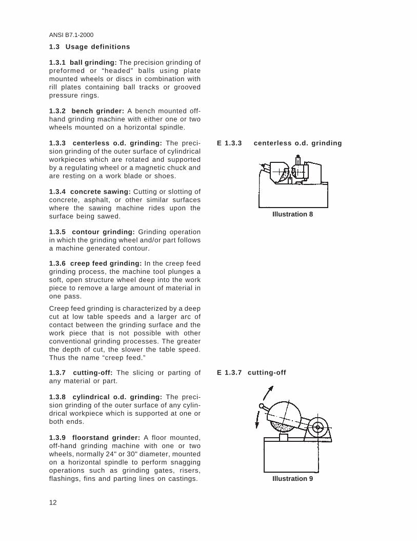
1.3.7 cutting-off: The slicing or parting ofany material or part.
1.3.8 cylindrical o.d. grinding: The preci-sion grinding of the outer surface of any cylin-drical workpiece which is supported at one orboth ends.
1.3.9 floorstand grinder: A floor mounted,off-hand grinding machine with one or twowheels, normally 24" or 30" diameter, mountedon a horizontal spindle to perform snaggingoperations such as grinding gates, risers,flashings, fins and parting lines on castings.
E 1.3.3 centerless o.d. grinding
Illustration 8
E 1.3.7 cutting-off
Illustration 9

13
ANSI B7.1-2000
1.3.10 internal grinding: The precision grind-ing of the inside surface of a hole in aworkpiece.
1.3.11 lapidary: The shaping by cutting-offand/or grinding of precious or semi-preciousgem-like materials.
1.3.12 masonry cutting: Cutting-off, notch-ing or slotting units of brick, tile, block, refrac-tory shapes or similar materials where theworkpiece is brought to the machine.
1.3.13 off-hand grinding: The grinding ofany material or part which is held in theoperator's hand.
1.3.14 pedestal grinder: An off-hand grind-ing machine similar to a bench grinder, havingone or two horizontal spindles for the use ofgrinding wheels and mounted on or otherwiseattached to a floor mounted pedestal.
E 1.3.10 internal grinding
Illustration 10 – Internal grindingof a large bore cylinder
E 1.3.13 off-hand grinding
Illustration 11 – Bench grinderused for off-hand grinding

14
ANSI B7.1-2000
1.3.15 pistol grip pneumatic sander: A popu-lar low cost, high speed, unguarded, lightweight portable tool designed for 5" and smallercoated abrasive discs.
1.3.16 precision grinding: Grinding opera-tions performed by machines used to finishwork parts to specified dimensions and finishrequirements.
1.3.17 regulating wheel: In centerless grind-ing, the workpiece is introduced between twowheels, the grinding wheel and the regulatingwheel, both rotating in the same direction butat different speeds. At the same time, theworkpiece is supported from below by a fixedwork-rest blade. The grinding force compo-nent acting in the horizontal direction forcesthe part against the regulating wheel, whichwill control the part rotation. The part willrotate at the speed of the regulating wheel,times the ratio of the regulating wheel diam-eter over the part diameter. Regulating wheelstypically operate at speeds of 10 to 600 RPM.The regulating wheel controls the rotationalspeed of the workpiece and is not considereda grinding wheel and therefore is not subjectto the design limitations associated with agrinding wheel.
1.3.18 rotary tool (burr) grinding: Forming“file like” cutting surfaces on steel or carbide,either mechanically or off-hand.
E 1.3.15 pistol grip pneumatic sander
Most pistol grip pneumatic sanders are ratedfor 14,000 to 25,000 rpm @ 90 psi., but due tothe ungoverned design of most, if not all ma-chines, speeds in excess of the rated speedare attainable by simply increasing the airpressure and volume. Mounting systems arecomprised of an inner flange for 5" and smallercoated abrasive discs with a concave unre-lieved mounting surface keyed or otherwisepermanently affixed to a direct drive air motor.The outer flange is designed with a 7/8" diam-eter pilot and a convex unrelieved mountingsurface. Herein, the danger lies in that 41/2"through 9" diameter Type 27 wheels and Type28 wheels with a 7/8" hole can be incorrectlymounted on these machines. The high speed,coupled with the lack of a guard, is a recipe fordisaster. UNDER NO CIRCUMSTANCES AREPISTOL GRIP PNEUMATIC SANDERS TO BEUSED WITH GRINDING WHEELS.
E 1.3.17 regulating wheel
Illustration 12 – A schematic drawingof a centerless grinding operation
showing the relationship between theabrasive wheel and regulating wheel

15
ANSI B7.1-2000
1.3.19 saw gumming: The shaping and/orsharpening of saw teeth by grinding.
1.3.20 saws – portable: A machine designedto be hand-held while performing the functionsof sawing with a circular metal blade or cuttingwith a reinforced cutting-off wheel.
1.3.21 slotting: The grinding of a slot orgroove in any material or part.
1.3.22 snagging: Grinding which removesrelatively large amounts of material withoutregard to close tolerances or surface finishrequirements.
1.3.23 surface grinding: The precision grind-ing of a plane surface.
1.3.24 tool and cutter grinding: The preci-sion grinding or sharpening of various types ofmulti-tooth cutters and single point cuttingtools.
1.3.25 tuck pointing: Removal by grinding,of cement, mortar or other nonmetallic jointingmaterial.
E 1.3.19 saw gumming
Illustration 13 – Sharpening teeth (sawgumming) on a large band saw
E 1.3 24 tool and cutter grinding
Illustration 14 – Grinding a shell end mill
E 1.3.25 tuck pointing
Illustration 15 – Tuck pointing using areinforced organic bonded abrasive wheel

16
ANSI B7.1-2000
1.3.26 wall sawing: Cutting or slotting ofconcrete, brick, block or other similar surfaceswhere the sawing machine rides upon a trackwhich is securely bolted to the surface beingsawed.
1.3.27 users of wheels and machines: Anyindividual, person, partnership, corporation orother form of enterprise which uses abrasivewheels and machines.
1.3.28 valve: A device to control the flow ofcoolant, grinding fluid or air.
1.3.29 wheel safety guard:* A wheel guardis an enclosure designed to restrain the piecesof the abrasive wheel and furnish all possibleprotection to personnel in the event that thewheel is broken in operation.
1.4 Definitions and limitations of wheelshapes
The following wheel shape definitions and limi-tations are safety standard recommendationsfor general use and should be used whereverpossible. Wheel dimensions or shapes differ-ing from the standard recommendations belowmay be used on specific machines but shallrequire the approval of the wheel and machinemanufacturer.
1.4.1 Abrasive disc wheels
Definition:
A grinding disc or cylinder used in single ordouble spindle disc grinders, with a shapesimilar to a Type 1 straight wheel or a Type 2cylinder wheel. The entire front side of thedisc is used for grinding. (See sections 3.9,page 39 and 3.10, page 41.)
a. Anchor mounted discs These discs aremounted with bolts or screws to a machinesupporting plate by several means such as,
E 1.3.26 wall sawing
Illustration 16 – Securely mounted wall saw
E 1.4 Definitions and limitations of wheelshapes
Using nonstandard wheels can create specialproblems in mounting, guarding and opera-tion. Therefore, it is advisable for the user toconsult the machine builder and the wheelmanufacturer for their recommendations. Seeannex C for key to letter dimensions.
E 1.4.1 Abrasive discs (wheels)
Illustration 17 – Typical example of the varioustypes of abrasive discs
*Definition taken from ANSI B11.9.

17
ANSI B7.1-2000
but not limited to, imbedded nuts and washersin the back of the disc.
b. Plate mounted discs These discs aremounted to a machine supporting plate by acemented-on steel backplate having tappedholes and/or projecting studs or other meansfor mounting.
1.4.2 Corner clearance (‘C’ dimension)
The corner clearance is defined as the junc-tion between the inner wall of a recess and theflat (‘K’ Dimension).
1.4.3 Recess diameter (‘P’ dimension)
The recess diameter is defined as:
P = K + (2 x C)
See illustration 20.
1.4.4 Type 1 straight wheels
Definition:
Type 1 straight wheels have diameter, thick-ness and hole size dimensions and grindingshould be performed on the periphery. Thisdoes not preclude their use for applicationssuch as shoulder contour and form grindingwhere it is recognized that a limited amount ofside grinding will be performed. Extreme cau-tion should be exercised not to use excessiveside pressure. Type 1 wheels shall be mountedbetween equal flanges of the appropriate de-sign as specified in section 5, page 72.
Limitation:
Hole dimension (H) should not be greater thantwo-thirds of the full size wheel diameter di-mens ion (D) fo r prec is ion, cy l indr ica l ,centerless or surface grinding applications.Maximum hole size for all other applicationsshould not exceed one-half the wheel diam-eter. Inorganic wheels used in snagging op-erations should have a maximum hole size ofnot more than one-quarter of the wheel diam-eter.
E 1.4.4 Type 1 straight wheels
GRINDINGSURFACE
TD
H
Illustration 18 – Type 1 straight wheelPeripheral grinding wheel having a diameter, thick-ness and hole.

18
ANSI B7.1-2000
1.4.5 Type 2 cylinder wheels
Definition:
Type 2 cylinder wheels have diameter, wheelthickness and rim thickness dimensions. Grind-ing shall be performed on the rim surface only,dimension W. Cylinder wheels may be plain,plate mounted, inserted nut or of the project-ing stud type.
Limitation:
Rim height, T dimension, is equal to or greaterthan rim thickness, W dimension.
1.4.6 Type 5 recessed one side wheels
Definition:
Type 5 recessed one side wheels have diam-eter, thickness and hole size dimensions andin addition also have recess diameter anddepth dimensions.
Limitation:
Type 5 wheels are subject to the same limita-tions of hole size, use and mounting as Type1 wheels, definition 1.4.4, above, and sec-tion6, page 87. In addition, recess depth, Fdimension, should not exceed 50% of wheelthickness, T dimension. The inside flat K di-mension, shall be large enough to accommo-date a suitable flange as recommended insection 5, page 72.
1.4.7 Type 6 straight cup wheels
Definition:
Type 6 cup wheels have diameter, thickness,hole size, rim thickness and back thicknessdimensions. Grinding should be performed onrim surface, W dimension.
Limitation:
Minimum back thickness, E dimension, shouldnot be less than 1/4 T dimension. In addition,when unthreaded hole wheels are specified,the inside flat, K dimension, shall be largeenough to accommodate a suitable flange.See flange recommendations, section 5,page72.
E 1.4.5 Type 2 cylinder wheels
T
W
D GRINDINGSURFACE
Illustration 19 – Side grinding wheel having adiameter, thickness and wall
E 1.4.6 Type 5 recessed one side wheels
TEF
H
K
D
PC
GRINDINGSURFACE
Illustration 20 – Type 5 wheel,recessed one side
Peripheral grinding wheel having one side straightor flat and the opposite side recessed. Recessedwheels allow a wider faced abrasive wheel to beused when the available mounting thickness (E) isless than the required overall thickness (T). Therecess allows grinding clearance for the nut andflange.
E 1.4.7 Type 6 straight cup wheels
D
T
W
E
H
GRINDINGSURFACE
P
KC
Illustration 21 – Type 6 straight cup wheelSide grinding wheel having a diameter, thicknessand hole with one side straight or flat and theopposite side recessed. This type, however, differsfrom Type 5 in that the grinding is performed on thewall of the abrasive created by the difference be-tween the diameter of the recess and the outsidediameter of the wheel. Therefore, the wall thick-ness "W" takes precedence over the diameter ofthe recess as an essential intermediate dimensionto describe this shape type.

19
ANSI B7.1-2000
1.4.8 Type 7 double recessed wheels
Definition:
Type 7 double recessed wheels have diam-eter, thickness and hole size dimensions andin addition also have recess diameters anddepth dimensions.
Limitations:
Type 7 wheels are subject to the same limita-tions of hole size, use and mounting, as Type1 wheels, section 1.4.4, page 17, and sec-tion 6, page 87. In addition, the combineddepth of recess F and G dimensions, shouldnot exceed 50% of wheel thickness, T dimen-sion. The inside flat, K dimension, shall belarge enough to accommodate a suitable flangeas recommended in section 5, page 72.
1.4.9 Type 11 flaring cup wheels
Definition:
Type 11 flaring cup wheels have double diam-eter dimensions D and J, and in addition, havethickness, hole size, rim and back thicknessdimensions. Grinding should be performed onrim surface, W dimension.
Limitation:
Type 11 wheels are subject to all limitations ofuse and mounting listed for Type 6 straightsided cup wheels, definition 1.4.7, and sec-tion 6, page 87.
Minimum back thickness, E dimension, shouldnot be less than 1/4 T dimension. In addition,when unthreaded hole wheels are specified,the inside flat, K dimension, shall be largeenough to accommodate a suitable flange.See flange recommendations, section 5,page 72.
E 1.4.8 Type 7 double recessed wheels
TE
F
G
K
D
K
HGRINDINGSURFACE
P
P
C
C
Illustration 22 – Type 7 wheel,recessed two sides
Peripheral grinding wheels having both sides re-cessed to allow grinding clearance for both flangesor recessed so that unusually wide faced wheelsmay be mounted when the available mounting thick-ness (E) is less than the overall thickness (T).
E 1.4.9 Type 11 flaring cup wheels
T
W
E
J
D
K
H
GRINDINGSURFACE
Illustration 23 – Type 11 flaring cup wheelSide grinding wheel having a wall flared or taperedoutward from the back. Wall thickness at the backis normally greater than at the grinding surface.

20
ANSI B7.1-2000
1.4.10 Type 12 dish wheels
Definition:
Type 12 dish wheels have diameter, thick-ness, rim thickness and back thickness di-mension. In addition, Type 12 wheels alwayshave a surface thickness, U dimension. Grind-ing may be performed on both A and U dimen-sions.
Limitation:
Minimum back thickness, E dimension, shouldbe equal to or greater than 1/2 wheel thickness,T dimension, J and K dimensions shall belarge enough to accommodate a suitableflange. See flange recommendations, sec-tion 5, page 72.
1.4.11 Type 13 saucer wheels
Definition:
Type 13 saucer wheels have diameter, thick-ness, hole size and back thickness dimen-sions. Grinding shall be performed on wheelperiphery, U dimensions, only.
Limitation:
J and K dimensions shall be large enough toaccommodate suitable flanges, see section 5,page 72. In addition, wheel thickness shallalways equal E dimension.
E 1.4.11 Type 13 saucer wheels
R
T
U
E
K
D
H
J
GRINDINGSURFACE
R= U2
Illustration 25 – Type 13 saucer wheelPeripheral grinding wheel known as a saucer, dif-fering from a Type 12 in that the cross-section isequal throughout (U=E). The grinding surface isalways half-round with R=U/2.
E 1.4.10 Type 12 dish wheels
T
UA
EH
J
K
D
GRINDINGSURFACE
Illustration 24 – Type 12 dish wheel
Side grinding wheel known as a dish, differing froma Type 11 in that the Type 12 always has a “U”dimension. The “W” dimension of a Type 11 be-comes the “A” dimension of a Type 12. The grind-ing may be performed on both the “A” and “U”surfaces.

21
ANSI B7.1-2000
1.4.12 Types 16, 17, 18, 18R and 19 coneand plug wheels
Definition:
Type 16 cones have a curved side with a noseradius. Type 17 cones have straight sides withor without a nose radius. Type 18 and 18Rplug wheels are cylindrical in shape with ei-ther a square or curved grinding end. Type 19cone wheels are a combination of cone andplug type shapes and are usually specifiedwhere base dimension D in a Type 17 conewould not provide an adequate cross sectionof abrasive. All types of cone and plug wheelsare manufactured with blind hole threadedbushings and may be used on all surfacesexcept the flat mounting surface D.
Limitation:
Cone and plug type wheels are mounted bybeing screwed onto a threaded machinespindle so that surface D seats firmly againstan unrelieved, flat back-up flange. (See sec-tion 3.3.4, page 33.) The maximum volume oftype 16 through 19 cones and plugs shall notbe greater than 35 cubic inches (example: a 3"diameter, 5" thick (T) type 18 plug wheel).Also, the thickness shall not be less than thebase diameter. (Example: a 2" diameter wheelshall not be less than 2" thick.)
Exception:
Valve seat wheels, where the mounting spindleis an integral part of the pilot used to align thewheel with the valve seat surface during grind-ing, need not be mounted as described above.
E 1.4.12 Types 16, 17, 18, 18R and 19cone and plug wheels
Type 16 — Cone, curved side. Type 17 — Cone, straightside, square tip.
Type 18 — Plug, square end. Type 18R — Plug, round end.
Type 19 — Plug, conical end, square tip.
R1 GRINDINGSURFACE
R
H
B
D
T
GRINDINGSURFACE
J
HD
TB
GRINDING SURFACE
DH
TB
RGRINDING SURFACE
DH
BT
GRINDINGSURFACE
HD
JBS
T
Illustration 26 – Various types of cone andplug wheels

22
ANSI B7.1-2000
1.4.13 Types 20, 21, 22, 23, 24, 25, 26relieved and/or recessed wheels
Definition:
Types 20 through 26 relieved and/or recessedwheels have diameter, thickness, hole size,recess diameter and depth dimensions, and inaddition may have tapered relief on one orboth sides.
Limitation:
Types 20 through 26 wheels are subject to thesame limitations of use and mounting as Type1wheels, definition 1.4.4, page 17 and sec-tion 6, page 87.
Tapered relief depths shall be considered asrecesses and added to straight recess depthor depths for determination of total wheel re-cess depth. Total recess depths should notexceed 50% of wheel thickness, T dimension.Dimension K shall be large enough to accom-modate a suitable flange as recommended insection 5, page 72.
1.4.14 Types 27 and 28 depressed centerwheels
Definition:
Types 27 and 28, depressed center wheels,have diameter, thickness and hole size di-mensions. Both types are reinforced, organicbonded wheels having depressed centerswhich permit grinding without interference withthe mounting.
Type 27 wheels are manufactured with flatgrinding rims or faces and are designed forside grinding, when used at a slight angle tothe workpiece, or peripheral grinding, includ-ing small cutting-off and shallow notching op-erations. When grinding masonry and con-crete surfaces, such as ceilings and walls,they may be used flat. Such wheels havedeeper than normal depressed centers for flatblending.
Type 28 wheels have saucer-shaped grindingrims and are designed for corner grinding andside grinding, and shall not be used for cut-ting-off or notching operations.
E 1.4.13 Types 20, 21, 22, 23, 24, 25, 26relieved and/or recessed wheels
Type 20 — Wheel, relieved one side. Type 21 — Wheel, relieved two sides.
Type 22 — Wheel, relieved one side, recessed other side. Type 23 — Wheel, relieved and recessed same side.
Type 24 — Wheel, relieved and recessedone side, recessed other side.
Type 25 — Wheel, relieved and recessedone side, relieved other side.
Type 26 — Wheel, relieved and recessed both sides.K
*
*
aaaaaaaaaaaaaaaaaaaaaaaaaaaaaaTEN
A
O HK
D
K
GRINDINGSURFACE
*aaaaaaaaaaaaaaaaaaaaaaaaaaaaaaGRINDINGSURFACE
T
NFA
E
K
D
H
aaaaaaaaaaaaaaaaaaaaaaaaaaaaaaaaaaaTF N
A
EO
K
K
H
D
GRINDINGSURFACE
*aaaaaaaaaaaaaaaaaaaaaaaaaaaaaaTA
E
FN
GO
D
K
H GRINDINGSURFACE
*
aaaaaaaaaaaaaaaaaaaaaaaaaaaaaaGRINDINGSURFACE
T
NF
E
A
G H
K
K
D
T
EN
A
F
D
K
HK
aaaaaaaaaaaaaaaaaaaaGRINDINGSURFACE
aaaaaaaaaaaaaaaaaaaaGRINDINGSURFACE
T
AN
E
D
H
KaaaaaaaaaaaaaaaaaaaaaaaaaaaaIllustration 27 – Various types of relieved
and/or recessed wheels*For details of relationship between "P" (recessdiameter) and "K" (inside flat) see illustration 20,page 18.
E 1.4.14 Types 27 and 28 depressed cen-ter wheels
Type 27
Type 28
U = E
U
V1E O
K
D
J
HY
GRINDINGSURFACE
GRINDINGSURFACE
U = E
U
OE
K
D
Y
H
Illustration 28 – Types 27 and 28 wheels,depressed center
Wheels are generally used on right angle headportable grinders.

23
ANSI B7.1-2000
Limitation:
Special supporting, back adaptor and insideflange nuts are required for the proper mount-ing of these types of wheels, see section 6.15,page 96.
Mounts which are affixed to the wheel by themanufacturer may not require an inside nutand shall not be reused.
It is the user/owner's responsibility to ensurewheels with this type mount fit inside the guardaccording to section 4.
1.4.15 Type 27 abrasive flap disc wheels
Construction consists of a reinforced organicbonded wheel shape with a depressed centermetal reinforced arbor hole. Grinding portionconsists of abrasive coated cloth pieces whichare layered and glued on the peripheral por-tion of the bottom side.
Common shapes have flat and tapered lay-ered coated abrasive grinding surfaces.
1.4.16 Type 27A depressed center wheels
Definition:
Type 27A depressed center, cutting-off wheelshave diameter, thickness and hole size di-mensions. They are reinforced, organicbonded, offset hub type wheels, usually 16"diameter and larger, specially designed foruse on cutting-off machines where mountingnut or outer flange interference cannot betolerated.
Limitation:
See section 5.1, page 72, and illustration 30for mounting details.
1.4.17 Type 29 wheels
Definition:
Type 29 grinding wheels have reversed sau-cer shaped grinding rims and are designed forblending (stock removal which leaves a smoothfinish). They shall not be used for cutting off ornotching applications.
E 1.4.15 Type 27 abrasive flap disc wheels
GRINDINGSURFACE
Illustration 29 – Type 27 abrasive flap discwheels, tapered and flat grinding surfaces
E 1.4.16 Type 27A depressed centerwheels
Illustration 30 – Type 27A wheel showingtypical mounting details
E 1.4.17 Type 29 wheels
DH
K
GrindingSurface
U
Illustration 31 – Type 29 wheels

24
ANSI B7.1-2000
1.4.18 Cutting-off wheels
Definition:
Cutting-off wheels have diameter, thickness,and hole size dimensions. They may be metalor organic bonded abrasives of the non-rein-forced, reinforced, heavily reinforced or metalcenter type.
(a) Non-reinforced cutting-off wheels are de-signed to withstand only centrifugal, radialand tangential cutting forces in the plane ofthe wheel.
(b) Reinforced cutting-off wheels are strongin the plane of the wheel and are better able towithstand some lateral and twisting forces.
(c) Heavily reinforced wheels have greateramounts of reinforcement than category (b)and are intended for use on heavy duty, highspeed applications where the cutting plane isnot fixed.
(d) Metal centered wheels may be used onany of the aforementioned cutting-off opera-tions.
Limitation:
Cutting-off wheels are subject to all limitationsof mounting and use listed for Type 1 wheels,definition 1.4.4, page 17, and section 6,page 87. In addition, cutting-off wheels arerecommended only for use on specially de-signed and guarded machines and are subjectto the following maximum thickness and holesize limitations.
Wheel Diameter Maximum Thickness4" and Smaller 1/8"Larger than 4" to 6" 3/16"Larger than 6" to 12" 1/4"Larger than 12" to 23" 3/8"Larger than 23" to 48" 1/2"Larger than 48" 5/8"Maximum hole size for cutting-off wheelsshould not be larger than 1/4 wheel diameter.
E 1.4.18 Cutting-off wheels
(a) Wheels with webbing, fabric or filamentaround the flange area only are classified asnon-reinforced wheels. Non-reinforced cutting-off wheels are intended for use on standardspeed machines where the cutting plane iscontrolled and the workpiece is secured toprevent movement. Non-reinforced cutting-offwheels are not designed for use on portablemachines.
(b) Reinforced cutting-off wheels may be usedon the same applications as non-reinforcedwheels as well as other standard speed lowhorsepower applications where the cuttingplane is not fixed such as hand-held portableelectric saws and grinders.
(c) Typical applications for heavily reinforcedcutting-off wheels are swing frame or locked-down-head-chop saws and especially high-speed gasoline powered saws.
(d) Metal centered cutting-off wheels may besteel or powdered metal centers with continu-ous or segmental abrasive rims.
Illustration 32 – A sample of a wet machineused for horizontal cutting-off

25
ANSI B7.1-2000
1.4.19 Mounted wheels
Definition:
Mounted wheels, usually 2" diameter orsmaller, and of various shapes, may be eitherorganic or inorganic bonded abrasive wheels.They are secured to plain or threaded man-drels.
Limitation:
See section 10, page 117, for safe operationand speeds for mounted wheels.
1.4.20 Threaded hole cup wheels
Definition:
Threaded hole cup wheels Types 6 and 11 aredesigned for use on vertical, right angle head,or flexible shaft portable grinders. They haveone central threaded bushing, securely an-chored in place. They are mounted by beingscrewed onto a threaded machine spindle sothat the wheel back seats firmly against anunrelieved flat back flange.
Limitation:
Threaded hole cup wheel mounting should notbe used with wheels larger than 6" diameterfor portable applications. However, it is recog-nized that some swing frame applications dorequire larger than 6" diameter threaded holecup wheels. Back flanges used in mountingthreaded hole cup wheels shall be flat andunrelieved.
1.4.21 Tuck pointing wheels
Definition:
Tuck pointing wheels are Type 1 reinforcedorganic bonded wheels and have diameter,thickness and hole size dimensions.
Limitation:
Tuck pointing wheels are subject to the samelimitations of use and mounting as Type 1wheels, definition 1.4.4, page 17, and sec-tion 6, page 87.
E 1.4.19 Mounted wheels
Illustration 33 – Typical examples of grindingwheels known as mounted wheels
E 1.4.20 Threaded hole cup wheels
Illustration 34 – A cup wheel with a pronganchor bushing (anchor prong bushing)
Illustration 35 – A cup wheelwith a full back bushing

26
ANSI B7.1-2000
1.4.22 Modified Types 6 and 11 wheels(terrazzo)
Definition:
Some Types 6 and 11 cup wheels used in theterrazzo trade have tapered K dimensions tomatch a special tapered flange furnished bythe machine builder.
Limitation:
These wheels shall be mounted only with aspecial tapered flange.
1.5 Abrasive wheels for use on portableair grinding machines
Abrasive wheels for use on portable air grind-ing machines shall conform in type and dimen-sion to the specifications listed in ANSI B186.1Safety Code for Portable Air Tools, latest edi-tion. (For convenience, these wheels are listedin annex C.)
Exception: It is recognized that wheels otherthan those listed exist or may evolve throughtechnology. Such wheels shall be used only ifeither of the following conditions are met:
(1) Where, after consultation and recommen-dation from the wheel manufacturer and thegrinding machine manufacturer, safety provi-sions consistent with this standard are made.
(2) Where the grinding machine is designedand rated for the specific wheel, and propersafety provisions consistent with this standardare used.
E 1.4.22 Modified Types 6 and 11 wheels(terrazzo)
Tapered “K” Dimension Tapered “K” Dimension
Type 6 Wheel (Terrazzo) Type 11 Wheel (Terrazzo)
Illustration 36 – Typical examples ofmodified Types 6 and 11 wheels (terrazzo)
showing tapered K dimensions