Embed Size (px)
Citation preview
FOREWORD
Safety Oversight Compliance Checklist
This document contains a safety oversight compliance checklist for Annex 14 - Aerodromes, Volume I (Aerodrome Design and Operations)[Amendment 8 and
9]. The Compliance Checklist has been prepared to assist the State in ascertaining the status of implementation of Standards and Recommended Practices (SARPs) and in
identifying any difference that may exist between the national regulations and the relevant ICAO Annex provisions.
The compliance checklist is one of the major tools for conducting a safety oversight audit of all Contracting States under the systems approach. As such, all
Contracting States are required to complete the compliance checklist and other related questionnaires within the predetermined period and submit it to ICAO for
evaluation and recording. The compliance checklist will enable Contracting States to identify differences between their own practices and that established by the
international standard (Article 38 of the Convention refers).
The submitted information will also enable ICAO to maintain an up-to-date database on a State‟s level of compliance to the ICAO SARPs, and help to facilitate
the conduct of a standardized audit of all Contracting States. As a result States will obtain a clear picture of the implementation status of the Standards and
Recommended Practices of Annex 14. To ensure currency, States will be requested to update the compliance checklist six months prior to the schedule date of the audit,
which will, make the conduct of the audit on the basis of the most current information possible.
The timely forwarding of the completed checklist to the Safety Oversight Audit Section (SOA) within the prescribed time frame is one of the factors that will
help to ensure an efficient and effective implementation of the comprehensive systems approach for the conduct of the safety oversight audits, as mandated by the 35th
ICAO General Assembly Resolution A35-6 (Oct 2004).
The following categories should be considered as a guide in determining reportable differences:
More exacting or exceeds - This category applies when the national regulation is more exacting than the corresponding ICAO SARPs or by imposing an
obligation within the scope of the Annex which is not covered by an ICAO Standard;
Different in character or other means of compliance - This category applies when the national regulation is different in character from the corresponding ICAO
SARPs or when the national regulations differs in principle, type or system from the corresponding ICAO Standard, without necessarily imposing an additional
obligation;
Less protective or partially implemented / not implemented - This category applies when the national regulation is less protective than the corresponding ICAO
SARPs; or when no national regulation has been promulgated to address the corresponding ICAO SARP, in whole or in part;
Not applicable - This category applies when a Contracting State deems an ICAO SARP related to aircraft, personnel, airways or auxiliary services not applicable
to the prevailing aviation activities of the Contracting State, because uniformity in this case will not facilitate or improve air navigation.

Annex
Reference &
SARP
Identifier
Annex 14 – Volume I Amendment 8 and 9 COSCAP-BAG
Generic
Aerodrome
Standards and
Recommended
Practices
Reference
Difference
Not
Applicable
Text of the
difference
identified by
the State
Comments
including
the reason
for
difference
No
Yes
Aerodromes Level of implementation of SARPs
Aerodrome Design and Operations
Annex Standard or Recommended Practice
More
Exacting
or
Exceeds
Different in
character or
Other
means of
compliance
Less protective or
partially
implemented or
not implemented
QMSF-007-23-I Page 2 of 328
1.1
14-0000001000
Chapter 1 Std.
CHAPTER 1. GENERAL
Definitions
When the following terms are used in this Annex they
have the following meanings:
Accuracy. A degree of conformance between the
estimated or measured value and the true value.
Chapter 1 Std.
1.1
14-0000001200
Chapter 1 Std.
Aerodrome. A defined area on land or water (including
any buildings, installations, and equipment) intended to
be used either wholly or in part for the arrival, departure
and surface movement of aircraft.
1.1
Chapter 1 Std.
1.1
14-0000001400
Chapter 1 Std.
Aerodrome beacon. Aeronautical beacon used to
indicate the location of an aerodrome from the air.
1.1
Chapter 1 Std.
1.1
14-0000001600
Chapter 1 Std.
Aerodrome certificate. A certificate issued by the
appropriate authority under applicable regulations for
the operation of an aerodrome.
1.1
Chapter 1 Std.
1.1
14-0000001800
Chapter 1 Std.
Aerodrome elevation. The elevation of the highest point
of the landing area.
1.1
Chapter 1 Std.
1.1
Aerodrome identification sign. A sign placed on an
aerodrome to aid in identifying the aerodrome from the
1.1
Annex
Reference &
SARP
Identifier
Annex 14 – Volume I Amendment 8 and 9 COSCAP-BAG
Generic
Aerodrome
Standards and
Recommended
Practices
Reference
Difference
Not
Applicable
Text of the
difference
identified by
the State
Comments
including
the reason
for
difference
No
Yes
Aerodromes Level of implementation of SARPs
Aerodrome Design and Operations
Annex Standard or Recommended Practice
More
Exacting
or
Exceeds
Different in
character or
Other
means of
compliance
Less protective or
partially
implemented or
not implemented
QMSF-007-23-I Page 3 of 328
14-0000002000
Chapter 1 Std.
air.
Chapter 1 Std.
1.1
14-0000002200
Chapter 1 Std.
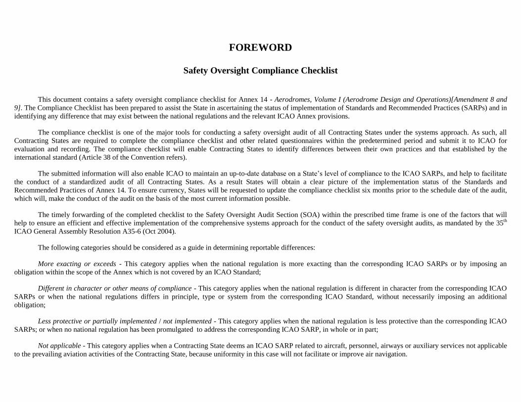
Aerodrome reference point. The designated geographical
location of an aerodrome.
1.1
Chapter 1 Std.
1.1
14-0000002400
Chapter 1 Std.
Aerodrome traffic density.
a) Light. Where the number of movements
in the mean busy hour is not greater than 15 per runway
or typically less than 20 total aerodrome movements.
b) Medium. Where the number of
movements in the mean busy hour is of the order of 16
to 25 per runway or typically between 20 to 35 total
aerodrome movements.
c) Heavy. Where the number of
movements in the mean busy hour is of the order of 26
or more per runway or typically more than 35 total
aerodrome movements.
1.1
Chapter 1 Std.
1.1
14-0000002600
Chapter 1 Std.
Aeronautical beacon. An aeronautical ground light
visible at all azimuths, either continuously or
intermittently, to designate a particular point on the
surface of the earth.
1.1
Chapter 1 Std.
1.1
14-0000002800
Aeronautical ground light. Any light specially provided
as an aid to air navigation, other than a light displayed
1.1

Annex
Reference &
SARP
Identifier
Annex 14 – Volume I Amendment 8 and 9 COSCAP-BAG
Generic
Aerodrome
Standards and
Recommended
Practices
Reference
Difference
Not
Applicable
Text of the
difference
identified by
the State
Comments
including
the reason
for
difference
No
Yes
Aerodromes Level of implementation of SARPs
Aerodrome Design and Operations
Annex Standard or Recommended Practice
More
Exacting
or
Exceeds
Different in
character or
Other
means of
compliance
Less protective or
partially
implemented or
not implemented
QMSF-007-23-I Page 4 of 328
Chapter 1 Std. on an aircraft.
Chapter 1 Std.
1.1
14-0000003000
Chapter 1 Std.
Aeroplane reference field length. The minimum field
length required for take-off at maximum certificated
take-off mass, sea level, standard atmospheric
conditions, still air and zero runway slope, as shown in
the appropriate aeroplane flight manual prescribed by
the certificating authority or equivalent data from the
aeroplane manufacturer. Field length means balanced
field length for aeroplanes, if applicable, or take-off
distance in other cases.
1.1
Chapter 1 Std.
1.1
14-0000003200
Chapter 1 Std.
Aircraft classification number (ACN). A number
expressing the relative effect of an aircraft on a
pavement for a specified standard subgrade category.
1.1
Chapter 1 Std.
1.1
14-0000003400
Chapter 1 Std.
Aircraft stand. A designated area on an apron intended
to be used for parking an aircraft.
1.1
Chapter 1 Std.
1.1
14-0000003600
Chapter 1 Std.
Apron. A defined area, on a land aerodrome, intended to
accommodate aircraft for purposes of loading or
unloading passengers, mail or cargo, fuelling, parking or
maintenance.
1.1
Chapter 1 Std.
1.1
14-0000003800
Chapter 1 Std.
Apron management service. A service provided to
regulate the activities and the movement of aircraft and
vehicles on an apron.
1.1
Chapter 1 Std.
Annex
Reference &
SARP
Identifier
Annex 14 – Volume I Amendment 8 and 9 COSCAP-BAG
Generic
Aerodrome
Standards and
Recommended
Practices
Reference
Difference
Not
Applicable
Text of the
difference
identified by
the State
Comments
including
the reason
for
difference
No
Yes
Aerodromes Level of implementation of SARPs
Aerodrome Design and Operations
Annex Standard or Recommended Practice
More
Exacting
or
Exceeds
Different in
character or
Other
means of
compliance
Less protective or
partially
implemented or
not implemented
QMSF-007-23-I Page 5 of 328
1.1
14-0000003900
Chapter 1 Std.
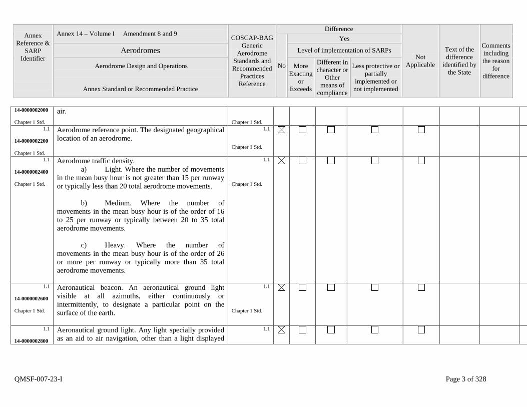
Balked Landing. A landing manoeuvre that is
unexpectedly discontinued at any point below the
obstacle clearance altitude/height (OCA/H).
1.1
Chapter 1 Std.
1.1
14-0000004000
Chapter 1 Std.
Barrette. Three or more aeronautical ground lights
closely spaced in a transverse line so that from a
distance they appear as a short bar of light.
1.1
Chapter 1 Std.
1.1
14-0000004200
Chapter 1 Std.
Calendar. Discrete temporal reference system that
provides the basis for defining temporal position to a
resolution of one day (ISO 19108*).
1.1
Chapter 1 Std.
1.1
14-0000004400
Chapter 1 Std.
Capacitor discharge light. A lamp in which high-
intensity flashes of extremely short duration are
produced by the discharge of electricity at high voltage
through a gas enclosed in a tube.
1.1
Chapter 1 Std.
1.1
14-0000004600
Chapter 1 Std.
Certified aerodrome. An aerodrome whose operator has
been granted an aerodrome certificate.
1.1
Chapter 1 Std.
1.1
14-0000004800
Chapter 1 Std.
Clearway. A defined rectangular area on the ground or
water under the control of the appropriate authority,
selected or prepared as a suitable area over which an
aeroplane may make a portion of its initial climb to a
specified height.
1.1
Chapter 1 Std.
Annex
Reference &
SARP
Identifier
Annex 14 – Volume I Amendment 8 and 9 COSCAP-BAG
Generic
Aerodrome
Standards and
Recommended
Practices
Reference
Difference
Not
Applicable
Text of the
difference
identified by
the State
Comments
including
the reason
for
difference
No
Yes
Aerodromes Level of implementation of SARPs
Aerodrome Design and Operations
Annex Standard or Recommended Practice
More
Exacting
or
Exceeds
Different in
character or
Other
means of
compliance
Less protective or
partially
implemented or
not implemented
QMSF-007-23-I Page 6 of 328
1.1
14-0000005000
Chapter 1 Std.
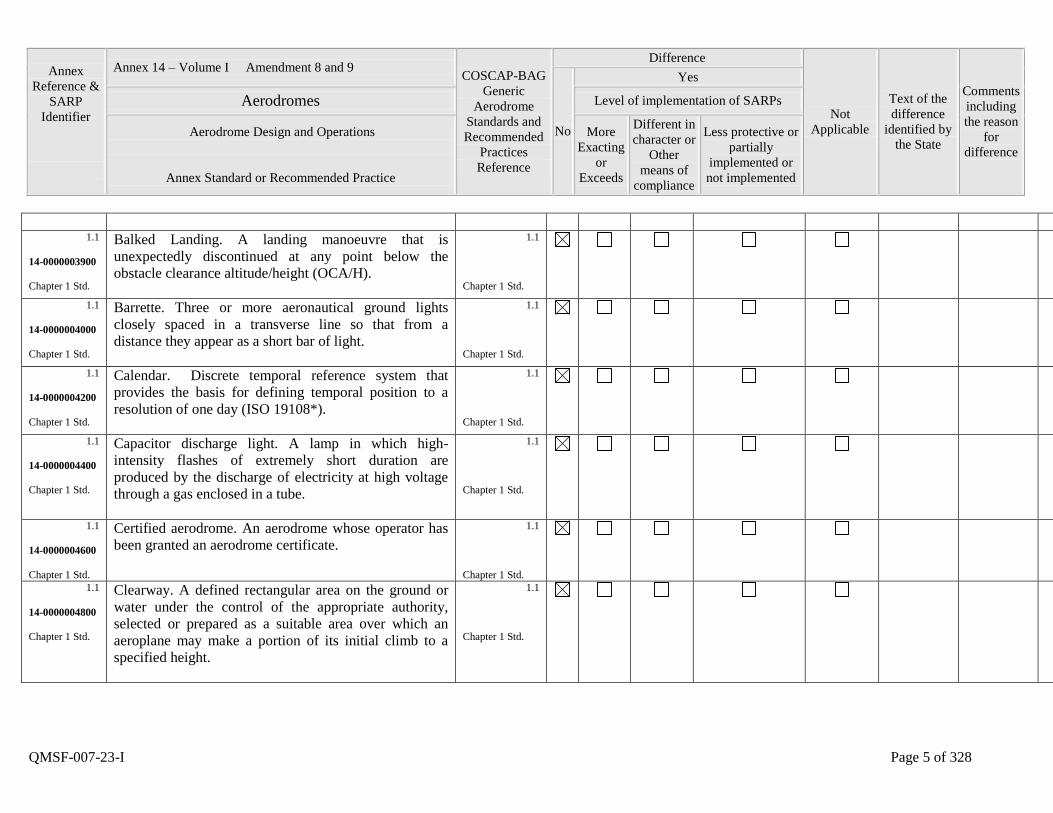
Cyclic redundancy check (CRC). A mathematical
algorithm applied to the digital expression of data that
provides a level of assurance against loss or alteration of
data.
1.1
Chapter 1 Std.
1.1
14-0000005200
Chapter 1 Std.
Data quality. A degree or level of confidence that the
data provided meet the requirements of the data user in
terms of accuracy, resolution and integrity.
1.1
Chapter 1 Std.
1.1
14-0000005400
Chapter 1 Std.
Datum. Any quantity or set of quantities that may serve
as a reference or basis for the calculation of other
quantities (ISO 19104*).
1.1
Chapter 1 Std.
1.1
14-0000005600
Chapter 1 Std.
De-icing/anti-icing facility. A facility where frost, ice or
snow is removed (de-icing) from the aeroplane to
provide clean surfaces, and/or where clean surfaces of
the aeroplane receive protection (anti-icing) against the
formation of frost or ice and accumulation of snow or
slush for a limited period of time.
1.1
Chapter 1 Std.
1.1
14-0000005800
Chapter 1 Std.
De-icing/anti-icing pad. An area comprising an inner
area for the parking of an aeroplane to receive de-
icing/anti-icing treatment and an outer area for the
manoeuvring of two or more mobile de-icing/anti-icing
equipment.
1.1
Chapter 1 Std.
1.1
14-0000006000
Declared distances.
1.1
Annex
Reference &
SARP
Identifier
Annex 14 – Volume I Amendment 8 and 9 COSCAP-BAG
Generic
Aerodrome
Standards and
Recommended
Practices
Reference
Difference
Not
Applicable
Text of the
difference
identified by
the State
Comments
including
the reason
for
difference
No
Yes
Aerodromes Level of implementation of SARPs
Aerodrome Design and Operations
Annex Standard or Recommended Practice
More
Exacting
or
Exceeds
Different in
character or
Other
means of
compliance
Less protective or
partially
implemented or
not implemented
QMSF-007-23-I Page 7 of 328
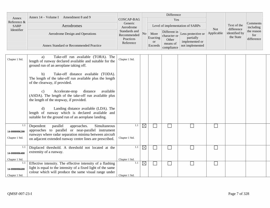
Chapter 1 Std. a) Take-off run available (TORA). The
length of runway declared available and suitable for the
ground run of an aeroplane taking off.
b) Take-off distance available (TODA).
The length of the take-off run available plus the length
of the clearway, if provided.
c) Accelerate-stop distance available
(ASDA). The length of the take-off run available plus
the length of the stopway, if provided.
d) Landing distance available (LDA). The
length of runway which is declared available and
suitable for the ground run of an aeroplane landing.
Chapter 1 Std.
1.1
14-0000006200
Chapter 1 Std.
Dependent parallel approaches. Simultaneous
approaches to parallel or near-parallel instrument
runways where radar separation minima between aircraft
on adjacent extended runway centre lines are prescribed.
1.1
Chapter 1 Std.
1.1
14-0000006400
Chapter 1 Std.
Displaced threshold. A threshold not located at the
extremity of a runway.
1.1
Chapter 1 Std.
1.1
14-0000006600
Chapter 1 Std.
Effective intensity. The effective intensity of a flashing
light is equal to the intensity of a fixed light of the same
colour which will produce the same visual range under
1.1
Chapter 1 Std.
Annex
Reference &
SARP
Identifier
Annex 14 – Volume I Amendment 8 and 9 COSCAP-BAG
Generic
Aerodrome
Standards and
Recommended
Practices
Reference
Difference
Not
Applicable
Text of the
difference
identified by
the State
Comments
including
the reason
for
difference
No
Yes
Aerodromes Level of implementation of SARPs
Aerodrome Design and Operations
Annex Standard or Recommended Practice
More
Exacting
or
Exceeds
Different in
character or
Other
means of
compliance
Less protective or
partially
implemented or
not implemented
QMSF-007-23-I Page 8 of 328
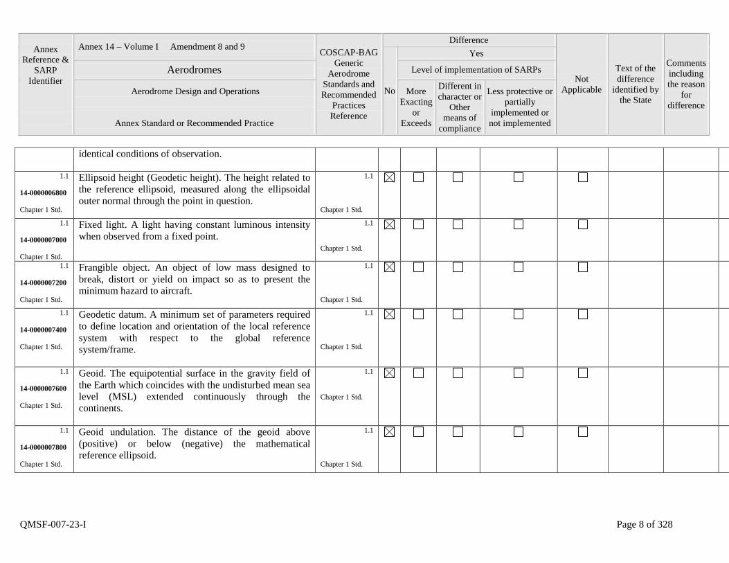
identical conditions of observation.
1.1
14-0000006800
Chapter 1 Std.
Ellipsoid height (Geodetic height). The height related to
the reference ellipsoid, measured along the ellipsoidal
outer normal through the point in question.
1.1
Chapter 1 Std.
1.1
14-0000007000
Chapter 1 Std.
Fixed light. A light having constant luminous intensity
when observed from a fixed point.
1.1
Chapter 1 Std.
1.1
14-0000007200
Chapter 1 Std.
Frangible object. An object of low mass designed to
break, distort or yield on impact so as to present the
minimum hazard to aircraft.
1.1
Chapter 1 Std.
1.1
14-0000007400
Chapter 1 Std.
Geodetic datum. A minimum set of parameters required
to define location and orientation of the local reference
system with respect to the global reference
system/frame.
1.1
Chapter 1 Std.
1.1
14-0000007600
Chapter 1 Std.
Geoid. The equipotential surface in the gravity field of
the Earth which coincides with the undisturbed mean sea
level (MSL) extended continuously through the
continents.
1.1
Chapter 1 Std.
1.1
14-0000007800
Chapter 1 Std.
Geoid undulation. The distance of the geoid above
(positive) or below (negative) the mathematical
reference ellipsoid.
1.1
Chapter 1 Std.
Annex
Reference &
SARP
Identifier
Annex 14 – Volume I Amendment 8 and 9 COSCAP-BAG
Generic
Aerodrome
Standards and
Recommended
Practices
Reference
Difference
Not
Applicable
Text of the
difference
identified by
the State
Comments
including
the reason
for
difference
No
Yes
Aerodromes Level of implementation of SARPs
Aerodrome Design and Operations
Annex Standard or Recommended Practice
More
Exacting
or
Exceeds
Different in
character or
Other
means of
compliance
Less protective or
partially
implemented or
not implemented
QMSF-007-23-I Page 9 of 328
1.1
14-0000008000
Chapter 1 Std.
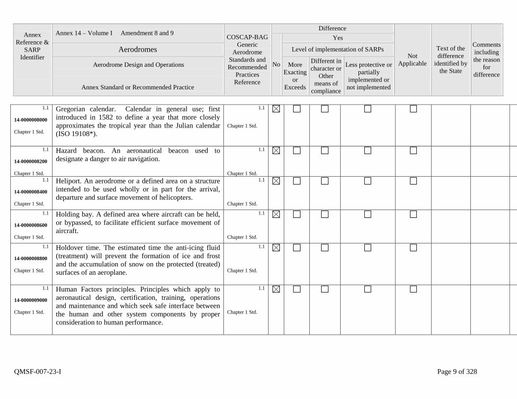
Gregorian calendar. Calendar in general use; first
introduced in 1582 to define a year that more closely
approximates the tropical year than the Julian calendar
(ISO 19108*).
1.1
Chapter 1 Std.
1.1
14-0000008200
Chapter 1 Std.
Hazard beacon. An aeronautical beacon used to
designate a danger to air navigation.
1.1
Chapter 1 Std.
1.1
14-0000008400
Chapter 1 Std.
Heliport. An aerodrome or a defined area on a structure
intended to be used wholly or in part for the arrival,
departure and surface movement of helicopters.
1.1
Chapter 1 Std.
1.1
14-0000008600
Chapter 1 Std.
Holding bay. A defined area where aircraft can be held,
or bypassed, to facilitate efficient surface movement of
aircraft.
1.1
Chapter 1 Std.
1.1
14-0000008800
Chapter 1 Std.
Holdover time. The estimated time the anti-icing fluid
(treatment) will prevent the formation of ice and frost
and the accumulation of snow on the protected (treated)
surfaces of an aeroplane.
1.1
Chapter 1 Std.
1.1
14-0000009000
Chapter 1 Std.
Human Factors principles. Principles which apply to
aeronautical design, certification, training, operations
and maintenance and which seek safe interface between
the human and other system components by proper
consideration to human performance.
1.1
Chapter 1 Std.
Annex
Reference &
SARP
Identifier
Annex 14 – Volume I Amendment 8 and 9 COSCAP-BAG
Generic
Aerodrome
Standards and
Recommended
Practices
Reference
Difference
Not
Applicable
Text of the
difference
identified by
the State
Comments
including
the reason
for
difference
No
Yes
Aerodromes Level of implementation of SARPs
Aerodrome Design and Operations
Annex Standard or Recommended Practice
More
Exacting
or
Exceeds
Different in
character or
Other
means of
compliance
Less protective or
partially
implemented or
not implemented
QMSF-007-23-I Page 10 of 328
1.1
14-0000009200
Chapter 1 Std.
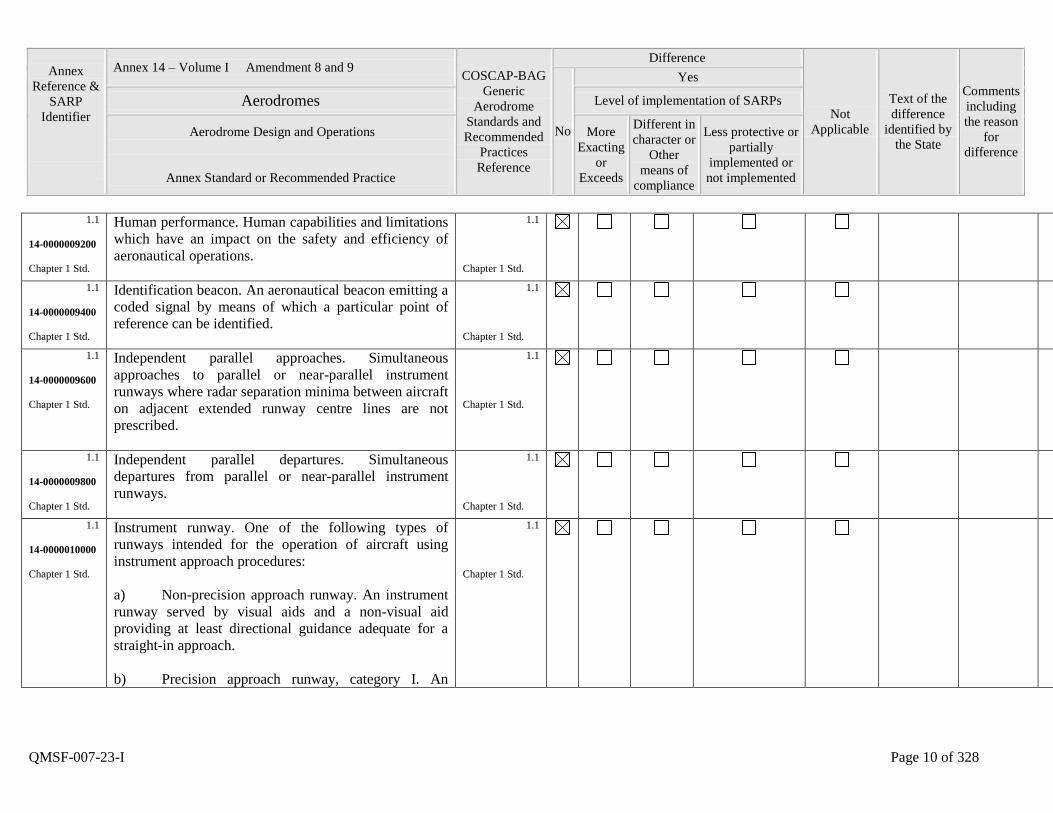
Human performance. Human capabilities and limitations
which have an impact on the safety and efficiency of
aeronautical operations.
1.1
Chapter 1 Std.
1.1
14-0000009400
Chapter 1 Std.
Identification beacon. An aeronautical beacon emitting a
coded signal by means of which a particular point of
reference can be identified.
1.1
Chapter 1 Std.
1.1
14-0000009600
Chapter 1 Std.
Independent parallel approaches. Simultaneous
approaches to parallel or near-parallel instrument
runways where radar separation minima between aircraft
on adjacent extended runway centre lines are not
prescribed.
1.1
Chapter 1 Std.
1.1
14-0000009800
Chapter 1 Std.
Independent parallel departures. Simultaneous
departures from parallel or near-parallel instrument
runways.
1.1
Chapter 1 Std.
1.1
14-0000010000
Chapter 1 Std.
Instrument runway. One of the following types of
runways intended for the operation of aircraft using
instrument approach procedures:
a) Non-precision approach runway. An instrument
runway served by visual aids and a non-visual aid
providing at least directional guidance adequate for a
straight-in approach.
b) Precision approach runway, category I. An
1.1
Chapter 1 Std.

Annex
Reference &
SARP
Identifier
Annex 14 – Volume I Amendment 8 and 9 COSCAP-BAG
Generic
Aerodrome
Standards and
Recommended
Practices
Reference
Difference
Not
Applicable
Text of the
difference
identified by
the State
Comments
including
the reason
for
difference
No
Yes
Aerodromes Level of implementation of SARPs
Aerodrome Design and Operations
Annex Standard or Recommended Practice
More
Exacting
or
Exceeds
Different in
character or
Other
means of
compliance
Less protective or
partially
implemented or
not implemented
QMSF-007-23-I Page 11 of 328
instrument runway served by ILS and/or MLS and visual
aids intended for operations with a decision height not
lower than 60 m (200 ft) and either a visibility not less
than 800 m or a runway visual range not less than 550
m.
c) Precision approach runway, category II. An
instrument runway served by ILS and/or MLS and visual
aids intended for operations with a decision height lower
than 60 m (200 ft) but not lower than 30 m (100 ft) and a
runway visual range not less than 350 m.
d) Precision approach runway, category III. An
instrument runway served by ILS and/or MLS to and
along the surface of the runway and:
A - intended for operations with a
decision height lower than 30 m (100 ft), or no decision
height and a runway visual range not less than 200 m.
B - intended for operations with a
decision height lower than 15 m (50 ft), or no decision
height and a runway visual range less than 200 m but not
less than 50 m.
C - intended for operations with no
decision height and no runway visual range limitations.
Annex
Reference &
SARP
Identifier
Annex 14 – Volume I Amendment 8 and 9 COSCAP-BAG
Generic
Aerodrome
Standards and
Recommended
Practices
Reference
Difference
Not
Applicable
Text of the
difference
identified by
the State
Comments
including
the reason
for
difference
No
Yes
Aerodromes Level of implementation of SARPs
Aerodrome Design and Operations
Annex Standard or Recommended Practice
More
Exacting
or
Exceeds
Different in
character or
Other
means of
compliance
Less protective or
partially
implemented or
not implemented
QMSF-007-23-I Page 12 of 328
1.1
14-0000010200
Chapter 1 Std.
Integrity (aeronautical data). A degree of assurance that
an aeronautical data and its value has not been lost nor
altered since the data origination or authorized
amendment.
1.1
Chapter 1 Std.
1.1
14-0000010400
Chapter 1 Std.
Intermediate holding position. A designated position
intended for traffic control at which taxiing aircraft and
vehicles shall stop and hold until further cleared to
proceed, when so instructed by the aerodrome control
tower.
1.1
Chapter 1 Std.
1.1
14-0000010600
Chapter 1 Std.
Landing area. That part of a movement area intended for
the landing or take-off of aircraft.
1.1
Chapter 1 Std.
1.1
14-0000010800
Chapter 1 Std.
Landing direction indicator. A device to indicate
visually the direction currently designated for landing
and for take-off.
1.1
Chapter 1 Std.
1.1
14-0000011000
Chapter 1 Std.
Laser-beam critical flight zone (LCFZ). Airspace in the
proximity of an aerodrome but beyond the LFFZ where
the irradiance is restricted to a level unlikely to cause
glare effects.
1.1
Chapter 1 Std.
1.1
14-0000011200
Chapter 1 Std.
Laser-beam free flight zone (LFFZ). Airspace in the
immediate proximity to the aerodrome where the
irradiance is restricted to a level unlikely to cause any
visual disruption.
1.1
Chapter 1 Std.
Annex
Reference &
SARP
Identifier
Annex 14 – Volume I Amendment 8 and 9 COSCAP-BAG
Generic
Aerodrome
Standards and
Recommended
Practices
Reference
Difference
Not
Applicable
Text of the
difference
identified by
the State
Comments
including
the reason
for
difference
No
Yes
Aerodromes Level of implementation of SARPs
Aerodrome Design and Operations
Annex Standard or Recommended Practice
More
Exacting
or
Exceeds
Different in
character or
Other
means of
compliance
Less protective or
partially
implemented or
not implemented
QMSF-007-23-I Page 13 of 328
1.1
14-0000011400
Chapter 1 Std.
Laser-beam sensitive flight zone (LSFZ). Airspace
outside, and not necessarily contiguous with, the LFFZ
and LCFZ where the irradiance is restricted to a level
unlikely to cause flash-blindness or after-image effects.
1.1
Chapter 1 Std.
1.1
14-0000011600
Chapter 1 Std.
Lighting system reliability. The probability that the
complete installation operates within the specified
tolerances and that the system is operationally usable.
1.1
Chapter 1 Std.
1.1
14-0000011800
Chapter 1 Std.
Manoeuvring area. That part of an aerodrome to be used
for the take-off, landing and taxiing of aircraft,
excluding aprons.
1.1
Chapter 1 Std.
1.1
14-0000012000
Chapter 1 Std.
Marker. An object displayed above ground level in order
to indicate an obstacle or delineate a boundary.
1.1
Chapter 1 Std.
1.1
14-0000012200
Chapter 1 Std.
Marking. A symbol or group of symbols displayed on
the surface of the movement area in order to convey
aero-nautical information.
1.1
Chapter 1 Std.
1.1
14-0000012400
Chapter 1 Std.
Movement area. That part of an aerodrome to be used
for the take-off, landing and taxiing of aircraft,
consisting of the manoeuvring area and the apron(s).
1.1
Chapter 1 Std.
1.1
14-0000012600
Near-parallel runways. Non-intersecting runways whose
extended centre lines have an angle of
1.1
Annex
Reference &
SARP
Identifier
Annex 14 – Volume I Amendment 8 and 9 COSCAP-BAG
Generic
Aerodrome
Standards and
Recommended
Practices
Reference
Difference
Not
Applicable
Text of the
difference
identified by
the State
Comments
including
the reason
for
difference
No
Yes
Aerodromes Level of implementation of SARPs
Aerodrome Design and Operations
Annex Standard or Recommended Practice
More
Exacting
or
Exceeds
Different in
character or
Other
means of
compliance
Less protective or
partially
implemented or
not implemented
QMSF-007-23-I Page 14 of 328
Chapter 1 Std. convergence/divergence of 15 degrees or less.
Chapter 1 Std.
1.1
14-0000012800
Chapter 1 Std.
Non-instrument runway. A runway intended for the
operation of aircraft using visual approach procedures.
1.1
Chapter 1 Std.
1.1
14-0000013000
Chapter 1 Std.
Normal flight zone (NFZ). Airspace not defined as
LFFZ, LCFZ or LSFZ but which must be protected from
laser radiation capable of causing biological damage to
the eye.
1.1
Chapter 1 Std.
1.1
14-0000013200
Chapter 1 Std.
Obstacle. All fixed (whether temporary or permanent)
and mobile objects, or parts thereof, that are located on
an area intended for the surface movement of aircraft or
that extend above a defined surface intended to protect
aircraft in flight.
1.1
Chapter 1 Std.
1.1
14-0000013400
Chapter 1 Std.
Obstacle free zone (OFZ). The airspace above the inner
approach surface, inner transitional surfaces, and balked
landing surface and that portion of the strip bounded by
these surfaces, which is not penetrated by any fixed
obstacle other than a low-mass and frangibly mounted
one required for air navigation purposes.
1.1
Chapter 1 Std.
1.1
14-0000013600
Chapter 1 Std.
Orthometric height. Height of a point related to the
geoid, generally presented as an MSL elevation.
1.1
Chapter 1 Std.
Annex
Reference &
SARP
Identifier
Annex 14 – Volume I Amendment 8 and 9 COSCAP-BAG
Generic
Aerodrome
Standards and
Recommended
Practices
Reference
Difference
Not
Applicable
Text of the
difference
identified by
the State
Comments
including
the reason
for
difference
No
Yes
Aerodromes Level of implementation of SARPs
Aerodrome Design and Operations
Annex Standard or Recommended Practice
More
Exacting
or
Exceeds
Different in
character or
Other
means of
compliance
Less protective or
partially
implemented or
not implemented
QMSF-007-23-I Page 15 of 328
1.1
14-0000013800
Chapter 1 Std.
Pavement classification number (PCN). A number
expressing the bearing strength of a pavement for
unrestricted operations.
1.1
Chapter 1 Std.
1.1
14-0000014000
Chapter 1 Std.
Precision approach runway, see Instrument runway.
1.1
Chapter 1 Std.
1.1
14-0000014200
Chapter 1 Std.
Primary runway(s). Runway(s) used in preference to
others whenever conditions permit.
1.1
Chapter 1 Std.
1.1
14-0000014400
Chapter 1 Std.
Protected flight zones. Airspace specifically designated
to mitigate the hazardous effects of laser radiation.
1.1
Chapter 1 Std.
1.1
14-0000014600
Chapter 1 Std.
Road. An established surface route on the movement
area meant for the exclusive use of vehicles.
1.1
Chapter 1 Std.
1.1
14-0000014800
Chapter 1 Std.
Road-holding position. A designated position at which
vehicles may be required to hold.
1.1
Chapter 1 Std.
1.1
14-0000015000
Chapter 1 Std.
Runway. A defined rectangular area on a land
aerodrome prepared for the landing and take-off of
aircraft.
1.1
Chapter 1 Std.
1.1
Runway end safety area (RESA). An area symmetrical
about the extended runway centre line and adjacent to
1.1
Annex
Reference &
SARP
Identifier
Annex 14 – Volume I Amendment 8 and 9 COSCAP-BAG
Generic
Aerodrome
Standards and
Recommended
Practices
Reference
Difference
Not
Applicable
Text of the
difference
identified by
the State
Comments
including
the reason
for
difference
No
Yes
Aerodromes Level of implementation of SARPs
Aerodrome Design and Operations
Annex Standard or Recommended Practice
More
Exacting
or
Exceeds
Different in
character or
Other
means of
compliance
Less protective or
partially
implemented or
not implemented
QMSF-007-23-I Page 16 of 328
14-0000015200
Chapter 1 Std.
the end of the strip primarily intended to reduce the risk
of damage to an aeroplane undershooting or overrunning
the runway.
Chapter 1 Std.
1.1
14-0000015400
Chapter 1 Std.
Runway guard lights. A light system intended to caution
pilots or vehicle drivers that they are about to enter an
active runway.
1.1
Chapter 1 Std.
1.1
14-0000015600
Chapter 1 Std.
Runway-holding position. A designated position
intended to protect a runway, an obstacle limitation
surface, or an ILS/MLS critical/sensitive area at which
taxiing aircraft and vehicles shall stop and hold, unless
otherwise authorized by the aerodrome control tower.
1.1
Chapter 1 Std.
1.1
14-0000015800
Chapter 1 Std.
Runway strip. A defined area including the runway and
stopway, if provided, intended:
a) to reduce the risk of damage to aircraft
running off a runway; and
b) to protect aircraft flying over it during
take-off or landing operations.
1.1
Chapter 1 Std.
1.1
14-0000016000
Chapter 1 Std.
Runway turn pad. A defined area on a land aerodrome
adjacent to a runway for the purpose of completing a
180-degree turn on a runway.
1.1
Chapter 1 Std.
1.1 Runway visual range (RVR). The range over which the 1.1
Annex
Reference &
SARP
Identifier
Annex 14 – Volume I Amendment 8 and 9 COSCAP-BAG
Generic
Aerodrome
Standards and
Recommended
Practices
Reference
Difference
Not
Applicable
Text of the
difference
identified by
the State
Comments
including
the reason
for
difference
No
Yes
Aerodromes Level of implementation of SARPs
Aerodrome Design and Operations
Annex Standard or Recommended Practice
More
Exacting
or
Exceeds
Different in
character or
Other
means of
compliance
Less protective or
partially
implemented or
not implemented
QMSF-007-23-I Page 17 of 328
14-0000016200
Chapter 1 Std.
pilot of an aircraft on the centre line of a runway can see
the runway surface markings or the lights delineating the
runway or identifying its centre line.
Chapter 1 Std.
1.1
14-0000016300
Chapter 1 Std.
Safety programme. An integrated set of regulations and
activities aimed at improving safety.
1.1
Chapter 1 Std.
1.1
14-0000016400
Chapter 1 Std.
Safety management system. A systematic approach to
managing safety including the necessary organizational
structure, accountabilities, policies and procedures.
1.1
Chapter 1 Std.
1.1
14-0000016600
Chapter 1 Std.
Segregated parallel operations. Simultaneous operations
on parallel or near-parallel instrument runways in which
one runway is used exclusively for approaches and the
other runway is used exclusively for departures.
1.1
Chapter 1 Std.
1.1
14-0000016800
Chapter 1 Std.
Shoulder. An area adjacent to the edge of a pavement so
prepared as to provide a transition between the pavement
and the adjacent surface.
1.1
Chapter 1 Std.
1.1
14-0000017000
Chapter 1 Std.
Sign.
a) Fixed message sign. A sign presenting
only one message.
b) Variable message sign. A sign capable
of presenting several pre-determined messages or no
message, as applicable.
1.1
Chapter 1 Std.
Annex
Reference &
SARP
Identifier
Annex 14 – Volume I Amendment 8 and 9 COSCAP-BAG
Generic
Aerodrome
Standards and
Recommended
Practices
Reference
Difference
Not
Applicable
Text of the
difference
identified by
the State
Comments
including
the reason
for
difference
No
Yes
Aerodromes Level of implementation of SARPs
Aerodrome Design and Operations
Annex Standard or Recommended Practice
More
Exacting
or
Exceeds
Different in
character or
Other
means of
compliance
Less protective or
partially
implemented or
not implemented
QMSF-007-23-I Page 18 of 328
1.1
14-0000017200
Chapter 1 Std.
Signal area. An area on an aerodrome used for the
display of ground signals.
1.1
Chapter 1 Std.
1.1
14-0000017400
Chapter 1 Std.
Slush. Water-saturated snow which with a heel-and-toe
slap-down motion against the ground will be displaced
with a splatter; specific gravity: 0.5 up to 0.8.
1.1
Chapter 1 Std.
1.1
14-0000017600
Chapter 1 Std.
Snow (on the ground).
a) Dry snow. Snow which can be blown if
loose or, if compacted by hand, will fall apart again
upon release; specific gravity: up to but not including
0.35.
b) Wet snow. Snow which, if compacted
by hand, will stick together and tend to or form a
snowball; specific gravity: 0.35 up to but not including
0.5.
c) Compacted snow. Snow which has been
compressed into a solid mass that resists further
compression and will hold together or break up into
lumps if picked up; specific gravity: 0.5 and over.
1.1
Chapter 1 Std.
1.1
14-0000017800
Chapter 1 Std.
Station declination. An alignment variation between the
zero degree radial of a VOR and true north, determined
at the time the VOR station is calibrated.
1.1
Chapter 1 Std.
Annex
Reference &
SARP
Identifier
Annex 14 – Volume I Amendment 8 and 9 COSCAP-BAG
Generic
Aerodrome
Standards and
Recommended
Practices
Reference
Difference
Not
Applicable
Text of the
difference
identified by
the State
Comments
including
the reason
for
difference
No
Yes
Aerodromes Level of implementation of SARPs
Aerodrome Design and Operations
Annex Standard or Recommended Practice
More
Exacting
or
Exceeds
Different in
character or
Other
means of
compliance
Less protective or
partially
implemented or
not implemented
QMSF-007-23-I Page 19 of 328
1.1
14-0000018000
Chapter 1 Std.
Stopway. A defined rectangular area on the ground at
the end of take-off run available prepared as a suitable
area in which an aircraft can be stopped in the case of an
abandoned take-off.
1.1
Chapter 1 Std.
1.1
14-0000018200
Chapter 1 Std.
Switch-over time (light). The time required for the actual
intensity of a light measured in a given direction to fall
from 50 per cent and recover to 50 per cent during a
power supply changeover, when the light is being
operated at intensities of 25 per cent or above.
1.1
Chapter 1 Std.
1.1
14-0000018400
Chapter 1 Std.
Take-off runway. A runway intended for take-off only.
1.1
Chapter 1 Std.
1.1
14-0000018600
Chapter 1 Std.
Taxiway. A defined path on a land aerodrome
established for the taxiing of aircraft and intended to
provide a link between one part of the aerodrome and
another, including:
a) Aircraft stand taxilane. A portion of an
apron designated as a taxiway and intended to provide
access to aircraft stands only.
b) Apron taxiway. A portion of a taxiway
system located on an apron and intended to provide a
through taxi route across the apron.
1.1
Chapter 1 Std.
Annex
Reference &
SARP
Identifier
Annex 14 – Volume I Amendment 8 and 9 COSCAP-BAG
Generic
Aerodrome
Standards and
Recommended
Practices
Reference
Difference
Not
Applicable
Text of the
difference
identified by
the State
Comments
including
the reason
for
difference
No
Yes
Aerodromes Level of implementation of SARPs
Aerodrome Design and Operations
Annex Standard or Recommended Practice
More
Exacting
or
Exceeds
Different in
character or
Other
means of
compliance
Less protective or
partially
implemented or
not implemented
QMSF-007-23-I Page 20 of 328
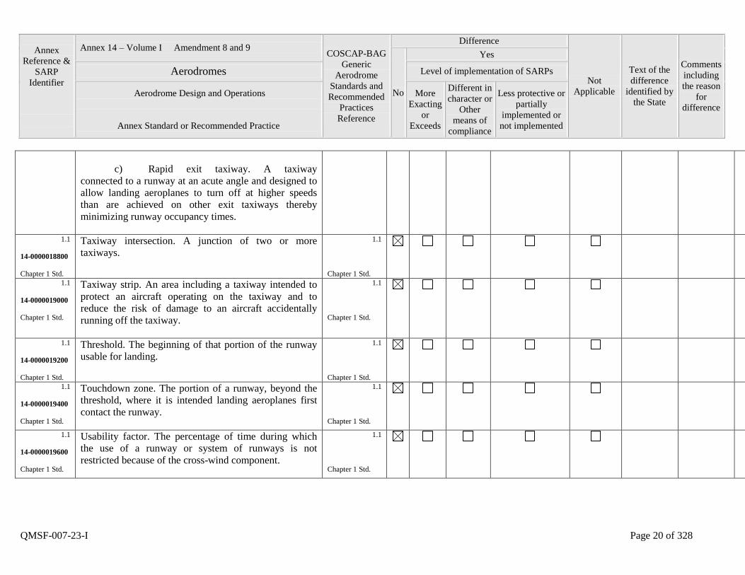
c) Rapid exit taxiway. A taxiway
connected to a runway at an acute angle and designed to
allow landing aeroplanes to turn off at higher speeds
than are achieved on other exit taxiways thereby
minimizing runway occupancy times.
1.1
14-0000018800
Chapter 1 Std.
Taxiway intersection. A junction of two or more
taxiways.
1.1
Chapter 1 Std.
1.1
14-0000019000
Chapter 1 Std.
Taxiway strip. An area including a taxiway intended to
protect an aircraft operating on the taxiway and to
reduce the risk of damage to an aircraft accidentally
running off the taxiway.
1.1
Chapter 1 Std.
1.1
14-0000019200
Chapter 1 Std.
Threshold. The beginning of that portion of the runway
usable for landing.
1.1
Chapter 1 Std.
1.1
14-0000019400
Chapter 1 Std.
Touchdown zone. The portion of a runway, beyond the
threshold, where it is intended landing aeroplanes first
contact the runway.
1.1
Chapter 1 Std.
1.1
14-0000019600
Chapter 1 Std.
Usability factor. The percentage of time during which
the use of a runway or system of runways is not
restricted because of the cross-wind component.
1.1
Chapter 1 Std.
Annex
Reference &
SARP
Identifier
Annex 14 – Volume I Amendment 8 and 9 COSCAP-BAG
Generic
Aerodrome
Standards and
Recommended
Practices
Reference
Difference
Not
Applicable
Text of the
difference
identified by
the State
Comments
including
the reason
for
difference
No
Yes
Aerodromes Level of implementation of SARPs
Aerodrome Design and Operations
Annex Standard or Recommended Practice
More
Exacting
or
Exceeds
Different in
character or
Other
means of
compliance
Less protective or
partially
implemented or
not implemented
QMSF-007-23-I Page 21 of 328
1.2.1
14-0000019800
Chapter 1 Std.
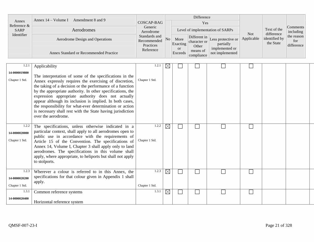
Applicability
The interpretation of some of the specifications in the
Annex expressly requires the exercising of discretion,
the taking of a decision or the performance of a function
by the appropriate authority. In other specifications, the
expression appropriate authority does not actually
appear although its inclusion is implied. In both cases,
the responsibility for what-ever determination or action
is necessary shall rest with the State having jurisdiction
over the aerodrome.
1.2.1
Chapter 1 Std.
1.2.2
14-0000020000
Chapter 1 Std.
The specifications, unless otherwise indicated in a
particular context, shall apply to all aerodromes open to
public use in accordance with the requirements of
Article 15 of the Convention. The specifications of
Annex 14, Volume I, Chapter 3 shall apply only to land
aerodromes. The specifications in this volume shall
apply, where appropriate, to heliports but shall not apply
to stolports.
1.2.2
Chapter 1 Std.
1.2.3
14-0000020200
Chapter 1 Std.
Wherever a colour is referred to in this Annex, the
specifications for that colour given in Appendix 1 shall
apply.
1.2.3
Chapter 1 Std.
1.3.1
14-0000020400
Common reference systems
Horizontal reference system
1.3.1
Annex
Reference &
SARP
Identifier
Annex 14 – Volume I Amendment 8 and 9 COSCAP-BAG
Generic
Aerodrome
Standards and
Recommended
Practices
Reference
Difference
Not
Applicable
Text of the
difference
identified by
the State
Comments
including
the reason
for
difference
No
Yes
Aerodromes Level of implementation of SARPs
Aerodrome Design and Operations
Annex Standard or Recommended Practice
More
Exacting
or
Exceeds
Different in
character or
Other
means of
compliance
Less protective or
partially
implemented or
not implemented
QMSF-007-23-I Page 22 of 328
Chapter 1 Std.
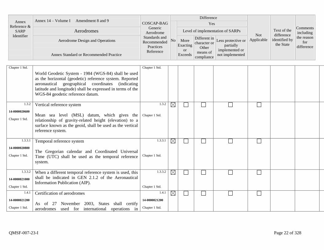
World Geodetic System - 1984 (WGS-84) shall be used
as the horizontal (geodetic) reference system. Reported
aeronautical geographical coordinates (indicating
latitude and longitude) shall be expressed in terms of the
WGS-84 geodetic reference datum.
Chapter 1 Std.
1.3.2
14-0000020600
Chapter 1 Std.
Vertical reference system
Mean sea level (MSL) datum, which gives the
relationship of gravity-related height (elevation) to a
surface known as the geoid, shall be used as the vertical
reference system.
1.3.2
Chapter 1 Std.
1.3.3.1
14-0000020800
Chapter 1 Std.
Temporal reference system
The Gregorian calendar and Coordinated Universal
Time (UTC) shall be used as the temporal reference
system.
1.3.3.1
Chapter 1 Std.
1.3.3.2
14-0000021000
Chapter 1 Std.
When a different temporal reference system is used, this
shall be indicated in GEN 2.1.2 of the Aeronautical
Information Publication (AIP).
1.3.3.2
Chapter 1 Std.
1.4.1
14-0000021200
Chapter 1 Std.
Certification of aerodromes
As of 27 November 2003, States shall certify
aerodromes used for international operations in
1.4.1
14-0000021200
Chapter 1 Std.
Annex
Reference &
SARP
Identifier
Annex 14 – Volume I Amendment 8 and 9 COSCAP-BAG
Generic
Aerodrome
Standards and
Recommended
Practices
Reference
Difference
Not
Applicable
Text of the
difference
identified by
the State
Comments
including
the reason
for
difference
No
Yes
Aerodromes Level of implementation of SARPs
Aerodrome Design and Operations
Annex Standard or Recommended Practice
More
Exacting
or
Exceeds
Different in
character or
Other
means of
compliance
Less protective or
partially
implemented or
not implemented
QMSF-007-23-I Page 23 of 328
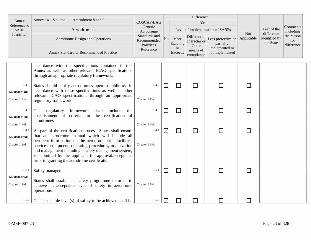
accordance with the specifications contained in this
Annex as well as other relevant ICAO specifications
through an appropriate regulatory framework.
1.4.2
14-0000021400
Chapter 1 Rec.
States should certify aero-dromes open to public use in
accordance with these specifications as well as other
relevant ICAO specifications through an appropriate
regulatory framework.
1.4.2
Chapter 1 Rec.
1.4.3
14-0000021600
Chapter 1 Std.
The regulatory framework shall include the
establishment of criteria for the certification of
aerodromes.
1.4.3
Chapter 1 Std.
1.4.4
14-0000022000
Chapter 1 Std.
As part of the certification process, States shall ensure
that an aerodrome manual which will include all
pertinent information on the aerodrome site, facilities,
services, equipment, operating procedures, organization
and management including a safety management system,
is submitted by the applicant for approval/acceptance
prior to granting the aerodrome certificate.
1.4.4
Chapter 1 Std.
1.5.1
14-0000022240
Chapter 1 Std.
Safety management
States shall establish a safety programme in order to
achieve an acceptable level of safety in aerodrome
operations.
1.5.1
Chapter 1 Std.
1.5.2 The acceptable level(s) of safety to be achieved shall be 1.5.2
Annex
Reference &
SARP
Identifier
Annex 14 – Volume I Amendment 8 and 9 COSCAP-BAG
Generic
Aerodrome
Standards and
Recommended
Practices
Reference
Difference
Not
Applicable
Text of the
difference
identified by
the State
Comments
including
the reason
for
difference
No
Yes
Aerodromes Level of implementation of SARPs
Aerodrome Design and Operations
Annex Standard or Recommended Practice
More
Exacting
or
Exceeds
Different in
character or
Other
means of
compliance
Less protective or
partially
implemented or
not implemented
QMSF-007-23-I Page 24 of 328
14-0000022280
Chapter 1 Std.
established by the State(s) concerned.
Chapter 1 Std.
1.5.3
14-0000022320
Chapter 1 Std.
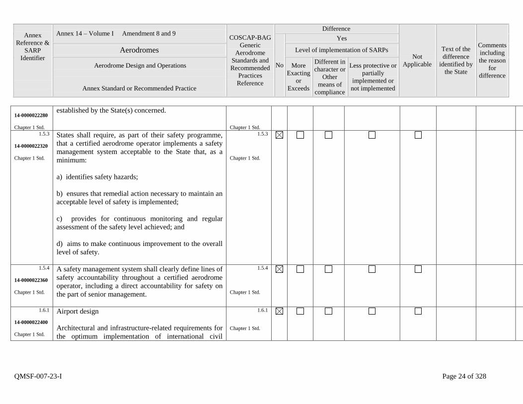
States shall require, as part of their safety programme,
that a certified aerodrome operator implements a safety
management system acceptable to the State that, as a
minimum:
a) identifies safety hazards;
b) ensures that remedial action necessary to maintain an
acceptable level of safety is implemented;
c) provides for continuous monitoring and regular
assessment of the safety level achieved; and
d) aims to make continuous improvement to the overall
level of safety.
1.5.3
Chapter 1 Std.
1.5.4
14-0000022360
Chapter 1 Std.
A safety management system shall clearly define lines of
safety accountability throughout a certified aerodrome
operator, including a direct accountability for safety on
the part of senior management.
1.5.4
Chapter 1 Std.
1.6.1
14-0000022400
Chapter 1 Std.
Airport design
Architectural and infrastructure-related requirements for
the optimum implementation of international civil
1.6.1
Chapter 1 Std.
Annex
Reference &
SARP
Identifier
Annex 14 – Volume I Amendment 8 and 9 COSCAP-BAG
Generic
Aerodrome
Standards and
Recommended
Practices
Reference
Difference
Not
Applicable
Text of the
difference
identified by
the State
Comments
including
the reason
for
difference
No
Yes
Aerodromes Level of implementation of SARPs
Aerodrome Design and Operations
Annex Standard or Recommended Practice
More
Exacting
or
Exceeds
Different in
character or
Other
means of
compliance
Less protective or
partially
implemented or
not implemented
QMSF-007-23-I Page 25 of 328
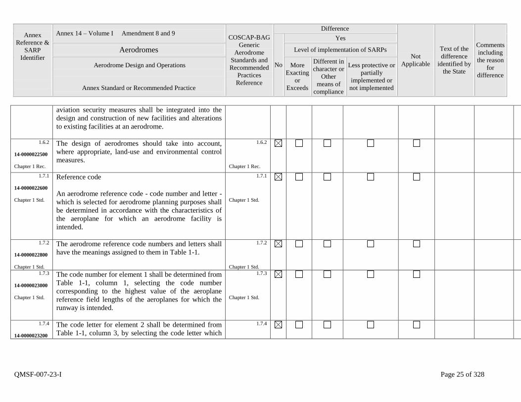
aviation security measures shall be integrated into the
design and construction of new facilities and alterations
to existing facilities at an aerodrome.
1.6.2
14-0000022500
Chapter 1 Rec.
The design of aerodromes should take into account,
where appropriate, land-use and environmental control
measures.
1.6.2
Chapter 1 Rec.
1.7.1
14-0000022600
Chapter 1 Std.
Reference code
An aerodrome reference code - code number and letter -
which is selected for aerodrome planning purposes shall
be determined in accordance with the characteristics of
the aeroplane for which an aerodrome facility is
intended.
1.7.1
Chapter 1 Std.
1.7.2
14-0000022800
Chapter 1 Std.
The aerodrome reference code numbers and letters shall
have the meanings assigned to them in Table 1-1.
1.7.2
Chapter 1 Std.
1.7.3
14-0000023000
Chapter 1 Std.
The code number for element 1 shall be determined from
Table 1-1, column 1, selecting the code number
corresponding to the highest value of the aeroplane
reference field lengths of the aeroplanes for which the
runway is intended.
1.7.3
Chapter 1 Std.
1.7.4
14-0000023200
The code letter for element 2 shall be determined from
Table 1-1, column 3, by selecting the code letter which
1.7.4
Annex
Reference &
SARP
Identifier
Annex 14 – Volume I Amendment 8 and 9 COSCAP-BAG
Generic
Aerodrome
Standards and
Recommended
Practices
Reference
Difference
Not
Applicable
Text of the
difference
identified by
the State
Comments
including
the reason
for
difference
No
Yes
Aerodromes Level of implementation of SARPs
Aerodrome Design and Operations
Annex Standard or Recommended Practice
More
Exacting
or
Exceeds
Different in
character or
Other
means of
compliance
Less protective or
partially
implemented or
not implemented
QMSF-007-23-I Page 26 of 328
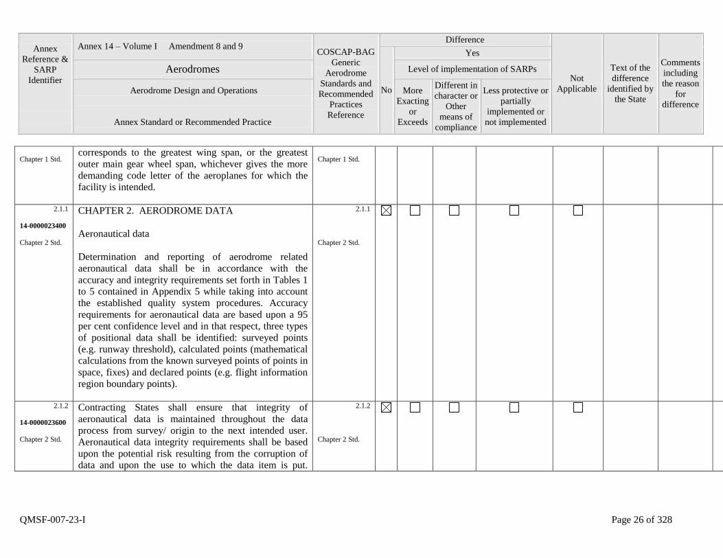
Chapter 1 Std. corresponds to the greatest wing span, or the greatest
outer main gear wheel span, whichever gives the more
demanding code letter of the aeroplanes for which the
facility is intended.
Chapter 1 Std.
2.1.1
14-0000023400
Chapter 2 Std.
CHAPTER 2. AERODROME DATA
Aeronautical data
Determination and reporting of aerodrome related
aeronautical data shall be in accordance with the
accuracy and integrity requirements set forth in Tables 1
to 5 contained in Appendix 5 while taking into account
the established quality system procedures. Accuracy
requirements for aeronautical data are based upon a 95
per cent confidence level and in that respect, three types
of positional data shall be identified: surveyed points
(e.g. runway threshold), calculated points (mathematical
calculations from the known surveyed points of points in
space, fixes) and declared points (e.g. flight information
region boundary points).
2.1.1
Chapter 2 Std.
2.1.2
14-0000023600
Chapter 2 Std.
Contracting States shall ensure that integrity of
aeronautical data is maintained throughout the data
process from survey/ origin to the next intended user.
Aeronautical data integrity requirements shall be based
upon the potential risk resulting from the corruption of
data and upon the use to which the data item is put.
2.1.2
Chapter 2 Std.
Annex
Reference &
SARP
Identifier
Annex 14 – Volume I Amendment 8 and 9 COSCAP-BAG
Generic
Aerodrome
Standards and
Recommended
Practices
Reference
Difference
Not
Applicable
Text of the
difference
identified by
the State
Comments
including
the reason
for
difference
No
Yes
Aerodromes Level of implementation of SARPs
Aerodrome Design and Operations
Annex Standard or Recommended Practice
More
Exacting
or
Exceeds
Different in
character or
Other
means of
compliance
Less protective or
partially
implemented or
not implemented
QMSF-007-23-I Page 27 of 328
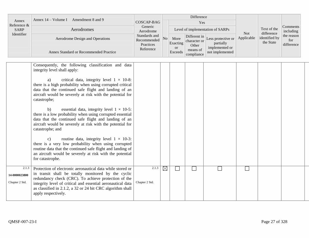
Consequently, the following classification and data
integrity level shall apply:
a) critical data, integrity level 1 × 10⁻⁸:
there is a high probability when using corrupted critical
data that the continued safe flight and landing of an
aircraft would be severely at risk with the potential for
catastrophe;
b) essential data, integrity level 1 × 10⁻⁵:
there is a low probability when using corrupted essential
data that the continued safe flight and landing of an
aircraft would be severely at risk with the potential for
catastrophe; and
c) routine data, integrity level 1 × 10⁻³:
there is a very low probability when using corrupted
routine data that the continued safe flight and landing of
an aircraft would be severely at risk with the potential
for catastrophe.
2.1.3
14-0000023800
Chapter 2 Std.
Protection of electronic aeronautical data while stored or
in transit shall be totally monitored by the cyclic
redundancy check (CRC). To achieve protection of the
integrity level of critical and essential aeronautical data
as classified in 2.1.2, a 32 or 24 bit CRC algorithm shall
apply respectively.
2.1.3
Chapter 2 Std.
Annex
Reference &
SARP
Identifier
Annex 14 – Volume I Amendment 8 and 9 COSCAP-BAG
Generic
Aerodrome
Standards and
Recommended
Practices
Reference
Difference
Not
Applicable
Text of the
difference
identified by
the State
Comments
including
the reason
for
difference
No
Yes
Aerodromes Level of implementation of SARPs
Aerodrome Design and Operations
Annex Standard or Recommended Practice
More
Exacting
or
Exceeds
Different in
character or
Other
means of
compliance
Less protective or
partially
implemented or
not implemented
QMSF-007-23-I Page 28 of 328
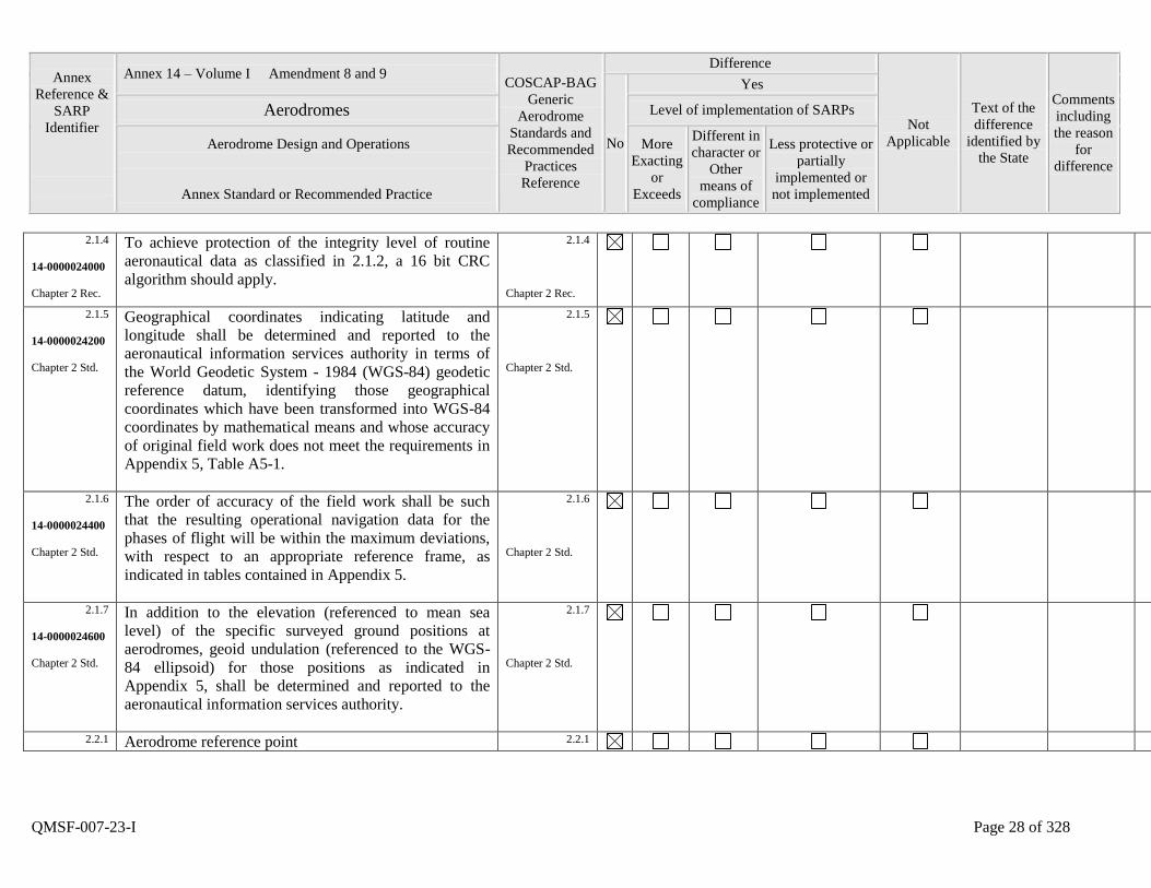
2.1.4
14-0000024000
Chapter 2 Rec.
To achieve protection of the integrity level of routine
aeronautical data as classified in 2.1.2, a 16 bit CRC
algorithm should apply.
2.1.4
Chapter 2 Rec.
2.1.5
14-0000024200
Chapter 2 Std.
Geographical coordinates indicating latitude and
longitude shall be determined and reported to the
aeronautical information services authority in terms of
the World Geodetic System - 1984 (WGS-84) geodetic
reference datum, identifying those geographical
coordinates which have been transformed into WGS-84
coordinates by mathematical means and whose accuracy
of original field work does not meet the requirements in
Appendix 5, Table A5-1.
2.1.5
Chapter 2 Std.
2.1.6
14-0000024400
Chapter 2 Std.
The order of accuracy of the field work shall be such
that the resulting operational navigation data for the
phases of flight will be within the maximum deviations,
with respect to an appropriate reference frame, as
indicated in tables contained in Appendix 5.
2.1.6
Chapter 2 Std.
2.1.7
14-0000024600
Chapter 2 Std.
In addition to the elevation (referenced to mean sea
level) of the specific surveyed ground positions at
aerodromes, geoid undulation (referenced to the WGS-
84 ellipsoid) for those positions as indicated in
Appendix 5, shall be determined and reported to the
aeronautical information services authority.
2.1.7
Chapter 2 Std.
2.2.1 Aerodrome reference point 2.2.1
Annex
Reference &
SARP
Identifier
Annex 14 – Volume I Amendment 8 and 9 COSCAP-BAG
Generic
Aerodrome
Standards and
Recommended
Practices
Reference
Difference
Not
Applicable
Text of the
difference
identified by
the State
Comments
including
the reason
for
difference
No
Yes
Aerodromes Level of implementation of SARPs
Aerodrome Design and Operations
Annex Standard or Recommended Practice
More
Exacting
or
Exceeds
Different in
character or
Other
means of
compliance
Less protective or
partially
implemented or
not implemented
QMSF-007-23-I Page 29 of 328
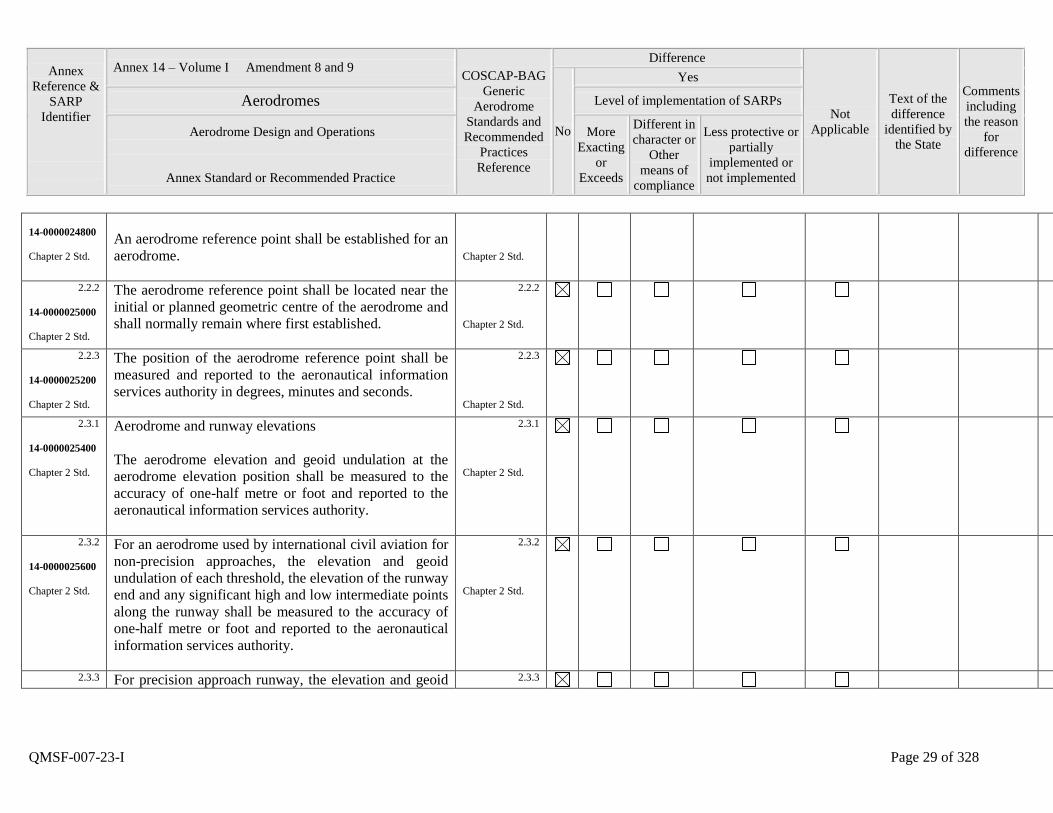
14-0000024800
Chapter 2 Std.
An aerodrome reference point shall be established for an
aerodrome.
Chapter 2 Std.
2.2.2
14-0000025000
Chapter 2 Std.
The aerodrome reference point shall be located near the
initial or planned geometric centre of the aerodrome and
shall normally remain where first established.
2.2.2
Chapter 2 Std.
2.2.3
14-0000025200
Chapter 2 Std.
The position of the aerodrome reference point shall be
measured and reported to the aeronautical information
services authority in degrees, minutes and seconds.
2.2.3
Chapter 2 Std.
2.3.1
14-0000025400
Chapter 2 Std.
Aerodrome and runway elevations
The aerodrome elevation and geoid undulation at the
aerodrome elevation position shall be measured to the
accuracy of one-half metre or foot and reported to the
aeronautical information services authority.
2.3.1
Chapter 2 Std.
2.3.2
14-0000025600
Chapter 2 Std.
For an aerodrome used by international civil aviation for
non-precision approaches, the elevation and geoid
undulation of each threshold, the elevation of the runway
end and any significant high and low intermediate points
along the runway shall be measured to the accuracy of
one-half metre or foot and reported to the aeronautical
information services authority.
2.3.2
Chapter 2 Std.
2.3.3 For precision approach runway, the elevation and geoid 2.3.3

Annex
Reference &
SARP
Identifier
Annex 14 – Volume I Amendment 8 and 9 COSCAP-BAG
Generic
Aerodrome
Standards and
Recommended
Practices
Reference
Difference
Not
Applicable
Text of the
difference
identified by
the State
Comments
including
the reason
for
difference
No
Yes
Aerodromes Level of implementation of SARPs
Aerodrome Design and Operations
Annex Standard or Recommended Practice
More
Exacting
or
Exceeds
Different in
character or
Other
means of
compliance
Less protective or
partially
implemented or
not implemented
QMSF-007-23-I Page 30 of 328
14-0000025800
Chapter 2 Std.
undulation of the threshold, the elevation of the runway
end and the highest elevation of the touchdown zone
shall be measured to the accuracy of one-quarter metre
or foot and reported to the aeronautical information
services authority.
Chapter 2 Std.
2.4.1
14-0000026000
Chapter 2 Std.
Aerodrome reference temperature
An aerodrome reference temperature shall be determined
for an aerodrome in degrees Celsius.
2.4.1
Chapter 2 Std.
2.4.2
14-0000026200
Chapter 2 Rec.
The aerodrome reference temperature should be the
monthly mean of the daily maximum temperatures for
the hottest month of the year (the hottest month being
that which has the highest monthly mean temperature).
This temperature should be averaged over a period of
years.
2.4.2
Chapter 2 Rec.
2.5.1
14-0000026400
Chapter 2 Std.
Aerodrome dimensions and related information
The following data shall be measured or described, as
appropriate, for each facility provided on an aerodrome:
a) runway - true bearing to one-hundredth of a
degree, designation number, length, width, displaced
threshold location to the nearest metre or foot, slope,
surface type, type of runway and, for a precision
approach runway category I, the existence of an obstacle
2.5.1
Chapter 2 Std.

Annex
Reference &
SARP
Identifier
Annex 14 – Volume I Amendment 8 and 9 COSCAP-BAG
Generic
Aerodrome
Standards and
Recommended
Practices
Reference
Difference
Not
Applicable
Text of the
difference
identified by
the State
Comments
including
the reason
for
difference
No
Yes
Aerodromes Level of implementation of SARPs
Aerodrome Design and Operations
Annex Standard or Recommended Practice
More
Exacting
or
Exceeds
Different in
character or
Other
means of
compliance
Less protective or
partially
implemented or
not implemented
QMSF-007-23-I Page 31 of 328
free zone when provided;
b) strip - length, width to the nearest metre or
foot, surface type;
runway end safety area - length, width to the
nearest metre or foot, surface type;
stopway - length, width to the nearest metre or
foot, surface type;
c) taxiway - designation, width, surface type;
d) apron - surface type, aircraft stands;
e) the boundaries of the air traffic control service;
f) clearway - length to the nearest metre or foot,
ground profile;
g) visual aids for approach procedures, marking
and lighting of runways, taxiways and aprons, other
visual guidance and control aids on taxiways and aprons,
including taxi-holding positions and stopbars, and
location and type of visual docking guidance systems;
h) location and radio frequency of any VOR
aerodrome check-point;
Annex
Reference &
SARP
Identifier
Annex 14 – Volume I Amendment 8 and 9 COSCAP-BAG
Generic
Aerodrome
Standards and
Recommended
Practices
Reference
Difference
Not
Applicable
Text of the
difference
identified by
the State
Comments
including
the reason
for
difference
No
Yes
Aerodromes Level of implementation of SARPs
Aerodrome Design and Operations
Annex Standard or Recommended Practice
More
Exacting
or
Exceeds
Different in
character or
Other
means of
compliance
Less protective or
partially
implemented or
not implemented
QMSF-007-23-I Page 32 of 328
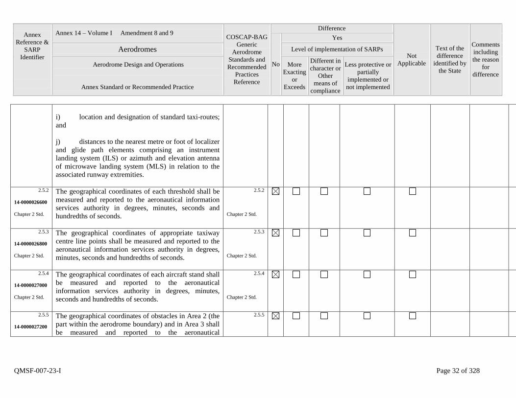
i) location and designation of standard taxi-routes;
and
j) distances to the nearest metre or foot of localizer
and glide path elements comprising an instrument
landing system (ILS) or azimuth and elevation antenna
of microwave landing system (MLS) in relation to the
associated runway extremities.
2.5.2
14-0000026600
Chapter 2 Std.
The geographical coordinates of each threshold shall be
measured and reported to the aeronautical information
services authority in degrees, minutes, seconds and
hundredths of seconds.
2.5.2
Chapter 2 Std.
2.5.3
14-0000026800
Chapter 2 Std.
The geographical coordinates of appropriate taxiway
centre line points shall be measured and reported to the
aeronautical information services authority in degrees,
minutes, seconds and hundredths of seconds.
2.5.3
Chapter 2 Std.
2.5.4
14-0000027000
Chapter 2 Std.
The geographical coordinates of each aircraft stand shall
be measured and reported to the aeronautical
information services authority in degrees, minutes,
seconds and hundredths of seconds.
2.5.4
Chapter 2 Std.
2.5.5
14-0000027200
The geographical coordinates of obstacles in Area 2 (the
part within the aerodrome boundary) and in Area 3 shall
be measured and reported to the aeronautical
2.5.5

Annex
Reference &
SARP
Identifier
Annex 14 – Volume I Amendment 8 and 9 COSCAP-BAG
Generic
Aerodrome
Standards and
Recommended
Practices
Reference
Difference
Not
Applicable
Text of the
difference
identified by
the State
Comments
including
the reason
for
difference
No
Yes
Aerodromes Level of implementation of SARPs
Aerodrome Design and Operations
Annex Standard or Recommended Practice
More
Exacting
or
Exceeds
Different in
character or
Other
means of
compliance
Less protective or
partially
implemented or
not implemented
QMSF-007-23-I Page 33 of 328
Chapter 2 Std. information services authority in degrees, minutes,
seconds and tenths of seconds. In addition, the top
elevation, type, marking and lighting (if any) of
obstacles shall be reported to the aeronautical
information services authority.
Chapter 2 Std.
2.6.1
14-0000027400
Chapter 2 Std.
Strength of pavements
The bearing strength of a pavement shall be determined.
2.6.1
Chapter 2 Std.
2.6.2
14-0000027600
Chapter 2 Std.
The bearing strength of a pavement intended for aircraft
of apron (ramp) mass greater than 5 700 kg shall be
made available using the aircraft classification number -
pavement classification number (ACN-PCN) method by
reporting all of the following information:
a) the pavement classification number
(PCN);
b) pavement type for ACN-PCN
determination;
c) subgrade strength category;
d) maximum allowable tire pressure
category or maximum allowable tire pressure value; and
e) evaluation method.
2.6.2
Chapter 2 Std.
Annex
Reference &
SARP
Identifier
Annex 14 – Volume I Amendment 8 and 9 COSCAP-BAG
Generic
Aerodrome
Standards and
Recommended
Practices
Reference
Difference
Not
Applicable
Text of the
difference
identified by
the State
Comments
including
the reason
for
difference
No
Yes
Aerodromes Level of implementation of SARPs
Aerodrome Design and Operations
Annex Standard or Recommended Practice
More
Exacting
or
Exceeds
Different in
character or
Other
means of
compliance
Less protective or
partially
implemented or
not implemented
QMSF-007-23-I Page 34 of 328
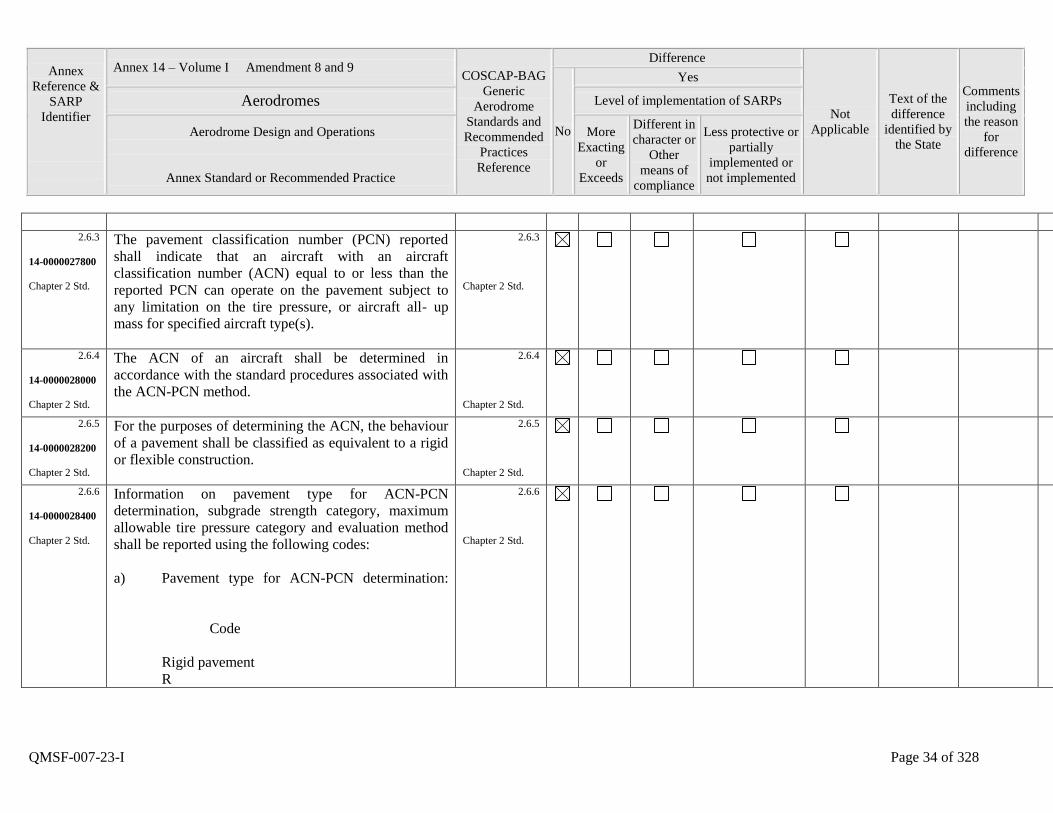
2.6.3
14-0000027800
Chapter 2 Std.
The pavement classification number (PCN) reported
shall indicate that an aircraft with an aircraft
classification number (ACN) equal to or less than the
reported PCN can operate on the pavement subject to
any limitation on the tire pressure, or aircraft all- up
mass for specified aircraft type(s).
2.6.3
Chapter 2 Std.
2.6.4
14-0000028000
Chapter 2 Std.
The ACN of an aircraft shall be determined in
accordance with the standard procedures associated with
the ACN-PCN method.
2.6.4
Chapter 2 Std.
2.6.5
14-0000028200
Chapter 2 Std.
For the purposes of determining the ACN, the behaviour
of a pavement shall be classified as equivalent to a rigid
or flexible construction.
2.6.5
Chapter 2 Std.
2.6.6
14-0000028400
Chapter 2 Std.
Information on pavement type for ACN-PCN
determination, subgrade strength category, maximum
allowable tire pressure category and evaluation method
shall be reported using the following codes:
a) Pavement type for ACN-PCN determination:
Code
Rigid pavement
R
2.6.6
Chapter 2 Std.
Annex
Reference &
SARP
Identifier
Annex 14 – Volume I Amendment 8 and 9 COSCAP-BAG
Generic
Aerodrome
Standards and
Recommended
Practices
Reference
Difference
Not
Applicable
Text of the
difference
identified by
the State
Comments
including
the reason
for
difference
No
Yes
Aerodromes Level of implementation of SARPs
Aerodrome Design and Operations
Annex Standard or Recommended Practice
More
Exacting
or
Exceeds
Different in
character or
Other
means of
compliance
Less protective or
partially
implemented or
not implemented
QMSF-007-23-I Page 35 of 328
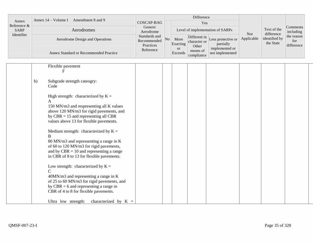
Flexible pavement
F
b) Subgrade strength cateogry:
Code
High strength: characterized by K =
A
150 MN/m3 and respresenting all K values
above 120 MN/m3 for rigid pavements, and
by CBR = 15 and representing all CBR
values above 13 for flexible pavements.
Medium strength: characterized by K =
B
80 MN/m3 and repressenting a range in K
of 60 to 120 MN/m3 for rigid pavements,
and by CBR = 10 and representing a range
in CBR of 8 to 13 for flexible pavements.
Low strength: characterized by K =
C
40MN/m3 and representing a range in K
of 25 to 60 MN/m3 for rigid pavements, and
by CBR = 6 and representing a range in
CBR of 4 to 8 for flexible pavements.
Ultra low strength: characterized by K =
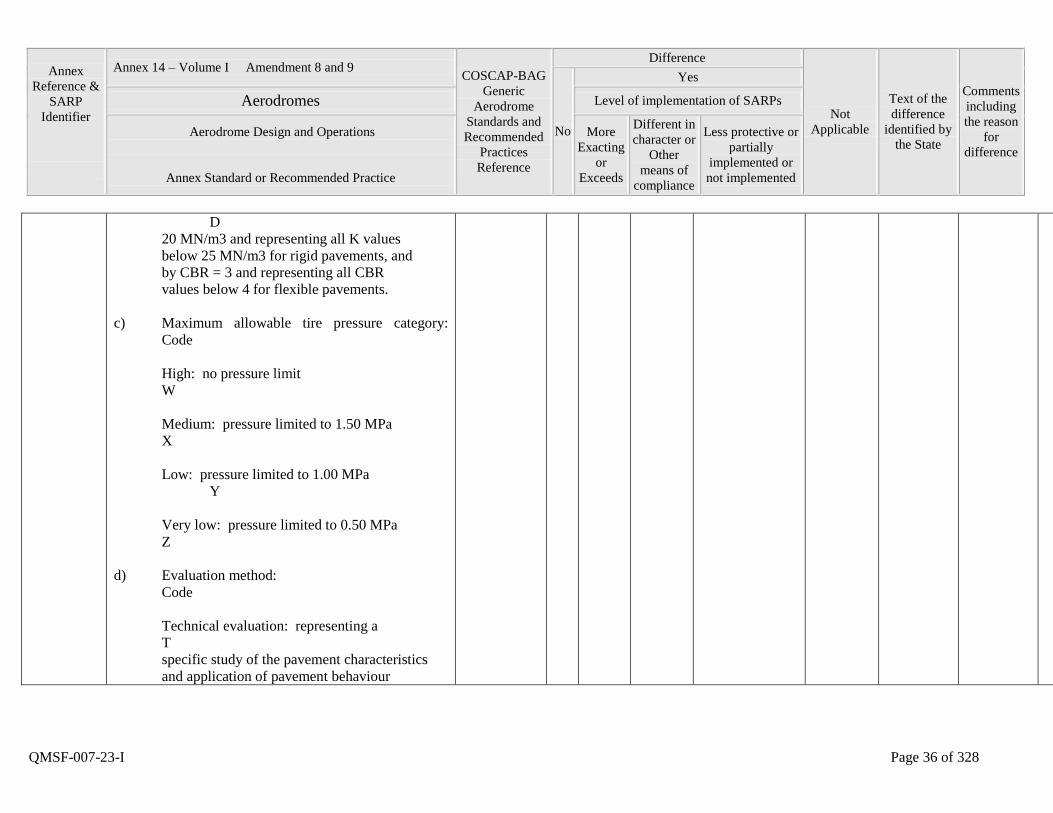
Annex
Reference &
SARP
Identifier
Annex 14 – Volume I Amendment 8 and 9 COSCAP-BAG
Generic
Aerodrome
Standards and
Recommended
Practices
Reference
Difference
Not
Applicable
Text of the
difference
identified by
the State
Comments
including
the reason
for
difference
No
Yes
Aerodromes Level of implementation of SARPs
Aerodrome Design and Operations
Annex Standard or Recommended Practice
More
Exacting
or
Exceeds
Different in
character or
Other
means of
compliance
Less protective or
partially
implemented or
not implemented
QMSF-007-23-I Page 36 of 328
D
20 MN/m3 and representing all K values
below 25 MN/m3 for rigid pavements, and
by CBR = 3 and representing all CBR
values below 4 for flexible pavements.
c) Maximum allowable tire pressure category:
Code
High: no pressure limit
W
Medium: pressure limited to 1.50 MPa
X
Low: pressure limited to 1.00 MPa
Y
Very low: pressure limited to 0.50 MPa
Z
d) Evaluation method:
Code
Technical evaluation: representing a
T
specific study of the pavement characteristics
and application of pavement behaviour
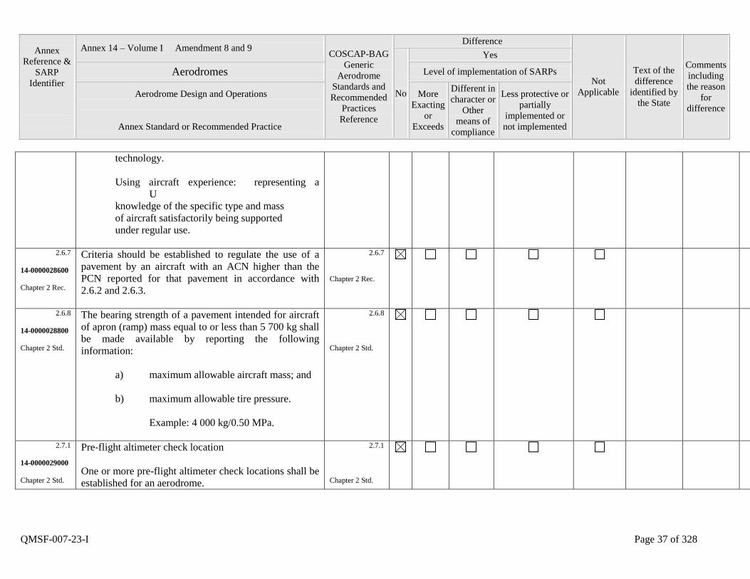
Annex
Reference &
SARP
Identifier
Annex 14 – Volume I Amendment 8 and 9 COSCAP-BAG
Generic
Aerodrome
Standards and
Recommended
Practices
Reference
Difference
Not
Applicable
Text of the
difference
identified by
the State
Comments
including
the reason
for
difference
No
Yes
Aerodromes Level of implementation of SARPs
Aerodrome Design and Operations
Annex Standard or Recommended Practice
More
Exacting
or
Exceeds
Different in
character or
Other
means of
compliance
Less protective or
partially
implemented or
not implemented
QMSF-007-23-I Page 37 of 328
technology.
Using aircraft experience: representing a
U
knowledge of the specific type and mass
of aircraft satisfactorily being supported
under regular use.
2.6.7
14-0000028600
Chapter 2 Rec.
Criteria should be established to regulate the use of a
pavement by an aircraft with an ACN higher than the
PCN reported for that pavement in accordance with
2.6.2 and 2.6.3.
2.6.7
Chapter 2 Rec.
2.6.8
14-0000028800
Chapter 2 Std.
The bearing strength of a pavement intended for aircraft
of apron (ramp) mass equal to or less than 5 700 kg shall
be made available by reporting the following
information:
a) maximum allowable aircraft mass; and
b) maximum allowable tire pressure.
Example: 4 000 kg/0.50 MPa.
2.6.8
Chapter 2 Std.
2.7.1
14-0000029000
Chapter 2 Std.
Pre-flight altimeter check location
One or more pre-flight altimeter check locations shall be
established for an aerodrome.
2.7.1
Chapter 2 Std.
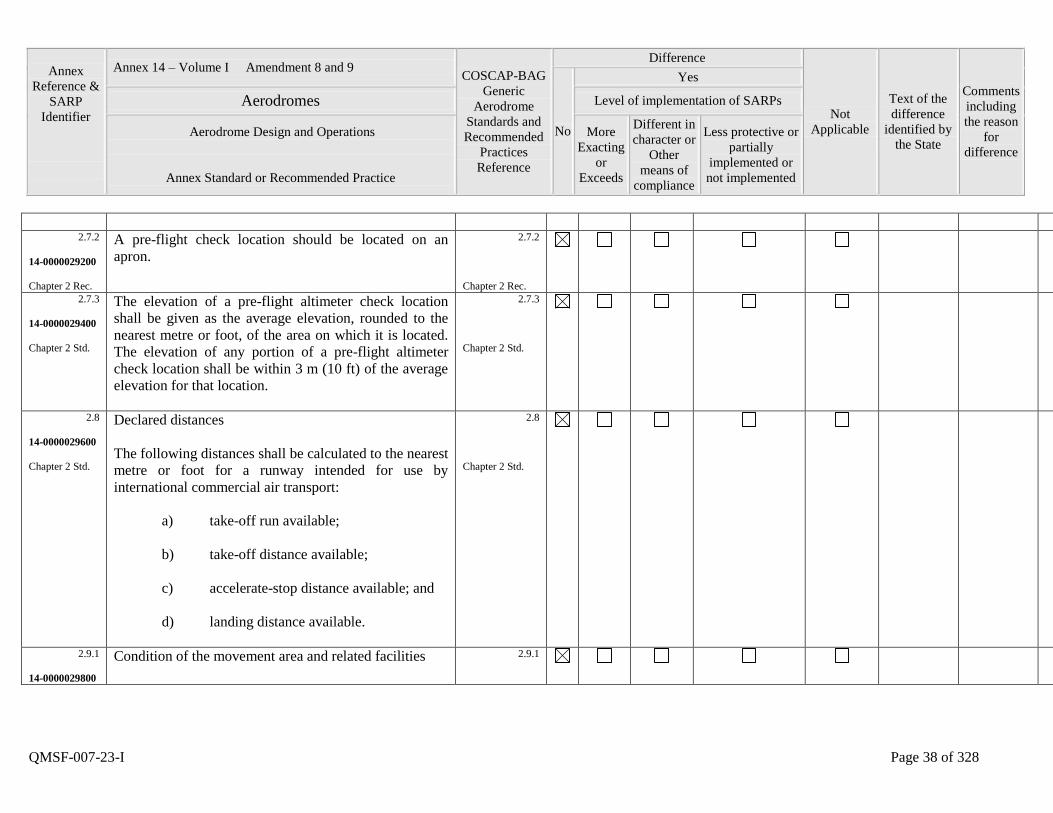
Annex
Reference &
SARP
Identifier
Annex 14 – Volume I Amendment 8 and 9 COSCAP-BAG
Generic
Aerodrome
Standards and
Recommended
Practices
Reference
Difference
Not
Applicable
Text of the
difference
identified by
the State
Comments
including
the reason
for
difference
No
Yes
Aerodromes Level of implementation of SARPs
Aerodrome Design and Operations
Annex Standard or Recommended Practice
More
Exacting
or
Exceeds
Different in
character or
Other
means of
compliance
Less protective or
partially
implemented or
not implemented
QMSF-007-23-I Page 38 of 328
2.7.2
14-0000029200
Chapter 2 Rec.
A pre-flight check location should be located on an
apron.
2.7.2
Chapter 2 Rec.
2.7.3
14-0000029400
Chapter 2 Std.
The elevation of a pre-flight altimeter check location
shall be given as the average elevation, rounded to the
nearest metre or foot, of the area on which it is located.
The elevation of any portion of a pre-flight altimeter
check location shall be within 3 m (10 ft) of the average
elevation for that location.
2.7.3
Chapter 2 Std.
2.8
14-0000029600
Chapter 2 Std.
Declared distances
The following distances shall be calculated to the nearest
metre or foot for a runway intended for use by
international commercial air transport:
a) take-off run available;
b) take-off distance available;
c) accelerate-stop distance available; and
d) landing distance available.
2.8
Chapter 2 Std.
2.9.1
14-0000029800
Condition of the movement area and related facilities
2.9.1
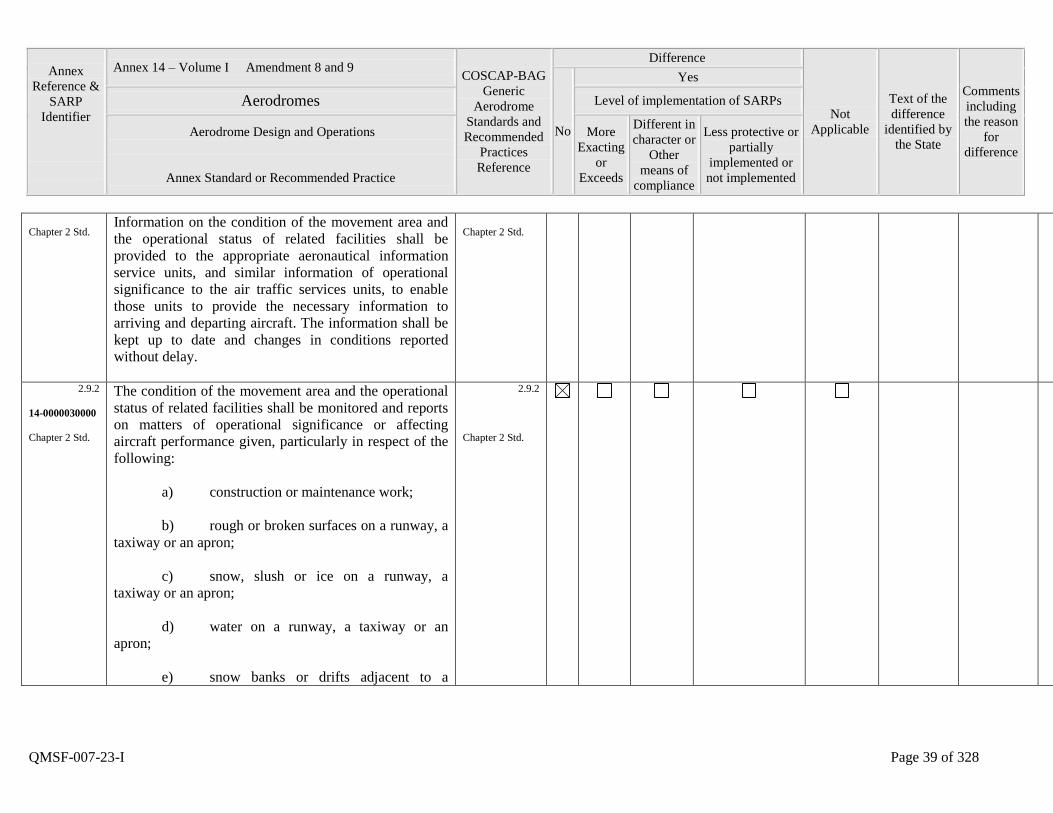
Annex
Reference &
SARP
Identifier
Annex 14 – Volume I Amendment 8 and 9 COSCAP-BAG
Generic
Aerodrome
Standards and
Recommended
Practices
Reference
Difference
Not
Applicable
Text of the
difference
identified by
the State
Comments
including
the reason
for
difference
No
Yes
Aerodromes Level of implementation of SARPs
Aerodrome Design and Operations
Annex Standard or Recommended Practice
More
Exacting
or
Exceeds
Different in
character or
Other
means of
compliance
Less protective or
partially
implemented or
not implemented
QMSF-007-23-I Page 39 of 328
Chapter 2 Std. Information on the condition of the movement area and
the operational status of related facilities shall be
provided to the appropriate aeronautical information
service units, and similar information of operational
significance to the air traffic services units, to enable
those units to provide the necessary information to
arriving and departing aircraft. The information shall be
kept up to date and changes in conditions reported
without delay.
Chapter 2 Std.
2.9.2
14-0000030000
Chapter 2 Std.
The condition of the movement area and the operational
status of related facilities shall be monitored and reports
on matters of operational significance or affecting
aircraft performance given, particularly in respect of the
following:
a) construction or maintenance work;
b) rough or broken surfaces on a runway, a
taxiway or an apron;
c) snow, slush or ice on a runway, a
taxiway or an apron;
d) water on a runway, a taxiway or an
apron;
e) snow banks or drifts adjacent to a
2.9.2
Chapter 2 Std.

Annex
Reference &
SARP
Identifier
Annex 14 – Volume I Amendment 8 and 9 COSCAP-BAG
Generic
Aerodrome
Standards and
Recommended
Practices
Reference
Difference
Not
Applicable
Text of the
difference
identified by
the State
Comments
including
the reason
for
difference
No
Yes
Aerodromes Level of implementation of SARPs
Aerodrome Design and Operations
Annex Standard or Recommended Practice
More
Exacting
or
Exceeds
Different in
character or
Other
means of
compliance
Less protective or
partially
implemented or
not implemented
QMSF-007-23-I Page 40 of 328
runway, a taxiway or an apron;
f) anti-icing or de-icing liquid chemicals
on a runway or a taxiway;
g) other temporary hazards, including
parked aircraft;
h) failure or irregular operation of part or
all of the aerodrome visual aids; and
i) failure of the normal or secondary
power supply.
2.9.3
14-0000030200
Chapter 2 Rec.
To facilitate compliance with 2.9.1 and 2.9.2 inspections
of the movement area should be carried out each day at
least once where the code number is 1 or 2 and at least
twice where the code number is 3 or 4.
2.9.3
Chapter 2 Std
2.9.4
14-0000030400
Chapter 2 Rec.
Water on a runway
Whenever water is present on a runway, a description of
the runway surface conditions on the centre half of the
width of the runway, including the possible assessment
of water depth, where applicable, should be made
available using the following terms:
DAMP - the surface shows a change of colour
2.9.4
Chapter 2 Std.
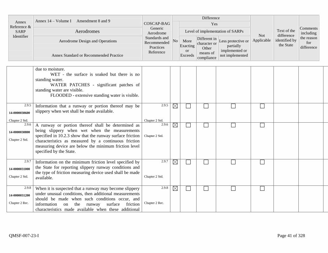
Annex
Reference &
SARP
Identifier
Annex 14 – Volume I Amendment 8 and 9 COSCAP-BAG
Generic
Aerodrome
Standards and
Recommended
Practices
Reference
Difference
Not
Applicable
Text of the
difference
identified by
the State
Comments
including
the reason
for
difference
No
Yes
Aerodromes Level of implementation of SARPs
Aerodrome Design and Operations
Annex Standard or Recommended Practice
More
Exacting
or
Exceeds
Different in
character or
Other
means of
compliance
Less protective or
partially
implemented or
not implemented
QMSF-007-23-I Page 41 of 328
due to moisture.
WET - the surface is soaked but there is no
standing water.
WATER PATCHES - significant patches of
standing water are visible.
FLOODED - extensive standing water is visible.
2.9.5
14-0000030600
Chapter 2 Std.
Information that a runway or portion thereof may be
slippery when wet shall be made available.
2.9.5
Chapter 2 Std.
2.9.6
14-0000030800
Chapter 2 Std.
A runway or portion thereof shall be determined as
being slippery when wet when the measurements
specified in 10.2.3 show that the runway surface friction
characteristics as measured by a continuous friction
measuring device are below the minimum friction level
specified by the State.
2.9.6
Chapter 2 Std.
2.9.7
14-0000031000
Chapter 2 Std.
Information on the minimum friction level specified by
the State for reporting slippery runway conditions and
the type of friction measuring device used shall be made
available.
2.9.7
Chapter 2 Std.
2.9.8
14-0000031200
Chapter 2 Rec.
When it is suspected that a runway may become slippery
under unusual conditions, then additional measurements
should be made when such conditions occur, and
information on the runway surface friction
characteristics made available when these additional
2.9.8
Chapter 2 Rec.
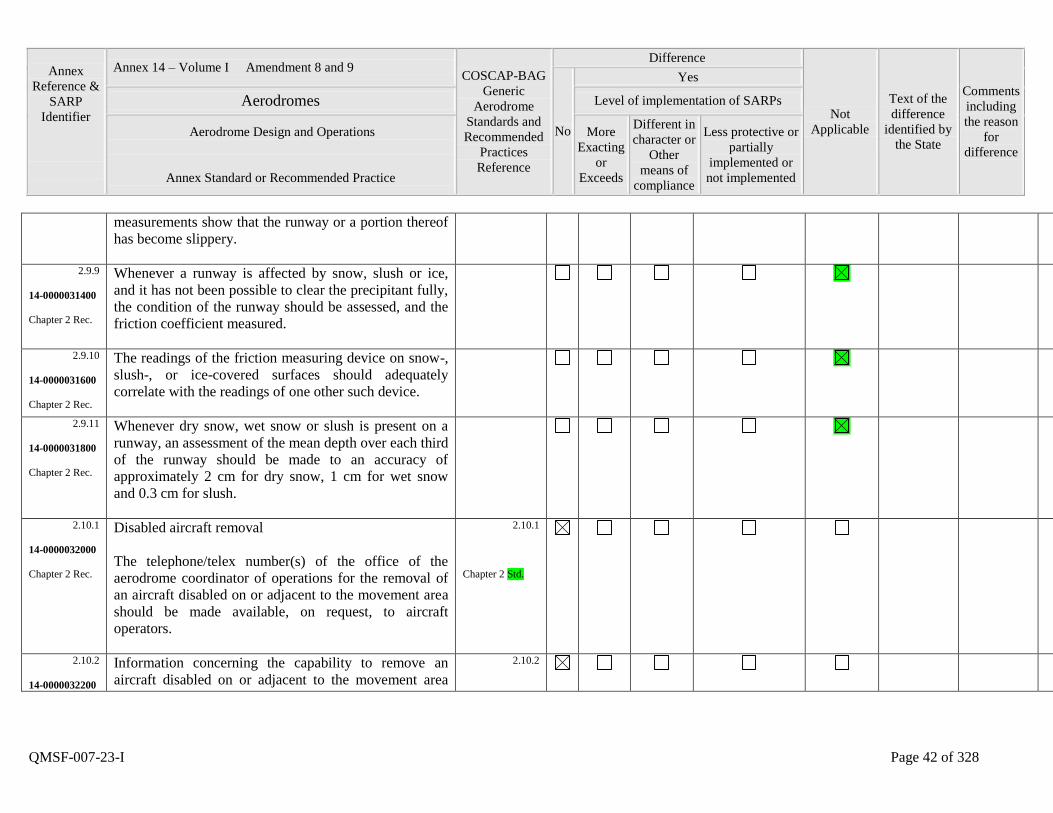
Annex
Reference &
SARP
Identifier
Annex 14 – Volume I Amendment 8 and 9 COSCAP-BAG
Generic
Aerodrome
Standards and
Recommended
Practices
Reference
Difference
Not
Applicable
Text of the
difference
identified by
the State
Comments
including
the reason
for
difference
No
Yes
Aerodromes Level of implementation of SARPs
Aerodrome Design and Operations
Annex Standard or Recommended Practice
More
Exacting
or
Exceeds
Different in
character or
Other
means of
compliance
Less protective or
partially
implemented or
not implemented
QMSF-007-23-I Page 42 of 328
measurements show that the runway or a portion thereof
has become slippery.
2.9.9
14-0000031400
Chapter 2 Rec.
Whenever a runway is affected by snow, slush or ice,
and it has not been possible to clear the precipitant fully,
the condition of the runway should be assessed, and the
friction coefficient measured.
2.9.10
14-0000031600
Chapter 2 Rec.
The readings of the friction measuring device on snow-,
slush-, or ice-covered surfaces should adequately
correlate with the readings of one other such device.
2.9.11
14-0000031800
Chapter 2 Rec.
Whenever dry snow, wet snow or slush is present on a
runway, an assessment of the mean depth over each third
of the runway should be made to an accuracy of
approximately 2 cm for dry snow, 1 cm for wet snow
and 0.3 cm for slush.
2.10.1
14-0000032000
Chapter 2 Rec.
Disabled aircraft removal
The telephone/telex number(s) of the office of the
aerodrome coordinator of operations for the removal of
an aircraft disabled on or adjacent to the movement area
should be made available, on request, to aircraft
operators.
2.10.1
Chapter 2 Std.
2.10.2
14-0000032200
Information concerning the capability to remove an
aircraft disabled on or adjacent to the movement area
2.10.2

Annex
Reference &
SARP
Identifier
Annex 14 – Volume I Amendment 8 and 9 COSCAP-BAG
Generic
Aerodrome
Standards and
Recommended
Practices
Reference
Difference
Not
Applicable
Text of the
difference
identified by
the State
Comments
including
the reason
for
difference
No
Yes
Aerodromes Level of implementation of SARPs
Aerodrome Design and Operations
Annex Standard or Recommended Practice
More
Exacting
or
Exceeds
Different in
character or
Other
means of
compliance
Less protective or
partially
implemented or
not implemented
QMSF-007-23-I Page 43 of 328
Chapter 2 Rec. should be made available.
Chapter 2 Std.
2.11.1
14-0000032400
Chapter 2 Std.
Rescue and fire fighting
Information concerning the level of protection provided
at an aerodrome for aircraft rescue and fire fighting
purposes shall be made available.
2.11.1
Chapter 2 Std.
2.11.2
14-0000032600
Chapter 2 Rec.
The level of protection normally available at an
aerodrome should be expressed in terms of the category
of the rescue and fire fighting services as described in
9.2 and in accordance with the types and amounts of
extinguishing agents normally available at the
aerodrome.
2.11.2
Chapter 2 Std.
2.11.3
14-0000032800
Chapter 2 Std.
Significant changes in the level of protection normally
available at an aerodrome for rescue and fire fighting
shall be notified to the appropriate air traffic services
units and aeronautical information units to enable those
units to provide the necessary information to arriving
and departing aircraft. When such a change has been
corrected, the above units shall be advised accordingly.
2.11.3
Chapter 2 Std.
2.11.4
14-0000033000
Chapter 2 Rec.
A significant change should be expressed in terms of the
new category of the rescue and fire fighting service
available at the aerodrome.
2.11.4
Chapter 2 Std.
2.12 Visual approach slope indicator systems 2.12

Annex
Reference &
SARP
Identifier
Annex 14 – Volume I Amendment 8 and 9 COSCAP-BAG
Generic
Aerodrome
Standards and
Recommended
Practices
Reference
Difference
Not
Applicable
Text of the
difference
identified by
the State
Comments
including
the reason
for
difference
No
Yes
Aerodromes Level of implementation of SARPs
Aerodrome Design and Operations
Annex Standard or Recommended Practice
More
Exacting
or
Exceeds
Different in
character or
Other
means of
compliance
Less protective or
partially
implemented or
not implemented
QMSF-007-23-I Page 44 of 328
14-0000033200
Chapter 2 Std.
The following information concerning a visual approach
slope indicator system installation shall be made
available:
a) associated runway designation number;
b) type of system according to 5.3.5.2. For
an AT-VASIS, PAPI or APAPI installation, the side of
the runway on which the lights are installed, i.e. left or
right, shall be given;
c) where the axis of the system is not
parallel to the runway centre line, the angle of
displacement and the direction of displacement, i.e. left
or right shall be indicated;
d) nominal approach slope angle(s). For a
T-VASIS or an AT-VASIS this shall be angle q
according to the formula in Figure 5-17 and for a PAPI
and an APAPI this shall be angle (B + C) ̧2 and (A +
B) ¸ 2, respectively as in Figure 5-19; and
e) minimum eye height(s) over the
threshold of the on-slope signal(s). For a T-VASIS or an
AT-VASIS this shall be the lowest height at which only
the wing bar(s) are visible; however, the additional
heights at which the wing bar(s) plus one, two or three
Chapter 2 Std.
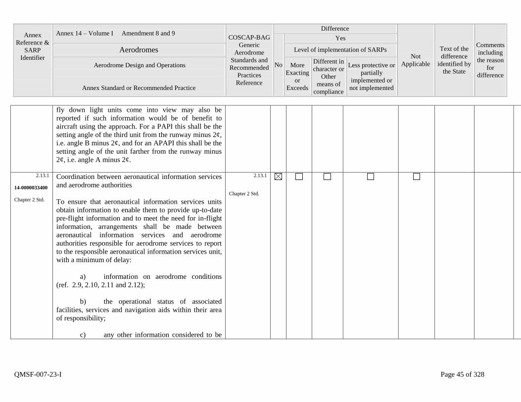
Annex
Reference &
SARP
Identifier
Annex 14 – Volume I Amendment 8 and 9 COSCAP-BAG
Generic
Aerodrome
Standards and
Recommended
Practices
Reference
Difference
Not
Applicable
Text of the
difference
identified by
the State
Comments
including
the reason
for
difference
No
Yes
Aerodromes Level of implementation of SARPs
Aerodrome Design and Operations
Annex Standard or Recommended Practice
More
Exacting
or
Exceeds
Different in
character or
Other
means of
compliance
Less protective or
partially
implemented or
not implemented
QMSF-007-23-I Page 45 of 328
fly down light units come into view may also be
reported if such information would be of benefit to
aircraft using the approach. For a PAPI this shall be the
setting angle of the third unit from the runway minus 2¢,
i.e. angle B minus 2¢, and for an APAPI this shall be the
setting angle of the unit farther from the runway minus
2¢, i.e. angle A minus 2¢.
2.13.1
14-0000033400
Chapter 2 Std.
Coordination between aeronautical information services
and aerodrome authorities
To ensure that aeronautical information services units
obtain information to enable them to provide up-to-date
pre-flight information and to meet the need for in-flight
information, arrangements shall be made between
aeronautical information services and aerodrome
authorities responsible for aerodrome services to report
to the responsible aeronautical information services unit,
with a minimum of delay:
a) information on aerodrome conditions
(ref. 2.9, 2.10, 2.11 and 2.12);
b) the operational status of associated
facilities, services and navigation aids within their area
of responsibility;
c) any other information considered to be
2.13.1
Chapter 2 Std.
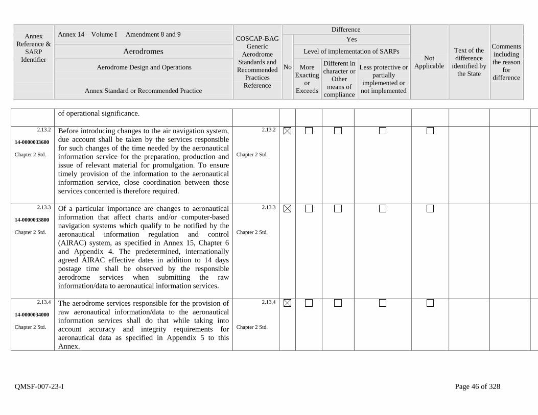
Annex
Reference &
SARP
Identifier
Annex 14 – Volume I Amendment 8 and 9 COSCAP-BAG
Generic
Aerodrome
Standards and
Recommended
Practices
Reference
Difference
Not
Applicable
Text of the
difference
identified by
the State
Comments
including
the reason
for
difference
No
Yes
Aerodromes Level of implementation of SARPs
Aerodrome Design and Operations
Annex Standard or Recommended Practice
More
Exacting
or
Exceeds
Different in
character or
Other
means of
compliance
Less protective or
partially
implemented or
not implemented
QMSF-007-23-I Page 46 of 328
of operational significance.
2.13.2
14-0000033600
Chapter 2 Std.
Before introducing changes to the air navigation system,
due account shall be taken by the services responsible
for such changes of the time needed by the aeronautical
information service for the preparation, production and
issue of relevant material for promulgation. To ensure
timely provision of the information to the aeronautical
information service, close coordination between those
services concerned is therefore required.
2.13.2
Chapter 2 Std.
2.13.3
14-0000033800
Chapter 2 Std.
Of a particular importance are changes to aeronautical
information that affect charts and/or computer-based
navigation systems which qualify to be notified by the
aeronautical information regulation and control
(AIRAC) system, as specified in Annex 15, Chapter 6
and Appendix 4. The predetermined, internationally
agreed AIRAC effective dates in addition to 14 days
postage time shall be observed by the responsible
aerodrome services when submitting the raw
information/data to aeronautical information services.
2.13.3
Chapter 2 Std.
2.13.4
14-0000034000
Chapter 2 Std.
The aerodrome services responsible for the provision of
raw aeronautical information/data to the aeronautical
information services shall do that while taking into
account accuracy and integrity requirements for
aeronautical data as specified in Appendix 5 to this
Annex.
2.13.4
Chapter 2 Std.
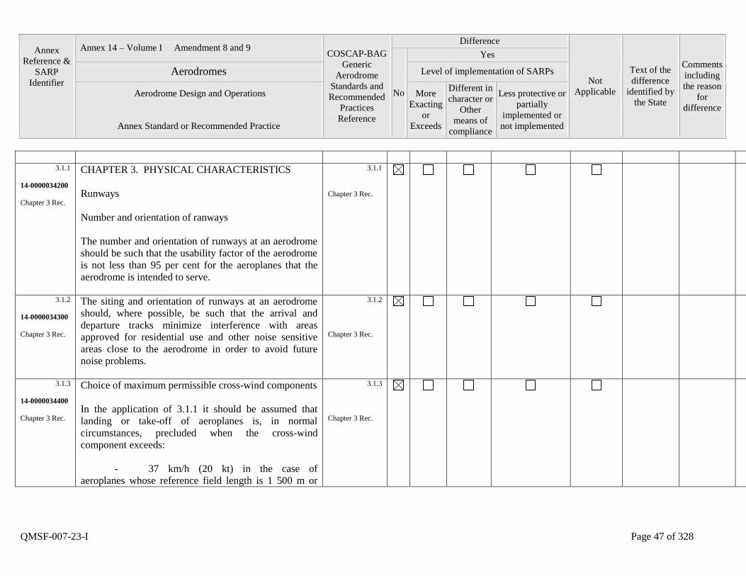
Annex
Reference &
SARP
Identifier
Annex 14 – Volume I Amendment 8 and 9 COSCAP-BAG
Generic
Aerodrome
Standards and
Recommended
Practices
Reference
Difference
Not
Applicable
Text of the
difference
identified by
the State
Comments
including
the reason
for
difference
No
Yes
Aerodromes Level of implementation of SARPs
Aerodrome Design and Operations
Annex Standard or Recommended Practice
More
Exacting
or
Exceeds
Different in
character or
Other
means of
compliance
Less protective or
partially
implemented or
not implemented
QMSF-007-23-I Page 47 of 328
3.1.1
14-0000034200
Chapter 3 Rec.
CHAPTER 3. PHYSICAL CHARACTERISTICS
Runways
Number and orientation of ranways
The number and orientation of runways at an aerodrome
should be such that the usability factor of the aerodrome
is not less than 95 per cent for the aeroplanes that the
aerodrome is intended to serve.
3.1.1
Chapter 3 Rec.
3.1.2
14-0000034300
Chapter 3 Rec.
The siting and orientation of runways at an aerodrome
should, where possible, be such that the arrival and
departure tracks minimize interference with areas
approved for residential use and other noise sensitive
areas close to the aerodrome in order to avoid future
noise problems.
3.1.2
Chapter 3 Rec.
3.1.3
14-0000034400
Chapter 3 Rec.
Choice of maximum permissible cross-wind components
In the application of 3.1.1 it should be assumed that
landing or take-off of aeroplanes is, in normal
circumstances, precluded when the cross-wind
component exceeds:
- 37 km/h (20 kt) in the case of
aeroplanes whose reference field length is 1 500 m or
3.1.3
Chapter 3 Rec.
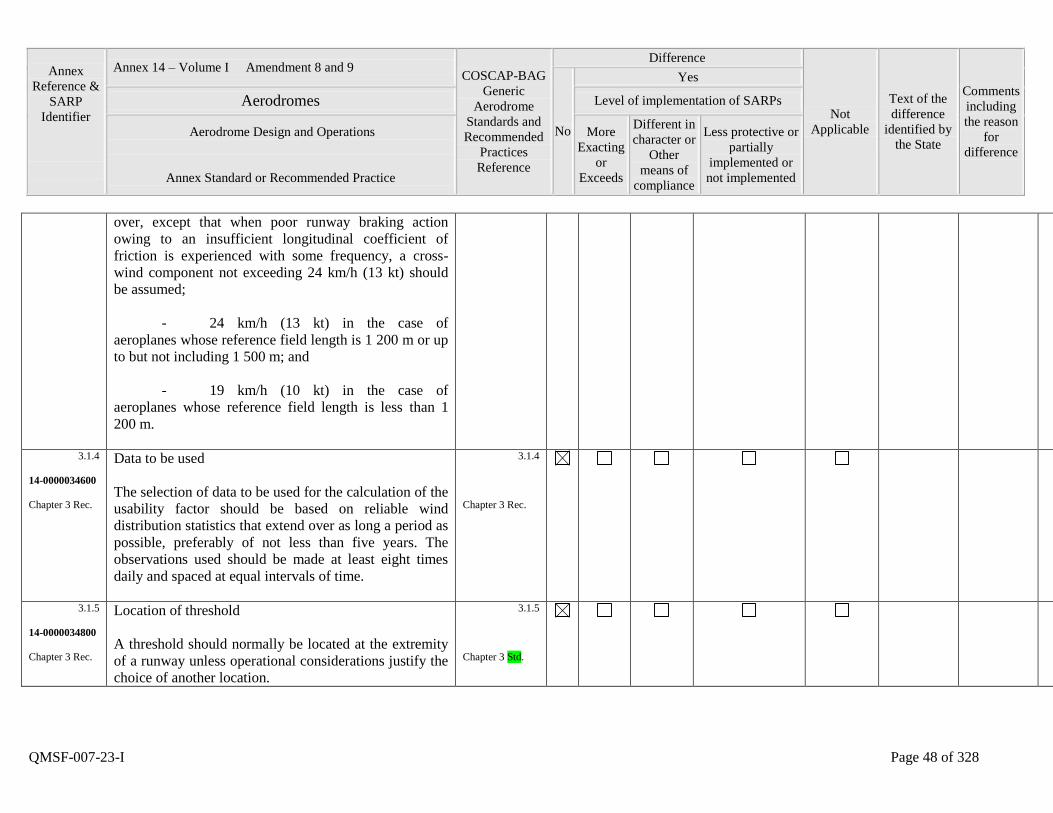
Annex
Reference &
SARP
Identifier
Annex 14 – Volume I Amendment 8 and 9 COSCAP-BAG
Generic
Aerodrome
Standards and
Recommended
Practices
Reference
Difference
Not
Applicable
Text of the
difference
identified by
the State
Comments
including
the reason
for
difference
No
Yes
Aerodromes Level of implementation of SARPs
Aerodrome Design and Operations
Annex Standard or Recommended Practice
More
Exacting
or
Exceeds
Different in
character or
Other
means of
compliance
Less protective or
partially
implemented or
not implemented
QMSF-007-23-I Page 48 of 328
over, except that when poor runway braking action
owing to an insufficient longitudinal coefficient of
friction is experienced with some frequency, a cross-
wind component not exceeding 24 km/h (13 kt) should
be assumed;
- 24 km/h (13 kt) in the case of
aeroplanes whose reference field length is 1 200 m or up
to but not including 1 500 m; and
- 19 km/h (10 kt) in the case of
aeroplanes whose reference field length is less than 1
200 m.
3.1.4
14-0000034600
Chapter 3 Rec.
Data to be used
The selection of data to be used for the calculation of the
usability factor should be based on reliable wind
distribution statistics that extend over as long a period as
possible, preferably of not less than five years. The
observations used should be made at least eight times
daily and spaced at equal intervals of time.
3.1.4
Chapter 3 Rec.
3.1.5
14-0000034800
Chapter 3 Rec.
Location of threshold
A threshold should normally be located at the extremity
of a runway unless operational considerations justify the
choice of another location.
3.1.5
Chapter 3 Std.
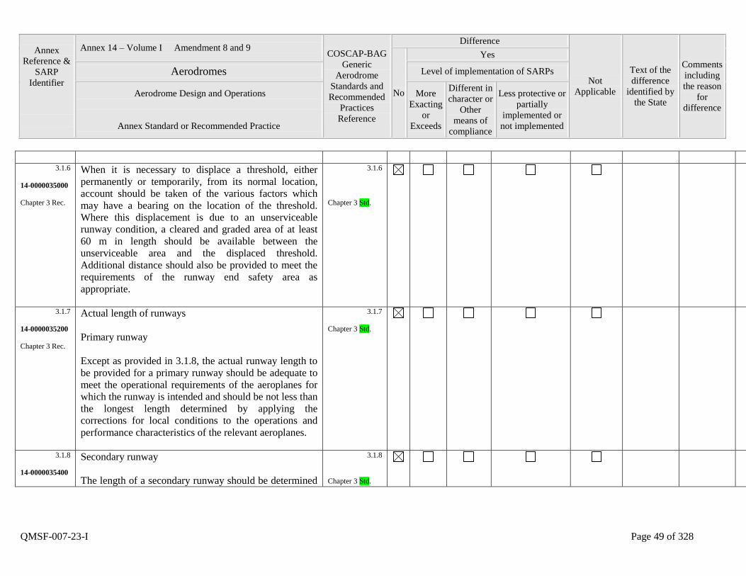
Annex
Reference &
SARP
Identifier
Annex 14 – Volume I Amendment 8 and 9 COSCAP-BAG
Generic
Aerodrome
Standards and
Recommended
Practices
Reference
Difference
Not
Applicable
Text of the
difference
identified by
the State
Comments
including
the reason
for
difference
No
Yes
Aerodromes Level of implementation of SARPs
Aerodrome Design and Operations
Annex Standard or Recommended Practice
More
Exacting
or
Exceeds
Different in
character or
Other
means of
compliance
Less protective or
partially
implemented or
not implemented
QMSF-007-23-I Page 49 of 328
3.1.6
14-0000035000
Chapter 3 Rec.
When it is necessary to displace a threshold, either
permanently or temporarily, from its normal location,
account should be taken of the various factors which
may have a bearing on the location of the threshold.
Where this displacement is due to an unserviceable
runway condition, a cleared and graded area of at least
60 m in length should be available between the
unserviceable area and the displaced threshold.
Additional distance should also be provided to meet the
requirements of the runway end safety area as
appropriate.
3.1.6
Chapter 3 Std.
3.1.7
14-0000035200
Chapter 3 Rec.
Actual length of runways
Primary runway
Except as provided in 3.1.8, the actual runway length to
be provided for a primary runway should be adequate to
meet the operational requirements of the aeroplanes for
which the runway is intended and should be not less than
the longest length determined by applying the
corrections for local conditions to the operations and
performance characteristics of the relevant aeroplanes.
3.1.7
Chapter 3 Std.
3.1.8
14-0000035400
Secondary runway
The length of a secondary runway should be determined
3.1.8
Chapter 3 Std.
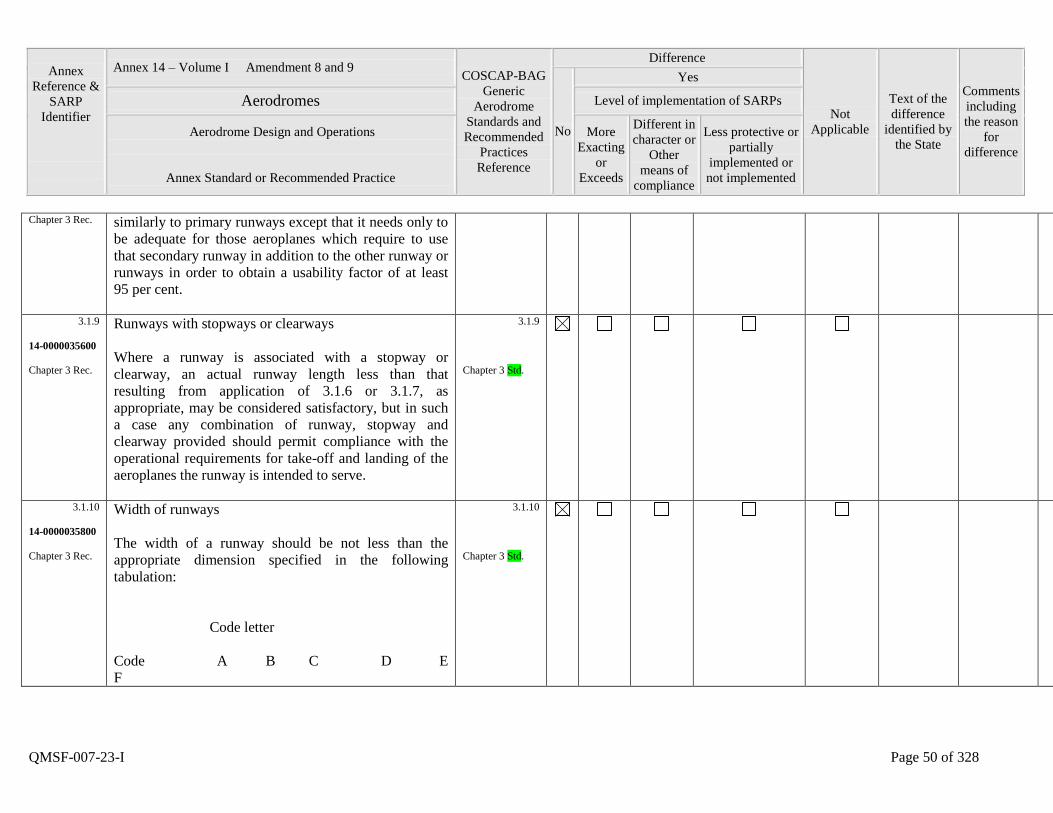
Annex
Reference &
SARP
Identifier
Annex 14 – Volume I Amendment 8 and 9 COSCAP-BAG
Generic
Aerodrome
Standards and
Recommended
Practices
Reference
Difference
Not
Applicable
Text of the
difference
identified by
the State
Comments
including
the reason
for
difference
No
Yes
Aerodromes Level of implementation of SARPs
Aerodrome Design and Operations
Annex Standard or Recommended Practice
More
Exacting
or
Exceeds
Different in
character or
Other
means of
compliance
Less protective or
partially
implemented or
not implemented
QMSF-007-23-I Page 50 of 328
Chapter 3 Rec. similarly to primary runways except that it needs only to
be adequate for those aeroplanes which require to use
that secondary runway in addition to the other runway or
runways in order to obtain a usability factor of at least
95 per cent.
3.1.9
14-0000035600
Chapter 3 Rec.
Runways with stopways or clearways
Where a runway is associated with a stopway or
clearway, an actual runway length less than that
resulting from application of 3.1.6 or 3.1.7, as
appropriate, may be considered satisfactory, but in such
a case any combination of runway, stopway and
clearway provided should permit compliance with the
operational requirements for take-off and landing of the
aeroplanes the runway is intended to serve.
3.1.9
Chapter 3 Std.
3.1.10
14-0000035800
Chapter 3 Rec.
Width of runways
The width of a runway should be not less than the
appropriate dimension specified in the following
tabulation:
Code letter
Code A B C D E
F
3.1.10
Chapter 3 Std.
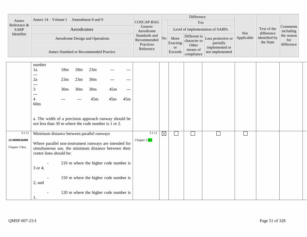
Annex
Reference &
SARP
Identifier
Annex 14 – Volume I Amendment 8 and 9 COSCAP-BAG
Generic
Aerodrome
Standards and
Recommended
Practices
Reference
Difference
Not
Applicable
Text of the
difference
identified by
the State
Comments
including
the reason
for
difference
No
Yes
Aerodromes Level of implementation of SARPs
Aerodrome Design and Operations
Annex Standard or Recommended Practice
More
Exacting
or
Exceeds
Different in
character or
Other
means of
compliance
Less protective or
partially
implemented or
not implemented
QMSF-007-23-I Page 51 of 328
number
1a 18m 18m 23m --- ---
---
2a 23m 23m 30m --- ---
---
3 30m 30m 30m 45m ---
---
4 --- --- 45m 45m 45m
60m
a. The width of a precision approach runway should be
not less than 30 m where the code number is 1 or 2.
3.1.11
14-0000036000
Chapter 3 Rec.
Minimum distance between parallel runways
Where parallel non-instrument runways are intended for
simultaneous use, the minimum distance between their
centre lines should be:
- 210 m where the higher code number is
3 or 4;
- 150 m where the higher code number is
2; and
- 120 m where the higher code number is
1.
3.1.11
Chapter 3 Std.
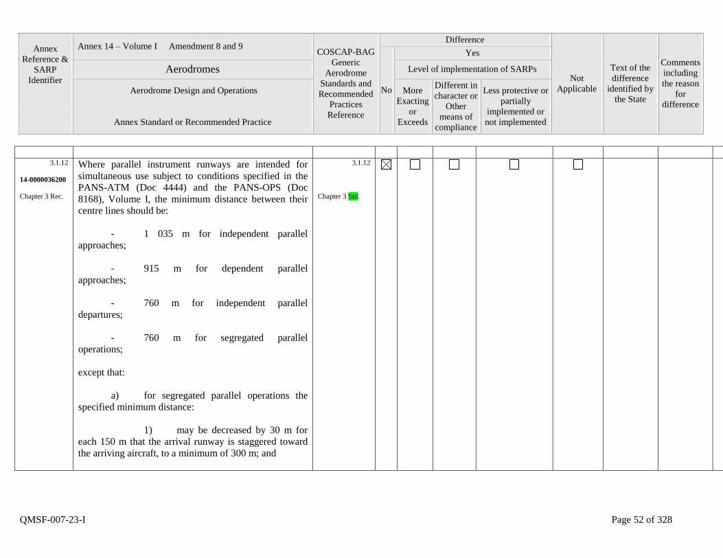
Annex
Reference &
SARP
Identifier
Annex 14 – Volume I Amendment 8 and 9 COSCAP-BAG
Generic
Aerodrome
Standards and
Recommended
Practices
Reference
Difference
Not
Applicable
Text of the
difference
identified by
the State
Comments
including
the reason
for
difference
No
Yes
Aerodromes Level of implementation of SARPs
Aerodrome Design and Operations
Annex Standard or Recommended Practice
More
Exacting
or
Exceeds
Different in
character or
Other
means of
compliance
Less protective or
partially
implemented or
not implemented
QMSF-007-23-I Page 52 of 328
3.1.12
14-0000036200
Chapter 3 Rec.
Where parallel instrument runways are intended for
simultaneous use subject to conditions specified in the
PANS-ATM (Doc 4444) and the PANS-OPS (Doc
8168), Volume I, the minimum distance between their
centre lines should be:
- 1 035 m for independent parallel
approaches;
- 915 m for dependent parallel
approaches;
- 760 m for independent parallel
departures;
- 760 m for segregated parallel
operations;
except that:
a) for segregated parallel operations the
specified minimum distance:
1) may be decreased by 30 m for
each 150 m that the arrival runway is staggered toward
the arriving aircraft, to a minimum of 300 m; and
3.1.12
Chapter 3 Std.
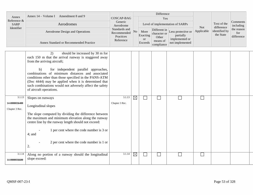
Annex
Reference &
SARP
Identifier
Annex 14 – Volume I Amendment 8 and 9 COSCAP-BAG
Generic
Aerodrome
Standards and
Recommended
Practices
Reference
Difference
Not
Applicable
Text of the
difference
identified by
the State
Comments
including
the reason
for
difference
No
Yes
Aerodromes Level of implementation of SARPs
Aerodrome Design and Operations
Annex Standard or Recommended Practice
More
Exacting
or
Exceeds
Different in
character or
Other
means of
compliance
Less protective or
partially
implemented or
not implemented
QMSF-007-23-I Page 53 of 328
2) should be increased by 30 m for
each 150 m that the arrival runway is staggered away
from the arriving aircraft;
b) for independent parallel approaches,
combinations of minimum distances and associated
conditions other than those specified in the PANS-ATM
(Doc 4444) may be applied when it is determined that
such combinations would not adversely affect the safety
of aircraft operations.
3.1.13
14-0000036400
Chapter 3 Rec.
Slopes on runways
Longitudinal slopes
The slope computed by dividing the difference between
the maximum and minimum elevation along the runway
centre line by the runway length should not exceed:
- 1 per cent where the code number is 3 or
4; and
- 2 per cent where the code number is 1 or
2.
3.1.13
Chapter 3 Rec.
3.1.14
14-0000036600
Along no portion of a runway should the longitudinal
slope exceed:
3.1.14
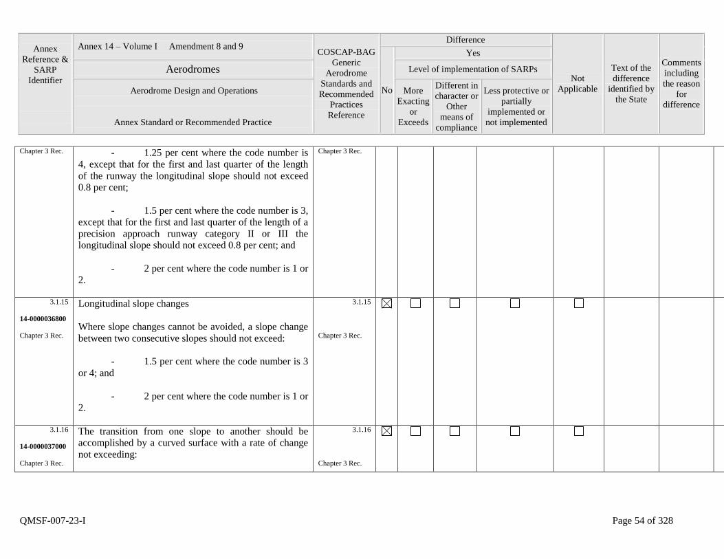
Annex
Reference &
SARP
Identifier
Annex 14 – Volume I Amendment 8 and 9 COSCAP-BAG
Generic
Aerodrome
Standards and
Recommended
Practices
Reference
Difference
Not
Applicable
Text of the
difference
identified by
the State
Comments
including
the reason
for
difference
No
Yes
Aerodromes Level of implementation of SARPs
Aerodrome Design and Operations
Annex Standard or Recommended Practice
More
Exacting
or
Exceeds
Different in
character or
Other
means of
compliance
Less protective or
partially
implemented or
not implemented
QMSF-007-23-I Page 54 of 328
Chapter 3 Rec. - 1.25 per cent where the code number is
4, except that for the first and last quarter of the length
of the runway the longitudinal slope should not exceed
0.8 per cent;
- 1.5 per cent where the code number is 3,
except that for the first and last quarter of the length of a
precision approach runway category II or III the
longitudinal slope should not exceed 0.8 per cent; and
- 2 per cent where the code number is 1 or
2.
Chapter 3 Rec.
3.1.15
14-0000036800
Chapter 3 Rec.
Longitudinal slope changes
Where slope changes cannot be avoided, a slope change
between two consecutive slopes should not exceed:
- 1.5 per cent where the code number is 3
or 4; and
- 2 per cent where the code number is 1 or
2.
3.1.15
Chapter 3 Rec.
3.1.16
14-0000037000
Chapter 3 Rec.
The transition from one slope to another should be
accomplished by a curved surface with a rate of change
not exceeding:
3.1.16
Chapter 3 Rec.
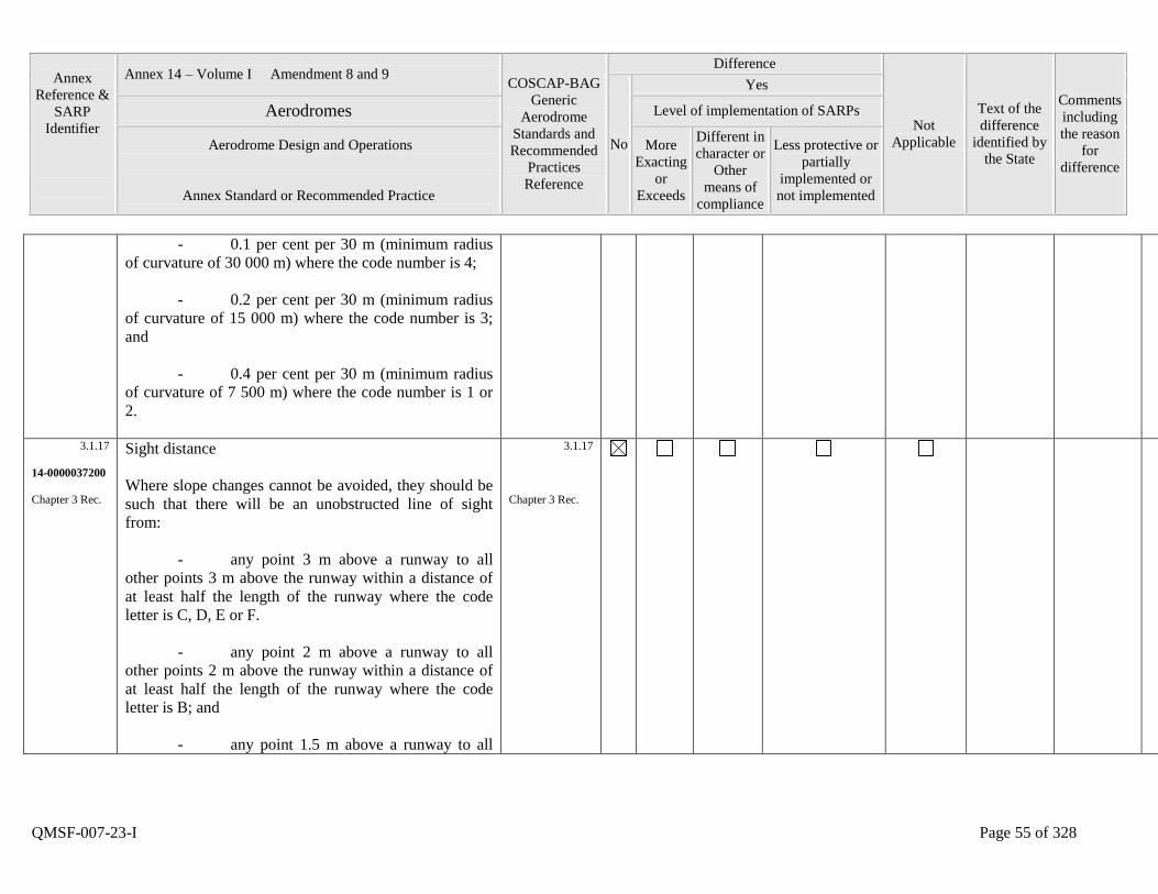
Annex
Reference &
SARP
Identifier
Annex 14 – Volume I Amendment 8 and 9 COSCAP-BAG
Generic
Aerodrome
Standards and
Recommended
Practices
Reference
Difference
Not
Applicable
Text of the
difference
identified by
the State
Comments
including
the reason
for
difference
No
Yes
Aerodromes Level of implementation of SARPs
Aerodrome Design and Operations
Annex Standard or Recommended Practice
More
Exacting
or
Exceeds
Different in
character or
Other
means of
compliance
Less protective or
partially
implemented or
not implemented
QMSF-007-23-I Page 55 of 328
- 0.1 per cent per 30 m (minimum radius
of curvature of 30 000 m) where the code number is 4;
- 0.2 per cent per 30 m (minimum radius
of curvature of 15 000 m) where the code number is 3;
and
- 0.4 per cent per 30 m (minimum radius
of curvature of 7 500 m) where the code number is 1 or
2.
3.1.17
14-0000037200
Chapter 3 Rec.
Sight distance
Where slope changes cannot be avoided, they should be
such that there will be an unobstructed line of sight
from:
- any point 3 m above a runway to all
other points 3 m above the runway within a distance of
at least half the length of the runway where the code
letter is C, D, E or F.
- any point 2 m above a runway to all
other points 2 m above the runway within a distance of
at least half the length of the runway where the code
letter is B; and
- any point 1.5 m above a runway to all
3.1.17
Chapter 3 Rec.
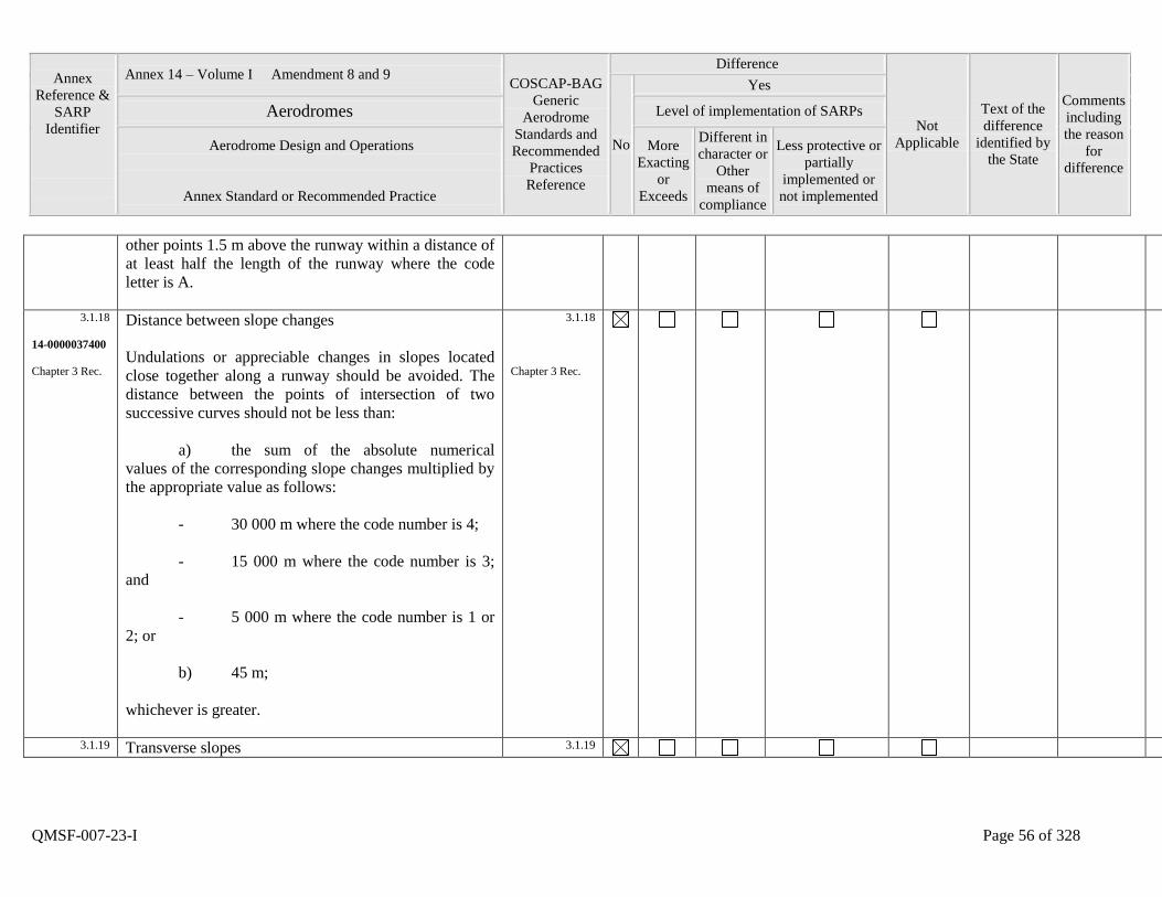
Annex
Reference &
SARP
Identifier
Annex 14 – Volume I Amendment 8 and 9 COSCAP-BAG
Generic
Aerodrome
Standards and
Recommended
Practices
Reference
Difference
Not
Applicable
Text of the
difference
identified by
the State
Comments
including
the reason
for
difference
No
Yes
Aerodromes Level of implementation of SARPs
Aerodrome Design and Operations
Annex Standard or Recommended Practice
More
Exacting
or
Exceeds
Different in
character or
Other
means of
compliance
Less protective or
partially
implemented or
not implemented
QMSF-007-23-I Page 56 of 328
other points 1.5 m above the runway within a distance of
at least half the length of the runway where the code
letter is A.
3.1.18
14-0000037400
Chapter 3 Rec.
Distance between slope changes
Undulations or appreciable changes in slopes located
close together along a runway should be avoided. The
distance between the points of intersection of two
successive curves should not be less than:
a) the sum of the absolute numerical
values of the corresponding slope changes multiplied by
the appropriate value as follows:
- 30 000 m where the code number is 4;
- 15 000 m where the code number is 3;
and
- 5 000 m where the code number is 1 or
2; or
b) 45 m;
whichever is greater.
3.1.18
Chapter 3 Rec.
3.1.19 Transverse slopes 3.1.19
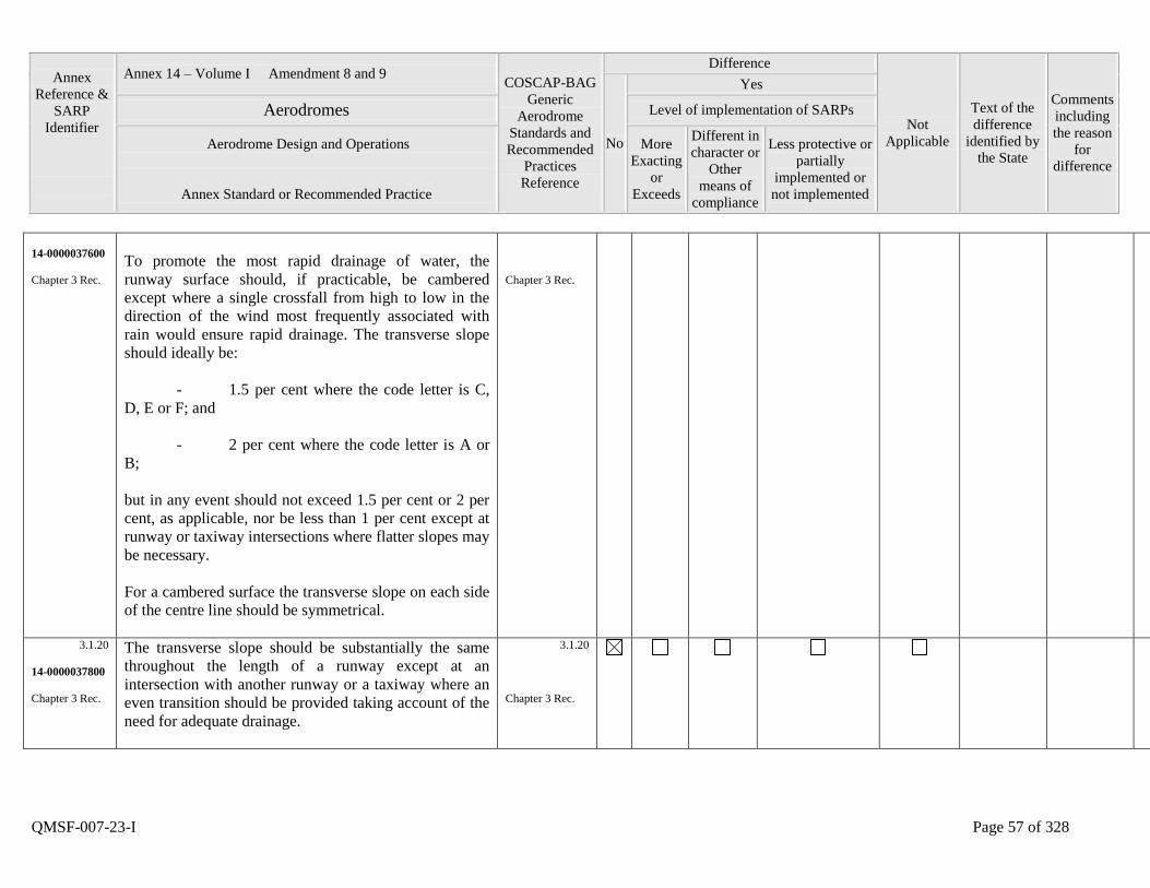
Annex
Reference &
SARP
Identifier
Annex 14 – Volume I Amendment 8 and 9 COSCAP-BAG
Generic
Aerodrome
Standards and
Recommended
Practices
Reference
Difference
Not
Applicable
Text of the
difference
identified by
the State
Comments
including
the reason
for
difference
No
Yes
Aerodromes Level of implementation of SARPs
Aerodrome Design and Operations
Annex Standard or Recommended Practice
More
Exacting
or
Exceeds
Different in
character or
Other
means of
compliance
Less protective or
partially
implemented or
not implemented
QMSF-007-23-I Page 57 of 328
14-0000037600
Chapter 3 Rec.
To promote the most rapid drainage of water, the
runway surface should, if practicable, be cambered
except where a single crossfall from high to low in the
direction of the wind most frequently associated with
rain would ensure rapid drainage. The transverse slope
should ideally be:
- 1.5 per cent where the code letter is C,
D, E or F; and
- 2 per cent where the code letter is A or
B;
but in any event should not exceed 1.5 per cent or 2 per
cent, as applicable, nor be less than 1 per cent except at
runway or taxiway intersections where flatter slopes may
be necessary.
For a cambered surface the transverse slope on each side
of the centre line should be symmetrical.
Chapter 3 Rec.
3.1.20
14-0000037800
Chapter 3 Rec.
The transverse slope should be substantially the same
throughout the length of a runway except at an
intersection with another runway or a taxiway where an
even transition should be provided taking account of the
need for adequate drainage.
3.1.20
Chapter 3 Rec.
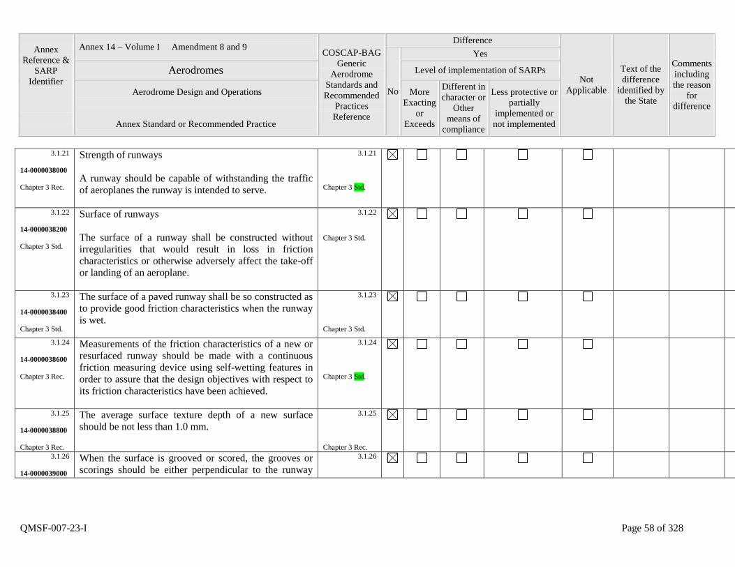
Annex
Reference &
SARP
Identifier
Annex 14 – Volume I Amendment 8 and 9 COSCAP-BAG
Generic
Aerodrome
Standards and
Recommended
Practices
Reference
Difference
Not
Applicable
Text of the
difference
identified by
the State
Comments
including
the reason
for
difference
No
Yes
Aerodromes Level of implementation of SARPs
Aerodrome Design and Operations
Annex Standard or Recommended Practice
More
Exacting
or
Exceeds
Different in
character or
Other
means of
compliance
Less protective or
partially
implemented or
not implemented
QMSF-007-23-I Page 58 of 328
3.1.21
14-0000038000
Chapter 3 Rec.
Strength of runways
A runway should be capable of withstanding the traffic
of aeroplanes the runway is intended to serve.
3.1.21
Chapter 3 Std.
3.1.22
14-0000038200
Chapter 3 Std.
Surface of runways
The surface of a runway shall be constructed without
irregularities that would result in loss in friction
characteristics or otherwise adversely affect the take-off
or landing of an aeroplane.
3.1.22
Chapter 3 Std.
3.1.23
14-0000038400
Chapter 3 Std.
The surface of a paved runway shall be so constructed as
to provide good friction characteristics when the runway
is wet.
3.1.23
Chapter 3 Std.
3.1.24
14-0000038600
Chapter 3 Rec.
Measurements of the friction characteristics of a new or
resurfaced runway should be made with a continuous
friction measuring device using self-wetting features in
order to assure that the design objectives with respect to
its friction characteristics have been achieved.
3.1.24
Chapter 3 Std.
3.1.25
14-0000038800
Chapter 3 Rec.
The average surface texture depth of a new surface
should be not less than 1.0 mm.
3.1.25
Chapter 3 Rec.
3.1.26
14-0000039000
When the surface is grooved or scored, the grooves or
scorings should be either perpendicular to the runway
3.1.26
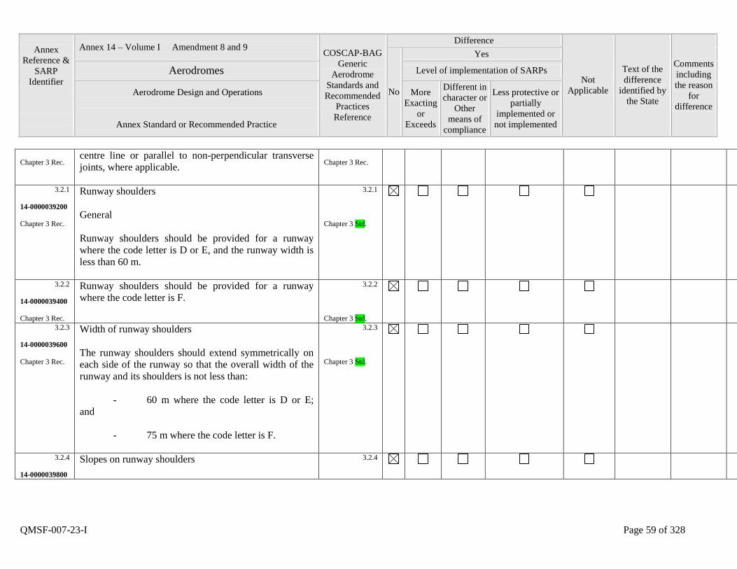
Annex
Reference &
SARP
Identifier
Annex 14 – Volume I Amendment 8 and 9 COSCAP-BAG
Generic
Aerodrome
Standards and
Recommended
Practices
Reference
Difference
Not
Applicable
Text of the
difference
identified by
the State
Comments
including
the reason
for
difference
No
Yes
Aerodromes Level of implementation of SARPs
Aerodrome Design and Operations
Annex Standard or Recommended Practice
More
Exacting
or
Exceeds
Different in
character or
Other
means of
compliance
Less protective or
partially
implemented or
not implemented
QMSF-007-23-I Page 59 of 328
Chapter 3 Rec. centre line or parallel to non-perpendicular transverse
joints, where applicable.
Chapter 3 Rec.
3.2.1
14-0000039200
Chapter 3 Rec.
Runway shoulders
General
Runway shoulders should be provided for a runway
where the code letter is D or E, and the runway width is
less than 60 m.
3.2.1
Chapter 3 Std.
3.2.2
14-0000039400
Chapter 3 Rec.
Runway shoulders should be provided for a runway
where the code letter is F.
3.2.2
Chapter 3 Std.
3.2.3
14-0000039600
Chapter 3 Rec.
Width of runway shoulders
The runway shoulders should extend symmetrically on
each side of the runway so that the overall width of the
runway and its shoulders is not less than:
- 60 m where the code letter is D or E;
and
- 75 m where the code letter is F.
3.2.3
Chapter 3 Std.
3.2.4
14-0000039800
Slopes on runway shoulders
3.2.4
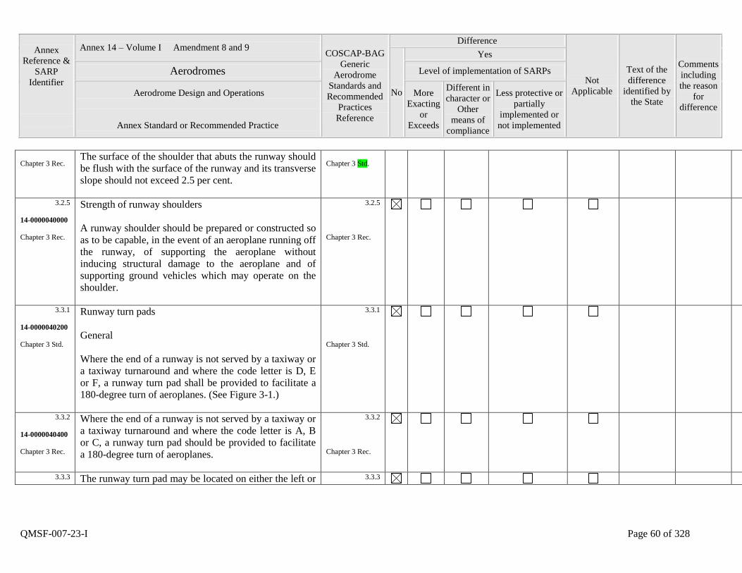
Annex
Reference &
SARP
Identifier
Annex 14 – Volume I Amendment 8 and 9 COSCAP-BAG
Generic
Aerodrome
Standards and
Recommended
Practices
Reference
Difference
Not
Applicable
Text of the
difference
identified by
the State
Comments
including
the reason
for
difference
No
Yes
Aerodromes Level of implementation of SARPs
Aerodrome Design and Operations
Annex Standard or Recommended Practice
More
Exacting
or
Exceeds
Different in
character or
Other
means of
compliance
Less protective or
partially
implemented or
not implemented
QMSF-007-23-I Page 60 of 328
Chapter 3 Rec. The surface of the shoulder that abuts the runway should
be flush with the surface of the runway and its transverse
slope should not exceed 2.5 per cent.
Chapter 3 Std.
3.2.5
14-0000040000
Chapter 3 Rec.
Strength of runway shoulders
A runway shoulder should be prepared or constructed so
as to be capable, in the event of an aeroplane running off
the runway, of supporting the aeroplane without
inducing structural damage to the aeroplane and of
supporting ground vehicles which may operate on the
shoulder.
3.2.5
Chapter 3 Rec.
3.3.1
14-0000040200
Chapter 3 Std.
Runway turn pads
General
Where the end of a runway is not served by a taxiway or
a taxiway turnaround and where the code letter is D, E
or F, a runway turn pad shall be provided to facilitate a
180-degree turn of aeroplanes. (See Figure 3-1.)
3.3.1
Chapter 3 Std.
3.3.2
14-0000040400
Chapter 3 Rec.
Where the end of a runway is not served by a taxiway or
a taxiway turnaround and where the code letter is A, B
or C, a runway turn pad should be provided to facilitate
a 180-degree turn of aeroplanes.
3.3.2
Chapter 3 Rec.
3.3.3 The runway turn pad may be located on either the left or 3.3.3
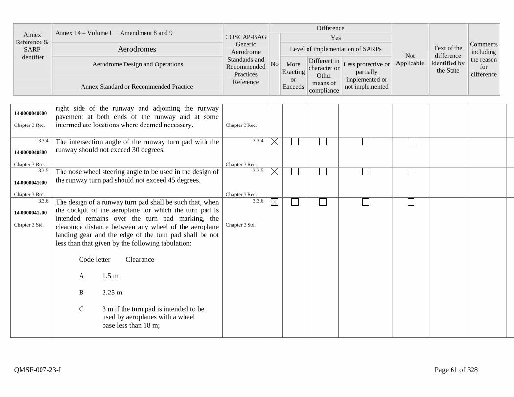
Annex
Reference &
SARP
Identifier
Annex 14 – Volume I Amendment 8 and 9 COSCAP-BAG
Generic
Aerodrome
Standards and
Recommended
Practices
Reference
Difference
Not
Applicable
Text of the
difference
identified by
the State
Comments
including
the reason
for
difference
No
Yes
Aerodromes Level of implementation of SARPs
Aerodrome Design and Operations
Annex Standard or Recommended Practice
More
Exacting
or
Exceeds
Different in
character or
Other
means of
compliance
Less protective or
partially
implemented or
not implemented
QMSF-007-23-I Page 61 of 328
14-0000040600
Chapter 3 Rec.
right side of the runway and adjoining the runway
pavement at both ends of the runway and at some
intermediate locations where deemed necessary.
Chapter 3 Rec.
3.3.4
14-0000040800
Chapter 3 Rec.
The intersection angle of the runway turn pad with the
runway should not exceed 30 degrees.
3.3.4
Chapter 3 Rec.
3.3.5
14-0000041000
Chapter 3 Rec.
The nose wheel steering angle to be used in the design of
the runway turn pad should not exceed 45 degrees.
3.3.5
Chapter 3 Rec.
3.3.6
14-0000041200
Chapter 3 Std.
The design of a runway turn pad shall be such that, when
the cockpit of the aeroplane for which the turn pad is
intended remains over the turn pad marking, the
clearance distance between any wheel of the aeroplane
landing gear and the edge of the turn pad shall be not
less than that given by the following tabulation:
Code letter Clearance
A 1.5 m
B 2.25 m
C 3 m if the turn pad is intended to be
used by aeroplanes with a wheel
base less than 18 m;
3.3.6
Chapter 3 Std.
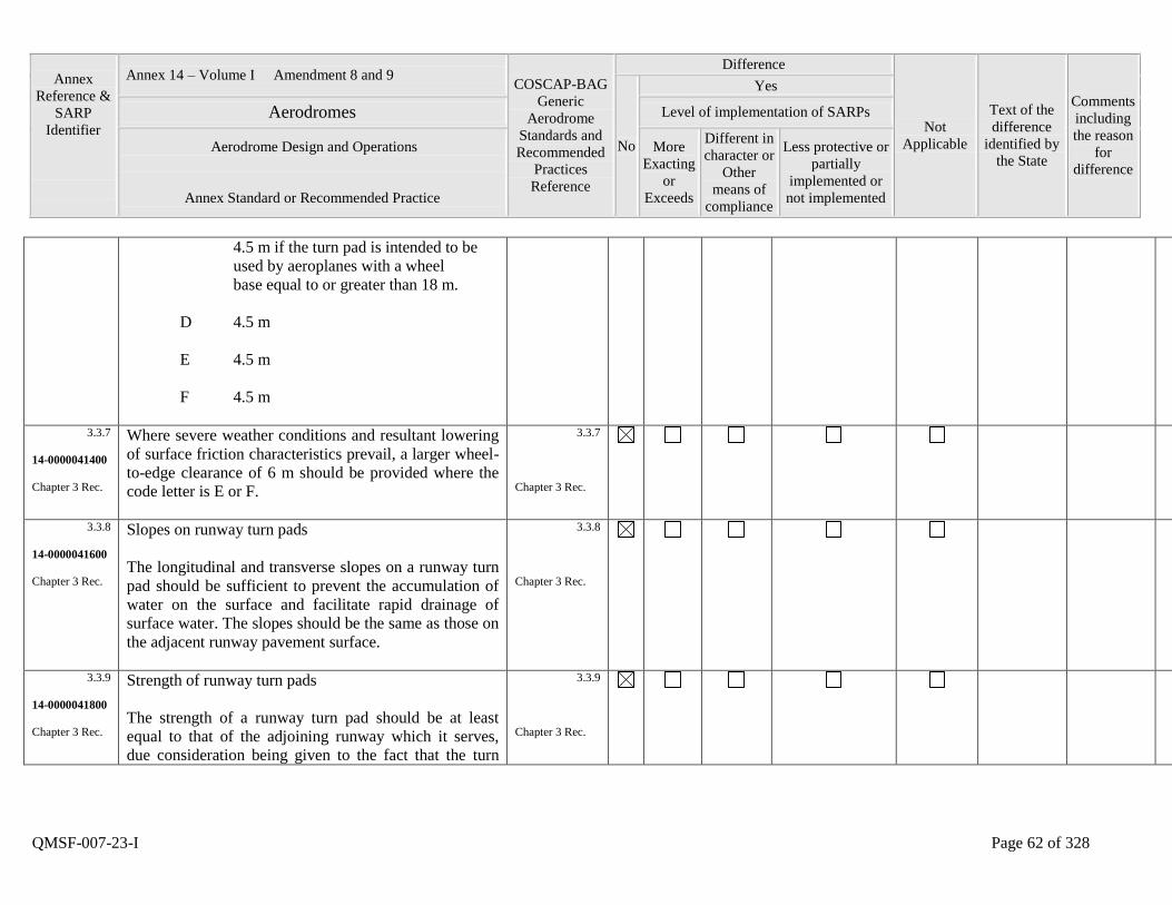
Annex
Reference &
SARP
Identifier
Annex 14 – Volume I Amendment 8 and 9 COSCAP-BAG
Generic
Aerodrome
Standards and
Recommended
Practices
Reference
Difference
Not
Applicable
Text of the
difference
identified by
the State
Comments
including
the reason
for
difference
No
Yes
Aerodromes Level of implementation of SARPs
Aerodrome Design and Operations
Annex Standard or Recommended Practice
More
Exacting
or
Exceeds
Different in
character or
Other
means of
compliance
Less protective or
partially
implemented or
not implemented
QMSF-007-23-I Page 62 of 328
4.5 m if the turn pad is intended to be
used by aeroplanes with a wheel
base equal to or greater than 18 m.
D 4.5 m
E 4.5 m
F 4.5 m
3.3.7
14-0000041400
Chapter 3 Rec.
Where severe weather conditions and resultant lowering
of surface friction characteristics prevail, a larger wheel-
to-edge clearance of 6 m should be provided where the
code letter is E or F.
3.3.7
Chapter 3 Rec.
3.3.8
14-0000041600
Chapter 3 Rec.
Slopes on runway turn pads
The longitudinal and transverse slopes on a runway turn
pad should be sufficient to prevent the accumulation of
water on the surface and facilitate rapid drainage of
surface water. The slopes should be the same as those on
the adjacent runway pavement surface.
3.3.8
Chapter 3 Rec.
3.3.9
14-0000041800
Chapter 3 Rec.
Strength of runway turn pads
The strength of a runway turn pad should be at least
equal to that of the adjoining runway which it serves,
due consideration being given to the fact that the turn
3.3.9
Chapter 3 Rec.
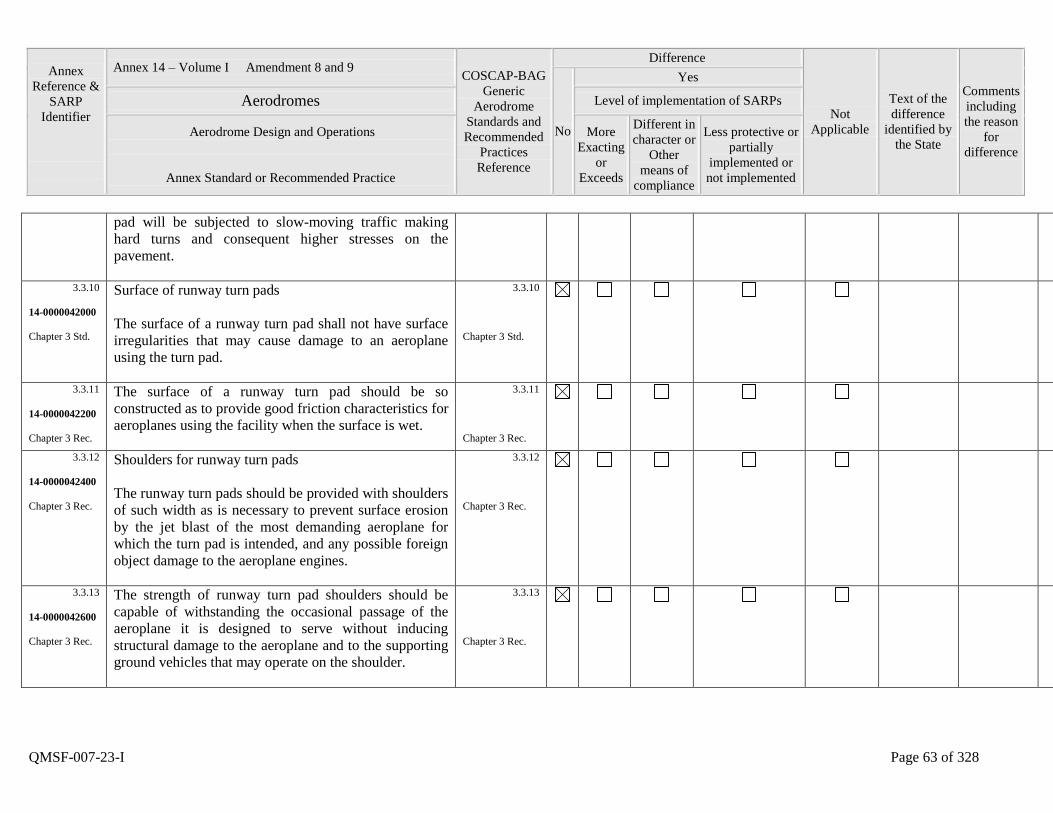
Annex
Reference &
SARP
Identifier
Annex 14 – Volume I Amendment 8 and 9 COSCAP-BAG
Generic
Aerodrome
Standards and
Recommended
Practices
Reference
Difference
Not
Applicable
Text of the
difference
identified by
the State
Comments
including
the reason
for
difference
No
Yes
Aerodromes Level of implementation of SARPs
Aerodrome Design and Operations
Annex Standard or Recommended Practice
More
Exacting
or
Exceeds
Different in
character or
Other
means of
compliance
Less protective or
partially
implemented or
not implemented
QMSF-007-23-I Page 63 of 328
pad will be subjected to slow-moving traffic making
hard turns and consequent higher stresses on the
pavement.
3.3.10
14-0000042000
Chapter 3 Std.
Surface of runway turn pads
The surface of a runway turn pad shall not have surface
irregularities that may cause damage to an aeroplane
using the turn pad.
3.3.10
Chapter 3 Std.
3.3.11
14-0000042200
Chapter 3 Rec.
The surface of a runway turn pad should be so
constructed as to provide good friction characteristics for
aeroplanes using the facility when the surface is wet.
3.3.11
Chapter 3 Rec.
3.3.12
14-0000042400
Chapter 3 Rec.
Shoulders for runway turn pads
The runway turn pads should be provided with shoulders
of such width as is necessary to prevent surface erosion
by the jet blast of the most demanding aeroplane for
which the turn pad is intended, and any possible foreign
object damage to the aeroplane engines.
3.3.12
Chapter 3 Rec.
3.3.13
14-0000042600
Chapter 3 Rec.
The strength of runway turn pad shoulders should be
capable of withstanding the occasional passage of the
aeroplane it is designed to serve without inducing
structural damage to the aeroplane and to the supporting
ground vehicles that may operate on the shoulder.
3.3.13
Chapter 3 Rec.
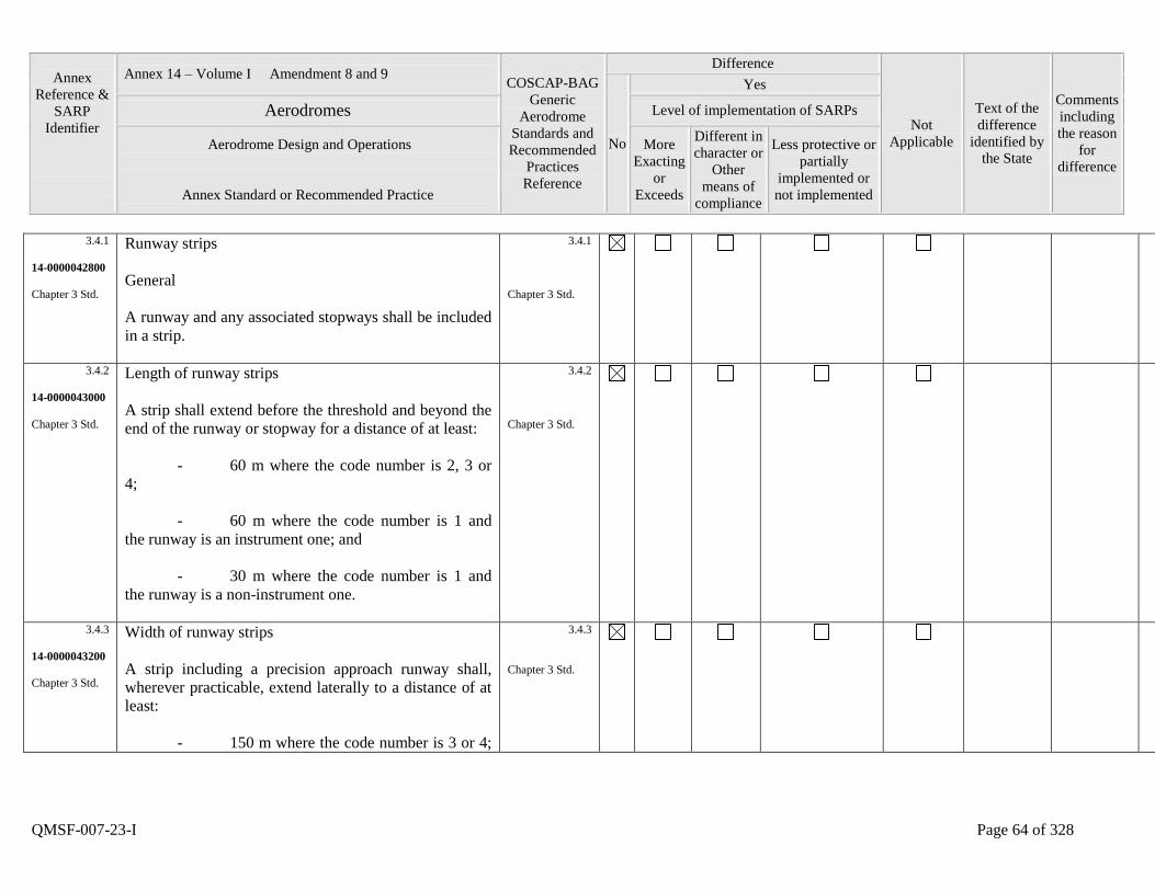
Annex
Reference &
SARP
Identifier
Annex 14 – Volume I Amendment 8 and 9 COSCAP-BAG
Generic
Aerodrome
Standards and
Recommended
Practices
Reference
Difference
Not
Applicable
Text of the
difference
identified by
the State
Comments
including
the reason
for
difference
No
Yes
Aerodromes Level of implementation of SARPs
Aerodrome Design and Operations
Annex Standard or Recommended Practice
More
Exacting
or
Exceeds
Different in
character or
Other
means of
compliance
Less protective or
partially
implemented or
not implemented
QMSF-007-23-I Page 64 of 328
3.4.1
14-0000042800
Chapter 3 Std.
Runway strips
General
A runway and any associated stopways shall be included
in a strip.
3.4.1
Chapter 3 Std.
3.4.2
14-0000043000
Chapter 3 Std.
Length of runway strips
A strip shall extend before the threshold and beyond the
end of the runway or stopway for a distance of at least:
- 60 m where the code number is 2, 3 or
4;
- 60 m where the code number is 1 and
the runway is an instrument one; and
- 30 m where the code number is 1 and
the runway is a non-instrument one.
3.4.2
Chapter 3 Std.
3.4.3
14-0000043200
Chapter 3 Std.
Width of runway strips
A strip including a precision approach runway shall,
wherever practicable, extend laterally to a distance of at
least:
- 150 m where the code number is 3 or 4;
3.4.3
Chapter 3 Std.
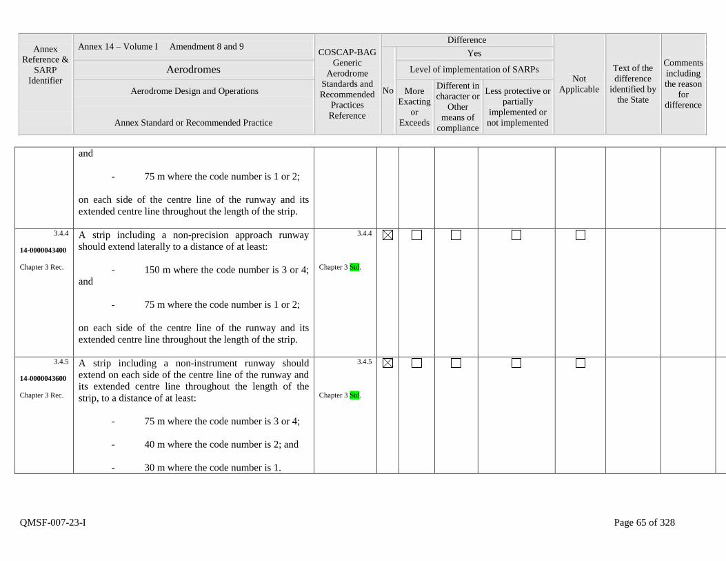
Annex
Reference &
SARP
Identifier
Annex 14 – Volume I Amendment 8 and 9 COSCAP-BAG
Generic
Aerodrome
Standards and
Recommended
Practices
Reference
Difference
Not
Applicable
Text of the
difference
identified by
the State
Comments
including
the reason
for
difference
No
Yes
Aerodromes Level of implementation of SARPs
Aerodrome Design and Operations
Annex Standard or Recommended Practice
More
Exacting
or
Exceeds
Different in
character or
Other
means of
compliance
Less protective or
partially
implemented or
not implemented
QMSF-007-23-I Page 65 of 328
and
- 75 m where the code number is 1 or 2;
on each side of the centre line of the runway and its
extended centre line throughout the length of the strip.
3.4.4
14-0000043400
Chapter 3 Rec.
A strip including a non-precision approach runway
should extend laterally to a distance of at least:
- 150 m where the code number is 3 or 4;
and
- 75 m where the code number is 1 or 2;
on each side of the centre line of the runway and its
extended centre line throughout the length of the strip.
3.4.4
Chapter 3 Std.
3.4.5
14-0000043600
Chapter 3 Rec.
A strip including a non-instrument runway should
extend on each side of the centre line of the runway and
its extended centre line throughout the length of the
strip, to a distance of at least:
- 75 m where the code number is 3 or 4;
- 40 m where the code number is 2; and
- 30 m where the code number is 1.
3.4.5
Chapter 3 Std.
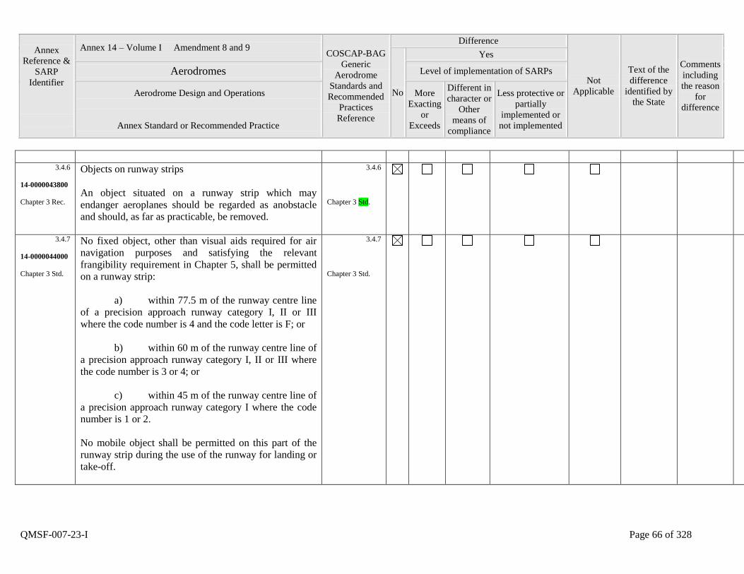
Annex
Reference &
SARP
Identifier
Annex 14 – Volume I Amendment 8 and 9 COSCAP-BAG
Generic
Aerodrome
Standards and
Recommended
Practices
Reference
Difference
Not
Applicable
Text of the
difference
identified by
the State
Comments
including
the reason
for
difference
No
Yes
Aerodromes Level of implementation of SARPs
Aerodrome Design and Operations
Annex Standard or Recommended Practice
More
Exacting
or
Exceeds
Different in
character or
Other
means of
compliance
Less protective or
partially
implemented or
not implemented
QMSF-007-23-I Page 66 of 328
3.4.6
14-0000043800
Chapter 3 Rec.
Objects on runway strips
An object situated on a runway strip which may
endanger aeroplanes should be regarded as anobstacle
and should, as far as practicable, be removed.
3.4.6
Chapter 3 Std.
3.4.7
14-0000044000
Chapter 3 Std.
No fixed object, other than visual aids required for air
navigation purposes and satisfying the relevant
frangibility requirement in Chapter 5, shall be permitted
on a runway strip:
a) within 77.5 m of the runway centre line
of a precision approach runway category I, II or III
where the code number is 4 and the code letter is F; or
b) within 60 m of the runway centre line of
a precision approach runway category I, II or III where
the code number is 3 or 4; or
c) within 45 m of the runway centre line of
a precision approach runway category I where the code
number is 1 or 2.
No mobile object shall be permitted on this part of the
runway strip during the use of the runway for landing or
take-off.
3.4.7
Chapter 3 Std.

Annex
Reference &
SARP
Identifier
Annex 14 – Volume I Amendment 8 and 9 COSCAP-BAG
Generic
Aerodrome
Standards and
Recommended
Practices
Reference
Difference
Not
Applicable
Text of the
difference
identified by
the State
Comments
including
the reason
for
difference
No
Yes
Aerodromes Level of implementation of SARPs
Aerodrome Design and Operations
Annex Standard or Recommended Practice
More
Exacting
or
Exceeds
Different in
character or
Other
means of
compliance
Less protective or
partially
implemented or
not implemented
QMSF-007-23-I Page 67 of 328
3.4.8
14-0000044200
Chapter 3 Rec.
Grading of runway strips
That portion of a strip of an instrument runway within a
distance of at least:
- 75 m where the code number is 3 or 4;
and
- 40 m where the code number is 1 or 2;
from the centre line of the runway and its extended
centre line should provide a graded area for aeroplanes
which the run-way is intended to serve in the event of an
aeroplane running off the runway.
3.4.8
Chapter 3 Std.
3.4.9
14-0000044400
Chapter 3 Rec.
That portion of a strip of a non-instrument runway
within a distance of at least:
- 75 m where the code number is 3 or 4;
- 40 m where the code number is 2; and
- 30 m where the code number is 1;
from the centre line of the runway and its extended
centre line should provide a graded area for aeroplanes
which the run-way is intended to serve in the event of an
aeroplane running off the runway.
3.4.9
Chapter 3 Std.
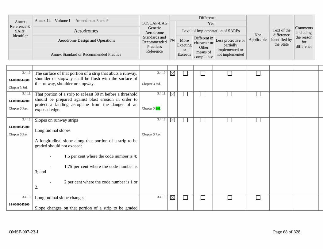
Annex
Reference &
SARP
Identifier
Annex 14 – Volume I Amendment 8 and 9 COSCAP-BAG
Generic
Aerodrome
Standards and
Recommended
Practices
Reference
Difference
Not
Applicable
Text of the
difference
identified by
the State
Comments
including
the reason
for
difference
No
Yes
Aerodromes Level of implementation of SARPs
Aerodrome Design and Operations
Annex Standard or Recommended Practice
More
Exacting
or
Exceeds
Different in
character or
Other
means of
compliance
Less protective or
partially
implemented or
not implemented
QMSF-007-23-I Page 68 of 328
3.4.10
14-0000044600
Chapter 3 Std.
The surface of that portion of a strip that abuts a runway,
shoulder or stopway shall be flush with the surface of
the runway, shoulder or stopway.
3.4.10
Chapter 3 Std.
3.4.11
14-0000044800
Chapter 3 Rec.
That portion of a strip to at least 30 m before a threshold
should be prepared against blast erosion in order to
protect a landing aeroplane from the danger of an
exposed edge.
3.4.11
Chapter 3 Std.
3.4.12
14-0000045000
Chapter 3 Rec.
Slopes on runway strips
Longitudinal slopes
A longitudinal slope along that portion of a strip to be
graded should not exceed:
- 1.5 per cent where the code number is 4;
- 1.75 per cent where the code number is
3; and
- 2 per cent where the code number is 1 or
2.
3.4.12
Chapter 3 Rec.
3.4.13
14-0000045200
Longitudinal slope changes
Slope changes on that portion of a strip to be graded
3.4.13
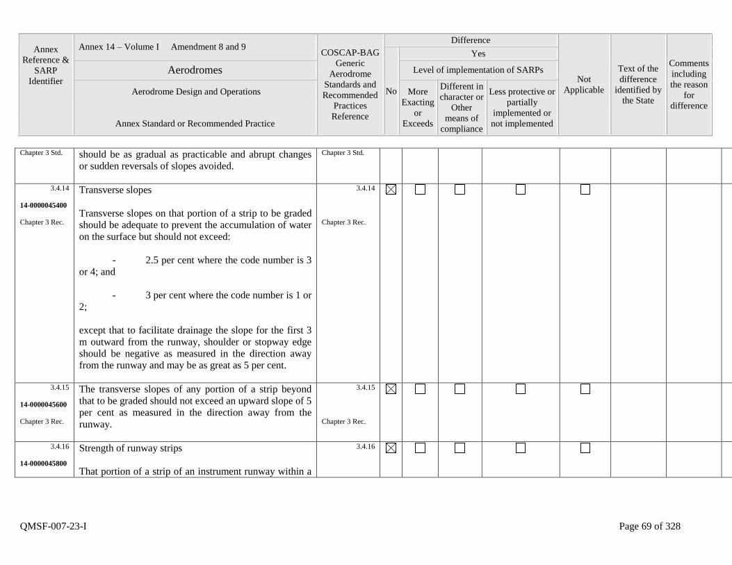
Annex
Reference &
SARP
Identifier
Annex 14 – Volume I Amendment 8 and 9 COSCAP-BAG
Generic
Aerodrome
Standards and
Recommended
Practices
Reference
Difference
Not
Applicable
Text of the
difference
identified by
the State
Comments
including
the reason
for
difference
No
Yes
Aerodromes Level of implementation of SARPs
Aerodrome Design and Operations
Annex Standard or Recommended Practice
More
Exacting
or
Exceeds
Different in
character or
Other
means of
compliance
Less protective or
partially
implemented or
not implemented
QMSF-007-23-I Page 69 of 328
Chapter 3 Std. should be as gradual as practicable and abrupt changes
or sudden reversals of slopes avoided.
Chapter 3 Std.
3.4.14
14-0000045400
Chapter 3 Rec.
Transverse slopes
Transverse slopes on that portion of a strip to be graded
should be adequate to prevent the accumulation of water
on the surface but should not exceed:
- 2.5 per cent where the code number is 3
or 4; and
- 3 per cent where the code number is 1 or
2;
except that to facilitate drainage the slope for the first 3
m outward from the runway, shoulder or stopway edge
should be negative as measured in the direction away
from the runway and may be as great as 5 per cent.
3.4.14
Chapter 3 Rec.
3.4.15
14-0000045600
Chapter 3 Rec.
The transverse slopes of any portion of a strip beyond
that to be graded should not exceed an upward slope of 5
per cent as measured in the direction away from the
runway.
3.4.15
Chapter 3 Rec.
3.4.16
14-0000045800
Strength of runway strips
That portion of a strip of an instrument runway within a
3.4.16
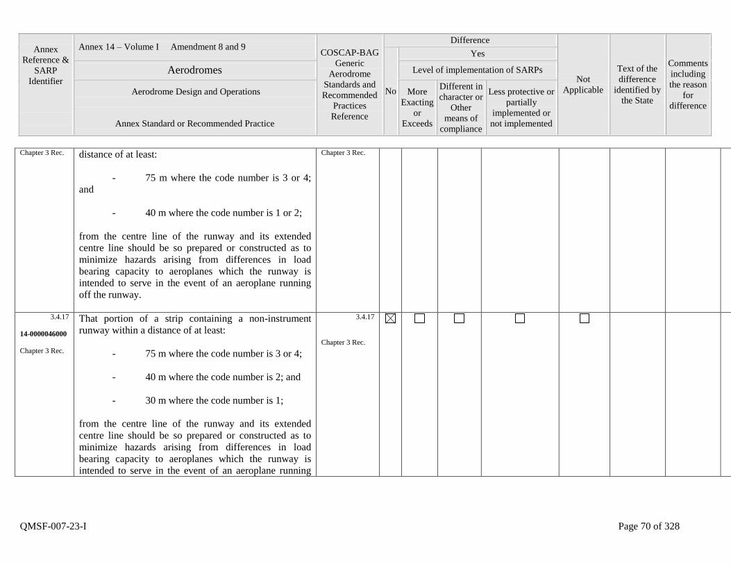
Annex
Reference &
SARP
Identifier
Annex 14 – Volume I Amendment 8 and 9 COSCAP-BAG
Generic
Aerodrome
Standards and
Recommended
Practices
Reference
Difference
Not
Applicable
Text of the
difference
identified by
the State
Comments
including
the reason
for
difference
No
Yes
Aerodromes Level of implementation of SARPs
Aerodrome Design and Operations
Annex Standard or Recommended Practice
More
Exacting
or
Exceeds
Different in
character or
Other
means of
compliance
Less protective or
partially
implemented or
not implemented
QMSF-007-23-I Page 70 of 328
Chapter 3 Rec. distance of at least:
- 75 m where the code number is 3 or 4;
and
- 40 m where the code number is 1 or 2;
from the centre line of the runway and its extended
centre line should be so prepared or constructed as to
minimize hazards arising from differences in load
bearing capacity to aeroplanes which the runway is
intended to serve in the event of an aeroplane running
off the runway.
Chapter 3 Rec.
3.4.17
14-0000046000
Chapter 3 Rec.
That portion of a strip containing a non-instrument
runway within a distance of at least:
- 75 m where the code number is 3 or 4;
- 40 m where the code number is 2; and
- 30 m where the code number is 1;
from the centre line of the runway and its extended
centre line should be so prepared or constructed as to
minimize hazards arising from differences in load
bearing capacity to aeroplanes which the runway is
intended to serve in the event of an aeroplane running
3.4.17
Chapter 3 Rec.
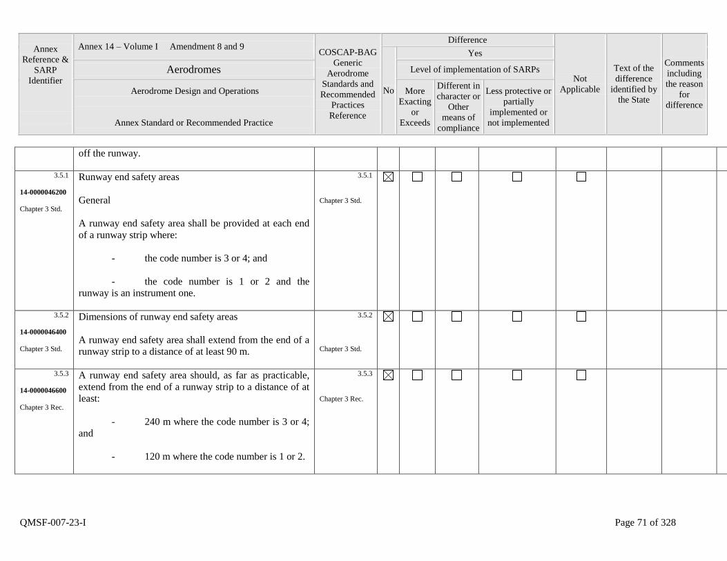
Annex
Reference &
SARP
Identifier
Annex 14 – Volume I Amendment 8 and 9 COSCAP-BAG
Generic
Aerodrome
Standards and
Recommended
Practices
Reference
Difference
Not
Applicable
Text of the
difference
identified by
the State
Comments
including
the reason
for
difference
No
Yes
Aerodromes Level of implementation of SARPs
Aerodrome Design and Operations
Annex Standard or Recommended Practice
More
Exacting
or
Exceeds
Different in
character or
Other
means of
compliance
Less protective or
partially
implemented or
not implemented
QMSF-007-23-I Page 71 of 328
off the runway.
3.5.1
14-0000046200
Chapter 3 Std.
Runway end safety areas
General
A runway end safety area shall be provided at each end
of a runway strip where:
- the code number is 3 or 4; and
- the code number is 1 or 2 and the
runway is an instrument one.
3.5.1
Chapter 3 Std.
3.5.2
14-0000046400
Chapter 3 Std.
Dimensions of runway end safety areas
A runway end safety area shall extend from the end of a
runway strip to a distance of at least 90 m.
3.5.2
Chapter 3 Std.
3.5.3
14-0000046600
Chapter 3 Rec.
A runway end safety area should, as far as practicable,
extend from the end of a runway strip to a distance of at
least:
- 240 m where the code number is 3 or 4;
and
- 120 m where the code number is 1 or 2.
3.5.3
Chapter 3 Rec.
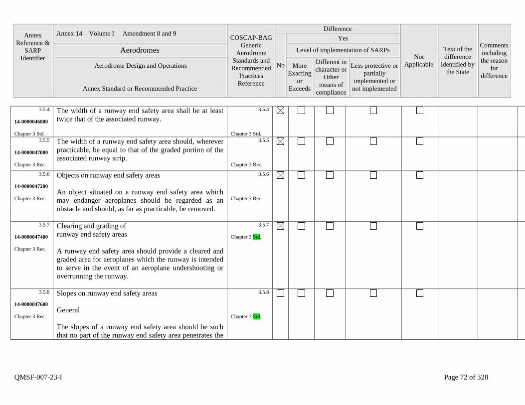
Annex
Reference &
SARP
Identifier
Annex 14 – Volume I Amendment 8 and 9 COSCAP-BAG
Generic
Aerodrome
Standards and
Recommended
Practices
Reference
Difference
Not
Applicable
Text of the
difference
identified by
the State
Comments
including
the reason
for
difference
No
Yes
Aerodromes Level of implementation of SARPs
Aerodrome Design and Operations
Annex Standard or Recommended Practice
More
Exacting
or
Exceeds
Different in
character or
Other
means of
compliance
Less protective or
partially
implemented or
not implemented
QMSF-007-23-I Page 72 of 328
3.5.4
14-0000046800
Chapter 3 Std.
The width of a runway end safety area shall be at least
twice that of the associated runway.
3.5.4
Chapter 3 Std.
3.5.5
14-0000047000
Chapter 3 Rec.
The width of a runway end safety area should, wherever
practicable, be equal to that of the graded portion of the
associated runway strip.
3.5.5
Chapter 3 Rec.
3.5.6
14-0000047200
Chapter 3 Rec.
Objects on runway end safety areas
An object situated on a runway end safety area which
may endanger aeroplanes should be regarded as an
obstacle and should, as far as practicable, be removed.
3.5.6
Chapter 3 Rec.
3.5.7
14-0000047400
Chapter 3 Rec.
Clearing and grading of
runway end safety areas
A runway end safety area should provide a cleared and
graded area for aeroplanes which the runway is intended
to serve in the event of an aeroplane undershooting or
overrunning the runway.
3.5.7
Chapter 3 Std.
3.5.8
14-0000047600
Chapter 3 Rec.
Slopes on runway end safety areas
General
The slopes of a runway end safety area should be such
that no part of the runway end safety area penetrates the
3.5.8
Chapter 3 Std.
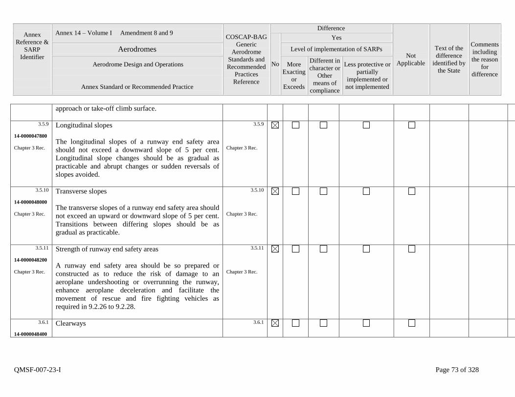
Annex
Reference &
SARP
Identifier
Annex 14 – Volume I Amendment 8 and 9 COSCAP-BAG
Generic
Aerodrome
Standards and
Recommended
Practices
Reference
Difference
Not
Applicable
Text of the
difference
identified by
the State
Comments
including
the reason
for
difference
No
Yes
Aerodromes Level of implementation of SARPs
Aerodrome Design and Operations
Annex Standard or Recommended Practice
More
Exacting
or
Exceeds
Different in
character or
Other
means of
compliance
Less protective or
partially
implemented or
not implemented
QMSF-007-23-I Page 73 of 328
approach or take-off climb surface.
3.5.9
14-0000047800
Chapter 3 Rec.
Longitudinal slopes
The longitudinal slopes of a runway end safety area
should not exceed a downward slope of 5 per cent.
Longitudinal slope changes should be as gradual as
practicable and abrupt changes or sudden reversals of
slopes avoided.
3.5.9
Chapter 3 Rec.
3.5.10
14-0000048000
Chapter 3 Rec.
Transverse slopes
The transverse slopes of a runway end safety area should
not exceed an upward or downward slope of 5 per cent.
Transitions between differing slopes should be as
gradual as practicable.
3.5.10
Chapter 3 Rec.
3.5.11
14-0000048200
Chapter 3 Rec.
Strength of runway end safety areas
A runway end safety area should be so prepared or
constructed as to reduce the risk of damage to an
aeroplane undershooting or overrunning the runway,
enhance aeroplane deceleration and facilitate the
movement of rescue and fire fighting vehicles as
required in 9.2.26 to 9.2.28.
3.5.11
Chapter 3 Rec.
3.6.1
14-0000048400
Clearways
3.6.1
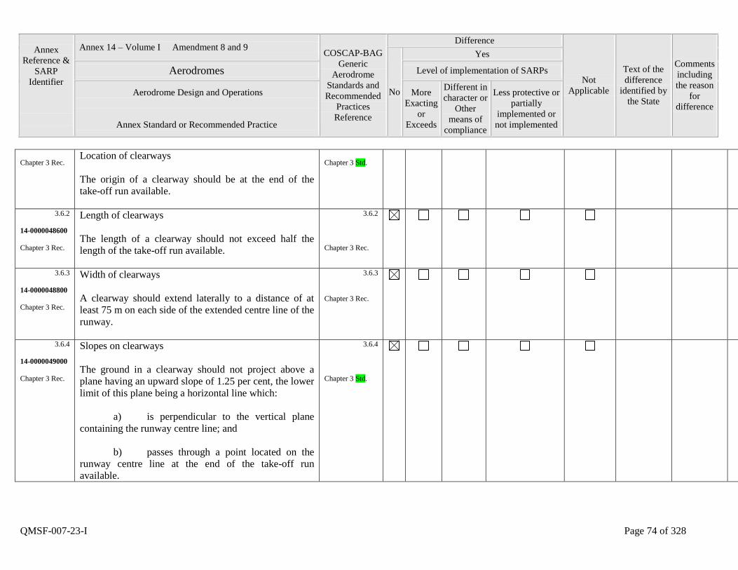
Annex
Reference &
SARP
Identifier
Annex 14 – Volume I Amendment 8 and 9 COSCAP-BAG
Generic
Aerodrome
Standards and
Recommended
Practices
Reference
Difference
Not
Applicable
Text of the
difference
identified by
the State
Comments
including
the reason
for
difference
No
Yes
Aerodromes Level of implementation of SARPs
Aerodrome Design and Operations
Annex Standard or Recommended Practice
More
Exacting
or
Exceeds
Different in
character or
Other
means of
compliance
Less protective or
partially
implemented or
not implemented
QMSF-007-23-I Page 74 of 328
Chapter 3 Rec. Location of clearways
The origin of a clearway should be at the end of the
take-off run available.
Chapter 3 Std.
3.6.2
14-0000048600
Chapter 3 Rec.
Length of clearways
The length of a clearway should not exceed half the
length of the take-off run available.
3.6.2
Chapter 3 Rec.
3.6.3
14-0000048800
Chapter 3 Rec.
Width of clearways
A clearway should extend laterally to a distance of at
least 75 m on each side of the extended centre line of the
runway.
3.6.3
Chapter 3 Rec.
3.6.4
14-0000049000
Chapter 3 Rec.
Slopes on clearways
The ground in a clearway should not project above a
plane having an upward slope of 1.25 per cent, the lower
limit of this plane being a horizontal line which:
a) is perpendicular to the vertical plane
containing the runway centre line; and
b) passes through a point located on the
runway centre line at the end of the take-off run
available.
3.6.4
Chapter 3 Std.
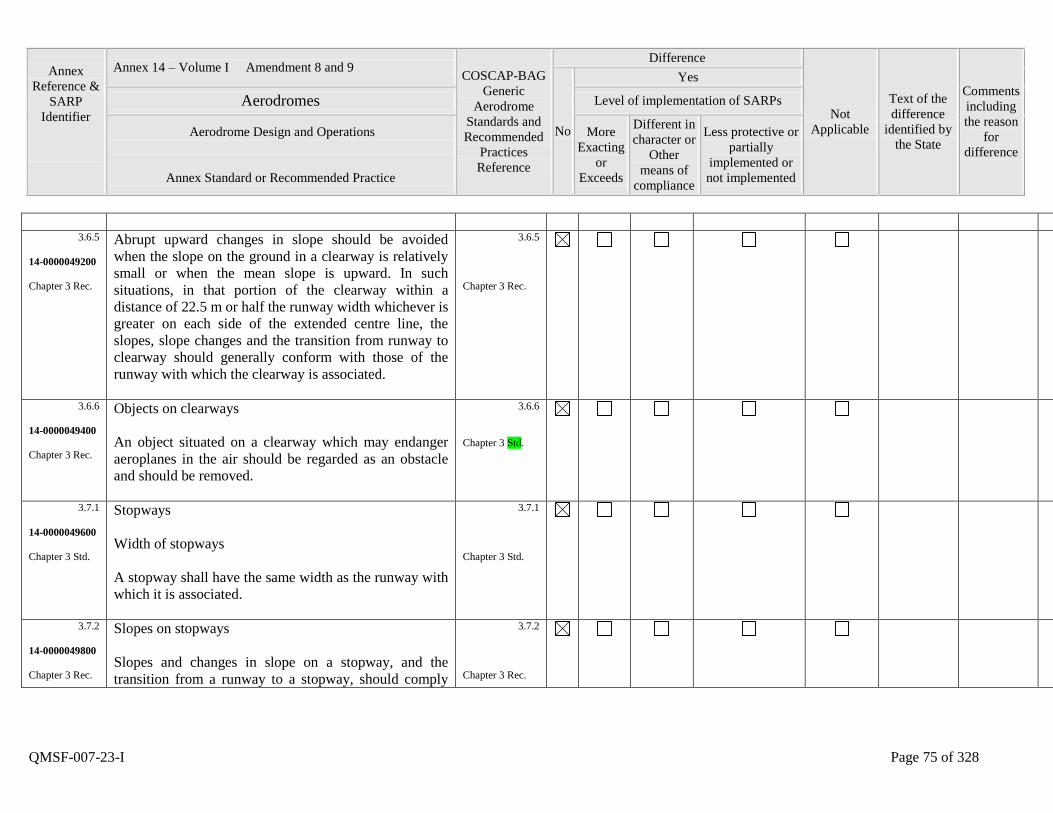
Annex
Reference &
SARP
Identifier
Annex 14 – Volume I Amendment 8 and 9 COSCAP-BAG
Generic
Aerodrome
Standards and
Recommended
Practices
Reference
Difference
Not
Applicable
Text of the
difference
identified by
the State
Comments
including
the reason
for
difference
No
Yes
Aerodromes Level of implementation of SARPs
Aerodrome Design and Operations
Annex Standard or Recommended Practice
More
Exacting
or
Exceeds
Different in
character or
Other
means of
compliance
Less protective or
partially
implemented or
not implemented
QMSF-007-23-I Page 75 of 328
3.6.5
14-0000049200
Chapter 3 Rec.
Abrupt upward changes in slope should be avoided
when the slope on the ground in a clearway is relatively
small or when the mean slope is upward. In such
situations, in that portion of the clearway within a
distance of 22.5 m or half the runway width whichever is
greater on each side of the extended centre line, the
slopes, slope changes and the transition from runway to
clearway should generally conform with those of the
runway with which the clearway is associated.
3.6.5
Chapter 3 Rec.
3.6.6
14-0000049400
Chapter 3 Rec.
Objects on clearways
An object situated on a clearway which may endanger
aeroplanes in the air should be regarded as an obstacle
and should be removed.
3.6.6
Chapter 3 Std.
3.7.1
14-0000049600
Chapter 3 Std.
Stopways
Width of stopways
A stopway shall have the same width as the runway with
which it is associated.
3.7.1
Chapter 3 Std.
3.7.2
14-0000049800
Chapter 3 Rec.
Slopes on stopways
Slopes and changes in slope on a stopway, and the
transition from a runway to a stopway, should comply
3.7.2
Chapter 3 Rec.
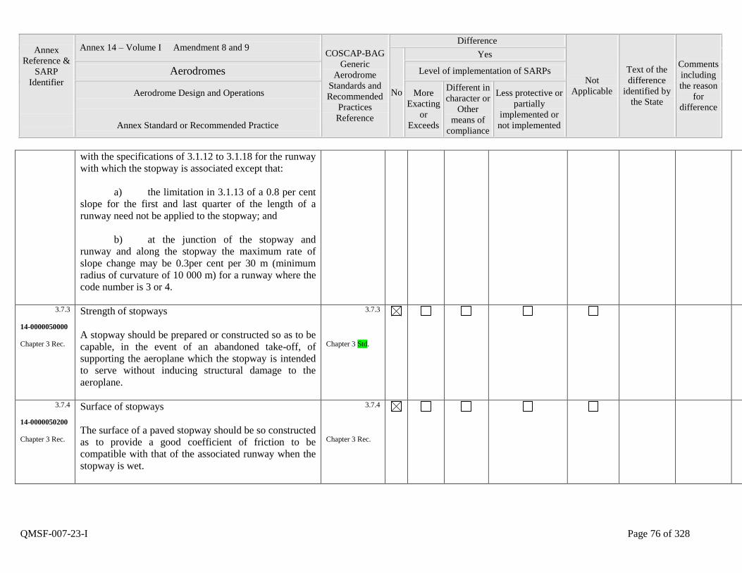
Annex
Reference &
SARP
Identifier
Annex 14 – Volume I Amendment 8 and 9 COSCAP-BAG
Generic
Aerodrome
Standards and
Recommended
Practices
Reference
Difference
Not
Applicable
Text of the
difference
identified by
the State
Comments
including
the reason
for
difference
No
Yes
Aerodromes Level of implementation of SARPs
Aerodrome Design and Operations
Annex Standard or Recommended Practice
More
Exacting
or
Exceeds
Different in
character or
Other
means of
compliance
Less protective or
partially
implemented or
not implemented
QMSF-007-23-I Page 76 of 328
with the specifications of 3.1.12 to 3.1.18 for the runway
with which the stopway is associated except that:
a) the limitation in 3.1.13 of a 0.8 per cent
slope for the first and last quarter of the length of a
runway need not be applied to the stopway; and
b) at the junction of the stopway and
runway and along the stopway the maximum rate of
slope change may be 0.3per cent per 30 m (minimum
radius of curvature of 10 000 m) for a runway where the
code number is 3 or 4.
3.7.3
14-0000050000
Chapter 3 Rec.
Strength of stopways
A stopway should be prepared or constructed so as to be
capable, in the event of an abandoned take-off, of
supporting the aeroplane which the stopway is intended
to serve without inducing structural damage to the
aeroplane.
3.7.3
Chapter 3 Std.
3.7.4
14-0000050200
Chapter 3 Rec.
Surface of stopways
The surface of a paved stopway should be so constructed
as to provide a good coefficient of friction to be
compatible with that of the associated runway when the
stopway is wet.
3.7.4
Chapter 3 Rec.
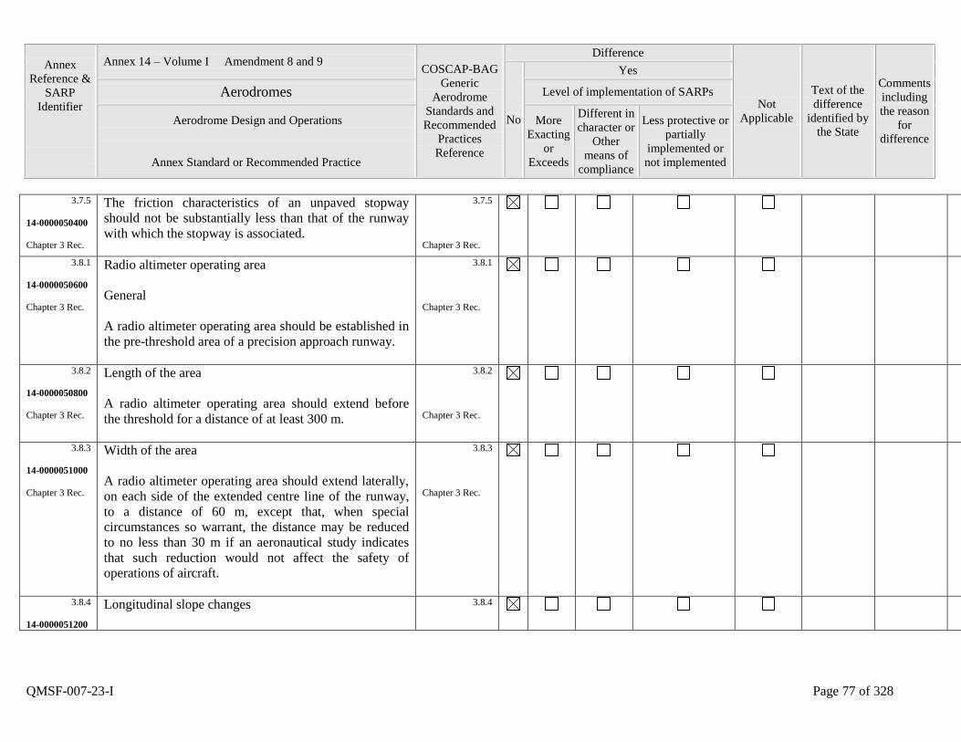
Annex
Reference &
SARP
Identifier
Annex 14 – Volume I Amendment 8 and 9 COSCAP-BAG
Generic
Aerodrome
Standards and
Recommended
Practices
Reference
Difference
Not
Applicable
Text of the
difference
identified by
the State
Comments
including
the reason
for
difference
No
Yes
Aerodromes Level of implementation of SARPs
Aerodrome Design and Operations
Annex Standard or Recommended Practice
More
Exacting
or
Exceeds
Different in
character or
Other
means of
compliance
Less protective or
partially
implemented or
not implemented
QMSF-007-23-I Page 77 of 328
3.7.5
14-0000050400
Chapter 3 Rec.
The friction characteristics of an unpaved stopway
should not be substantially less than that of the runway
with which the stopway is associated.
3.7.5
Chapter 3 Rec.
3.8.1
14-0000050600
Chapter 3 Rec.
Radio altimeter operating area
General
A radio altimeter operating area should be established in
the pre-threshold area of a precision approach runway.
3.8.1
Chapter 3 Rec.
3.8.2
14-0000050800
Chapter 3 Rec.
Length of the area
A radio altimeter operating area should extend before
the threshold for a distance of at least 300 m.
3.8.2
Chapter 3 Rec.
3.8.3
14-0000051000
Chapter 3 Rec.
Width of the area
A radio altimeter operating area should extend laterally,
on each side of the extended centre line of the runway,
to a distance of 60 m, except that, when special
circumstances so warrant, the distance may be reduced
to no less than 30 m if an aeronautical study indicates
that such reduction would not affect the safety of
operations of aircraft.
3.8.3
Chapter 3 Rec.
3.8.4
14-0000051200
Longitudinal slope changes
3.8.4
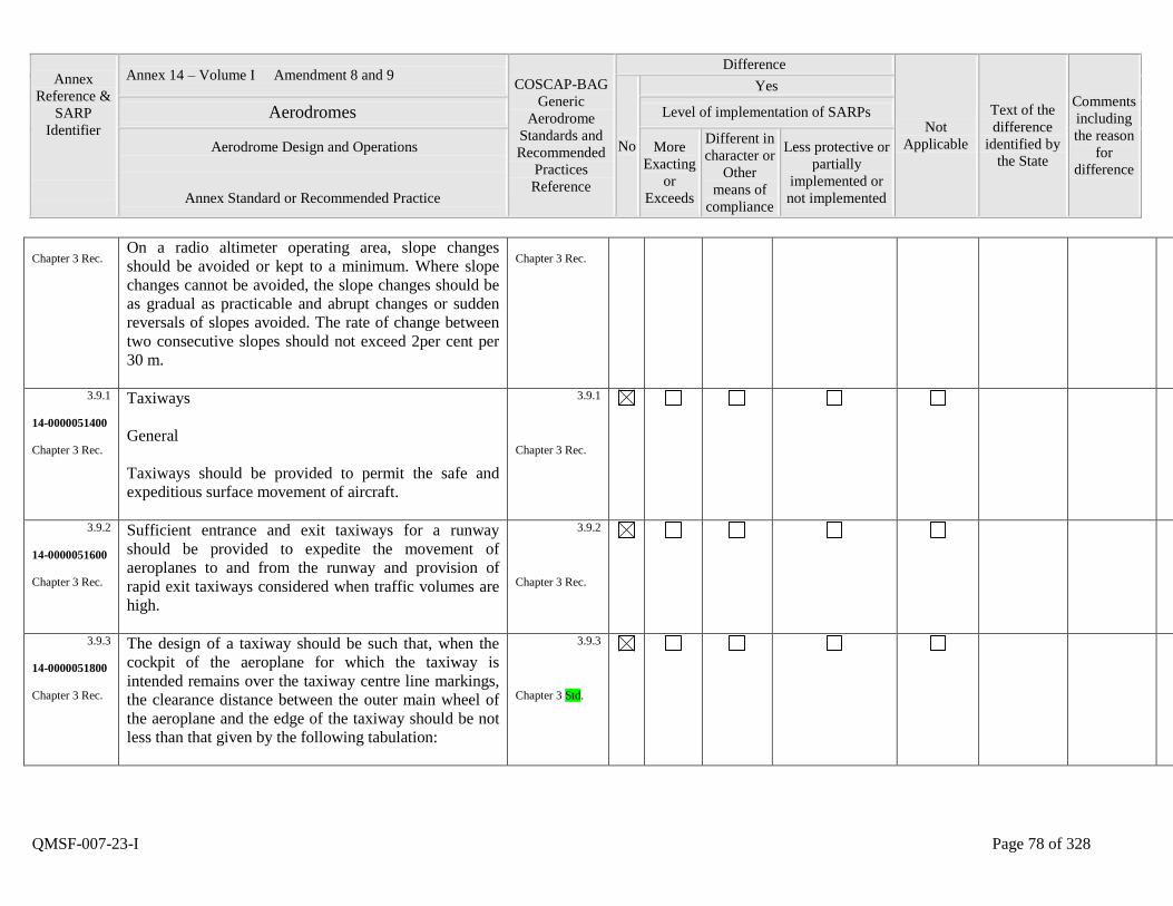
Annex
Reference &
SARP
Identifier
Annex 14 – Volume I Amendment 8 and 9 COSCAP-BAG
Generic
Aerodrome
Standards and
Recommended
Practices
Reference
Difference
Not
Applicable
Text of the
difference
identified by
the State
Comments
including
the reason
for
difference
No
Yes
Aerodromes Level of implementation of SARPs
Aerodrome Design and Operations
Annex Standard or Recommended Practice
More
Exacting
or
Exceeds
Different in
character or
Other
means of
compliance
Less protective or
partially
implemented or
not implemented
QMSF-007-23-I Page 78 of 328
Chapter 3 Rec. On a radio altimeter operating area, slope changes
should be avoided or kept to a minimum. Where slope
changes cannot be avoided, the slope changes should be
as gradual as practicable and abrupt changes or sudden
reversals of slopes avoided. The rate of change between
two consecutive slopes should not exceed 2per cent per
30 m.
Chapter 3 Rec.
3.9.1
14-0000051400
Chapter 3 Rec.
Taxiways
General
Taxiways should be provided to permit the safe and
expeditious surface movement of aircraft.
3.9.1
Chapter 3 Rec.
3.9.2
14-0000051600
Chapter 3 Rec.
Sufficient entrance and exit taxiways for a runway
should be provided to expedite the movement of
aeroplanes to and from the runway and provision of
rapid exit taxiways considered when traffic volumes are
high.
3.9.2
Chapter 3 Rec.
3.9.3
14-0000051800
Chapter 3 Rec.
The design of a taxiway should be such that, when the
cockpit of the aeroplane for which the taxiway is
intended remains over the taxiway centre line markings,
the clearance distance between the outer main wheel of
the aeroplane and the edge of the taxiway should be not
less than that given by the following tabulation:
3.9.3
Chapter 3 Std.
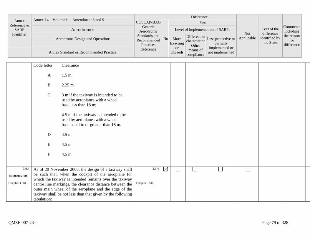
Annex
Reference &
SARP
Identifier
Annex 14 – Volume I Amendment 8 and 9 COSCAP-BAG
Generic
Aerodrome
Standards and
Recommended
Practices
Reference
Difference
Not
Applicable
Text of the
difference
identified by
the State
Comments
including
the reason
for
difference
No
Yes
Aerodromes Level of implementation of SARPs
Aerodrome Design and Operations
Annex Standard or Recommended Practice
More
Exacting
or
Exceeds
Different in
character or
Other
means of
compliance
Less protective or
partially
implemented or
not implemented
QMSF-007-23-I Page 79 of 328
Code letter Clearance
A 1.5 m
B 2.25 m
C 3 m if the taxiway is intended to be
used by aeroplanes with a wheel
base less than 18 m;
4.5 m if the taxiway is intended to be
used by aeroplanes with a wheel
base equal to or greater than 18 m.
D 4.5 m
E 4.5 m
F 4.5 m
3.9.4
14-0000051900
Chapter 3 Std.
As of 20 November 2008, the design of a taxiway shall
be such that, when the cockpit of the aeroplane for
which the taxiway is intended remains over the taxiway
centre line markings, the clearance distance between the
outer main wheel of the aeroplane and the edge of the
taxiway shall be not less than that given by the following
tabulation:
3.9.4
Chapter 3 Std.
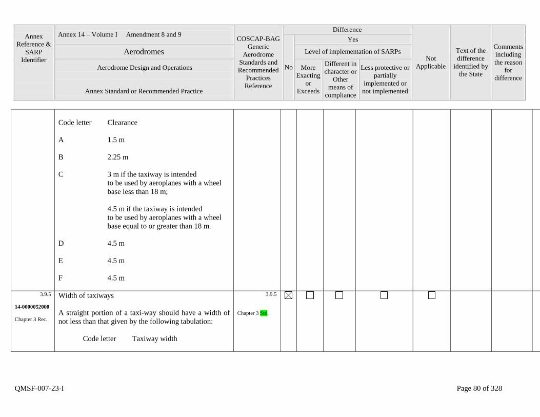
Annex
Reference &
SARP
Identifier
Annex 14 – Volume I Amendment 8 and 9 COSCAP-BAG
Generic
Aerodrome
Standards and
Recommended
Practices
Reference
Difference
Not
Applicable
Text of the
difference
identified by
the State
Comments
including
the reason
for
difference
No
Yes
Aerodromes Level of implementation of SARPs
Aerodrome Design and Operations
Annex Standard or Recommended Practice
More
Exacting
or
Exceeds
Different in
character or
Other
means of
compliance
Less protective or
partially
implemented or
not implemented
QMSF-007-23-I Page 80 of 328
Code letter Clearance
A 1.5 m
B 2.25 m
C 3 m if the taxiway is intended
to be used by aeroplanes with a wheel
base less than 18 m;
4.5 m if the taxiway is intended
to be used by aeroplanes with a wheel
base equal to or greater than 18 m.
D 4.5 m
E 4.5 m
F 4.5 m
3.9.5
14-0000052000
Chapter 3 Rec.
Width of taxiways
A straight portion of a taxi-way should have a width of
not less than that given by the following tabulation:
Code letter Taxiway width
3.9.5
Chapter 3 Std.
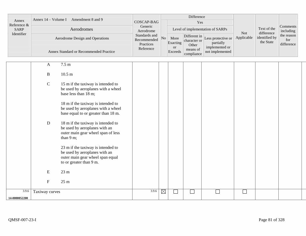
Annex
Reference &
SARP
Identifier
Annex 14 – Volume I Amendment 8 and 9 COSCAP-BAG
Generic
Aerodrome
Standards and
Recommended
Practices
Reference
Difference
Not
Applicable
Text of the
difference
identified by
the State
Comments
including
the reason
for
difference
No
Yes
Aerodromes Level of implementation of SARPs
Aerodrome Design and Operations
Annex Standard or Recommended Practice
More
Exacting
or
Exceeds
Different in
character or
Other
means of
compliance
Less protective or
partially
implemented or
not implemented
QMSF-007-23-I Page 81 of 328
A 7.5 m
B 10.5 m
C 15 m if the taxiway is intended to
be used by aeroplanes with a wheel
base less than 18 m;
18 m if the taxiway is intended to
be used by aeroplanes with a wheel
base equal to or greater than 18 m.
D 18 m if the taxiway is intended to
be used by aeroplanes with an
outer main gear wheel span of less
than 9 m;
23 m if the taxiway is intended to
be used by aeroplanes with an
outer main gear wheel span equal
to or greater than 9 m.
E 23 m
F 25 m
3.9.6
14-0000052200
Taxiway curves
3.9.6
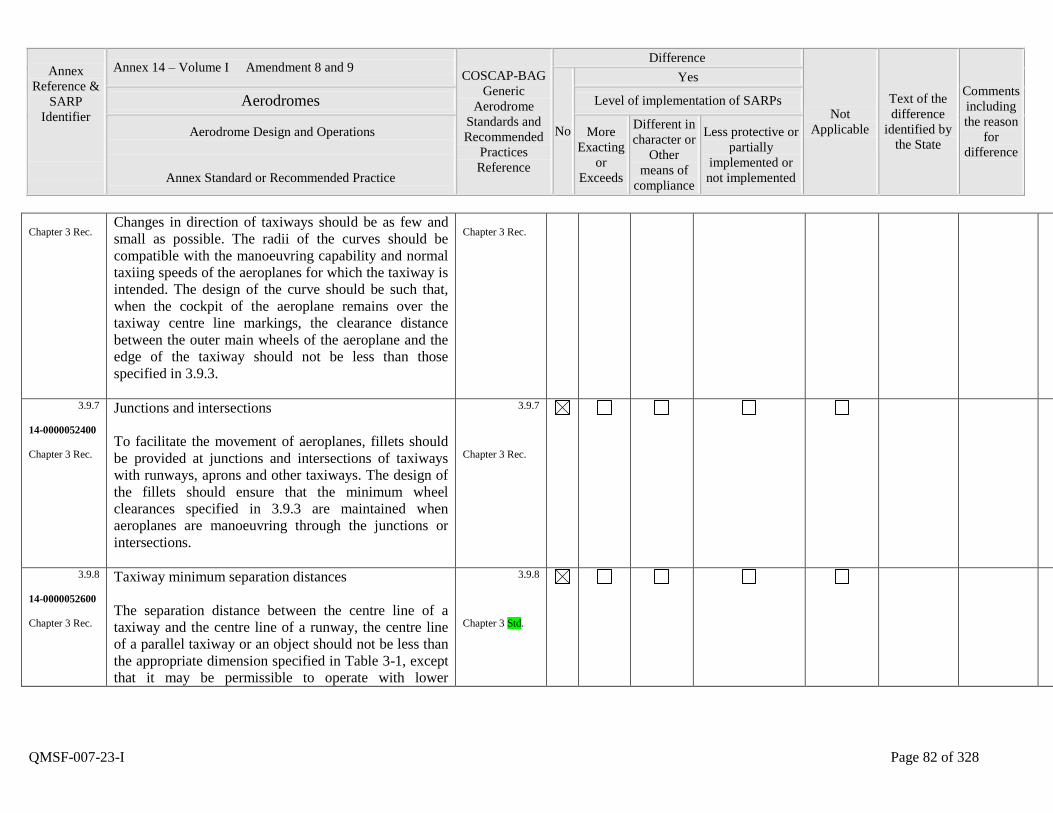
Annex
Reference &
SARP
Identifier
Annex 14 – Volume I Amendment 8 and 9 COSCAP-BAG
Generic
Aerodrome
Standards and
Recommended
Practices
Reference
Difference
Not
Applicable
Text of the
difference
identified by
the State
Comments
including
the reason
for
difference
No
Yes
Aerodromes Level of implementation of SARPs
Aerodrome Design and Operations
Annex Standard or Recommended Practice
More
Exacting
or
Exceeds
Different in
character or
Other
means of
compliance
Less protective or
partially
implemented or
not implemented
QMSF-007-23-I Page 82 of 328
Chapter 3 Rec. Changes in direction of taxiways should be as few and
small as possible. The radii of the curves should be
compatible with the manoeuvring capability and normal
taxiing speeds of the aeroplanes for which the taxiway is
intended. The design of the curve should be such that,
when the cockpit of the aeroplane remains over the
taxiway centre line markings, the clearance distance
between the outer main wheels of the aeroplane and the
edge of the taxiway should not be less than those
specified in 3.9.3.
Chapter 3 Rec.
3.9.7
14-0000052400
Chapter 3 Rec.
Junctions and intersections
To facilitate the movement of aeroplanes, fillets should
be provided at junctions and intersections of taxiways
with runways, aprons and other taxiways. The design of
the fillets should ensure that the minimum wheel
clearances specified in 3.9.3 are maintained when
aeroplanes are manoeuvring through the junctions or
intersections.
3.9.7
Chapter 3 Rec.
3.9.8
14-0000052600
Chapter 3 Rec.
Taxiway minimum separation distances
The separation distance between the centre line of a
taxiway and the centre line of a runway, the centre line
of a parallel taxiway or an object should not be less than
the appropriate dimension specified in Table 3-1, except
that it may be permissible to operate with lower
3.9.8
Chapter 3 Std.
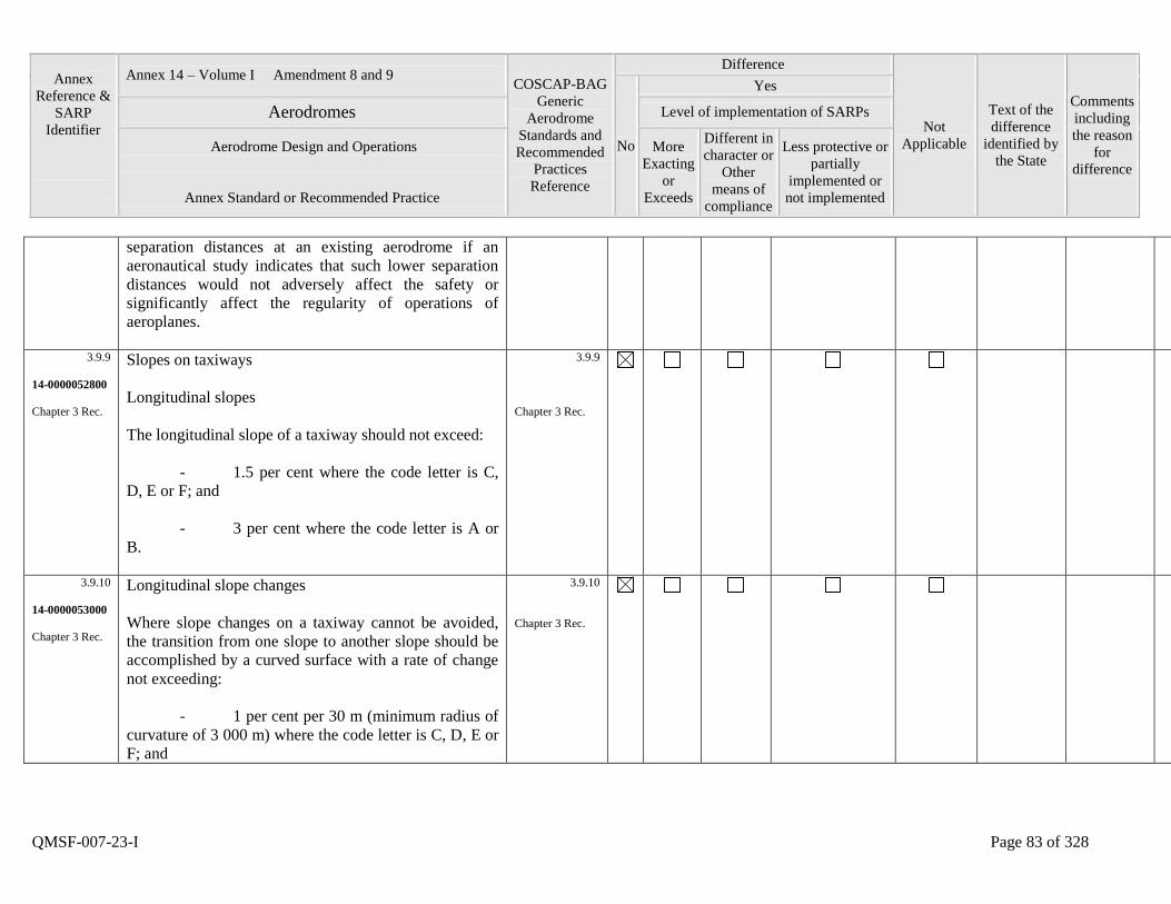
Annex
Reference &
SARP
Identifier
Annex 14 – Volume I Amendment 8 and 9 COSCAP-BAG
Generic
Aerodrome
Standards and
Recommended
Practices
Reference
Difference
Not
Applicable
Text of the
difference
identified by
the State
Comments
including
the reason
for
difference
No
Yes
Aerodromes Level of implementation of SARPs
Aerodrome Design and Operations
Annex Standard or Recommended Practice
More
Exacting
or
Exceeds
Different in
character or
Other
means of
compliance
Less protective or
partially
implemented or
not implemented
QMSF-007-23-I Page 83 of 328
separation distances at an existing aerodrome if an
aeronautical study indicates that such lower separation
distances would not adversely affect the safety or
significantly affect the regularity of operations of
aeroplanes.
3.9.9
14-0000052800
Chapter 3 Rec.
Slopes on taxiways
Longitudinal slopes
The longitudinal slope of a taxiway should not exceed:
- 1.5 per cent where the code letter is C,
D, E or F; and
- 3 per cent where the code letter is A or
B.
3.9.9
Chapter 3 Rec.
3.9.10
14-0000053000
Chapter 3 Rec.
Longitudinal slope changes
Where slope changes on a taxiway cannot be avoided,
the transition from one slope to another slope should be
accomplished by a curved surface with a rate of change
not exceeding:
- 1 per cent per 30 m (minimum radius of
curvature of 3 000 m) where the code letter is C, D, E or
F; and
3.9.10
Chapter 3 Rec.
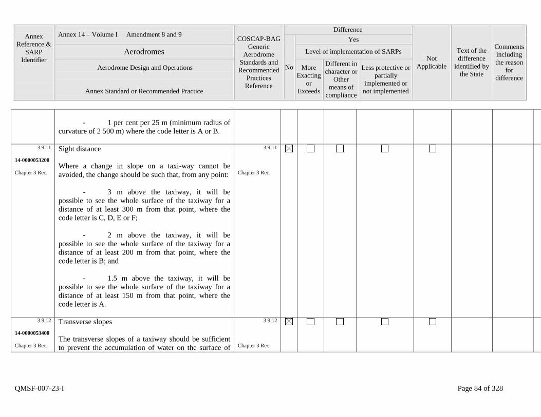
Annex
Reference &
SARP
Identifier
Annex 14 – Volume I Amendment 8 and 9 COSCAP-BAG
Generic
Aerodrome
Standards and
Recommended
Practices
Reference
Difference
Not
Applicable
Text of the
difference
identified by
the State
Comments
including
the reason
for
difference
No
Yes
Aerodromes Level of implementation of SARPs
Aerodrome Design and Operations
Annex Standard or Recommended Practice
More
Exacting
or
Exceeds
Different in
character or
Other
means of
compliance
Less protective or
partially
implemented or
not implemented
QMSF-007-23-I Page 84 of 328
- 1 per cent per 25 m (minimum radius of
curvature of 2 500 m) where the code letter is A or B.
3.9.11
14-0000053200
Chapter 3 Rec.
Sight distance
Where a change in slope on a taxi-way cannot be
avoided, the change should be such that, from any point:
- 3 m above the taxiway, it will be
possible to see the whole surface of the taxiway for a
distance of at least 300 m from that point, where the
code letter is C, D, E or F;
- 2 m above the taxiway, it will be
possible to see the whole surface of the taxiway for a
distance of at least 200 m from that point, where the
code letter is B; and
- 1.5 m above the taxiway, it will be
possible to see the whole surface of the taxiway for a
distance of at least 150 m from that point, where the
code letter is A.
3.9.11
Chapter 3 Rec.
3.9.12
14-0000053400
Chapter 3 Rec.
Transverse slopes
The transverse slopes of a taxiway should be sufficient
to prevent the accumulation of water on the surface of
3.9.12
Chapter 3 Rec.
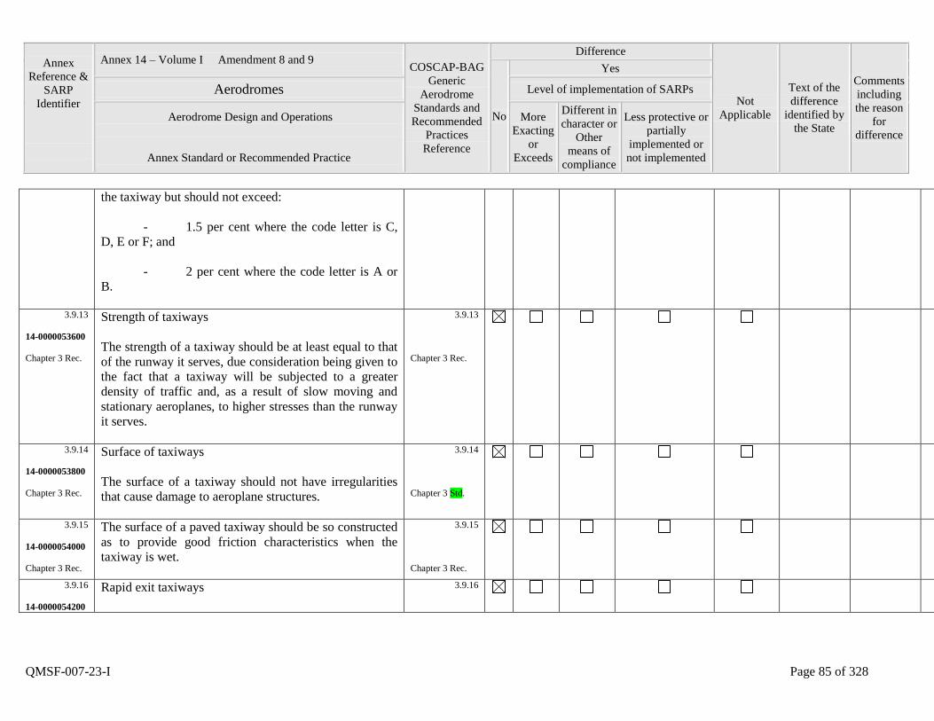
Annex
Reference &
SARP
Identifier
Annex 14 – Volume I Amendment 8 and 9 COSCAP-BAG
Generic
Aerodrome
Standards and
Recommended
Practices
Reference
Difference
Not
Applicable
Text of the
difference
identified by
the State
Comments
including
the reason
for
difference
No
Yes
Aerodromes Level of implementation of SARPs
Aerodrome Design and Operations
Annex Standard or Recommended Practice
More
Exacting
or
Exceeds
Different in
character or
Other
means of
compliance
Less protective or
partially
implemented or
not implemented
QMSF-007-23-I Page 85 of 328
the taxiway but should not exceed:
- 1.5 per cent where the code letter is C,
D, E or F; and
- 2 per cent where the code letter is A or
B.
3.9.13
14-0000053600
Chapter 3 Rec.
Strength of taxiways
The strength of a taxiway should be at least equal to that
of the runway it serves, due consideration being given to
the fact that a taxiway will be subjected to a greater
density of traffic and, as a result of slow moving and
stationary aeroplanes, to higher stresses than the runway
it serves.
3.9.13
Chapter 3 Rec.
3.9.14
14-0000053800
Chapter 3 Rec.
Surface of taxiways
The surface of a taxiway should not have irregularities
that cause damage to aeroplane structures.
3.9.14
Chapter 3 Std.
3.9.15
14-0000054000
Chapter 3 Rec.
The surface of a paved taxiway should be so constructed
as to provide good friction characteristics when the
taxiway is wet.
3.9.15
Chapter 3 Rec.
3.9.16
14-0000054200
Rapid exit taxiways
3.9.16
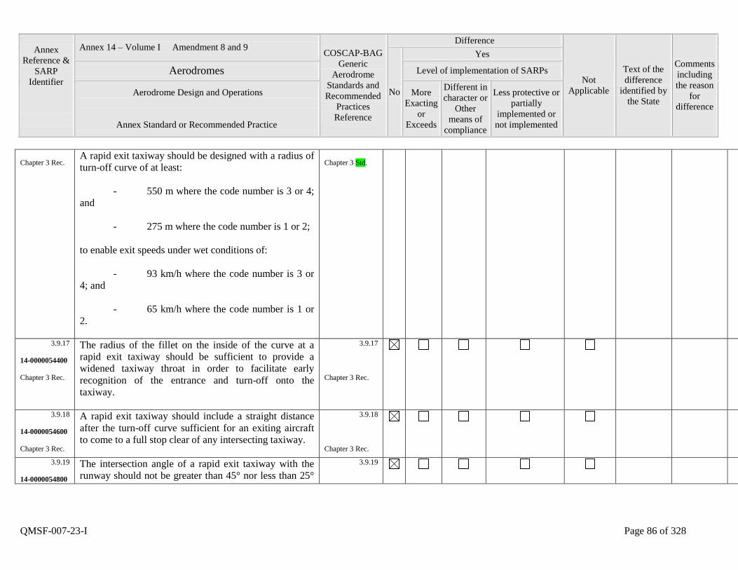
Annex
Reference &
SARP
Identifier
Annex 14 – Volume I Amendment 8 and 9 COSCAP-BAG
Generic
Aerodrome
Standards and
Recommended
Practices
Reference
Difference
Not
Applicable
Text of the
difference
identified by
the State
Comments
including
the reason
for
difference
No
Yes
Aerodromes Level of implementation of SARPs
Aerodrome Design and Operations
Annex Standard or Recommended Practice
More
Exacting
or
Exceeds
Different in
character or
Other
means of
compliance
Less protective or
partially
implemented or
not implemented
QMSF-007-23-I Page 86 of 328
Chapter 3 Rec. A rapid exit taxiway should be designed with a radius of
turn-off curve of at least:
- 550 m where the code number is 3 or 4;
and
- 275 m where the code number is 1 or 2;
to enable exit speeds under wet conditions of:
- 93 km/h where the code number is 3 or
4; and
- 65 km/h where the code number is 1 or
2.
Chapter 3 Std.
3.9.17
14-0000054400
Chapter 3 Rec.
The radius of the fillet on the inside of the curve at a
rapid exit taxiway should be sufficient to provide a
widened taxiway throat in order to facilitate early
recognition of the entrance and turn-off onto the
taxiway.
3.9.17
Chapter 3 Rec.
3.9.18
14-0000054600
Chapter 3 Rec.
A rapid exit taxiway should include a straight distance
after the turn-off curve sufficient for an exiting aircraft
to come to a full stop clear of any intersecting taxiway.
3.9.18
Chapter 3 Rec.
3.9.19
14-0000054800
The intersection angle of a rapid exit taxiway with the
runway should not be greater than 45° nor less than 25°
3.9.19
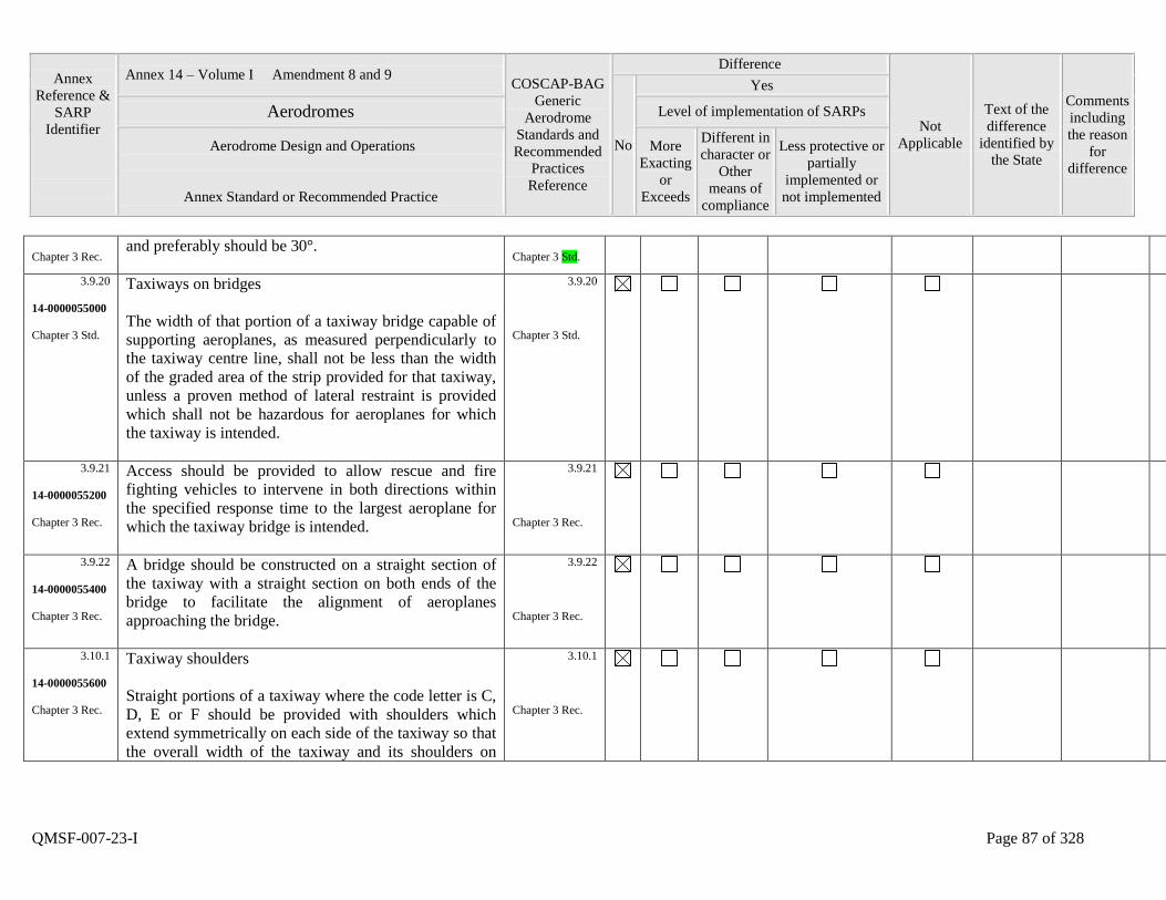
Annex
Reference &
SARP
Identifier
Annex 14 – Volume I Amendment 8 and 9 COSCAP-BAG
Generic
Aerodrome
Standards and
Recommended
Practices
Reference
Difference
Not
Applicable
Text of the
difference
identified by
the State
Comments
including
the reason
for
difference
No
Yes
Aerodromes Level of implementation of SARPs
Aerodrome Design and Operations
Annex Standard or Recommended Practice
More
Exacting
or
Exceeds
Different in
character or
Other
means of
compliance
Less protective or
partially
implemented or
not implemented
QMSF-007-23-I Page 87 of 328
Chapter 3 Rec. and preferably should be 30°.
Chapter 3 Std.
3.9.20
14-0000055000
Chapter 3 Std.
Taxiways on bridges
The width of that portion of a taxiway bridge capable of
supporting aeroplanes, as measured perpendicularly to
the taxiway centre line, shall not be less than the width
of the graded area of the strip provided for that taxiway,
unless a proven method of lateral restraint is provided
which shall not be hazardous for aeroplanes for which
the taxiway is intended.
3.9.20
Chapter 3 Std.
3.9.21
14-0000055200
Chapter 3 Rec.
Access should be provided to allow rescue and fire
fighting vehicles to intervene in both directions within
the specified response time to the largest aeroplane for
which the taxiway bridge is intended.
3.9.21
Chapter 3 Rec.
3.9.22
14-0000055400
Chapter 3 Rec.
A bridge should be constructed on a straight section of
the taxiway with a straight section on both ends of the
bridge to facilitate the alignment of aeroplanes
approaching the bridge.
3.9.22
Chapter 3 Rec.
3.10.1
14-0000055600
Chapter 3 Rec.
Taxiway shoulders
Straight portions of a taxiway where the code letter is C,
D, E or F should be provided with shoulders which
extend symmetrically on each side of the taxiway so that
the overall width of the taxiway and its shoulders on
3.10.1
Chapter 3 Rec.
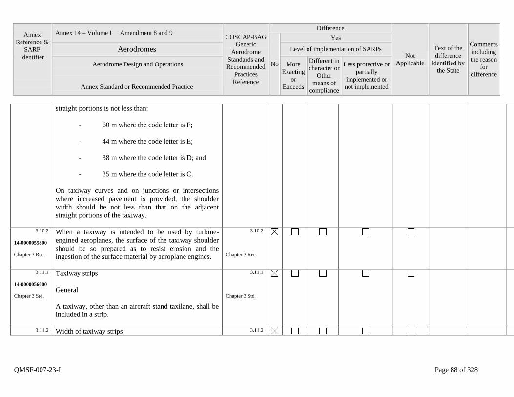
Annex
Reference &
SARP
Identifier
Annex 14 – Volume I Amendment 8 and 9 COSCAP-BAG
Generic
Aerodrome
Standards and
Recommended
Practices
Reference
Difference
Not
Applicable
Text of the
difference
identified by
the State
Comments
including
the reason
for
difference
No
Yes
Aerodromes Level of implementation of SARPs
Aerodrome Design and Operations
Annex Standard or Recommended Practice
More
Exacting
or
Exceeds
Different in
character or
Other
means of
compliance
Less protective or
partially
implemented or
not implemented
QMSF-007-23-I Page 88 of 328
straight portions is not less than:
- 60 m where the code letter is F;
- 44 m where the code letter is E;
- 38 m where the code letter is D; and
- 25 m where the code letter is C.
On taxiway curves and on junctions or intersections
where increased pavement is provided, the shoulder
width should be not less than that on the adjacent
straight portions of the taxiway.
3.10.2
14-0000055800
Chapter 3 Rec.
When a taxiway is intended to be used by turbine-
engined aeroplanes, the surface of the taxiway shoulder
should be so prepared as to resist erosion and the
ingestion of the surface material by aeroplane engines.
3.10.2
Chapter 3 Rec.
3.11.1
14-0000056000
Chapter 3 Std.
Taxiway strips
General
A taxiway, other than an aircraft stand taxilane, shall be
included in a strip.
3.11.1
Chapter 3 Std.
3.11.2 Width of taxiway strips 3.11.2
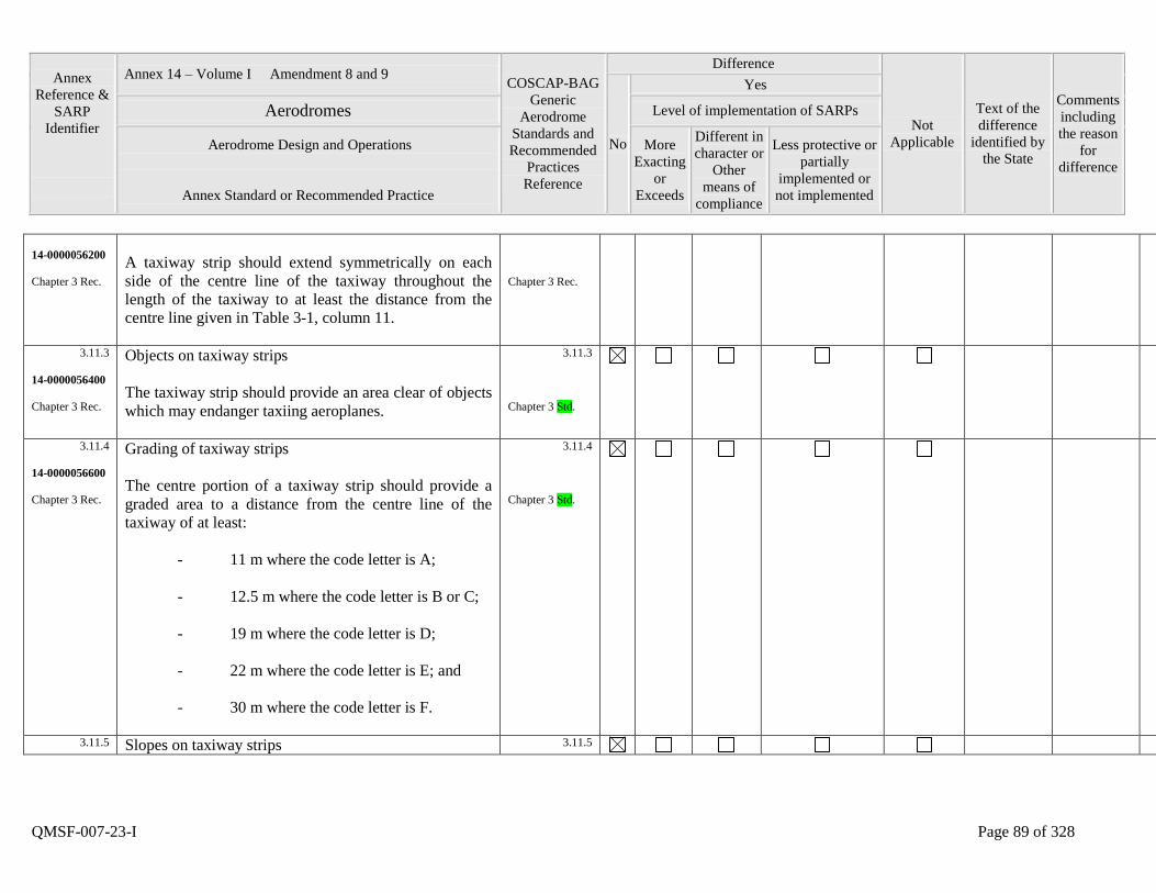
Annex
Reference &
SARP
Identifier
Annex 14 – Volume I Amendment 8 and 9 COSCAP-BAG
Generic
Aerodrome
Standards and
Recommended
Practices
Reference
Difference
Not
Applicable
Text of the
difference
identified by
the State
Comments
including
the reason
for
difference
No
Yes
Aerodromes Level of implementation of SARPs
Aerodrome Design and Operations
Annex Standard or Recommended Practice
More
Exacting
or
Exceeds
Different in
character or
Other
means of
compliance
Less protective or
partially
implemented or
not implemented
QMSF-007-23-I Page 89 of 328
14-0000056200
Chapter 3 Rec.
A taxiway strip should extend symmetrically on each
side of the centre line of the taxiway throughout the
length of the taxiway to at least the distance from the
centre line given in Table 3-1, column 11.
Chapter 3 Rec.
3.11.3
14-0000056400
Chapter 3 Rec.
Objects on taxiway strips
The taxiway strip should provide an area clear of objects
which may endanger taxiing aeroplanes.
3.11.3
Chapter 3 Std.
3.11.4
14-0000056600
Chapter 3 Rec.
Grading of taxiway strips
The centre portion of a taxiway strip should provide a
graded area to a distance from the centre line of the
taxiway of at least:
- 11 m where the code letter is A;
- 12.5 m where the code letter is B or C;
- 19 m where the code letter is D;
- 22 m where the code letter is E; and
- 30 m where the code letter is F.
3.11.4
Chapter 3 Std.
3.11.5 Slopes on taxiway strips 3.11.5
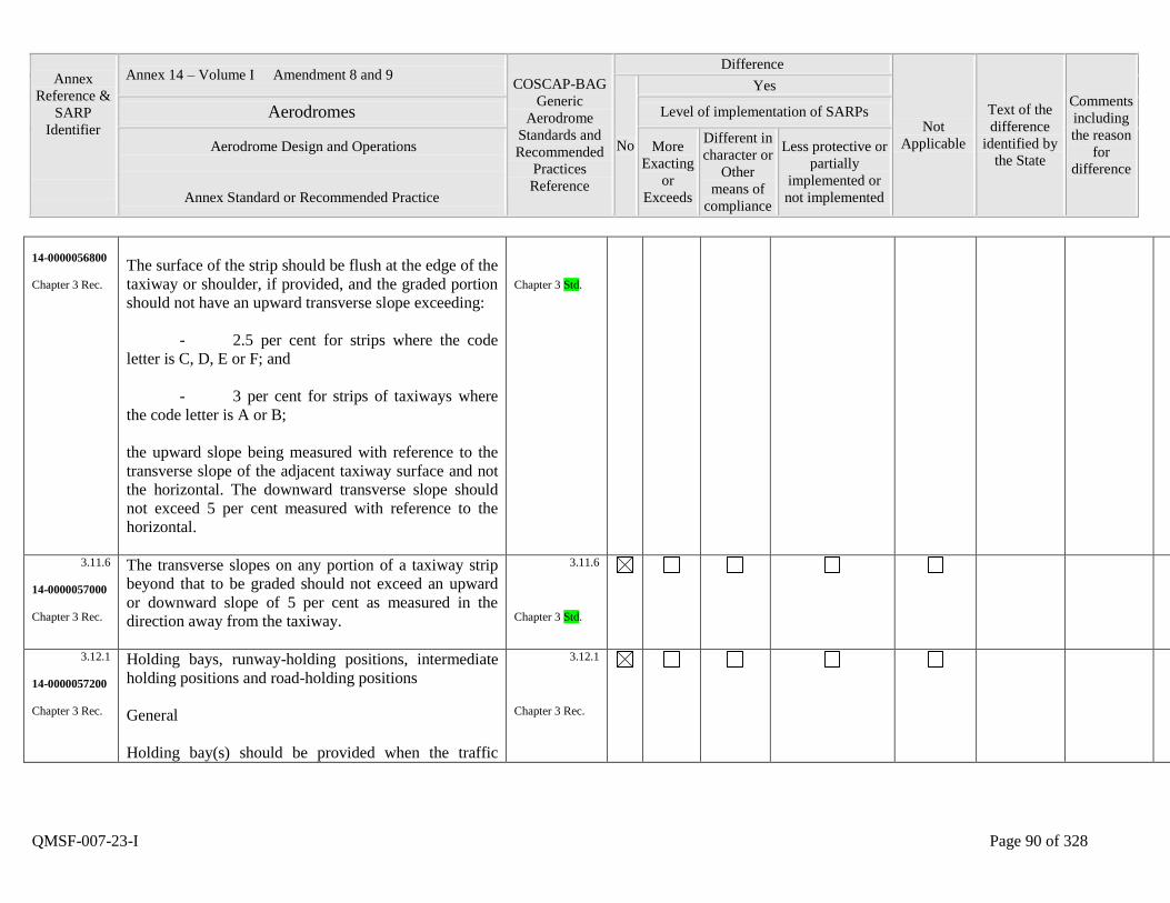
Annex
Reference &
SARP
Identifier
Annex 14 – Volume I Amendment 8 and 9 COSCAP-BAG
Generic
Aerodrome
Standards and
Recommended
Practices
Reference
Difference
Not
Applicable
Text of the
difference
identified by
the State
Comments
including
the reason
for
difference
No
Yes
Aerodromes Level of implementation of SARPs
Aerodrome Design and Operations
Annex Standard or Recommended Practice
More
Exacting
or
Exceeds
Different in
character or
Other
means of
compliance
Less protective or
partially
implemented or
not implemented
QMSF-007-23-I Page 90 of 328
14-0000056800
Chapter 3 Rec.
The surface of the strip should be flush at the edge of the
taxiway or shoulder, if provided, and the graded portion
should not have an upward transverse slope exceeding:
- 2.5 per cent for strips where the code
letter is C, D, E or F; and
- 3 per cent for strips of taxiways where
the code letter is A or B;
the upward slope being measured with reference to the
transverse slope of the adjacent taxiway surface and not
the horizontal. The downward transverse slope should
not exceed 5 per cent measured with reference to the
horizontal.
Chapter 3 Std.
3.11.6
14-0000057000
Chapter 3 Rec.
The transverse slopes on any portion of a taxiway strip
beyond that to be graded should not exceed an upward
or downward slope of 5 per cent as measured in the
direction away from the taxiway.
3.11.6
Chapter 3 Std.
3.12.1
14-0000057200
Chapter 3 Rec.
Holding bays, runway-holding positions, intermediate
holding positions and road-holding positions
General
Holding bay(s) should be provided when the traffic
3.12.1
Chapter 3 Rec.
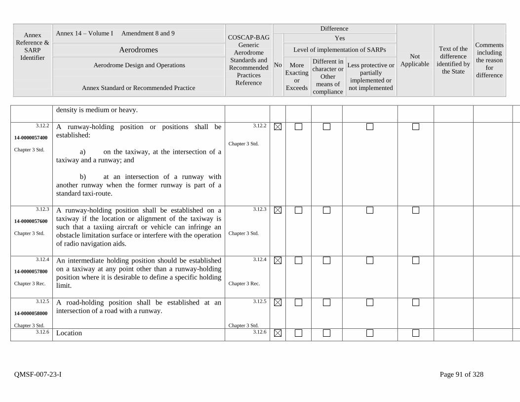
Annex
Reference &
SARP
Identifier
Annex 14 – Volume I Amendment 8 and 9 COSCAP-BAG
Generic
Aerodrome
Standards and
Recommended
Practices
Reference
Difference
Not
Applicable
Text of the
difference
identified by
the State
Comments
including
the reason
for
difference
No
Yes
Aerodromes Level of implementation of SARPs
Aerodrome Design and Operations
Annex Standard or Recommended Practice
More
Exacting
or
Exceeds
Different in
character or
Other
means of
compliance
Less protective or
partially
implemented or
not implemented
QMSF-007-23-I Page 91 of 328
density is medium or heavy.
3.12.2
14-0000057400
Chapter 3 Std.
A runway-holding position or positions shall be
established:
a) on the taxiway, at the intersection of a
taxiway and a runway; and
b) at an intersection of a runway with
another runway when the former runway is part of a
standard taxi-route.
3.12.2
Chapter 3 Std.
3.12.3
14-0000057600
Chapter 3 Std.
A runway-holding position shall be established on a
taxiway if the location or alignment of the taxiway is
such that a taxiing aircraft or vehicle can infringe an
obstacle limitation surface or interfere with the operation
of radio navigation aids.
3.12.3
Chapter 3 Std.
3.12.4
14-0000057800
Chapter 3 Rec.
An intermediate holding position should be established
on a taxiway at any point other than a runway-holding
position where it is desirable to define a specific holding
limit.
3.12.4
Chapter 3 Rec.
3.12.5
14-0000058000
Chapter 3 Std.
A road-holding position shall be established at an
intersection of a road with a runway.
3.12.5
Chapter 3 Std.
3.12.6
Location 3.12.6
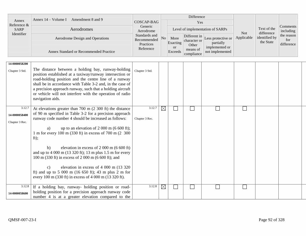
Annex
Reference &
SARP
Identifier
Annex 14 – Volume I Amendment 8 and 9 COSCAP-BAG
Generic
Aerodrome
Standards and
Recommended
Practices
Reference
Difference
Not
Applicable
Text of the
difference
identified by
the State
Comments
including
the reason
for
difference
No
Yes
Aerodromes Level of implementation of SARPs
Aerodrome Design and Operations
Annex Standard or Recommended Practice
More
Exacting
or
Exceeds
Different in
character or
Other
means of
compliance
Less protective or
partially
implemented or
not implemented
QMSF-007-23-I Page 92 of 328
14-0000058200
Chapter 3 Std.
The distance between a holding bay, runway-holding
position established at a taxiway/runway intersection or
road-holding position and the centre line of a runway
shall be in accordance with Table 3-2 and, in the case of
a precision approach runway, such that a holding aircraft
or vehicle will not interfere with the operation of radio
navigation aids.
Chapter 3 Std.
3.12.7
14-0000058400
Chapter 3 Rec.
At elevations greater than 700 m (2 300 ft) the distance
of 90 m specified in Table 3-2 for a precision approach
runway code number 4 should be increased as follows:
a) up to an elevation of 2 000 m (6 600 ft);
1 m for every 100 m (330 ft) in excess of 700 m (2 300
ft);
b) elevation in excess of 2 000 m (6 600 ft)
and up to 4 000 m (13 320 ft); 13 m plus 1.5 m for every
100 m (330 ft) in excess of 2 000 m (6 600 ft); and
c) elevation in excess of 4 000 m (13 320
ft) and up to 5 000 m (16 650 ft); 43 m plus 2 m for
every 100 m (330 ft) in excess of 4 000 m (13 320 ft).
3.12.7
Chapter 3 Rec.
3.12.8
14-0000058600
If a holding bay, runway- holding position or road-
holding position for a precision approach runway code
number 4 is at a greater elevation compared to the
3.12.8
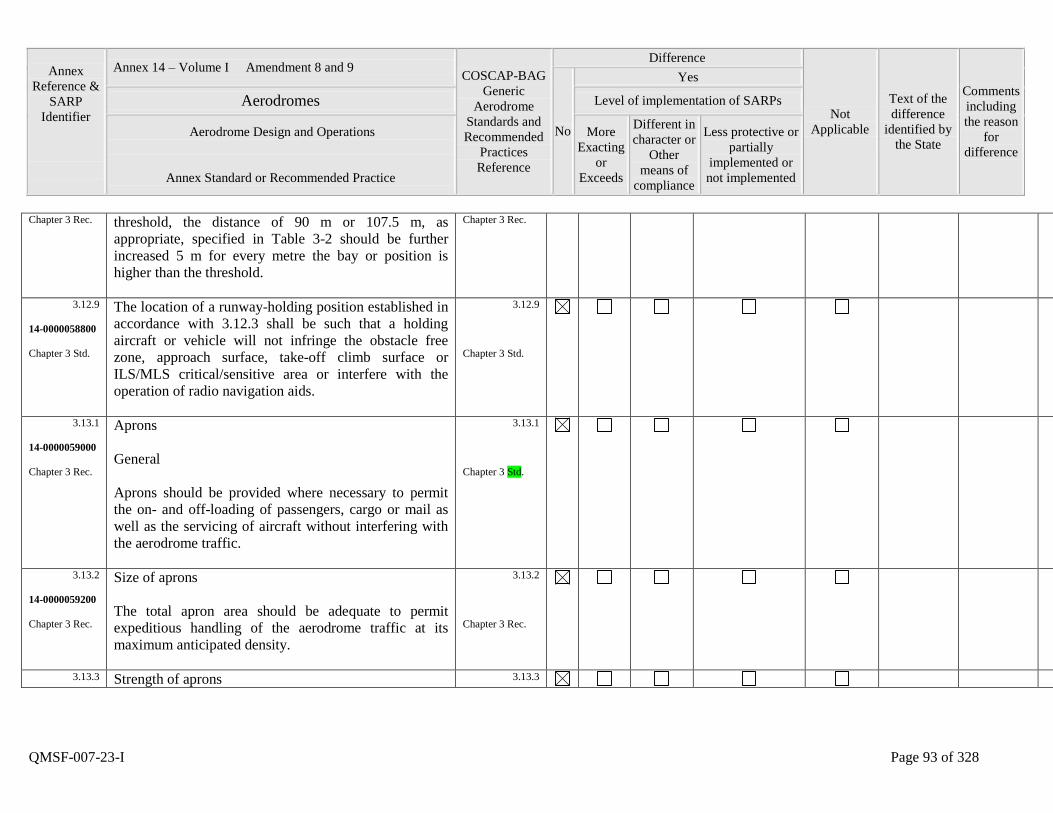
Annex
Reference &
SARP
Identifier
Annex 14 – Volume I Amendment 8 and 9 COSCAP-BAG
Generic
Aerodrome
Standards and
Recommended
Practices
Reference
Difference
Not
Applicable
Text of the
difference
identified by
the State
Comments
including
the reason
for
difference
No
Yes
Aerodromes Level of implementation of SARPs
Aerodrome Design and Operations
Annex Standard or Recommended Practice
More
Exacting
or
Exceeds
Different in
character or
Other
means of
compliance
Less protective or
partially
implemented or
not implemented
QMSF-007-23-I Page 93 of 328
Chapter 3 Rec. threshold, the distance of 90 m or 107.5 m, as
appropriate, specified in Table 3-2 should be further
increased 5 m for every metre the bay or position is
higher than the threshold.
Chapter 3 Rec.
3.12.9
14-0000058800
Chapter 3 Std.
The location of a runway-holding position established in
accordance with 3.12.3 shall be such that a holding
aircraft or vehicle will not infringe the obstacle free
zone, approach surface, take-off climb surface or
ILS/MLS critical/sensitive area or interfere with the
operation of radio navigation aids.
3.12.9
Chapter 3 Std.
3.13.1
14-0000059000
Chapter 3 Rec.
Aprons
General
Aprons should be provided where necessary to permit
the on- and off-loading of passengers, cargo or mail as
well as the servicing of aircraft without interfering with
the aerodrome traffic.
3.13.1
Chapter 3 Std.
3.13.2
14-0000059200
Chapter 3 Rec.
Size of aprons
The total apron area should be adequate to permit
expeditious handling of the aerodrome traffic at its
maximum anticipated density.
3.13.2
Chapter 3 Rec.
3.13.3 Strength of aprons 3.13.3
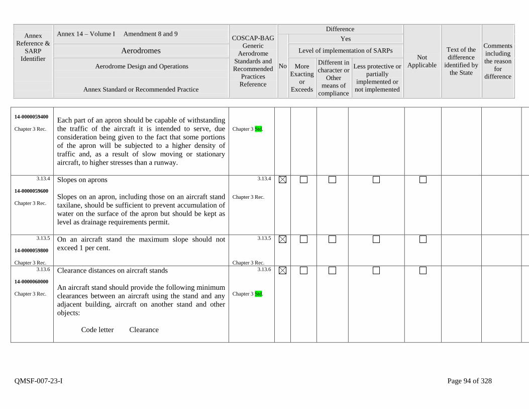
Annex
Reference &
SARP
Identifier
Annex 14 – Volume I Amendment 8 and 9 COSCAP-BAG
Generic
Aerodrome
Standards and
Recommended
Practices
Reference
Difference
Not
Applicable
Text of the
difference
identified by
the State
Comments
including
the reason
for
difference
No
Yes
Aerodromes Level of implementation of SARPs
Aerodrome Design and Operations
Annex Standard or Recommended Practice
More
Exacting
or
Exceeds
Different in
character or
Other
means of
compliance
Less protective or
partially
implemented or
not implemented
QMSF-007-23-I Page 94 of 328
14-0000059400
Chapter 3 Rec.
Each part of an apron should be capable of withstanding
the traffic of the aircraft it is intended to serve, due
consideration being given to the fact that some portions
of the apron will be subjected to a higher density of
traffic and, as a result of slow moving or stationary
aircraft, to higher stresses than a runway.
Chapter 3 Std.
3.13.4
14-0000059600
Chapter 3 Rec.
Slopes on aprons
Slopes on an apron, including those on an aircraft stand
taxilane, should be sufficient to prevent accumulation of
water on the surface of the apron but should be kept as
level as drainage requirements permit.
3.13.4
Chapter 3 Rec.
3.13.5
14-0000059800
Chapter 3 Rec.
On an aircraft stand the maximum slope should not
exceed 1 per cent.
3.13.5
Chapter 3 Rec.
3.13.6
14-0000060000
Chapter 3 Rec.
Clearance distances on aircraft stands
An aircraft stand should provide the following minimum
clearances between an aircraft using the stand and any
adjacent building, aircraft on another stand and other
objects:
Code letter Clearance
3.13.6
Chapter 3 Std.
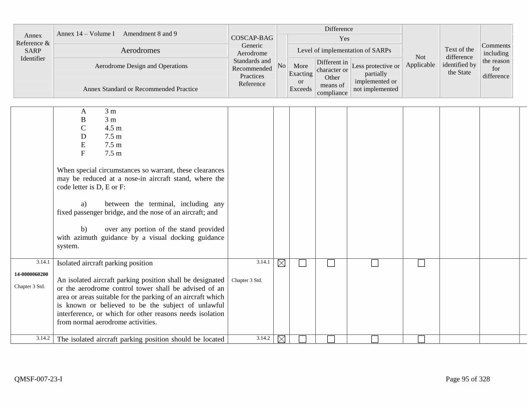
Annex
Reference &
SARP
Identifier
Annex 14 – Volume I Amendment 8 and 9 COSCAP-BAG
Generic
Aerodrome
Standards and
Recommended
Practices
Reference
Difference
Not
Applicable
Text of the
difference
identified by
the State
Comments
including
the reason
for
difference
No
Yes
Aerodromes Level of implementation of SARPs
Aerodrome Design and Operations
Annex Standard or Recommended Practice
More
Exacting
or
Exceeds
Different in
character or
Other
means of
compliance
Less protective or
partially
implemented or
not implemented
QMSF-007-23-I Page 95 of 328
A 3 m
B 3 m
C 4.5 m
D 7.5 m
E 7.5 m
F 7.5 m
When special circumstances so warrant, these clearances
may be reduced at a nose-in aircraft stand, where the
code letter is D, E or F:
a) between the terminal, including any
fixed passenger bridge, and the nose of an aircraft; and
b) over any portion of the stand provided
with azimuth guidance by a visual docking guidance
system.
3.14.1
14-0000060200
Chapter 3 Std.
Isolated aircraft parking position
An isolated aircraft parking position shall be designated
or the aerodrome control tower shall be advised of an
area or areas suitable for the parking of an aircraft which
is known or believed to be the subject of unlawful
interference, or which for other reasons needs isolation
from normal aerodrome activities.
3.14.1
Chapter 3 Std.
3.14.2 The isolated aircraft parking position should be located 3.14.2
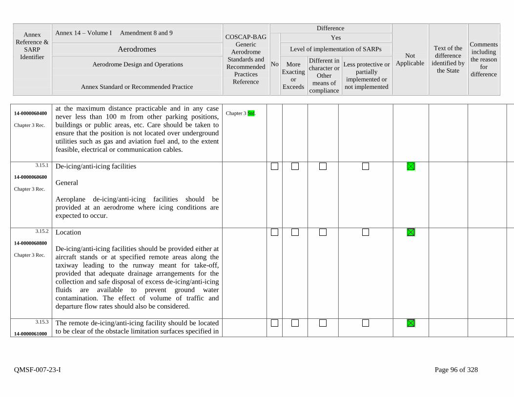
Annex
Reference &
SARP
Identifier
Annex 14 – Volume I Amendment 8 and 9 COSCAP-BAG
Generic
Aerodrome
Standards and
Recommended
Practices
Reference
Difference
Not
Applicable
Text of the
difference
identified by
the State
Comments
including
the reason
for
difference
No
Yes
Aerodromes Level of implementation of SARPs
Aerodrome Design and Operations
Annex Standard or Recommended Practice
More
Exacting
or
Exceeds
Different in
character or
Other
means of
compliance
Less protective or
partially
implemented or
not implemented
QMSF-007-23-I Page 96 of 328
14-0000060400
Chapter 3 Rec.
at the maximum distance practicable and in any case
never less than 100 m from other parking positions,
buildings or public areas, etc. Care should be taken to
ensure that the position is not located over underground
utilities such as gas and aviation fuel and, to the extent
feasible, electrical or communication cables.
Chapter 3 Std.
3.15.1
14-0000060600
Chapter 3 Rec.
De-icing/anti-icing facilities
General
Aeroplane de-icing/anti-icing facilities should be
provided at an aerodrome where icing conditions are
expected to occur.
3.15.2
14-0000060800
Chapter 3 Rec.
Location
De-icing/anti-icing facilities should be provided either at
aircraft stands or at specified remote areas along the
taxiway leading to the runway meant for take-off,
provided that adequate drainage arrangements for the
collection and safe disposal of excess de-icing/anti-icing
fluids are available to prevent ground water
contamination. The effect of volume of traffic and
departure flow rates should also be considered.
3.15.3
14-0000061000
The remote de-icing/anti-icing facility should be located
to be clear of the obstacle limitation surfaces specified in
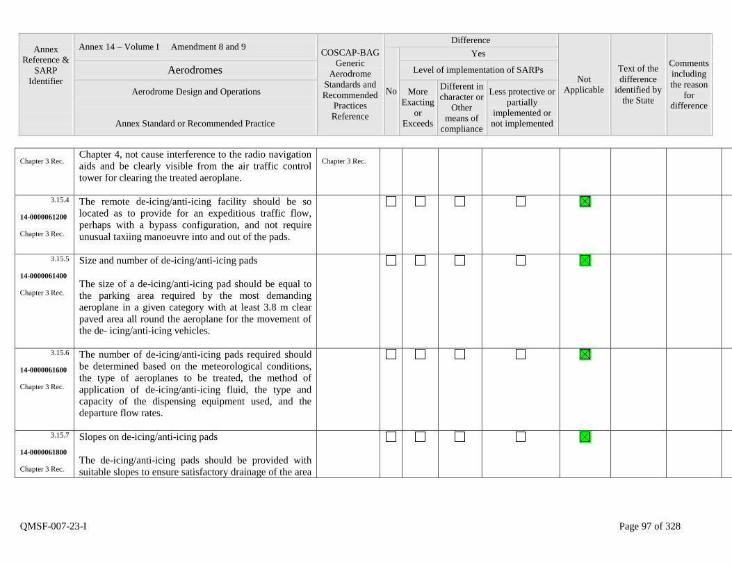
Annex
Reference &
SARP
Identifier
Annex 14 – Volume I Amendment 8 and 9 COSCAP-BAG
Generic
Aerodrome
Standards and
Recommended
Practices
Reference
Difference
Not
Applicable
Text of the
difference
identified by
the State
Comments
including
the reason
for
difference
No
Yes
Aerodromes Level of implementation of SARPs
Aerodrome Design and Operations
Annex Standard or Recommended Practice
More
Exacting
or
Exceeds
Different in
character or
Other
means of
compliance
Less protective or
partially
implemented or
not implemented
QMSF-007-23-I Page 97 of 328
Chapter 3 Rec. Chapter 4, not cause interference to the radio navigation
aids and be clearly visible from the air traffic control
tower for clearing the treated aeroplane.
Chapter 3 Rec.
3.15.4
14-0000061200
Chapter 3 Rec.
The remote de-icing/anti-icing facility should be so
located as to provide for an expeditious traffic flow,
perhaps with a bypass configuration, and not require
unusual taxiing manoeuvre into and out of the pads.
3.15.5
14-0000061400
Chapter 3 Rec.
Size and number of de-icing/anti-icing pads
The size of a de-icing/anti-icing pad should be equal to
the parking area required by the most demanding
aeroplane in a given category with at least 3.8 m clear
paved area all round the aeroplane for the movement of
the de- icing/anti-icing vehicles.
3.15.6
14-0000061600
Chapter 3 Rec.
The number of de-icing/anti-icing pads required should
be determined based on the meteorological conditions,
the type of aeroplanes to be treated, the method of
application of de-icing/anti-icing fluid, the type and
capacity of the dispensing equipment used, and the
departure flow rates.
3.15.7
14-0000061800
Chapter 3 Rec.
Slopes on de-icing/anti-icing pads
The de-icing/anti-icing pads should be provided with
suitable slopes to ensure satisfactory drainage of the area
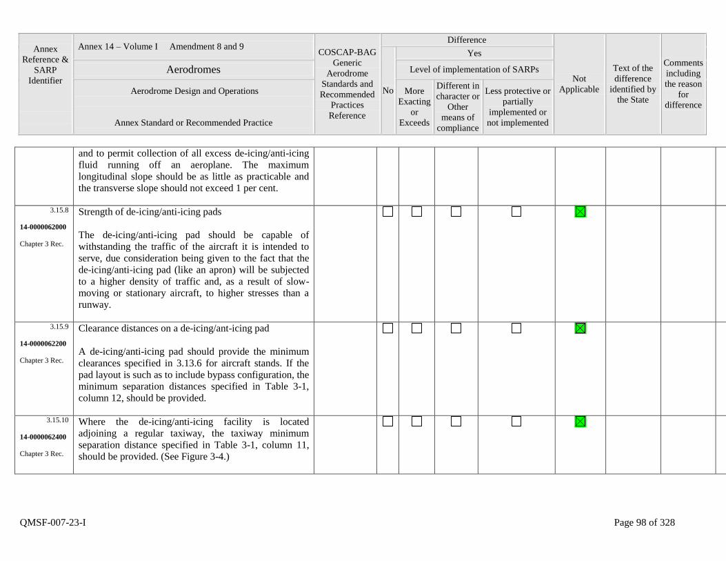
Annex
Reference &
SARP
Identifier
Annex 14 – Volume I Amendment 8 and 9 COSCAP-BAG
Generic
Aerodrome
Standards and
Recommended
Practices
Reference
Difference
Not
Applicable
Text of the
difference
identified by
the State
Comments
including
the reason
for
difference
No
Yes
Aerodromes Level of implementation of SARPs
Aerodrome Design and Operations
Annex Standard or Recommended Practice
More
Exacting
or
Exceeds
Different in
character or
Other
means of
compliance
Less protective or
partially
implemented or
not implemented
QMSF-007-23-I Page 98 of 328
and to permit collection of all excess de-icing/anti-icing
fluid running off an aeroplane. The maximum
longitudinal slope should be as little as practicable and
the transverse slope should not exceed 1 per cent.
3.15.8
14-0000062000
Chapter 3 Rec.
Strength of de-icing/anti-icing pads
The de-icing/anti-icing pad should be capable of
withstanding the traffic of the aircraft it is intended to
serve, due consideration being given to the fact that the
de-icing/anti-icing pad (like an apron) will be subjected
to a higher density of traffic and, as a result of slow-
moving or stationary aircraft, to higher stresses than a
runway.
3.15.9
14-0000062200
Chapter 3 Rec.
Clearance distances on a de-icing/ant-icing pad
A de-icing/anti-icing pad should provide the minimum
clearances specified in 3.13.6 for aircraft stands. If the
pad layout is such as to include bypass configuration, the
minimum separation distances specified in Table 3-1,
column 12, should be provided.
3.15.10
14-0000062400
Chapter 3 Rec.
Where the de-icing/anti-icing facility is located
adjoining a regular taxiway, the taxiway minimum
separation distance specified in Table 3-1, column 11,
should be provided. (See Figure 3-4.)
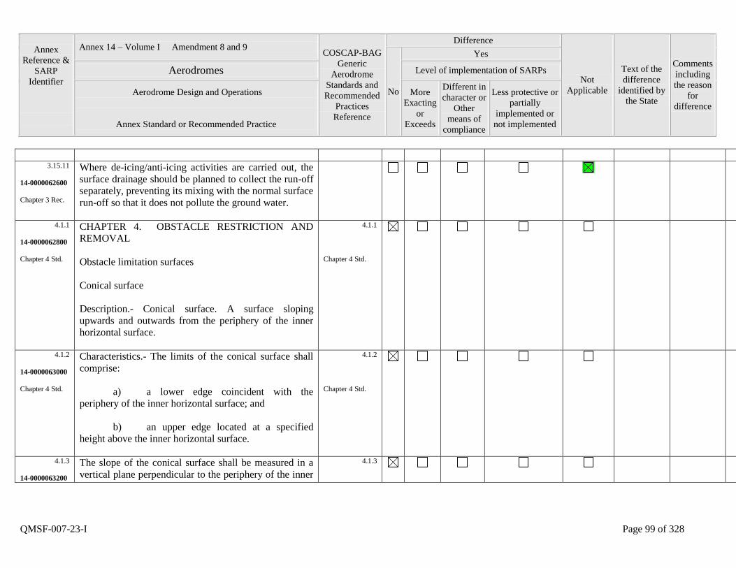
Annex
Reference &
SARP
Identifier
Annex 14 – Volume I Amendment 8 and 9 COSCAP-BAG
Generic
Aerodrome
Standards and
Recommended
Practices
Reference
Difference
Not
Applicable
Text of the
difference
identified by
the State
Comments
including
the reason
for
difference
No
Yes
Aerodromes Level of implementation of SARPs
Aerodrome Design and Operations
Annex Standard or Recommended Practice
More
Exacting
or
Exceeds
Different in
character or
Other
means of
compliance
Less protective or
partially
implemented or
not implemented
QMSF-007-23-I Page 99 of 328
3.15.11
14-0000062600
Chapter 3 Rec.
Where de-icing/anti-icing activities are carried out, the
surface drainage should be planned to collect the run-off
separately, preventing its mixing with the normal surface
run-off so that it does not pollute the ground water.
4.1.1
14-0000062800
Chapter 4 Std.
CHAPTER 4. OBSTACLE RESTRICTION AND
REMOVAL
Obstacle limitation surfaces
Conical surface
Description.- Conical surface. A surface sloping
upwards and outwards from the periphery of the inner
horizontal surface.
4.1.1
Chapter 4 Std.
4.1.2
14-0000063000
Chapter 4 Std.
Characteristics.- The limits of the conical surface shall
comprise:
a) a lower edge coincident with the
periphery of the inner horizontal surface; and
b) an upper edge located at a specified
height above the inner horizontal surface.
4.1.2
Chapter 4 Std.
4.1.3
14-0000063200
The slope of the conical surface shall be measured in a
vertical plane perpendicular to the periphery of the inner
4.1.3

Annex
Reference &
SARP
Identifier
Annex 14 – Volume I Amendment 8 and 9 COSCAP-BAG
Generic
Aerodrome
Standards and
Recommended
Practices
Reference
Difference
Not
Applicable
Text of the
difference
identified by
the State
Comments
including
the reason
for
difference
No
Yes
Aerodromes Level of implementation of SARPs
Aerodrome Design and Operations
Annex Standard or Recommended Practice
More
Exacting
or
Exceeds
Different in
character or
Other
means of
compliance
Less protective or
partially
implemented or
not implemented
QMSF-007-23-I Page 100 of 328
Chapter 4 Std. horizontal surface.
Chapter 4 Std.
4.1.4
14-0000063400
Chapter 4 Std.
Inner horizontal surface
Description.- Inner horizontal surface. A surface located
in a horizontal plane above an aerodrome and its
environs.
4.1.4
Chapter 4 Std.
4.1.5
14-0000063600
Chapter 4 Std.
Characteristics.- The radius or outer limits of the inner
horizontal surface shall be measured from a reference
point or points established for such purpose.
4.1.5
Chapter 4 Std.
4.1.6
14-0000063800
Chapter 4 Std.
The height of the inner horizontal surface shall be
measured above an elevation datum established for such
purpose.
4.1.6
Chapter 4 Std.
4.1.7
14-0000064000
Chapter 4 Std.
Approach surface
Description.- Approach surface. An inclined plane or
combination of planes preceding the threshold.
4.1.7
Chapter 4 Std.
4.1.8
14-0000064200
Chapter 4 Std.
Characteristics.- The limits of the approach surface shall
comprise:
a) an inner edge of specified length,
horizontal and perpendicular to the extended centre line
of the runway and located at a specified distance before
the threshold;
4.1.8
Chapter 4 Std.
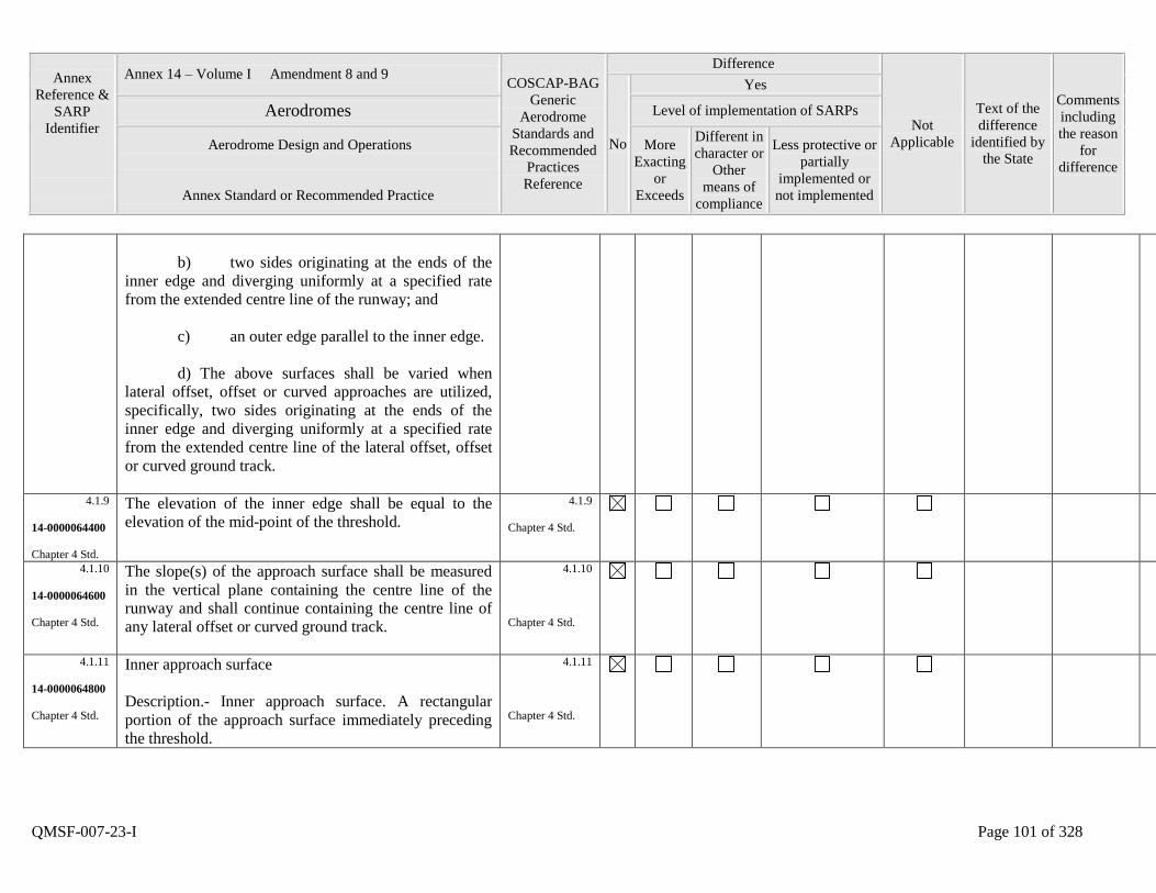
Annex
Reference &
SARP
Identifier
Annex 14 – Volume I Amendment 8 and 9 COSCAP-BAG
Generic
Aerodrome
Standards and
Recommended
Practices
Reference
Difference
Not
Applicable
Text of the
difference
identified by
the State
Comments
including
the reason
for
difference
No
Yes
Aerodromes Level of implementation of SARPs
Aerodrome Design and Operations
Annex Standard or Recommended Practice
More
Exacting
or
Exceeds
Different in
character or
Other
means of
compliance
Less protective or
partially
implemented or
not implemented
QMSF-007-23-I Page 101 of 328
b) two sides originating at the ends of the
inner edge and diverging uniformly at a specified rate
from the extended centre line of the runway; and
c) an outer edge parallel to the inner edge.
d) The above surfaces shall be varied when
lateral offset, offset or curved approaches are utilized,
specifically, two sides originating at the ends of the
inner edge and diverging uniformly at a specified rate
from the extended centre line of the lateral offset, offset
or curved ground track.
4.1.9
14-0000064400
Chapter 4 Std.
The elevation of the inner edge shall be equal to the
elevation of the mid-point of the threshold.
4.1.9
Chapter 4 Std.
4.1.10
14-0000064600
Chapter 4 Std.
The slope(s) of the approach surface shall be measured
in the vertical plane containing the centre line of the
runway and shall continue containing the centre line of
any lateral offset or curved ground track.
4.1.10
Chapter 4 Std.
4.1.11
14-0000064800
Chapter 4 Std.
Inner approach surface
Description.- Inner approach surface. A rectangular
portion of the approach surface immediately preceding
the threshold.
4.1.11
Chapter 4 Std.
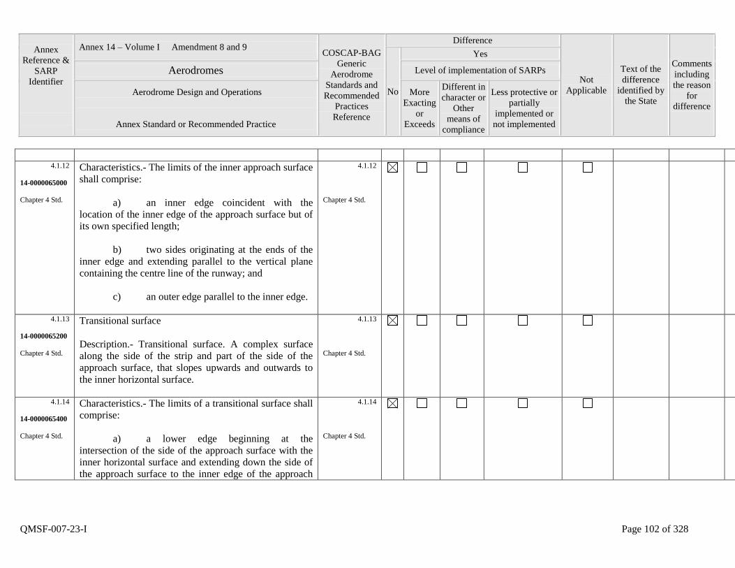
Annex
Reference &
SARP
Identifier
Annex 14 – Volume I Amendment 8 and 9 COSCAP-BAG
Generic
Aerodrome
Standards and
Recommended
Practices
Reference
Difference
Not
Applicable
Text of the
difference
identified by
the State
Comments
including
the reason
for
difference
No
Yes
Aerodromes Level of implementation of SARPs
Aerodrome Design and Operations
Annex Standard or Recommended Practice
More
Exacting
or
Exceeds
Different in
character or
Other
means of
compliance
Less protective or
partially
implemented or
not implemented
QMSF-007-23-I Page 102 of 328
4.1.12
14-0000065000
Chapter 4 Std.
Characteristics.- The limits of the inner approach surface
shall comprise:
a) an inner edge coincident with the
location of the inner edge of the approach surface but of
its own specified length;
b) two sides originating at the ends of the
inner edge and extending parallel to the vertical plane
containing the centre line of the runway; and
c) an outer edge parallel to the inner edge.
4.1.12
Chapter 4 Std.
4.1.13
14-0000065200
Chapter 4 Std.
Transitional surface
Description.- Transitional surface. A complex surface
along the side of the strip and part of the side of the
approach surface, that slopes upwards and outwards to
the inner horizontal surface.
4.1.13
Chapter 4 Std.
4.1.14
14-0000065400
Chapter 4 Std.
Characteristics.- The limits of a transitional surface shall
comprise:
a) a lower edge beginning at the
intersection of the side of the approach surface with the
inner horizontal surface and extending down the side of
the approach surface to the inner edge of the approach
4.1.14
Chapter 4 Std.
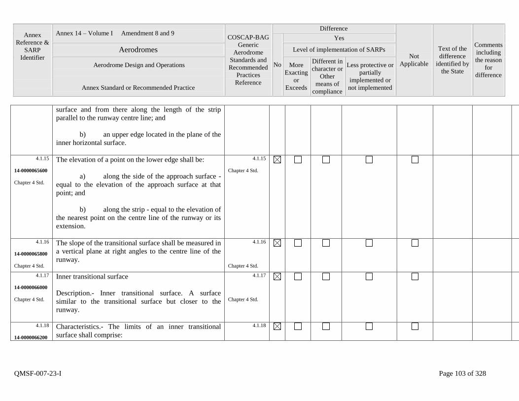
Annex
Reference &
SARP
Identifier
Annex 14 – Volume I Amendment 8 and 9 COSCAP-BAG
Generic
Aerodrome
Standards and
Recommended
Practices
Reference
Difference
Not
Applicable
Text of the
difference
identified by
the State
Comments
including
the reason
for
difference
No
Yes
Aerodromes Level of implementation of SARPs
Aerodrome Design and Operations
Annex Standard or Recommended Practice
More
Exacting
or
Exceeds
Different in
character or
Other
means of
compliance
Less protective or
partially
implemented or
not implemented
QMSF-007-23-I Page 103 of 328
surface and from there along the length of the strip
parallel to the runway centre line; and
b) an upper edge located in the plane of the
inner horizontal surface.
4.1.15
14-0000065600
Chapter 4 Std.
The elevation of a point on the lower edge shall be:
a) along the side of the approach surface -
equal to the elevation of the approach surface at that
point; and
b) along the strip - equal to the elevation of
the nearest point on the centre line of the runway or its
extension.
4.1.15
Chapter 4 Std.
4.1.16
14-0000065800
Chapter 4 Std.
The slope of the transitional surface shall be measured in
a vertical plane at right angles to the centre line of the
runway.
4.1.16
Chapter 4 Std.
4.1.17
14-0000066000
Chapter 4 Std.
Inner transitional surface
Description.- Inner transitional surface. A surface
similar to the transitional surface but closer to the
runway.
4.1.17
Chapter 4 Std.
4.1.18
14-0000066200
Characteristics.- The limits of an inner transitional
surface shall comprise:
4.1.18
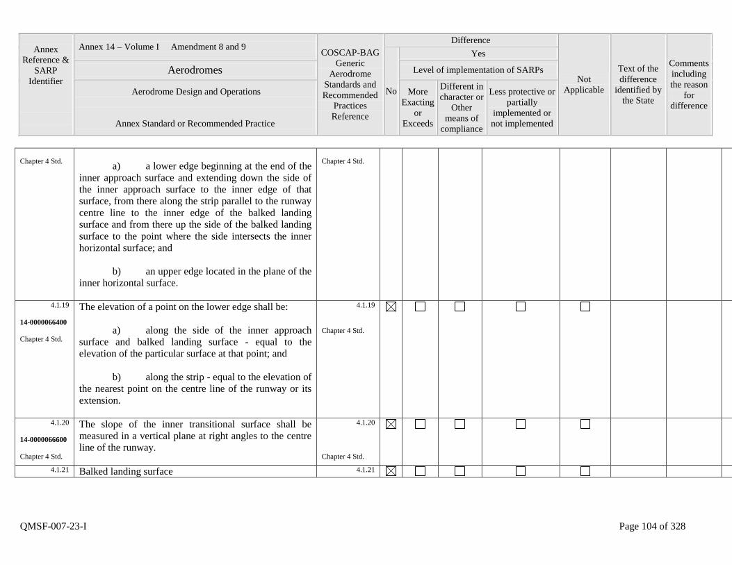
Annex
Reference &
SARP
Identifier
Annex 14 – Volume I Amendment 8 and 9 COSCAP-BAG
Generic
Aerodrome
Standards and
Recommended
Practices
Reference
Difference
Not
Applicable
Text of the
difference
identified by
the State
Comments
including
the reason
for
difference
No
Yes
Aerodromes Level of implementation of SARPs
Aerodrome Design and Operations
Annex Standard or Recommended Practice
More
Exacting
or
Exceeds
Different in
character or
Other
means of
compliance
Less protective or
partially
implemented or
not implemented
QMSF-007-23-I Page 104 of 328
Chapter 4 Std.
a) a lower edge beginning at the end of the
inner approach surface and extending down the side of
the inner approach surface to the inner edge of that
surface, from there along the strip parallel to the runway
centre line to the inner edge of the balked landing
surface and from there up the side of the balked landing
surface to the point where the side intersects the inner
horizontal surface; and
b) an upper edge located in the plane of the
inner horizontal surface.
Chapter 4 Std.
4.1.19
14-0000066400
Chapter 4 Std.
The elevation of a point on the lower edge shall be:
a) along the side of the inner approach
surface and balked landing surface - equal to the
elevation of the particular surface at that point; and
b) along the strip - equal to the elevation of
the nearest point on the centre line of the runway or its
extension.
4.1.19
Chapter 4 Std.
4.1.20
14-0000066600
Chapter 4 Std.
The slope of the inner transitional surface shall be
measured in a vertical plane at right angles to the centre
line of the runway.
4.1.20
Chapter 4 Std.
4.1.21 Balked landing surface 4.1.21

Annex
Reference &
SARP
Identifier
Annex 14 – Volume I Amendment 8 and 9 COSCAP-BAG
Generic
Aerodrome
Standards and
Recommended
Practices
Reference
Difference
Not
Applicable
Text of the
difference
identified by
the State
Comments
including
the reason
for
difference
No
Yes
Aerodromes Level of implementation of SARPs
Aerodrome Design and Operations
Annex Standard or Recommended Practice
More
Exacting
or
Exceeds
Different in
character or
Other
means of
compliance
Less protective or
partially
implemented or
not implemented
QMSF-007-23-I Page 105 of 328
14-0000066800
Chapter 4 Std.
Description.- Balked landing surface. An inclined plane
located at a specified distance after the threshold,
extending between the inner transitional surface.
Chapter 4 Std.
4.1.22
14-0000067000
Chapter 4 Std.
Characteristics.- The limits of the balked landing surface
shall comprise:
a) an inner edge horizontal and
perpendicular to the centre line of the runway and
located at a specified distance after the threshold;
b) two sides originating at the ends of the
inner edge and diverging uniformly at a specified rate
from the vertical plane containing the centre line of the
runway; and
c) an outer edge parallel to the inner edge
and located in the plane of the inner horizontal surface.
4.1.22
Chapter 4 Std.
4.1.23
14-0000067200
Chapter 4 Std.
The elevation of the inner edge shall be equal to the
elevation of the runway centre line at the location of the
inner edge.
4.1.23
Chapter 4 Std.
4.1.24
14-0000067400
Chapter 4 Std.
The slope of the balked landing surface shall be
measured in the vertical plane containing the centre line
of the runway.
4.1.24
Chapter 4 Std.
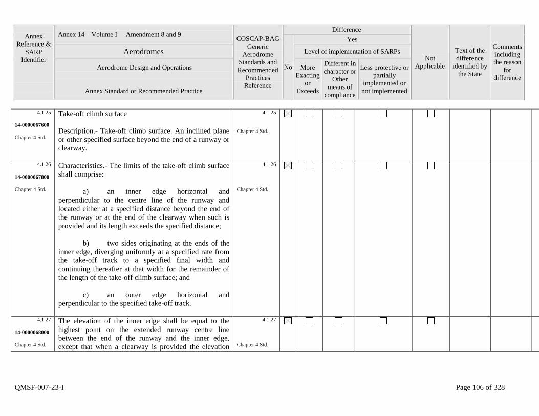
Annex
Reference &
SARP
Identifier
Annex 14 – Volume I Amendment 8 and 9 COSCAP-BAG
Generic
Aerodrome
Standards and
Recommended
Practices
Reference
Difference
Not
Applicable
Text of the
difference
identified by
the State
Comments
including
the reason
for
difference
No
Yes
Aerodromes Level of implementation of SARPs
Aerodrome Design and Operations
Annex Standard or Recommended Practice
More
Exacting
or
Exceeds
Different in
character or
Other
means of
compliance
Less protective or
partially
implemented or
not implemented
QMSF-007-23-I Page 106 of 328
4.1.25
14-0000067600
Chapter 4 Std.
Take-off climb surface
Description.- Take-off climb surface. An inclined plane
or other specified surface beyond the end of a runway or
clearway.
4.1.25
Chapter 4 Std.
4.1.26
14-0000067800
Chapter 4 Std.
Characteristics.- The limits of the take-off climb surface
shall comprise:
a) an inner edge horizontal and
perpendicular to the centre line of the runway and
located either at a specified distance beyond the end of
the runway or at the end of the clearway when such is
provided and its length exceeds the specified distance;
b) two sides originating at the ends of the
inner edge, diverging uniformly at a specified rate from
the take-off track to a specified final width and
continuing thereafter at that width for the remainder of
the length of the take-off climb surface; and
c) an outer edge horizontal and
perpendicular to the specified take-off track.
4.1.26
Chapter 4 Std.
4.1.27
14-0000068000
Chapter 4 Std.
The elevation of the inner edge shall be equal to the
highest point on the extended runway centre line
between the end of the runway and the inner edge,
except that when a clearway is provided the elevation
4.1.27
Chapter 4 Std.
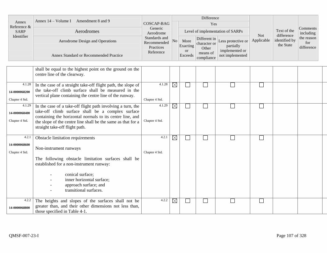
Annex
Reference &
SARP
Identifier
Annex 14 – Volume I Amendment 8 and 9 COSCAP-BAG
Generic
Aerodrome
Standards and
Recommended
Practices
Reference
Difference
Not
Applicable
Text of the
difference
identified by
the State
Comments
including
the reason
for
difference
No
Yes
Aerodromes Level of implementation of SARPs
Aerodrome Design and Operations
Annex Standard or Recommended Practice
More
Exacting
or
Exceeds
Different in
character or
Other
means of
compliance
Less protective or
partially
implemented or
not implemented
QMSF-007-23-I Page 107 of 328
shall be equal to the highest point on the ground on the
centre line of the clearway.
4.1.28
14-0000068200
Chapter 4 Std.
In the case of a straight take-off flight path, the slope of
the take-off climb surface shall be measured in the
vertical plane containing the centre line of the runway.
4.1.28
Chapter 4 Std.
4.1.29
14-0000068400
Chapter 4 Std.
In the case of a take-off flight path involving a turn, the
take-off climb surface shall be a complex surface
containing the horizontal normals to its centre line, and
the slope of the centre line shall be the same as that for a
straight take-off flight path.
4.1.29
Chapter 4 Std.
4.2.1
14-0000068600
Chapter 4 Std.
Obstacle limitation requirements
Non-instrument runways
The following obstacle limitation surfaces shall be
established for a non-instrument runway:
- conical surface;
- inner horizontal surface;
- approach surface; and
- transitional surfaces.
4.2.1
Chapter 4 Std.
4.2.2
14-0000068800
The heights and slopes of the surfaces shall not be
greater than, and their other dimensions not less than,
those specified in Table 4-1.
4.2.2
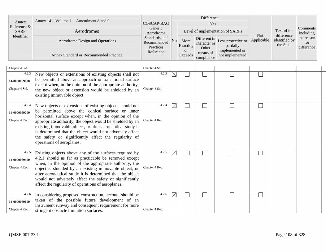
Annex
Reference &
SARP
Identifier
Annex 14 – Volume I Amendment 8 and 9 COSCAP-BAG
Generic
Aerodrome
Standards and
Recommended
Practices
Reference
Difference
Not
Applicable
Text of the
difference
identified by
the State
Comments
including
the reason
for
difference
No
Yes
Aerodromes Level of implementation of SARPs
Aerodrome Design and Operations
Annex Standard or Recommended Practice
More
Exacting
or
Exceeds
Different in
character or
Other
means of
compliance
Less protective or
partially
implemented or
not implemented
QMSF-007-23-I Page 108 of 328
Chapter 4 Std. Chapter 4 Std.
4.2.3
14-0000069000
Chapter 4 Std.
New objects or extensions of existing objects shall not
be permitted above an approach or transitional surface
except when, in the opinion of the appropriate authority,
the new object or extension would be shielded by an
existing immovable object.
4.2.3
Chapter 4 Std.
4.2.4
14-0000069200
Chapter 4 Rec.
New objects or extensions of existing objects should not
be permitted above the conical surface or inner
horizontal surface except when, in the opinion of the
appropriate authority, the object would be shielded by an
existing immovable object, or after aeronautical study it
is determined that the object would not adversely affect
the safety or significantly affect the regularity of
operations of aeroplanes.
4.2.4
Chapter 4 Rec.
4.2.5
14-0000069400
Chapter 4 Rec.
Existing objects above any of the surfaces required by
4.2.1 should as far as practicable be removed except
when, in the opinion of the appropriate authority, the
object is shielded by an existing immovable object, or
after aeronautical study it is determined that the object
would not adversely affect the safety or significantly
affect the regularity of operations of aeroplanes.
4.2.5
Chapter 4 Rec.
4.2.6
14-0000069600
Chapter 4 Rec.
In considering proposed construction, account should be
taken of the possible future development of an
instrument runway and consequent requirement for more
stringent obstacle limitation surfaces.
4.2.6
Chapter 4 Rec.
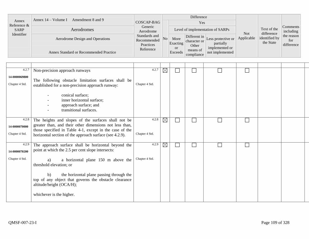
Annex
Reference &
SARP
Identifier
Annex 14 – Volume I Amendment 8 and 9 COSCAP-BAG
Generic
Aerodrome
Standards and
Recommended
Practices
Reference
Difference
Not
Applicable
Text of the
difference
identified by
the State
Comments
including
the reason
for
difference
No
Yes
Aerodromes Level of implementation of SARPs
Aerodrome Design and Operations
Annex Standard or Recommended Practice
More
Exacting
or
Exceeds
Different in
character or
Other
means of
compliance
Less protective or
partially
implemented or
not implemented
QMSF-007-23-I Page 109 of 328
4.2.7
14-0000069800
Chapter 4 Std.
Non-precision approach runways
The following obstacle limitation surfaces shall be
established for a non-precision approach runway:
- conical surface;
- inner horizontal surface;
- approach surface; and
- transitional surfaces.
4.2.7
Chapter 4 Std.
4.2.8
14-0000070000
Chapter 4 Std.
The heights and slopes of the surfaces shall not be
greater than, and their other dimensions not less than,
those specified in Table 4-1, except in the case of the
horizontal section of the approach surface (see 4.2.9).
4.2.8
Chapter 4 Std.
4.2.9
14-0000070200
Chapter 4 Std.
The approach surface shall be horizontal beyond the
point at which the 2.5 per cent slope intersects:
a) a horizontal plane 150 m above the
threshold elevation; or
b) the horizontal plane passing through the
top of any object that governs the obstacle clearance
altitude/height (OCA/H);
whichever is the higher.
4.2.9
Chapter 4 Std.
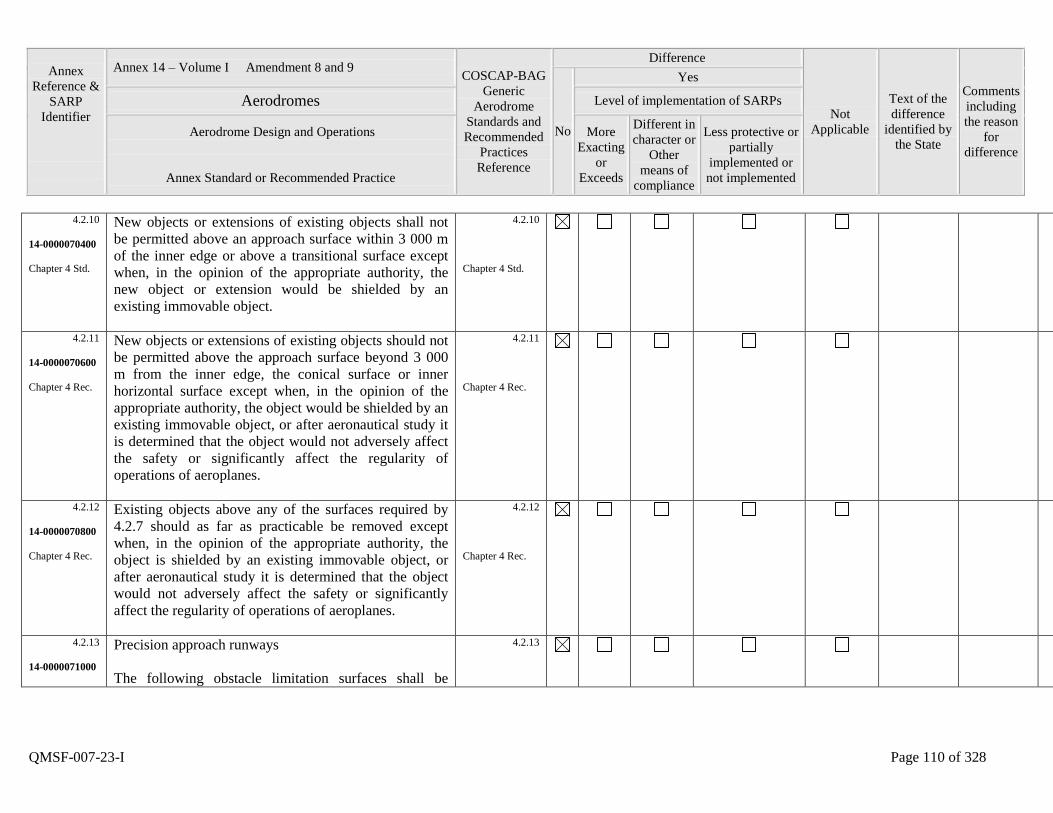
Annex
Reference &
SARP
Identifier
Annex 14 – Volume I Amendment 8 and 9 COSCAP-BAG
Generic
Aerodrome
Standards and
Recommended
Practices
Reference
Difference
Not
Applicable
Text of the
difference
identified by
the State
Comments
including
the reason
for
difference
No
Yes
Aerodromes Level of implementation of SARPs
Aerodrome Design and Operations
Annex Standard or Recommended Practice
More
Exacting
or
Exceeds
Different in
character or
Other
means of
compliance
Less protective or
partially
implemented or
not implemented
QMSF-007-23-I Page 110 of 328
4.2.10
14-0000070400
Chapter 4 Std.
New objects or extensions of existing objects shall not
be permitted above an approach surface within 3 000 m
of the inner edge or above a transitional surface except
when, in the opinion of the appropriate authority, the
new object or extension would be shielded by an
existing immovable object.
4.2.10
Chapter 4 Std.
4.2.11
14-0000070600
Chapter 4 Rec.
New objects or extensions of existing objects should not
be permitted above the approach surface beyond 3 000
m from the inner edge, the conical surface or inner
horizontal surface except when, in the opinion of the
appropriate authority, the object would be shielded by an
existing immovable object, or after aeronautical study it
is determined that the object would not adversely affect
the safety or significantly affect the regularity of
operations of aeroplanes.
4.2.11
Chapter 4 Rec.
4.2.12
14-0000070800
Chapter 4 Rec.
Existing objects above any of the surfaces required by
4.2.7 should as far as practicable be removed except
when, in the opinion of the appropriate authority, the
object is shielded by an existing immovable object, or
after aeronautical study it is determined that the object
would not adversely affect the safety or significantly
affect the regularity of operations of aeroplanes.
4.2.12
Chapter 4 Rec.
4.2.13
14-0000071000
Precision approach runways
The following obstacle limitation surfaces shall be
4.2.13
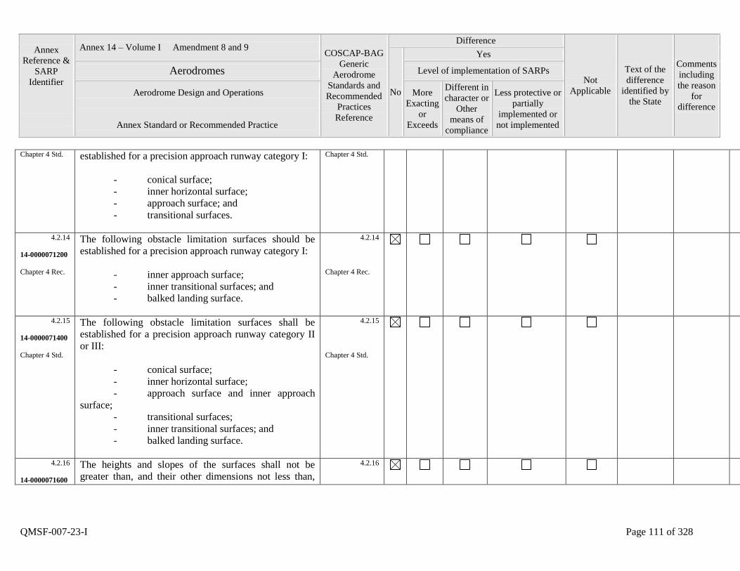
Annex
Reference &
SARP
Identifier
Annex 14 – Volume I Amendment 8 and 9 COSCAP-BAG
Generic
Aerodrome
Standards and
Recommended
Practices
Reference
Difference
Not
Applicable
Text of the
difference
identified by
the State
Comments
including
the reason
for
difference
No
Yes
Aerodromes Level of implementation of SARPs
Aerodrome Design and Operations
Annex Standard or Recommended Practice
More
Exacting
or
Exceeds
Different in
character or
Other
means of
compliance
Less protective or
partially
implemented or
not implemented
QMSF-007-23-I Page 111 of 328
Chapter 4 Std. established for a precision approach runway category I:
- conical surface;
- inner horizontal surface;
- approach surface; and
- transitional surfaces.
Chapter 4 Std.
4.2.14
14-0000071200
Chapter 4 Rec.
The following obstacle limitation surfaces should be
established for a precision approach runway category I:
- inner approach surface;
- inner transitional surfaces; and
- balked landing surface.
4.2.14
Chapter 4 Rec.
4.2.15
14-0000071400
Chapter 4 Std.
The following obstacle limitation surfaces shall be
established for a precision approach runway category II
or III:
- conical surface;
- inner horizontal surface;
- approach surface and inner approach
surface;
- transitional surfaces;
- inner transitional surfaces; and
- balked landing surface.
4.2.15
Chapter 4 Std.
4.2.16
14-0000071600
The heights and slopes of the surfaces shall not be
greater than, and their other dimensions not less than,
4.2.16
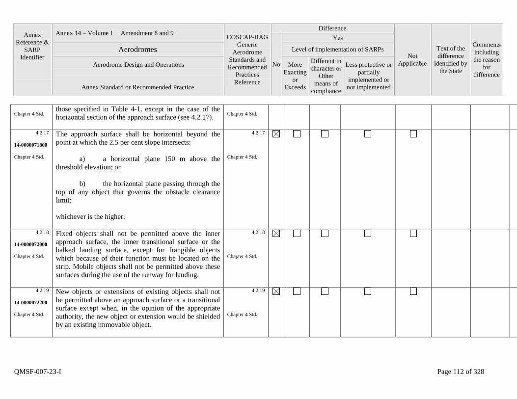
Annex
Reference &
SARP
Identifier
Annex 14 – Volume I Amendment 8 and 9 COSCAP-BAG
Generic
Aerodrome
Standards and
Recommended
Practices
Reference
Difference
Not
Applicable
Text of the
difference
identified by
the State
Comments
including
the reason
for
difference
No
Yes
Aerodromes Level of implementation of SARPs
Aerodrome Design and Operations
Annex Standard or Recommended Practice
More
Exacting
or
Exceeds
Different in
character or
Other
means of
compliance
Less protective or
partially
implemented or
not implemented
QMSF-007-23-I Page 112 of 328
Chapter 4 Std. those specified in Table 4-1, except in the case of the
horizontal section of the approach surface (see 4.2.17).
Chapter 4 Std.
4.2.17
14-0000071800
Chapter 4 Std.
The approach surface shall be horizontal beyond the
point at which the 2.5 per cent slope intersects:
a) a horizontal plane 150 m above the
threshold elevation; or
b) the horizontal plane passing through the
top of any object that governs the obstacle clearance
limit;
whichever is the higher.
4.2.17
Chapter 4 Std.
4.2.18
14-0000072000
Chapter 4 Std.
Fixed objects shall not be permitted above the inner
approach surface, the inner transitional surface or the
balked landing surface, except for frangible objects
which because of their function must be located on the
strip. Mobile objects shall not be permitted above these
surfaces during the use of the runway for landing.
4.2.18
Chapter 4 Std.
4.2.19
14-0000072200
Chapter 4 Std.
New objects or extensions of existing objects shall not
be permitted above an approach surface or a transitional
surface except when, in the opinion of the appropriate
authority, the new object or extension would be shielded
by an existing immovable object.
4.2.19
Chapter 4 Std.
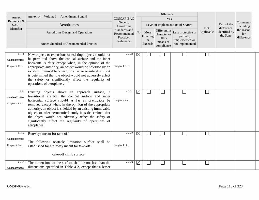
Annex
Reference &
SARP
Identifier
Annex 14 – Volume I Amendment 8 and 9 COSCAP-BAG
Generic
Aerodrome
Standards and
Recommended
Practices
Reference
Difference
Not
Applicable
Text of the
difference
identified by
the State
Comments
including
the reason
for
difference
No
Yes
Aerodromes Level of implementation of SARPs
Aerodrome Design and Operations
Annex Standard or Recommended Practice
More
Exacting
or
Exceeds
Different in
character or
Other
means of
compliance
Less protective or
partially
implemented or
not implemented
QMSF-007-23-I Page 113 of 328
4.2.20
14-0000072400
Chapter 4 Rec.
New objects or extensions of existing objects should not
be permitted above the conical surface and the inner
horizontal surface except when, in the opinion of the
appropriate authority, an object would be shielded by an
existing immovable object, or after aeronautical study it
is determined that the object would not adversely affect
the safety or significantly affect the regularity of
operations of aeroplanes.
4.2.20
Chapter 4 Rec.
4.2.21
14-0000072600
Chapter 4 Rec.
Existing objects above an approach surface, a
transitional surface, the conical surface and inner
horizontal surface should as far as practicable be
removed except when, in the opinion of the appropriate
authority, an object is shielded by an existing immovable
object, or after aeronautical study it is determined that
the object would not adversely affect the safety or
significantly affect the regularity of operations of
aeroplanes.
4.2.21
Chapter 4 Rec.
4.2.22
14-0000072800
Chapter 4 Std.
Runways meant for take-off
The following obstacle limitation surface shall be
established for a runway meant for take-off:
-take-off climb surface.
4.2.22
Chapter 4 Std.
4.2.23
14-0000073000
The dimensions of the surface shall be not less than the
dimensions specified in Table 4-2, except that a lesser
4.2.23
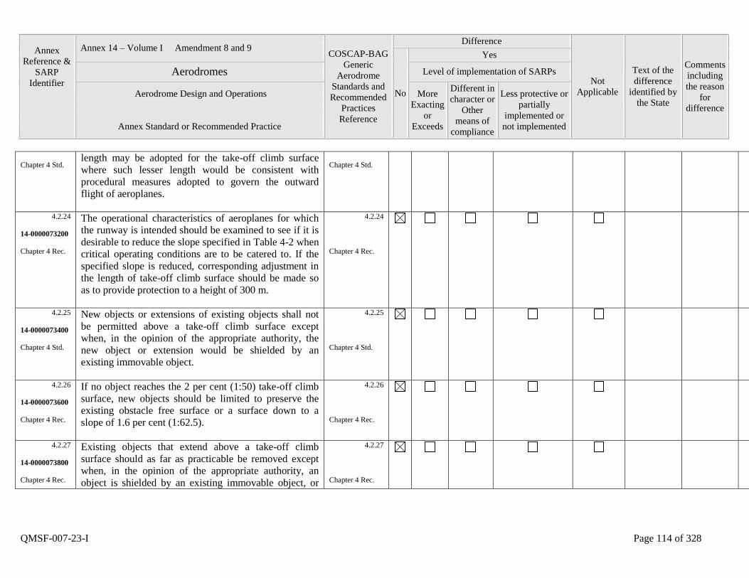
Annex
Reference &
SARP
Identifier
Annex 14 – Volume I Amendment 8 and 9 COSCAP-BAG
Generic
Aerodrome
Standards and
Recommended
Practices
Reference
Difference
Not
Applicable
Text of the
difference
identified by
the State
Comments
including
the reason
for
difference
No
Yes
Aerodromes Level of implementation of SARPs
Aerodrome Design and Operations
Annex Standard or Recommended Practice
More
Exacting
or
Exceeds
Different in
character or
Other
means of
compliance
Less protective or
partially
implemented or
not implemented
QMSF-007-23-I Page 114 of 328
Chapter 4 Std. length may be adopted for the take-off climb surface
where such lesser length would be consistent with
procedural measures adopted to govern the outward
flight of aeroplanes.
Chapter 4 Std.
4.2.24
14-0000073200
Chapter 4 Rec.
The operational characteristics of aeroplanes for which
the runway is intended should be examined to see if it is
desirable to reduce the slope specified in Table 4-2 when
critical operating conditions are to be catered to. If the
specified slope is reduced, corresponding adjustment in
the length of take-off climb surface should be made so
as to provide protection to a height of 300 m.
4.2.24
Chapter 4 Rec.
4.2.25
14-0000073400
Chapter 4 Std.
New objects or extensions of existing objects shall not
be permitted above a take-off climb surface except
when, in the opinion of the appropriate authority, the
new object or extension would be shielded by an
existing immovable object.
4.2.25
Chapter 4 Std.
4.2.26
14-0000073600
Chapter 4 Rec.
If no object reaches the 2 per cent (1:50) take-off climb
surface, new objects should be limited to preserve the
existing obstacle free surface or a surface down to a
slope of 1.6 per cent (1:62.5).
4.2.26
Chapter 4 Rec.
4.2.27
14-0000073800
Chapter 4 Rec.
Existing objects that extend above a take-off climb
surface should as far as practicable be removed except
when, in the opinion of the appropriate authority, an
object is shielded by an existing immovable object, or
4.2.27
Chapter 4 Rec.
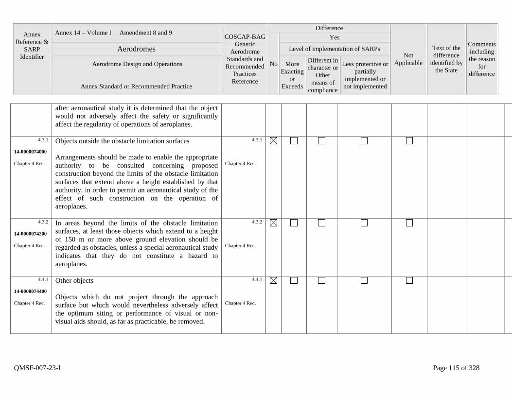
Annex
Reference &
SARP
Identifier
Annex 14 – Volume I Amendment 8 and 9 COSCAP-BAG
Generic
Aerodrome
Standards and
Recommended
Practices
Reference
Difference
Not
Applicable
Text of the
difference
identified by
the State
Comments
including
the reason
for
difference
No
Yes
Aerodromes Level of implementation of SARPs
Aerodrome Design and Operations
Annex Standard or Recommended Practice
More
Exacting
or
Exceeds
Different in
character or
Other
means of
compliance
Less protective or
partially
implemented or
not implemented
QMSF-007-23-I Page 115 of 328
after aeronautical study it is determined that the object
would not adversely affect the safety or significantly
affect the regularity of operations of aeroplanes.
4.3.1
14-0000074000
Chapter 4 Rec.
Objects outside the obstacle limitation surfaces
Arrangements should be made to enable the appropriate
authority to be consulted concerning proposed
construction beyond the limits of the obstacle limitation
surfaces that extend above a height established by that
authority, in order to permit an aeronautical study of the
effect of such construction on the operation of
aeroplanes.
4.3.1
Chapter 4 Rec.
4.3.2
14-0000074200
Chapter 4 Rec.
In areas beyond the limits of the obstacle limitation
surfaces, at least those objects which extend to a height
of 150 m or more above ground elevation should be
regarded as obstacles, unless a special aeronautical study
indicates that they do not constitute a hazard to
aeroplanes.
4.3.2
Chapter 4 Rec.
4.4.1
14-0000074400
Chapter 4 Rec.
Other objects
Objects which do not project through the approach
surface but which would nevertheless adversely affect
the optimum siting or performance of visual or non-
visual aids should, as far as practicable, be removed.
4.4.1
Chapter 4 Rec.
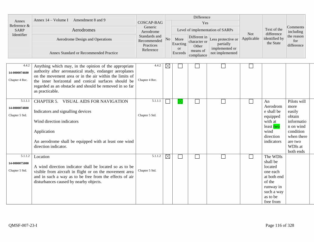
Annex
Reference &
SARP
Identifier
Annex 14 – Volume I Amendment 8 and 9 COSCAP-BAG
Generic
Aerodrome
Standards and
Recommended
Practices
Reference
Difference
Not
Applicable
Text of the
difference
identified by
the State
Comments
including
the reason
for
difference
No
Yes
Aerodromes Level of implementation of SARPs
Aerodrome Design and Operations
Annex Standard or Recommended Practice
More
Exacting
or
Exceeds
Different in
character or
Other
means of
compliance
Less protective or
partially
implemented or
not implemented
QMSF-007-23-I Page 116 of 328
4.4.2
14-0000074600
Chapter 4 Rec.
Anything which may, in the opinion of the appropriate
authority after aeronautical study, endanger aeroplanes
on the movement area or in the air within the limits of
the inner horizontal and conical surfaces should be
regarded as an obstacle and should be removed in so far
as practicable.
4.4.2
Chapter 4 Rec.
5.1.1.1
14-0000074800
Chapter 5 Std.
CHAPTER 5. VISUAL AIDS FOR NAVIGATION
Indicators and signalling devices
Wind direction indicators
Application
An aerodrome shall be equipped with at least one wind
direction indicator.
5.1.1.1
Chapter 5 Std.
An
Aerodrom
e shall be
equipped
with at
least two
wind
direction
indicators
Pilots will
more
easily
obtain
informatio
n on wind
condition
when there
are two
WDIs at
both ends
5.1.1.2
14-0000075000
Chapter 5 Std.
Location
A wind direction indicator shall be located so as to be
visible from aircraft in flight or on the movement area
and in such a way as to be free from the effects of air
disturbances caused by nearby objects.
5.1.1.2
Chapter 5 Std.
The WDIs
shall be
located
one each
at both end
of the
runway in
such a way
as to be
free from
Annex
Reference &
SARP
Identifier
Annex 14 – Volume I Amendment 8 and 9 COSCAP-BAG
Generic
Aerodrome
Standards and
Recommended
Practices
Reference
Difference
Not
Applicable
Text of the
difference
identified by
the State
Comments
including
the reason
for
difference
No
Yes
Aerodromes Level of implementation of SARPs
Aerodrome Design and Operations
Annex Standard or Recommended Practice
More
Exacting
or
Exceeds
Different in
character or
Other
means of
compliance
Less protective or
partially
implemented or
not implemented
QMSF-007-23-I Page 117 of 328
the effects
of air
disturbanc
es caused
by nearby
objects
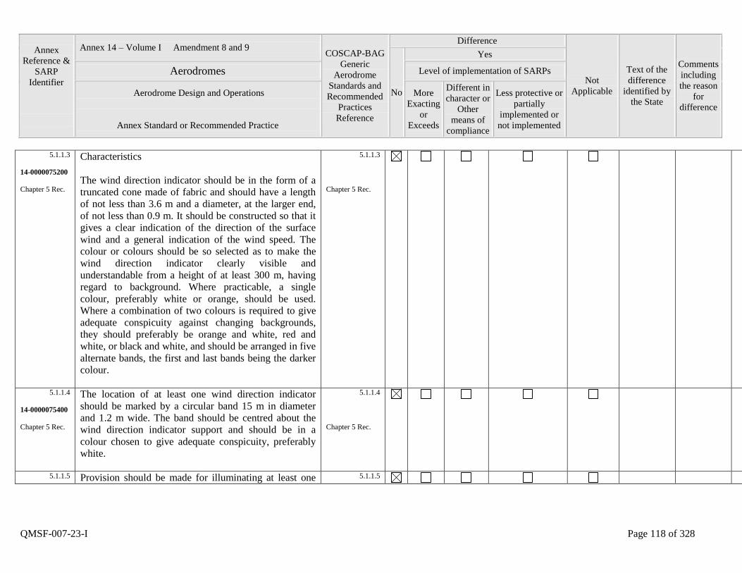
Annex
Reference &
SARP
Identifier
Annex 14 – Volume I Amendment 8 and 9 COSCAP-BAG
Generic
Aerodrome
Standards and
Recommended
Practices
Reference
Difference
Not
Applicable
Text of the
difference
identified by
the State
Comments
including
the reason
for
difference
No
Yes
Aerodromes Level of implementation of SARPs
Aerodrome Design and Operations
Annex Standard or Recommended Practice
More
Exacting
or
Exceeds
Different in
character or
Other
means of
compliance
Less protective or
partially
implemented or
not implemented
QMSF-007-23-I Page 118 of 328
5.1.1.3
14-0000075200
Chapter 5 Rec.
Characteristics
The wind direction indicator should be in the form of a
truncated cone made of fabric and should have a length
of not less than 3.6 m and a diameter, at the larger end,
of not less than 0.9 m. It should be constructed so that it
gives a clear indication of the direction of the surface
wind and a general indication of the wind speed. The
colour or colours should be so selected as to make the
wind direction indicator clearly visible and
understandable from a height of at least 300 m, having
regard to background. Where practicable, a single
colour, preferably white or orange, should be used.
Where a combination of two colours is required to give
adequate conspicuity against changing backgrounds,
they should preferably be orange and white, red and
white, or black and white, and should be arranged in five
alternate bands, the first and last bands being the darker
colour.
5.1.1.3
Chapter 5 Rec.
5.1.1.4
14-0000075400
Chapter 5 Rec.
The location of at least one wind direction indicator
should be marked by a circular band 15 m in diameter
and 1.2 m wide. The band should be centred about the
wind direction indicator support and should be in a
colour chosen to give adequate conspicuity, preferably
white.
5.1.1.4
Chapter 5 Rec.
5.1.1.5 Provision should be made for illuminating at least one 5.1.1.5
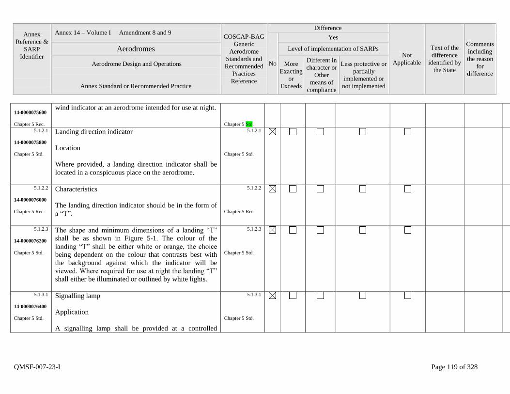
Annex
Reference &
SARP
Identifier
Annex 14 – Volume I Amendment 8 and 9 COSCAP-BAG
Generic
Aerodrome
Standards and
Recommended
Practices
Reference
Difference
Not
Applicable
Text of the
difference
identified by
the State
Comments
including
the reason
for
difference
No
Yes
Aerodromes Level of implementation of SARPs
Aerodrome Design and Operations
Annex Standard or Recommended Practice
More
Exacting
or
Exceeds
Different in
character or
Other
means of
compliance
Less protective or
partially
implemented or
not implemented
QMSF-007-23-I Page 119 of 328
14-0000075600
Chapter 5 Rec.
wind indicator at an aerodrome intended for use at night.
Chapter 5 Std.
5.1.2.1
14-0000075800
Chapter 5 Std.
Landing direction indicator
Location
Where provided, a landing direction indicator shall be
located in a conspicuous place on the aerodrome.
5.1.2.1
Chapter 5 Std.
5.1.2.2
14-0000076000
Chapter 5 Rec.
Characteristics
The landing direction indicator should be in the form of
a “T”.
5.1.2.2
Chapter 5 Rec.
5.1.2.3
14-0000076200
Chapter 5 Std.
The shape and minimum dimensions of a landing “T”
shall be as shown in Figure 5-1. The colour of the
landing “T” shall be either white or orange, the choice
being dependent on the colour that contrasts best with
the background against which the indicator will be
viewed. Where required for use at night the landing “T”
shall either be illuminated or outlined by white lights.
5.1.2.3
Chapter 5 Std.
5.1.3.1
14-0000076400
Chapter 5 Std.
Signalling lamp
Application
A signalling lamp shall be provided at a controlled
5.1.3.1
Chapter 5 Std.
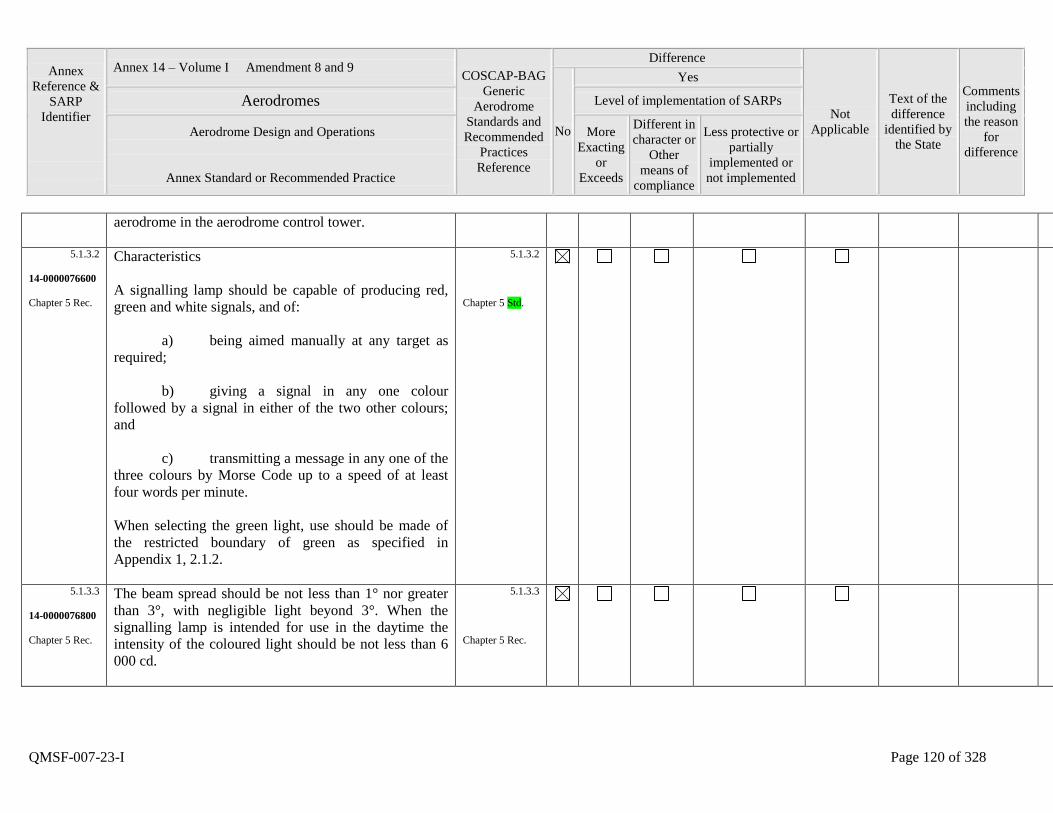
Annex
Reference &
SARP
Identifier
Annex 14 – Volume I Amendment 8 and 9 COSCAP-BAG
Generic
Aerodrome
Standards and
Recommended
Practices
Reference
Difference
Not
Applicable
Text of the
difference
identified by
the State
Comments
including
the reason
for
difference
No
Yes
Aerodromes Level of implementation of SARPs
Aerodrome Design and Operations
Annex Standard or Recommended Practice
More
Exacting
or
Exceeds
Different in
character or
Other
means of
compliance
Less protective or
partially
implemented or
not implemented
QMSF-007-23-I Page 120 of 328
aerodrome in the aerodrome control tower.
5.1.3.2
14-0000076600
Chapter 5 Rec.
Characteristics
A signalling lamp should be capable of producing red,
green and white signals, and of:
a) being aimed manually at any target as
required;
b) giving a signal in any one colour
followed by a signal in either of the two other colours;
and
c) transmitting a message in any one of the
three colours by Morse Code up to a speed of at least
four words per minute.
When selecting the green light, use should be made of
the restricted boundary of green as specified in
Appendix 1, 2.1.2.
5.1.3.2
Chapter 5 Std.
5.1.3.3
14-0000076800
Chapter 5 Rec.
The beam spread should be not less than 1° nor greater
than 3°, with negligible light beyond 3°. When the
signalling lamp is intended for use in the daytime the
intensity of the coloured light should be not less than 6
000 cd.
5.1.3.3
Chapter 5 Rec.
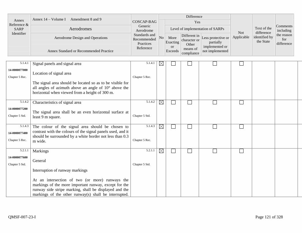
Annex
Reference &
SARP
Identifier
Annex 14 – Volume I Amendment 8 and 9 COSCAP-BAG
Generic
Aerodrome
Standards and
Recommended
Practices
Reference
Difference
Not
Applicable
Text of the
difference
identified by
the State
Comments
including
the reason
for
difference
No
Yes
Aerodromes Level of implementation of SARPs
Aerodrome Design and Operations
Annex Standard or Recommended Practice
More
Exacting
or
Exceeds
Different in
character or
Other
means of
compliance
Less protective or
partially
implemented or
not implemented
QMSF-007-23-I Page 121 of 328
5.1.4.1
14-0000077000
Chapter 5 Rec.
Signal panels and signal area
Location of signal area
The signal area should be located so as to be visible for
all angles of azimuth above an angle of 10° above the
horizontal when viewed from a height of 300 m.
5.1.4.1
Chapter 5 Rec.
5.1.4.2
14-0000077200
Chapter 5 Std.
Characteristics of signal area
The signal area shall be an even horizontal surface at
least 9 m square.
5.1.4.2
Chapter 5 Std.
5.1.4.3
14-0000077400
Chapter 5 Rec.
The colour of the signal area should be chosen to
contrast with the colours of the signal panels used, and it
should be surrounded by a white border not less than 0.3
m wide.
5.1.4.3
Chapter 5 Rec.
5.2.1.1
14-0000077600
Chapter 5 Std.
Markings
General
Interruption of runway markings
At an intersection of two (or more) runways the
markings of the more important runway, except for the
runway side stripe marking, shall be displayed and the
markings of the other runway(s) shall be interrupted.
5.2.1.1
Chapter 5 Std.
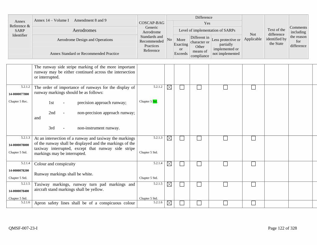
Annex
Reference &
SARP
Identifier
Annex 14 – Volume I Amendment 8 and 9 COSCAP-BAG
Generic
Aerodrome
Standards and
Recommended
Practices
Reference
Difference
Not
Applicable
Text of the
difference
identified by
the State
Comments
including
the reason
for
difference
No
Yes
Aerodromes Level of implementation of SARPs
Aerodrome Design and Operations
Annex Standard or Recommended Practice
More
Exacting
or
Exceeds
Different in
character or
Other
means of
compliance
Less protective or
partially
implemented or
not implemented
QMSF-007-23-I Page 122 of 328
The runway side stripe marking of the more important
runway may be either continued across the intersection
or interrupted.
5.2.1.2
14-0000077800
Chapter 5 Rec.
The order of importance of runways for the display of
runway markings should be as follows:
1st - precision approach runway;
2nd - non-precision approach runway;
and
3rd - non-instrument runway.
5.2.1.2
Chapter 5 Std.
5.2.1.3
14-0000078000
Chapter 5 Std.
At an intersection of a runway and taxiway the markings
of the runway shall be displayed and the markings of the
taxiway interrupted, except that runway side stripe
markings may be interrupted.
5.2.1.3
Chapter 5 Std.
5.2.1.4
14-0000078200
Chapter 5 Std.
Colour and conspicuity
Runway markings shall be white.
5.2.1.4
Chapter 5 Std.
5.2.1.5
14-0000078400
Chapter 5 Std.
Taxiway markings, runway turn pad markings and
aircraft stand markings shall be yellow.
5.2.1.5
Chapter 5 Std.
5.2.1.6
Apron safety lines shall be of a conspicuous colour 5.2.1.6
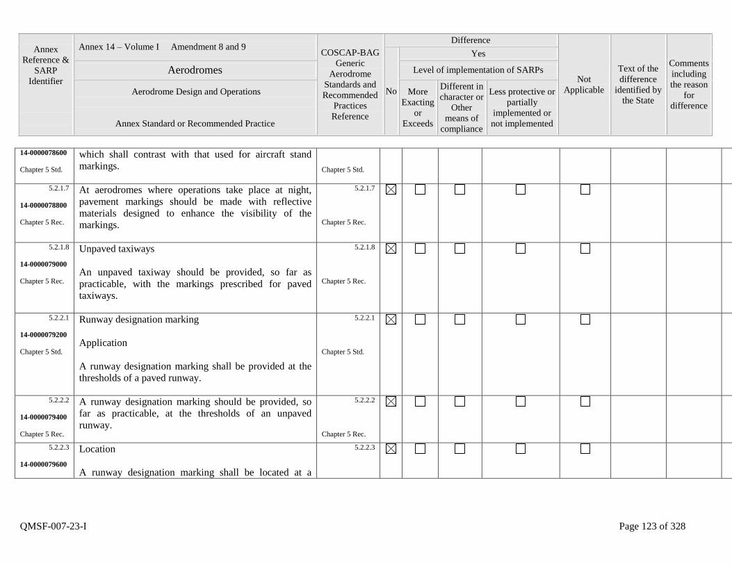
Annex
Reference &
SARP
Identifier
Annex 14 – Volume I Amendment 8 and 9 COSCAP-BAG
Generic
Aerodrome
Standards and
Recommended
Practices
Reference
Difference
Not
Applicable
Text of the
difference
identified by
the State
Comments
including
the reason
for
difference
No
Yes
Aerodromes Level of implementation of SARPs
Aerodrome Design and Operations
Annex Standard or Recommended Practice
More
Exacting
or
Exceeds
Different in
character or
Other
means of
compliance
Less protective or
partially
implemented or
not implemented
QMSF-007-23-I Page 123 of 328
14-0000078600
Chapter 5 Std.
which shall contrast with that used for aircraft stand
markings.
Chapter 5 Std.
5.2.1.7
14-0000078800
Chapter 5 Rec.
At aerodromes where operations take place at night,
pavement markings should be made with reflective
materials designed to enhance the visibility of the
markings.
5.2.1.7
Chapter 5 Rec.
5.2.1.8
14-0000079000
Chapter 5 Rec.
Unpaved taxiways
An unpaved taxiway should be provided, so far as
practicable, with the markings prescribed for paved
taxiways.
5.2.1.8
Chapter 5 Rec.
5.2.2.1
14-0000079200
Chapter 5 Std.
Runway designation marking
Application
A runway designation marking shall be provided at the
thresholds of a paved runway.
5.2.2.1
Chapter 5 Std.
5.2.2.2
14-0000079400
Chapter 5 Rec.
A runway designation marking should be provided, so
far as practicable, at the thresholds of an unpaved
runway.
5.2.2.2
Chapter 5 Rec.
5.2.2.3
14-0000079600
Location
A runway designation marking shall be located at a
5.2.2.3
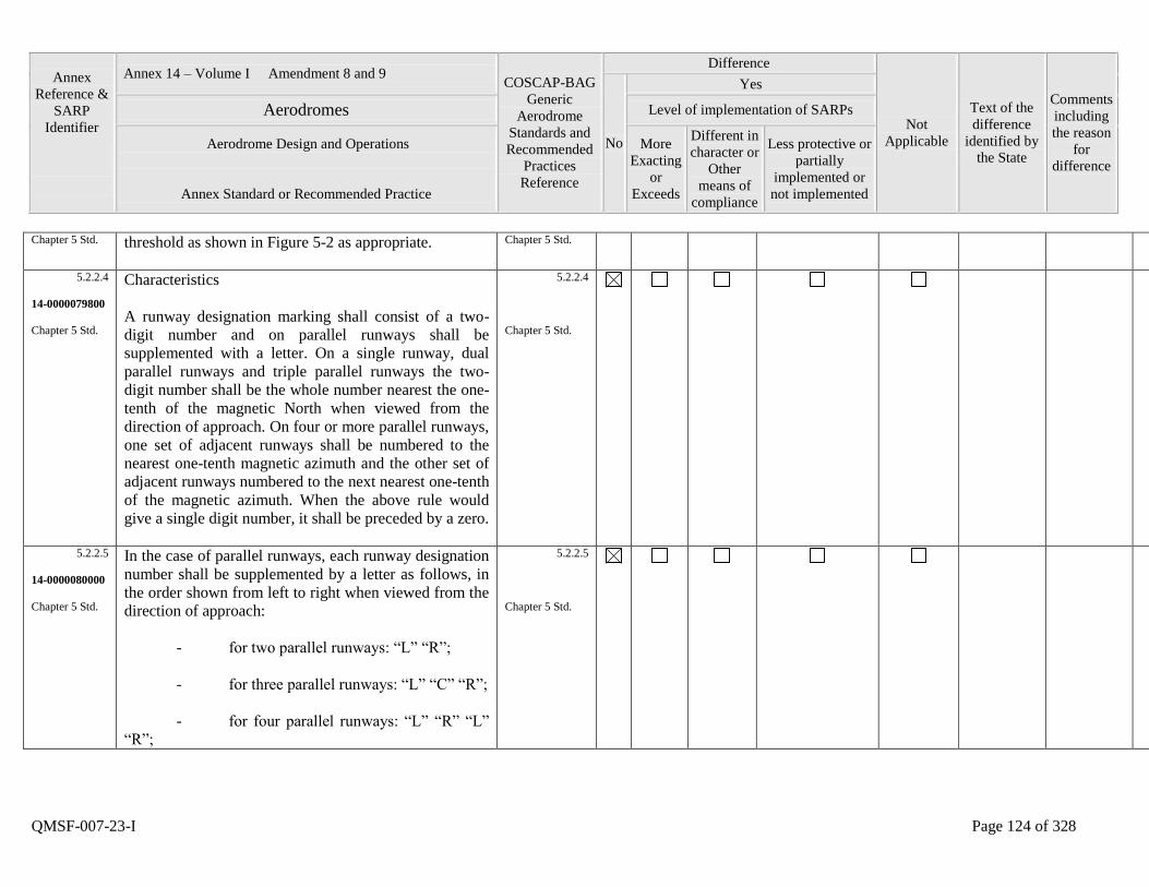
Annex
Reference &
SARP
Identifier
Annex 14 – Volume I Amendment 8 and 9 COSCAP-BAG
Generic
Aerodrome
Standards and
Recommended
Practices
Reference
Difference
Not
Applicable
Text of the
difference
identified by
the State
Comments
including
the reason
for
difference
No
Yes
Aerodromes Level of implementation of SARPs
Aerodrome Design and Operations
Annex Standard or Recommended Practice
More
Exacting
or
Exceeds
Different in
character or
Other
means of
compliance
Less protective or
partially
implemented or
not implemented
QMSF-007-23-I Page 124 of 328
Chapter 5 Std. threshold as shown in Figure 5-2 as appropriate.
Chapter 5 Std.
5.2.2.4
14-0000079800
Chapter 5 Std.
Characteristics
A runway designation marking shall consist of a two-
digit number and on parallel runways shall be
supplemented with a letter. On a single runway, dual
parallel runways and triple parallel runways the two-
digit number shall be the whole number nearest the one-
tenth of the magnetic North when viewed from the
direction of approach. On four or more parallel runways,
one set of adjacent runways shall be numbered to the
nearest one-tenth magnetic azimuth and the other set of
adjacent runways numbered to the next nearest one-tenth
of the magnetic azimuth. When the above rule would
give a single digit number, it shall be preceded by a zero.
5.2.2.4
Chapter 5 Std.
5.2.2.5
14-0000080000
Chapter 5 Std.
In the case of parallel runways, each runway designation
number shall be supplemented by a letter as follows, in
the order shown from left to right when viewed from the
direction of approach:
- for two parallel runways: “L” “R”;
- for three parallel runways: “L” “C” “R”;
- for four parallel runways: “L” “R” “L”
“R”;
5.2.2.5
Chapter 5 Std.
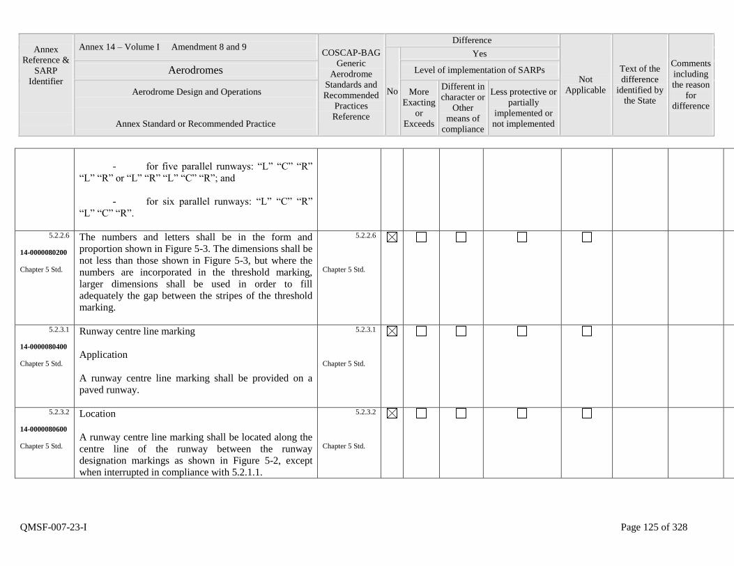
Annex
Reference &
SARP
Identifier
Annex 14 – Volume I Amendment 8 and 9 COSCAP-BAG
Generic
Aerodrome
Standards and
Recommended
Practices
Reference
Difference
Not
Applicable
Text of the
difference
identified by
the State
Comments
including
the reason
for
difference
No
Yes
Aerodromes Level of implementation of SARPs
Aerodrome Design and Operations
Annex Standard or Recommended Practice
More
Exacting
or
Exceeds
Different in
character or
Other
means of
compliance
Less protective or
partially
implemented or
not implemented
QMSF-007-23-I Page 125 of 328
- for five parallel runways: “L” “C” “R”
“L” “R” or “L” “R” “L” “C” “R”; and
- for six parallel runways: “L” “C” “R”
“L” “C” “R”.
5.2.2.6
14-0000080200
Chapter 5 Std.
The numbers and letters shall be in the form and
proportion shown in Figure 5-3. The dimensions shall be
not less than those shown in Figure 5-3, but where the
numbers are incorporated in the threshold marking,
larger dimensions shall be used in order to fill
adequately the gap between the stripes of the threshold
marking.
5.2.2.6
Chapter 5 Std.
5.2.3.1
14-0000080400
Chapter 5 Std.
Runway centre line marking
Application
A runway centre line marking shall be provided on a
paved runway.
5.2.3.1
Chapter 5 Std.
5.2.3.2
14-0000080600
Chapter 5 Std.
Location
A runway centre line marking shall be located along the
centre line of the runway between the runway
designation markings as shown in Figure 5-2, except
when interrupted in compliance with 5.2.1.1.
5.2.3.2
Chapter 5 Std.
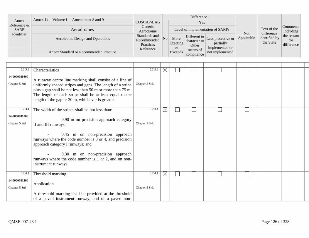
Annex
Reference &
SARP
Identifier
Annex 14 – Volume I Amendment 8 and 9 COSCAP-BAG
Generic
Aerodrome
Standards and
Recommended
Practices
Reference
Difference
Not
Applicable
Text of the
difference
identified by
the State
Comments
including
the reason
for
difference
No
Yes
Aerodromes Level of implementation of SARPs
Aerodrome Design and Operations
Annex Standard or Recommended Practice
More
Exacting
or
Exceeds
Different in
character or
Other
means of
compliance
Less protective or
partially
implemented or
not implemented
QMSF-007-23-I Page 126 of 328
5.2.3.3
14-0000080800
Chapter 5 Std.
Characteristics
A runway centre line marking shall consist of a line of
uniformly spaced stripes and gaps. The length of a stripe
plus a gap shall be not less than 50 m or more than 75 m.
The length of each stripe shall be at least equal to the
length of the gap or 30 m, whichever is greater.
5.2.3.3
Chapter 5 Std.
5.2.3.4
14-0000081000
Chapter 5 Std.
The width of the stripes shall be not less than:
- 0.90 m on precision approach category
II and III runways;
- 0.45 m on non-precision approach
runways where the code number is 3 or 4, and precision
approach category I runways; and
- 0.30 m on non-precision approach
runways where the code number is 1 or 2, and on non-
instrument runways.
5.2.3.4
Chapter 5 Std.
5.2.4.1
14-0000081200
Chapter 5 Std.
Threshold marking
Application
A threshold marking shall be provided at the threshold
of a paved instrument runway, and of a paved non-
5.2.4.1
Chapter 5 Std.
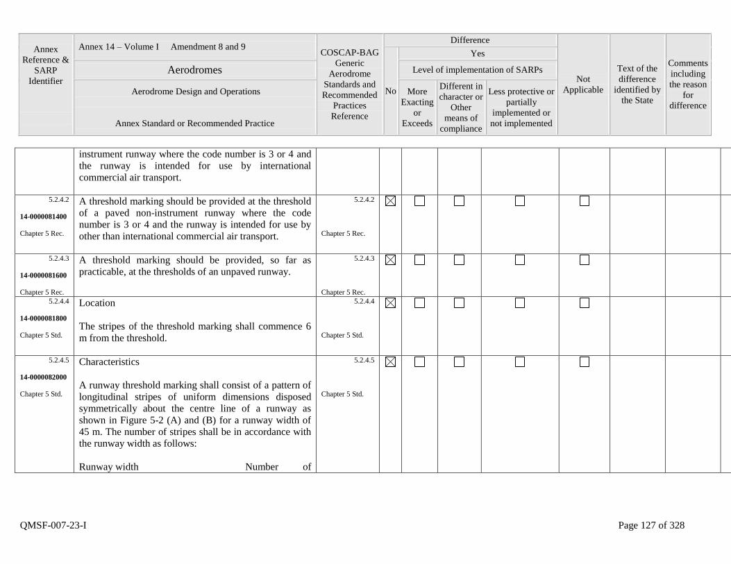
Annex
Reference &
SARP
Identifier
Annex 14 – Volume I Amendment 8 and 9 COSCAP-BAG
Generic
Aerodrome
Standards and
Recommended
Practices
Reference
Difference
Not
Applicable
Text of the
difference
identified by
the State
Comments
including
the reason
for
difference
No
Yes
Aerodromes Level of implementation of SARPs
Aerodrome Design and Operations
Annex Standard or Recommended Practice
More
Exacting
or
Exceeds
Different in
character or
Other
means of
compliance
Less protective or
partially
implemented or
not implemented
QMSF-007-23-I Page 127 of 328
instrument runway where the code number is 3 or 4 and
the runway is intended for use by international
commercial air transport.
5.2.4.2
14-0000081400
Chapter 5 Rec.
A threshold marking should be provided at the threshold
of a paved non-instrument runway where the code
number is 3 or 4 and the runway is intended for use by
other than international commercial air transport.
5.2.4.2
Chapter 5 Rec.
5.2.4.3
14-0000081600
Chapter 5 Rec.
A threshold marking should be provided, so far as
practicable, at the thresholds of an unpaved runway.
5.2.4.3
Chapter 5 Rec.
5.2.4.4
14-0000081800
Chapter 5 Std.
Location
The stripes of the threshold marking shall commence 6
m from the threshold.
5.2.4.4
Chapter 5 Std.
5.2.4.5
14-0000082000
Chapter 5 Std.
Characteristics
A runway threshold marking shall consist of a pattern of
longitudinal stripes of uniform dimensions disposed
symmetrically about the centre line of a runway as
shown in Figure 5-2 (A) and (B) for a runway width of
45 m. The number of stripes shall be in accordance with
the runway width as follows:
Runway width Number of
5.2.4.5
Chapter 5 Std.
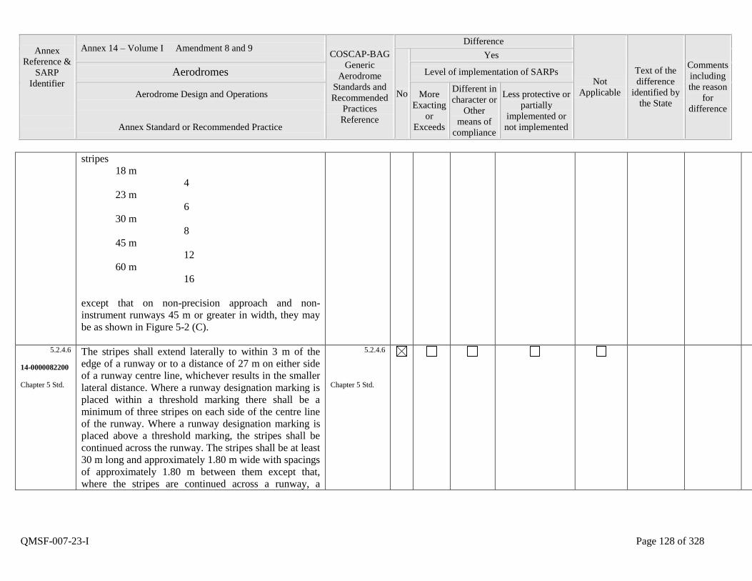
Annex
Reference &
SARP
Identifier
Annex 14 – Volume I Amendment 8 and 9 COSCAP-BAG
Generic
Aerodrome
Standards and
Recommended
Practices
Reference
Difference
Not
Applicable
Text of the
difference
identified by
the State
Comments
including
the reason
for
difference
No
Yes
Aerodromes Level of implementation of SARPs
Aerodrome Design and Operations
Annex Standard or Recommended Practice
More
Exacting
or
Exceeds
Different in
character or
Other
means of
compliance
Less protective or
partially
implemented or
not implemented
QMSF-007-23-I Page 128 of 328
stripes
18 m
4
23 m
6
30 m
8
45 m
12
60 m
16
except that on non-precision approach and non-
instrument runways 45 m or greater in width, they may
be as shown in Figure 5-2 (C).
5.2.4.6
14-0000082200
Chapter 5 Std.
The stripes shall extend laterally to within 3 m of the
edge of a runway or to a distance of 27 m on either side
of a runway centre line, whichever results in the smaller
lateral distance. Where a runway designation marking is
placed within a threshold marking there shall be a
minimum of three stripes on each side of the centre line
of the runway. Where a runway designation marking is
placed above a threshold marking, the stripes shall be
continued across the runway. The stripes shall be at least
30 m long and approximately 1.80 m wide with spacings
of approximately 1.80 m between them except that,
where the stripes are continued across a runway, a
5.2.4.6
Chapter 5 Std.
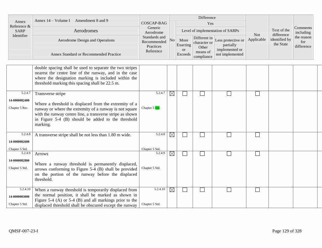
Annex
Reference &
SARP
Identifier
Annex 14 – Volume I Amendment 8 and 9 COSCAP-BAG
Generic
Aerodrome
Standards and
Recommended
Practices
Reference
Difference
Not
Applicable
Text of the
difference
identified by
the State
Comments
including
the reason
for
difference
No
Yes
Aerodromes Level of implementation of SARPs
Aerodrome Design and Operations
Annex Standard or Recommended Practice
More
Exacting
or
Exceeds
Different in
character or
Other
means of
compliance
Less protective or
partially
implemented or
not implemented
QMSF-007-23-I Page 129 of 328
double spacing shall be used to separate the two stripes
nearest the centre line of the runway, and in the case
where the designation marking is included within the
threshold marking this spacing shall be 22.5 m.
5.2.4.7
14-0000082400
Chapter 5 Rec.
Transverse stripe
Where a threshold is displaced from the extremity of a
runway or where the extremity of a runway is not square
with the runway centre line, a transverse stripe as shown
in Figure 5-4 (B) should be added to the threshold
marking.
5.2.4.7
Chapter 5 Std.
5.2.4.8
14-0000082600
Chapter 5 Std.
A transverse stripe shall be not less than 1.80 m wide.
5.2.4.8
Chapter 5 Std.
5.2.4.9
14-0000082800
Chapter 5 Std.
Arrows
Where a runway threshold is permanently displaced,
arrows conforming to Figure 5-4 (B) shall be provided
on the portion of the runway before the displaced
threshold.
5.2.4.9
Chapter 5 Std.
5.2.4.10
14-0000083000
Chapter 5 Std.
When a runway threshold is temporarily displaced from
the normal position, it shall be marked as shown in
Figure 5-4 (A) or 5-4 (B) and all markings prior to the
displaced threshold shall be obscured except the runway
5.2.4.10
Chapter 5 Std.
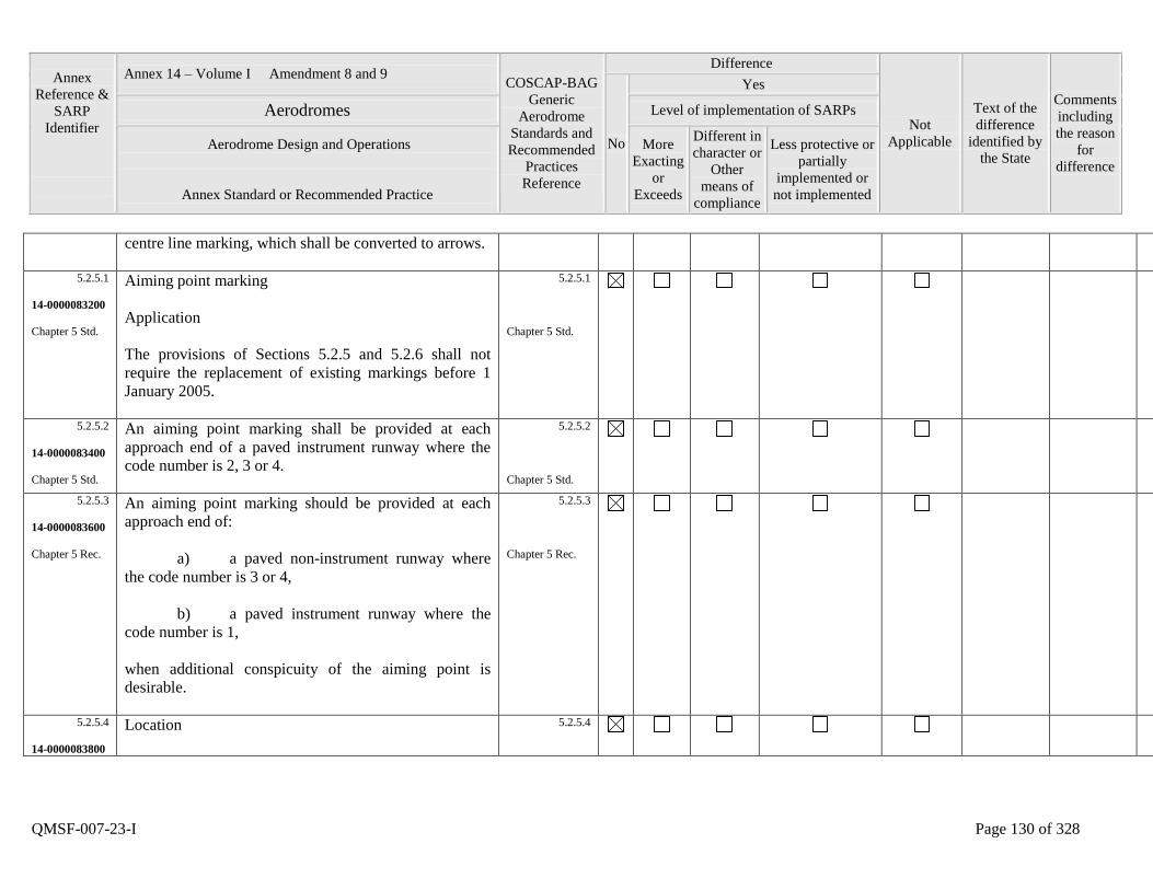
Annex
Reference &
SARP
Identifier
Annex 14 – Volume I Amendment 8 and 9 COSCAP-BAG
Generic
Aerodrome
Standards and
Recommended
Practices
Reference
Difference
Not
Applicable
Text of the
difference
identified by
the State
Comments
including
the reason
for
difference
No
Yes
Aerodromes Level of implementation of SARPs
Aerodrome Design and Operations
Annex Standard or Recommended Practice
More
Exacting
or
Exceeds
Different in
character or
Other
means of
compliance
Less protective or
partially
implemented or
not implemented
QMSF-007-23-I Page 130 of 328
centre line marking, which shall be converted to arrows.
5.2.5.1
14-0000083200
Chapter 5 Std.
Aiming point marking
Application
The provisions of Sections 5.2.5 and 5.2.6 shall not
require the replacement of existing markings before 1
January 2005.
5.2.5.1
Chapter 5 Std.
5.2.5.2
14-0000083400
Chapter 5 Std.
An aiming point marking shall be provided at each
approach end of a paved instrument runway where the
code number is 2, 3 or 4.
5.2.5.2
Chapter 5 Std.
5.2.5.3
14-0000083600
Chapter 5 Rec.
An aiming point marking should be provided at each
approach end of:
a) a paved non-instrument runway where
the code number is 3 or 4,
b) a paved instrument runway where the
code number is 1,
when additional conspicuity of the aiming point is
desirable.
5.2.5.3
Chapter 5 Rec.
5.2.5.4
14-0000083800
Location
5.2.5.4
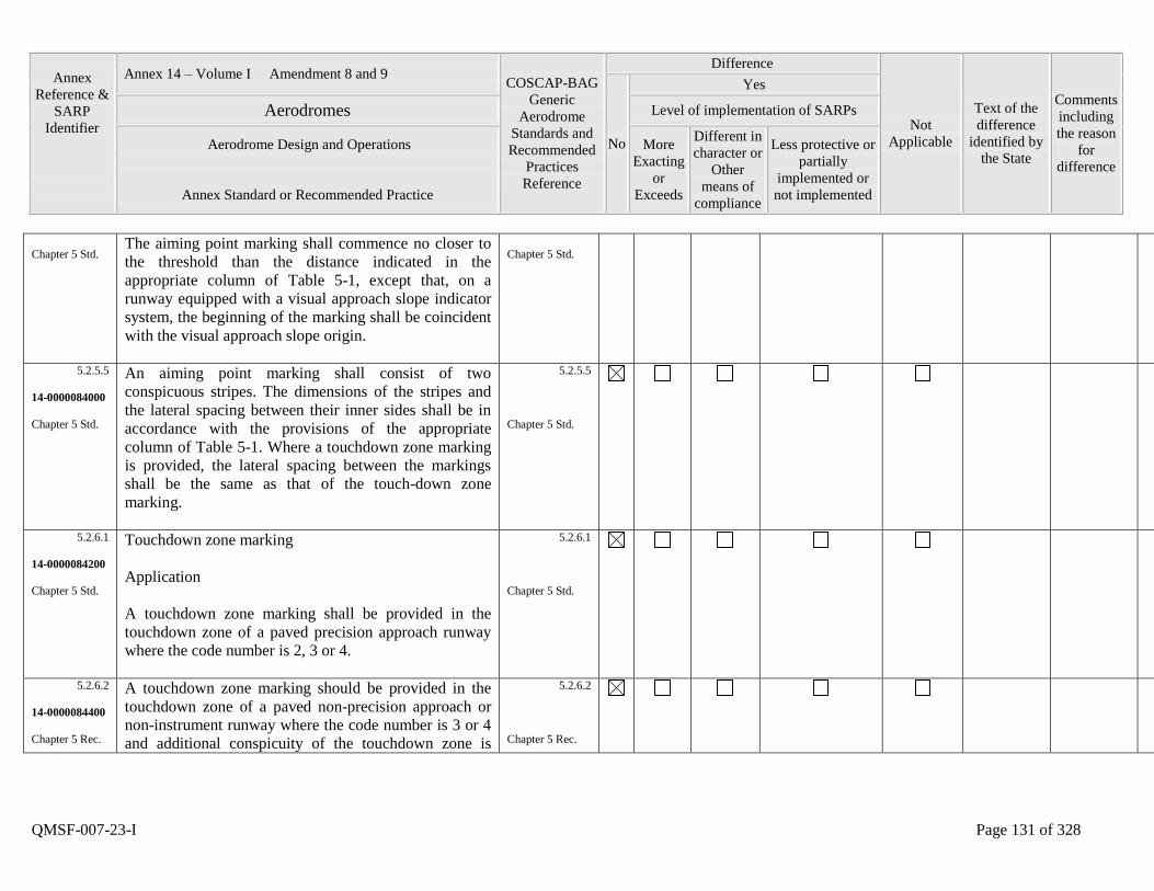
Annex
Reference &
SARP
Identifier
Annex 14 – Volume I Amendment 8 and 9 COSCAP-BAG
Generic
Aerodrome
Standards and
Recommended
Practices
Reference
Difference
Not
Applicable
Text of the
difference
identified by
the State
Comments
including
the reason
for
difference
No
Yes
Aerodromes Level of implementation of SARPs
Aerodrome Design and Operations
Annex Standard or Recommended Practice
More
Exacting
or
Exceeds
Different in
character or
Other
means of
compliance
Less protective or
partially
implemented or
not implemented
QMSF-007-23-I Page 131 of 328
Chapter 5 Std. The aiming point marking shall commence no closer to
the threshold than the distance indicated in the
appropriate column of Table 5-1, except that, on a
runway equipped with a visual approach slope indicator
system, the beginning of the marking shall be coincident
with the visual approach slope origin.
Chapter 5 Std.
5.2.5.5
14-0000084000
Chapter 5 Std.
An aiming point marking shall consist of two
conspicuous stripes. The dimensions of the stripes and
the lateral spacing between their inner sides shall be in
accordance with the provisions of the appropriate
column of Table 5-1. Where a touchdown zone marking
is provided, the lateral spacing between the markings
shall be the same as that of the touch-down zone
marking.
5.2.5.5
Chapter 5 Std.
5.2.6.1
14-0000084200
Chapter 5 Std.
Touchdown zone marking
Application
A touchdown zone marking shall be provided in the
touchdown zone of a paved precision approach runway
where the code number is 2, 3 or 4.
5.2.6.1
Chapter 5 Std.
5.2.6.2
14-0000084400
Chapter 5 Rec.
A touchdown zone marking should be provided in the
touchdown zone of a paved non-precision approach or
non-instrument runway where the code number is 3 or 4
and additional conspicuity of the touchdown zone is
5.2.6.2
Chapter 5 Rec.
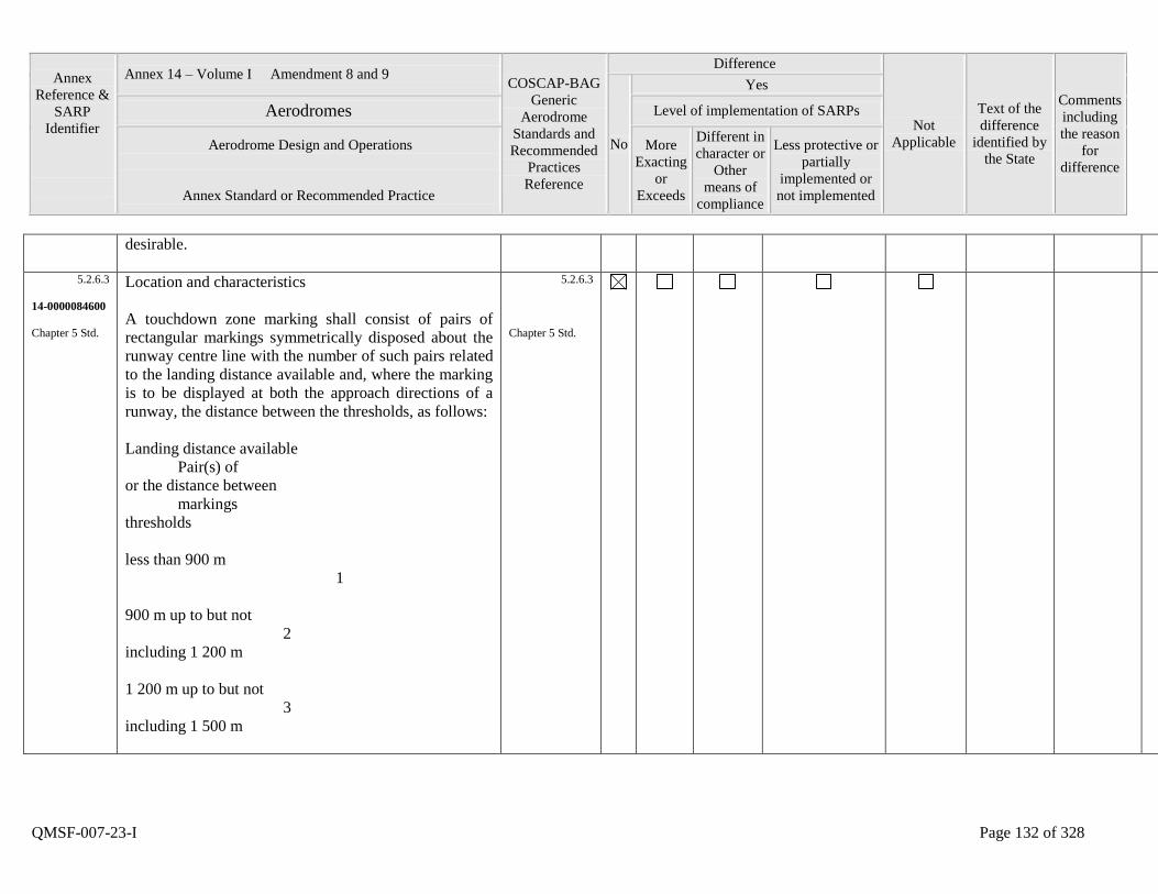
Annex
Reference &
SARP
Identifier
Annex 14 – Volume I Amendment 8 and 9 COSCAP-BAG
Generic
Aerodrome
Standards and
Recommended
Practices
Reference
Difference
Not
Applicable
Text of the
difference
identified by
the State
Comments
including
the reason
for
difference
No
Yes
Aerodromes Level of implementation of SARPs
Aerodrome Design and Operations
Annex Standard or Recommended Practice
More
Exacting
or
Exceeds
Different in
character or
Other
means of
compliance
Less protective or
partially
implemented or
not implemented
QMSF-007-23-I Page 132 of 328
desirable.
5.2.6.3
14-0000084600
Chapter 5 Std.
Location and characteristics
A touchdown zone marking shall consist of pairs of
rectangular markings symmetrically disposed about the
runway centre line with the number of such pairs related
to the landing distance available and, where the marking
is to be displayed at both the approach directions of a
runway, the distance between the thresholds, as follows:
Landing distance available
Pair(s) of
or the distance between
markings
thresholds
less than 900 m
1
900 m up to but not
2
including 1 200 m
1 200 m up to but not
3
including 1 500 m
5.2.6.3
Chapter 5 Std.
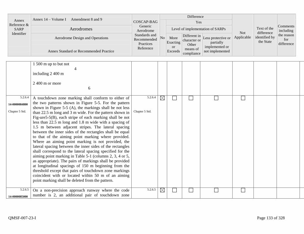
Annex
Reference &
SARP
Identifier
Annex 14 – Volume I Amendment 8 and 9 COSCAP-BAG
Generic
Aerodrome
Standards and
Recommended
Practices
Reference
Difference
Not
Applicable
Text of the
difference
identified by
the State
Comments
including
the reason
for
difference
No
Yes
Aerodromes Level of implementation of SARPs
Aerodrome Design and Operations
Annex Standard or Recommended Practice
More
Exacting
or
Exceeds
Different in
character or
Other
means of
compliance
Less protective or
partially
implemented or
not implemented
QMSF-007-23-I Page 133 of 328
1 500 m up to but not
4
including 2 400 m
2 400 m or more
6
5.2.6.4
14-0000084800
Chapter 5 Std.
A touchdown zone marking shall conform to either of
the two patterns shown in Figure 5-5. For the pattern
shown in Figure 5-5 (A), the markings shall be not less
than 22.5 m long and 3 m wide. For the pattern shown in
Fig-ure5-5(B), each stripe of each marking shall be not
less than 22.5 m long and 1.8 m wide with a spacing of
1.5 m between adjacent stripes. The lateral spacing
between the inner sides of the rectangles shall be equal
to that of the aiming point marking where provided.
Where an aiming point marking is not provided, the
lateral spacing between the inner sides of the rectangles
shall correspond to the lateral spacing specified for the
aiming point marking in Table 5-1 (columns 2, 3, 4 or 5,
as appropriate). The pairs of markings shall be provided
at longitudinal spacings of 150 m beginning from the
threshold except that pairs of touchdown zone markings
coincident with or located within 50 m of an aiming
point marking shall be deleted from the pattern.
5.2.6.4
Chapter 5 Std.
5.2.6.5
14-0000085000
On a non-precision approach runway where the code
number is 2, an additional pair of touchdown zone
5.2.6.5
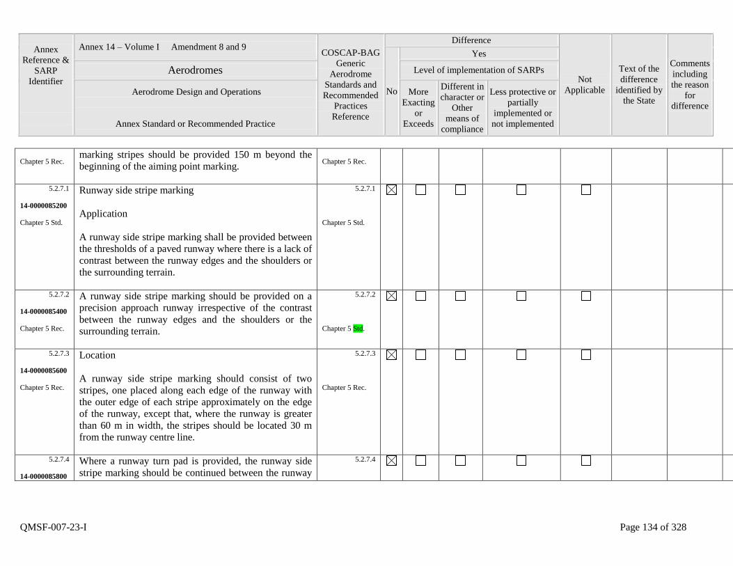
Annex
Reference &
SARP
Identifier
Annex 14 – Volume I Amendment 8 and 9 COSCAP-BAG
Generic
Aerodrome
Standards and
Recommended
Practices
Reference
Difference
Not
Applicable
Text of the
difference
identified by
the State
Comments
including
the reason
for
difference
No
Yes
Aerodromes Level of implementation of SARPs
Aerodrome Design and Operations
Annex Standard or Recommended Practice
More
Exacting
or
Exceeds
Different in
character or
Other
means of
compliance
Less protective or
partially
implemented or
not implemented
QMSF-007-23-I Page 134 of 328
Chapter 5 Rec. marking stripes should be provided 150 m beyond the
beginning of the aiming point marking.
Chapter 5 Rec.
5.2.7.1
14-0000085200
Chapter 5 Std.
Runway side stripe marking
Application
A runway side stripe marking shall be provided between
the thresholds of a paved runway where there is a lack of
contrast between the runway edges and the shoulders or
the surrounding terrain.
5.2.7.1
Chapter 5 Std.
5.2.7.2
14-0000085400
Chapter 5 Rec.
A runway side stripe marking should be provided on a
precision approach runway irrespective of the contrast
between the runway edges and the shoulders or the
surrounding terrain.
5.2.7.2
Chapter 5 Std.
5.2.7.3
14-0000085600
Chapter 5 Rec.
Location
A runway side stripe marking should consist of two
stripes, one placed along each edge of the runway with
the outer edge of each stripe approximately on the edge
of the runway, except that, where the runway is greater
than 60 m in width, the stripes should be located 30 m
from the runway centre line.
5.2.7.3
Chapter 5 Rec.
5.2.7.4
14-0000085800
Where a runway turn pad is provided, the runway side
stripe marking should be continued between the runway
5.2.7.4
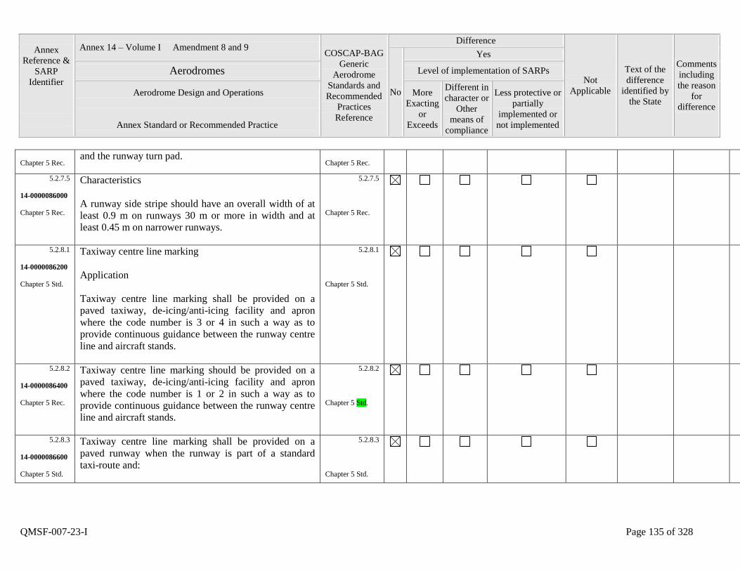
Annex
Reference &
SARP
Identifier
Annex 14 – Volume I Amendment 8 and 9 COSCAP-BAG
Generic
Aerodrome
Standards and
Recommended
Practices
Reference
Difference
Not
Applicable
Text of the
difference
identified by
the State
Comments
including
the reason
for
difference
No
Yes
Aerodromes Level of implementation of SARPs
Aerodrome Design and Operations
Annex Standard or Recommended Practice
More
Exacting
or
Exceeds
Different in
character or
Other
means of
compliance
Less protective or
partially
implemented or
not implemented
QMSF-007-23-I Page 135 of 328
Chapter 5 Rec. and the runway turn pad.
Chapter 5 Rec.
5.2.7.5
14-0000086000
Chapter 5 Rec.
Characteristics
A runway side stripe should have an overall width of at
least 0.9 m on runways 30 m or more in width and at
least 0.45 m on narrower runways.
5.2.7.5
Chapter 5 Rec.
5.2.8.1
14-0000086200
Chapter 5 Std.
Taxiway centre line marking
Application
Taxiway centre line marking shall be provided on a
paved taxiway, de-icing/anti-icing facility and apron
where the code number is 3 or 4 in such a way as to
provide continuous guidance between the runway centre
line and aircraft stands.
5.2.8.1
Chapter 5 Std.
5.2.8.2
14-0000086400
Chapter 5 Rec.
Taxiway centre line marking should be provided on a
paved taxiway, de-icing/anti-icing facility and apron
where the code number is 1 or 2 in such a way as to
provide continuous guidance between the runway centre
line and aircraft stands.
5.2.8.2
Chapter 5 Std.
5.2.8.3
14-0000086600
Chapter 5 Std.
Taxiway centre line marking shall be provided on a
paved runway when the runway is part of a standard
taxi-route and:
5.2.8.3
Chapter 5 Std.
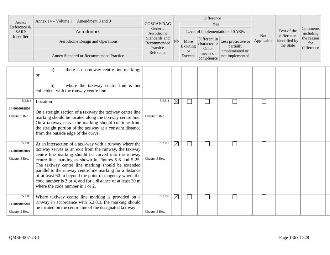
Annex
Reference &
SARP
Identifier
Annex 14 – Volume I Amendment 8 and 9 COSCAP-BAG
Generic
Aerodrome
Standards and
Recommended
Practices
Reference
Difference
Not
Applicable
Text of the
difference
identified by
the State
Comments
including
the reason
for
difference
No
Yes
Aerodromes Level of implementation of SARPs
Aerodrome Design and Operations
Annex Standard or Recommended Practice
More
Exacting
or
Exceeds
Different in
character or
Other
means of
compliance
Less protective or
partially
implemented or
not implemented
QMSF-007-23-I Page 136 of 328
a) there is no runway centre line marking;
or
b) where the taxiway centre line is not
coincident with the runway centre line.
5.2.8.4
14-0000086800
Chapter 5 Rec.
Location
On a straight section of a taxiway the taxiway centre line
marking should be located along the taxiway centre line.
On a taxiway curve the marking should continue from
the straight portion of the taxiway at a constant distance
from the outside edge of the curve.
5.2.8.4
Chapter 5 Rec.
5.2.8.5
14-0000087000
Chapter 5 Rec.
At an intersection of a taxi-way with a runway where the
taxiway serves as an exit from the runway, the taxiway
centre line marking should be curved into the runway
centre line marking as shown in Figures 5-6 and 5-25.
The taxiway centre line marking should be extended
parallel to the runway centre line marking for a distance
of at least 60 m beyond the point of tangency where the
code number is 3 or 4, and for a distance of at least 30 m
where the code number is 1 or 2.
5.2.8.5
Chapter 5 Rec.
5.2.8.6
14-0000087200
Chapter 5 Rec.
Where taxiway centre line marking is provided on a
runway in accordance with 5.2.8.3, the marking should
be located on the centre line of the designated taxiway.
5.2.8.6
Chapter 5 Rec.
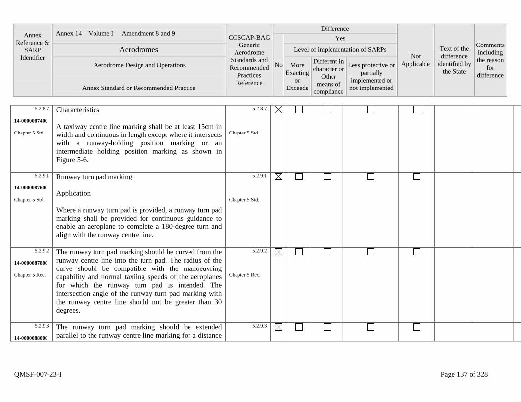
Annex
Reference &
SARP
Identifier
Annex 14 – Volume I Amendment 8 and 9 COSCAP-BAG
Generic
Aerodrome
Standards and
Recommended
Practices
Reference
Difference
Not
Applicable
Text of the
difference
identified by
the State
Comments
including
the reason
for
difference
No
Yes
Aerodromes Level of implementation of SARPs
Aerodrome Design and Operations
Annex Standard or Recommended Practice
More
Exacting
or
Exceeds
Different in
character or
Other
means of
compliance
Less protective or
partially
implemented or
not implemented
QMSF-007-23-I Page 137 of 328
5.2.8.7
14-0000087400
Chapter 5 Std.
Characteristics
A taxiway centre line marking shall be at least 15cm in
width and continuous in length except where it intersects
with a runway-holding position marking or an
intermediate holding position marking as shown in
Figure 5-6.
5.2.8.7
Chapter 5 Std.
5.2.9.1
14-0000087600
Chapter 5 Std.
Runway turn pad marking
Application
Where a runway turn pad is provided, a runway turn pad
marking shall be provided for continuous guidance to
enable an aeroplane to complete a 180-degree turn and
align with the runway centre line.
5.2.9.1
Chapter 5 Std.
5.2.9.2
14-0000087800
Chapter 5 Rec.
The runway turn pad marking should be curved from the
runway centre line into the turn pad. The radius of the
curve should be compatible with the manoeuvring
capability and normal taxiing speeds of the aeroplanes
for which the runway turn pad is intended. The
intersection angle of the runway turn pad marking with
the runway centre line should not be greater than 30
degrees.
5.2.9.2
Chapter 5 Rec.
5.2.9.3
14-0000088000
The runway turn pad marking should be extended
parallel to the runway centre line marking for a distance
5.2.9.3
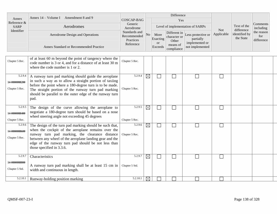
Annex
Reference &
SARP
Identifier
Annex 14 – Volume I Amendment 8 and 9 COSCAP-BAG
Generic
Aerodrome
Standards and
Recommended
Practices
Reference
Difference
Not
Applicable
Text of the
difference
identified by
the State
Comments
including
the reason
for
difference
No
Yes
Aerodromes Level of implementation of SARPs
Aerodrome Design and Operations
Annex Standard or Recommended Practice
More
Exacting
or
Exceeds
Different in
character or
Other
means of
compliance
Less protective or
partially
implemented or
not implemented
QMSF-007-23-I Page 138 of 328
Chapter 5 Rec. of at least 60 m beyond the point of tangency where the
code number is 3 or 4, and for a distance of at least 30 m
where the code number is 1 or 2.
Chapter 5 Rec.
5.2.9.4
14-0000088200
Chapter 5 Rec.
A runway turn pad marking should guide the aeroplane
in such a way as to allow a straight portion of taxiing
before the point where a 180-degree turn is to be made.
The straight portion of the runway turn pad marking
should be parallel to the outer edge of the runway turn
pad.
5.2.9.4
Chapter 5 Rec.
5.2.9.5
14-0000088400
Chapter 5 Rec.
The design of the curve allowing the aeroplane to
negotiate a 180-degree turn should be based on a nose
wheel steering angle not exceeding 45 degrees
5.2.9.5
Chapter 5 Rec.
5.2.9.6
14-0000088600
Chapter 5 Rec.
The design of the turn pad marking should be such that,
when the cockpit of the aeroplane remains over the
runway turn pad marking, the clearance distance
between any wheel of the aeroplane landing gear and the
edge of the runway turn pad should be not less than
those specified in 3.3.6.
5.2.9.6
Chapter 5 Rec.
5.2.9.7
14-0000088800
Chapter 5 Std.
Characteristics
A runway turn pad marking shall be at least 15 cm in
width and continuous in length.
5.2.9.7
Chapter 5 Std.
5.2.10.1 Runway-holding position marking 5.2.10.1
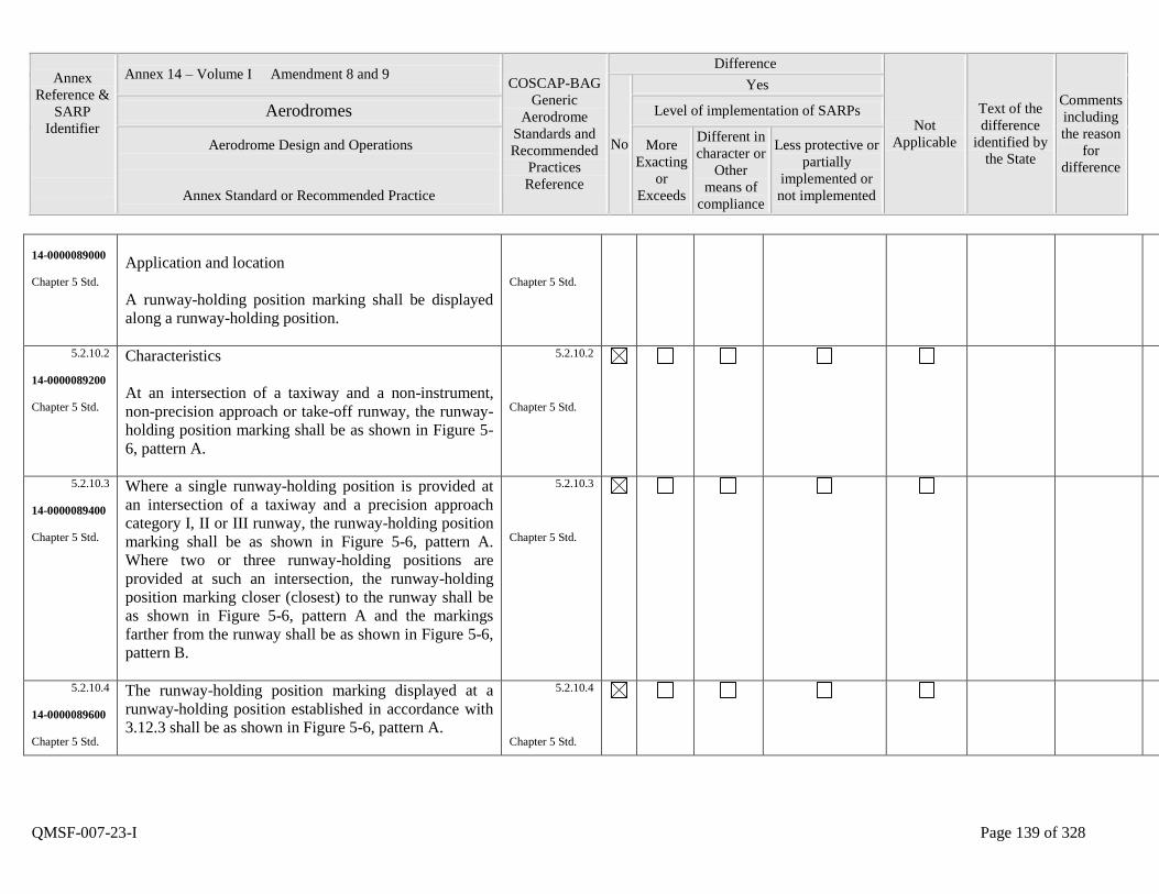
Annex
Reference &
SARP
Identifier
Annex 14 – Volume I Amendment 8 and 9 COSCAP-BAG
Generic
Aerodrome
Standards and
Recommended
Practices
Reference
Difference
Not
Applicable
Text of the
difference
identified by
the State
Comments
including
the reason
for
difference
No
Yes
Aerodromes Level of implementation of SARPs
Aerodrome Design and Operations
Annex Standard or Recommended Practice
More
Exacting
or
Exceeds
Different in
character or
Other
means of
compliance
Less protective or
partially
implemented or
not implemented
QMSF-007-23-I Page 139 of 328
14-0000089000
Chapter 5 Std.
Application and location
A runway-holding position marking shall be displayed
along a runway-holding position.
Chapter 5 Std.
5.2.10.2
14-0000089200
Chapter 5 Std.
Characteristics
At an intersection of a taxiway and a non-instrument,
non-precision approach or take-off runway, the runway-
holding position marking shall be as shown in Figure 5-
6, pattern A.
5.2.10.2
Chapter 5 Std.
5.2.10.3
14-0000089400
Chapter 5 Std.
Where a single runway-holding position is provided at
an intersection of a taxiway and a precision approach
category I, II or III runway, the runway-holding position
marking shall be as shown in Figure 5-6, pattern A.
Where two or three runway-holding positions are
provided at such an intersection, the runway-holding
position marking closer (closest) to the runway shall be
as shown in Figure 5-6, pattern A and the markings
farther from the runway shall be as shown in Figure 5-6,
pattern B.
5.2.10.3
Chapter 5 Std.
5.2.10.4
14-0000089600
Chapter 5 Std.
The runway-holding position marking displayed at a
runway-holding position established in accordance with
3.12.3 shall be as shown in Figure 5-6, pattern A.
5.2.10.4
Chapter 5 Std.
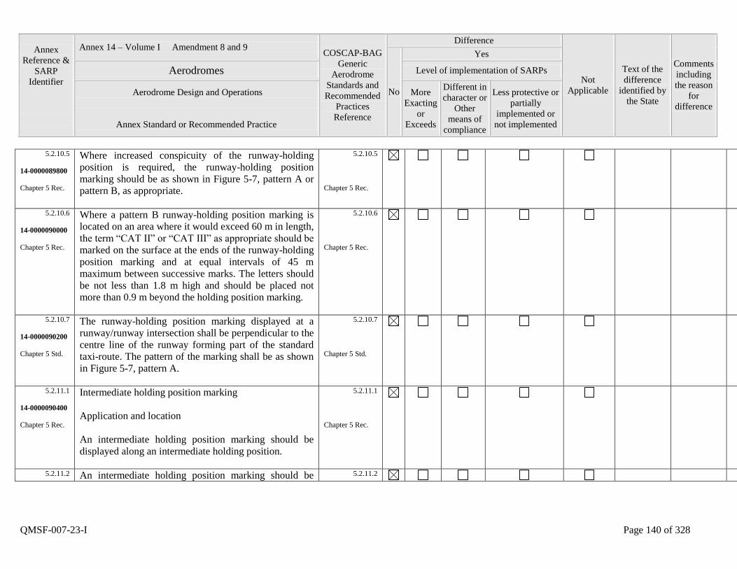
Annex
Reference &
SARP
Identifier
Annex 14 – Volume I Amendment 8 and 9 COSCAP-BAG
Generic
Aerodrome
Standards and
Recommended
Practices
Reference
Difference
Not
Applicable
Text of the
difference
identified by
the State
Comments
including
the reason
for
difference
No
Yes
Aerodromes Level of implementation of SARPs
Aerodrome Design and Operations
Annex Standard or Recommended Practice
More
Exacting
or
Exceeds
Different in
character or
Other
means of
compliance
Less protective or
partially
implemented or
not implemented
QMSF-007-23-I Page 140 of 328
5.2.10.5
14-0000089800
Chapter 5 Rec.
Where increased conspicuity of the runway-holding
position is required, the runway-holding position
marking should be as shown in Figure 5-7, pattern A or
pattern B, as appropriate.
5.2.10.5
Chapter 5 Rec.
5.2.10.6
14-0000090000
Chapter 5 Rec.
Where a pattern B runway-holding position marking is
located on an area where it would exceed 60 m in length,
the term “CAT II” or “CAT III” as appropriate should be
marked on the surface at the ends of the runway-holding
position marking and at equal intervals of 45 m
maximum between successive marks. The letters should
be not less than 1.8 m high and should be placed not
more than 0.9 m beyond the holding position marking.
5.2.10.6
Chapter 5 Rec.
5.2.10.7
14-0000090200
Chapter 5 Std.
The runway-holding position marking displayed at a
runway/runway intersection shall be perpendicular to the
centre line of the runway forming part of the standard
taxi-route. The pattern of the marking shall be as shown
in Figure 5-7, pattern A.
5.2.10.7
Chapter 5 Std.
5.2.11.1
14-0000090400
Chapter 5 Rec.
Intermediate holding position marking
Application and location
An intermediate holding position marking should be
displayed along an intermediate holding position.
5.2.11.1
Chapter 5 Rec.
5.2.11.2 An intermediate holding position marking should be 5.2.11.2
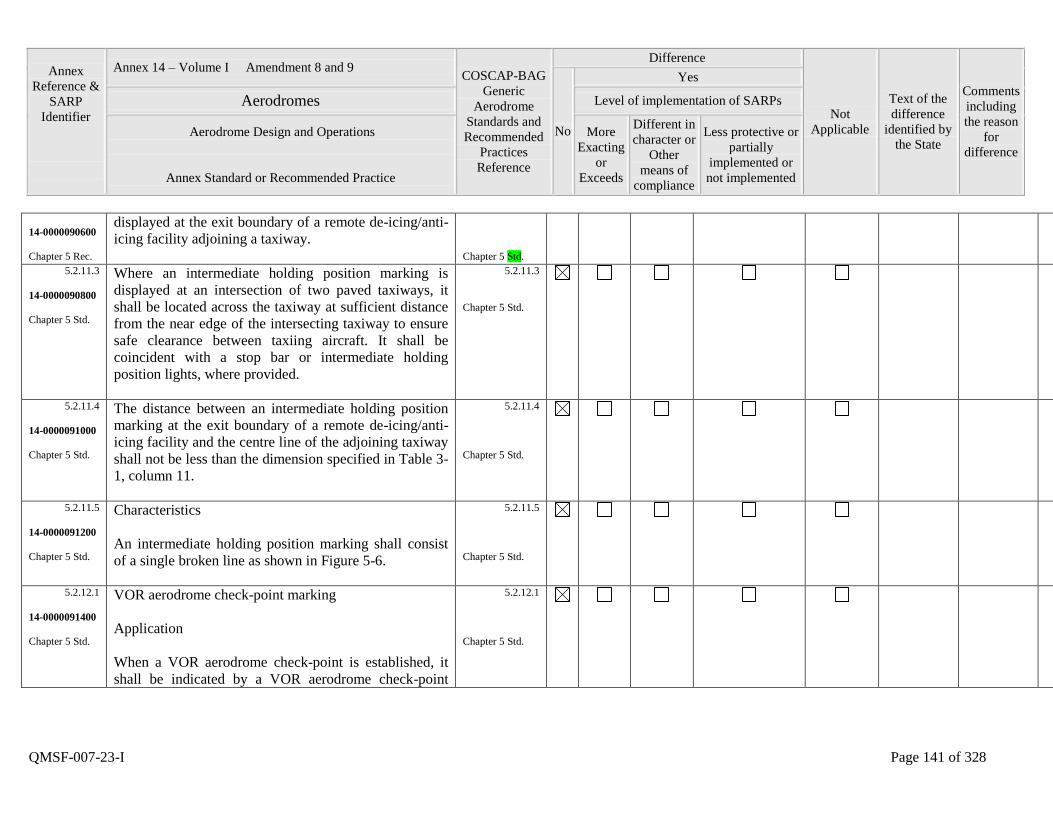
Annex
Reference &
SARP
Identifier
Annex 14 – Volume I Amendment 8 and 9 COSCAP-BAG
Generic
Aerodrome
Standards and
Recommended
Practices
Reference
Difference
Not
Applicable
Text of the
difference
identified by
the State
Comments
including
the reason
for
difference
No
Yes
Aerodromes Level of implementation of SARPs
Aerodrome Design and Operations
Annex Standard or Recommended Practice
More
Exacting
or
Exceeds
Different in
character or
Other
means of
compliance
Less protective or
partially
implemented or
not implemented
QMSF-007-23-I Page 141 of 328
14-0000090600
Chapter 5 Rec.
displayed at the exit boundary of a remote de-icing/anti-
icing facility adjoining a taxiway.
Chapter 5 Std.
5.2.11.3
14-0000090800
Chapter 5 Std.
Where an intermediate holding position marking is
displayed at an intersection of two paved taxiways, it
shall be located across the taxiway at sufficient distance
from the near edge of the intersecting taxiway to ensure
safe clearance between taxiing aircraft. It shall be
coincident with a stop bar or intermediate holding
position lights, where provided.
5.2.11.3
Chapter 5 Std.
5.2.11.4
14-0000091000
Chapter 5 Std.
The distance between an intermediate holding position
marking at the exit boundary of a remote de-icing/anti-
icing facility and the centre line of the adjoining taxiway
shall not be less than the dimension specified in Table 3-
1, column 11.
5.2.11.4
Chapter 5 Std.
5.2.11.5
14-0000091200
Chapter 5 Std.
Characteristics
An intermediate holding position marking shall consist
of a single broken line as shown in Figure 5-6.
5.2.11.5
Chapter 5 Std.
5.2.12.1
14-0000091400
Chapter 5 Std.
VOR aerodrome check-point marking
Application
When a VOR aerodrome check-point is established, it
shall be indicated by a VOR aerodrome check-point
5.2.12.1
Chapter 5 Std.
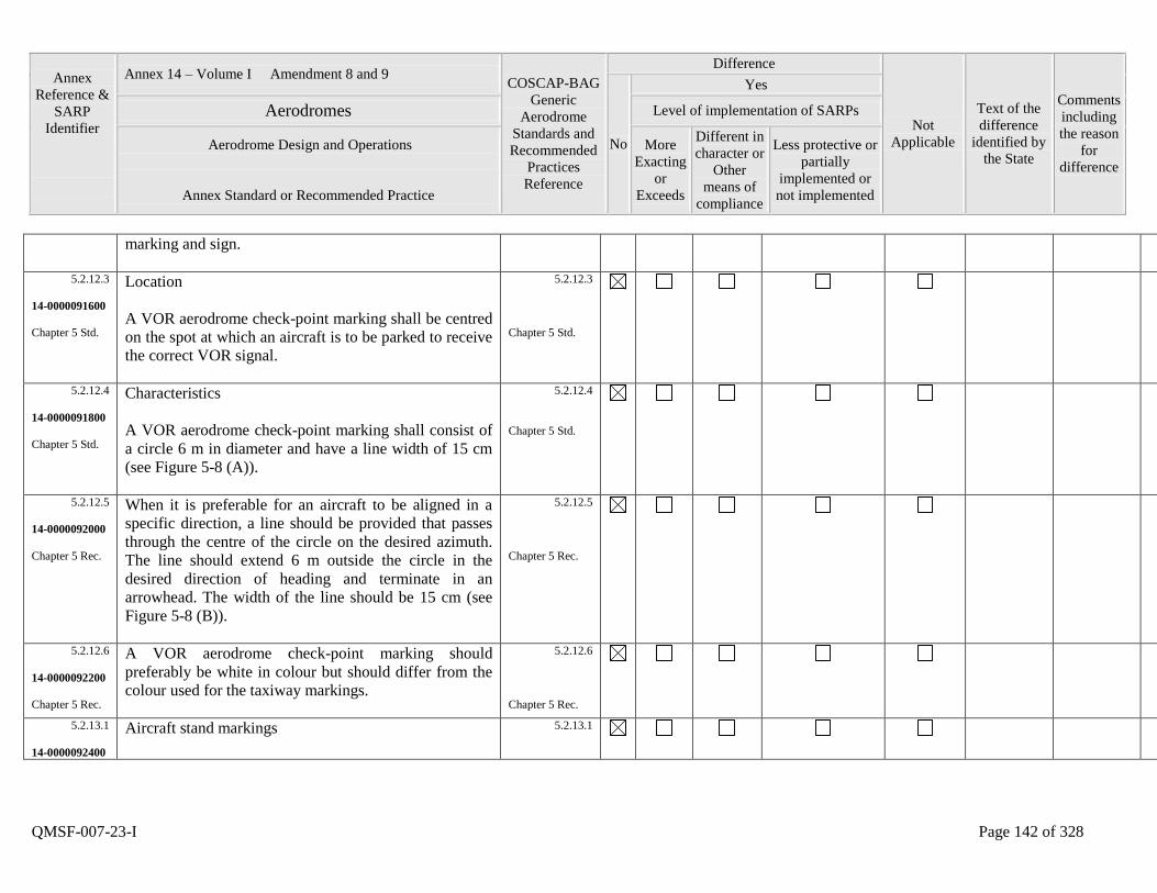
Annex
Reference &
SARP
Identifier
Annex 14 – Volume I Amendment 8 and 9 COSCAP-BAG
Generic
Aerodrome
Standards and
Recommended
Practices
Reference
Difference
Not
Applicable
Text of the
difference
identified by
the State
Comments
including
the reason
for
difference
No
Yes
Aerodromes Level of implementation of SARPs
Aerodrome Design and Operations
Annex Standard or Recommended Practice
More
Exacting
or
Exceeds
Different in
character or
Other
means of
compliance
Less protective or
partially
implemented or
not implemented
QMSF-007-23-I Page 142 of 328
marking and sign.
5.2.12.3
14-0000091600
Chapter 5 Std.
Location
A VOR aerodrome check-point marking shall be centred
on the spot at which an aircraft is to be parked to receive
the correct VOR signal.
5.2.12.3
Chapter 5 Std.
5.2.12.4
14-0000091800
Chapter 5 Std.
Characteristics
A VOR aerodrome check-point marking shall consist of
a circle 6 m in diameter and have a line width of 15 cm
(see Figure 5-8 (A)).
5.2.12.4
Chapter 5 Std.
5.2.12.5
14-0000092000
Chapter 5 Rec.
When it is preferable for an aircraft to be aligned in a
specific direction, a line should be provided that passes
through the centre of the circle on the desired azimuth.
The line should extend 6 m outside the circle in the
desired direction of heading and terminate in an
arrowhead. The width of the line should be 15 cm (see
Figure 5-8 (B)).
5.2.12.5
Chapter 5 Rec.
5.2.12.6
14-0000092200
Chapter 5 Rec.
A VOR aerodrome check-point marking should
preferably be white in colour but should differ from the
colour used for the taxiway markings.
5.2.12.6
Chapter 5 Rec.
5.2.13.1
14-0000092400
Aircraft stand markings
5.2.13.1
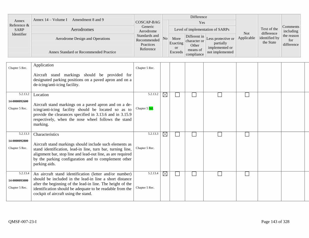
Annex
Reference &
SARP
Identifier
Annex 14 – Volume I Amendment 8 and 9 COSCAP-BAG
Generic
Aerodrome
Standards and
Recommended
Practices
Reference
Difference
Not
Applicable
Text of the
difference
identified by
the State
Comments
including
the reason
for
difference
No
Yes
Aerodromes Level of implementation of SARPs
Aerodrome Design and Operations
Annex Standard or Recommended Practice
More
Exacting
or
Exceeds
Different in
character or
Other
means of
compliance
Less protective or
partially
implemented or
not implemented
QMSF-007-23-I Page 143 of 328
Chapter 5 Rec. Application
Aircraft stand markings should be provided for
designated parking positions on a paved apron and on a
de-icing/anti-icing facility.
Chapter 5 Rec.
5.2.13.2
14-0000092600
Chapter 5 Rec.
Location
Aircraft stand markings on a paved apron and on a de-
icing/anti-icing facility should be located so as to
provide the clearances specified in 3.13.6 and in 3.15.9
respectively, when the nose wheel follows the stand
marking.
5.2.13.2
Chapter 5 Std.
5.2.13.3
14-0000092800
Chapter 5 Rec.
Characteristics
Aircraft stand markings should include such elements as
stand identification, lead-in line, turn bar, turning line,
alignment bar, stop line and lead-out line, as are required
by the parking configuration and to complement other
parking aids.
5.2.13.3
Chapter 5 Rec.
5.2.13.4
14-0000093000
Chapter 5 Rec.
An aircraft stand identification (letter and/or number)
should be included in the lead-in line a short distance
after the beginning of the lead-in line. The height of the
identification should be adequate to be readable from the
cockpit of aircraft using the stand.
5.2.13.4
Chapter 5 Rec.
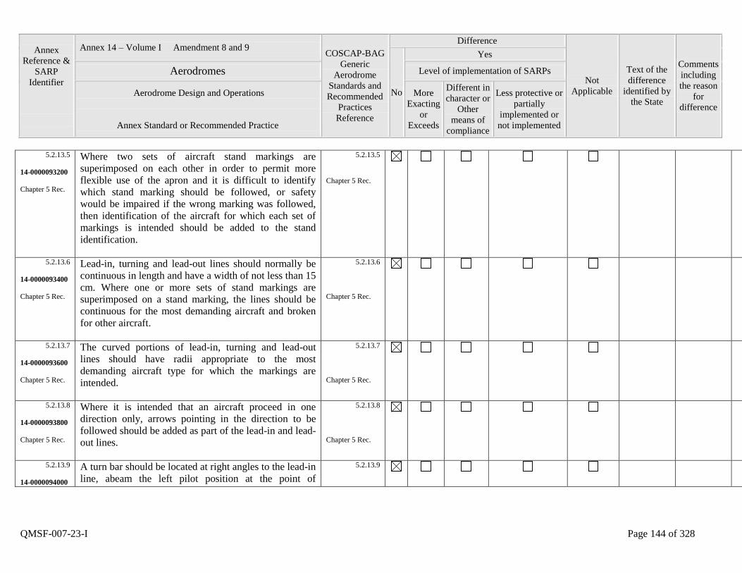
Annex
Reference &
SARP
Identifier
Annex 14 – Volume I Amendment 8 and 9 COSCAP-BAG
Generic
Aerodrome
Standards and
Recommended
Practices
Reference
Difference
Not
Applicable
Text of the
difference
identified by
the State
Comments
including
the reason
for
difference
No
Yes
Aerodromes Level of implementation of SARPs
Aerodrome Design and Operations
Annex Standard or Recommended Practice
More
Exacting
or
Exceeds
Different in
character or
Other
means of
compliance
Less protective or
partially
implemented or
not implemented
QMSF-007-23-I Page 144 of 328
5.2.13.5
14-0000093200
Chapter 5 Rec.
Where two sets of aircraft stand markings are
superimposed on each other in order to permit more
flexible use of the apron and it is difficult to identify
which stand marking should be followed, or safety
would be impaired if the wrong marking was followed,
then identification of the aircraft for which each set of
markings is intended should be added to the stand
identification.
5.2.13.5
Chapter 5 Rec.
5.2.13.6
14-0000093400
Chapter 5 Rec.
Lead-in, turning and lead-out lines should normally be
continuous in length and have a width of not less than 15
cm. Where one or more sets of stand markings are
superimposed on a stand marking, the lines should be
continuous for the most demanding aircraft and broken
for other aircraft.
5.2.13.6
Chapter 5 Rec.
5.2.13.7
14-0000093600
Chapter 5 Rec.
The curved portions of lead-in, turning and lead-out
lines should have radii appropriate to the most
demanding aircraft type for which the markings are
intended.
5.2.13.7
Chapter 5 Rec.
5.2.13.8
14-0000093800
Chapter 5 Rec.
Where it is intended that an aircraft proceed in one
direction only, arrows pointing in the direction to be
followed should be added as part of the lead-in and lead-
out lines.
5.2.13.8
Chapter 5 Rec.
5.2.13.9
14-0000094000
A turn bar should be located at right angles to the lead-in
line, abeam the left pilot position at the point of
5.2.13.9
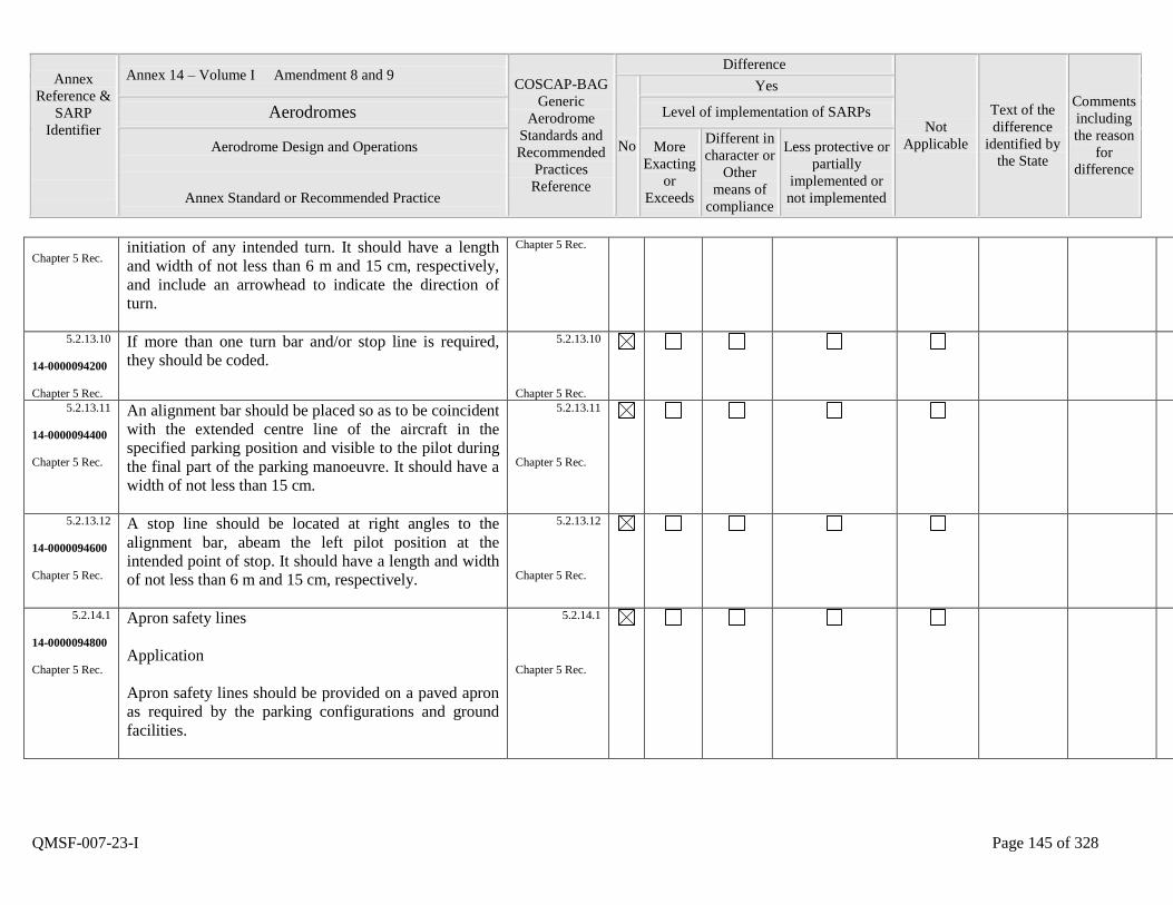
Annex
Reference &
SARP
Identifier
Annex 14 – Volume I Amendment 8 and 9 COSCAP-BAG
Generic
Aerodrome
Standards and
Recommended
Practices
Reference
Difference
Not
Applicable
Text of the
difference
identified by
the State
Comments
including
the reason
for
difference
No
Yes
Aerodromes Level of implementation of SARPs
Aerodrome Design and Operations
Annex Standard or Recommended Practice
More
Exacting
or
Exceeds
Different in
character or
Other
means of
compliance
Less protective or
partially
implemented or
not implemented
QMSF-007-23-I Page 145 of 328
Chapter 5 Rec. initiation of any intended turn. It should have a length
and width of not less than 6 m and 15 cm, respectively,
and include an arrowhead to indicate the direction of
turn.
Chapter 5 Rec.
5.2.13.10
14-0000094200
Chapter 5 Rec.
If more than one turn bar and/or stop line is required,
they should be coded.
5.2.13.10
Chapter 5 Rec.
5.2.13.11
14-0000094400
Chapter 5 Rec.
An alignment bar should be placed so as to be coincident
with the extended centre line of the aircraft in the
specified parking position and visible to the pilot during
the final part of the parking manoeuvre. It should have a
width of not less than 15 cm.
5.2.13.11
Chapter 5 Rec.
5.2.13.12
14-0000094600
Chapter 5 Rec.
A stop line should be located at right angles to the
alignment bar, abeam the left pilot position at the
intended point of stop. It should have a length and width
of not less than 6 m and 15 cm, respectively.
5.2.13.12
Chapter 5 Rec.
5.2.14.1
14-0000094800
Chapter 5 Rec.
Apron safety lines
Application
Apron safety lines should be provided on a paved apron
as required by the parking configurations and ground
facilities.
5.2.14.1
Chapter 5 Rec.
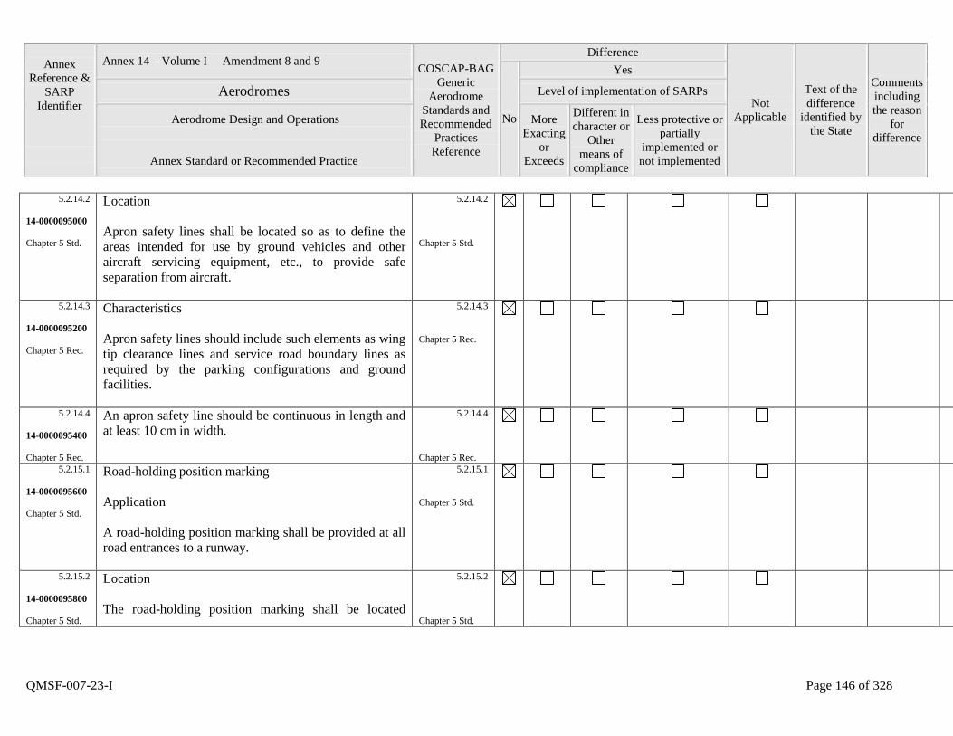
Annex
Reference &
SARP
Identifier
Annex 14 – Volume I Amendment 8 and 9 COSCAP-BAG
Generic
Aerodrome
Standards and
Recommended
Practices
Reference
Difference
Not
Applicable
Text of the
difference
identified by
the State
Comments
including
the reason
for
difference
No
Yes
Aerodromes Level of implementation of SARPs
Aerodrome Design and Operations
Annex Standard or Recommended Practice
More
Exacting
or
Exceeds
Different in
character or
Other
means of
compliance
Less protective or
partially
implemented or
not implemented
QMSF-007-23-I Page 146 of 328
5.2.14.2
14-0000095000
Chapter 5 Std.
Location
Apron safety lines shall be located so as to define the
areas intended for use by ground vehicles and other
aircraft servicing equipment, etc., to provide safe
separation from aircraft.
5.2.14.2
Chapter 5 Std.
5.2.14.3
14-0000095200
Chapter 5 Rec.
Characteristics
Apron safety lines should include such elements as wing
tip clearance lines and service road boundary lines as
required by the parking configurations and ground
facilities.
5.2.14.3
Chapter 5 Rec.
5.2.14.4
14-0000095400
Chapter 5 Rec.
An apron safety line should be continuous in length and
at least 10 cm in width.
5.2.14.4
Chapter 5 Rec.
5.2.15.1
14-0000095600
Chapter 5 Std.
Road-holding position marking
Application
A road-holding position marking shall be provided at all
road entrances to a runway.
5.2.15.1
Chapter 5 Std.
5.2.15.2
14-0000095800
Chapter 5 Std.
Location
The road-holding position marking shall be located
5.2.15.2
Chapter 5 Std.

Annex
Reference &
SARP
Identifier
Annex 14 – Volume I Amendment 8 and 9 COSCAP-BAG
Generic
Aerodrome
Standards and
Recommended
Practices
Reference
Difference
Not
Applicable
Text of the
difference
identified by
the State
Comments
including
the reason
for
difference
No
Yes
Aerodromes Level of implementation of SARPs
Aerodrome Design and Operations
Annex Standard or Recommended Practice
More
Exacting
or
Exceeds
Different in
character or
Other
means of
compliance
Less protective or
partially
implemented or
not implemented
QMSF-007-23-I Page 147 of 328
across the road at the holding position.
5.2.15.3
14-0000096000
Chapter 5 Std.
Characteristics
The road-holding position marking shall be in
accordance with the local road traffic regulations.
5.2.15.3
Chapter 5 Std.
5.2.16.1
14-0000096200
Chapter 5 Std.
Mandatory instruction marking
Application
Where it is impracticable to install a mandatory
instruction sign in accordance with 5.4.2.1, a mandatory
instruction marking shall be provided on the surface of
the pavement.
5.2.16.1
Chapter 5 Std.
5.2.16.2
14-0000096400
Chapter 5 Rec.
Where operationally required, such as on taxiways
exceeding 60 m in width, a mandatory instruction sign
should be supplemented by a mandatory instruction
marking.
5.2.16.2
Chapter 5 Rec.
5.2.16.3
14-0000096600
Chapter 5 Std.
Location
The mandatory instruction marking shall be located on
the left-hand side of the taxiway centre line marking and
on the holding side of the runway-holding position
marking as shown in Figure 5-9. The distance between
the nearest edge of the marking and the runway-holding
5.2.16.3
Chapter 5 Std.
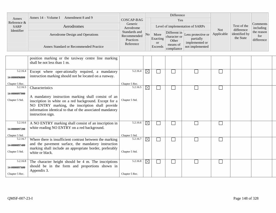
Annex
Reference &
SARP
Identifier
Annex 14 – Volume I Amendment 8 and 9 COSCAP-BAG
Generic
Aerodrome
Standards and
Recommended
Practices
Reference
Difference
Not
Applicable
Text of the
difference
identified by
the State
Comments
including
the reason
for
difference
No
Yes
Aerodromes Level of implementation of SARPs
Aerodrome Design and Operations
Annex Standard or Recommended Practice
More
Exacting
or
Exceeds
Different in
character or
Other
means of
compliance
Less protective or
partially
implemented or
not implemented
QMSF-007-23-I Page 148 of 328
position marking or the taxiway centre line marking
shall be not less than 1 m.
5.2.16.4
14-0000096800
Chapter 5 Rec.
Except where oper-ationally required, a mandatory
instruction marking should not be located on a runway.
5.2.16.4
Chapter 5 Rec.
5.2.16.5
14-0000097000
Chapter 5 Std.
Characteristics
A mandatory instruction marking shall consist of an
inscription in white on a red background. Except for a
NO ENTRY marking, the inscription shall provide
information identical to that of the associated mandatory
instruction sign.
5.2.16.5
Chapter 5 Std.
5.2.16.6
14-0000097200
Chapter 5 Std.
A NO ENTRY marking shall consist of an inscription in
white reading NO ENTRY on a red background.
5.2.16.6
Chapter 5 Std.
5.2.16.7
14-0000097400
Chapter 5 Std.
Where there is insufficient contrast between the marking
and the pavement surface, the mandatory instruction
marking shall include an appropriate border, preferably
white or black.
5.2.16.7
Chapter 5 Std.
5.2.16.8
14-0000097600
Chapter 5 Rec.
The character height should be 4 m. The inscriptions
should be in the form and proportions shown in
Appendix 3.
5.2.16.8
Chapter 5 Rec.
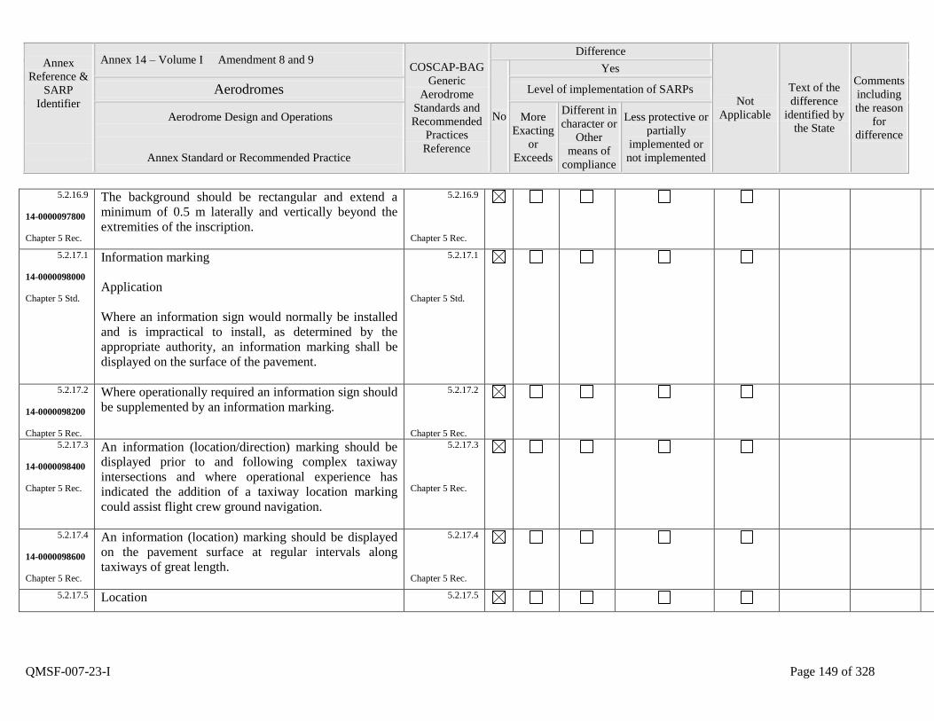
Annex
Reference &
SARP
Identifier
Annex 14 – Volume I Amendment 8 and 9 COSCAP-BAG
Generic
Aerodrome
Standards and
Recommended
Practices
Reference
Difference
Not
Applicable
Text of the
difference
identified by
the State
Comments
including
the reason
for
difference
No
Yes
Aerodromes Level of implementation of SARPs
Aerodrome Design and Operations
Annex Standard or Recommended Practice
More
Exacting
or
Exceeds
Different in
character or
Other
means of
compliance
Less protective or
partially
implemented or
not implemented
QMSF-007-23-I Page 149 of 328
5.2.16.9
14-0000097800
Chapter 5 Rec.
The background should be rectangular and extend a
minimum of 0.5 m laterally and vertically beyond the
extremities of the inscription.
5.2.16.9
Chapter 5 Rec.
5.2.17.1
14-0000098000
Chapter 5 Std.
Information marking
Application
Where an information sign would normally be installed
and is impractical to install, as determined by the
appropriate authority, an information marking shall be
displayed on the surface of the pavement.
5.2.17.1
Chapter 5 Std.
5.2.17.2
14-0000098200
Chapter 5 Rec.
Where operationally required an information sign should
be supplemented by an information marking.
5.2.17.2
Chapter 5 Rec.
5.2.17.3
14-0000098400
Chapter 5 Rec.
An information (location/direction) marking should be
displayed prior to and following complex taxiway
intersections and where operational experience has
indicated the addition of a taxiway location marking
could assist flight crew ground navigation.
5.2.17.3
Chapter 5 Rec.
5.2.17.4
14-0000098600
Chapter 5 Rec.
An information (location) marking should be displayed
on the pavement surface at regular intervals along
taxiways of great length.
5.2.17.4
Chapter 5 Rec.
5.2.17.5
Location 5.2.17.5
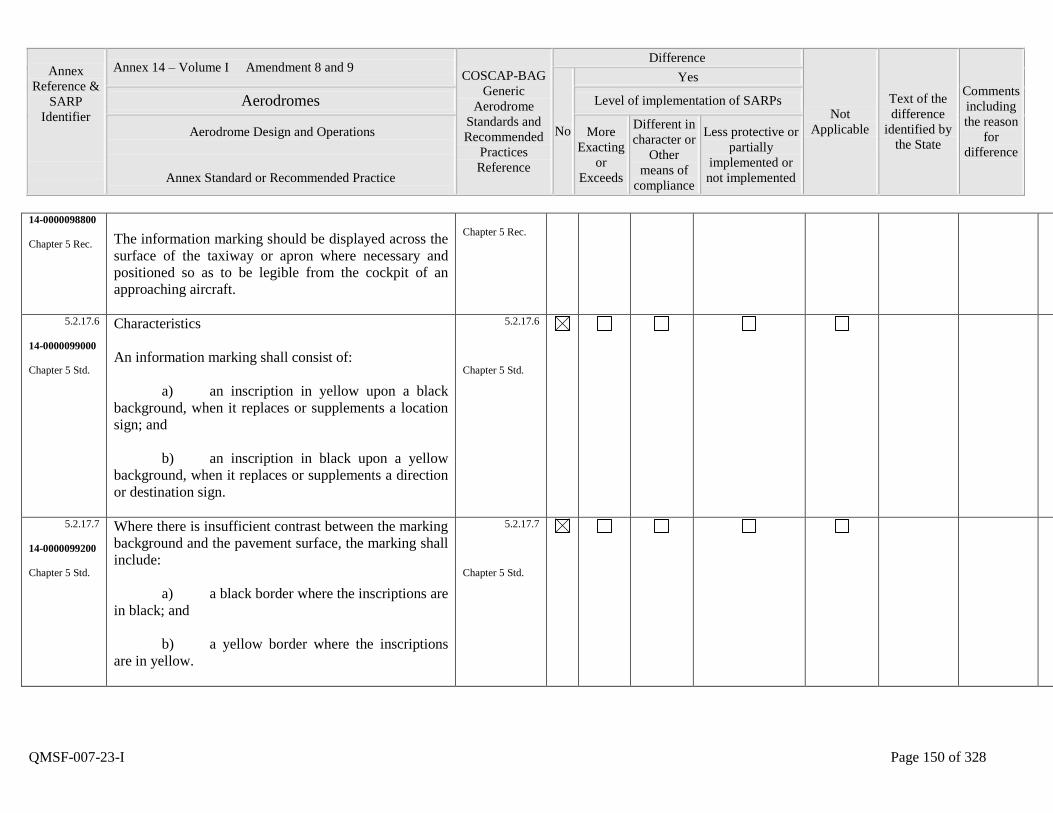
Annex
Reference &
SARP
Identifier
Annex 14 – Volume I Amendment 8 and 9 COSCAP-BAG
Generic
Aerodrome
Standards and
Recommended
Practices
Reference
Difference
Not
Applicable
Text of the
difference
identified by
the State
Comments
including
the reason
for
difference
No
Yes
Aerodromes Level of implementation of SARPs
Aerodrome Design and Operations
Annex Standard or Recommended Practice
More
Exacting
or
Exceeds
Different in
character or
Other
means of
compliance
Less protective or
partially
implemented or
not implemented
QMSF-007-23-I Page 150 of 328
14-0000098800
Chapter 5 Rec.
The information marking should be displayed across the
surface of the taxiway or apron where necessary and
positioned so as to be legible from the cockpit of an
approaching aircraft.
Chapter 5 Rec.
5.2.17.6
14-0000099000
Chapter 5 Std.
Characteristics
An information marking shall consist of:
a) an inscription in yellow upon a black
background, when it replaces or supplements a location
sign; and
b) an inscription in black upon a yellow
background, when it replaces or supplements a direction
or destination sign.
5.2.17.6
Chapter 5 Std.
5.2.17.7
14-0000099200
Chapter 5 Std.
Where there is insufficient contrast between the marking
background and the pavement surface, the marking shall
include:
a) a black border where the inscriptions are
in black; and
b) a yellow border where the inscriptions
are in yellow.
5.2.17.7
Chapter 5 Std.
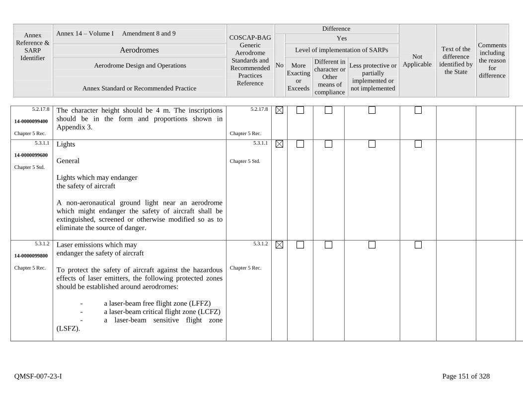
Annex
Reference &
SARP
Identifier
Annex 14 – Volume I Amendment 8 and 9 COSCAP-BAG
Generic
Aerodrome
Standards and
Recommended
Practices
Reference
Difference
Not
Applicable
Text of the
difference
identified by
the State
Comments
including
the reason
for
difference
No
Yes
Aerodromes Level of implementation of SARPs
Aerodrome Design and Operations
Annex Standard or Recommended Practice
More
Exacting
or
Exceeds
Different in
character or
Other
means of
compliance
Less protective or
partially
implemented or
not implemented
QMSF-007-23-I Page 151 of 328
5.2.17.8
14-0000099400
Chapter 5 Rec.
The character height should be 4 m. The inscriptions
should be in the form and proportions shown in
Appendix 3.
5.2.17.8
Chapter 5 Rec.
5.3.1.1
14-0000099600
Chapter 5 Std.
Lights
General
Lights which may endanger
the safety of aircraft
A non-aeronautical ground light near an aerodrome
which might endanger the safety of aircraft shall be
extinguished, screened or otherwise modified so as to
eliminate the source of danger.
5.3.1.1
Chapter 5 Std.
5.3.1.2
14-0000099800
Chapter 5 Rec.
Laser emissions which may
endanger the safety of aircraft
To protect the safety of aircraft against the hazardous
effects of laser emitters, the following protected zones
should be established around aerodromes:
- a laser-beam free flight zone (LFFZ)
- a laser-beam critical flight zone (LCFZ)
- a laser-beam sensitive flight zone
(LSFZ).
5.3.1.2
Chapter 5 Rec.
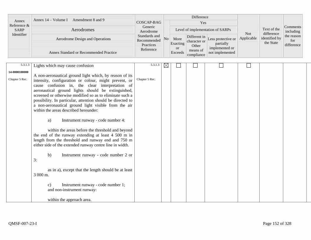
Annex
Reference &
SARP
Identifier
Annex 14 – Volume I Amendment 8 and 9 COSCAP-BAG
Generic
Aerodrome
Standards and
Recommended
Practices
Reference
Difference
Not
Applicable
Text of the
difference
identified by
the State
Comments
including
the reason
for
difference
No
Yes
Aerodromes Level of implementation of SARPs
Aerodrome Design and Operations
Annex Standard or Recommended Practice
More
Exacting
or
Exceeds
Different in
character or
Other
means of
compliance
Less protective or
partially
implemented or
not implemented
QMSF-007-23-I Page 152 of 328
5.3.1.3
14-0000100000
Chapter 5 Rec.
Lights which may cause confusion
A non-aeronautical ground light which, by reason of its
intensity, configuration or colour, might prevent, or
cause confusion in, the clear interpretation of
aeronautical ground lights should be extinguished,
screened or otherwise modified so as to eliminate such a
possibility. In particular, attention should be directed to
a non-aeronautical ground light visible from the air
within the areas described hereunder:
a) Instrument runway - code number 4:
within the areas before the threshold and beyond
the end of the runway extending at least 4 500 m in
length from the threshold and runway end and 750 m
either side of the extended runway centre line in width.
b) Instrument runway - code number 2 or
3:
as in a), except that the length should be at least
3 000 m.
c) Instrument runway - code number 1;
and non-instrument runway:
within the approach area.
5.3.1.3
Chapter 5 Rec.
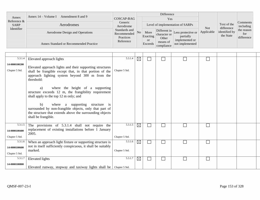
Annex
Reference &
SARP
Identifier
Annex 14 – Volume I Amendment 8 and 9 COSCAP-BAG
Generic
Aerodrome
Standards and
Recommended
Practices
Reference
Difference
Not
Applicable
Text of the
difference
identified by
the State
Comments
including
the reason
for
difference
No
Yes
Aerodromes Level of implementation of SARPs
Aerodrome Design and Operations
Annex Standard or Recommended Practice
More
Exacting
or
Exceeds
Different in
character or
Other
means of
compliance
Less protective or
partially
implemented or
not implemented
QMSF-007-23-I Page 153 of 328
5.3.1.4
14-0000100200
Chapter 5 Std.
Elevated approach lights
Elevated approach lights and their supporting structures
shall be frangible except that, in that portion of the
approach lighting system beyond 300 m from the
threshold:
a) where the height of a supporting
structure exceeds 12 m, the frangibility requirement
shall apply to the top 12 m only; and
b) where a supporting structure is
surrounded by non-frangible objects, only that part of
the structure that extends above the surrounding objects
shall be frangible.
5.3.1.4
Chapter 5 Std.
5.3.1.5
14-0000100400
Chapter 5 Std.
The provisions of 5.3.1.4 shall not require the
replacement of existing installations before 1 January
2005.
5.3.1.5
Chapter 5 Std.
5.3.1.6
14-0000100600
Chapter 5 Std.
When an approach light fixture or supporting structure is
not in itself sufficiently conspicuous, it shall be suitably
marked.
5.3.1.6
Chapter 5 Std.
5.3.1.7
14-0000100800
Elevated lights
Elevated runway, stopway and taxiway lights shall be
5.3.1.7
Chapter 5 Std.
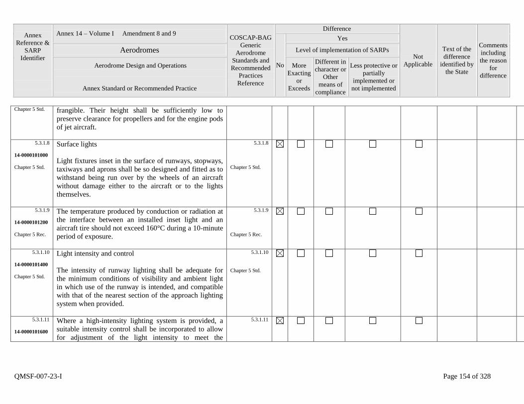
Annex
Reference &
SARP
Identifier
Annex 14 – Volume I Amendment 8 and 9 COSCAP-BAG
Generic
Aerodrome
Standards and
Recommended
Practices
Reference
Difference
Not
Applicable
Text of the
difference
identified by
the State
Comments
including
the reason
for
difference
No
Yes
Aerodromes Level of implementation of SARPs
Aerodrome Design and Operations
Annex Standard or Recommended Practice
More
Exacting
or
Exceeds
Different in
character or
Other
means of
compliance
Less protective or
partially
implemented or
not implemented
QMSF-007-23-I Page 154 of 328
Chapter 5 Std. frangible. Their height shall be sufficiently low to
preserve clearance for propellers and for the engine pods
of jet aircraft.
5.3.1.8
14-0000101000
Chapter 5 Std.
Surface lights
Light fixtures inset in the surface of runways, stopways,
taxiways and aprons shall be so designed and fitted as to
withstand being run over by the wheels of an aircraft
without damage either to the aircraft or to the lights
themselves.
5.3.1.8
Chapter 5 Std.
5.3.1.9
14-0000101200
Chapter 5 Rec.
The temperature produced by conduction or radiation at
the interface between an installed inset light and an
aircraft tire should not exceed 160°C during a 10-minute
period of exposure.
5.3.1.9
Chapter 5 Rec.
5.3.1.10
14-0000101400
Chapter 5 Std.
Light intensity and control
The intensity of runway lighting shall be adequate for
the minimum conditions of visibility and ambient light
in which use of the runway is intended, and compatible
with that of the nearest section of the approach lighting
system when provided.
5.3.1.10
Chapter 5 Std.
5.3.1.11
14-0000101600
Where a high-intensity lighting system is provided, a
suitable intensity control shall be incorporated to allow
for adjustment of the light intensity to meet the
5.3.1.11
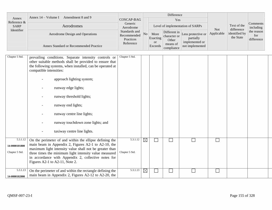
Annex
Reference &
SARP
Identifier
Annex 14 – Volume I Amendment 8 and 9 COSCAP-BAG
Generic
Aerodrome
Standards and
Recommended
Practices
Reference
Difference
Not
Applicable
Text of the
difference
identified by
the State
Comments
including
the reason
for
difference
No
Yes
Aerodromes Level of implementation of SARPs
Aerodrome Design and Operations
Annex Standard or Recommended Practice
More
Exacting
or
Exceeds
Different in
character or
Other
means of
compliance
Less protective or
partially
implemented or
not implemented
QMSF-007-23-I Page 155 of 328
Chapter 5 Std. prevailing conditions. Separate intensity controls or
other suitable methods shall be provided to ensure that
the following systems, when installed, can be operated at
compatible intensities:
- approach lighting system;
- runway edge lights;
- runway threshold lights;
- runway end lights;
- runway centre line lights;
- runway touchdown zone lights; and
- taxiway centre line lights.
Chapter 5 Std.
5.3.1.12
14-0000101800
Chapter 5 Std.
On the perimeter of and within the ellipse defining the
main beam in Appendix 2, Figures A2-1 to A2-10, the
maximum light intensity value shall not be greater than
three times the minimum light intensity value measured
in accordance with Appendix 2, collective notes for
Figures A2-1 to A2-11, Note 2.
5.3.1.12
Chapter 5 Std.
5.3.1.13
14-0000102000
On the perimeter of and within the rectangle defining the
main beam in Appendix 2, Figures A2-12 to A2-20, the
5.3.1.13
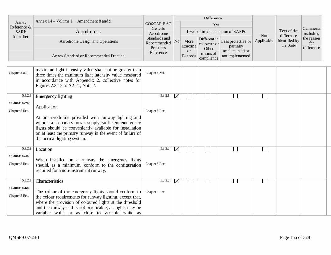
Annex
Reference &
SARP
Identifier
Annex 14 – Volume I Amendment 8 and 9 COSCAP-BAG
Generic
Aerodrome
Standards and
Recommended
Practices
Reference
Difference
Not
Applicable
Text of the
difference
identified by
the State
Comments
including
the reason
for
difference
No
Yes
Aerodromes Level of implementation of SARPs
Aerodrome Design and Operations
Annex Standard or Recommended Practice
More
Exacting
or
Exceeds
Different in
character or
Other
means of
compliance
Less protective or
partially
implemented or
not implemented
QMSF-007-23-I Page 156 of 328
Chapter 5 Std. maximum light intensity value shall not be greater than
three times the minimum light intensity value measured
in accordance with Appendix 2, collective notes for
Figures A2-12 to A2-21, Note 2.
Chapter 5 Std.
5.3.2.1
14-0000102200
Chapter 5 Rec.
Emergency lighting
Application
At an aerodrome provided with runway lighting and
without a secondary power supply, sufficient emergency
lights should be conveniently available for installation
on at least the primary runway in the event of failure of
the normal lighting system.
5.3.2.1
Chapter 5 Rec.
5.3.2.2
14-0000102400
Chapter 5 Rec.
Location
When installed on a runway the emergency lights
should, as a minimum, conform to the configuration
required for a non-instrument runway.
5.3.2.2
Chapter 5 Rec.
5.3.2.3
14-0000102600
Chapter 5 Rec.
Characteristics
The colour of the emergency lights should conform to
the colour requirements for runway lighting, except that,
where the provision of coloured lights at the threshold
and the runway end is not practicable, all lights may be
variable white or as close to variable white as
5.3.2.3
Chapter 5 Rec.
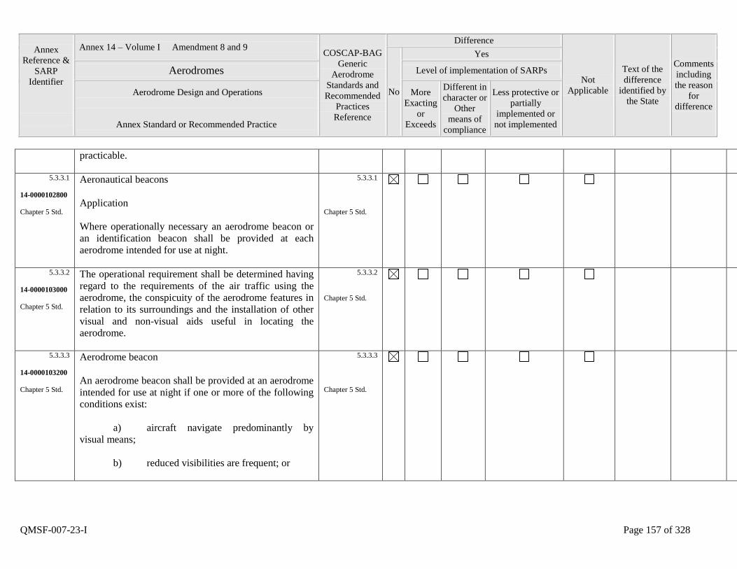
Annex
Reference &
SARP
Identifier
Annex 14 – Volume I Amendment 8 and 9 COSCAP-BAG
Generic
Aerodrome
Standards and
Recommended
Practices
Reference
Difference
Not
Applicable
Text of the
difference
identified by
the State
Comments
including
the reason
for
difference
No
Yes
Aerodromes Level of implementation of SARPs
Aerodrome Design and Operations
Annex Standard or Recommended Practice
More
Exacting
or
Exceeds
Different in
character or
Other
means of
compliance
Less protective or
partially
implemented or
not implemented
QMSF-007-23-I Page 157 of 328
practicable.
5.3.3.1
14-0000102800
Chapter 5 Std.
Aeronautical beacons
Application
Where operationally necessary an aerodrome beacon or
an identification beacon shall be provided at each
aerodrome intended for use at night.
5.3.3.1
Chapter 5 Std.
5.3.3.2
14-0000103000
Chapter 5 Std.
The operational requirement shall be determined having
regard to the requirements of the air traffic using the
aerodrome, the conspicuity of the aerodrome features in
relation to its surroundings and the installation of other
visual and non-visual aids useful in locating the
aerodrome.
5.3.3.2
Chapter 5 Std.
5.3.3.3
14-0000103200
Chapter 5 Std.
Aerodrome beacon
An aerodrome beacon shall be provided at an aerodrome
intended for use at night if one or more of the following
conditions exist:
a) aircraft navigate predominantly by
visual means;
b) reduced visibilities are frequent; or
5.3.3.3
Chapter 5 Std.
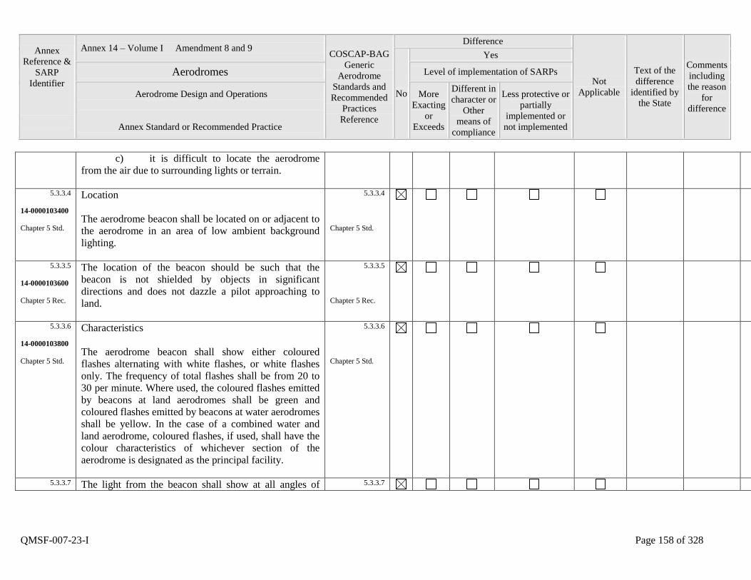
Annex
Reference &
SARP
Identifier
Annex 14 – Volume I Amendment 8 and 9 COSCAP-BAG
Generic
Aerodrome
Standards and
Recommended
Practices
Reference
Difference
Not
Applicable
Text of the
difference
identified by
the State
Comments
including
the reason
for
difference
No
Yes
Aerodromes Level of implementation of SARPs
Aerodrome Design and Operations
Annex Standard or Recommended Practice
More
Exacting
or
Exceeds
Different in
character or
Other
means of
compliance
Less protective or
partially
implemented or
not implemented
QMSF-007-23-I Page 158 of 328
c) it is difficult to locate the aerodrome
from the air due to surrounding lights or terrain.
5.3.3.4
14-0000103400
Chapter 5 Std.
Location
The aerodrome beacon shall be located on or adjacent to
the aerodrome in an area of low ambient background
lighting.
5.3.3.4
Chapter 5 Std.
5.3.3.5
14-0000103600
Chapter 5 Rec.
The location of the beacon should be such that the
beacon is not shielded by objects in significant
directions and does not dazzle a pilot approaching to
land.
5.3.3.5
Chapter 5 Rec.
5.3.3.6
14-0000103800
Chapter 5 Std.
Characteristics
The aerodrome beacon shall show either coloured
flashes alternating with white flashes, or white flashes
only. The frequency of total flashes shall be from 20 to
30 per minute. Where used, the coloured flashes emitted
by beacons at land aerodromes shall be green and
coloured flashes emitted by beacons at water aerodromes
shall be yellow. In the case of a combined water and
land aerodrome, coloured flashes, if used, shall have the
colour characteristics of whichever section of the
aerodrome is designated as the principal facility.
5.3.3.6
Chapter 5 Std.
5.3.3.7 The light from the beacon shall show at all angles of 5.3.3.7
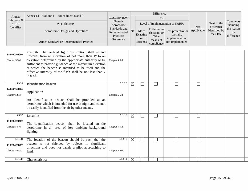
Annex
Reference &
SARP
Identifier
Annex 14 – Volume I Amendment 8 and 9 COSCAP-BAG
Generic
Aerodrome
Standards and
Recommended
Practices
Reference
Difference
Not
Applicable
Text of the
difference
identified by
the State
Comments
including
the reason
for
difference
No
Yes
Aerodromes Level of implementation of SARPs
Aerodrome Design and Operations
Annex Standard or Recommended Practice
More
Exacting
or
Exceeds
Different in
character or
Other
means of
compliance
Less protective or
partially
implemented or
not implemented
QMSF-007-23-I Page 159 of 328
14-0000104000
Chapter 5 Std.
azimuth. The vertical light distribution shall extend
upwards from an elevation of not more than 1° to an
elevation determined by the appropriate authority to be
sufficient to provide guidance at the maximum elevation
at which the beacon is intended to be used and the
effective intensity of the flash shall be not less than 2
000 cd.
Chapter 5 Std.
5.3.3.8
14-0000104200
Chapter 5 Std.
Identification beacon
Application
An identification beacon shall be provided at an
aerodrome which is intended for use at night and cannot
be easily identified from the air by other means.
5.3.3.8
Chapter 5 Std.
5.3.3.9
14-0000104400
Chapter 5 Std.
Location
The identification beacon shall be located on the
aerodrome in an area of low ambient background
lighting.
5.3.3.9
Chapter 5 Std.
5.3.3.10
14-0000104600
Chapter 5 Rec.
The location of the beacon should be such that the
beacon is not shielded by objects in significant
directions and does not dazzle a pilot approaching to
land.
5.3.3.10
Chapter 5 Rec.
5.3.3.11 Characteristics 5.3.3.11

Annex
Reference &
SARP
Identifier
Annex 14 – Volume I Amendment 8 and 9 COSCAP-BAG
Generic
Aerodrome
Standards and
Recommended
Practices
Reference
Difference
Not
Applicable
Text of the
difference
identified by
the State
Comments
including
the reason
for
difference
No
Yes
Aerodromes Level of implementation of SARPs
Aerodrome Design and Operations
Annex Standard or Recommended Practice
More
Exacting
or
Exceeds
Different in
character or
Other
means of
compliance
Less protective or
partially
implemented or
not implemented
QMSF-007-23-I Page 160 of 328
14-0000104800
Chapter 5 Std.
An identification beacon at a land aerodrome shall show
at all angles of azimuth. The vertical light distribution
shall extend upwards from an elevation of not more than
1° to an elevation determined by the appropriate
authority to be sufficient to provide guidance at the
maximum elevation at which the beacon is intended to
be used and the effective intensity of the flash shall be
not less than 2 000 cd.
Chapter 5 Std.
5.3.3.12
14-0000105000
Chapter 5 Std.
An identification beacon shall show flashing-green at a
land aerodrome and flashing-yellow at a water
aerodrome.
5.3.3.12
Chapter 5 Std.
5.3.3.13
14-0000105200
Chapter 5 Std.
The identification characters shall be transmitted in the
International Morse Code.
5.3.3.13
Chapter 5 Std.
5.3.3.14
14-0000105400
Chapter 5 Rec.
The speed of transmission should be between six and
eight words per minute, the corresponding range of
duration of the Morse dots being from 0.15 to 0.2
seconds per dot.
5.3.3.14
Chapter 5 Rec.
5.3.4.1
14-0000105600
Chapter 5 Rec.
Application
Application
A. - Non-instrument runway
5.3.4.1
Chapter 5 Rec.
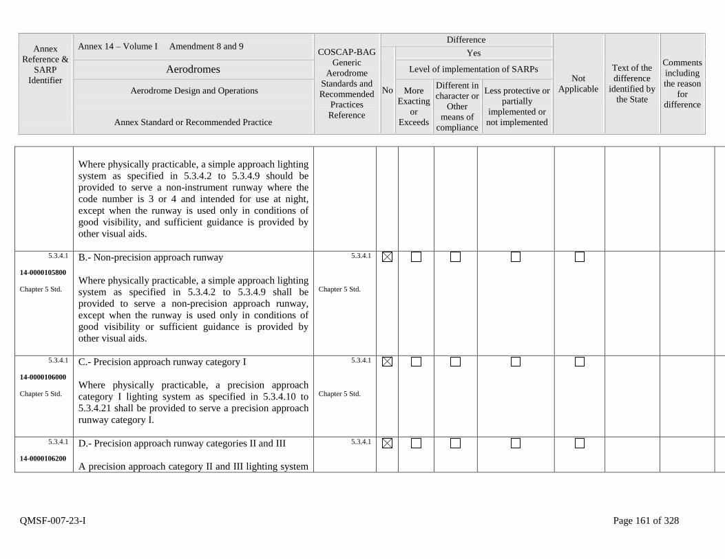
Annex
Reference &
SARP
Identifier
Annex 14 – Volume I Amendment 8 and 9 COSCAP-BAG
Generic
Aerodrome
Standards and
Recommended
Practices
Reference
Difference
Not
Applicable
Text of the
difference
identified by
the State
Comments
including
the reason
for
difference
No
Yes
Aerodromes Level of implementation of SARPs
Aerodrome Design and Operations
Annex Standard or Recommended Practice
More
Exacting
or
Exceeds
Different in
character or
Other
means of
compliance
Less protective or
partially
implemented or
not implemented
QMSF-007-23-I Page 161 of 328
Where physically practicable, a simple approach lighting
system as specified in 5.3.4.2 to 5.3.4.9 should be
provided to serve a non-instrument runway where the
code number is 3 or 4 and intended for use at night,
except when the runway is used only in conditions of
good visibility, and sufficient guidance is provided by
other visual aids.
5.3.4.1
14-0000105800
Chapter 5 Std.
B.- Non-precision approach runway
Where physically practicable, a simple approach lighting
system as specified in 5.3.4.2 to 5.3.4.9 shall be
provided to serve a non-precision approach runway,
except when the runway is used only in conditions of
good visibility or sufficient guidance is provided by
other visual aids.
5.3.4.1
Chapter 5 Std.
5.3.4.1
14-0000106000
Chapter 5 Std.
C.- Precision approach runway category I
Where physically practicable, a precision approach
category I lighting system as specified in 5.3.4.10 to
5.3.4.21 shall be provided to serve a precision approach
runway category I.
5.3.4.1
Chapter 5 Std.
5.3.4.1
14-0000106200
D.- Precision approach runway categories II and III
A precision approach category II and III lighting system
5.3.4.1
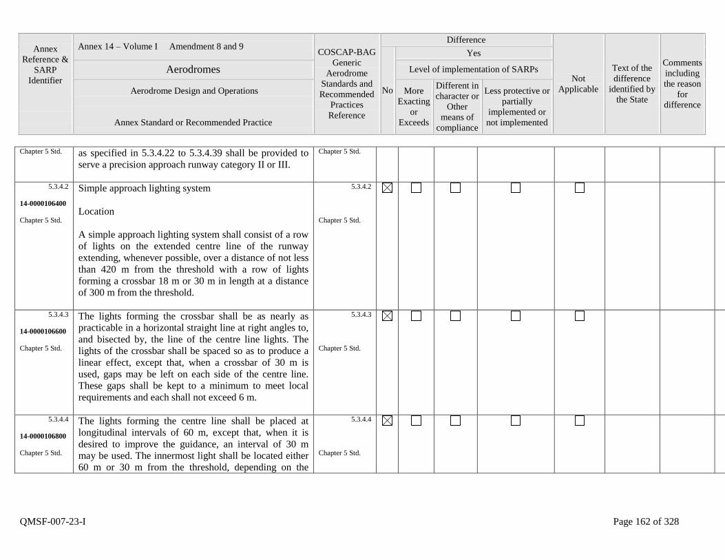
Annex
Reference &
SARP
Identifier
Annex 14 – Volume I Amendment 8 and 9 COSCAP-BAG
Generic
Aerodrome
Standards and
Recommended
Practices
Reference
Difference
Not
Applicable
Text of the
difference
identified by
the State
Comments
including
the reason
for
difference
No
Yes
Aerodromes Level of implementation of SARPs
Aerodrome Design and Operations
Annex Standard or Recommended Practice
More
Exacting
or
Exceeds
Different in
character or
Other
means of
compliance
Less protective or
partially
implemented or
not implemented
QMSF-007-23-I Page 162 of 328
Chapter 5 Std. as specified in 5.3.4.22 to 5.3.4.39 shall be provided to
serve a precision approach runway category II or III.
Chapter 5 Std.
5.3.4.2
14-0000106400
Chapter 5 Std.
Simple approach lighting system
Location
A simple approach lighting system shall consist of a row
of lights on the extended centre line of the runway
extending, whenever possible, over a distance of not less
than 420 m from the threshold with a row of lights
forming a crossbar 18 m or 30 m in length at a distance
of 300 m from the threshold.
5.3.4.2
Chapter 5 Std.
5.3.4.3
14-0000106600
Chapter 5 Std.
The lights forming the crossbar shall be as nearly as
practicable in a horizontal straight line at right angles to,
and bisected by, the line of the centre line lights. The
lights of the crossbar shall be spaced so as to produce a
linear effect, except that, when a crossbar of 30 m is
used, gaps may be left on each side of the centre line.
These gaps shall be kept to a minimum to meet local
requirements and each shall not exceed 6 m.
5.3.4.3
Chapter 5 Std.
5.3.4.4
14-0000106800
Chapter 5 Std.
The lights forming the centre line shall be placed at
longitudinal intervals of 60 m, except that, when it is
desired to improve the guidance, an interval of 30 m
may be used. The innermost light shall be located either
60 m or 30 m from the threshold, depending on the
5.3.4.4
Chapter 5 Std.
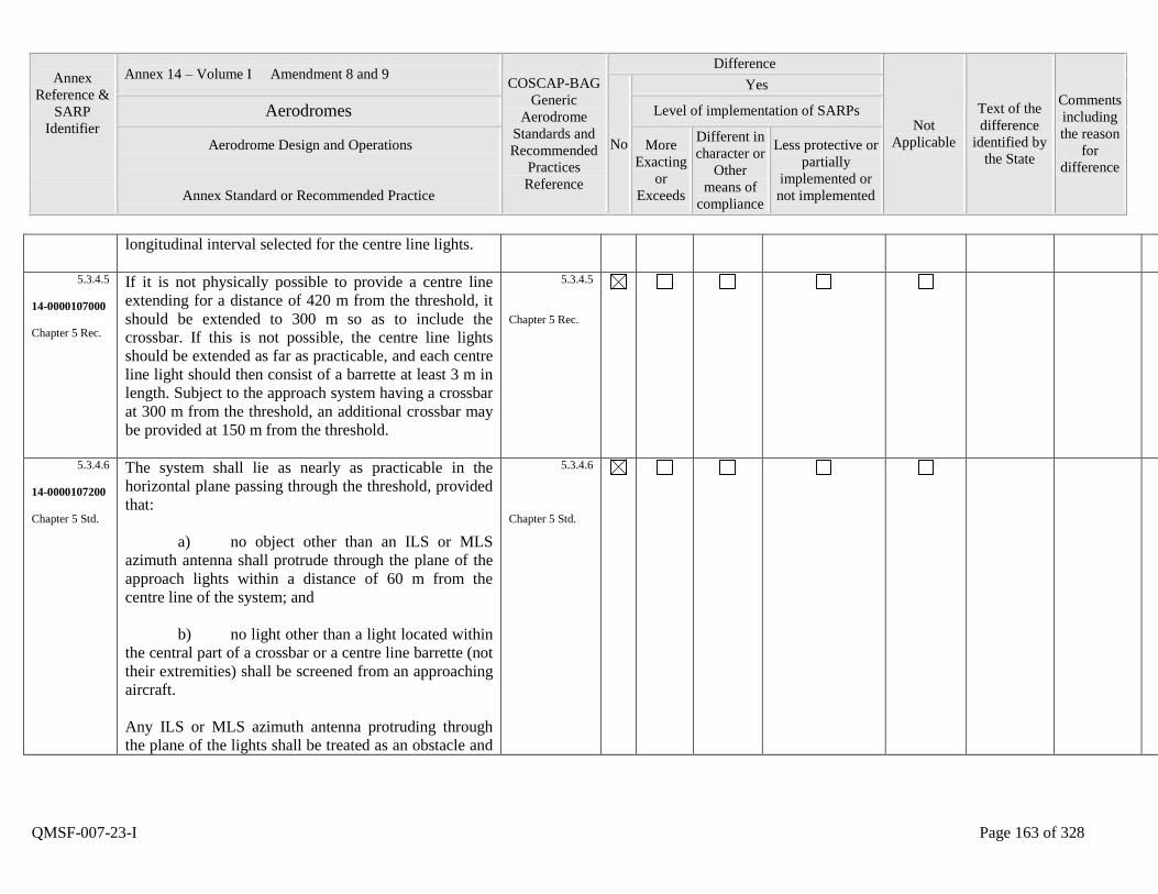
Annex
Reference &
SARP
Identifier
Annex 14 – Volume I Amendment 8 and 9 COSCAP-BAG
Generic
Aerodrome
Standards and
Recommended
Practices
Reference
Difference
Not
Applicable
Text of the
difference
identified by
the State
Comments
including
the reason
for
difference
No
Yes
Aerodromes Level of implementation of SARPs
Aerodrome Design and Operations
Annex Standard or Recommended Practice
More
Exacting
or
Exceeds
Different in
character or
Other
means of
compliance
Less protective or
partially
implemented or
not implemented
QMSF-007-23-I Page 163 of 328
longitudinal interval selected for the centre line lights.
5.3.4.5
14-0000107000
Chapter 5 Rec.
If it is not physically possible to provide a centre line
extending for a distance of 420 m from the threshold, it
should be extended to 300 m so as to include the
crossbar. If this is not possible, the centre line lights
should be extended as far as practicable, and each centre
line light should then consist of a barrette at least 3 m in
length. Subject to the approach system having a crossbar
at 300 m from the threshold, an additional crossbar may
be provided at 150 m from the threshold.
5.3.4.5
Chapter 5 Rec.
5.3.4.6
14-0000107200
Chapter 5 Std.
The system shall lie as nearly as practicable in the
horizontal plane passing through the threshold, provided
that:
a) no object other than an ILS or MLS
azimuth antenna shall protrude through the plane of the
approach lights within a distance of 60 m from the
centre line of the system; and
b) no light other than a light located within
the central part of a crossbar or a centre line barrette (not
their extremities) shall be screened from an approaching
aircraft.
Any ILS or MLS azimuth antenna protruding through
the plane of the lights shall be treated as an obstacle and
5.3.4.6
Chapter 5 Std.
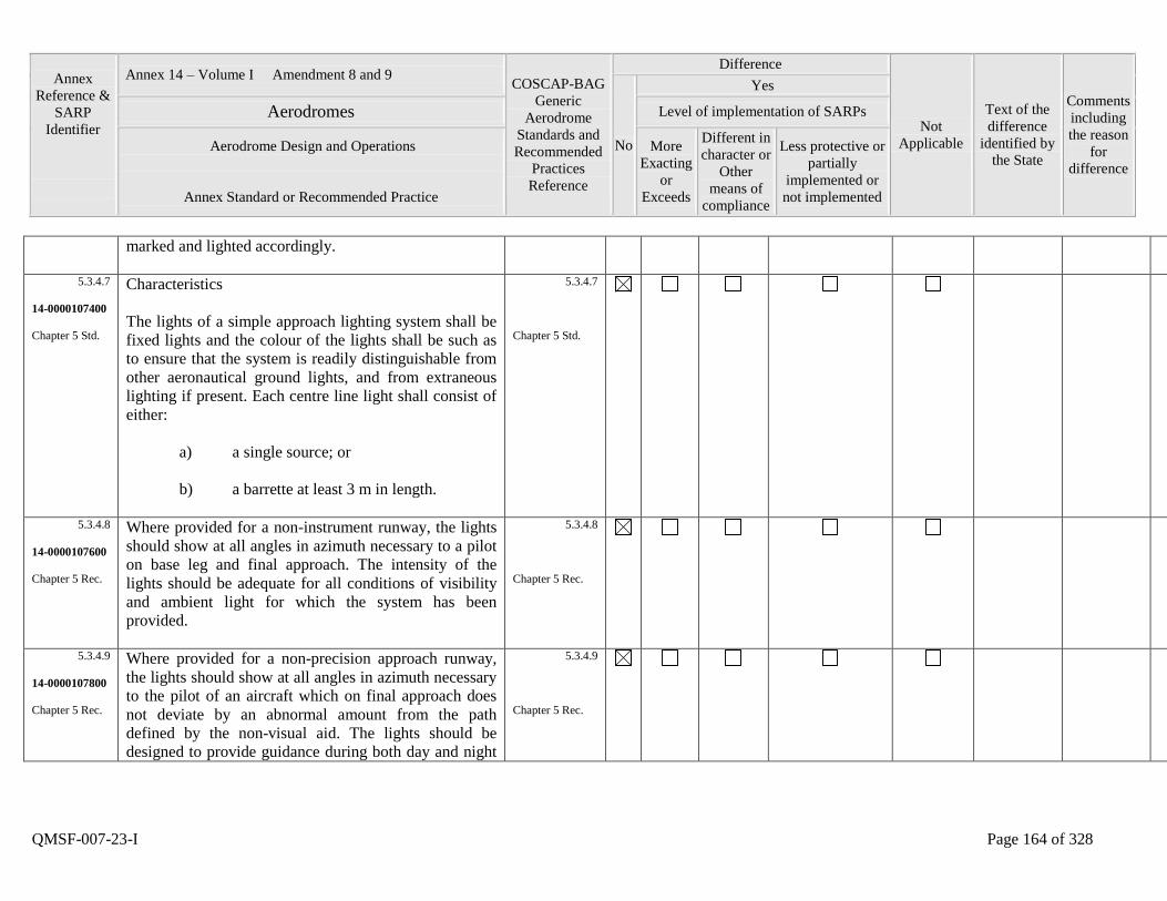
Annex
Reference &
SARP
Identifier
Annex 14 – Volume I Amendment 8 and 9 COSCAP-BAG
Generic
Aerodrome
Standards and
Recommended
Practices
Reference
Difference
Not
Applicable
Text of the
difference
identified by
the State
Comments
including
the reason
for
difference
No
Yes
Aerodromes Level of implementation of SARPs
Aerodrome Design and Operations
Annex Standard or Recommended Practice
More
Exacting
or
Exceeds
Different in
character or
Other
means of
compliance
Less protective or
partially
implemented or
not implemented
QMSF-007-23-I Page 164 of 328
marked and lighted accordingly.
5.3.4.7
14-0000107400
Chapter 5 Std.
Characteristics
The lights of a simple approach lighting system shall be
fixed lights and the colour of the lights shall be such as
to ensure that the system is readily distinguishable from
other aeronautical ground lights, and from extraneous
lighting if present. Each centre line light shall consist of
either:
a) a single source; or
b) a barrette at least 3 m in length.
5.3.4.7
Chapter 5 Std.
5.3.4.8
14-0000107600
Chapter 5 Rec.
Where provided for a non-instrument runway, the lights
should show at all angles in azimuth necessary to a pilot
on base leg and final approach. The intensity of the
lights should be adequate for all conditions of visibility
and ambient light for which the system has been
provided.
5.3.4.8
Chapter 5 Rec.
5.3.4.9
14-0000107800
Chapter 5 Rec.
Where provided for a non-precision approach runway,
the lights should show at all angles in azimuth necessary
to the pilot of an aircraft which on final approach does
not deviate by an abnormal amount from the path
defined by the non-visual aid. The lights should be
designed to provide guidance during both day and night
5.3.4.9
Chapter 5 Rec.

Annex
Reference &
SARP
Identifier
Annex 14 – Volume I Amendment 8 and 9 COSCAP-BAG
Generic
Aerodrome
Standards and
Recommended
Practices
Reference
Difference
Not
Applicable
Text of the
difference
identified by
the State
Comments
including
the reason
for
difference
No
Yes
Aerodromes Level of implementation of SARPs
Aerodrome Design and Operations
Annex Standard or Recommended Practice
More
Exacting
or
Exceeds
Different in
character or
Other
means of
compliance
Less protective or
partially
implemented or
not implemented
QMSF-007-23-I Page 165 of 328
in the most adverse conditions of visibility and ambient
light for which it is intended that the system should
remain usable.
5.3.4.10
14-0000108000
Chapter 5 Std.
Precision approach category I
lighting system
Location
A precision approach category I lighting system shall
consist of a row of lights on the extended centre line of
the runway extending, wherever possible, over a
distance of 900 m from the runway threshold with a row
of lights forming a crossbar 30 m in length at a distance
of 300 m from the runway threshold.
5.3.4.10
Chapter 5 Std.
5.3.4.11
14-0000108200
Chapter 5 Std.
The lights forming the crossbar shall be as nearly as
practicable in a horizontal straight line at right angles to,
and bisected by, the line of the centre line lights. The
lights of the crossbar shall be spaced so as to produce a
linear effect, except that gaps may be left on each side of
the centre line. These gaps shall be kept to a minimum to
meet local requirements and each shall not exceed 6 m.
5.3.4.11
Chapter 5 Std.
5.3.4.12
14-0000108400
Chapter 5 Std.
The lights forming the centre line shall be placed at
longitudinal intervals of 30 m with the innermost light
located 30 m from the threshold.
5.3.4.12
Chapter 5 Std.
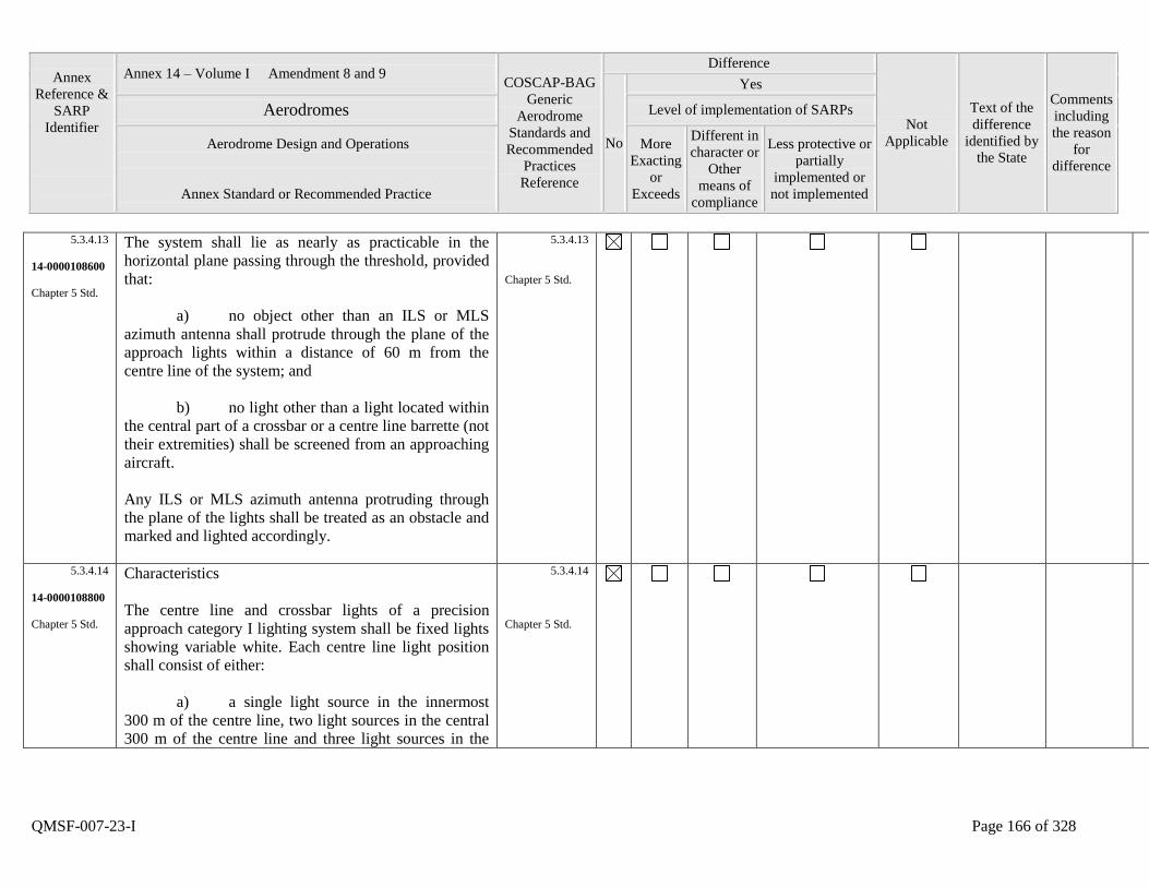
Annex
Reference &
SARP
Identifier
Annex 14 – Volume I Amendment 8 and 9 COSCAP-BAG
Generic
Aerodrome
Standards and
Recommended
Practices
Reference
Difference
Not
Applicable
Text of the
difference
identified by
the State
Comments
including
the reason
for
difference
No
Yes
Aerodromes Level of implementation of SARPs
Aerodrome Design and Operations
Annex Standard or Recommended Practice
More
Exacting
or
Exceeds
Different in
character or
Other
means of
compliance
Less protective or
partially
implemented or
not implemented
QMSF-007-23-I Page 166 of 328
5.3.4.13
14-0000108600
Chapter 5 Std.
The system shall lie as nearly as practicable in the
horizontal plane passing through the threshold, provided
that:
a) no object other than an ILS or MLS
azimuth antenna shall protrude through the plane of the
approach lights within a distance of 60 m from the
centre line of the system; and
b) no light other than a light located within
the central part of a crossbar or a centre line barrette (not
their extremities) shall be screened from an approaching
aircraft.
Any ILS or MLS azimuth antenna protruding through
the plane of the lights shall be treated as an obstacle and
marked and lighted accordingly.
5.3.4.13
Chapter 5 Std.
5.3.4.14
14-0000108800
Chapter 5 Std.
Characteristics
The centre line and crossbar lights of a precision
approach category I lighting system shall be fixed lights
showing variable white. Each centre line light position
shall consist of either:
a) a single light source in the innermost
300 m of the centre line, two light sources in the central
300 m of the centre line and three light sources in the
5.3.4.14
Chapter 5 Std.
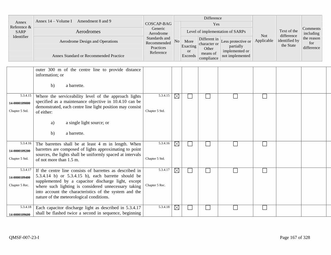
Annex
Reference &
SARP
Identifier
Annex 14 – Volume I Amendment 8 and 9 COSCAP-BAG
Generic
Aerodrome
Standards and
Recommended
Practices
Reference
Difference
Not
Applicable
Text of the
difference
identified by
the State
Comments
including
the reason
for
difference
No
Yes
Aerodromes Level of implementation of SARPs
Aerodrome Design and Operations
Annex Standard or Recommended Practice
More
Exacting
or
Exceeds
Different in
character or
Other
means of
compliance
Less protective or
partially
implemented or
not implemented
QMSF-007-23-I Page 167 of 328
outer 300 m of the centre line to provide distance
information; or
b) a barrette.
5.3.4.15
14-0000109000
Chapter 5 Std.
Where the serviceability level of the approach lights
specified as a maintenance objective in 10.4.10 can be
demonstrated, each centre line light position may consist
of either:
a) a single light source; or
b) a barrette.
5.3.4.15
Chapter 5 Std.
5.3.4.16
14-0000109200
Chapter 5 Std.
The barrettes shall be at least 4 m in length. When
barrettes are composed of lights approximating to point
sources, the lights shall be uniformly spaced at intervals
of not more than 1.5 m.
5.3.4.16
Chapter 5 Std.
5.3.4.17
14-0000109400
Chapter 5 Rec.
If the centre line consists of barrettes as described in
5.3.4.14 b) or 5.3.4.15 b), each barrette should be
supplemented by a capacitor discharge light, except
where such lighting is considered unnecessary taking
into account the characteristics of the system and the
nature of the meteorological conditions.
5.3.4.17
Chapter 5 Rec.
5.3.4.18
14-0000109600
Each capacitor discharge light as described in 5.3.4.17
shall be flashed twice a second in sequence, beginning
5.3.4.18
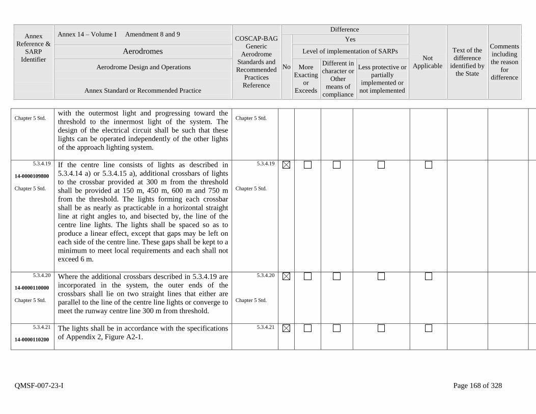
Annex
Reference &
SARP
Identifier
Annex 14 – Volume I Amendment 8 and 9 COSCAP-BAG
Generic
Aerodrome
Standards and
Recommended
Practices
Reference
Difference
Not
Applicable
Text of the
difference
identified by
the State
Comments
including
the reason
for
difference
No
Yes
Aerodromes Level of implementation of SARPs
Aerodrome Design and Operations
Annex Standard or Recommended Practice
More
Exacting
or
Exceeds
Different in
character or
Other
means of
compliance
Less protective or
partially
implemented or
not implemented
QMSF-007-23-I Page 168 of 328
Chapter 5 Std. with the outermost light and progressing toward the
threshold to the innermost light of the system. The
design of the electrical circuit shall be such that these
lights can be operated independently of the other lights
of the approach lighting system.
Chapter 5 Std.
5.3.4.19
14-0000109800
Chapter 5 Std.
If the centre line consists of lights as described in
5.3.4.14 a) or 5.3.4.15 a), additional crossbars of lights
to the crossbar provided at 300 m from the threshold
shall be provided at 150 m, 450 m, 600 m and 750 m
from the threshold. The lights forming each crossbar
shall be as nearly as practicable in a horizontal straight
line at right angles to, and bisected by, the line of the
centre line lights. The lights shall be spaced so as to
produce a linear effect, except that gaps may be left on
each side of the centre line. These gaps shall be kept to a
minimum to meet local requirements and each shall not
exceed 6 m.
5.3.4.19
Chapter 5 Std.
5.3.4.20
14-0000110000
Chapter 5 Std.
Where the additional crossbars described in 5.3.4.19 are
incorporated in the system, the outer ends of the
crossbars shall lie on two straight lines that either are
parallel to the line of the centre line lights or converge to
meet the runway centre line 300 m from threshold.
5.3.4.20
Chapter 5 Std.
5.3.4.21
14-0000110200
The lights shall be in accordance with the specifications
of Appendix 2, Figure A2-1.
5.3.4.21
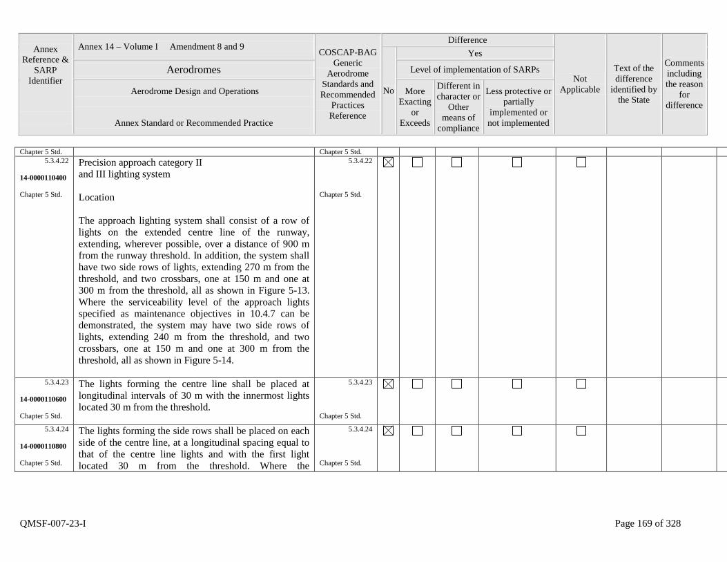
Annex
Reference &
SARP
Identifier
Annex 14 – Volume I Amendment 8 and 9 COSCAP-BAG
Generic
Aerodrome
Standards and
Recommended
Practices
Reference
Difference
Not
Applicable
Text of the
difference
identified by
the State
Comments
including
the reason
for
difference
No
Yes
Aerodromes Level of implementation of SARPs
Aerodrome Design and Operations
Annex Standard or Recommended Practice
More
Exacting
or
Exceeds
Different in
character or
Other
means of
compliance
Less protective or
partially
implemented or
not implemented
QMSF-007-23-I Page 169 of 328
Chapter 5 Std. Chapter 5 Std.
5.3.4.22
14-0000110400
Chapter 5 Std.
Precision approach category II
and III lighting system
Location
The approach lighting system shall consist of a row of
lights on the extended centre line of the runway,
extending, wherever possible, over a distance of 900 m
from the runway threshold. In addition, the system shall
have two side rows of lights, extending 270 m from the
threshold, and two crossbars, one at 150 m and one at
300 m from the threshold, all as shown in Figure 5-13.
Where the serviceability level of the approach lights
specified as maintenance objectives in 10.4.7 can be
demonstrated, the system may have two side rows of
lights, extending 240 m from the threshold, and two
crossbars, one at 150 m and one at 300 m from the
threshold, all as shown in Figure 5-14.
5.3.4.22
Chapter 5 Std.
5.3.4.23
14-0000110600
Chapter 5 Std.
The lights forming the centre line shall be placed at
longitudinal intervals of 30 m with the innermost lights
located 30 m from the threshold.
5.3.4.23
Chapter 5 Std.
5.3.4.24
14-0000110800
Chapter 5 Std.
The lights forming the side rows shall be placed on each
side of the centre line, at a longitudinal spacing equal to
that of the centre line lights and with the first light
located 30 m from the threshold. Where the
5.3.4.24
Chapter 5 Std.
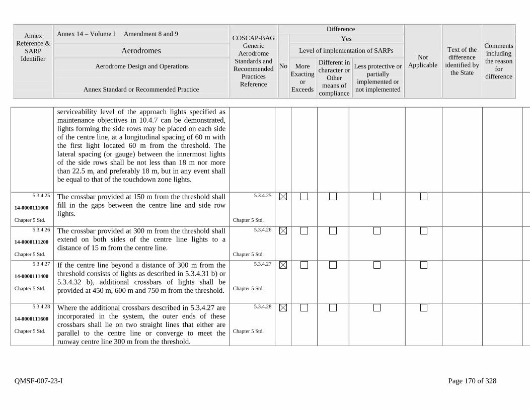
Annex
Reference &
SARP
Identifier
Annex 14 – Volume I Amendment 8 and 9 COSCAP-BAG
Generic
Aerodrome
Standards and
Recommended
Practices
Reference
Difference
Not
Applicable
Text of the
difference
identified by
the State
Comments
including
the reason
for
difference
No
Yes
Aerodromes Level of implementation of SARPs
Aerodrome Design and Operations
Annex Standard or Recommended Practice
More
Exacting
or
Exceeds
Different in
character or
Other
means of
compliance
Less protective or
partially
implemented or
not implemented
QMSF-007-23-I Page 170 of 328
serviceability level of the approach lights specified as
maintenance objectives in 10.4.7 can be demonstrated,
lights forming the side rows may be placed on each side
of the centre line, at a longitudinal spacing of 60 m with
the first light located 60 m from the threshold. The
lateral spacing (or gauge) between the innermost lights
of the side rows shall be not less than 18 m nor more
than 22.5 m, and preferably 18 m, but in any event shall
be equal to that of the touchdown zone lights.
5.3.4.25
14-0000111000
Chapter 5 Std.
The crossbar provided at 150 m from the threshold shall
fill in the gaps between the centre line and side row
lights.
5.3.4.25
Chapter 5 Std.
5.3.4.26
14-0000111200
Chapter 5 Std.
The crossbar provided at 300 m from the threshold shall
extend on both sides of the centre line lights to a
distance of 15 m from the centre line.
5.3.4.26
Chapter 5 Std.
5.3.4.27
14-0000111400
Chapter 5 Std.
If the centre line beyond a distance of 300 m from the
threshold consists of lights as described in 5.3.4.31 b) or
5.3.4.32 b), additional crossbars of lights shall be
provided at 450 m, 600 m and 750 m from the threshold.
5.3.4.27
Chapter 5 Std.
5.3.4.28
14-0000111600
Chapter 5 Std.
Where the additional crossbars described in 5.3.4.27 are
incorporated in the system, the outer ends of these
crossbars shall lie on two straight lines that either are
parallel to the centre line or converge to meet the
runway centre line 300 m from the threshold.
5.3.4.28
Chapter 5 Std.
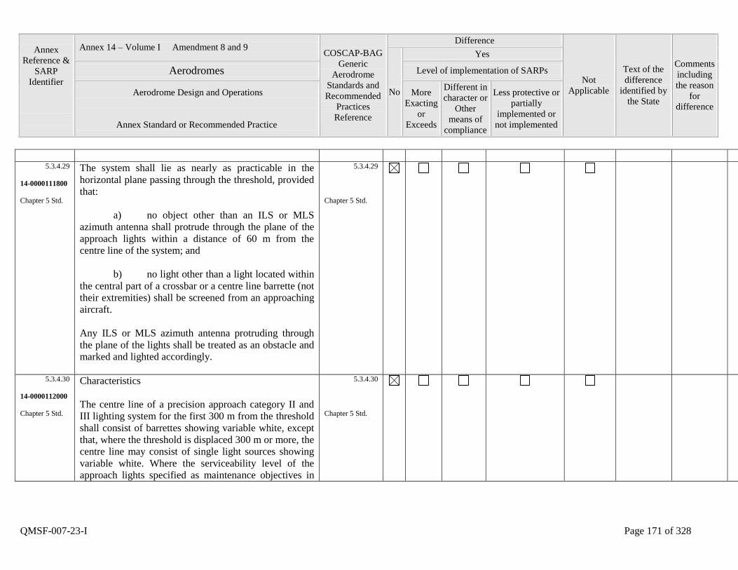
Annex
Reference &
SARP
Identifier
Annex 14 – Volume I Amendment 8 and 9 COSCAP-BAG
Generic
Aerodrome
Standards and
Recommended
Practices
Reference
Difference
Not
Applicable
Text of the
difference
identified by
the State
Comments
including
the reason
for
difference
No
Yes
Aerodromes Level of implementation of SARPs
Aerodrome Design and Operations
Annex Standard or Recommended Practice
More
Exacting
or
Exceeds
Different in
character or
Other
means of
compliance
Less protective or
partially
implemented or
not implemented
QMSF-007-23-I Page 171 of 328
5.3.4.29
14-0000111800
Chapter 5 Std.
The system shall lie as nearly as practicable in the
horizontal plane passing through the threshold, provided
that:
a) no object other than an ILS or MLS
azimuth antenna shall protrude through the plane of the
approach lights within a distance of 60 m from the
centre line of the system; and
b) no light other than a light located within
the central part of a crossbar or a centre line barrette (not
their extremities) shall be screened from an approaching
aircraft.
Any ILS or MLS azimuth antenna protruding through
the plane of the lights shall be treated as an obstacle and
marked and lighted accordingly.
5.3.4.29
Chapter 5 Std.
5.3.4.30
14-0000112000
Chapter 5 Std.
Characteristics
The centre line of a precision approach category II and
III lighting system for the first 300 m from the threshold
shall consist of barrettes showing variable white, except
that, where the threshold is displaced 300 m or more, the
centre line may consist of single light sources showing
variable white. Where the serviceability level of the
approach lights specified as maintenance objectives in
5.3.4.30
Chapter 5 Std.
Annex
Reference &
SARP
Identifier
Annex 14 – Volume I Amendment 8 and 9 COSCAP-BAG
Generic
Aerodrome
Standards and
Recommended
Practices
Reference
Difference
Not
Applicable
Text of the
difference
identified by
the State
Comments
including
the reason
for
difference
No
Yes
Aerodromes Level of implementation of SARPs
Aerodrome Design and Operations
Annex Standard or Recommended Practice
More
Exacting
or
Exceeds
Different in
character or
Other
means of
compliance
Less protective or
partially
implemented or
not implemented
QMSF-007-23-I Page 172 of 328
10.4.7 can be demonstrated, the centre line of a precision
approach category II and III lighting system for the first
300 m from the threshold may consist of either:
a) barrettes, where the centre line beyond
300 m from the threshold consists of barrettes as
described in 5.3.4.32 a); or
b) alternate single light sources and
barrettes, where the centre line beyond 300 m from the
threshold consists of single light sources as described in
5.3.4.32 b), with the innermost single light source
located 30 m and the innermost barrette located 60 m
from the threshold; or
c) single light sources where the threshold
is displaced 300 m or more;
all of which shall show variable white.
5.3.4.31
14-0000112200
Chapter 5 Std.
Beyond 300 m from the threshold each centre line light
position shall consist of either:
a) a barrette as used on the inner 300 m; or
b) two light sources in the central 300 m of
the centre line and three light sources in the outer 300 m
of the centre line;
5.3.4.31
Chapter 5 Std.
Annex
Reference &
SARP
Identifier
Annex 14 – Volume I Amendment 8 and 9 COSCAP-BAG
Generic
Aerodrome
Standards and
Recommended
Practices
Reference
Difference
Not
Applicable
Text of the
difference
identified by
the State
Comments
including
the reason
for
difference
No
Yes
Aerodromes Level of implementation of SARPs
Aerodrome Design and Operations
Annex Standard or Recommended Practice
More
Exacting
or
Exceeds
Different in
character or
Other
means of
compliance
Less protective or
partially
implemented or
not implemented
QMSF-007-23-I Page 173 of 328
all of which shall show variable white.
5.3.4.32
14-0000112400
Chapter 5 Std.
Where the serviceability level of the approach lights
specified as maintenance objectives in 10.4.7 can be
demonstrated, beyond 300 m from the threshold each
centre line light position may consist of either:
a) a barrette; or
b) a single light source;
all of which shall show variable white.
5.3.4.32
Chapter 5 Std.
5.3.4.33
14-0000112600
Chapter 5 Std.
The barrettes shall be at least 4 m in length. When
barrettes are composed of lights approximating to point
sources, the lights shall be uniformly spaced at intervals
of not more than 1.5 m.
5.3.4.33
Chapter 5 Std.
5.3.4.34
14-0000112800
Chapter 5 Rec.
If the centre line beyond 300 m from the threshold
consists of barrettes as described in 5.3.4.31 a) or
5.3.4.32 a), each barrette beyond 300 m should be
supplemented by a capacitor discharge light, except
where such lighting is considered unnecessary taking
into account the characteristics of the system and the
nature of the meteorological conditions.
5.3.4.34
Chapter 5 Rec.
5.3.4.35 Each capacitor discharge light shall be flashed twice a 5.3.4.35
Annex
Reference &
SARP
Identifier
Annex 14 – Volume I Amendment 8 and 9 COSCAP-BAG
Generic
Aerodrome
Standards and
Recommended
Practices
Reference
Difference
Not
Applicable
Text of the
difference
identified by
the State
Comments
including
the reason
for
difference
No
Yes
Aerodromes Level of implementation of SARPs
Aerodrome Design and Operations
Annex Standard or Recommended Practice
More
Exacting
or
Exceeds
Different in
character or
Other
means of
compliance
Less protective or
partially
implemented or
not implemented
QMSF-007-23-I Page 174 of 328
14-0000113000
Chapter 5 Std.
second in sequence, beginning with the outermost light
and progressing toward the threshold to the innermost
light of the system. The design of the electrical circuit
shall be such that these lights can be operated
independently of the other lights of the approach lighting
system.
Chapter 5 Std.
5.3.4.36
14-0000113200
Chapter 5 Std.
The side row shall consist of barrettes showing red. The
length of a side row barrette and the spacing of its lights
shall be equal to those of the touchdown zone light
barrettes.
5.3.4.36
Chapter 5 Std.
5.3.4.37
14-0000113400
Chapter 5 Std.
The lights forming the crossbars shall be fixed lights
showing variable white. The lights shall be uniformly
spaced at intervals of not more than 2.7 m.
5.3.4.37
Chapter 5 Std.
5.3.4.38
14-0000113600
Chapter 5 Std.
The intensity of the red lights shall be compatible with
the intensity of the white lights.
5.3.4.38
Chapter 5 Std.
5.3.4.39
14-0000113800
Chapter 5 Std.
The lights shall be in accordance with the specifications
of Appendix 2, Figures A2-1 and A2-2.
5.3.4.39
Chapter 5 Std.
5.3.5.1
14-0000114000
Chapter 5 Std.
Visual approach slope indicator systems
Application
A visual approach slope indicator system shall be
5.3.5.1
Chapter 5 Std.
Annex
Reference &
SARP
Identifier
Annex 14 – Volume I Amendment 8 and 9 COSCAP-BAG
Generic
Aerodrome
Standards and
Recommended
Practices
Reference
Difference
Not
Applicable
Text of the
difference
identified by
the State
Comments
including
the reason
for
difference
No
Yes
Aerodromes Level of implementation of SARPs
Aerodrome Design and Operations
Annex Standard or Recommended Practice
More
Exacting
or
Exceeds
Different in
character or
Other
means of
compliance
Less protective or
partially
implemented or
not implemented
QMSF-007-23-I Page 175 of 328
provided to serve the approach to a runway whether or
not the runway is served by other visual approach aids or
by non-visual aids, where one or more of the following
conditions exist:
a) the runway is used by turbojet or other
aeroplanes with similar approach guidance requirements;
b) the pilot of any type of aeroplane may
have difficulty in judging the approach due to:
1) inadequate visual guidance such
as is experienced during an approach over water or
featureless terrain by day or in the absence of sufficient
extraneous lights in the approach area by night, or
2) misleading information such as
is produced by deceptive surrounding terrain or runway
slopes;
c) the presence of objects in the approach
area may involve serious hazard if an aeroplane
descends below the normal approach path, particularly if
there are no non-visual or other visual aids to give
warning of such objects;
d) physical conditions at either end of the
runway present a serious hazard in the event of an

Annex
Reference &
SARP
Identifier
Annex 14 – Volume I Amendment 8 and 9 COSCAP-BAG
Generic
Aerodrome
Standards and
Recommended
Practices
Reference
Difference
Not
Applicable
Text of the
difference
identified by
the State
Comments
including
the reason
for
difference
No
Yes
Aerodromes Level of implementation of SARPs
Aerodrome Design and Operations
Annex Standard or Recommended Practice
More
Exacting
or
Exceeds
Different in
character or
Other
means of
compliance
Less protective or
partially
implemented or
not implemented
QMSF-007-23-I Page 176 of 328
aeroplane undershooting or overrunning the runway; and
e) terrain or prevalent meteorological
conditions are such that the aeroplane may be subjected
to unusual turbulence during approach.
5.3.5.2
14-0000114200
Chapter 5 Std.
The standard visual approach slope indicator systems
shall consist of the following:
a) T-VASIS and AT-VASIS conforming to
the specifications contained in 5.3.5.6 to 5.3.5.22
inclusive;
b) PAPI and APAPI systems conforming
to the specifications contained in 5.3.5.23 to 5.3.5.40
inclusive;
as shown in Figure 5-15.
5.3.5.2
Chapter 5 Std.
5.3.5.3
14-0000114400
Chapter 5 Std.
PAPI, T-VASIS or AT-VASIS shall be provided where
the code number is 3 or 4 when one or more of the
conditions specified in 5.3.5.1 exist.
5.3.5.3
Chapter 5 Std.
5.3.5.4
14-0000114600
Chapter 5 Std.
PAPI or APAPI shall be provided where the code
number is 1 or 2 when one or more of the conditions
specified in 5.3.5.1 exist.
5.3.5.4
Chapter 5 Std.
5.3.5.5 Where a runway threshold is temporarily displaced from 5.3.5.5
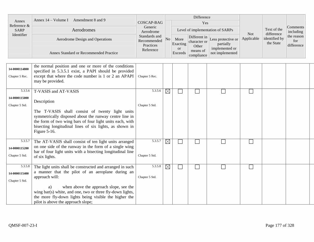
Annex
Reference &
SARP
Identifier
Annex 14 – Volume I Amendment 8 and 9 COSCAP-BAG
Generic
Aerodrome
Standards and
Recommended
Practices
Reference
Difference
Not
Applicable
Text of the
difference
identified by
the State
Comments
including
the reason
for
difference
No
Yes
Aerodromes Level of implementation of SARPs
Aerodrome Design and Operations
Annex Standard or Recommended Practice
More
Exacting
or
Exceeds
Different in
character or
Other
means of
compliance
Less protective or
partially
implemented or
not implemented
QMSF-007-23-I Page 177 of 328
14-0000114800
Chapter 5 Rec.
the normal position and one or more of the conditions
specified in 5.3.5.1 exist, a PAPI should be provided
except that where the code number is 1 or 2 an APAPI
may be provided.
Chapter 5 Rec.
5.3.5.6
14-0000115000
Chapter 5 Std.
T-VASIS and AT-VASIS
Description
The T-VASIS shall consist of twenty light units
symmetrically disposed about the runway centre line in
the form of two wing bars of four light units each, with
bisecting longitudinal lines of six lights, as shown in
Figure 5-16.
5.3.5.6
Chapter 5 Std.
5.3.5.7
14-0000115200
Chapter 5 Std.
The AT-VASIS shall consist of ten light units arranged
on one side of the runway in the form of a single wing
bar of four light units with a bisecting longitudinal line
of six lights.
5.3.5.7
Chapter 5 Std.
5.3.5.8
14-0000115400
Chapter 5 Std.
The light units shall be constructed and arranged in such
a manner that the pilot of an aeroplane during an
approach will:
a) when above the approach slope, see the
wing bar(s) white, and one, two or three fly-down lights,
the more fly-down lights being visible the higher the
pilot is above the approach slope;
5.3.5.8
Chapter 5 Std.
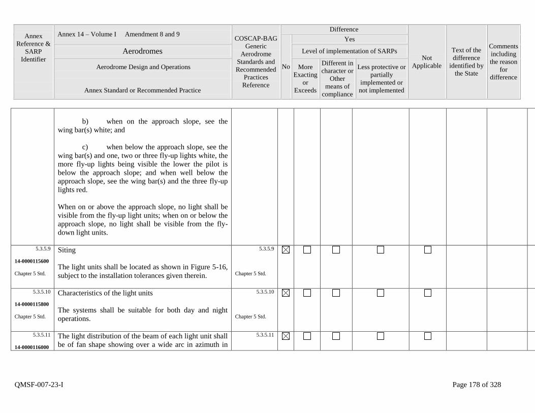
Annex
Reference &
SARP
Identifier
Annex 14 – Volume I Amendment 8 and 9 COSCAP-BAG
Generic
Aerodrome
Standards and
Recommended
Practices
Reference
Difference
Not
Applicable
Text of the
difference
identified by
the State
Comments
including
the reason
for
difference
No
Yes
Aerodromes Level of implementation of SARPs
Aerodrome Design and Operations
Annex Standard or Recommended Practice
More
Exacting
or
Exceeds
Different in
character or
Other
means of
compliance
Less protective or
partially
implemented or
not implemented
QMSF-007-23-I Page 178 of 328
b) when on the approach slope, see the
wing bar(s) white; and
c) when below the approach slope, see the
wing bar(s) and one, two or three fly-up lights white, the
more fly-up lights being visible the lower the pilot is
below the approach slope; and when well below the
approach slope, see the wing bar(s) and the three fly-up
lights red.
When on or above the approach slope, no light shall be
visible from the fly-up light units; when on or below the
approach slope, no light shall be visible from the fly-
down light units.
5.3.5.9
14-0000115600
Chapter 5 Std.
Siting
The light units shall be located as shown in Figure 5-16,
subject to the installation tolerances given therein.
5.3.5.9
Chapter 5 Std.
5.3.5.10
14-0000115800
Chapter 5 Std.
Characteristics of the light units
The systems shall be suitable for both day and night
operations.
5.3.5.10
Chapter 5 Std.
5.3.5.11
14-0000116000
The light distribution of the beam of each light unit shall
be of fan shape showing over a wide arc in azimuth in
5.3.5.11
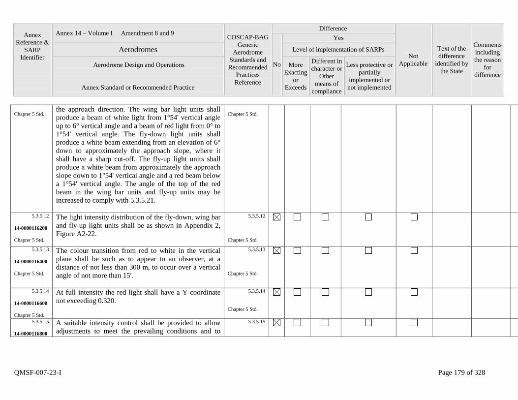
Annex
Reference &
SARP
Identifier
Annex 14 – Volume I Amendment 8 and 9 COSCAP-BAG
Generic
Aerodrome
Standards and
Recommended
Practices
Reference
Difference
Not
Applicable
Text of the
difference
identified by
the State
Comments
including
the reason
for
difference
No
Yes
Aerodromes Level of implementation of SARPs
Aerodrome Design and Operations
Annex Standard or Recommended Practice
More
Exacting
or
Exceeds
Different in
character or
Other
means of
compliance
Less protective or
partially
implemented or
not implemented
QMSF-007-23-I Page 179 of 328
Chapter 5 Std. the approach direction. The wing bar light units shall
produce a beam of white light from 1°54' vertical angle
up to 6° vertical angle and a beam of red light from 0° to
1°54' vertical angle. The fly-down light units shall
produce a white beam extending from an elevation of 6°
down to approximately the approach slope, where it
shall have a sharp cut-off. The fly-up light units shall
produce a white beam from approximately the approach
slope down to 1°54' vertical angle and a red beam below
a 1°54' vertical angle. The angle of the top of the red
beam in the wing bar units and fly-up units may be
increased to comply with 5.3.5.21.
Chapter 5 Std.
5.3.5.12
14-0000116200
Chapter 5 Std.
The light intensity distribution of the fly-down, wing bar
and fly-up light units shall be as shown in Appendix 2,
Figure A2-22.
5.3.5.12
Chapter 5 Std.
5.3.5.13
14-0000116400
Chapter 5 Std.
The colour transition from red to white in the vertical
plane shall be such as to appear to an observer, at a
distance of not less than 300 m, to occur over a vertical
angle of not more than 15'.
5.3.5.13
Chapter 5 Std.
5.3.5.14
14-0000116600
Chapter 5 Std.
At full intensity the red light shall have a Y coordinate
not exceeding 0.320.
5.3.5.14
Chapter 5 Std.
5.3.5.15
14-0000116800
A suitable intensity control shall be provided to allow
adjustments to meet the prevailing conditions and to
5.3.5.15
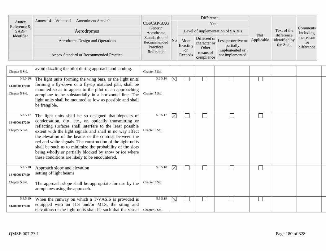
Annex
Reference &
SARP
Identifier
Annex 14 – Volume I Amendment 8 and 9 COSCAP-BAG
Generic
Aerodrome
Standards and
Recommended
Practices
Reference
Difference
Not
Applicable
Text of the
difference
identified by
the State
Comments
including
the reason
for
difference
No
Yes
Aerodromes Level of implementation of SARPs
Aerodrome Design and Operations
Annex Standard or Recommended Practice
More
Exacting
or
Exceeds
Different in
character or
Other
means of
compliance
Less protective or
partially
implemented or
not implemented
QMSF-007-23-I Page 180 of 328
Chapter 5 Std. avoid dazzling the pilot during approach and landing.
Chapter 5 Std.
5.3.5.16
14-0000117000
Chapter 5 Std.
The light units forming the wing bars, or the light units
forming a fly-down or a fly-up matched pair, shall be
mounted so as to appear to the pilot of an approaching
aeroplane to be substantially in a horizontal line. The
light units shall be mounted as low as possible and shall
be frangible.
5.3.5.16
Chapter 5 Std.
5.3.5.17
14-0000117200
Chapter 5 Std.
The light units shall be so designed that deposits of
condensation, dirt, etc., on optically transmitting or
reflecting surfaces shall interfere to the least possible
extent with the light signals and shall in no way affect
the elevation of the beams or the contrast between the
red and white signals. The construction of the light units
shall be such as to minimize the probability of the slots
being wholly or partially blocked by snow or ice where
these conditions are likely to be encountered.
5.3.5.17
Chapter 5 Std.
5.3.5.18
14-0000117400
Chapter 5 Std.
Approach slope and elevation
setting of light beams
The approach slope shall be appropriate for use by the
aeroplanes using the approach.
5.3.5.18
Chapter 5 Std.
5.3.5.19
14-0000117600
When the runway on which a T-VASIS is provided is
equipped with an ILS and/or MLS, the siting and
elevations of the light units shall be such that the visual
5.3.5.19
Chapter 5 Std.
Annex
Reference &
SARP
Identifier
Annex 14 – Volume I Amendment 8 and 9 COSCAP-BAG
Generic
Aerodrome
Standards and
Recommended
Practices
Reference
Difference
Not
Applicable
Text of the
difference
identified by
the State
Comments
including
the reason
for
difference
No
Yes
Aerodromes Level of implementation of SARPs
Aerodrome Design and Operations
Annex Standard or Recommended Practice
More
Exacting
or
Exceeds
Different in
character or
Other
means of
compliance
Less protective or
partially
implemented or
not implemented
QMSF-007-23-I Page 181 of 328
Chapter 5 Std. approach slope conforms as closely as possible with the
glide path of the ILS and/ or the minimum glide path of
the MLS, as appropriate.
5.3.5.20
14-0000117800
Chapter 5 Std.
The elevation of the beams of the wing bar light units on
both sides of the runway shall be the same. The
elevation of the top of the beam of the fly-up light unit
nearest to each wing bar, and that of the bottom of the
beam of the fly-down light unit nearest to each wing bar,
shall be equal and shall correspond to the approach
slope. The cut-off angle of the top of the beams of
successive fly-up light units shall decrease by 5' of arc in
angle of elevation at each successive unit away from the
wing bar. The cut-in angle of the bottom of the beam of
the fly-down light units shall increase by 7' of arc at each
successive unit away from the wing bar (see Figure 5-
17).
5.3.5.20
Chapter 5 Std.
5.3.5.21
14-0000118000
Chapter 5 Std.
The elevation setting of the top of the red light beams of
the wing bar and fly-up light units shall be such that,
during an approach, the pilot of an aeroplane to whom
the wing bar and three fly-up light units are visible
would clear all objects in the approach area by a safe
margin if any such light did not appear red.
5.3.5.21
Chapter 5 Std.
5.3.5.22
14-0000118200
The azimuth spread of the light beam shall be suitably
restricted where an object located outside the obstacle
protection surface of the system, but within the lateral
5.3.5.22
Chapter 5 Std.

Annex
Reference &
SARP
Identifier
Annex 14 – Volume I Amendment 8 and 9 COSCAP-BAG
Generic
Aerodrome
Standards and
Recommended
Practices
Reference
Difference
Not
Applicable
Text of the
difference
identified by
the State
Comments
including
the reason
for
difference
No
Yes
Aerodromes Level of implementation of SARPs
Aerodrome Design and Operations
Annex Standard or Recommended Practice
More
Exacting
or
Exceeds
Different in
character or
Other
means of
compliance
Less protective or
partially
implemented or
not implemented
QMSF-007-23-I Page 182 of 328
Chapter 5 Std. limits of its light beam, is found to extend above the
plane of the obstacle protection surface and an
aeronautical study indicates that the object could
adversely affect the safety of operations. The extent of
the restriction shall be such that the object remains
outside the confines of the light beam.
5.3.5.23
14-0000118400
Chapter 5 Std.
PAPI and APAPI
Description
The PAPI system shall consist of a wing bar of 4 sharp
transition multi-lamp (or paired single lamp) units
equally spaced. The system shall be located on the left
side of the runway unless it is physically impracticable
to do so.
5.3.5.23
Chapter 5 Std.
5.3.5.24
14-0000118600
Chapter 5 Std.
The APAPI system shall consist of a wing bar of 2 sharp
transition multi-lamp (or paired single lamp) units. The
system shall be located on the left side of the runway
unless it is physically impracticable to do so.
5.3.5.24
Chapter 5 Std.
5.3.5.25
14-0000118800
Chapter 5 Std.
The wing bar of a PAPI shall be constructed and
arranged in such a manner that a pilot making an
approach will:
a) when on or close to the approach slope,
see the two units nearest the runway as red and the two
5.3.5.25
Chapter 5 Std.
Annex
Reference &
SARP
Identifier
Annex 14 – Volume I Amendment 8 and 9 COSCAP-BAG
Generic
Aerodrome
Standards and
Recommended
Practices
Reference
Difference
Not
Applicable
Text of the
difference
identified by
the State
Comments
including
the reason
for
difference
No
Yes
Aerodromes Level of implementation of SARPs
Aerodrome Design and Operations
Annex Standard or Recommended Practice
More
Exacting
or
Exceeds
Different in
character or
Other
means of
compliance
Less protective or
partially
implemented or
not implemented
QMSF-007-23-I Page 183 of 328
units farthest from the runway as white;
b) when above the approach slope, see the
one unit nearest the runway as red and the three units
farthest from the runway as white; and when further
above the approach slope, see all the units as white; and
c) when below the approach slope, see the
three units nearest the runway as red and the unit farthest
from the runway as white; and when further below the
approach slope, see all the units as red.
5.3.5.26
14-0000119000
Chapter 5 Std.
The wing bar of an APAPI shall be constructed and
arranged in such a manner that a pilot making an
approach will:
a) when on or close to the approach slope,
see the unit nearer the runway as red and the unit farther
from the runway as white;
b) when above the approach slope, see
both the units as white; and
c) when below the approach slope, see
both the units as red.
5.3.5.26
Chapter 5 Std.
5.3.5.27
14-0000119200
Siting
5.3.5.27
Annex
Reference &
SARP
Identifier
Annex 14 – Volume I Amendment 8 and 9 COSCAP-BAG
Generic
Aerodrome
Standards and
Recommended
Practices
Reference
Difference
Not
Applicable
Text of the
difference
identified by
the State
Comments
including
the reason
for
difference
No
Yes
Aerodromes Level of implementation of SARPs
Aerodrome Design and Operations
Annex Standard or Recommended Practice
More
Exacting
or
Exceeds
Different in
character or
Other
means of
compliance
Less protective or
partially
implemented or
not implemented
QMSF-007-23-I Page 184 of 328
Chapter 5 Std. The light units shall be located as in the basic
configuration illustrated in Figure 5-18, subject to the
installation tolerances given therein. The units forming a
wing bar shall be mounted so as to appear to the pilot of
an approaching aeroplane to be substantially in a
horizontal line. The light units shall be mounted as low
as possible and shall be frangible.
Chapter 5 Std.
5.3.5.28
14-0000119400
Chapter 5 Std.
Characteristics of the light units
The system shall be suitable for both day and night
operations.
5.3.5.28
Chapter 5 Std.
5.3.5.29
14-0000119600
Chapter 5 Std.
The colour transition from red to white in the vertical
plane shall be such as to appear to an observer, at a
distance of not less than 300 m, to occur within a
vertical angle of not more than 3'.
5.3.5.29
Chapter 5 Std.
5.3.5.30
14-0000119800
Chapter 5 Std.
At full intensity the red light shall have a Y coordinate
not exceeding 0.320.
5.3.5.30
Chapter 5 Std.
5.3.5.31
14-0000120000
Chapter 5 Std.
The light intensity distribution of the light units shall be
as shown in Appendix 2, Figure A2-23.
5.3.5.31
Chapter 5 Std.
5.3.5.32
14-0000120200
Suitable intensity control shall be provided so as to
allow adjustment to meet the prevailing conditions and
to avoid dazzling the pilot during approach and landing.
5.3.5.32
Annex
Reference &
SARP
Identifier
Annex 14 – Volume I Amendment 8 and 9 COSCAP-BAG
Generic
Aerodrome
Standards and
Recommended
Practices
Reference
Difference
Not
Applicable
Text of the
difference
identified by
the State
Comments
including
the reason
for
difference
No
Yes
Aerodromes Level of implementation of SARPs
Aerodrome Design and Operations
Annex Standard or Recommended Practice
More
Exacting
or
Exceeds
Different in
character or
Other
means of
compliance
Less protective or
partially
implemented or
not implemented
QMSF-007-23-I Page 185 of 328
Chapter 5 Std. Chapter 5 Std.
5.3.5.33
14-0000120400
Chapter 5 Std.
Each light unit shall be capable of adjustment in
elevation so that the lower limit of the white part of the
beam may be fixed at any desired angle of elevation
between 1°30' and at least 4°30' above the horizontal.
5.3.5.33
Chapter 5 Std.
5.3.5.34
14-0000120600
Chapter 5 Std.
The light units shall be so designed that deposits of
condensation, snow, ice, dirt, etc., on optically
transmitting or reflecting surfaces shall interfere to the
least possible extent with the light signals and shall not
affect the contrast between the red and white signals and
the elevation of the transition sector.
5.3.5.34
Chapter 5 Std.
5.3.5.35
14-0000120800
Chapter 5 Std.
Approach slope and elevation
setting of light units
The approach slope as defined in Figure 5-19 shall be
appropriate for use by the aeroplanes using the approach.
5.3.5.35
Chapter 5 Std.
5.3.5.36
14-0000121000
Chapter 5 Std.
When the runway is equipped with an ILS and/or MLS,
the siting and the angle of elevation of the light units
shall be such that the visual approach slope conforms as
closely as possible with the glide path of the ILS and/or
the minimum glide path of the MLS, as appropriate.
5.3.5.36
Chapter 5 Std.
5.3.5.37
14-0000121200
The angle of elevation settings of the light units in a
PAPI wing bar shall be such that, during an approach,
the pilot of an aeroplane observing a signal of one white
5.3.5.37
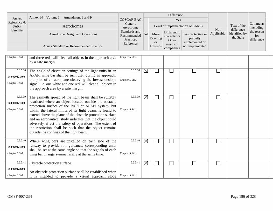
Annex
Reference &
SARP
Identifier
Annex 14 – Volume I Amendment 8 and 9 COSCAP-BAG
Generic
Aerodrome
Standards and
Recommended
Practices
Reference
Difference
Not
Applicable
Text of the
difference
identified by
the State
Comments
including
the reason
for
difference
No
Yes
Aerodromes Level of implementation of SARPs
Aerodrome Design and Operations
Annex Standard or Recommended Practice
More
Exacting
or
Exceeds
Different in
character or
Other
means of
compliance
Less protective or
partially
implemented or
not implemented
QMSF-007-23-I Page 186 of 328
Chapter 5 Std. and three reds will clear all objects in the approach area
by a safe margin.
Chapter 5 Std.
5.3.5.38
14-0000121400
Chapter 5 Std.
The angle of elevation settings of the light units in an
APAPI wing bar shall be such that, during an approach,
the pilot of an aeroplane observing the lowest onslope
signal, i.e. one white and one red, will clear all objects in
the approach area by a safe margin.
5.3.5.38
Chapter 5 Std.
5.3.5.39
14-0000121600
Chapter 5 Std.
The azimuth spread of the light beam shall be suitably
restricted where an object located outside the obstacle
protection surface of the PAPI or APAPI system, but
within the lateral limits of its light beam, is found to
extend above the plane of the obstacle protection surface
and an aeronautical study indicates that the object could
adversely affect the safety of operations. The extent of
the restriction shall be such that the object remains
outside the confines of the light beam.
5.3.5.39
Chapter 5 Std.
5.3.5.40
14-0000121800
Chapter 5 Std.
Where wing bars are installed on each side of the
runway to provide roll guidance, corresponding units
shall be set at the same angle so that the signals of each
wing bar change symmetrically at the same time.
5.3.5.40
Chapter 5 Std.
5.3.5.41
14-0000122000
Chapter 5 Std.
Obstacle protection surface
An obstacle protection surface shall be established when
it is intended to provide a visual approach slope
5.3.5.41
Chapter 5 Std.
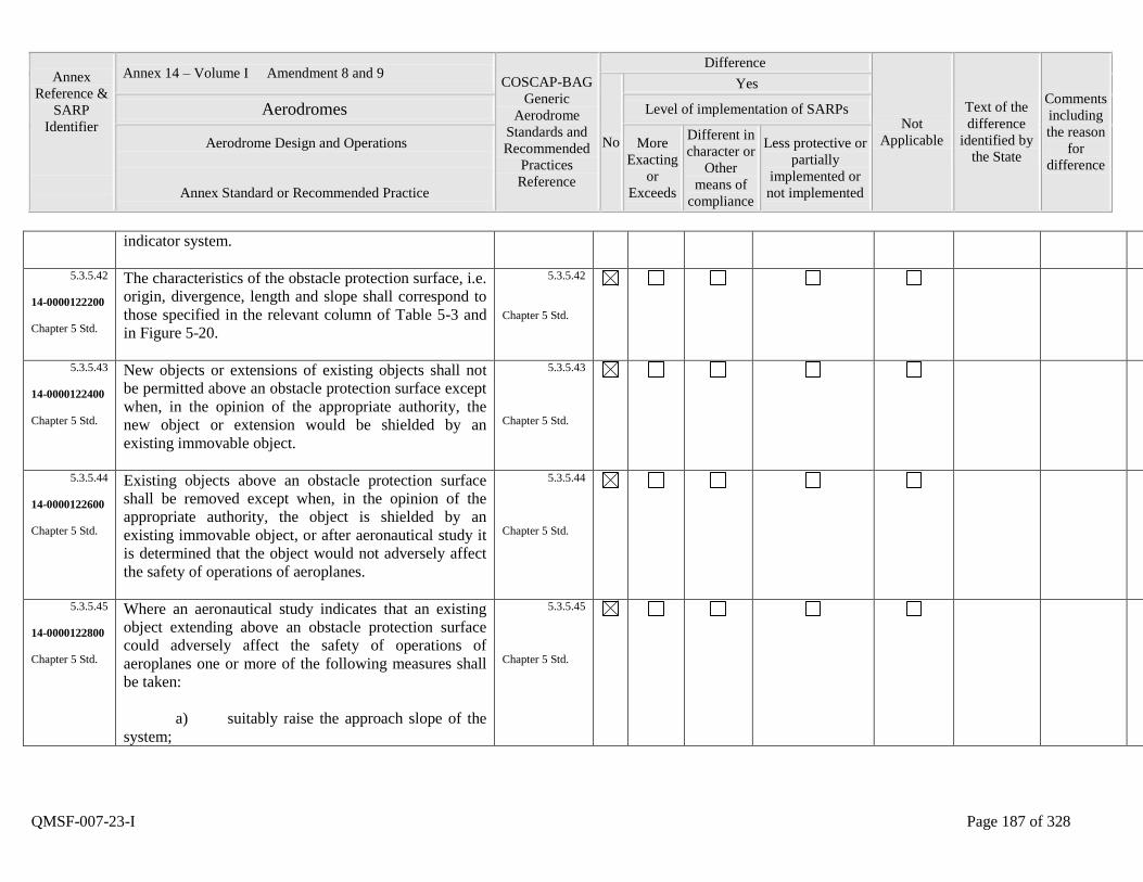
Annex
Reference &
SARP
Identifier
Annex 14 – Volume I Amendment 8 and 9 COSCAP-BAG
Generic
Aerodrome
Standards and
Recommended
Practices
Reference
Difference
Not
Applicable
Text of the
difference
identified by
the State
Comments
including
the reason
for
difference
No
Yes
Aerodromes Level of implementation of SARPs
Aerodrome Design and Operations
Annex Standard or Recommended Practice
More
Exacting
or
Exceeds
Different in
character or
Other
means of
compliance
Less protective or
partially
implemented or
not implemented
QMSF-007-23-I Page 187 of 328
indicator system.
5.3.5.42
14-0000122200
Chapter 5 Std.
The characteristics of the obstacle protection surface, i.e.
origin, divergence, length and slope shall correspond to
those specified in the relevant column of Table 5-3 and
in Figure 5-20.
5.3.5.42
Chapter 5 Std.
5.3.5.43
14-0000122400
Chapter 5 Std.
New objects or extensions of existing objects shall not
be permitted above an obstacle protection surface except
when, in the opinion of the appropriate authority, the
new object or extension would be shielded by an
existing immovable object.
5.3.5.43
Chapter 5 Std.
5.3.5.44
14-0000122600
Chapter 5 Std.
Existing objects above an obstacle protection surface
shall be removed except when, in the opinion of the
appropriate authority, the object is shielded by an
existing immovable object, or after aeronautical study it
is determined that the object would not adversely affect
the safety of operations of aeroplanes.
5.3.5.44
Chapter 5 Std.
5.3.5.45
14-0000122800
Chapter 5 Std.
Where an aeronautical study indicates that an existing
object extending above an obstacle protection surface
could adversely affect the safety of operations of
aeroplanes one or more of the following measures shall
be taken:
a) suitably raise the approach slope of the
system;
5.3.5.45
Chapter 5 Std.
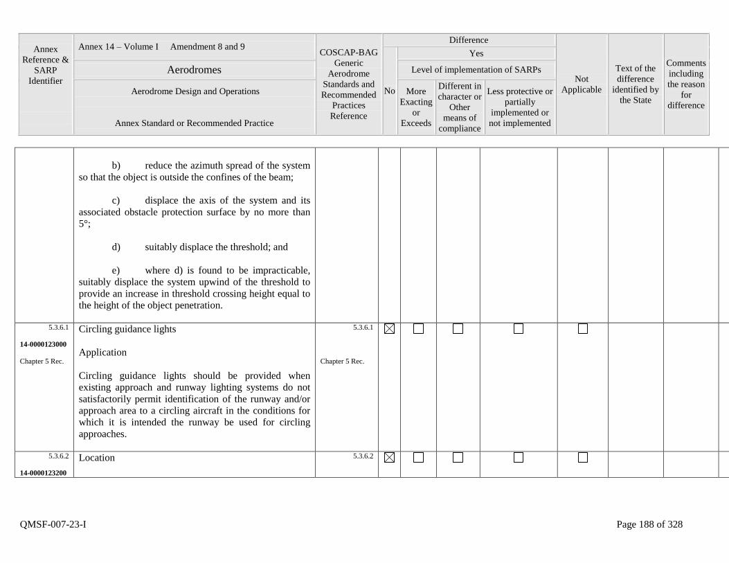
Annex
Reference &
SARP
Identifier
Annex 14 – Volume I Amendment 8 and 9 COSCAP-BAG
Generic
Aerodrome
Standards and
Recommended
Practices
Reference
Difference
Not
Applicable
Text of the
difference
identified by
the State
Comments
including
the reason
for
difference
No
Yes
Aerodromes Level of implementation of SARPs
Aerodrome Design and Operations
Annex Standard or Recommended Practice
More
Exacting
or
Exceeds
Different in
character or
Other
means of
compliance
Less protective or
partially
implemented or
not implemented
QMSF-007-23-I Page 188 of 328
b) reduce the azimuth spread of the system
so that the object is outside the confines of the beam;
c) displace the axis of the system and its
associated obstacle protection surface by no more than
5°;
d) suitably displace the threshold; and
e) where d) is found to be impracticable,
suitably displace the system upwind of the threshold to
provide an increase in threshold crossing height equal to
the height of the object penetration.
5.3.6.1
14-0000123000
Chapter 5 Rec.
Circling guidance lights
Application
Circling guidance lights should be provided when
existing approach and runway lighting systems do not
satisfactorily permit identification of the runway and/or
approach area to a circling aircraft in the conditions for
which it is intended the runway be used for circling
approaches.
5.3.6.1
Chapter 5 Rec.
5.3.6.2
14-0000123200
Location
5.3.6.2
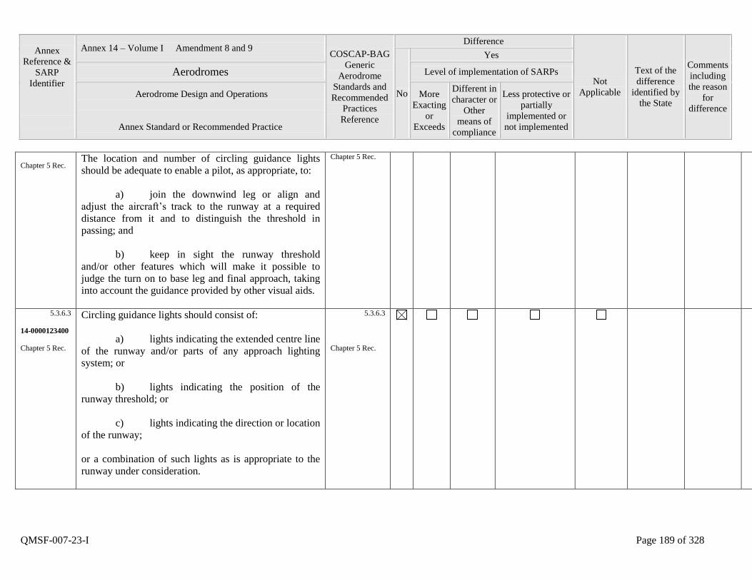
Annex
Reference &
SARP
Identifier
Annex 14 – Volume I Amendment 8 and 9 COSCAP-BAG
Generic
Aerodrome
Standards and
Recommended
Practices
Reference
Difference
Not
Applicable
Text of the
difference
identified by
the State
Comments
including
the reason
for
difference
No
Yes
Aerodromes Level of implementation of SARPs
Aerodrome Design and Operations
Annex Standard or Recommended Practice
More
Exacting
or
Exceeds
Different in
character or
Other
means of
compliance
Less protective or
partially
implemented or
not implemented
QMSF-007-23-I Page 189 of 328
Chapter 5 Rec. The location and number of circling guidance lights
should be adequate to enable a pilot, as appropriate, to:
a) join the downwind leg or align and
adjust the aircraft‟s track to the runway at a required
distance from it and to distinguish the threshold in
passing; and
b) keep in sight the runway threshold
and/or other features which will make it possible to
judge the turn on to base leg and final approach, taking
into account the guidance provided by other visual aids.
Chapter 5 Rec.
5.3.6.3
14-0000123400
Chapter 5 Rec.
Circling guidance lights should consist of:
a) lights indicating the extended centre line
of the runway and/or parts of any approach lighting
system; or
b) lights indicating the position of the
runway threshold; or
c) lights indicating the direction or location
of the runway;
or a combination of such lights as is appropriate to the
runway under consideration.
5.3.6.3
Chapter 5 Rec.
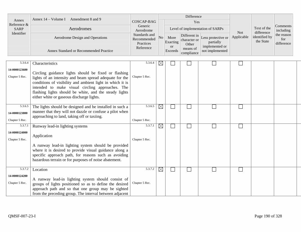
Annex
Reference &
SARP
Identifier
Annex 14 – Volume I Amendment 8 and 9 COSCAP-BAG
Generic
Aerodrome
Standards and
Recommended
Practices
Reference
Difference
Not
Applicable
Text of the
difference
identified by
the State
Comments
including
the reason
for
difference
No
Yes
Aerodromes Level of implementation of SARPs
Aerodrome Design and Operations
Annex Standard or Recommended Practice
More
Exacting
or
Exceeds
Different in
character or
Other
means of
compliance
Less protective or
partially
implemented or
not implemented
QMSF-007-23-I Page 190 of 328
5.3.6.4
14-0000123600
Chapter 5 Rec.
Characteristics
Circling guidance lights should be fixed or flashing
lights of an intensity and beam spread adequate for the
conditions of visibility and ambient light in which it is
intended to make visual circling approaches. The
flashing lights should be white, and the steady lights
either white or gaseous discharge lights.
5.3.6.4
Chapter 5 Rec.
5.3.6.5
14-0000123800
Chapter 5 Rec.
The lights should be designed and be installed in such a
manner that they will not dazzle or confuse a pilot when
approaching to land, taking off or taxiing.
5.3.6.5
Chapter 5 Rec.
5.3.7.1
14-0000124000
Chapter 5 Rec.
Runway lead-in lighting systems
Application
A runway lead-in lighting system should be provided
where it is desired to provide visual guidance along a
specific approach path, for reasons such as avoiding
hazardous terrain or for purposes of noise abatement.
5.3.7.1
Chapter 5 Rec.
5.3.7.2
14-0000124200
Chapter 5 Rec.
Location
A runway lead-in lighting system should consist of
groups of lights positioned so as to define the desired
approach path and so that one group may be sighted
from the preceding group. The interval between adjacent
5.3.7.2
Chapter 5 Rec.
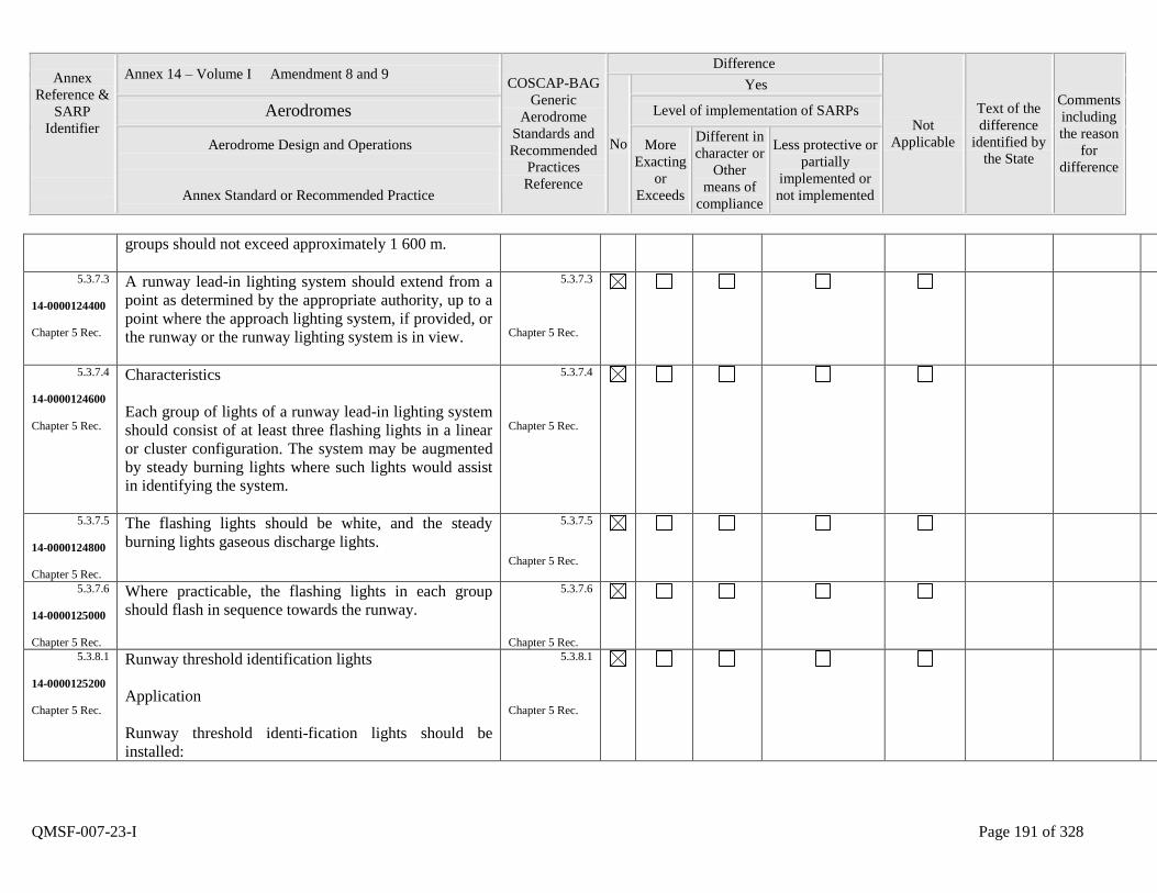
Annex
Reference &
SARP
Identifier
Annex 14 – Volume I Amendment 8 and 9 COSCAP-BAG
Generic
Aerodrome
Standards and
Recommended
Practices
Reference
Difference
Not
Applicable
Text of the
difference
identified by
the State
Comments
including
the reason
for
difference
No
Yes
Aerodromes Level of implementation of SARPs
Aerodrome Design and Operations
Annex Standard or Recommended Practice
More
Exacting
or
Exceeds
Different in
character or
Other
means of
compliance
Less protective or
partially
implemented or
not implemented
QMSF-007-23-I Page 191 of 328
groups should not exceed approximately 1 600 m.
5.3.7.3
14-0000124400
Chapter 5 Rec.
A runway lead-in lighting system should extend from a
point as determined by the appropriate authority, up to a
point where the approach lighting system, if provided, or
the runway or the runway lighting system is in view.
5.3.7.3
Chapter 5 Rec.
5.3.7.4
14-0000124600
Chapter 5 Rec.
Characteristics
Each group of lights of a runway lead-in lighting system
should consist of at least three flashing lights in a linear
or cluster configuration. The system may be augmented
by steady burning lights where such lights would assist
in identifying the system.
5.3.7.4
Chapter 5 Rec.
5.3.7.5
14-0000124800
Chapter 5 Rec.
The flashing lights should be white, and the steady
burning lights gaseous discharge lights.
5.3.7.5
Chapter 5 Rec.
5.3.7.6
14-0000125000
Chapter 5 Rec.
Where practicable, the flashing lights in each group
should flash in sequence towards the runway.
5.3.7.6
Chapter 5 Rec.
5.3.8.1
14-0000125200
Chapter 5 Rec.
Runway threshold identification lights
Application
Runway threshold identi-fication lights should be
installed:
5.3.8.1
Chapter 5 Rec.
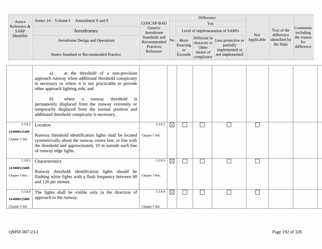
Annex
Reference &
SARP
Identifier
Annex 14 – Volume I Amendment 8 and 9 COSCAP-BAG
Generic
Aerodrome
Standards and
Recommended
Practices
Reference
Difference
Not
Applicable
Text of the
difference
identified by
the State
Comments
including
the reason
for
difference
No
Yes
Aerodromes Level of implementation of SARPs
Aerodrome Design and Operations
Annex Standard or Recommended Practice
More
Exacting
or
Exceeds
Different in
character or
Other
means of
compliance
Less protective or
partially
implemented or
not implemented
QMSF-007-23-I Page 192 of 328
a) at the threshold of a non-precision
approach runway when additional threshold conspicuity
is necessary or where it is not practicable to provide
other approach lighting aids; and
b) where a runway threshold is
permanently displaced from the runway extremity or
temporarily displaced from the normal position and
additional threshold conspicuity is necessary.
5.3.8.2
14-0000125400
Chapter 5 Std.
Location
Runway threshold identification lights shall be located
symmetrically about the runway centre line, in line with
the threshold and approximately 10 m outside each line
of runway edge lights.
5.3.8.2
Chapter 5 Std.
5.3.8.3
14-0000125600
Chapter 5 Rec.
Characteristics
Runway threshold identification lights should be
flashing white lights with a flash frequency between 60
and 120 per minute.
5.3.8.3
Chapter 5 Rec.
5.3.8.4
14-0000125800
Chapter 5 Std.
The lights shall be visible only in the direction of
approach to the runway.
5.3.8.4
Chapter 5 Std.

Annex
Reference &
SARP
Identifier
Annex 14 – Volume I Amendment 8 and 9 COSCAP-BAG
Generic
Aerodrome
Standards and
Recommended
Practices
Reference
Difference
Not
Applicable
Text of the
difference
identified by
the State
Comments
including
the reason
for
difference
No
Yes
Aerodromes Level of implementation of SARPs
Aerodrome Design and Operations
Annex Standard or Recommended Practice
More
Exacting
or
Exceeds
Different in
character or
Other
means of
compliance
Less protective or
partially
implemented or
not implemented
QMSF-007-23-I Page 193 of 328
5.3.9.1
14-0000126000
Chapter 5 Std.
Runway edge lights
Application
Runway edge lights shall be provided for a runway
intended for use at night or for a precision approach
runway intended for use by day or night.
5.3.9.1
Chapter 5 Std.
5.3.9.2
14-0000126200
Chapter 5 Rec.
Runway edge lights should be provided on a runway
intended for take-off with an operating minimum below
an RVR of the order of 800 m by day.
5.3.9.2
Chapter 5 Rec.
5.3.9.3
14-0000126400
Chapter 5 Std.
Location
Runway edge lights shall be placed along the full length
of the runway and shall be in two parallel rows
equidistant from the centre line.
5.3.9.3
Chapter 5 Std.
5.3.9.4
14-0000126600
Chapter 5 Std.
Runway edge lights shall be placed along the edges of
the area declared for use as the runway or outside the
edges of the area at a distance of not more than 3 m.
5.3.9.4
Chapter 5 Std.
5.3.9.5
14-0000126800
Chapter 5 Rec.
Where the width of the area which could be declared as
runway exceeds 60 m, the distance between the rows of
lights should be determined taking into account the
nature of the operations, the light distribution
characteristics of the runway edge lights, and other
visual aids serving the runway.
5.3.9.5
Chapter 5 Rec.
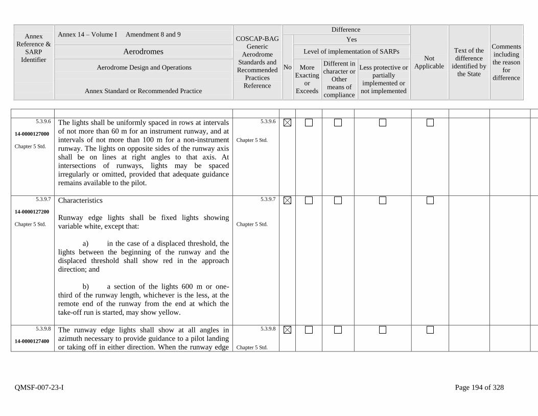
Annex
Reference &
SARP
Identifier
Annex 14 – Volume I Amendment 8 and 9 COSCAP-BAG
Generic
Aerodrome
Standards and
Recommended
Practices
Reference
Difference
Not
Applicable
Text of the
difference
identified by
the State
Comments
including
the reason
for
difference
No
Yes
Aerodromes Level of implementation of SARPs
Aerodrome Design and Operations
Annex Standard or Recommended Practice
More
Exacting
or
Exceeds
Different in
character or
Other
means of
compliance
Less protective or
partially
implemented or
not implemented
QMSF-007-23-I Page 194 of 328
5.3.9.6
14-0000127000
Chapter 5 Std.
The lights shall be uniformly spaced in rows at intervals
of not more than 60 m for an instrument runway, and at
intervals of not more than 100 m for a non-instrument
runway. The lights on opposite sides of the runway axis
shall be on lines at right angles to that axis. At
intersections of runways, lights may be spaced
irregularly or omitted, provided that adequate guidance
remains available to the pilot.
5.3.9.6
Chapter 5 Std.
5.3.9.7
14-0000127200
Chapter 5 Std.
Characteristics
Runway edge lights shall be fixed lights showing
variable white, except that:
a) in the case of a displaced threshold, the
lights between the beginning of the runway and the
displaced threshold shall show red in the approach
direction; and
b) a section of the lights 600 m or one-
third of the runway length, whichever is the less, at the
remote end of the runway from the end at which the
take-off run is started, may show yellow.
5.3.9.7
Chapter 5 Std.
5.3.9.8
14-0000127400
The runway edge lights shall show at all angles in
azimuth necessary to provide guidance to a pilot landing
or taking off in either direction. When the runway edge
5.3.9.8
Chapter 5 Std.
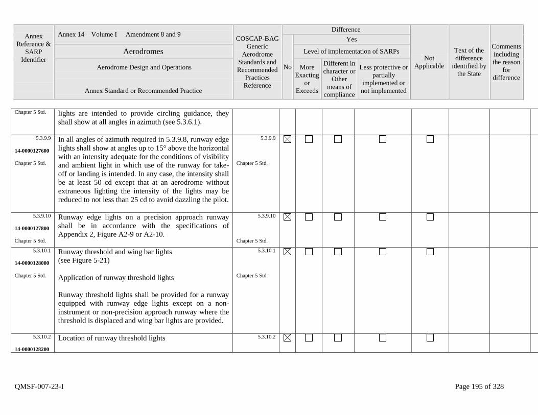
Annex
Reference &
SARP
Identifier
Annex 14 – Volume I Amendment 8 and 9 COSCAP-BAG
Generic
Aerodrome
Standards and
Recommended
Practices
Reference
Difference
Not
Applicable
Text of the
difference
identified by
the State
Comments
including
the reason
for
difference
No
Yes
Aerodromes Level of implementation of SARPs
Aerodrome Design and Operations
Annex Standard or Recommended Practice
More
Exacting
or
Exceeds
Different in
character or
Other
means of
compliance
Less protective or
partially
implemented or
not implemented
QMSF-007-23-I Page 195 of 328
Chapter 5 Std. lights are intended to provide circling guidance, they
shall show at all angles in azimuth (see 5.3.6.1).
5.3.9.9
14-0000127600
Chapter 5 Std.
In all angles of azimuth required in 5.3.9.8, runway edge
lights shall show at angles up to 15° above the horizontal
with an intensity adequate for the conditions of visibility
and ambient light in which use of the runway for take-
off or landing is intended. In any case, the intensity shall
be at least 50 cd except that at an aerodrome without
extraneous lighting the intensity of the lights may be
reduced to not less than 25 cd to avoid dazzling the pilot.
5.3.9.9
Chapter 5 Std.
5.3.9.10
14-0000127800
Chapter 5 Std.
Runway edge lights on a precision approach runway
shall be in accordance with the specifications of
Appendix 2, Figure A2-9 or A2-10.
5.3.9.10
Chapter 5 Std.
5.3.10.1
14-0000128000
Chapter 5 Std.
Runway threshold and wing bar lights
(see Figure 5-21)
Application of runway threshold lights
Runway threshold lights shall be provided for a runway
equipped with runway edge lights except on a non-
instrument or non-precision approach runway where the
threshold is displaced and wing bar lights are provided.
5.3.10.1
Chapter 5 Std.
5.3.10.2
14-0000128200
Location of runway threshold lights
5.3.10.2
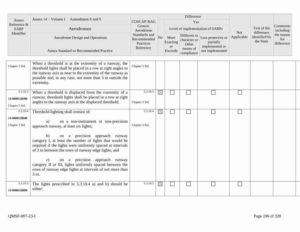
Annex
Reference &
SARP
Identifier
Annex 14 – Volume I Amendment 8 and 9 COSCAP-BAG
Generic
Aerodrome
Standards and
Recommended
Practices
Reference
Difference
Not
Applicable
Text of the
difference
identified by
the State
Comments
including
the reason
for
difference
No
Yes
Aerodromes Level of implementation of SARPs
Aerodrome Design and Operations
Annex Standard or Recommended Practice
More
Exacting
or
Exceeds
Different in
character or
Other
means of
compliance
Less protective or
partially
implemented or
not implemented
QMSF-007-23-I Page 196 of 328
Chapter 5 Std. When a threshold is at the extremity of a runway, the
threshold lights shall be placed in a row at right angles to
the runway axis as near to the extremity of the runway as
possible and, in any case, not more than 3 m outside the
extremity.
Chapter 5 Std.
5.3.10.3
14-0000128400
Chapter 5 Std.
When a threshold is displaced from the extremity of a
runway, threshold lights shall be placed in a row at right
angles to the runway axis at the displaced threshold.
5.3.10.3
Chapter 5 Std.
5.3.10.4
14-0000128600
Chapter 5 Std.
Threshold lighting shall consist of:
a) on a non-instrument or non-precision
approach runway, at least six lights;
b) on a precision approach runway
category I, at least the number of lights that would be
required if the lights were uniformly spaced at intervals
of 3 m between the rows of runway edge lights; and
c) on a precision approach runway
category II or III, lights uniformly spaced between the
rows of runway edge lights at intervals of not more than
3 m.
5.3.10.4
Chapter 5 Std.
5.3.10.5
14-0000128800
The lights prescribed in 5.3.10.4 a) and b) should be
either:
5.3.10.5
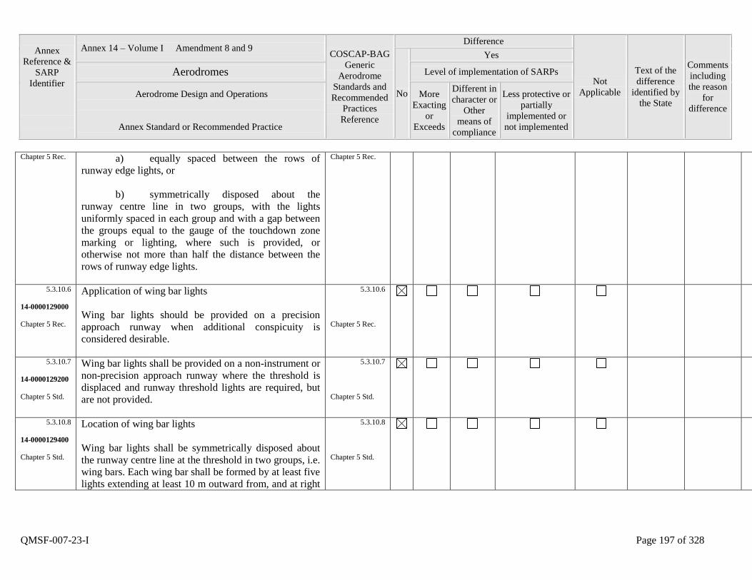
Annex
Reference &
SARP
Identifier
Annex 14 – Volume I Amendment 8 and 9 COSCAP-BAG
Generic
Aerodrome
Standards and
Recommended
Practices
Reference
Difference
Not
Applicable
Text of the
difference
identified by
the State
Comments
including
the reason
for
difference
No
Yes
Aerodromes Level of implementation of SARPs
Aerodrome Design and Operations
Annex Standard or Recommended Practice
More
Exacting
or
Exceeds
Different in
character or
Other
means of
compliance
Less protective or
partially
implemented or
not implemented
QMSF-007-23-I Page 197 of 328
Chapter 5 Rec. a) equally spaced between the rows of
runway edge lights, or
b) symmetrically disposed about the
runway centre line in two groups, with the lights
uniformly spaced in each group and with a gap between
the groups equal to the gauge of the touchdown zone
marking or lighting, where such is provided, or
otherwise not more than half the distance between the
rows of runway edge lights.
Chapter 5 Rec.
5.3.10.6
14-0000129000
Chapter 5 Rec.
Application of wing bar lights
Wing bar lights should be provided on a precision
approach runway when additional conspicuity is
considered desirable.
5.3.10.6
Chapter 5 Rec.
5.3.10.7
14-0000129200
Chapter 5 Std.
Wing bar lights shall be provided on a non-instrument or
non-precision approach runway where the threshold is
displaced and runway threshold lights are required, but
are not provided.
5.3.10.7
Chapter 5 Std.
5.3.10.8
14-0000129400
Chapter 5 Std.
Location of wing bar lights
Wing bar lights shall be symmetrically disposed about
the runway centre line at the threshold in two groups, i.e.
wing bars. Each wing bar shall be formed by at least five
lights extending at least 10 m outward from, and at right
5.3.10.8
Chapter 5 Std.
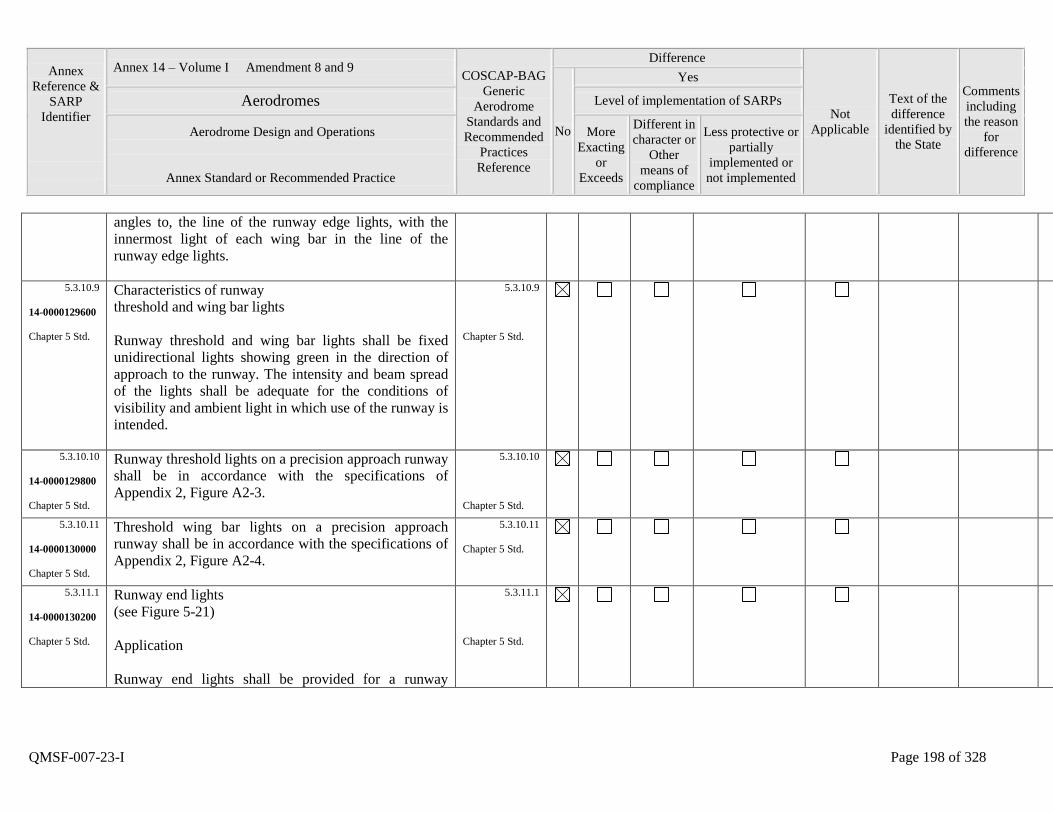
Annex
Reference &
SARP
Identifier
Annex 14 – Volume I Amendment 8 and 9 COSCAP-BAG
Generic
Aerodrome
Standards and
Recommended
Practices
Reference
Difference
Not
Applicable
Text of the
difference
identified by
the State
Comments
including
the reason
for
difference
No
Yes
Aerodromes Level of implementation of SARPs
Aerodrome Design and Operations
Annex Standard or Recommended Practice
More
Exacting
or
Exceeds
Different in
character or
Other
means of
compliance
Less protective or
partially
implemented or
not implemented
QMSF-007-23-I Page 198 of 328
angles to, the line of the runway edge lights, with the
innermost light of each wing bar in the line of the
runway edge lights.
5.3.10.9
14-0000129600
Chapter 5 Std.
Characteristics of runway
threshold and wing bar lights
Runway threshold and wing bar lights shall be fixed
unidirectional lights showing green in the direction of
approach to the runway. The intensity and beam spread
of the lights shall be adequate for the conditions of
visibility and ambient light in which use of the runway is
intended.
5.3.10.9
Chapter 5 Std.
5.3.10.10
14-0000129800
Chapter 5 Std.
Runway threshold lights on a precision approach runway
shall be in accordance with the specifications of
Appendix 2, Figure A2-3.
5.3.10.10
Chapter 5 Std.
5.3.10.11
14-0000130000
Chapter 5 Std.
Threshold wing bar lights on a precision approach
runway shall be in accordance with the specifications of
Appendix 2, Figure A2-4.
5.3.10.11
Chapter 5 Std.
5.3.11.1
14-0000130200
Chapter 5 Std.
Runway end lights
(see Figure 5-21)
Application
Runway end lights shall be provided for a runway
5.3.11.1
Chapter 5 Std.
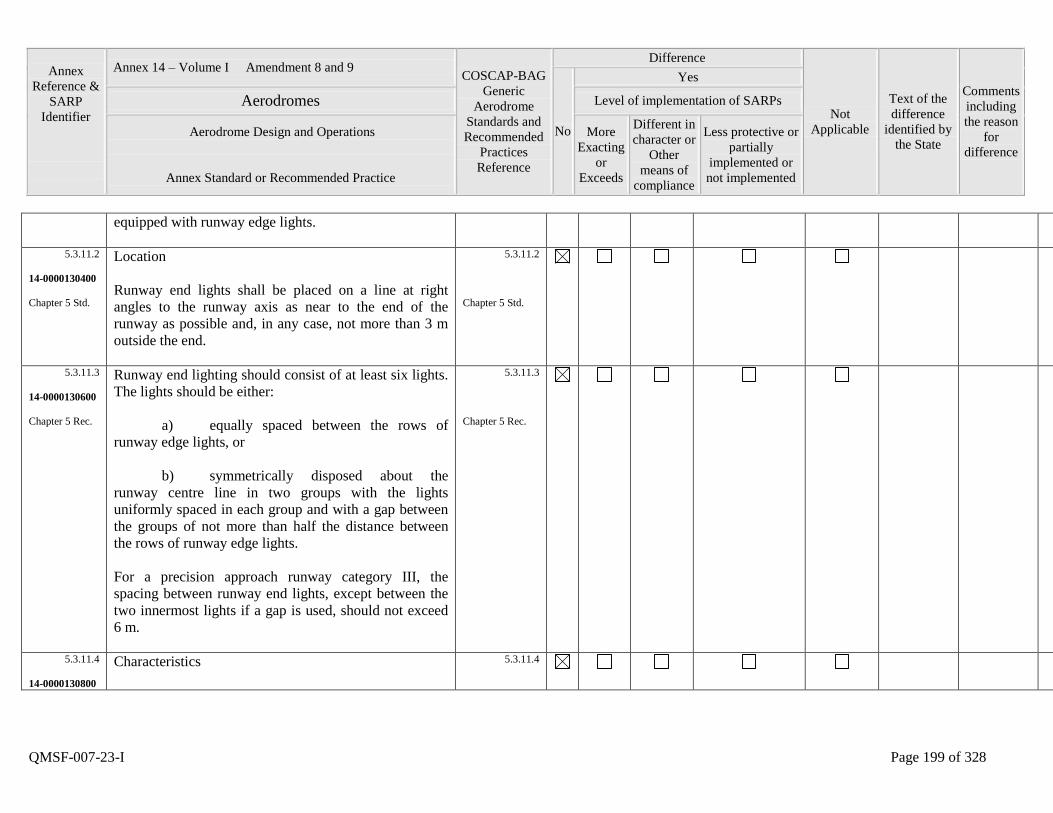
Annex
Reference &
SARP
Identifier
Annex 14 – Volume I Amendment 8 and 9 COSCAP-BAG
Generic
Aerodrome
Standards and
Recommended
Practices
Reference
Difference
Not
Applicable
Text of the
difference
identified by
the State
Comments
including
the reason
for
difference
No
Yes
Aerodromes Level of implementation of SARPs
Aerodrome Design and Operations
Annex Standard or Recommended Practice
More
Exacting
or
Exceeds
Different in
character or
Other
means of
compliance
Less protective or
partially
implemented or
not implemented
QMSF-007-23-I Page 199 of 328
equipped with runway edge lights.
5.3.11.2
14-0000130400
Chapter 5 Std.
Location
Runway end lights shall be placed on a line at right
angles to the runway axis as near to the end of the
runway as possible and, in any case, not more than 3 m
outside the end.
5.3.11.2
Chapter 5 Std.
5.3.11.3
14-0000130600
Chapter 5 Rec.
Runway end lighting should consist of at least six lights.
The lights should be either:
a) equally spaced between the rows of
runway edge lights, or
b) symmetrically disposed about the
runway centre line in two groups with the lights
uniformly spaced in each group and with a gap between
the groups of not more than half the distance between
the rows of runway edge lights.
For a precision approach runway category III, the
spacing between runway end lights, except between the
two innermost lights if a gap is used, should not exceed
6 m.
5.3.11.3
Chapter 5 Rec.
5.3.11.4
14-0000130800
Characteristics
5.3.11.4
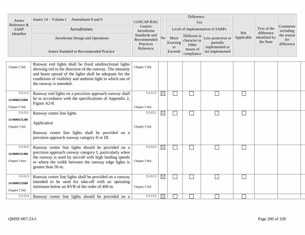
Annex
Reference &
SARP
Identifier
Annex 14 – Volume I Amendment 8 and 9 COSCAP-BAG
Generic
Aerodrome
Standards and
Recommended
Practices
Reference
Difference
Not
Applicable
Text of the
difference
identified by
the State
Comments
including
the reason
for
difference
No
Yes
Aerodromes Level of implementation of SARPs
Aerodrome Design and Operations
Annex Standard or Recommended Practice
More
Exacting
or
Exceeds
Different in
character or
Other
means of
compliance
Less protective or
partially
implemented or
not implemented
QMSF-007-23-I Page 200 of 328
Chapter 5 Std. Runway end lights shall be fixed unidirectional lights
showing red in the direction of the runway. The intensity
and beam spread of the lights shall be adequate for the
conditions of visibility and ambient light in which use of
the runway is intended.
Chapter 5 Std.
5.3.11.5
14-0000131000
Chapter 5 Std.
Runway end lights on a precision approach runway shall
be in accordance with the specifications of Appendix 2,
Figure A2-8.
5.3.11.5
Chapter 5 Std.
5.3.12.1
14-0000131200
Chapter 5 Std.
Runway centre line lights
Application
Runway centre line lights shall be provided on a
precision approach runway category II or III.
5.3.12.1
Chapter 5 Std.
5.3.12.2
14-0000131400
Chapter 5 Rec.
Runway centre line lights should be provided on a
precision approach runway category I, particularly when
the runway is used by aircraft with high landing speeds
or where the width between the runway edge lights is
greater than 50 m.
5.3.12.2
Chapter 5 Rec.
5.3.12.3
14-0000131600
Chapter 5 Std.
Runway centre line lights shall be provided on a runway
intended to be used for take-off with an operating
minimum below an RVR of the order of 400 m.
5.3.12.3
Chapter 5 Std.
5.3.12.4 Runway centre line lights should be provided on a 5.3.12.4
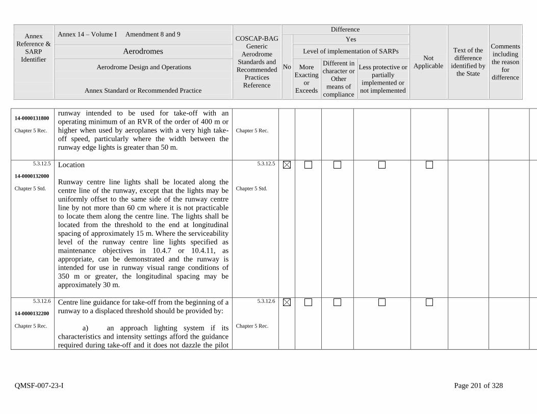
Annex
Reference &
SARP
Identifier
Annex 14 – Volume I Amendment 8 and 9 COSCAP-BAG
Generic
Aerodrome
Standards and
Recommended
Practices
Reference
Difference
Not
Applicable
Text of the
difference
identified by
the State
Comments
including
the reason
for
difference
No
Yes
Aerodromes Level of implementation of SARPs
Aerodrome Design and Operations
Annex Standard or Recommended Practice
More
Exacting
or
Exceeds
Different in
character or
Other
means of
compliance
Less protective or
partially
implemented or
not implemented
QMSF-007-23-I Page 201 of 328
14-0000131800
Chapter 5 Rec.
runway intended to be used for take-off with an
operating minimum of an RVR of the order of 400 m or
higher when used by aeroplanes with a very high take-
off speed, particularly where the width between the
runway edge lights is greater than 50 m.
Chapter 5 Rec.
5.3.12.5
14-0000132000
Chapter 5 Std.
Location
Runway centre line lights shall be located along the
centre line of the runway, except that the lights may be
uniformly offset to the same side of the runway centre
line by not more than 60 cm where it is not practicable
to locate them along the centre line. The lights shall be
located from the threshold to the end at longitudinal
spacing of approximately 15 m. Where the serviceability
level of the runway centre line lights specified as
maintenance objectives in 10.4.7 or 10.4.11, as
appropriate, can be demonstrated and the runway is
intended for use in runway visual range conditions of
350 m or greater, the longitudinal spacing may be
approximately 30 m.
5.3.12.5
Chapter 5 Std.
5.3.12.6
14-0000132200
Chapter 5 Rec.
Centre line guidance for take-off from the beginning of a
runway to a displaced threshold should be provided by:
a) an approach lighting system if its
characteristics and intensity settings afford the guidance
required during take-off and it does not dazzle the pilot
5.3.12.6
Chapter 5 Rec.
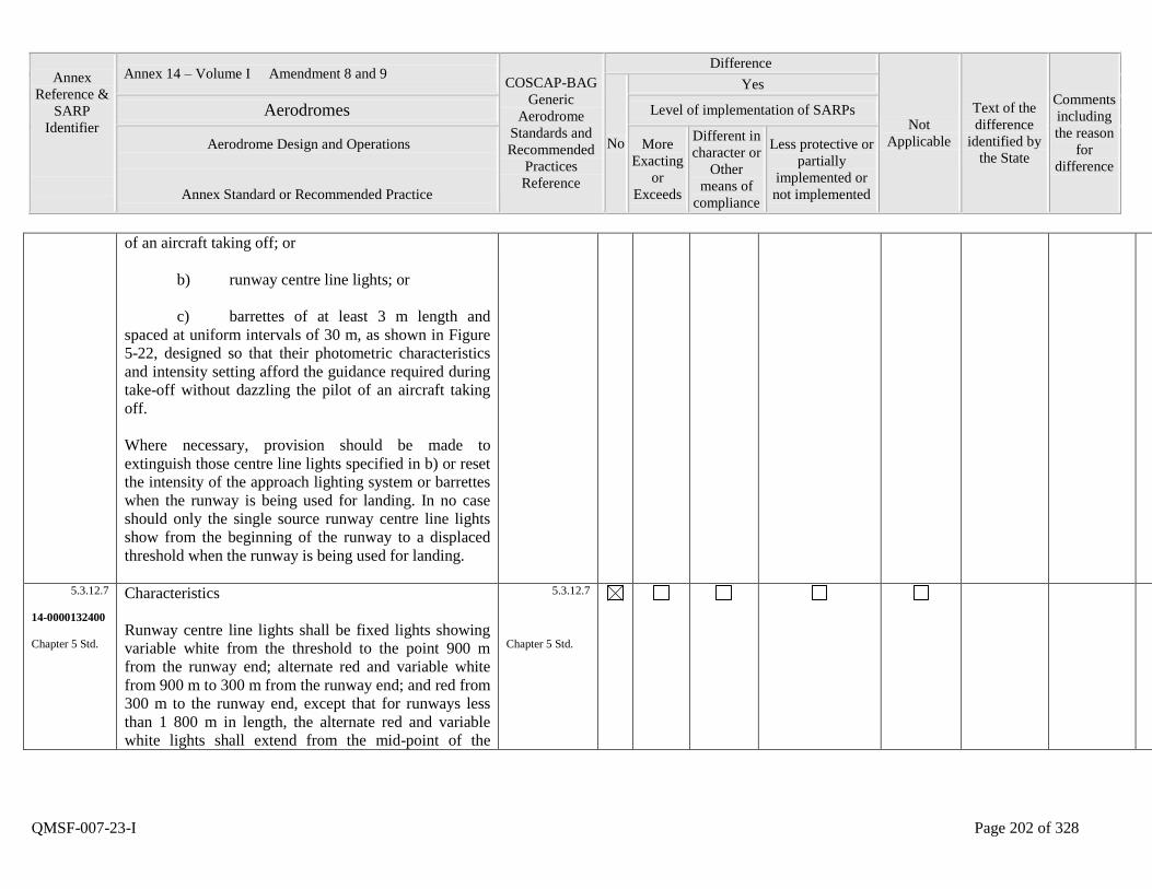
Annex
Reference &
SARP
Identifier
Annex 14 – Volume I Amendment 8 and 9 COSCAP-BAG
Generic
Aerodrome
Standards and
Recommended
Practices
Reference
Difference
Not
Applicable
Text of the
difference
identified by
the State
Comments
including
the reason
for
difference
No
Yes
Aerodromes Level of implementation of SARPs
Aerodrome Design and Operations
Annex Standard or Recommended Practice
More
Exacting
or
Exceeds
Different in
character or
Other
means of
compliance
Less protective or
partially
implemented or
not implemented
QMSF-007-23-I Page 202 of 328
of an aircraft taking off; or
b) runway centre line lights; or
c) barrettes of at least 3 m length and
spaced at uniform intervals of 30 m, as shown in Figure
5-22, designed so that their photometric characteristics
and intensity setting afford the guidance required during
take-off without dazzling the pilot of an aircraft taking
off.
Where necessary, provision should be made to
extinguish those centre line lights specified in b) or reset
the intensity of the approach lighting system or barrettes
when the runway is being used for landing. In no case
should only the single source runway centre line lights
show from the beginning of the runway to a displaced
threshold when the runway is being used for landing.
5.3.12.7
14-0000132400
Chapter 5 Std.
Characteristics
Runway centre line lights shall be fixed lights showing
variable white from the threshold to the point 900 m
from the runway end; alternate red and variable white
from 900 m to 300 m from the runway end; and red from
300 m to the runway end, except that for runways less
than 1 800 m in length, the alternate red and variable
white lights shall extend from the mid-point of the
5.3.12.7
Chapter 5 Std.

Annex
Reference &
SARP
Identifier
Annex 14 – Volume I Amendment 8 and 9 COSCAP-BAG
Generic
Aerodrome
Standards and
Recommended
Practices
Reference
Difference
Not
Applicable
Text of the
difference
identified by
the State
Comments
including
the reason
for
difference
No
Yes
Aerodromes Level of implementation of SARPs
Aerodrome Design and Operations
Annex Standard or Recommended Practice
More
Exacting
or
Exceeds
Different in
character or
Other
means of
compliance
Less protective or
partially
implemented or
not implemented
QMSF-007-23-I Page 203 of 328
runway usable for landing to 300 m from the runway
end.
5.3.12.8
14-0000132600
Chapter 5 Std.
Runway centre line lights shall be in accordance with the
specifications of Appendix 2, Figure A2-6 or A2-7.
5.3.12.8
Chapter 5 Std.
5.3.13.1
14-0000132800
Chapter 5 Std.
Runway touchdown zone lights
Application
Touchdown zone lights shall be provided in the
touchdown zone of a precision approach runway
category II or III.
5.3.13.1
Chapter 5 Std.
5.3.13.2
14-0000133000
Chapter 5 Std.
Location
Touchdown zone lights shall extend from the threshold
for a longitudinal distance of 900 m, except that, on
runways less than 1 800 m in length, the system shall be
shortened so that it does not extend beyond the midpoint
of the runway. The pattern shall be formed by pairs of
barrettes symmetrically located about the runway centre
line. The lateral spacing between the innermost lights of
a pair of barrettes shall be equal to the lateral spacing
selected for the touchdown zone marking. The
longitudinal spacing between pairs of barrettes shall be
either 30 m or 60 m.
5.3.13.2
Chapter 5 Std.

Annex
Reference &
SARP
Identifier
Annex 14 – Volume I Amendment 8 and 9 COSCAP-BAG
Generic
Aerodrome
Standards and
Recommended
Practices
Reference
Difference
Not
Applicable
Text of the
difference
identified by
the State
Comments
including
the reason
for
difference
No
Yes
Aerodromes Level of implementation of SARPs
Aerodrome Design and Operations
Annex Standard or Recommended Practice
More
Exacting
or
Exceeds
Different in
character or
Other
means of
compliance
Less protective or
partially
implemented or
not implemented
QMSF-007-23-I Page 204 of 328
5.3.13.3
14-0000133200
Chapter 5 Std.
Characteristics
A barrette shall be composed of at least three lights with
a spacing between the lights of not more than 1.5m.
5.3.13.3
Chapter 5 Std.
5.3.13.4
14-0000133400
Chapter 5 Rec.
A barrette should be not less than 3 m nor more than 4.5
m in length.
5.3.13.4
Chapter 5 Rec.
5.3.13.5
14-0000133600
Chapter 5 Std.
Touchdown zone lights shall be fixed unidirectional
lights showing variable white.
5.3.13.5
Chapter 5 Std.
5.3.13.6
14-0000133800
Chapter 5 Std.
Touchdown zone lights shall be in accordance with the
specifications of Appendix 2, Figure A2-5.
5.3.13.6
Chapter 5 Std.
5.3.14.1
14-0000134000
Chapter 5 Rec.
Rapid exit taxiway indicator lights
Application
Rapid exit taxiway indicator lights should be provided
on a runway intended for use in runway visual range
conditions less than a value of 350 m and/or where the
traffic density is heavy.
5.3.14.1
Chapter 5 Rec.
5.3.14.2
14-0000134200
Rapid exit taxiway indicator lights shall not be displayed
in the event of any lamp failure or other failure that
5.3.14.2
Annex
Reference &
SARP
Identifier
Annex 14 – Volume I Amendment 8 and 9 COSCAP-BAG
Generic
Aerodrome
Standards and
Recommended
Practices
Reference
Difference
Not
Applicable
Text of the
difference
identified by
the State
Comments
including
the reason
for
difference
No
Yes
Aerodromes Level of implementation of SARPs
Aerodrome Design and Operations
Annex Standard or Recommended Practice
More
Exacting
or
Exceeds
Different in
character or
Other
means of
compliance
Less protective or
partially
implemented or
not implemented
QMSF-007-23-I Page 205 of 328
Chapter 5 Std. prevents the display of the light pattern depicted in
Figure 523, in full.
Chapter 5 Std.
5.3.14.3
14-0000134400
Chapter 5 Std.
A set of rapid exit taxiway indicator lights shall be
located on the runway on the same side of the runway
centre line as the associated rapid exit taxiway, in the
configuration shown in Figure 5-23. In each set, the
lights shall be located 2 m apart and the light nearest to
the runway centre line shall be displaced 2 m from the
runway centre line.
5.3.14.3
Chapter 5 Std.
5.3.14.4
14-0000134600
Chapter 5 Std.
Where more than one rapid exit taxiway exists on a
runway, the set of rapid exit taxiway indicator lights for
each exit shall not overlap when displayed.
5.3.14.4
Chapter 5 Std.
5.3.14.5
14-0000134800
Chapter 5 Std.
Characteristics
Rapid exit taxiway indicator lights shall be fixed
unidirectional yellow lights, aligned so as to be visible to
the pilot of a landing aeroplane in the direction of
approach to the runway.
5.3.14.5
Chapter 5 Std.
5.3.14.6
14-0000135000
Chapter 5 Std.
Rapid exit taxiway indicator lights shall be in
accordance with the specifications in Appendix 2, Figure
A26 or Figure A2-7, as appropriate.
5.3.14.6
Chapter 5 Std.
5.3.14.7
14-0000135200
Rapid exit taxiway indicator lights should be supplied
with power on a separate circuit to other runway lighting
5.3.14.7
Annex
Reference &
SARP
Identifier
Annex 14 – Volume I Amendment 8 and 9 COSCAP-BAG
Generic
Aerodrome
Standards and
Recommended
Practices
Reference
Difference
Not
Applicable
Text of the
difference
identified by
the State
Comments
including
the reason
for
difference
No
Yes
Aerodromes Level of implementation of SARPs
Aerodrome Design and Operations
Annex Standard or Recommended Practice
More
Exacting
or
Exceeds
Different in
character or
Other
means of
compliance
Less protective or
partially
implemented or
not implemented
QMSF-007-23-I Page 206 of 328
Chapter 5 Rec. so that they may be used when other lighting is switched
off.
Chapter 5 Rec.
5.3.15.1
14-0000135400
Chapter 5 Std.
Stopway lights
Application
Stopway lights shall be provided for a stopway intended
for use at night.
5.3.15.1
Chapter 5 Std.
5.3.15.2
14-0000135600
Chapter 5 Std.
Location
Stopway lights shall be placed along the full length of
the stopway and shall be in two parallel rows that are
equidistant from the centre line and coincident with the
rows of the runway edge lights. Stopway lights shall also
be provided across the end of a stopway on a line at right
angles to the stopway axis as near to the end of the
stopway as possible and, in any case, not more than 3 m
outside the end.
5.3.15.2
Chapter 5 Std.
5.3.15.3
14-0000135800
Chapter 5 Std.
Characteristics
Stopway lights shall be fixed unidirectional lights
showing red in the direction of the runway.
5.3.15.3
Chapter 5 Std.
5.3.16.1
14-0000136000
Taxiway centre line lights
5.3.16.1

Annex
Reference &
SARP
Identifier
Annex 14 – Volume I Amendment 8 and 9 COSCAP-BAG
Generic
Aerodrome
Standards and
Recommended
Practices
Reference
Difference
Not
Applicable
Text of the
difference
identified by
the State
Comments
including
the reason
for
difference
No
Yes
Aerodromes Level of implementation of SARPs
Aerodrome Design and Operations
Annex Standard or Recommended Practice
More
Exacting
or
Exceeds
Different in
character or
Other
means of
compliance
Less protective or
partially
implemented or
not implemented
QMSF-007-23-I Page 207 of 328
Chapter 5 Std. Application
Taxiway centre line lights shall be provided on an exit
taxiway, taxiway, de-icing/anti-icing facility and apron
intended for use in runway visual range conditions less
than a value of 350 m in such a manner as to provide
continuous guidance between the runway centre line and
aircraft stands, except that these lights need not be
provided where the traffic density is light and taxiway
edge lights and centre line marking provide adequate
guidance.
Chapter 5 Std.
5.3.16.2
14-0000136200
Chapter 5 Rec.
Taxiway centre line lights should be provided on a
taxiway intended for use at night in runway visual range
conditions of 350 m or greater, and particularly on
complex taxiway intersections and exit taxiways, except
that these lights need not be provided where the traffic
density is light and taxiway edge lights and centre line
marking provide adequate guidance.
5.3.16.2
Chapter 5 Rec.
5.3.16.3
14-0000136400
Chapter 5 Rec.
Taxiway centre line lights should be provided on an exit
taxiway, taxiway, de-icing/anti-icing facility and apron
in all visibility conditions where specified as
components of an advanced surface movement guidance
and control system in such a manner as to provide
continuous guidance between the runway centre line and
aircraft stands.
5.3.16.3
Chapter 5 Rec.
Annex
Reference &
SARP
Identifier
Annex 14 – Volume I Amendment 8 and 9 COSCAP-BAG
Generic
Aerodrome
Standards and
Recommended
Practices
Reference
Difference
Not
Applicable
Text of the
difference
identified by
the State
Comments
including
the reason
for
difference
No
Yes
Aerodromes Level of implementation of SARPs
Aerodrome Design and Operations
Annex Standard or Recommended Practice
More
Exacting
or
Exceeds
Different in
character or
Other
means of
compliance
Less protective or
partially
implemented or
not implemented
QMSF-007-23-I Page 208 of 328
5.3.16.4
14-0000136600
Chapter 5 Std.
Taxiway centre line lights shall be provided on a runway
forming part of a standard taxi-route and intended for
taxiing in runway visual range conditions less than a
value of 350 m, except that these lights need not be
provided where the traffic density is light and taxiway
edge lights and centre line marking provide adequate
guidance.
5.3.16.4
Chapter 5 Std.
5.3.16.5
14-0000136800
Chapter 5 Rec.
Taxiway centre line lights should be provided in all
visibility conditions on a runway forming part of a
standard taxi-route where specified as components of an
advanced surface movement guidance and control
system.
5.3.16.5
Chapter 5 Rec.
5.3.16.6
14-0000137000
Chapter 5 Std.
Characteristics
Taxiway centre line lights on a taxiway other than an
exit taxiway and on a runway forming part of a standard
taxi-route shall be fixed lights showing green with beam
dimensions such that the light is visible only from
aeroplanes on or in the vicinity of the taxiway.
5.3.16.6
Chapter 5 Std.
5.3.16.7
14-0000137200
Chapter 5 Std.
Taxiway centre line lights on an exit taxiway shall be
fixed lights. Alternate taxiway centre line lights shall
show green and yellow from their beginning near the
runway centre line to the perimeter of the ILS/MLS
critical/sensitive area or the lower edge of the inner
transitional surface, whichever is farthest from the
5.3.16.7
Chapter 5 Std.
Annex
Reference &
SARP
Identifier
Annex 14 – Volume I Amendment 8 and 9 COSCAP-BAG
Generic
Aerodrome
Standards and
Recommended
Practices
Reference
Difference
Not
Applicable
Text of the
difference
identified by
the State
Comments
including
the reason
for
difference
No
Yes
Aerodromes Level of implementation of SARPs
Aerodrome Design and Operations
Annex Standard or Recommended Practice
More
Exacting
or
Exceeds
Different in
character or
Other
means of
compliance
Less protective or
partially
implemented or
not implemented
QMSF-007-23-I Page 209 of 328
runway; and thereafter all lights shall show green
(Figure 5-24). The light nearest to the perimeter shall
always show yellow. Where aircraft may follow the
same centre line in both directions, all the centre line
lights shall show green to aircraft approaching the
runway.
5.3.16.8
14-0000137400
Chapter 5 Std.
Taxiway centre line lights shall be in accordance with
the specifications of:
a) Appendix 2, Figure A2-12, A2-13, or
A2-14 for taxiways intended for use in runway visual
range conditions of less than a value of 350 m; and
b) Appendix 2, Figure A2-15 or A2-16 for
other taxiways.
5.3.16.8
Chapter 5 Std.
5.3.16.9
14-0000137600
Chapter 5 Rec.
Where higher intensities are required, from an
operational point of view, taxiway centre line lights on
rapid exit taxiways intended for use in runway visual
range conditions less than a value of 350m should be in
accordance with the specifications of Appendix 2,
Figure A2-12. The number of levels of brilliancy
settings for these lights should be the same as that for the
runway centre line lights.
5.3.16.9
Chapter 5 Rec.
5.3.16.10
14-0000137800
Where taxiway centre line lights are specified as
components of an advanced surface movement guidance
5.3.16.10

Annex
Reference &
SARP
Identifier
Annex 14 – Volume I Amendment 8 and 9 COSCAP-BAG
Generic
Aerodrome
Standards and
Recommended
Practices
Reference
Difference
Not
Applicable
Text of the
difference
identified by
the State
Comments
including
the reason
for
difference
No
Yes
Aerodromes Level of implementation of SARPs
Aerodrome Design and Operations
Annex Standard or Recommended Practice
More
Exacting
or
Exceeds
Different in
character or
Other
means of
compliance
Less protective or
partially
implemented or
not implemented
QMSF-007-23-I Page 210 of 328
Chapter 5 Rec. and control system and where, from an operational point
of view, higher intensities are required to maintain
ground movements at a certain speed in very low
visibilities or in bright daytime conditions, taxiway
centre line lights should be in accordance with the
specifications of Appendix 2, Figure A2-17, A2-18 or
A2-19.
Chapter 5 Rec.
5.3.16.11
14-0000138000
Chapter 5 Rec.
Location
Taxiway centre line lights should normally be located on
the taxiway centre line marking, except that they may be
offset by not more than 30cm where it is not practicable
to locate them on the marking.
5.3.16.11
Chapter 5 Rec.
5.3.16.12
14-0000138200
Chapter 5 Rec.
Taxiway centre line lights on taxiways
Location
Taxiway centre line lights on a straight section of a
taxiway should be spaced at longitudinal intervals of not
more than 30 m, except that:
a) larger intervals not exceeding 60 m may
be used where, because of the prevailing meteorological
conditions, adequate guidance is provided by such
spacing;
5.3.16.12
Chapter 5 Std.
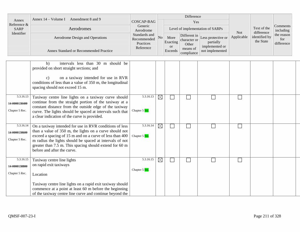
Annex
Reference &
SARP
Identifier
Annex 14 – Volume I Amendment 8 and 9 COSCAP-BAG
Generic
Aerodrome
Standards and
Recommended
Practices
Reference
Difference
Not
Applicable
Text of the
difference
identified by
the State
Comments
including
the reason
for
difference
No
Yes
Aerodromes Level of implementation of SARPs
Aerodrome Design and Operations
Annex Standard or Recommended Practice
More
Exacting
or
Exceeds
Different in
character or
Other
means of
compliance
Less protective or
partially
implemented or
not implemented
QMSF-007-23-I Page 211 of 328
b) intervals less than 30 m should be
provided on short straight sections; and
c) on a taxiway intended for use in RVR
conditions of less than a value of 350 m, the longitudinal
spacing should not exceed 15 m.
5.3.16.13
14-0000138400
Chapter 5 Rec.
Taxiway centre line lights on a taxiway curve should
continue from the straight portion of the taxiway at a
constant distance from the outside edge of the taxiway
curve. The lights should be spaced at intervals such that
a clear indication of the curve is provided.
5.3.16.13
Chapter 5 Std.
5.3.16.14
14-0000138600
Chapter 5 Rec.
On a taxiway intended for use in RVR conditions of less
than a value of 350 m, the lights on a curve should not
exceed a spacing of 15 m and on a curve of less than 400
m radius the lights should be spaced at intervals of not
greater than 7.5 m. This spacing should extend for 60 m
before and after the curve.
5.3.16.14
Chapter 5 Std.
5.3.16.15
14-0000138800
Chapter 5 Rec.
Taxiway centre line lights
on rapid exit taxiways
Location
Taxiway centre line lights on a rapid exit taxiway should
commence at a point at least 60 m before the beginning
of the taxiway centre line curve and continue beyond the
5.3.16.15
Chapter 5 Std.
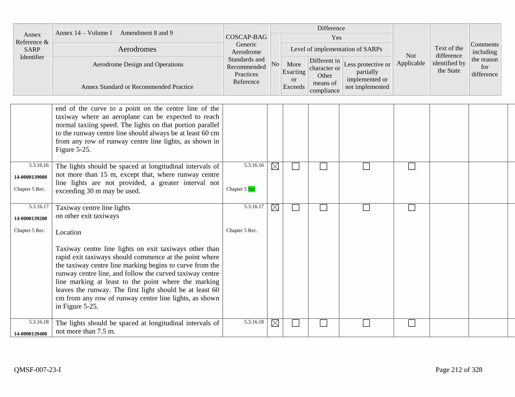
Annex
Reference &
SARP
Identifier
Annex 14 – Volume I Amendment 8 and 9 COSCAP-BAG
Generic
Aerodrome
Standards and
Recommended
Practices
Reference
Difference
Not
Applicable
Text of the
difference
identified by
the State
Comments
including
the reason
for
difference
No
Yes
Aerodromes Level of implementation of SARPs
Aerodrome Design and Operations
Annex Standard or Recommended Practice
More
Exacting
or
Exceeds
Different in
character or
Other
means of
compliance
Less protective or
partially
implemented or
not implemented
QMSF-007-23-I Page 212 of 328
end of the curve to a point on the centre line of the
taxiway where an aeroplane can be expected to reach
normal taxiing speed. The lights on that portion parallel
to the runway centre line should always be at least 60 cm
from any row of runway centre line lights, as shown in
Figure 5-25.
5.3.16.16
14-0000139000
Chapter 5 Rec.
The lights should be spaced at longitudinal intervals of
not more than 15 m, except that, where runway centre
line lights are not provided, a greater interval not
exceeding 30 m may be used.
5.3.16.16
Chapter 5 Std.
5.3.16.17
14-0000139200
Chapter 5 Rec.
Taxiway centre line lights
on other exit taxiways
Location
Taxiway centre line lights on exit taxiways other than
rapid exit taxiways should commence at the point where
the taxiway centre line marking begins to curve from the
runway centre line, and follow the curved taxiway centre
line marking at least to the point where the marking
leaves the runway. The first light should be at least 60
cm from any row of runway centre line lights, as shown
in Figure 5-25.
5.3.16.17
Chapter 5 Rec.
5.3.16.18
14-0000139400
The lights should be spaced at longitudinal intervals of
not more than 7.5 m.
5.3.16.18
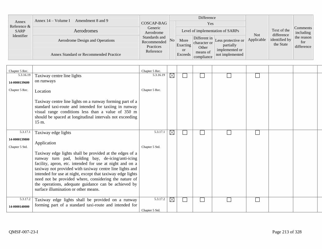
Annex
Reference &
SARP
Identifier
Annex 14 – Volume I Amendment 8 and 9 COSCAP-BAG
Generic
Aerodrome
Standards and
Recommended
Practices
Reference
Difference
Not
Applicable
Text of the
difference
identified by
the State
Comments
including
the reason
for
difference
No
Yes
Aerodromes Level of implementation of SARPs
Aerodrome Design and Operations
Annex Standard or Recommended Practice
More
Exacting
or
Exceeds
Different in
character or
Other
means of
compliance
Less protective or
partially
implemented or
not implemented
QMSF-007-23-I Page 213 of 328
Chapter 5 Rec.
Chapter 5 Rec.
5.3.16.19
14-0000139600
Chapter 5 Rec.
Taxiway centre line lights
on runways
Location
Taxiway centre line lights on a runway forming part of a
standard taxi-route and intended for taxiing in runway
visual range conditions less than a value of 350 m
should be spaced at longitudinal intervals not exceeding
15 m.
5.3.16.19
Chapter 5 Rec.
5.3.17.1
14-0000139800
Chapter 5 Std.
Taxiway edge lights
Application
Taxiway edge lights shall be provided at the edges of a
runway turn pad, holding bay, de-icing/anti-icing
facility, apron, etc. intended for use at night and on a
taxiway not provided with taxiway centre line lights and
intended for use at night, except that taxiway edge lights
need not be provided where, considering the nature of
the operations, adequate guidance can be achieved by
surface illumination or other means.
5.3.17.1
Chapter 5 Std.
5.3.17.2
14-0000140000
Taxiway edge lights shall be provided on a runway
forming part of a standard taxi-route and intended for
5.3.17.2
Chapter 5 Std.
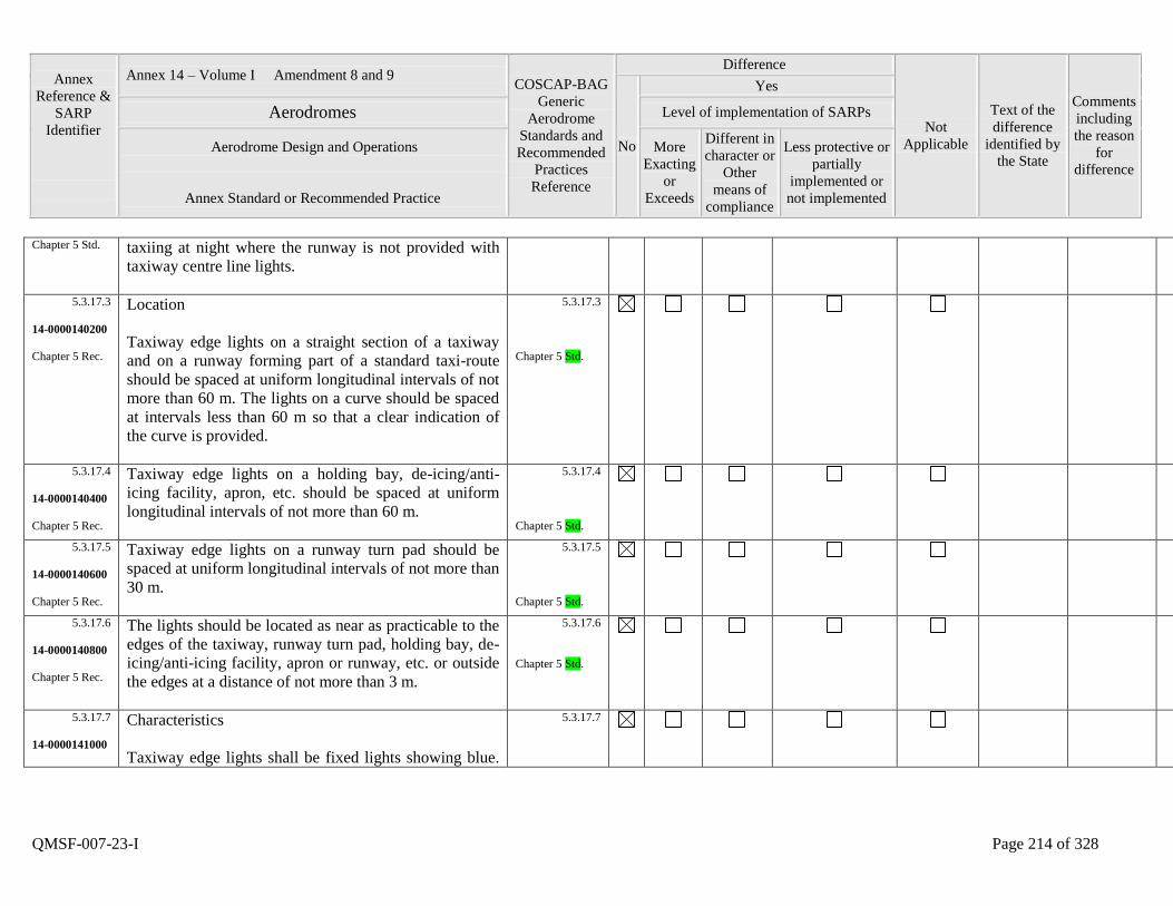
Annex
Reference &
SARP
Identifier
Annex 14 – Volume I Amendment 8 and 9 COSCAP-BAG
Generic
Aerodrome
Standards and
Recommended
Practices
Reference
Difference
Not
Applicable
Text of the
difference
identified by
the State
Comments
including
the reason
for
difference
No
Yes
Aerodromes Level of implementation of SARPs
Aerodrome Design and Operations
Annex Standard or Recommended Practice
More
Exacting
or
Exceeds
Different in
character or
Other
means of
compliance
Less protective or
partially
implemented or
not implemented
QMSF-007-23-I Page 214 of 328
Chapter 5 Std. taxiing at night where the runway is not provided with
taxiway centre line lights.
5.3.17.3
14-0000140200
Chapter 5 Rec.
Location
Taxiway edge lights on a straight section of a taxiway
and on a runway forming part of a standard taxi-route
should be spaced at uniform longitudinal intervals of not
more than 60 m. The lights on a curve should be spaced
at intervals less than 60 m so that a clear indication of
the curve is provided.
5.3.17.3
Chapter 5 Std.
5.3.17.4
14-0000140400
Chapter 5 Rec.
Taxiway edge lights on a holding bay, de-icing/anti-
icing facility, apron, etc. should be spaced at uniform
longitudinal intervals of not more than 60 m.
5.3.17.4
Chapter 5 Std.
5.3.17.5
14-0000140600
Chapter 5 Rec.
Taxiway edge lights on a runway turn pad should be
spaced at uniform longitudinal intervals of not more than
30 m.
5.3.17.5
Chapter 5 Std.
5.3.17.6
14-0000140800
Chapter 5 Rec.
The lights should be located as near as practicable to the
edges of the taxiway, runway turn pad, holding bay, de-
icing/anti-icing facility, apron or runway, etc. or outside
the edges at a distance of not more than 3 m.
5.3.17.6
Chapter 5 Std.
5.3.17.7
14-0000141000
Characteristics
Taxiway edge lights shall be fixed lights showing blue.
5.3.17.7
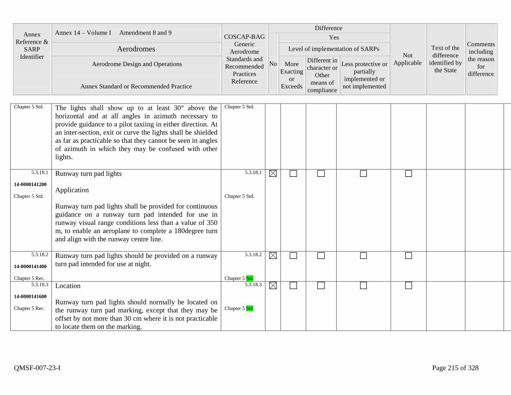
Annex
Reference &
SARP
Identifier
Annex 14 – Volume I Amendment 8 and 9 COSCAP-BAG
Generic
Aerodrome
Standards and
Recommended
Practices
Reference
Difference
Not
Applicable
Text of the
difference
identified by
the State
Comments
including
the reason
for
difference
No
Yes
Aerodromes Level of implementation of SARPs
Aerodrome Design and Operations
Annex Standard or Recommended Practice
More
Exacting
or
Exceeds
Different in
character or
Other
means of
compliance
Less protective or
partially
implemented or
not implemented
QMSF-007-23-I Page 215 of 328
Chapter 5 Std. The lights shall show up to at least 30° above the
horizontal and at all angles in azimuth necessary to
provide guidance to a pilot taxiing in either direction. At
an inter-section, exit or curve the lights shall be shielded
as far as practicable so that they cannot be seen in angles
of azimuth in which they may be confused with other
lights.
Chapter 5 Std.
5.3.18.1
14-0000141200
Chapter 5 Std.
Runway turn pad lights
Application
Runway turn pad lights shall be provided for continuous
guidance on a runway turn pad intended for use in
runway visual range conditions less than a value of 350
m, to enable an aeroplane to complete a 180degree turn
and align with the runway centre line.
5.3.18.1
Chapter 5 Std.
5.3.18.2
14-0000141400
Chapter 5 Rec.
Runway turn pad lights should be provided on a runway
turn pad intended for use at night.
5.3.18.2
Chapter 5 Std.
5.3.18.3
14-0000141600
Chapter 5 Rec.
Location
Runway turn pad lights should normally be located on
the runway turn pad marking, except that they may be
offset by not more than 30 cm where it is not practicable
to locate them on the marking.
5.3.18.3
Chapter 5 Std.
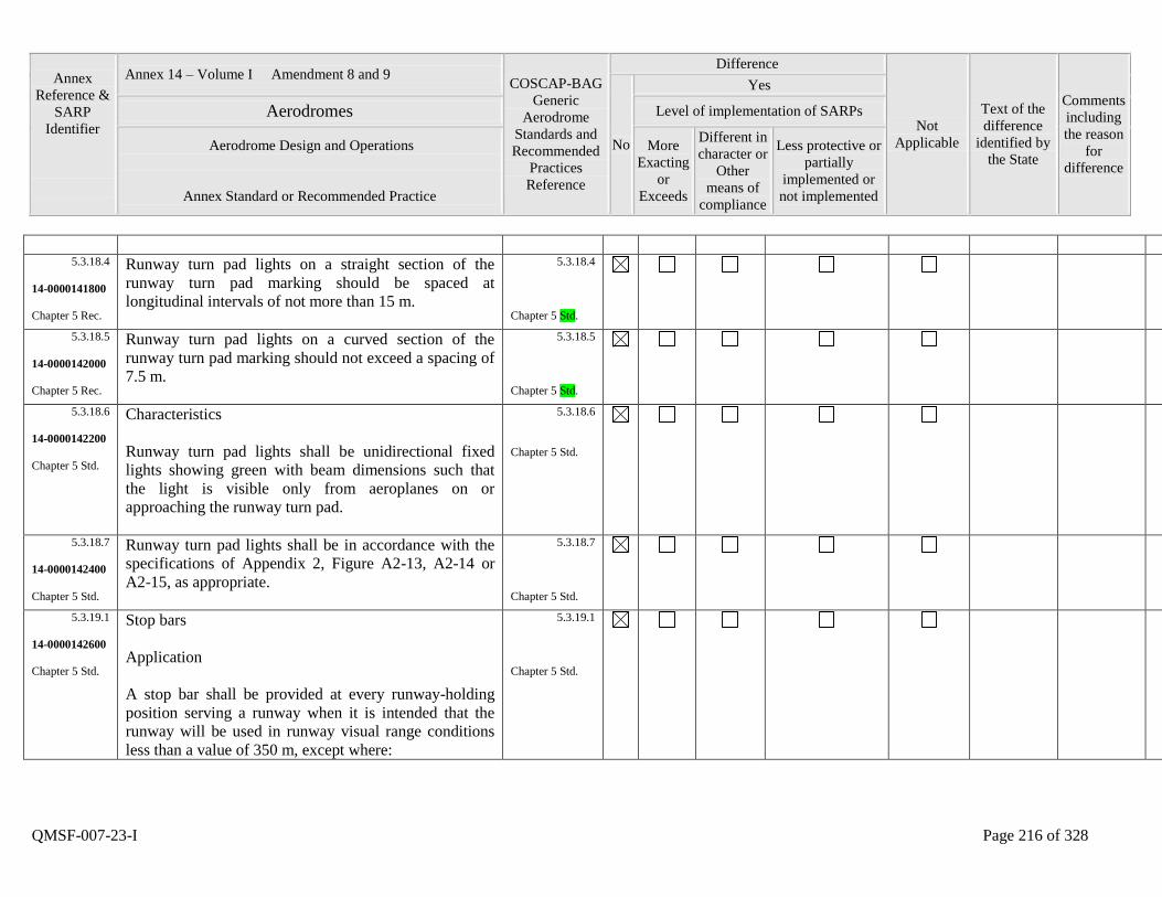
Annex
Reference &
SARP
Identifier
Annex 14 – Volume I Amendment 8 and 9 COSCAP-BAG
Generic
Aerodrome
Standards and
Recommended
Practices
Reference
Difference
Not
Applicable
Text of the
difference
identified by
the State
Comments
including
the reason
for
difference
No
Yes
Aerodromes Level of implementation of SARPs
Aerodrome Design and Operations
Annex Standard or Recommended Practice
More
Exacting
or
Exceeds
Different in
character or
Other
means of
compliance
Less protective or
partially
implemented or
not implemented
QMSF-007-23-I Page 216 of 328
5.3.18.4
14-0000141800
Chapter 5 Rec.
Runway turn pad lights on a straight section of the
runway turn pad marking should be spaced at
longitudinal intervals of not more than 15 m.
5.3.18.4
Chapter 5 Std.
5.3.18.5
14-0000142000
Chapter 5 Rec.
Runway turn pad lights on a curved section of the
runway turn pad marking should not exceed a spacing of
7.5 m.
5.3.18.5
Chapter 5 Std.
5.3.18.6
14-0000142200
Chapter 5 Std.
Characteristics
Runway turn pad lights shall be unidirectional fixed
lights showing green with beam dimensions such that
the light is visible only from aeroplanes on or
approaching the runway turn pad.
5.3.18.6
Chapter 5 Std.
5.3.18.7
14-0000142400
Chapter 5 Std.
Runway turn pad lights shall be in accordance with the
specifications of Appendix 2, Figure A2-13, A2-14 or
A2-15, as appropriate.
5.3.18.7
Chapter 5 Std.
5.3.19.1
14-0000142600
Chapter 5 Std.
Stop bars
Application
A stop bar shall be provided at every runway-holding
position serving a runway when it is intended that the
runway will be used in runway visual range conditions
less than a value of 350 m, except where:
5.3.19.1
Chapter 5 Std.
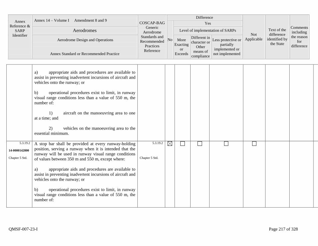
Annex
Reference &
SARP
Identifier
Annex 14 – Volume I Amendment 8 and 9 COSCAP-BAG
Generic
Aerodrome
Standards and
Recommended
Practices
Reference
Difference
Not
Applicable
Text of the
difference
identified by
the State
Comments
including
the reason
for
difference
No
Yes
Aerodromes Level of implementation of SARPs
Aerodrome Design and Operations
Annex Standard or Recommended Practice
More
Exacting
or
Exceeds
Different in
character or
Other
means of
compliance
Less protective or
partially
implemented or
not implemented
QMSF-007-23-I Page 217 of 328
a) appropriate aids and procedures are available to
assist in preventing inadvertent incursions of aircraft and
vehicles onto the runway; or
b) operational procedures exist to limit, in runway
visual range conditions less than a value of 550 m, the
number of:
1) aircraft on the manoeuvring area to one
at a time; and
2) vehicles on the manoeuvring area to the
essential minimum.
5.3.19.2
14-0000142800
Chapter 5 Std.
A stop bar shall be provided at every runway-holding
position, serving a runway when it is intended that the
runway will be used in runway visual range conditions
of values between 350 m and 550 m, except where:
a) appropriate aids and procedures are available to
assist in preventing inadvertent incursions of aircraft and
vehicles onto the runway; or
b) operational procedures exist to limit, in runway
visual range conditions less than a value of 550 m, the
number of:
5.3.19.2
Chapter 5 Std.

Annex
Reference &
SARP
Identifier
Annex 14 – Volume I Amendment 8 and 9 COSCAP-BAG
Generic
Aerodrome
Standards and
Recommended
Practices
Reference
Difference
Not
Applicable
Text of the
difference
identified by
the State
Comments
including
the reason
for
difference
No
Yes
Aerodromes Level of implementation of SARPs
Aerodrome Design and Operations
Annex Standard or Recommended Practice
More
Exacting
or
Exceeds
Different in
character or
Other
means of
compliance
Less protective or
partially
implemented or
not implemented
QMSF-007-23-I Page 218 of 328
1) aircraft on the manoeuvring area to one
at a time; and
2) vehicles on the manoeuvring area to the
essential minimum.
5.3.19.3
14-0000143000
Chapter 5 Rec.
A stop bar should be provided at an intermediate holding
position when it is desired to supplement markings with
lights and to provide traffic control by visual means.
5.3.19.3
Chapter 5 Std.
5.3.19.4
14-0000143200
Chapter 5 Rec.
Where the normal stop bar lights might be obscured
(from a pilot‟s view), for example, by snow or rain, or
where a pilot may be required to stop the aircraft in a
position so close to the lights that they are blocked from
view by the structure of the aircraft, then a pair of
elevated lights should be added to each end of the stop
bar.
5.3.19.4
Chapter 5 Rec.
5.3.19.5
14-0000143400
Chapter 5 Std.
Location
Stop bars shall be located across the taxiway at the point
where it is desired that traffic stop. Where the additional
lights specified in 5.3.19.4 are provided, these lights
shall be located not less than 3 m from the taxiway edge.
5.3.19.5
Chapter 5 Std.
5.3.19.6
14-0000143600
Characteristics
Stop bars shall consist of lights spaced at intervals of 3
5.3.19.6
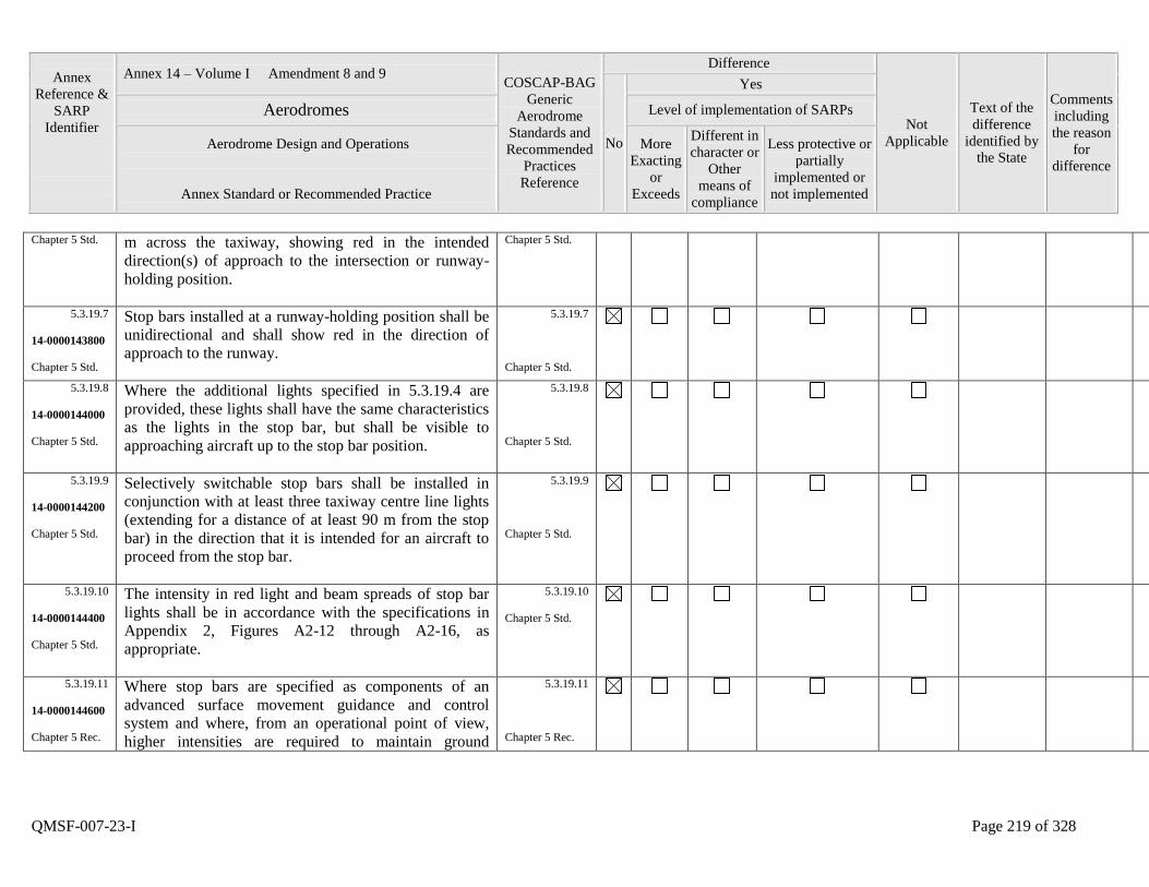
Annex
Reference &
SARP
Identifier
Annex 14 – Volume I Amendment 8 and 9 COSCAP-BAG
Generic
Aerodrome
Standards and
Recommended
Practices
Reference
Difference
Not
Applicable
Text of the
difference
identified by
the State
Comments
including
the reason
for
difference
No
Yes
Aerodromes Level of implementation of SARPs
Aerodrome Design and Operations
Annex Standard or Recommended Practice
More
Exacting
or
Exceeds
Different in
character or
Other
means of
compliance
Less protective or
partially
implemented or
not implemented
QMSF-007-23-I Page 219 of 328
Chapter 5 Std. m across the taxiway, showing red in the intended
direction(s) of approach to the intersection or runway-
holding position.
Chapter 5 Std.
5.3.19.7
14-0000143800
Chapter 5 Std.
Stop bars installed at a runway-holding position shall be
unidirectional and shall show red in the direction of
approach to the runway.
5.3.19.7
Chapter 5 Std.
5.3.19.8
14-0000144000
Chapter 5 Std.
Where the additional lights specified in 5.3.19.4 are
provided, these lights shall have the same characteristics
as the lights in the stop bar, but shall be visible to
approaching aircraft up to the stop bar position.
5.3.19.8
Chapter 5 Std.
5.3.19.9
14-0000144200
Chapter 5 Std.
Selectively switchable stop bars shall be installed in
conjunction with at least three taxiway centre line lights
(extending for a distance of at least 90 m from the stop
bar) in the direction that it is intended for an aircraft to
proceed from the stop bar.
5.3.19.9
Chapter 5 Std.
5.3.19.10
14-0000144400
Chapter 5 Std.
The intensity in red light and beam spreads of stop bar
lights shall be in accordance with the specifications in
Appendix 2, Figures A2-12 through A2-16, as
appropriate.
5.3.19.10
Chapter 5 Std.
5.3.19.11
14-0000144600
Chapter 5 Rec.
Where stop bars are specified as components of an
advanced surface movement guidance and control
system and where, from an operational point of view,
higher intensities are required to maintain ground
5.3.19.11
Chapter 5 Rec.
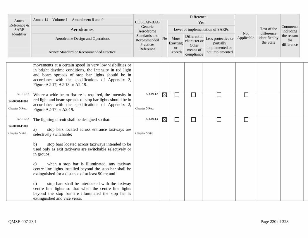
Annex
Reference &
SARP
Identifier
Annex 14 – Volume I Amendment 8 and 9 COSCAP-BAG
Generic
Aerodrome
Standards and
Recommended
Practices
Reference
Difference
Not
Applicable
Text of the
difference
identified by
the State
Comments
including
the reason
for
difference
No
Yes
Aerodromes Level of implementation of SARPs
Aerodrome Design and Operations
Annex Standard or Recommended Practice
More
Exacting
or
Exceeds
Different in
character or
Other
means of
compliance
Less protective or
partially
implemented or
not implemented
QMSF-007-23-I Page 220 of 328
movements at a certain speed in very low visibilities or
in bright daytime conditions, the intensity in red light
and beam spreads of stop bar lights should be in
accordance with the specifications of Appendix 2,
Figure A2-17, A2-18 or A2-19.
5.3.19.12
14-0000144800
Chapter 5 Rec.
Where a wide beam fixture is required, the intensity in
red light and beam spreads of stop bar lights should be in
accordance with the specifications of Appendix 2,
Figure A2-17 or A2-19.
5.3.19.12
Chapter 5 Rec.
5.3.19.13
14-0000145000
Chapter 5 Std.
The lighting circuit shall be designed so that:
a) stop bars located across entrance taxiways are
selectively switchable;
b) stop bars located across taxiways intended to be
used only as exit taxiways are switchable selectively or
in groups;
c) when a stop bar is illuminated, any taxiway
centre line lights installed beyond the stop bar shall be
extinguished for a distance of at least 90 m; and
d) stop bars shall be interlocked with the taxiway
centre line lights so that when the centre line lights
beyond the stop bar are illuminated the stop bar is
extinguished and vice versa.
5.3.19.13
Chapter 5 Std.
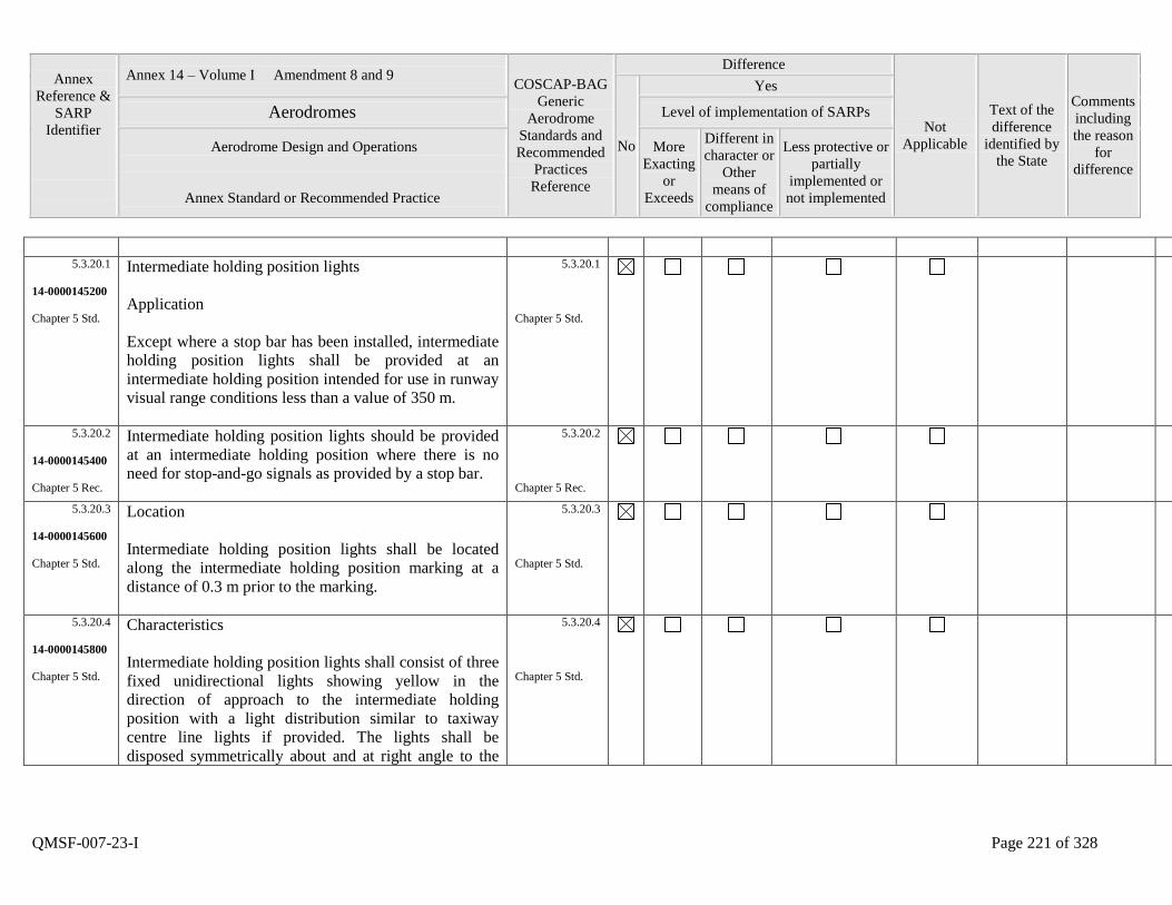
Annex
Reference &
SARP
Identifier
Annex 14 – Volume I Amendment 8 and 9 COSCAP-BAG
Generic
Aerodrome
Standards and
Recommended
Practices
Reference
Difference
Not
Applicable
Text of the
difference
identified by
the State
Comments
including
the reason
for
difference
No
Yes
Aerodromes Level of implementation of SARPs
Aerodrome Design and Operations
Annex Standard or Recommended Practice
More
Exacting
or
Exceeds
Different in
character or
Other
means of
compliance
Less protective or
partially
implemented or
not implemented
QMSF-007-23-I Page 221 of 328
5.3.20.1
14-0000145200
Chapter 5 Std.
Intermediate holding position lights
Application
Except where a stop bar has been installed, intermediate
holding position lights shall be provided at an
intermediate holding position intended for use in runway
visual range conditions less than a value of 350 m.
5.3.20.1
Chapter 5 Std.
5.3.20.2
14-0000145400
Chapter 5 Rec.
Intermediate holding position lights should be provided
at an intermediate holding position where there is no
need for stop-and-go signals as provided by a stop bar.
5.3.20.2
Chapter 5 Rec.
5.3.20.3
14-0000145600
Chapter 5 Std.
Location
Intermediate holding position lights shall be located
along the intermediate holding position marking at a
distance of 0.3 m prior to the marking.
5.3.20.3
Chapter 5 Std.
5.3.20.4
14-0000145800
Chapter 5 Std.
Characteristics
Intermediate holding position lights shall consist of three
fixed unidirectional lights showing yellow in the
direction of approach to the intermediate holding
position with a light distribution similar to taxiway
centre line lights if provided. The lights shall be
disposed symmetrically about and at right angle to the
5.3.20.4
Chapter 5 Std.
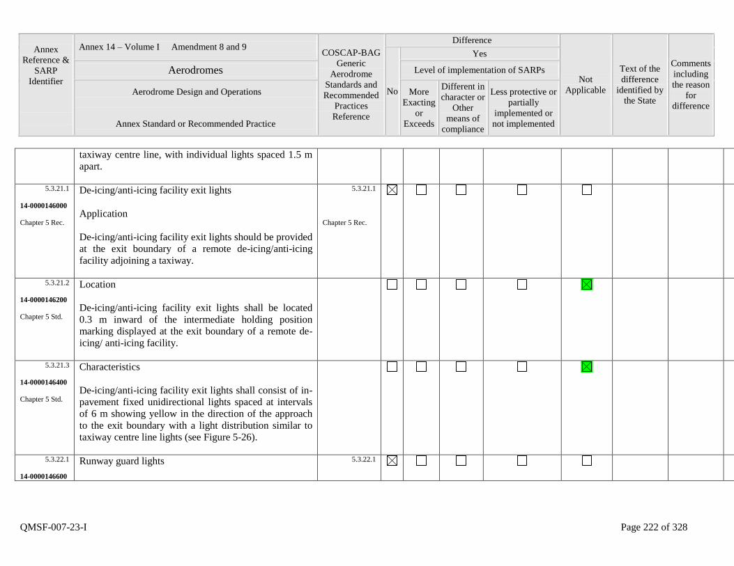
Annex
Reference &
SARP
Identifier
Annex 14 – Volume I Amendment 8 and 9 COSCAP-BAG
Generic
Aerodrome
Standards and
Recommended
Practices
Reference
Difference
Not
Applicable
Text of the
difference
identified by
the State
Comments
including
the reason
for
difference
No
Yes
Aerodromes Level of implementation of SARPs
Aerodrome Design and Operations
Annex Standard or Recommended Practice
More
Exacting
or
Exceeds
Different in
character or
Other
means of
compliance
Less protective or
partially
implemented or
not implemented
QMSF-007-23-I Page 222 of 328
taxiway centre line, with individual lights spaced 1.5 m
apart.
5.3.21.1
14-0000146000
Chapter 5 Rec.
De-icing/anti-icing facility exit lights
Application
De-icing/anti-icing facility exit lights should be provided
at the exit boundary of a remote de-icing/anti-icing
facility adjoining a taxiway.
5.3.21.1
Chapter 5 Rec.
5.3.21.2
14-0000146200
Chapter 5 Std.
Location
De-icing/anti-icing facility exit lights shall be located
0.3 m inward of the intermediate holding position
marking displayed at the exit boundary of a remote de-
icing/ anti-icing facility.
5.3.21.3
14-0000146400
Chapter 5 Std.
Characteristics
De-icing/anti-icing facility exit lights shall consist of in-
pavement fixed unidirectional lights spaced at intervals
of 6 m showing yellow in the direction of the approach
to the exit boundary with a light distribution similar to
taxiway centre line lights (see Figure 5-26).
5.3.22.1
14-0000146600
Runway guard lights
5.3.22.1
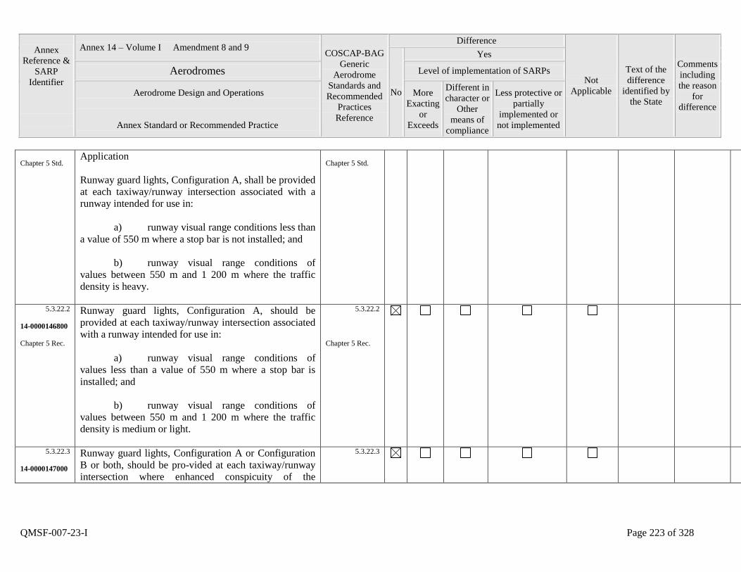
Annex
Reference &
SARP
Identifier
Annex 14 – Volume I Amendment 8 and 9 COSCAP-BAG
Generic
Aerodrome
Standards and
Recommended
Practices
Reference
Difference
Not
Applicable
Text of the
difference
identified by
the State
Comments
including
the reason
for
difference
No
Yes
Aerodromes Level of implementation of SARPs
Aerodrome Design and Operations
Annex Standard or Recommended Practice
More
Exacting
or
Exceeds
Different in
character or
Other
means of
compliance
Less protective or
partially
implemented or
not implemented
QMSF-007-23-I Page 223 of 328
Chapter 5 Std. Application
Runway guard lights, Configuration A, shall be provided
at each taxiway/runway intersection associated with a
runway intended for use in:
a) runway visual range conditions less than
a value of 550 m where a stop bar is not installed; and
b) runway visual range conditions of
values between 550 m and 1 200 m where the traffic
density is heavy.
Chapter 5 Std.
5.3.22.2
14-0000146800
Chapter 5 Rec.
Runway guard lights, Configuration A, should be
provided at each taxiway/runway intersection associated
with a runway intended for use in:
a) runway visual range conditions of
values less than a value of 550 m where a stop bar is
installed; and
b) runway visual range conditions of
values between 550 m and 1 200 m where the traffic
density is medium or light.
5.3.22.2
Chapter 5 Rec.
5.3.22.3
14-0000147000
Runway guard lights, Configuration A or Configuration
B or both, should be pro-vided at each taxiway/runway
intersection where enhanced conspicuity of the
5.3.22.3
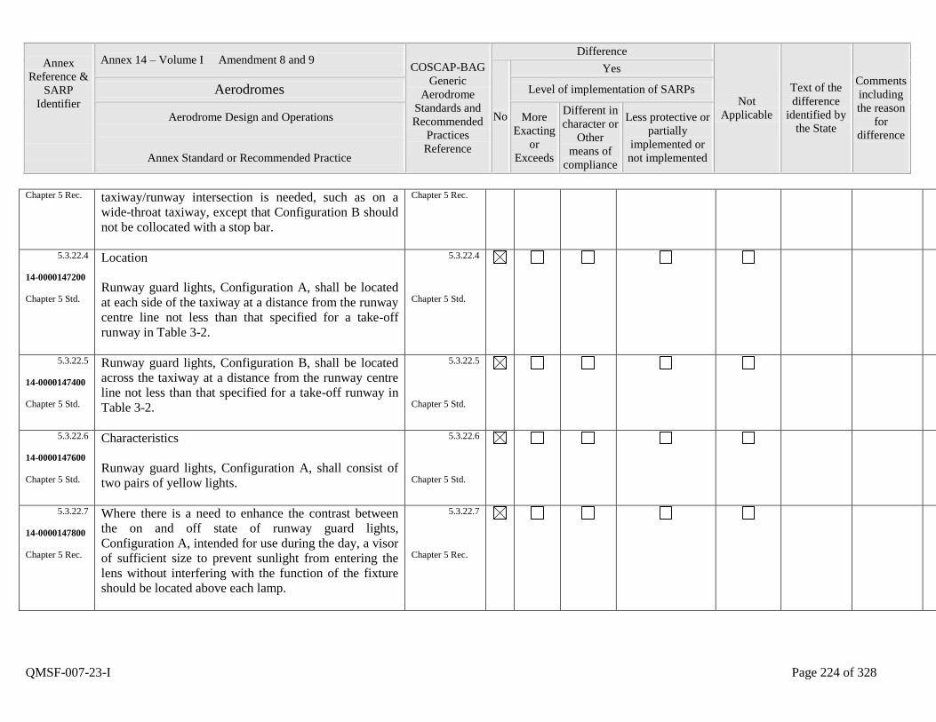
Annex
Reference &
SARP
Identifier
Annex 14 – Volume I Amendment 8 and 9 COSCAP-BAG
Generic
Aerodrome
Standards and
Recommended
Practices
Reference
Difference
Not
Applicable
Text of the
difference
identified by
the State
Comments
including
the reason
for
difference
No
Yes
Aerodromes Level of implementation of SARPs
Aerodrome Design and Operations
Annex Standard or Recommended Practice
More
Exacting
or
Exceeds
Different in
character or
Other
means of
compliance
Less protective or
partially
implemented or
not implemented
QMSF-007-23-I Page 224 of 328
Chapter 5 Rec. taxiway/runway intersection is needed, such as on a
wide-throat taxiway, except that Configuration B should
not be collocated with a stop bar.
Chapter 5 Rec.
5.3.22.4
14-0000147200
Chapter 5 Std.
Location
Runway guard lights, Configuration A, shall be located
at each side of the taxiway at a distance from the runway
centre line not less than that specified for a take-off
runway in Table 3-2.
5.3.22.4
Chapter 5 Std.
5.3.22.5
14-0000147400
Chapter 5 Std.
Runway guard lights, Configuration B, shall be located
across the taxiway at a distance from the runway centre
line not less than that specified for a take-off runway in
Table 3-2.
5.3.22.5
Chapter 5 Std.
5.3.22.6
14-0000147600
Chapter 5 Std.
Characteristics
Runway guard lights, Configuration A, shall consist of
two pairs of yellow lights.
5.3.22.6
Chapter 5 Std.
5.3.22.7
14-0000147800
Chapter 5 Rec.
Where there is a need to enhance the contrast between
the on and off state of runway guard lights,
Configuration A, intended for use during the day, a visor
of sufficient size to prevent sunlight from entering the
lens without interfering with the function of the fixture
should be located above each lamp.
5.3.22.7
Chapter 5 Rec.
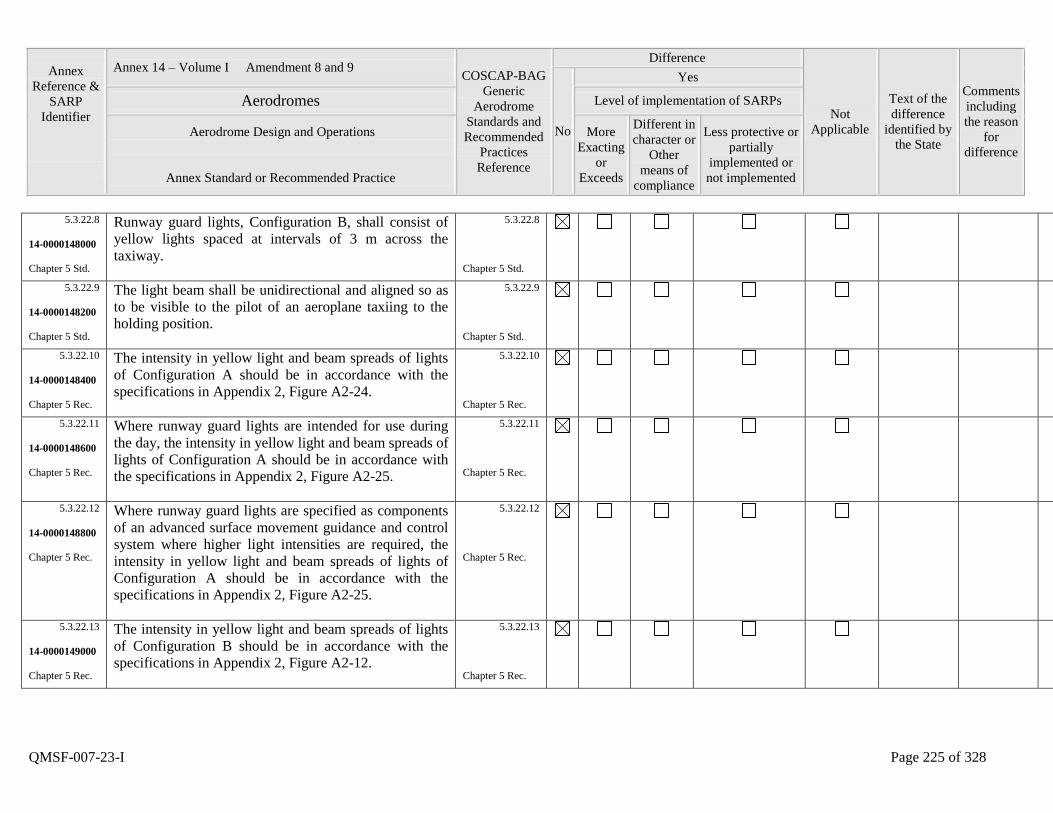
Annex
Reference &
SARP
Identifier
Annex 14 – Volume I Amendment 8 and 9 COSCAP-BAG
Generic
Aerodrome
Standards and
Recommended
Practices
Reference
Difference
Not
Applicable
Text of the
difference
identified by
the State
Comments
including
the reason
for
difference
No
Yes
Aerodromes Level of implementation of SARPs
Aerodrome Design and Operations
Annex Standard or Recommended Practice
More
Exacting
or
Exceeds
Different in
character or
Other
means of
compliance
Less protective or
partially
implemented or
not implemented
QMSF-007-23-I Page 225 of 328
5.3.22.8
14-0000148000
Chapter 5 Std.
Runway guard lights, Configuration B, shall consist of
yellow lights spaced at intervals of 3 m across the
taxiway.
5.3.22.8
Chapter 5 Std.
5.3.22.9
14-0000148200
Chapter 5 Std.
The light beam shall be unidirectional and aligned so as
to be visible to the pilot of an aeroplane taxiing to the
holding position.
5.3.22.9
Chapter 5 Std.
5.3.22.10
14-0000148400
Chapter 5 Rec.
The intensity in yellow light and beam spreads of lights
of Configuration A should be in accordance with the
specifications in Appendix 2, Figure A2-24.
5.3.22.10
Chapter 5 Rec.
5.3.22.11
14-0000148600
Chapter 5 Rec.
Where runway guard lights are intended for use during
the day, the intensity in yellow light and beam spreads of
lights of Configuration A should be in accordance with
the specifications in Appendix 2, Figure A2-25.
5.3.22.11
Chapter 5 Rec.
5.3.22.12
14-0000148800
Chapter 5 Rec.
Where runway guard lights are specified as components
of an advanced surface movement guidance and control
system where higher light intensities are required, the
intensity in yellow light and beam spreads of lights of
Configuration A should be in accordance with the
specifications in Appendix 2, Figure A2-25.
5.3.22.12
Chapter 5 Rec.
5.3.22.13
14-0000149000
Chapter 5 Rec.
The intensity in yellow light and beam spreads of lights
of Configuration B should be in accordance with the
specifications in Appendix 2, Figure A2-12.
5.3.22.13
Chapter 5 Rec.
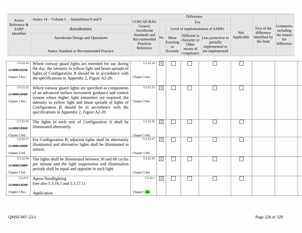
Annex
Reference &
SARP
Identifier
Annex 14 – Volume I Amendment 8 and 9 COSCAP-BAG
Generic
Aerodrome
Standards and
Recommended
Practices
Reference
Difference
Not
Applicable
Text of the
difference
identified by
the State
Comments
including
the reason
for
difference
No
Yes
Aerodromes Level of implementation of SARPs
Aerodrome Design and Operations
Annex Standard or Recommended Practice
More
Exacting
or
Exceeds
Different in
character or
Other
means of
compliance
Less protective or
partially
implemented or
not implemented
QMSF-007-23-I Page 226 of 328
5.3.22.14
14-0000149200
Chapter 5 Rec.
Where runway guard lights are intended for use during
the day, the intensity in yellow light and beam spreads of
lights of Configuration B should be in accordance with
the specifications in Appendix 2, Figure A2-20.
5.3.22.14
Chapter 5 Rec.
5.3.22.15
14-0000149400
Chapter 5 Rec.
Where runway guard lights are specified as components
of an advanced surface movement guidance and control
system where higher light intensities are required, the
intensity in yellow light and beam spreads of lights of
Configuration B should be in accordance with the
specifications in Appendix 2, Figure A2-20.
5.3.22.15
Chapter 5 Rec.
5.3.22.16
14-0000149600
Chapter 5 Std.
The lights in each unit of Configuration A shall be
illuminated alternately.
5.3.22.16
Chapter 5 Std.
5.3.22.17
14-0000149800
Chapter 5 Std.
For Configuration B, adjacent lights shall be alternately
illuminated and alternative lights shall be illuminated in
unison.
5.3.22.17
Chapter 5 Std.
5.3.22.18
14-0000150000
Chapter 5 Std.
The lights shall be illuminated between 30 and 60 cycles
per minute and the light suppression and illumination
periods shall be equal and opposite in each light.
5.3.22.18
Chapter 5 Std.
5.3.23.1
14-0000150200
Chapter 5 Rec.
Apron floodlighting
(see also 5.3.16.1 and 5.3.17.1)
Application
5.3.23.1
Chapter 5 Std.

Annex
Reference &
SARP
Identifier
Annex 14 – Volume I Amendment 8 and 9 COSCAP-BAG
Generic
Aerodrome
Standards and
Recommended
Practices
Reference
Difference
Not
Applicable
Text of the
difference
identified by
the State
Comments
including
the reason
for
difference
No
Yes
Aerodromes Level of implementation of SARPs
Aerodrome Design and Operations
Annex Standard or Recommended Practice
More
Exacting
or
Exceeds
Different in
character or
Other
means of
compliance
Less protective or
partially
implemented or
not implemented
QMSF-007-23-I Page 227 of 328
Apron floodlighting should be provided on an apron, on
a de-icing/anti-icing facility and on a designated isolated
aircraft parking position intended to be used at night.
5.3.23.2
14-0000150400
Chapter 5 Rec.
Location
Apron floodlights should be located so as to provide
adequate illumination on all apron service areas, with a
minimum of glare to pilots of aircraft in flight and on the
ground, aerodrome and apron controllers, and personnel
on the apron. The arrangement and aiming of floodlights
should be such that an aircraft stand receives light from
two or more directions to minimize shadows.
5.3.23.2
Chapter 5 Rec.
5.3.23.3
14-0000150600
Chapter 5 Std.
Characteristics
The spectral distribution of apron floodlights shall be
such that the colours used for aircraft marking connected
with routine servicing, and for surface and obstacle
marking, can be correctly identified.
5.3.23.3
Chapter 5 Std.
5.3.23.4
14-0000150800
Chapter 5 Rec.
The average illuminance should be at least the
following:
Aircraft stand:
- horizontal illuminance - 20 lux with a
5.3.23.4
Chapter 5 Rec.
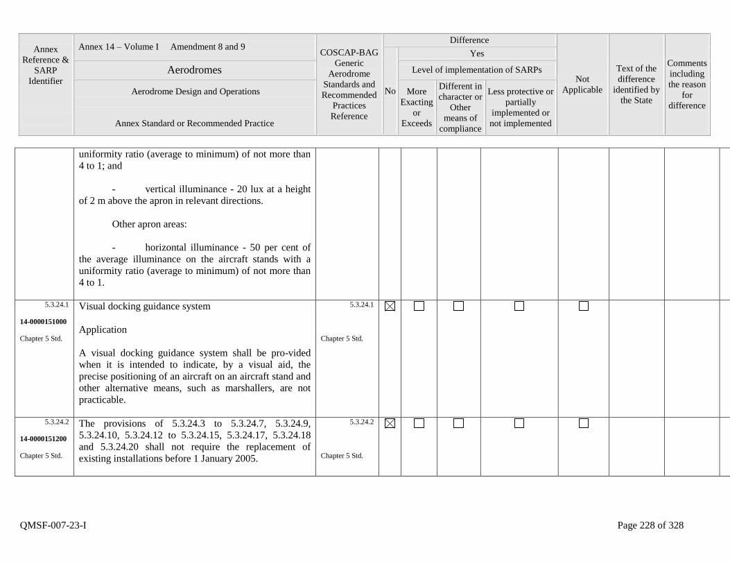
Annex
Reference &
SARP
Identifier
Annex 14 – Volume I Amendment 8 and 9 COSCAP-BAG
Generic
Aerodrome
Standards and
Recommended
Practices
Reference
Difference
Not
Applicable
Text of the
difference
identified by
the State
Comments
including
the reason
for
difference
No
Yes
Aerodromes Level of implementation of SARPs
Aerodrome Design and Operations
Annex Standard or Recommended Practice
More
Exacting
or
Exceeds
Different in
character or
Other
means of
compliance
Less protective or
partially
implemented or
not implemented
QMSF-007-23-I Page 228 of 328
uniformity ratio (average to minimum) of not more than
4 to 1; and
- vertical illuminance - 20 lux at a height
of 2 m above the apron in relevant directions.
Other apron areas:
- horizontal illuminance - 50 per cent of
the average illuminance on the aircraft stands with a
uniformity ratio (average to minimum) of not more than
4 to 1.
5.3.24.1
14-0000151000
Chapter 5 Std.
Visual docking guidance system
Application
A visual docking guidance system shall be pro-vided
when it is intended to indicate, by a visual aid, the
precise positioning of an aircraft on an aircraft stand and
other alternative means, such as marshallers, are not
practicable.
5.3.24.1
Chapter 5 Std.
5.3.24.2
14-0000151200
Chapter 5 Std.
The provisions of 5.3.24.3 to 5.3.24.7, 5.3.24.9,
5.3.24.10, 5.3.24.12 to 5.3.24.15, 5.3.24.17, 5.3.24.18
and 5.3.24.20 shall not require the replacement of
existing installations before 1 January 2005.
5.3.24.2
Chapter 5 Std.
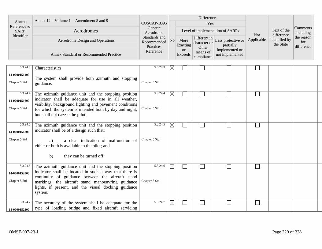
Annex
Reference &
SARP
Identifier
Annex 14 – Volume I Amendment 8 and 9 COSCAP-BAG
Generic
Aerodrome
Standards and
Recommended
Practices
Reference
Difference
Not
Applicable
Text of the
difference
identified by
the State
Comments
including
the reason
for
difference
No
Yes
Aerodromes Level of implementation of SARPs
Aerodrome Design and Operations
Annex Standard or Recommended Practice
More
Exacting
or
Exceeds
Different in
character or
Other
means of
compliance
Less protective or
partially
implemented or
not implemented
QMSF-007-23-I Page 229 of 328
5.3.24.3
14-0000151400
Chapter 5 Std.
Characteristics
The system shall provide both azimuth and stopping
guidance.
5.3.24.3
Chapter 5 Std.
5.3.24.4
14-0000151600
Chapter 5 Std.
The azimuth guidance unit and the stopping position
indicator shall be adequate for use in all weather,
visibility, background lighting and pavement conditions
for which the system is intended both by day and night,
but shall not dazzle the pilot.
5.3.24.4
Chapter 5 Std.
5.3.24.5
14-0000151800
Chapter 5 Std.
The azimuth guidance unit and the stopping position
indicator shall be of a design such that:
a) a clear indication of malfunction of
either or both is available to the pilot; and
b) they can be turned off.
5.3.24.5
Chapter 5 Std.
5.3.24.6
14-0000152000
Chapter 5 Std.
The azimuth guidance unit and the stopping position
indicator shall be located in such a way that there is
continuity of guidance between the aircraft stand
markings, the aircraft stand manoeuvring guidance
lights, if present, and the visual docking guidance
system.
5.3.24.6
Chapter 5 Std.
5.3.24.7
14-0000152200
The accuracy of the system shall be adequate for the
type of loading bridge and fixed aircraft servicing
5.3.24.7
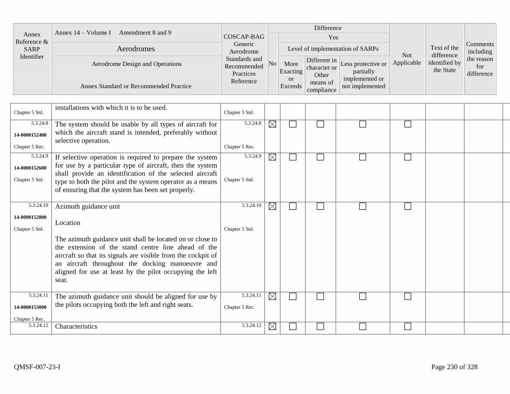
Annex
Reference &
SARP
Identifier
Annex 14 – Volume I Amendment 8 and 9 COSCAP-BAG
Generic
Aerodrome
Standards and
Recommended
Practices
Reference
Difference
Not
Applicable
Text of the
difference
identified by
the State
Comments
including
the reason
for
difference
No
Yes
Aerodromes Level of implementation of SARPs
Aerodrome Design and Operations
Annex Standard or Recommended Practice
More
Exacting
or
Exceeds
Different in
character or
Other
means of
compliance
Less protective or
partially
implemented or
not implemented
QMSF-007-23-I Page 230 of 328
Chapter 5 Std. installations with which it is to be used.
Chapter 5 Std.
5.3.24.8
14-0000152400
Chapter 5 Rec.
The system should be usable by all types of aircraft for
which the aircraft stand is intended, preferably without
selective operation.
5.3.24.8
Chapter 5 Rec.
5.3.24.9
14-0000152600
Chapter 5 Std.
If selective operation is required to prepare the system
for use by a particular type of aircraft, then the system
shall provide an identification of the selected aircraft
type to both the pilot and the system operator as a means
of ensuring that the system has been set properly.
5.3.24.9
Chapter 5 Std.
5.3.24.10
14-0000152800
Chapter 5 Std.
Azimuth guidance unit
Location
The azimuth guidance unit shall be located on or close to
the extension of the stand centre line ahead of the
aircraft so that its signals are visible from the cockpit of
an aircraft throughout the docking manoeuvre and
aligned for use at least by the pilot occupying the left
seat.
5.3.24.10
Chapter 5 Std.
5.3.24.11
14-0000153000
Chapter 5 Rec.
The azimuth guidance unit should be aligned for use by
the pilots occupying both the left and right seats.
5.3.24.11
Chapter 5 Rec.
5.3.24.12
Characteristics 5.3.24.12
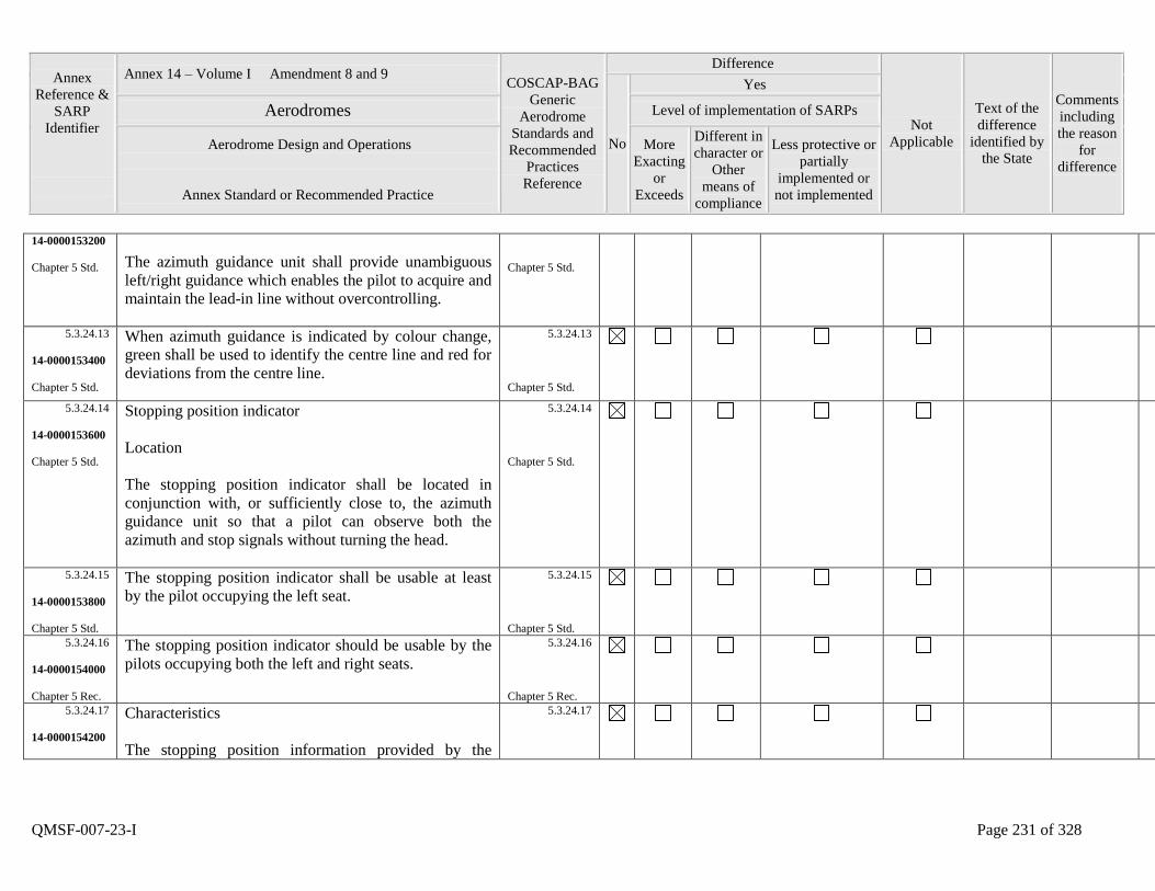
Annex
Reference &
SARP
Identifier
Annex 14 – Volume I Amendment 8 and 9 COSCAP-BAG
Generic
Aerodrome
Standards and
Recommended
Practices
Reference
Difference
Not
Applicable
Text of the
difference
identified by
the State
Comments
including
the reason
for
difference
No
Yes
Aerodromes Level of implementation of SARPs
Aerodrome Design and Operations
Annex Standard or Recommended Practice
More
Exacting
or
Exceeds
Different in
character or
Other
means of
compliance
Less protective or
partially
implemented or
not implemented
QMSF-007-23-I Page 231 of 328
14-0000153200
Chapter 5 Std.
The azimuth guidance unit shall provide unambiguous
left/right guidance which enables the pilot to acquire and
maintain the lead-in line without overcontrolling.
Chapter 5 Std.
5.3.24.13
14-0000153400
Chapter 5 Std.
When azimuth guidance is indicated by colour change,
green shall be used to identify the centre line and red for
deviations from the centre line.
5.3.24.13
Chapter 5 Std.
5.3.24.14
14-0000153600
Chapter 5 Std.
Stopping position indicator
Location
The stopping position indicator shall be located in
conjunction with, or sufficiently close to, the azimuth
guidance unit so that a pilot can observe both the
azimuth and stop signals without turning the head.
5.3.24.14
Chapter 5 Std.
5.3.24.15
14-0000153800
Chapter 5 Std.
The stopping position indicator shall be usable at least
by the pilot occupying the left seat.
5.3.24.15
Chapter 5 Std.
5.3.24.16
14-0000154000
Chapter 5 Rec.
The stopping position indicator should be usable by the
pilots occupying both the left and right seats.
5.3.24.16
Chapter 5 Rec.
5.3.24.17
14-0000154200
Characteristics
The stopping position information provided by the
5.3.24.17
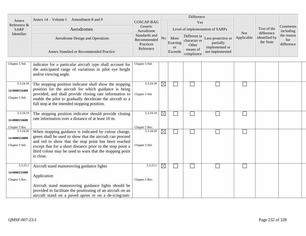
Annex
Reference &
SARP
Identifier
Annex 14 – Volume I Amendment 8 and 9 COSCAP-BAG
Generic
Aerodrome
Standards and
Recommended
Practices
Reference
Difference
Not
Applicable
Text of the
difference
identified by
the State
Comments
including
the reason
for
difference
No
Yes
Aerodromes Level of implementation of SARPs
Aerodrome Design and Operations
Annex Standard or Recommended Practice
More
Exacting
or
Exceeds
Different in
character or
Other
means of
compliance
Less protective or
partially
implemented or
not implemented
QMSF-007-23-I Page 232 of 328
Chapter 5 Std. indicator for a particular aircraft type shall account for
the anticipated range of variations in pilot eye height
and/or viewing angle.
Chapter 5 Std.
5.3.24.18
14-0000154400
Chapter 5 Std.
The stopping position indicator shall show the stopping
position for the aircraft for which guidance is being
provided, and shall provide closing rate information to
enable the pilot to gradually decelerate the aircraft to a
full stop at the intended stopping position.
5.3.24.18
Chapter 5 Std.
5.3.24.19
14-0000154600
Chapter 5 Rec.
The stopping position indicator should provide closing
rate information over a distance of at least 10 m.
5.3.24.19
Chapter 5 Rec.
5.3.24.20
14-0000154800
Chapter 5 Std.
When stopping guidance is indicated by colour change,
green shall be used to show that the aircraft can proceed
and red to show that the stop point has been reached
except that for a short distance prior to the stop point a
third colour may be used to warn that the stopping point
is close.
5.3.24.20
Chapter 5 Std.
5.3.25.1
14-0000155000
Chapter 5 Rec.
Aircraft stand manoeuvring guidance lights
Application
Aircraft stand manoeuvring guidance lights should be
provided to facilitate the positioning of an aircraft on an
aircraft stand on a paved apron or on a de-icing/anti-
5.3.25.1
Chapter 5 Rec.
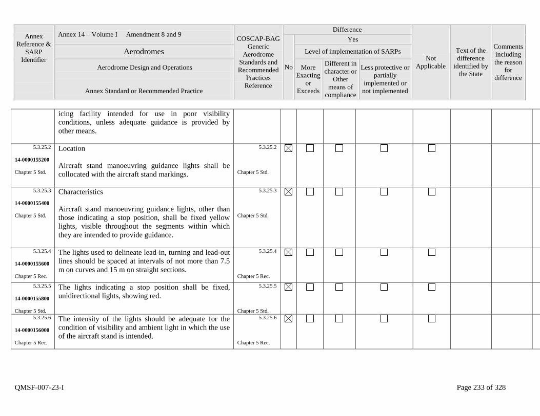
Annex
Reference &
SARP
Identifier
Annex 14 – Volume I Amendment 8 and 9 COSCAP-BAG
Generic
Aerodrome
Standards and
Recommended
Practices
Reference
Difference
Not
Applicable
Text of the
difference
identified by
the State
Comments
including
the reason
for
difference
No
Yes
Aerodromes Level of implementation of SARPs
Aerodrome Design and Operations
Annex Standard or Recommended Practice
More
Exacting
or
Exceeds
Different in
character or
Other
means of
compliance
Less protective or
partially
implemented or
not implemented
QMSF-007-23-I Page 233 of 328
icing facility intended for use in poor visibility
conditions, unless adequate guidance is provided by
other means.
5.3.25.2
14-0000155200
Chapter 5 Std.
Location
Aircraft stand manoeuvring guidance lights shall be
collocated with the aircraft stand markings.
5.3.25.2
Chapter 5 Std.
5.3.25.3
14-0000155400
Chapter 5 Std.
Characteristics
Aircraft stand manoeuvring guidance lights, other than
those indicating a stop position, shall be fixed yellow
lights, visible throughout the segments within which
they are intended to provide guidance.
5.3.25.3
Chapter 5 Std.
5.3.25.4
14-0000155600
Chapter 5 Rec.
The lights used to delineate lead-in, turning and lead-out
lines should be spaced at intervals of not more than 7.5
m on curves and 15 m on straight sections.
5.3.25.4
Chapter 5 Rec.
5.3.25.5
14-0000155800
Chapter 5 Std.
The lights indicating a stop position shall be fixed,
unidirectional lights, showing red.
5.3.25.5
Chapter 5 Std.
5.3.25.6
14-0000156000
Chapter 5 Rec.
The intensity of the lights should be adequate for the
condition of visibility and ambient light in which the use
of the aircraft stand is intended.
5.3.25.6
Chapter 5 Rec.
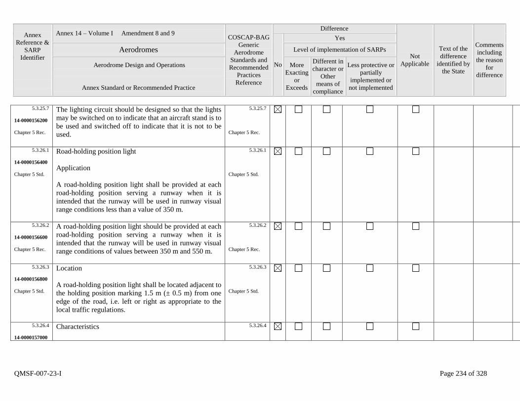
Annex
Reference &
SARP
Identifier
Annex 14 – Volume I Amendment 8 and 9 COSCAP-BAG
Generic
Aerodrome
Standards and
Recommended
Practices
Reference
Difference
Not
Applicable
Text of the
difference
identified by
the State
Comments
including
the reason
for
difference
No
Yes
Aerodromes Level of implementation of SARPs
Aerodrome Design and Operations
Annex Standard or Recommended Practice
More
Exacting
or
Exceeds
Different in
character or
Other
means of
compliance
Less protective or
partially
implemented or
not implemented
QMSF-007-23-I Page 234 of 328
5.3.25.7
14-0000156200
Chapter 5 Rec.
The lighting circuit should be designed so that the lights
may be switched on to indicate that an aircraft stand is to
be used and switched off to indicate that it is not to be
used.
5.3.25.7
Chapter 5 Rec.
5.3.26.1
14-0000156400
Chapter 5 Std.
Road-holding position light
Application
A road-holding position light shall be provided at each
road-holding position serving a runway when it is
intended that the runway will be used in runway visual
range conditions less than a value of 350 m.
5.3.26.1
Chapter 5 Std.
5.3.26.2
14-0000156600
Chapter 5 Rec.
A road-holding position light should be provided at each
road-holding position serving a runway when it is
intended that the runway will be used in runway visual
range conditions of values between 350 m and 550 m.
5.3.26.2
Chapter 5 Rec.
5.3.26.3
14-0000156800
Chapter 5 Std.
Location
A road-holding position light shall be located adjacent to
the holding position marking 1.5 m (± 0.5 m) from one
edge of the road, i.e. left or right as appropriate to the
local traffic regulations.
5.3.26.3
Chapter 5 Std.
5.3.26.4
14-0000157000
Characteristics
5.3.26.4
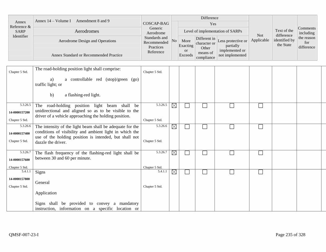
Annex
Reference &
SARP
Identifier
Annex 14 – Volume I Amendment 8 and 9 COSCAP-BAG
Generic
Aerodrome
Standards and
Recommended
Practices
Reference
Difference
Not
Applicable
Text of the
difference
identified by
the State
Comments
including
the reason
for
difference
No
Yes
Aerodromes Level of implementation of SARPs
Aerodrome Design and Operations
Annex Standard or Recommended Practice
More
Exacting
or
Exceeds
Different in
character or
Other
means of
compliance
Less protective or
partially
implemented or
not implemented
QMSF-007-23-I Page 235 of 328
Chapter 5 Std. The road-holding position light shall comprise:
a) a controllable red (stop)/green (go)
traffic light; or
b) a flashing-red light.
Chapter 5 Std.
5.3.26.5
14-0000157200
Chapter 5 Std.
The road-holding position light beam shall be
unidirectional and aligned so as to be visible to the
driver of a vehicle approaching the holding position.
5.3.26.5
Chapter 5 Std.
5.3.26.6
14-0000157400
Chapter 5 Std.
The intensity of the light beam shall be adequate for the
conditions of visibility and ambient light in which the
use of the holding position is intended, but shall not
dazzle the driver.
5.3.26.6
Chapter 5 Std.
5.3.26.7
14-0000157600
Chapter 5 Std.
The flash frequency of the flashing-red light shall be
between 30 and 60 per minute.
5.3.26.7
Chapter 5 Std.
5.4.1.1
14-0000157800
Chapter 5 Std.
Signs
General
Application
Signs shall be provided to convey a mandatory
instruction, information on a specific location or
5.4.1.1
Chapter 5 Std.
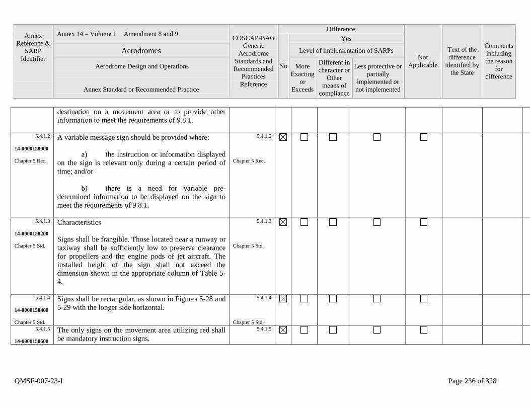
Annex
Reference &
SARP
Identifier
Annex 14 – Volume I Amendment 8 and 9 COSCAP-BAG
Generic
Aerodrome
Standards and
Recommended
Practices
Reference
Difference
Not
Applicable
Text of the
difference
identified by
the State
Comments
including
the reason
for
difference
No
Yes
Aerodromes Level of implementation of SARPs
Aerodrome Design and Operations
Annex Standard or Recommended Practice
More
Exacting
or
Exceeds
Different in
character or
Other
means of
compliance
Less protective or
partially
implemented or
not implemented
QMSF-007-23-I Page 236 of 328
destination on a movement area or to provide other
information to meet the requirements of 9.8.1.
5.4.1.2
14-0000158000
Chapter 5 Rec.
A variable message sign should be provided where:
a) the instruction or information displayed
on the sign is relevant only during a certain period of
time; and/or
b) there is a need for variable pre-
determined information to be displayed on the sign to
meet the requirements of 9.8.1.
5.4.1.2
Chapter 5 Rec.
5.4.1.3
14-0000158200
Chapter 5 Std.
Characteristics
Signs shall be frangible. Those located near a runway or
taxiway shall be sufficiently low to preserve clearance
for propellers and the engine pods of jet aircraft. The
installed height of the sign shall not exceed the
dimension shown in the appropriate column of Table 5-
4.
5.4.1.3
Chapter 5 Std.
5.4.1.4
14-0000158400
Chapter 5 Std.
Signs shall be rectangular, as shown in Figures 5-28 and
5-29 with the longer side horizontal.
5.4.1.4
Chapter 5 Std.
5.4.1.5
14-0000158600
The only signs on the movement area utilizing red shall
be mandatory instruction signs.
5.4.1.5

Annex
Reference &
SARP
Identifier
Annex 14 – Volume I Amendment 8 and 9 COSCAP-BAG
Generic
Aerodrome
Standards and
Recommended
Practices
Reference
Difference
Not
Applicable
Text of the
difference
identified by
the State
Comments
including
the reason
for
difference
No
Yes
Aerodromes Level of implementation of SARPs
Aerodrome Design and Operations
Annex Standard or Recommended Practice
More
Exacting
or
Exceeds
Different in
character or
Other
means of
compliance
Less protective or
partially
implemented or
not implemented
QMSF-007-23-I Page 237 of 328
Chapter 5 Std. Chapter 5 Std.
5.4.1.6
14-0000158800
Chapter 5 Std.
The inscriptions on a sign shall be in accordance with
the provisions of Appendix 4.
5.4.1.6
Chapter 5 Std.
5.4.1.7
14-0000159000
Chapter 5 Std.
Signs shall be illuminated in accordance with the
provisions of Appendix 4 when intended for use:
a) in runway visual range conditions less
than a value of 800 m; or
b) at night in association with instrument
runways; or
c) at night in association with non-
instrument runways where the code number is 3 or 4.
5.4.1.7
Chapter 5 Std.
5.4.1.8
14-0000159200
Chapter 5 Std.
Signs shall be retroreflective and/or illuminated in
accordance with the provisions of Appendix 4 when
intended for use at night in association with non-
instrument runways where the code number is 1 or 2.
5.4.1.8
Chapter 5 Std.
5.4.1.9
14-0000159400
Chapter 5 Std.
A variable message sign shall show a blank face when
not in use.
5.4.1.9
Chapter 5 Std.
5.4.1.10
14-0000159600
In case of failure, a variable message sign shall not
provide information that could lead to unsafe action
5.4.1.10
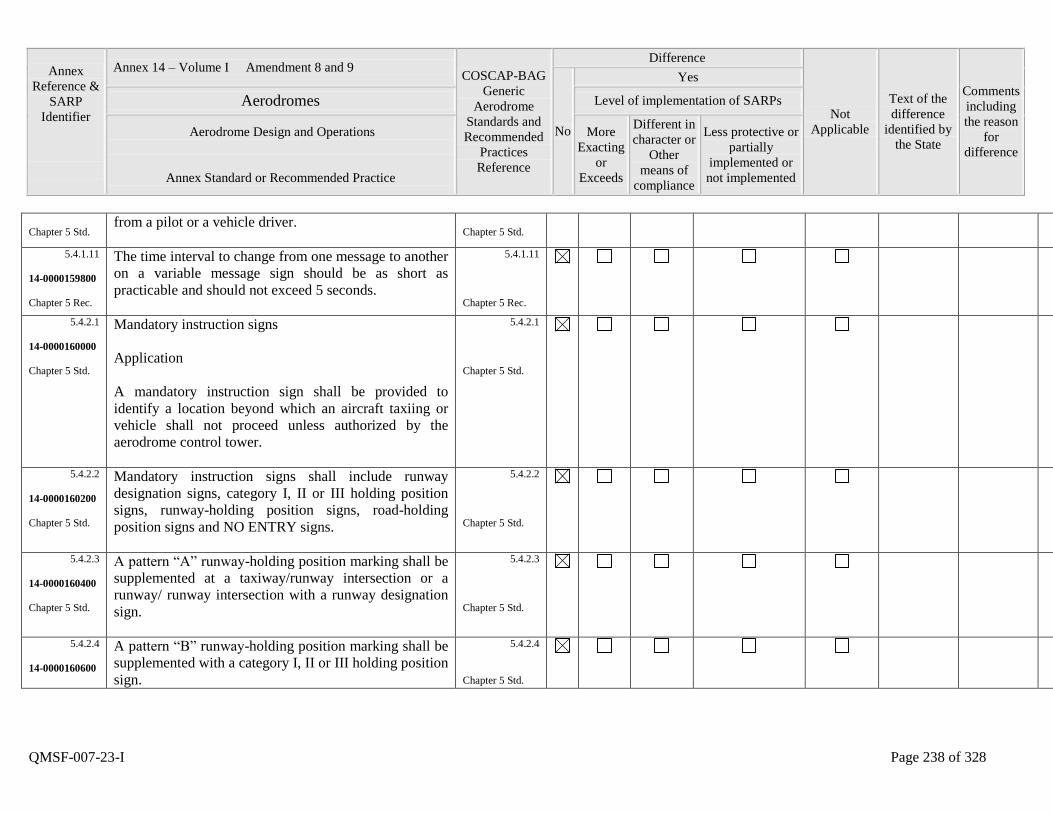
Annex
Reference &
SARP
Identifier
Annex 14 – Volume I Amendment 8 and 9 COSCAP-BAG
Generic
Aerodrome
Standards and
Recommended
Practices
Reference
Difference
Not
Applicable
Text of the
difference
identified by
the State
Comments
including
the reason
for
difference
No
Yes
Aerodromes Level of implementation of SARPs
Aerodrome Design and Operations
Annex Standard or Recommended Practice
More
Exacting
or
Exceeds
Different in
character or
Other
means of
compliance
Less protective or
partially
implemented or
not implemented
QMSF-007-23-I Page 238 of 328
Chapter 5 Std. from a pilot or a vehicle driver.
Chapter 5 Std.
5.4.1.11
14-0000159800
Chapter 5 Rec.
The time interval to change from one message to another
on a variable message sign should be as short as
practicable and should not exceed 5 seconds.
5.4.1.11
Chapter 5 Rec.
5.4.2.1
14-0000160000
Chapter 5 Std.
Mandatory instruction signs
Application
A mandatory instruction sign shall be provided to
identify a location beyond which an aircraft taxiing or
vehicle shall not proceed unless authorized by the
aerodrome control tower.
5.4.2.1
Chapter 5 Std.
5.4.2.2
14-0000160200
Chapter 5 Std.
Mandatory instruction signs shall include runway
designation signs, category I, II or III holding position
signs, runway-holding position signs, road-holding
position signs and NO ENTRY signs.
5.4.2.2
Chapter 5 Std.
5.4.2.3
14-0000160400
Chapter 5 Std.
A pattern “A” runway-holding position marking shall be
supplemented at a taxiway/runway intersection or a
runway/ runway intersection with a runway designation
sign.
5.4.2.3
Chapter 5 Std.
5.4.2.4
14-0000160600
A pattern “B” runway-holding position marking shall be
supplemented with a category I, II or III holding position
sign.
5.4.2.4
Chapter 5 Std.
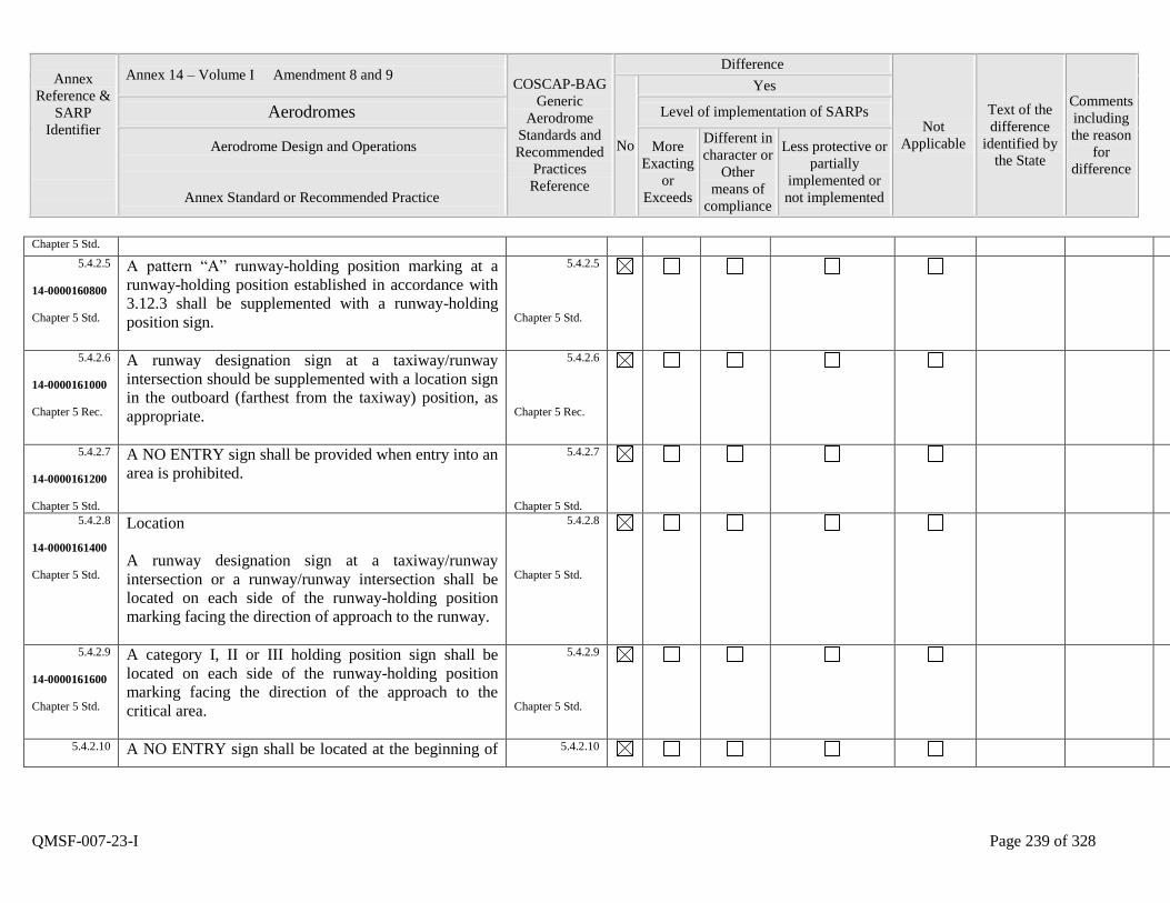
Annex
Reference &
SARP
Identifier
Annex 14 – Volume I Amendment 8 and 9 COSCAP-BAG
Generic
Aerodrome
Standards and
Recommended
Practices
Reference
Difference
Not
Applicable
Text of the
difference
identified by
the State
Comments
including
the reason
for
difference
No
Yes
Aerodromes Level of implementation of SARPs
Aerodrome Design and Operations
Annex Standard or Recommended Practice
More
Exacting
or
Exceeds
Different in
character or
Other
means of
compliance
Less protective or
partially
implemented or
not implemented
QMSF-007-23-I Page 239 of 328
Chapter 5 Std. 5.4.2.5
14-0000160800
Chapter 5 Std.
A pattern “A” runway-holding position marking at a
runway-holding position established in accordance with
3.12.3 shall be supplemented with a runway-holding
position sign.
5.4.2.5
Chapter 5 Std.
5.4.2.6
14-0000161000
Chapter 5 Rec.
A runway designation sign at a taxiway/runway
intersection should be supplemented with a location sign
in the outboard (farthest from the taxiway) position, as
appropriate.
5.4.2.6
Chapter 5 Rec.
5.4.2.7
14-0000161200
Chapter 5 Std.
A NO ENTRY sign shall be provided when entry into an
area is prohibited.
5.4.2.7
Chapter 5 Std.
5.4.2.8
14-0000161400
Chapter 5 Std.
Location
A runway designation sign at a taxiway/runway
intersection or a runway/runway intersection shall be
located on each side of the runway-holding position
marking facing the direction of approach to the runway.
5.4.2.8
Chapter 5 Std.
5.4.2.9
14-0000161600
Chapter 5 Std.
A category I, II or III holding position sign shall be
located on each side of the runway-holding position
marking facing the direction of the approach to the
critical area.
5.4.2.9
Chapter 5 Std.
5.4.2.10
A NO ENTRY sign shall be located at the beginning of 5.4.2.10
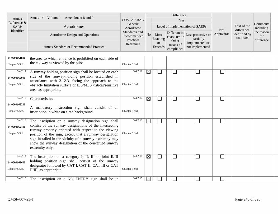
Annex
Reference &
SARP
Identifier
Annex 14 – Volume I Amendment 8 and 9 COSCAP-BAG
Generic
Aerodrome
Standards and
Recommended
Practices
Reference
Difference
Not
Applicable
Text of the
difference
identified by
the State
Comments
including
the reason
for
difference
No
Yes
Aerodromes Level of implementation of SARPs
Aerodrome Design and Operations
Annex Standard or Recommended Practice
More
Exacting
or
Exceeds
Different in
character or
Other
means of
compliance
Less protective or
partially
implemented or
not implemented
QMSF-007-23-I Page 240 of 328
14-0000161800
Chapter 5 Std.
the area to which entrance is prohibited on each side of
the taxiway as viewed by the pilot.
Chapter 5 Std.
5.4.2.11
14-0000162000
Chapter 5 Std.
A runway-holding position sign shall be located on each
side of the runway-holding position established in
accordance with 3.12.3, facing the approach to the
obstacle limitation surface or ILS/MLS critical/sensitive
area, as appropriate.
5.4.2.11
Chapter 5 Std.
5.4.2.12
14-0000162200
Chapter 5 Std.
Characteristics
A mandatory instruction sign shall consist of an
inscription in white on a red background.
5.4.2.12
Chapter 5 Std.
5.4.2.13
14-0000162400
Chapter 5 Std.
The inscription on a runway designation sign shall
consist of the runway designations of the intersecting
runway properly oriented with respect to the viewing
position of the sign, except that a runway designation
sign installed in the vicinity of a runway extremity may
show the runway designation of the concerned runway
extremity only.
5.4.2.13
Chapter 5 Std.
5.4.2.14
14-0000162600
Chapter 5 Std.
The inscription on a category I, II, III or joint II/III
holding position sign shall consist of the runway
designator followed by CAT I, CAT II, CAT III or CAT
II/III, as appropriate.
5.4.2.14
Chapter 5 Std.
5.4.2.15 The inscription on a NO ENTRY sign shall be in 5.4.2.15
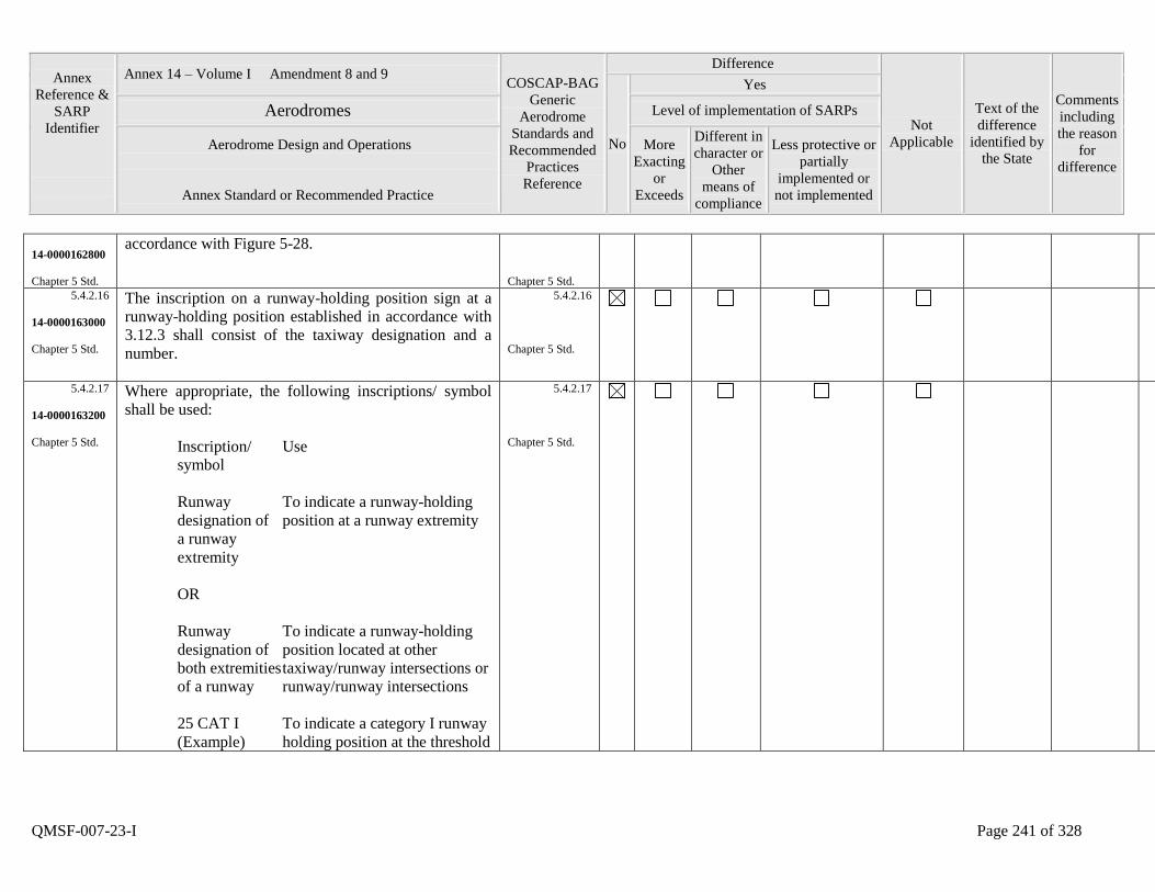
Annex
Reference &
SARP
Identifier
Annex 14 – Volume I Amendment 8 and 9 COSCAP-BAG
Generic
Aerodrome
Standards and
Recommended
Practices
Reference
Difference
Not
Applicable
Text of the
difference
identified by
the State
Comments
including
the reason
for
difference
No
Yes
Aerodromes Level of implementation of SARPs
Aerodrome Design and Operations
Annex Standard or Recommended Practice
More
Exacting
or
Exceeds
Different in
character or
Other
means of
compliance
Less protective or
partially
implemented or
not implemented
QMSF-007-23-I Page 241 of 328
14-0000162800
Chapter 5 Std.
accordance with Figure 5-28.
Chapter 5 Std.
5.4.2.16
14-0000163000
Chapter 5 Std.
The inscription on a runway-holding position sign at a
runway-holding position established in accordance with
3.12.3 shall consist of the taxiway designation and a
number.
5.4.2.16
Chapter 5 Std.
5.4.2.17
14-0000163200
Chapter 5 Std.
Where appropriate, the following inscriptions/ symbol
shall be used:
Inscription/ Use
symbol
Runway To indicate a runway-holding
designation of position at a runway extremity
a runway
extremity
OR
Runway To indicate a runway-holding
designation of position located at other
both extremities taxiway/runway intersections or
of a runway runway/runway intersections
25 CAT I To indicate a category I runway
(Example) holding position at the threshold
5.4.2.17
Chapter 5 Std.
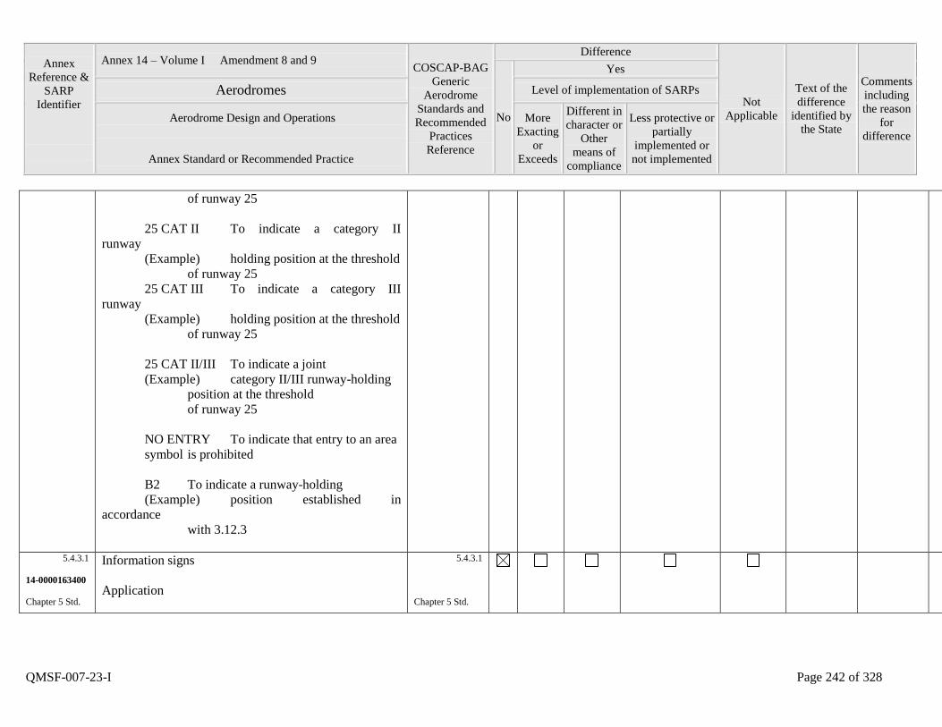
Annex
Reference &
SARP
Identifier
Annex 14 – Volume I Amendment 8 and 9 COSCAP-BAG
Generic
Aerodrome
Standards and
Recommended
Practices
Reference
Difference
Not
Applicable
Text of the
difference
identified by
the State
Comments
including
the reason
for
difference
No
Yes
Aerodromes Level of implementation of SARPs
Aerodrome Design and Operations
Annex Standard or Recommended Practice
More
Exacting
or
Exceeds
Different in
character or
Other
means of
compliance
Less protective or
partially
implemented or
not implemented
QMSF-007-23-I Page 242 of 328
of runway 25
25 CAT II To indicate a category II
runway
(Example) holding position at the threshold
of runway 25
25 CAT III To indicate a category III
runway
(Example) holding position at the threshold
of runway 25
25 CAT II/III To indicate a joint
(Example) category II/III runway-holding
position at the threshold
of runway 25
NO ENTRY To indicate that entry to an area
symbol is prohibited
B2 To indicate a runway-holding
(Example) position established in
accordance
with 3.12.3
5.4.3.1
14-0000163400
Chapter 5 Std.
Information signs
Application
5.4.3.1
Chapter 5 Std.
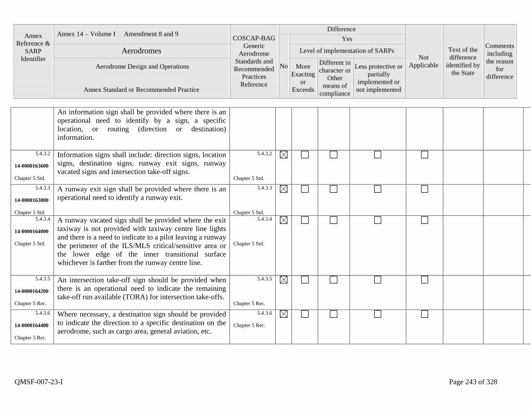
Annex
Reference &
SARP
Identifier
Annex 14 – Volume I Amendment 8 and 9 COSCAP-BAG
Generic
Aerodrome
Standards and
Recommended
Practices
Reference
Difference
Not
Applicable
Text of the
difference
identified by
the State
Comments
including
the reason
for
difference
No
Yes
Aerodromes Level of implementation of SARPs
Aerodrome Design and Operations
Annex Standard or Recommended Practice
More
Exacting
or
Exceeds
Different in
character or
Other
means of
compliance
Less protective or
partially
implemented or
not implemented
QMSF-007-23-I Page 243 of 328
An information sign shall be provided where there is an
operational need to identify by a sign, a specific
location, or routing (direction or destination)
information.
5.4.3.2
14-0000163600
Chapter 5 Std.
Information signs shall include: direction signs, location
signs, destination signs, runway exit signs, runway
vacated signs and intersection take-off signs.
5.4.3.2
Chapter 5 Std.
5.4.3.3
14-0000163800
Chapter 5 Std.
A runway exit sign shall be provided where there is an
operational need to identify a runway exit.
5.4.3.3
Chapter 5 Std.
5.4.3.4
14-0000164000
Chapter 5 Std.
A runway vacated sign shall be provided where the exit
taxiway is not provided with taxiway centre line lights
and there is a need to indicate to a pilot leaving a runway
the perimeter of the ILS/MLS critical/sensitive area or
the lower edge of the inner transitional surface
whichever is farther from the runway centre line.
5.4.3.4
Chapter 5 Std.
5.4.3.5
14-0000164200
Chapter 5 Rec.
An intersection take-off sign should be provided when
there is an operational need to indicate the remaining
take-off run available (TORA) for intersection take-offs.
5.4.3.5
Chapter 5 Rec.
5.4.3.6
14-0000164400
Chapter 5 Rec.
Where necessary, a destination sign should be provided
to indicate the direction to a specific destination on the
aerodrome, such as cargo area, general aviation, etc.
5.4.3.6
Chapter 5 Rec.
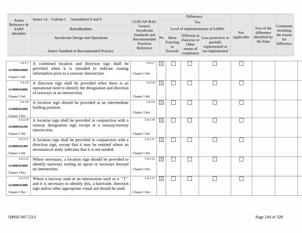
Annex
Reference &
SARP
Identifier
Annex 14 – Volume I Amendment 8 and 9 COSCAP-BAG
Generic
Aerodrome
Standards and
Recommended
Practices
Reference
Difference
Not
Applicable
Text of the
difference
identified by
the State
Comments
including
the reason
for
difference
No
Yes
Aerodromes Level of implementation of SARPs
Aerodrome Design and Operations
Annex Standard or Recommended Practice
More
Exacting
or
Exceeds
Different in
character or
Other
means of
compliance
Less protective or
partially
implemented or
not implemented
QMSF-007-23-I Page 244 of 328
5.4.3.7
14-0000164600
Chapter 5 Std.
A combined location and direction sign shall be
provided when it is intended to indicate routing
information prior to a taxiway intersection.
5.4.3.7
Chapter 5 Std.
5.4.3.8
14-0000164800
Chapter 5 Std.
A direction sign shall be provided when there is an
operational need to identify the designation and direction
of taxiways at an intersection.
5.4.3.8
Chapter 5 Std.
5.4.3.9
14-0000165000
Chapter 5 Rec.
A location sign should be provided at an intermediate
holding position.
5.4.3.9
Chapter 5 Rec.
5.4.3.10
14-0000165200
Chapter 5 Std.
A location sign shall be provided in conjunction with a
runway designation sign except at a runway/runway
intersection.
5.4.3.10
Chapter 5 Std.
5.4.3.11
14-0000165400
Chapter 5 Std.
A location sign shall be provided in conjunction with a
direction sign, except that it may be omitted where an
aeronautical study indicates that it is not needed.
5.4.3.11
Chapter 5 Std.
5.4.3.12
14-0000165600
Chapter 5 Rec.
Where necessary, a location sign should be provided to
identify taxiways exiting an apron or taxiways beyond
an intersection.
5.4.3.12
Chapter 5 Rec.
5.4.3.13
14-0000165800
Chapter 5 Rec.
Where a taxiway ends at an intersection such as a „‟T‟„
and it is necessary to identify this, a barricade, direction
sign and/or other appropriate visual aid should be used.
5.4.3.13
Chapter 5 Rec.
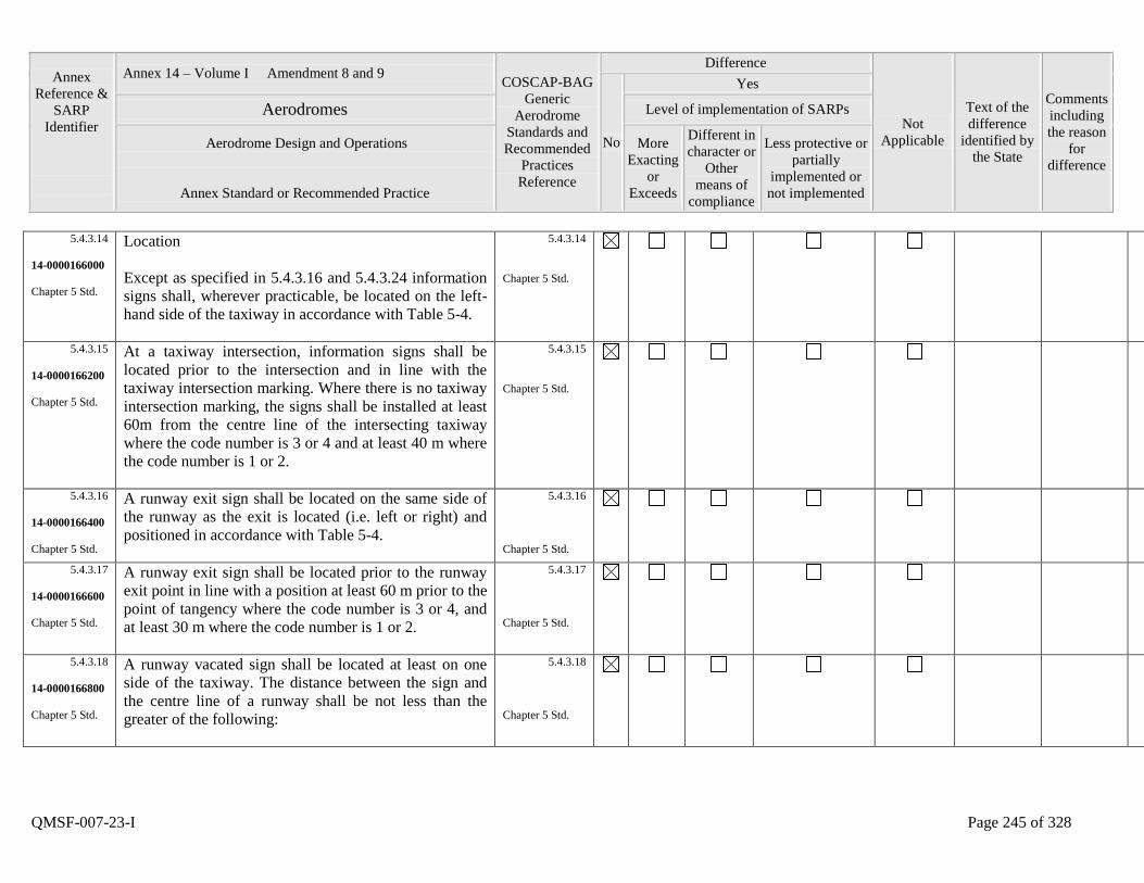
Annex
Reference &
SARP
Identifier
Annex 14 – Volume I Amendment 8 and 9 COSCAP-BAG
Generic
Aerodrome
Standards and
Recommended
Practices
Reference
Difference
Not
Applicable
Text of the
difference
identified by
the State
Comments
including
the reason
for
difference
No
Yes
Aerodromes Level of implementation of SARPs
Aerodrome Design and Operations
Annex Standard or Recommended Practice
More
Exacting
or
Exceeds
Different in
character or
Other
means of
compliance
Less protective or
partially
implemented or
not implemented
QMSF-007-23-I Page 245 of 328
5.4.3.14
14-0000166000
Chapter 5 Std.
Location
Except as specified in 5.4.3.16 and 5.4.3.24 information
signs shall, wherever practicable, be located on the left-
hand side of the taxiway in accordance with Table 5-4.
5.4.3.14
Chapter 5 Std.
5.4.3.15
14-0000166200
Chapter 5 Std.
At a taxiway intersection, information signs shall be
located prior to the intersection and in line with the
taxiway intersection marking. Where there is no taxiway
intersection marking, the signs shall be installed at least
60m from the centre line of the intersecting taxiway
where the code number is 3 or 4 and at least 40 m where
the code number is 1 or 2.
5.4.3.15
Chapter 5 Std.
5.4.3.16
14-0000166400
Chapter 5 Std.
A runway exit sign shall be located on the same side of
the runway as the exit is located (i.e. left or right) and
positioned in accordance with Table 5-4.
5.4.3.16
Chapter 5 Std.
5.4.3.17
14-0000166600
Chapter 5 Std.
A runway exit sign shall be located prior to the runway
exit point in line with a position at least 60 m prior to the
point of tangency where the code number is 3 or 4, and
at least 30 m where the code number is 1 or 2.
5.4.3.17
Chapter 5 Std.
5.4.3.18
14-0000166800
Chapter 5 Std.
A runway vacated sign shall be located at least on one
side of the taxiway. The distance between the sign and
the centre line of a runway shall be not less than the
greater of the following:
5.4.3.18
Chapter 5 Std.
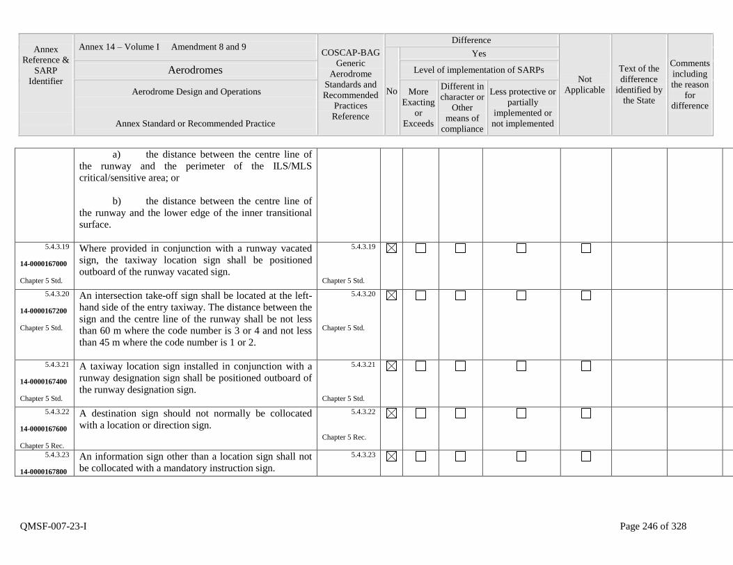
Annex
Reference &
SARP
Identifier
Annex 14 – Volume I Amendment 8 and 9 COSCAP-BAG
Generic
Aerodrome
Standards and
Recommended
Practices
Reference
Difference
Not
Applicable
Text of the
difference
identified by
the State
Comments
including
the reason
for
difference
No
Yes
Aerodromes Level of implementation of SARPs
Aerodrome Design and Operations
Annex Standard or Recommended Practice
More
Exacting
or
Exceeds
Different in
character or
Other
means of
compliance
Less protective or
partially
implemented or
not implemented
QMSF-007-23-I Page 246 of 328
a) the distance between the centre line of
the runway and the perimeter of the ILS/MLS
critical/sensitive area; or
b) the distance between the centre line of
the runway and the lower edge of the inner transitional
surface.
5.4.3.19
14-0000167000
Chapter 5 Std.
Where provided in conjunction with a runway vacated
sign, the taxiway location sign shall be positioned
outboard of the runway vacated sign.
5.4.3.19
Chapter 5 Std.
5.4.3.20
14-0000167200
Chapter 5 Std.
An intersection take-off sign shall be located at the left-
hand side of the entry taxiway. The distance between the
sign and the centre line of the runway shall be not less
than 60 m where the code number is 3 or 4 and not less
than 45 m where the code number is 1 or 2.
5.4.3.20
Chapter 5 Std.
5.4.3.21
14-0000167400
Chapter 5 Std.
A taxiway location sign installed in conjunction with a
runway designation sign shall be positioned outboard of
the runway designation sign.
5.4.3.21
Chapter 5 Std.
5.4.3.22
14-0000167600
Chapter 5 Rec.
A destination sign should not normally be collocated
with a location or direction sign.
5.4.3.22
Chapter 5 Rec.
5.4.3.23
14-0000167800
An information sign other than a location sign shall not
be collocated with a mandatory instruction sign.
5.4.3.23
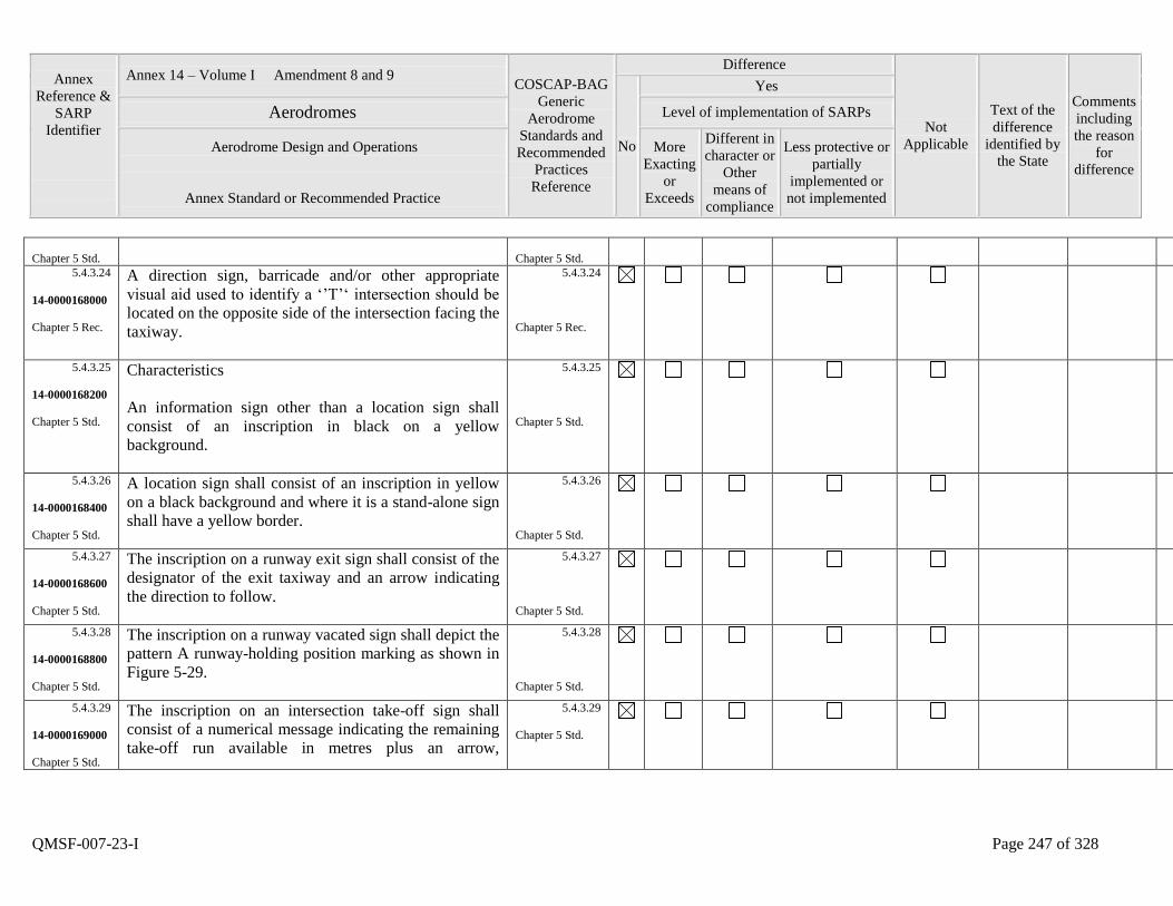
Annex
Reference &
SARP
Identifier
Annex 14 – Volume I Amendment 8 and 9 COSCAP-BAG
Generic
Aerodrome
Standards and
Recommended
Practices
Reference
Difference
Not
Applicable
Text of the
difference
identified by
the State
Comments
including
the reason
for
difference
No
Yes
Aerodromes Level of implementation of SARPs
Aerodrome Design and Operations
Annex Standard or Recommended Practice
More
Exacting
or
Exceeds
Different in
character or
Other
means of
compliance
Less protective or
partially
implemented or
not implemented
QMSF-007-23-I Page 247 of 328
Chapter 5 Std.
Chapter 5 Std.
5.4.3.24
14-0000168000
Chapter 5 Rec.
A direction sign, barricade and/or other appropriate
visual aid used to identify a „‟T‟„ intersection should be
located on the opposite side of the intersection facing the
taxiway.
5.4.3.24
Chapter 5 Rec.
5.4.3.25
14-0000168200
Chapter 5 Std.
Characteristics
An information sign other than a location sign shall
consist of an inscription in black on a yellow
background.
5.4.3.25
Chapter 5 Std.
5.4.3.26
14-0000168400
Chapter 5 Std.
A location sign shall consist of an inscription in yellow
on a black background and where it is a stand-alone sign
shall have a yellow border.
5.4.3.26
Chapter 5 Std.
5.4.3.27
14-0000168600
Chapter 5 Std.
The inscription on a runway exit sign shall consist of the
designator of the exit taxiway and an arrow indicating
the direction to follow.
5.4.3.27
Chapter 5 Std.
5.4.3.28
14-0000168800
Chapter 5 Std.
The inscription on a runway vacated sign shall depict the
pattern A runway-holding position marking as shown in
Figure 5-29.
5.4.3.28
Chapter 5 Std.
5.4.3.29
14-0000169000
Chapter 5 Std.
The inscription on an intersection take-off sign shall
consist of a numerical message indicating the remaining
take-off run available in metres plus an arrow,
5.4.3.29
Chapter 5 Std.
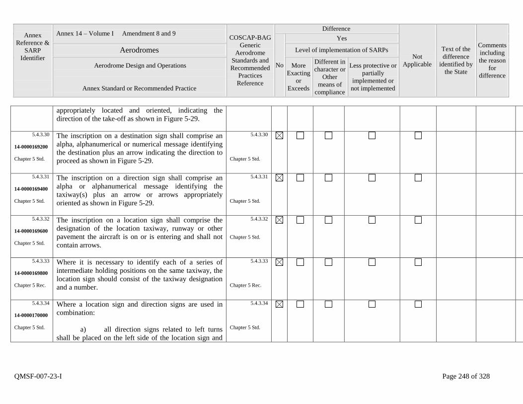
Annex
Reference &
SARP
Identifier
Annex 14 – Volume I Amendment 8 and 9 COSCAP-BAG
Generic
Aerodrome
Standards and
Recommended
Practices
Reference
Difference
Not
Applicable
Text of the
difference
identified by
the State
Comments
including
the reason
for
difference
No
Yes
Aerodromes Level of implementation of SARPs
Aerodrome Design and Operations
Annex Standard or Recommended Practice
More
Exacting
or
Exceeds
Different in
character or
Other
means of
compliance
Less protective or
partially
implemented or
not implemented
QMSF-007-23-I Page 248 of 328
appropriately located and oriented, indicating the
direction of the take-off as shown in Figure 5-29.
5.4.3.30
14-0000169200
Chapter 5 Std.
The inscription on a destination sign shall comprise an
alpha, alphanumerical or numerical message identifying
the destination plus an arrow indicating the direction to
proceed as shown in Figure 5-29.
5.4.3.30
Chapter 5 Std.
5.4.3.31
14-0000169400
Chapter 5 Std.
The inscription on a direction sign shall comprise an
alpha or alphanumerical message identifying the
taxiway(s) plus an arrow or arrows appropriately
oriented as shown in Figure 5-29.
5.4.3.31
Chapter 5 Std.
5.4.3.32
14-0000169600
Chapter 5 Std.
The inscription on a location sign shall comprise the
designation of the location taxiway, runway or other
pavement the aircraft is on or is entering and shall not
contain arrows.
5.4.3.32
Chapter 5 Std.
5.4.3.33
14-0000169800
Chapter 5 Rec.
Where it is necessary to identify each of a series of
intermediate holding positions on the same taxiway, the
location sign should consist of the taxiway designation
and a number.
5.4.3.33
Chapter 5 Rec.
5.4.3.34
14-0000170000
Chapter 5 Std.
Where a location sign and direction signs are used in
combination:
a) all direction signs related to left turns
shall be placed on the left side of the location sign and
5.4.3.34
Chapter 5 Std.
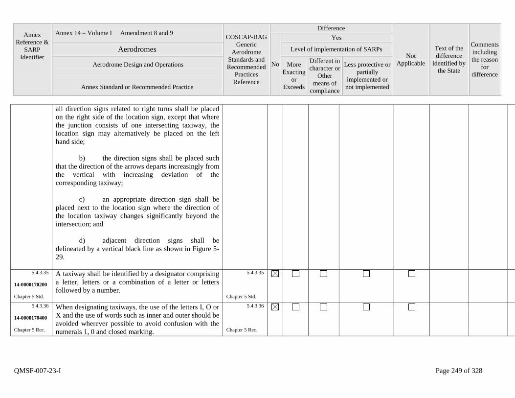
Annex
Reference &
SARP
Identifier
Annex 14 – Volume I Amendment 8 and 9 COSCAP-BAG
Generic
Aerodrome
Standards and
Recommended
Practices
Reference
Difference
Not
Applicable
Text of the
difference
identified by
the State
Comments
including
the reason
for
difference
No
Yes
Aerodromes Level of implementation of SARPs
Aerodrome Design and Operations
Annex Standard or Recommended Practice
More
Exacting
or
Exceeds
Different in
character or
Other
means of
compliance
Less protective or
partially
implemented or
not implemented
QMSF-007-23-I Page 249 of 328
all direction signs related to right turns shall be placed
on the right side of the location sign, except that where
the junction consists of one intersecting taxiway, the
location sign may alternatively be placed on the left
hand side;
b) the direction signs shall be placed such
that the direction of the arrows departs increasingly from
the vertical with increasing deviation of the
corresponding taxiway;
c) an appropriate direction sign shall be
placed next to the location sign where the direction of
the location taxiway changes significantly beyond the
intersection; and
d) adjacent direction signs shall be
delineated by a vertical black line as shown in Figure 5-
29.
5.4.3.35
14-0000170200
Chapter 5 Std.
A taxiway shall be identified by a designator comprising
a letter, letters or a combination of a letter or letters
followed by a number.
5.4.3.35
Chapter 5 Std.
5.4.3.36
14-0000170400
Chapter 5 Rec.
When designating taxiways, the use of the letters I, O or
X and the use of words such as inner and outer should be
avoided wherever possible to avoid confusion with the
numerals 1, 0 and closed marking.
5.4.3.36
Chapter 5 Rec.
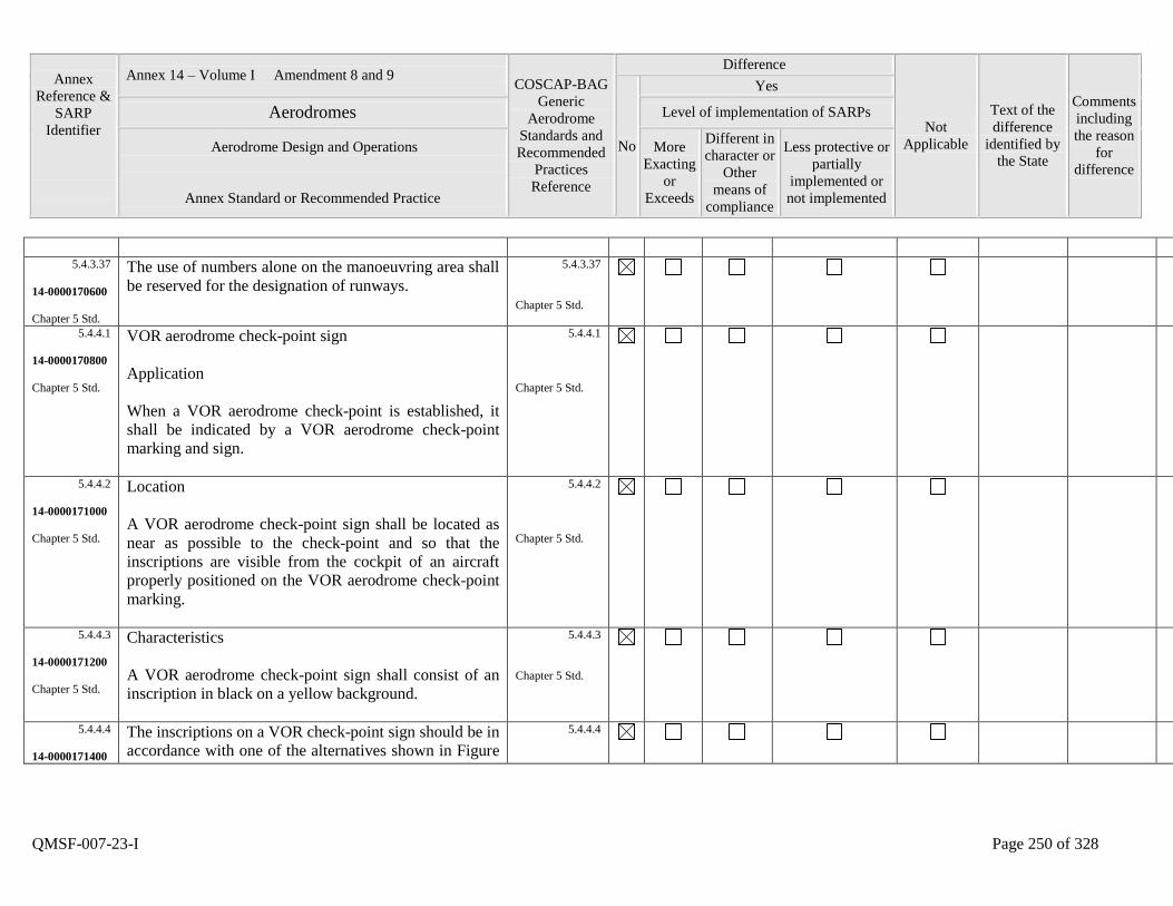
Annex
Reference &
SARP
Identifier
Annex 14 – Volume I Amendment 8 and 9 COSCAP-BAG
Generic
Aerodrome
Standards and
Recommended
Practices
Reference
Difference
Not
Applicable
Text of the
difference
identified by
the State
Comments
including
the reason
for
difference
No
Yes
Aerodromes Level of implementation of SARPs
Aerodrome Design and Operations
Annex Standard or Recommended Practice
More
Exacting
or
Exceeds
Different in
character or
Other
means of
compliance
Less protective or
partially
implemented or
not implemented
QMSF-007-23-I Page 250 of 328
5.4.3.37
14-0000170600
Chapter 5 Std.
The use of numbers alone on the manoeuvring area shall
be reserved for the designation of runways.
5.4.3.37
Chapter 5 Std.
5.4.4.1
14-0000170800
Chapter 5 Std.
VOR aerodrome check-point sign
Application
When a VOR aerodrome check-point is established, it
shall be indicated by a VOR aerodrome check-point
marking and sign.
5.4.4.1
Chapter 5 Std.
5.4.4.2
14-0000171000
Chapter 5 Std.
Location
A VOR aerodrome check-point sign shall be located as
near as possible to the check-point and so that the
inscriptions are visible from the cockpit of an aircraft
properly positioned on the VOR aerodrome check-point
marking.
5.4.4.2
Chapter 5 Std.
5.4.4.3
14-0000171200
Chapter 5 Std.
Characteristics
A VOR aerodrome check-point sign shall consist of an
inscription in black on a yellow background.
5.4.4.3
Chapter 5 Std.
5.4.4.4
14-0000171400
The inscriptions on a VOR check-point sign should be in
accordance with one of the alternatives shown in Figure
5.4.4.4
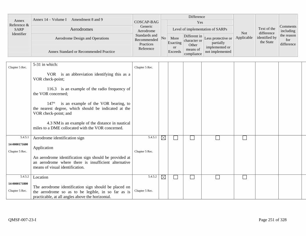
Annex
Reference &
SARP
Identifier
Annex 14 – Volume I Amendment 8 and 9 COSCAP-BAG
Generic
Aerodrome
Standards and
Recommended
Practices
Reference
Difference
Not
Applicable
Text of the
difference
identified by
the State
Comments
including
the reason
for
difference
No
Yes
Aerodromes Level of implementation of SARPs
Aerodrome Design and Operations
Annex Standard or Recommended Practice
More
Exacting
or
Exceeds
Different in
character or
Other
means of
compliance
Less protective or
partially
implemented or
not implemented
QMSF-007-23-I Page 251 of 328
Chapter 5 Rec. 5-31 in which:
VOR is an abbreviation identifying this as a
VOR check-point;
116.3 is an example of the radio frequency of
the VOR concerned;
147° is an example of the VOR bearing, to
the nearest degree, which should be indicated at the
VOR check-point; and
4.3 NM is an example of the distance in nautical
miles to a DME collocated with the VOR concerned.
Chapter 5 Rec.
5.4.5.1
14-0000171600
Chapter 5 Rec.
Aerodrome identification sign
Application
An aerodrome identification sign should be provided at
an aerodrome where there is insufficient alternative
means of visual identification.
5.4.5.1
Chapter 5 Rec.
5.4.5.2
14-0000171800
Chapter 5 Rec.
Location
The aerodrome identification sign should be placed on
the aerodrome so as to be legible, in so far as is
practicable, at all angles above the horizontal.
5.4.5.2
Chapter 5 Rec.
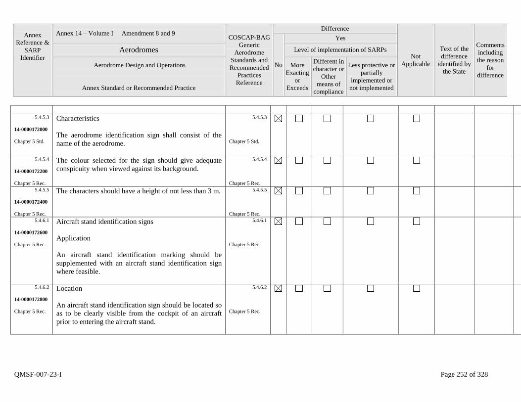
Annex
Reference &
SARP
Identifier
Annex 14 – Volume I Amendment 8 and 9 COSCAP-BAG
Generic
Aerodrome
Standards and
Recommended
Practices
Reference
Difference
Not
Applicable
Text of the
difference
identified by
the State
Comments
including
the reason
for
difference
No
Yes
Aerodromes Level of implementation of SARPs
Aerodrome Design and Operations
Annex Standard or Recommended Practice
More
Exacting
or
Exceeds
Different in
character or
Other
means of
compliance
Less protective or
partially
implemented or
not implemented
QMSF-007-23-I Page 252 of 328
5.4.5.3
14-0000172000
Chapter 5 Std.
Characteristics
The aerodrome identification sign shall consist of the
name of the aerodrome.
5.4.5.3
Chapter 5 Std.
5.4.5.4
14-0000172200
Chapter 5 Rec.
The colour selected for the sign should give adequate
conspicuity when viewed against its background.
5.4.5.4
Chapter 5 Rec.
5.4.5.5
14-0000172400
Chapter 5 Rec.
The characters should have a height of not less than 3 m.
5.4.5.5
Chapter 5 Rec.
5.4.6.1
14-0000172600
Chapter 5 Rec.
Aircraft stand identification signs
Application
An aircraft stand identification marking should be
supplemented with an aircraft stand identification sign
where feasible.
5.4.6.1
Chapter 5 Rec.
5.4.6.2
14-0000172800
Chapter 5 Rec.
Location
An aircraft stand identification sign should be located so
as to be clearly visible from the cockpit of an aircraft
prior to entering the aircraft stand.
5.4.6.2
Chapter 5 Rec.
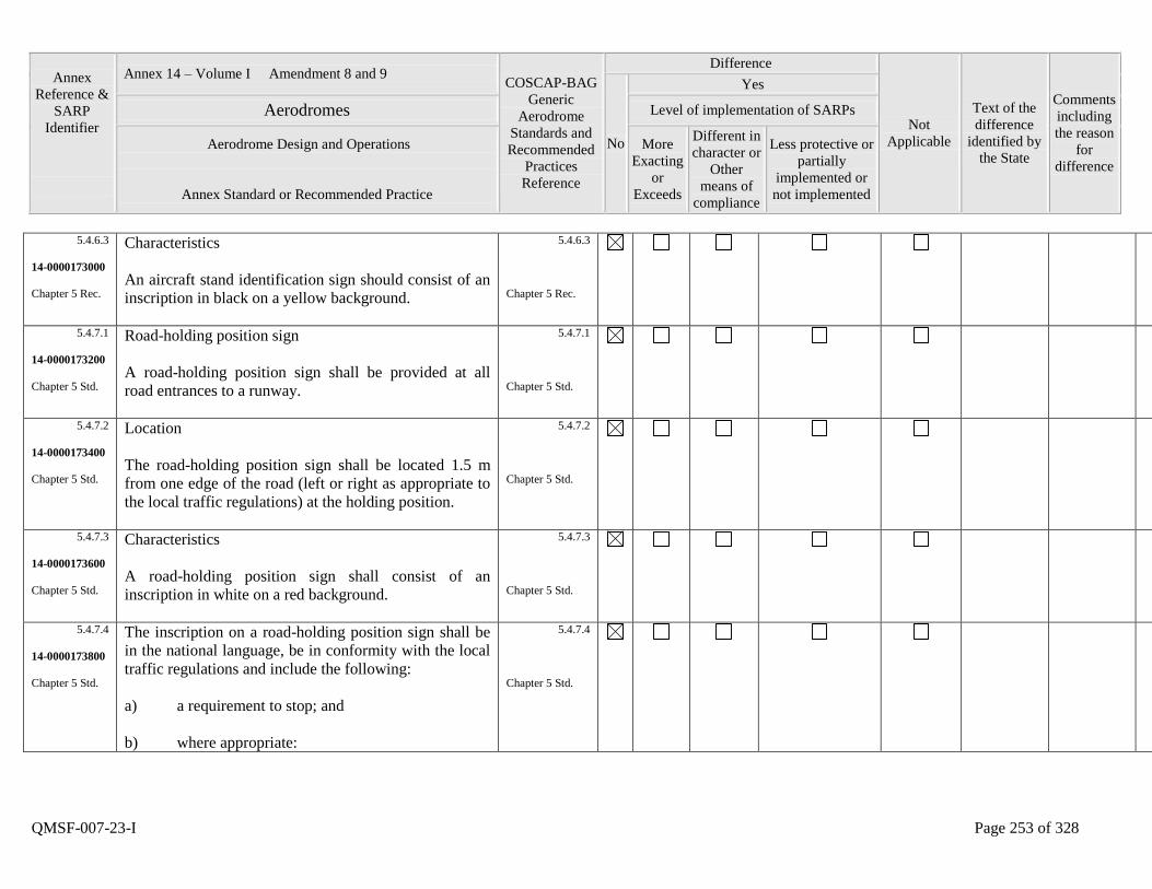
Annex
Reference &
SARP
Identifier
Annex 14 – Volume I Amendment 8 and 9 COSCAP-BAG
Generic
Aerodrome
Standards and
Recommended
Practices
Reference
Difference
Not
Applicable
Text of the
difference
identified by
the State
Comments
including
the reason
for
difference
No
Yes
Aerodromes Level of implementation of SARPs
Aerodrome Design and Operations
Annex Standard or Recommended Practice
More
Exacting
or
Exceeds
Different in
character or
Other
means of
compliance
Less protective or
partially
implemented or
not implemented
QMSF-007-23-I Page 253 of 328
5.4.6.3
14-0000173000
Chapter 5 Rec.
Characteristics
An aircraft stand identification sign should consist of an
inscription in black on a yellow background.
5.4.6.3
Chapter 5 Rec.
5.4.7.1
14-0000173200
Chapter 5 Std.
Road-holding position sign
A road-holding position sign shall be provided at all
road entrances to a runway.
5.4.7.1
Chapter 5 Std.
5.4.7.2
14-0000173400
Chapter 5 Std.
Location
The road-holding position sign shall be located 1.5 m
from one edge of the road (left or right as appropriate to
the local traffic regulations) at the holding position.
5.4.7.2
Chapter 5 Std.
5.4.7.3
14-0000173600
Chapter 5 Std.
Characteristics
A road-holding position sign shall consist of an
inscription in white on a red background.
5.4.7.3
Chapter 5 Std.
5.4.7.4
14-0000173800
Chapter 5 Std.
The inscription on a road-holding position sign shall be
in the national language, be in conformity with the local
traffic regulations and include the following:
a) a requirement to stop; and
b) where appropriate:
5.4.7.4
Chapter 5 Std.
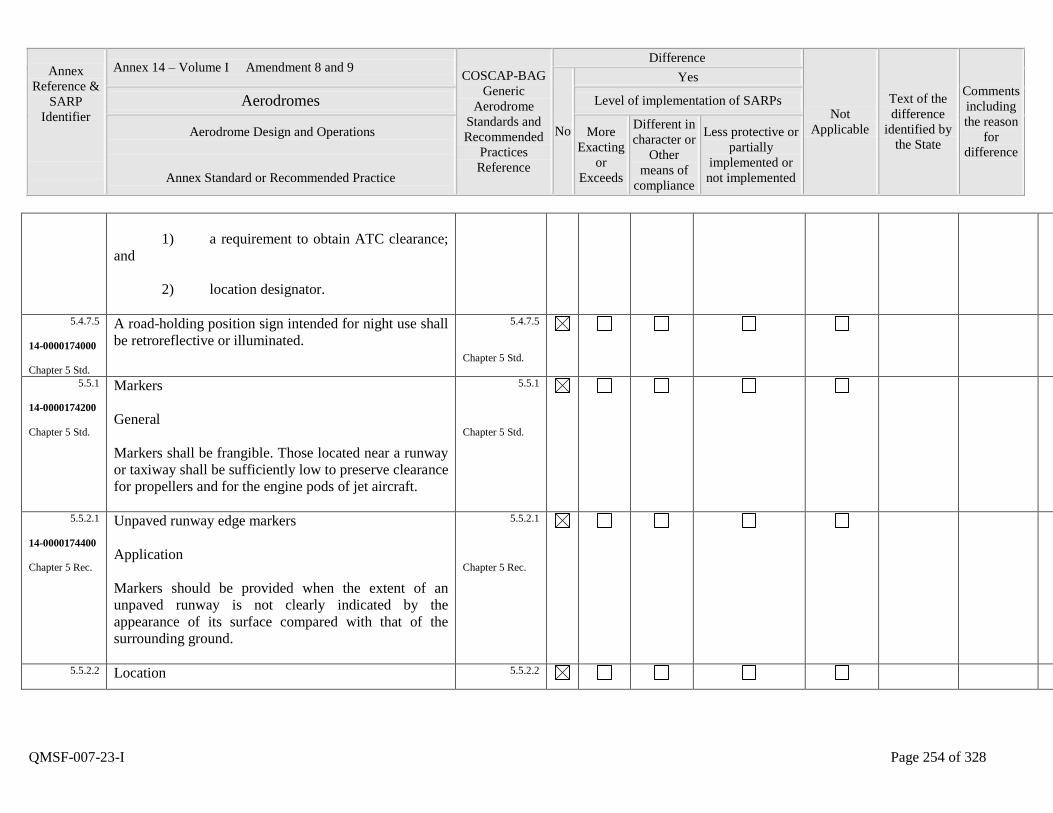
Annex
Reference &
SARP
Identifier
Annex 14 – Volume I Amendment 8 and 9 COSCAP-BAG
Generic
Aerodrome
Standards and
Recommended
Practices
Reference
Difference
Not
Applicable
Text of the
difference
identified by
the State
Comments
including
the reason
for
difference
No
Yes
Aerodromes Level of implementation of SARPs
Aerodrome Design and Operations
Annex Standard or Recommended Practice
More
Exacting
or
Exceeds
Different in
character or
Other
means of
compliance
Less protective or
partially
implemented or
not implemented
QMSF-007-23-I Page 254 of 328
1) a requirement to obtain ATC clearance;
and
2) location designator.
5.4.7.5
14-0000174000
Chapter 5 Std.
A road-holding position sign intended for night use shall
be retroreflective or illuminated.
5.4.7.5
Chapter 5 Std.
5.5.1
14-0000174200
Chapter 5 Std.
Markers
General
Markers shall be frangible. Those located near a runway
or taxiway shall be sufficiently low to preserve clearance
for propellers and for the engine pods of jet aircraft.
5.5.1
Chapter 5 Std.
5.5.2.1
14-0000174400
Chapter 5 Rec.
Unpaved runway edge markers
Application
Markers should be provided when the extent of an
unpaved runway is not clearly indicated by the
appearance of its surface compared with that of the
surrounding ground.
5.5.2.1
Chapter 5 Rec.
5.5.2.2
Location 5.5.2.2
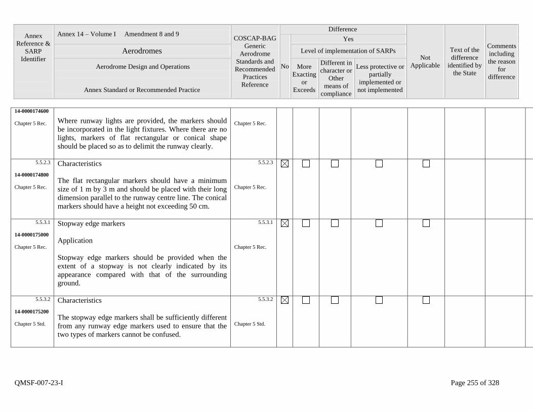
Annex
Reference &
SARP
Identifier
Annex 14 – Volume I Amendment 8 and 9 COSCAP-BAG
Generic
Aerodrome
Standards and
Recommended
Practices
Reference
Difference
Not
Applicable
Text of the
difference
identified by
the State
Comments
including
the reason
for
difference
No
Yes
Aerodromes Level of implementation of SARPs
Aerodrome Design and Operations
Annex Standard or Recommended Practice
More
Exacting
or
Exceeds
Different in
character or
Other
means of
compliance
Less protective or
partially
implemented or
not implemented
QMSF-007-23-I Page 255 of 328
14-0000174600
Chapter 5 Rec.
Where runway lights are provided, the markers should
be incorporated in the light fixtures. Where there are no
lights, markers of flat rectangular or conical shape
should be placed so as to delimit the runway clearly.
Chapter 5 Rec.
5.5.2.3
14-0000174800
Chapter 5 Rec.
Characteristics
The flat rectangular markers should have a minimum
size of 1 m by 3 m and should be placed with their long
dimension parallel to the runway centre line. The conical
markers should have a height not exceeding 50 cm.
5.5.2.3
Chapter 5 Rec.
5.5.3.1
14-0000175000
Chapter 5 Rec.
Stopway edge markers
Application
Stopway edge markers should be provided when the
extent of a stopway is not clearly indicated by its
appearance compared with that of the surrounding
ground.
5.5.3.1
Chapter 5 Rec.
5.5.3.2
14-0000175200
Chapter 5 Std.
Characteristics
The stopway edge markers shall be sufficiently different
from any runway edge markers used to ensure that the
two types of markers cannot be confused.
5.5.3.2
Chapter 5 Std.
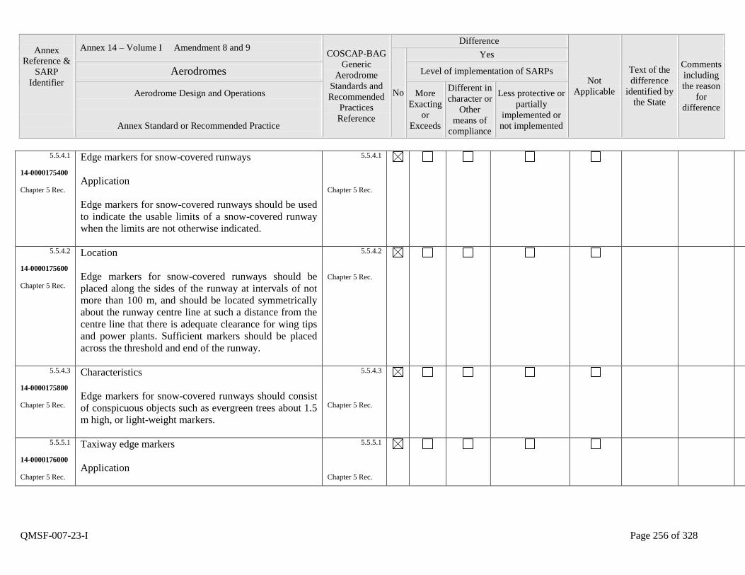
Annex
Reference &
SARP
Identifier
Annex 14 – Volume I Amendment 8 and 9 COSCAP-BAG
Generic
Aerodrome
Standards and
Recommended
Practices
Reference
Difference
Not
Applicable
Text of the
difference
identified by
the State
Comments
including
the reason
for
difference
No
Yes
Aerodromes Level of implementation of SARPs
Aerodrome Design and Operations
Annex Standard or Recommended Practice
More
Exacting
or
Exceeds
Different in
character or
Other
means of
compliance
Less protective or
partially
implemented or
not implemented
QMSF-007-23-I Page 256 of 328
5.5.4.1
14-0000175400
Chapter 5 Rec.
Edge markers for snow-covered runways
Application
Edge markers for snow-covered runways should be used
to indicate the usable limits of a snow-covered runway
when the limits are not otherwise indicated.
5.5.4.1
Chapter 5 Rec.
5.5.4.2
14-0000175600
Chapter 5 Rec.
Location
Edge markers for snow-covered runways should be
placed along the sides of the runway at intervals of not
more than 100 m, and should be located symmetrically
about the runway centre line at such a distance from the
centre line that there is adequate clearance for wing tips
and power plants. Sufficient markers should be placed
across the threshold and end of the runway.
5.5.4.2
Chapter 5 Rec.
5.5.4.3
14-0000175800
Chapter 5 Rec.
Characteristics
Edge markers for snow-covered runways should consist
of conspicuous objects such as evergreen trees about 1.5
m high, or light-weight markers.
5.5.4.3
Chapter 5 Rec.
5.5.5.1
14-0000176000
Chapter 5 Rec.
Taxiway edge markers
Application
5.5.5.1
Chapter 5 Rec.
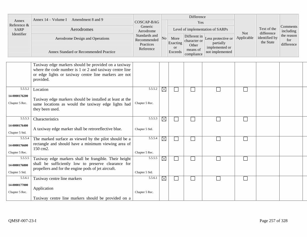
Annex
Reference &
SARP
Identifier
Annex 14 – Volume I Amendment 8 and 9 COSCAP-BAG
Generic
Aerodrome
Standards and
Recommended
Practices
Reference
Difference
Not
Applicable
Text of the
difference
identified by
the State
Comments
including
the reason
for
difference
No
Yes
Aerodromes Level of implementation of SARPs
Aerodrome Design and Operations
Annex Standard or Recommended Practice
More
Exacting
or
Exceeds
Different in
character or
Other
means of
compliance
Less protective or
partially
implemented or
not implemented
QMSF-007-23-I Page 257 of 328
Taxiway edge markers should be provided on a taxiway
where the code number is 1 or 2 and taxiway centre line
or edge lights or taxiway centre line markers are not
provided.
5.5.5.2
14-0000176200
Chapter 5 Rec.
Location
Taxiway edge markers should be installed at least at the
same locations as would the taxiway edge lights had
they been used.
5.5.5.2
Chapter 5 Rec.
5.5.5.3
14-0000176400
Chapter 5 Std.
Characteristics
A taxiway edge marker shall be retroreflective blue.
5.5.5.3
Chapter 5 Std.
5.5.5.4
14-0000176600
Chapter 5 Rec.
The marked surface as viewed by the pilot should be a
rectangle and should have a minimum viewing area of
150 cm2.
5.5.5.4
Chapter 5 Rec.
5.5.5.5
14-0000176800
Chapter 5 Std.
Taxiway edge markers shall be frangible. Their height
shall be sufficiently low to preserve clearance for
propellers and for the engine pods of jet aircraft.
5.5.5.5
Chapter 5 Std.
5.5.6.1
14-0000177000
Chapter 5 Rec.
Taxiway centre line markers
Application
Taxiway centre line markers should be provided on a
5.5.6.1
Chapter 5 Rec.
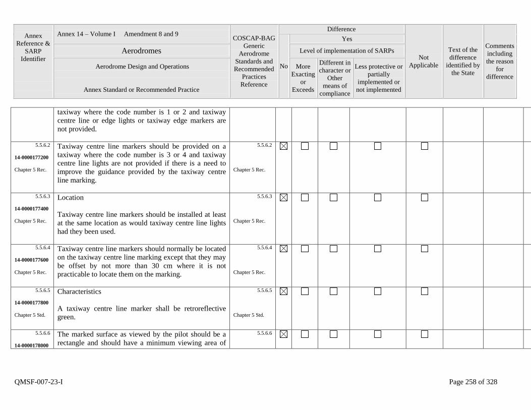
Annex
Reference &
SARP
Identifier
Annex 14 – Volume I Amendment 8 and 9 COSCAP-BAG
Generic
Aerodrome
Standards and
Recommended
Practices
Reference
Difference
Not
Applicable
Text of the
difference
identified by
the State
Comments
including
the reason
for
difference
No
Yes
Aerodromes Level of implementation of SARPs
Aerodrome Design and Operations
Annex Standard or Recommended Practice
More
Exacting
or
Exceeds
Different in
character or
Other
means of
compliance
Less protective or
partially
implemented or
not implemented
QMSF-007-23-I Page 258 of 328
taxiway where the code number is 1 or 2 and taxiway
centre line or edge lights or taxiway edge markers are
not provided.
5.5.6.2
14-0000177200
Chapter 5 Rec.
Taxiway centre line markers should be provided on a
taxiway where the code number is 3 or 4 and taxiway
centre line lights are not provided if there is a need to
improve the guidance provided by the taxiway centre
line marking.
5.5.6.2
Chapter 5 Rec.
5.5.6.3
14-0000177400
Chapter 5 Rec.
Location
Taxiway centre line markers should be installed at least
at the same location as would taxiway centre line lights
had they been used.
5.5.6.3
Chapter 5 Rec.
5.5.6.4
14-0000177600
Chapter 5 Rec.
Taxiway centre line markers should normally be located
on the taxiway centre line marking except that they may
be offset by not more than 30 cm where it is not
practicable to locate them on the marking.
5.5.6.4
Chapter 5 Rec.
5.5.6.5
14-0000177800
Chapter 5 Std.
Characteristics
A taxiway centre line marker shall be retroreflective
green.
5.5.6.5
Chapter 5 Std.
5.5.6.6
14-0000178000
The marked surface as viewed by the pilot should be a
rectangle and should have a minimum viewing area of
5.5.6.6
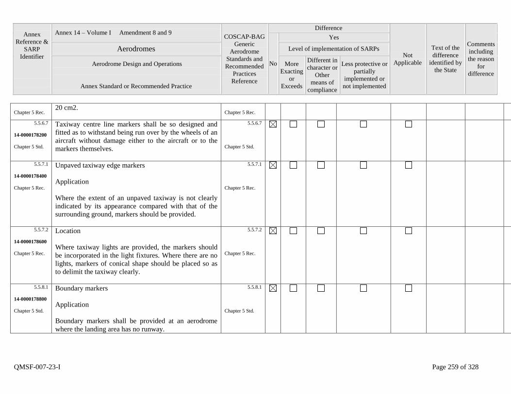
Annex
Reference &
SARP
Identifier
Annex 14 – Volume I Amendment 8 and 9 COSCAP-BAG
Generic
Aerodrome
Standards and
Recommended
Practices
Reference
Difference
Not
Applicable
Text of the
difference
identified by
the State
Comments
including
the reason
for
difference
No
Yes
Aerodromes Level of implementation of SARPs
Aerodrome Design and Operations
Annex Standard or Recommended Practice
More
Exacting
or
Exceeds
Different in
character or
Other
means of
compliance
Less protective or
partially
implemented or
not implemented
QMSF-007-23-I Page 259 of 328
Chapter 5 Rec. 20 cm2.
Chapter 5 Rec.
5.5.6.7
14-0000178200
Chapter 5 Std.
Taxiway centre line markers shall be so designed and
fitted as to withstand being run over by the wheels of an
aircraft without damage either to the aircraft or to the
markers themselves.
5.5.6.7
Chapter 5 Std.
5.5.7.1
14-0000178400
Chapter 5 Rec.
Unpaved taxiway edge markers
Application
Where the extent of an unpaved taxiway is not clearly
indicated by its appearance compared with that of the
surrounding ground, markers should be provided.
5.5.7.1
Chapter 5 Rec.
5.5.7.2
14-0000178600
Chapter 5 Rec.
Location
Where taxiway lights are provided, the markers should
be incorporated in the light fixtures. Where there are no
lights, markers of conical shape should be placed so as
to delimit the taxiway clearly.
5.5.7.2
Chapter 5 Rec.
5.5.8.1
14-0000178800
Chapter 5 Std.
Boundary markers
Application
Boundary markers shall be provided at an aerodrome
where the landing area has no runway.
5.5.8.1
Chapter 5 Std.
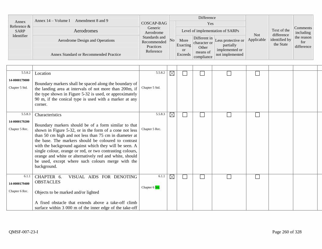
Annex
Reference &
SARP
Identifier
Annex 14 – Volume I Amendment 8 and 9 COSCAP-BAG
Generic
Aerodrome
Standards and
Recommended
Practices
Reference
Difference
Not
Applicable
Text of the
difference
identified by
the State
Comments
including
the reason
for
difference
No
Yes
Aerodromes Level of implementation of SARPs
Aerodrome Design and Operations
Annex Standard or Recommended Practice
More
Exacting
or
Exceeds
Different in
character or
Other
means of
compliance
Less protective or
partially
implemented or
not implemented
QMSF-007-23-I Page 260 of 328
5.5.8.2
14-0000179000
Chapter 5 Std.
Location
Boundary markers shall be spaced along the boundary of
the landing area at intervals of not more than 200m, if
the type shown in Figure 5-32 is used, or approximately
90 m, if the conical type is used with a marker at any
corner.
5.5.8.2
Chapter 5 Std.
5.5.8.3
14-0000179200
Chapter 5 Rec.
Characteristics
Boundary markers should be of a form similar to that
shown in Figure 5-32, or in the form of a cone not less
than 50 cm high and not less than 75 cm in diameter at
the base. The markers should be coloured to contrast
with the background against which they will be seen. A
single colour, orange or red, or two contrasting colours,
orange and white or alternatively red and white, should
be used, except where such colours merge with the
background.
5.5.8.3
Chapter 5 Rec.
6.1.1
14-0000179400
Chapter 6 Rec.
CHAPTER 6. VISUAL AIDS FOR DENOTING
OBSTACLES
Objects to be marked and/or lighted
A fixed obstacle that extends above a take-off climb
surface within 3 000 m of the inner edge of the take-off
6.1.1
Chapter 6 Std.
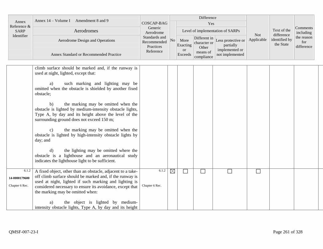
Annex
Reference &
SARP
Identifier
Annex 14 – Volume I Amendment 8 and 9 COSCAP-BAG
Generic
Aerodrome
Standards and
Recommended
Practices
Reference
Difference
Not
Applicable
Text of the
difference
identified by
the State
Comments
including
the reason
for
difference
No
Yes
Aerodromes Level of implementation of SARPs
Aerodrome Design and Operations
Annex Standard or Recommended Practice
More
Exacting
or
Exceeds
Different in
character or
Other
means of
compliance
Less protective or
partially
implemented or
not implemented
QMSF-007-23-I Page 261 of 328
climb surface should be marked and, if the runway is
used at night, lighted, except that:
a) such marking and lighting may be
omitted when the obstacle is shielded by another fixed
obstacle;
b) the marking may be omitted when the
obstacle is lighted by medium-intensity obstacle lights,
Type A, by day and its height above the level of the
surrounding ground does not exceed 150 m;
c) the marking may be omitted when the
obstacle is lighted by high-intensity obstacle lights by
day; and
d) the lighting may be omitted where the
obstacle is a lighthouse and an aeronautical study
indicates the lighthouse light to be sufficient.
6.1.2
14-0000179600
Chapter 6 Rec.
A fixed object, other than an obstacle, adjacent to a take-
off climb surface should be marked and, if the runway is
used at night, lighted if such marking and lighting is
considered necessary to ensure its avoidance, except that
the marking may be omitted when:
a) the object is lighted by medium-
intensity obstacle lights, Type A, by day and its height
6.1.2
Chapter 6 Rec.

Annex
Reference &
SARP
Identifier
Annex 14 – Volume I Amendment 8 and 9 COSCAP-BAG
Generic
Aerodrome
Standards and
Recommended
Practices
Reference
Difference
Not
Applicable
Text of the
difference
identified by
the State
Comments
including
the reason
for
difference
No
Yes
Aerodromes Level of implementation of SARPs
Aerodrome Design and Operations
Annex Standard or Recommended Practice
More
Exacting
or
Exceeds
Different in
character or
Other
means of
compliance
Less protective or
partially
implemented or
not implemented
QMSF-007-23-I Page 262 of 328
above the level of the surrounding ground does not
exceed 150 m; or
b) the object is lighted by high-intensity
obstacle lights by day.
6.1.3
14-0000179800
Chapter 6 Std.
A fixed obstacle that extends above an approach or
transitional surface within 3 000 m of the inner edge of
the approach surface shall be marked and, if the runway
is used at night, lighted, except that:
a) such marking and lighting may be
omitted when the obstacle is shielded by another fixed
obstacle;
b) the marking may be omitted when the
obstacle is lighted by medium-intensity obstacle lights,
Type A, by day and its height above the level of the
surrounding ground does not exceed 150 m;
c) the marking may be omitted when the
obstacle is lighted by high-intensity obstacle lights by
day; and
d) the lighting may be omitted where the
obstacle is a lighthouse and an aeronautical study
indicates the lighthouse light to be sufficient.
6.1.3
Chapter 6 Std.
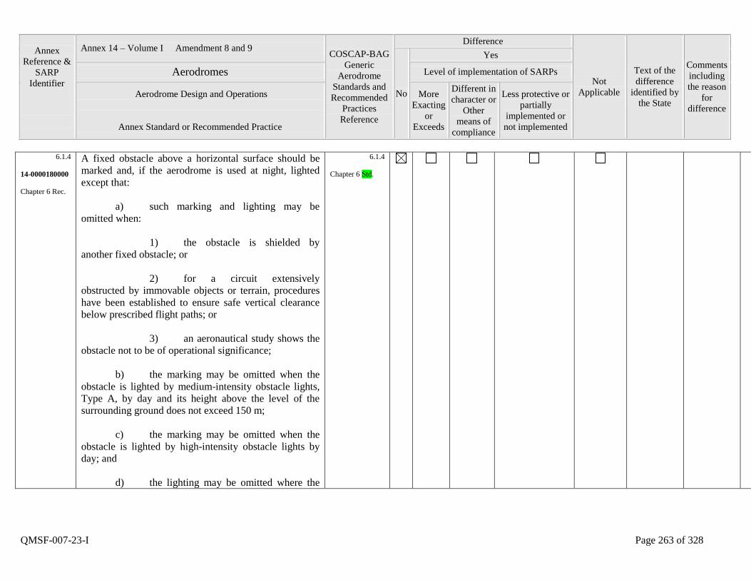
Annex
Reference &
SARP
Identifier
Annex 14 – Volume I Amendment 8 and 9 COSCAP-BAG
Generic
Aerodrome
Standards and
Recommended
Practices
Reference
Difference
Not
Applicable
Text of the
difference
identified by
the State
Comments
including
the reason
for
difference
No
Yes
Aerodromes Level of implementation of SARPs
Aerodrome Design and Operations
Annex Standard or Recommended Practice
More
Exacting
or
Exceeds
Different in
character or
Other
means of
compliance
Less protective or
partially
implemented or
not implemented
QMSF-007-23-I Page 263 of 328
6.1.4
14-0000180000
Chapter 6 Rec.
A fixed obstacle above a horizontal surface should be
marked and, if the aerodrome is used at night, lighted
except that:
a) such marking and lighting may be
omitted when:
1) the obstacle is shielded by
another fixed obstacle; or
2) for a circuit extensively
obstructed by immovable objects or terrain, procedures
have been established to ensure safe vertical clearance
below prescribed flight paths; or
3) an aeronautical study shows the
obstacle not to be of operational significance;
b) the marking may be omitted when the
obstacle is lighted by medium-intensity obstacle lights,
Type A, by day and its height above the level of the
surrounding ground does not exceed 150 m;
c) the marking may be omitted when the
obstacle is lighted by high-intensity obstacle lights by
day; and
d) the lighting may be omitted where the
6.1.4
Chapter 6 Std.
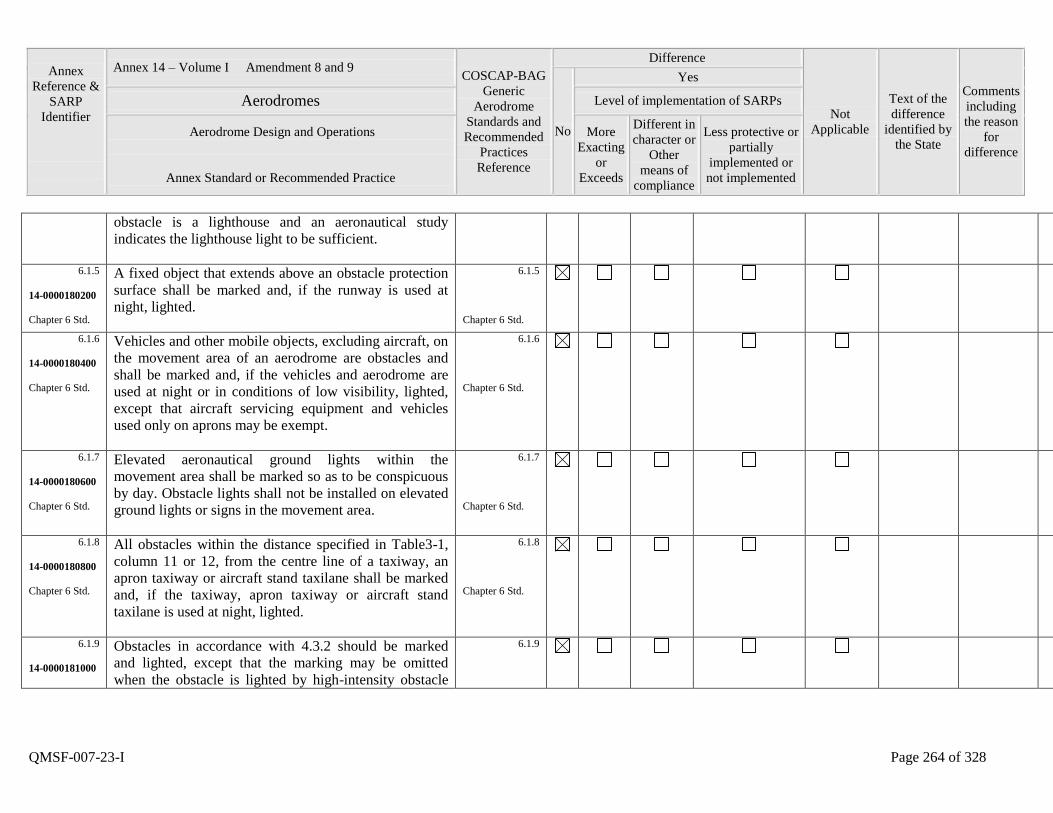
Annex
Reference &
SARP
Identifier
Annex 14 – Volume I Amendment 8 and 9 COSCAP-BAG
Generic
Aerodrome
Standards and
Recommended
Practices
Reference
Difference
Not
Applicable
Text of the
difference
identified by
the State
Comments
including
the reason
for
difference
No
Yes
Aerodromes Level of implementation of SARPs
Aerodrome Design and Operations
Annex Standard or Recommended Practice
More
Exacting
or
Exceeds
Different in
character or
Other
means of
compliance
Less protective or
partially
implemented or
not implemented
QMSF-007-23-I Page 264 of 328
obstacle is a lighthouse and an aeronautical study
indicates the lighthouse light to be sufficient.
6.1.5
14-0000180200
Chapter 6 Std.
A fixed object that extends above an obstacle protection
surface shall be marked and, if the runway is used at
night, lighted.
6.1.5
Chapter 6 Std.
6.1.6
14-0000180400
Chapter 6 Std.
Vehicles and other mobile objects, excluding aircraft, on
the movement area of an aerodrome are obstacles and
shall be marked and, if the vehicles and aerodrome are
used at night or in conditions of low visibility, lighted,
except that aircraft servicing equipment and vehicles
used only on aprons may be exempt.
6.1.6
Chapter 6 Std.
6.1.7
14-0000180600
Chapter 6 Std.
Elevated aeronautical ground lights within the
movement area shall be marked so as to be conspicuous
by day. Obstacle lights shall not be installed on elevated
ground lights or signs in the movement area.
6.1.7
Chapter 6 Std.
6.1.8
14-0000180800
Chapter 6 Std.
All obstacles within the distance specified in Table3-1,
column 11 or 12, from the centre line of a taxiway, an
apron taxiway or aircraft stand taxilane shall be marked
and, if the taxiway, apron taxiway or aircraft stand
taxilane is used at night, lighted.
6.1.8
Chapter 6 Std.
6.1.9
14-0000181000
Obstacles in accordance with 4.3.2 should be marked
and lighted, except that the marking may be omitted
when the obstacle is lighted by high-intensity obstacle
6.1.9
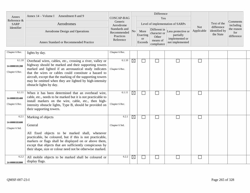
Annex
Reference &
SARP
Identifier
Annex 14 – Volume I Amendment 8 and 9 COSCAP-BAG
Generic
Aerodrome
Standards and
Recommended
Practices
Reference
Difference
Not
Applicable
Text of the
difference
identified by
the State
Comments
including
the reason
for
difference
No
Yes
Aerodromes Level of implementation of SARPs
Aerodrome Design and Operations
Annex Standard or Recommended Practice
More
Exacting
or
Exceeds
Different in
character or
Other
means of
compliance
Less protective or
partially
implemented or
not implemented
QMSF-007-23-I Page 265 of 328
Chapter 6 Rec. lights by day.
Chapter 6 Rec.
6.1.10
14-0000181200
Chapter 6 Rec.
Overhead wires, cables, etc., crossing a river, valley or
highway should be marked and their supporting towers
marked and lighted if an aeronautical study indicates
that the wires or cables could constitute a hazard to
aircraft, except that the marking of the supporting towers
may be omitted when they are lighted by high-intensity
obstacle lights by day.
6.1.10
Chapter 6 Rec.
6.1.11
14-0000181400
Chapter 6 Rec.
When it has been determined that an overhead wire,
cable, etc., needs to be marked but it is not practicable to
install markers on the wire, cable, etc., then high-
intensity obstacle lights, Type B, should be provided on
their supporting towers.
6.1.11
Chapter 6 Rec.
6.2.1
14-0000181600
Chapter 6 Std.
Marking of objects
General
All fixed objects to be marked shall, whenever
practicable, be coloured, but if this is not practicable,
markers or flags shall be displayed on or above them,
except that objects that are sufficiently conspicuous by
their shape, size or colour need not be otherwise marked.
6.2.1
Chapter 6 Std.
6.2.2
14-0000181800
All mobile objects to be marked shall be coloured or
display flags.
6.2.2
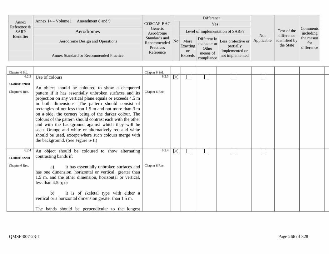
Annex
Reference &
SARP
Identifier
Annex 14 – Volume I Amendment 8 and 9 COSCAP-BAG
Generic
Aerodrome
Standards and
Recommended
Practices
Reference
Difference
Not
Applicable
Text of the
difference
identified by
the State
Comments
including
the reason
for
difference
No
Yes
Aerodromes Level of implementation of SARPs
Aerodrome Design and Operations
Annex Standard or Recommended Practice
More
Exacting
or
Exceeds
Different in
character or
Other
means of
compliance
Less protective or
partially
implemented or
not implemented
QMSF-007-23-I Page 266 of 328
Chapter 6 Std.
Chapter 6 Std.
6.2.3
14-0000182000
Chapter 6 Rec.
Use of colours
An object should be coloured to show a chequered
pattern if it has essentially unbroken surfaces and its
projection on any vertical plane equals or exceeds 4.5 m
in both dimensions. The pattern should consist of
rectangles of not less than 1.5 m and not more than 3 m
on a side, the corners being of the darker colour. The
colours of the pattern should contrast each with the other
and with the background against which they will be
seen. Orange and white or alternatively red and white
should be used, except where such colours merge with
the background. (See Figure 6-1.)
6.2.3
Chapter 6 Rec.
6.2.4
14-0000182200
Chapter 6 Rec.
An object should be coloured to show alternating
contrasting bands if:
a) it has essentially unbroken surfaces and
has one dimension, horizontal or vertical, greater than
1.5 m, and the other dimension, horizontal or vertical,
less than 4.5m; or
b) it is of skeletal type with either a
vertical or a horizontal dimension greater than 1.5 m.
The bands should be perpendicular to the longest
6.2.4
Chapter 6 Rec.
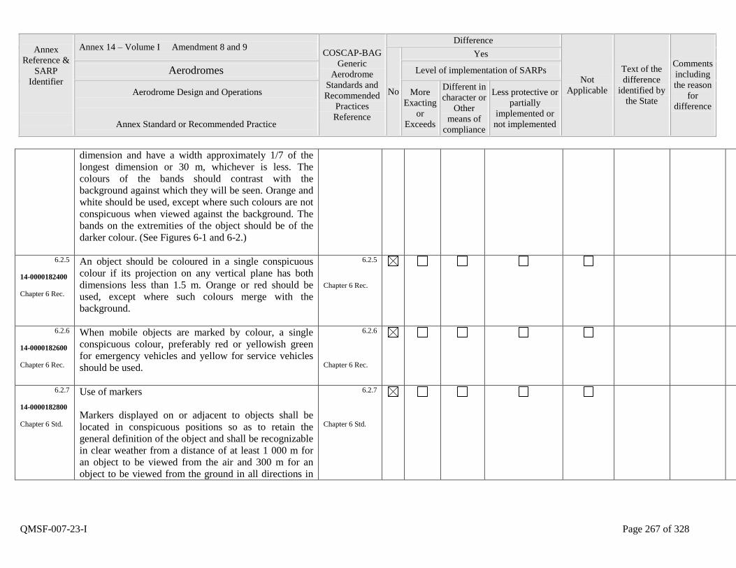
Annex
Reference &
SARP
Identifier
Annex 14 – Volume I Amendment 8 and 9 COSCAP-BAG
Generic
Aerodrome
Standards and
Recommended
Practices
Reference
Difference
Not
Applicable
Text of the
difference
identified by
the State
Comments
including
the reason
for
difference
No
Yes
Aerodromes Level of implementation of SARPs
Aerodrome Design and Operations
Annex Standard or Recommended Practice
More
Exacting
or
Exceeds
Different in
character or
Other
means of
compliance
Less protective or
partially
implemented or
not implemented
QMSF-007-23-I Page 267 of 328
dimension and have a width approximately 1/7 of the
longest dimension or 30 m, whichever is less. The
colours of the bands should contrast with the
background against which they will be seen. Orange and
white should be used, except where such colours are not
conspicuous when viewed against the background. The
bands on the extremities of the object should be of the
darker colour. (See Figures 6-1 and 6-2.)
6.2.5
14-0000182400
Chapter 6 Rec.
An object should be coloured in a single conspicuous
colour if its projection on any vertical plane has both
dimensions less than 1.5 m. Orange or red should be
used, except where such colours merge with the
background.
6.2.5
Chapter 6 Rec.
6.2.6
14-0000182600
Chapter 6 Rec.
When mobile objects are marked by colour, a single
conspicuous colour, preferably red or yellowish green
for emergency vehicles and yellow for service vehicles
should be used.
6.2.6
Chapter 6 Rec.
6.2.7
14-0000182800
Chapter 6 Std.
Use of markers
Markers displayed on or adjacent to objects shall be
located in conspicuous positions so as to retain the
general definition of the object and shall be recognizable
in clear weather from a distance of at least 1 000 m for
an object to be viewed from the air and 300 m for an
object to be viewed from the ground in all directions in
6.2.7
Chapter 6 Std.
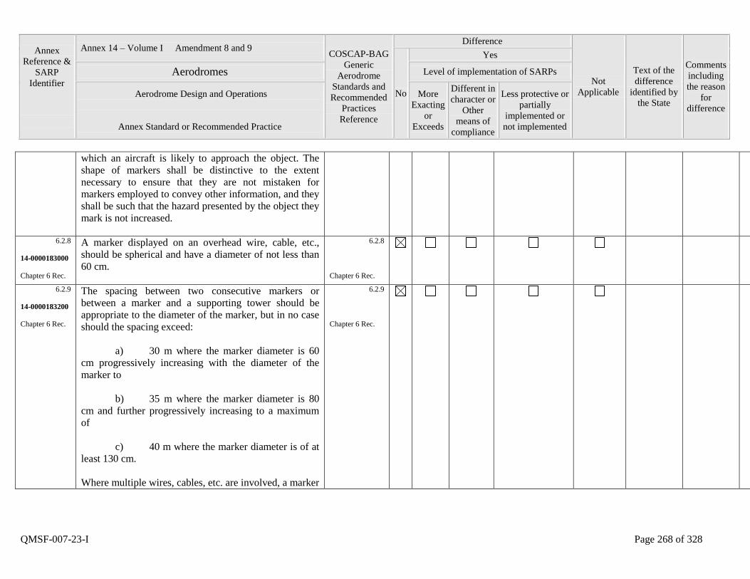
Annex
Reference &
SARP
Identifier
Annex 14 – Volume I Amendment 8 and 9 COSCAP-BAG
Generic
Aerodrome
Standards and
Recommended
Practices
Reference
Difference
Not
Applicable
Text of the
difference
identified by
the State
Comments
including
the reason
for
difference
No
Yes
Aerodromes Level of implementation of SARPs
Aerodrome Design and Operations
Annex Standard or Recommended Practice
More
Exacting
or
Exceeds
Different in
character or
Other
means of
compliance
Less protective or
partially
implemented or
not implemented
QMSF-007-23-I Page 268 of 328
which an aircraft is likely to approach the object. The
shape of markers shall be distinctive to the extent
necessary to ensure that they are not mistaken for
markers employed to convey other information, and they
shall be such that the hazard presented by the object they
mark is not increased.
6.2.8
14-0000183000
Chapter 6 Rec.
A marker displayed on an overhead wire, cable, etc.,
should be spherical and have a diameter of not less than
60 cm.
6.2.8
Chapter 6 Rec.
6.2.9
14-0000183200
Chapter 6 Rec.
The spacing between two consecutive markers or
between a marker and a supporting tower should be
appropriate to the diameter of the marker, but in no case
should the spacing exceed:
a) 30 m where the marker diameter is 60
cm progressively increasing with the diameter of the
marker to
b) 35 m where the marker diameter is 80
cm and further progressively increasing to a maximum
of
c) 40 m where the marker diameter is of at
least 130 cm.
Where multiple wires, cables, etc. are involved, a marker
6.2.9
Chapter 6 Rec.
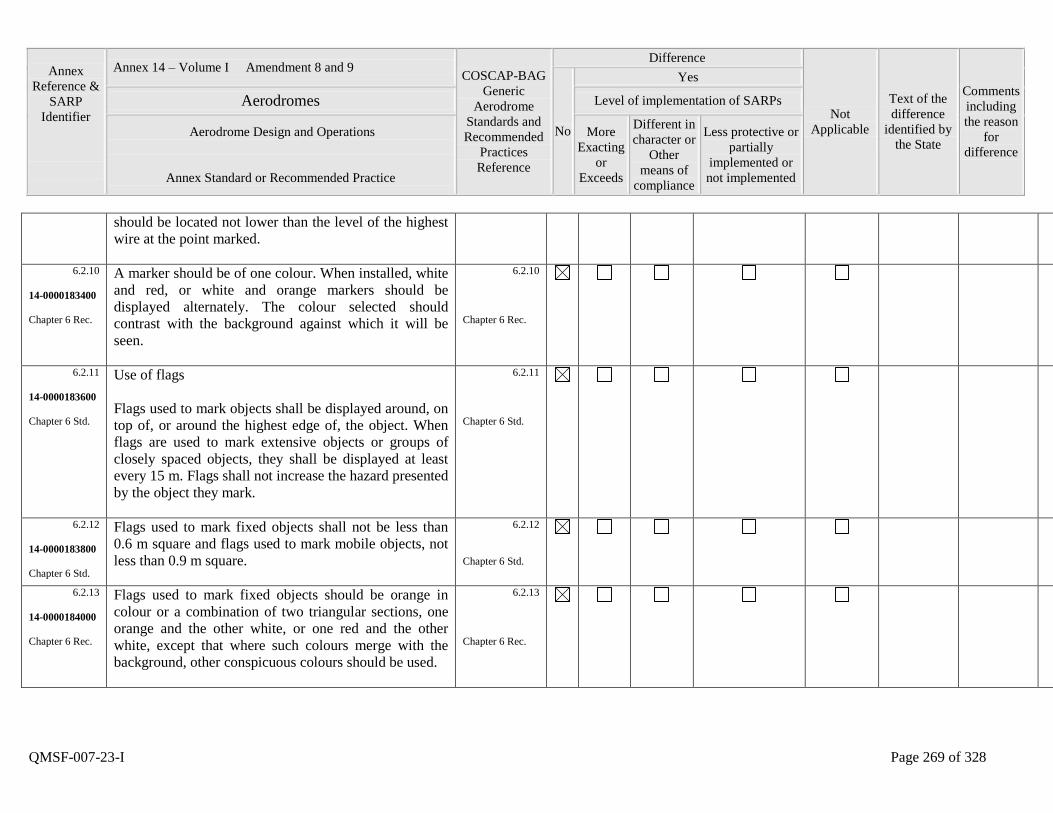
Annex
Reference &
SARP
Identifier
Annex 14 – Volume I Amendment 8 and 9 COSCAP-BAG
Generic
Aerodrome
Standards and
Recommended
Practices
Reference
Difference
Not
Applicable
Text of the
difference
identified by
the State
Comments
including
the reason
for
difference
No
Yes
Aerodromes Level of implementation of SARPs
Aerodrome Design and Operations
Annex Standard or Recommended Practice
More
Exacting
or
Exceeds
Different in
character or
Other
means of
compliance
Less protective or
partially
implemented or
not implemented
QMSF-007-23-I Page 269 of 328
should be located not lower than the level of the highest
wire at the point marked.
6.2.10
14-0000183400
Chapter 6 Rec.
A marker should be of one colour. When installed, white
and red, or white and orange markers should be
displayed alternately. The colour selected should
contrast with the background against which it will be
seen.
6.2.10
Chapter 6 Rec.
6.2.11
14-0000183600
Chapter 6 Std.
Use of flags
Flags used to mark objects shall be displayed around, on
top of, or around the highest edge of, the object. When
flags are used to mark extensive objects or groups of
closely spaced objects, they shall be displayed at least
every 15 m. Flags shall not increase the hazard presented
by the object they mark.
6.2.11
Chapter 6 Std.
6.2.12
14-0000183800
Chapter 6 Std.
Flags used to mark fixed objects shall not be less than
0.6 m square and flags used to mark mobile objects, not
less than 0.9 m square.
6.2.12
Chapter 6 Std.
6.2.13
14-0000184000
Chapter 6 Rec.
Flags used to mark fixed objects should be orange in
colour or a combination of two triangular sections, one
orange and the other white, or one red and the other
white, except that where such colours merge with the
background, other conspicuous colours should be used.
6.2.13
Chapter 6 Rec.
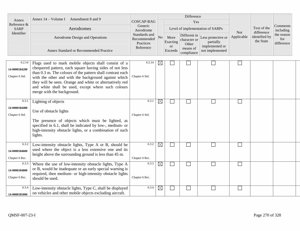
Annex
Reference &
SARP
Identifier
Annex 14 – Volume I Amendment 8 and 9 COSCAP-BAG
Generic
Aerodrome
Standards and
Recommended
Practices
Reference
Difference
Not
Applicable
Text of the
difference
identified by
the State
Comments
including
the reason
for
difference
No
Yes
Aerodromes Level of implementation of SARPs
Aerodrome Design and Operations
Annex Standard or Recommended Practice
More
Exacting
or
Exceeds
Different in
character or
Other
means of
compliance
Less protective or
partially
implemented or
not implemented
QMSF-007-23-I Page 270 of 328
6.2.14
14-0000184200
Chapter 6 Std.
Flags used to mark mobile objects shall consist of a
chequered pattern, each square having sides of not less
than 0.3 m. The colours of the pattern shall contrast each
with the other and with the background against which
they will be seen. Orange and white or alternatively red
and white shall be used, except where such colours
merge with the background.
6.2.14
Chapter 6 Std.
6.3.1
14-0000184400
Chapter 6 Std.
Lighting of objects
Use of obstacle lights
The presence of objects which must be lighted, as
specified in 6.1, shall be indicated by low-, medium- or
high-intensity obstacle lights, or a combination of such
lights.
6.3.1
Chapter 6 Std.
6.3.2
14-0000184600
Chapter 6 Rec.
Low-intensity obstacle lights, Type A or B, should be
used where the object is a less extensive one and its
height above the surrounding ground is less than 45 m.
6.3.2
Chapter 6 Rec.
6.3.3
14-0000184800
Chapter 6 Rec.
Where the use of low-intensity obstacle lights, Type A
or B, would be inadequate or an early special warning is
required, then medium- or high-intensity obstacle lights
should be used.
6.3.3
Chapter 6 Rec.
6.3.4
14-0000185000
Low-intensity obstacle lights, Type C, shall be displayed
on vehicles and other mobile objects excluding aircraft.
6.3.4
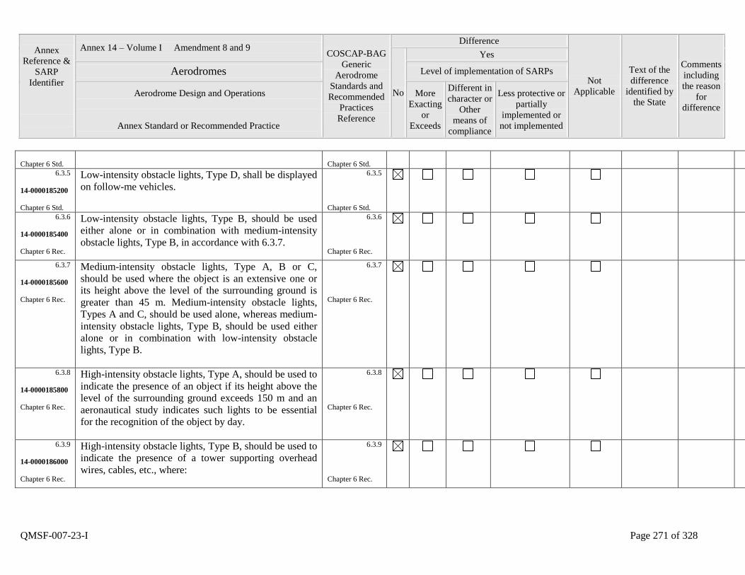
Annex
Reference &
SARP
Identifier
Annex 14 – Volume I Amendment 8 and 9 COSCAP-BAG
Generic
Aerodrome
Standards and
Recommended
Practices
Reference
Difference
Not
Applicable
Text of the
difference
identified by
the State
Comments
including
the reason
for
difference
No
Yes
Aerodromes Level of implementation of SARPs
Aerodrome Design and Operations
Annex Standard or Recommended Practice
More
Exacting
or
Exceeds
Different in
character or
Other
means of
compliance
Less protective or
partially
implemented or
not implemented
QMSF-007-23-I Page 271 of 328
Chapter 6 Std.
Chapter 6 Std.
6.3.5
14-0000185200
Chapter 6 Std.
Low-intensity obstacle lights, Type D, shall be displayed
on follow-me vehicles.
6.3.5
Chapter 6 Std.
6.3.6
14-0000185400
Chapter 6 Rec.
Low-intensity obstacle lights, Type B, should be used
either alone or in combination with medium-intensity
obstacle lights, Type B, in accordance with 6.3.7.
6.3.6
Chapter 6 Rec.
6.3.7
14-0000185600
Chapter 6 Rec.
Medium-intensity obstacle lights, Type A, B or C,
should be used where the object is an extensive one or
its height above the level of the surrounding ground is
greater than 45 m. Medium-intensity obstacle lights,
Types A and C, should be used alone, whereas medium-
intensity obstacle lights, Type B, should be used either
alone or in combination with low-intensity obstacle
lights, Type B.
6.3.7
Chapter 6 Rec.
6.3.8
14-0000185800
Chapter 6 Rec.
High-intensity obstacle lights, Type A, should be used to
indicate the presence of an object if its height above the
level of the surrounding ground exceeds 150 m and an
aeronautical study indicates such lights to be essential
for the recognition of the object by day.
6.3.8
Chapter 6 Rec.
6.3.9
14-0000186000
Chapter 6 Rec.
High-intensity obstacle lights, Type B, should be used to
indicate the presence of a tower supporting overhead
wires, cables, etc., where:
6.3.9
Chapter 6 Rec.
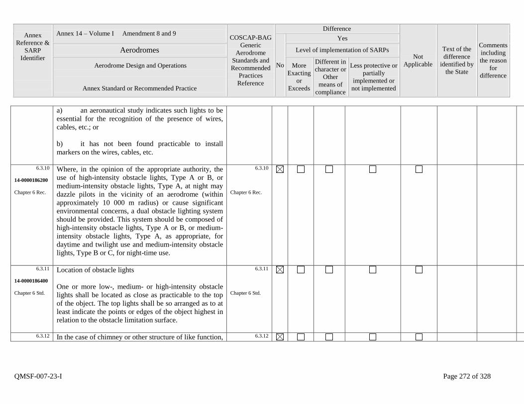
Annex
Reference &
SARP
Identifier
Annex 14 – Volume I Amendment 8 and 9 COSCAP-BAG
Generic
Aerodrome
Standards and
Recommended
Practices
Reference
Difference
Not
Applicable
Text of the
difference
identified by
the State
Comments
including
the reason
for
difference
No
Yes
Aerodromes Level of implementation of SARPs
Aerodrome Design and Operations
Annex Standard or Recommended Practice
More
Exacting
or
Exceeds
Different in
character or
Other
means of
compliance
Less protective or
partially
implemented or
not implemented
QMSF-007-23-I Page 272 of 328
a) an aeronautical study indicates such lights to be
essential for the recognition of the presence of wires,
cables, etc.; or
b) it has not been found practicable to install
markers on the wires, cables, etc.
6.3.10
14-0000186200
Chapter 6 Rec.
Where, in the opinion of the appropriate authority, the
use of high-intensity obstacle lights, Type A or B, or
medium-intensity obstacle lights, Type A, at night may
dazzle pilots in the vicinity of an aerodrome (within
approximately 10 000 m radius) or cause significant
environmental concerns, a dual obstacle lighting system
should be provided. This system should be composed of
high-intensity obstacle lights, Type A or B, or medium-
intensity obstacle lights, Type A, as appropriate, for
daytime and twilight use and medium-intensity obstacle
lights, Type B or C, for night-time use.
6.3.10
Chapter 6 Rec.
6.3.11
14-0000186400
Chapter 6 Std.
Location of obstacle lights
One or more low-, medium- or high-intensity obstacle
lights shall be located as close as practicable to the top
of the object. The top lights shall be so arranged as to at
least indicate the points or edges of the object highest in
relation to the obstacle limitation surface.
6.3.11
Chapter 6 Std.
6.3.12 In the case of chimney or other structure of like function, 6.3.12

Annex
Reference &
SARP
Identifier
Annex 14 – Volume I Amendment 8 and 9 COSCAP-BAG
Generic
Aerodrome
Standards and
Recommended
Practices
Reference
Difference
Not
Applicable
Text of the
difference
identified by
the State
Comments
including
the reason
for
difference
No
Yes
Aerodromes Level of implementation of SARPs
Aerodrome Design and Operations
Annex Standard or Recommended Practice
More
Exacting
or
Exceeds
Different in
character or
Other
means of
compliance
Less protective or
partially
implemented or
not implemented
QMSF-007-23-I Page 273 of 328
14-0000186600
Chapter 6 Rec.
the top lights should be placed sufficiently below the top
so as to minimize contamination by smoke etc. (see
Figures 6-2 and 6-3).
Chapter 6 Rec.
6.3.13
14-0000186800
Chapter 6 Std.
In the case of a tower or antenna structure indicated by
high-intensity obstacle lights by day with an
appurtenance, such as a rod or an antenna, greater than
12 m where it is not practicable to locate a high-intensity
obstacle light on the top of the appurtenance, such a light
shall be located at the highest practicable point and, if
practicable, a medium-intensity obstacle light, Type A,
mounted on the top.
6.3.13
Chapter 6 Std.
6.3.14
14-0000187000
Chapter 6 Std.
In the case of an extensive object or of a group of
closely spaced objects, top lights shall be displayed at
least on the points or edges of the objects highest in
relation to the obstacle limitation surface, so as to
indicate the general definition and the extent of the
objects. If two or more edges are of the same height, the
edge nearest the landing area shall be marked. Where
low-intensity lights are used, they shall be spaced at
longitudinal intervals not exceeding 45 m. Where
medium-intensity lights are used, they shall be spaced at
longitudinal intervals not exceeding 900 m.
6.3.14
Chapter 6 Std.
6.3.15
14-0000187200
When the obstacle limitation surface concerned is
sloping and the highest point above the obstacle
limitation surface is not the highest point of the object,
6.3.15
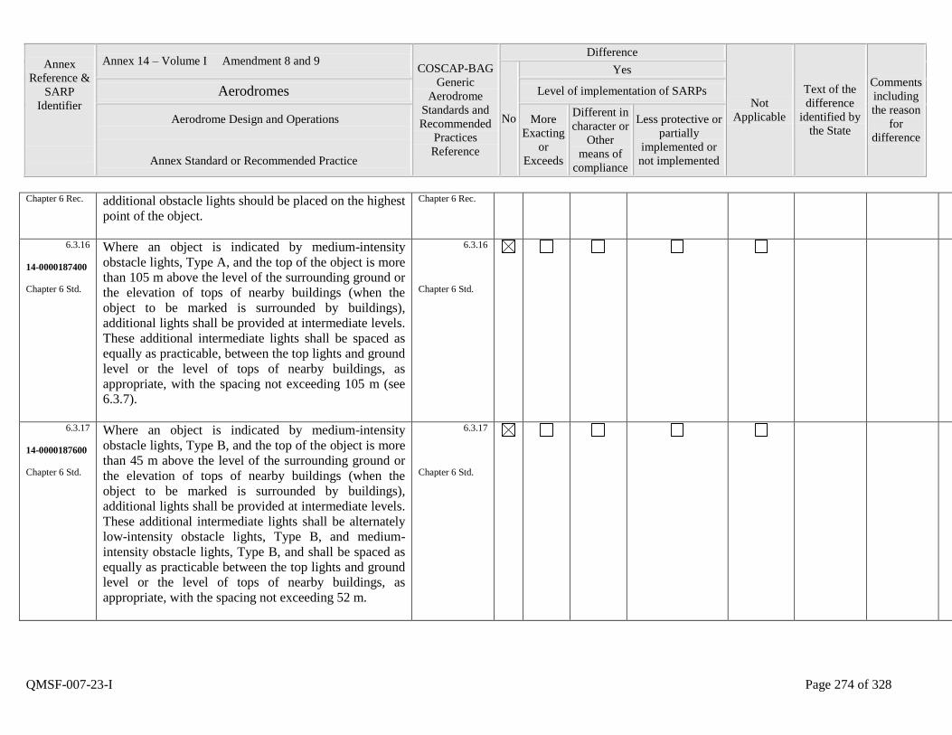
Annex
Reference &
SARP
Identifier
Annex 14 – Volume I Amendment 8 and 9 COSCAP-BAG
Generic
Aerodrome
Standards and
Recommended
Practices
Reference
Difference
Not
Applicable
Text of the
difference
identified by
the State
Comments
including
the reason
for
difference
No
Yes
Aerodromes Level of implementation of SARPs
Aerodrome Design and Operations
Annex Standard or Recommended Practice
More
Exacting
or
Exceeds
Different in
character or
Other
means of
compliance
Less protective or
partially
implemented or
not implemented
QMSF-007-23-I Page 274 of 328
Chapter 6 Rec. additional obstacle lights should be placed on the highest
point of the object.
Chapter 6 Rec.
6.3.16
14-0000187400
Chapter 6 Std.
Where an object is indicated by medium-intensity
obstacle lights, Type A, and the top of the object is more
than 105 m above the level of the surrounding ground or
the elevation of tops of nearby buildings (when the
object to be marked is surrounded by buildings),
additional lights shall be provided at intermediate levels.
These additional intermediate lights shall be spaced as
equally as practicable, between the top lights and ground
level or the level of tops of nearby buildings, as
appropriate, with the spacing not exceeding 105 m (see
6.3.7).
6.3.16
Chapter 6 Std.
6.3.17
14-0000187600
Chapter 6 Std.
Where an object is indicated by medium-intensity
obstacle lights, Type B, and the top of the object is more
than 45 m above the level of the surrounding ground or
the elevation of tops of nearby buildings (when the
object to be marked is surrounded by buildings),
additional lights shall be provided at intermediate levels.
These additional intermediate lights shall be alternately
low-intensity obstacle lights, Type B, and medium-
intensity obstacle lights, Type B, and shall be spaced as
equally as practicable between the top lights and ground
level or the level of tops of nearby buildings, as
appropriate, with the spacing not exceeding 52 m.
6.3.17
Chapter 6 Std.
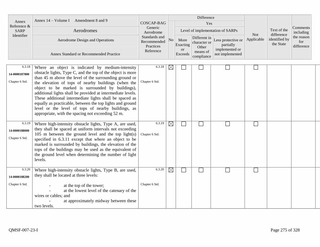
Annex
Reference &
SARP
Identifier
Annex 14 – Volume I Amendment 8 and 9 COSCAP-BAG
Generic
Aerodrome
Standards and
Recommended
Practices
Reference
Difference
Not
Applicable
Text of the
difference
identified by
the State
Comments
including
the reason
for
difference
No
Yes
Aerodromes Level of implementation of SARPs
Aerodrome Design and Operations
Annex Standard or Recommended Practice
More
Exacting
or
Exceeds
Different in
character or
Other
means of
compliance
Less protective or
partially
implemented or
not implemented
QMSF-007-23-I Page 275 of 328
6.3.18
14-0000187800
Chapter 6 Std.
Where an object is indicated by medium-intensity
obstacle lights, Type C, and the top of the object is more
than 45 m above the level of the surrounding ground or
the elevation of tops of nearby buildings (when the
object to be marked is surrounded by buildings),
additional lights shall be provided at intermediate levels.
These additional intermediate lights shall be spaced as
equally as practicable, between the top lights and ground
level or the level of tops of nearby buildings, as
appropriate, with the spacing not exceeding 52 m.
6.3.18
Chapter 6 Std.
6.3.19
14-0000188000
Chapter 6 Std.
Where high-intensity obstacle lights, Type A, are used,
they shall be spaced at uniform intervals not exceeding
105 m between the ground level and the top light(s)
specified in 6.3.11 except that where an object to be
marked is surrounded by buildings, the elevation of the
tops of the buildings may be used as the equivalent of
the ground level when determining the number of light
levels.
6.3.19
Chapter 6 Std.
6.3.20
14-0000188200
Chapter 6 Std.
Where high-intensity obstacle lights, Type B, are used,
they shall be located at three levels:
- at the top of the tower;
- at the lowest level of the catenary of the
wires or cables; and
- at approximately midway between these
two levels.
6.3.20
Chapter 6 Std.

Annex
Reference &
SARP
Identifier
Annex 14 – Volume I Amendment 8 and 9 COSCAP-BAG
Generic
Aerodrome
Standards and
Recommended
Practices
Reference
Difference
Not
Applicable
Text of the
difference
identified by
the State
Comments
including
the reason
for
difference
No
Yes
Aerodromes Level of implementation of SARPs
Aerodrome Design and Operations
Annex Standard or Recommended Practice
More
Exacting
or
Exceeds
Different in
character or
Other
means of
compliance
Less protective or
partially
implemented or
not implemented
QMSF-007-23-I Page 276 of 328
6.3.21
14-0000188400
Chapter 6 Rec.
The installation setting angles for high-intensity obstacle
lights, Types A and B, should be in accordance with
Table 6-2.
6.3.21
Chapter 6 Rec.
6.3.22
14-0000188600
Chapter 6 Std.
The number and arrangement of low-, medium- or high-
intensity obstacle lights at each level to be marked shall
be such that the object is indicated from every angle in
azimuth. Where a light is shielded in any direction by
another part of the object, or by an adjacent object,
additional lights shall be provided on that object in such
a way as to retain the general definition of the object to
be lighted. If the shielded light does not contribute to the
definition of the object to be lighted, it may be omitted.
6.3.22
Chapter 6 Std.
6.3.23
14-0000188800
Chapter 6 Std.
Low-intensity obstacle light - Characteristics
Low-intensity obstacle lights on fixed objects, Types A
and B, shall be fixed-red lights.
6.3.23
Chapter 6 Std.
6.3.24
14-0000189000
Chapter 6 Std.
Low-intensity obstacle lights, Types A and B, shall be in
accordance with the specifications in Table 6-3.
6.3.24
Chapter 6 Std.
6.3.25
14-0000189200
Chapter 6 Std.
Low-intensity obstacle lights, Type C, displayed on
vehicles associated with emergency or security shall be
flashing-blue and those displayed on other vehicles shall
be flashing-yellow.
6.3.25
Chapter 6 Std.
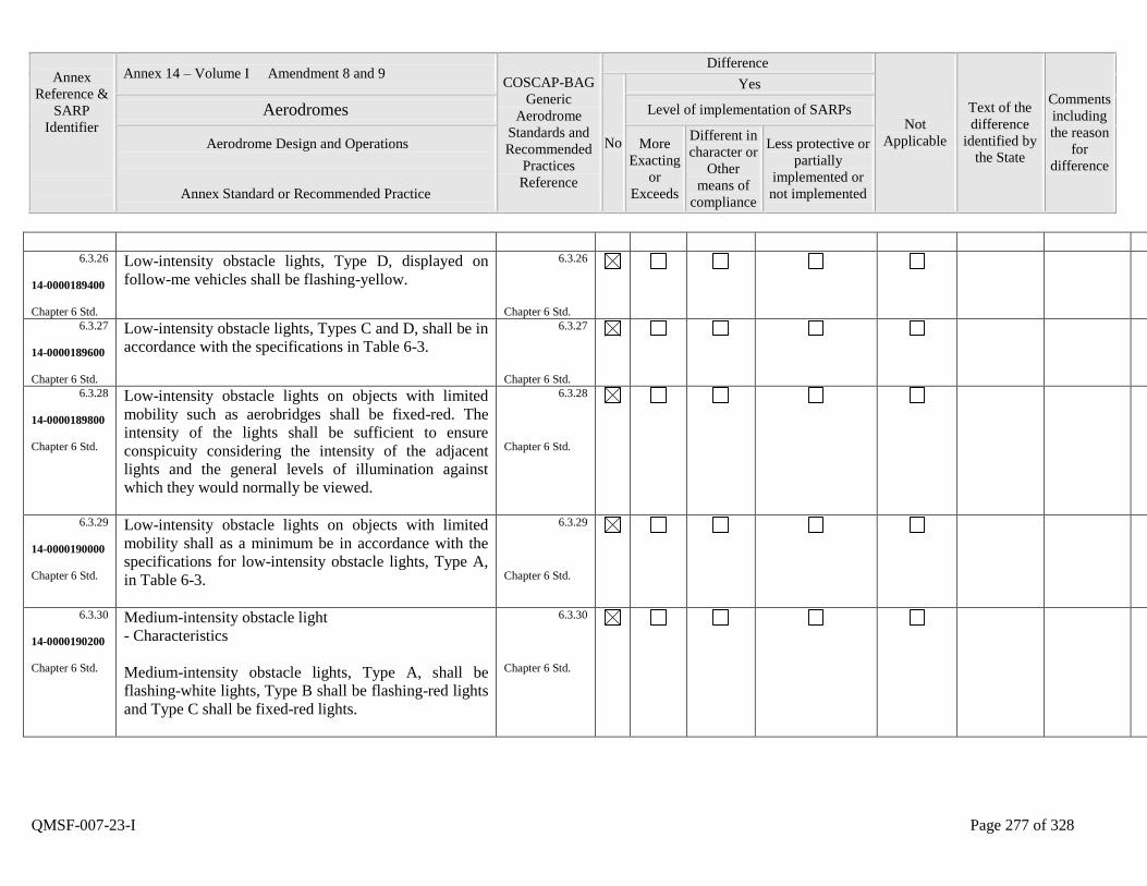
Annex
Reference &
SARP
Identifier
Annex 14 – Volume I Amendment 8 and 9 COSCAP-BAG
Generic
Aerodrome
Standards and
Recommended
Practices
Reference
Difference
Not
Applicable
Text of the
difference
identified by
the State
Comments
including
the reason
for
difference
No
Yes
Aerodromes Level of implementation of SARPs
Aerodrome Design and Operations
Annex Standard or Recommended Practice
More
Exacting
or
Exceeds
Different in
character or
Other
means of
compliance
Less protective or
partially
implemented or
not implemented
QMSF-007-23-I Page 277 of 328
6.3.26
14-0000189400
Chapter 6 Std.
Low-intensity obstacle lights, Type D, displayed on
follow-me vehicles shall be flashing-yellow.
6.3.26
Chapter 6 Std.
6.3.27
14-0000189600
Chapter 6 Std.
Low-intensity obstacle lights, Types C and D, shall be in
accordance with the specifications in Table 6-3.
6.3.27
Chapter 6 Std.
6.3.28
14-0000189800
Chapter 6 Std.
Low-intensity obstacle lights on objects with limited
mobility such as aerobridges shall be fixed-red. The
intensity of the lights shall be sufficient to ensure
conspicuity considering the intensity of the adjacent
lights and the general levels of illumination against
which they would normally be viewed.
6.3.28
Chapter 6 Std.
6.3.29
14-0000190000
Chapter 6 Std.
Low-intensity obstacle lights on objects with limited
mobility shall as a minimum be in accordance with the
specifications for low-intensity obstacle lights, Type A,
in Table 6-3.
6.3.29
Chapter 6 Std.
6.3.30
14-0000190200
Chapter 6 Std.
Medium-intensity obstacle light
- Characteristics
Medium-intensity obstacle lights, Type A, shall be
flashing-white lights, Type B shall be flashing-red lights
and Type C shall be fixed-red lights.
6.3.30
Chapter 6 Std.
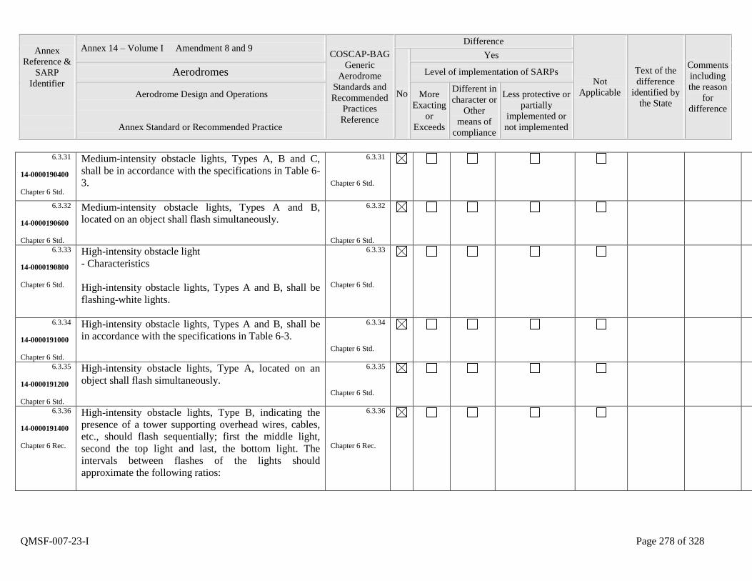
Annex
Reference &
SARP
Identifier
Annex 14 – Volume I Amendment 8 and 9 COSCAP-BAG
Generic
Aerodrome
Standards and
Recommended
Practices
Reference
Difference
Not
Applicable
Text of the
difference
identified by
the State
Comments
including
the reason
for
difference
No
Yes
Aerodromes Level of implementation of SARPs
Aerodrome Design and Operations
Annex Standard or Recommended Practice
More
Exacting
or
Exceeds
Different in
character or
Other
means of
compliance
Less protective or
partially
implemented or
not implemented
QMSF-007-23-I Page 278 of 328
6.3.31
14-0000190400
Chapter 6 Std.
Medium-intensity obstacle lights, Types A, B and C,
shall be in accordance with the specifications in Table 6-
3.
6.3.31
Chapter 6 Std.
6.3.32
14-0000190600
Chapter 6 Std.
Medium-intensity obstacle lights, Types A and B,
located on an object shall flash simultaneously.
6.3.32
Chapter 6 Std.
6.3.33
14-0000190800
Chapter 6 Std.
High-intensity obstacle light
- Characteristics
High-intensity obstacle lights, Types A and B, shall be
flashing-white lights.
6.3.33
Chapter 6 Std.
6.3.34
14-0000191000
Chapter 6 Std.
High-intensity obstacle lights, Types A and B, shall be
in accordance with the specifications in Table 6-3.
6.3.34
Chapter 6 Std.
6.3.35
14-0000191200
Chapter 6 Std.
High-intensity obstacle lights, Type A, located on an
object shall flash simultaneously.
6.3.35
Chapter 6 Std.
6.3.36
14-0000191400
Chapter 6 Rec.
High-intensity obstacle lights, Type B, indicating the
presence of a tower supporting overhead wires, cables,
etc., should flash sequentially; first the middle light,
second the top light and last, the bottom light. The
intervals between flashes of the lights should
approximate the following ratios:
6.3.36
Chapter 6 Rec.
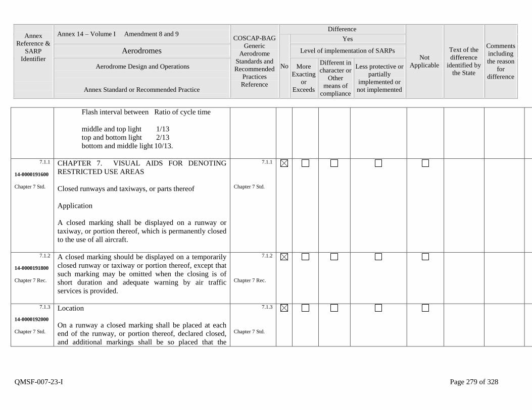
Annex
Reference &
SARP
Identifier
Annex 14 – Volume I Amendment 8 and 9 COSCAP-BAG
Generic
Aerodrome
Standards and
Recommended
Practices
Reference
Difference
Not
Applicable
Text of the
difference
identified by
the State
Comments
including
the reason
for
difference
No
Yes
Aerodromes Level of implementation of SARPs
Aerodrome Design and Operations
Annex Standard or Recommended Practice
More
Exacting
or
Exceeds
Different in
character or
Other
means of
compliance
Less protective or
partially
implemented or
not implemented
QMSF-007-23-I Page 279 of 328
Flash interval between Ratio of cycle time
middle and top light 1/13
top and bottom light 2/13
bottom and middle light 10/13.
7.1.1
14-0000191600
Chapter 7 Std.
CHAPTER 7. VISUAL AIDS FOR DENOTING
RESTRICTED USE AREAS
Closed runways and taxiways, or parts thereof
Application
A closed marking shall be displayed on a runway or
taxiway, or portion thereof, which is permanently closed
to the use of all aircraft.
7.1.1
Chapter 7 Std.
7.1.2
14-0000191800
Chapter 7 Rec.
A closed marking should be displayed on a temporarily
closed runway or taxiway or portion thereof, except that
such marking may be omitted when the closing is of
short duration and adequate warning by air traffic
services is provided.
7.1.2
Chapter 7 Rec.
7.1.3
14-0000192000
Chapter 7 Std.
Location
On a runway a closed marking shall be placed at each
end of the runway, or portion thereof, declared closed,
and additional markings shall be so placed that the
7.1.3
Chapter 7 Std.
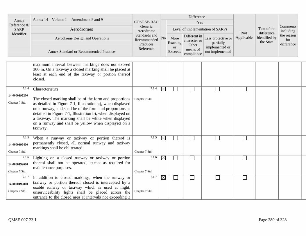
Annex
Reference &
SARP
Identifier
Annex 14 – Volume I Amendment 8 and 9 COSCAP-BAG
Generic
Aerodrome
Standards and
Recommended
Practices
Reference
Difference
Not
Applicable
Text of the
difference
identified by
the State
Comments
including
the reason
for
difference
No
Yes
Aerodromes Level of implementation of SARPs
Aerodrome Design and Operations
Annex Standard or Recommended Practice
More
Exacting
or
Exceeds
Different in
character or
Other
means of
compliance
Less protective or
partially
implemented or
not implemented
QMSF-007-23-I Page 280 of 328
maximum interval between markings does not exceed
300 m. On a taxiway a closed marking shall be placed at
least at each end of the taxiway or portion thereof
closed.
7.1.4
14-0000192200
Chapter 7 Std.
Characteristics
The closed marking shall be of the form and proportions
as detailed in Figure 7-1, Illustration a), when displayed
on a runway, and shall be of the form and proportions as
detailed in Figure 7-1, Illustration b), when displayed on
a taxiway. The marking shall be white when displayed
on a runway and shall be yellow when displayed on a
taxiway.
7.1.4
Chapter 7 Std.
7.1.5
14-0000192400
Chapter 7 Std.
When a runway or taxiway or portion thereof is
permanently closed, all normal runway and taxiway
markings shall be obliterated.
7.1.5
Chapter 7 Std.
7.1.6
14-0000192600
Chapter 7 Std.
Lighting on a closed runway or taxiway or portion
thereof shall not be operated, except as required for
maintenance purposes.
7.1.6
Chapter 7 Std.
7.1.7
14-0000192800
Chapter 7 Std.
In addition to closed markings, when the runway or
taxiway or portion thereof closed is intercepted by a
usable runway or taxiway which is used at night,
unserviceability lights shall be placed across the
entrance to the closed area at intervals not exceeding 3
7.1.7
Chapter 7 Std.
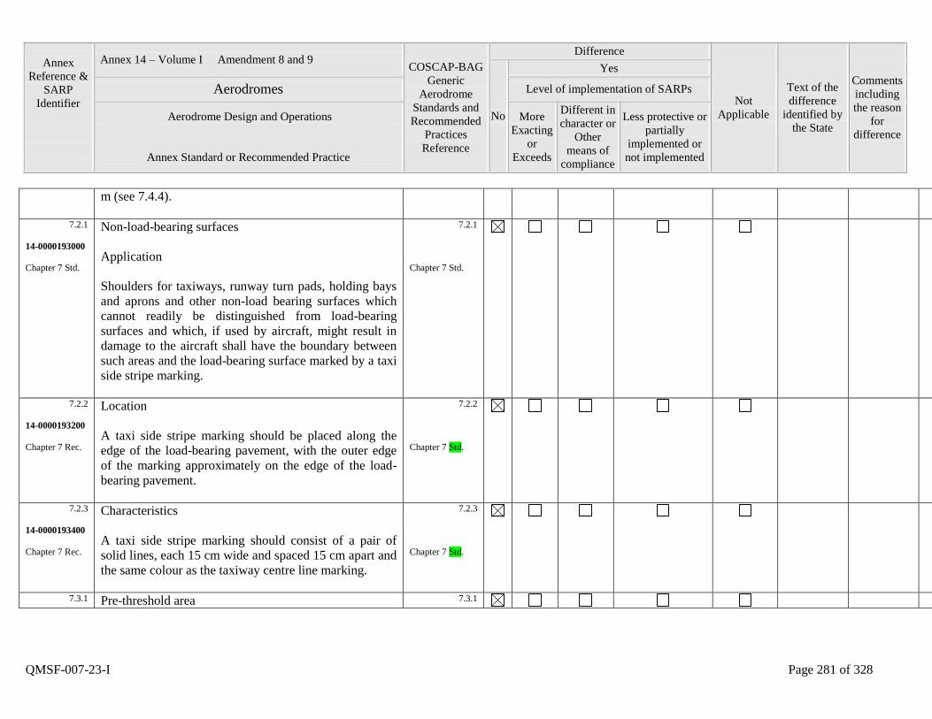
Annex
Reference &
SARP
Identifier
Annex 14 – Volume I Amendment 8 and 9 COSCAP-BAG
Generic
Aerodrome
Standards and
Recommended
Practices
Reference
Difference
Not
Applicable
Text of the
difference
identified by
the State
Comments
including
the reason
for
difference
No
Yes
Aerodromes Level of implementation of SARPs
Aerodrome Design and Operations
Annex Standard or Recommended Practice
More
Exacting
or
Exceeds
Different in
character or
Other
means of
compliance
Less protective or
partially
implemented or
not implemented
QMSF-007-23-I Page 281 of 328
m (see 7.4.4).
7.2.1
14-0000193000
Chapter 7 Std.
Non-load-bearing surfaces
Application
Shoulders for taxiways, runway turn pads, holding bays
and aprons and other non-load bearing surfaces which
cannot readily be distinguished from load-bearing
surfaces and which, if used by aircraft, might result in
damage to the aircraft shall have the boundary between
such areas and the load-bearing surface marked by a taxi
side stripe marking.
7.2.1
Chapter 7 Std.
7.2.2
14-0000193200
Chapter 7 Rec.
Location
A taxi side stripe marking should be placed along the
edge of the load-bearing pavement, with the outer edge
of the marking approximately on the edge of the load-
bearing pavement.
7.2.2
Chapter 7 Std.
7.2.3
14-0000193400
Chapter 7 Rec.
Characteristics
A taxi side stripe marking should consist of a pair of
solid lines, each 15 cm wide and spaced 15 cm apart and
the same colour as the taxiway centre line marking.
7.2.3
Chapter 7 Std.
7.3.1 Pre-threshold area 7.3.1
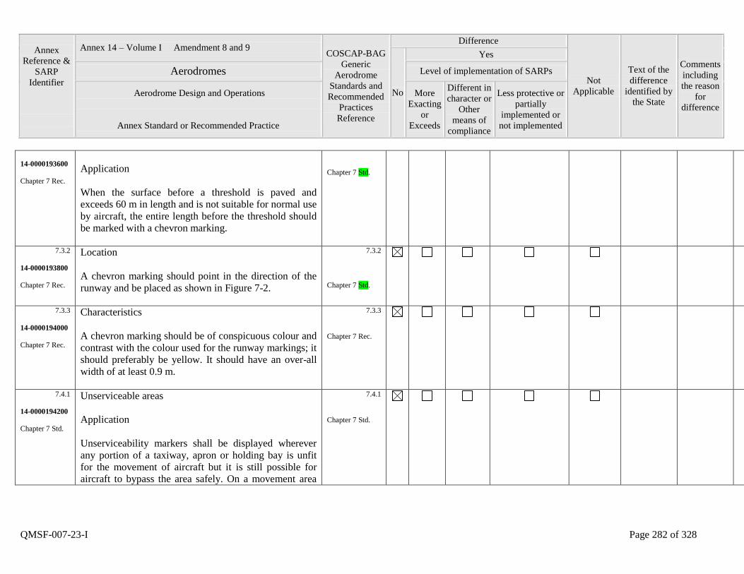
Annex
Reference &
SARP
Identifier
Annex 14 – Volume I Amendment 8 and 9 COSCAP-BAG
Generic
Aerodrome
Standards and
Recommended
Practices
Reference
Difference
Not
Applicable
Text of the
difference
identified by
the State
Comments
including
the reason
for
difference
No
Yes
Aerodromes Level of implementation of SARPs
Aerodrome Design and Operations
Annex Standard or Recommended Practice
More
Exacting
or
Exceeds
Different in
character or
Other
means of
compliance
Less protective or
partially
implemented or
not implemented
QMSF-007-23-I Page 282 of 328
14-0000193600
Chapter 7 Rec.
Application
When the surface before a threshold is paved and
exceeds 60 m in length and is not suitable for normal use
by aircraft, the entire length before the threshold should
be marked with a chevron marking.
Chapter 7 Std.
7.3.2
14-0000193800
Chapter 7 Rec.
Location
A chevron marking should point in the direction of the
runway and be placed as shown in Figure 7-2.
7.3.2
Chapter 7 Std.
7.3.3
14-0000194000
Chapter 7 Rec.
Characteristics
A chevron marking should be of conspicuous colour and
contrast with the colour used for the runway markings; it
should preferably be yellow. It should have an over-all
width of at least 0.9 m.
7.3.3
Chapter 7 Rec.
7.4.1
14-0000194200
Chapter 7 Std.
Unserviceable areas
Application
Unserviceability markers shall be displayed wherever
any portion of a taxiway, apron or holding bay is unfit
for the movement of aircraft but it is still possible for
aircraft to bypass the area safely. On a movement area
7.4.1
Chapter 7 Std.
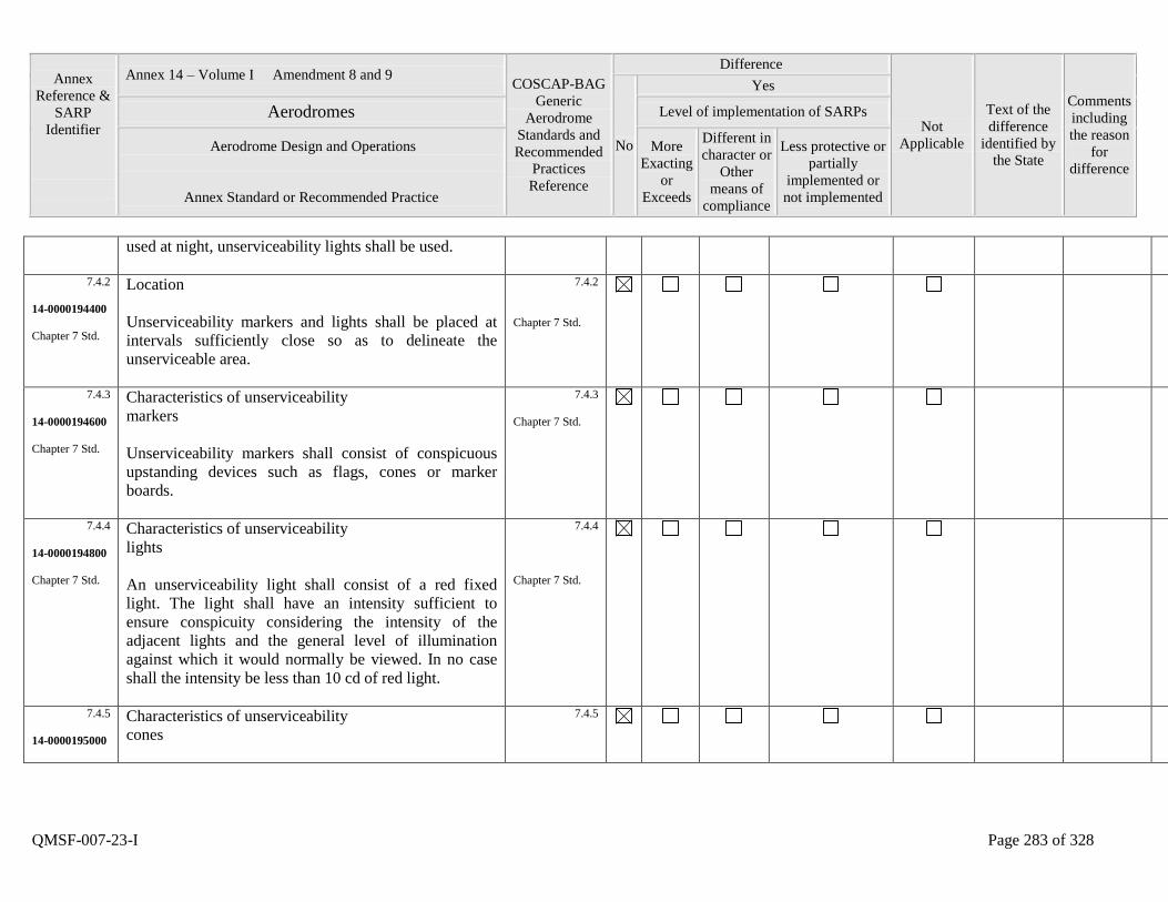
Annex
Reference &
SARP
Identifier
Annex 14 – Volume I Amendment 8 and 9 COSCAP-BAG
Generic
Aerodrome
Standards and
Recommended
Practices
Reference
Difference
Not
Applicable
Text of the
difference
identified by
the State
Comments
including
the reason
for
difference
No
Yes
Aerodromes Level of implementation of SARPs
Aerodrome Design and Operations
Annex Standard or Recommended Practice
More
Exacting
or
Exceeds
Different in
character or
Other
means of
compliance
Less protective or
partially
implemented or
not implemented
QMSF-007-23-I Page 283 of 328
used at night, unserviceability lights shall be used.
7.4.2
14-0000194400
Chapter 7 Std.
Location
Unserviceability markers and lights shall be placed at
intervals sufficiently close so as to delineate the
unserviceable area.
7.4.2
Chapter 7 Std.
7.4.3
14-0000194600
Chapter 7 Std.
Characteristics of unserviceability
markers
Unserviceability markers shall consist of conspicuous
upstanding devices such as flags, cones or marker
boards.
7.4.3
Chapter 7 Std.
7.4.4
14-0000194800
Chapter 7 Std.
Characteristics of unserviceability
lights
An unserviceability light shall consist of a red fixed
light. The light shall have an intensity sufficient to
ensure conspicuity considering the intensity of the
adjacent lights and the general level of illumination
against which it would normally be viewed. In no case
shall the intensity be less than 10 cd of red light.
7.4.4
Chapter 7 Std.
7.4.5
14-0000195000
Characteristics of unserviceability
cones
7.4.5

Annex
Reference &
SARP
Identifier
Annex 14 – Volume I Amendment 8 and 9 COSCAP-BAG
Generic
Aerodrome
Standards and
Recommended
Practices
Reference
Difference
Not
Applicable
Text of the
difference
identified by
the State
Comments
including
the reason
for
difference
No
Yes
Aerodromes Level of implementation of SARPs
Aerodrome Design and Operations
Annex Standard or Recommended Practice
More
Exacting
or
Exceeds
Different in
character or
Other
means of
compliance
Less protective or
partially
implemented or
not implemented
QMSF-007-23-I Page 284 of 328
Chapter 7 Rec. An unserviceability cone should be at least 0.5 m in
height and red, orange or yellow or any one of these
colours in combination with white.
Chapter 7 Rec.
7.4.6
14-0000195200
Chapter 7 Rec.
Characteristics of unserviceability
flags
An unserviceability flag should be at least 0.5 m square
and red, orange or yellow or any one of these colours in
combination with white.
7.4.6
Chapter 7 Rec.
7.4.7
14-0000195400
Chapter 7 Rec.
Characteristics of unserviceability
marker boards
An unserviceability marker board should be at least 0.5
m in height and 0.9 m in length, with alternate red and
white or orange and white vertical stripes.
7.4.7
Chapter 7 Rec.
8.1.1
14-0000195600
Chapter 8 Std.
CHAPTER 8. EQUIPMENT AND INSTALLATIONS
Secondary power supply
Adequate primary power supply shall be available at
aerodromes for the safe functioning of air navigation
facilities.
8.1.1
Chapter 8 Std.
8.1.2
14-0000195800
The design and provision of electrical power systems for
aerodrome visual and radio navigation aids shall be such
8.1.2
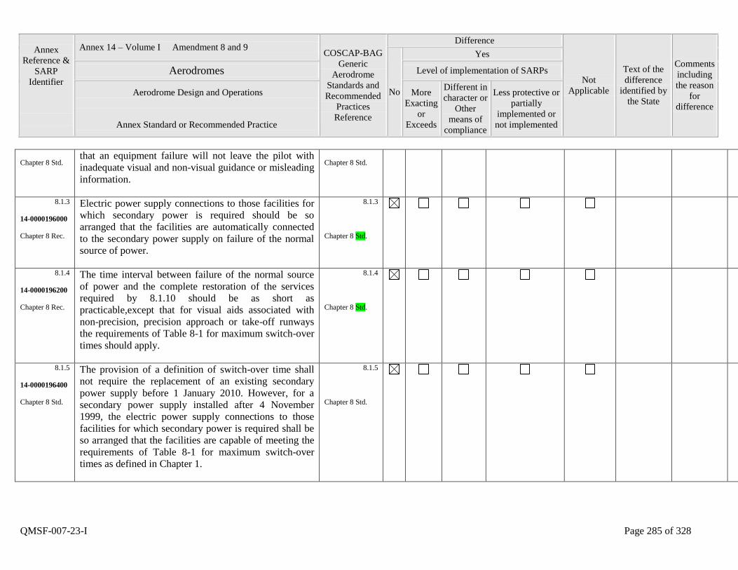
Annex
Reference &
SARP
Identifier
Annex 14 – Volume I Amendment 8 and 9 COSCAP-BAG
Generic
Aerodrome
Standards and
Recommended
Practices
Reference
Difference
Not
Applicable
Text of the
difference
identified by
the State
Comments
including
the reason
for
difference
No
Yes
Aerodromes Level of implementation of SARPs
Aerodrome Design and Operations
Annex Standard or Recommended Practice
More
Exacting
or
Exceeds
Different in
character or
Other
means of
compliance
Less protective or
partially
implemented or
not implemented
QMSF-007-23-I Page 285 of 328
Chapter 8 Std. that an equipment failure will not leave the pilot with
inadequate visual and non-visual guidance or misleading
information.
Chapter 8 Std.
8.1.3
14-0000196000
Chapter 8 Rec.
Electric power supply connections to those facilities for
which secondary power is required should be so
arranged that the facilities are automatically connected
to the secondary power supply on failure of the normal
source of power.
8.1.3
Chapter 8 Std.
8.1.4
14-0000196200
Chapter 8 Rec.
The time interval between failure of the normal source
of power and the complete restoration of the services
required by 8.1.10 should be as short as
practicable,except that for visual aids associated with
non-precision, precision approach or take-off runways
the requirements of Table 8-1 for maximum switch-over
times should apply.
8.1.4
Chapter 8 Std.
8.1.5
14-0000196400
Chapter 8 Std.
The provision of a definition of switch-over time shall
not require the replacement of an existing secondary
power supply before 1 January 2010. However, for a
secondary power supply installed after 4 November
1999, the electric power supply connections to those
facilities for which secondary power is required shall be
so arranged that the facilities are capable of meeting the
requirements of Table 8-1 for maximum switch-over
times as defined in Chapter 1.
8.1.5
Chapter 8 Std.
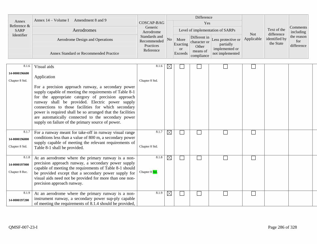
Annex
Reference &
SARP
Identifier
Annex 14 – Volume I Amendment 8 and 9 COSCAP-BAG
Generic
Aerodrome
Standards and
Recommended
Practices
Reference
Difference
Not
Applicable
Text of the
difference
identified by
the State
Comments
including
the reason
for
difference
No
Yes
Aerodromes Level of implementation of SARPs
Aerodrome Design and Operations
Annex Standard or Recommended Practice
More
Exacting
or
Exceeds
Different in
character or
Other
means of
compliance
Less protective or
partially
implemented or
not implemented
QMSF-007-23-I Page 286 of 328
8.1.6
14-0000196600
Chapter 8 Std.
Visual aids
Application
For a precision approach runway, a secondary power
supply capable of meeting the requirements of Table 8-1
for the appropriate category of precision approach
runway shall be provided. Electric power supply
connections to those facilities for which secondary
power is required shall be so arranged that the facilities
are automatically connected to the secondary power
supply on failure of the primary source of power.
8.1.6
Chapter 8 Std.
8.1.7
14-0000196800
Chapter 8 Std.
For a runway meant for take-off in runway visual range
conditions less than a value of 800 m, a secondary power
supply capable of meeting the relevant requirements of
Table 8-1 shall be provided.
8.1.7
Chapter 8 Std.
8.1.8
14-0000197000
Chapter 8 Rec.
At an aerodrome where the primary runway is a non-
precision approach runway, a secondary power supply
capable of meeting the requirements of Table 8-1 should
be provided except that a secondary power supply for
visual aids need not be provided for more than one non-
precision approach runway.
8.1.8
Chapter 8 Std.
8.1.9
14-0000197200
At an aerodrome where the primary runway is a non-
instrument runway, a secondary power supply capable
of meeting the requirements of 8.1.4 should be provided,
8.1.9
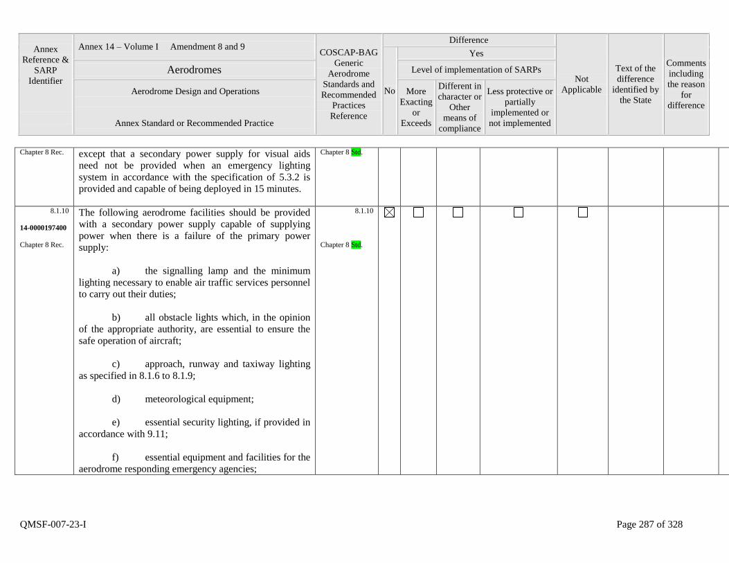
Annex
Reference &
SARP
Identifier
Annex 14 – Volume I Amendment 8 and 9 COSCAP-BAG
Generic
Aerodrome
Standards and
Recommended
Practices
Reference
Difference
Not
Applicable
Text of the
difference
identified by
the State
Comments
including
the reason
for
difference
No
Yes
Aerodromes Level of implementation of SARPs
Aerodrome Design and Operations
Annex Standard or Recommended Practice
More
Exacting
or
Exceeds
Different in
character or
Other
means of
compliance
Less protective or
partially
implemented or
not implemented
QMSF-007-23-I Page 287 of 328
Chapter 8 Rec. except that a secondary power supply for visual aids
need not be provided when an emergency lighting
system in accordance with the specification of 5.3.2 is
provided and capable of being deployed in 15 minutes.
Chapter 8 Std.
8.1.10
14-0000197400
Chapter 8 Rec.
The following aerodrome facilities should be provided
with a secondary power supply capable of supplying
power when there is a failure of the primary power
supply:
a) the signalling lamp and the minimum
lighting necessary to enable air traffic services personnel
to carry out their duties;
b) all obstacle lights which, in the opinion
of the appropriate authority, are essential to ensure the
safe operation of aircraft;
c) approach, runway and taxiway lighting
as specified in 8.1.6 to 8.1.9;
d) meteorological equipment;
e) essential security lighting, if provided in
accordance with 9.11;
f) essential equipment and facilities for the
aerodrome responding emergency agencies;
8.1.10
Chapter 8 Std.
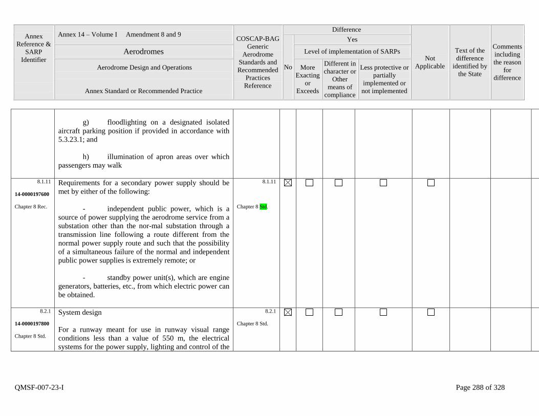
Annex
Reference &
SARP
Identifier
Annex 14 – Volume I Amendment 8 and 9 COSCAP-BAG
Generic
Aerodrome
Standards and
Recommended
Practices
Reference
Difference
Not
Applicable
Text of the
difference
identified by
the State
Comments
including
the reason
for
difference
No
Yes
Aerodromes Level of implementation of SARPs
Aerodrome Design and Operations
Annex Standard or Recommended Practice
More
Exacting
or
Exceeds
Different in
character or
Other
means of
compliance
Less protective or
partially
implemented or
not implemented
QMSF-007-23-I Page 288 of 328
g) floodlighting on a designated isolated
aircraft parking position if provided in accordance with
5.3.23.1; and
h) illumination of apron areas over which
passengers may walk
8.1.11
14-0000197600
Chapter 8 Rec.
Requirements for a secondary power supply should be
met by either of the following:
- independent public power, which is a
source of power supplying the aerodrome service from a
substation other than the normal substation through a
transmission line following a route different from the
normal power supply route and such that the possibility
of a simultaneous failure of the normal and independent
public power supplies is extremely remote; or
- standby power unit(s), which are engine
generators, batteries, etc., from which electric power can
be obtained.
8.1.11
Chapter 8 Std.
8.2.1
14-0000197800
Chapter 8 Std.
System design
For a runway meant for use in runway visual range
conditions less than a value of 550 m, the electrical
systems for the power supply, lighting and control of the
8.2.1
Chapter 8 Std.

Annex
Reference &
SARP
Identifier
Annex 14 – Volume I Amendment 8 and 9 COSCAP-BAG
Generic
Aerodrome
Standards and
Recommended
Practices
Reference
Difference
Not
Applicable
Text of the
difference
identified by
the State
Comments
including
the reason
for
difference
No
Yes
Aerodromes Level of implementation of SARPs
Aerodrome Design and Operations
Annex Standard or Recommended Practice
More
Exacting
or
Exceeds
Different in
character or
Other
means of
compliance
Less protective or
partially
implemented or
not implemented
QMSF-007-23-I Page 289 of 328
lighting systems included in Table 8-1 shall be so
designed that an equipment failure will not leave the
pilot with inadequate visual guidance or misleading
information.
8.2.2
14-0000198000
Chapter 8 Std.
Where the secondary power supply of an aerodrome is
provided by the use of duplicate feeders, such supplies
shall be physically and electrically separate so as to
ensure the required level of availability and
independence.
8.2.2
Chapter 8 Std.
8.2.3
14-0000198200
Chapter 8 Std.
Where a runway forming part of a standard taxi-route is
provided with runway lighting and taxiway lighting, the
lighting systems shall be interlocked to preclude the
possibility of simultaneous operation of both forms of
lighting.
8.2.3
Chapter 8 Std.
8.3.1
14-0000198400
Chapter 8 Rec.
Monitoring
A system of monitoring should be employed to indicate
the operational status of the lighting systems.
8.3.1
Chapter 8 Std.
8.3.2
14-0000198600
Chapter 8 Std.
Where lighting systems are used for aircraft control
purposes, such systems shall be monitored automatically
so as to provide an indication of any fault which may
affect the control functions. This information shall be
automatically relayed to the air traffic service unit.
8.3.2
Chapter 8 Std.
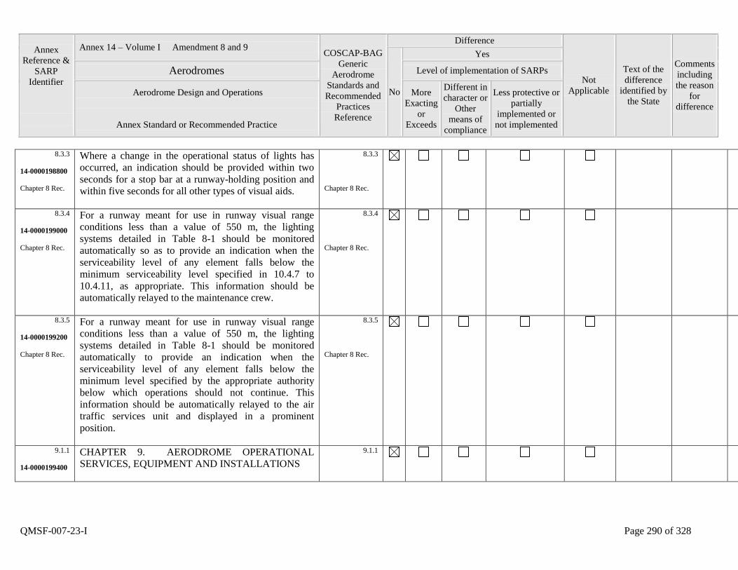
Annex
Reference &
SARP
Identifier
Annex 14 – Volume I Amendment 8 and 9 COSCAP-BAG
Generic
Aerodrome
Standards and
Recommended
Practices
Reference
Difference
Not
Applicable
Text of the
difference
identified by
the State
Comments
including
the reason
for
difference
No
Yes
Aerodromes Level of implementation of SARPs
Aerodrome Design and Operations
Annex Standard or Recommended Practice
More
Exacting
or
Exceeds
Different in
character or
Other
means of
compliance
Less protective or
partially
implemented or
not implemented
QMSF-007-23-I Page 290 of 328
8.3.3
14-0000198800
Chapter 8 Rec.
Where a change in the operational status of lights has
occurred, an indication should be provided within two
seconds for a stop bar at a runway-holding position and
within five seconds for all other types of visual aids.
8.3.3
Chapter 8 Rec.
8.3.4
14-0000199000
Chapter 8 Rec.
For a runway meant for use in runway visual range
conditions less than a value of 550 m, the lighting
systems detailed in Table 8-1 should be monitored
automatically so as to provide an indication when the
serviceability level of any element falls below the
minimum serviceability level specified in 10.4.7 to
10.4.11, as appropriate. This information should be
automatically relayed to the maintenance crew.
8.3.4
Chapter 8 Rec.
8.3.5
14-0000199200
Chapter 8 Rec.
For a runway meant for use in runway visual range
conditions less than a value of 550 m, the lighting
systems detailed in Table 8-1 should be monitored
automatically to provide an indication when the
serviceability level of any element falls below the
minimum level specified by the appropriate authority
below which operations should not continue. This
information should be automatically relayed to the air
traffic services unit and displayed in a prominent
position.
8.3.5
Chapter 8 Rec.
9.1.1
14-0000199400
CHAPTER 9. AERODROME OPERATIONAL
SERVICES, EQUIPMENT AND INSTALLATIONS
9.1.1
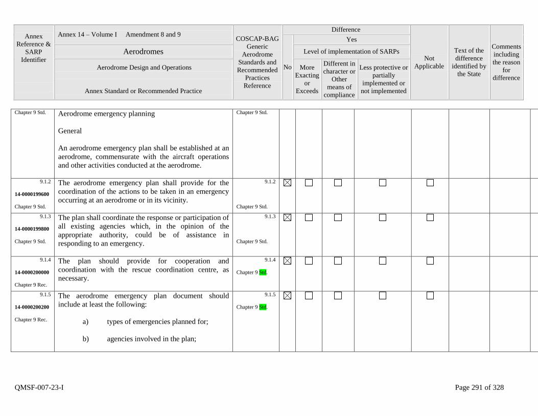
Annex
Reference &
SARP
Identifier
Annex 14 – Volume I Amendment 8 and 9 COSCAP-BAG
Generic
Aerodrome
Standards and
Recommended
Practices
Reference
Difference
Not
Applicable
Text of the
difference
identified by
the State
Comments
including
the reason
for
difference
No
Yes
Aerodromes Level of implementation of SARPs
Aerodrome Design and Operations
Annex Standard or Recommended Practice
More
Exacting
or
Exceeds
Different in
character or
Other
means of
compliance
Less protective or
partially
implemented or
not implemented
QMSF-007-23-I Page 291 of 328
Chapter 9 Std. Aerodrome emergency planning
General
An aerodrome emergency plan shall be established at an
aerodrome, commensurate with the aircraft operations
and other activities conducted at the aerodrome.
Chapter 9 Std.
9.1.2
14-0000199600
Chapter 9 Std.
The aerodrome emergency plan shall provide for the
coordination of the actions to be taken in an emergency
occurring at an aerodrome or in its vicinity.
9.1.2
Chapter 9 Std.
9.1.3
14-0000199800
Chapter 9 Std.
The plan shall coordinate the response or participation of
all existing agencies which, in the opinion of the
appropriate authority, could be of assistance in
responding to an emergency.
9.1.3
Chapter 9 Std.
9.1.4
14-0000200000
Chapter 9 Rec.
The plan should provide for cooperation and
coordination with the rescue coordination centre, as
necessary.
9.1.4
Chapter 9 Std.
9.1.5
14-0000200200
Chapter 9 Rec.
The aerodrome emergency plan document should
include at least the following:
a) types of emergencies planned for;
b) agencies involved in the plan;
9.1.5
Chapter 9 Std.
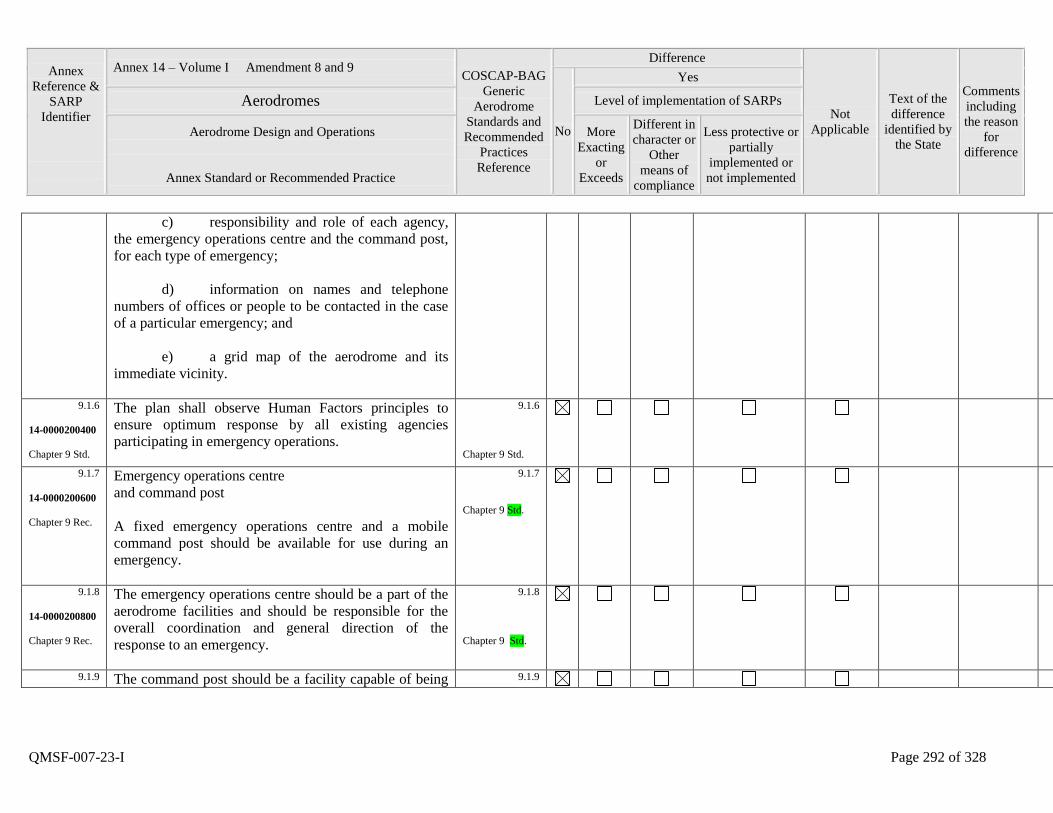
Annex
Reference &
SARP
Identifier
Annex 14 – Volume I Amendment 8 and 9 COSCAP-BAG
Generic
Aerodrome
Standards and
Recommended
Practices
Reference
Difference
Not
Applicable
Text of the
difference
identified by
the State
Comments
including
the reason
for
difference
No
Yes
Aerodromes Level of implementation of SARPs
Aerodrome Design and Operations
Annex Standard or Recommended Practice
More
Exacting
or
Exceeds
Different in
character or
Other
means of
compliance
Less protective or
partially
implemented or
not implemented
QMSF-007-23-I Page 292 of 328
c) responsibility and role of each agency,
the emergency operations centre and the command post,
for each type of emergency;
d) information on names and telephone
numbers of offices or people to be contacted in the case
of a particular emergency; and
e) a grid map of the aerodrome and its
immediate vicinity.
9.1.6
14-0000200400
Chapter 9 Std.
The plan shall observe Human Factors principles to
ensure optimum response by all existing agencies
participating in emergency operations.
9.1.6
Chapter 9 Std.
9.1.7
14-0000200600
Chapter 9 Rec.
Emergency operations centre
and command post
A fixed emergency operations centre and a mobile
command post should be available for use during an
emergency.
9.1.7
Chapter 9 Std.
9.1.8
14-0000200800
Chapter 9 Rec.
The emergency operations centre should be a part of the
aerodrome facilities and should be responsible for the
overall coordination and general direction of the
response to an emergency.
9.1.8
Chapter 9 Std.
9.1.9 The command post should be a facility capable of being 9.1.9
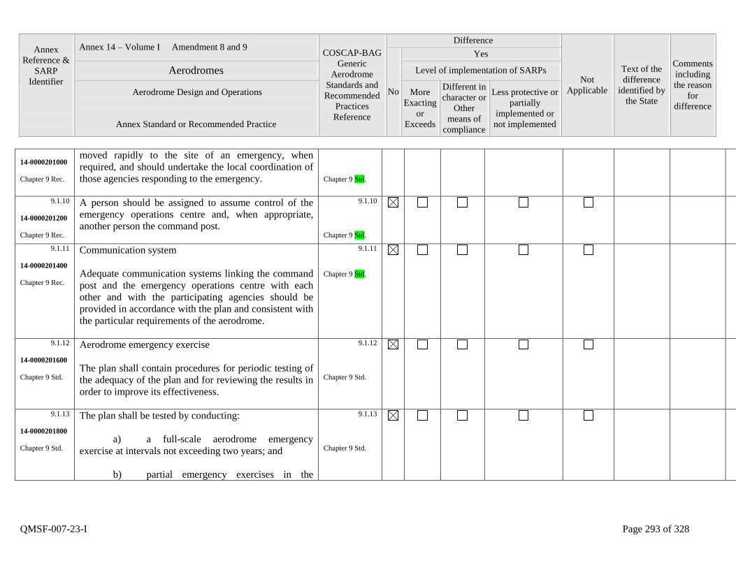
Annex
Reference &
SARP
Identifier
Annex 14 – Volume I Amendment 8 and 9 COSCAP-BAG
Generic
Aerodrome
Standards and
Recommended
Practices
Reference
Difference
Not
Applicable
Text of the
difference
identified by
the State
Comments
including
the reason
for
difference
No
Yes
Aerodromes Level of implementation of SARPs
Aerodrome Design and Operations
Annex Standard or Recommended Practice
More
Exacting
or
Exceeds
Different in
character or
Other
means of
compliance
Less protective or
partially
implemented or
not implemented
QMSF-007-23-I Page 293 of 328
14-0000201000
Chapter 9 Rec.
moved rapidly to the site of an emergency, when
required, and should undertake the local coordination of
those agencies responding to the emergency.
Chapter 9 Std.
9.1.10
14-0000201200
Chapter 9 Rec.
A person should be assigned to assume control of the
emergency operations centre and, when appropriate,
another person the command post.
9.1.10
Chapter 9 Std.
9.1.11
14-0000201400
Chapter 9 Rec.
Communication system
Adequate communication systems linking the command
post and the emergency operations centre with each
other and with the participating agencies should be
provided in accordance with the plan and consistent with
the particular requirements of the aerodrome.
9.1.11
Chapter 9 Std.
9.1.12
14-0000201600
Chapter 9 Std.
Aerodrome emergency exercise
The plan shall contain procedures for periodic testing of
the adequacy of the plan and for reviewing the results in
order to improve its effectiveness.
9.1.12
Chapter 9 Std.
9.1.13
14-0000201800
Chapter 9 Std.
The plan shall be tested by conducting:
a) a full-scale aerodrome emergency
exercise at intervals not exceeding two years; and
b) partial emergency exercises in the
9.1.13
Chapter 9 Std.
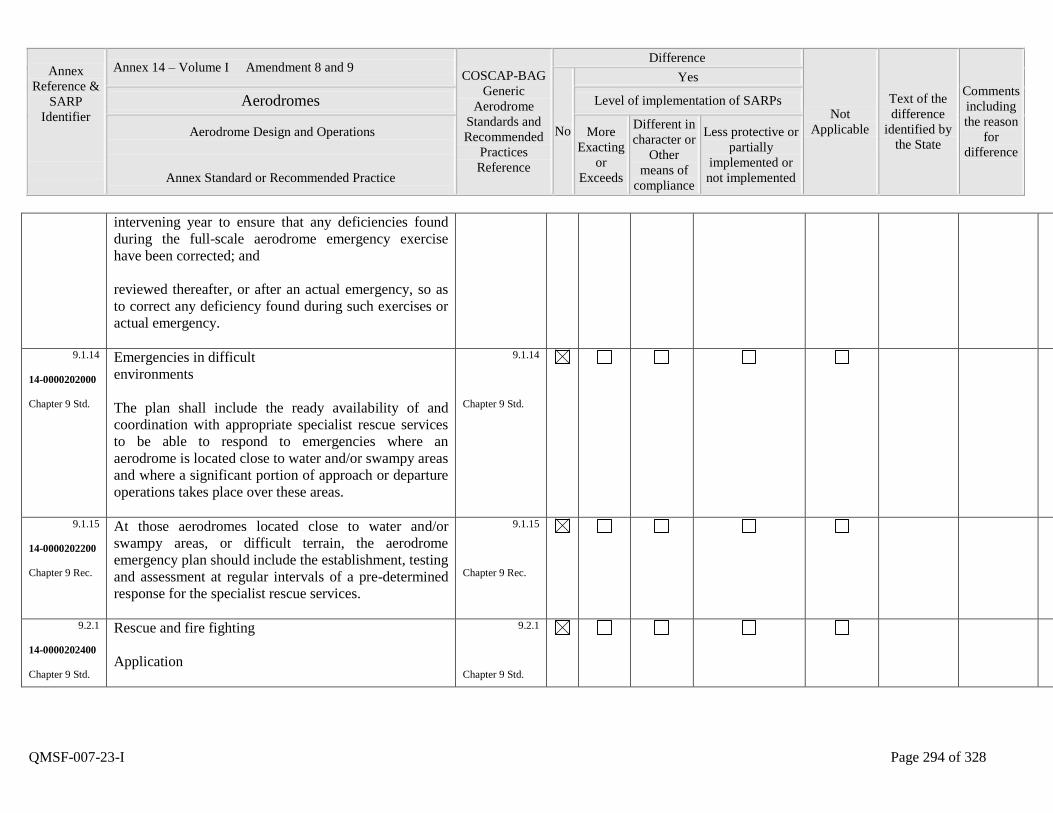
Annex
Reference &
SARP
Identifier
Annex 14 – Volume I Amendment 8 and 9 COSCAP-BAG
Generic
Aerodrome
Standards and
Recommended
Practices
Reference
Difference
Not
Applicable
Text of the
difference
identified by
the State
Comments
including
the reason
for
difference
No
Yes
Aerodromes Level of implementation of SARPs
Aerodrome Design and Operations
Annex Standard or Recommended Practice
More
Exacting
or
Exceeds
Different in
character or
Other
means of
compliance
Less protective or
partially
implemented or
not implemented
QMSF-007-23-I Page 294 of 328
intervening year to ensure that any deficiencies found
during the full-scale aerodrome emergency exercise
have been corrected; and
reviewed thereafter, or after an actual emergency, so as
to correct any deficiency found during such exercises or
actual emergency.
9.1.14
14-0000202000
Chapter 9 Std.
Emergencies in difficult
environments
The plan shall include the ready availability of and
coordination with appropriate specialist rescue services
to be able to respond to emergencies where an
aerodrome is located close to water and/or swampy areas
and where a significant portion of approach or departure
operations takes place over these areas.
9.1.14
Chapter 9 Std.
9.1.15
14-0000202200
Chapter 9 Rec.
At those aerodromes located close to water and/or
swampy areas, or difficult terrain, the aerodrome
emergency plan should include the establishment, testing
and assessment at regular intervals of a pre-determined
response for the specialist rescue services.
9.1.15
Chapter 9 Rec.
9.2.1
14-0000202400
Chapter 9 Std.
Rescue and fire fighting
Application
9.2.1
Chapter 9 Std.
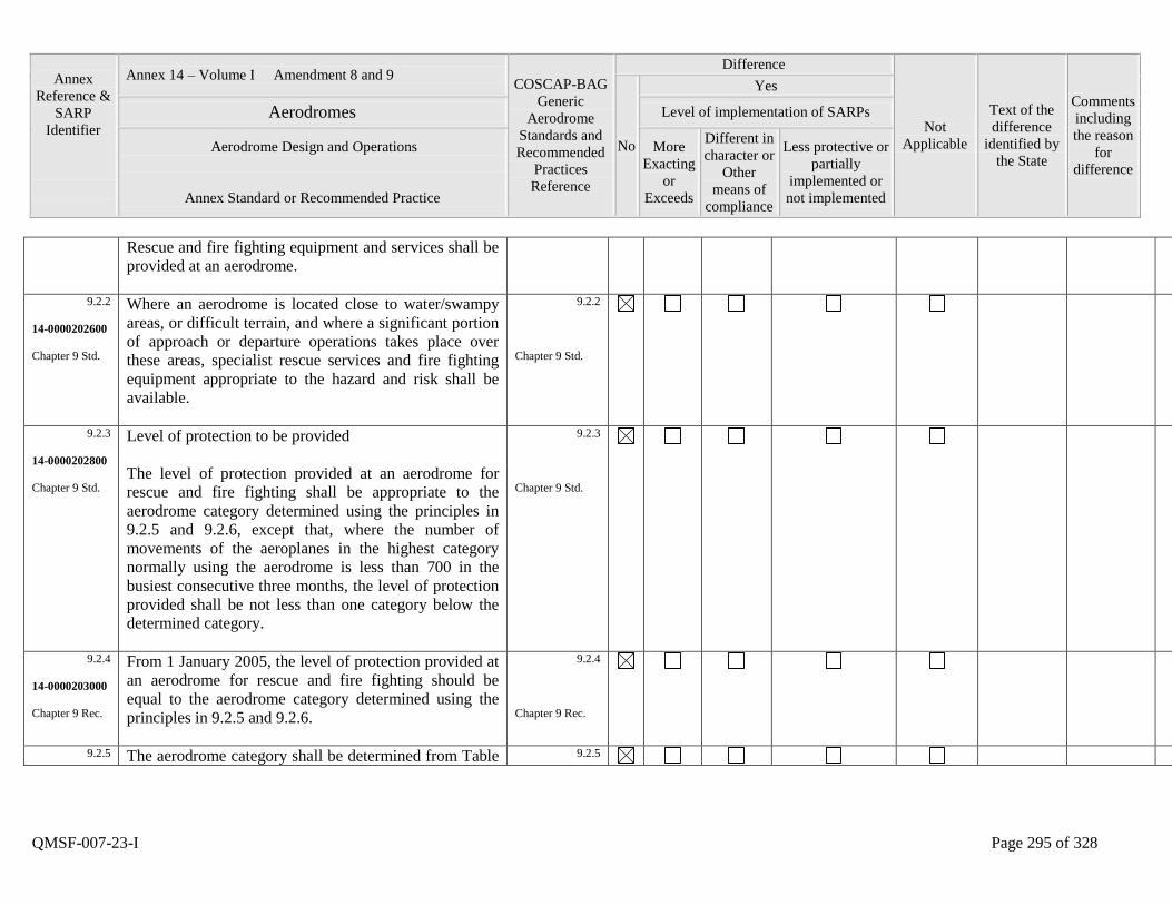
Annex
Reference &
SARP
Identifier
Annex 14 – Volume I Amendment 8 and 9 COSCAP-BAG
Generic
Aerodrome
Standards and
Recommended
Practices
Reference
Difference
Not
Applicable
Text of the
difference
identified by
the State
Comments
including
the reason
for
difference
No
Yes
Aerodromes Level of implementation of SARPs
Aerodrome Design and Operations
Annex Standard or Recommended Practice
More
Exacting
or
Exceeds
Different in
character or
Other
means of
compliance
Less protective or
partially
implemented or
not implemented
QMSF-007-23-I Page 295 of 328
Rescue and fire fighting equipment and services shall be
provided at an aerodrome.
9.2.2
14-0000202600
Chapter 9 Std.
Where an aerodrome is located close to water/swampy
areas, or difficult terrain, and where a significant portion
of approach or departure operations takes place over
these areas, specialist rescue services and fire fighting
equipment appropriate to the hazard and risk shall be
available.
9.2.2
Chapter 9 Std.
9.2.3
14-0000202800
Chapter 9 Std.
Level of protection to be provided
The level of protection provided at an aerodrome for
rescue and fire fighting shall be appropriate to the
aerodrome category determined using the principles in
9.2.5 and 9.2.6, except that, where the number of
movements of the aeroplanes in the highest category
normally using the aerodrome is less than 700 in the
busiest consecutive three months, the level of protection
provided shall be not less than one category below the
determined category.
9.2.3
Chapter 9 Std.
9.2.4
14-0000203000
Chapter 9 Rec.
From 1 January 2005, the level of protection provided at
an aerodrome for rescue and fire fighting should be
equal to the aerodrome category determined using the
principles in 9.2.5 and 9.2.6.
9.2.4
Chapter 9 Rec.
9.2.5 The aerodrome category shall be determined from Table 9.2.5
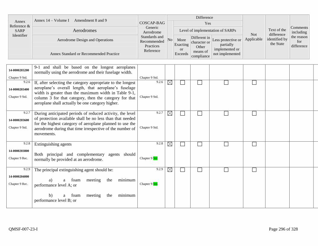
Annex
Reference &
SARP
Identifier
Annex 14 – Volume I Amendment 8 and 9 COSCAP-BAG
Generic
Aerodrome
Standards and
Recommended
Practices
Reference
Difference
Not
Applicable
Text of the
difference
identified by
the State
Comments
including
the reason
for
difference
No
Yes
Aerodromes Level of implementation of SARPs
Aerodrome Design and Operations
Annex Standard or Recommended Practice
More
Exacting
or
Exceeds
Different in
character or
Other
means of
compliance
Less protective or
partially
implemented or
not implemented
QMSF-007-23-I Page 296 of 328
14-0000203200
Chapter 9 Std.
9-1 and shall be based on the longest aeroplanes
normally using the aerodrome and their fuselage width.
Chapter 9 Std.
9.2.6
14-0000203400
Chapter 9 Std.
If, after selecting the category appropriate to the longest
aeroplane‟s overall length, that aeroplane‟s fuselage
width is greater than the maximum width in Table 9-1,
column 3 for that category, then the category for that
aeroplane shall actually be one category higher.
9.2.6
Chapter 9 Std.
9.2.7
14-0000203600
Chapter 9 Std.
During anticipated periods of reduced activity, the level
of protection available shall be no less than that needed
for the highest category of aeroplane planned to use the
aerodrome during that time irrespective of the number of
movements.
9.2.7
Chapter 9 Std.
9.2.8
14-0000203800
Chapter 9 Rec.
Extinguishing agents
Both principal and complementary agents should
normally be provided at an aerodrome.
9.2.8
Chapter 9 Std.
9.2.9
14-0000204000
Chapter 9 Rec.
The principal extinguishing agent should be:
a) a foam meeting the minimum
performance level A; or
b) a foam meeting the minimum
performance level B; or
9.2.9
Chapter 9 Std.
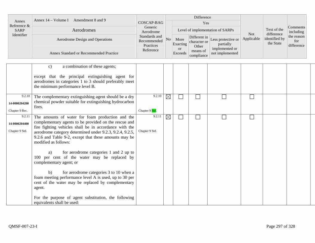
Annex
Reference &
SARP
Identifier
Annex 14 – Volume I Amendment 8 and 9 COSCAP-BAG
Generic
Aerodrome
Standards and
Recommended
Practices
Reference
Difference
Not
Applicable
Text of the
difference
identified by
the State
Comments
including
the reason
for
difference
No
Yes
Aerodromes Level of implementation of SARPs
Aerodrome Design and Operations
Annex Standard or Recommended Practice
More
Exacting
or
Exceeds
Different in
character or
Other
means of
compliance
Less protective or
partially
implemented or
not implemented
QMSF-007-23-I Page 297 of 328
c) a combination of these agents;
except that the principal extinguishing agent for
aerodromes in categories 1 to 3 should preferably meet
the minimum performance level B.
9.2.10
14-0000204200
Chapter 9 Rec.
The complementary extinguishing agent should be a dry
chemical powder suitable for extinguishing hydrocarbon
fires.
9.2.10
Chapter 9 Std.
9.2.11
14-0000204400
Chapter 9 Std.
The amounts of water for foam production and the
complementary agents to be provided on the rescue and
fire fighting vehicles shall be in accordance with the
aerodrome category determined under 9.2.3, 9.2.4, 9.2.5,
9.2.6 and Table 9-2, except that these amounts may be
modified as follows:
a) for aerodrome categories 1 and 2 up to
100 per cent of the water may be replaced by
complementary agent; or
b) for aerodrome categories 3 to 10 when a
foam meeting performance level A is used, up to 30 per
cent of the water may be replaced by complementary
agent.
For the purpose of agent substitution, the following
equivalents shall be used:
9.2.11
Chapter 9 Std.
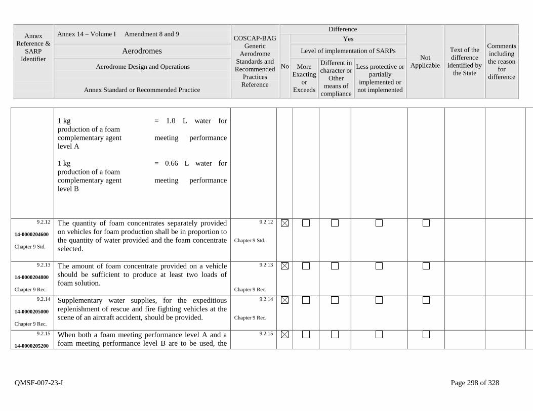
Annex
Reference &
SARP
Identifier
Annex 14 – Volume I Amendment 8 and 9 COSCAP-BAG
Generic
Aerodrome
Standards and
Recommended
Practices
Reference
Difference
Not
Applicable
Text of the
difference
identified by
the State
Comments
including
the reason
for
difference
No
Yes
Aerodromes Level of implementation of SARPs
Aerodrome Design and Operations
Annex Standard or Recommended Practice
More
Exacting
or
Exceeds
Different in
character or
Other
means of
compliance
Less protective or
partially
implemented or
not implemented
QMSF-007-23-I Page 298 of 328
1 kg = 1.0 L water for
production of a foam
complementary agent meeting performance
level A
1 kg = 0.66 L water for
production of a foam
complementary agent meeting performance
level B
9.2.12
14-0000204600
Chapter 9 Std.
The quantity of foam concentrates separately provided
on vehicles for foam production shall be in proportion to
the quantity of water provided and the foam concentrate
selected.
9.2.12
Chapter 9 Std.
9.2.13
14-0000204800
Chapter 9 Rec.
The amount of foam concentrate provided on a vehicle
should be sufficient to produce at least two loads of
foam solution.
9.2.13
Chapter 9 Rec.
9.2.14
14-0000205000
Chapter 9 Rec.
Supplementary water supplies, for the expeditious
replenishment of rescue and fire fighting vehicles at the
scene of an aircraft accident, should be provided.
9.2.14
Chapter 9 Rec.
9.2.15
14-0000205200
When both a foam meeting performance level A and a
foam meeting performance level B are to be used, the
9.2.15
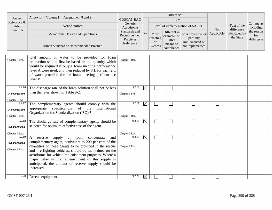
Annex
Reference &
SARP
Identifier
Annex 14 – Volume I Amendment 8 and 9 COSCAP-BAG
Generic
Aerodrome
Standards and
Recommended
Practices
Reference
Difference
Not
Applicable
Text of the
difference
identified by
the State
Comments
including
the reason
for
difference
No
Yes
Aerodromes Level of implementation of SARPs
Aerodrome Design and Operations
Annex Standard or Recommended Practice
More
Exacting
or
Exceeds
Different in
character or
Other
means of
compliance
Less protective or
partially
implemented or
not implemented
QMSF-007-23-I Page 299 of 328
Chapter 9 Rec. total amount of water to be provided for foam
production should first be based on the quantity which
would be required if only a foam meeting performance
level A were used, and then reduced by 3 L for each 2 L
of water provided for the foam meeting performance
level B.
Chapter 9 Rec.
9.2.16
14-0000205400
Chapter 9 Std.
The discharge rate of the foam solution shall not be less
than the rates shown in Table 9-2.
9.2.16
Chapter 9 Std.
9.2.17
14-0000205600
Chapter 9 Rec.
The complementary agents should comply with the
appropriate specifications of the International
Organization for Standardization (ISO).*
9.2.17
Chapter 9 Rec.
9.2.18
14-0000205800
Chapter 9 Rec.
The discharge rate of complementary agents should be
selected for optimum effectiveness of the agent.
9.2.18
Chapter 9 Rec.
9.2.19
14-0000206000
Chapter 9 Rec.
A reserve supply of foam concentrate and
complementary agent, equivalent to 200 per cent of the
quantities of these agents to be provided in the rescue
and fire fighting vehicles, should be maintained on the
aerodrome for vehicle replenishment purposes. Where a
major delay in the replenishment of this supply is
anticipated, the amount of reserve supply should be
increased.
9.2.19
Chapter 9 Rec.
9.2.20 Rescue equipment 9.2.20
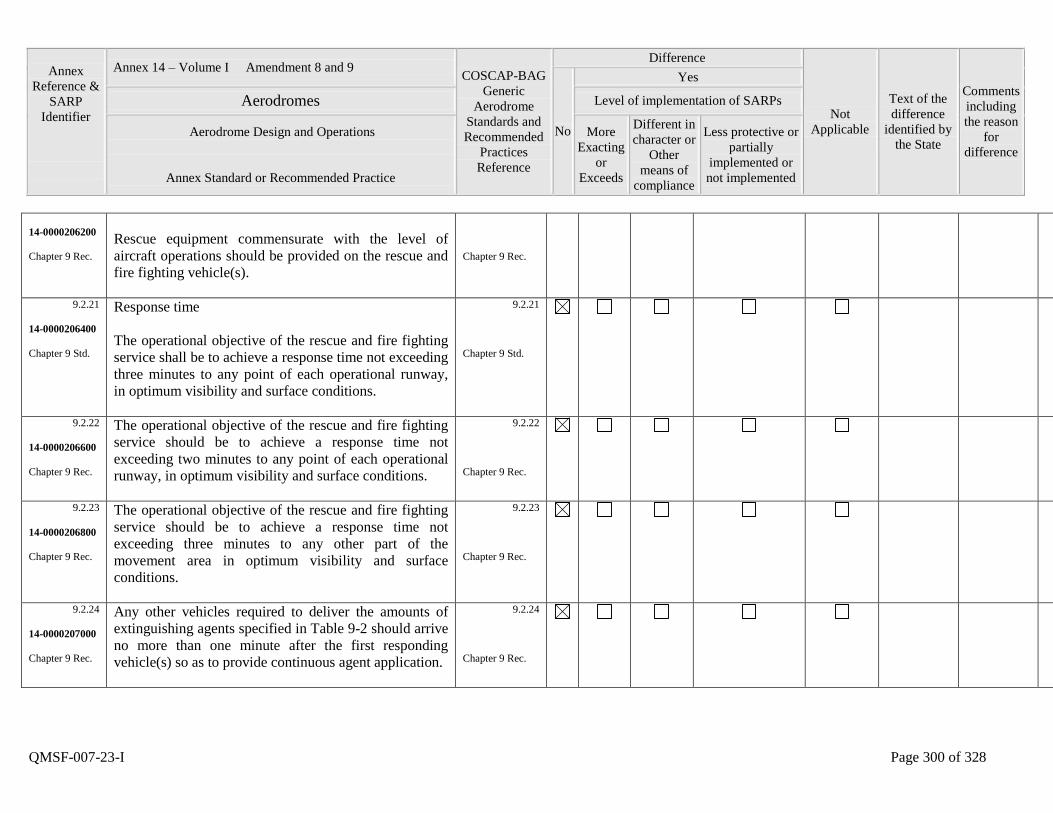
Annex
Reference &
SARP
Identifier
Annex 14 – Volume I Amendment 8 and 9 COSCAP-BAG
Generic
Aerodrome
Standards and
Recommended
Practices
Reference
Difference
Not
Applicable
Text of the
difference
identified by
the State
Comments
including
the reason
for
difference
No
Yes
Aerodromes Level of implementation of SARPs
Aerodrome Design and Operations
Annex Standard or Recommended Practice
More
Exacting
or
Exceeds
Different in
character or
Other
means of
compliance
Less protective or
partially
implemented or
not implemented
QMSF-007-23-I Page 300 of 328
14-0000206200
Chapter 9 Rec.
Rescue equipment commensurate with the level of
aircraft operations should be provided on the rescue and
fire fighting vehicle(s).
Chapter 9 Rec.
9.2.21
14-0000206400
Chapter 9 Std.
Response time
The operational objective of the rescue and fire fighting
service shall be to achieve a response time not exceeding
three minutes to any point of each operational runway,
in optimum visibility and surface conditions.
9.2.21
Chapter 9 Std.
9.2.22
14-0000206600
Chapter 9 Rec.
The operational objective of the rescue and fire fighting
service should be to achieve a response time not
exceeding two minutes to any point of each operational
runway, in optimum visibility and surface conditions.
9.2.22
Chapter 9 Rec.
9.2.23
14-0000206800
Chapter 9 Rec.
The operational objective of the rescue and fire fighting
service should be to achieve a response time not
exceeding three minutes to any other part of the
movement area in optimum visibility and surface
conditions.
9.2.23
Chapter 9 Rec.
9.2.24
14-0000207000
Chapter 9 Rec.
Any other vehicles required to deliver the amounts of
extinguishing agents specified in Table 9-2 should arrive
no more than one minute after the first responding
vehicle(s) so as to provide continuous agent application.
9.2.24
Chapter 9 Rec.
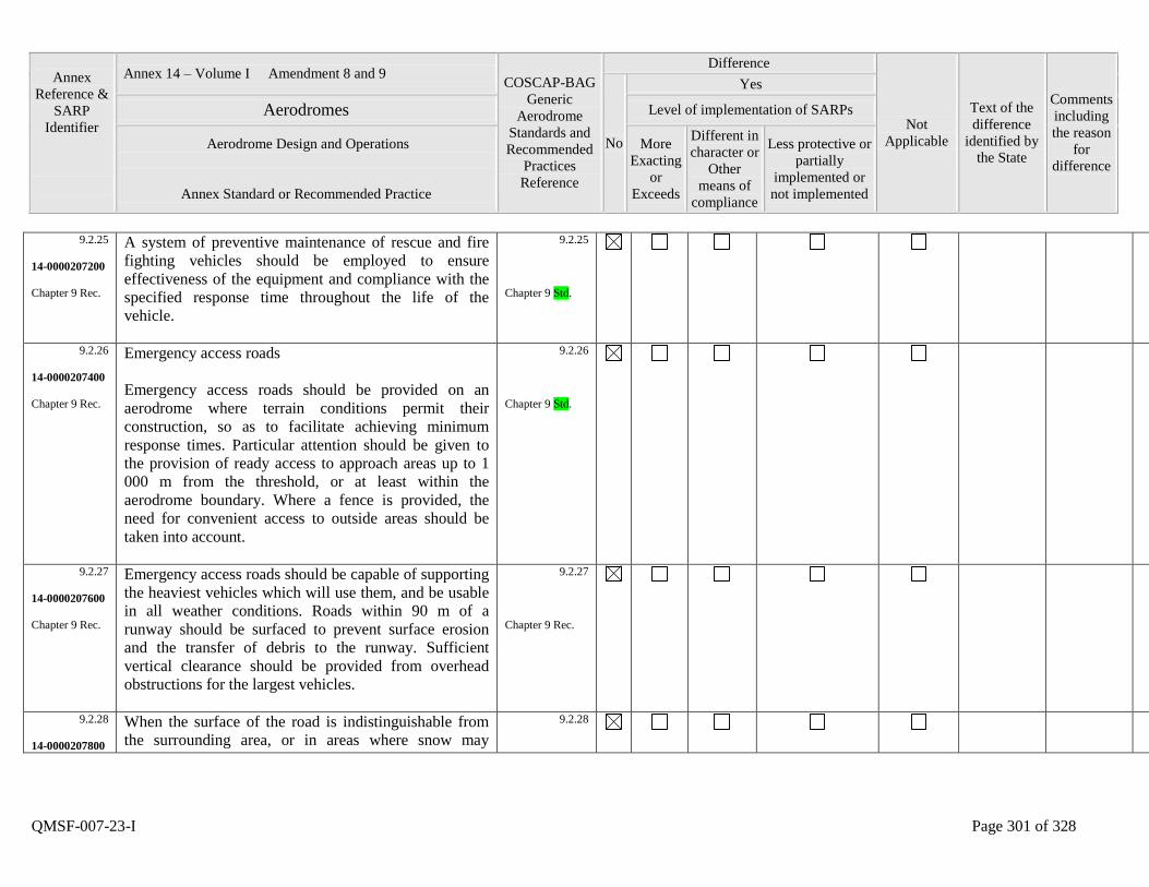
Annex
Reference &
SARP
Identifier
Annex 14 – Volume I Amendment 8 and 9 COSCAP-BAG
Generic
Aerodrome
Standards and
Recommended
Practices
Reference
Difference
Not
Applicable
Text of the
difference
identified by
the State
Comments
including
the reason
for
difference
No
Yes
Aerodromes Level of implementation of SARPs
Aerodrome Design and Operations
Annex Standard or Recommended Practice
More
Exacting
or
Exceeds
Different in
character or
Other
means of
compliance
Less protective or
partially
implemented or
not implemented
QMSF-007-23-I Page 301 of 328
9.2.25
14-0000207200
Chapter 9 Rec.
A system of preventive maintenance of rescue and fire
fighting vehicles should be employed to ensure
effectiveness of the equipment and compliance with the
specified response time throughout the life of the
vehicle.
9.2.25
Chapter 9 Std.
9.2.26
14-0000207400
Chapter 9 Rec.
Emergency access roads
Emergency access roads should be provided on an
aerodrome where terrain conditions permit their
construction, so as to facilitate achieving minimum
response times. Particular attention should be given to
the provision of ready access to approach areas up to 1
000 m from the threshold, or at least within the
aerodrome boundary. Where a fence is provided, the
need for convenient access to outside areas should be
taken into account.
9.2.26
Chapter 9 Std.
9.2.27
14-0000207600
Chapter 9 Rec.
Emergency access roads should be capable of supporting
the heaviest vehicles which will use them, and be usable
in all weather conditions. Roads within 90 m of a
runway should be surfaced to prevent surface erosion
and the transfer of debris to the runway. Sufficient
vertical clearance should be provided from overhead
obstructions for the largest vehicles.
9.2.27
Chapter 9 Rec.
9.2.28
14-0000207800
When the surface of the road is indistinguishable from
the surrounding area, or in areas where snow may
9.2.28
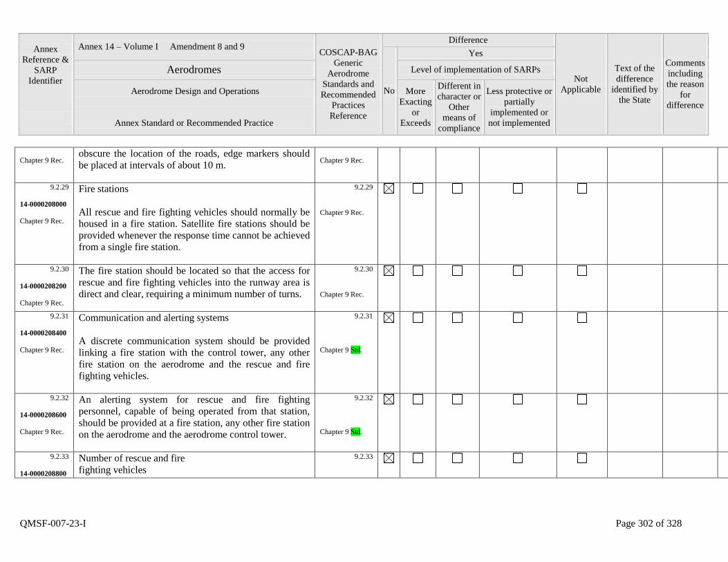
Annex
Reference &
SARP
Identifier
Annex 14 – Volume I Amendment 8 and 9 COSCAP-BAG
Generic
Aerodrome
Standards and
Recommended
Practices
Reference
Difference
Not
Applicable
Text of the
difference
identified by
the State
Comments
including
the reason
for
difference
No
Yes
Aerodromes Level of implementation of SARPs
Aerodrome Design and Operations
Annex Standard or Recommended Practice
More
Exacting
or
Exceeds
Different in
character or
Other
means of
compliance
Less protective or
partially
implemented or
not implemented
QMSF-007-23-I Page 302 of 328
Chapter 9 Rec. obscure the location of the roads, edge markers should
be placed at intervals of about 10 m.
Chapter 9 Rec.
9.2.29
14-0000208000
Chapter 9 Rec.
Fire stations
All rescue and fire fighting vehicles should normally be
housed in a fire station. Satellite fire stations should be
provided whenever the response time cannot be achieved
from a single fire station.
9.2.29
Chapter 9 Rec.
9.2.30
14-0000208200
Chapter 9 Rec.
The fire station should be located so that the access for
rescue and fire fighting vehicles into the runway area is
direct and clear, requiring a minimum number of turns.
9.2.30
Chapter 9 Rec.
9.2.31
14-0000208400
Chapter 9 Rec.
Communication and alerting systems
A discrete communication system should be provided
linking a fire station with the control tower, any other
fire station on the aerodrome and the rescue and fire
fighting vehicles.
9.2.31
Chapter 9 Std.
9.2.32
14-0000208600
Chapter 9 Rec.
An alerting system for rescue and fire fighting
personnel, capable of being operated from that station,
should be provided at a fire station, any other fire station
on the aerodrome and the aerodrome control tower.
9.2.32
Chapter 9 Std.
9.2.33
14-0000208800
Number of rescue and fire
fighting vehicles
9.2.33
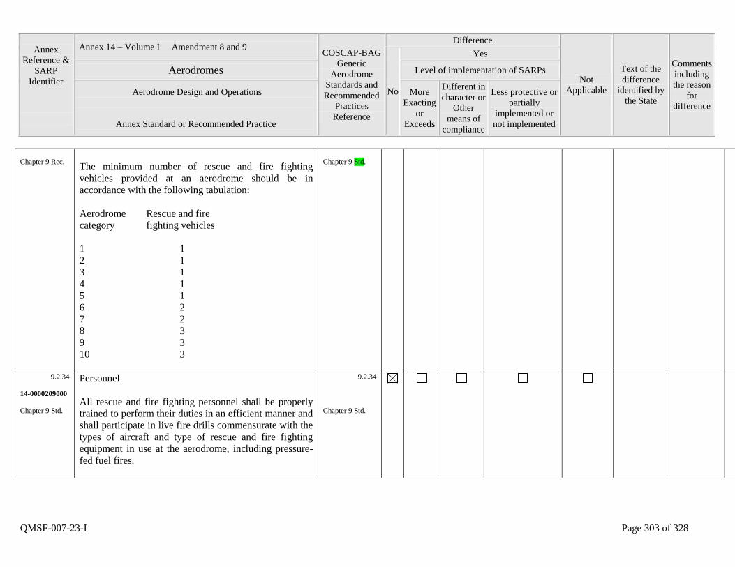
Annex
Reference &
SARP
Identifier
Annex 14 – Volume I Amendment 8 and 9 COSCAP-BAG
Generic
Aerodrome
Standards and
Recommended
Practices
Reference
Difference
Not
Applicable
Text of the
difference
identified by
the State
Comments
including
the reason
for
difference
No
Yes
Aerodromes Level of implementation of SARPs
Aerodrome Design and Operations
Annex Standard or Recommended Practice
More
Exacting
or
Exceeds
Different in
character or
Other
means of
compliance
Less protective or
partially
implemented or
not implemented
QMSF-007-23-I Page 303 of 328
Chapter 9 Rec.
The minimum number of rescue and fire fighting
vehicles provided at an aerodrome should be in
accordance with the following tabulation:
Aerodrome Rescue and fire
category fighting vehicles
1 1
2 1
3 1
4 1
5 1
6 2
7 2
8 3
9 3
10 3
Chapter 9 Std.
9.2.34
14-0000209000
Chapter 9 Std.
Personnel
All rescue and fire fighting personnel shall be properly
trained to perform their duties in an efficient manner and
shall participate in live fire drills commensurate with the
types of aircraft and type of rescue and fire fighting
equipment in use at the aerodrome, including pressure-
fed fuel fires.
9.2.34
Chapter 9 Std.
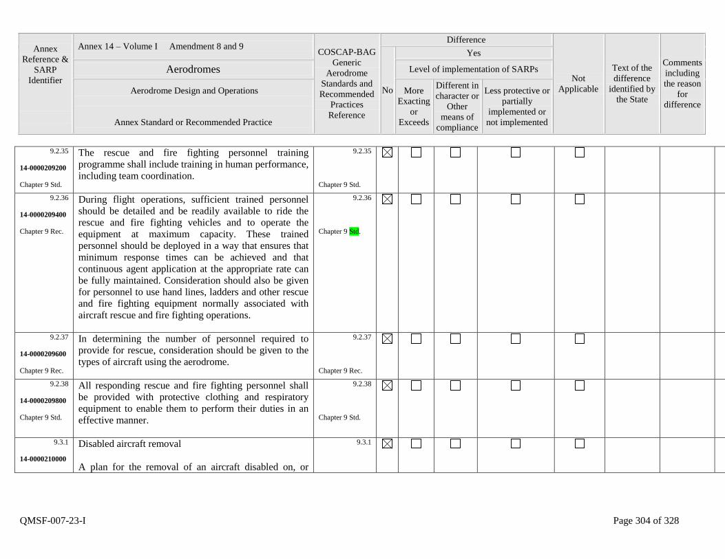
Annex
Reference &
SARP
Identifier
Annex 14 – Volume I Amendment 8 and 9 COSCAP-BAG
Generic
Aerodrome
Standards and
Recommended
Practices
Reference
Difference
Not
Applicable
Text of the
difference
identified by
the State
Comments
including
the reason
for
difference
No
Yes
Aerodromes Level of implementation of SARPs
Aerodrome Design and Operations
Annex Standard or Recommended Practice
More
Exacting
or
Exceeds
Different in
character or
Other
means of
compliance
Less protective or
partially
implemented or
not implemented
QMSF-007-23-I Page 304 of 328
9.2.35
14-0000209200
Chapter 9 Std.
The rescue and fire fighting personnel training
programme shall include training in human performance,
including team coordination.
9.2.35
Chapter 9 Std.
9.2.36
14-0000209400
Chapter 9 Rec.
During flight operations, sufficient trained personnel
should be detailed and be readily available to ride the
rescue and fire fighting vehicles and to operate the
equipment at maximum capacity. These trained
personnel should be deployed in a way that ensures that
minimum response times can be achieved and that
continuous agent application at the appropriate rate can
be fully maintained. Consideration should also be given
for personnel to use hand lines, ladders and other rescue
and fire fighting equipment normally associated with
aircraft rescue and fire fighting operations.
9.2.36
Chapter 9 Std.
9.2.37
14-0000209600
Chapter 9 Rec.
In determining the number of personnel required to
provide for rescue, consideration should be given to the
types of aircraft using the aerodrome.
9.2.37
Chapter 9 Rec.
9.2.38
14-0000209800
Chapter 9 Std.
All responding rescue and fire fighting personnel shall
be provided with protective clothing and respiratory
equipment to enable them to perform their duties in an
effective manner.
9.2.38
Chapter 9 Std.
9.3.1
14-0000210000
Disabled aircraft removal
A plan for the removal of an aircraft disabled on, or
9.3.1
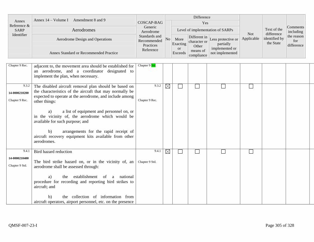
Annex
Reference &
SARP
Identifier
Annex 14 – Volume I Amendment 8 and 9 COSCAP-BAG
Generic
Aerodrome
Standards and
Recommended
Practices
Reference
Difference
Not
Applicable
Text of the
difference
identified by
the State
Comments
including
the reason
for
difference
No
Yes
Aerodromes Level of implementation of SARPs
Aerodrome Design and Operations
Annex Standard or Recommended Practice
More
Exacting
or
Exceeds
Different in
character or
Other
means of
compliance
Less protective or
partially
implemented or
not implemented
QMSF-007-23-I Page 305 of 328
Chapter 9 Rec. adjacent to, the movement area should be established for
an aerodrome, and a coordinator designated to
implement the plan, when necessary.
Chapter 9 Std.
9.3.2
14-0000210200
Chapter 9 Rec.
The disabled aircraft removal plan should be based on
the characteristics of the aircraft that may normally be
expected to operate at the aerodrome, and include among
other things:
a) a list of equipment and personnel on, or
in the vicinity of, the aerodrome which would be
available for such purpose; and
b) arrangements for the rapid receipt of
aircraft recovery equipment kits available from other
aerodromes.
9.3.2
Chapter 9 Rec.
9.4.1
14-0000210400
Chapter 9 Std.
Bird hazard reduction
The bird strike hazard on, or in the vicinity of, an
aerodrome shall be assessed through:
a) the establishment of a national
procedure for recording and reporting bird strikes to
aircraft; and
b) the collection of information from
aircraft operators, airport personnel, etc. on the presence
9.4.1
Chapter 9 Std.
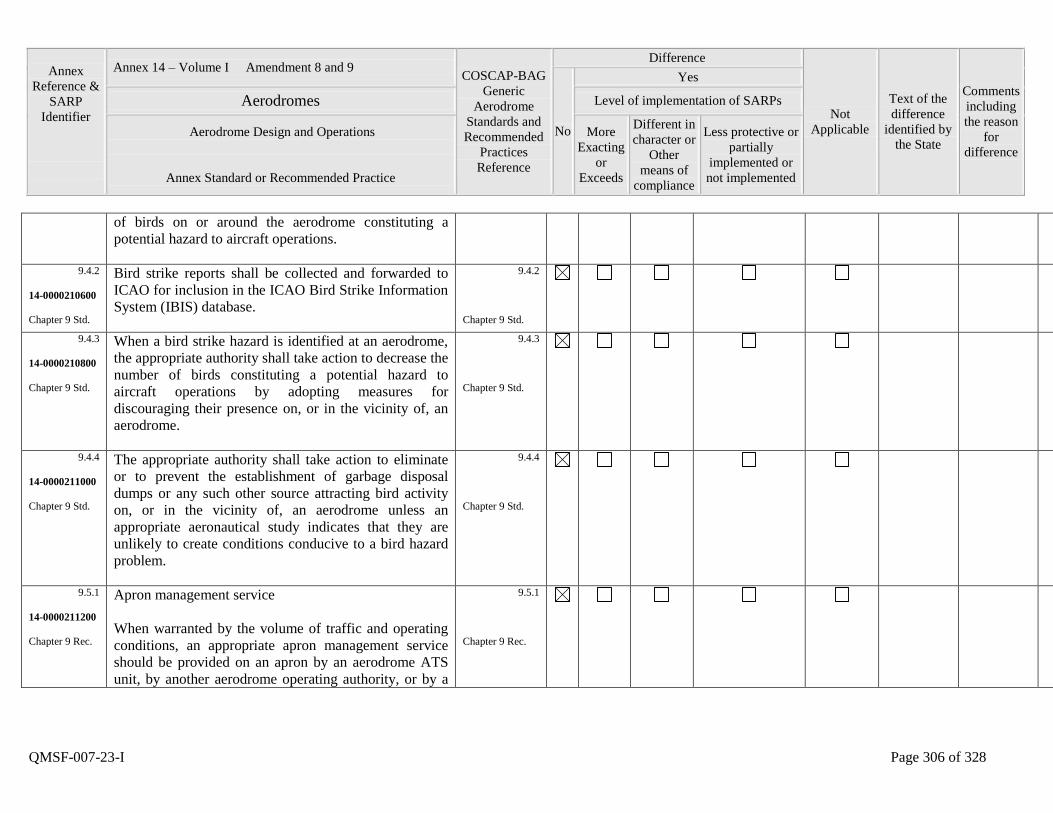
Annex
Reference &
SARP
Identifier
Annex 14 – Volume I Amendment 8 and 9 COSCAP-BAG
Generic
Aerodrome
Standards and
Recommended
Practices
Reference
Difference
Not
Applicable
Text of the
difference
identified by
the State
Comments
including
the reason
for
difference
No
Yes
Aerodromes Level of implementation of SARPs
Aerodrome Design and Operations
Annex Standard or Recommended Practice
More
Exacting
or
Exceeds
Different in
character or
Other
means of
compliance
Less protective or
partially
implemented or
not implemented
QMSF-007-23-I Page 306 of 328
of birds on or around the aerodrome constituting a
potential hazard to aircraft operations.
9.4.2
14-0000210600
Chapter 9 Std.
Bird strike reports shall be collected and forwarded to
ICAO for inclusion in the ICAO Bird Strike Information
System (IBIS) database.
9.4.2
Chapter 9 Std.
9.4.3
14-0000210800
Chapter 9 Std.
When a bird strike hazard is identified at an aerodrome,
the appropriate authority shall take action to decrease the
number of birds constituting a potential hazard to
aircraft operations by adopting measures for
discouraging their presence on, or in the vicinity of, an
aerodrome.
9.4.3
Chapter 9 Std.
9.4.4
14-0000211000
Chapter 9 Std.
The appropriate authority shall take action to eliminate
or to prevent the establishment of garbage disposal
dumps or any such other source attracting bird activity
on, or in the vicinity of, an aerodrome unless an
appropriate aeronautical study indicates that they are
unlikely to create conditions conducive to a bird hazard
problem.
9.4.4
Chapter 9 Std.
9.5.1
14-0000211200
Chapter 9 Rec.
Apron management service
When warranted by the volume of traffic and operating
conditions, an appropriate apron management service
should be provided on an apron by an aerodrome ATS
unit, by another aerodrome operating authority, or by a
9.5.1
Chapter 9 Rec.
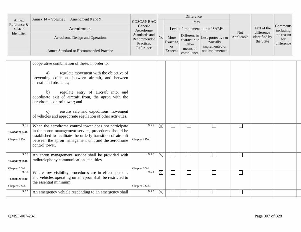
Annex
Reference &
SARP
Identifier
Annex 14 – Volume I Amendment 8 and 9 COSCAP-BAG
Generic
Aerodrome
Standards and
Recommended
Practices
Reference
Difference
Not
Applicable
Text of the
difference
identified by
the State
Comments
including
the reason
for
difference
No
Yes
Aerodromes Level of implementation of SARPs
Aerodrome Design and Operations
Annex Standard or Recommended Practice
More
Exacting
or
Exceeds
Different in
character or
Other
means of
compliance
Less protective or
partially
implemented or
not implemented
QMSF-007-23-I Page 307 of 328
cooperative combination of these, in order to:
a) regulate movement with the objective of
preventing collisions between aircraft, and between
aircraft and obstacles;
b) regulate entry of aircraft into, and
coordinate exit of aircraft from, the apron with the
aerodrome control tower; and
c) ensure safe and expeditious movement
of vehicles and appropriate regulation of other activities.
9.5.2
14-0000211400
Chapter 9 Rec.
When the aerodrome control tower does not participate
in the apron management service, procedures should be
established to facilitate the orderly transition of aircraft
between the apron management unit and the aerodrome
control tower.
9.5.2
Chapter 9 Rec.
9.5.3
14-0000211600
Chapter 9 Std.
An apron management service shall be provided with
radiotelephony communications facilities.
9.5.3
Chapter 9 Std.
9.5.4
14-0000211800
Chapter 9 Std.
Where low visibility procedures are in effect, persons
and vehicles operating on an apron shall be restricted to
the essential minimum.
9.5.4
Chapter 9 Std.
9.5.5
An emergency vehicle responding to an emergency shall 9.5.5
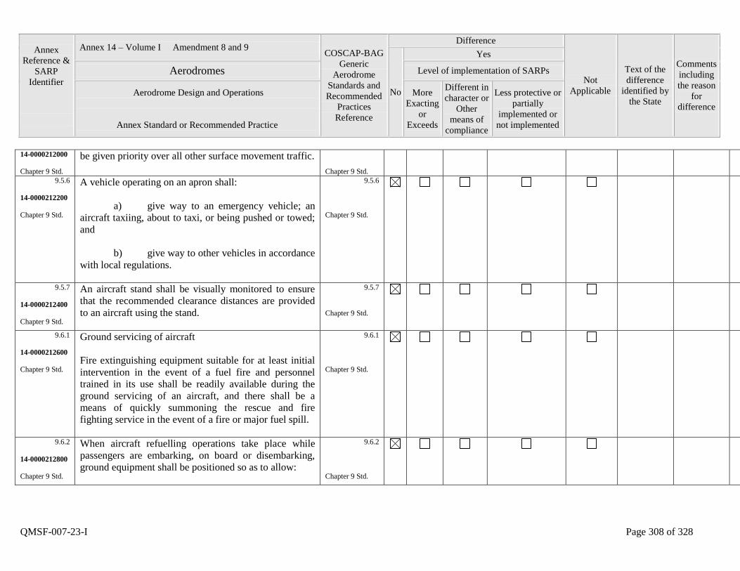
Annex
Reference &
SARP
Identifier
Annex 14 – Volume I Amendment 8 and 9 COSCAP-BAG
Generic
Aerodrome
Standards and
Recommended
Practices
Reference
Difference
Not
Applicable
Text of the
difference
identified by
the State
Comments
including
the reason
for
difference
No
Yes
Aerodromes Level of implementation of SARPs
Aerodrome Design and Operations
Annex Standard or Recommended Practice
More
Exacting
or
Exceeds
Different in
character or
Other
means of
compliance
Less protective or
partially
implemented or
not implemented
QMSF-007-23-I Page 308 of 328
14-0000212000
Chapter 9 Std.
be given priority over all other surface movement traffic.
Chapter 9 Std.
9.5.6
14-0000212200
Chapter 9 Std.
A vehicle operating on an apron shall:
a) give way to an emergency vehicle; an
aircraft taxiing, about to taxi, or being pushed or towed;
and
b) give way to other vehicles in accordance
with local regulations.
9.5.6
Chapter 9 Std.
9.5.7
14-0000212400
Chapter 9 Std.
An aircraft stand shall be visually monitored to ensure
that the recommended clearance distances are provided
to an aircraft using the stand.
9.5.7
Chapter 9 Std.
9.6.1
14-0000212600
Chapter 9 Std.
Ground servicing of aircraft
Fire extinguishing equipment suitable for at least initial
intervention in the event of a fuel fire and personnel
trained in its use shall be readily available during the
ground servicing of an aircraft, and there shall be a
means of quickly summoning the rescue and fire
fighting service in the event of a fire or major fuel spill.
9.6.1
Chapter 9 Std.
9.6.2
14-0000212800
Chapter 9 Std.
When aircraft refuelling operations take place while
passengers are embarking, on board or disembarking,
ground equipment shall be positioned so as to allow:
9.6.2
Chapter 9 Std.

Annex
Reference &
SARP
Identifier
Annex 14 – Volume I Amendment 8 and 9 COSCAP-BAG
Generic
Aerodrome
Standards and
Recommended
Practices
Reference
Difference
Not
Applicable
Text of the
difference
identified by
the State
Comments
including
the reason
for
difference
No
Yes
Aerodromes Level of implementation of SARPs
Aerodrome Design and Operations
Annex Standard or Recommended Practice
More
Exacting
or
Exceeds
Different in
character or
Other
means of
compliance
Less protective or
partially
implemented or
not implemented
QMSF-007-23-I Page 309 of 328
a) the use of a sufficient number of exits
for expeditious evacuation; and
b) a ready escape route from each of the
exits to be used in an emergency.
9.7.1
14-0000213000
Chapter 9 Std.
Aerodrome vehicle operations
A vehicle shall be operated:
a) on a manoeuvring area only as
authorized by the aerodrome control tower; and
b) on an apron only as authorized by the
appropriate designated authority.
9.7.1
Chapter 9 Std.
9.7.2
14-0000213200
Chapter 9 Std.
The driver of a vehicle on the movement area shall
comply with all mandatory instructions conveyed by
markings and signs unless otherwise authorized by:
a) the aerodrome control tower when on
the manoeuvring area; or
b) the appropriate designated authority
when on the apron.
9.7.2
Chapter 9 Std.
9.7.3
14-0000213400
The driver of a vehicle on the movement area shall
comply with all mandatory instructions conveyed by
9.7.3

Annex
Reference &
SARP
Identifier
Annex 14 – Volume I Amendment 8 and 9 COSCAP-BAG
Generic
Aerodrome
Standards and
Recommended
Practices
Reference
Difference
Not
Applicable
Text of the
difference
identified by
the State
Comments
including
the reason
for
difference
No
Yes
Aerodromes Level of implementation of SARPs
Aerodrome Design and Operations
Annex Standard or Recommended Practice
More
Exacting
or
Exceeds
Different in
character or
Other
means of
compliance
Less protective or
partially
implemented or
not implemented
QMSF-007-23-I Page 310 of 328
Chapter 9 Std. lights.
Chapter 9 Std.
9.7.4
14-0000213600
Chapter 9 Std.
The driver of a vehicle on the movement area shall be
appropriately trained for the tasks to be performed and
shall comply with the instructions issued by:
a) the aerodrome control tower, when on
the manoeuvring area; and
b) the appropriate designated authority,
when on the apron.
9.7.4
Chapter 9 Std.
9.7.5
14-0000213800
Chapter 9 Std.
The driver of a radio-equipped vehicle shall establish
satisfactory two-way radio communication with the
aerodrome control tower before entering the
manoeuvring area and with the appropriate designated
authority before entering the apron. The driver shall
maintain a continuous listening watch on the assigned
frequency when on the movement area.
9.7.5
Chapter 9 Std.
9.8.1
14-0000214000
Chapter 9 Std.
Surface movement guidance and control systems
Application
A surface movement guidance and control system shall
be provided at an aerodrome.
9.8.1
Chapter 9 Std.
9.8.2 Characteristics 9.8.2
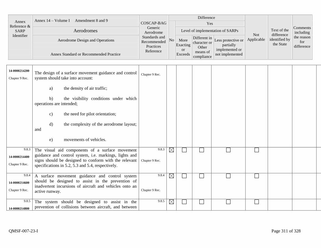
Annex
Reference &
SARP
Identifier
Annex 14 – Volume I Amendment 8 and 9 COSCAP-BAG
Generic
Aerodrome
Standards and
Recommended
Practices
Reference
Difference
Not
Applicable
Text of the
difference
identified by
the State
Comments
including
the reason
for
difference
No
Yes
Aerodromes Level of implementation of SARPs
Aerodrome Design and Operations
Annex Standard or Recommended Practice
More
Exacting
or
Exceeds
Different in
character or
Other
means of
compliance
Less protective or
partially
implemented or
not implemented
QMSF-007-23-I Page 311 of 328
14-0000214200
Chapter 9 Rec.
The design of a surface movement guidance and control
system should take into account:
a) the density of air traffic;
b) the visibility conditions under which
operations are intended;
c) the need for pilot orientation;
d) the complexity of the aerodrome layout;
and
e) movements of vehicles.
Chapter 9 Rec.
9.8.3
14-0000214400
Chapter 9 Rec.
The visual aid components of a surface movement
guidance and control system, i.e. markings, lights and
signs should be designed to conform with the relevant
specifications in 5.2, 5.3 and 5.4, respectively.
9.8.3
Chapter 9 Rec.
9.8.4
14-0000214600
Chapter 9 Rec.
A surface movement guidance and control system
should be designed to assist in the prevention of
inadvertent incursions of aircraft and vehicles onto an
active runway.
9.8.4
Chapter 9 Rec.
9.8.5
14-0000214800
The system should be designed to assist in the
prevention of collisions between aircraft, and between
9.8.5
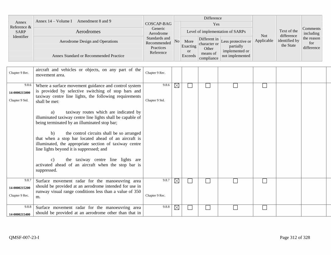
Annex
Reference &
SARP
Identifier
Annex 14 – Volume I Amendment 8 and 9 COSCAP-BAG
Generic
Aerodrome
Standards and
Recommended
Practices
Reference
Difference
Not
Applicable
Text of the
difference
identified by
the State
Comments
including
the reason
for
difference
No
Yes
Aerodromes Level of implementation of SARPs
Aerodrome Design and Operations
Annex Standard or Recommended Practice
More
Exacting
or
Exceeds
Different in
character or
Other
means of
compliance
Less protective or
partially
implemented or
not implemented
QMSF-007-23-I Page 312 of 328
Chapter 9 Rec. aircraft and vehicles or objects, on any part of the
movement area.
Chapter 9 Rec.
9.8.6
14-0000215000
Chapter 9 Std.
Where a surface movement guidance and control system
is provided by selective switching of stop bars and
taxiway centre line lights, the following requirements
shall be met:
a) taxiway routes which are indicated by
illuminated taxiway centre line lights shall be capable of
being terminated by an illuminated stop bar;
b) the control circuits shall be so arranged
that when a stop bar located ahead of an aircraft is
illuminated, the appropriate section of taxiway centre
line lights beyond it is suppressed; and
c) the taxiway centre line lights are
activated ahead of an aircraft when the stop bar is
suppressed.
9.8.6
Chapter 9 Std.
9.8.7
14-0000215200
Chapter 9 Rec.
Surface movement radar for the manoeuvring area
should be provided at an aerodrome intended for use in
runway visual range conditions less than a value of 350
m.
9.8.7
Chapter 9 Rec.
9.8.8
14-0000215400
Surface movement radar for the manoeuvring area
should be provided at an aerodrome other than that in
9.8.8
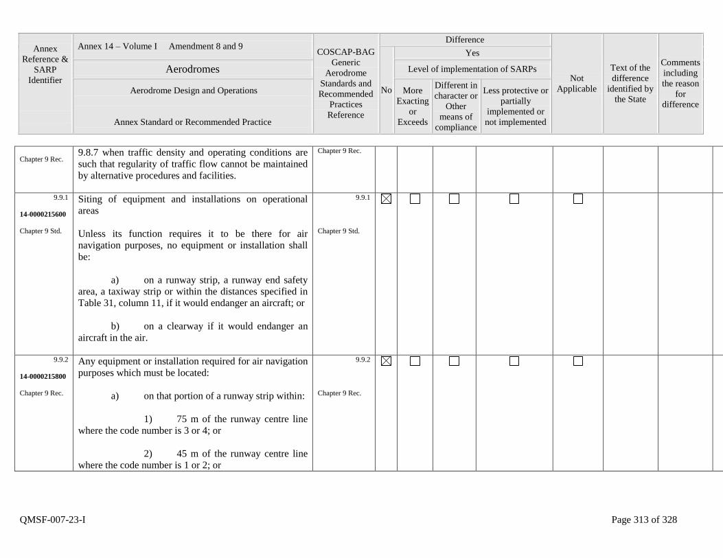
Annex
Reference &
SARP
Identifier
Annex 14 – Volume I Amendment 8 and 9 COSCAP-BAG
Generic
Aerodrome
Standards and
Recommended
Practices
Reference
Difference
Not
Applicable
Text of the
difference
identified by
the State
Comments
including
the reason
for
difference
No
Yes
Aerodromes Level of implementation of SARPs
Aerodrome Design and Operations
Annex Standard or Recommended Practice
More
Exacting
or
Exceeds
Different in
character or
Other
means of
compliance
Less protective or
partially
implemented or
not implemented
QMSF-007-23-I Page 313 of 328
Chapter 9 Rec. 9.8.7 when traffic density and operating conditions are
such that regularity of traffic flow cannot be maintained
by alternative procedures and facilities.
Chapter 9 Rec.
9.9.1
14-0000215600
Chapter 9 Std.
Siting of equipment and installations on operational
areas
Unless its function requires it to be there for air
navigation purposes, no equipment or installation shall
be:
a) on a runway strip, a runway end safety
area, a taxiway strip or within the distances specified in
Table 31, column 11, if it would endanger an aircraft; or
b) on a clearway if it would endanger an
aircraft in the air.
9.9.1
Chapter 9 Std.
9.9.2
14-0000215800
Chapter 9 Rec.
Any equipment or installation required for air navigation
purposes which must be located:
a) on that portion of a runway strip within:
1) 75 m of the runway centre line
where the code number is 3 or 4; or
2) 45 m of the runway centre line
where the code number is 1 or 2; or
9.9.2
Chapter 9 Rec.
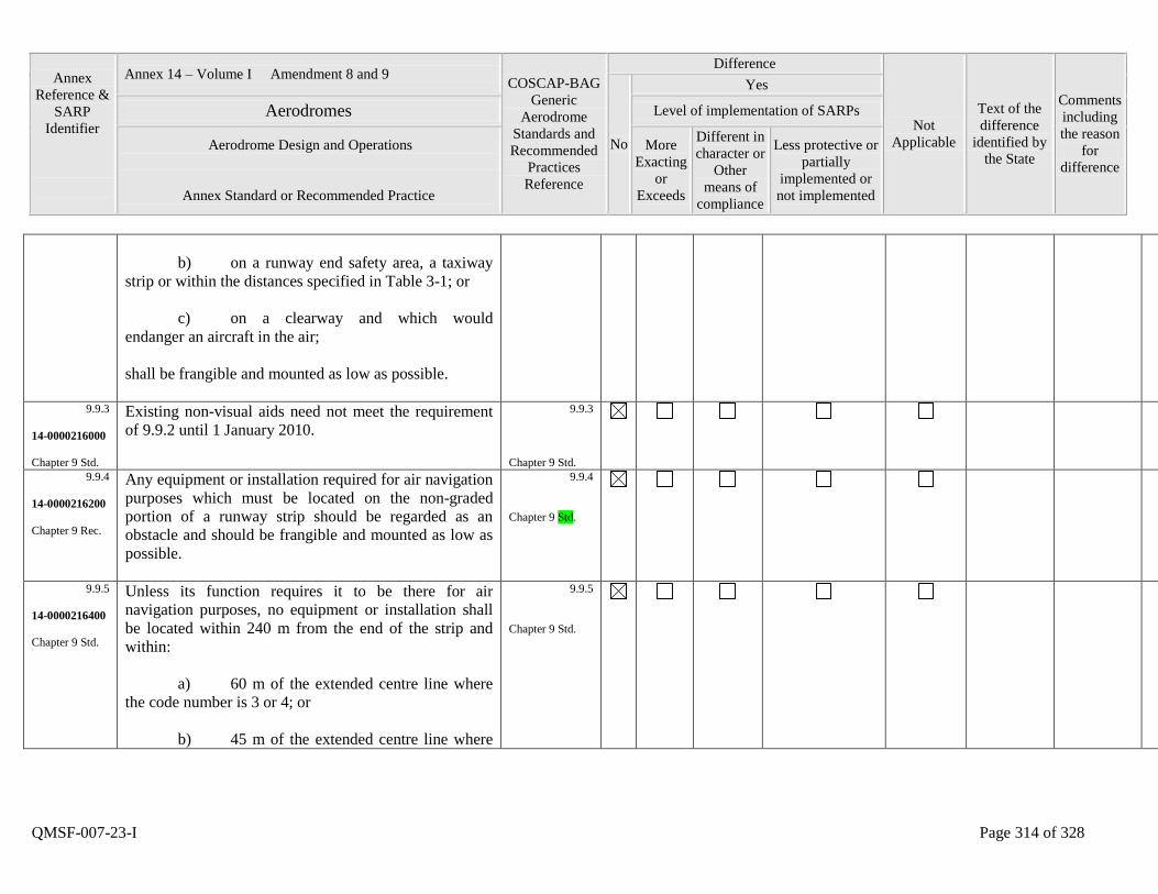
Annex
Reference &
SARP
Identifier
Annex 14 – Volume I Amendment 8 and 9 COSCAP-BAG
Generic
Aerodrome
Standards and
Recommended
Practices
Reference
Difference
Not
Applicable
Text of the
difference
identified by
the State
Comments
including
the reason
for
difference
No
Yes
Aerodromes Level of implementation of SARPs
Aerodrome Design and Operations
Annex Standard or Recommended Practice
More
Exacting
or
Exceeds
Different in
character or
Other
means of
compliance
Less protective or
partially
implemented or
not implemented
QMSF-007-23-I Page 314 of 328
b) on a runway end safety area, a taxiway
strip or within the distances specified in Table 3-1; or
c) on a clearway and which would
endanger an aircraft in the air;
shall be frangible and mounted as low as possible.
9.9.3
14-0000216000
Chapter 9 Std.
Existing non-visual aids need not meet the requirement
of 9.9.2 until 1 January 2010.
9.9.3
Chapter 9 Std.
9.9.4
14-0000216200
Chapter 9 Rec.
Any equipment or installation required for air navigation
purposes which must be located on the non-graded
portion of a runway strip should be regarded as an
obstacle and should be frangible and mounted as low as
possible.
9.9.4
Chapter 9 Std.
9.9.5
14-0000216400
Chapter 9 Std.
Unless its function requires it to be there for air
navigation purposes, no equipment or installation shall
be located within 240 m from the end of the strip and
within:
a) 60 m of the extended centre line where
the code number is 3 or 4; or
b) 45 m of the extended centre line where
9.9.5
Chapter 9 Std.

Annex
Reference &
SARP
Identifier
Annex 14 – Volume I Amendment 8 and 9 COSCAP-BAG
Generic
Aerodrome
Standards and
Recommended
Practices
Reference
Difference
Not
Applicable
Text of the
difference
identified by
the State
Comments
including
the reason
for
difference
No
Yes
Aerodromes Level of implementation of SARPs
Aerodrome Design and Operations
Annex Standard or Recommended Practice
More
Exacting
or
Exceeds
Different in
character or
Other
means of
compliance
Less protective or
partially
implemented or
not implemented
QMSF-007-23-I Page 315 of 328
the code number is 1 or 2;
of a precision approach runway category I, II or III.
9.9.6
14-0000216600
Chapter 9 Std.
Any equipment or installation required for air navigation
purposes which must be located on or near a strip of a
precision approach runway category I, II or III and
which:
a) is situated on that portion of the strip
within 77.5 m of the runway centre line where the code
number is 4 and the code letter is F; or
b) is situated within 240 m from the end of
the strip and within:
1) 60 m of the extended runway
centre line where the code number is 3 or 4; or
2) 45 m of the extended runway
centre line where the code number is 1 or 2; or
c) penetrates the inner approach surface,
the inner transitional surface or the balked landing
surface;
shall be frangible and mounted as low as possible.
9.9.6
Chapter 9 Std.
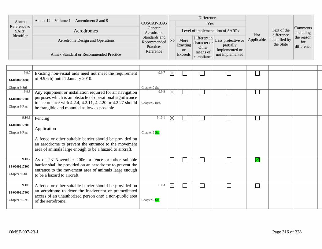
Annex
Reference &
SARP
Identifier
Annex 14 – Volume I Amendment 8 and 9 COSCAP-BAG
Generic
Aerodrome
Standards and
Recommended
Practices
Reference
Difference
Not
Applicable
Text of the
difference
identified by
the State
Comments
including
the reason
for
difference
No
Yes
Aerodromes Level of implementation of SARPs
Aerodrome Design and Operations
Annex Standard or Recommended Practice
More
Exacting
or
Exceeds
Different in
character or
Other
means of
compliance
Less protective or
partially
implemented or
not implemented
QMSF-007-23-I Page 316 of 328
9.9.7
14-0000216800
Chapter 9 Std.
Existing non-visual aids need not meet the requirement
of 9.9.6 b) until 1 January 2010.
9.9.7
Chapter 9 Std.
9.9.8
14-0000217000
Chapter 9 Rec.
Any equipment or installation required for air navigation
purposes which is an obstacle of operational significance
in accordance with 4.2.4, 4.2.11, 4.2.20 or 4.2.27 should
be frangible and mounted as low as possible.
9.9.8
Chapter 9 Rec.
9.10.1
14-0000217200
Chapter 9 Rec.
Fencing
Application
A fence or other suitable barrier should be provided on
an aerodrome to prevent the entrance to the movement
area of animals large enough to be a hazard to aircraft.
9.10.1
Chapter 9 Std.
9.10.2
14-0000217300
Chapter 9 Std.
As of 23 November 2006, a fence or other suitable
barrier shall be provided on an aerodrome to prevent the
entrance to the movement area of animals large enough
to be a hazard to aircraft.
9.10.3
14-0000217400
Chapter 9 Rec.
A fence or other suitable barrier should be provided on
an aerodrome to deter the inadvertent or premeditated
access of an unauthorized person onto a non-public area
of the aerodrome.
9.10.3
Chapter 9 Std.
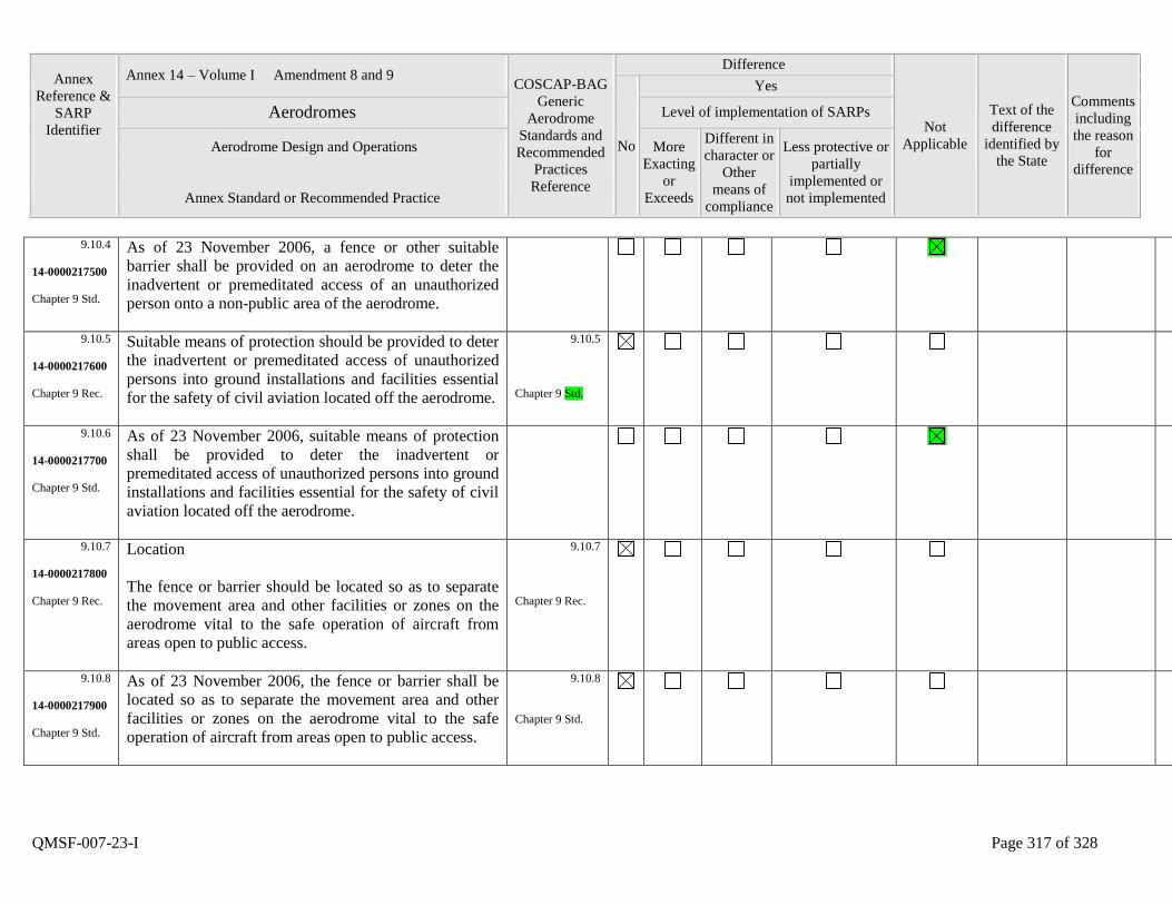
Annex
Reference &
SARP
Identifier
Annex 14 – Volume I Amendment 8 and 9 COSCAP-BAG
Generic
Aerodrome
Standards and
Recommended
Practices
Reference
Difference
Not
Applicable
Text of the
difference
identified by
the State
Comments
including
the reason
for
difference
No
Yes
Aerodromes Level of implementation of SARPs
Aerodrome Design and Operations
Annex Standard or Recommended Practice
More
Exacting
or
Exceeds
Different in
character or
Other
means of
compliance
Less protective or
partially
implemented or
not implemented
QMSF-007-23-I Page 317 of 328
9.10.4
14-0000217500
Chapter 9 Std.
As of 23 November 2006, a fence or other suitable
barrier shall be provided on an aerodrome to deter the
inadvertent or premeditated access of an unauthorized
person onto a non-public area of the aerodrome.
9.10.5
14-0000217600
Chapter 9 Rec.
Suitable means of protection should be provided to deter
the inadvertent or premeditated access of unauthorized
persons into ground installations and facilities essential
for the safety of civil aviation located off the aerodrome.
9.10.5
Chapter 9 Std.
9.10.6
14-0000217700
Chapter 9 Std.
As of 23 November 2006, suitable means of protection
shall be provided to deter the inadvertent or
premeditated access of unauthorized persons into ground
installations and facilities essential for the safety of civil
aviation located off the aerodrome.
9.10.7
14-0000217800
Chapter 9 Rec.
Location
The fence or barrier should be located so as to separate
the movement area and other facilities or zones on the
aerodrome vital to the safe operation of aircraft from
areas open to public access.
9.10.7
Chapter 9 Rec.
9.10.8
14-0000217900
Chapter 9 Std.
As of 23 November 2006, the fence or barrier shall be
located so as to separate the movement area and other
facilities or zones on the aerodrome vital to the safe
operation of aircraft from areas open to public access.
9.10.8
Chapter 9 Std.
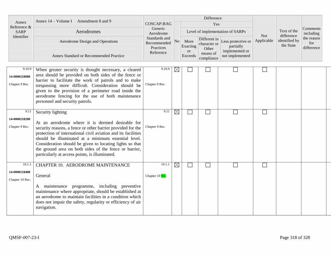
Annex
Reference &
SARP
Identifier
Annex 14 – Volume I Amendment 8 and 9 COSCAP-BAG
Generic
Aerodrome
Standards and
Recommended
Practices
Reference
Difference
Not
Applicable
Text of the
difference
identified by
the State
Comments
including
the reason
for
difference
No
Yes
Aerodromes Level of implementation of SARPs
Aerodrome Design and Operations
Annex Standard or Recommended Practice
More
Exacting
or
Exceeds
Different in
character or
Other
means of
compliance
Less protective or
partially
implemented or
not implemented
QMSF-007-23-I Page 318 of 328
9.10.9
14-0000218000
Chapter 9 Rec.
When greater security is thought necessary, a cleared
area should be provided on both sides of the fence or
barrier to facilitate the work of patrols and to make
trespassing more difficult. Consideration should be
given to the provision of a perimeter road inside the
aerodrome fencing for the use of both maintenance
personnel and security patrols.
9.10.9
Chapter 9 Rec.
9.11
14-0000218200
Chapter 9 Rec.
Security lighting
At an aerodrome where it is deemed desirable for
security reasons, a fence or other barrier provided for the
protection of international civil aviation and its facilities
should be illuminated at a minimum essential level.
Consideration should be given to locating lights so that
the ground area on both sides of the fence or barrier,
particularly at access points, is illuminated.
9.11
Chapter 9 Rec.
10.1.1
14-0000218400
Chapter 10 Rec.
CHAPTER 10. AERODROME MAINTENANCE
General
A maintenance programme, including preventive
maintenance where appropriate, should be established at
an aerodrome to maintain facilities in a condition which
does not impair the safety, regularity or efficiency of air
navigation.
10.1.1
Chapter 10 Std.
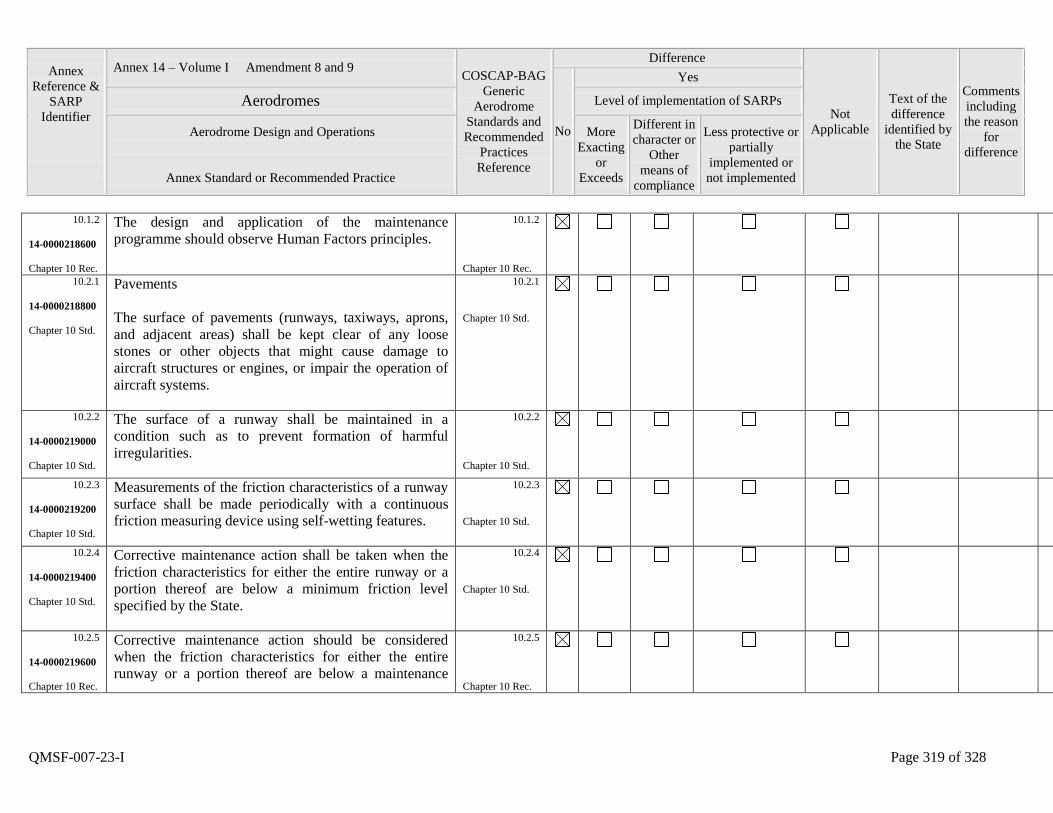
Annex
Reference &
SARP
Identifier
Annex 14 – Volume I Amendment 8 and 9 COSCAP-BAG
Generic
Aerodrome
Standards and
Recommended
Practices
Reference
Difference
Not
Applicable
Text of the
difference
identified by
the State
Comments
including
the reason
for
difference
No
Yes
Aerodromes Level of implementation of SARPs
Aerodrome Design and Operations
Annex Standard or Recommended Practice
More
Exacting
or
Exceeds
Different in
character or
Other
means of
compliance
Less protective or
partially
implemented or
not implemented
QMSF-007-23-I Page 319 of 328
10.1.2
14-0000218600
Chapter 10 Rec.
The design and application of the maintenance
programme should observe Human Factors principles.
10.1.2
Chapter 10 Rec.
10.2.1
14-0000218800
Chapter 10 Std.
Pavements
The surface of pavements (runways, taxiways, aprons,
and adjacent areas) shall be kept clear of any loose
stones or other objects that might cause damage to
aircraft structures or engines, or impair the operation of
aircraft systems.
10.2.1
Chapter 10 Std.
10.2.2
14-0000219000
Chapter 10 Std.
The surface of a runway shall be maintained in a
condition such as to prevent formation of harmful
irregularities.
10.2.2
Chapter 10 Std.
10.2.3
14-0000219200
Chapter 10 Std.
Measurements of the friction characteristics of a runway
surface shall be made periodically with a continuous
friction measuring device using self-wetting features.
10.2.3
Chapter 10 Std.
10.2.4
14-0000219400
Chapter 10 Std.
Corrective maintenance action shall be taken when the
friction characteristics for either the entire runway or a
portion thereof are below a minimum friction level
specified by the State.
10.2.4
Chapter 10 Std.
10.2.5
14-0000219600
Chapter 10 Rec.
Corrective maintenance action should be considered
when the friction characteristics for either the entire
runway or a portion thereof are below a maintenance
10.2.5
Chapter 10 Rec.
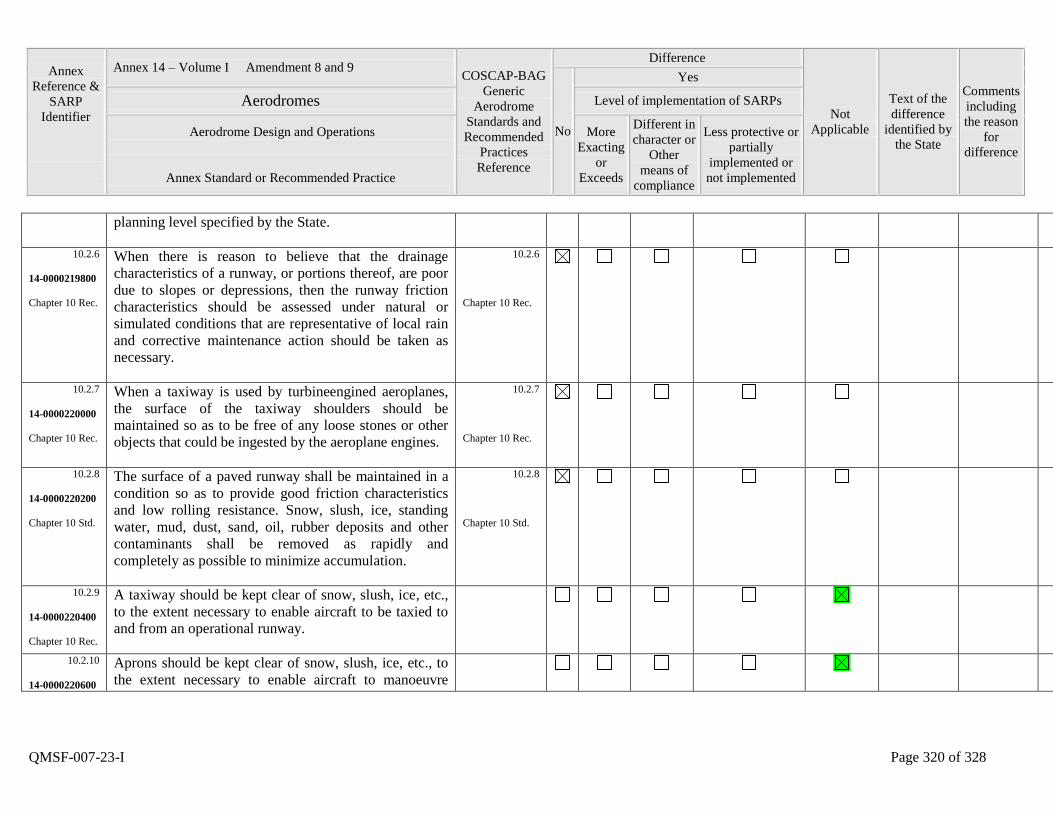
Annex
Reference &
SARP
Identifier
Annex 14 – Volume I Amendment 8 and 9 COSCAP-BAG
Generic
Aerodrome
Standards and
Recommended
Practices
Reference
Difference
Not
Applicable
Text of the
difference
identified by
the State
Comments
including
the reason
for
difference
No
Yes
Aerodromes Level of implementation of SARPs
Aerodrome Design and Operations
Annex Standard or Recommended Practice
More
Exacting
or
Exceeds
Different in
character or
Other
means of
compliance
Less protective or
partially
implemented or
not implemented
QMSF-007-23-I Page 320 of 328
planning level specified by the State.
10.2.6
14-0000219800
Chapter 10 Rec.
When there is reason to believe that the drainage
characteristics of a runway, or portions thereof, are poor
due to slopes or depressions, then the runway friction
characteristics should be assessed under natural or
simulated conditions that are representative of local rain
and corrective maintenance action should be taken as
necessary.
10.2.6
Chapter 10 Rec.
10.2.7
14-0000220000
Chapter 10 Rec.
When a taxiway is used by turbineengined aeroplanes,
the surface of the taxiway shoulders should be
maintained so as to be free of any loose stones or other
objects that could be ingested by the aeroplane engines.
10.2.7
Chapter 10 Rec.
10.2.8
14-0000220200
Chapter 10 Std.
The surface of a paved runway shall be maintained in a
condition so as to provide good friction characteristics
and low rolling resistance. Snow, slush, ice, standing
water, mud, dust, sand, oil, rubber deposits and other
contaminants shall be removed as rapidly and
completely as possible to minimize accumulation.
10.2.8
Chapter 10 Std.
10.2.9
14-0000220400
Chapter 10 Rec.
A taxiway should be kept clear of snow, slush, ice, etc.,
to the extent necessary to enable aircraft to be taxied to
and from an operational runway.
10.2.10
14-0000220600
Aprons should be kept clear of snow, slush, ice, etc., to
the extent necessary to enable aircraft to manoeuvre
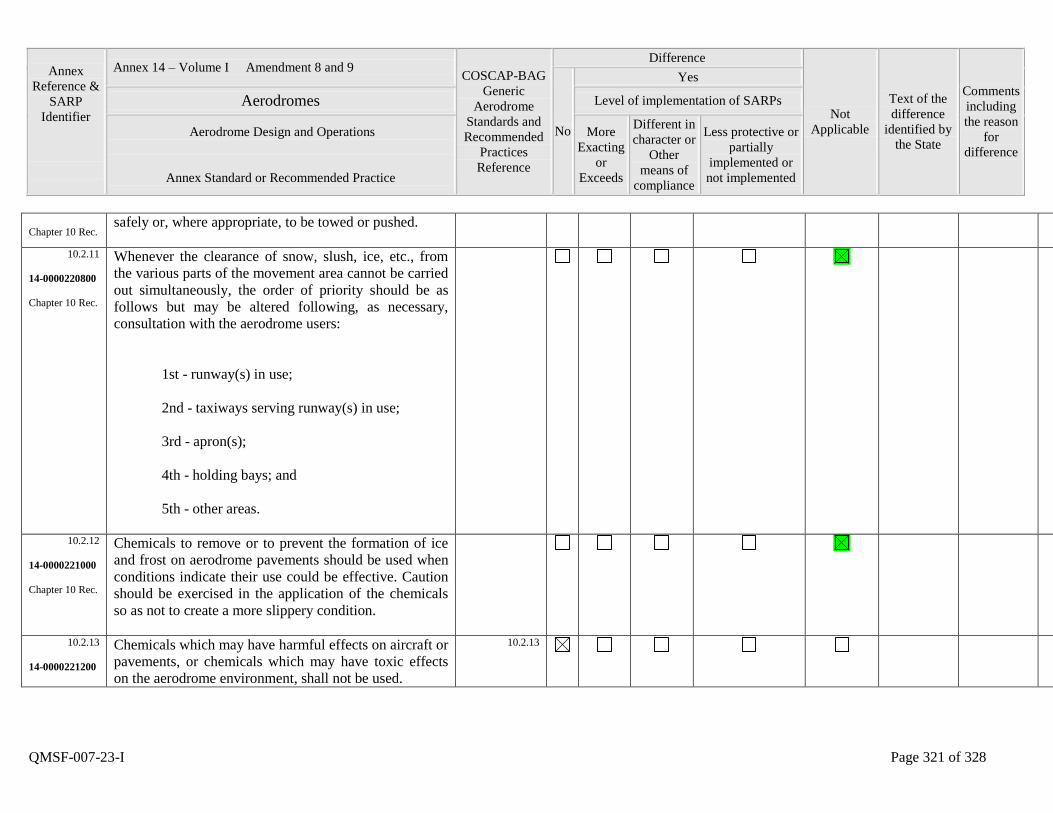
Annex
Reference &
SARP
Identifier
Annex 14 – Volume I Amendment 8 and 9 COSCAP-BAG
Generic
Aerodrome
Standards and
Recommended
Practices
Reference
Difference
Not
Applicable
Text of the
difference
identified by
the State
Comments
including
the reason
for
difference
No
Yes
Aerodromes Level of implementation of SARPs
Aerodrome Design and Operations
Annex Standard or Recommended Practice
More
Exacting
or
Exceeds
Different in
character or
Other
means of
compliance
Less protective or
partially
implemented or
not implemented
QMSF-007-23-I Page 321 of 328
Chapter 10 Rec. safely or, where appropriate, to be towed or pushed.
10.2.11
14-0000220800
Chapter 10 Rec.
Whenever the clearance of snow, slush, ice, etc., from
the various parts of the movement area cannot be carried
out simultaneously, the order of priority should be as
follows but may be altered following, as necessary,
consultation with the aerodrome users:
1st - runway(s) in use;
2nd - taxiways serving runway(s) in use;
3rd - apron(s);
4th - holding bays; and
5th - other areas.
10.2.12
14-0000221000
Chapter 10 Rec.
Chemicals to remove or to prevent the formation of ice
and frost on aerodrome pavements should be used when
conditions indicate their use could be effective. Caution
should be exercised in the application of the chemicals
so as not to create a more slippery condition.
10.2.13
14-0000221200
Chemicals which may have harmful effects on aircraft or
pavements, or chemicals which may have toxic effects
on the aerodrome environment, shall not be used.
10.2.13
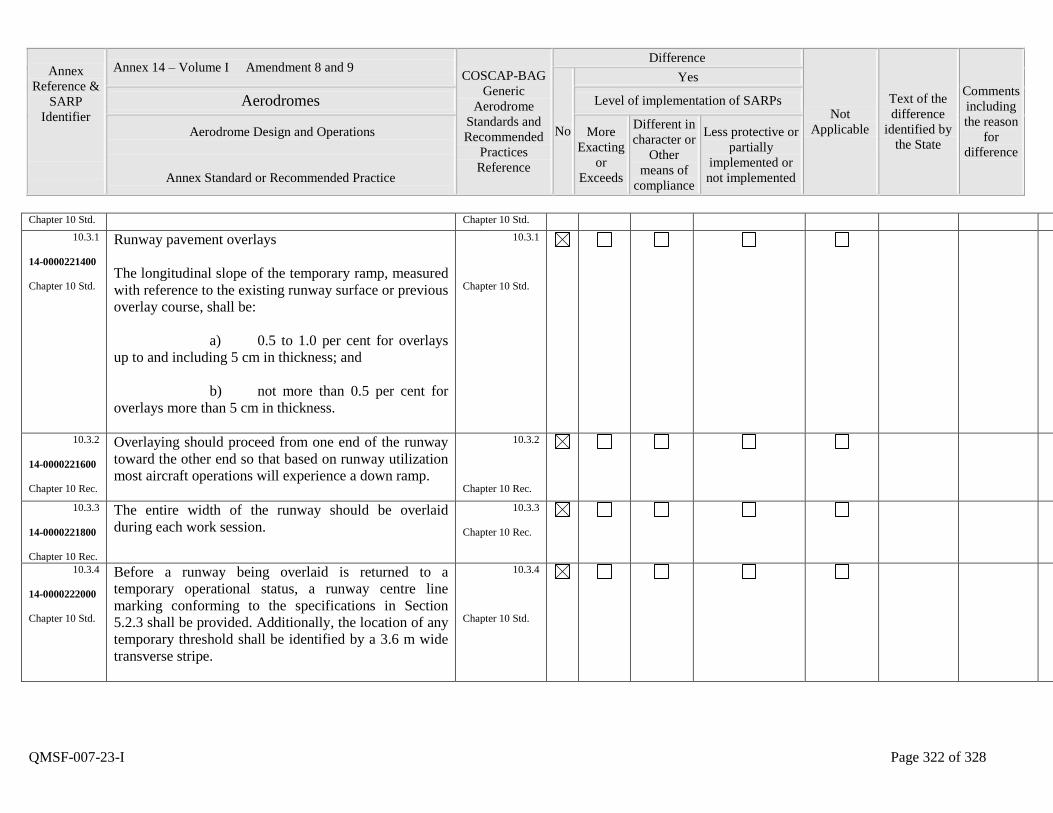
Annex
Reference &
SARP
Identifier
Annex 14 – Volume I Amendment 8 and 9 COSCAP-BAG
Generic
Aerodrome
Standards and
Recommended
Practices
Reference
Difference
Not
Applicable
Text of the
difference
identified by
the State
Comments
including
the reason
for
difference
No
Yes
Aerodromes Level of implementation of SARPs
Aerodrome Design and Operations
Annex Standard or Recommended Practice
More
Exacting
or
Exceeds
Different in
character or
Other
means of
compliance
Less protective or
partially
implemented or
not implemented
QMSF-007-23-I Page 322 of 328
Chapter 10 Std. Chapter 10 Std.
10.3.1
14-0000221400
Chapter 10 Std.
Runway pavement overlays
The longitudinal slope of the temporary ramp, measured
with reference to the existing runway surface or previous
overlay course, shall be:
a) 0.5 to 1.0 per cent for overlays
up to and including 5 cm in thickness; and
b) not more than 0.5 per cent for
overlays more than 5 cm in thickness.
10.3.1
Chapter 10 Std.
10.3.2
14-0000221600
Chapter 10 Rec.
Overlaying should proceed from one end of the runway
toward the other end so that based on runway utilization
most aircraft operations will experience a down ramp.
10.3.2
Chapter 10 Rec.
10.3.3
14-0000221800
Chapter 10 Rec.
The entire width of the runway should be overlaid
during each work session.
10.3.3
Chapter 10 Rec.
10.3.4
14-0000222000
Chapter 10 Std.
Before a runway being overlaid is returned to a
temporary operational status, a runway centre line
marking conforming to the specifications in Section
5.2.3 shall be provided. Additionally, the location of any
temporary threshold shall be identified by a 3.6 m wide
transverse stripe.
10.3.4
Chapter 10 Std.
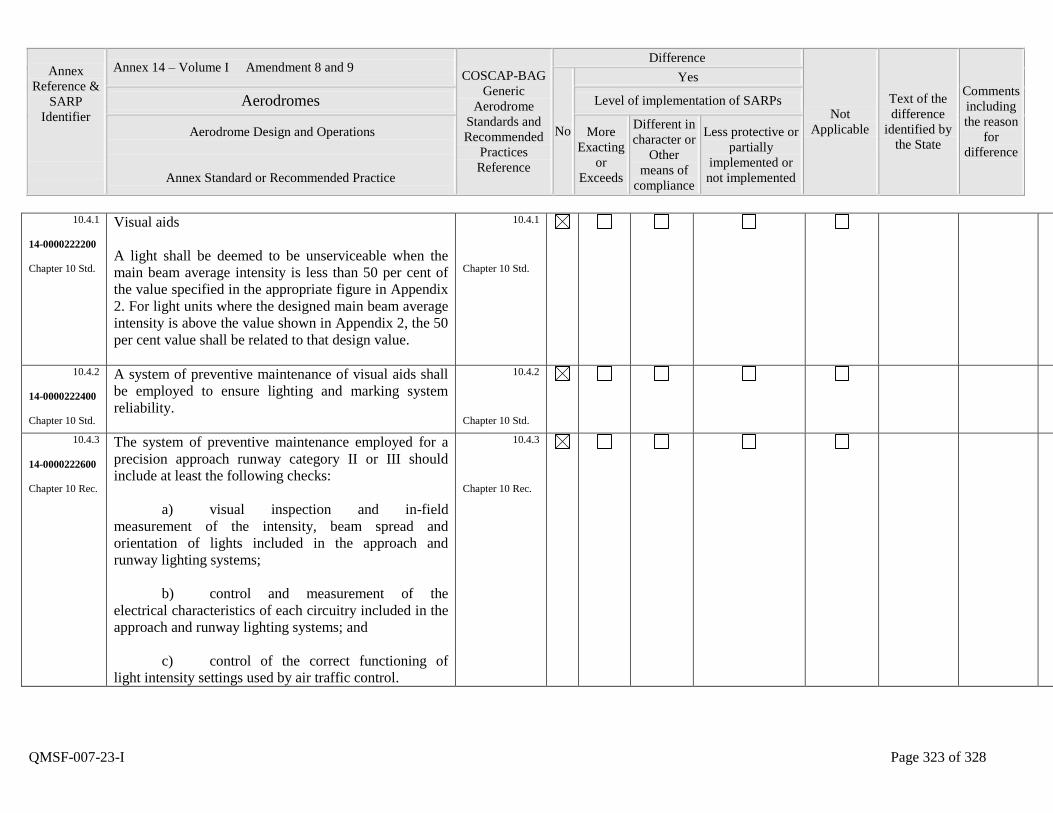
Annex
Reference &
SARP
Identifier
Annex 14 – Volume I Amendment 8 and 9 COSCAP-BAG
Generic
Aerodrome
Standards and
Recommended
Practices
Reference
Difference
Not
Applicable
Text of the
difference
identified by
the State
Comments
including
the reason
for
difference
No
Yes
Aerodromes Level of implementation of SARPs
Aerodrome Design and Operations
Annex Standard or Recommended Practice
More
Exacting
or
Exceeds
Different in
character or
Other
means of
compliance
Less protective or
partially
implemented or
not implemented
QMSF-007-23-I Page 323 of 328
10.4.1
14-0000222200
Chapter 10 Std.
Visual aids
A light shall be deemed to be unserviceable when the
main beam average intensity is less than 50 per cent of
the value specified in the appropriate figure in Appendix
2. For light units where the designed main beam average
intensity is above the value shown in Appendix 2, the 50
per cent value shall be related to that design value.
10.4.1
Chapter 10 Std.
10.4.2
14-0000222400
Chapter 10 Std.
A system of preventive maintenance of visual aids shall
be employed to ensure lighting and marking system
reliability.
10.4.2
Chapter 10 Std.
10.4.3
14-0000222600
Chapter 10 Rec.
The system of preventive maintenance employed for a
precision approach runway category II or III should
include at least the following checks:
a) visual inspection and in-field
measurement of the intensity, beam spread and
orientation of lights included in the approach and
runway lighting systems;
b) control and measurement of the
electrical characteristics of each circuitry included in the
approach and runway lighting systems; and
c) control of the correct functioning of
light intensity settings used by air traffic control.
10.4.3
Chapter 10 Rec.
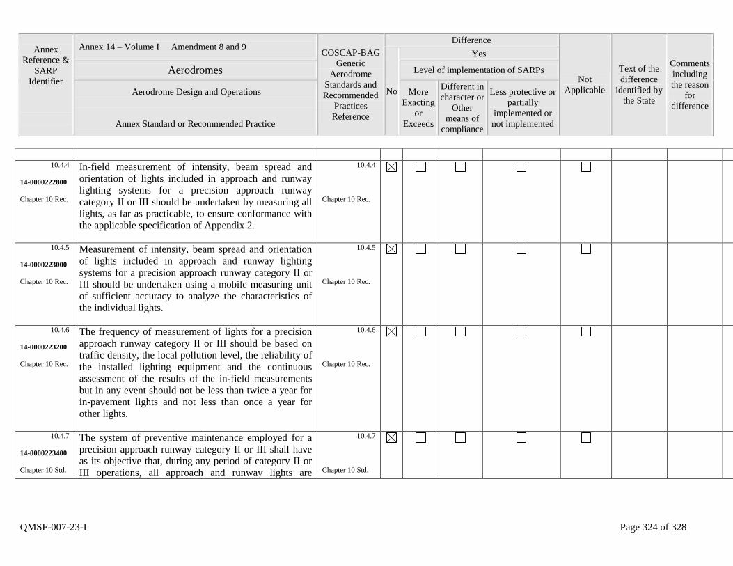
Annex
Reference &
SARP
Identifier
Annex 14 – Volume I Amendment 8 and 9 COSCAP-BAG
Generic
Aerodrome
Standards and
Recommended
Practices
Reference
Difference
Not
Applicable
Text of the
difference
identified by
the State
Comments
including
the reason
for
difference
No
Yes
Aerodromes Level of implementation of SARPs
Aerodrome Design and Operations
Annex Standard or Recommended Practice
More
Exacting
or
Exceeds
Different in
character or
Other
means of
compliance
Less protective or
partially
implemented or
not implemented
QMSF-007-23-I Page 324 of 328
10.4.4
14-0000222800
Chapter 10 Rec.
In-field measurement of intensity, beam spread and
orientation of lights included in approach and runway
lighting systems for a precision approach runway
category II or III should be undertaken by measuring all
lights, as far as practicable, to ensure conformance with
the applicable specification of Appendix 2.
10.4.4
Chapter 10 Rec.
10.4.5
14-0000223000
Chapter 10 Rec.
Measurement of intensity, beam spread and orientation
of lights included in approach and runway lighting
systems for a precision approach runway category II or
III should be undertaken using a mobile measuring unit
of sufficient accuracy to analyze the characteristics of
the individual lights.
10.4.5
Chapter 10 Rec.
10.4.6
14-0000223200
Chapter 10 Rec.
The frequency of measurement of lights for a precision
approach runway category II or III should be based on
traffic density, the local pollution level, the reliability of
the installed lighting equipment and the continuous
assessment of the results of the in-field measurements
but in any event should not be less than twice a year for
in-pavement lights and not less than once a year for
other lights.
10.4.6
Chapter 10 Rec.
10.4.7
14-0000223400
Chapter 10 Std.
The system of preventive maintenance employed for a
precision approach runway category II or III shall have
as its objective that, during any period of category II or
III operations, all approach and runway lights are
10.4.7
Chapter 10 Std.
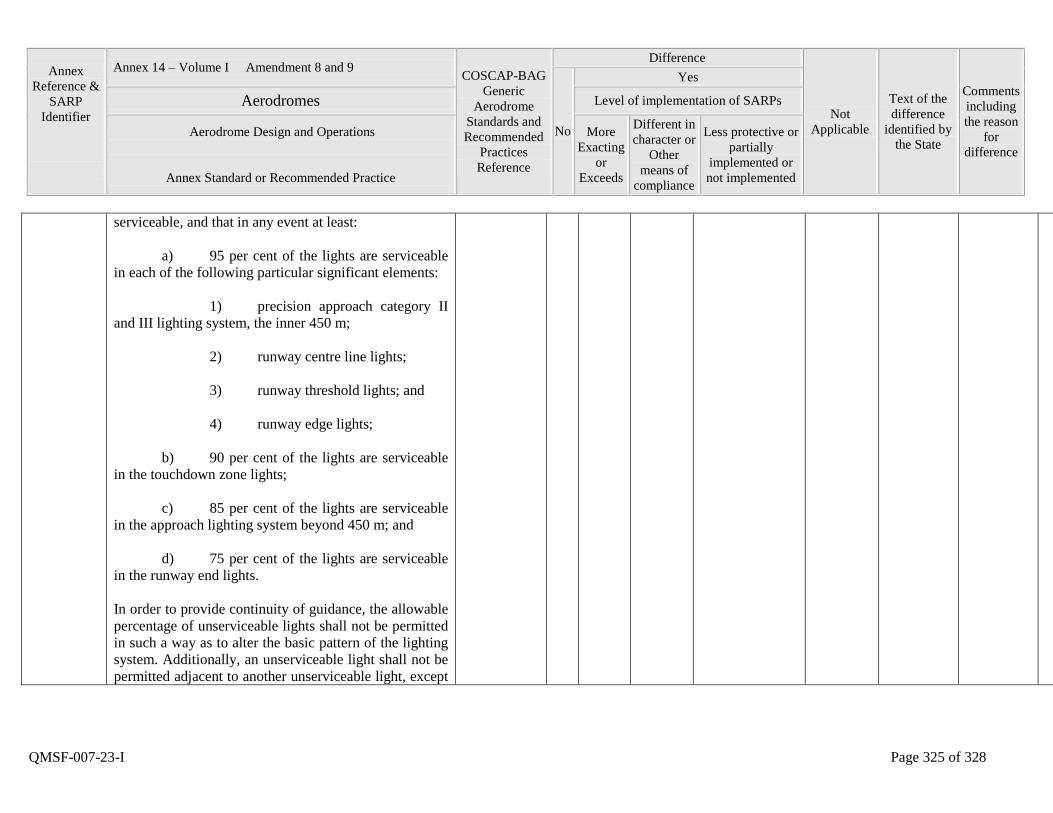
Annex
Reference &
SARP
Identifier
Annex 14 – Volume I Amendment 8 and 9 COSCAP-BAG
Generic
Aerodrome
Standards and
Recommended
Practices
Reference
Difference
Not
Applicable
Text of the
difference
identified by
the State
Comments
including
the reason
for
difference
No
Yes
Aerodromes Level of implementation of SARPs
Aerodrome Design and Operations
Annex Standard or Recommended Practice
More
Exacting
or
Exceeds
Different in
character or
Other
means of
compliance
Less protective or
partially
implemented or
not implemented
QMSF-007-23-I Page 325 of 328
serviceable, and that in any event at least:
a) 95 per cent of the lights are serviceable
in each of the following particular significant elements:
1) precision approach category II
and III lighting system, the inner 450 m;
2) runway centre line lights;
3) runway threshold lights; and
4) runway edge lights;
b) 90 per cent of the lights are serviceable
in the touchdown zone lights;
c) 85 per cent of the lights are serviceable
in the approach lighting system beyond 450 m; and
d) 75 per cent of the lights are serviceable
in the runway end lights.
In order to provide continuity of guidance, the allowable
percentage of unserviceable lights shall not be permitted
in such a way as to alter the basic pattern of the lighting
system. Additionally, an unserviceable light shall not be
permitted adjacent to another unserviceable light, except
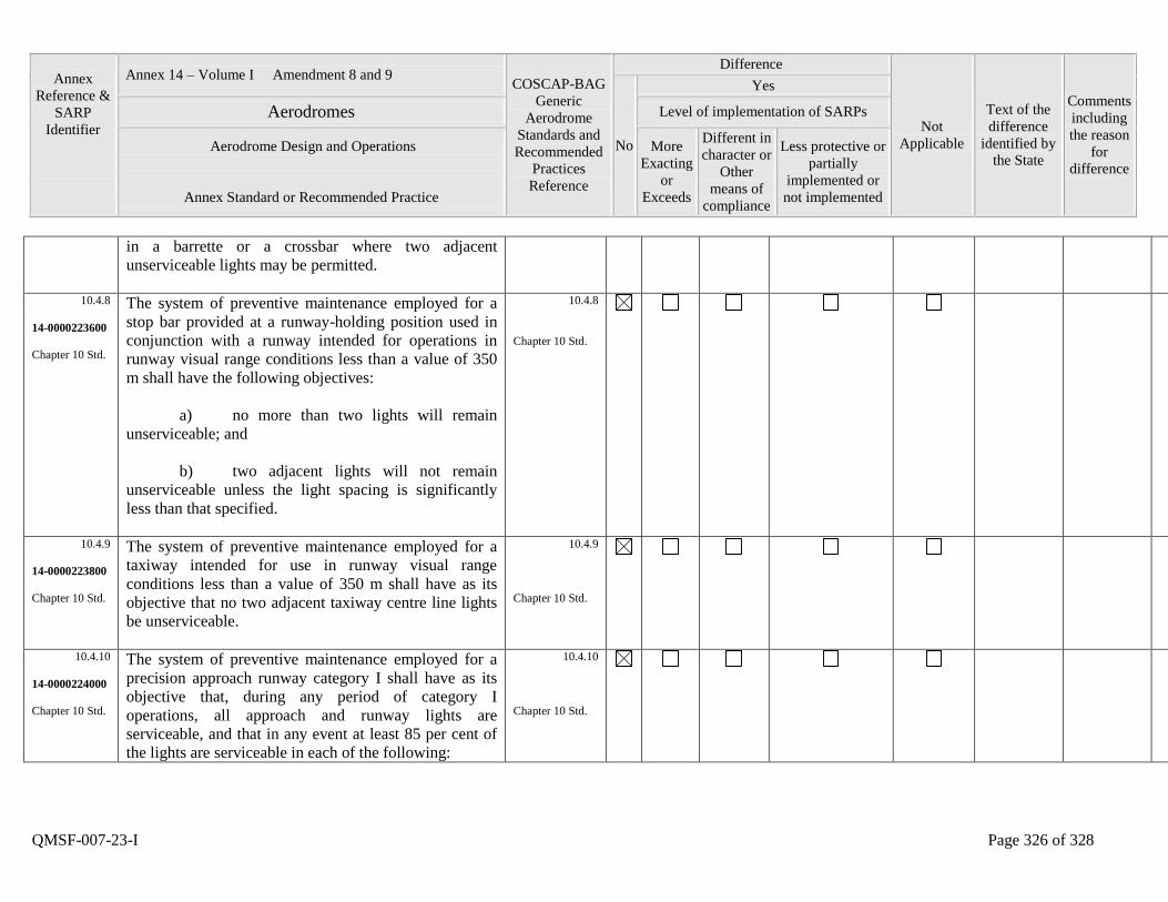
Annex
Reference &
SARP
Identifier
Annex 14 – Volume I Amendment 8 and 9 COSCAP-BAG
Generic
Aerodrome
Standards and
Recommended
Practices
Reference
Difference
Not
Applicable
Text of the
difference
identified by
the State
Comments
including
the reason
for
difference
No
Yes
Aerodromes Level of implementation of SARPs
Aerodrome Design and Operations
Annex Standard or Recommended Practice
More
Exacting
or
Exceeds
Different in
character or
Other
means of
compliance
Less protective or
partially
implemented or
not implemented
QMSF-007-23-I Page 326 of 328
in a barrette or a crossbar where two adjacent
unserviceable lights may be permitted.
10.4.8
14-0000223600
Chapter 10 Std.
The system of preventive maintenance employed for a
stop bar provided at a runway-holding position used in
conjunction with a runway intended for operations in
runway visual range conditions less than a value of 350
m shall have the following objectives:
a) no more than two lights will remain
unserviceable; and
b) two adjacent lights will not remain
unserviceable unless the light spacing is significantly
less than that specified.
10.4.8
Chapter 10 Std.
10.4.9
14-0000223800
Chapter 10 Std.
The system of preventive maintenance employed for a
taxiway intended for use in runway visual range
conditions less than a value of 350 m shall have as its
objective that no two adjacent taxiway centre line lights
be unserviceable.
10.4.9
Chapter 10 Std.
10.4.10
14-0000224000
Chapter 10 Std.
The system of preventive maintenance employed for a
precision approach runway category I shall have as its
objective that, during any period of category I
operations, all approach and runway lights are
serviceable, and that in any event at least 85 per cent of
the lights are serviceable in each of the following:
10.4.10
Chapter 10 Std.
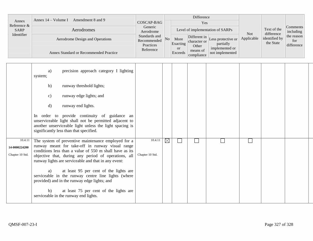
Annex
Reference &
SARP
Identifier
Annex 14 – Volume I Amendment 8 and 9 COSCAP-BAG
Generic
Aerodrome
Standards and
Recommended
Practices
Reference
Difference
Not
Applicable
Text of the
difference
identified by
the State
Comments
including
the reason
for
difference
No
Yes
Aerodromes Level of implementation of SARPs
Aerodrome Design and Operations
Annex Standard or Recommended Practice
More
Exacting
or
Exceeds
Different in
character or
Other
means of
compliance
Less protective or
partially
implemented or
not implemented
QMSF-007-23-I Page 327 of 328
a) precision approach category I lighting
system;
b) runway threshold lights;
c) runway edge lights; and
d) runway end lights.
In order to provide continuity of guidance an
unserviceable light shall not be permitted adjacent to
another unserviceable light unless the light spacing is
significantly less than that specified.
10.4.11
14-0000224200
Chapter 10 Std.
The system of preventive maintenance employed for a
runway meant for take-off in runway visual range
conditions less than a value of 550 m shall have as its
objective that, during any period of operations, all
runway lights are serviceable and that in any event:
a) at least 95 per cent of the lights are
serviceable in the runway centre line lights (where
provided) and in the runway edge lights; and
b) at least 75 per cent of the lights are
serviceable in the runway end lights.
10.4.11
Chapter 10 Std.
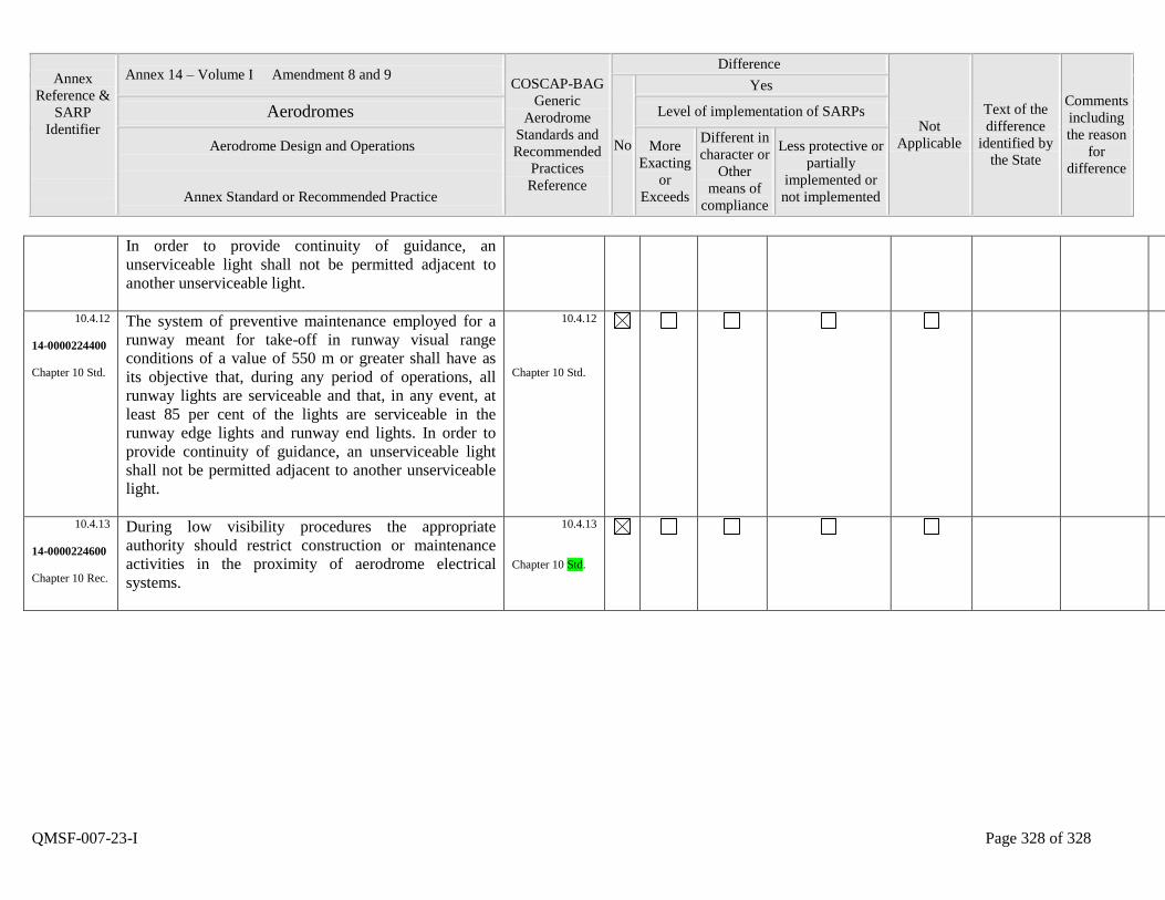
Annex
Reference &
SARP
Identifier
Annex 14 – Volume I Amendment 8 and 9 COSCAP-BAG
Generic
Aerodrome
Standards and
Recommended
Practices
Reference
Difference
Not
Applicable
Text of the
difference
identified by
the State
Comments
including
the reason
for
difference
No
Yes
Aerodromes Level of implementation of SARPs
Aerodrome Design and Operations
Annex Standard or Recommended Practice
More
Exacting
or
Exceeds
Different in
character or
Other
means of
compliance
Less protective or
partially
implemented or
not implemented
QMSF-007-23-I Page 328 of 328
In order to provide continuity of guidance, an
unserviceable light shall not be permitted adjacent to
another unserviceable light.
10.4.12
14-0000224400
Chapter 10 Std.
The system of preventive maintenance employed for a
runway meant for take-off in runway visual range
conditions of a value of 550 m or greater shall have as
its objective that, during any period of operations, all
runway lights are serviceable and that, in any event, at
least 85 per cent of the lights are serviceable in the
runway edge lights and runway end lights. In order to
provide continuity of guidance, an unserviceable light
shall not be permitted adjacent to another unserviceable
light.
10.4.12
Chapter 10 Std.
10.4.13
14-0000224600
Chapter 10 Rec.
During low visibility procedures the appropriate
authority should restrict construction or maintenance
activities in the proximity of aerodrome electrical
systems.
10.4.13
Chapter 10 Std.


![€¦ · Web viewSafety Oversight Compliance Checklist. This document contains a safety oversight compliance checklist for Annex 1 - Personnel Licensing [Amendment 168]. The Compliance](https://img.dokumen.tips/doc/110x75/5e837faa061c125b6174c87b/web-view-safety-oversight-compliance-checklist-this-document-contains-a-safety.jpg)


![(Unit Environmental Compliance Officer [UECO] Oversight) Training](https://img.dokumen.tips/doc/110x75/586a48c51a28ab677d8bf6b0/unit-environmental-compliance-officer-ueco-oversight-training.jpg)


