Embed Size (px)
Citation preview
SafeT
Work package 1 “Current state of practice”
D1 report
Current practice in tunnel safety
Version: April 2005 Author: I.J.M. Trijssenaar-Buhre (TNO)
W.W.R. Koch (TNO) T. Wiersma (TNO)
C. Ramirez (SICE) Supervisor: M. Molag (TNO)

Workpackage 1 “Current state of practice” SafeT
2
Table of contents D1 Report
The D1 report consists of 4 reports on different aspects of tunnels safety:
D1.1 State of the art Safety Approach, Safety Management Systems, and Risk Assessment D1.2 State of the art Detection, Prevention and Traffic Management D1.3 State of the art Consequence Mitigation D1.4 State of the art Post Accident Investigation and Evaluation
Workpackage 1 “Current state of practice” SafeT
3
D1.1 State of the art Safety Approach, Safety Management Systems, and Risk Assessment
1. Objective of the state of the art reports.................................................................................... 3
2. Safety chain approach.............................................................................................................. 4
3. Safety Management ................................................................................................................. 5 3.1 Introduction .............................................................................................................. 5 3.2 General management ................................................................................................ 6 3.3 Design for safe operation: prescriptive guidelines and risk assessment................... 7
3.3.1 Introduction....................................................................................................7 3.3.2 Prescriptive guidelines...................................................................................7 3.3.3 Risk assessment .............................................................................................8
3.4 Contractor safety .................................................................................................... 14 3.5 Safety training ........................................................................................................ 14 3.6 Planning for emergency response........................................................................... 15 3.7 Operation ................................................................................................................ 15 3.8 Inspection ............................................................................................................... 16 3.9 Maintenance ........................................................................................................... 16 3.10 Accident analysis.................................................................................................... 16 3.11 Safety audits ........................................................................................................... 17
4. References …………………………………………………………………………………...21
Workpackage 1 “Current state of practice” SafeT
4
D1.2 State of the art Detection, Prevention and Traffic Management
1. Abbreviations.......................................................................................................................... 3
2. Introduction............................................................................................................................. 4
3. Technical measures................................................................................................................. 6 3.1 Overview of technical measures............................................................................ 11
4. Management of information by tunnel operators.................................................................. 14
5. Incident detection in EU member states ............................................................................... 16
6. Traffic management.............................................................................................................. 17
7. Traffic management in EU member states............................................................................ 19
8. Equipment for detection, prevention and traffic management.............................................. 21 8.1 Introduction ........................................................................................................... 21 8.2 Tunnel systems ...................................................................................................... 22 8.3 Traffic signing ....................................................................................................... 25 8.4 Monitoring systems (CCTV and Automatic Incident Detection Systems) ........... 26 8.5 CCTV .................................................................................................................... 26 8.6 Automatic Incident Detection Systems ................................................................. 27 8.7 Emergency phones ................................................................................................ 31 8.8 Traffic Management Equipment............................................................................ 32 8.9 Integration aspects, the experience in Spain.......................................................... 33 8.10 Exploitation aspects............................................................................................... 36 8.11 Conclusions ........................................................................................................... 36
9. Discussion............................................................................................................................. 38
10. References............................................................................................................................. 39
Workpackage 1 “Current state of practice” SafeT
5
D1.3 State of the art Consequence Mitigation
1. Introduction.............................................................................................................................. 3 1.1 Scope of Task 1.3 ..................................................................................................... 3 1.2 What is consequence mitigation? ............................................................................. 4
2. Evacuation / intervention management.................................................................................... 6 2.1 Process analysis of incident management, self-rescue and emergency operation
in tunnels .................................................................................................................. 6 2.1.1 Incident management................................................................................. 6 2.1.2 Self-rescue process .................................................................................... 7 2.1.3 Emergency operation................................................................................. 8
2.2 Discussion: from process analysis to guidelines .................................................... 13
3. Training of operators and rescue personnel ........................................................................... 14 3.1 GAMMA-EC.......................................................................................................... 14
3.1.1 Context .................................................................................................... 14 3.1.2 Goal ......................................................................................................... 14 3.1.3 Results ..................................................................................................... 14
3.2 Demonstrator of GATE training programme ......................................................... 15 3.3 Virtual fires ............................................................................................................ 15 3.4 ADMS .................................................................................................................... 15
4. Technical measures................................................................................................................ 17 4.1 Introduction ............................................................................................................ 17 4.2 Consequence mitigating measures in stage II: “development of the accident”...... 17 4.3 Consequence mitigating measures in stage III: “Detection” .................................. 18 4.4 Consequence mitigating measures in stage IV: “Egress”....................................... 18 4.5 Consequence mitigating measures in stage V: “Emergency response”.................. 19 4.6 Overview of technical measures............................................................................. 19 4.7 Discussion .............................................................................................................. 21
5. References.............................................................................................................................. 23
Workpackage 1 “Current state of practice” SafeT
6
D1.4 State of the art Post Accident Investigation and Evaluation
1. Introduction............................................................................................................................. 3
2. Types of investigations ........................................................................................................... 4
3. General accident investigation approach ................................................................................ 5
4. Consequences taken from the Mont Blanc and Tauern tunnel disasters................................. 8
5. Post accident investigation and evaluation according to the EU directive ........................... 10
6. Conclusion /discussion ......................................................................................................... 11
7. References............................................................................................................................. 12
SafeT
Work package 1
D1.1 report
State of the art report on Safety Approach, Safety Management Systems, and risk assessment
Version: April 2005 Author: T. Wiersma I.J.M. Trijssenaar-Buhre
State of the art report on Safety Approach, Safety Management Systems, and risk assessment SafeT
2
Table of contents
1. Objective of the state of the art reports ................................................................................... 3
2. Introduction............................................................................................................................. 4
3. Safety chain approach ............................................................................................................. 5
4. Safety Management ................................................................................................................ 6 4.1 Introduction ............................................................................................................. 6 4.2 General management ............................................................................................... 7 4.3 Design for safe operation: prescriptive guidelines and risk assessment.................. 8
4.3.1 Introduction .............................................................................................. 8 4.3.2 Prescriptive guidelines.............................................................................. 8 4.3.3 Risk assessment ........................................................................................ 9
4.4 Contractor safety ................................................................................................... 15 4.5 Safety training ....................................................................................................... 15 4.6 Planning for emergency response.......................................................................... 16 4.7 Operation ............................................................................................................... 16 4.8 Inspection .............................................................................................................. 17 4.9 Maintenance .......................................................................................................... 17 4.10 Accident analysis................................................................................................... 18 4.11 Safety audits .......................................................................................................... 18
5. References............................................................................................................................. 22
Appendix: Summary of safety approaches........................................................................................... 24
State of the art report on Safety Approach, Safety Management Systems, and risk assessment SafeT
3
1 Objective of the state of the art reports
The objective of Workpackage 1 is to describe the state of the art approach, guidelines, legislation, current practice, and developments in tunnel safety during design and operation of tunnels in the EU and other countries.
The deliverable of the workpackage consists of four reports on the state of the art of several important subjects of tunnel safety.
The subjects handled in the four state of the art reports are: − Task 1.1 Safety approach D1.1 report − Task 1.2 Detection, prevention and traffic management D1.2 report − Task 1.3 Consequence mitigation D1.3 report − Task 1.4 Accident investigation/evaluation D1.4 report − Task 1.5 Risk assessment D1.1 report − Task 1.6 Safety management systems D1.1 report
The state of the art reports are the starting points for workpackages 2 to 6, which will elaborate on these subjects. This report contains the information of task 1.1, Safety approach, task 1.5 Risk Assessment and task 1.6 Safety Management. Tasks 1.2, 1.3 and 1.4 are described in separate reports.

State of the art report on Safety Approach, Safety Management Systems, and risk assessment SafeT
4
2. Introduction
The Workpackage 1 (WP1) state of the art reports are based on information from other (EU) projects on tunnel safety, for example the FIT thematic network, and the DARTS and UPTUN projects. Other sources of information are: PIARC, UNECE. SAFETUNNEL, SIRTAKI, GATE, etc. The result of WP1 is an overview on tunnel safety in EU countries. In the WP1 reports, information and links to relevant information are given for the following countries: • Germany • The Netherlands • France • Italy • Spain • Austria • Switzerland • Norway • UK • USA • Sweden • Czech
State of the art report on Safety Approach, Safety Management Systems, and risk assessment SafeT
5
3. Safety chain approach
Projects on tunnel safety, that have been carried out so far, are focused on a limited number of aspects of tunnel safety. They are detailed in specific subjects (bottom-up approach) and result most times in very specific, often prescriptive, guidelines for an element of tunnel safety. Especially in existing tunnels it is difficult, impossible or expensive to meet all prescriptive guidelines. For existing tunnels an integral approach of safety is more attractive and can be better realised then trying to meet all prescriptive guidelines, which is difficult, impossible or expensive. The challenge of SafeT is to establish an integrated (‘top-down’) performance-based guideline.
In this report the proposed safety approach is described. The approach is based on the EU directive on minimum safety requirements for tunnels in the Trans-European Road Network and the Dutch approach. A summary of the EU directive and the Dutch approach is given in the appendix. Other SafeT members are invited to add a summary of their national approach.
The safety approach takes into account all elements of what is known as the ‘safety chain’: • Pro-action:
Structural and operational safety measures during the planning phase (before construction or refurbishment).
• Prevention: • Traffic management measures to avoid incidents and accidents. See Task 1.2 on detection,
prevention and traffic management. • Preparation: • Emergency preparedness, measures to deal with incidents and accidents adequately. See the
chapter on training of rescue personnel in Task 1.3 on consequence mitigation • Repression: • Actual emergency repression after the incident or accident to reduce the consequences of the
incident or accident. See Task 1.3 on consequence mitigation. • After-care:
Actions to be taken after the repression stage to return to the normal situation and data collection. See Task 1.3 on consequence mitigation.
• Evaluation: Evaluation of (near) accidents (lessons learned). See Task 1.4 on accident investigation/evaluation
The basic principle is, of course, that safety measures should be taken in the beginning of the safety chain as much as possible (pro-action and prevention). However in the performance-based approach deficiencies in a specific part in the chain can be compensated by additional measures elsewhere in the chain. The chain must be considered as a safety circle: if prevention, preparation, and repression is insufficient one should return to a previous element and consider additional safety measures in this element in order to avoid the insufficiency in a later element of the chain. Also an evaluation of (near) accidents should lead to improvements in prevention, preparation or repression.
State of the art report on Safety Approach, Safety Management Systems, and risk assessment SafeT
6
4. Safety Management
4.1 Introduction
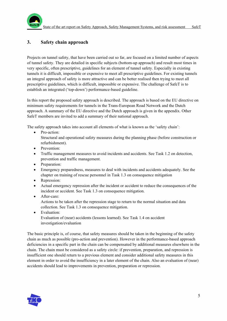
It is important that safety is guaranteed during the entire life cycle of the tunnel. This requires a safety management system. Up till now safety management systems are not available for tunnels and tunnel organisations (at least no references could be found on this subject). Safety management systems are common practise in the chemical process industry. The experience in the chemical process industry can be used for the development of safety management systems in tunnels. Additionally quality management systems such as ISO9004 can be used for guidance [4]. ISO 9004 describes a set of elements by which a quality management system can be developed, implemented and approved. It gives guidelines for the business activities and processes, which should be covered and for the way in which these activities and processes should be worked out in order to achieve defined expectations in an optimal manner. Central to the philosophy of the ISO 9000 series is the Deming management circle (plan → organize → implement → check → plan → ....see figure 1). A quality system then is considered to be the vehicle to support and guarantee the concept of self-regulation; it is defined as the organizational structure, responsibilities, procedures, processes and resources for implementing quality management.
Plan
Organize
Implement
Check
Plan
Organize
Implement
Check
Figure 1 Management circle.
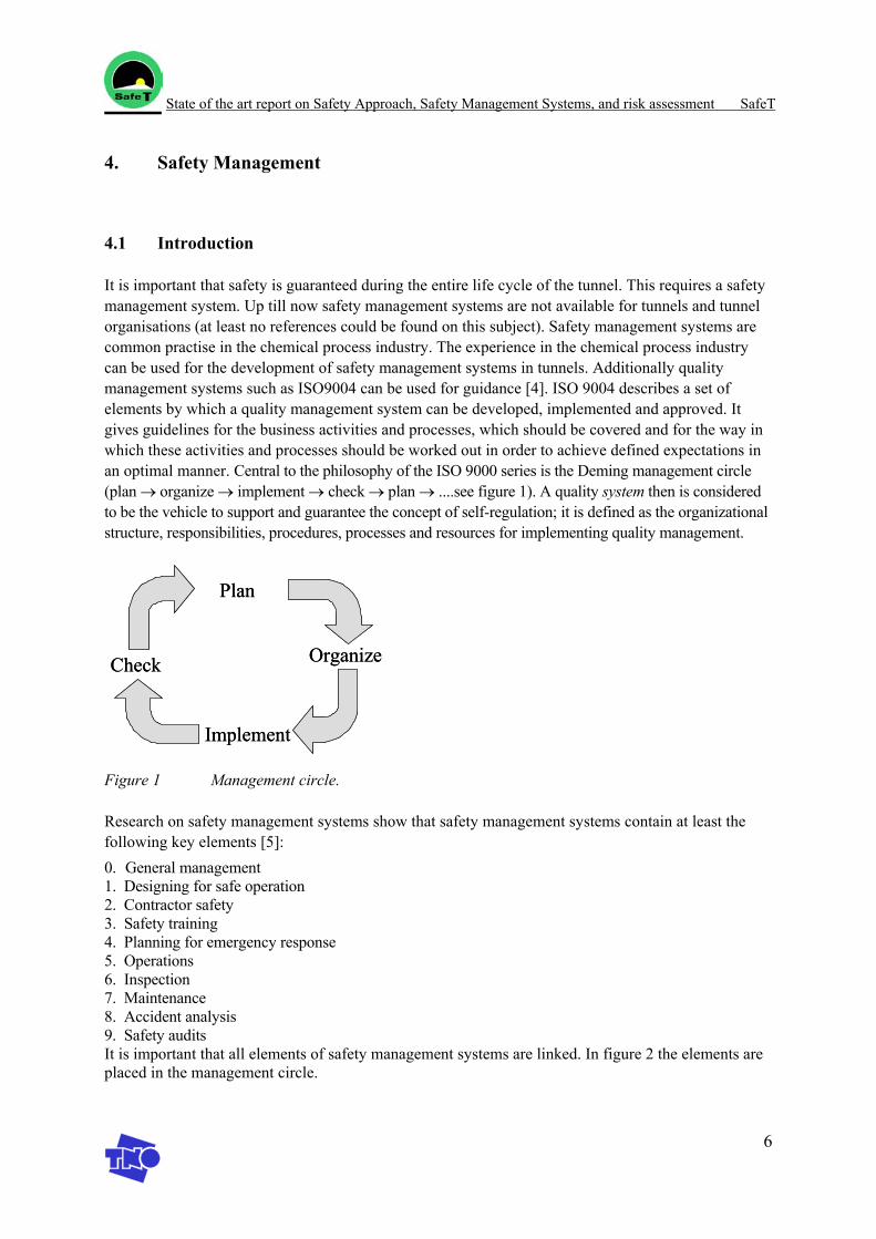
Research on safety management systems show that safety management systems contain at least the following key elements [5]: 0. General management 1. Designing for safe operation 2. Contractor safety 3. Safety training 4. Planning for emergency response 5. Operations 6. Inspection 7. Maintenance 8. Accident analysis 9. Safety audits It is important that all elements of safety management systems are linked. In figure 2 the elements are placed in the management circle.
State of the art report on Safety Approach, Safety Management Systems, and risk assessment SafeT
7
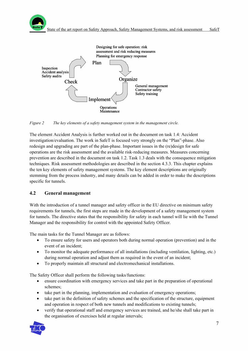
Figure 2 The key elements of a safety management system in the management circle.
The element Accident Analysis is further worked out in the document on task 1.4: Accident investigation/evaluation. The work in SafeT is focused very strongly on the “Plan”-phase. Also redesign and upgrading are part of the plan-phase. Important issues in the (re)design for safe operations are the risk assessment and the available risk-reducing measures. Measures concerning prevention are described in the document on task 1.2. Task 1.3 deals with the consequence mitigation techniques. Risk assessment methodologies are described in the section 4.3.3. This chapter explains the ten key elements of safety management systems. The key element descriptions are originally stemming from the process industry, and many details can be added in order to make the descriptions specific for tunnels.
4.2 General management
With the introduction of a tunnel manager and safety officer in the EU directive on minimum safety requirements for tunnels, the first steps are made in the development of a safety management system for tunnels. The directive states that the responsibility for safety in each tunnel will lie with the Tunnel Manager and the responsibility for control with the appointed Safety Officer.
The main tasks for the Tunnel Manager are as follows: • To ensure safety for users and operators both during normal operation (prevention) and in the
event of an incident; • To monitor the adequate performance of all installations (including ventilation, lighting, etc.)
during normal operation and adjust them as required in the event of an incident; • To properly maintain all structural and electromechanical installations.
The Safety Officer shall perform the following tasks/functions: • ensure coordination with emergency services and take part in the preparation of operational
schemes; • take part in the planning, implementation and evaluation of emergency operations; • take part in the definition of safety schemes and the specification of the structure, equipment
and operation in respect of both new tunnels and modifications to existing tunnels; • verify that operational staff and emergency services are trained, and he/she shall take part in
the organisation of exercises held at regular intervals;
Organize
Plan
Implement
CheckGeneral management
Designing for safe operation: risk assessment and risk reducing measuresPlanning for emergency response
Contractor safetySafety training
OperationsMaintenance
InspectionAccident analysisSafety audits
Organize
Plan
Implement
CheckGeneral management
Designing for safe operation: risk assessment and risk reducing measuresPlanning for emergency response
Contractor safetySafety training
OperationsMaintenance
InspectionAccident analysisSafety audits
State of the art report on Safety Approach, Safety Management Systems, and risk assessment SafeT
8
• give advice on the commissioning of the structure, equipment and operation of tunnels; • verify that the tunnel structure and equipment are maintained and repaired; • take part in the evaluation of any significant incident or accident
The overview of key elements of a safety management system compared with the required tasks of the tunnel manager and the safety officer, show that most key elements are also required tasks for the tunnel manager and the safety officer, although in the EU-directive the emphasis is very much on emergency response. The key elements of a safety management system also include general management, operations and maintenance as being important for the continuity of a safety management system. Inspections, accident analysis and safety audits are tasks of the Inspection Body of the Administrative Body (in the EU directive), but should also be carried out by the tunnel manager itself in order to check and improve its safety organisation.
4.3 Design for safe operation: prescriptive guidelines and risk assessment
4.3.1 Introduction
One of the key elements of a proper safety management system is “design for safe operation”. The safety of a tunnel system is predominantly determined in the design stage. Safety is mostly determined by the quality of this basic design rather than by latter addition of separate safety provisions. A wide variety of aspects must therefore be taken into consideration in the basic design. In order to make an inventory of aspects to be considered and to determine which measures and safety provisions have to be included in the design, use can be made of prescriptive guidelines as well as risk assessment techniques. Both prescriptive guidelines and risk assessment techniques are also applicable for the selection of separate safety provisions for an existing tunnel.
4.3.2 Prescriptive guidelines
With prescriptive guidelines, combined with the use of checklists, it is easy to identify which measures and safety provision have to be taken in a tunnel. Prescriptive guidelines provide a standard set of solutions and have the advantages of setting a consistent benchmark, being relatively easy to apply and resulting in similar designs. With the use of prescriptive guidelines it is made clear in a very early stage which provisions are necessary. A proper estimate of the accompanying costs can be made. It can, however, constrain design freedom and function, leave no room for new, innovative, safety measures, be slow to change and has difficulty in dealing with multiple objectives [11]. In situations were certain safety provisions are difficult to realize, which is especially applicable in case of renovation of an existing tunnel, this might lead to an impasse in the decision making process on the necessary safety provisions. Therefore it is recommended to introduce the principle of equality: a safety provision can be replaced by another set of safety measures when it can be demonstrated (by means of a risk assessment) that this alternative set of measures are equally effective in risk reduction. This principle is adopted in the EU directive and the Dutch and French approach: certain safety measures are prescribed but the use of other safety measures is permitted if the effect of the measures can be shown with a risk assessment.
State of the art report on Safety Approach, Safety Management Systems, and risk assessment SafeT
9
4.3.3 Risk assessment
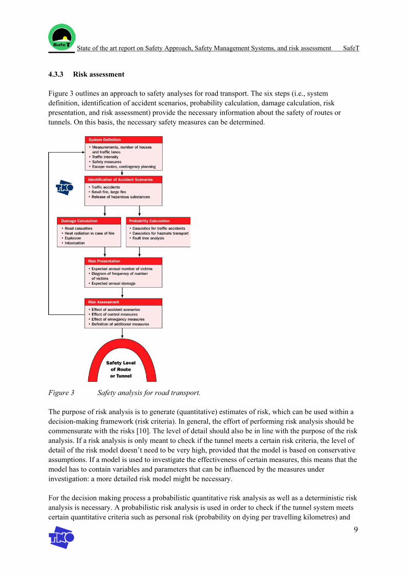
Figure 3 outlines an approach to safety analyses for road transport. The six steps (i.e., system definition, identification of accident scenarios, probability calculation, damage calculation, risk presentation, and risk assessment) provide the necessary information about the safety of routes or tunnels. On this basis, the necessary safety measures can be determined.
Figure 3 Safety analysis for road transport.
The purpose of risk analysis is to generate (quantitative) estimates of risk, which can be used within a decision-making framework (risk criteria). In general, the effort of performing risk analysis should be commensurate with the risks [10]. The level of detail should also be in line with the purpose of the risk analysis. If a risk analysis is only meant to check if the tunnel meets a certain risk criteria, the level of detail of the risk model doesn’t need to be very high, provided that the model is based on conservative assumptions. If a model is used to investigate the effectiveness of certain measures, this means that the model has to contain variables and parameters that can be influenced by the measures under investigation: a more detailed risk model might be necessary.
For the decision making process a probabilistic quantitative risk analysis as well as a deterministic risk analysis is necessary. A probabilistic risk analysis is used in order to check if the tunnel system meets certain quantitative criteria such as personal risk (probability on dying per travelling kilometres) and
State of the art report on Safety Approach, Safety Management Systems, and risk assessment SafeT
10
societal risk (probability on a number of people dying per year). It can also be used to investigate the effectiveness of preventive measures and consequence mitigation techniques.
The effectiveness of consequence mitigation techniques can also be investigated in a deterministic risk analysis. In a deterministic risk analysis a limited number of representative scenarios are elaborated. Deterministic risk analyses provide more information on the development of accidents and are therefore important for the preparation of the emergency response organization.
Both methods are worked out further in section 4.3.3.3 and 4.3.3.4. In both cases a proper identification of the relevant risks is important. Available tools are given in the relevant sections.
4.3.3.1 Bow-tie model
It is important that the risk assessment should incorporate the different stages of an accident (see Table 3-1).
Table 4-1 Stages of an accident.
Process Stage
Nr. Description
1. Initial stage 1 Disruption of the normal course 2. Accident 2 The actual start of the accident 3 The development of the accident 4 Development of unsafe situations for other travellers 3. Detection and warning 5 Detection, warning, verification, reporting information 4. Egress 6 Escape from the tunnel by the travellers on their one strength 5. Emergency response 7 Attendance of the emergency response services 8 Consequence mitigation by the emergency response services
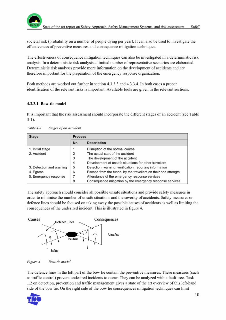
The safety approach should consider all possible unsafe situations and provide safety measures in order to minimise the number of unsafe situations and the severity of accidents. Safety measures or defence lines should be focused on taking away the possible causes of accidents as well as limiting the consequences of the undesired incident. This is illustrated in figure 4.
Figure 4 Bow-tie model.
The defence lines in the left part of the bow tie contain the preventive measures. These measures (such as traffic control) prevent undesired incidents to occur. They can be analyzed with a fault-tree. Task 1.2 on detection, prevention and traffic management gives a state of the art overview of this left-hand side of the bow tie. On the right side of the bow tie consequences mitigation techniques can limit
Causes Consequences
Unsafety
Safety
Defence lines
Incident
Causes Consequences
Unsafety
Safety
Defence lines
Incident
State of the art report on Safety Approach, Safety Management Systems, and risk assessment SafeT
11
damage once an incident has occurred. They can be further analysed with an event-tree. Task 1.3 on consequence mitigation gives a state of the art overview of this right-hand side of the bow tie. In a deterministic risk analysis the focus will be mainly on the left hand side of the bow tie.
4.3.3.2 Hazard identification techniques
In DARTS task 4.1 “identification and quantification of hazards” the following hazards [13]1 are considered: • Fire • Explosion • Collisions (cars, trains) • Earthquakes • Inundation (flooding) • Leakage of aggressive and toxic materials • Dropped anchors2 • Sunken ships3
For each tunnel system the nature and possible magnitude of accidents have to be identified. Several hazard identification techniques are available which can also be used, for the risk assessment of a tunnel system: • Checklist • “What if” analysis • Hazard and operability analysis (HAZOP) • Failure mode, effects and criticality analysis (FMECA) • Fault tree analysis (FTA) • Event tree analysis (ETA) • Cause-consequence analysis • Maximum credible accident analysis (MCA)
Methods such as HAZOP and FMECA have already shown to be very valuable tools for the process industry. Whether their high level of detail is necessary and valuable for risk analysis can be found out in practice.
Checklist A checklist is a tool to evaluate equipment, materials, or procedures. Also, the checklist can be used during any stage of a project to guide the user through common hazards by using standard procedures. A checklist will generally produce compliance with the minimal standards and identify areas that require further evaluation. The result is qualitative, mostly “yes-or-no” decision about compliance with standard procedures.
“What if” analysis
1 N.B. The reference is a draft DARTS Document 2 Only relevant for submerged tunnels 3 Only relevant for submerged tunnels
State of the art report on Safety Approach, Safety Management Systems, and risk assessment SafeT
12
The “What if” procedure concerns the determination of undesired consequences, caused by a deviation in the intended activities. The procedure is not as structured as techniques like HAZOP and FMECA. However, people having skill in using it, regard “What If” Analysis as a strong and easy to use technique. Furthermore, it is thought to be less tedious than other techniques. Subsequently for all parts of the tunnel the study team members ask themselves “What will happen if….”. The team must consist of specialists. The technique results in a qualitative listing of accident scenarios, consequences and possible risk reduction methods.
Hazard and Operability Study A Hazard and Operability Study (HAZOP) is one of the most structured techniques to identify hazards. The method aims to find all deviations from the designed intention of tunnel equipment or functionalities. In brainstorming sessions of a multidisciplinary team, causes and consequences of deviations are identified. A list of so-called “guide words”, defining the deviations, is used to initiate creative thinking about the deviations. If causes and consequences are considered to be realistic and significant, they are recorded on a worksheet-table for follow up action. This action (recommendation) may either be a change in design or equipment, or a follow up study to determine possible consequences, e.g. effect calculations. The method results is a qualitative list of • Identification of hazards and operating problems; • Recommended changes in design and procedures to improve safety; • Recommendations for follow on studies.
Failure mode, effects and criticality analysis Failure mode, effects and criticality analysis (FMECA) is a tabulation of the system/tunnel equipment, their failure modes, each failure mode’s effect on the system and a criticality ranking for each failure mode. The failure mode is a description of how equipment fails (open, closed, on, off, etc.). The effect of the failure mode is the system response or accident resulting from the equipment failure. FMECA identifies single failure modes that either directly result in or contribute significantly to an important accident. Human/ operator errors are generally not examined in a FMECA; however, the effects of misoperation are usually described by an equipment failure mode. FMECA is not efficient for identifying combinations of equipment failures that lead to accidents. The method results in a qualitative reference list of system equipment, with its failure modes and possible hazardous effects. A relative ranking of the severity of equipment failure may be given (criticality).
Fault tree analysis Fault tree analysis (FTA) is a widely used tool for system safety analysis. One of the primary strengths of the method is the systematic, logical development of the many contributing failures that might result in an accident. This type of development requires that the analysts have a complete understanding of the system operation and the various failure modes. FTA breaks down an accident into its contributing equipment failures and human errors. The method therefore is a “reverse-thinking” technique; that is, the analyst begins with an accident or undesirable event that is to be avoided and identifies the immediate causes of that event. Each of the immediate causes is examined in turn until the analyst has identified the basic causes of each event. The fault tree is a diagram that displays the logical interrelationships between these basic causes and the accident.
State of the art report on Safety Approach, Safety Management Systems, and risk assessment SafeT
13
Result is a list of combination sets of failures (both equipment and human failures) that can cause an accident. Although the result is qualitative in itself, it has the potential to use for quantitative evaluation. For that purpose, indications of probabilistic failure rate data are required.
Event tree analysis Event tree analysis evaluates potential accident outcomes that might result following an equipment failure or process upset known as an initiating event. Unlike fault tree analysis, event tree analysis is a “forwardthinking” process; that is the analyst begins with an initiating event and develops the following sequences of events that describe potential accidents, accounting for both the successes and the failures of the safety functions as the accident progresses. Event trees provide a precise way of recording the accident sequences and defining the relationships between the initiating events and the subsequent events that combine to result in an accident. Then by ranking the accidents, or through a subsequent quantitative evaluation, the most important accidents are identified. Event trees are well-suited for analysing initial events that could result in a variety of effects. An event tree emphasises the initial cause and works from the initiating event to the final effects of the event. Each branch of the event tree represents a separate effect (event sequence) that is a clearly-defined set of functional relationships. The qualitative results have a quantitative potential: the success rate of system reactions unto the resulting accident can be calculated if event probabilities are known.
Cause-consequence analysis Cause-consequence analysis combines the “forward-thinking” features of event tree analysis with the “reverse-thinking” features of fault tree analysis. The technique relates specific accident consequences to their many possible basic causes. The result is a cause-consequence diagram that displays the relationships between accident consequences and their basic causes. The solution of the cause-consequence diagram for a particular accident sequence is a list of accident sequence minimal cut sets, representing all the combinations of basic causes that can result in the accident sequence. A quantitative analysis using these sets can provide estimates of the frequency of occurrence of each accident event sequence.
Maximum Credible Accident analysis In Maximum Credible Accident (MCA) analysis, the maximum effects/damages of an accident in the concerned tunnel are calculated. The accidents concern in general the maximum release of hazardous or flammable material (“worst case”) and its resulting heat radiation, explosion blast wave or intoxication. Using physical effect models, like outflow – evaporation – dispersion, the effects of the release unto the surroundings are calculated. The need for further external safety analysis may be determined by these results. The quantitative results are generally conservative.
4.3.3.3 Deterministic risk analysis
A deterministic risk analysis considers how severe a “worst-case” particular scenario might be. It is often used for emergency response teams to see what kinds of situations are possible, that they will have to deal with. A deterministic risk assessment method consists of a number of models, which can be used in coupled or in integrated form. The models are: • Physical effect model
State of the art report on Safety Approach, Safety Management Systems, and risk assessment SafeT
14
The physical effect model describes the physical effects of a fire: temperature, smoke, visibility, influence of ventilation, geometry of the tunnel etc. The physical effect model can be implemented in CFD (computational fluid dynamics) software or zone models. Results of the physical effect model are the fire scenarios.
• Damage models The occupants in the tunnel are exposed to high temperatures, toxic gases and irritant gases. Damage models handle the effect of these circumstances to the occupants and calculate the time available for the occupants to escape to a safe place in- or outside the tunnel.
• Evacuation models Evacuation models are used to calculate the time required for the occupant to escape to a safe place.
A deterministic risk assessment has the advantages of freeing design, facilitating function, addressing new hazards and achieving safety and high tunnel availability [11]. Deterministic risk assessment is especially suitable for preparing rescue teams on what might happen, since an image of the scenario can be created.
Examples of models to perform deterministic risk analysis are: • SIMULEX: a computer program for simulation of egress in road tunnels [14]. • SOLVENT + TunnEVAC [15] • The TNO-trainfire model [19]
Several tools for deterministic risk analysis will be evaluated and compared in Workpackage 5.
4.3.3.4 Probabilistic quantitative risk analysis
Neither prescriptive guidance nor deterministic fire engineering is particularly good at addressing the kind of high consequence/ low frequency fire event that tunnels seem to experience. Quantitative risk assessment, however, considers how severe and how often a wide range of severe events might be. In other words quantitative risk assessment treats the frequency and the consequence sides of the predicted risks with an equal emphasis. It has the advantage that it assesses the level of risk more holistically considering a wide range of event scenarios including the reliability of safety measures and management procedures [11]. Quantitative risk assessment is a useful method to evaluate preventive safety measures on their effect on the total risk. Furthermore it is most suitable to perform cost/benefit analyses of these safety measures.
A probabilistic quantitative risk model can be subdivided into two parts: the probabilities and consequence model. Important techniques to quantify all relevant parameters and probabilities of failure modes are the fault-tree and the event-tree. For the consequence model the same requirements can be written down as for the deterministic model, although in a probabilistic analysis the level of detail in the consequence model might be a bit lower.
State of the art report on Safety Approach, Safety Management Systems, and risk assessment SafeT
15
Some examples of models for probabilistic risk assessment in tunnels are: • TunPrim: a spreadsheet model for Road Tunnel Risk Assessment: a QRA tool for probabilistic
risk assessment [16] • The TNO-trainfire model [19] • SAFIRE (Simple Analytical Fire Risk Evaluation), is a Quantitative fire Risk Assessment
model. It was developed for buildings, the same approach has now been developed for tunnels [11].
• QRAM: Quantitative Risk Assessment Model for risk estimates relevant for transport of dangerous goods through road tunnels. The model is developed for harmonisation of restrictions on transport of dangerous goods during an OECD /PIARC study [17].
• TUSI: a model for estimating the number of incidents, accidents and fires for (Norwegian) Road Tunnels [18].
Several tools for probabilistic risk analysis will be evaluated and compared in Workpackage 5.
4.4 Contractor safety
A substantial part of the maintenance in tunnels is outsourced to contractors. When selecting a contractor, the aim is to employ only those contractors who are able to demonstrate the necessary competence for the work to be done, which includes management of health and safety. Only contractors considered competent should be invited to tender. In order to ensure contractor safety a description of the safety requirements should be made, which the contractor should meet for various activities, such as construction and maintenance. It is necessary to create safety awareness in each of the contractor’s personnel by providing instruction in the employing company’s safety and environmental protection practices and procedures. Before work begins in or near the tunnel, the employing company should identify a qualified person who will monitor the work and safety standards of contractors. Contractors should be required to notify the employing company of all accidents resulting in or having potential for injury or damage. Reports of these accidents would be evaluated by the employing company and discussed with the contractor management.
4.5 Safety training
Safety training is important for as well preventive as repressive purposes. Preventive training aims to obtain a safe operation under normal circumstances. All employees in the organisation should be trained to carry out their work in an effective and safe manner. Job training is determined by the nature of the work carried out and the responsibilities of the position held. Safety training should be given by persons with relevant experience and by safety specialists. The required safety training for each staff member can be specified based on his normal tasks and the risk assessment. The attended training, recommendations and follow up should be filed. Exercises in the tunnel itself are very valuable in safety training, also by the lessons learnt from exercises.
Repressive training aims to improve safety in emergency operation. Rescue personnel and operator training is very important in order to enable the personnel to support the self-rescue process and to adequately intervene in emergency situations. In the task 1.3 SafeT-report several tools for the training of operators and rescue personnel are handled. The tools considered are GAMMA-EC, GATE, and Virtual Fires.
State of the art report on Safety Approach, Safety Management Systems, and risk assessment SafeT
16
In tunnels not only the training of the employees but also the “training” for tunnel users is very important. Information can be supplied with leaflets on how to behave under normal circumstances, or when the normal course is disrupted (e.g. a traffic jam or collision) or in case of an emergency.
4.6 Planning for emergency response
In spite of the many precautions to ensure the safe design, operation and maintenance of the tunnel, from time to time accidents may occur. Collisions, fires or flooding can lead to serious consequences for both man and the environment unless quickly brought under control. Such accidents are possible during maintenance and construction work, as well as during normal operation. The consequences from such accidents more commonly stay within the tunnel, but occasionally may also extend outside the tunnel. Planning must be geared to take account of other people and organisations likely to be involved in the emergency.
The overall objectives of emergency planning are to contain and control emergency accidents, to safeguard people inside and outside the tunnel, and to minimise damage to property and the environment.
These objectives can be obtained aided by: • Detailed emergency procedures; • Performing exercises; • Procedures for updating the information in the emergency procedures; • Follow-up and lessons learnt from the exercises
4.7 Operation
The main safety responsibilities of the tunnel manager are to ensure that: • Established safe operating procedures are used; • Safety rules and standards are obeyed; • Routine safety checks are implemented; • Faulty equipment or procedures are identified and corrected; • Safe conditions for maintenance work are achieved; • All the operators know their roles and actions required in emergency situations.
Safe operating procedures may be defined as those instructions which prevent or minimise the risk of accidents by operation. Safe operating procedures are essential guidance for normal and emergency operation. Strategies for handling during a range of emergency scenario’s are also required. Well-designed procedures need to: • Include clear, precise and logical instructions; • Include actions linked to alarms; • Identify sequenced and conditional actions; • Highlight critical safety steps; An important design of operating procedures is the full involvement and commitment of staff responsible for operation, who are generally encouraged to contribute to improvements based on their experience.
State of the art report on Safety Approach, Safety Management Systems, and risk assessment SafeT
17
Accidents are rare, so the updating of operating procedures in the light of experience is a critical aspect of documentation. Such documentation provides a memory of lessons learnt which might otherwise be lost.
4.8 Inspection
Every effort is made to eliminate failures at source by introducing effective inspection procedures during the construction of the tunnel, and in the selection and quality control of (safety) equipment and other safety measures. Regular inspection of equipment during its lifetime and recording of the results are important for continuing safe use of the tunnel. This needs to be done by experienced professional and technical staff. The objective of these inspections is to confirm both that the equipment and safety features in the tunnel are structurally adequate for continued use, and that components or systems are still functioning according to the design intentions. For the inspections an inspection programme and procedures must be present and it should be recorded how the inspection results are used to improve. Based on a risk identification a description should be made of the activities that should be inspected at interval.
4.9 Maintenance
Management needs to ensure that maintenance strategy reflects the objectives for safety, production and quality assurance. This strategy can be translated into a maintenance plan, which may include the use of contractors to supplement the in-house maintenance workforce. A system will also be available to support the agreed maintenance plan with regard to preventive or predictive maintenance, and to help schedule work and resources to meet operational priorities.
The maintenance function needs qualified professional leadership with trained personnel at all levels.
Clearly defined codes and standards should be used to ensure that the tunnel is maintained correctly, and a records system should be provided to retain details of all inspections and repairs to tunnel and tunnel equipment. It is essential that all maintenance activities maintain (or improve) the integrity of the design.
Clearly defined procedures are needed to ensure that all non-routine activities, such as maintenance work, are carried out safely. For instance a Work Permit system enables proper consideration to be given to the risks prior to work commencing.
4.10 Accident analysis
The Task 1.4 report comprises the results of a literature study to the state of the art on post accident investigation/evaluation. The report is the starting point for Workpackage 4, which will elaborate the subject. This section summarises the Task 1.4 report.
The state of the art report handles the following aspects of accident investigation/evaluation: 1. Types of investigations 2. General accident investigation approach

State of the art report on Safety Approach, Safety Management Systems, and risk assessment SafeT
18
Independent on the size of the accident, the amount of damage caused, or the number of casualties, when an investigation is ordered the investigation should start as soon as possible after the accident, while memories are still fresh and evidence is undisturbed. Depending on the scope, accident investigation may involve assessment of damage, interviewing survivors, interviewing the tunnel-manager and/or -operators and the study of computer simulations. In general the next following steps can be distinguished [2]: 1. remit/scope 2. site visit 3. collection of background information 4. examination of damage 5. interviewing of witnesses and other people involved (tunnel-manager, -operators, etc.) 6. research and analyses 7. reporting
3. Consequences taken from the Mont Blanc and Tauern tunnel disasters The investigation of the Mont Blanc and Tauern tunnel disasters resulted in an assessment of the status quo in all tunnels in Austria longer than 500 meter. This assessment included an inventory of the organisational, construction and electromechanical status of the tunnels. In this section a point-by-point overview per stage of an accident is given of the measures proposed by the Austrian authorities. This gives an overview of lessons learned from these two dramatic accidents.
4. Post accident investigation/evaluation according to the EU directive on minimum safety requirements for tunnels An overview is given of the requirements to post accident investigation/ evaluation in the EU directive [1].
4.11 Safety audits
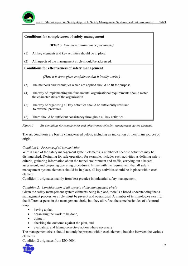
In order to check the completeness and effectiveness of a safety management system (sms) TNO developed an approach to measure the safety performance of an organisation, by checking all nine safety management elements on six conditions. The six conditions for completeness and effectiveness are presented in figure 5 [6].
State of the art report on Safety Approach, Safety Management Systems, and risk assessment SafeT
19
Conditions for completeness of safety management (What is done meets minimum requirements) (1) All key elements and key activities should be in place. (2) All aspects of the management circle should be addressed.
Conditions for effectiveness of safety management (How it is done gives confidence that it 'really works') (3) The methods and techniques which are applied should be fit for purpose. (4) The way of implementing the fundamental organizational requirements should match
the characteristics of the organization. (5) The way of organizing all key activities should be sufficiently resistant to external pressures. (6) There should be sufficient consistency throughout all key activities.
Figure 5 Six conditions for completeness and effectiveness of safety management system elements.
The six conditions are briefly characterized below, including an indication of their main sources of origin.
Condition 1: Presence of all key activities Within each of the safety management system elements, a number of specific activities may be distinguished. Designing for safe operation, for example, includes such activities as defining safety criteria, gathering information about the tunnel environment and traffic, carrying out a hazard assessment, and preparing operating procedures. In line with the requirement that all safety management system elements should be in place, all key activities should be in place within each element. Condition 1 originates mainly from best practice in industrial safety management. Condition 2: Consideration of all aspects of the management circle Given the safety management system elements being in place, there is a broad understanding that a management process, or circle, must be present and operational. A number of terminologies exist for the different aspects in the management circle, but they all reflect the same basic idea of a 'control loop':
• having a plan, • organizing the work to be done, • doing it, • checking the outcome against the plan, and • evaluating, and taking corrective action where necessary.
The management circle should not only be present within each element, but also between the various elements. Condition 2 originates from ISO 9004.
State of the art report on Safety Approach, Safety Management Systems, and risk assessment SafeT
20
Condition 3: Application of methods and techniques which are fit for purpose Methods and techniques which are fit for purpose refer to a suitable level of execution of safety-related activities within elements such as designing, operations and maintenance. Since companies differ from each other and a company with low-risk processes or activities will use other methods and techniques to control safety than a company with a high risk potential, the meaning of the word 'suitable' is specific for a company's business, both with respect to aspects of process safety and with respect to aspects of occupational safety. Condition 3 originates mainly from ISO: it is the technical orientation of the 'fit for purpose' principle in ISO 9004. Systems, methods and techniques should, in a technical sense, be able to cope with risk potentials involved.
Condition 4: Balance between organizational requirements and organizational characteristics Each organization is unique, and differs from other organizations. Its structure, culture, people, norms, values, history and commercial environment are aspects by which this uniqueness may be measured. When implementing policies and plans, insufficient consideration of organizational uniqueness will lead to reduced acceptance or even resistance. Problems with addressing the organizational characteristics reveal themselves through the way in which the fundamental organizational requirements are implemented [7]. In total, eight such requirements are distinguished; examples are (management) commitment to safety, allocation of tasks and responsibilities, coordination and communication, and organizational learning. These eight requirements apply to each organization. Adequate safety management demands that sufficient attention is given to the organizational requirements and that the way of implementing these should match the characteristics of the organization. Condition 4 originates mainly from the SMART framework [7]. It might be called 'organizational fit for purpose', as opposed to the technical fit for purpose which is covered by the previous condition. In a wide sense, it relates to the 'fit for use' principle in ISO 9004.
Condition 5: Resistance to external pressures There are a number of external pressures which can influence the managerial decision making process. Examples of external pressures are commercial and financial constraints, and legal and political constraints. These may affect decisions of management with respect to applicable standards, activities, plans, priorities, working procedures and practices, and follow-up. The willingness of management to accept a lower standard of maintenance in times of serious financial difficulties is a typical example of a consequence of external pressure. Similarly, operating staff may be tempted or pressurized into lowering their margins of safety by 'cutting corners'. These examples show that the decision making process may be influenced in such a way that the eventual decisions cause the introduction of addi-tional risks, consciously or unconsciously. Thus, an effective management of safety requires sufficient resistance to external pressures: they should be addressed in a justifiable way. Condition 5 originates from the SMART framework, in which external pressures are one of the major building blocks.
Condition 6: Consistency Consistency is addressed in a way as applied by Kessels in the development of curricula for training and education purposes [8]. Kessels makes a distinction between external and internal consistency. External consistency refers to the perceptions of those involved in the curricula, such as management, developer and trainee, whereas internal consistency is concerned with the curriculum being consistent in itself. Consistency of safety management can be addressed likewise. At all levels in an organization,
State of the art report on Safety Approach, Safety Management Systems, and risk assessment SafeT
21
employees are exposed to safety management in various ways. Effective safety management demands that these ways display a certain degree of uniformity and consistency. For example, a consistent picture should exist concerning ambitions, plans and priorities, at each level in the organization. Consistency is a condition for policy to be understood. In this sense, consistency may be considered to ensure that all other arrangements throughout a safety management system are in line with each other. Condition 6 does not specifically relate to one of the principal concepts, although ISO 9004 refers to the issue of consistency in general terms. It has primarily been introduced as the 'closing entry' condition which rounds off the series of conditions 1 through 5.
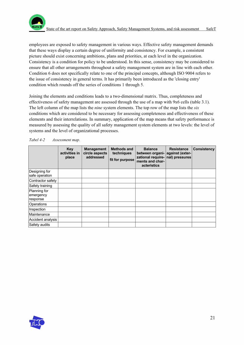
Joining the elements and conditions leads to a two-dimensional matrix. Thus, completeness and effectiveness of safety management are assessed through the use of a map with 9x6 cells (table 3.1). The left column of the map lists the nine system elements. The top row of the map lists the six conditions which are considered to be necessary for assessing completeness and effectiveness of these elements and their interrelations. In summary, application of the map means that safety performance is measured by assessing the quality of all safety management system elements at two levels: the level of systems and the level of organizational processes.
Tabel 4-2 Assessment map.
Key activities in
place
Management circle aspects
addressed
Methods and techniques
fit for purpose
Balance between organi-zational require-ments and char-
acteristics
Resistance against (exter-nal) pressures
Consistency
Designing for safe operation
Contractor safety Safety training Planning for emergency response
Operations Inspection Maintenance Accident analysis Safety audits
State of the art report on Safety Approach, Safety Management Systems, and risk assessment SafeT
22
5. References
[1] Directive 2004/54/EC on minimum safety requirements for tunnels in the Trans-European Road Network, Brussels, 29 April 2004.
[2] Policy document Tunnel Safety, Part A, process requirements, The Netherlands, 2003 (Beleidsnota Tunnelveiligheid, deel A, proceseisen)
[3] Integrated safety philosophy, Centre of Tunnel Safety of the Directorate-General for Public Works and Water Management, the Netherlands, 2002
[4] ISO 9004: Quality management and quality systems- guidelines. International organization for Standardization, 1987
[5] Managing safety. Report no. 4/89, CONCAWE, The Hague, Netherlands, 1989.
[6] On the measurement of safety performance, Jacques F.J. Van Steen and Marten H. Brascamp, TNO-MEP, Apeldoorn, Netherlands, Presented at the 8th International Symposium on Loss Prevention and Safety Promotion in the Process Industries (Antwerp, Belgium, June 1995)
[7] S.A. Brearley and J.F.J. Van Steen, SMART Project on Risk Management: Final report. AEA Technology/TNO, Warrington/Apeldoorn, United Kingdom/Netherlands, 1994.
[8] J.W.M. Kessels, Towards design standards for curriculum consistency in corporate education. PhD Thesis, Twente University of Technology, Enschede, Netherlands, 1993.
[9] Standard for Road tunnel safety, Didier Lacroix, Centre d’Etudes des Tunnels, France, p319-p328
[10] Trbojevic V.M., “Development of risk criteria for a road tunnel”, Fifth International conference on “ Safety in Road and Rail Tunnels”, p. 159-168, 2003.
[11] Charters D., “How can quantitative risk assessment further reduce the risk of tunnel fire accidents?”, Fifth International conference on “ Safety in Road and Rail Tunnels”, p.139-147, 2003.
[12] Robinson R.M., Francis G.E., Anderson K.J., “ Lessons from cause-consequence modelling for tunnel emergency planning”, Fifth International conference on “ Safety in Road and Rail Tunnels”, p.149-158, 2003.
[13] DARTS, “Identification and quantification of Hazards”, Draft document DARTS/4.1, February 2002.
[14] Lynn Lee S.L., Bendelius A., “simulation of escape from road tunnels using SIMULEX”, Fifth International conference on “ Safety in Road and Rail Tunnels”, p.411-420, 2003.
State of the art report on Safety Approach, Safety Management Systems, and risk assessment SafeT
23
[15] Lecointre J., Pons P., “Use of a coupled CFD/evacuation model: application to road tunnels”, Fifth International conference on Safety in Road and Rail Tunnels”, p. 481-489.
[16] Weger D. de, Kruiskamp M.M., Hoeksma J., “Road tunnel risk assessment in the Netherlands - Tunprim: a spreadsheet model for the calculation of the risks in road tunnels”, Safety & Reliability International Conference ESREL 2001.
[17] Kroon I.B., Kampmann J.,“Decision support model for tunnel design and operation”, Fifth International conference on “ Safety in Road and Rail Tunnels”, p.111-120, 2003.
[18] Amundsen F.H., NPRA, “TUSI a model predicting traffic accidents in Norwegian road tunnels”.
[19] DARTS, “Integrated design and redesign”, Chapter 6: casualty modelling in train tunnels, Draft document DARTS Task 5.2, December 2003.
[20] FIT European Thematic Network, “Fire Safe Design, Road Tunnels, Draft 2, Sept. 2003.
State of the art report on Safety Approach, Safety Management Systems, and risk assessment SafeT
24
Appendix: Summary of safety approaches
EU directive on minimum safety requirements for tunnels in the Trans-European Road NetworkThe first objective of the directive is the prevention of critical events that endanger human life, the environment and tunnel installations. The second objective is the reduction of possible consequences (concerning events such as accidents and fires) by providing the ideal prerequisites for:
- enabling people involved in the accident to rescue themselves; - allowing immediate intervention of road users to prevent greater damage; - ensuring efficient action by emergency services; - protecting the environment; - limiting material damage.
In order tot achieve these objectives the directive contains organisational requirements as well as technical requirements. The requirements of the Directive apply to tunnels longer than 500 m in the Trans-European Road Network. It is assumed that tunnel users can escape within 5 to 10 minutes in shorter tunnels. The organisational requirements aim to harmonise the organisation of safety. Every country therefore has to appoint an Administrative Authority seconded by an Inspection Body. Responsibility for safety in each tunnel will lie with the Tunnel Manager and the responsibility for control with the appointed Safety Officer. For each tunnel located on the territory of two Member States, the two administrative authorities or the joint administrative authority shall recognise only one Tunnel Manager and one Safety Officer. The Safety Officer shall perform the following tasks/functions:
(a) ensure coordination with emergency services and take part in the preparation of operational schemes;
(b) take part in the planning, implementation and evaluation of emergency operations; (c) take part in the definition of safety schemes and the specification of the structure,
equipment and operation in respect of both new tunnels and modifications to existing tunnels;
(d) verify that operational staff and emergency services are trained, and he/she shall take part in the organisation of exercises held at regular intervals;
(e) give advice on the commissioning of the structure, equipment and operation of tunnels; (f) verify that the tunnel structure and equipment are maintained and repaired; (g) take part in the evaluation of any significant incident or accident
The administrative authority shall verify that regular inspections are carried out by the inspection entity to ensure that all tunnels falling within the scope of this Directive comply with its provisions. Secondly, the Commission sets technical requirements to reduce the risks of accidents in tunnels relating to infrastructure (ventilation, electromechanical equipment, road signs, panels and pictograms, preference for twin-tube rather than single-tube tunnels), operation of the tunnel by the tunnel manager (maintenance and cooperation with the emergency services), vehicles (carriage of fire extinguishers on heavy goods vehicles, buses and coaches using tunnels, requirement that any additional tanks on heavy goods vehicles passing through tunnels should be empty) and road users (improvement of the level of road safety through information campaigns and better communication between the tunnel manager and road users inside a tunnel). Where certain structural requirements can only be satisfied through technical solutions which either cannot be achieved or can be achieved only at disproportionate cost, the administrative authority may accept the implementation of risk reduction measures as an alternative to application of those requirements, provided that the alternative measures will result in equivalent or improved protection. The efficiency of these measures shall be demonstrated through a risk analysis.
State of the art report on Safety Approach, Safety Management Systems, and risk assessment SafeT
25
Risk analyses, where necessary, shall be carried out by a body which is functionally independent from the Tunnel Manager. The content and the results of the risk analysis shall be included in the safety documentation submitted to the administrative authority. A risk analysis is an analysis of risks for a given tunnel, taking into account all design factors and traffic conditions that affect safety, notably traffic characteristics and type, tunnel length and tunnel geometry, as well as the forecast number of heavy goods vehicles per day. By 30 April 2009 the Commission shall publish a report on the practice followed in the Members States. Where necessary, it shall make proposals for the adoption of a common harmonised risk analysis methodology.
Germany The RABT 2003 is the German Guideline on (road) tunnel safety and it applies to tunnels longer than 80m. In the introductory chapter an overall safety concept is mentioned. The concept is based on a determined typical damaging event (accident, fire, hgv …) and must consist of the following topics:
- loss prevention - notification of loss - self rescue - external rescue - assistance for fire fighting and rescue services
Although the guidelines are nonrigid it is necessary to give reasons in case of differing from the standards of the RABT and it is required to guarantee a high level of safety. In addition to the requirements one has to take into account in the overall safety concept the RABT gives input for the organisation in case of an emergency:
- the emergency management is responsible for the safety of individuals in the tunnel - the institution which is responsible for the operation of the tunnel has to provide
o alarm plans o plans for averting a danger o communication plans with police, fire brigade and rescue services (all plans must be
checked and practised annually) - the institution which is responsible for the operation of the tunnel has to appoint a person in
charge for fire prevention, the person in charge is accountable for: o monitoring the compliance with emergency regulations o reporting on deficiencies (all functions of the person in charge must be recorded)
- the institution which is responsible for the operation of the tunnel has to supply the fire brigade with standardised maps (routes inside building/tunnel relevant for the fire brigade)
The Netherlands
In the Netherlands a new law on tunnel safety is in preparation. At this moment there is no law on tunnel safety, but there are several regulations on tunnel safety. Road tunnels are classified in categories: in category II tunnels no transport of dangerous substances is permitted. In category I tunnels the transport of toxic and flammable fluids is permitted, but transport of flammable gasses is prohibited. Recently discussions took place on allowing the transport of flammable gasses through certain tunnels. In the 1980’s by the Civil Engineering Division of the Directorate-General for Public Works and Water Management developed technical safety requirements for tunnels for internal use in the renovation programme for their tunnels. These safety requirements have evolved in the present technical safety requirements. These technical safety requirements (the basis measures) form one of the five elements of the integral safety approach, which is propagated by the Centre of Tunnel Safety of the Directorate-General for Public Works and Water Management. The integral safety philosophy requires the safety measures and procedures are taken in all links of the safety chain: pro-action, prevention, correction, repression and follow up. This safety approach consists of the following
State of the art report on Safety Approach, Safety Management Systems, and risk assessment SafeT
26
elements: - basic assumptions, preconditions and standards - safety considerations - basic measures - Additional measures and their effectiveness - The safety organisation
This safety philosophy is now incorporated in the proposals for the new tunnel safety law. The proposal applies for all tunnels longer than 250 metres, but also for shorter tunnels with a higher risk (when for instance dangerous substances are transported through the tunnel). In the proposed law the basic measures are not prescribed, but on a large set safety goals is defined. The tunnel owner/builder can choose its own measures in order to meet these safety goals. In addition to the EC directive it is required that each tunnel has to keep up an updated safety file. In this safety file all facts, considerations and choices regarding safety during the complete life time of the tunnel have to be documented. In each phase of the tunnel life (planning, design, construction, use) a clear description about who is primarily responsible has to be given. Requirements for the operation phase will be established in an Operation-permit. The new law introduces an independent expert-group. This expert-group has to be consulted before approving the design, the construction-permit and the operation permit. In the design-phase quantitative and qualitative risk analysis are obliged. In order to provide a systematic guarantee of the safety during the use of the tunnel, for each tunnel a safety management system has to be in operation. In addition to this safety management system an emergency plan has to be available. Finally regular inspections are held (by the inspection body as prescribed in the EU directive and by other authorized bodies such as the municipality
Czech Republic
The Czech guidelines show some similarity to the German RABT guidelines, therefore both guidelines are compared by H/B Verkehrsconsult, (one of the German partners within SafeT) The Czech technical specification of Road Tunnel Equipment is published by the Ministry of Transport of the Czech Republic, Road Department. The Table of Content of the Specifications are pretty much like the Richtlinien für die Ausstattung und den Betrieb von Straßentunneln (RABT). But the content of the text in general is their own. Still there are some parts which are partly “taken over” from the RABT, for ex. the chapter regarding the description of the equipment (3.2.3.1.-3.2.3.3.). Though in Czech Guidelines, they also have the classification for short tunnels, which is not the case in RABT. Criteria for tunnel equipment in terms of road signalling are similar to the German ones. Basic equipment contains some more parameters, such as barriers for the operation closure and information display. Information display provides continually updated information on extraordinary and emergency states in the tunnel. They can be placed before tunnel, at tunnel portal and inside tunnel. Additionally the guidelines include the manner of application of traffic signs in tunnels and adjacent sections (such as warning signs, prohibitory or restrictive signs, mandatory traffic signs, destination traffic signs, …). In the chapter about tunnel lighting there is a figure (Fig. 4-1) similar to one in RABT (Bild 25) but the description is their own. The same can be said for the chapters about safety equipment and communication system. In general, the Czech Guidelines contain more figures than RABT and they can not be said to be “taken over” from the RABT.
France
The France approach is described in two inter-ministerial circulars and LOI no 2002-3 (see summaries below). The French circular does not contain traffic management issues. Furthermore the French risk assessment method
State of the art report on Safety Approach, Safety Management Systems, and risk assessment SafeT
27
is effect-based, it is not a probabilistic approach.
o Inter-ministerial circular n°2000-63 of 25 August 2000 concerning Safety in the Tunnels of National Route Network: the circular relates to the tunnels in the national highways network, including concessionary motorways, whose length is more than 300 metres. As far as its application is concerned tunnels are regarded as being all covered roadways. In the case of these structures the circular establishes a procedure prior to their commissioning and means for monitoring their operation described in Appendix no 1. It therefore amends the previously specified procedures for the investigation and approval of designs. The circular also subjects new tunnels in the national highways network to the rules of technical inspection appended as Appendix n°2.
o Inter-ministerial circular n°2000-82 of 30 November 2000 concerning the regulation of traffic with dangerous goods in road tunnels of the national network: the circular describes and prescribes the application of the results of the joint OECD/PIARC study of transport of dangerous goods for the evaluation of restrictions to road tunnels owned or conceded by the French State.
o Law nr 2002-3 of January 3rd 2002 (J.o. Numéro 3 du 4 Janvier 2002 page 215.) concerning:
- Safety of infrastructures and transport systems - Technical investigation after a maritime-, terrestrial or air transport accident or incident - Safety around underground storage of natural gas, hydrocarbons and chemicals
Article 2 of this law will make it possible to impose similar procedure to the tunnels owned by local communities as to those owned or conceded by the French State.
Approaches in other EU countries
The guidelines of the separate EU countries generally reflect the safety approach of this country. FIT collected, summarised, and compared the guidelines of the following countries:
- France - Switzerland - Germany - Austria - Norway - Sweden - United Kingdom - The Netherlands - USA
For an overview of these guidelines the reader is referred to the FIT document, which is available as a public working document [20].
In Workpackage 7 of SafeT a global tunnel safety approach will be worked out, gathering existing approaches of various countries, tunnels, experts, projects etc. and integrating them in one approach.

SafeT
Work package 1 Task 1.2
D1.2 report
State of the art detection, prevention and traffic management
Version: April 2005 Author: W.W.R. Koch (TNO), C. Ramirez (SICE)
State of the art detection, prevention and traffic management SafeT
2
Table of contents
Table of contents .................................................................................................................................... 2
Abbreviations ......................................................................................................................................... 3
1. Introduction............................................................................................................................. 4
2. Technical measures ................................................................................................................. 6 2.1 Overview of technical measures............................................................................ 11
3. Management of information by tunnel operators.................................................................. 13
4. Incident detection in EU member states ............................................................................... 16
5. Traffic management .............................................................................................................. 17
6. Traffic management in EU member states............................................................................ 19
7. Equipment for detection, prevention and traffic management.............................................. 21 7.1 Introduction ........................................................................................................... 21 7.2 Tunnel systems ...................................................................................................... 22 7.3 Traffic signing ....................................................................................................... 24 7.4 Monitoring systems (CCTV and Automatic Incident Detection Systems)............ 26 7.5 CCTV .................................................................................................................... 26 7.6 Automatic Incident Detection Systems ................................................................. 27 7.7 Emergency phones................................................................................................. 31 7.8 Traffic Management Equipment............................................................................ 31 7.9 Integration aspects, the experience in Spain.......................................................... 32 7.10 Exploitation aspects............................................................................................... 35 7.11 Conclusions ........................................................................................................... 36
8. Discussion ............................................................................................................................. 37
9. References............................................................................................................................. 38
State of the art detection, prevention and traffic management SafeT
3
Abbreviations
CCTV Closed Circuit Television SDS Speed Discrimination System AID Automatic Incident Detection VMS Variable Message Signs RFID Radio Frequency Identification RDS Radio Data System VICS Vehicle Information and Communication System FIT European Thematic network on Fire In Tunnels
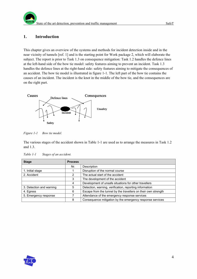
State of the art detection, prevention and traffic management SafeT
4
1. Introduction
This chapter gives an overview of the systems and methods for incident detection inside and in the near vicinity of tunnels [ref. 1] and is the starting point for Work package 2, which will elaborate the subject. The report is prior to Task 1.3 on consequence mitigation: Task 1.2 handles the defence lines at the left-hand side of the bow tie model: safety features aiming to prevent an incident. Task 1.3 handles the defence lines at the right-hand side: safety features aiming to mitigate the consequences of an accident. The bow tie model is illustrated in figure 1-1. The left part of the bow tie contains the causes of an incident. The incident is the knot in the middle of the bow tie, and the consequences are on the right part.
Figure 1-1 Bow tie model.
The various stages of the accident shown in Table 1-1 are used as to arrange the measures in Task 1.2 and 1.3.
Table 1-1 Stages of an accident.
Stage Process Nr. Description 1. Initial stage 1 Disruption of the normal course 2. Accident 2 The actual start of the accident 3 The development of the accident 4 Development of unsafe situations for other travellers 3. Detection and warning 5 Detection, warning, verification, reporting information 4. Egress 6 Escape from the tunnel by the travellers on their own strength 5. Emergency response 7 Attendance of the emergency response services 8 Consequence mitigation by the emergency response services
Causes Consequences
Unsafety
Safety
Defence lines
Incident
Causes Consequences
Unsafety
Safety
Defence lines
Incident

State of the art detection, prevention and traffic management SafeT
5
Aspects of detection, prevention and traffic management that will be regarded in the SafeT project are: 1. Technical measures according to the first three stages in table 1-1 [ref. 1] 2. Management of information by tunnel operators 3. Incident detection in the near vicinity of tunnels [ref. 1] 4. Comparison of the incident detection requirements in the EU directive [ref. 2] and the requirements
in several individual EU member states 5. Traffic Management 6. Comparison of traffic management requirements in the proposal of the EU directive and the
requirements in several individual EU member states. 7. Discussion
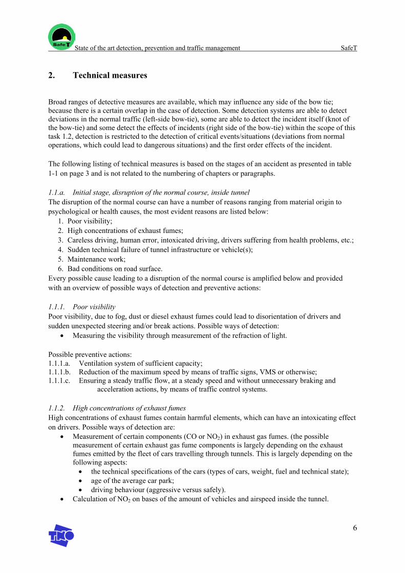
State of the art detection, prevention and traffic management SafeT
6
2. Technical measures
Broad ranges of detective measures are available, which may influence any side of the bow tie; because there is a certain overlap in the case of detection. Some detection systems are able to detect deviations in the normal traffic (left-side bow-tie), some are able to detect the incident itself (knot of the bow-tie) and some detect the effects of incidents (right side of the bow-tie) within the scope of this task 1.2, detection is restricted to the detection of critical events/situations (deviations from normal operations, which could lead to dangerous situations) and the first order effects of the incident.
The following listing of technical measures is based on the stages of an accident as presented in table 1-1 on page 3 and is not related to the numbering of chapters or paragraphs.
1.1.a. Initial stage, disruption of the normal course, inside tunnel The disruption of the normal course can have a number of reasons ranging from material origin to psychological or health causes, the most evident reasons are listed below:
1. Poor visibility; 2. High concentrations of exhaust fumes; 3. Careless driving, human error, intoxicated driving, drivers suffering from health problems, etc.; 4. Sudden technical failure of tunnel infrastructure or vehicle(s); 5. Maintenance work; 6. Bad conditions on road surface.
Every possible cause leading to a disruption of the normal course is amplified below and provided with an overview of possible ways of detection and preventive actions:
1.1.1. Poor visibility Poor visibility, due to fog, dust or diesel exhaust fumes could lead to disorientation of drivers and sudden unexpected steering and/or break actions. Possible ways of detection:
• Measuring the visibility through measurement of the refraction of light.
Possible preventive actions: 1.1.1.a. Ventilation system of sufficient capacity; 1.1.1.b. Reduction of the maximum speed by means of traffic signs, VMS or otherwise; 1.1.1.c. Ensuring a steady traffic flow, at a steady speed and without unnecessary braking and
acceleration actions, by means of traffic control systems.
1.1.2. High concentrations of exhaust fumes High concentrations of exhaust fumes contain harmful elements, which can have an intoxicating effect on drivers. Possible ways of detection are:
• Measurement of certain components (CO or NO2) in exhaust gas fumes. (the possible measurement of certain exhaust gas fume components is largely depending on the exhaust fumes emitted by the fleet of cars travelling through tunnels. This is largely depending on the following aspects: • the technical specifications of the cars (types of cars, weight, fuel and technical state); • age of the average car park; • driving behaviour (aggressive versus safely).
• Calculation of NO2 on bases of the amount of vehicles and airspeed inside the tunnel.
State of the art detection, prevention and traffic management SafeT
7
Possible preventive actions: 1.1.2.a. Ventilation system of sufficient capacity; 1.1.2.b. Reduction of the maximum speed by means of traffic signs, VMS or otherwise; 1.1.2.c. Ensuring a steady traffic flow, at a steady speed and without unnecessary braking and acceleration actions, by means of traffic control systems.
1.1.3. Careless driving, human error, intoxicated driving, drivers suffering from health problems, etc. Careless or intoxicated driving leads to a very unstable driving behaviour which can provoke a chain reaction of unwanted actions from other road users leading to an accident. Possible ways of detection are:
• CCTV-camera’s (closed circuit television) • Inductive detection loops • Radar sensors to measure speed and traffic volume • SDS (speed discrimination system) in combination with a CCTV system (closed circuit
television) • Section control (individual vehicle tracking in a section of a tunnel by means of a video
camera and a laser scanner) (Asfinag, Austria) [ref. 6] • Automatic Speed control for control of speed, headways and weight (if desired) [ref 10].
Disruptions of the normal course, caused by human error and drivers suffering from health problems, are two possible causes which are almost inevitable and impossible to avert. They can only be reduced to a minimum by means of clear communication on what the drivers can expect in and around the tunnel. More general a good sense of the dangers involved with driving through tunnels could be emphasised to the public by the government and tunnels authorities. This can be enhanced by public campaigns endorsing the public to be careful in traffic in general and in tunnels in particular. Another possible preventive action could be a system of certified driving schools paying extra attention to driving through tunnels and the related dangers. Moreover police can pay extra attention to drunk driving in the vicinity of tunnels with severe penalties if caught in the act. In an extreme case certain people might even be prohibited of driving trough tunnels because of their criminal record (speeding, drunk driving, asocial behaviour, etc.).
1.1.4. Sudden technical failure of tunnel infrastructure or vehicle(s). The sudden failure of a tunnel installation (for example: lighting, signalling, ventilation, etc.) or the sudden failure of a car could lead to shock reactions and disorientation of drivers, resulting in sudden unexpected driving behaviour. Possible ways of detecting a broken down vehicle are presented under paragraph 1.2.1. on page 8. The failure of (parts) of the tunnel installation can be detected by:
• CCTV-camera’s (closed circuit television); • Indicators on the control panels of the traffic managers, if applicable; • Use of intercom system or mobile phone (drivers); • Push-button in niche.
Possible preventive actions to prevent a spontaneous break down of tunnel installations or vehicles: 1.1.4.a. Compelled regular maintenance, performed by educated professionals; 1.1.4.b. The use of high quality technical standards and equipment; 1.1.4.c. The installation of a back-up system which automatically comes into action if needed,
ensuring at least a minimum safety level.
State of the art detection, prevention and traffic management SafeT
8
1.1.5. Maintenance work. Regular/planned or unexpected maintenance could lead to unstable driving behaviour which can provoke a chain reaction of unwanted actions from other road users. There is no reason for detecting maintenance work. Possible ways of prevention are: 1.1.5.a. Clear communication on the maintenance works being performed, on a local or nationwide scale depending on the economical impact of the tunnel; 1.1.5.b. Use of VMS or other means of pre-tunnel and in tunnel communication forms to inform the drivers on the work; 1.1.5.c. In an extreme case the tunnel could be (partly) closed down for a period of time in order to prevent incidents/accidents; 1.1.5.d. The use of maintenance free equipment, reducing the amount of service.
1.1.6. Bad conditions on road surface. A slippery, wet or messy road surface could cause vehicles to react differently on braking or accelerating actions of drivers, leading to an unsafe feeling with drivers. This feeling might cause unstable driving behaviour. Possible ways of detection are:
• CCTV-camera’s (closed circuit television); • Multiple temperature and moist detectors placed in the tunnel.
Possible ways of prevention are: 1.1.6.a. Tunnel constructions reducing the volume of incoming rain, fog and litter; 1.1.6.b. The application of sufficient draining capacity; 1.1.6.c. Regular cleaning/sweeping of the tunnel road surface.
1.1.b. Initial stage, disruption of the normal course, outside tunnel
Incident detection in the near vicinity of tunnels Incidents upstream and downstream of tunnels are related to [ref. 1]: 1. The convergence of roadways; 2. Gradients in the road; 3. The change of daylight to artificial light and vice versa;
Possible preventive actions [ref. 1]: A.a. Convergence of roadways should take place well before entering the tunnel;
A.b. Road signs which inform the drivers on what they can expect in the process of entering the tunnel (well informed drivers can focus more on the actual driving);
A.c. Clear information on what they can expect inside the tunnel (e.g. 2 roadways of 2 meters wide, truck lanes, etc.);
A.d. As little convergence as possible; A.e Traffic control systems to harmonise traffic flow.
B.a. Road signs which inform the drivers on what they can expect in the process of entering the tunnel (well informed drivers can focus more on the actual driving);
B.b. In case gradients exceed 3%, additional/reinforced measures should be taken (EU Directive)
B.c Traffic control systems to harmonise traffic flow.
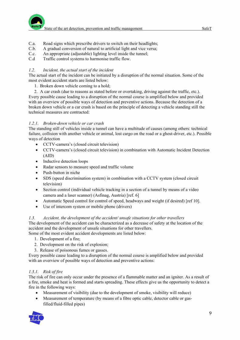
State of the art detection, prevention and traffic management SafeT
9
C.a. Road signs which prescribe drivers to switch on their headlights; C.b. A gradual conversion of natural to artificial light and vice versa; C.c. An appropriate (adjustable) lighting level inside the tunnel; C.d Traffic control systems to harmonise traffic flow.
1.2. Incident, the actual start of the incident The actual start of the incident can be initiated by a disruption of the normal situation. Some of the most evident accident starts are listed below:
1. Broken down vehicle coming to a hold; 2. A car crash (due to reasons as stated before or overtaking, driving against the traffic, etc.).
Every possible cause leading to a disruption of the normal course is amplified below and provided with an overview of possible ways of detection and preventive actions. Because the detection of a broken down vehicle or a car crash is based on the principle of detecting a vehicle standing still the technical measures are contracted:
1.2.1. Broken-down vehicle or car crash The standing still of vehicles inside a tunnel can have a multitude of causes (among others: technical failure, collision with another vehicle or animal, lost cargo on the road or a ghost-driver, etc.). Possible ways of detection
• CCTV-camera’s (closed circuit television) • CCTV-camera’s (closed circuit television) in combination with Automatic Incident Detection
(AID) • Inductive detection loops • Radar sensors to measure speed and traffic volume • Push-button in niche • SDS (speed discrimination system) in combination with a CCTV system (closed circuit
television) • Section control (individual vehicle tracking in a section of a tunnel by means of a video
camera and a laser scanner) (Asfinag, Austria) [ref. 6] • Automatic Speed control for control of speed, headways and weight (if desired) [ref 10]. • Use of intercom system or mobile phone (drivers)
1.3. Accident, the development of the accident/ unsafe situations for other travellers The development of the accident can be characterized as a decrease of safety at the location of the accident and the development of unsafe situations for other travellers. Some of the most evident accident developments are listed below:
1. Development of a fire; 2. Development on the risk of explosion; 3. Release of poisonous fumes or gasses.
Every possible cause leading to a disruption of the normal course is amplified below and provided with an overview of possible ways of detection and preventive actions:
1.3.1. Risk of fire The risk of fire can only occur under the presence of a flammable matter and an igniter. As a result of a fire, smoke and heat is formed and starts spreading. These effects give us the opportunity to detect a fire in the following ways:
• Measurement of visibility (due to the development of smoke, visibility will reduce) • Measurement of temperature (by means of a fibre optic cable, detector cable or gas-
filled/fluid-filled pipes)
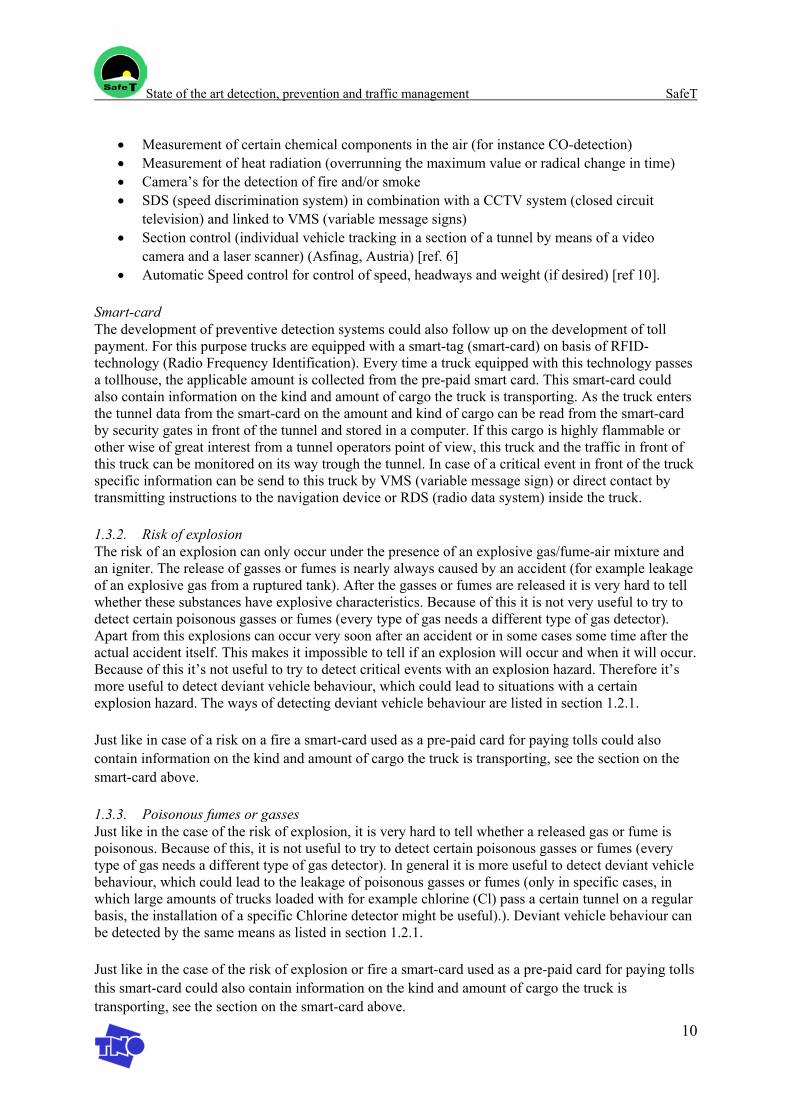
State of the art detection, prevention and traffic management SafeT
10
• Measurement of certain chemical components in the air (for instance CO-detection) • Measurement of heat radiation (overrunning the maximum value or radical change in time) • Camera’s for the detection of fire and/or smoke • SDS (speed discrimination system) in combination with a CCTV system (closed circuit
television) and linked to VMS (variable message signs) • Section control (individual vehicle tracking in a section of a tunnel by means of a video
camera and a laser scanner) (Asfinag, Austria) [ref. 6] • Automatic Speed control for control of speed, headways and weight (if desired) [ref 10].
Smart-card The development of preventive detection systems could also follow up on the development of toll payment. For this purpose trucks are equipped with a smart-tag (smart-card) on basis of RFID-technology (Radio Frequency Identification). Every time a truck equipped with this technology passes a tollhouse, the applicable amount is collected from the pre-paid smart card. This smart-card could also contain information on the kind and amount of cargo the truck is transporting. As the truck enters the tunnel data from the smart-card on the amount and kind of cargo can be read from the smart-card by security gates in front of the tunnel and stored in a computer. If this cargo is highly flammable or other wise of great interest from a tunnel operators point of view, this truck and the traffic in front of this truck can be monitored on its way trough the tunnel. In case of a critical event in front of the truck specific information can be send to this truck by VMS (variable message sign) or direct contact by transmitting instructions to the navigation device or RDS (radio data system) inside the truck.
1.3.2. Risk of explosion The risk of an explosion can only occur under the presence of an explosive gas/fume-air mixture and an igniter. The release of gasses or fumes is nearly always caused by an accident (for example leakage of an explosive gas from a ruptured tank). After the gasses or fumes are released it is very hard to tell whether these substances have explosive characteristics. Because of this it is not very useful to try to detect certain poisonous gasses or fumes (every type of gas needs a different type of gas detector). Apart from this explosions can occur very soon after an accident or in some cases some time after the actual accident itself. This makes it impossible to tell if an explosion will occur and when it will occur. Because of this it’s not useful to try to detect critical events with an explosion hazard. Therefore it’s more useful to detect deviant vehicle behaviour, which could lead to situations with a certain explosion hazard. The ways of detecting deviant vehicle behaviour are listed in section 1.2.1.
Just like in case of a risk on a fire a smart-card used as a pre-paid card for paying tolls could also contain information on the kind and amount of cargo the truck is transporting, see the section on the smart-card above.
1.3.3. Poisonous fumes or gasses Just like in the case of the risk of explosion, it is very hard to tell whether a released gas or fume is poisonous. Because of this, it is not useful to try to detect certain poisonous gasses or fumes (every type of gas needs a different type of gas detector). In general it is more useful to detect deviant vehicle behaviour, which could lead to the leakage of poisonous gasses or fumes (only in specific cases, in which large amounts of trucks loaded with for example chlorine (Cl) pass a certain tunnel on a regular basis, the installation of a specific Chlorine detector might be useful).). Deviant vehicle behaviour can be detected by the same means as listed in section 1.2.1.
Just like in the case of the risk of explosion or fire a smart-card used as a pre-paid card for paying tolls this smart-card could also contain information on the kind and amount of cargo the truck is transporting, see the section on the smart-card above.
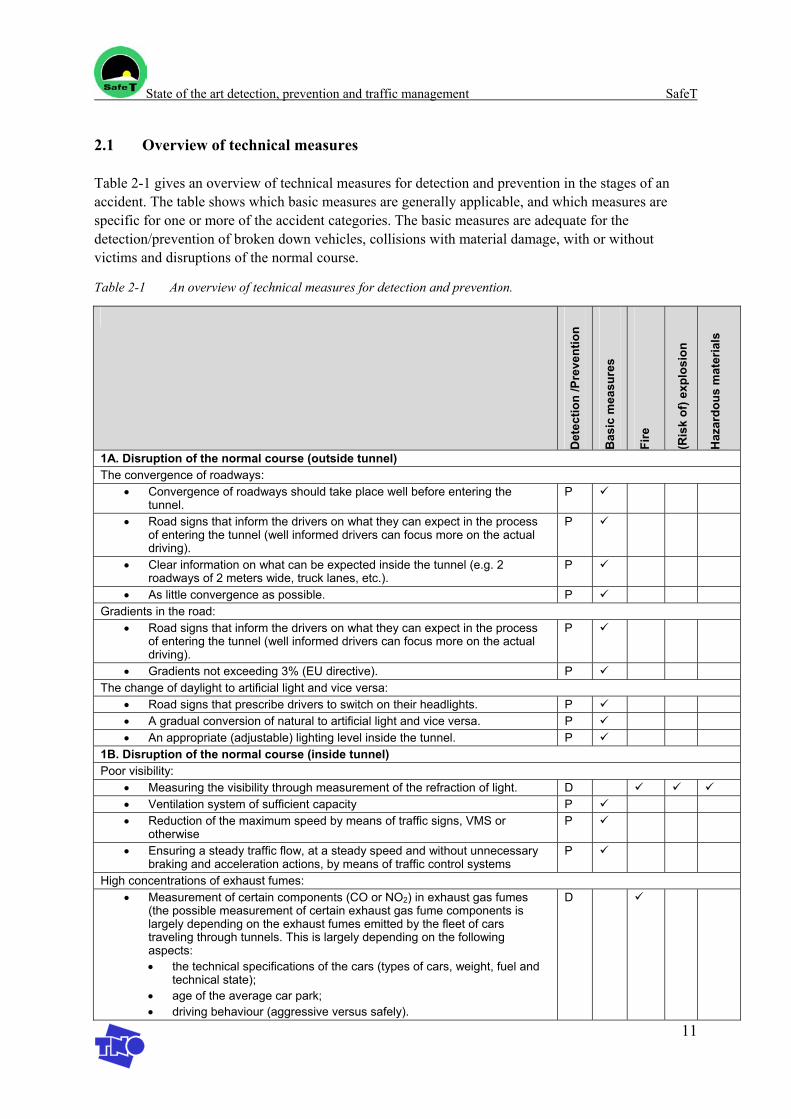
State of the art detection, prevention and traffic management SafeT
11
2.1 Overview of technical measures
Table 2-1 gives an overview of technical measures for detection and prevention in the stages of an accident. The table shows which basic measures are generally applicable, and which measures are specific for one or more of the accident categories. The basic measures are adequate for the detection/prevention of broken down vehicles, collisions with material damage, with or without victims and disruptions of the normal course.
Table 2-1 An overview of technical measures for detection and prevention.
Det
ectio
n /P
reve
ntio
n
Bas
ic m
easu
res
Fire
(Ris
k of
) exp
losi
on
Haz
ardo
us m
ater
ials
1A. Disruption of the normal course (outside tunnel) The convergence of roadways:
• Convergence of roadways should take place well before entering the tunnel.
P
• Road signs that inform the drivers on what they can expect in the process of entering the tunnel (well informed drivers can focus more on the actual driving).
P
• Clear information on what can be expected inside the tunnel (e.g. 2 roadways of 2 meters wide, truck lanes, etc.).
P
• As little convergence as possible. P Gradients in the road:
• Road signs that inform the drivers on what they can expect in the process of entering the tunnel (well informed drivers can focus more on the actual driving).
P
• Gradients not exceeding 3% (EU directive). P The change of daylight to artificial light and vice versa:
• Road signs that prescribe drivers to switch on their headlights. P • A gradual conversion of natural to artificial light and vice versa. P • An appropriate (adjustable) lighting level inside the tunnel. P
1B. Disruption of the normal course (inside tunnel) Poor visibility:
• Measuring the visibility through measurement of the refraction of light. D • Ventilation system of sufficient capacity P • Reduction of the maximum speed by means of traffic signs, VMS or
otherwise P
• Ensuring a steady traffic flow, at a steady speed and without unnecessary braking and acceleration actions, by means of traffic control systems
P
High concentrations of exhaust fumes: • Measurement of certain components (CO or NO2) in exhaust gas fumes
(the possible measurement of certain exhaust gas fume components is largely depending on the exhaust fumes emitted by the fleet of cars traveling through tunnels. This is largely depending on the following aspects: • the technical specifications of the cars (types of cars, weight, fuel and
technical state); • age of the average car park; • driving behaviour (aggressive versus safely).
D
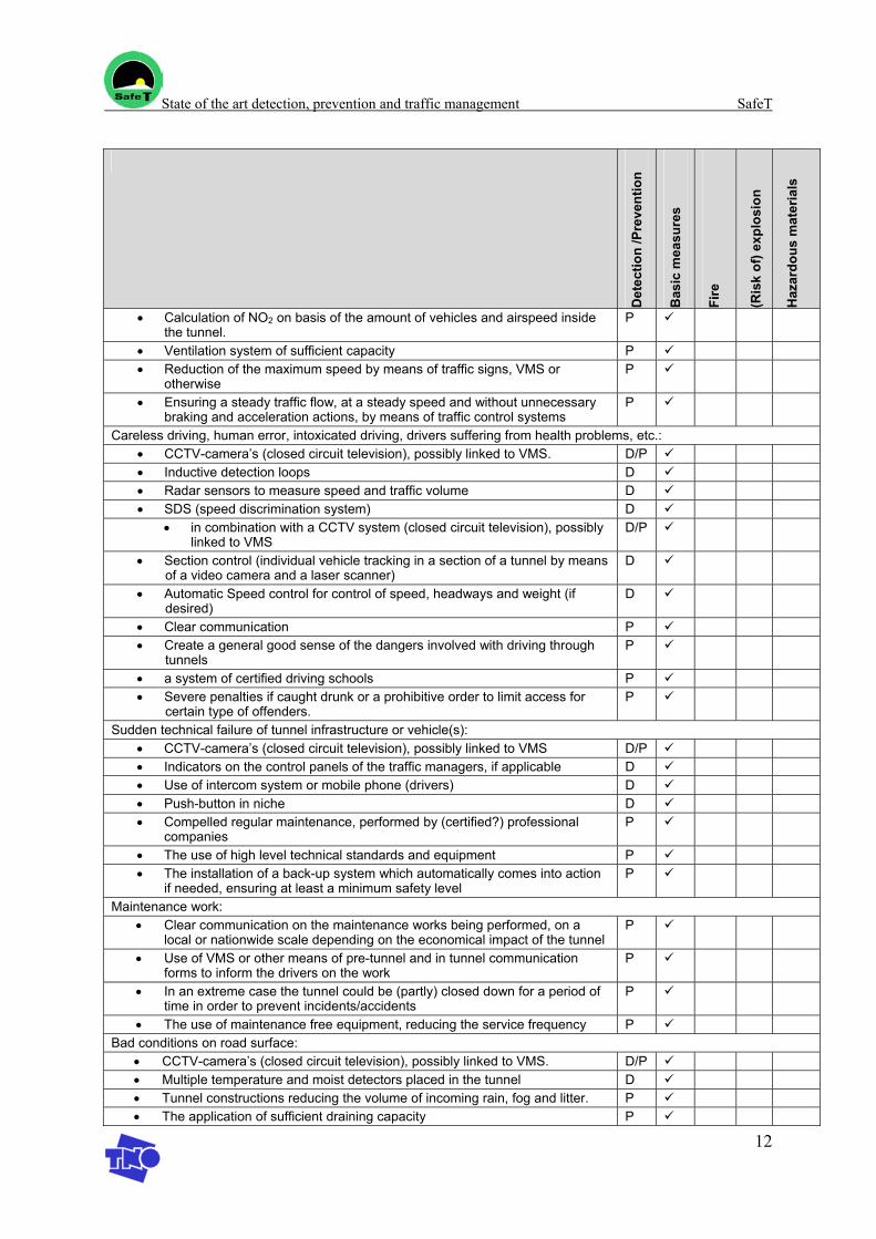
State of the art detection, prevention and traffic management SafeT
12
Det
ectio
n /P
reve
ntio
n
Bas
ic m
easu
res
Fire
(Ris
k of
) exp
losi
on
Haz
ardo
us m
ater
ials
• Calculation of NO2 on basis of the amount of vehicles and airspeed inside the tunnel.
P
• Ventilation system of sufficient capacity P • Reduction of the maximum speed by means of traffic signs, VMS or
otherwise P
• Ensuring a steady traffic flow, at a steady speed and without unnecessary braking and acceleration actions, by means of traffic control systems
P
Careless driving, human error, intoxicated driving, drivers suffering from health problems, etc.: • CCTV-camera’s (closed circuit television), possibly linked to VMS. D/P • Inductive detection loops D • Radar sensors to measure speed and traffic volume D • SDS (speed discrimination system) D
• in combination with a CCTV system (closed circuit television), possibly linked to VMS
D/P
• Section control (individual vehicle tracking in a section of a tunnel by means of a video camera and a laser scanner)
D
• Automatic Speed control for control of speed, headways and weight (if desired)
D
• Clear communication P • Create a general good sense of the dangers involved with driving through
tunnels P
• a system of certified driving schools P • Severe penalties if caught drunk or a prohibitive order to limit access for
certain type of offenders. P
Sudden technical failure of tunnel infrastructure or vehicle(s): • CCTV-camera’s (closed circuit television), possibly linked to VMS D/P • Indicators on the control panels of the traffic managers, if applicable D • Use of intercom system or mobile phone (drivers) D • Push-button in niche D • Compelled regular maintenance, performed by (certified?) professional
companies P
• The use of high level technical standards and equipment P • The installation of a back-up system which automatically comes into action
if needed, ensuring at least a minimum safety level P
Maintenance work: • Clear communication on the maintenance works being performed, on a
local or nationwide scale depending on the economical impact of the tunnel P
• Use of VMS or other means of pre-tunnel and in tunnel communication forms to inform the drivers on the work
P
• In an extreme case the tunnel could be (partly) closed down for a period of time in order to prevent incidents/accidents
P
• The use of maintenance free equipment, reducing the service frequency P Bad conditions on road surface:
• CCTV-camera’s (closed circuit television), possibly linked to VMS. D/P • Multiple temperature and moist detectors placed in the tunnel D • Tunnel constructions reducing the volume of incoming rain, fog and litter. P • The application of sufficient draining capacity P
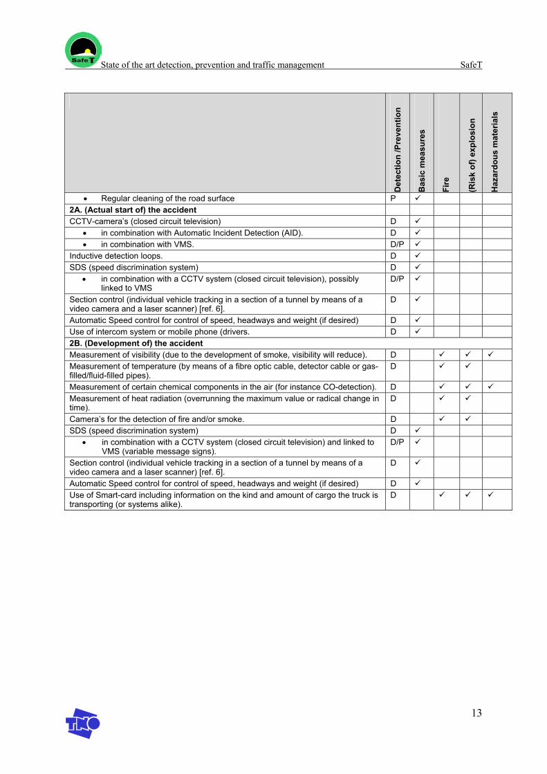
State of the art detection, prevention and traffic management SafeT
13
Det
ectio
n /P
reve
ntio
n
Bas
ic m
easu
res
Fire
(Ris
k of
) exp
losi
on
Haz
ardo
us m
ater
ials
• Regular cleaning of the road surface P 2A. (Actual start of) the accident CCTV-camera’s (closed circuit television) D
• in combination with Automatic Incident Detection (AID). D • in combination with VMS. D/P
Inductive detection loops. D SDS (speed discrimination system) D
• in combination with a CCTV system (closed circuit television), possibly linked to VMS
D/P
Section control (individual vehicle tracking in a section of a tunnel by means of a video camera and a laser scanner) [ref. 6].
D
Automatic Speed control for control of speed, headways and weight (if desired) D Use of intercom system or mobile phone (drivers. D 2B. (Development of) the accident Measurement of visibility (due to the development of smoke, visibility will reduce). D Measurement of temperature (by means of a fibre optic cable, detector cable or gas-filled/fluid-filled pipes).
D
Measurement of certain chemical components in the air (for instance CO-detection). D Measurement of heat radiation (overrunning the maximum value or radical change in time).
D
Camera’s for the detection of fire and/or smoke. D SDS (speed discrimination system) D
• in combination with a CCTV system (closed circuit television) and linked to VMS (variable message signs).
D/P
Section control (individual vehicle tracking in a section of a tunnel by means of a video camera and a laser scanner) [ref. 6].
D
Automatic Speed control for control of speed, headways and weight (if desired) D Use of Smart-card including information on the kind and amount of cargo the truck is transporting (or systems alike).
D
State of the art detection, prevention and traffic management SafeT
14
3. Management of information by tunnel operators
All the information generated by the different detection systems can only serve their purpose if they are interpretated by trained tunnel operators and communicated to the other vehicles inside the tunnels. Thus proper training and means of communication are vital to prevent further incidents from happening or minimize the effects of the incident. Below per stage and process number the possible preventive actions are described.
1.1. Initial stage, disruption of the normal course
1.1.1. Poor visibility Poor visibility could be improved by linked controllable ventilation, which switches on or to a higher number of revolutions in case a certain threshold value is crossed or a time average threshold is being crossed. This could also be done in combination with Variable Message Signs (VMS), prescribing the maximum speed and the minimum distance in between vehicles. Other preventive actions in this case are the prescribed use of headlights and a controllable level of lighting inside the tunnel.
1.1.2. High concentrations of exhaust fumes High concentrations of exhaust fumes could be reduced by linked controllable ventilation, which switches on or to a higher number of revolutions in case a certain threshold value is crossed or a time average threshold is being crossed. This could also be done in combination with Variable Message Signs (VMS), prescribing the maximum speed and thus reducing the emissions of NO2 and CO. In an extreme case the decision can be taken to (partly) close the tunnel down.
1.2. Accident: 1 The actual start of the accident
1.2.1. Broken-down vehicle or accident Information on halted vehicles could be communicated to the drivers by Variable Message Signs (VMS)/lane signalling, informing the other drivers what has happened and/or prescribing the actions to be taken (maximum speed, minimum distance in between vehicles, instructing the partial use of lanes, etc.). Furthermore in near future it might be possible to send a warning message with instructions on how to act could be transmitted to the navigation devices inside the vehicles. (VICS navigation system in Japan [ref. 7]). Besides this a warning message could be transmitted on the standard radio frequencies or by means of RDS. (Obliging people to turn on their radio to a certain frequency, on entering a tunnel).
1.3. Accident, the development of the accident/ unsafe situations for other travellers
1.3.1. Risk of fire The judgement of the tunnel operators can be communicated to the drivers by Variable Message Signs (VMS), informing the other drivers what has happened, prescribing the actions to be taken (maximum speed, minimum distance in between vehicles, stop, etc.). Another preventive option is to prohibit or restrict the transport of flammable cargo (for example prohibit the transport of these goods during daytime).
State of the art detection, prevention and traffic management SafeT
15
1.3.2. Risk of explosion Because it is impossible to tell if an explosion will occur after an accident it’s only useful to detect deviant vehicle behaviour, which could lead to situations with a certain explosion hazard. Another more definite preventive option is to simply prohibit or restrict the transport of certain hazardous goods ((high) explosive or flammable chemicals), for example restrict or prohibit the transport of these goods during daytime.
1.3.3. Poisonous fumes or gasses Because it is impossible to tell if fumes or gasses being released after an accident it’s only useful to detect deviant vehicle behaviour, which could lead to situations in which poisonous fumes or gasses could be released in case of an accident. Another more definite preventive option is to simply prohibit or restrict the transport of certain hazardous goods (explosive, toxic, flammable or poisonous chemicals), for example restrict or prohibit the transport of these goods during daytime.
3.1.1.1 Conclusion
As can be concluded from the above, the prevention of critical events is the number-one priority, which means that the most important measures to be taken have to be of a preventive nature. Therefore it is especially important for tunnel operators to be able to detect deviant vehicle behaviour and take the right actions to restore normal vehicle behaviour. They can only do this when they can compare the situations with a standard or reference situation how vehicles normally pass “their” tunnel. Proper training and regular training (in cooperation with rescue personnel) is of the utmost importance. See the second part of this chapter on traffic management for further details on measures to maintain normal vehicle behaviour.
State of the art detection, prevention and traffic management SafeT
16
4. Incident detection in EU member states
According to the EU directive on minimum safety requirements for tunnels in the Trans-European Road Network the primary objective for reaching the optimal level of safety in road tunnels is the prevention of critical events that may endanger human life, the environment and tunnel installations. The second objective is the reduction of possible consequences (concerning events such as accidents and fires) by providing the ideal prerequisites. The prevention of critical events is therefore the number-one priority, which means that the most important measures to be taken have to be of a preventive nature. The requirements of the Directive only apply to tunnels longer than 500 meter in the Trans-European Road Network. Beside these general requirements more specific demands on incident detection are included under “Monitoring systems” in the EU directive.
Below a short description is given of the automatic incident detection requirements in the individual EU member states participating in FIT. This overview is based on the information given on the FIT internet site: (European Thematic Network on Fire in Tunnels, paragraph E54 Automatic incident detection of the Public Working Document – Draft 2 of September 2003) is given:
• France; Circ2000-63A2 3.9 “automatic incident detection may be provided” • UK; BD78/99 9.52 “The need for CCTV Alert shall be discussed.” • Norway; no reference • Germany: RABT
o Fires: automatic fire detection systems are mandatory in tunnels longer than 400m and in tunnel with mechanical ventilation respectively. The system must detect a fire of 5 Mwatt within 1 Minute (air speeds ≤ 6m/s) and locate the fire with an accuracy of 50m. As a general rule the fire detection should be a linear temperature detector backed by measurement of visibility. It is possible to use thermal or video cameras if they meet the above mentioned requirements.
o Traffic Incidents: for road tunnels longer than 400m with more than 15.000 vehicles/day/lane are required: traffic data detection every 300m in the tube and traffic data detection after the end of the tunnel. The traffic data detection after the end of the tunnel is to detect congestion which could lead to dangerous situations. There are no specific recommendations how to process with the data which is collected every 300m.
• Czech Republic: Czech guidelines provide information about automatic incident detection systems.
In comparison with the requirements of some of the individual EU member states participating in FIT (an European Thematic Network on Fire in Tunnels) it is striking that none of the participating partners have clear regulations on this issue, other FIT participants have no requirements or only some minor information. Note: the fact that there is no clear regulation on this subject does not mean these issues are not addressed in the individual EU member states participating in FIT and does not say anything on the safety of individual tunnels or tunnels in general in these countries.
State of the art detection, prevention and traffic management SafeT
17
5. Traffic management
Traffic management is aimed at traffic monitoring and control. The technical installations, which can be used for traffic detection, have been described before. Just to be clear, these measures are listed below:
• Visual observation • CCTV-camera’s (closed circuit television) • Inductive detection loops • SDS (speed discrimination system) in combination with a CCTV system • Section control (individual vehicle tracking in a section of a tunnel by means of a video
camera and a laser scanner) (Asfinag, Austria) • Automatic Speed control for control of speed, headways and weight (if desired)
All these systems generate important information on if and how traffic is moving in tunnels. The generation of this kind of information is only useful if it is being interpretated by well-trained tunnel operators in a traffic management centre. They also should have the means of communicating their expert judgement to the drivers.
Most important for the tunnel operators in the traffic management centre is the fact that they are well-trained and they should be able to base their judgement on a reference situation. This means they should know what kind and how vehicles normally pass “their” tunnel. This reference situation, from a traffic management point of view, can be created by:
• Traffic signs, prescribing the following: • a prescribed distance between vehicles, for trucks and coaches in particular; • a prescribed maximum speed; • prescribed use of headlights; • separate truck lanes; • a ban on overtaking;
• Height detection; • An appropriate road geometry, alignment and surface; • An appropriate lighting level inside the tunnel; • Universal construction of tunnels and road markings inside tunnels; • Clear road markings; • Regulations prohibiting the transportation of (certain) explosive or flammable chemicals in (a)
(certain) tunnel(s); • Two-way traffic inside one tunnel should be prevented (unidirectional traffic); • Information (brochure, internet, etc.) for professional drivers (truck and coach drivers)
possibly supplement with compulsory fire-extinguish equipment in the vehicles of professional users;
• Specific training for professional drivers transporting certain hazardous goods ((high) explosive, flammable poisonous chemicals);
• Despite the minimum of maintenance needed inside a tunnel (minimum maintenance design) proper/correct maintenance is needed;
• Specific attention to driving through tunnels and how to act in case of a tunnel incident by driving schools;
• A prescribed (periodic) motor vehicle test, reducing the change of a technical failure of vehicles.
State of the art detection, prevention and traffic management SafeT
18
In case of an emergency, appropriate actions can be taken and communicated to the drivers in the tunnel by means of:
• Traffic lights (forcing drivers to avoid a certain traffic lane in case of a broken down vehicle); • Variable message signs (informing on the nature of the incident and what to do); • Barriers for closing down the tunnel or blocking of certain traffic lanes; • Use of an intercom system (in case traffic has (partly) already stopped); • A warning message with instructions on how to act could be transmitted to the navigation
devices inside the vehicles [ref. 7]; • In case of an incident inside the tunnel a warning message could be transmitted on the
standard radio frequencies or by means of RDS. This implies the obligation for drivers to turn on their radio and tune in on a certain frequency, on entering a tunnel;
• In case of an accident inside the tunnel a warning message could be transmitted to mobile phones of drivers inside a tunnel (This implies the obligation for drivers to turn on their mobile phone, on entering a tunnel);
• Smart-card for trucks, see the section on the smart-card in paragraph 1.3.1 on page 7.
It is clear that the type and implementation of traffic installations is depending on the length of the tunnel and traffic intensity.
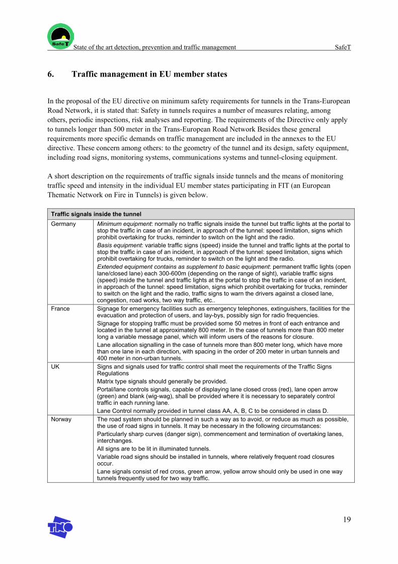
State of the art detection, prevention and traffic management SafeT
19
6. Traffic management in EU member states
In the proposal of the EU directive on minimum safety requirements for tunnels in the Trans-European Road Network, it is stated that: Safety in tunnels requires a number of measures relating, among others, periodic inspections, risk analyses and reporting. The requirements of the Directive only apply to tunnels longer than 500 meter in the Trans-European Road Network Besides these general requirements more specific demands on traffic management are included in the annexes to the EU directive. These concern among others: to the geometry of the tunnel and its design, safety equipment, including road signs, monitoring systems, communications systems and tunnel-closing equipment.
A short description on the requirements of traffic signals inside tunnels and the means of monitoring traffic speed and intensity in the individual EU member states participating in FIT (an European Thematic Network on Fire in Tunnels) is given below.
Traffic signals inside the tunnel Germany Minimum equipment: normally no traffic signals inside the tunnel but traffic lights at the portal to
stop the traffic in case of an incident, in approach of the tunnel: speed limitation, signs which prohibit overtaking for trucks, reminder to switch on the light and the radio. Basis equipment: variable traffic signs (speed) inside the tunnel and traffic lights at the portal to stop the traffic in case of an incident, in approach of the tunnel: speed limitation, signs which prohibit overtaking for trucks, reminder to switch on the light and the radio. Extended equipment contains as supplement to basic equipment: permanent traffic lights (open lane/closed lane) each 300-600m (depending on the range of sight), variable traffic signs (speed) inside the tunnel and traffic lights at the portal to stop the traffic in case of an incident, in approach of the tunnel: speed limitation, signs which prohibit overtaking for trucks, reminder to switch on the light and the radio, traffic signs to warn the drivers against a closed lane, congestion, road works, two way traffic, etc..
France Signage for emergency facilities such as emergency telephones, extinguishers, facilities for the evacuation and protection of users, and lay-bys, possibly sign for radio frequencies. Signage for stopping traffic must be provided some 50 metres in front of each entrance and located in the tunnel at approximately 800 meter. In the case of tunnels more than 800 meter long a variable message panel, which will inform users of the reasons for closure. Lane allocation signalling in the case of tunnels more than 800 meter long, which have more than one lane in each direction, with spacing in the order of 200 meter in urban tunnels and 400 meter in non-urban tunnels.
UK Signs and signals used for traffic control shall meet the requirements of the Traffic Signs Regulations Matrix type signals should generally be provided. Portal/lane controls signals, capable of displaying lane closed cross (red), lane open arrow (green) and blank (wig-wag), shall be provided where it is necessary to separately control traffic in each running lane. Lane Control normally provided in tunnel class AA, A, B, C to be considered in class D.
Norway The road system should be planned in such a way as to avoid, or reduce as much as possible, the use of road signs in tunnels. It may be necessary in the following circumstances: Particularly sharp curves (danger sign), commencement and termination of overtaking lanes, interchanges. All signs are to be lit in illuminated tunnels. Variable road signs should be installed in tunnels, where relatively frequent road closures occur. Lane signals consist of red cross, green arrow, yellow arrow should only be used in one way tunnels frequently used for two way traffic.
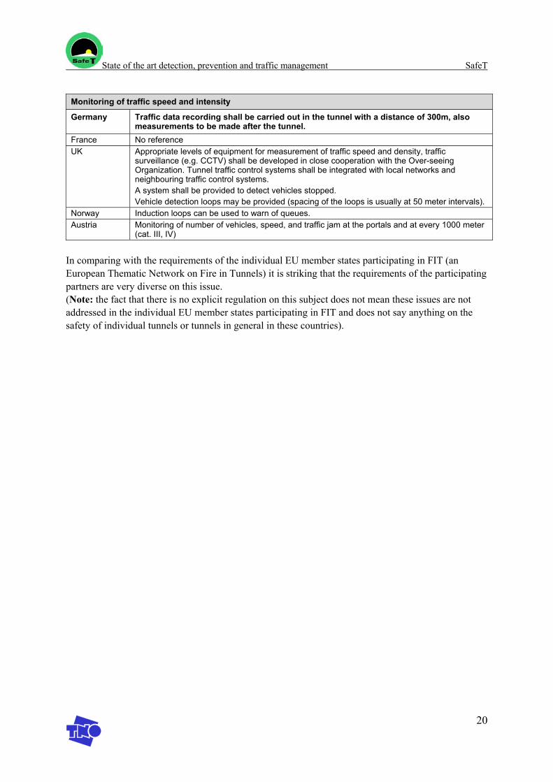
State of the art detection, prevention and traffic management SafeT
20
Monitoring of traffic speed and intensity
Germany Traffic data recording shall be carried out in the tunnel with a distance of 300m, also measurements to be made after the tunnel.
France No reference UK Appropriate levels of equipment for measurement of traffic speed and density, traffic
surveillance (e.g. CCTV) shall be developed in close cooperation with the Over-seeing Organization. Tunnel traffic control systems shall be integrated with local networks and neighbouring traffic control systems. A system shall be provided to detect vehicles stopped. Vehicle detection loops may be provided (spacing of the loops is usually at 50 meter intervals).
Norway Induction loops can be used to warn of queues. Austria Monitoring of number of vehicles, speed, and traffic jam at the portals and at every 1000 meter
(cat. III, IV)
In comparing with the requirements of the individual EU member states participating in FIT (an European Thematic Network on Fire in Tunnels) it is striking that the requirements of the participating partners are very diverse on this issue. (Note: the fact that there is no explicit regulation on this subject does not mean these issues are not addressed in the individual EU member states participating in FIT and does not say anything on the safety of individual tunnels or tunnels in general in these countries).
State of the art detection, prevention and traffic management SafeT
21
7. Equipment for detection, prevention and traffic management
Author: C. Ramirez (SICE)
7.1 Introduction
This section represents SICE’s contribution to task 1.2 which deals with the current approach, guidelines, legislation and current practice in tunnel safety particularly focusing on incident and accident detection and prevention.
This document mostly focuses on the equipment that is recommended, required by law and/or currently used in relation to the detection and prevention of incidents including traffic regulation outside and inside the road tunnels.
The description given here has been compiled from a number of sources including company’s expertise, other EU projects, namely FIT, and existing legislation and recommendations. When necessary, reference to the bibliography is provided within the text.
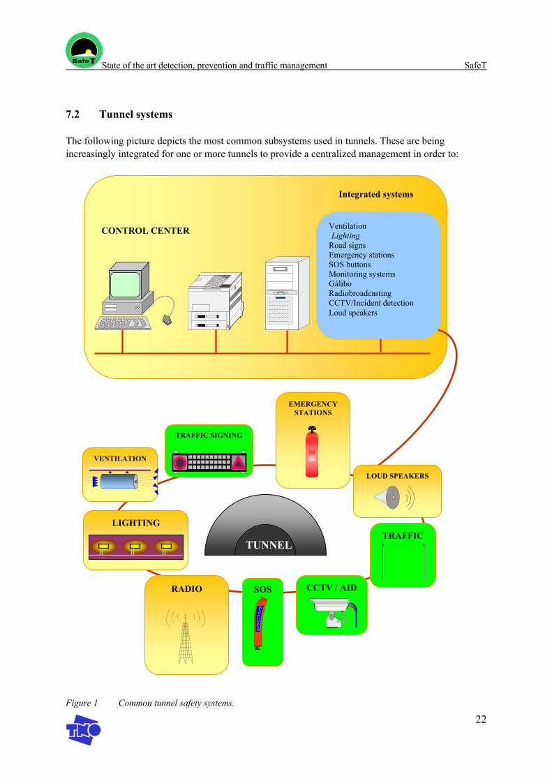
State of the art detection, prevention and traffic management SafeT
22
7.2 Tunnel systems
The following picture depicts the most common subsystems used in tunnels. These are being increasingly integrated for one or more tunnels to provide a centralized management in order to: Figure 1 Common tunnel safety systems.
Ventilation Lighting
Road signs Emergency stations SOS buttons Monitoring systems Gálibo Radiobroadcasting CCTV/Incident detection Loud speakers
CONTROL CENTER
Integrated systems
VENTILATION
LIGHTING
RADIO
TRAFFIC SIGNING
SOS
EMERGENCY STATIONS
CCTV / AID
LOUD SPEAKERS
TRAFFIC TUNNEL
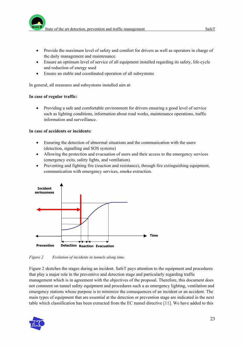
State of the art detection, prevention and traffic management SafeT
23
• Provide the maximum level of safety and comfort for drivers as well as operators in charge of
the daily management and maintenance. • Ensure an optimum level of service of all equipment installed regarding its safety, life-cycle
and reduction of energy used • Ensure an stable and coordinated operation of all subsystems
In general, all measures and subsystems installed aim at:
In case of regular traffic:
• Providing a safe and comfortable environment for drivers ensuring a good level of service such as lighting conditions, information about road works, maintenance operations, traffic information and surveillance.
In case of accidents or incidents:
• Ensuring the detection of abnormal situations and the communication with the users (detection, signalling and SOS systems)
• Allowing the protection and evacuation of users and their access to the emergency services (emergency exits, safety lights, and ventilation).
• Preventing and fighting fire (reaction and resistance), through fire extinguishing equipment, communication with emergency services, smoke extraction.
Prevention Detection Reaction Evacuation
Incident seriousness
Time
Figure 2 Evolution of incidents in tunnels along time.
Figure 2 sketches the stages during an incident. SafeT pays attention to the equipment and procedures that play a major role in the preventive and detection stage and particularly regarding traffic management which is in agreement with the objectives of the proposal. Therefore, this document does not comment on tunnel safety equipment and procedures such a as emergency lighting, ventilation and emergency stations whose purpose is to minimize the consequences of an incident or an accident. The main types of equipment that are essential at the detection or prevention stage are indicated in the next table which classification has been extracted from the EC tunnel directive [11]. We have added to this
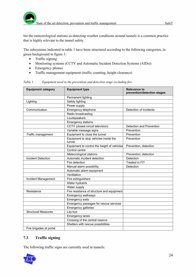
State of the art detection, prevention and traffic management SafeT
24
list the meteorological stations as detecting weather conditions around tunnels is a common practice that is highly relevant to the tunnel safety.
The subsystems indicated in table 1 have been structured according to the following categories, in green background in figure 1:
• Traffic signing • Monitoring systems (CCTV and Automatic Incident Detection Systems (AIDs)) • Emergency phones • Traffic management equipment (traffic counting, height clearance)
Table 1 Equipment used in the prevention and detection stage excluding fire
Equipment category Equipment type Relevance to prevention/detection stages
Permanent lighting Lighting Safety lighting Power supply Communication Emergency telephone Detection of incidents Radio broadcasting Loudspeakers Emergency stations CCTV (closed circuit television) Detection and Prevention Variable message signs Prevention Traffic management Equipment to close the tunnel Prevention Equipment to stop vehicles inside the
tunnel Prevention
Equipment to control the height of vehicles Prevention, detection Control centre Meteorological stations Prevention, detection Incident Detection Automatic incident detection Detection Fire detection Treated in FIT Manual alarm possibility Detection Automatic alarm equipment Ventilation Incident Management Fire extinguishers Water hydrants Water supply Resistance Fire resistance of structure and equipment Emergency walkways Emergency exits Emergency passages for rescue services Emergency galleries Structural Measures Lay-bys Emergency lanes Crossing of the central reserve Shelters with rescue possibilities Fire brigades at portal
7.3 Traffic signing
The following traffic signs are currently used in tunnels:
State of the art detection, prevention and traffic management SafeT
25
Outside the tunnel: • Speed limit • Height clearance • Traffic lights • Lights on/off • Overtake restriction • Other restrictions (cyclist, pedestrians) • Information signs (radio station, tunnel name, length) • Lane control (open green arrow, closed red cross) • Variable Message Signs (VMS)
Inside the tunnel: • Safety signing (safety exits, escape routes, safety recesses and lay-bys) • Road Markings (cat-eyes, edge lines) • Lane control (open green arrow, closed red cross) • Speed limit • Traffic lights • Variable Message Signs
A comparative analysis of the requirements that apply to the use of the above signs in Germany; France, UK, Norway, the Netherlands and Austria is presented in the FIT report [8]. The tunnel directive [11] provides also a proposal that regulates the use of road signing.
While details can be obtained from the above bibliographical references, generally speaking, the following fixed road signs outside the tunnel represent the minimum information that is to be provided for all tunnels: speed limit, height clearance, traffic lights, lights on/off, overtake restriction, other restrictions and information signs. This must be in agreement with national traffic sign regulation requirements.
Inside the tunnel, it is recommended to keep fixed road signing to the minimum. Only safety signing clearly marking safety exits, escape routes, safety recesses and lay-bys are proposed in the tunnel directive [11], as well as road markings (cat-eyes and edge lines). When tunnels are long, speed limit reminders have to be also installed inside the tunnel.
Depending on tunnel classification (subject to length, traffic flow and surveillance), both [8] and [11] contain recommendations and/or obligations concerning the implementation of lane control equipment, Variable Message Signs and Traffic lights inside and outside the tunnel
In summary, tunnel information is made available to road users through both fixed road signs and electronic equipment such as lane control equipment, traffic lights and variable message signs which information can be updated depending on the traffic conditions and events.
Variable Message Signs are particularly flexible in terms of the information that it is able to supply. VMS offers numerous possibilities for the prevention of incidents and/or accidents through the provision of messages that may include:
• General information (Road works, pavement status, meteorological conditions)
State of the art detection, prevention and traffic management SafeT
26
• Road information from monitoring systems (accidents, congestion, lane use, lane change, recommended speed, use of carriageways)
• Road information from other systems (alternative itineraries, congestion status of alternative itineraries)
Regulations concerning the information that has to be supplied to the driver through Variable Message Signing, lane control equipment and traffic lights focus at present on operations concerning tunnel closure and accident management [11]. Non harmonized recommendations about the use of messages for preventive safety exist nowadays.
Current practices, beyond the requirements of the tunnel directive, include particularly the use of VMS within the possibilities outlined in the previous paragraphs. This allows drivers to obtain early information about the tunnel traffic conditions and to adapt consequently their driving.
7.4 Monitoring systems (CCTV and Automatic Incident Detection Systems)
Closed Circuit Television (CCTV) and Automatic Incident Detection (AID) are both mandatory systems for class I and II tunnels in the tunnel directive [11] while they are recommendable or optional for the rest. National regulations in Germany; France, UK, Norway, the Netherlands and Austria do not contain specific references for AIDs but CCTV is regulated depending on tunnel features, see FIT report [8]
AIDs represent a recent evolution of CCTV systems, which extends the surveillance capability of the latest to the automatic detection of incidents. In the following, the use of these systems is described.
7.5 CCTV
Close circuit television systems enable the operators of the control centre to visually verify any accident or incident that has taken place or that is received by telephone notification or through alarms produced by other control systems. At the same time, the CCTV system allows to register the different situations so that a later analysis can be made.
The possibilities that a system of these characteristics offers are varied and of vital importance:
• Traffic monitoring: the vision of the traffic in the accesses and inside the tunnel serves as support to the operators to verify the real traffic conditions, either by direct observation, or like means of verification of possible erroneous information from other systems (fire alarm, automatic detection of incidents...).
• Monitoring of meteorological conditions: the vision of the surrounding tunnel access areas serves as support for the operators to verify the climatologic conditions of the zone and their possible influence in the security of the drivers.
• Support the operators during specific operations: In this sense, the direct vision is the only possible form of verification of a certain circumstance (correct operation of a part of the system, validation of phases in a determined protocol of performance as closing of tracks, etc.).
State of the art detection, prevention and traffic management SafeT
27
• Support in the management of incidents: The CCTV systems constitute one of the key elements in the control and monitoring of the different phases after an incident happens such as: detection, verification, information, answer, work in field and cleaning.
CCTV systems are composed of:
• Field equipment for image taking which includes cameras and the relevant structural components that host the power supply, the control and the communication equipment. Inside the tunnels, cameras are usually mounted on the side walls. Outside the tunnel they are mounted 10 to 15m above the ground on top of metallic columns.
• Communication networks to transfer images between the field equipment and the control centre. Commonly fibre optics is used as it provides sufficient bandwidth for real time video transmission and higher resistance to electromagnetic interferences
• Control centre equipment for the visualization and management of images. The basic architecture of the control centre is based on the following elements:
o Commutation video matrix for the commutation of the video signals coming from
different cameras o Visualization equipment: monitors, video walls etc. o Recording equipment, analogical or digital. o PC application (hardware and/or software). o Export of images towards other applications: other control centres, web server, etc.
The main operations managed at the control centre are:
o Visualization of the images according to a pre-established sequence or as demanded by the operator that controls the camera motion and zoom.
o Visualization of a determined camera under alarm, i.e. the reception of an alarm (for example, an AID), immediately activates the monitoring of the nearest camera.
o Recording of images according to a pre-established sequence, as demanded by the operator or triggered off by an alarm.
7.6 Automatic Incident Detection Systems
Video Automatic Incident Detection (AID) is a technology for automatic real time detection of traffic incidents on roadways based on image processing techniques.
It uses images from CCTV video cameras. Those images are processed in an analyser by means of an algorithm that extracts pertinent information about incident alarms and traffic measurements. This information is then transmitted to a supervisor and it is used for the management of the traffic.
AID systems provide an alarm quickly after the event occurs, even before the consequences of the incident can be noticed by an operator or a traditional surveillance system. It enables users to be warned in good time and reduces the risk of multiple accidents.
The image is the key element, a universal and consensual language. Images remove all doubt, allow for detailed analysis, and are easily transmitted.
State of the art detection, prevention and traffic management SafeT
28
System functioning
AID systems extract information on objects inside the monitored scene from a succession of video image treated by image processing techniques through appropriate algorithms.
The presence of vehicles is detected in each image by comparison between the actual image and a “background” image permanently updated by the system. Vehicles are identified by means of morphological filters that enable to associate a marker to each vehicle.
The algorithm tracks the marker (vehicle) through the sequence of images (tracking) and analyses its movement to build up the time-space trajectory. New filters enable to eliminate non significant trajectories corresponding generally to artefacts.
The vehicle tracking system produces individual vehicle measurements such as presence, speed or stationary vehicles. A later isometric analysis enables to produce also true traffic measurements.
Comparing those measurements with preset thresholds allows detecting incidents and producing an alarm. Aggregating those individual measurements enables to characterize the traffic flow.
To avoid false alarms, the algorithm performs elaborated checking such as: • Identification of non-vehicle objects (vehicle tracking) • Differentiation of shadows and vehicles (object superposition techniques) • Identification of permanent shadows or obstacles (dynamic background image)
Detection capabilities
The following type of alarms can be produced, treated and made available to the supervisor by an AID system:
Incident detection alarms
• Vehicles stopped under normal traffic conditions • Vehicles stopped under congested traffic conditions • Vehicles stopped on the emergency lane, access ramp,… • Beginning and end of traffic slow-down for a group of vehicles • Traffic congestion • Slow vehicles on the emergency lane • Slow vehicles under normal traffic conditions • Pedestrian on the emergency lane • Wrong way vehicle on the emergency lane • Wrong way vehicle under normal traffic conditions
Each of those incidents generates an alarm that can be transmitted to the AID Server. The system is able to grade priorities in order to avoid multiple alarms pointing to the same incident.
Traffic alarms
State of the art detection, prevention and traffic management SafeT
29
• Queue length exceeding a threshold • Vehicle speed exceeding a threshold • Headway exceeding a threshold
All thresholds are set at system installation and can be dynamically adjusted according to traffic conditions.
Self-diagnosis alarms of the AID system
The system runs self-diagnostics on the equipment and automatically detects the following faults:
• Camera shifted from its reference position • Signal loss from the camera • Poor quality video signal from the camera • Analyser failure • Network communication problem
Traffic measurements
The AID system can also provide real-time traffic measurements for each lane of traffic: • Flow rate • Speed • Occupancy rate • Headway • Queue length
System performance
Commercially available AID systems have detection rates (ability to detect incidents) that vary between 95 to 99,9% depending on the type of alarm generated. This is measured as the number of incidents detected over the total number of incidents that take actually place. The response time depends on the type of incident detected and it varies between 2 to 10 seconds.
False alarms occur when the system sends an alarm that does not match any of the incidents the systems is able to detect. The frequency rate is about 2,5 % per day.
Experience shows that the above performance depends largely on a number of parameters and the appropriate configuration and implementation of equipment at the deployment site. This includes:
• Area covered by the cameras • Camera characteristics: focal lens,… • Position of the cameras: layout, height, support stability, position with respect to traffic lanes
(centre, side,…) • Obstacles such as trees, VMS,… • Lightning system • Traffic conditions (for traffic measurements only)
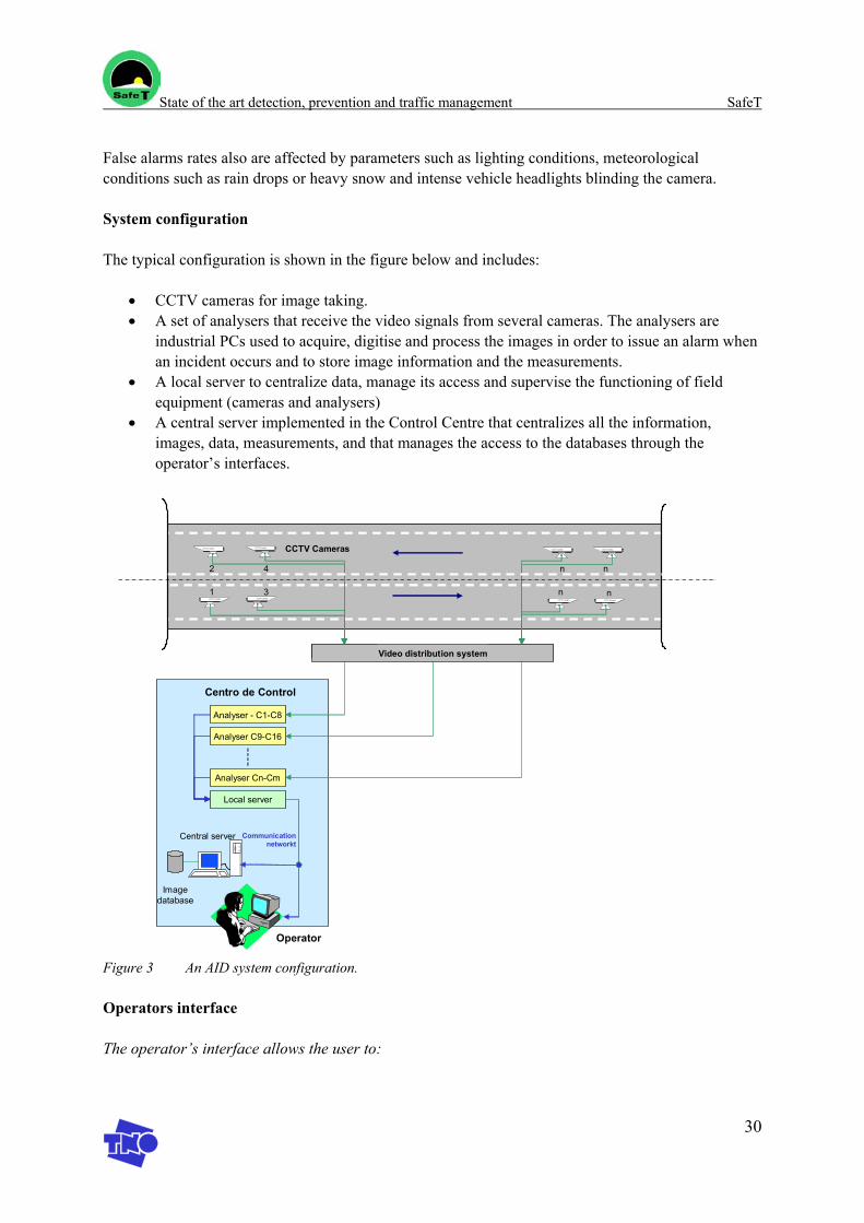
State of the art detection, prevention and traffic management SafeT
30
False alarms rates also are affected by parameters such as lighting conditions, meteorological conditions such as rain drops or heavy snow and intense vehicle headlights blinding the camera.
System configuration
The typical configuration is shown in the figure below and includes:
• CCTV cameras for image taking. • A set of analysers that receive the video signals from several cameras. The analysers are
industrial PCs used to acquire, digitise and process the images in order to issue an alarm when an incident occurs and to store image information and the measurements.
• A local server to centralize data, manage its access and supervise the functioning of field equipment (cameras and analysers)
• A central server implemented in the Control Centre that centralizes all the information, images, data, measurements, and that manages the access to the databases through the operator’s interfaces.
n1 3 nCCTV CameraCCTV Camera
CCTV CameraCCTV C amera
CCTV Cameras
n
CCTV Camera
n
CCTV Camera
2 4
CCTV C ameraCCTV C amera
Centro de Control
Central server Communication networkt
Analyser - C1-C8
Analyser C9-C16
Analyser Cn-Cm
Operator
Local server
Image database
Video distribution system
Figure 3 An AID system configuration.
Operators interface
The operator’s interface allows the user to:
State of the art detection, prevention and traffic management SafeT
31
• Monitor the images, the traffic parameters and the different categories of alarms issued by the system (self diagnosis, road incidents, traffic measurements)
• To set up the system and traffic parameters and to adjust the detection thresholds to the tunnel layout and the different areas under control (lay-by, emergency lanes, ramps)
• To visualize video sequences for the database or form a incident just occurred in order to assess the situation.
• To monitor the system (communications, cameras, processes, even and log files) for maintenance purposes.
7.7 Emergency phones
Emergency phones are used for the manual communication of incidents by drivers and as a communication mean to instruct the driver who has called about how to proceed in a given situation.
They are also used in specific modes for communication with service crews during maintenance operations.
Emergency phones are switched on normally through an alarm push button (SOS) that connects the user with the relevant organization (control centre, police traffic).
The installation requirements summarized in [8] and vary in the different countries. Generally, emergency phones are available for nearly all tunnels but the distance and detailed arrangements vary. The following parameters are included in different national guidelines.
• Distance between emergency phones is established according to tunnel classification and varies from 50 to 500m
• Emplacement that can be together with emergency stations, in lay bys or as stand alone units. • Protection from the traffic area is sometimes contemplated in the regulations [8] and/or
recommended. • Appropriate signs and lighting has to be provided to indicate where the emergency phones are
located.
Emergency phones are contemplated by the EC directive [11] every 250 m inside emergency stations and also at lay-bys.
7.8 Traffic Management Equipment
Traffic management is an essential aspect of preventive safety to avoid incidents and to prevent those, when they happen, from becoming a more serious one or an accident.
Besides the monitoring systems previously commented, CCTV and AIDs which are also dedicated to traffic monitoring and management, the following type of equipment is also used:
• Traffic lights • Variable Message Signs (VMS) • Lane control equipment • Barriers (Equipment to close the tunnel)
State of the art detection, prevention and traffic management SafeT
32
• Traffic counting. • Height clearance detectors. • Meteorological stations
Traffic lights, Variable Message Signs and Lane Control equipment were already treated within the road signing equipment section.
Access barriers have become necessary to reinforce tunnel closure procedures, as only operators well know that drivers often disregard traffic lights even in case of an emergency or incident happening.
The EC directive [11] does not include recommendations about traffic counting equipment and no general synthesis can be concluded from the FIT report [1].
Traffic data recordings are usually performed by making use of detection loops to register speed, traffic density and vehicle type. It is common practice to install them in such a way that traffic measurements can be monitored to predict traffic levels and congestion. This allows the operators to update the traffic information that is distributed through VMS and in agreement with the traffic situation.
Indication of height or height restrictions are part of the minimum requirements to be accomplished by the vertical road signing in some national regulations (see [8]), but it is not surprisingly included in the EC directive [11]. Height clearance equipment is neither compulsory but it is often used to control trucks before the tunnel’s access. The system may be mechanical (i.e. based on the physical contact between the truck and small pieces of metal pending from a gateway) or electronic. In the latest, the detection combines the use of infrared sensors to detect vehicle height and induction loops to confirm vehicle type. When a vehicle is above the height limit, the equipment issues and alarm to the control centre and an electronic panel ahead displays a warning message to the driver.
Meteorological stations which are not mentioned in either the FIT report [8] or the EC directive proposal [11] are essential equipment that may not only affect the tunnel ventilation conditions but also the road traffic. These stations are used to monitor the weather conditions around the tunnel in order to inform users about road surface hazards and conditions alike that affect road safety.
The management for the transport for dangerous goods does not require specific equipment, besides road signing depicting the limitations that apply for a particular tunnel. The recommendations made by the EC report [11] apply rather to the operations and the method to be followed to decide upon the management of transport of dangerous goods.
7.9 Integration aspects, the experience in Spain
Currently, as discussed in Espinosa, [12], we must bear in mind that modern tunnels, given the technological advances, have increasingly more complex systems that require their exploitation and operating to be dealt with effectively, requiring increasingly more qualified staff for operations, exploitation and maintenance.
State of the art detection, prevention and traffic management SafeT
33
All of the systems operating in a tunnel may operate independently, although this situation is not currently justified, it being much more interesting to deal with them globally, i.e. overall management of the complete system.
Integration is a technological aspect that strongly affects tunnel safety as it is the way to put into practice an integrated safety approach where the information provided by a subsystem may be used to optimise the operations of the rest. The saving in power and the greater response speed in the event of an emergency are clear examples of the suitability of dealing with the system as a whole.
This section revises several integration aspects and the current situation and technological trends in Spain.
At present, new tunnels are fitted with those systems established by national and international recommendations as a whole. However, up to now there are no criteria in Spain to homogenize the equipment, systems and control software and to make it compatible amongst manufacturers.
Homogenisation and standardization of ITS equipment looks at providing:
• Mid and long-term independence for the manufacturer and installer • Facilitate initial engineering work and equipment integration. • Enabling the application of general and particular exploitation rules of the tunnel derived from
the recommendations (i.e. automatic execution of processes when an emergency occurs) • Documentation, training and maintenance. • Provision of a homogenous database for suitable distribution to consultants.
The current approach pursuits to obtain a Unique Management System under a single Software Application, where all subsystems implemented are interrelated.
The basic requirements of a control system to be installed in a tunnel for centralized integrated management are:
• It must be reliable. • It must be easy to use. • It must be open and scalable. In other words, it must easily allow for the incorporation of new
applications or subsystems to increase its features.
As in any other more or less complex control structure, there are basically three levels:
• Field Equipment, • Communications • Control centre
The integration of all these levels and the different operating modes (manual, assisted or automatic) must be established in the system which involves considering the design of equipment and software through OPEN SYSTEM architecture.
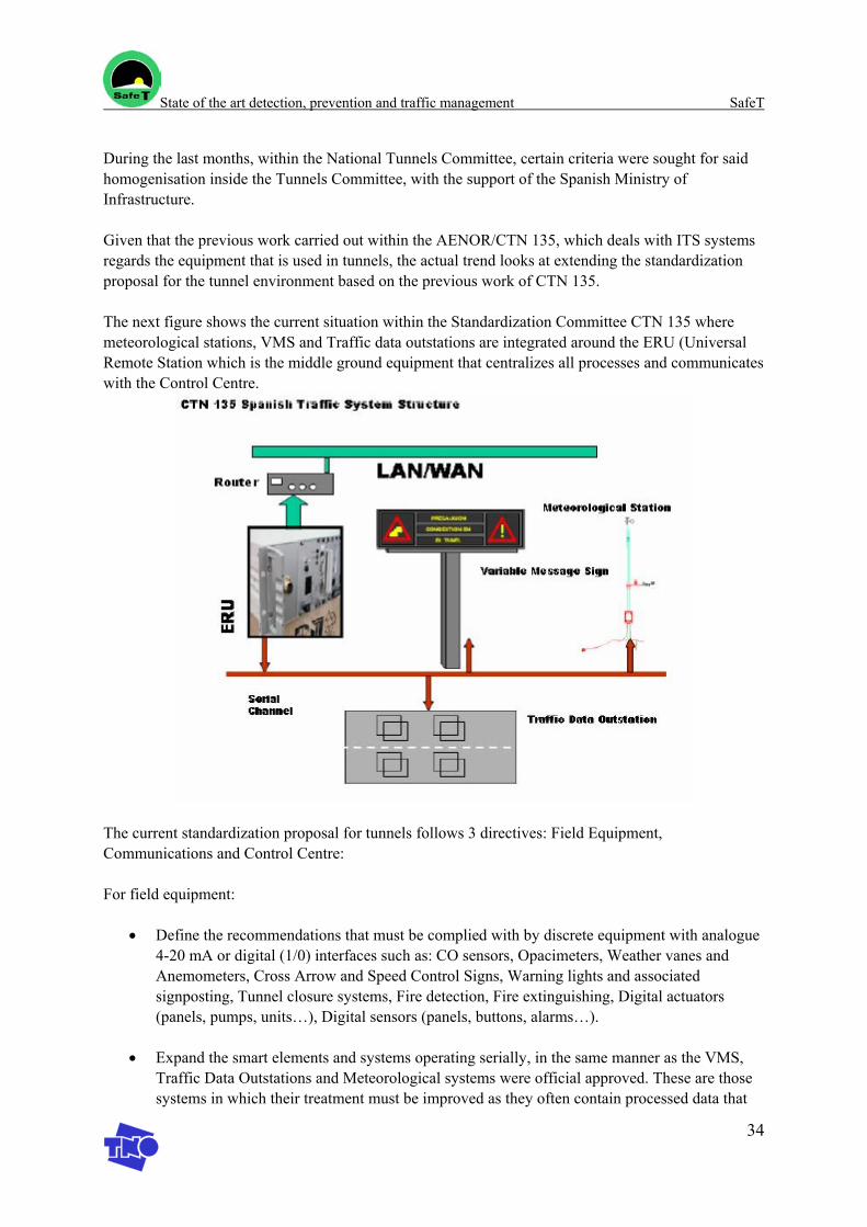
State of the art detection, prevention and traffic management SafeT
34
During the last months, within the National Tunnels Committee, certain criteria were sought for said homogenisation inside the Tunnels Committee, with the support of the Spanish Ministry of Infrastructure.
Given that the previous work carried out within the AENOR/CTN 135, which deals with ITS systems regards the equipment that is used in tunnels, the actual trend looks at extending the standardization proposal for the tunnel environment based on the previous work of CTN 135.
The next figure shows the current situation within the Standardization Committee CTN 135 where meteorological stations, VMS and Traffic data outstations are integrated around the ERU (Universal Remote Station which is the middle ground equipment that centralizes all processes and communicates with the Control Centre.
The current standardization proposal for tunnels follows 3 directives: Field Equipment, Communications and Control Centre:
For field equipment:
• Define the recommendations that must be complied with by discrete equipment with analogue 4-20 mA or digital (1/0) interfaces such as: CO sensors, Opacimeters, Weather vanes and Anemometers, Cross Arrow and Speed Control Signs, Warning lights and associated signposting, Tunnel closure systems, Fire detection, Fire extinguishing, Digital actuators (panels, pumps, units…), Digital sensors (panels, buttons, alarms…).
• Expand the smart elements and systems operating serially, in the same manner as the VMS,
Traffic Data Outstations and Meteorological systems were official approved. These are those systems in which their treatment must be improved as they often contain processed data that
State of the art detection, prevention and traffic management SafeT
35
cannot be easily dealt with as input/output data. These systems particularly include: Control and fire extinguishing exchanges in technical rooms, Smart fire detection systems (Fibro laser, Cable with sensors), Traffic light regulators, Access control systems, Electrical parameter measuring systems, Distributed input/output systems. Included in this concept are PLCs.
• Define the demands to be met by other systems not associated to data: CCTV cameras, SOS,
Public Address system, etc.
For the communications system:
• Expand the communications protocol of the Remote Station and open it up to different types of physical interfaces
• Define the adaptation of the remote station and its interfaces to different physical means of transmission through copper, fibre or wireless: SDH, ATM, ISDN, Gigabit etc.
For the Control Centre
• Define the functions demanded from the control centre in terms of automatic, semiautomatic or manual exploitation criteria. Establish the parameters required from the configuration of data and characterization of equipment, associated parameters, events, etc.
• Establish the criteria for information exchange between centres with expansion to tunnel systems
This extensive work that remains to be done by the standardization body, (tunnel committee) may be positively affected by the recommendations resulting from SafeT as this will clearly have an influence of the design of the equipment, software and architectures.
7.10 Exploitation aspects
At present national regulations such as IOS 98, FR 2000-63 and the international recommendations (i.e. PIARC) establish the need of a Tunnel Management Manual or Operations Manual as the reference document that serves to define the measures and actions concerning operations.
The Operations Manual is established following those recommendations and particularly for each tunnel. In relation to the traffic management and the detection and prevention aspects protocols must be defined during:
Normal operating conditions Emergency conditions, incidents and accidents Maintenance operations Transport of dangerous goods
Current exploitation manuals include a description of the protocols to be followed by the operators for the classified incidents and operations within the above categories.
State of the art detection, prevention and traffic management SafeT
36
7.11 Conclusions
We have seen in this document that there are recommendations for the type of equipment that is to be installed in a tunnel even though this is not harmonized in the existing national regulations. The international recommendations by PIARC, UN-EC and the several national regulations have represented an input towards to the EC directive proposal that includes aspects relative to the equipment within this first attempt to harmonize tunnel safety in all its aspects.
While the directive represents a first step ahead for the unification of all safety aspects, it is also certain that it is yet incomplete in relation to the installation of equipment, its emplacement and its use.
There is therefore a gap to be covered through SafeT in order to analyse and issue recommendations to extend the scope of the directive towards useful indications that can be more specific in terms of the equipment that needs to be used, its emplacement and operating recommendations.
State of the art detection, prevention and traffic management SafeT
37
8. Discussion
Due to the fact that, for both incident prevention and traffic management the requirements are very diverse and in some cases lacking it is of the most importance that a standard package of minimal incident prevention and traffic management requirements is being lined up.
State of the art detection, prevention and traffic management SafeT
38
9. References
[1] VRC 03 024, versie 2 definitief, d.d. 17-9-03
[2] Directive 2004/54/EC on minimum safety requirements for tunnels in the Trans-European Road Network, Brussels, 29 April 2004.
[3] FIT is a European Thematic Network on Fire in Tunnels. FIT provides a European platform for dissemination and information of up-to-date knowledge and research on Fire & Tunnels. FIT represents 33 members from 12 European Countries. http://www.etnfit.net/. Consulted document: Listing of consulted guidelines.
[4] Veiligheid ondergrondse infrastructuur, Detectiesystemen, C. Mulder, Utrecht, 4 december 2002
[5] Safety in the Sodra Lanken tunnel in Stockholm, Sweden; T. Sandman; Proceedings of the Fourth International conference on Safety in Road and Rail Tunnels; 2-6 april 2001; Madrid, Spain; Organised an sponsored by the University of Dundee an Independent Technical Conferences Ltd.; edited by Alan E. Vardy; ISBN 1901808173
[6] Information on Section control: http://www.asfinag.at/ under “sicherheit” and then “Section Control”.
[7] An emergency broadcasting system in road tunnels using the VICS navigation devices; I. Nakahori, S. Hashimoto, K. Murakami; Sohatsu Systems Laboratory Inc, Japan; Proceedings of the Fifth International Conference on Safety in Road and Rail Tunnels, 6-10 October 2003, Marseille, France. Organised and Sponsored by the University of Dundee and Tunnel Management International. In general: D•A•R•T•S, Durable and Reliable Tunnel Structures, Identification and quantification of Hazards, Project GRD1-25633, Document DARTS/4.1, February 2002
[1] WP3 Report: Fire safe Design, Road Tunnels, Public Draft document, FIT European Thematic Network, September 2003, available at http://www.etnfit.net
[2] Best Practice Manual on Operation and Maintenance of Tunnels, PIARC C5: Road tunnel operation, Working group 1: Operations, December 2003
[3] Tunnel standard description, SICE: internal document
[4] Proposal for a Directive of the European Parliament and of the council on minimum safety requirements for tunnels in the Trans-European Road Network, European Commission, December 2002
State of the art detection, prevention and traffic management SafeT
39
[5] Integral Unification of tunnels monitoring, paper 2211, Lorenzo Espinosa Román, Proceedings of the 10th World Congress on Intelligent Transportation Systems and Services , November 2003, Madrid
[6] Túneles: equipamiento y seguridad, Extraordinario 2000 Túneles, Revista Carreteras
[7] Seguridad en los túneles de carreteras, RACE/RACC, Seguritecnia, septiembre 2001.
[8] La seguridad en los túneles y el factor humano, Rafael López Guarga, Revista Rutas
[9] El transporte de mercancías peligrosas a través de los túneles de carretera, Resumen del proyecto de investigación conjunta OCDE, PIARC, Jesús Leal Bermejo et al, Revista Rutas
[10] NPRA, comments of Mr. Amundsen, email 18-10-2004.
SafeT
Work package 1 Task 1.3
D1.3 report
State of the art consequence mitigation
Version: April 2005 Author: I.J.M. Trijssenaar-Buhre
State of the art consequence mitigation SafeT
2
Table of contents
1. Introduction............................................................................................................................. 3 1.1 Scope of Task 1.3 .................................................................................................... 3 1.2 What is consequence mitigation? ............................................................................ 4
2. Evacuation / intervention management................................................................................... 6 2.1 Process analysis of incident management, self-rescue and
emergency operation in tunnels............................................................................... 6 2.1.1 Incident management .................................................................................. 6 2.1.2 Self-rescue process...................................................................................... 7 2.1.3 Emergency operation................................................................................... 8
2.2 Discussion: from process analysis to guidelines ................................................... 13
3. Training of operators and rescue personnel .......................................................................... 14 3.1 GAMMA-EC......................................................................................................... 14
3.1.1 Context ...................................................................................................... 14 3.1.2 Goal ........................................................................................................... 14 3.1.3 Results ....................................................................................................... 14
3.2 Demonstrator of GATE training programme ........................................................ 15 3.3 Virtual fires............................................................................................................ 15 3.4 ADMS ................................................................................................................... 15
4. Technical measures ............................................................................................................... 17 4.1 Introduction ........................................................................................................... 17 4.2 Consequence mitigating measures in stage II: “development of
the accident” .......................................................................................................... 17 4.3 Consequence mitigating measures in stage III: “Detection” ................................. 18 4.4 Consequence mitigating measures in stage IV: “Egress”...................................... 18 4.5 Consequence mitigating measures in stage V: “Emergency
response” ............................................................................................................... 19 4.6 Overview of technical measures............................................................................ 19 4.7 Discussion.............................................................................................................. 22
5. References............................................................................................................................. 23
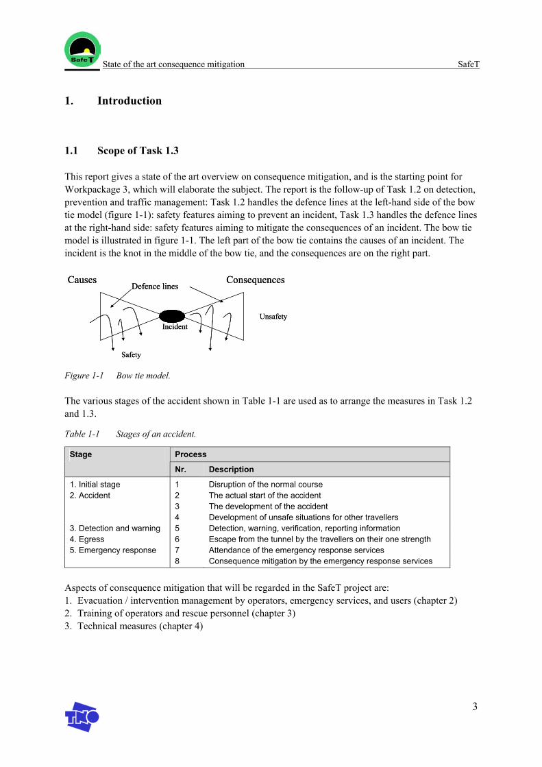
State of the art consequence mitigation SafeT
3
1. Introduction
1.1 Scope of Task 1.3
This report gives a state of the art overview on consequence mitigation, and is the starting point for Workpackage 3, which will elaborate the subject. The report is the follow-up of Task 1.2 on detection, prevention and traffic management: Task 1.2 handles the defence lines at the left-hand side of the bow tie model (figure 1-1): safety features aiming to prevent an incident, Task 1.3 handles the defence lines at the right-hand side: safety features aiming to mitigate the consequences of an incident. The bow tie model is illustrated in figure 1-1. The left part of the bow tie contains the causes of an incident. The incident is the knot in the middle of the bow tie, and the consequences are on the right part.
Causes Consequences
Unsafety
Safety
Defence lines
Incident
Causes Consequences
Unsafety
Safety
Defence lines
Incident
Figure 1-1 Bow tie model.
The various stages of the accident shown in Table 1-1 are used as to arrange the measures in Task 1.2 and 1.3.
Table 1-1 Stages of an accident.
Process Stage
Nr. Description
1. Initial stage 1 Disruption of the normal course 2. Accident 2 The actual start of the accident 3 The development of the accident 4 Development of unsafe situations for other travellers 3. Detection and warning 5 Detection, warning, verification, reporting information 4. Egress 6 Escape from the tunnel by the travellers on their one strength 5. Emergency response 7 Attendance of the emergency response services 8 Consequence mitigation by the emergency response services
Aspects of consequence mitigation that will be regarded in the SafeT project are: 1. Evacuation / intervention management by operators, emergency services, and users (chapter 2) 2. Training of operators and rescue personnel (chapter 3) 3. Technical measures (chapter 4)
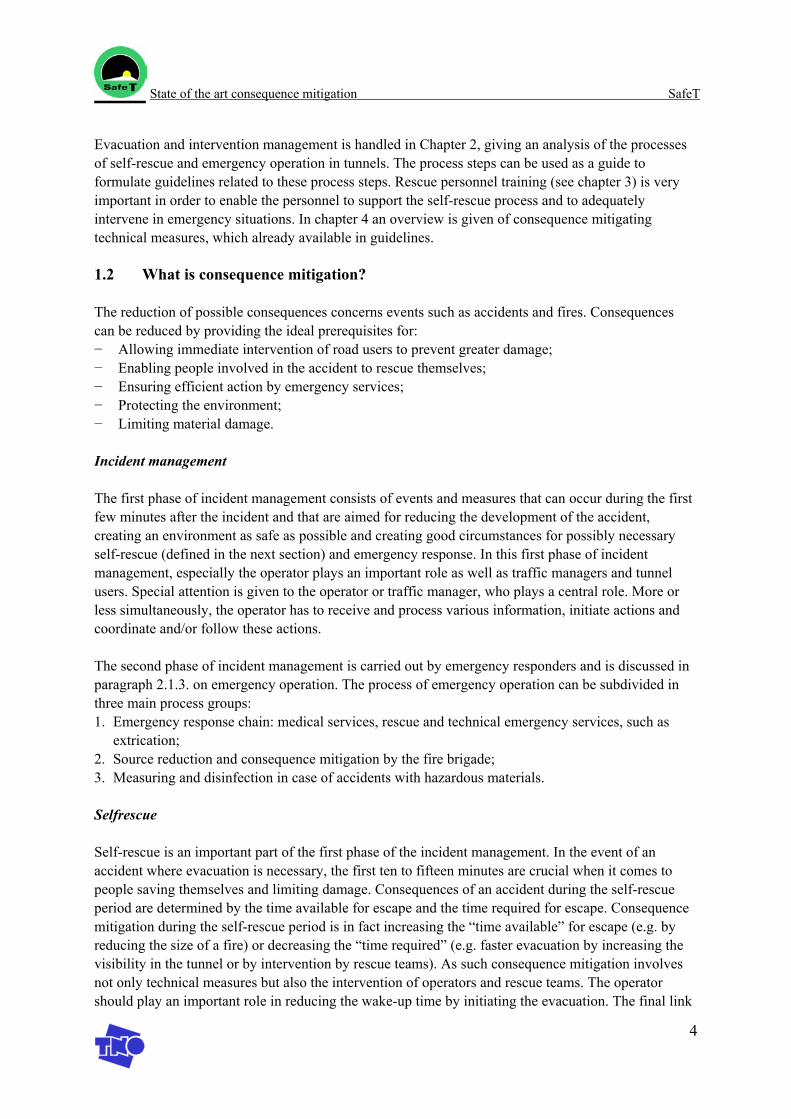
State of the art consequence mitigation SafeT
4
Evacuation and intervention management is handled in Chapter 2, giving an analysis of the processes of self-rescue and emergency operation in tunnels. The process steps can be used as a guide to formulate guidelines related to these process steps. Rescue personnel training (see chapter 3) is very important in order to enable the personnel to support the self-rescue process and to adequately intervene in emergency situations. In chapter 4 an overview is given of consequence mitigating technical measures, which already available in guidelines.
1.2 What is consequence mitigation?
The reduction of possible consequences concerns events such as accidents and fires. Consequences can be reduced by providing the ideal prerequisites for: − Allowing immediate intervention of road users to prevent greater damage; − Enabling people involved in the accident to rescue themselves; − Ensuring efficient action by emergency services; − Protecting the environment; − Limiting material damage.
Incident management
The first phase of incident management consists of events and measures that can occur during the first few minutes after the incident and that are aimed for reducing the development of the accident, creating an environment as safe as possible and creating good circumstances for possibly necessary self-rescue (defined in the next section) and emergency response. In this first phase of incident management, especially the operator plays an important role as well as traffic managers and tunnel users. Special attention is given to the operator or traffic manager, who plays a central role. More or less simultaneously, the operator has to receive and process various information, initiate actions and coordinate and/or follow these actions.
The second phase of incident management is carried out by emergency responders and is discussed in paragraph 2.1.3. on emergency operation. The process of emergency operation can be subdivided in three main process groups: 1. Emergency response chain: medical services, rescue and technical emergency services, such as
extrication; 2. Source reduction and consequence mitigation by the fire brigade; 3. Measuring and disinfection in case of accidents with hazardous materials.
Selfrescue
Self-rescue is an important part of the first phase of the incident management. In the event of an accident where evacuation is necessary, the first ten to fifteen minutes are crucial when it comes to people saving themselves and limiting damage. Consequences of an accident during the self-rescue period are determined by the time available for escape and the time required for escape. Consequence mitigation during the self-rescue period is in fact increasing the “time available” for escape (e.g. by reducing the size of a fire) or decreasing the “time required” (e.g. faster evacuation by increasing the visibility in the tunnel or by intervention by rescue teams). As such consequence mitigation involves not only technical measures but also the intervention of operators and rescue teams. The operator should play an important role in reducing the wake-up time by initiating the evacuation. The final link

State of the art consequence mitigation SafeT
5
in the chain of consequence mitigation is the intervention of rescue services. Especially the communication between operator and rescue services has shown to be a critical element in emergency situations.
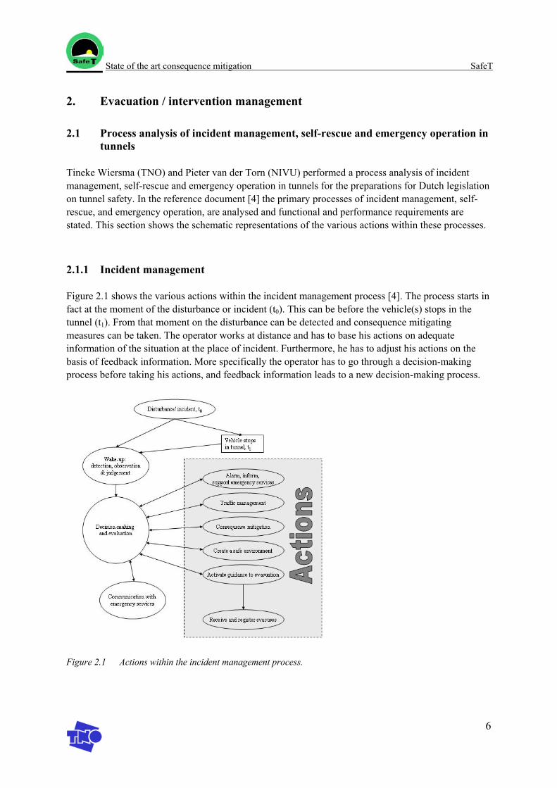
State of the art consequence mitigation SafeT
6
2. Evacuation / intervention management
2.1 Process analysis of incident management, self-rescue and emergency operation in tunnels
Tineke Wiersma (TNO) and Pieter van der Torn (NIVU) performed a process analysis of incident management, self-rescue and emergency operation in tunnels for the preparations for Dutch legislation on tunnel safety. In the reference document [4] the primary processes of incident management, self-rescue, and emergency operation, are analysed and functional and performance requirements are stated. This section shows the schematic representations of the various actions within these processes.
2.1.1 Incident management
Figure 2.1 shows the various actions within the incident management process [4]. The process starts in fact at the moment of the disturbance or incident (t0). This can be before the vehicle(s) stops in the tunnel (t1). From that moment on the disturbance can be detected and consequence mitigating measures can be taken. The operator works at distance and has to base his actions on adequate information of the situation at the place of incident. Furthermore, he has to adjust his actions on the basis of feedback information. More specifically the operator has to go through a decision-making process before taking his actions, and feedback information leads to a new decision-making process.
Figure 2.1 Actions within the incident management process.
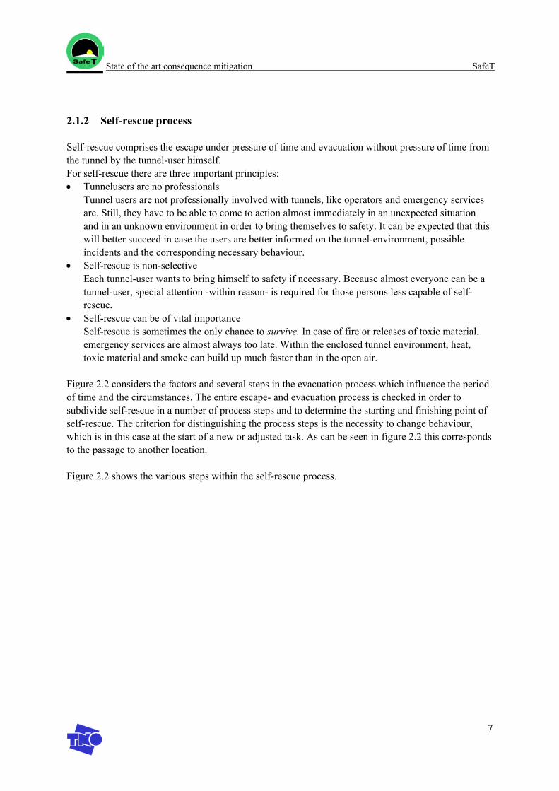
State of the art consequence mitigation SafeT
7
2.1.2 Self-rescue process
Self-rescue comprises the escape under pressure of time and evacuation without pressure of time from the tunnel by the tunnel-user himself. For self-rescue there are three important principles: • Tunnelusers are no professionals
Tunnel users are not professionally involved with tunnels, like operators and emergency services are. Still, they have to be able to come to action almost immediately in an unexpected situation and in an unknown environment in order to bring themselves to safety. It can be expected that this will better succeed in case the users are better informed on the tunnel-environment, possible incidents and the corresponding necessary behaviour.
• Self-rescue is non-selective Each tunnel-user wants to bring himself to safety if necessary. Because almost everyone can be a tunnel-user, special attention -within reason- is required for those persons less capable of self-rescue.
• Self-rescue can be of vital importance Self-rescue is sometimes the only chance to survive. In case of fire or releases of toxic material, emergency services are almost always too late. Within the enclosed tunnel environment, heat, toxic material and smoke can build up much faster than in the open air.
Figure 2.2 considers the factors and several steps in the evacuation process which influence the period of time and the circumstances. The entire escape- and evacuation process is checked in order to subdivide self-rescue in a number of process steps and to determine the starting and finishing point of self-rescue. The criterion for distinguishing the process steps is the necessity to change behaviour, which is in this case at the start of a new or adjusted task. As can be seen in figure 2.2 this corresponds to the passage to another location.
Figure 2.2 shows the various steps within the self-rescue process.
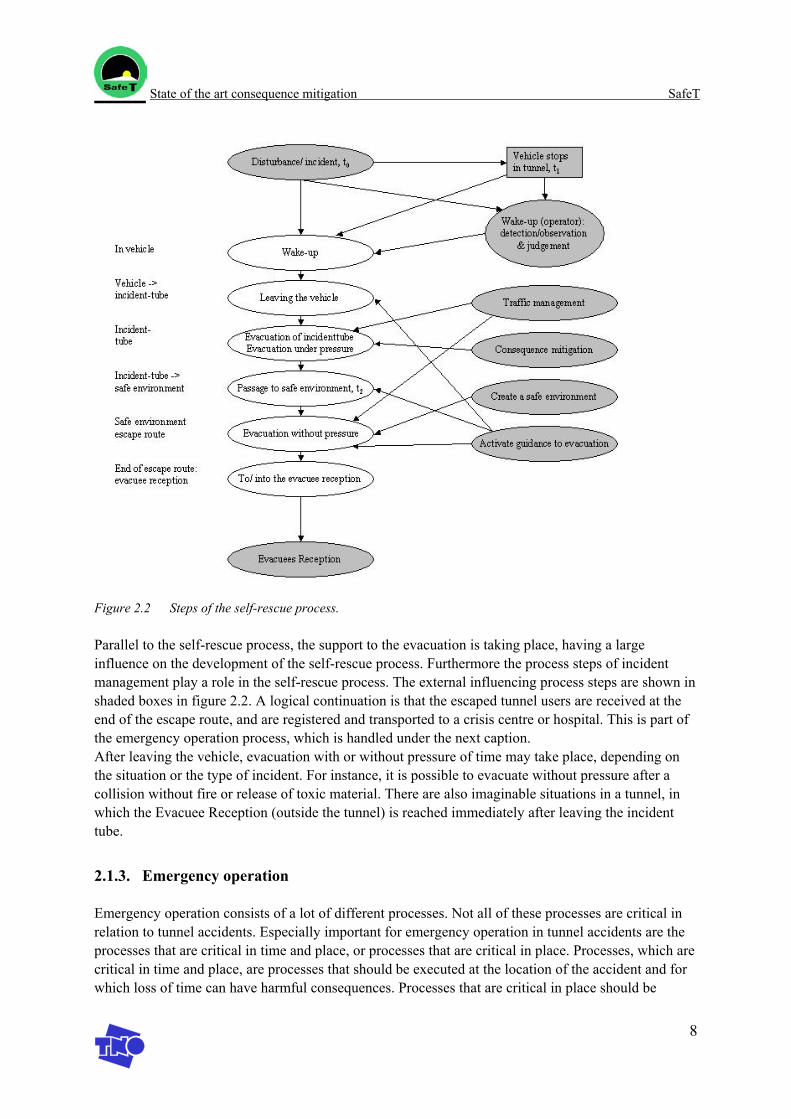
State of the art consequence mitigation SafeT
8
Figure 2.2 Steps of the self-rescue process.
Parallel to the self-rescue process, the support to the evacuation is taking place, having a large influence on the development of the self-rescue process. Furthermore the process steps of incident management play a role in the self-rescue process. The external influencing process steps are shown in shaded boxes in figure 2.2. A logical continuation is that the escaped tunnel users are received at the end of the escape route, and are registered and transported to a crisis centre or hospital. This is part of the emergency operation process, which is handled under the next caption. After leaving the vehicle, evacuation with or without pressure of time may take place, depending on the situation or the type of incident. For instance, it is possible to evacuate without pressure after a collision without fire or release of toxic material. There are also imaginable situations in a tunnel, in which the Evacuee Reception (outside the tunnel) is reached immediately after leaving the incident tube.
2.1.3. Emergency operation
Emergency operation consists of a lot of different processes. Not all of these processes are critical in relation to tunnel accidents. Especially important for emergency operation in tunnel accidents are the processes that are critical in time and place, or processes that are critical in place. Processes, which are critical in time and place, are processes that should be executed at the location of the accident and for which loss of time can have harmful consequences. Processes that are critical in place should be
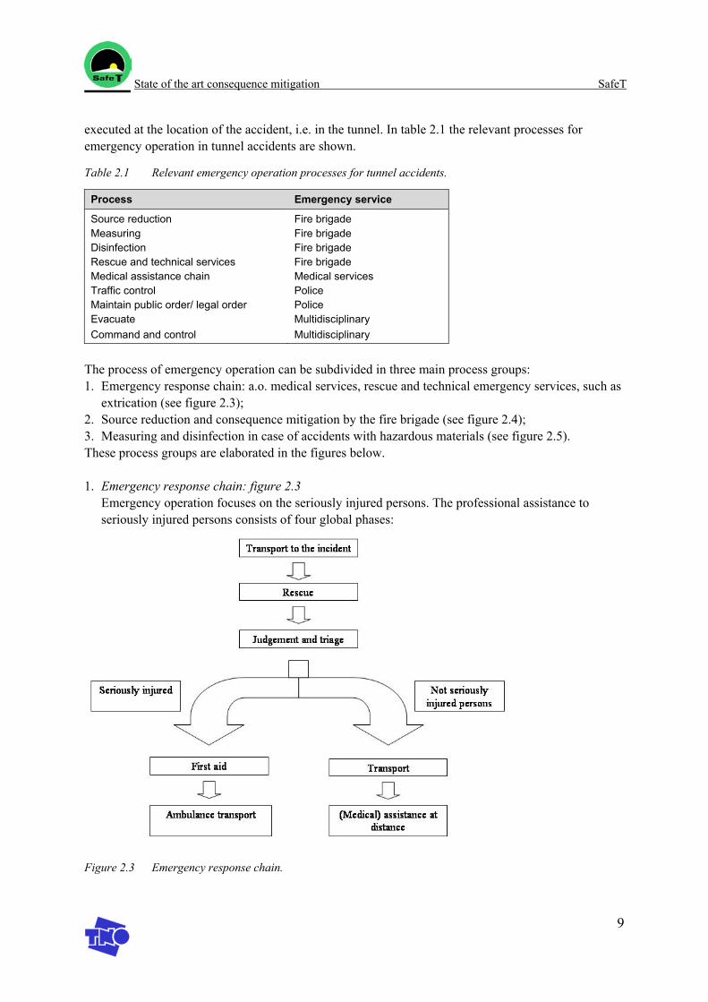
State of the art consequence mitigation SafeT
9
executed at the location of the accident, i.e. in the tunnel. In table 2.1 the relevant processes for emergency operation in tunnel accidents are shown.
Table 2.1 Relevant emergency operation processes for tunnel accidents.
Process Emergency service
Source reduction Fire brigade Measuring Fire brigade Disinfection Fire brigade Rescue and technical services Fire brigade Medical assistance chain Medical services Traffic control Police Maintain public order/ legal order Police Evacuate Multidisciplinary Command and control Multidisciplinary
The process of emergency operation can be subdivided in three main process groups: 1. Emergency response chain: a.o. medical services, rescue and technical emergency services, such as
extrication (see figure 2.3); 2. Source reduction and consequence mitigation by the fire brigade (see figure 2.4); 3. Measuring and disinfection in case of accidents with hazardous materials (see figure 2.5). These process groups are elaborated in the figures below. 1. Emergency response chain: figure 2.3
Emergency operation focuses on the seriously injured persons. The professional assistance to seriously injured persons consists of four global phases:
Figure 2.3 Emergency response chain.
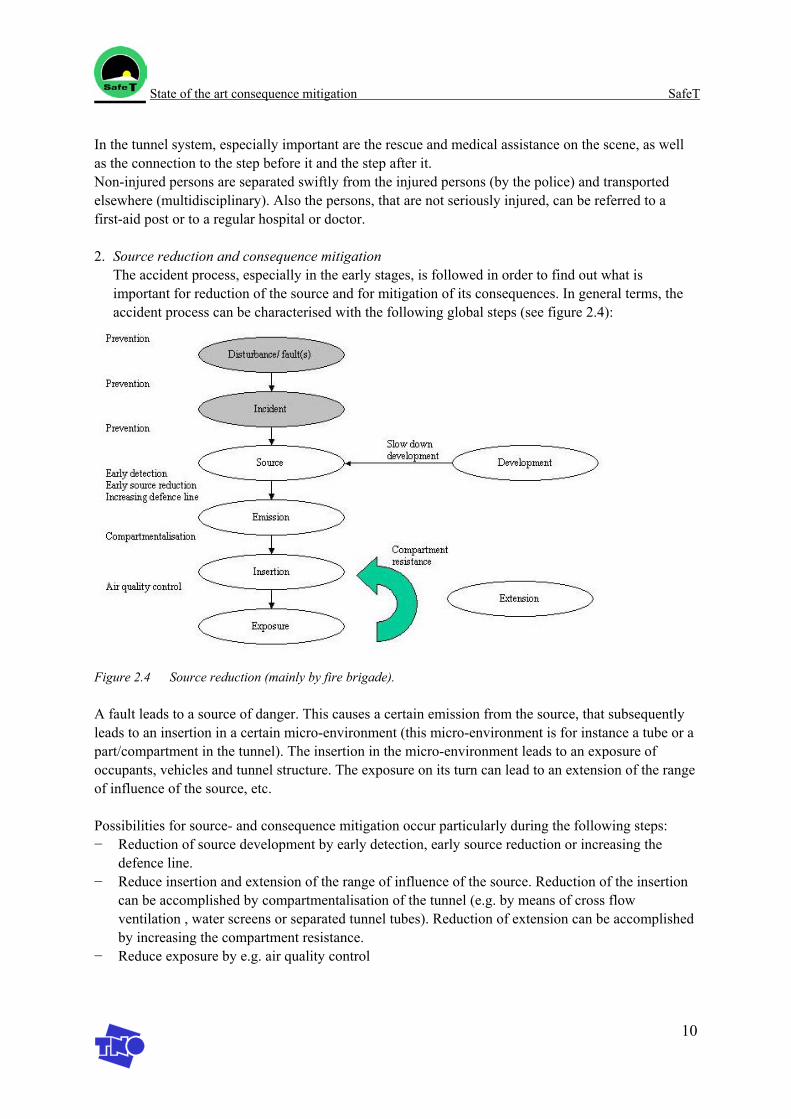
State of the art consequence mitigation SafeT
10
In the tunnel system, especially important are the rescue and medical assistance on the scene, as well as the connection to the step before it and the step after it. Non-injured persons are separated swiftly from the injured persons (by the police) and transported elsewhere (multidisciplinary). Also the persons, that are not seriously injured, can be referred to a first-aid post or to a regular hospital or doctor. 2. Source reduction and consequence mitigation
The accident process, especially in the early stages, is followed in order to find out what is important for reduction of the source and for mitigation of its consequences. In general terms, the accident process can be characterised with the following global steps (see figure 2.4):
Figure 2.4 Source reduction (mainly by fire brigade).
A fault leads to a source of danger. This causes a certain emission from the source, that subsequently leads to an insertion in a certain micro-environment (this micro-environment is for instance a tube or a part/compartment in the tunnel). The insertion in the micro-environment leads to an exposure of occupants, vehicles and tunnel structure. The exposure on its turn can lead to an extension of the range of influence of the source, etc.
Possibilities for source- and consequence mitigation occur particularly during the following steps: − Reduction of source development by early detection, early source reduction or increasing the
defence line. − Reduce insertion and extension of the range of influence of the source. Reduction of the insertion
can be accomplished by compartmentalisation of the tunnel (e.g. by means of cross flow ventilation , water screens or separated tunnel tubes). Reduction of extension can be accomplished by increasing the compartment resistance.
− Reduce exposure by e.g. air quality control
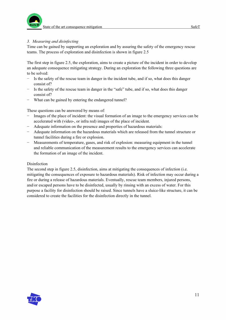
State of the art consequence mitigation SafeT
11
3. Measuring and disinfecting Time can be gained by supporting an exploration and by assuring the safety of the emergency rescue teams. The process of exploration and disinfection is shown in figure 2.5
The first step in figure 2.5, the exploration, aims to create a picture of the incident in order to develop an adequate consequence mitigating strategy. During an exploration the following three questions are to be solved: − Is the safety of the rescue team in danger in the incident tube, and if so, what does this danger
consist of? − Is the safety of the rescue team in danger in the “safe” tube, and if so, what does this danger
consist of? − What can be gained by entering the endangered tunnel?
These questions can be answered by means of: − Images of the place of incident: the visual formation of an image to the emergency services can be
accelerated with (video-, or infra red) images of the place of incident. − Adequate information on the presence and properties of hazardous materials: − Adequate information on the hazardous materials which are released from the tunnel structure or
tunnel facilities during a fire or explosion. − Measurements of temperature, gases, and risk of explosion: measuring equipment in the tunnel
and reliable communication of the measurement results to the emergency services can accelerate the formation of an image of the incident.
Disinfection The second step in figure 2.5, disinfection, aims at mitigating the consequences of infection (i.e. mitigating the consequences of exposure to hazardous materials). Risk of infection may occur during a fire or during a release of hazardous materials. Eventually, rescue team members, injured persons, and/or escaped persons have to be disinfected, usually by rinsing with an excess of water. For this purpose a facility for disinfection should be raised. Since tunnels have a sluice-like structure, it can be considered to create the facilities for the disinfection directly in the tunnel.
State of the art consequence mitigation SafeT
12
Figure 2.5 Steps of the process of measuring and disinfecting.
State of the art consequence mitigation SafeT
13
2.2 Discussion: from process analysis to guidelines
In the reference document [4] the primary processes of incident management, self-rescue and emergency operation are analysed and functional and performance requirements are stated. These functional and performance requirements can be guidelines on themselves or can be translated in technical or organisational measures. Also for the SafeT project, the process steps can be used as a guide to formulate guidelines related to these process steps. The requirements formulated in the reference documents apply at least to the Dutch emergency operation in tunnels. In Workpackage 3 it should be evaluated in which extent these (Dutch) requirements can be used for European guidelines, using additional knowledge of requirements and guidelines in other (non-) European countries. Interesting reference documents for Workpackage 3 are: − Process analysis [4] − Overview of Dutch basic safety measures [VRC] − Best practice for safe operation and fire response management, FIT WP4 [3]
State of the art consequence mitigation SafeT
14
3. Training of operators and rescue personnel
Rescue personnel and operator training is very important in order to enable the personnel to support the self-rescue process and to adequately intervene in emergency situations. In this chapter several tools for the training of operators and rescue personnel are handled. The tools considered are GATE, GAMMA-EC, Virtual Fires, and ADMS.
3.1 GAMMA-EC
GAMMA-EC is an education and training tool for disaster management. GAMMA-EC stands for: Gaming And MultiMedia Applications for Environmental Crisis management training.
3.1.1 Context
Real-life exercises with respect to environmental emergency planning can only be executed on a limited scale. Otherwise, these exercises are too expensive or too dangerous for the surrounding and the environment. Therefore, emergency managers are trained by ‘exercises on paper’ and/or roleplaying games. These exercises, however, require a lot of preparation time; so, scenarios are hardly ever updated. As a consequence of this the emergency managers are not trained as well as they should be.
3.1.2 Goal
The goal of the EC project GAMMA-EC is to develop computer-assisted tools to improve the education and training of disaster managers. With the help of such tools the preparation time of training sessions will be shortened because the training scenarios can easily be developed or changed. The motivation of the trainees will increase because the scenarios can be tailored for the own organisation and the geographical area of the emergency staff. Furthermore, the advantage of computer assistance is that the computer -instead of the training staff- can calculate the effects of decisions that will be made by the students. So, during training sessions the training staff gets more time to concentrate on other aspects such as the evaluation of a training session, psychological aspects, team behaviour, etc.
3.1.3 Results
The project results in a set of tools, consisting of: 1. a multimedia program for individual education of disaster managers 2. an interactive simulation program (crisis game) for training disaster managers simultaneously as a
team. In addition to these tools generic pedagogical directives are developed for designing scenarios and for assessing team member performance in decision-making and exchanging information. All tools are developed and validated in co-operation with future end-users (fire-academies, disaster control managers). During the project two applications are worked out to show the GAMMA-EC concept works: large-scale forest fires and chemical accidents.
For more information: www.tno.nl/instit/fel/gamma_ec
State of the art consequence mitigation SafeT
15
3.2 Demonstrator of GATE training programme
A demonstrator of an education module for tunnel operators was made in 2003 within the framework of the EU-project GATE. The purpose of the education module is to train the operators in procedures, which they should follow in case of incidents and calamities. The project is part of the development of the ME-T programme: a multimedia tool for individual education and training.
ME-T is a training programme with the emphasis on choosing the right procedures in various situations and carry out the consecutive actions correctly. The student learns to solve incident and emergency situations by means of scenarios.
No special training programmes are available that are specialised in the tasks of tunnel operators. Tunnel operators guard the traffic situation in the tunnel and are the first to be addressed by road users, who are having problems in the tunnel and/or who are involved in an accident. An adequate reaction of the tunnel operator to manage the traffic situation in case of obstacles or accidents can prevent the disturbance from escalating. Self-rescue is important in preventing high amounts of victims due to calamities in tunnels. Tunnel operators can play an important role in guiding the evacuation of the tunnel occupants and in operating for instance the ventilation systems to influence the air quality. Therefore it is especially important that they obtain the basic knowledge relevant for this role and that they can use this basic knowledge in case of emergency situations. For the training of the operators, simulators can be located in the control room, so operators can regularly update and refresh their knowledge.
The demonstrator shows the possibilities of the education modules by means of two scenarios. The objective of the scenarios is to solve the outlined problem. The knowledge necessary to make the right choices is also available in the GATE demonstrator. For more information: www.tno.nl/instit/fel/gate
3.3 Virtual fires
The aim of the project is to develop a simulator that allows to train fire fighters in the efficient mitigation of fires in a tunnel, using a computer generated virtual environment. This will be a cheap and environmentally friendly alternative to real fire fighting exercises involving burning fuel in a disused tunnel. The simulator can also be used to test the fire safety of a tunnel and the influence of mitigating measures (ventilation, fire suppression etc.) on it's fire safety level. The project VIRTUALFIRES is being funded by the European Commission and involves eight partners from five European countries.
For more information: www.virtualfires.org
3.4 ADMS
Advanced Disaster Management System (ADMS) is a virtual reality-based training system that provides emergency responders an opportunity to develop skills in command, control, mitigation and emergency communication. Provided to public safety and emergency response organizations, airports and government agencies, ADMS simulates emergency incidents such as aircraft accidents, terrorist
State of the art consequence mitigation SafeT
16
acts, hazardous material spills, airfield incursions, fires and natural disasters for the purposes of planning, training, testing and validating.
Emergency Responders
Emergency responders (Police, HAZMAT, Emergency medical) have a difficult task in these times of uncertainty. ADMS™ provides a platform for emergency responders to test their skills in a safe and efficient manner. By using simulation emergency responders can use different scenarios and change environmental factors to optimize the most of their training.
NIBRA selected ADMS™ to develop and deliver comprehensive training programs that will allow fire officers, incident managers and other emergency response personnel to work together and train as an "integrated team". Prior to ADMS™ technology, training was only possible through live mock up drills, which although useful to increase awareness, are expensive and provide limited training effectiveness.
The ADMS™ provides the most effective means of saving lives and mitigating losses. The interactive capability of ADMS™ Intelligent VR technology allows the exercise to be driven by the decision-making process, providing for a way to develop skills and enhance the competency level.
State of the art consequence mitigation SafeT
17
4. Technical measures
4.1 Introduction
This section gives an overview and description of technical measures [2] subdivided into the respective stages of an accident (see the section 0 for an explanation of the stages): 1. The development of the accident (stage II) 2. Detection (stage III) 3. Egress (stage IV) 4. Emergency response (stage V)
Consequence mitigating measures differ for the various types of accidents. In case of a broken down vehicle the consequence mitigating measures aim to remove the vehicle as quickly as possible. In case of a fire relevant measures are for example fire extinguishers, ventilation, and measures for a fast evacuation. Accidents can be subdivided in the following categories: − Broken down vehicle − Collision with material damage, no victims − Accident with victims − Fire − Explosion − Release of hazardous material
Table 4.1 in paragraph 4.6 shows which measures are generally applicable, and which measures are specific for one or more of the accident categories mentioned above
4.2 Consequence mitigating measures in stage II: “development of the accident”
Power supply In case of an emergency, it is necessary to have a reliable supply of power to operate the safety systems such as ventilation, lighting, information and communication systems etc. [2]
Structure & equipment, response to incident The tunnel structure and the equipment should be able to resist the fire, (small) explosion or exposure to certain hazardous materials, and should perform safely for a period sufficient for the evacuation of the tunnel users. In addition the structure and the equipment should enable the consequence mitigation, such as fire fighting. Furthermore the structure and the equipment should be designed with the aim of minimising the economical damage from the incidents [2].
Smoke control ventilation Ventilation of smoke and hazardous gases or vapours is a very important safety measure both for the evacuation of tunnel users and for assistance to the emergency operation. The arrangement of the ventilation system is dependent on the traffic (contraflow or unidirectional traffic) and the length of the tunnel [2].
State of the art consequence mitigation SafeT
18
Drainage of hazardous/flammable liquids If hazardous liquids are spilled in a tunnel there is a risk that the spill can be spread through the tunnel or ignited and cause a serious fire. If the tunnel is well drained and the hazardous liquids are collected in a system suitable for the purpose, this risk can be reduced [2].
Fire suppression (technical equipment) In case of a fire in the tunnel it will be most efficient to fight the fire in the initial part of the fire. Fire fighting equipment may be brought with the vehicles, but if this equipment is not available or not sufficient, first aid fire fighting equipment in the tunnel can be used (similar to buildings it may also be considered to have sprinklers or deluge system in the tunnel). If this equipment is also not sufficient there should be facilities for the fire fighting by external assistance by the fire brigade or similar [2].
4.3 Consequence mitigating measures in stage III: “Detection”
Communication and alarm system It is important that the OP-room and the control system have information about the occurrence of an emergency. The information is achieved by surveillance of the tunnel and by various communication systems. The communication can be in terms of automatic systems triggered by using equipment monitoring air quality or incident detection in addition it can be manual by e.g. alarm push bottom or by emergency telephone. Redundancy in the detection system is necessary in order to achieve a high probability of the appropriate action to an emergency situation. Furthermore the communication system shall be used to instruct the affected tunnel users about what to do in the situation. This information may be given through the radio or information signage, while the users are still in their vehicles, or through the emergency telephone or in some cases through load speakers for users in the tunnel or in the shelters [2].
4.4 Consequence mitigating measures in stage IV: “Egress”
Emergency passenger exit for users The emergency exit for tunnel users are established with the purpose of having a safe haven in case of situations in the tunnel. The exits will mainly be used in case of a fire, explosion or release of hazardous material in the tunnel. The emergency exit can be connected to the adjacent traffic tube, to a dedicated escape tube or the open landscape. The connection can be direct or through a cross passage, shaft or similar. In some cases shelters are arranged as safe havens, where tunnel users can stay for some time [2].
Emergency exit and rescue access ventilation In the emergency exits there should be good conditions for resting in safety at least for some time. This may require ventilation at the exits. The ventilation can also improve the conditions for the rescue forces [2].
Lighting measures at portals In case of an emergency it is important to have sufficient lighting in the tunnel. The light will provide visibility for the possible evacuation and for the rescue operation. Additional marker lights may indicate the route to the exits. Also in the escape routes (cross passages, escape tunnel etc.) it will be necessary to have sufficient light in order to have an effective evacuation [2].
State of the art consequence mitigation SafeT
19
Signage (permanent/variable) There will be many types of signage in a road tunnel. The signage will partly have a preventive purpose (e.g. speed limits, restrictions to overtake, etc.) partly it will inform the tunnel users about the occurrence of an emergency situation and the information about what to do in the situation and control of the situation. In the present study focus is given to the mitigation measures, i.e. the latter part of the signage. Some signs may benefit both for prevention and mitigation, e.g. the information about the radio channel [2].
4.5 Consequence mitigating measures in stage V: “Emergency response”
Emergency access for rescue staff In case of an emergency, e.g. a fire or a severe accident, the rescue staff may not be able to access the accident site directly but may have to access through the adjacent tunnel or through shafts. The access from the adjacent tunnel may make it possible to drive the vehicles from tunnel to tunnel, or access may be for rescuers on foot only4 [2].
4.6 Overview of technical measures
Table 4.1 gives an overview of technical measures for consequence mitigation, which are available in present guidelines in (non-) European countries. The table shows, which basic measures are generally applicable, and which measures are specific for one or more of the accident categories. The basic measures are adequate for the incidents concerning broken down vehicles or concerning collisions with material damage, with or without victims.
4 Accessing the accident spot by foot might involve large logistic problems by carrying heavy materials
over long ways
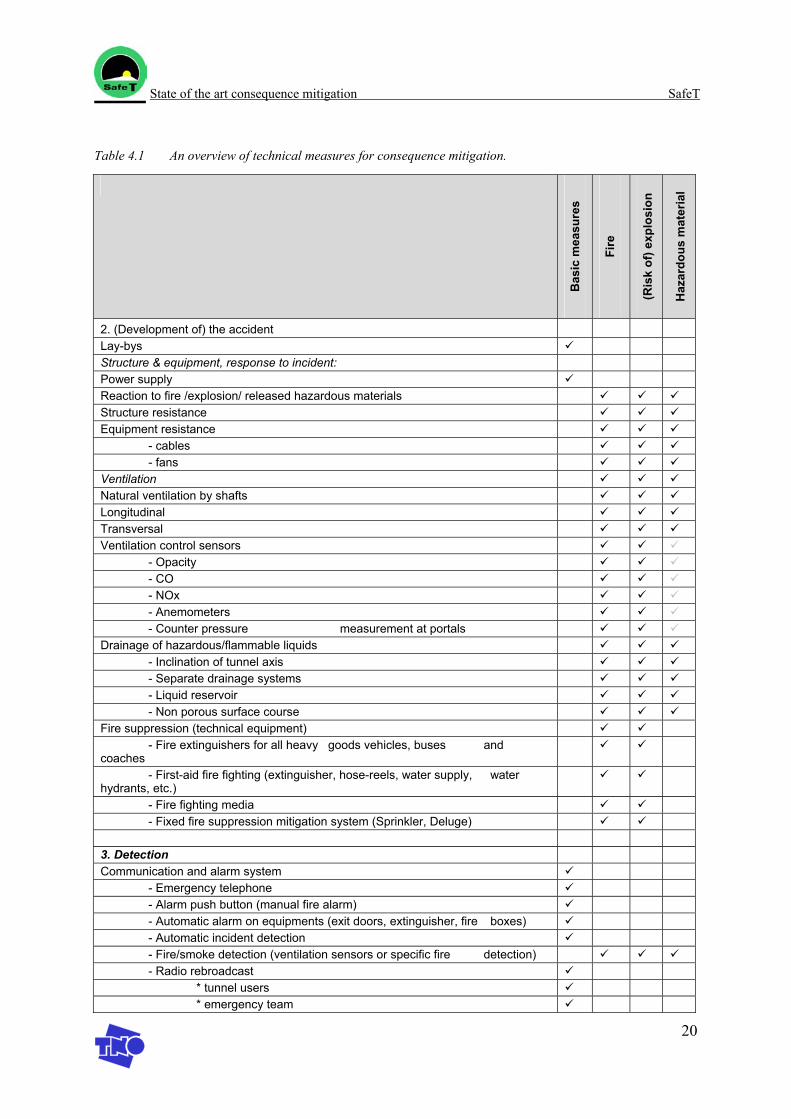
State of the art consequence mitigation SafeT
20
Table 4.1 An overview of technical measures for consequence mitigation.
Bas
ic m
easu
res
Fire
(Ris
k of
) exp
losi
on
Haz
ardo
us m
ater
ial
2. (Development of) the accident Lay-bys Structure & equipment, response to incident: Power supply Reaction to fire /explosion/ released hazardous materials Structure resistance Equipment resistance - cables - fans Ventilation Natural ventilation by shafts Longitudinal Transversal Ventilation control sensors - Opacity - CO - NOx - Anemometers - Counter pressure measurement at portals Drainage of hazardous/flammable liquids - Inclination of tunnel axis - Separate drainage systems - Liquid reservoir - Non porous surface course Fire suppression (technical equipment) - Fire extinguishers for all heavy goods vehicles, buses and coaches
- First-aid fire fighting (extinguisher, hose-reels, water supply, water hydrants, etc.)
- Fire fighting media - Fixed fire suppression mitigation system (Sprinkler, Deluge) 3. Detection Communication and alarm system - Emergency telephone - Alarm push button (manual fire alarm) - Automatic alarm on equipments (exit doors, extinguisher, fire boxes) - Automatic incident detection - Fire/smoke detection (ventilation sensors or specific fire detection) - Radio rebroadcast * tunnel users * emergency team
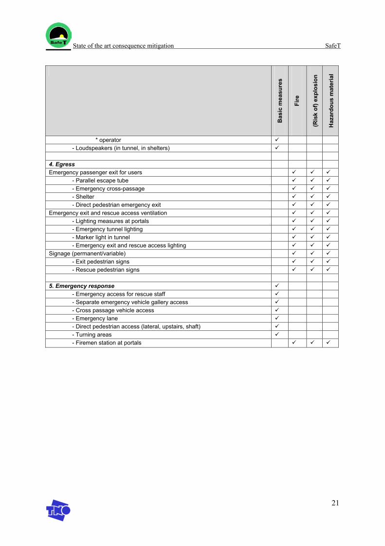
State of the art consequence mitigation SafeT
21
Bas
ic m
easu
res
Fire
(Ris
k of
) exp
losi
on
Haz
ardo
us m
ater
ial
* operator - Loudspeakers (in tunnel, in shelters) 4. Egress Emergency passenger exit for users - Parallel escape tube - Emergency cross-passage - Shelter - Direct pedestrian emergency exit Emergency exit and rescue access ventilation - Lighting measures at portals - Emergency tunnel lighting - Marker light in tunnel - Emergency exit and rescue access lighting Signage (permanent/variable) - Exit pedestrian signs - Rescue pedestrian signs 5. Emergency response - Emergency access for rescue staff - Separate emergency vehicle gallery access - Cross passage vehicle access - Emergency lane - Direct pedestrian access (lateral, upstairs, shaft) - Turning areas - Firemen station at portals
State of the art consequence mitigation SafeT
22
4.7 Discussion
The main reference documents for this overview are the proposal for the EU directive [1], and the “List of Guidelines” collected within FIT [2]. The technical measures, which are mentioned in the EU directive, can be mandatory, recommended or optional, depending on the tunnel class and the measure. In Work Package 3.3 of the FIT project, relevant guidelines concerning fire in road tunnels are collected and a comparison of selected guidelines is performed [2]. The draft report of this workpackage shows an interesting reference table with national guidelines of various countries and other reference documents [2]. Note that the FIT project is focussed on Fire accidents only, and therefore the reference table may have to be completed for SafeT. Also the comparisons of the guidelines that are performed by FIT may not comprise non-fire accidents, although the guidelines might include these accidents. It is recommended to study the FIT reference documents for non-fire aspects in the SafeT Workpackage 3.
For more information on the measures mentioned in table 4.1, the reader is referred to the proposal for the EU directive [1] and the FIT document [2]. The FIT document at this moment is available as a draft document for corresponding members only. FIT also developed a database on safety equipment in tunnels, which gives an overview of all kinds of safety equipment available. Perhaps groups of equipment or some special equipment tools can be included in guidelines.
In this state of the art overview for the SafeT project, only measures are shown which are already included in guidelines. Other reference documents to be studied in Workpackage 3 are for instance: − UPTUN- Task 5.1 - Comprehensive inventory of Tunnel Safety Features [5] − Overview of Dutch basic safety measures VRC [5] − Process analysis of self-rescue and emergency operation in tunnels [4]. − Best practice for safe operation and fire response management, FIT WP4 [3]
State of the art consequence mitigation SafeT
23
5. References
[1] Directive 2004/54/EC on minimum safety requirements for tunnels in the Trans-European Road Network, Brussels, 29 April 2004.
[2] Fire Safe Design road tunnels, WP3, 3.3. Road tunnels, FIT “Fire in Tunnels” European Thematic Network, 2nd draft, September 2003.
[3] FIT Network – WP4, “Best practice for safe operation and fire response management”, Draft for discussion, September 2003.
[4] Wiersma T., van der Torn P., “Procesanalyse zelfredding en hulpverlening in tunnels”, a co-production of NiVu and TNO, TNO-reportnr. R2003/236, 2003.
[5] VRC, 2003.
[6] Francesconi S., UPTUN- Task 5.1 - Comprehensive inventory of Tunnel Safety Features, 2004.
[7] www.tno.nl/instit/fel/gate
[8] www.tno.nl/instit/fel/gamma_ec
[9] www.virtualfires.org

SafeT
Work package 1 Task 1.4
D1.4 report
State of the art Post accident investigation and evaluation
Version: April 2005 Author: W.W.R. Koch
State of the art post accident investigation and evaluation SafeT
2
Table of contents
1. Introduction............................................................................................................................. 3
2. Types of investigations ........................................................................................................... 4
3. General accident investigation approach ................................................................................ 5
4. Consequences taken from the Mont Blanc and Tauern tunnel disasters................................. 8
5. Post accident investigation and evaluation according to the EU directive ........................... 10
6. Conclusion /discussion ......................................................................................................... 11
7. References............................................................................................................................. 12
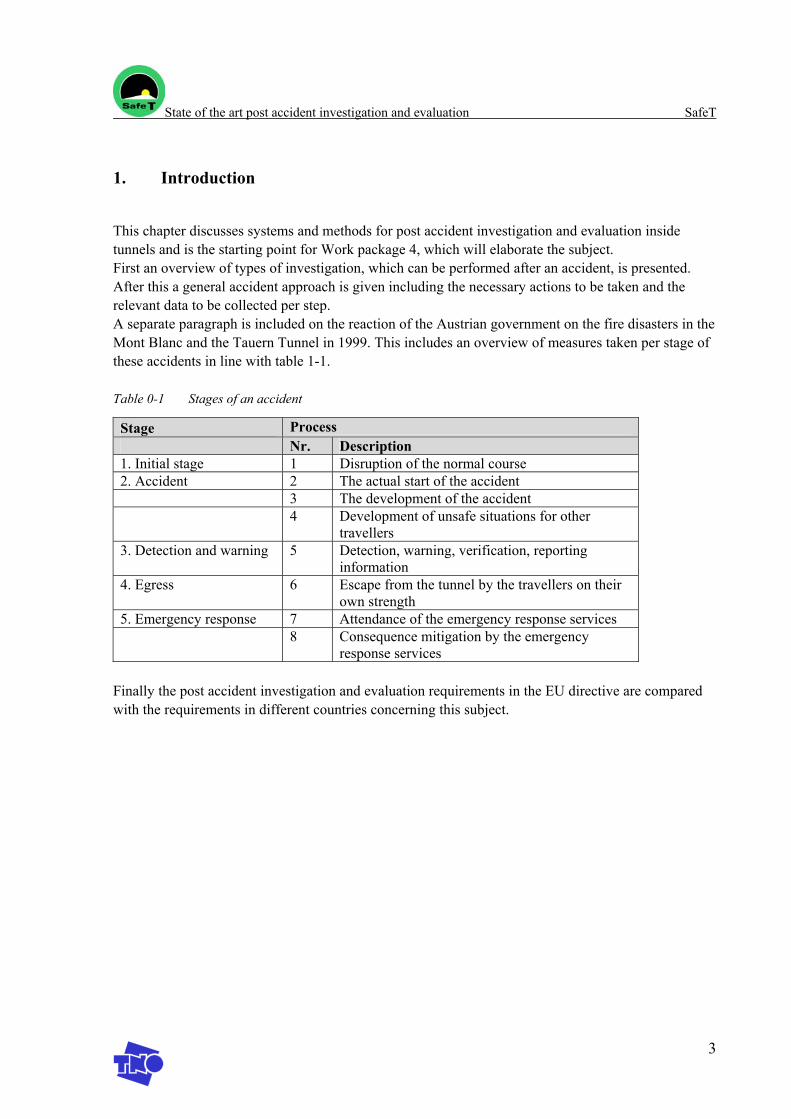
State of the art post accident investigation and evaluation SafeT
3
1. Introduction
This chapter discusses systems and methods for post accident investigation and evaluation inside tunnels and is the starting point for Work package 4, which will elaborate the subject. First an overview of types of investigation, which can be performed after an accident, is presented. After this a general accident approach is given including the necessary actions to be taken and the relevant data to be collected per step. A separate paragraph is included on the reaction of the Austrian government on the fire disasters in the Mont Blanc and the Tauern Tunnel in 1999. This includes an overview of measures taken per stage of these accidents in line with table 1-1.
Table 0-1 Stages of an accident
Stage Process Nr. Description 1. Initial stage 1 Disruption of the normal course 2. Accident 2 The actual start of the accident 3 The development of the accident 4 Development of unsafe situations for other
travellers 3. Detection and warning 5 Detection, warning, verification, reporting
information 4. Egress 6 Escape from the tunnel by the travellers on their
own strength 5. Emergency response 7 Attendance of the emergency response services 8 Consequence mitigation by the emergency
response services
Finally the post accident investigation and evaluation requirements in the EU directive are compared with the requirements in different countries concerning this subject.
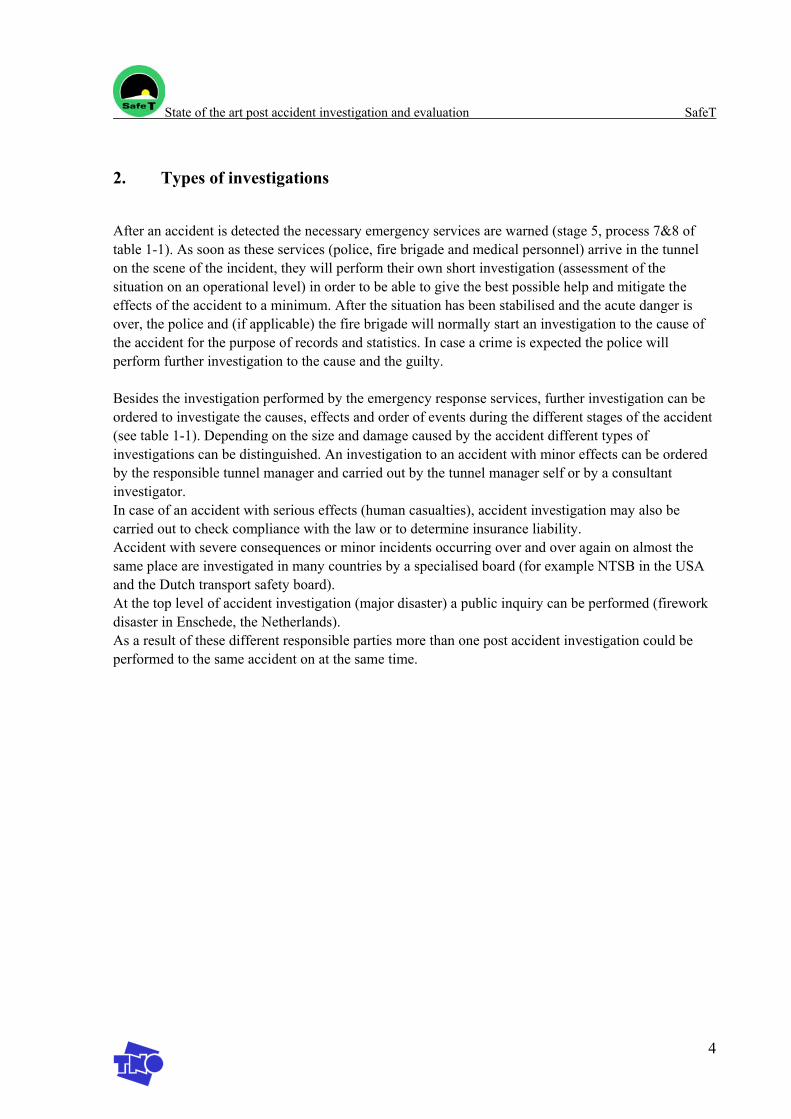
State of the art post accident investigation and evaluation SafeT
4
2. Types of investigations
After an accident is detected the necessary emergency services are warned (stage 5, process 7&8 of table 1-1). As soon as these services (police, fire brigade and medical personnel) arrive in the tunnel on the scene of the incident, they will perform their own short investigation (assessment of the situation on an operational level) in order to be able to give the best possible help and mitigate the effects of the accident to a minimum. After the situation has been stabilised and the acute danger is over, the police and (if applicable) the fire brigade will normally start an investigation to the cause of the accident for the purpose of records and statistics. In case a crime is expected the police will perform further investigation to the cause and the guilty.
Besides the investigation performed by the emergency response services, further investigation can be ordered to investigate the causes, effects and order of events during the different stages of the accident (see table 1-1). Depending on the size and damage caused by the accident different types of investigations can be distinguished. An investigation to an accident with minor effects can be ordered by the responsible tunnel manager and carried out by the tunnel manager self or by a consultant investigator. In case of an accident with serious effects (human casualties), accident investigation may also be carried out to check compliance with the law or to determine insurance liability. Accident with severe consequences or minor incidents occurring over and over again on almost the same place are investigated in many countries by a specialised board (for example NTSB in the USA and the Dutch transport safety board). At the top level of accident investigation (major disaster) a public inquiry can be performed (firework disaster in Enschede, the Netherlands). As a result of these different responsible parties more than one post accident investigation could be performed to the same accident on at the same time.
State of the art post accident investigation and evaluation SafeT
5
3. General accident investigation approach
Independent on the size of the accident, the amount of damage caused or the number of casualties, an investigation should start as soon as possible after the accident, while memories are still fresh and evidence is undisturbed. In particular, photographs, measurements and similar evidence should be taken on the site as soon as possible. Depending on the scope accident investigation may involve assessment of damage, interviewing survivors and (eye)witnesses, interviewing the tunnel-manager and/or -operators and the study of computer simulations. In general the next following steps can be distinguished [ref. 1]:
1. remit/scope 2. site visit 3. collection of background information 4. examination of damage 5. interviewing of (eye)witnesses and other people involved (tunnel-manager, -operators, etc.) 6. research and analyses 7. final report
1. Remit/scope The purpose and the scope of the investigation should be clearly defined from the beginning of the investigation and is dependent on the described stages in table 1-1. An investigation can be ordered to investigate the events related to one specific stage as presented in table 1-1, or an investigation could concern the cause of the accident and recommendations for measures to be taken to prevent repetition. Besides these possibilities, an investigation can be ordered to possible structural damage to the tunnel. Also see table 1-1.
2. Site visit The preliminary site visit should be made as soon as possible, because it should be as undisturbed as possible. The following actions should be taken:
• colour photographs of the site, including a record of the location and viewpoint of each photograph;
• sketches should be made, if appropriate; • ground plans can be used to draw the position of the vehicles and or damage areas; • the names should be obtained of the (eye)witnesses, the survivors of the accident and the
tunnels manager and the tunnel operators; • (eye)witnesses could be asked to write down their experiences whilst it is fresh, and even
better, before they have talked to other (eye)witnesses • recordings of the emergency calls to the operations room and from the operations room to the
called in emergency services (if available) • recordings of the CCVT camera or other camera systems (if available)
3. Background information The collection of background information includes the next following documents/actions:
• records of maintenance • records of previous incidents and accidents • assessment of the technical state (working order) of the electronic equipment inside the tunnel
State of the art post accident investigation and evaluation SafeT
6
• Risk analyses, which were performed before the accident occurred, may have considered incident scenario’s which are similar to the accident. The performed scenario calculations can be evaluated with the information on the real accident. It should be assessed whether the tunnel operators responded the way they where supposed to in relation to the applicable accident scenario, i.e. whether the lessons learnt from the risk analysis were applied in the actual accident.
• assessment of the level of knowledge and experience of the tunnel operators present at the time of the accident
• studying of the recordings of emergency calls and CCVT camera systems • studying the ventilation conditions and smoke movements, both the numerical simulations of
ventilation conditions and smoke movements for the applicable accident scenario and the eye-witness reports on smoke behaviour and ventilation efficiency.
4. Examination of damage Examination to the damage caused by technical experts, in order to determine whether the tunnel needs repairs.
• investigation after the size and the spread of damage done.
5. Interviewing Interviewing of the (eye)witnesses and other people involved, tunnel-manager, tunnel operators and people from the called in emergency services should be performed with care. Especially in cases with lots of casualties or sudden, short violent events the survivors observations tend to be unreliable or they might even suffer from shock.
6. Research & analyses The research and analyses phase concerns the analyses of all the gathered information and put up a working hypothesis. As part of this phase even a real life reconstruction of the accident can be performed on the site due to investigation in order to gain additional information on the accident.
After an accident investigation the cause of the accident is being classified in defined (sub)categories. In general there are two types of causes, first the hardware related (material factors) and the non-hardware related (human error). In order to classify an accident cause it is necessary to assess every accident in such a way the assessment provides the necessary information to be able to classify the accident cause in a specified (sub)category.
Material factors: • Technical failures • Design failures • Poor maintenance • Poor operation • Poor procedures
Human error: • Risk taking (people consciously taking risk) • Risk homoeostasis (people taking more risk, driving a car with ABS, EPS, air-bags, etc.) • Risk misjudgement
State of the art post accident investigation and evaluation SafeT
7
• Absentmindedness • Social factors (the antisocial factor) • Human health failure (heart attack, etc.) • Inadequate training
These categories are not only relevant as the primary accident cause but are pertinent to every stage of the accident (see Table 1-1) such as detection/warning, emergency response etc.
7. Reporting The final report holds the conclusions of the investigation and (should) give answers to the answers as formulated in the beginning of the investigation. In general the final report should give a clear answer to what happened, why it happened and give a suggestion how to prevent the accident from happening again (defence lines).
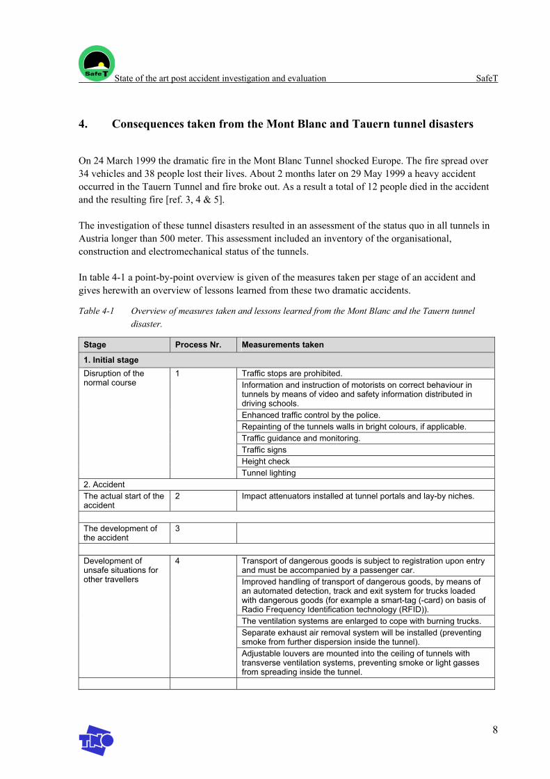
State of the art post accident investigation and evaluation SafeT
8
4. Consequences taken from the Mont Blanc and Tauern tunnel disasters
On 24 March 1999 the dramatic fire in the Mont Blanc Tunnel shocked Europe. The fire spread over 34 vehicles and 38 people lost their lives. About 2 months later on 29 May 1999 a heavy accident occurred in the Tauern Tunnel and fire broke out. As a result a total of 12 people died in the accident and the resulting fire [ref. 3, 4 & 5].
The investigation of these tunnel disasters resulted in an assessment of the status quo in all tunnels in Austria longer than 500 meter. This assessment included an inventory of the organisational, construction and electromechanical status of the tunnels.
In table 4-1 a point-by-point overview is given of the measures taken per stage of an accident and gives herewith an overview of lessons learned from these two dramatic accidents.
Table 4-1 Overview of measures taken and lessons learned from the Mont Blanc and the Tauern tunnel disaster.
Stage Process Nr. Measurements taken
1. Initial stage Traffic stops are prohibited. Information and instruction of motorists on correct behaviour in tunnels by means of video and safety information distributed in driving schools. Enhanced traffic control by the police. Repainting of the tunnels walls in bright colours, if applicable. Traffic guidance and monitoring. Traffic signs Height check
Disruption of the normal course
1
Tunnel lighting 2. Accident The actual start of the accident
2 Impact attenuators installed at tunnel portals and lay-by niches.
The development of the accident
3
Transport of dangerous goods is subject to registration upon entry and must be accompanied by a passenger car. Improved handling of transport of dangerous goods, by means of an automated detection, track and exit system for trucks loaded with dangerous goods (for example a smart-tag (-card) on basis of Radio Frequency Identification technology (RFID)). The ventilation systems are enlarged to cope with burning trucks. Separate exhaust air removal system will be installed (preventing smoke from further dispersion inside the tunnel).
Development of unsafe situations for other travellers
4
Adjustable louvers are mounted into the ceiling of tunnels with transverse ventilation systems, preventing smoke or light gasses from spreading inside the tunnel.
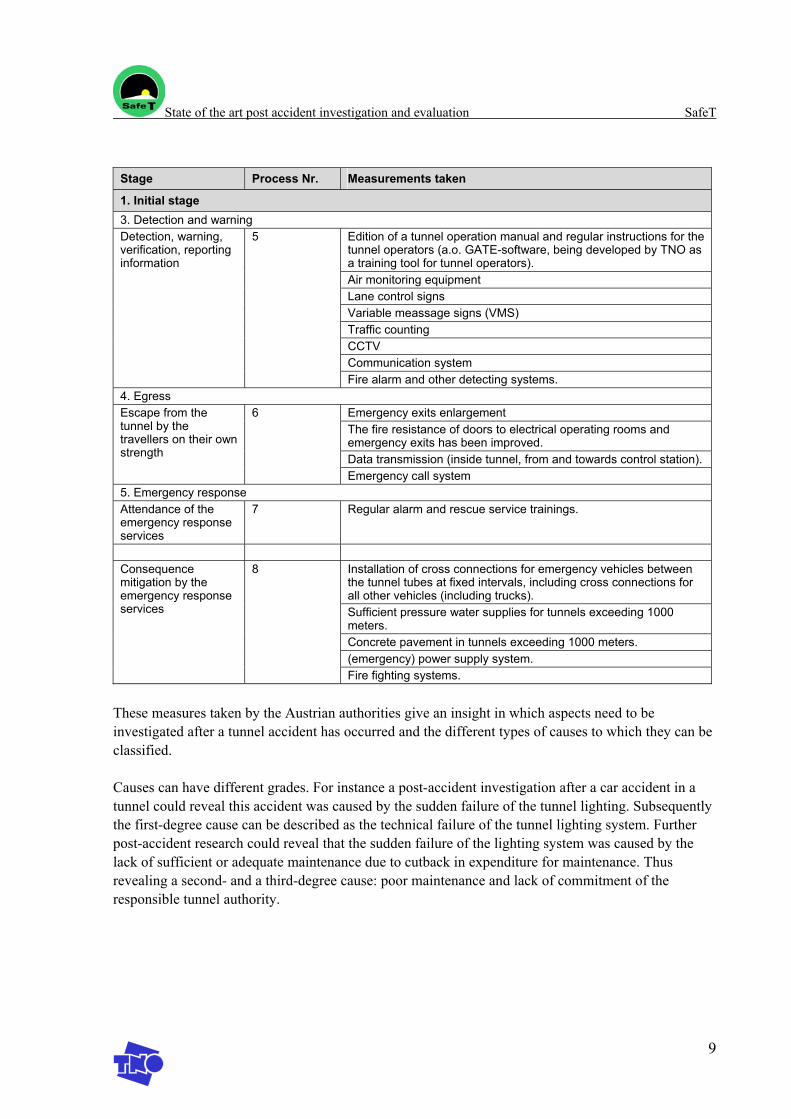
State of the art post accident investigation and evaluation SafeT
9
Stage Process Nr. Measurements taken
1. Initial stage 3. Detection and warning
Edition of a tunnel operation manual and regular instructions for the tunnel operators (a.o. GATE-software, being developed by TNO as a training tool for tunnel operators). Air monitoring equipment Lane control signs Variable meassage signs (VMS) Traffic counting CCTV Communication system
Detection, warning, verification, reporting information
5
Fire alarm and other detecting systems. 4. Egress
Emergency exits enlargement The fire resistance of doors to electrical operating rooms and emergency exits has been improved. Data transmission (inside tunnel, from and towards control station).
Escape from the tunnel by the travellers on their own strength
6
Emergency call system 5. Emergency response Attendance of the emergency response services
7 Regular alarm and rescue service trainings.
Installation of cross connections for emergency vehicles between the tunnel tubes at fixed intervals, including cross connections for all other vehicles (including trucks). Sufficient pressure water supplies for tunnels exceeding 1000 meters. Concrete pavement in tunnels exceeding 1000 meters. (emergency) power supply system.
Consequence mitigation by the emergency response services
8
Fire fighting systems.
These measures taken by the Austrian authorities give an insight in which aspects need to be investigated after a tunnel accident has occurred and the different types of causes to which they can be classified.
Causes can have different grades. For instance a post-accident investigation after a car accident in a tunnel could reveal this accident was caused by the sudden failure of the tunnel lighting. Subsequently the first-degree cause can be described as the technical failure of the tunnel lighting system. Further post-accident research could reveal that the sudden failure of the lighting system was caused by the lack of sufficient or adequate maintenance due to cutback in expenditure for maintenance. Thus revealing a second- and a third-degree cause: poor maintenance and lack of commitment of the responsible tunnel authority.
State of the art post accident investigation and evaluation SafeT
10
5. Post accident investigation and evaluation according to the EU directive
According to article 5 of the EU directive on minimum safety requirements for tunnels in the Trans-European Road Network Member States shall:
• Identify a public or private body responsible for the management of the tunnel (Tunnel Manager). The Administrative Authority itself may perform this function.
• For each tunnel located on the territory of two Member States, the two administrative authorities or the joint administrative authority shall recognise only one body in charge of the operation of the tunnel.
• Any significant incident or accident occurring in a tunnel shall be the subject of an incident report prepared by the Tunnel Manager. This report shall be forwarded to the Safety Officer referred to in Article 6, to the administrative authority and to the emergency services within a maximum period of one month.
• Where an investigation report is drawn up analysing the circumstances of the incident or accident referred to in paragraph 3 or the conclusions that can be drawn from it, the Tunnel Manager shall forward this report to the Safety Officer, the administrative authority and the emergency services no later than one month after he/she receives it himself/herself.
Besides this in article 6 of the EU directive on minimum safety requirements for tunnels in the Trans-European Road Network states that:
• For each tunnel, the Tunnel Manager shall, with the prior approval of the administrative authority, nominate one Safety Officer who shall coordinate all preventive and safeguards measures to ensure the safety of users and operational staff. The Safety Officer may be a member of the tunnel staff or the emergency services, shall be independent in all road tunnel safety issues and shall not be under instructions from an employer in respect of those issues. A Safety Officer may perform his/her tasks and functions at several tunnels in a region.
• Among others this Tunnel Manager shall take part in the evaluation of any significant incident or accident as referred to in Article 5(3) and (4).
The requirements of the Directive only apply to tunnels longer than 500 meter in the Trans-European Road Network. It is assumed that tunnel users can escape within 5 to 10 minutes in shorter tunnels.

State of the art post accident investigation and evaluation SafeT
11
6. Conclusion /discussion
Due to the fact that, the requirements for the subject considered in this literature search are very vague it is of the most importance that a standard minimal approach of post accident investigation and evaluation requirements is being lined up.
State of the art post accident investigation and evaluation SafeT
12
7. References
[1] Loss prevention in the Process Industries; Hazard Identification, Assessment and Control, Chapter 26 & 27, volume 2, second edition; Frank P. Lees; 1996; ISBN 0 7506 1547 8
[2] Directive 2004/54/EC on minimum safety requirements for tunnels in the Trans-European Road Network, Brussels, 29 April 2004.
[3] Lessons learnt by the sad tunnel incidents of the year 1999, Austria, R. Horman, Federal Ministry for Transport, Innovation & Technology; Proceedings of the Fourth International conference on Safety in Road and Rail Tunnels; 2-6 April 2001; Madrid, Spain; Organised an sponsored by the University of Dundee an Independent Technical Conferences Ltd.; edited by Alan E. Vardy; ISBN 1901808173
[4] The Mont Blanc Tunnel fire, what happened and what has been learned, France, D. Lacroix, Centre dÉtudes des Tunnels; Proceedings of the Fourth International conference on Safety in Road and Rail Tunnels; 2-6 April 2001; Madrid, Spain; Organised an sponsored by the University of Dundee an Independent Technical Conferences Ltd.; edited by Alan E. Vardy; ISBN 1901808173
[5] The Tauern Tunnel incident, what happened and what has to be learned, Austria, G. Eberl, OSAG; Proceedings of the Fourth International conference on Safety in Road and Rail Tunnels; 2-6 April 2001; Madrid, Spain; Organised an sponsored by the University of Dundee an Independent Technical Conferences Ltd.; edited by Alan E. Vardy; ISBN 1901808173