Embed Size (px)
Citation preview
Computers and Structures, Inc.Berkeley, California, USA
Version 8.0.0August 2004
SAFE
Integrated Analysis and Design of Slab Systems
Welcome to SAFE

Copyright Computers and Structures, Inc., 1978-2004.The CSI Logo is a registered trademark of Computers and Structures, Inc.
SAFE and CSiDETAILER are trademarks of Computers and Structures, Inc.“Watch & Learn” is a trademark of Computers and Structures, Inc.
Windows is a registered trademark of Microsoft Corporation.Adobe and Acrobat are registered trademarks of Adobe Systems Incorporated.
Copyright
The computer program SAFE and all associated documentation are proprietary andcopyrighted products. Worldwide rights of ownership rest with Computers andStructures, Inc. Unlicensed use of the program or reproduction of the documentation inany form, without prior written authorization from Computers and Structures, Inc., isexplicitly prohibited.
Further information and copies of this documentation may be obtained from:
Computers and Structures, Inc.1995 University Avenue
Berkeley, California 94704 USA
Phone: (510) 845-2177FAX: (510) 845-4096
e-mail: [email protected] (for general questions)e-mail: [email protected] (for technical support questions)
web: www.csiberkeley.com
DISCLAIMER
CONSIDERABLE TIME, EFFORT AND EXPENSE HAVE GONE INTO THEDEVELOPMENT AND DOCUMENTATION OF SAFE. THE PROGRAM HAS BEENTHOROUGHLY TESTED AND USED. IN USING THE PROGRAM, HOWEVER,THE USER ACCEPTS AND UNDERSTANDS THAT NO WARRANTY ISEXPRESSED OR IMPLIED BY THE DEVELOPERS OR THE DISTRIBUTORS ONTHE ACCURACY OR THE RELIABILITY OF THE PROGRAM.
THE USER MUST EXPLICITLY UNDERSTAND THE ASSUMPTIONS OF THEPROGRAM AND MUST INDEPENDENTLY VERIFY THE RESULTS.
i
Contents
Welcome to SAFE
1 Introduction
History and Advantages of SAFE 1-1
What SAFE Can Do! 1-2
An Integrated Approach 1-4
Modeling Features 1-4
Analysis Features 1-5
Design Features 1-5
Detailing Features 1-6
2 Getting Started
Installing SAFE 2-1
If You are Upgrading 2-1
About the Manuals 2-2
SAFE™SAFE™
Welcome to SAFE
ii
“Watch & Learn Movies" 2-2
Technical Support 2-3
Help Us Help You 2-3
Telephone and Facsimile Support 2-4
On-Line Support 2-4
3 The SAFE System
Overview of the Modeling Process 3-1
Physical Modeling Terminology 3-2
Structural Objects 3-3
Properties 3-4
Supports 3-4
Static Load Cases 3-5
Vertical Loads 3-5
Lateral Load Effects 3-6
Load Combinations 3-6
Design Procedures 3-6
More Information 3-7
4 SAFE Modeling Techniques
Overview of Slab Types 4-1
Two-Way Slabs 4-1
Flat Slabs 4-2
Ribbed Slabs 4-2
Waffle Slabs 4-3
Slabs with Discontinuities 4-3
Mat Foundations and Footings 4-3
Beam Types 4-3
Contents
iii
Models Exported from ETABS 4-4
More Information 4-4
5 SAFE Analysis Techniques
Overview of the Analysis Process 5-1
The Analysis Model 5-2
Linear Static Analysis 5-4
Nonlinear Analysis for Uplift 5-4
Nonlinear Analysis for Cracking 5-5
More Information 5-6
6 SAFE Design Techniques
Overview of the Design Process 6-1
Slab Flexural Design 6-2
Design Strips 6-2
Integration of Moments – Nodal 6-3
Integration of Moments – Wood-Armer 6-3
Slab Punching Shear Check 6-5
Beam Flexural and Shear Design 6-5
Output Display Options 6-6
More Information 6-6
7 CSiDETAILER Detailing Options
Overview of the Detailing Process 7-1
The Detailing Model 7-2
Drawings 7-2
Views 7-3
Tables and Schedules 7-4
More Information 7-4
History and Advantages of SAFE 1 - 1
Chapter 1
Introduction
SAFE is a sophisticated, yet easy to use, special purpose analysis and de-sign program developed specifically for concrete slab systems. SAFEcouples powerful object-based modeling tools with an intuitive graphicalinterface, allowing the user to quickly and efficiently model slabs ofregular or arbitrary geometry with openings, drop panels, ribs, edgebeams, and slip joints supported by columns, walls or soil. Design isseamlessly integrated with modeling and analysis, and provides compre-hensive reporting of the required reinforcing calculated by the programbased on the user’s choice of design code. And with the optionalCSiDETAILER program, detail drawings may be produced almost ef-fortlessly for the slabs and beams designed using SAFE.
History and Advantages of SAFESlab systems are a very special class of structures. They are characterizedby their simplicity in geometry and loading. They are typically horizontalplates supported vertically by beams, columns or walls. The loading ingeneral is comprised of vertical point, line and surface loads. Basemats
SAFE™SAFE™
Welcome to SAFE
1 - 2 What SAFE Can Do!
share the same characteristics as those of elevated slabs, with the excep-tion that basemats are supported on soil and loaded by columns andwalls.
Recognition of the unique characteristics of slab systems led to the origi-nal development of the SAFE program more that two decades ago. Earlyreleases of SAFE provided input, output and numerical solution tech-niques that took into consideration the modeling and analysis needs dis-tinctive to concrete slabs, providing a tool that offered significant savingsin time over general purpose finite element programs, and increased ac-curacy in comparison to equivalent frame methods.
As computers and computer interfaces evolved, so did SAFE, addingcomputationally complex analytical options such as cracked sectionanalysis, and powerful CAD-like drawing tools in a graphical and object-based interface. Although the current version looks radically differentfrom its predecessors of 20 years ago, its mission remains the same: toprovide the profession with the most efficient and comprehensive soft-ware for the analysis and design of slab systems. SAFE automates theanalysis and design process for the structural engineer, resulting in moresophisticated designs produced in fewer engineering labor hours.
Creation and modification of the slab model, execution of the analysis,checking and optimization of the design, and display of graphical resultsare all controlled through a single interface, and all aspects of the pro-gram are linked via a common database.
SAFE also serves up the latest developments in numerical techniques,solution algorithms, and design codes, including automatic finite elementmeshing of complex object configurations, very accurate plate bendingelements, stress-integration options that account for diagonal crackingbehavior, and the most recent American and International concrete de-sign codes.
What SAFE Can Do!SAFE offers the widest assortment of analysis and design tools availablefor the structural engineer working on concrete slabs. The following list
Chapter 1 - What SAFE Can Do!
What SAFE Can Do! 1- 3
represents just a portion of the types of systems and analyses SAFE canhandle easily:
Flat slabs
Flat slabs with perimeter beams
Basemats
Two-way slabs
Waffle slabs
Ribbed slabs
Rectangular or circular slabs
T-beam effects
Spread footings
Combined footings
Slabs subjected to any number of vertical load cases and combi-nations
Pattern live loads
Foundation uplift
Deflections calculated using cracked section analysis
Wall supports with out-of-plane bending stiffness
Slab reinforcing calculated based on user-defined design strips
Flexural and shear design of beams
Punching shear ratios
Design for twisting moments
Automatic transfer of geometry, loading and slab distortionsfrom ETABS
Welcome to SAFE
1 - 4 An Integrated Approach
And much, much more!
An Integrated ApproachSAFE is a completely integrated system. Embedded beneath the simple,intuitive user interface are very powerful numerical methods and designprocedures, all working from a single comprehensive database. This in-tegration means that only one model is created to analyze, design, and ifCSiDETAILER is present, detail the entire slab.
Everything is integrated into one versatile package with a single Win-dows-based graphical user interface. No external modules need to bemaintained, and data transfer between programs or modules is worryfree. The effects on one part of the slab from changes in another part areinstantaneous and automatic. The integrated modules include the follow-ing:
Drafting module for model generation.
Finite element based analysis module.
Output display and table generation module.
Concrete slab and beam design module.
Modeling FeaturesThe SAFE slab is idealized as an assemblage of area, line and point ob-jects. Area objects are used to model slabs, openings, soil supports, andsurface loads. Line objects model beams and wall supports and loads.Point objects are used for column supports and concentrated loads. Withrelatively simple modeling techniques, very complex slab systems maybe considered.
The geometry of the slab can be unsymmetrical, and the thickness of theslab may vary. Spacing of supports and loads may be completely arbi-trary and is not limited to the uniform spans typically associated withequivalent frame techniques.
Chapter 1 - Analysis Features
Analysis Features 1- 5
Construction or expansion joints may be modeled with or without sheartransfer by assigning bending and shear releases to the line object thatrepresents the joint.
Column and wall supports can provide both vertical stiffness and rota-tional stiffness to give a more accurate representation of the distributionof forces in the slab.
Analysis FeaturesStatic analyses for any number of user-specified vertical load cases arepossible, and those load cases may be combined with each other into anynumber of load combinations. Deflections calculated may include thosefor both elastic and cracked sections, and load cases may have long-termdeflection multipliers for the nonlinear cracked deflection analyses.
Basemats and foundations may be subjected to overturning moments thatcause uplift. The program offers a nonlinear solution that accounts for notension in the soil springs, as well as allowing soil moduli to varythroughout the model.
To account for orthotropic effects, a thickness may be specified in boththe X and Y directions for the slab properties. This can be useful tomodel slabs that have primarily one-way behavior, where cracking maybe predominant in one direction.
Output may be viewed graphically (including soil bearing pressuremaps), displayed in tabular output, sent to a printer, exported to a data-base file, exported to a CAD file, or saved in an ASCII file. Types ofoutput include slab and beam forces, reactions and displacements.
Design FeaturesFlexural design of reinforced concrete slabs and basemats and the flex-ural and shear design of beams can be performed based on a variety ofinternational design codes. Slab reinforcement location and layout iscontrolled using design strips. Design strip moments are obtained by in-tegrating the finite element stresses using an algorithm that always satis-
Welcome to SAFE
1 - 6 Detailing Features
fies equilibrium and accounts for the effects of twisting moments. Codebased punching shear checks are made around column supports and pointloads.
Detailing FeaturesDrawings showing the reinforcing detailing may be produced for bothslabs and beams when CSiDETAILER is used in conjunction withSAFE. The detailing may be based on the requirements of a selected de-sign code or on the preferences of the user. The user may prepare anynumber of drawings, and the drawings may contain plan views of rein-forcing layouts, sections, elevations, tables and schedules. Control overreinforcing bar sizes and minimum and maximum spacing along withcut-off (curtailment) lengths is provided through a detailing preferencescommand. Drawings may be printed directly from CSiDETAILER orexported to a DXF or DWG file for further refinement.
Installing SAFE 2 - 1
Chapter 2
Getting Started
SAFE is an easy to use, yet extremely powerful, special purpose programdeveloped expressly for concrete slab systems. This chapter will helpyou get started using the program.
Installing SAFEPlease follow the installation instructions provided in the separate in-stallation document included in your SAFE package, or ask your systemadministrator to install the program and give you access to it.
If You are UpgradingIf you are upgrading from a previous version of SAFE, you should beaware that the model is now defined in terms of objects, which are auto-matically and internally meshed into elements during analysis.
SAFE™SAFE™
Welcome to SAFE
2 - 2 About the Manuals
This significant change drastically improves the capability of the pro-gram, and we recommend that you read the remainder of this manual tofamiliarize yourself with this and the many other new features.
About the ManualsThis volume is designed to help you quickly become productive withSAFE. It provides this Welcome to SAFE manual, an Introductory User’sGuide, a Tutorial, a Design Manual, a User’s Manual for CSiDE-TAILER (an optional detailing program available with SAFE) and aVerification manual.
The next chapter of this Welcome to SAFE manual gives a synopsis ofthe terminology used in SAFE, while chapters 4 and 5 describe modelingand analysis techniques, respectively. Chapter 6 covers the design op-tions, while chapter 7 provides an overview of the detailing featuresavailable with CSiDETAILER, the optional program available withSAFE for generating detailed drawings of SAFE models. Additional in-formation about CSiDETAILER is available in the CSiDETAILERUser’s Manual.
The 14 chapters of the SAFE Introductory User’s Guide provide an in-troduction to the menu items used to create, analyze, and design a model.The SAFE Tutorial takes the user through the creation, analysis and de-sign of an example model. Further information about design in accor-dance with various codes is provided in the SAFE Design Manual. TheSAFE Verification manual provides comparisons of SAFE output withpublished results.
It is strongly recommended that you read this volume and view the tuto-rial movies available through CSI’s web site (see “Watch & LearnMovies”) before attempting to complete a project using SAFE.
Additional information can be found in the on-line Help facility availablewithin the SAFE graphical user interface, including Technical Notes inAdobe Acrobat .PDF format that describe various design techniques.
Chapter 2 - “Watch & Learn( Movies”
“Watch & Learn( Movies” 2- 3
“Watch & Learn Movies”One of the best resources available for learning about the SAFE programis the “Watch & Learn Movies” series, which may be accessed on theSAFE CD or through the CSI web site at http://www.csiberkeley.com.Those movies contain a wealth of information for both the first-time userand the experienced expert, covering a wide range of topics from basicoperation to complex modeling. The movies vary in length from 3 to 15minutes and include narration.
Technical SupportFree technical support is available from Computers and Structures, Inc.(CSI) via telephone, facsimile, and e-mail for 90 days after the softwarehas been purchased. After 90 days, technical support is available in ac-cordance with the terms of the Software Maintenance Agreement, whichyou may purchase from CSI or your dealer. Please contact CSI or yourdealer to inquire about a Software Maintenance Agreement.
If you have questions regarding use of the software, we suggest the fol-lowing:
Consult this documentation and other printed information in-cluded with your product.
Check the on-line Help facility in the program.
Review the “Watch and Learn Movies” provided on theSAFE CD or at CSI’s web site at http://www.csiberkeley.com.
If you cannot find an answer, then contact us as described in the sec-tions that follow.
Help Us to Help YouWhenever you contact us with a technical support question, please pro-vide us with the following information to help us help you:
Welcome to SAFE
2 - 4 Telephone and Facsimile Support
The version number that you are using. This can be obtainedfrom inside the program using the Help menu > About SAFEcommand.
A description of your model, including a picture, if possible.
A description of what happened and what you were doing whenthe problem occurred.
The exact wording of any error messages that appeared on yourscreen.
A description of how you tried to solve the problem.
The computer configuration (make and model, processor, oper-ating system, hard disk size, and RAM size).
Your name, your company’s name, and how we may contactyou.
Telephone and Facsimile SupportStandard telephone and fax support is available in the United States,from CSI support engineers, via a toll call between 8:30 A.M. and 5:00P.M., Pacific time, Monday through Friday, excluding U.S. holidays.
You may:
Contact CSI’s office via phone at (510) 845-2177, or
Send a fax with questions and information about your model(including a picture, if possible) to CSI at (510) 845-4096.
When you call, please be at your computer and have the program manu-als at hand.
Online SupportOnline support is available by:
Chapter 2 - Online Support
Online Support 2- 5
Sending an e-mail and your model file to [email protected]
Visiting CSI’s web site at http://www.csiberkeley.com to readabout frequently asked questions.
If you send us e-mail, be sure to include all of the information requestedin the previous “Help Us to Help You” section.
Overview of the Modeling Process 3 - 1
Chapter 3
The SAFE System
SAFE analyzes and designs a concrete slab system for the model createdusing the graphical user interface. The key to successfully implementingSAFE is to understand the unique and powerful approach the programtakes in modeling slabs. This chapter will provide an overview of someof the special features and their associated terminology.
Overview of the Modeling ProcessA model developed using this program is different from models pro-duced in many other structural analysis programs for two main reasons:
The program is optimized for modeling slab systems because themodeling procedures and design capabilities are all tailored toconcrete slabs and beams.
The program’s models are object-based and consist of point, lineand area objects to which assignments are made to define struc-tural members, such as slabs, beams, columns, and supports, aswell as to define loads.
SAFE™SAFE™
Welcome to SAFE
3 - 2 Physical Modeling Terminology
In its simplest form, developing a model requires three basic steps:
Define slab and beam properties (sections and materials) andsupports using the Define menu options.
Draw a series of point, line and area objects that represent yourslab using the various drawing tools available within the graphi-cal interface.
Assign structural properties, supports and loads to objects usingthe Assign menu options. Note that the assignment of structuralproperties and supports may be completed concurrently with thedrawing of the object using the Properties of Object form thatappears when a Draw command is used.
When the model is complete, the analysis may be run. At that time, theprogram automatically converts the object-based model into an element-based model that is used for the analysis—this is known as the analysismodel. The analysis model consists of joints, frame elements, plate ele-ments and springs in contrast to the point, line and area objects in theuser-defined object-based model. The conversion to the analysis model isinternal to the program and essentially transparent to the user. In addi-tion, object meshing is performed automatically, with control over themaximum mesh dimension available on the Analysis menu.
Physical Modeling TerminologyIn SAFE, we often refer to objects, members, and elements. Objects rep-resent the physical structural members in the model. Elements, on theother hand, refer to the finite elements used internally by the program togenerate the stiffness matrices. In many cases, objects and physicalmembers will have a one-to-one correspondence, and it is these objectsthat the user “draws” in the SAFE interface. Objects are intended to bean accurate representation of the physical members; users typically neednot concern themselves with the meshing of these objects into the ele-ments required for the mathematical, or analysis, model. For example, asingle area object can model an entire slab, regardless of the number ofspans and variety of loadings. With SAFE, both model creation, as wellas the reporting of results, is achieved at the object level.
Chapter 3 - Structural Objects
Structural Objects 3- 3
This differs from a traditional analysis program, where the user is re-quired to define a sub-assemblage of finite elements that comprise thelarger physical members. In SAFE, the objects, or physical membersdrawn by the user, are typically meshed internally into the greater num-ber of finite elements needed for the analysis model, without user input.Because the user is working only with the physical member-based ob-jects, less time is needed both to create the model and to interpret the re-sults.
The concept of objects in a structural model may be new to you. It is ex-tremely important that you grasp this concept because it is the basis forcreating a model in SAFE. After you understand the concept and haveworked with it for a while, you should recognize the simplicity of physi-cal object-based modeling, the ease with which you can create modelsusing objects, and the power of the concept when editing and creatingcomplex models.
Structural ObjectsAs stated previously, SAFE uses objects to represent physical structuralmembers. When creating a model, the user starts by drawing the geome-try of the object, and then assigning properties and loads to completelydefine the slab structure.
The following object types are available, listed in order of geometricaldimension:
Point objects are automatically created at the corners or ends ofall other types of objects and also can be added anywhere in themodel. Point objects are used to model column supports, pointloads and point displacements.
Line objects are used to model beams, wall supports and lineloads.
Area objects are used to model slabs, drop panels, column ge-ometry, openings, soil supports and surface loads.
Welcome to SAFE
3 - 4 Properties
As a general rule, the geometry of the object should correspond to that ofthe physical member. This simplifies the visualization of the model andreduces the chances of input error.
PropertiesProperties are “assigned” to each object to define the structural behaviorof that object in the model. Some properties, such as slab and beamproperties that contain both material and section definitions, are namedentities that must be specified before assigning them to objects. If aproperty is assigned to an object, for example a beam property to a lineobject, any changes to the definition of the property will automaticallyapply to the object. A named property has no effect on the model unlessit is assigned to an object.
Other properties, such as releases or point restraints, are assigned directlyto objects. Those properties can only be changed by making another as-signment of that same property to the object; they are not named entitiesand they do not exist independent of the objects.
SupportsSupports may be assigned to point, line and area objects, and similar toproperties, they are named entities that must be specified before beingassigned. The three types of supports are as follows:
Column supports for assignment to point objects.
Wall supports for assignment to line objects.
Soil supports for assignment to area objects.
On the basis of the object type and the associated support properties, theprogram generates spring elements at each mesh location.
Chapter 3 - Static Load Cases
Static Load Cases 3- 5
Static Load CasesStatic loads represent actions upon the structure, and include force, pres-sure, and support displacement. A spatial distribution of loads upon thestructure is called a load case.
Any number of static load cases can be defined. Typically you wouldhave separate load cases for dead load, live load, pattern live load, staticearthquake load, wind load, snow load, and so on. Loads that need tovary independently, either for design purposes or because of how theyare applied to the slab, should be defined as separate load cases.
After defining a static load case name, you must assign specific load val-ues to the objects as part of the load case. The load values you assign toan object specify the type of load (e.g., force or displacement), its magni-tude, and direction. Different loads can be assigned to different objects aspart of a single load case and each object can be subjected to multipleload cases.
Vertical LoadsVertical loads may be applied to point, line and area objects. Verticalloads are typically input in the down, or -Z direction. Point objects canaccept concentrated forces or moments. Line objects may have uniformdistributed forces, moments or torsions. Uniform (surface) loads can beapplied to area objects. Vertical load cases may also include element selfweight.
Some typical vertical load cases used for slabs might include:
Dead load
Superimposed dead load
Live load
Pattern live load
Snow load
Welcome to SAFE
3 - 6 Lateral Load Effects
Lateral Load EffectsAlthough SAFE limits the deformations in the slab to out-of-plane be-havior and thus is not appropriate for diaphragm studies, other effectscaused by lateral loads may be considered using load and displacementassignments. For suspended slabs, specified slab deformations (rotationsand displacements) may be assigned to columns and walls to account forframe behavior under lateral loads. If the user is using ETABS to per-form a 3-D building analysis, ETABS allows for the direct export offloor loads and distortions to SAFE for further analysis and design.
Overturning on basemats or foundations resulting from lateral loads maybe modeled by applying moments or moment couples to walls and mo-ments and vertical loads to columns. SAFE provides a nonlinear iterativesolution to model no-tension (uplift) behavior in the soil springs.
Load CombinationsLoad combinations combine the results of previously defined load casesin an additive manner. SAFE allows combinations to be named. When aload combination is defined, it applies to the results for every object inthe model.
Design is always based on load combinations, not directly on load cases.A combination that contains a single load case can be created. Each de-sign algorithm creates its own default combinations, which can be sup-plemented with user-defined design combinations if needed.
Design ProceduresSAFE has two integrated design postprocessors: Concrete Slab Designand Concrete Beam Design. The concrete slab design procedure is appli-cable to area objects with slab property definitions, and the beam designprocedure is available for line objects that have previously been assignedbeam properties.
Design can be affected by the following:
Chapter 3 - More Information
More Information 3- 7
The design code, e.g., ACI 318-95, EUROCODE 2-1991, orBS8110 – 85 R 1989, among others.
The design method and strength reduction factors.
Load combinations for which the design should be checked.
X- and Y- design strips for the slabs, which determine the layoutof the calculated reinforcing. The average moments across thestrips are used to calculate the required flexural reinforcing.
More InformationThis chapter presented just a brief overview of some of the basic compo-nents of the SAFE model. Additional information can be found in the on-line Help facility available within the SAFE graphical user interface aswell as in the other chapters of this manual and the other books in thisvolume.
Overview of Slab Types 4 - 1
Chapter 4
SAFE Modeling Techniques
SAFE offers an extensive and diverse range of tools to model a widerange of slab systems. This chapter will illustrate a few of the techniquesto make modeling easy and quick using SAFE.
Overview of Slab TypesSAFE can be used to model almost any type of elevated slab or basemat/foundation system, including two-way slabs, flat slabs, ribbed slabs, andwaffle slabs.
Two-Way SlabsTwo-way slabs (flat plates and flat slabs) are probably the most commonconcrete slab systems, and are easily modeled using SAFE. BecauseSAFE is finite element based, when a two-way slab of arbitrary shape isdrawn, the program automatically meshes the area objects into isotropicor orthotropic thin plate bending elements. Those elements are three- tofour-node elements, with one vertical and two rotational degrees of free-
SAFE™SAFE™
Welcome to SAFE
4 - 2 Overview of Slab Types
dom at each node, which capture out-of-plane bending behavior. Thus,two-way slab action is automatically accounted for in the SAFE model,and unlike equivalent frame techniques, requires no additional assump-tions or calculations.
Flat SlabsFlat slabs are typically two-way slabs with drop panels in the column re-gions to increase the shear capacity of the slab. It is usually advisable tomodel the geometric plan dimensions of the drops and columns with areaobjects so that the slabs will have the correct span lengths, rememberingthat moment varies directly with the square of the span length.
Both drop panels and columns are easily modeled in SAFE by drawingarea objects and then assigning thickened slab properties with either adrop or column type identifier.
Ribbed SlabsRibbed slabs are slabs stiffened by ribs running in one predominant di-rection. Modeling this type of system in a conventional finite elementprogram can be extremely difficult and time consuming because of themeshing effort involved. However, with SAFE’s object oriented ap-proach and automated meshing capability, ribbed slabs can be modeledsimply by drawing the area object representing the slab, and assigning a“Ribbed” slab property type.
Ribs are defined by specifying their depth, their widths at the top andbottom, and their spacing. The program then calculates equivalent slabproperties, such as the moment of inertias and self weight, using the slaband rib definitions. This calculation takes into account the T-beam be-havior occurring when the slab and ribs work together, with the slabacting as a flange.
Although an equivalent slab property is used internally when performingthe analysis, the actual geometry of the slab and ribs is used for designand detailing purposes.
Chapter 4 - Slabs with Discontinuities
Slabs with Discontinuities 4- 3
Waffle SlabsWaffle slabs are similar to ribbed slabs, but instead of ribs in only one di-rection, the waffle slab joists are laid out in an intersecting orthogonalgrid. In addition, waffle slabs also typically use drop panels at the col-umn locations. Similar to ribbed slabs, joists in a waffle slab are definedby specifying their depth, their widths at the top and bottom, and theirspacing. Again, the program uses equivalent slab properties for theanalysis, accounting for T-beam behavior, while maintaining the slab andjoist geometries for design and detailing.
Slabs with DiscontinuitiesThe slab release capability of SAFE allows for the convenient modelingof discontinuities. Releases allow jumps in moment or shear across aspecific line of discontinuity. Releases are assigned to line objects.
Mat Foundations and FootingsSimilar to elevated slabs, basemats and footings can be drawn using areaobjects to which slab properties are assigned. In addition to the thin plateelement described for elevated slabs, SAFE also offers a thick plate ele-ment that incorporates shear deformation for slabs that have a largedepth-to-span ratio, as is often the case with foundations. Stiffening wallscan be incorporated, along with the correct spatial distribution of loadsfrom columns (punching shear).
Soil springs can be added quickly to the model. Any number of soil sup-port properties may be defined, so that the subgrade modulus can varythroughout the foundation. An optional iterative process to model no-tension (uplift) in the soil springs is also available.
Beam TypesThe majority of beams in concrete construction are formed in a rectan-gular shape. However, beams can come in other shapes, and SAFE, inaddition to providing the rectangular beam, offers a number of other
Welcome to SAFE
4 - 4 Models Exported from ETABS
geometric beam options, including T Beams, Inverted T Beams, LBeams, and a General Beam option that can be used to model beams notreflected by one of the other categories.
Models Exported from ETABSOften times a concrete floor system defined in ETABS will require fur-ther refinement during analysis (e.g., deflections based on cracked sec-tions), as well as design and detailing. This can be accomplished easilyusing the link provided between ETABS and SAFE/CSiDETAILER.ETABS allows for the export of any story level as a SAFE.f2k text file.
In addition to the geometry and property assignments of the objects,ETABS provides three additional export options:
Export floor loads only.
Export floor loads and loads from above.
Export floor loads plus column and wall distortions.
The last export option allows SAFE to include the effects of lateral loads.
More InformationThis chapter was intended to illustrate just some of the many techniquesSAFE provides for the efficient modeling of slab systems. Much moreinformation may be found in the on-line Help and in the “Watch & LearnMovies” series.
Overview of the Analysis Process 5 - 1
Chapter 5
SAFE Analysis Techniques
This chapter provides an overview of some of the analysis techniquesavailable within SAFE. The types of analyses described are linear staticanalysis, nonlinear analysis for uplift, and nonlinear analysis for crack-ing.
In a given analysis, a nonlinear uplift analysis or a nonlinear crackinganalysis can be specified, but not both in a single run. A linear elasticanalysis must always precede a nonlinear cracking analysis.
Overview of the Analysis ProcessAt the time of analysis, SAFE converts the object-based model createdby the user into a finite element model, called the analysis model. The fi-nite element mesh used in the analysis is a rectangular mesh based on amaximum acceptable element size. However, extra mesh lines are intro-duced at all locations of objects, object boundaries, and gridlines. Addi-tional mesh lines can be introduced at specified locations by adding
SAFE™SAFE™
Welcome to SAFE
5 - 2 The Analysis Model
gridlines. SAFE also has options to modify meshing by setting themaximum mesh dimension.
After the mesh has been generated, SAFE automatically creates slabelements by subdividing all the area objects that have been assigned slabproperties. SAFE also creates beam elements by subdividing all the lineobjects that have been assigned beam properties.
Support properties are lumped into discrete springs and are assigned tofinite element mesh points. Support properties of all point objects are as-signed directly to the corresponding finite element mesh point. Supportproperties for all line objects are discretized and applied to all of themesh points that exist on the line based on the tributary length associatedwith the mesh point. Similarly, support properties of all area objects arediscretized and applied to all the mesh points that exist within the areaand on the boundaries of the area, based on the tributary area associatedwith the mesh point.
Point loads of all point objects are assigned directly to the correspondingfinite element mesh point. Line loads of all line objects are discretizedand applied to all the mesh points that exist on the line based on thetributary length associated with the mesh point. Similarly, surface loadsof all area objects are discretized and applied to all the mesh points thatexist within the area and on the boundaries of the area based on thetributary area associated with the mesh point.
All of the internal meshing and assigning performed by the program doesnot alter the number or size of the objects, which allows revisions andmodifications to be executed at the object level.
The Analysis ModelThe analysis model consists of slab, beam and support elements. Eachslab element is an isotropic or orthotropic, thin or thick plate bendingelement. The essential features of the plate elements are as follows:
Each of the element nodes has one vertical and two rotationaldegrees of freedom.
Chapter 5 - The Analysis Model
The Analysis Model 5- 3
The material properties and thickness within each element areconstant.
Optionally, to model orthotropic effects, it is possible to specifythree different effective thicknesses: X-direction bending, Y-direction bending, and twisting.
The slab system must exist in the XY plane.
In-plane action is not allowed in the XY plane; therefore, mem-brane stresses in the plane of the slab do not exist.
The calculation of the self weight of the slab element is based onthe design thickness, the XY dimensions of the element, and theunit weight of the element.
Slab element moments and shears are calculated at the meshpoints of the element.
The beam element in SAFE is based on linear elastic beam theory andcan have properties based on the dimensions of the specified cross sec-tion or on the input cross-sectional properties, such as the moment of in-ertia. Other characteristics of beam elements are as follows:
Beam elements are prismatic.
In-plane action is not allowed in the XY plane; therefore, beamaxial forces do not exist.
The calculation of the self-weight of the beam is based on the ac-tual area for rectangular or general sections and the stem area forT-, inverted T-, and L-sections, length between mesh points, andunit weight of the beam.
The beam moments, shears, and torques are calculated at the twoends of the element, that is, at each mesh point.
If any participation of the slab is to be included in the bending ofany beam, specify the beam as a T-beam or an L-beam.
Column supports are modeled as linear elastic spring elements at thepoint object location. For wall and soil supports, the program generates
Welcome to SAFE
5 - 4 Linear Static Analysis
equivalent mesh point linear elastic springs. Optionally, you can activatean iterative process to model no-tension conditions in the soil supports.The fundamental features of the support elements are as follows:
Column supports have three degrees of freedom: one vertical andtwo rotational.
Wall supports have one vertical and one rotational (out-of-plane)degree of freedom.
Soil supports have a single vertical degree of freedom.
The support elements are weightless.
The support reaction values are produced at every supportedmesh point.
Linear Static AnalysisA linear static analysis is automatically performed for each static loadcase that is defined. The user may specify any number of load cases foranalysis. The results of different static load cases can be combined witheach other using load combinations. A linear static analysis is the defaultanalysis in SAFE.
Nonlinear Analysis for UpliftSAFE has an option to request nonlinear analysis to consider soil sup-ports as providing compressive support only. This option requires thatload combinations be defined before an analysis is requested. Nonlinearanalysis is performed only for load combinations and not for individualload cases. SAFE applies an iterative procedure using the original stiff-ness and corrective load vectors to obtain the no-tension results.
This procedure converges asymptotically. The iterations for load combi-nations cease when a user-specified number of iterations has beenreached or when the maximum tension pressure as a ratio of the maxi-mum compressive pressure is below a user-specified convergence toler-
Chapter 5 - Nonlinear Analysis for Cracking
Nonlinear Analysis for Cracking 5- 5
ance. When this option is activated, all program results for loading com-binations are for this nonlinear analysis.
Nonlinear Analysis for CrackingIn the design of slabs, it is generally recognized that the distribution ofmoments obtained from an elastic analysis is appropriate for design pur-poses. However, an elastic analysis may significantly underestimate thetrue deflections.
The estimation of true deflections is a complex task. Some guidelines areavailable in design codes, such as the ACI 318-95 Section 9.5. Forbeams, that code recommends calculation of effective stiffness to obtainthe cracked deflections and then application of modification factors toaccount for long-term deflections. SAFE uses the recommendation con-cerning effective stiffness for slabs and beams of floor systems to obtaincracked deflections. The procedure is as follows:
Perform elastic (uncracked) analysis.
Design the slab reinforcement.
Calculate cracking moment and cracked moment of inertia foreach element for each direction of moment and for top and bot-tom reinforcement.
Calculate service level moments as the summation of dead andlive moments.
Calculate the ratio of effective stiffness to gross-section stiffnessfor both X and Y directions for the slab elements and for thebeam elements.
Reanalyze the structure using the effective stiffness calculatedfor each element.
The reanalysis results are saved for only the displacements and are re-ported as cracked deflections. All other results are for the original elastic(uncracked) analysis. The cracked deflection results should be treated as
Welcome to SAFE
5 - 6 More Information
estimates and need to be modified using appropriate factors to representlong-term deflections.
More InformationThis chapter provides a general introduction to the primary analyticaltechniques SAFE offers for linear and nonlinear analysis of slabs. Muchmore information may be found in the on-line Help and in the “Watch &Learn Movies” series.
Overview of the Design Process 6 - 1
Chapter 6
SAFE Design Techniques
This chapter provides an overview of some of the design techniquesavailable within SAFE. The types of design described are slab flexuraldesign, slab punching shear check, and beam flexural and shear design.Please refer to the SAFE Design Manual for information about code spe-cific design.
Overview of the Design ProcessAfter the analysis has been completed, design may begin. Design loadsare generated from built-in default load combinations for the specifiedcode (users may also specify their own load combinations, if needed).Using those loads, the program designs both slabs and beams, and re-ports the calculated reinforcing on-screen.
For slabs, SAFE uses a simple layering system to separate the designfrom the analysis model. The layers define the design strips that SAFEuses to calculate the flexural slab reinforcing in accordance with a user-
SAFE™SAFE™
Welcome to SAFE
6 - 2 Slab Flexural Design
selected code. SAFE also designs the flexural and shear reinforcing ofany line object that has been assigned a beam type.
Slab Flexural DesignSimilar to conventional design, the flexural design of slabs in SAFE in-volves defining sets of strips in two mutually perpendicular directions,integrating strip moments and shears (on the basis of nodal or Wood-Armer techniques), and then designing the strips in accordance with auser-selected code. Code specific design is described in the SAFE De-sign Manual.
The design of the slab reinforcement for a particular strip is completed ateach transverse mesh line location along the length of the strip. Momentsare integrated across elements of like property type to arrive at designmoments. Controlling reinforcement is computed for each set of ele-ments with the same property type, and then all of the reinforcements aresummed to give the total reinforcing for the strip. The maximum top andbottom strip reinforcements for each side of a particular mesh line areobtained along with the corresponding controlling load combinations.
As an option, minimum reinforcement requirements may be included inaccordance with a user-selected code. SAFE’s slab design is intended tosatisfy strength requirements only.
Design StripsSAFE provides three layers for analysis and design: the Structural Layer,the X-Direction Strip Layer, and the Y-Direction Strip Layer. TheStructural Layer is used to define the structural geometry, supports andloads—it is the analysis layer. The X- and Y-Direction Strip Layers areused for defining the design strips. The strips are, in fact, rectangulararea objects, and each object is a design strip in the direction corre-sponding to the layer.
The strips can only run parallel to the X- or Y-axis of the grid system andmust be perpendicular; skewed strips are not currently possible. The ex-tent of the design strips is defined by the edges of the area objects defin-
Chapter 6 - Slab Flexural Design
Slab Flexural Design 6- 3
ing the slab, and strips can overlap if needed. The locations of the designstrips are usually governed by the locations of the supports. If the userdoes not define design strips and a design is requested, the program willprovide default design strips on the basis of grid line locations.
Integration of Moments – NodalThe total integrated cross-sectional moments and shears along the lengthof a design strip are obtained for design and display purposes. If nodalintegration has been specified as the preference, the moments are inte-grated as follows:
For a particular load combination or load case for each finiteelement within the design strip, the program calculates the nodalpoint reactive moments. Those moments are obtained by multi-plying the slab element stiffness matrices by the element nodaldisplacement vectors.
The nodal point moments for each set of slab elements with thesame property type are then added to get a single positive and asingle negative design moment for each set of element types, onemesh line at a time. If all of the elements across the strip havethe same property assignment (same thickness and material),there would be only one positive and one negative moment.
The positive and negative moments are totaled separately.
This process is repeated for both sides of each mesh line.
The moments calculated using the nodal approach will always be incomplete static equilibrium with the applied loads, irrespective of the re-finement of the finite element mesh. This approach is best suited for useon a model where the mesh is poorly developed. However, the automatedmeshing procedure provided by SAFE makes the development of a poormesh extremely unlikely, so generally, it is advisable to use the Wood-Armer integration scheme described in the next section.
Welcome to SAFE
6 - 4 Slab Flexural Design
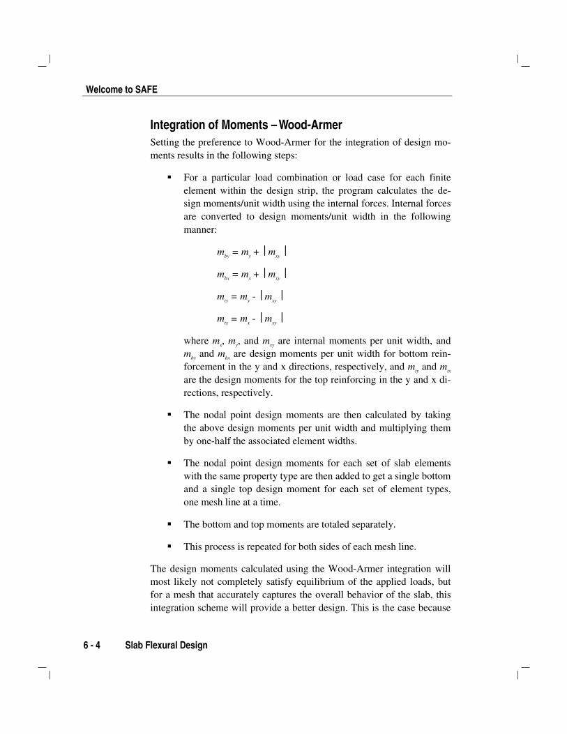
Integration of Moments – Wood-ArmerSetting the preference to Wood-Armer for the integration of design mo-ments results in the following steps:
For a particular load combination or load case for each finiteelement within the design strip, the program calculates the de-sign moments/unit width using the internal forces. Internal forcesare converted to design moments/unit width in the followingmanner:
mby = my + mxy
mbx = mx + mxy
mty = my - mxy
mtx = mx - mxy
where mx, my, and mxy are internal moments per unit width, andmby and mbx are design moments per unit width for bottom rein-forcement in the y and x directions, respectively, and mty and mtx
are the design moments for the top reinforcing in the y and x di-rections, respectively.
The nodal point design moments are then calculated by takingthe above design moments per unit width and multiplying themby one-half the associated element widths.
The nodal point design moments for each set of slab elementswith the same property type are then added to get a single bottomand a single top design moment for each set of element types,one mesh line at a time.
The bottom and top moments are totaled separately.
This process is repeated for both sides of each mesh line.
The design moments calculated using the Wood-Armer integration willmost likely not completely satisfy equilibrium of the applied loads, butfor a mesh that accurately captures the overall behavior of the slab, thisintegration scheme will provide a better design. This is the case because

Chapter 6 - Slab Punching Shear Check
Slab Punching Shear Check 6- 5
the Wood-Armer integration scheme more effectively calculates designmoments when cracking occurs diagonally to the design strip directions.
Slab Punching Shear CheckThe distribution of stresses close to concentrated loads or reaction pointsin reinforced concrete slabs is quite complex. Punching shear is one par-ticular failure mode recognized by design codes for which an elasticplate bending analysis may not provide adequate stress distribution. Mostcodes use empirical methods based on experimental verification to checkagainst punching shear failures. SAFE automates this check for the morecommon geometries. The SAFE procedure for the punching shear checkfor each column for each design load combination is as follows (de-scribed with reference to ACI 318-95):
Locate the critical section around the column or point load. Theprogram reports whether it assumed the column to be an interior,edge, or corner column. This determination is based on mini-mum area of the critical section. The program does not currentlyaccount for changes in slab depth, presence of openings, beamsor walls, and other discontinuities.
Calculate the reactive force and moments at the column for theload combination.
Calculate the distribution of shear stress around the critical sec-tion.
Obtain the shear capacity of the critical section.
Compare the shear stress distribution with the shear capacity.The comparison is reported as a ratio for the worst load combi-nation. A value above 1.0 indicates failure.
The program currently does not consider any shear reinforcement inslabs or the presence of any prestressing.
Welcome to SAFE
6 - 6 Beam Flexural and Shear Design
Beam Flexural and Shear DesignIn the design of concrete beams, SAFE calculates and reports the re-quired areas of steel for flexure and shear based on the beam moments,shears and load combination factors. The beam design is executed on anelement-by-element basis considering the moments and shears at eachnodal point of the element. Following are some of the assumptions asso-ciated with the beam design:
The beams are designed for flexure and shear. Design for anytorsion that may exist in the beams must be investigated inde-pendently by the user.
The reinforcement requirements reported by the program arebased solely on strength considerations.
The beam section is designed for the maximum positive andmaximum negative factored moment envelopes obtained from allof the load combinations.
Negative beam moments produce top steel. For all but the in-verted T-beam, the beam is designed as a rectangular section.
Positive beam moments produce bottom steel. In such cases, thebeam can be designed as a rectangular- or T-beam.
For the design of flexural reinforcement, the beam is first de-signed as a singly reinforced beam. If the beam section is notadequate, the required compression reinforcement is calculated.
In designing the shear reinforcement for a particular element, thesteps involve the determination of the factored shear force, thedetermination of the shear force that can be resisted by concrete,and the determination of the reinforcement steel required to carrythe balance.
Output Display OptionsThe SAFE model and the results of the analysis and design can beviewed and saved in many different ways, including:
Chapter 6 - More Information
More Information 6- 7
Two- and three-dimensional views of the model
Input/output data values in plain text, spreadsheet, or databaseformat
Design results output in text tables
Export to other drafting and analysis programs
Named definitions of display views can be saved as part of the model.Combined with the use of groups, this can significantly speed up the pro-cess of getting results during model development.
More InformationThis chapter provides a general introduction to the primary design capa-bilities SAFE offers for concrete slabs and beams. Much more informa-tion may be found in the SAFE Design Manual, the on-line Help and inthe “Watch & Learn Movie” series.
Overview of the Detailing Process 7 - 1
Chapter 7
CSiDETAILER Detailing Options
This chapter provides an overview of some of the detailing options avail-able within CSiDETAILER when used in conjunction with the SAFEprogram. More detailed information about the program is available in theCSiDETAILER User’s Manual. Use CSiDETAILER to create a detailmodel and generate plans, sections and tables showing the placement andsize of the reinforcing based on the user-selected code.
Overview of the Detailing ProcessDetailing can be initiated after analysis and design have been completedwithin SAFE. Starting the CSiDETAILER program will initialize thedetailing model using specified preferences (e.g., code, rebar sizes andshapes). Although default values for the preferences are provided, it isstrongly recommended that the user review the values before startingCSiDETAILER using the commands on the SAFE Detailing menu.
After setting the preferences and starting the program, CSiDETAILERwill generate all available drawings, and those drawing can then be
SAFE™SAFE™
Welcome to SAFE
7 - 2 The Detailing Model
viewed and customized using the command available within the CSiDE-TAILER program. A CSiDETAILER project can include any number ofdrawings. Depending on available space on a drawing, any number ofviews can be added to a drawing. Views can consist of slab plans, slabsections, beam elevations, beam sections, and reinforcing tables andschedules.
The Detailing ModelThe detailing model created by CSiDETAILER is an internal model usedto generate the detailed objects, with input consisting of two parts:
Data from the analysis and design of the user’s model in SAFE
Detailing options and preferences set by the user
The detailing model is initialized when the user starts the detailing proc-ess. It is strongly recommended that the user sets the detailing prefer-ences before starting detailing to ensure that the drawings, views and re-inforcement are produced with a consistent, acceptable appearance.
Output from the detailing model consists of two parts:
Detailed area objects that represent slab, footing and mat mem-bers
Detailed line objects that represent beam members
Detailing information that can be viewed in plans, sections, elevations,tables and schedules includes the number, the size, the shape and the lo-cation of reinforcing bars as calculated by CSiDETAILER based on thepreferences. Preference settings include, among other items, code,smallest and largest rebar, minimum and maximum number of rebar,shortest and longest rebar, rebar cutoff (curtailment) rules, rebar shapes,and rebar marks.
Chapter 7 - Drawings
Drawings 7- 3
DrawingsA drawing in CSiDETAILER refers to a sheet of a certain size on whichviews may be placed, and is used in a manner consistent with other CADprograms. A drawing may have any number of views showing the de-tailing information, such as plans, sections and tables, and the user maycreate any number of different drawings.
Drawings can be printed directly from CSiDETAILER, saved, or ex-ported to a DXF or DWG file for use in CAD software. Different itemson the drawings can be assigned to different layers for easy editing anddisplay control when exported to a CAD program.
Drawings may contain detailing information about more than oneCSiDETAILER model. After a drawing has been saved, it may beopened in another CSiDETAILER model and views may be added fromthat second model.
ViewsDrawings consist of views. A drawing can have any number of views.The views available include the following:
Slab plan
Slab sections
Beam elevations
Beam sections
Slab rebar table
Slab rebar schedule
Beam rebar table
Beam rebar schedule
Views contain the actual detailing information. Views can be added,deleted and edited.
Welcome to SAFE
7 - 4 Tables and Schedules
Tables and SchedulesIn addition to plans, sections and elevations, tables and schedules mayalso be added to the drawings as views. There are rebar tables for slabsand beams, and rebar schedules for slabs and beams. Tables and sched-ules are similar, with schedules typically offering more information forthe detailer. Tables and schedules may be deleted, moved or resizedsimilar to any other views.
More InformationMuch more information about CSiDETAILER may be found in theCSiDETAILER User’s Manual, the on-line Help within CSiDETAILERand in the “Watch & Learn” movie series associated with the CSiDE-TAILER program.